operating instructions (eng) model: 1.103-077
TRANSCRIPT

C US
98077650-B 07/25/17
REDHOT CANNON 300
Description
Operating Instructions (ENG)
MODEL: 1.103-077.0

2 9.807-765.0 MANUAL - REDHOT CANNON 300
Machine Data Label

3
Table of Contents
Machine Data Label . . . . . . . . . . . . . . . . . . . . . . . . 2
Table of Contents . . . . . . . . . . . . . . . . . . . . . . . . . 3
How To Use This Manual . . . . . . . . . . . . . . . . . . . 4
SafetyImportant Safety Instructions . . . . . . . . . . . . . . . . 5Hazard Intensity Level . . . . . . . . . . . . . . . . . . . . . 7
OperationsTechnical Specifications . . . . . . . . . . . . . . . . . . . 10Stopping The Heater. . . . . . . . . . . . . . . . . . . . . . 12Components . . . . . . . . . . . . . . . . . . . . . . . . . . . . 13Flame Control Cycles . . . . . . . . . . . . . . . . . . . . . 14Operating Cycles 2.2 . . . . . . . . . . . . . . . . . . . . . 14Safety Devices . . . . . . . . . . . . . . . . . . . . . . . . . . 18Transport. . . . . . . . . . . . . . . . . . . . . . . . . . . . . . . 18
MaintenanceMaintenance Schedule . . . . . . . . . . . . . . . . . . . . 19Troubleshooting . . . . . . . . . . . . . . . . . . . . . . . . . 20Wiring Diagram . . . . . . . . . . . . . . . . . . . . . . . . . . 21Chimney Layout Recommendation. . . . . . . . . . . 22Flue Connections Diagram . . . . . . . . . . . . . . . . . 23Regulation of Electrodes. . . . . . . . . . . . . . . . . . . 23
9.807-765.0 MANUAL - REDHOT CANNON 300

4
How To Use This Manual
This manual contains the following sections:
• How to Use This Manual
• Safety
• Operations
• Maintenance
The HOW TO USE THIS MANUAL section will tell you how to find important information for ordering correct repair parts.
Parts may be ordered from authorized dealers. When placing an order for parts, the machine model and machine serial number are important. Refer to the MACHINE DATA box which is filled out during the installation of your machine. The MACHINE DATA box is located on the inside of the front cover of this manual.
The model and serial number of your machine is located on the lower left side of the machine.
The SAFETY section contains important information regarding hazardous or unsafe practices of the machine. Levels of hazards are identified that could result in product damage, personal injury, or severe injury resulting in death.
The OPERATIONS section is to familiarize the operator with the operation and function of the machine.
The MAINTENANCE section contains preventive maintenance information to keep the machine and its components in good working condition. They are listed in this general order:
• Storage
• Maintenance
• Troubleshooting
NOTE: If a service or option kit is installed on your machine, be sure to keep the KIT INSTRUCTIONS which came with the kit. It contains replacement parts numbers needed for ordering future parts.
NOTE: The manual part number is located on the lower right corner of the front cover.
Model:
Date of Purchase:
Serial Number:
Dealer:
Address:
Phone Number:
Sales Representative:
9.807-765.0 MANUAL - REDHOT CANNON 300

5
Safety
Important Safety InstructionsWhen using this machine, basic precaution
must always be followed, including the following:
READ ALL INSTRUCTIONS BEFORE USING THIS MACHINE.
To reduce the risk of fire, electric shock, or injury:
• THE INSTALLATION OF THE UNIT SHALL BE IN ACCORDANCE WITH THE REGULATIONS OF THE AUTHORITIES HAVING JURISDICTION. Also, as a recommended installation practice reference should be made to the current issue of CSA B139, Installation Code for Oil Burning Equipment in Canada and NFPA 31 Standard for the Installation of Oil-Burning Equipment in the USA.
• Use only in places free of flammable vapors or high dust content.
• Never use heater in immediate proximity of flammable materials.The minimum distance must be6.6 Feet (2 m).
• Ensure that the machine resting surface or ground is not made of flammable material.
• Make sure sufficient fresh outside air is provided according to the heater requirements. Direct combustion heaters should only be used in well vented areas in order to avoid carbon monoxide poisoning.
• A rough estimate of opening required for each gallon (US) of capacity is one square foot for indirect-fired heater and three square foot at heater level, for direct-fired heaters.
• The indirect combustion heater is installed near a chimney to take away the fumes (see “CHIMNEY LAY-OUT RECOMMENDATION”) and connected to an electrical switchboard.
• Never block air inlet (rear) or air outlet (front).
• In case of very low temperatures add kerosene to the heating oil.
• Make sure heater is always under surveillance and keep children and animals away from it.
• Before starting the heater always check free rotation of ventilator.
• Unplug heater when not in use.
• Follow the instructions in this booklet very carefully.
READ AND SAVE THESE INSTRUCTIONS
9.807-765.0 MANUAL - REDHOT CANNON 300

6
Safety
Consignes De Sécurité ImportantesLors de l'utilisation de cette machine, des précautions de base
doivent toujours être prises, y compris les précautions suivantes :
LIRE TOUTES LES INSTRUCTIONS AVANT D'UTILISER CETTE MACHINE.
Pour réduire le risque d'incendie, d'électrocution ou de blessure :
• L'INSTALLATION DE LA MACHINE DOIT ETRE FAITE CONFORMEMENT AUX LOIS EN VIGUEUR. L'installation doit tenir compte des règles CSA B139, Installation Code for Oil Burning Equipment et NFPA 31 Standard for the Installation of Oil-Burning Equipment in the USA
• Le générateur ne soit pas installé dans des locaux où il y aurait des risques d’explosion ou d’incendie.
• Des matériaux inflammables ne soient pas déposés à côté de l’appareil (la distance minimum doit être de 2 mètres).
• De mesures suffisantes de prévention anti-incendie aient été prévues.
• Le sol destiné à recevoir la machine ne soit pas en matériau inflammable.
• L’aération du local dans lequel se trouve le générateur soit garantie et suffisante pour les nécessités du générateur, et en particulier, pour le générateurs à combustion directe le renouvellement d’air doit être évalué en considérant que ce générateur envoie dans la pièce aussi bien de l’air chaud que les produits de combustion.
• Une évaluation du rechange d'air pour chaque gallon (US) de capacité est 1 pied carré pour les générateurs à combustion indirecte et 3 pieds carrés pour les générateurs à combustion directe.
• Le générateur à combustion indirecte soit installé près d'une cheminée pour l'évacuation des fumées (voir paragraphe “SCHÉMA DE POSITIONNEMENT DU CONDUIT DE FUMÉES”) et relié à un coffret électrique.
• Il n’y ait pas d’obstacles ou d’obstructions à l’aspiration et à la sortie de l’air, tels que des toiles ou des couvertures étendues sur l’appareil ou sur les parois, ou des objets encombrants à côté du générateur.
• Du kérosène soit rajouté dans le réservoir si la température de la pièce est très basse.
• Le générateur soit contrôlé avant sa mise en marche et régulièrement surveillé durant son utilisation; il faut éviter que des enfants ou des animaux non surveillés s’en approchent.
• Au début de chaque période d’utilisation, avant de brancher la fiche dans la prise électrique, contrôler que le ventilateur tourne librement.
• À la fin de chaque période d’utilisation enlever la fiche de la prise de courant.
• Les instructions contenues dans ce livret soient suivies scrupuleusement
LIRE ET CONSERVER CES INSTRUCTIONS
9.807-765.0 MANUAL - REDHOT CANNON 300
7
Safety
The following symbols are used throughout this guide as indicated in their descriptions:
Hazard Intensity Level
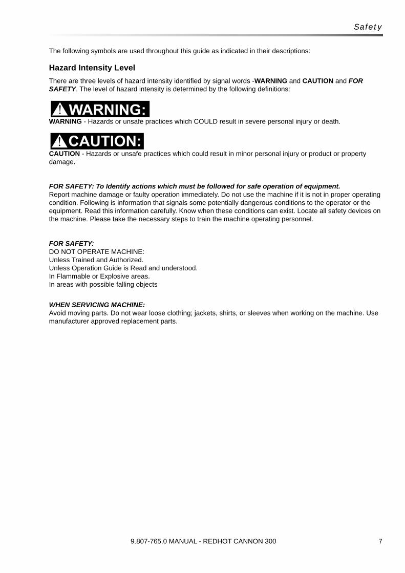
There are three levels of hazard intensity identified by signal words -WARNING and CAUTION and FOR SAFETY. The level of hazard intensity is determined by the following definitions:
WARNING - Hazards or unsafe practices which COULD result in severe personal injury or death.
CAUTION - Hazards or unsafe practices which could result in minor personal injury or product or property damage.
FOR SAFETY: To Identify actions which must be followed for safe operation of equipment.Report machine damage or faulty operation immediately. Do not use the machine if it is not in proper operating condition. Following is information that signals some potentially dangerous conditions to the operator or the equipment. Read this information carefully. Know when these conditions can exist. Locate all safety devices on the machine. Please take the necessary steps to train the machine operating personnel.
FOR SAFETY:DO NOT OPERATE MACHINE:Unless Trained and Authorized.Unless Operation Guide is Read and understood.In Flammable or Explosive areas.In areas with possible falling objects
WHEN SERVICING MACHINE:Avoid moving parts. Do not wear loose clothing; jackets, shirts, or sleeves when working on the machine. Use manufacturer approved replacement parts.
9.807-765.0 MANUAL - REDHOT CANNON 300

8
Safety
Les symboles suivants sont utilisés dans tout ce manuel, tels que décrits ici :
Niveau D'intensité Du Danger
Il existe trois niveaux d'intensité du danger, identifiés par des termes d'avertissement - AVERTISSEMENT, ATTENTION et POUR VOTRE SÉCURITÉ. Le niveau d'intensité du danger est déterminé par les définitions suivantes :
AVERTISSEMENT - Les dangers ou des pratiques contraires à la sécurité qui POURRAIENT entraîner des blessures personnelles ou la mort.
ATTENTION - Les dangers ou des pratiques contraires à la sécurité qui pourraient entraîner des blessures personnelles légères ou des dégâts sur le produit ou d'autres biens.
POUR DES RAISONS DE SÉCURITÉ : Pour identifier les actions qui doivent être exécutées pour un fonctionnement sûr de l'équipement.Signaler immédiatement tout dommage subi par la machine ou fonctionnement défectueux. Ne pas utiliser la machine si elle ne fonctionne pas correctement. Ci-dessous se trouvent les informations indiquant les condi-tions potentiellement dangereuses pour l'opérateur ou l'équipement. Lire attentivement ces informations. Être conscient que ces conditions peuvent survenir. Repérer tous les dispositifs de sécurité sur la machine. Suivre les étapes nécessaires de formation du personnel qui utilise la machine.
POUR DES RAISONS DE SÉCURITÉ :NE PAS FAIRE FONCTIONNER LA MACHINE :Sauf si le personnel est formé et autorisé.Sauf si le manuel d'utilisation est lu et compris.Dans des zones inflammables ou explosives.Dans des zones contenant des objets susceptibles de tomber
LORS DE L'ENTRETIEN DE LA MACHINE :Éviter les pièces mobiles. Ne pas porter de vêtements, vestes, chemises ou manches vagues lors de l'entretien de la machine. Utiliser les pièces de rechange approuvées par le fabricant.
9.807-765.0 MANUAL - REDHOT CANNON 300

9
Notes
9.807-765.0 MANUAL - REDHOT CANNON 300

10
Operations
Technical Specifications
ITEM DIMENSION/CAPACITY
Heat Input 293,982 BTU/h
Air Flow 2,531 CFM
Heat Output 258,704 BTU/h
Fuel Consumption 2.17 USgal/H
Power Supply Single Phase 120 V 60 Hz
Electrical Consumption 1,330 W 11.80 A
Nozzle 1.50-80° W USgal/H
Pump Pressure 174 psi
Static Pressure 0.5 in WC
Flue Diameter 5.9 in (149.9 mm)
Compulsory Flue Draft 0.05 in WC
Fuel Tank Capacity 27.7 Gal (104.9 L)
Adjustment of Combustion Air Flap
0.236 in (6 mm)
9.807-765.0 MANUAL - REDHOT CANNON 300

11
Operations
This appliance is not intended for use by persons (including children) with reduced physical, sensory or mental capabilities, or lack of experience and knowledge, unless they have been given supervision or instruction concerning use of the appliance by a person responsible for their safety. Children should be supervised to ensure that they do not play with the appliance.
Cet appareil n'est pas prévu à l'usage des personnes (enfants y compris) avec des possibilités physiques, sensorielles ou mentales réduites, ou le manque d'expérience et de connaissance, à moins qu'ils aient été donnés la surveillance ou l'instruction au sujet de l'utilisation de l'appareil par une personne chargée de leur sûreté. Des enfants devraient être dirigés pour s'assurer qu'ils ne jouent pas avec l'appareil.
ITEM MEASURE
Height 41.3in (1049 mm)
Length 68.5 in (1740 mm)
Width 27.6 in (701 mm)
Weight 275 lb (54.4 kg)
HEIGHT
WIDTHLENGTH
9.807-765.0 MANUAL - REDHOT CANNON 300

12
Operations
How this machine works
Before switching on the heater and, therefore, before plugging it into the electrical power supply, check that the power supply specifications are the same as those stated on the identification plate.
To operate the machine, must install the air dispersion cone (18) on the front of the machine as shown in the Operating Diagram.
Pour le fonctionnement, il est indispensable de monterle cône de diffusion d'air (18) sur la partie avant de lamachine, comme illustré par la figure ci-dessus (paragraphe “Schéma de fonctionne-ment”)
The power line must be earthed and fitted with a residual current circuit breaker. The heater plug must be inserted into a socket equipped with a mains switch.
La Ligne Électrique D’alimentation Du Générateur Doit Être Pourvue D’une Mise À La Terre Et D’un Disjoncteur Magnéto-thermique Avec Un Différentiel. La Fiche Électrique Du Générateur Doit Être Reliée À Une Prise Munie D’un Interrup-teur De Sectionnement.
The heater must be placed on a flat, stable, and leveled surface in order to prevent it from overturning and/or diesel leaks from the tank filler cap. You can run the generator in manual by setting switch (14) to ON.
The generator can only work automatically when a control device, such as for example a thermostat or a timer, is connected to the heater.
Connection to the heater is made by removing the socket cover (15) and inserting the thermostat plug.
To start the machine you must:
• If connected to the thermostat, turn the switch to (ON + )
• If not connected to the thermostat, turn the switch to (ON)
When unit is started for the first time or is started after the oil tank has been totally emptied, the diesel flow to the burner may be impaired by air in the circuit. In this case the control box will cut out the heater and it
might be necessary to renew the starting procedure once by depressing the reset button (13) for three seconds.
If the heater does not function, the first things to do are:
1. Check that the tank still contains some diesel.
2. Push reset button (13) for three seconds.
3. If the heater still does not function, see TROUBLESHOOTING” to identify the cause of the malfunction.
Never stop the machine by unplugging the electrical plug, this could cause overheating.
Ne jamais arrêter la machine en retirant la prise de courant : cette manoeuvre risque de provoquer une surchauffe.
Stopping The Heater
Set main switch (14) on “0” position or turn thermo-stat or other control device on lowest setting.
The flame goes out and the fan continues to work for approximately 90 sec. cooling the combustion chamber.
9.807-765.0 MANUAL - REDHOT CANNON 300

13
Operations
Components1. Combustion Chamber 10. Support/Handle
2. Burner 11. Wheel
3. Nozzle 12. Fuel Tank
4. Solenoid Valve 13. Reset Button of the Electronic Equipment
5. Diesel Pump 14. Main Switch
6. Motor 15. Room Thermostat Plug
7. Fan 16. Control Lamp
8. Fuel Filter 17. Power Cord
9. Fuel Circuit 18. Outlet Cone
19. Stack
9.807-765.0 MANUAL - REDHOT CANNON 300

14
Operations
Flame Control Cycles
Reset Lamp Light 2.1
During the operating condition, the reset button may have different type of light depending of its operating status
(FUNCTION LIGHT):
• flashing green: unit is in stand-by status, waiting for heating request.
• steady green light: unit is working normally (starting cycle or working cycle)
• flashing orange: presence of extraneous flame in stand-by status (waiting for heating request)
• flashing green / orange: presence of extraneous flame in prepurge time
• steady red light: the heater stops permanently in lock-out status and can restart only if reset button is pressed.To troubleshooting the unit when it is in lock-out condition, press the reset button for about 10 seconds and then release it. A diagnostic routine is enabled, causing the reset button on the main board to flash (SELF-DIAGNOSIS LIGHT) with the following descrip-tion
Operating Cycles 2.2
Depending on the type of the operating cycles, the main components (room thermostat, fan, ignition transformer, fuel valve) and controls element (photocell, reset button) are activated or de-activated according to specific rules and times.In the following diagrams are shown
• Starting cycle
• Shut off cycle
• Flame failure in starting cycle
• Extraneous light or flame during starting cycle
• Flame failure in running cycle.
Number of blinks Fault Description
2 Flame failure in starting cycle
4 Extraneous light / flame in starting cycle
7 Flame failure in running cycle
8 - 14 Internal failure of electronic control
9.807-765.0 MANUAL - REDHOT CANNON 300

15
Operations
The flame control unit starts the sequence of operation after a heating request (normal operation or thermostatoperation) and it consists of the following steps:
• Self-test (less than 3 s): self-check of electronics efficiency;
• Purging time TP (20 seconds): fan motor and ignition transformer are simultaneously switched on while the fuel valve remains closed to eliminate any fuel or unburnt residual.
During the purging stage, the flame signal is constantly monitored and any kind of failure leading to combustion prevents the burner ignition causing the controls to lock out the unit.In case of heating request opening (room thermostat opening), the control unit goes to stand-by position. The device remains in this status till closing of the room thermostat;
• Safety time (5 seconds): at the end of the purging time TP, the fuel valve is switched on and opens the fuel to the nozzle.
In case of flame detection failure by the end of the TS safety time, the control unit goes to lockout, and the fan motor, the ignition transformer and the fuel valve are de-energized, while the lockout signal is enabled.Otherwise, at the end of the TS safety time the control unit disables the ignition transformer and goes to running position.
• At the end of the TS safety time the control unit keeps the ignition transformer operating for about 30 s.
When the heating request (normal operation or thermostat operation) opens:• fuel valve and ignition transformer are switched off and the flame lights off;
• burner fan operates a 90 s post-purge ventilation
Restoring the heating request causes the post-purge to be interrupted and the starting cycle to be performed.
9.807-765.0 MANUAL - REDHOT CANNON 300
16
Operations
If during the safety time TS, the photocell monitors a flame failure (signal to photocell become lower than minimum) at the end of safety time the unit tries to restart twice: should the flame failure being confirmed, then the unit goes in lock out:
• burner fan, ignition transformer and fuel valve are de-energized;
• alarm lamp on reset button becomes steady red
If troubleshooting on reset button is activated as described in 2.1, then the alarm lamp on reset button starts flashing with 2 blinks.FUNCTION LIGHT: steady redSELF-DIAGNOSIS LIGHT: flashing red with 2 blinks
Unit can re-start only after pressing the reset button.NOTE: While starting cycle is repeated, a cooling time TXP is required to get the ignition transformer be ready to operate.
If during the pre-purge time the photocell monitors any residual flame then the unit goes in lock out:• burner fan stop to purging combustion chamber
• fuel valve and ignition transformer are de-energized
• reset lamp becomes steady red
If troubleshooting on reset button is activated as described in 2.1, then the alarm lamp on reset button startsflashing with 4 blinks.FUNCTION LIGHT: orange/green flashing then steady redSELF-DIAGNOSIS LIGHT: flashing red with 4 blinks
Unit can re-start only after pressing the reset button.
9.807-765.0 MANUAL - REDHOT CANNON 300

17
Operations
In case of flame failure in running status, the flame control unit make one trial restarting the unit.If the reason of flame failure is confirmed, then the unit stops in lock-out mode, and the reset lamp becomes steady red.If troubleshooting on reset button is activated as described in 2.1, then the alarm lamp on reset button startsflashing with 7 blinks.FUNCTION LIGHT: steady redSELF-DIAGNOSIS LIGHT: flashing red with 7 blinks
Unit can re-start only after pressing the reset button.
9.807-765.0 MANUAL - REDHOT CANNON 300

18
Operations
Safety Devices
The heater is fitted with an electronic device that controls the flame and the maximum safe tempera-ture by means of a photocell, an overheat thermostat and an air pressure switch.
The electronic device controls start/stop times and trips the safety in case of malfunctions. It has reset button (13) that can assume different colors (Function Light) depending on the function mode:
• Off: heater is in stand-by, waiting for heating call.
• Steady green: heater functioning normally.
• Steady red: heater in safety stop.
To restart heating after a safety stop, push reset button (13) for 3 seconds.
NEVER do more than two restarts in a row: Uncombusted diesel fuel may accumulate in the combustion chamber and suddenly flare up at the next restart.
Ne jamais effectuer plus de deux redémarrages consécutifs : le fuel imbrûlé peut s'accumuler dans la chambre de combustion et s'enflammer soudainement lors de la deuxième mise en marche.
If the safety stop persists, you have to find and eliminate the cause of the stop before you restart the heater.
Transport
Before moving the heater:
• Stop the heater as indicated in the “STOP” paragraph;
• Cut electrical power by removing the plug from the electrical socket.
• Wait until the heater cools.
Avant de déplacer l’appareil il faut :
• Arrêter le générateur en suivant les indica-tions du paragraphe “ARRET”.
• Débrancher l’alimentation électrique en enlevant la fiche de la prise de courant.
• Attendre que le générateur soit froid.
Before moving the heater, make sure the oil tank cap is securely attached.
Diesel may leak during handling and transport: the fuel tank cap is not sealed. This allows air to enter and allows the tank to be emptied while the heater is running.
En cours de déplacement et de transport du fuel peut s'échapper : en effet, le bouchon de remplis-sage du réservoir n'est pas étanche afin de permettre l'introduction d'air dans le réservoir et l'aspiration du fuel pendant le fonctionnement de la machine.
The heater can be supplied in a mobile version (with wheels) or wall version mounted on a support structure with anchors for fastening by means of ropes or chains. To move the mobile version, just grip the heater by the support handle and roll it on the wheels. The second version must be lifted by using a lift truck or similar equipment.
In this case, make sure that the ropes and/or chains are securely attached and that they are in perfect condition before you start to move the heater.
9.807-765.0 MANUAL - REDHOT CANNON 300

19
Maintenance
Maintenance
To ensure correct heater function, clean the combustion chamber, burner, and fan at regular intervals.
Before starting any maintenance procedure, ALWAYS:
• Stop the heater as indicated in the “STOP” paragraph;
• Cut electrical power by removing the plug from the electrical socket.
• Wait until the heater cools.
Avant de commencer une quelconque opération d’entretien il faut :
• Arrêter le générateur en suivant les indica-tions du paragraphe “ARRET”
• Débrancher l’alimentation électrique en enlevant la fiche de la prise de courant.
• Attendre que le générateur soit froid.
Every 50 hours of operation:
• Disassemble the filter cartridge, remove it, and clean it with clean diesel fuel;
• Disassemble the external cylindrical fairing and clean the inside and the fan blades;
• Check the condition of the leads and of the high-voltage connections to the electrodes;
• Disassemble the burner and clean all of its parts. Clean the electrodes and set the gap to the value specified here under the paragraph “REGULATION OF ELECTRODES”.
Maintenance Schedule
Periodic maintenance of the heater is necessary to ensure proper performance and to prevent failures and it shall be performed at the following periodic intervals:
Daily Maintenance• Inspect air inlet / air outlet and exhaust stack,
remove debris if any.
• If any air hose is installed, check that it is secure. Minimize bends and keeps ducts straight.
• Verify fuel tank is full.
• Verify that exhaust stack is properly installed.
Weekly Maintenance• Disassemble, inspect and clean fuel filter with
clean fuel.
• Remove top cover and clean the motor, fan blade and the interior shell.
• Inspect the fuel hose assembly and check for any leaks.
6 Months Maintenance• Disassemble burner head.
1. Inspect and clean burner diffuser.
2. Inspect and replace nozzle if necessary.
3. Clean ignition electrodes and adjust settings.
4. Check air combustion setting.
• Check overheat thermostat.
• Inspect and clean the combustion chamber.
• Open electric board, inspect electrical compo-nents and check connections.
• Check fuel pressure setting of fuel pump.
• Inspect and test the burner.
9.807-765.0 MANUAL - REDHOT CANNON 300

20
Maintenance
Troubleshooting
If the heater is still not working properly, please contact your nearest authorized dealer.
PROBLEM CAUSE SOLUTION
Motor Does Not Start, No Ignition
No electrical current.
Check mains cable.
Check proper positioning and func-tioning of switch.
Check fuse.
Wrong setting of room thermostat or other control.
Check correct setting of heater control. If thermostat, make sure selected temperature is higher than room temperature.
Thermostat or other control defective. Replace control device.
Electrical motor defective. Replace electrical motor.
Electrical motor bearings defective. Replace electrical motor bearings.
Burned out condenser. Replace condenser.
Motor Starts, No Ignition Or Cuts Out
Electric igniter defective.
Check connection of H.T. leads to electrodes and transformer.
Check electrodes setting (see scheme “REGULATION OF ELECTRODES”).
Check electrodes for cleanliness.
Replace H.T. Transformer.
Flame control box defective. Replace control box.
Photocell defective. Clean or replace photocell.
Not enough or no fuel at burner.
Check state of motor-pump plastic coupling.
Check fuel line system including fuel filter for possible leaks.
Clean or replace oil nozzle.
Solenoid defective.
Check electrical connection.
Check thermostat LI.
Clean or replace solenoid.
Motor Starts, Heater Emits Smoke
Not enough combustion air.
Make sure inlet and outlet are free.
Check setting of combustion air flap.
Clean burner disk.
Too much combustion air. Check setting of combustion air flap.
Fuel contaminated or contains water.Drain fuel in tank and replace with clean fuel.
Clean oil filter.
Air leaks in fuel circuit.Check the seals on the ducts and the diesel filter.
Not enough fuel circuit.Check pump pressure.
Clean or replace fuel nozzle.
Too much fuel at burner.Check pump pressure.
Replace nozzle.
Heater does not stop Solenoid defective.Replace solenoid coil or complete solenoid.
9.807-765.0 MANUAL - REDHOT CANNON 300

21
Maintenance
Wiring Diagram
AP Control Box MV Fan Motor
TA Room Thermostat Plug FUA Fuse 6.3 A
ST Electric Pilot Lamp RV Control Switch
LI1 Overheat Thermostat PA Air Pressure Switch
EV1 Solenoid Valve IO Stage FO Photocell
CO Capacitor RF Heated Filter
FU Fuse 20A IT Ignition Transformer
RE Relay
9.807-765.0 MANUAL - REDHOT CANNON 300

22
Maintenance
Chimney Layout Recommendation
The above recommendations are approximate. The chimney installation must comply with local regulation.
Description
A Minimum 3.2 feet (1m) 1 Anti-wind device provided with heater
B Minimum 3.2 feet (1m) 2 Horizontal crossing with 5° with upward slope
C As short as possible 3Chimney with minimum internal dimensions 7.9 in x 7.9 in (20 x 20 CM)
DGreater than or equal to diameter of heater smoke outlet
4 Chimney anti-explosion inspection door
E Minimum 3.2 feet (1m) 5 External buffer wall
6 Chimney draught H shape
9.807-765.0 MANUAL - REDHOT CANNON 300
23
Maintenance
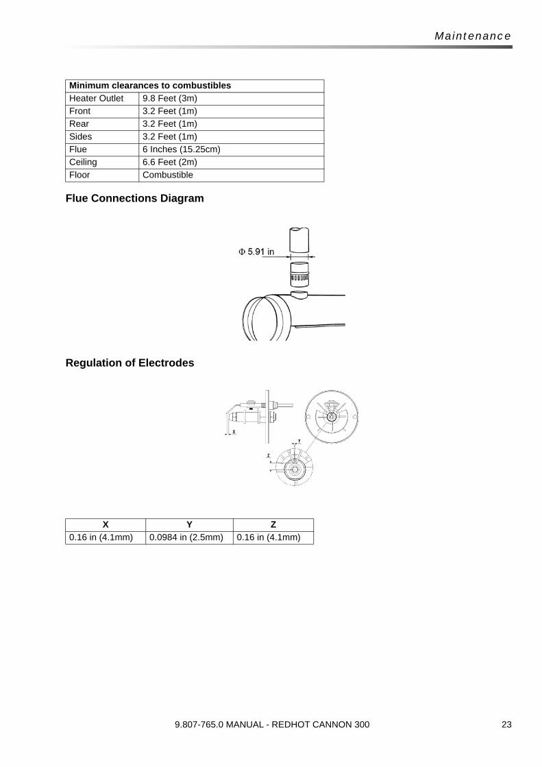
Flue Connections Diagram
Regulation of Electrodes
Minimum clearances to combustibles
Heater Outlet 9.8 Feet (3m)
Front 3.2 Feet (1m)
Rear 3.2 Feet (1m)
Sides 3.2 Feet (1m)
Flue 6 Inches (15.25cm)
Ceiling 6.6 Feet (2m)
Floor Combustible
X Y Z
0.16 in (4.1mm) 0.0984 in (2.5mm) 0.16 in (4.1mm)
9.807-765.0 MANUAL - REDHOT CANNON 300