operating instructions for miniclamps … pneumatic cylinder 23 mechanical kit 24 pneumatic kit 25...
TRANSCRIPT

031218
OPERATING INSTRUCTIONS FOR
MINICLAMPS FOR FASTENING CLAMPS

02Misati reserves the right to modify any characteristics of this catalogue.Check the last stage of information in www.misati.com
Operating Instructions for Fastening Clamps
INDEX
Which miniclamp should I use?
OPERATION PRINCIPLE 04
TYPES OF CLAMPS 05
BALL-ENDED SCREW 06
SHIM KIT 07
JAW BLOCK 08
Use
HOW TO ADJUST THE FORCE OF A MINICLAMP 10-13
NON-REVERSIBLE MINIPINCER 14
FORCE / “α” ANGLE 15
FORCE / LENGTH OF THE ARM 16
WEIGHT / ARM RADIUS RELATIONSHIP 17
RETENTION FORCE 18
MAXIMUM LATERAL FORCE 19
GUARANTEE 20
Maintenance
MAINTENANCE: FORCE MECHANISM 22
MAINTENANCE: PNEUMATIC CYLINDER 23
MECHANICAL KIT 24
PNEUMATIC KIT 25
CHANGE OF THE ARM 26-27

03
© System patented by MISATI, S.L.
Av. de la Riera 15, E-08960 Sant Just Desvern, Barcelona, Spain
Tel. +34 93 440 47 27 - [email protected] - www.misati.com
Range:
Which Miniclamp Should I Use?
OPERATION PRINCIPLE 04
TYPES OF CLAMPS 05
BALL-ENDED SCREW 06
SHIM KIT 07
JAW BLOCK 08

04Misati reserves the right to modify any characteristics of this catalogue.Check the last stage of information in www.misati.com
¿Range: Which Miniclamp Should I Use?
OPERATION PRINCIPLE
CLOSING MINICLAMP
The miniclamp has a double eff ect pneumatic cylin-der which transmits a turning movement to the clamping arm along the shaft. Thanks to the special shape of the oblong hole, the miniclamp makes a big force.
OPENING MINICLAMP
1 2 3
4 5 6

05Misati reserves the right to modify any characteristics of this catalogue.Check the last stage of information in www.misati.com
¿Range: Which Miniclamp Should I Use?
TYPES OF CLAMPS
The clamping component can be parallel (BL type) or perpendicular (BI, BC types)
with regard to the body. The clamp can be applied on any spatial position.

06Misati reserves the right to modify any characteristics of this catalogue.Check the last stage of information in www.misati.com
¿Range: Which Miniclamp Should I Use?
BALL-ENDED SCREW
RIBBED SURFACE:
RG-... RGI-...
FLAT SURFACE:
RP-... RGD-...
RP-... RGD-... RG-...
B
D
C
ØA
5º CºCº
A
B
Examples of applications
RGI-...
B
AE
D Cº
Cº
RP-... RGD-... RG-... RGI-... RN-...
Weight (kg)
RP-08/D 0,030-0,034
RP-10/D 0,063-0,072
RGD-20 0,011
RGD-32 0,021
RG-20 0,012
RG-32 0,022
RG-20-30 0,01
RG-32-40 0,02
RGI-20 0,01
RGI-30 0,02
RN-08/D 0,030-0,034
RN-...
D
C
ØA
B
RP-...
RG-...RGD-... RGI-...
RG
TYPE A B C
RG-20 M8 40 9
RG-32 M10 50 9
RG-20-30 M8 30 9
RG-32-40 M10 40 9
RP
TYPE A B C D
RP-08/D 16 M8 9 48 63
RP-10/D 20 M10 11 54 64 84
RGD
TYPE A B C
RGD-20 M8 41,6 0
RGD-32 M10 51,9 0
RGI
TYPE A B C D E
RGI-01 13 M8 9 21 8
RGI-02 12 M3 9 11
RN
TYPE A B C D
RN-08/D 16 M8 18 63
Bolts included
Material: hardened steel & Delrin (RGD-...) Material: hardened steel (RP-..., RG-..., RGI-..., RN-...) Material: neoprene (RN-...)
For very delicate pieces, it is recommended
to use the Flat Ball-Ended Screw RP-... or RGD-...

07Misati reserves the right to modify any characteristics of this catalogue.Check the last stage of information in www.misati.com
Examples of applications
¿Range: Which Miniclamp Should I Use?
SHIM KIT
TYPE A B C D THICKNESS
GBK-20 30 17 13 9.2 0.1 0.2 0.3 0.5 1
GBK-20 40 23 17 11.2 0.1 0.2 0.3 0.5 1
GBK-40 50 30 20 13.2 0.1 0.2 0.3 0.5 1
GBK-20 GBK-32
Adjustment of 0 to 2mm can be made on jaw blocks SC-... with the shims in this kit (GBK-...).
GBK-40
Thic
knes
s

08Misati reserves the right to modify any characteristics of this catalogue.Check the last stage of information in www.misati.com
Examples of applications
¿Range: Which Miniclamp Should I Use?
JAW BLOCK
Material: steel Recommended treatment:
quenching & tempering
Area to be machined by the customer according to the surface
to fasten.
TYPE A B C D ØE F G
SC-A-20 25 13 30 17 9 M6 13
SC-A-32 35 17 40 23 11 M8 17
SC-A-40 45 20 50 30 13 M10 20
SC-A-50 50 20 60 40 13 M10 20
SC-AL-20 50 13 30 17 9 M6 13
SC-AL-32 70 17 40 23 11 M8 17
SC-AL-40 80 20 50 30 13 M10 20
SC-AL-50 85 20 60 40 13 M10 20

09
© System patented by MISATI, S.L.
Av. de la Riera 15, E-08960 Sant Just Desvern, Barcelona, Spain
Tel. +34 93 440 47 27 - [email protected] - www.misati.com
Use
HOW TO ADJUST THE FORCE OF A MINICLAMP 10-13
NON-REVERSIBLE MINIPINCER 14
FORCE / “α” ANGLE 15
FORCE / LENGTH OF THE ARM 16
WEIGHT / ARM RADIUS RELATIONSHIP 17
RETENTION FORCE 18
MAXIMUM LATERAL FORCE 19
GUARANTEE 20

10Misati reserves the right to modify any characteristics of this catalogue.Check the last stage of information in www.misati.com
Use
HOW TO ADJUST THE FORCE OF A MINICLAMP
• With the mobile arm open, you have to loosen the nuts that
hold the ribbed ball-ended screws (orange colour).
• Turn the screws up until there is enough space to
place a sheet between them and the lower gripper
fi nger or the static arm of the miniclamp.
• Close the minipincer until it reaches the fi nal position. In
this position, the minipincer is non-reversible, i.e., it will
not open unless any compressed air is injected in it.
To close the miniclamp, you’ll need
to inject some compressed air into
the hole with a “+” mark on.
4 Adjust the force
1 Open the pincer and place the sheet
2 Close the pincer
3 Bring screws down
• We will begin by deciding the force we’d like to obtain. This
force should be enough to fasten the sheet correctly during
the transfer process.
• Next, we will look for this value in the tables enclosed, taking
the type of miniclamps that we are using and the minimum
working pressure into
BCP-... / BC-... / BL-... MINICLAMP
For example:
If we usually work at a pressure of 6 bar that
sometimes falls to 5 bar, then we will look
for a force to work at 5 bar.
• With the arm closed, bring both screws over to
the sheet until they contact it without pressure.
• In case of using Jaw Blocks (SC or SCL), we will
need to use diff erent thickness shims (GBK-…)
until the jaw block contacts the sheet.

11Misati reserves the right to modify any characteristics of this catalogue.Check the last stage of information in www.misati.com
Use
HOW TO ADJUST THE FORCE OF A MINICLAMP
H(mm)
H(mm)
α• Take the sheet out carefully so that you don’t turn the
screws. Then, with an Allen key, turn the screws cloc-
kwise the value from the table, assembling high security
washers at a 35 Nm torque. The turn can be measured in
degrees (α) or in height (H), i.e. the number of millimeters
that the screw is moving, as you think best.
Example:
To obtain 102 daN force with a BL-20-30 pincer that
works at a minimum pressure of 5 bar, we should turn the
screws 170º, or until they go down 0.60 mm.
270º 90º
180º 170º
0º
α
MINICLAMP BCP, BC MINICLAMP BL
MINICLAMP Ø20 MINICLAMP Ø32
TURN SCREW
(α)H
(mm)FORCE (daN)
TURN SCREW
(α)H
(mm)FORCE (daN)
4 BAR
156º 0,54 60 240º 0,90 100
180º 0,63 69 300º 1,10 136
5 BAR
196º 0,68 75 300º 1,25 135
225º 0,78 86 360º 1,5 170
6 BAR
235º 0,81 90 360º 1,50 170
270º 0,93 103 420º 1,75 205
MINICLAMP Ø20 MINICLAMP Ø32
TURN SCREW
(α)H
(mm)FORCE (daN)
TURN SCREW
(α)H
(mm)FORCE (daN)
4 BAR
128º 0,40 81 197º 0,82 146
149º 0,52 108 247º 1,03 195
5 BAR
170º 0,60 102 222º 0,92 182
192º 0,67 135 271º 1,13 243
6 BAR
192º 0,67 122 247º 1,02 219
213º 0,74 162 296º 1,24 292
MINICLAMP Ø40 MINICLAMP Ø50
TURN SCREW
(α)H
(mm)FORCE (daN)
TURN SCREW
(α)H
(mm)FORCE (daN)
4 BAR
224º 1,08 258 262º 1,27 325
274º 1,33 330 309º 1,50 433
5 BAR
224º 1,08 323 293º 1,42 407
299º 1,45 413 355º 1,72 543
6 BAR
274º 1,33 388 324º 1,57 488
324º 1,57 496 401º 1,95 651
Maximum Force
Recommended Force

12Misati reserves the right to modify any characteristics of this catalogue.Check the last stage of information in www.misati.com
HOW TO ADJUST THE FORCE OF A MINICLAMP
MINICLAMP BL...SC / SCL, BI ...SC / SCL
• With the arm closed, bring both screws over to the
sheet until they contact it without pressure.
• In case of using Jaw Blocks (SC or SCL), we will need
to use diff erent thickness shims (GBK-…) until the jaw
block contacts the sheet.
4 Adjust the force
1 Open the pincer and place the sheet
2 Close the pincer
3 Bring screws down
• With the mobile arm open, you have to loosen the nuts that
hold the ribbed ball-ended screws (orange colour).
• Turn the screws up until there is enough space to
place a sheet between them and the lower gripper
fi nger or the static arm of the miniclamp.
• Close the minipincer until it reaches the fi nal posi-
tion. In this position, the minipincer is non-reversi-
ble, i.e., it will not open unless any compressed air
is injected in it.
To close the miniclamp, you’ll need
to inject some compressed air into
the hole with a “+” mark on.
For example:
If we usually work at a pressure of 6
bar that sometimes falls to 5 bar, then
we will look for a force to work at 5 bar.
Use
• We will begin by deciding the force we’d like to obtain.
This force should be enough to fasten the sheet correctly
during the transfer process.
• Next, we will look for this value in the tables enclosed,
taking the type of miniclamps that we are using and the
minimum working pressure into

13Misati reserves the right to modify any characteristics of this catalogue.Check the last stage of information in www.misati.com
Use
Esfuerzo máximoEsfuerzo aconsejableEsfuerzo mínimo
270º 90º
180º222º
0º
HOW TO ADJUST THE FORCE OF A MINICLAMP
Ø20 Ø32
TURN SCREW(mm)
FORCE (daN)
TURN SCREW(mm)
FORCE (daN)
4 BAR
0,3 54 0,7 97
0,4 81 0,8 146
0,5 108 1,0 195
5 BAR
0,4 67 0,8 122
0,6 102 0,9 182
0,7 135 1,1 243
6 BAR
0,5 81 0,9 146
0,7 122 1,0 219
0,8 162 1,2 292
Ø20 Ø32 Ø40 Ø50
TURN SCREW(mm)
FORCE (daN)
TURN SCREW(mm)
FORCE (daN)
TURN SCREW(mm)
FORCE (daN)
TURN SCREW(mm)
FUERZA (daN)
4 BAR
0,3 54 0,7 97 1,0 187 1,1 217
0,4 81 0,8 146 1,1 258 1,3 325
0,5 108 1,0 195 1,3 330 1,5 434
5 BAR
0,4 67 0,8 122 1,0 234 1,1 271
0,6 102 0,9 182 1,1 323 1,4 407
0,7 135 1,1 243 1,5 413 1,7 542
6 BAR
0,5 81 0,9 146 1,1 281 1,3 325
0,7 122 1,0 219 1,3 388 1,6 488
0,8 162 1,2 292 1,6 496 2,0 651
MINICLAMP BI...SC Y SCL MINICLAMP BL...SC Y SCL
Ejemplo:
Para obtener un esfuerzo de 102 daN con una mibrida
BL-20-30 que trabaja a un mínimo de 5 bar de presión,
deberíamos girar los pisadores 170º o hasta que hubieran
bajado 0,60 mm.
αα
par=35 Nm
par=35 Nm
• Take the sheet out carefully so that you
don’t turn the screws. Then, with an
Allen key, turn the screws clockwise the
value from the table, assembling high
security washers at a 35 Nm torque.
The turn can be measured in degrees
(α) or in height (H), i.e. the number of
millimeters that the screw is moving,
as you think best.
14Misati reserves the right to modify any characteristics of this catalogue.Check the last stage of information in www.misati.com
Use
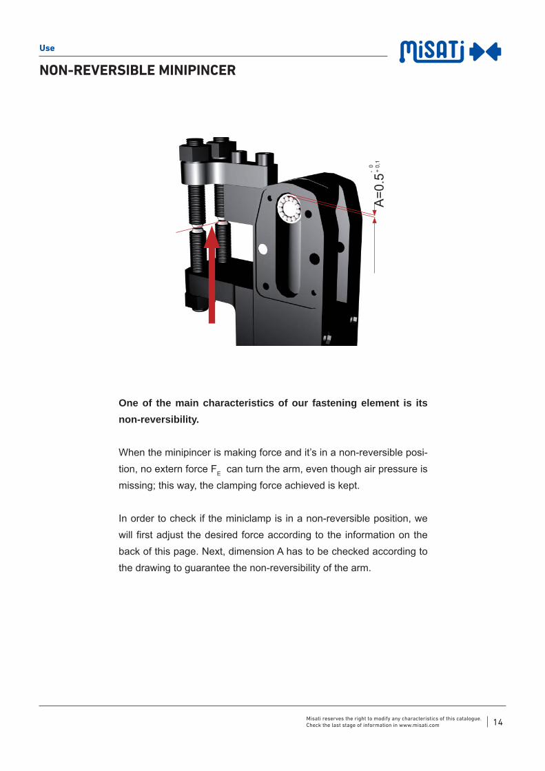
NON-REVERSIBLE MINIPINCER
One of the main characteristics of our fastening element is its non-reversibility.
When the minipincer is making force and it’s in a non-reversible posi-tion, no extern force FE can turn the arm, even though air pressure is missing; this way, the clamping force achieved is kept.
In order to check if the miniclamp is in a non-reversible position, we will fi rst adjust the desired force according to the information on the back of this page. Next, dimension A has to be checked according to the drawing to guarantee the non-reversibility of the arm.
A=0
.5 -
0 +
0,1

15Misati reserves the right to modify any characteristics of this catalogue.Check the last stage of information in www.misati.com
Use
FORCE / ““ ANGLE
Depending on the angle of the arm at the clamping position, the force changes.
BL-...
BI-...
BL, BI-20 BL, BI-32 BL, BI-40 BL, BI-50

16Misati reserves the right to modify any characteristics of this catalogue.Check the last stage of information in www.misati.com
Use
FORCE / LENGTH OF THE ARM
The clamping force is determined by the distance between the turning centre and the point of contact. The length and mass of the arm should be as small as possible. Apart from standard couplings, pneumatic cushioning will be necessary.
DISTANCE TO
THE TURNING
SHAFT
FORCE (daN)
BL-20 BL-32 BL-40 BL-50
30 200 500 1000 1583
40 150 375 750 1187
50 120 300 600 950
60 100 250 500 792
70 85 214 428 678
80 75 187 375 595
DISTANCE TO
THE TURNING
SHAFT
FORCE (daN)
BI-20 BI-32 BI-40 BI-50
40 150 375 750 1187
50 120 300 600 950
60 100 250 500 792
70 85 214 428 678
80 75 187 375 594
DISTANCE TO
THE TURNING
SHAFT
FORCE (daN)
BC-20 BC-32 BC-40
50 60 150 300
60 50 125 250
70 42 107 214
80 37 93 187
=0º P=6bar
=0º P=6bar
=0º P=6bar

17Misati reserves the right to modify any characteristics of this catalogue.Check the last stage of information in www.misati.com
Use
WEIGHT / ARM RADIUS RELATIONSHIP
In order to limit the impact of the arm due to kinetic energy, the application of special couplings with an excess length or mass requires a system of pneumatic cushioning and fl ow regulators. We would advise to respect the weight/ length relationships, according to the following graphs:
TYPEMaximum
Load Torque
Cushioned
Load Torque
BL, BI-20 1Nm 0.15 Nm
BL,BI-32 1.25 Nm 0.33 Nm
BL,BI-40 1.5 Nm 0.5 Nm
BL, BI-50 2.5 Nm 1Nm
TYPE BL, BI-20 TYPE BL, BI-32
TYPE BL, BI-40
TYPE BL, BI-50
Centre of mass
BL
BI
Weight
We
igh
t (K
g)
We
igh
t (K
g)
We
igh
t (K
g)
We
igh
t (K
g)
Weight
Weight

18Misati reserves the right to modify any characteristics of this catalogue.Check the last stage of information in www.misati.com
RETENTION FORCE
Use
Loads and momentums appearing in these tables are in constant service. Values are higher with specifi c loads.
TYPE FL (daN) ML (Nm) L
BL-20 703 190 27
BL32 1287.6 470 36.5
BL-40 1694.3 753.9 44.5
BL-50 2266.6 1189.9 52.5
TYPE FI (daN) ML (Nm) I
BI-20 400 190 47.5
BI-32 696.2 470 67.5
BI-40 913.9 753.9 82.5
BI-50 1233.1 1189.9 96.5

19Misati reserves the right to modify any characteristics of this catalogue.Check the last stage of information in www.misati.com
MAXIMUM LATERAL FORCE
Use
Loads and torques appearing in these tables are in constant service. Values are higher with specifi c loads.
TYPE FL (daN) ML (Nm)
BL / BI-20 440 220
BL / BI-32 1184 592
BL / BI-40 2007 1003
BL / BI-50 3318 1659

20Misati reserves the right to modify any characteristics of this catalogue.Check the last stage of information in www.misati.com
GUARANTEE
Use
001-01-15
Month YearNumberof minipincer
LIFEMINICLAMP, which are identifi ed in this certifi cate, are guarante-
ed by MISATI, S.L. for 7 YEARS against any manufacturing defect
aff ecting their correct operation, as from the date of guarantee
(indicated with number of minipincer, month and year on the ac-
tual minipincer).
SCOPEThe guarantee covers all faulty parts and labour required for their
repair in our workshops during the guarantee period.
GUARANTEE DOES NOT INCLUDE:• Any possible damages occasioned by mishandling, inappro-
priate use, negligence, overloading or abandonment of the
miniclamp, pressure increases, faulty installations and other
external causes.
• Any repairs or adjustments carried out by people not con-
nected with or expressly authorized by MISATI, S.L.
• Any parts prone to wear and tear.
• Damages caused by any machine downtime.

21
© System patented by MISATI, S.L.
Av. de la Riera 15, E-08960 Sant Just Desvern, Barcelona, Spain
Tel. +34 93 440 47 27 - [email protected] - www.misati.com
Maintenance
MAINTENANCE: FORCE MECHANISM 22
MAINTENANCE: PNEUMATIC CYLINDER 23
MECHANICAL KIT 24
PNEUMATIC KIT 25
CHANGE OF THE ARM 26-27

22Misati reserves the right to modify any characteristics of this catalogue.Check the last stage of information in www.misati.com
MAINTENANCE: FORCE MECHANISM
Maintenance
To guarantee a long life for our minipincers, it is essential to make a preventive maintenance, depending on the aggressiveness of the environment.
1 DISMANTLING
Dismantle both lateral covers.
2 CLEANING BLOWING
In order to free any foreign particle, project compres-
sed air in all directions on the hole and in diff erent
positions of the arm.
3 LUBRICATION
Spray on the hole with a lubricant for bearings in
diff erent positions of the arm.
4 ASSEMBLY
Put both covers on the clamp.
1
2
3
4
GAS OIL
23Misati reserves the right to modify any characteristics of this catalogue.Check the last stage of information in www.misati.com
Maintenance
MAINTENANCE: PNEUMATIC CYLINDER
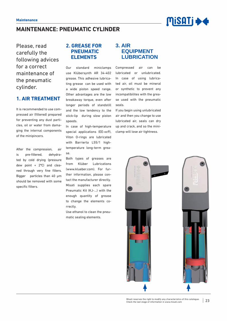
Please, read carefully the following advices for a correct maintenance of the pneumatic cylinder.
1. AIR TREATMENT
It is recommended to use com-
pressed air (fi ltered) prepared
for preventing any dust parti-
cles, oil or water from dama-
ging the internal components
of the minipincers.
After the compression, air
is pre-fi ltered, dehydra-
ted by cold drying (pressure
dew point + 2ºC) and clea-
ned through very fi ne fi lters.
Bigger particles than 40 μm
should be removed with some
specifi c fi lters.
2. GREASE FOR PNEUMATIC ELEMENTS
Our standard miniclamps
use Klübersynth AR 34-402
grease. This adhesive lubrica-
ting grease can be used with
a wide piston speed range.
Other advantages are the low
breakaway torque, even after
longer periods of standstill
and the low tendency to the
stick-lip during slow piston
speeds.
In case of high-temperature
special applications (EE-xx9),
Viton O-rings are lubricated
with Barrierta L55/1 high-
temperature long-term grea-
se.
Both types of greases are
from Klüber Lubrications
(www.klueber.com). For fur-
ther information, please con-
tact the manufacturer directly.
Misati supplies each spare
Pneumatic Kit (KJ-...) with the
enough quantity of grease
to change the elements co-
rrectly.
Use ethanol to clean the pneu-
matic sealing elements.
3. AIR EQUIPMENT LUBRICATION
Compressed air can be
lubricated or unlubricated.
In case of using lubrica-
ted air, oil must be mineral
or synthetic to prevent any
incompatibilites with the grea-
se used with the pneumatic
seals.
If you begin using unlubricated
air and then you change to use
lubricated air, seals can dry
up and crack, and so the mini-
clamp will lose air tightness.

24Misati reserves the right to modify any characteristics of this catalogue.Check the last stage of information in www.misati.com
Maintenance
MECHANICAL KIT FOR
DEL TIPO BL, BI, BC MINICLAMPS
Dismantling the Mechanical Kit
Assembling the Mechanical Kit
1Dismantle both lateral covers
Allen keys 2,5 y 3
6Assemble the in-ternal bushing of the arm with the help of the bolt.
7Lay the clamp down horizontally and place the shaft and bea-rings in it
8Put the Bakelite cover & sensor, or lateral cover,on the clamp
Allen keys
9Turn the clamp and place the bearing in
10Turn the clamp and place the bearing in
Allen keys 2,5
2Take bearings & bolt out
3Push the shaft down to the end
4Take the internal bushing out of the arm
5Push the shaft up to the halfway of the oblong hole of the body
The Mechanical Kit of GC miniclamps must be changed in MISATI workshops.

25Misati reserves the right to modify any characteristics of this catalogue.Check the last stage of information in www.misati.com
Maintenance
11Place the piston & the cylinder bush according to the drawing
16Assemble the internal bushing of the arm with the help of the bolt
17Lay the clamp down horizon-tally and place the shaft and bearings in it
18Put the Bakelite cover & sensor, or lateral cover, on the clamp
Allen key 3
19Turn the clamp and place the bearing in
20Put the lateral cover on the clamp
Allen key 2,5
12Place the piston & the cylinder bush according to the drawing
13Approach the shaft to the arm and tighten the screw
Allen key
14Screw the head in with the help of two Allen screws
Spanner
15Push the shaft up to the halfway of the oblong hole of the body
PNEUMATIC KIT FOR
DEL TIPO BL, BI, BC MINICLAMPS

26Misati reserves the right to modify any characteristics of this catalogue.Check the last stage of information in www.misati.com
Maintenance
CHANGE OF THE ARM BL,BI
Dismantling the arm Assembling the arm
1Dismantle both lateral covers
Allen keys 2,5 & 3
8Assemble the bolt
Centre punch & hammer
9Put the shaft up to the halfway of the oblong hole of the body
11Lay the clamp down horizon-tally and place the shaft and bearings in it
13Turn the clamp and place the bearing in
14Put the lateral cover on the clamp
Allen key 2,5
12Put the Bakelite cover & sensor, or lateral cover, on the clampAllen key 3
10Assemble the in-ternal bushing of the arm with the help of the bolt
2Take bearings & bolt out
3Push the shaft down to the end
4Take the internal bushing out of the arm
5Take the bolt out
Centre punch & hammer
6Take the arm out
7Assemble the arm

27Misati reserves the right to modify any characteristics of this catalogue.Check the last stage of information in www.misati.com
Maintenance
CHANGE OF THE ARM BC
Dismantling the arm Assembling the arm
1Dismantle both lateral covers
Allen keys 2,5 & 3
8Assemble the bolt
Centre punch & hammer
9Put the shaft up to the halfway of the oblong hole of the body
11Lay the clamp down horizon-tally and place the shaft and bearings in it
13Turn the clamp and place the bearing in
14Put the lateral cover on the clamp
Allen key 2,5
12Put the Bakelite cover & sensor, or lateral cover, on the clampAllen key 3
10Assemble the in-ternal bushing of the arm with the help of the bolt
2Take bearings & bolt out
3Push the shaft down to the end
4Take the internal bushing out of the arm
5Take the bolt out
Centre punch & hammer
6Take the arm out
7Assemble the arm

MISATI, S.L.
Av. de la Riera 15 E-08960 Sant Just Desvern
Barcelona, SpainTel. +34 93 440 47 [email protected]
www.misati.com