operating instructions for wp12 marine diesel...
TRANSCRIPT
PART NO: 100000154
OPERATING INSTRUCTIONS FORWP12 MARINE DIESEL ENGINE

FOREWORD
This manual contains installation and operating information of WP12 series Weichai marine diesel engine. Content of this manual is intended to explain about safety, installation guidelines, operation and maintenance instructions, specifications for fuel, lube oil & coolant. Information provided in this manual is limited to regular operations and maintenance. Hence cannot be considered for major overhaul or repair.
The technician who is operating any Weichai marine diesel engine must understand the safe operating procedure, routine inspection and maintenance practices. Repairing of the engine must be carried out by trained professional and this service is available in all our authorized service centers.
As a policy of continuous improvement, Weichai Power Company Ltd reserves the right to change /modify/ upgrade the content of this manual at any time without prior notice.
WP12 series marine diesel engine is the upgraded version of TD226B series. It has distinguishing features like improved reliability, improved emission qualities, quick starting, improved maintenance interval and low operating cost. Weichai engines are popular for the best in class fuel economy, low noise & vibrations and comparatively low engine room temperature. WP12 series marine diesel engines are the ideal propulsion power for small & medium type fishing boats, for inland water transportation vessels and high-speed ships.

CONTENTS
SECTION - ISafety Regulations ....................................................................1 1.1 General Instructions .........................................................1 1.2 Correct use .......................................................................1 1.3 Modifications or conversions ............................................1 1.4 Spare parts .......................................................................1 1.5 Reworking of components ................................................1 1.6 Safety regulations for startup and operation ....................2
SECTION - IITechnical Specification .............................................................3 2.1 Main Specification ...........................................................3 2.2 Specification for Sub-Assemblies and Accessories .........4 2.3 Overall Dimensions Of WP12 Marine Diesel Engine ......5 2.4 Engine Model Identification ..............................................6 2.5 Engine Model and Power Range .....................................6
SECTION – IIIInstallation Guidelines For Engines And Accessories ..........7 3.1 De-preservation of new engine ........................................7 3.2 Engine installation procedure ...........................................7 3.3 Installation of air inlet system ...........................................8 3.4 Installation of exhaust system ..........................................8 3.5 Installation of cooling system ...........................................9 3.5.1 Fresh water cooling system ....................................9 3.5.2 Sea water system ...................................................9 3.6 Installation of diesel engine front end output ....................9 3.7 Installation of electrical and engine control system ..........10

SECTION – IVOperating Instructions ..............................................................12 4.1 Safety precautions for operation of diesel engine ............12 4.2 General instructions .........................................................12 4.3 Preparation for first start ...................................................12 4.3.1 Cooling system .......................................................13 4.3.2 Lubrication system .................................................14 4.3.3 Checking the oil level .............................................15 4.3.4 After an extended storage ......................................15 4.3.5 Fuel system ............................................................16 4.3.5.(a) Priming the fuel system .....................................17 4.3.6 Electrical system ...................................................17 4.3.7 Engine starting, operating and stopping .................17 4.3.7.(a) Normal starting ..................................................18 4.3.8 Running in period ...................................................19 4.4 Regular operation .............................................................20 4.4.1 Engine starting .......................................................21 4.4.2 Engine warm up .....................................................21 4.4.3 Monitoring the engine oil ........................................21 4.4.4 Monitoring the engine coolant ................................22 4.4.5 Monitoring the exhaust gas ....................................23 4.4.6 Engine shutdown ....................................................23
SECTION - VPeriodic Maintenance ...............................................................27 5.1 Safety precautions ...........................................................27 5.2 Importance of periodic maintenance ................................27 5.3 Replacement of parts and components ...........................27 5.4 Reliability of parts .............................................................28 5.5 Safe use of oil and fuel in a diesel engine ........................28

5.6 Disposal of used oil or fuel ...............................................28 5.7 Periodic Maintenance instructions ...................................29 5.7.1 Check air filter ........................................................29 5.7.2 Cleaning air filter ....................................................30 5.7.3 Replacement of engine oil ......................................30 5.7.4 Replacement of oil filter ..........................................31 5.7.5 Cleaning of oil gas separator ..................................32 5.7.6 Replacement of fuel filter ........................................32 5.7.7 Air bleeding from fuel system .................................33 5.7.8 Adjustments and replacement of V-Belt .................33 5.7.9 Arrangement of cylinder head and valve ................34 5.7.10 Adjustment of valve clearance ..............................34 5.8 Maintenance recommendation .........................................36
SECTION - VISpecifications for Lubricant, Coolant and Fuel ......................44 6.1 Lubricant ..........................................................................44 6.1.1 The functioning of lubricating oil in a diesel engine 44 6.1.2 Engine oil consist of ...............................................44 6.1.3 Why oil to be drained? ............................................44 6.1.4 How engine oil performance getting deteriorated ...44 6.1.5 Oil performance classification system ....................45 6.1.6 SAE viscosity recommendations ............................45 6.2 Engine oil recommendations for Weichai engines ...........46 6.3 Grease Recommendations ..............................................47 6.4 Fuel oil recommendations ................................................47 6.5 Coolant .............................................................................50 6.6 A good coolant should have following properties .............50

1
SECTION - ISAFETY REGULATIONS
1.1 General InstructionsWP12 series Weichai marine diesel engine has been designed and assembled by the company, meeting all applicable safety regulations of international standards. In addition to the instructions in this manual, applicable industrial safety regulations regarding accident prevention and environmental protection must be followed by the operator of this engine.
The engine may nevertheless present a risk of injury or damage in the following cases:• Incorrect use• Unauthorized modifications or conversions• Non-compliance with the safety instructions• Skipping of routine checks and inspection• Operation, maintenance and repair by unqualified personnel
1.2 Correct useEvery engine is designed and built to suit a desired application. WP12 Weichai- Marine diesel engine is specifically designed for the use of marine propulsion. Any other use is being considered as improper use. The engine manufacturer accepts no-liability whatsoever for resultant damage or injury. In such cases, the responsibility will be borne by the user only.Correct use also includes periodically monitoring engine operating parameters, carryout routine inspection and maintenance as per recommendation by the company.
1.3 Modifications or conversionsAny modification on engine may impair its performance and shorten its life. Unauthorized modifications on the engine are also a risk to human and machine safety. The company will accept no liability or warranty claims for any damage caused by unauthorized modifications or conversions.
1.4 Spare partsOnly Weichai genuine spare parts must be used to replace components or assemblies. The company accepts no liability whatsoever for damage or injury resulting from the use of other spare parts and the warranty shall be void in such case.
1.5 Reworking of componentsAny repair or overhaul of the engine must be carried out by the company authorized service center. The company accepts no liability whatsoever for damage or injury resulting from the repair by un-authorized person.

1.6 Safety regulations for startup and operation1.6.1 Before installing or operating the engine, the operator should carefully read and understand the content of this manual to get familiar with the engine structure, correct operation and maintenance procedures.1.6.2 This diesel engine is a high speed rotating machinery. When the engine is in operation, do not touch any moving parts.1.6.3 Tampering with the fuel injection and electronic system could affect engine power output and threat to engine safety. Any attempt, to tamper with will void the warranty and the company will not be responsible for any injury due to alteration.1.6.4 If the engine is new or overhauled in major parts (in either case), follow the 60 hours of running in procedure.1.6.5 Select the lubricating oil, coolant and fuel as recommended in section-VI.1.6.6 Always use recommended lubricant and coolant. The company recommends to use premixed coolant for better protection of engine cooling system. Never use sea water or riverwater in engine internal cooling system.1.6.7 Gradually speed up the engine after starting from the cold state. Do not raise the speed suddenly or let the engine run with no load for a long time.1.6.8 Never operate the engine without air filters. Inducting un-filtered air to the combustion system will shorten engine life and adversely affect the engine performance.1.6.9 Any service or repair related to the electrical system must be carried out by a trained electrical/electronic professional.1.6.10 Prevention of harms caused by engine emission: It is absolutely prohibited to operate the engine in a closed room without proper ventilation, because exhaust gas from engine emission is toxic, which is harmful to the human health.
3
SECTION - IITECHNICAL SPECIFICATION
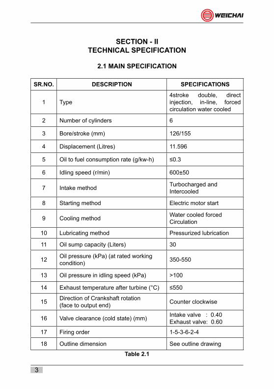
2.1 MAIN SPECIFICATION
SR.NO. DESCRIPTION SPECIFICATIONS
1 Type4stroke double, direct injection, in-line, forced circulation water cooled
2 Number of cylinders 6
3 Bore/stroke (mm) 126/155
4 Displacement (Litres) 11.596
5 Oil to fuel consumption rate (g/kw-h) ≤0.3
6 Idling speed (r/min) 600±50
7 Intake method Turbocharged andIntercooled
8 Starting method Electric motor start
9 Cooling method Water cooled forcedCirculation
10 Lubricating method Pressurized lubrication
11 Oil sump capacity (Liters) 30
12 Oil pressure (kPa) (at rated workingcondition) 350-550
13 Oil pressure in idling speed (kPa) >100
14 Exhaust temperature after turbine (°C) ≤550
15 Direction of Crankshaft rotation(face to output end) Counter clockwise
16 Valve clearance (cold state) (mm) Intake valve : 0.40Exhaust valve: 0.60
17 Firing order 1-5-3-6-2-4
18 Outline dimension See outline drawing
Table 2.1

4
2.2 SPECIFICATION FOR SUB-ASSEMBLIES AND ACCESSORIES
SR.NO. DESCRIPTIONOF SUB ASSEMBLY
RELATED PARAMETER SPECIFICATION
1 Fuel filterType Double
Filtering Area ≥ 3400cm2
2 Engine oil pumpAssembly
Type Gear-type
Rated speed 1900 RPM
Safety valve opening pressure 1200±150
3 Engine oil filter
Type Rotary
Filtering Area ≥ 5046Cm2
Maximum pressure bearing strength
1.5 MPa(3-4 minute)
4 Water pumpType
Centrifugal (scroll-case & gear
cell integrated)Pressure 117.6 kPa
5 StarterType DC
Power 7.5kWRange 24V
6 ThermostatType Wax
Temperature 760c – 880c
7 GeneratorType Rectified, regulated
and integralPower 980WRange 28V
8 Vibration damperType Silicone oil
External Dimension ɸ 280 mm
9 Heat exchanger TypeFlat tube
corrugated ribbon, water-cooled
10 Intercooler TypeFlat tube
corrugated ribbon, water-cooled
Table 2.2

5
2.3 OVERALL DIMENSIONS OF WP12 MARINE DIESEL ENGINE (all dimensions are in mm)
Outside diameter
se a water outlet
Figure 2.1
hea t exchanger
sea water outlet
air-cooler
sea water inlet
fuel oil filter
fuel oil pump
Figure 2.2

6
2.4 ENGINE MODEL IDENTIFICATION
WD 12 C xxx xx
Engine Speed X100 (RPM)
Rated Power (HP)
Application Code
Total Displacement Volume (Ltrs)
Water cooled Diesel Engine
2.5 ENGINE MODEL AND POWER RANGE
SR.NO Engine ModelPower Rating Rated Speed
HP KW RPM1 WP12C350-15 350 258 15002 WP12C400-18 400 295 18003 WP12C450-21 450 330 2100
Table 2.3

7
SECTION – IIIINSTALLATION GUIDELINES FOR ENGINES AND ACCESSORIES
3.1 De-preservation of new engineAfter the engine packing crate is unpacked, carry out the pre-commissioning inspection (PCI). Make sure engine and the sub parts supplied are as per the purchase order, free from defects and all material supplied are as per the packing list.1. Wipe off the anti-rust coat, anti-corrosion agent, from the exposed parts such as
turbocharger, flywheel etc.2. Drain preservation oil from the engine sump.3. Inject sufficient lubricant to turbocharger lubrication line to ensure proper
lubrication during startup.
The preservation period of diesel engine is six months. When the storage/ idle duration exceeds six months, conduct inspection and adopt necessary supplementary measures as per company recommendations.
3.2 Engine installation procedureWP12 series marine diesel engine is assembled with SAE-I flywheel and flywheel housing. Select the gear box and coupling accordingly. When installing the engine, ensure the axial and radial alignment of engine crankshaft is linearly arranged with the gear box input shaft. Dimensions from diesel engine-mounting bracket plane to crankshaft centerline will be varying for different engine models. Fabricate / select the correct base-frame according to the engine model (Refer figure 2.1 & 2.2). It is advised to couple the diesel engine with gear box by using suitable elastic coupling. After coupling the engine with gear box, no axial force is allowed to act on the diesel engine crankshaft; otherwise it will lead to failure and damages of engine’s major sub-assemblies.
Figure 3.1 Figure 3.2

8
3.3 Installation of air inlet systemCorrect design and installation of the air intake system will be one of the key parameter to achieve optimum engine performance. Opening of air inlet system should be arranged outside the engine room to ensure fresh air availability to the engine. Sharp curves and bends should be minimized. Using of sharp bend (elbows) in the system will create air flow restriction; use large arc bends instead. The inlet air filter should be provided with an additional protective cover to prevent ingress of water and dirt into system during rainy season. To take advantage of air flow during boat movement; opening of the air inlet entry should be preferably faced towards the front end of the boat.
3.4 Installation of exhaust systemThe external exhaust duct should be fabricated with steel pipe. Using of sharp bend (elbows) in the system will create restriction in exhaust gas outlet; this will develop excessive back pressure in the system, resulting in poor engine performance. The complete exhaust ducting should be properly supported and fixed to the hull of the boat. Pay attention to expansion bellow while installing the ducting; ducting weight should not be exerted on the expansion bellow. After installing the system, make sure the back pressure is within the limit. Maximum allowable back pressure in the exhaust system is 6KPa. Exhaust system surface temperature is relatively high during operation of engine. Avoid installing the exhaust pipe near flammable objects, so as to prevent any fire accidents or injury to the working personnel. It is advised to provide adequate heat insulation to the external exhaust system surface. Opening of the exhaust gas outlet should preferably facing rear end of the boat. The exhaust outlet face should be minimum 1.5 Meters higher than the air inlet opening. Refer schematic diagram of figure 3.3.
Figure 3.3

9
3.5 Installation of cooling system3.5.1 Fresh water cooling systemThe diesel engine internal cooling system (freshwater system) is a closed circuit that is assembled in the factory. No additional installation or modification is required.
3.5.2 Sea water systemThe sea water pump sub assembly is supplied with this engine in a separate box. It is a centrifugal type, pulley driven pump. The input drive can be availed from the front end pulley of the engine through a B-type V-belt. User can install the pump on either side of the engine according to the design of the engine room. Ensure that the pump drive pulley and engine output pulley is aligned properly.Fabricate the system pipe line only with anti-corrosive material. Reduce the length of the system pipelines and number of elbows to minimize the resistance of water flow. Dimension of the connecting lines (suction and delivery) should be same as per the pump design.
Before priming/commissioning, make sure that the sea water supply line is completely flushed and clean so that the system is free from any metal obstacles or burrs.
3.6 Installation of diesel engine front end outputThe front end output pulley of diesel engine can be used to drive small-sized machinery, such as sea water pump, hydraulic steering pump and power take-off etc. These units should be symmetrically arranged on two sides of the diesel engine so as to avoid the diesel engine crankshaft from being subject to unidirectional tension force. If it is necessary to drive large-sized machinery such as net-hauling machine, then, an elastic coupling must be used for connection. Refer figure 3.4The installation should be conducted according to the requirements on aligning accuracy of different couplings as specified by the international standard. In service, its coaxial accuracy should be periodically checked to ensure the alignment of the coupling; otherwise it will lead to damage of parts and components of diesel engine.
ELASTIC COUPLING
Figure 3.4

10
3.7 Installation of electrical and engine control systemThe electrical system is operating on 24V DC supply. Select the battery and connecting cables according to the engine power range. Identify the positive (+) and negative (-) terminals of battery, starter motor and charging alternator. Properly connect the terminals without changing the polarity. Refer figure 3.5, 3.6& 3.7. A set of engine control panel (main and remote) with necessary wire harness is provided along with the engine.
The key features of the electrical system are as below:• Engine control - start and stop control from main and remote panel.• Important parameter display on main and remote panel.• Engine Safety – alarm with display and stopping the engine if crossing the safe
operational limits.Properly mount the main engine control panel on the engine and remote panel in the wheelhouse dashboard. Connect the wire harness plug in sockets from the engine to the monitor. Establish the connection between the main and remote monitors. Confirm all the functions (start, stop, display and safety) are working properly from main and remote panel.
B -VE
B +VE
Figure 3.5 Figure 3.6 Figure 3.7

11
ELECTRICAL SYSTEM DRAWING FOR WP12 MARINE DIESEL ENGINE
Monitor Water Temp, Sensor
Engine Speed Sensor
24VBattery
Battery+
-
Oil Temp, Sensor
Oil Pressure Sensor
Generator Schematic Diagram
Generator
Generator Schematic Diagram
Engine Wiring Diagram
GeneratorStarter
D1
50 30
31
M
D+
B+D+
DF
Regulator
30 50
B+ B-D+
W
W
WV
UG 31
D2 D3 D4 D5 D6
Starter Pin D1
Starter Pin D2
Starter Pin D6
Generator Pin D3
Generator Pin D5
Alarm Pin D4
-+
Starter Motor

12
SECTION – IVOPERATING INSTRUCTIONS
4.1 Safety precautions for operation of diesel engineBefore the engine is started, the operator must understand the operating method; master the working principle of diesel engine and understand its power limit. During starting and running of engine, lack of experience and careless operation may cause fatal accident. However, if the operator has mastered the operating technique and understood the power limit in advance, and is carefully operating, then the personal injury caused by accident can be completely avoided.
4.2 General instructionsProper attention and care of engine will ensure optimum performance, long life and more economical operations.• Follow daily maintenance as per the guidelines.• Ensure all meter and gauges are in operational conditions.• Running the engine on idle speed must be limited to 3~4 minutes. Idling the
engine for longer periods will cause carbon to clog injector spray holes and piston rings.
• Do not operate the engine with low engine body temperature for longer period. If the engine temperature becomes too low (≤60˚C), raw fuel will dilute with the lubricant. Fuel mixed lubricant could not provide proper lubrication between the moving components. It is also harmful for the internal sub-assemblies.
4.3 Preparation for first startTo avoid personal injury or machine damage, clear the loose material away from the engine vicinity before starting
When preparing to start a new or overhauled engine, perform all the operations listed below. Failure to follow these instructions may result in serious engine damage. The operator must be familiar with all the instruments, gauges, and controls which are needed to operate the engine. Understand the locations and function of the following: Oil pressure indicator, low oil pressure warning indicator, coolant temperature indicator, high coolant temperature warning indicator etc. Closely monitor the overall engine performance and if any abnormal sign like excessive blow by, overheat, excessive consumption of fuel or lube oil, abnormal vibration or noise, change in exhaust gas color etc. is noticed, turn off the engine immediately and rectify the cause of trouble. Engine damage may be avoided by a quick response to early indications of troubles.
System-wise checksCarry out a system-wise check to avoid any mistakes or points left out beforethe first start of the engine.
CAUTION

13
4.3.1 Cooling systemCapacity: 40 Liters1. Make sure the main drain valve of the fresh water cooling system (above the oil
filter mounting) is closed properly. Refer figure 4.1
Figure 4.12. The coolant can be filled from the heat exchanger. Remove the cap provided on the top (figure 4.2) and slowly fill the cooling system with recommended coolant (figure 4.3). Slowly filling the coolant will help the air to escape without trapping in the system.
For more details about coolant specification, refer section VI.
Figure 4.2 Figure 4.3

14
4.3.2 Lubrication systemSump Capacity - 30 Liters
1. Check and drain out the preservation oil from the sump. After draining, fix the drain plug properly.
2. Engine oil can be filled from the filling port provided near the Fuel Injection Pump. Refer figure 4.4,4.5 & 4.6
Figure 4.4 Figure 4.5
Figure 4.6 Figure 4.7
3. Fill up the engine oil to the correct level.For more details about lube oil specification, refer section VI

15
4.3.3 Checking the oil levelMake sure the boat is on float or kept on a level surface. A dipstick is provided on the crank case near to the oil filter assembly (figure 4.8). Check the oil level using the oil dipstick. Safe oil level range is marked on the dipstick bottom (figure 4.9). If the oil level is in between the high level and low level area, then the oil is at the proper level for engine operation. (figure 4.10)If necessary, top up the oil through the oil filling port. Do not overfill.
DIPSTICK
Figure 4.8
Oil dipstick
HH HOK
L L LOK
OK
Figure 4.9 Figure 4.10
Immediately clean up any oil spillage to avoid personal injury
4.3.4 After an extended storageIf an engine is non-operational for an extended period of time (fishing off season for example) may accumulate water in the oil pan and internal surfaces of the engine through normal condensation of high humid air. Water mixed lube oil cannot provide adequate bearing protection at engine startup and operation. For this reason, the company recommends replacing the engine oil with filters after extended storage.The lubricating oil film on the rotating parts and bearings of an engine (which has been in storage for six months or more), may be insufficient when the engine is started for the first time
CAUTION

16
4.3.4.1 Pre-lubricating the engineTo ensure immediate flow of oil to all bearing surfaces at initial engine startup, prepare the engines as follows:1. Charge the engine lubrication system with lubricating oil using a commercially
available pressure pre-lubricator.2. Manually lubricate the turbocharger bearings and spin the shaft by hand two to
three times. (figure 4.11, 4.12 & 4.13)
Figure 4.11 Figure 4.12
Figure 4.13
Insufficient lubrication during startup can cause serious damage to engine components
4.3.5 Fuel system1. Make sure the main fuel shutoff valve (if used) is open. If the shutoff valve is
even partially closed, it may cause erratic engine operation due to an inadequate supply of fuel to the fuel pump.
2. Fill the tank with the recommended fuel. Keeping tank full will reduce water condensation which is necessary to protect the injection system sub-assemblies like FIP & Injectors. Filling the tank full will also reduce the chance for microbe growth and protecting the fuel tank inner wall from corrosion.
For more details about fuel oil specification, refer section VI

17
Properly check the fuel system for loose connections and leaking joints. Loose connection or damaged sealing will cause air to enter into the system
4.3.5.(a) Priming the fuel systemOperate the hand priming pump (lift pump) provided on the FIP several times till the low pressure system get pressurized (figure 4.14). Remove trapped air from the system stage by stage. Refer section 5.7.7 for details about air bleeding from the fuel system. The fuel filters, FIP and the high pressure line is filled with fuel when assembled and tested in the factory. In normal case, no air bleeding is required after the FIP.
WD61568C1514C002050
Figure 4.14
4.3.6 Electrical system Understand engine start, stop, safety control (alarm and display) and parameter display location available on the engine control panel.
4.3.7 Engine starting, operating and stopping
Engine can be operated (start and stop) from the main and remote panels. Select the operation mode (main/ remote) before operation

18
4.3.7.(a) Normal startingSwitch on the main power supply button provided on the engine control monitor. (Figure 4.15) Observe and ensure all the parameters on the monitor display are normal. The battery voltage should not be less than 24V. Ensure the fuel throttle lever is on the minimum position. Press the start button (figure 4.16 &4.17). If the engine cannot be started in 5~10 seconds, repeat the above procedure after 1 minute. However, if engine fails to start after three successive attempts, stop the above procedure, find out and rectify the cause of trouble and then re-start the engine.
Once the engine is started, pay attention to various parameters on the control panel. The oil pressure indicator should display at least the lowest permissible value (100 kPa) at the specified idle speed (600 ± 50 rpm). Run the engine at the idle speed for 2-3 minutes. Check for leakage in lube oil, cooling and fuel system. During the initial startup, gradually accelerate the engine till it becomes warm. Do not aggressively accelerate the engine. It is necessary to run the engine at idle speed for a reasonable period of time to achieve minimum required engine body temperature(>60°C).
Figure 4.15 Figure 4.16
Figure 4.17Normal Stopping
It is advised to stop the engine from the local control panel. The person who is stopping the engine must keep general observation on the engine before and after stoppage.
19
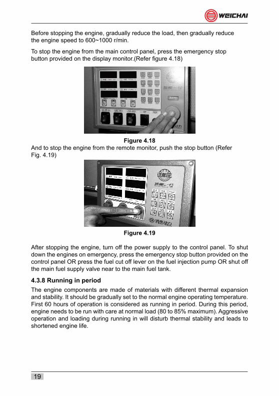
Before stopping the engine, gradually reduce the load, then gradually reducethe engine speed to 600~1000 r/min.
To stop the engine from the main control panel, press the emergency stopbutton provided on the display monitor.(Refer figure 4.18)
Figure 4.18And to stop the engine from the remote monitor, push the stop button (ReferFig. 4.19)
Figure 4.19
After stopping the engine, turn off the power supply to the control panel. To shut down the engines on emergency, press the emergency stop button provided on the control panel OR press the fuel cut off lever on the fuel injection pump OR shut off the main fuel supply valve near to the main fuel tank.
4.3.8 Running in periodThe engine components are made of materials with different thermal expansion and stability. It should be gradually set to the normal engine operating temperature. First 60 hours of operation is considered as running in period. During this period, engine needs to be run with care at normal load (80 to 85% maximum). Aggressive operation and loading during running in will disturb thermal stability and leads to shortened engine life.

20
4.4 Regular operationPractice the daily inspection and maintenance for trouble free, safe and reliableengine performance (refer table 4.1)
DAILY INSPECTION AND MAINTENANCE
BEFORE START UP► Ensure oil level is correct.► Ensure coolant level is correct.► Ensure sufficient fuel level in the fuel tank.► Drain out water and impurities from fuel water separator and filter respectively► Ensure the belt tightness is sufficient, and that there is no crack, peel off etc.► Ensure no leakage from any of the fluid systems – coolant, oil, fuel, etc.► Ensure all electrical control system is in order and ensures the battery is healthy.► Ensure all the hoses are free from leakage, not developed any cracks, etc.► Ensure sufficient greasing wherever required (water pump, belt tensionerpulley etc.).
AFTER STARTING
► Keep the engine on idle speed for 2 -3 minutes and let it warm up.
► Ensure no leakage in the fluid system – Coolant, oil etc.
► Observe the oil pressure, oil temperature, coolant temperature are normal.
► Observe the engine operation and ensure no abnormal noise, vibration, etc.
► Observe the exhaust smoke is normal.
► Ensure no variation in engine speed (hunting etc.)
Table 4.1
Record basic engine parameter during early life of the engine. Monitor it every routine inspection and maintenance. Gradual drop in oil pressure is the indicator of progressive wear in inter-nal parts. If any abnormal change in parameter is noticed, shutdown the engine immediately. Find out and rectify the cause of trouble before restart. Refer table 4.2 for specified fit and clear- ance values

21
4.4.1 Engine starting• Before starting the engine confirm the fuel throttling and gear box engaging
lever is in NEUTRAL position (refer figure 4.20).• Do not touch the throttle or throttle lever while starting the engine. Engine should
start and stabilize in the specified idle speed without any aid.• If engine has stopped by pressing emergency button, release the button before
restart.• If the engine is stopped by shutting main fuel supply valve, open the fuel valve
before the starting attempt.• Always ensure safe coolant level in the heat exchanger expansion tank.
Figure 4.204.4.2 Engine warm upAfter the engine is started, it takes a while for the lubricating oil to re-establish the required oil film in between moving parts. The most appropriate clearance conditions between moving parts are obtained only when the engine parts reach the normal operating temperature. Gradually accelerating the engine during warm up will avoid abnormal wear and tear of liner, piston rings and bearings caused by insufficient lubrication.
4.4.3 Monitoring the engine oilAlways maintain the correct oil level in the sump. Too high and very low level will be a threat to engine safety. During warm-up period, engine should be loaded gradually, until it reaches the temperature of 60°C. Required oil pressure will ensure enough oil flow to various engine sub-assemblies and parts. Oil pressure will vary depending on viscosity and oil viscosity depends on temperature. Normal oil pressure at 105°C should be between 300-350 KPa
22
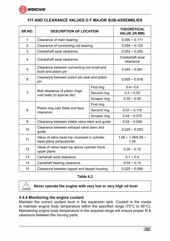
FIT AND CLEARANCE VALUES O F MAJOR SUB-ASSEMBLIES
SR.NO. DESCRIPTION OF LOCATION THEORETICAL VALUE (IN MM)
1 Clearance of main bearing 0.095 ~ 0.171
2 Clearance of connecting rod bearing 0.059 ~ 0.135
3 Crankshaft axial clearance 0.052 ~ 0.255
4 Crankshaft axial clearance Crankshaft axial clearance
5 Clearance between connecting rod small end bush and piston pin 0.045 ~ 0.061
6 Clearance between piston pin seat and piston pin 0.005 ~ 0.018
7 Butt clearance of piston rings- cold state (in special die)
First ring 0.4~ 0.6
Second ring 0.3 ~ 0.55
Scraper ring 0.35 ~ 0.55
8 Piston ring cold State end face clearance
First ring
Second ring 0.07 ~ 0.115
Scraper ring 0.04 ~ 0.075
9 Clearance between intake valve stem and guide 0.02 ~ 0.048
10 Clearance between exhaust valve stem and guide 0.025 ~ 0.053
11 Value of valve head top recessed in cylinder head plane exhaust/inlet
1.08 ~ 1.48/0.85 ~ 1.05
12 Value of valve head top above cylinder block upper plane 0.05 ~ 0.10
13 Camshaft axial clearance 0.1 ~ 0.4
14 Camshaft bearing clearance 0.04 ~ 0.12
15 Clearance between tappet and tappet housing 0.025 ~ 0.089
Table 4.2
Never operate the engine with very low or very high oil level
4.4.4 Monitoring the engine coolantMaintain the correct coolant level in the expansion tank. Coolant is the media to maintain engine body temperature within the specified range (75°C to 95°C). Maintaining engine body temperature in the required range will ensure proper fit & clearance between the moving parts.
CAUTION

23
During operation, coolant level must be between the low and high marks of the tank level.
If there is no coolant in emergencies, slowly add coolant with temperature not too lower from the coolant filler, until the coolant becomes over-flown. Start engine and continue to add coolant with engine running at 1000 r/min, till it is full and the level becomes stable. Finally cover the filler cap.
4.4.5 Monitoring the exhaust gasHealthy engine operation and performance can be properly pointed out bythe engine exhaust. Poor mechanical adjustments, dirty air cleaner, usingpoor grade fuel or over-fueling may cause a smoky exhaust. Action shouldbe taken immediately to treat it. If any serious color change is noticed, stopthe engine and carry out the inspection procedure. Refer table 4.3 for mainparameters of analyzing the exhaust gas.
EXHAUST GAS QUALITY MONITORINGSR.NO COLOR REASON
1 Clear Healthy combustion system
2 Grey Poor combustion quality (faulty injector or injection pump, weak compression, etc.)
3 Dark grey
Poor combustion quality (one or more system failed - choked air filter, weak turbocharger, chocked intercooler, failed injector or fuel injection pump etc.)
4 Blue Engine oil burning in combusting chamber
5 White Water ingresses in fuel/combustion system
Table 4.34.4.6 Engine shutdown
Engine should run on idle speed for 3~4 minutes before shutting down. Running on idle speed will ensure uniform heat dissipation and enough cooling and to lubrication to high temperature areas like turbocharger & combustion chamber etc. However excessive idling should be avoided.
Caution for operation
After starting the engine, let it run at idle speed for a few minutes (2-3 minutes), then gradually increase the speed to 1000~1200r/min, and apply a partial load.
Apply full load only when the fresh water outlet temperature is higher than 60°C, and oil temperature is higher than 50°C. Increase the load and speed gradually. Avoid sudden application or removal of load.

24
In normal operation of the engine, it is allowed to operate continuously at described rated speed and power. However, the permissible over-speed is 103% of the rated speed and over-load is 110% of the rated power. Duration for the above permissible over-speed/load is 1 hour within every 12 hours.
Do not check oil or coolant level while engine is running
OK OK
Mixture of different grade or brands of engine oil is strictly prohibited. During operation, always pay attention to the parameter values displayed on the panel and observe the performance of various systems. Carefully check the diesel engine for water leakage, air leakage, oil or fuel leakage. Stop engine if any leakage is found, and rectify the trouble.
Engine economy balancing tips• It is most economical to operate the engine at medium speed -ranging from
60% to 90% of rated speed.• The engine power is increased with the increase of the speed. Rated power is
obtained at rated speed.• According to seasons, select the specified brand of fuel, oil and coolant in
compliance with requirements.• Carry out the inspection and maintenance according to schedule (see Section
IV of this manual).• During operation, maintain engine parameter as per table 4.3
Any sudden rise in oil/coolant temperature which is not caused by increase in load is a possible system failure warning and should be investigated thoroughly at once
CAUTION
CAUTION

25
PARAMETERS TO MONITOR DURING REGULAR OPERATIONSR.NO PARAMETER UNIT VALUE REMARK
1 Oil pressure in main oil passage KPa 350~550 Rated speed
and power
2 Oil pressure in main oil passage KPa ≥100 Idle speed
3 Oil temperature in oil sump °C 85~115
4 Engine oil temperature at normal operation °C 75~105
5 Coolant outlet temperature at normal operation °C 70~95 It should not
exceed 95°C
6 Exhaust gas temperature after gas turbine °C <550
7 Inlet air temperature after air cooler °C 55 ± 5
Table 4.4
Before most of the failure, engine will develop early warning in the from of abnormal sound, changes in parameter and performance or engine appearance. Close monitoring of the engine will help to detect the failure in the preliminary stage. Few signs, to look out for are as below:
‒ Leakage of oil fuel, coolant, compressed air or exhaust gas ‒ Color change in exhaust gas ‒ Rise/drop of pressure and temperature ‒ Excessive vibration ‒ Sudden unusual noise ‒ Misfiring of engine ‒ Rise in oil/fuel consumption ‒ Power loss
Operation of diesel engine in winter
1. Fuel: Select and use the diesel of different brands according to the outdoor temperature in winter.
2. Oil: Select the oil with different viscosities according to different seasons.
3. Coolant: Select and use different brands of anti-freeze additive and add additive in different quantity into the cooling system according to the outdoor temperature.

26
4. Starting: In winter, use the auxiliary starter if required. It is allowed to run the engine at higher speed and apply load after attaining the normal oil pressure and water temperature.
Battery: Before beginning of winter season, check the electrolyte level, specific gravity and cell voltage. If the diesel engine is not used for a long time and ambient temperature is very low, then remove the battery and store it in a warm room.Shutdown: When stopping the engine in cold weather, first remove its load, then the run the engine at idle speed for 3~4 minutes, stop the engine only after all temperatures drop down. Do not drain off coolant with anti-freeze additive after the engine is stopped. If the coolant is not added with the anti-freeze additive, then it is necessary to open water drain valve and completely drain off all coolant. This will prevent damages caused to the engine due to freezing

27
SECTION - VPERIODIC MAINTENANCE
Weichai engines are designed for high reliability and long life. The engines are built to withstand marine operational environment. Preventive maintenance is the cost effective and economical way to reduce the operational cost of a diesel engine. If the preventive maintenance is carried out as per quality and schedule, downtime and costly breakdowns can be eliminated.
The maintenance schedule is defined by the actual operating environment of the engine. The maintenance schedule given in table 5.1 is for ideal operating condition. In case of heavy dust or special situation, the frequency of the maintenance must be increased.
5.1 Safety precautionsBefore performing maintenance operations the engine operator must carefully read and understand the instructions provided in this section. The operator must be aware of and strictly follow the relevant operating instruction and safety precaution, accident preventive measures, and obey generally recognized industrial safety measures.
5.2 Importance of periodic maintenanceLife of the engine is mainly based on quality of fuel, lube oil and coolant, routine inspection and maintenance and the hours of operation. Every routine inspection and maintenance is designed to monitor the engine health and performance in a desired interval and prevents unexpected breakdown. Proper maintenance reduces the number of accidents due to poor machine performance and helps extend the life of the engine. Refer table 5.1 for recommended maintenance interval.
5.3 Replacement of parts and componentsAs far as operation of parts and components is concerned, the customer must follow relevant specifications of the engine manufacturer and pay attention to relevant terms and conditions. If any parts and components are to be replaced during repair, then it is required to follow regulations concerning the replacement of parts and components specified by manufacturer.
It is allowed to use only genuine spare parts on the engineprocured from a reliable outlet of the engine manufacturer. If thecustomer or the service center has installed non-genuine spare parts and sub-assemblies, the supplier should take the responsibility and bear all cost damage to engine which may subsequently occur and damage and injury to persons and equipment within the legal scope of product warranty.
CAUTION
28
5.4 Reliability of partsPrior to replacing any parts and components, customer must make sure that the new parts and components to be installed are made by the original engine manufacturer or authorized cooperative production factories, and use necessary measuring instruments to check and make sure they meet the relevant technical specifications. Non-genuine spare part components may lead to physical damage of the components, functional safety of the engine, human injury or severe equipment damage.
5.5 Safe use of oil and fuel in a diesel engineHazardous working media like lubricant and fuel are explosive, flammable, toxic and corrosive. They are also harmful to human health. Following measures must be taken while handling the hazardous materials.• Avoid direct contact with hazardous working media.• Clothes contaminated by hazardous working media must be changed as soon
as possible.• Only use neutral soap to wash the part of body where it is contaminated by oil
or fuel (removal by using fine sand or solvent is not allowed).
5.6 Disposal of used oil or fuelPolluting the environment is a punishable offence by the government.It is the responsibility of customer to make necessary arrangements to properly dispose the used oil and other hard waste generated during engine operation.Collect used oil or contaminated fuel in special containers and dispose it through approved disposing vendors.

29
PERIODIC MAINTENANCE CHART
Maintenance Description
First Inspection
Periodical Inspection Scheduled maintenance interval
First 50 Hours Every 300 Hours Level 1 Level 2 Level 3 Level 4
Every 600 Hours
Every 1500 Hours
Every 3000 Hours
Every 6000 Hours
Engine oil Replace Replace Replace Replace Replace Replace
Oil filter Replace it on every oil change
Fuel filter Replace Replace Replace Replace Replace
Fuel water separator Replace Replace Replace Replace
Coolant Check & top up if required
Check & top up if required
Check & top up if required
Check & top up if required Replace Replace
Clamps & bracket Check &re tight Check &re tight Check &re
tightCheck &re
tightCheck &re
tight Replace
Hoses & belts Check Check Check Check Check Replace
Air filter Check &clean Replace Replace Replace Replace
Injector Calibrate Replace nozzle
Valve clearance Check
Check & Adjust if required
Check & Adjust if required
Starter motor & generator Check Check Check Check Check Service
Parameter monitoring Record it after every periodic maintenance
Crankshaft axial clearance
Check & record
1. Above maintenance interval is applicable only when the maintenance procedure is followed from the first Inspection onwards and used the Weichai recommended products.
2. It is suggested to operate the engine at operating temperature once in a week for minimum 5 minutes3. Detailed maintenance schedule can be availed from ASCs on request. 4. Recommended lubricant: SHELL RIMULA R45. Recommended coolant: FLEET GUARD CG
Table 5.1
5.7 Periodic Maintenance instructions5.7.1 Check air filterCleaned air is playing a major role for the optimum engine performance and in deciding the overhauling life. Periodically check, clean and replace the air filters to ensure optimum performance and maximum overhauling life.
It is not allowed to use the engine without air filter, otherwise the dust and impurities will cause aggressive wear of the internal parts.
30
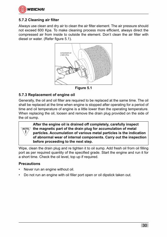
5.7.2 Cleaning air filterAlways use clean and dry air to clean the air filter element. The air pressure should not exceed 600 Kpa. To make cleaning process more efficient, always direct the compressed air from inside to outside the element. Don’t clean the air filter with diesel or water. (Refer figure 5.1).
compresed air(<600 kPa)
Figure 5.1
5.7.3 Replacement of engine oilGenerally, the oil and oil filter are required to be replaced at the same time. The oil shall be replaced at the time when engine is stopped after operating for a period of time and oil temperature of engine is a little lower than the operating temperature. When replacing the oil, loosen and remove the drain plug provided on the side of the oil sump.
After the engine oil is drained off completely, carefully inspect the magnetic part of the drain plug for accumulation of metal particles. Accumulation of various metal particles is the indication of abnormal wear of internal components. Carry out the inspection before proceeding to the next step.
Wipe, clean the drain plug and re tighten it to oil sump. Add fresh oil from oil filling port as per required quantity of the specified grade. Start the engine and run it for a short time. Check the oil level, top up if required.
Precautions• Never run an engine without oil.• Do not run an engine with oil filler port open or oil dipstick taken out.

31
5.7.4 Replacement of oil filterUse the filter wrench to loosen the filter and remove it by hand refer figure 5.2 & 5.3. Use a suitable tray under the filter location to collect oil spillage before removing the filter.
Figure 5.2 Figure 5.3
Let the oil drain completely from the filter housing refer figure 5.4. Wipe the sealing surface with a clean cloth, and apply fresh oil to the seal ring, then position the filter on the housing by hand and tighten it with the help of filter wrench refer figure 5.5& 5.6
Figure 5.4 Figure 5.5
Figure 5.6

32
Run the engine for a short time, during running check and ensure no leakage from the filter sealing and from the oil drain plug refer figure 5.7
OK
Figure 5.7
Stop the engine; check the tightness of filter for reliability, if necessary. Measure the oil level with the help of the oil dipstick.
To get correct oil level, always check it 5 to 10 minutes after stopping the engine
5.7.5 Cleaning of oil gas separatorOil gas separator is functioning as a ventilator for crank case to release the flugases by controlling the oil wastage/ consumption/ spillage. Periodic maintenance and monitoring will help us to understand the health of combusting system.
5.7.6 Replacement of fuel filterUse the filter wrench to loosen the filter and remove it by hand. Use a suitable tray under the filter location to collect diesel spillage before removing the filter. Loosen and remove the filter. Refer figure 5.8 & 5.9.
Figure 5.8 Figure 5.9
Let the fuel drain completely from the filter housing. Wipe the sealing surface with a clean cloth, and apply fresh oil to the seal ring, then tighten new diesel filter with the filter wrench

33
5.7.7 Air bleeding from fuel systemAfter every filter change and maintenance of engine fuel system, or air entered into the system, check the whole fuel system and bleed out the air from the system.(Refer figure for 5.10 & 5.11 for main air bleeding points in the fuel system)
Figure 5.10 Figure 5.11
5.7.8 Adjustments and replacement of V-BeltTwo B type V belts used to drive the fresh water pump and the charging alternator. Refer Fig. 5.12 Check the belt tension regularly; do neccessary adjustments if required. If the belt tension is incorrect, it will lead to various troubles like high water, poor charging of battery etc. While checking, if the belt is flexible by more than 10 mm (When applying a strong force by thumb - refer Fig. 5.13) the belt needs adjustment. The belt tension can be adjusted from the alternator mounting support (refer Fig. 5.14) Replace the belt(s) if any damage (peel off, crack, rib crank or wear etc.) is noticed. Refer periodic maintenance for belt replacement interval.
Figure 5.12 Figure 5.13
Figure 5.14
34
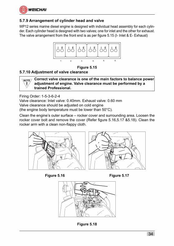
5.7.9 Arrangement of cylinder head and valveWP12 series marine diesel engine is designed with individual head assembly for each cylin-der. Each cylinder head is designed with two valves; one for inlet and the other for exhaust. The valve arrangement from the front end is as per figure 5.15 (I- Inlet & E- Exhaust)
I
1 2 3 4 5 6
E I E I E I E I E I E
Figure 5.155.7.10 Adjustment of valve clearance
Correct valve clearance is one of the main factors to balance power adjustment of engine. Valve clearance must be performed by a trained Professional.
Firing Order: 1-5-3-6-2-4Valve clearance: Inlet valve: 0.40mm. Exhaust valve: 0.60 mmValve clearance should be adjusted on cold engine(the engine body temperature must be lower than 50°C).Clean the engine’s outer surface – rocker cover and surrounding area. Loosen the rocker cover bolt and remove the cover (Refer figure 5.16,5.17 &5.18). Clean the rocker arm with a clean non-flappy cloth.
Figure 5.16 Figure 5.17
Figure 5.18

35
Open the inspection window on the flywheel and match the OT mark to the pointer (Refer figure 5.19).
0
Figure 5.19
Check and confirm compression TDC of the 1st cylinder. Adjust the Clearance in the following order. (Refer figure 5.20 & 5.21)
CYL. NO 1 2 3 4 5 6STEP- 1 I E I - - E I - - E - -
Figure 5.20 Figure 5.21
Rotate the engine 360° - match the OT mark to the pointer. Adjust theclearance in the following order. (Refer figure 5.22).

36
Figure 5.22
CYL. NO 1 2 3 4 5 6STEP- 2 - - - E I - - E I - I E
Once the adjustment is completed, refit the rocker cover. Pay attention to the cover gasket for damages. If any damage is noticed, replace it with the new one.
5.8 Maintenance recommendationThe major maintenance is depends on main factors like routine inspection and maintenance, quality of fuel, lubricant and coolant, atmosphere etc. Considering the ideal situation, periodic maintenance chart is prepared (refer table 5.1).
Refer table 5.3 for torque values and tightening sequence and table 5.4 for list of sealants and locking products used for engine maintenance.

37
RECOMMENDED MAINTENANCE SCHEDULE
SR.NO
RELATEDSYSTEM OR
SUBASSEMBLY
SR.NO DESCRIPTION
MAINTENANCE INTERVAL (HOURS)
ABBREVIATIONS: A- ADJUST, C- CLEAN, I-INSPECTION, M- MONITOR, R- REPLACE, S-SERVICE,
CAL- CALIBRATE, MS- MAJOR SERVICE
50 Hrs.
300 Hrs.
600 Hrs.
1500 Hrs.
3000 Hrs.
6000 Hrs.
12000 Hrs.
1 LUBE OIL SYSTEM
1 LUBE OIL R R R R R R R
2 STRAINER C
3 PUMP M M M M M M S&I
4 COOLER C&I C&I C&I
5 FILTER REPLACE ON EVERY OIL CHANGE
6 OIL FILTER SEAT C&I
7 PRESSURE SENSOR I I CAL
8 TEMPERATURE SENSOR I I CAL
9 PRESSURE RELIEF VALVE I CAL
10 OIL GALLERY C&I
11 TURBO CHARGER OIL SUPPLY LINE I I I
12 TURBO CHARGER OIL RETURN LINE I I I
13 OIL MEASURING GAUGE (DIP STICK) I I
14 GASKETS & SEALS REPLACE EVERY TIME WHEN REMOVED
2 FUEL SYSTEM
1 FUEL FILTER M R R R R R R
2 FUEL FEED PUMP M M M M MS MS MS
3 FUEL INJECTION PUMP M C&I CAL MS&CAL
4 INJECTOR NOZZLE M R R R
5 RETURN LINE FLEXIBLE HOSE R R R
6 GASKETS & SEALS REPLACE EVERY TIME WHEN REMOVED
3 AIR INTAKE SYSTEM
1 AIR FILTER I C&I C&I C&I R R R
2 AFTER COOLER M M M M C&I C&I C&I
3 AIR INTAKE MANIFOLD I I I
4 HOSES AND CLAMPS I I I I I R R
5 GASKETS & SEALS REPLACE EVERY TIME WHEN REMOVED
4 EXHAUST SYSTEM
1 EXHAUST MANIFOLD I I I
2 TURBO CHARGER I I&S MS
3 FASTNERS R R
4 GASKETS & SEALS REPLACE EVERY TIME WHEN REMOVED

38
5JACKET
COOLING SYSTEM
1 COOLANT C&T C&T C&T C&T C&T R R
2 COOLANT WATER PUMP I S&I
3 WATER JACKET I C&I
4 THERMOSTAT M R R R
5 HEAT EXCHANGER M M M M C&I C&I C&I
6 CRANK CASE WATER JACKET C&I C&I
7 DUMMEY FOR WATER JACKET M C R
8 HOSES AND CLAMPS M M M M R R R
9 FUEL TANK C&I C&I C&I
10 FLEXIBLE HOSES AND CLAMP R R R
11 FUEL WATER SEPARATOR M M M R R R R
12 GASKETS & SEALS REPLACE EVERY TIME WHEN REMOVED
6 CYLINDER HEAD
1 INTAKE VALVE AND EXHAUST VALVE I I R
2 VALVE SEAT I I R
3 VALVE GUIDE I I R
4 COLLETS I I R
5 SEALS R R R
6 SPRING SET I I I
7 WATER JACKET DUMMY I I R
8 WATER JACKET PRESSURE TESTING I I
9 GASKET & SEAL R R R
10 FASTNERS
11 GASKETS & SEALS REPLACE EVERY TIME WHEN REMOVED
7 VALVE TRAIN
1 PUSH ROD I I
2 ROCKER ARM ASSEMBLY I I
3CHECKING AND ADJUSTING VALVE CLEARANCE
C&A C&A C&A C&A
8 MOVING ELEMENT
1 PISTON I R
2 PISTON PIN I R
3 PISTON RING SET R R
4 CYLINDER LINER R R
5 CONROD BOLT EVERY TIME WHEN IT IS LOOSENED
6 CONROD SMALL END BUSH I R

39
8 MOVING ELEMENT
7 CONROD BIG END BEARING I R
8 CONROD I I
9
CRANK CASE- CAM SHAFT - CRANK SHAFT - GEAR TRAIN
1 MAIN BEARINGS & THRUST BEARINGS R
2 CAM BUSH BEARING R
3 BEARINGS RELATED TO GEAR TRAIN R
4 OIL SEALS R R
5 TAPPET I I
6 CAM SHAFT I
7 CRANK SAHFT I
8 CAM & IDLE GEAR I
9 ROLLER BEARING R
10 FASTNERS I
10 OTHERS SUB ASSEMBLIES
1 FAN BELT M M R R R R
2 BELT TENSIONOR PULLEY R R
3 FLEXIBLE HOSES AND CLAMP C C C C C R R
4 SET OF O RINGS AND GASKETS REPLACE EVERY TIME WHEN REMOVED
5 STARTER MOTOR M M M M I&S I&S
6 ALTERNATOR M M M M I&S I&S
7 DISPLAY MONITOR M M M M I&S I&S
8 WIRE HARNESS M M M M I&S I&S
9 FUEL SHUT OFF SOLINOID M M M M I&S I&S
10 ENGINE STOP SOLINOID M M M M I&S I&S
11 VIBRATION DAMPER M M M M I&S I&S
12 GAS OIL SEPARATOR C C C I&S
Table 5.2Replacement period of engine oil varies according to the operating conditions as below.
Normal operating condition (the above-listed is normal operation condition, when the oil consumption is normal): the ambient temperature is normal, and fuel with sulfur content lower than 0.5% (by weight) is used. Adverse operating condition (oil consumption is high):
1. In tropical climate or cold zone (temperature exceeds +30° or lower than -10°), the oil drain period shall be half of that un der normal operation condition.
2. When sulfur content of fuel with is 0.5~1.5%, the oil drain period shall be half of that under normal operation condition.
3. In adverse operating condition with A+B, the oil drain period shall be one fourth of that under normal operation condition.

40
TIGHTENING TABLE AND TORQUE VALUES FOR MAIN FASTENERS
DESCRIPTIONS SPECIFICATIONS (SIZE – GRADE) REQUIREMENTS
ALLOWABLE TIMES
TO REUSE
Main bearing bolt M18X169 - 10.9 140N.m+210° 2
Crankcase secondary bolt M8X 25 - 8.8M8X210 - 8.8
8N.m+30 2
Cylinder head main bolt M14X185 - 10.9 60N.m+2×120° 3
Cylinder head secondary bolt
M12×1.5X195 - 8.8 20+10N.m Seal with Loctite 262 Sealant 3
Cylinder head secondary nut
25N.m+2×120° 3
Crankshaft pulley bolt M12×1.5X75 - 10.9 45N.m+135° 2
Bolt for tensional vibration damper
M10X30 - 8.8 15N.m+30° 2
Flywheel bolt M16×1.5X120-10.9
105N.m+270° 2
Connecting rod bolt M14×1.5X67.5 - 10.9
115N.m+90°(Manual
tightening)0
80N.m+153°(Automatic tightening)
Idler gear bolt pin M12×1.5X90 - 10.9 105N.m 0
Injector clamping bolt M8X50 - 8.8 8N.m+90 3
Camshaft gear bolt M8X30 - 8.8 8N.m+120° 2
Piston cooling injector bolt M10X25 30N.m 0
Exhaust manifold bolt M10X65 15N.m+60° 2
Standard torque table
Bolt size Grade Torque value Grade TorqueValue
Standard M6 bolt 8.8 8 Nm 10.9 13 Nm
Standard M8 bolt 8.8 22 Nm 10.9 31 Nm
Standard M10 bolt 8.8 39 Nm 10.9 58 Nm
Standard M12 bolt 8.8 70 Nm 10.9 100 Nm
Table 5.3

41
1
2
4
5
9
8
6
3
7
10
14
11
Main bearing bolts tightening sequence
Cylinder head main Bolts tightening sequence
Cylinder head auxiliary bolts tightening sequence

42
LIST OF SEALANTS AND THREAD LOCKING COMPOUNDS USED FOR ENGINE MAINTENANCE
SR. NO DESCRIPTION COLOR USAGE AND APPLICATION
1 Molykotte Pulver Black
Apply it to smooth metal surface to prevent seizing For example: apply it on the outer surface of cylinder sleeve.
2 Molykotte G.u. plus
Dark Grey
Take the lubricating function before the lubricating oil pressure is established, For example: apply on inlet valve rod.
3 Loctite242 Blue
Apply it on the thread surface for fixing, avoid the looseness caused by shake, with medium strength, For example, apply on the thread of main oil passage pressure limiting valve.
4 Loctite262 Red
Apply it on the thread outer surface for locking, sealing and prevention of looseness due to vibration, in high strength. For example: Cylinder head bolt threaded part
5 Loctite275 GreenApply on the surfaces on pipe and junction for fixing; For example: apply on the surface of water outlet pipe and heating water inlet pipe.
6 Loctite510 Red(orange)
Apply it on the bright metal surface to play a sealing role For example: apply it to the faying surface between cylinder block and crankcase
7 Loctite277 Red
Apply on cavity or passage for sealing between element and hole. For example: Bowl shaped plug matching cylindrical surface
8 Loctite648 GreenApply it on the bright metal surface to play fixing role For example: Tension pulley bearing bore and shaft outer surface.
Table 5.4

43
TROUBLE SHOOTING GUIDE FOR WP12 MARINE DIESEL ENGINE
detsujda eb ot sdeen rotcejni leuF
derocs ro nrow si notsip ro eveels rednilyC
tcerrocni si gnimit evlav dna noitcejni leuF
esool si tlob gnitnuoM
strap gnivird htiw dengila ton si enignE
gib oot si hsalkcaB
evird raeg ni htoot nekorb raeg ynam ro enO
degamad si gniraeb dor gnitcennoc ro gniraeb niaM
deluahrevo eb ot sdeen enignE
noitadnemmocer htiw ecnailpmoc ni ton si edarg liO
eruliaf ni si evlav gnitsujda erusserp lio
wol si level lio ro lio skcal esacknarC
deggolc si reniarts noitcus liO
dekcolb si egassap liO
desaerg si notsiP
ytrid si retlif liO
edisnidna edistuo skael liO
ytrid si retlif leuF
noitcnuflamni si retimil ekomS
detsujdasim si pmup noitcejni leuF
reporpmi si elzzonnoitcejni fo gnizimotA
leuf ni retaW
wol oot si ronrevog fo deeps hgiH
dettif ylreporpmi si ylbmessa thgiew ronrevoG
delbmessa ylreporpmi si gnirps eldI
reporpmi si tnemtsujda msinahcem elttorhT
dekcarc si rotcejnI
si ylbmessathgiew ronrevoG
esool si rotcennoc nruter leuf ro telni rotcejnI
nekorb si tfahs evird
pmup noitcejni leuF
nekorb si tfahs evird pmup noitcejni leuF
dekcolb si ecifiro elzzoN rotcejnI
edistuo skael leuF
deggolc si epip telnI
telni otni skael riA
roop si ytilauq leuF
Lacks fuel
tcerrocni si ecnaraelc evlav teltuo dna telnI
staes evlav ro sevlav teltuo dna telnI ykaeL
dekcohc si rebmahc rosserpmoc regrahc obruT
ekatni dna regrahc obrut neewteb ni ssol ria desserpmoCmanifold
)erutarepmet ria hgih( .ria esnsed woL
erusserp kcab tsuahxe hgiH
dekcohc si metsys ekatni riA /ria tneiciiffusnI
▲
▲
▲
▲
▲
▲
▲
▲
▲
▲
▲
▲
▲
▲
▲
▲
▲
▲
▲
▲
▲
▲
▲
▲
▲
▲
▲
▲
▲
▲
▲
▲
▲
▲
▲
▲
▲
▲
▲
▲
▲
▲
▲
▲
▲
▲
▲
▲
▲
▲
▲
▲
▲
▲
▲
▲
▲
▲
▲
▲
▲
▲
▲
▲
▲
▲
▲
▲
▲
▲
▲
▲
▲
▲
▲
▲
▲
▲
▲
▲
▲
▲
▲
▲
▲
▲
▲
▲
▲
▲
▲
▲
▲
▲
▲
▲
▲
▲
▲
▲
▲
▲
▲
▲
▲
▲
▲
▲
▲
▲
▲
▲
▲
▲
▲
▲
▲
▲
▲
▲
▲
▲
▲
▲
▲
▲
▲
▲
▲
▲
▲
▲
▲
▲
▲
▲
▲
▲
▲
▲
▲
▲
▲
▲
▲
▲
▲
▲
▲
▲
▲
▲
▲
▲
▲
▲
▲
▲
▲
▲
▲
▲
▲
▲
▲
▲
▲
▲
▲
▲
▲
▲
▲
▲
▲
▲
▲
▲
▲
Oth
ers
Eng
ine
knoc
king
Abo
rmal
met
al k
nock
ing
soun
dE
xces
sive
gea
r mes
hing
noi
se
Abn
orm
al v
ibra
tion
of e
ngin
e
Fuel
sys
tem
Lubr
icat
ing
Oil
syst
em
Coo
ling
wat
er te
mpe
ratu
re is
ver
y lo
wC
oolin
g w
ater
tem
pera
ture
is v
ery
high
Oil
tem
pera
ture
is v
ery
high
Spe
ed h
untin
g in
idle
spe
ed
Mai
n be
arin
g an
d co
nnec
ting
rod
bear
ing
are
wor
n ou
tV
alve
and
val
ve g
uide
are
wor
n
Eng
ine
is s
hutd
own
sudd
enly
Spe
ed is
not
sta
ble
Oil
cons
umpt
ion
is to
o hi
ghH
igh
carb
on d
epos
its in
the
cran
kcas
e w
all
Fuel
dilu
tion
in e
ngin
e oi
l O
il pr
essu
re is
low
Hea
vy b
lack
sm
oke
at lo
w lo
adIn
suffi
ent p
ower
or n
o po
wer
Fail
to re
ach
the
rate
d sp
eed
Fuel
con
sum
ptio
n is
hig
hTr
oubl
e in
rais
ing
and
low
erin
g th
e
Valv
e m
echa
nism
Diff
icul
t or u
nabl
e to
sta
rtE
ngin
e is
shu
tdow
n so
on a
fter
Hea
vy b
lack
sm
oke
at id
le s
peed
PROBABLE REASONFAILURE
FAIL
UR
E
SYM
PTO
M

44
SECTION - VISPECIFICATIONS FOR LUBRICANT, COOLANT AND FUEL
6.1 Lubricant6.1.1 The functioning of lubricating oil in a diesel engineThe lubricating oil used in the engine must be multifunctional. It must performthe primary functions of:1. Lubrication: Basic function is to reduce friction and minimize the wear and
tear. The engine oil to form a film between the moving parts (such as bearings, pistons, piston rings, cylinder liners and the valve train) and ensure sufficient lubrication between the moving parts.
2. Cooling : Acts as a media for high heat transfer (from combustion chamber) and protecting the moving parts from overheating.
3. Detergency: Cleaning pistons and preventing sludge build-up on internal surfaces
4. Prevention from corrosion: Corrosion prevention by neutralizing the acid and protecting the components from atmospheric humidity by creating a layer.
5. Sealing: By filling in the uneven surfaces in the cylinder wall, valve stems and turbocharger oil seals.
6.1.2 Engine oil consist ofEngine oil consists of base oil and additives. Base oil is the most basic raw materials of engine oil and additives are added for enhancing the oil properties which is suited for diesel engine applications. Basic additives are viscosity modifiers, anti-wear additives, detergents, dispersant and antioxidant etc.
6.1.3 Why oil to be drained?Engine lubricating oil must be drained when it can no longer perform its functions in an engine. Oil doesn’t wear out, but it becomes contaminated/ degraded to the point that it can no longer satisfactorily protect the engine. The engine oil degradation is a normal result of engine operation, where oil properties changed mainly because of reaction to the combustion by products.
6.1.4 How engine oil performance getting deteriorated1. By-products of Engine Combustion: Soot from partially burned fuel will
con-taminate the fresh oil and over a period of time, viscosity of the oil will increase.
2. Base (BN) additives become neutral due to reaction with acid, produced during combustion process.
3. Varnish and sludge which are formed as a result of the oxidation of the oil as it breaks down or decomposes which leads to oil thickening

45
4. Contamination due to dirt entering the engine through the atmospheric air and bad fuel.
5. Other additive depletion due to reaction which will affect the performance of oil.
The engine oil becomes inefficient after the recommend hours. Hence, it is necessary to replace.
6.1.5 Oil performance classification systemFollowing are the organizations designing and approving oil classification and specification standards.API (American Petroleum Institute)ACEA (Association des Constructeurs Europeans d’Automobiles - European)ASTM (American Society for Testing Materials)JASO (Japanese Automobile Standards Organization)
Sr. No Category Year Service Status
1 CJ-4 2006
For high speed, four stroke engines to meet 2007 emission standards. Use diesel fuels ranging in sulphur content up to 500 ppm (0.05% by weight Current). DPF and other emission device compatible. API CJ-4 oils are backward compatible.
2 CI-4 2002
For high-speed 4 stroke engines to meet exhaust emission standards implemented in 2002. EGR and diesel fuels sulphur up to 0.5%. Can be used in place of CD, CF, CF-4 and CH-4 oils.
Current
3 CH-4 1996
For high-speed, four stroke engines designed to meet 1998 exhaust emission standards. Diesel fuels sulphur content up to 0.5% weight. Can be used in place of CD, CE, CF-4, and CG-4 oils.
Current
4 CF 1994
For off-load, indirect injected and other diesel engines including those using fuel with over 0.5% sulphur. Can be used in place of CD oils.
Current
Table 6.16.1.6 SAE viscosity recommendationsThe viscosity of oil is a measure of its resistance to flow. The Society of Auto- motive Engineers has classified engine oils in viscosity grades:• Oils that meet the low temperature [0°F (-18°C)] requirement, carry a grade
designation with a “W” suffix.• Oils that meet both the low and high temperature requirements are referred to
as multi grade or multi viscosity grade oils.

46
Multi graded oils are generally produced by adding viscosity index improver additives to retard the thinning effects that the low viscosity base oil will experience at engine operating temperatures. Multi graded oils that meet the requirements of the API classifications, are recommended for use in engines.It is recommended to use the multi graded lubricating oil with the viscosity grade as table 6.2.
GUIDELINES TO SELECT OIL VISCOSITY ACCORDING TO AMBIENT TEMPERATURE
Engine oil
SAE viscosity grade Applicable ambient temperature range(°C)
5W/30 -30~35
10W/30 -25~35
15W/40 -20~40
20W/50 -15~50
Gear oil
85W/90 -15~49
80W/90 -25~49
85W/140 (above 85W/90) -15~49
Table 6.26.2 Engine oil recommendations for Weichai enginesQuality of lubricating oil is one of the key drive factors to decide the performance, durability and total cost of operating of diesel engine. Hence, we have always been recommending the best available/suitable engine oil to be used in our engine.Lubricating oil has also undergone various improvements to meet the requirements of these changes in diesel engine technology. With this, SAE 15W40 grade lubricating oil with API, CH4, CI4+ classification is now available in India from most of oil companies. This is the best engine oil currently available in India.
This provides several advantages such as,1. Reduced wear and tear of internal moving parts like piston rings, Liner, bearing,
shaft etc2. Better oxidation stability at high temperature3. Stabilized engine temperature on higher loads4. Optimum lube oil consumption5. Better emission control6. Improved detergency for better cleanliness of internal passages and
components 7. Less sludge formation due to improved dispersancy8. Improved capability on acid neutralization formed during combustion process,
resulting in less corrosion damage in internal engine components.

47
Hence, we strongly recommend the use of SAE 15W40 lube oil with API, CH4 or CI4+ classification for all engines to get the various advantages and opti-mum performance from the engine.This oil should have a minimum TBN of 10.5 to counteract the higher sulphurcontent of high speed diesel available in India.
Beware of the spurious oils in the market. Bad oil quality is detrimental to engine performance. Hence oil should always be procured from the original manufacturer or the autho-rized distributor
Lubricating oil to be used in the engine must meet all qualities as per manufacturer’s specifications. We recommend audit checks of fresh engine oil to ensure the quality of oil. Facility to check suitability of oil for using it in the engine is available with the service centers. If in doubt about the quality of lube oil, contact lube oil manufacturing company and get oil analyzed in their laboratoriesDo not intermix different brands of oil as two different brands of oils may not be compatible with each other. It is therefore recommended that the brand which is used for initial fill/oil change should only be used for top-up. Different brand of oil may be used after draining all the existing oil i.e., at the oil drain interval and after flushing the lube oil system with new brand of oil.
The responsibility of meeting oil quality lies with the oil manufacturer and Weichai will not be responsible for problems occurring on engines due to poor quality of oil.
6.3 Grease RecommendationsWe recommend the use of grease meeting the specifications of ML-G-3545, excluding those of sodium or soda soap thickeners. Contact lubricant supplier for grease meeting these specifications.
Do not mix brands of grease as damage to bearings may result. Excessive lubrication is as harmful as inadequate lubrication. After lubricating fan hub, replace both pipe plugs. Use of fittings will allow lubricant to be thrown out, due to relative speed
The responsibility of meeting oil quality lies with the oil man-ufacturer and Weichai will not be responsible for problems occurring on engines due to poor quality of oil.
6.4 Fuel oil recommendationsWeichai diesel engines will operate both BV-IV and BV-III standard diesel.The basic specification for diesel is as Table 6.3 & Table 6.4:
CAUTION
CAUTION

48
SPECIFICATION FOR AUTOMOTIVE DIESEL FUEL (BV IV) (IS 1460-2005 with Amendment 2 March, 2010)
SR. NO PARAMETER SPECIFICATION STD.METHOD TypicalAnalysis
1 Acidity, inorganic, mg KOH/g Nil IS 1448, P:2 Nil
2 Acidity, total, mg KOH/gm To report IS 1448, P:2 0.05
3 Ash, percent by mass, Max 0.01 IS 1448, P:4/ISO 6245 <0.01
4 Carbon residue (Ramsbottom) on 10% residue, % by mass, max 0.30 IS 1448, P:8
/ISO 10370 0.10
5 Cetane number, MinCetane Index, min
5146
IS 1448, P:9/ISO 5165
ASTM D 4737/ISO 4264
5355
6 Pour point, oC, Max 3oC, for winter15oC, for summer
IS 1448, P:10/D5949
OR D 5985 OR D5950
-10-10
7 Copper strip Corrosion for 3 hours @ 100oC
Not worse than No. 1
IS 1448, P:15/ISO 2160 No.1
8 Distillation, % v/v, recovered: at360oC, Min 95.0 IS 1448, P:18/ISO 3405 96.0
9 Flask Point (Abel) oC, Min 35 IS 1448, P:20 40
10 Kinematic Viscosity, Cst @ 40oC 2.0 to 4.5 IS 1448, P:25/ISO 3104 3.0
11 Total Contamination, mg/m3, Max 24 EN 12662 0.9
12 Density @ 15oC,kg/m3 820-845IS 1448, P:16 OR P:32/ D 4052/ISO 3675 OR ISO
12185825
13 Total Sulphur, mg/kg, Max 50
D 4298/P:34/ISO 20846 OR ISO 20847 OR ISO
20884/P:83/ D 5433/D 2622/ ISO 12937
40
14 Water content, mg/kg, Max 200 ISO 12937 150
15 Cold Filter Plugging Point(CFPP) oC, Max
6oC, for winter18oC, for summer
IS 1448, P:110/D6371
-6.0-6.0
16 Oxidation Stability, g/m3 25 Max ASTM D 2274 9.4
17 Polycyclic aromatic hydrocarbons (PAH), percent by mass, Max 11 IP 391 or EN 12916 1.0
18Lubricity corrected wear scar diameter (wsd 1.4) at 60 oC, microns, Max
460 ISO 12156-1 420
19 Oxygen content, percent by mass, Max 0.6 Annex B NA
Table 6.3
Winter: November to February contains no Bio-Diesel. Refer IS 1460 2005 Specification with amendment No. 2 for further details.

49
SPECIFICATION FOR AUTOMOTIVE DIESEL FUEL (BV III)(IS 1460-2005 with Amendment 2 March, 2010)
SR. NO PARAMETER SPECIFICATION STD.METHOD TypicalAnalysis
1 Acidity, inorganic, mg KOH/g Nil IS 1448, P:2 NiL
2 Acidity, total, mg KOH/gm To report IS 1448, P:2 0.05
3 Ash, percent by mass, Max 0.01 IS 1448, P:4/ISO 6245 <0.01
4 Carbon residue (Ramsbottom) on 10% residue, % by mass, max 0.30 IS 1448, P:8/ISO 10370 0.10
5 Cetane number, MinCetane Index, min
5146
IS 1448, P:9/ISO 5165ASTM D 4737/ISO 4264
5354
6 Pour point, oC, Max 3oC, for winter15oC, for summer
IS 1448, P:10/D5949
OR D 5985 OR D5950
0+9
7 Copper strip Corrosion for 3 hours @ 100 oC
Not worse than No.1 IS 1448, P:15/ISO 2160 No.1
8 Distillation, % v/v, recovered: at360oC, Min 95.0 IS 1448, P:18/ISO 3405 96.0
9 Flask Point (Abel) oC, Min 35 IS 1448, P:20 40
10 Kinematic Viscosity, Cst @ 40oC 2.0 to 4.5 IS 1448, P:25/ISO 3104 3.5
11 Total Contamination, mg/m3, Max 24 EN 12662 0.9
12 Density @ 15 oC,kg/m3 820-845IS 1448, P:16 OR P:32/ D 4052/ISO 3675 OR ISO
12185830
13 Total Sulphur, mg/kg, Max 50
IP336 OR D 4294/ISO14596 OR ISO
8754/P:83/D 2754/D 5433/D 2622/D 3120
340
14 Water content, mg/kg, Max 200 ISO 12937 150
15 Cold Filter Plugging Point(CFPP)oC, Max
6oC, for winter18oC, for summer
IS 1448, P:110/D6371
+3+12
16 Oxidation Stability, g/m3 25 Max ASTM D 2274 0.9
17 Polycyclic aromatic hydrocarbons (PAH), percent by mass, Max 11 IP 391 or EN 12916 2.0
18Lubricity corrected wear scar diameter (wsd 1.4) at 60 oC, microns, Max
460 ISO 12156-1 420
19 Oxygen content, percent by mass, Max 0.6 Annex B NA
Table 6.4
Winter: November to February contains no Bio-Diesel. Refer IS 1460 2005 Specification with amendment No. 2 for further details.

50
6.5 CoolantAn engine coolant is a heat transfer fluid which flows through or around an engine to prevent its overheating, transferring the heat produced by the engine to radiator/heat exchanger that dissipate it. An operating engine typically converts only one third of the energy derived through the combustion of fuel into work. The other two thirds is converted into heat, of which one third goes out with the exhaust and remaining one third is removed by engine coolant. The coolants absorbs this heat, transports it to the radiator/heat exchanger and dissipate it into the environment/atmosphere.Research has shown that 40% of all engine problems in high speed diesel engines are related, directly or indirectly, to improper cooling system maintenance Select the correct coolant water as per table 6.5.
Sr.No Quality parameter Min Max Remarks
1 PH value 6.5 8.5
Water meeting this qualitystandard must be used to mix with reco mendedcoolant concentrate
2 Chloride ion content, mg/dm3 - 100
3 Carbonate content, mg/dm3 - 100
4 Total ion content, mg/dm3 - 150
5When using long –term anti-freeze fluid,total hardness, mg/dm3
3 12
6 Carbonate hardness 3 -
7 When using the anticorrosive agent, total hardness, mg/dm3 0 10
Table 6.5
Regular cooling system maintenance is vital to keep an engine running properly.Correct coolant maintenance is the key to reduce operating costs, minimize engine downtime and ensure better reliability and durability from engines and cooling systems alike.
6.6 A good coolant should have following properties• Overheating and antifreeze protection
• Excellent scale, rust and corrosion protection
• Harmless to water pump seal, hoses and gaskets

51
Premixed READY TO USE antifreeze engine coolant is recommended to use as is condition, as a FIRST FILL as well as for TOP UP of the cooling system.Refer table 6.6 to select the best suitable coolant solution
GENERAL SPECIFICATION FOR COOLANTPARAMETER STANDARD JFL318 JFL-336 JFL-336
1. Glycol content % 33 50 562. Specific weight(15.6°C) 1.05 1.074 1.0823. Boiling Point(°C) 104.5±1 108.5±1 110.0±14. Freezing Point(°C) -18±1 -36±1 -45±15. Minimum temperature for application(°C) -10 -26 -35
Table 6.6

Shandong Heavy Industry India Pvt. Ltd.(A WEICHAI POWER COMPANY)
Survey No 280/281, Village Mann, Taluka Mulshi,Hinjewadi Phase-II, Pune, Maharashtra, India - 411057