operating instructions gb - walsh engineering ewm triton 180 acdc m… · par la présente, nous...
TRANSCRIPT
EWM HIGHTEC WELDING GmbH
Dr. Günter - Henle - Straße 8; D-56271 Mündersbach
Phone: +49 (0)2680.181-0; Fax: +49 (0)2680.181-244 Internet: www.ewm.de ; E-mail: [email protected]
Operating instructions GB
Welding machines for TIG and MMA welding
TRITON 180 TRITON 180 AC/DC TRITON 220 DC powerSinus TRITON 220 AC/DC powerSinus
These operating instructions must be read before commissioning. Failure to do so may be dangerous.
Machine may only be operated by personnel familiar with the appropriate safety regulations.
The machines bear the conformity mark and thus comply with the
• EC Low Voltage Guideline (73/23/EEC) • EC EMV Directive (89/336/EEC)
In compliance with IEC 60974, EN 60974, VDE 0544 the machines can be used in environments with an increased electrical hazard.
© 2008 Subject to alteration. Item No.: 099-000070-EWM01 Version: 14.02.2008

Originaldokument
liegt jedem Gerät bei!
Original document
is enclosed with each machine!
Document original
est joint à toute machine!
EG - KonformitätserklärungEU - conformity declaration
Déclaration de Conformité de U.E.
Name des Herstellers:Name of manufacturer:Nom du fabricant:
EWM HIGHTEC WELDING GmbH(nachfolgend EWM genannt)(In the following called EWM)(nommé par la suite EWM)
Anschrift des Herstellers:Address of manufacturer:Adresse du fabricant:
Dr.- Günter - Henle - Straße 8D - 56271 Mündersbach – [email protected]
Hiermit erklären wir, daß dasnachstehend bezeichnete Gerät inseiner Konzeption und Bauart sowie inder von uns in Verkehr gebrachtenAusführung den grundlegendenSicherheits-anforderungen der untengenannten EG- Richtlinien entspricht.Im Falle von unbefugtenVeränderungen, unsachgemäßenReparaturen und / oder unerlaubtenUmbauten, die nicht ausdrücklich vonEWM autorisiert sind, verliert dieseErklärung ihre Gültigkeit.
We herewith declare that the machinedescribed below meets the standard safetyregulations of the EU- guidelinesmentionned below in its conception andconstruction, as well as in the design putinto circulation by us. In case ofunauthorized changes, improper repairsand / or unauthorized modifications, whichhave not been expressly allowed by EWM,this declaration will lose its validity.
Par la présente, nous déclarons que laconception et la construction ainsi que lemodèle, mis sur le marché par nous, del´appareil décrit ci - dessouscorrespondent aux directivesfondamentales de sécurité de la U.E.mentionnées ci- dessous. En cas dechangements non autorisés, deréparations inadéquates et / ou demodifications prohibeés, qui n´ont pas étéautorisés expressément par EWM, cettedéclaration devient caduque.
Gerätebezeichnung:Description of the machine:Déscription de la machine:
Gerätetyp:Type of machine:Type de machine:
Artikelnummer EWM:Article number:Numéro d´article
Seriennummer:Serial number:Numéro de série:
Optionen:Options:Options:
keinenoneaucune
Zutreffende EG - Richtlinien:Applicable EU - guidelines:Directives de la U.E. applicables:
EG - Niederspannungsrichtlinie (73/23/EWG)EU - low voltage guidelineDirective de la U.E. pour basses tensionsEG- EMV- Richtlinie (89/336/EWG)EU- EMC guidelineU.E.- EMC directive
Angewandte harmonisierte Normen:Used co-ordinated norms:Normes harmonisées appliquées:
EN 60974 / IEC 60974 / VDE 0544EN 50199 / VDE 0544 Teil 206
Hersteller - Unterschrift:Signature of manufacturer:Signature du fabricant:
Michael Szczesny , Geschäftsführermanaging directorgérant
05.2000
Dear customer,
Congratulations! You have chosen a quality product from EWM HIGHTEC WELDING GmbH.
EWM machines provide results of the highest perfection thanks to their PREMIUM quality. Therefore we are happy to provide you with a full 3-year warranty according to our operating instructions.
We develop and produce quality! From individual components to the final product, we retain sole responsibility for our machines.
In all their high-tech components, our welding machines embody future-oriented advanced technology at the utmost level of quality. Each of our products is carefully checked; we guarantee that the material and processing of our products is faultless.
These operating instructions contain everything about commissioning the machine, notes regarding safety, maintenance and care, technical data as well as information regarding the warranty. Please heed all these notes to ensure many years of safe operation of the machine.
Thank you for the trust that you have placed in us. We look forward to a long-term partnership with you in the spirit of “ONCE EWM – ALWAYS EWM”.
Yours sincerely,
EWM HIGHTEC WELDING GmbH
Bernd Szczesny
Executive management

Machine and Company Data
Please enter the EWM machine data and your company’s data in the appropriate fields.
CE
EWM HIGHTEC WELDING GMBHD-56271 MÜNDERSBACH
TYP:
ART:
SNR:
PROJ:
GEPRÜFT/CONTROL:
Name of Customer / company
Adress
Post code / Place
Country
Stamp / Signature of EWM-distibutor
Date of purchase
Name of Customer / company
Adress
Post code / Place
Country
Stamp / Signature of EWM-distibutor
Date of purchase

Table of contents Page
Contents/1
Safety instructions ............................................................................................................................. S/1
For your safety ............................................................................................................................ S1 Transport and set-up.................................................................................................................. S/4 Notes on the use of these operating instructions....................................................................... S/4
1 Technical data ...........................................................................................................................1/1
2 Description of the machine......................................................................................................2/1
3 Function specification ..............................................................................................................3/1
3.1 Machine control T2.00 and T2.05 .....................................................................................3/1 3.2 JOB mode .........................................................................................................................3/7
3.2.1 JOB selection .......................................................................................................3/7 3.2.3 Settings in the JOB .............................................................................................3/7
3.3 TIG welding, general.........................................................................................................3/8 3.3.1 Types of ignition: ..................................................................................................3/8 3.3.2 Automatic shut-off ................................................................................................3/8 3.3.3 Digital display .......................................................................................................3/8 3.3.4 TIG welding torch, operating variants ..................................................................3/9
3.3.4.1 Standard TIG torch, 5-pole connection plug ......................................3/9 3.3.4.2 TIG up/down torch, 8-pole connection plug (optional) .......................3/9 3.3.4.3 TIG potentiometer torch, 8-pole connection plug...............................3/9
3.3.5 Tapping mode ......................................................................................................3/9 3.4 TIG function sequences..................................................................................................3/10
3.4.1 Explanation of symbols ......................................................................................3/10 3.4.2 TIG non-latched operation .................................................................................3/11 3.4.3 TIG latched operation ........................................................................................3/12
3.5 TIG pulses.......................................................................................................................3/13 3.5.1 TIG DC pulses (direct current pulses)................................................................3/13 3.5.2 TIG AC pulses (alternating current pulses) (T2.05 only) ...................................3/13 3.5.3 TIG AC special (alternating current pulse special) (T2.05 only) ........................3/13 3.5.4 TIG pulses, function sequences.........................................................................3/14
3.5.4.1 TIG pulses - non-latched operation..................................................3/14 3.5.4.2 TIG pulses - latched operation.........................................................3/14
3.6 MMA welding ..................................................................................................................3/15 3.7 Remote control................................................................................................................3/16 3.8 TIG interface for mechanised welding (remote control connection socket)....................3/17 3.9 General settings..............................................................................................................3/18
3.9.1 Enabling or blocking jobs using a three-digit code ............................................3/19 3.9.2 Setting the torch mode and up/down speed ......................................................3/20
3.9.2.1 Example for using the tables in chapters 3.9.2.2 and 3.9.2.3..........3/20 3.9.2.2 Modes 1-4 for standard torches
(5-pole connection socket; standard)...............................................3/20 3.9.2.3 Modes 1-4 for up/down and potentiometer torch
(8-pole connection socket; optional) ................................................3/21 3.9.2.4 Modes 1-4 for up/down torch with LED display
(12-pole connection socket).............................................................3/22 3.9.2.5 Modes 11-14 without tapping mode.................................................3/22 3.9.2.6 Setting the first jump when increasing or reducing the welding current 3/23
3.9.3 Percentage or absolute values for the ignition or end-crater current.................3/24 3.9.4 Fan test, querying the manufacturer code and setting the mains current limit ..............................................................................................3/25 3.9.5 Changing the three-digit code............................................................................3/25 3.9.6 Exiting the Basic Settings menu ........................................................................3/26
3.10 Restting to the delivery condition....................................................................................3/27 3.11 JP1: Configure welding torch connection .......................................................................3/28

Table of contents Page
Contents/1
4 Quick start – the fastest way to weld ......................................................................................4/1
5 Commissioning .........................................................................................................................5/1
5.1 Area of application ............................................................................................................5/1 5.1.1 Proper usage........................................................................................................5/1
5.2 Setting up the welding machine........................................................................................5/1 5.3 Mains connection..............................................................................................................5/1 5.4 Welding machine cooling system .....................................................................................5/1 5.5 Workpiece lead, general ...................................................................................................5/1 5.6 MMA welding ....................................................................................................................5/3
5.6.1 Electrode holder ...................................................................................................5/3 5.6.2 Workpiece lead ....................................................................................................5/3
5.7 TIG welding.......................................................................................................................5/3 5.7.1 Welding torch, general .........................................................................................5/3 5.7.2 Standard TIG welding torch .................................................................................5/4 5.7.3 TIG up/down and TIG potentiometer welding torch .............................................5/4 5.7.4 TIG up/down welding torch with LED display ......................................................5/4 5.7.5 Shielding gas supply (shielding gas cylinder to the welding machine) ................5/4 5.7.6 Workpiece lead ....................................................................................................5/5
5.8 Cooling unit function specification ....................................................................................5/5 5.8.1 Coolant error ........................................................................................................5/5
6 Maintenance and care...............................................................................................................6/1
7 3-Year Warranty.........................................................................................................................7/1
8 Operating problems, causes and remedies ...........................................................................8/1
9 Spare parts list ..........................................................................................................................9/1
10 Accessories, options ..............................................................................................................10/1
11 Circuit diagrams......................................................................................................................11/1
Safety instructions
S/1
For your safety
Observe accident prevention regulations! Ignoring the following safety procedures can be fatal!
Proper usage This machine has been manufactured according to the latest developments in technology and current regulations and standards. It is to be operated only for the use for which it was designed (see chapter Commissioning/Area of application). Improper usage However, this machine may be a hazard to persons, animals and property if it is • not used as directed • used by unskilled persons who have not been trained • modified or converted improperly
Our operating instructions will provide you with an introduction into the safe use of the machine. Therefore please read them carefully and only start work when you are familiar with them. Any person involved in the operation, maintenance and repair of this machine must read and follow these operating instructions, especially the safety precautions. Where appropriate, this should be confirmed by signature. Furthermore, the • relevant accident prevention regulations, • generally accepted safety regulations, • local regulations, etc. must be observed.
Before undertaking welding tasks, put on prescribed dry protective clothing, e.g. gloves. • Protect eyes and face with protective visor.
Electric shocks can be fatal! • Do not touch any live parts in or on the machine! • The machine may only be connected to correctly earthed sockets. • Only operate with intact connection lead including protective conductor and safety plug. • An improperly repaired plug or damaged mains cable insulation can cause electric shocks. • The machine may only be opened by qualified and authorised specialist staff. • Disconnect from the mains before opening. Switching off is not sufficient. Wait for 2 minutes until the
capacitors have discharged. • Always put down welding torch, stick electrode holder in an insulated condition. • The machine must not be used to defrost pipes!
Even touching low voltages can cause you to get a shock and lead to accidents, so: • Protect yourself from falling before working on platforms or scaffolding. • During welding ensure that you operate earth tongs, torch and workpiece correctly, and not in ways for
which they are not intended. Do not touch live parts with bare skin. • Only replace electrodes when wearing dry gloves. • Never use torches or earth cables with damaged insulation.
Smoke and gases can lead to breathing difficulties and poisoning. • Do not breathe in smoke and gases. • Ensure that there is sufficient fresh air. • Keep solvent vapours away from the arc radiation area. Chlorinated hydrocarbon fumes can be
converted into poisonous phosgene by ultraviolet radiation.

Safety instructions
S/2
Workpiece, flying sparks and droplets are hot! • Keep children and animals well away from the working area. Their behaviour is unpredictable. • Move containers with inflammable or explosive liquids away from the working area. There is a danger
of fire and explosion. • Never heat explosive liquids, dusts or gases by welding or cutting. There is also a danger of
explosions when apparently harmless substances develop high pressures in enclosed containers by heating.
Take care to avoid fire hazards • Any kind of fire hazards must be avoided. Flames can form e.g. when sparks are flying, when parts
are glowing or hot slag is present. • A constant check must be kept on whether fire hazards have arisen in the working area. • Highly inflammable objects, such as matches and cigarette lighters for example, must not be carried in
trouser pockets. • You must ensure that fire extinguishing equipment - appropriate for the welding process - is available
close to the welding work area and that this equipment can be accessed easily. • Containers in which fuels or lubricants have been present must be thoroughly cleaned before welding
begins. It is not sufficient simply for the receptacle to be empty. • After a workpiece has been welded, it must only be touched or brought into contact with inflammable
material when it has cooled down sufficiently. • Loose welding connections can completely destroy protective conductor systems of interior
installations and cause fires. Before beginning welding work, ensure that the earth tongs are properly fixed to the workpiece or welding bench and that there is a direct electrical connection from the workpiece to the power source.
Noise exceeding 70 dBA can cause permanent hearing damage! • Wear suitable earmuffs or plugs. • Ensure that other people who spend time in the working area are not inconvenienced by the noise.
Interference by electrical and electromagnetic fields is possible e.g. from the welding machine or from the high-voltage pulses of the ignition unit. • As laid down in Electromagnetic Compatibility Standard EN 50199, the machines are intended for use
in industrial areas; if they are operated in residential environments, for example, problems may occur in ensuring electromagnetic compatibility.
• The functioning of heart pacemakers can be adversely affected when you are standing near the welding machine.
• It is possible that electronic equipment (e.g. EDP, CNC equipment) in the vicinity of the welding site could malfunction.
• Other mains supply leads, control leads, signal and telecommunications leads above, under and near the welding device may be subject to interference.
Electromagnetic interference must be reduced to a level that no longer constitutes interference. Possible reduction measures: • Welding machines must be serviced regularly. (see Chap. Maintenance and care) • Welding leads should be as short as possible and run closely together on or near to the ground. • Selective shielding of other leads and equipment in the environment can reduce radiation.
Repair and modifications may only carried out by authorised, trained, specialist staff. The warranty becomes null and void in the event of unauthorised interference.
Safety instructions
S/3
Transport and installation
The machines may only be transported and operated in an upright position.
Before carrying away or moving, pull out mains plug and place on the machine.
When setting up the machine, resistance to tilting is only guaranteed up to an angle of 15° (as specified in EN 60974).
Secure the gas cylinder! • Place shielding gas cylinders in the holders provided for them and secure with safety chains. • Take care when handling cylinders; do not throw or heat, guard against them toppling over. • When moving by crane, take off the gas cylinder from the welding machine.
Ambient conditions The welding machine must not be used in a location with risk of explosion For usage, the following conditions must be kept: Temperature range of the ambient air
• During welding: -10°C to +40°C
• During transport and storage -25°C to +55°C. Relative air humidity
• up to 50% at 40°C;
• up to 90% at 20°C.
The ambient air must be free of unusual amounts of dust, acids, corrosive gases or substances, etc., assuming these are not produced by the welding process. Examples of unusual operating conditions:
• unusual corrosive smoke,
• vapour,
• excessive oil vapour,
• unusual vibrations or jolts,
• excessive quantities of dust such as grinding dust etc.,
• severe weather conditions,
• unusual conditions near the coast or on board ship.
When setting up the machine, ensure a free inlet and outlet of air. The machine is tested to protection class IP23, i.e.:
• Protection against penetration of solid foreign bodies ∅ > 12mm,
• Protection against water spray up to an angle of 60° to the vertical.
Safety instructions
S/4
Notes on the use of these operating instructions These operating instructions are arranged into chapters.
To help you find your way around more quickly, in the margins you will occasionally see symbols along with the sub-headings. These symbols refer to particularly important passages of text which are graded as follows depending on their importance:
Please note: Technical features which users must observe.
Warning: Working and operating procedures which must be followed precisely to avoid damaging or destroying the machine.
Caution: Working and operating procedures which must be followed precisely to avoid risk to persons and includes the "Warning" symbol. Instructions and lists detailing step-by-step actions in given situations can be recognised by bullet points, e.g.:
• Insert the welding current lead socket into the relevant socket and lock.
Symbol Description
Press
Do not press
Turn
Switch
1 Technical data
1/1
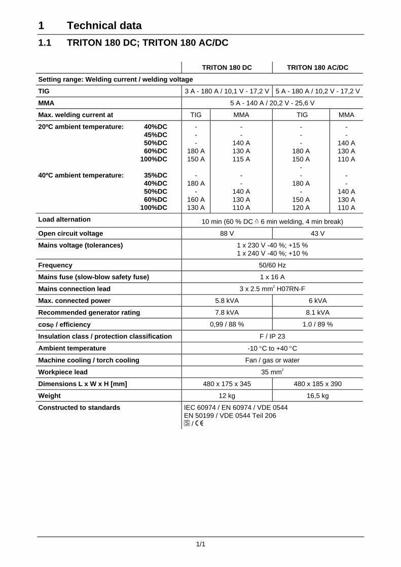
1.1 TRITON 180 DC; TRITON 180 AC/DC
TRITON 180 DC TRITON 180 AC/DC
Setting range: Welding current / welding voltage
TIG 3 A - 180 A / 10,1 V - 17,2 V 5 A - 180 A / 10,2 V - 17,2 V
MMA 5 A - 140 A / 20,2 V - 25,6 V
Max. welding current at TIG MMA TIG MMA
20ºC ambient temperature: 40%DC 45%DC 50%DC 60%DC 100%DC 40ºC ambient temperature: 35%DC 40%DC 50%DC 60%DC 100%DC
- - -
180 A150 A
-
180 A-
160 A130 A
- -
140 A 130 A 115 A
- -
140 A 130 A 110 A
- - -
180 A 150 A
- -
180 A -
150 A 120 A
- -
140 A 130 A 110 A
- -
140 A 130 A 110 A
Load alternation 10 min (60 % DC ∧ 6 min welding, 4 min break)
Open circuit voltage 88 V 43 V
Mains voltage (tolerances) 1 x 230 V -40 %; +15 % 1 x 240 V -40 %; +10 %
Frequency 50/60 Hz
Mains fuse (slow-blow safety fuse) 1 x 16 A
Mains connection lead 3 x 2.5 mm2 H07RN-F
Max. connected power 5.8 kVA 6 kVA
Recommended generator rating 7.8 kVA 8.1 kVA
cosϕ / efficiency 0,99 / 88 % 1.0 / 89 %
Insulation class / protection classification F / IP 23
Ambient temperature -10 °C to +40 °C
Machine cooling / torch cooling Fan / gas or water
Workpiece lead 35 mm2
Dimensions L x W x H [mm] 480 x 175 x 345 480 x 185 x 390
Weight 12 kg 16,5 kg
Constructed to standards IEC 60974 / EN 60974 / VDE 0544 EN 50199 / VDE 0544 Teil 206
/

1 Technical data
1/2
1.2 TRITON 220 DC; TRITON 220 AC/DC
TRITON 220 DC TRITON 220 AC/DC
Setting range: Welding current / welding voltage
TIG 3 A - 180 A / 10,1 V - 17,2 V 5 A - 180 A / 10,2 V - 17,2 V
MMA 5 A - 140 A / 20,2 V - 25,6 V
Max. welding current at TIG MMA TIG MMA
20ºC ambient temperature: 40%DC 45%DC 50%DC 60%DC 100%DC 40ºC ambient temperature: 35%DC 40%DC 50%DC 60%DC 100%DC
220 A - -
180 A 150 A
220 A
- -
160 A 130 A
- 180 A
- 160 A 140 A
180 A
- -
140 A 110 A
220 A - -
180 A 150 A
220 A
- -
160 A 130 A
- 180 A
- 160 A 140 A
180 A
- -
140 A 110 A
Load alternation 10 min (60 % DC ∧ 6 min welding, 4 min break)
Open circuit voltage 90 V 45 V
Mains voltage (tolerances) 1x230V -40%; +15% 1x240V -40%; +10%
Frequency 50/60 Hz
Mains fuse (slow-blow safety fuse) 1 x 16 A
Mains connection lead 3 x 2.5 mm2 H07RN-F
Max. connected power 5.8 kVA 5.9 kVA
Recommended generator rating 7.8 kVA 8.0 kVA
cosϕ / efficiency 1.0 / 89 %
Insulation class / protection classification F / IP 23
Ambient temperature -10 °C to +40 °C
Machine cooling / torch cooling Fan / gas or water
Workpiece lead 35 mm2
Dimensions L x W x H [mm] 480 x 185 x 390
Weight 16 kg 18 kg
Constructed to standards IEC 60974 / EN 60974 / VDE 0544 EN 50199 / VDE 0544 Teil 206
/
2 Description of the machine
2/1
A1
B1
C1
D1
E1
F1
G1
O1
N1
M1
L1
K1J1
I1
H1
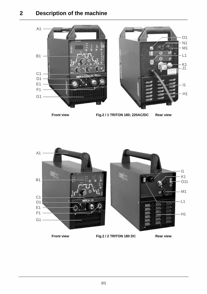
Front view Fig.2 / 1 TRITON 180; 220AC/DC Rear view
A1
B1
C1
D1
E1
F1
G1
I1
K1
O11
M1
L1
H1
Front view Fig.2 / 2 TRITON 180 DC Rear view
2 Description of the machine
2/2
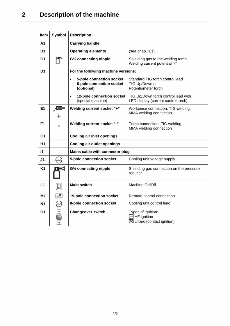
Item Symbol Description
A1 Carrying handle
B1 Operating elements (see chap. 3.1)
C1
G¼ connecting nipple Shielding gas to the welding torch Welding current potential "-"
D1 For the following machine versions:
• 5-pole connection socket Standard TIG torch control lead 8-pole connection socket TIG Up/Down or (optional) Potentiometer torch
• 12-pole connection socket TIG Up/Down torch control lead with (special machine) LED display (current control torch)
E1 +
Welding current socket "+" Workpiece connection, TIG welding, MMA welding connection
F1 - Welding current socket "-" Torch connection, TIG welding, MMA welding connection
G1 Cooling air inlet openings
H1 Cooling air outlet openings
I1 Mains cable with connector plug
J1
5-pole connection socket Cooling unit voltage supply
K1
G¼ connecting nipple Shielding gas connection on the pressure reducer
L1
Main switch Machine On/Off
M1 19-pole connection socket Remote control connection
N1 8-pole connection socket Cooling unit control lead
O1
HF
HF
Changeover switch Types of ignition: HF HF ignition HF Liftarc (contact ignition)

3 Function specification
3/1
3.1 Machine controls T2.00 and T2.05
AMP%AMP%
AMP
AMP
secsec
sec
secAMPAMP
sec
sec
sec
AMP
T2.00
PULS
AMP
VOLT
JOB
JOB
S
A1W1 B1 C1 D1
N1
O1
P1
Q1
R1
E1
I1
J1
K1
L1M1
H1 G1 Fig. 3/1: T2.00 (TRITON 180; 220 DC)
JOB 05050
7575
100100
125125150150
175175
200200HzHz1,01,0
1,61,6
2,42,4
3,23,2
4>4>
00+10+10
+20+20
+30+30 -30-30
-20-20
-10-10
%%
mmmm
AMP%AMP%
AMP
AMPAMP
secsec
sec
secsecAMPAMP
JOBsecsec
secsec
sec
AMP
T2.05
SS
PulsAC/DC
Puls
Hz%
mmmm
DC +DC +
DC -DC -
ACAC
ACAC
ACAC
AMP
VOLT
JOB
A1
S1.1
S1.2
S1.3
W1
V1
H1
I1
J1
K1
L1
M1 N1
O1
P1
Q1
R1
G1
U1 T1
F1
B1 C1 D1 E1
Fig. 3/2: T2.05 (TRITON 180; 220 AC/DC)
3 Function specification
3/2
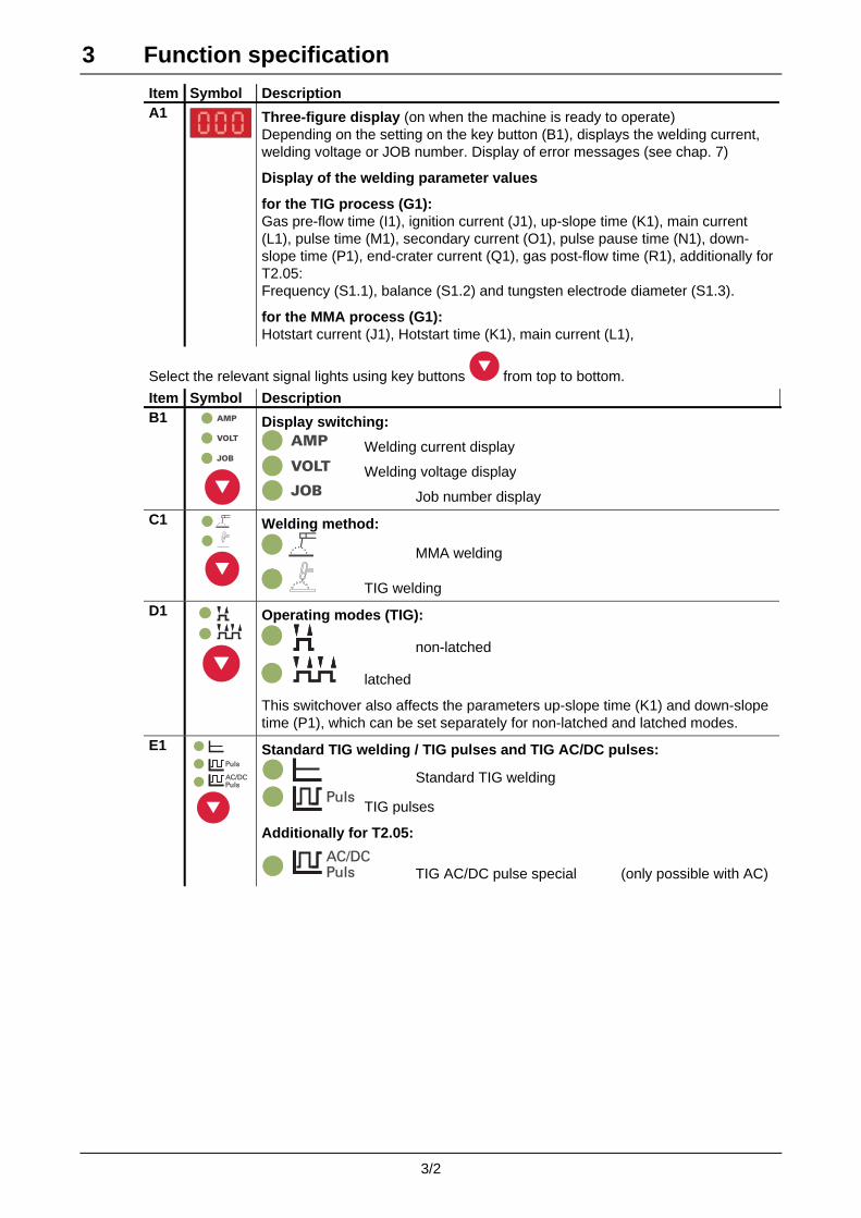
Item Symbol Description A1
Three-figure display (on when the machine is ready to operate) Depending on the setting on the key button (B1), displays the welding current, welding voltage or JOB number. Display of error messages (see chap. 7)
Display of the welding parameter values
for the TIG process (G1): Gas pre-flow time (I1), ignition current (J1), up-slope time (K1), main current (L1), pulse time (M1), secondary current (O1), pulse pause time (N1), down-slope time (P1), end-crater current (Q1), gas post-flow time (R1), additionally for T2.05: Frequency (S1.1), balance (S1.2) and tungsten electrode diameter (S1.3).
for the MMA process (G1): Hotstart current (J1), Hotstart time (K1), main current (L1),
Select the relevant signal lights using key buttons from top to bottom.
Item Symbol Description B1 AMP
VOLT
JOB
Display switching: AMP Welding current display VOLT Welding voltage display JOB Job number display
C1
Welding method:
MMA welding
TIG welding
D1
Operating modes (TIG):
non-latched
latched
This switchover also affects the parameters up-slope time (K1) and down-slope time (P1), which can be set separately for non-latched and latched modes.
E1
PulsAC/DC
Puls
Standard TIG welding / TIG pulses and TIG AC/DC pulses:
Standard TIG welding Puls
TIG pulses
Additionally for T2.05:
PulsAC/DC
TIG AC/DC pulse special (only possible with AC)
3 Function specification
3/3
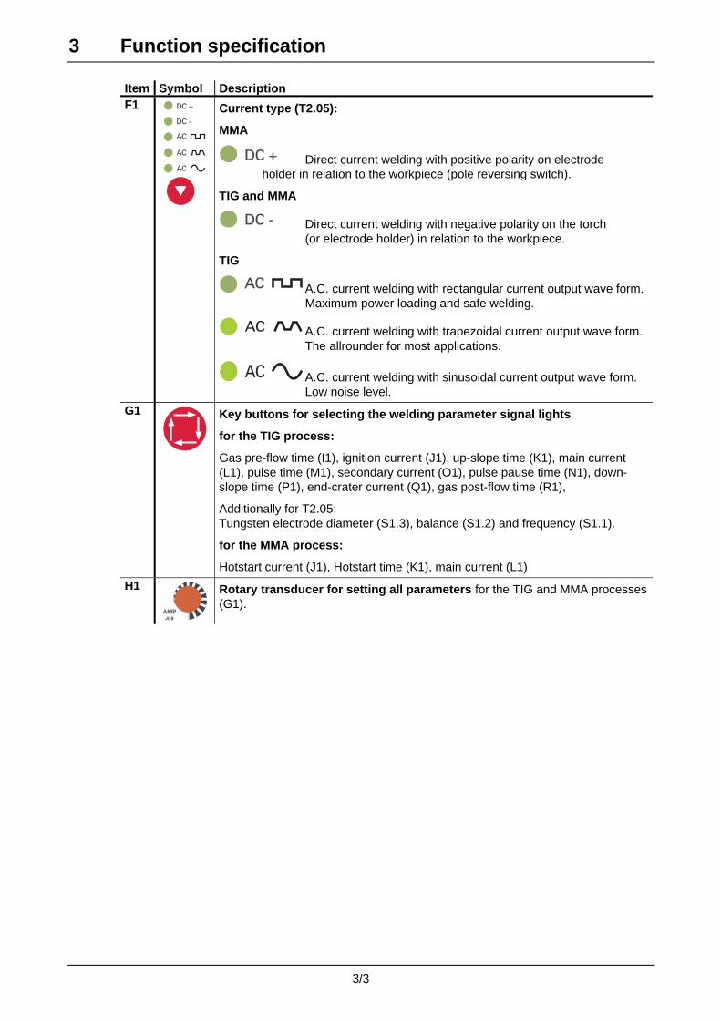
Item Symbol Description F1 DC +DC +
DC -DC -
ACAC
ACAC
ACAC
Current type (T2.05):
MMA
DC +DC + Direct current welding with positive polarity on electrode holder in relation to the workpiece (pole reversing switch).
TIG and MMA
DC -DC - Direct current welding with negative polarity on the torch (or electrode holder) in relation to the workpiece.
TIG
ACAC A.C. current welding with rectangular current output wave form. Maximum power loading and safe welding.
ACAC A.C. current welding with trapezoidal current output wave form. The allrounder for most applications.
ACAC A.C. current welding with sinusoidal current output wave form. Low noise level.
G1
Key buttons for selecting the welding parameter signal lights
for the TIG process:
Gas pre-flow time (I1), ignition current (J1), up-slope time (K1), main current (L1), pulse time (M1), secondary current (O1), pulse pause time (N1), down-slope time (P1), end-crater current (Q1), gas post-flow time (R1),
Additionally for T2.05: Tungsten electrode diameter (S1.3), balance (S1.2) and frequency (S1.1).
for the MMA process:
Hotstart current (J1), Hotstart time (K1), main current (L1)
H1
AMPAMPJOB
Rotary transducer for setting all parameters for the TIG and MMA processes (G1).
3 Function specification
3/4
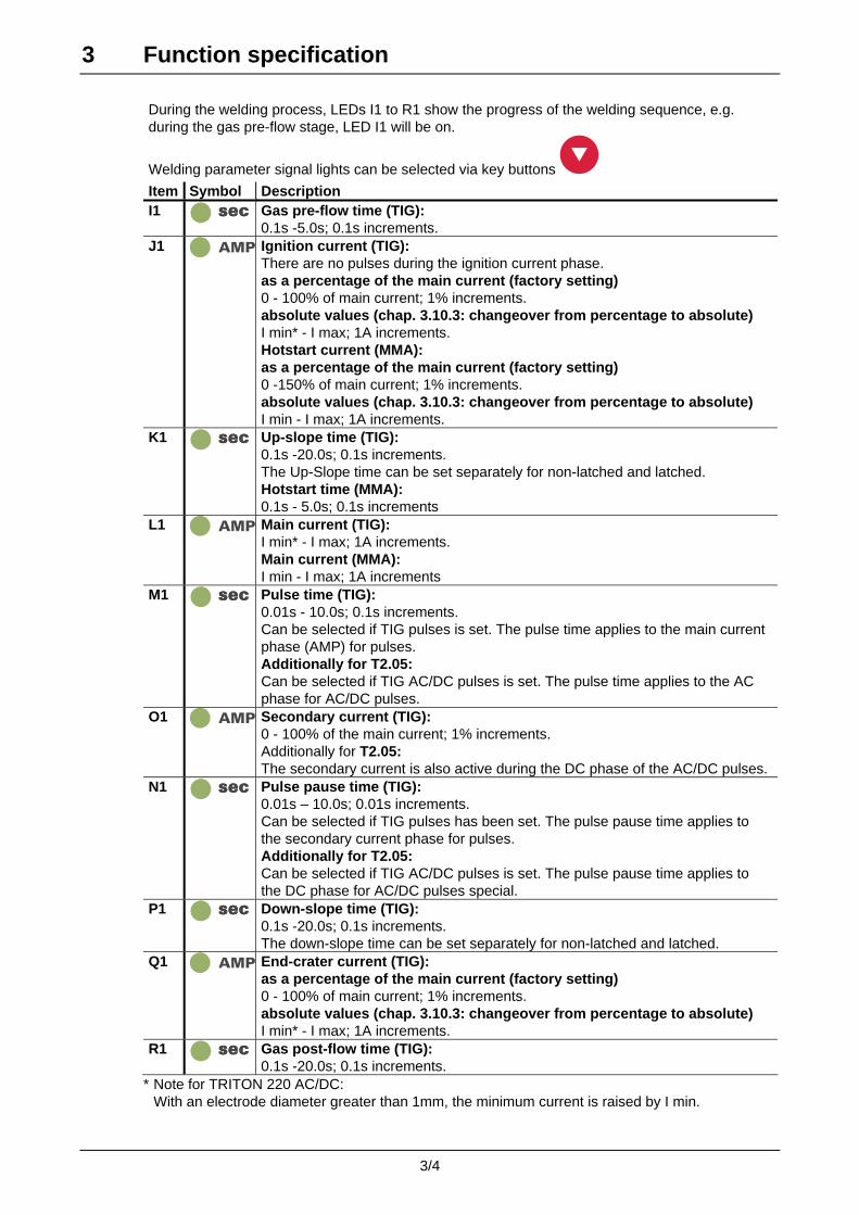
During the welding process, LEDs I1 to R1 show the progress of the welding sequence, e.g. during the gas pre-flow stage, LED I1 will be on.
Welding parameter signal lights can be selected via key buttons
Item Symbol Description I1 secsec
Gas pre-flow time (TIG): 0.1s -5.0s; 0.1s increments.
J1 AMP Ignition current (TIG): There are no pulses during the ignition current phase. as a percentage of the main current (factory setting) 0 - 100% of main current; 1% increments. absolute values (chap. 3.10.3: changeover from percentage to absolute) I min* - I max; 1A increments. Hotstart current (MMA): as a percentage of the main current (factory setting) 0 -150% of main current; 1% increments. absolute values (chap. 3.10.3: changeover from percentage to absolute) I min - I max; 1A increments.
K1 secsec Up-slope time (TIG): 0.1s -20.0s; 0.1s increments. The Up-Slope time can be set separately for non-latched and latched. Hotstart time (MMA): 0.1s - 5.0s; 0.1s increments
L1 AMP Main current (TIG): I min* - I max; 1A increments. Main current (MMA): I min - I max; 1A increments
M1 secsec Pulse time (TIG): 0.01s - 10.0s; 0.1s increments. Can be selected if TIG pulses is set. The pulse time applies to the main current phase (AMP) for pulses. Additionally for T2.05: Can be selected if TIG AC/DC pulses is set. The pulse time applies to the AC phase for AC/DC pulses.
O1 AMP Secondary current (TIG): 0 - 100% of the main current; 1% increments. Additionally for T2.05: The secondary current is also active during the DC phase of the AC/DC pulses.
N1 secsec Pulse pause time (TIG): 0.01s – 10.0s; 0.01s increments. Can be selected if TIG pulses has been set. The pulse pause time applies to the secondary current phase for pulses. Additionally for T2.05: Can be selected if TIG AC/DC pulses is set. The pulse pause time applies to the DC phase for AC/DC pulses special.
P1 secsec Down-slope time (TIG): 0.1s -20.0s; 0.1s increments. The down-slope time can be set separately for non-latched and latched.
Q1 AMP End-crater current (TIG): as a percentage of the main current (factory setting) 0 - 100% of main current; 1% increments. absolute values (chap. 3.10.3: changeover from percentage to absolute) I min* - I max; 1A increments.
R1 secsec Gas post-flow time (TIG): 0.1s -20.0s; 0.1s increments.
* Note for TRITON 220 AC/DC: With an electrode diameter greater than 1mm, the minimum current is raised by I min.

3 Function specification
3/5
T2.05 only:
Items S1.1, S1.2 and S1.3 are active in all JOBs (except in JOB 0) (See chap. 3.2). The rotary dials T1, U1 and V1 are deactivated (JOB 1 - 7).
Item Symbol Description
AC frequency (AC): S1.1 Hz 50Hz - 200Hz; 1Hz increments. Constriction and stabilisation of the arc. At a higher frequency, the cleaning effect is increased. Particularly thin panels (welding with a low current), anodised sheet aluminium or highly contaminated articles for welding can be welded and cleaned perfectly at a higher frequency.
AC balance (AC): S1.2 %
-30% - +30%;1% increments. Optimisation of cleaning effect and fusion penetration characteristics. An increase in the positive half-wave means: - greater cleaning effect - higher temperature of the tungsten
electrode - greater ball formation on the tungsten
electrode - broader weld seam, little fusion penetration An increase in the negative half-wave means: - narrower weld seam, deeper fusion
penetration - smaller cleaning effect - lower temperature of the tungsten electrode- smaller ball formation on the tungsten
electrode
Tungsten electrode diameter (TIG): S1.3 mmmm
1.0mm -4.0mm; 0.1mm increments. The best ignition and stabilisation of the arc as well as (DC, AC) optimum ball formation in the tungsten electrode depend on the electrode diameter being used (AC). With an electrode diameter greater than 1.6 mm, the minimum current is raised by I min (DC, AC).
mmmm
3 Function specification
3/6
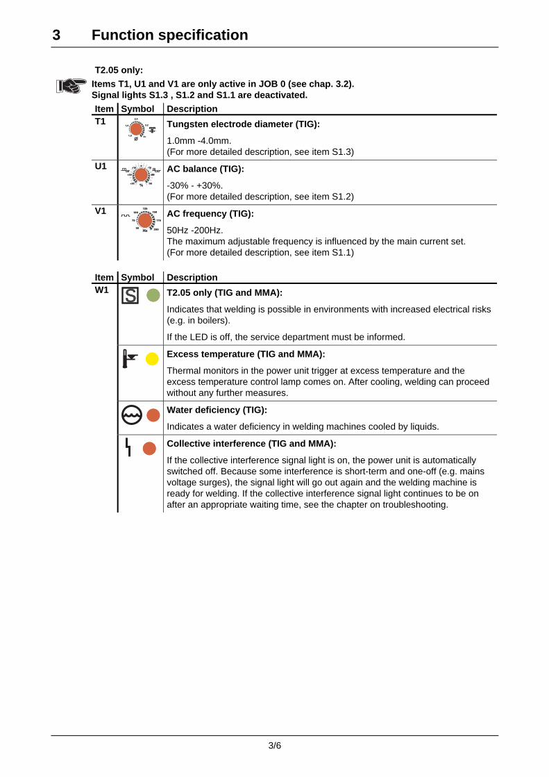
T2.05 only:
Items T1, U1 and V1 are only active in JOB 0 (see chap. 3.2). Signal lights S1.3 , S1.2 and S1.1 are deactivated.
Item Symbol Description T1
1,01,0
1,61,6
2,42,4
3,23,2
4>4>
mmmm
Tungsten electrode diameter (TIG):
1.0mm -4.0mm. (For more detailed description, see item S1.3)
U1 00+10+10
+20+20
+30+30 -30-30
-20-20
-10-10
%%
AC balance (TIG):
-30% - +30%. (For more detailed description, see item S1.2)
V1
5050
7575
100100
125125150150
175175
200200HzHz
AC frequency (TIG):
50Hz -200Hz. The maximum adjustable frequency is influenced by the main current set. (For more detailed description, see item S1.1)
Item Symbol Description W1 SS
T2.05 only (TIG and MMA):
Indicates that welding is possible in environments with increased electrical risks (e.g. in boilers).
If the LED is off, the service department must be informed.
Excess temperature (TIG and MMA):
Thermal monitors in the power unit trigger at excess temperature and the excess temperature control lamp comes on. After cooling, welding can proceed without any further measures.
Water deficiency (TIG):
Indicates a water deficiency in welding machines cooled by liquids.
Collective interference (TIG and MMA):
If the collective interference signal light is on, the power unit is automatically switched off. Because some interference is short-term and one-off (e.g. mains voltage surges), the signal light will go out again and the welding machine is ready for welding. If the collective interference signal light continues to be on after an appropriate waiting time, see the chapter on troubleshooting.
3 Function specification
3/7
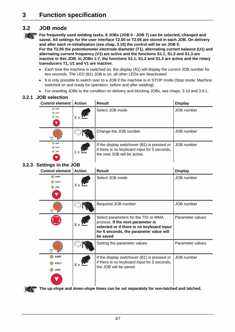
3.2 JOB mode
For frequently used welding tasks, 8 JOBs (JOB 0 - JOB 7) can be selected, changed and saved. All settings for the user interface T2.00 or T2.05 are stored in each JOB. On delivery and after each re-initialisation (see chap. 3.10) the control will be on JOB 0. For the T2.05 the potentiometer electrode diameter (T1), alternating current balance (U1) and alternating current frequency (V1) are active and the functions S1.1, S1.2 and S1.3 are inactive in this JOB. In JOBs 1-7, the functions S1.1, S1.2 and S1.3 are active and the rotary transducers T1, U1 and V1 are inactive.
• Each time the machine is switched on, the display (A1) will display the current JOB number for two seconds. The LED (B1) JOB is on, all other LEDs are deactivated.
• It is only possible to switch over to a JOB if the machine is in STOP mode (Stop mode: Machine switched on and ready for operation; before and after welding).
• For resetting JOBs to the condition on delivery and blocking JOBs, see chaps. 3.10 and 3.9.1.
3.2.1 JOB selection Control element Action Result Display
AMP
VOLT
JOB
X x
Select JOB mode JOB number
AMPAMPJOB
Change the JOB number JOB number
AMP
VOLT
JOB
1 x
If the display switchover (B1) is pressed or if there is no keyboard input for 5 seconds, the new JOB will be active.
JOB number
3.2.3 Settings in the JOB Control element Action Result Display
AMP
VOLT
JOB
X x
Select JOB mode JOB number
AMPAMPJOB
Required JOB number JOB number
X x
Select parameters for the TIG or MMA process. If the next parameter is selected or if there is no keyboard input for 5 seconds, the parameter value will be saved
Parameter values
AMPAMPJOB
Setting the parameter values Parameter values
AMP
VOLT
JOB
X x
If the display switchover (B1) is pressed or if there is no keyboard input for 5 seconds, the JOB will be saved.
JOB number
The up-slope and down-slope times can be set separately for non-latched and latched.

3 Function specification
3/8
3.3 TIG welding, general 3.3.1 Types of ignition:
HF ignition
The arc is started without contact by high-voltage ignition pulses.
Liftarc
The arc is ignited on contact with the workpiece:
a) The torch gas nozzle must be placed with its rim on the ignition point to give a gap of approx. 2-3 mm between the electrode tip and the workpiece.
b) Carefully touch the workpiece with the tungsten electrode tip. Press torch trigger in accordance with the operating mode selected.
c) The arc ignites when the torch is lifted off and swivelled to its normal position.
Fig. 3/3: Liftarc
3.3.2 Automatic shut-off
If ignition of the arc does not occur after starting or if the arc is interrupted when the torch is moved away, an automatic cut-out occurs after 3 sec. HF, gas and the open circuit voltage (power unit) are switched off.
3.3.3 Digital display The digital display (A1) indicates the following:
• Welding current
• Welding voltage
• Job number
• Error messages.
The welding current, welding voltage or job number is displayed using the key button (B1).
It also displays all adjustable values in the TIG process using the key button (G1) for selection and the rotary transducer (H1) to set the individual points in the TIG process.

3 Function specification
3/9
3.3.4 TIG welding torch, operating variants The welding process can be controlled with various torch designs (TT=torch trigger):
3.3.4.1 Standard TIG torch, 5-pole connection plug (factory setting)
The welding machine is prepared for these torch types as standard.
Symbol Description Functions Operation with Welding current On/Off TT 1
Standard TIG torch Design: 1 trigger Secondary current TT 1 in tapping mode
Welding current On/Off TT 1 Secondary current TT 2
Standard TIG torch Design: 2 triggers
Secondary current TT 1 in tapping mode
Welding current On/Off TT 1 (rocker forwards) Secondary current TT 2 (rocker back)
Standard TIG torch Design: 2 triggers (MG rocker)
Secondary current TT 1 (rocker forwards) in tapping mode
Special functions with standard TIG torches such as e.g. Up/Down operation (see Chapter 3.9.2)
3.3.4.2 TIG up/down torch, 8-pole connection plug (optional)
The welding machine is prepared for this torch type as standard.
Symbol Description Functions Operation with Welding current On/Off TT Secondary current TT in tapping mode
TIG up/down torch Design: 1 trigger + 2 triggers (rocker) Increase / reduce
welding current Rocker forwards / rocker back
The last welding current set is stored in the memory and is available after switching on again.
3.3.4.3 TIG potentiometer torch, 8-pole connection plug
For machines with 8-pole connection sockets (optional), it is not possible to differentiate between TIG up/down torches and potentiometer torches via the torch detection system
Before commissioning, the welding machine must be converted for the TIG potentiometer torch. (see chapter 3.11)
The TIG potentiometer torch can only be used in mode 3.
Symbol Description Functions Operation with Welding current On/Off TT Secondary current TT in tapping mode
TIG potentiometer torch Design: 1 trigger + 1 wheel (potentiometer) Increase / reduce
welding current Turn potentiometer backwards / forwards
3.3.5 Tapping operating mode The tapping mode was included particularly for the secondary current (AMP%) by the use of a trigger on the welding torch.
Torch with one trigger:
• by tapping (brief pressing and releasing) torch trigger 1 (Repeated tapping switches back to the main current).
Torch with two triggers:
There are two ways of switching to the secondary current:
• by tapping (see torch with one trigger)
• by pressing down and holding torch trigger 2.
3 Function specification
3/10
3.4 TIG function sequences All the parameters for the TIG process can be controlled using the key button (G1) to select the parameters and the rotary transducer (H1) for setting them:
• Main current AMP,
• Secondary current AMP%,
• Gas pre-flow time,
• Ignition current,
• Up-slope time,
• Pulse current time,
• Pause current time,
• Down-slope time,
• End-crater current,
• Gas post-flow time,
• Electrode diameter,
• Balance,
• Frequency.
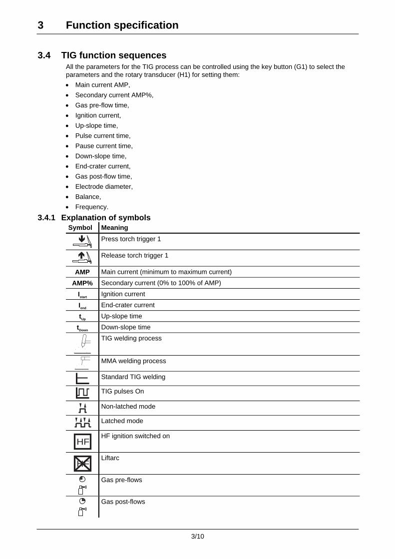
3.4.1 Explanation of symbols Symbol Meaning
Press torch trigger 1
Release torch trigger 1
AMP Main current (minimum to maximum current)
AMP% Secondary current (0% to 100% of AMP)
Istart Ignition current
Iend End-crater current
tUp Up-slope time
tDown Down-slope time
TIG welding process
MMA welding process
Standard TIG welding
TIG pulses On
Non-latched mode
Latched mode
HF
HF ignition switched on
HF
Liftarc
Gas pre-flows
Gas post-flows
3 Function specification
3/11
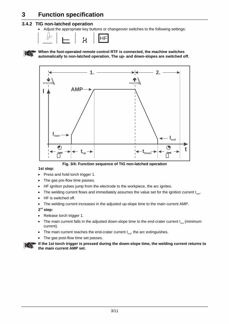
3.4.2 TIG non-latched operation • Adjust the appropriate key buttons or changeover switches to the following settings:
HF
When the foot-operated remote control RTF is connected, the machine switches automatically to non-latched operation. The up- and down-slopes are switched off.
I
Istart
AMP
tUp
1. 2.
tDown
Iend
t
Fig. 3/4: Function sequence of TIG non-latched operation
1st step:
• Press and hold torch trigger 1.
• The gas pre-flow time passes.
• HF ignition pulses jump from the electrode to the workpiece, the arc ignites.
• The welding current flows and immediately assumes the value set for the ignition current Istart.
• HF is switched off.
• The welding current increases in the adjusted up-slope time to the main current AMP.
2nd step:
• Release torch trigger 1.
• The main current falls in the adjusted down-slope time to the end-crater current Iend (minimum current).
• The main current reaches the end-crater current Iend, the arc extinguishes.
• The gas post-flow time set passes.
If the 1st torch trigger is pressed during the down-slope time, the welding current returns to the main current AMP set.

3 Function specification
3/12
3.4.3 TIG latched operation • Adjust the appropriate key buttons or changeover switches to the following settings:
HF
When the foot-operated remote control RTF is connected, the machine switches automatically to non-latched operation. The up- and down-slopes are switched off.
I
Istart
AMP
Iend
tUp tDown
t
AMP%
1. 2. 3. 4.
Fig. 3/5: TIG latched function sequence
Step 1
• Press torch trigger 1, the gas pre-flow time passes.
• HF ignition pulses jump from the electrode to the workpiece, the arc ignites.
• Welding current flows and immediately assumes the ignition current value set (search arc at minimum setting). HF is switched off.
Step 2
• Release torch trigger 1.
• The welding current increases in the set up-slope time to the main current AMP. (Secondary current AMP% see chap. 3.1)
Switching from the main current AMP to the secondary current AMP%:
• Press torch trigger 2 or • Tap torch trigger 1 (tapping mode see also chap. 3.3.5)
Step 3
• Press torch trigger 1.
• The main current falls in the set down-slope time to the end-crater current Iend (minimum current).
4th step
• Release torch trigger 1, the arc extinguishes.
• The gas post-flow time set begins.
Immediate termination of the welding procedure without down-slope and end-crater current:
• Briefly press the 1st torch trigger (3rd and 4th step). The current falls to zero and the gas post-flow time begins.
3 Function specification
3/13
3.5 TIG pulses
The machines have an integrated pulse device. The following options are available:
T2.00: • TIG DC pulses T2.05: • TIG DC pulses • TIG AC pulses • TIG AC pulses - special
The TIG DC and TIG AC pulses – with the exception of AC pulses special – can also be realised with the pulse remote controls RTP1 and RTP2.
3.5.1 TIG DC pulses (direct current pulses) AMP = pulse current
AMP% = pulse pause current tpuls = pulse time tpause = pulse pause time (see fig. 3/6)
AMP
AMP%
tpausetpuls
AMP
t
Fig. 3/6
3.5.2 TIG AC pulses (alternating current pulses) (T2.05 only)
AMP = pulse current AMP% = pulse pause current tpuls = pulse time tpause = pulse pause time (see fig. 3/7)
tpause tpuls
t
AMP
AMP
AMP%
Fig. 3/7
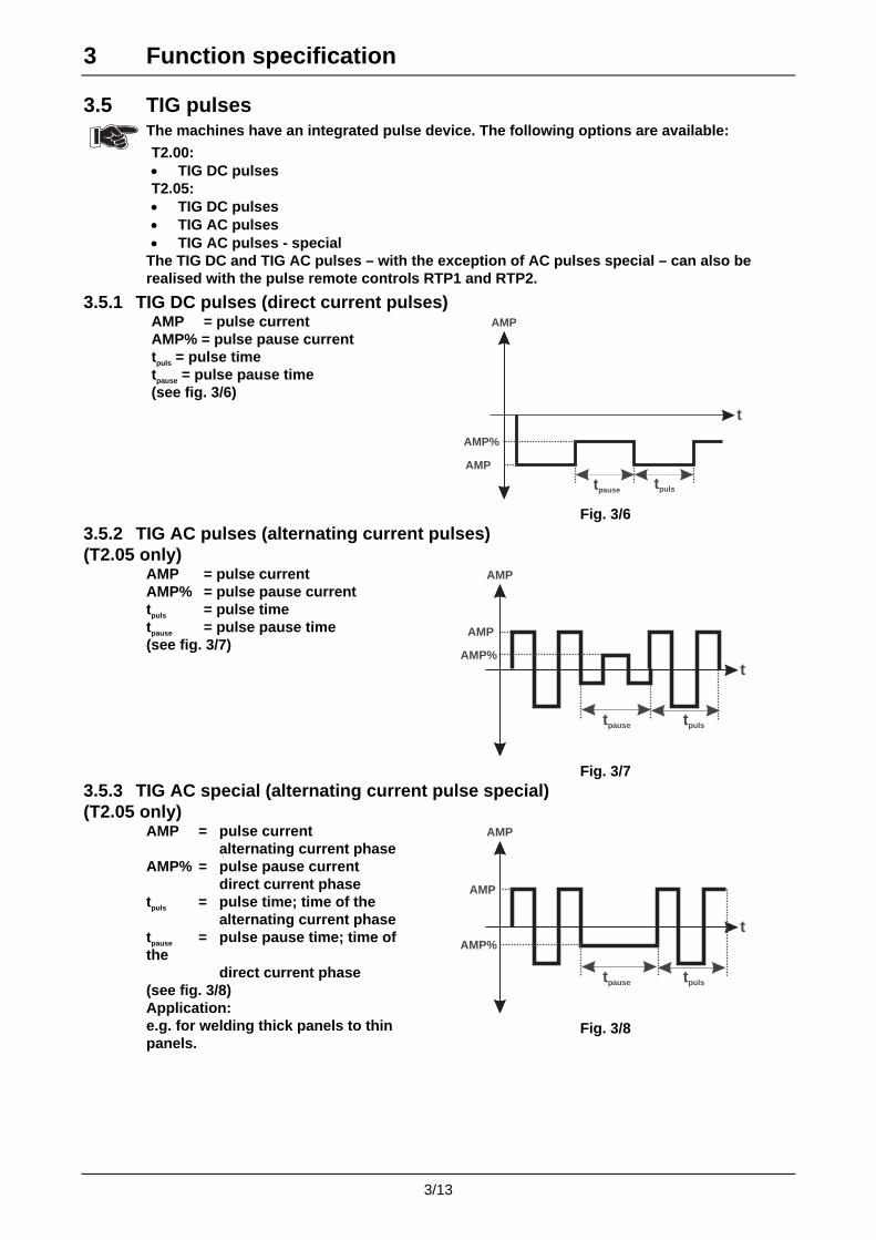
3.5.3 TIG AC special (alternating current pulse special) (T2.05 only)
AMP = pulse current alternating current phase AMP% = pulse pause current direct current phase tpuls = pulse time; time of the alternating current phase tpause = pulse pause time; time of the direct current phase (see fig. 3/8) Application: e.g. for welding thick panels to thin panels.
AMP
AMP%
tpause tpuls
AMP
t
Fig. 3/8

3 Function specification
3/14
3.5.4 TIG pulses, function sequences
The function sequences of TIG pulses are principally the same as for standard TIG welding. As soon as the arc has ignited, the current switches backwards and forwards between the pulse current and pause current at particular times.
When the foot-operated remote control RTF is connected, the machine switches automatically to non-latched operation. The up- and down-slopes are switched off.
See the explanation of symbols in chap. 3.4.1.
3.5.4.1 TIG pulses - non-latched operation
• Adjust the appropriate key buttons or changeover switches to the following settings:
HF
AMP%
I
Istart
AMP
Iend
tUp tDownt
1. 2.
Fig. 3/9: TIG pulses non-latched function sequence
Explanation as in chap. 3.4.2
3.5.4.2 TIG pulses - latched operation
• Adjust the appropriate key buttons or changeover switches to the following settings:
HF
I
Istart
AMP
Iend
tUp tDown
t
AMP%
1. 2. 3. 4.
Fig. 3/10: TIG latched function sequence
Explanation as in chap. 3.4.3

3 Function specification
3/15
3.6 MMA welding • Adjust the appropriate changeover switches to the following settings:
This machine has the following features in electrode operation:
Arcforcing
Shortly before the electrode threatens to stick, the arcforcing device sets an increased current designed to prevent the electrode sticking.
Hotstart
The hotstart device improves the ignition of the stick electrodes using an increased ignition current.
Antistick
If the stick electrode sticks despite the arcforcing device, the machine automatically switches over to the minimum current within about 1 second to prevent the electrode overheating. If the antistick device has been triggered, check the main current setting and if necessary correct it.
3 Function specification
3/16
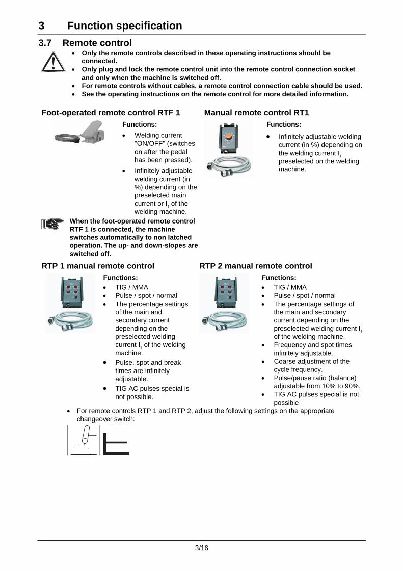
3.7 Remote control
• Only the remote controls described in these operating instructions should be connected.
• Only plug and lock the remote control unit into the remote control connection socket and only when the machine is switched off.
• For remote controls without cables, a remote control connection cable should be used.• See the operating instructions on the remote control for more detailed information.
Foot-operated remote control RTF 1 Manual remote control RT1
Functions:
• Welding current "ON/OFF" (switches on after the pedal has been pressed).
• Infinitely adjustable welding current (in %) depending on the preselected main current or I1 of the welding machine.
Functions:
• Infinitely adjustable welding current (in %) depending on the welding current I1 preselected on the welding machine.
When the foot-operated remote control RTF 1 is connected, the machine switches automatically to non latched operation. The up- and down-slopes are switched off.
RTP 1 manual remote control RTP 2 manual remote control
Functions: • TIG / MMA • Pulse / spot / normal • The percentage settings
of the main and secondary current depending on the preselected welding current I1 of the welding machine.
• Pulse, spot and break times are infinitely adjustable.
• TIG AC pulses special is not possible.
Functions: • TIG / MMA • Pulse / spot / normal • The percentage settings of
the main and secondary current depending on the preselected welding current I1 of the welding machine.
• Frequency and spot times infinitely adjustable.
• Coarse adjustment of the cycle frequency.
• Pulse/pause ratio (balance) adjustable from 10% to 90%.
• TIG AC pulses special is not possible
• For remote controls RTP 1 and RTP 2, adjust the following settings on the appropriate changeover switch:

3 Function specification
3/17
3.8 TIG interface for mechanised welding (remote control connection socket) The welding current sources feature a very high standard of safety. This safety standard is also retained when peripheral equipment is connected for automatic welding if this peripheral equipment fulfils the same criteria, particularly with regard to their isolation from the mains supply.
This is ensured by the use of transformers according to VDE 0551. The welding machines are equipped for automated operation as standard.
For automated applications, control inputs and a galvanically isolated relay contact are available at the remote control connection socket.
Interface for mechanised welding
19-pole connector socket:
• Pin A Output: Connection for cable screen.
• Pin B/L Output: Current relay contact (I>0) to the user (galvanically isolated) maximum load +/- 15 V / 100 mA.
• Pin F Output: Potentiometer reference voltage 10 V, max. 10 mA.
• Pin K Output: Power supply +15V, max. 75mA.
• Pin V Output: Power supply -15V, max. 25mA.
• Pin C Input: Nominal value for main current, 0-10V (0V = Imin, 10V = Imax)
• Pin D Input: Nominal value for secondary current, 0-10V (0V = Imin, 10V = Imax).
• Pin J/U Output: 0V
• Pin R Input: Start / stop.
• Pin H Input: Switching between main and secondary current.
• Pin S Input: Switching between MMA and TIG operation.
• Pin M/N/P Input: Nominal value identification.
• Pin G Output: Inominal 0-10V Schirm für KabelSchirm für Kabel
10V/max.10mA
A
B
L
F
C
D
E
T
S
V
K
U
J
R
H
M
N
P
G
I > 0I > 0
frei
frei
0V
+15V/75mA
-15V/25mA
Start/Stop
Wig/Elek.
Pulser I /IPulser I /IH L
FR-Typ1
FR-Typ2
FR-Typ3
ISOLL
Kennung SollwertvorgabeKennung Sollwertvorgabe
Start Stop WigElek
Ab-
senk-
strom
IL HI
strom
Haupt-
PE
10k10k
Hauptstrom 0-10VHauptstrom 0-10V
externer Sollwertexterner Sollwert
Kennung
Sollwertvorgabe
Kennung
Sollwertvorgabe
externer Sollwertexterner Sollwert
Absenkstrom 0-10VAbsenkstrom 0-10V
= externer Sollwert
für Hauptstrom aktiv
= externer Sollwert
für Hauptstrom aktiv
= externer Sollwert
für Haupt- und
Absenkstrom aktiv
= externer Sollwert
für Haupt- und
Absenkstrom aktiv
Fig. 3/8: Interface for mechanised welding, 19-pole
3 Function specification
3/18
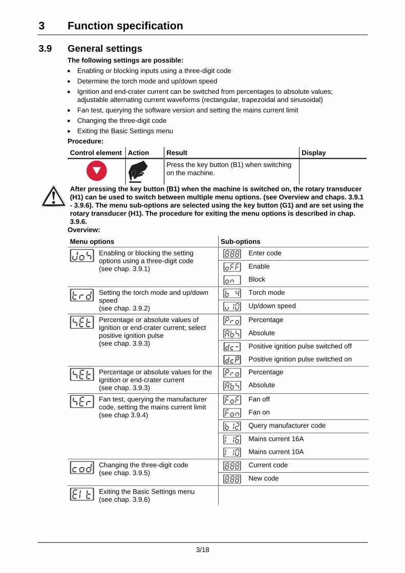
3.9 General settings The following settings are possible:
• Enabling or blocking inputs using a three-digit code
• Determine the torch mode and up/down speed
• Ignition and end-crater current can be switched from percentages to absolute values; adjustable alternating current waveforms (rectangular, trapezoidal and sinusoidal)
• Fan test, querying the software version and setting the mains current limit
• Changing the three-digit code
• Exiting the Basic Settings menu
Procedure:
Control element Action Result Display
Press the key button (B1) when switching on the machine.
After pressing the key button (B1) when the machine is switched on, the rotary transducer (H1) can be used to switch between multiple menu options. (see Overview and chaps. 3.9.1 - 3.9.6). The menu sub-options are selected using the key button (G1) and are set using the rotary transducer (H1). The procedure for exiting the menu options is described in chap. 3.9.6.
Overview:
Menu options Sub-options
Enter code
Enable
Enabling or blocking the setting options using a three-digit code (see chap. 3.9.1)
Block
Torch mode
Setting the torch mode and up/down speed (see chap. 3.9.2) Up/down speed
Percentage
Absolute
Positive ignition pulse switched off
Percentage or absolute values of ignition or end-crater current; select positive ignition pulse (see chap. 3.9.3)
Positive ignition pulse switched on
Percentage
Percentage or absolute values for the ignition or end-crater current (see chap. 3.9.3) Absolute
Fan off
Fan on
Query manufacturer code
Mains current 16A
Fan test, querying the manufacturer code, setting the mains current limit (see chap 3.9.4)
Mains current 10A
Current code
Changing the three-digit code (see chap. 3.9.5)
New code
Exiting the Basic Settings menu (see chap. 3.9.6)

3 Function specification
3/19
3.9.1 Enabling or blocking the jobs using a three-digit code
Please see chap. 3.9 for information on accessing and setting the menu options
After blocking, only the main current can be set. With the exception of the main current, all setting options described in chap. 3.1 are blocked.
Control element Action Result Display
AMPAMPJOB
Turn the rotary transducer (H1) until the display shown to the right appears.
First digit of the code. Digit will flash.
AMPAMPJOB
Set the first digit.
Second digit of the code. Digit will flash.
AMPAMPJOB
Set the second digit.
Third digit of the code. Digit will flash.
AMPAMPJOB
Set the third digit.
3s
or
AMPAMPJOB
Set Block (on) or Enable (off)
or

3 Function specification
3/20
3.9.2 Setting the torch mode and up/down speed
Please see chap. 3.9 for information on accessing and setting the menu options
Control element Action Result Display
AMPAMPJOB
Turn the rotary transducer (H1) until the display shown to the right appears.
Torch mode
AMPAMPJOB
Set torch mode
Up/down speed
AMPAMPJOB
Set up/down speed
3.9.2.1 Example for using the tables in chapters 3.9.2.2 and 3.9.2.3
Requirement:
• Up/down function with standard TIG torch (2 triggers, 5-pole connection socket)
• Select the function
• Select the relevant mode
3.9.2.2 Modes 1-4 for standard torches (5-pole connection socket; standard)
Standard torch with one torch trigger (TT)
Standard torch with two torch triggers: TT1 = left TT2 = right
Standard torch with MIG rocker
Symbol Functions Mode 1 (factory set.)
Mode 2 Mode 3 Mode 4
Welding current On/Off
TT 1 Not applicable TT 1 TT 1
Secondary
current in tapping mode
TT 1 Not applicable TT 1 TT 1
Welding current On/Off
TT1 Not applicable TT 1 TT 1
Secondary current
TT 2 Not applicable -------------------- TT 2
Secondary current in tapping
mode
TT 1 Not applicable TT 1 TT 1
Up function ------------------- Not applicable Tap + press TT 2
--------------------
Down function ------------------- Not applicable TT 2 --------------------
3 Function specification
3/21
Symbol Functions Mode 1
(factory setting)
Mode 2 Mode 3 Mode 4
Welding current On / Off
Rocker forward
Rocker in centre
Rocker forward Rocker forward
Secondary current
Rocker back -------------------- -------------------- Rocker back
Secondary current in tapping
mode
Rocker forward
Rocker in centre
Rocker forward Rocker forward
Up function ------------------- Rocker forward Tap + press rocker back
--------------------
Down function ------------------- Rocker back Rocker back --------------------
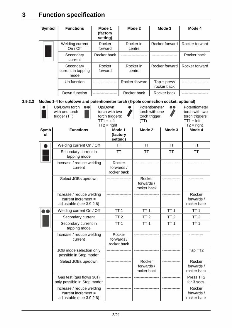
3.9.2.3 Modes 1-4 for up/down and potentiometer torch (8-pole connection socket; optional)
Up/Down torch with one torch trigger (TT)
Up/Down torch with two torch triggers:TT1 = left TT2 = right
Potentiometer torch with one torch trigger (TT)
Potentiometer torch with two torch triggers:TT1 = left TT2 = right
Symbol
Functions Mode 1 (factory setting)
Mode 2 Mode 3 Mode 4
Welding current On / Off TT TT TT TT
Secondary current in tapping mode
TT TT TT TT
Increase / reduce welding current
Rocker forwards /
rocker back
------------------- -------------- -----------
Select JOBs up/down ------------------- Rocker forwards /
rocker back
-------------- -----------
Increase / reduce welding current increment =
adjustable (see 3.9.2.6)
------------------- ------------------- -------------- Rocker forwards /
rocker back
Welding current On / Off TT 1 TT 1 TT 1 TT 1
Secondary current TT 2 TT 2 TT 2 TT 2
Secondary current in tapping mode
TT 1 TT 1 TT 1 TT 1
Increase / reduce welding current
Rocker forwards /
rocker back
------------------- -------------- -----------
JOB mode selection only possible in Stop mode*
------------------- ------------------- -------------- Tap TT2
Select JOBs up/down ------------------- Rocker forwards /
rocker back
-------------- Rocker forwards /
rocker back
Gas test (gas flows 30s) only possible in Stop mode*
------------------- ------------------- -------------- Press TT2 for 3 secs.
Increase / reduce welding current increment =
adjustable (see 3.9.2.6)
------------------- ------------------- -------------- Rocker forwards /
rocker back
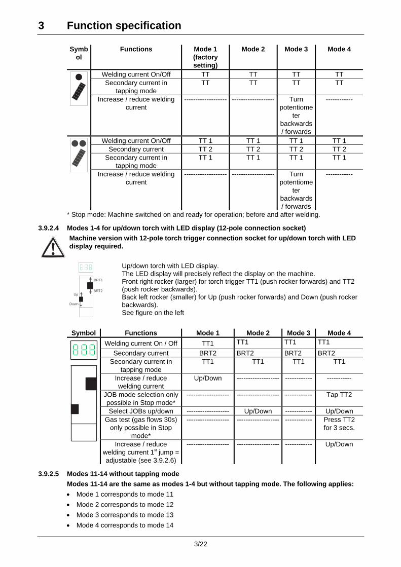
3 Function specification
3/22
Symb
ol Functions Mode 1
(factory setting)
Mode 2 Mode 3 Mode 4
Welding current On/Off TT TT TT TT Secondary current in
tapping mode TT TT TT TT
Increase / reduce welding
current ------------------- ------------------- Turn
potentiometer
backwards / forwards
------------
Welding current On/Off TT 1 TT 1 TT 1 TT 1 Secondary current TT 2 TT 2 TT 2 TT 2
Secondary current in tapping mode
TT 1 TT 1 TT 1 TT 1
Increase / reduce welding
current ------------------- ------------------- Turn
potentiometer
backwards / forwards
------------
* Stop mode: Machine switched on and ready for operation; before and after welding.
3.9.2.4 Modes 1-4 for up/down torch with LED display (12-pole connection socket)
Machine version with 12-pole torch trigger connection socket for up/down torch with LED display required.
BRT1
Down
Up
BRT2
Up/down torch with LED display. The LED display will precisely reflect the display on the machine. Front right rocker (larger) for torch trigger TT1 (push rocker forwards) and TT2 (push rocker backwards). Back left rocker (smaller) for Up (push rocker forwards) and Down (push rocker backwards). See figure on the left
Symbol Functions Mode 1 Mode 2 Mode 3 Mode 4
Welding current On / Off TT1 TT1 TT1 TT1
Secondary current BRT2 BRT2 BRT2 BRT2 Secondary current in
tapping mode TT1 TT1 TT1 TT1
Increase / reduce welding current
Up/Down ------------------- ------------ -----------
JOB mode selection only possible in Stop mode*
------------------- ------------------- ------------ Tap TT2
Select JOBs up/down ------------------- Up/Down ------------ Up/Down Gas test (gas flows 30s)
only possible in Stop mode*
------------------- ------------------- ------------ Press TT2 for 3 secs.
Increase / reduce
welding current 1st jump = adjustable (see 3.9.2.6)
------------------- ------------------- ------------ Up/Down
3.9.2.5 Modes 11-14 without tapping mode
Modes 11-14 are the same as modes 1-4 but without tapping mode. The following applies:
• Mode 1 corresponds to mode 11
• Mode 2 corresponds to mode 12
• Mode 3 corresponds to mode 13
• Mode 4 corresponds to mode 14

3 Function specification
3/23
3.9.2.6 Setting the first jump when increasing or reducing the welding current
This function is only possible with up/down torches in modes 4 and 14.
Control element Action Result Display
1 x
Press key buttons (H1) and (D1) simultaneously.
AMPAMPJOB
Set a welding current of 1-10A
1 x
Save the setting. Press key button (H1) or wait 2 secs.
Increase first jump for welding current Reduce first jump for welding current
AMP
B
t Fig. 3/9
AMPB
t Fig. 3/10
B = 1 - 10A
3 Function specification
3/24
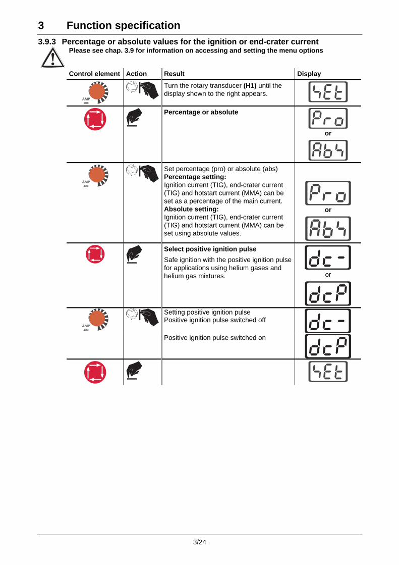
3.9.3 Percentage or absolute values for the ignition or end-crater current
Please see chap. 3.9 for information on accessing and setting the menu options
Control element Action Result Display
AMPAMPJOB
Turn the rotary transducer (H1) until the display shown to the right appears.
Percentage or absolute
or
AMPAMPJOB
Set percentage (pro) or absolute (abs) Percentage setting: Ignition current (TIG), end-crater current (TIG) and hotstart current (MMA) can be set as a percentage of the main current. Absolute setting: Ignition current (TIG), end-crater current (TIG) and hotstart current (MMA) can be set using absolute values.
or
Select positive ignition pulse
Safe ignition with the positive ignition pulse for applications using helium gases and helium gas mixtures.
or
AMPAMPJOB
Setting positive ignition pulse Positive ignition pulse switched off
Positive ignition pulse switched on

3 Function specification
3/25
3.9.4 Fan test, querying the manufacturer code and setting the mains current limit
Please see chap. 3.9 for information on accessing and setting the menu options
Control element Action Result Display
AMPAMPJOB
Turn the rotary transducer (H1) until the display shown to the right appears.
Fan test
AMPAMPJOB
Initiate fan test (phone)
Manufacturer code
Mains current limit
or
AMPAMPJOB
Set mains current limit (16A or 10A)
or
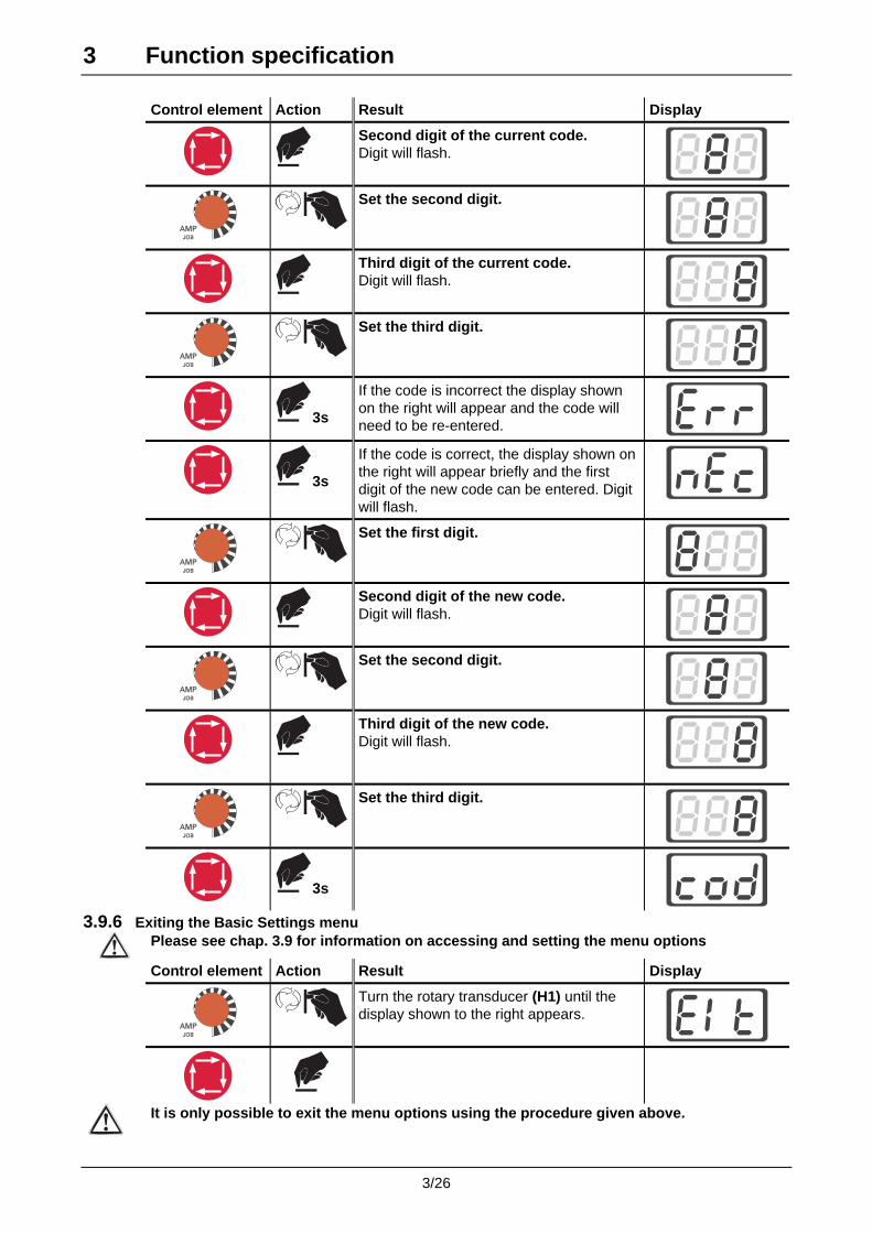
3.9.5 Changing the three-digit code
Please see chap. 3.9 for information on accessing and setting the menu options
Control element Action Result Display
AMPAMPJOB
Turn the rotary transducer (H1) until the display shown to the right appears.
First digit of the current code. Digit will flash.
AMPAMPJOB
Set the first digit.
3 Function specification
3/26
Control element Action Result Display
Second digit of the current code. Digit will flash.
AMPAMPJOB
Set the second digit.
Third digit of the current code. Digit will flash.
AMPAMPJOB
Set the third digit.
3s
If the code is incorrect the display shown on the right will appear and the code will need to be re-entered.
3s
If the code is correct, the display shown on the right will appear briefly and the first digit of the new code can be entered. Digit will flash.
AMPAMPJOB
Set the first digit.
Second digit of the new code. Digit will flash.
AMPAMPJOB
Set the second digit.
Third digit of the new code. Digit will flash.
AMPAMPJOB
Set the third digit.
3s
3.9.6 Exiting the Basic Settings menu
Please see chap. 3.9 for information on accessing and setting the menu options
Control element Action Result Display
AMPAMPJOB
Turn the rotary transducer (H1) until the display shown to the right appears.
It is only possible to exit the menu options using the procedure given above.

3 Function specification
3/27
3.10 Resetting to the delivery condition
All customised information set and saved will be lost. In addition to the values set (see chap. 3.1) all further settings such as the torch modes, up/down speed, etc. will be reset to the condition on delivery. Control element Action Result Display
Simultaneously press the trigger buttons (G1) and (B1) when switching on the machine.
The following values are factory set:
Setting Works setting Setting options blocked or enabled
Enabled
Torch mode 1 Up/down speed 0,3s/0,1s Percentage or absolute values Percentage Mains current limit setting 16A Code setting 000 Positive ignition pulse Switched off (DC-)
3 Function specification
3/28
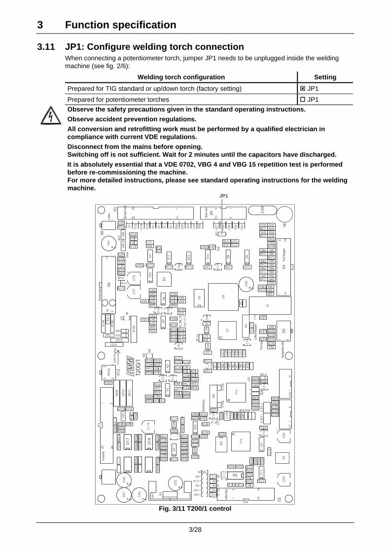
3.11 JP1: Configure welding torch connection When connecting a potentiometer torch, jumper JP1 needs to be unplugged inside the welding machine (see fig. 2/6):
Welding torch configuration Setting
Prepared for TIG standard or up/down torch (factory setting) JP1
Prepared for potentiometer torches JP1
Observe the safety precautions given in the standard operating instructions.
Observe accident prevention regulations.
All conversion and retrofitting work must be performed by a qualified electrician in compliance with current VDE regulations.
Disconnect from the mains before opening. Switching off is not sufficient. Wait for 2 minutes until the capacitors have discharged.
It is absolutely essential that a VDE 0702, VBG 4 and VBG 15 repetition test is performed before re-commissioning the machine. For more detailed instructions, please see standard operating instructions for the welding machine.
Wa
sse
rkühle
r
Bre
nne
r
Fern
reg
ler
Perip
he
rie
Tem
p
Inve
rte
r
Be
die
nte
il
WR/H
SQ
ADCSOC
XF
02
Lötric
htu
ng
: Pum
pe
Lüfte
rWa
sse
rI>
0
Test
Sta
rt/S
top
Lüfte
r
Ga
s
Uis
t
Iist
0V
-15V
+3,3V
+5V
+15V
+24V
T20
0/1
+ C1
79
+ C1
58
+ C1
57
+ C1
56
+ C1
43
+ C1
41
+ C1
32
+ C1
29
+ C1
20
+C1
17
+C
11
0
+ C9
8
+C
61
+C
16
+
C1
19
+
C7
7
+
C7
6
+
C5
5
+
C5
4
R2
11
R2
10
R2
09
R1
82
X8
1
X1
2
243
1
26
25
X3
2
1
26
25
X1
21
C63 C83
R325
V1
08
V103
V14
R321
R3
16
R3
15
R3
14
R2
28
R217
R3
13
S1N
3
D1
8
D1
7
D6
D1
D1
6
D1
4
M0
C62
1X
79
1X
10
9
+C6
0
R304
N8
Q2 R299
JP51
R297
R295
R293
R235
JP41
R291
R289
R287
R2
38
R193
V152
R191
R190
V147
V1
46
R274
R273
R270
C148
R268
V145
V144
R2
66
R1
17
R1
16
16
15X2
21
V6
1V1
1
D1
5
C114
R114
C58
D2
3
V100
N4
V5
7
V5
6
V5
5
V4
0
V3
9
V2
8
V2
7
V2
6
V2
5
V2
4
V1
3
V1
0
V7
V4
V3
V2
V1
D2
2
PE
KK1
V20
V17
R198
R196
R128
C182
LED6
R125
Q3
LED1
LED2
LED3
LED4
LED5
LED8
LED9
LED10
LED11
LED12
LED13
D2
D4
D5
D7
D8
D9
D1
0
D1
1
D1
2
D1
3D
21
N1
N2
N5
N6
N7
V8
9
V1
07
C1
08
R1
R2
R4
R5
R6
R7
R8
R9
R1
0
R1
1
R1
2
R1
3
R26
R28
R30
R32
R34
R36
R38
R39
R40
R42
R43
R44
R46
R47
R49
R66
R69
R70
R71
R72
R73
R74
R75R76
R77
R78R79
R80
R81R82
R83
R84R85
R86
R87R88
R89
R90R91
R92
R93R94
R104
R105
R107
R119
R120
R121
R122
R123
R124
R1
26
R127
R129
R139
R140
R141
R142
R143
R144
R145
R146
R147
R154R155
R157
R160
R162
R165
R170
R171
R175 R176
R186
R1
94
R2
00
R201
R204 R207
R208
R215
R216
R222
R223
R226
R227
R229
R230
R232
R233
R234R236
R237
R240
R241
R242
R243
R246
R247
R249
R250
R252
R253
R258
R260
R261
R262
R264 R265
R276
R278
R279
R280
R281
R2
82
R2
83
R2
84
R2
86
R2
88
R2
90
R2
92
R2
94
R2
96
R2
98
R3
00
R3
01
R3
03
R3
06
R3
09
V5
V8
V9
V12
V15
V18
V21V23
V43
V4
5V4
9V5
0
V63
V64
V67V74
V75
V77
V78
V83
V86
V105
V137V139
C4
C7
C11
C1
7
C1
9
C2
1
C2
3
C2
5
C2
7
C2
9
C36 C37
C38
C39
C40
C41
C42
C43
C44
C46 C47C49
C64
C67
C70
C73
C86
C89
C97
C99
C100
C102
C1
11
C1
31
C140
C142
C144C145
C146
C147
C168
C177
JP3
51
JP2
51
4
X5
1
M7
M6
Q1
C1
06
C1
05
R152
R151
R1
50
R1
49
C5
9
X6
18
10
91
RX
3
+C5
7
+C5
6
+C5
3
+C5
2
+C5
1
K1
C48
C45
10
9
X9
21
JP1 1
X4
18
10
91
C2
C1
D3
JP1
Fig. 3/11 T200/1 control
4 Quick start – the fastest way to weld
4/1
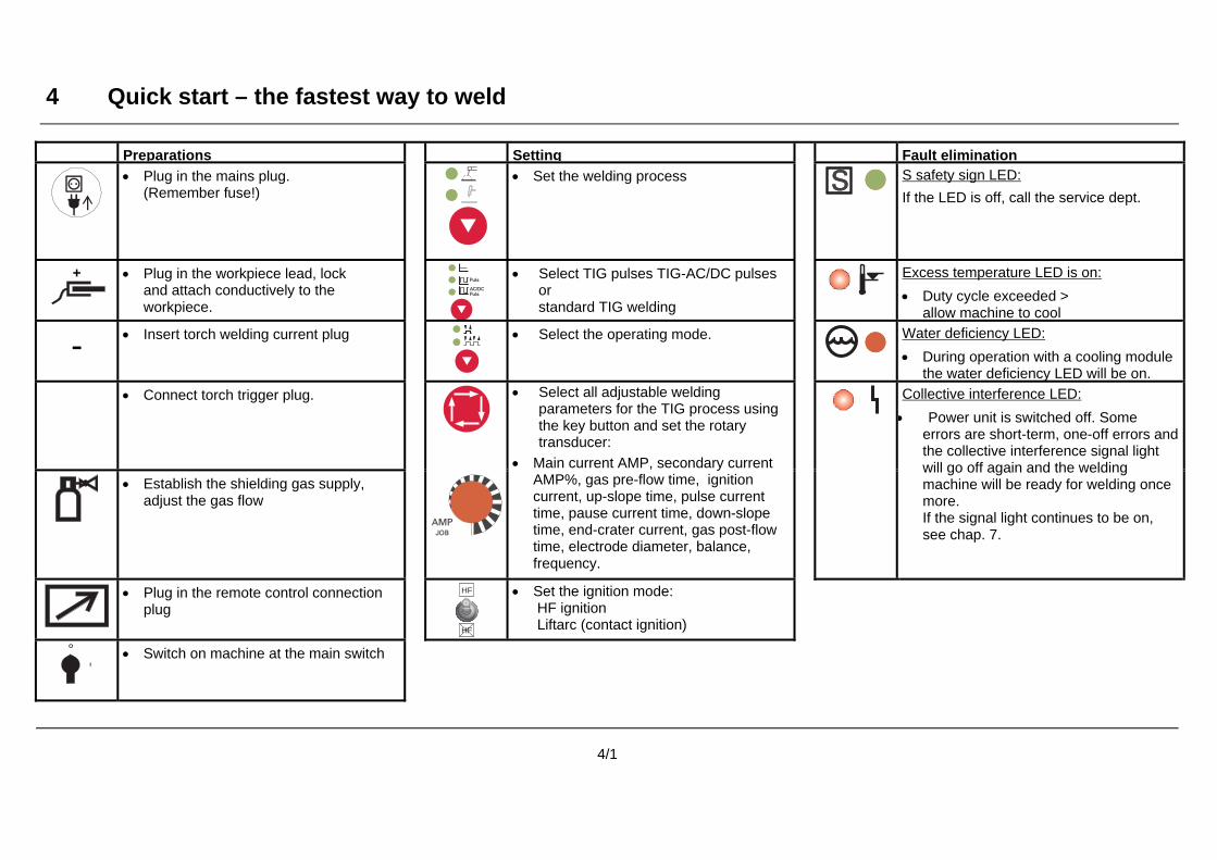
Preparations Setting Fault elimination
• Plug in the mains plug. (Remember fuse!)
• Set the welding process SS S safety sign LED:
If the LED is off, call the service dept.
+
• Plug in the workpiece lead, lock and attach conductively to the workpiece.
PulsAC/DC
Puls• Select TIG pulses TIG-AC/DC pulses
or standard TIG welding
Excess temperature LED is on:
• Duty cycle exceeded > allow machine to cool
- • Insert torch welding current plug
• Select the operating mode.
Water deficiency LED:
• During operation with a cooling module the water deficiency LED will be on.
• Connect torch trigger plug.
• Establish the shielding gas supply, adjust the gas flow
AMPAMPJOB
• Select all adjustable welding parameters for the TIG process using the key button and set the rotary transducer:
• Main current AMP, secondary current AMP%, gas pre-flow time, ignition current, up-slope time, pulse current time, pause current time, down-slope time, end-crater current, gas post-flow time, electrode diameter, balance, frequency.
Collective interference LED:
• Power unit is switched off. Some errors are short-term, one-off errors and the collective interference signal light will go off again and the welding machine will be ready for welding once more. If the signal light continues to be on, see chap. 7.
• Plug in the remote control connection plug
HF
HF • Set the ignition mode: HF ignition Liftarc (contact ignition)
• Switch on machine at the main switch

5 Commissioning
5/1
5.1 Area of application
5.1.1 Proper usage These welding machines are suitable exclusively for TIG and MMA welding. Any other use is regarded as "improper" and no liability is assumed for any damage arising therefrom.
We can only guarantee smooth and trouble-free operation of the machines when used in conjunction with the welding torches and accessories from our range.
• MMA directff current welding for rutile and basic coated electrodes.
• TIG DC and AC welding with HF ignition or Liftarc TIG-DC: Unalloyed, low-alloy and high-alloy steels, copper, nickel-based alloys and special metals. TIG AC/DC: Aluminium and aluminium alloys
5.2 Setting up the welding machine
Follow the safety instructions on the opening pages entitled "For your safety".
Set up the machine so that there is sufficient space to adjust the operating elements.
Ensure that the machine is set up in a stable position and is appropriately secured.
5.3 Mains connection
The operating voltage shown on the rating plate must match the mains voltage!
For mains fuse protection, please refer to the technical data (chapter 1).
• Insert mains plug into the appropriate socket when the machine is switched off.
5.4 Welding machine cooling system In order to achieve the optimum duty cycle for the power units, please observe the following conditions:
• Ensure that the working area is adequately ventilated,
• Do not obstruct the air inlets and outlets of the machine,
• No metal parts, dust or other foreign bodies are permitted to enter the machine.
5.5 Workpiece lead, general
Remove paint, rust and dirt from clamping and welding areas with a wire brush. The workpiece clamp must be mounted near the welding point and must be fixed in such a way that it cannot come loose of its own accord.
Structural parts, pipes, rails etc. may not be used as return leads for the welding current unless they are the workpiece themselves. A perfect current connection must be ensured for welding benches and appliances.

5 Commissioning
5/2
A1
B1
C1
D1
J1
I1
H1
G1
F1E1
Fig. 5 / 1 TRITON 180; 220 AC/DC connections
A1
B1
C1
D1
G1
F1
J1
H1
Fig. 5 / 1 TRITON 180 DC connections

5 Commissioning
5/3
5.6 MMA welding
If welding is carried out alternately using TIG and MMA welding and if a welding torch and an electrode holder are connected to the machine, the open-circuit/welding voltage is applied simultaneously to both.
The torch and the electrode holder should therefore always be placed on an insulated surface before starting work and during breaks.
When replacing spent or new stick electrodes, always switch off the machine at the main switch.
Always use insulated tongs to remove used stick electrodes or to move welded workpieces. Always put the electrode holder down on an insulated surface.
5.6.1 Electrode holder • Insert cable plug of the electrode holder into the welding current socket (C1 "+" or D1 "-") and
lock by turning to the right.
The polarity depends on the instructions from the electrode manufacturer given on the electrode packaging.
Clamp stick electrode into electrode holder. Caution: Risk of injury from crushing! Always put down stick electrode holder on an insulated surface.
5.6.2 Workpiece lead • Insert cable plug of the workpiece lead into the welding current socket (C1 "+" or D1 "-") and
lock by turning to the right.
The polarity depends on the instructions from the electrode manufacturer given on the electrode packaging.
5.7 TIG welding
If welding is carried out alternately using TIG and MMA welding and if a welding torch and an electrode holder are connected to the machine, the open-circuit/welding voltage is applied simultaneously to both.
The torch and the electrode holder should therefore always be placed on an insulated surface before starting work and during breaks.
We can only guarantee the perfect functioning of our machines when used with our range of welding torches.
TIG welding torches with shielded torch trigger control leads should not be connected (see torch operation instructions).
Follow the safety instructions on the opening pages entitled "For your safety". Before welding with a cooling module ensure that all coolant hoses are connected.
5.7.1 Welding torch, general
Always put down welding torch on an insulated surface. Prepare welding torch according to the welding task in hand (see torch operating instructions).
• Fit tungsten electrode and gas nozzle onto the welding torch (observe current load, see torch operating instructions).
• Insert the welding current plug in socket "-" (D1) and lock by turning to the right.
• Insert the torch trigger plug in the socket (B1) and tighten.
• Screw shielding gas connection of the welding torch tightly on to the connection nipple G¼ (A1) (welding current potential "-").
• For water cooled torches: Engage the rapid-action closure nipple of the TIG torch in the rapid-action closure coupling for the coolant supply (blue) and return (red) lines of the cooling module.
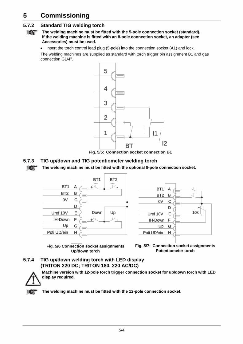
5 Commissioning
5/4
5.7.2 Standard TIG welding torch
The welding machine must be fitted with the 5-pole connection socket (standard). If the welding machine is fitted with an 8-pole connection socket, an adapter (see Accessories) must be used.
• Insert the torch control lead plug (5-pole) into the connection socket (A1) and lock.
The welding machines are supplied as standard with torch trigger pin assignment B1 and gas connection G1/4".
5
4
3
2
1
BT
I1
I2
Fig. 5/5: Connection socket connection B1
5.7.3 TIG up/down and TIG potentiometer welding torch
The welding machine must be fitted with the optional 8-pole connection socket.
A
C
E
D
G
H
F
B
Poti UD/einPoti UD/ein
IH-Down
Uref 10VUref 10V
Up
0V
BT1
BT2
UpDown
+ -
BT2
+
BT1
-
Fig. 5/6 Connection socket assignments Up/down torch
Uref 10VUref 10V
IH-Down
Poti UD/einPoti UD/ein
Up
H
G
E
F
10k
0V C
D
BT1
BT2
A
B
Fig. 5/7: Connection socket assignments
Potentiometer torch
5.7.4 TIG up/down welding torch with LED display (TRITON 220 DC; TRITON 180, 220 AC/DC) Machine version with 12-pole torch trigger connection socket for up/down torch with LED display required.
The welding machine must be fitted with the 12-pole connection socket.
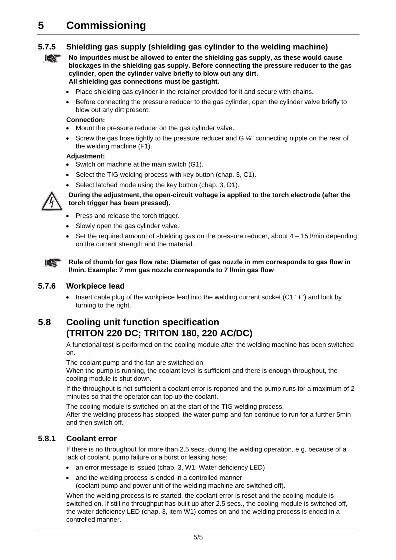
5 Commissioning
5/5
5.7.5 Shielding gas supply (shielding gas cylinder to the welding machine)
No impurities must be allowed to enter the shielding gas supply, as these would cause blockages in the shielding gas supply. Before connecting the pressure reducer to the gas cylinder, open the cylinder valve briefly to blow out any dirt. All shielding gas connections must be gastight.
• Place shielding gas cylinder in the retainer provided for it and secure with chains.
• Before connecting the pressure reducer to the gas cylinder, open the cylinder valve briefly to blow out any dirt present.
Connection: • Mount the pressure reducer on the gas cylinder valve.
• Screw the gas hose tightly to the pressure reducer and G ¼" connecting nipple on the rear of the welding machine (F1).
Adjustment: • Switch on machine at the main switch (G1).
• Select the TIG welding process with key button (chap. 3, C1). • Select latched mode using the key button (chap. 3, D1).
During the adjustment, the open-circuit voltage is applied to the torch electrode (after the torch trigger has been pressed).
• Press and release the torch trigger.
• Slowly open the gas cylinder valve.
• Set the required amount of shielding gas on the pressure reducer, about 4 – 15 l/min depending on the current strength and the material.
Rule of thumb for gas flow rate: Diameter of gas nozzle in mm corresponds to gas flow in l/min. Example: 7 mm gas nozzle corresponds to 7 l/min gas flow
5.7.6 Workpiece lead • Insert cable plug of the workpiece lead into the welding current socket (C1 "+") and lock by
turning to the right.
5.8 Cooling unit function specification (TRITON 220 DC; TRITON 180, 220 AC/DC) A functional test is performed on the cooling module after the welding machine has been switched on.
The coolant pump and the fan are switched on. When the pump is running, the coolant level is sufficient and there is enough throughput, the cooling module is shut down.
If the throughput is not sufficient a coolant error is reported and the pump runs for a maximum of 2 minutes so that the operator can top up the coolant.
The cooling module is switched on at the start of the TIG welding process. After the welding process has stopped, the water pump and fan continue to run for a further 5min and then switch off.
5.8.1 Coolant error If there is no throughput for more than 2.5 secs. during the welding operation, e.g. because of a lack of coolant, pump failure or a burst or leaking hose:
• an error message is issued (chap. 3, W1: Water deficiency LED)
• and the welding process is ended in a controlled manner (coolant pump and power unit of the welding machine are switched off).
When the welding process is re-started, the coolant error is reset and the cooling module is switched on. If still no throughput has built up after 2.5 secs., the cooling module is switched off, the water deficiency LED (chap. 3, item W1) comes on and the welding process is ended in a controlled manner.
6 Maintenance and care
6/1
6.1 General Under the indicated environmental conditions and normal operating conditions, this machine is largely maintenance-free and requires minimum care. However, a number of points should be observed to guarantee fault-free operation of your welding machine. Among these are regular cleaning and checking as described below, depending on the level of contamination in the environment and the usage time of the welding machine.
Cleaning, testing and repairing of the welding machines may only be carried out by competent, capable personnel. A capable person is one who, due to training, knowledge and experience, is able to recognise the dangers that can occur during testing of welding power sources as well as possible subsequent damage and who is able to implement the required safety procedures.
In the event of failure to comply with any one of the following tests, the machine must not be operated again until it has been repaired and a new test has been carried out.
6.2 Cleaning
Before cleaning, carefully disconnect the machine from the mains. PULL OUT THE MAINS PLUG.(Switching off or pulling out the fuse does not provide adequate insulation protection) Wait 2 minutes until the capacitors are discharged. Remove the casing cover.
The individual components should be handled as follows:
Power source: Depending on the amount of dust, blow out power source using oil- and moisture-free compressed air.
Electronics: Do not blast electronic components or circuit boards with compressed air but instead use suction from a vacuum cleaner for cleaning purposes.
6.3 Repetition Test conforming to E VDE 0544-207, conforming to the German Ordinance on Operational Safety
In addition to the regulations on the repetition test mentioned here, the relevant laws and regulations in the country of use must be observed.
The repetition test must be conducted in accordance with E VDE 0544-207 “Repetition Test on Arc Welding Equipment”. The draft standard summarises all the necessary test points specifically for welding machines as already cited together in the VDE 0702 “Repetition Test for Electrical Devices”, with the addition of special application notes and different limit values.
Unfortunately, many test devices for VDE 0702 are not completely suitable due to the special conditions in inverter arc welding machines!
Recommendation: Ask your test engineer whether he is performing the test in accordance with E VDE 0544-207, the measuring equipment conforms to VDE0404-2 and the frequency response is being evaluated in accordance with DIN EN 61010-1 Appendix A – Measuring Circuit A1. Have this confirmed in writing if necessary.
EWM as a manufacturer has specified a separate test device and provides its EWM dealers with the necessary support to conduct a repetition test to E VDE 0544-207 correctly.
If the repetition test is not conducted in accordance with the standards and / or not at the prescribed intervals, the right to claim under the warranty lapses!
The following description of the repetition test is only a brief overview of the products to be tested. For details on the test points or in the event of any queries, please read E VDE 0544-207.

6 Maintenance and care
6/2
6.3.1 Test intervals and scope A quarterly partial test and an annual extensive test are to be carried out. The extensive test must also be carried out each time that repairs are made; in the case of heavy use, the period can be reduced (e.g. to 6 months when used at construction sites). In the extensive test, the machine must be opened and cleaned according to the section entitled “Cleaning”. Only exterior cleaning is required for the partial test.
Partial test Full test
a) Visual check a) Visual check b) Electrical test: measurement of Protective
conductor resistance b) Electrical test: measurement of
• Protective conductor resistance • Insulation resistance • Leakage currents • Open circuit voltage
c) Functional test c) Functional test
6.3.2 Documentation of the test The result of the test must be documented to show the following clearly:
• • Identify the tested machines,
• • The date of the test
• • The time of the next test and
• • The results
for later reference. The machine must be marked if the test is successful (e.g. with a test plate). This plate must include the date of the next repetition test.
6.3.3 Visual inspection Given below are the main points in the full test. The points to be tested with the machine open are not required for the partial test.
• 1. Torch/stick electrode holder, welding current return lead clamp
• 2. Leads including plugs and couplings
• 3. Open plugs and couplings
• 4. Casing
• 5. Open casing
• 6. Special features of the welding power sources for plasma cutting
• 7. Operating, message, safety and adjustment devices
• 8. Other, general condition
6.3.4 Measurement of protective conductor resistance Measure between the plug earthed contact and accessible metal parts, e.g. casing screws. During the measurement, the connection lead must be moved across the entire length, but especially close to the casing and plug inputs. This should uncover any interruptions in the protective conductor. All conductive parts of the casing accessible from outside should also be tested to ensure a correct PE connection for safety class I.
The resistance must not exceed a mains connection lead 0.3 Ω up to 5m in length. For longer leads, the permissible value increases by 0.1 Ω per 7.5m of lead.

6 Maintenance and care
6/3
6.3.5 Measurement of insulation resistance The mains switch must be on before the insulation in the interior of the machine through to the transformer can be checked. If a mains contactor is fitted, this should be bridged or the measurement must be carried out on both sides.
The insulation resistance must not be less than:
Input power circuit (mains)
against Welding current circuit and electronics
5 MΩ at test voltage 1000V=
Input power circuit (mains)
against Casing (PE) 2.5 MΩ at test voltage 500V =
Welding current circuit and electronics
against Casing (PE) 2.5 MΩ at test voltage 500V =
6.3.6 Measuring the leakage current (protective conductor and contact current) These measurements cannot be carried out with a normal multimeter. Even test devices for VDE 0702 (especially older devices) are generally only intended for 50/60Hz. With inverter welding machines, however, significantly higher frequencies occur, which can interfere with some measuring devices, and results in others measuring the frequency incorrectly.
Test devices must meet the requirements of VDE 0404-2. For the frequency response measurement, please refer to DIN EN 61010-1 Appendix A – Measuring Circuit A1.
For these measurements the welding machine must be switched on and supplying open circuit voltage.
• 1. Protective conductor current: <3.5mA
• 2. Contact current from welding sockets separately to PE: <10mA
• 3. Contact current of accessible, conductive parts not connected to PE, to PE: <0.5mA
6.3.7 Measuring the open circuit voltage
6u8F10nF
0...5k
0k2
1k0 1N 4007
Measuring circuit to DIN EN 60974-1
Connect the measuring circuit to the welding current sockets. The voltmeter must display mean values and must have an internal resistance ≥ 1 MΩ. During the measurement, adjust the potentiometer from 0 kΩ to 5 kΩ. The voltage measured should not deviate from that given on the rating plate by more than +/- 5% and must not be greater than 113V (for machines with VRD: 35V).
6.3.8 Function test of the welding machine Safety devices, selector switches and command units (if fitted) and the entire machine or the entire system for arc welding, must be functioning perfectly.
• 1. Main switch
• 2. Emergency stop devices
• 3. Danger reduction devices
• 4. Gas solenoid valve
• 5. Message and control lamps
• 6. Command devices and selector switches (including remote controls)
• 7. Locks

6 Maintenance and care
6/4
6.4 Repair Work Repair and maintenance work may only be performed by qualified and authorised specialist staff; otherwise the right to claim under warranty is void. In all service matters, always consult the dealer who supplied the machine. Return deliveries of defective equipment subject to warranty may only be made through your dealer. When replacing parts, use only original spare parts. When ordering spare parts, please quote the machine type, serial number and item number of the machine, as well as the type designation and item number of the spare part.
We hereby confirm that the servicing and maintenance guidelines given above, and the repetition test described above, have been conducted correctly in accordance with E VDE 0544 207.
Date / Stamp / Signature of EWM sales partner Date / Stamp / Signature of EWM sales partner
Date of next repetition test Date of next repetition test
Date / Stamp / Signature of EWM sales partner Date / Stamp / Signature of EWM sales partner
Date of next repetition test Date of next repetition test
Date / Stamp / Signature of EWM sales partner Date / Stamp / Signature of EWM sales partner
Date of next repetition test Date of next repetition test
7 3-Year Warranty
7/1
7.1 General Validity 3 year warranty
on all new EWM machines:
• Power sources • Wire feeds • Cooling units • Trolley
1 year warranty
on remote controls and used EWM machines.
6 month warranty
on spare parts supplied separately (e.g. circuit boards, ignition units).
Replaceable parts are components that are subject to mechanical ageing (e.g. motors, gears, pumps, fans, WF rollers, wheels, solenoid valves, etc.) and are thus excluded from the warranty. This information applies regardless of statutory warranty rights and is based on our General Terms and Conditions as well as our accompanying Warranty Regulations.
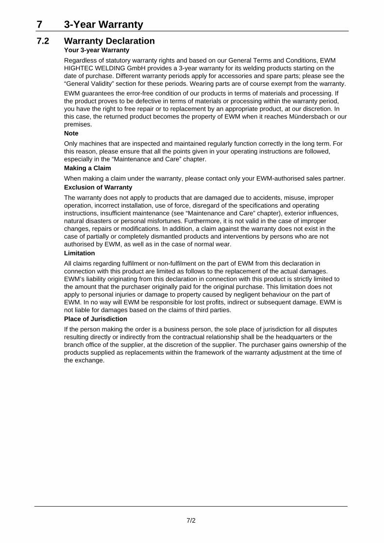
7 3-Year Warranty
7/2
7.2 Warranty Declaration Your 3-year Warranty
Regardless of statutory warranty rights and based on our General Terms and Conditions, EWM HIGHTEC WELDING GmbH provides a 3-year warranty for its welding products starting on the date of purchase. Different warranty periods apply for accessories and spare parts; please see the “General Validity” section for these periods. Wearing parts are of course exempt from the warranty.
EWM guarantees the error-free condition of our products in terms of materials and processing. If the product proves to be defective in terms of materials or processing within the warranty period, you have the right to free repair or to replacement by an appropriate product, at our discretion. In this case, the returned product becomes the property of EWM when it reaches Mündersbach or our premises. Note
Only machines that are inspected and maintained regularly function correctly in the long term. For this reason, please ensure that all the points given in your operating instructions are followed, especially in the “Maintenance and Care” chapter. Making a Claim
When making a claim under the warranty, please contact only your EWM-authorised sales partner. Exclusion of Warranty
The warranty does not apply to products that are damaged due to accidents, misuse, improper operation, incorrect installation, use of force, disregard of the specifications and operating instructions, insufficient maintenance (see “Maintenance and Care” chapter), exterior influences, natural disasters or personal misfortunes. Furthermore, it is not valid in the case of improper changes, repairs or modifications. In addition, a claim against the warranty does not exist in the case of partially or completely dismantled products and interventions by persons who are not authorised by EWM, as well as in the case of normal wear. Limitation
All claims regarding fulfilment or non-fulfilment on the part of EWM from this declaration in connection with this product are limited as follows to the replacement of the actual damages. EWM’s liability originating from this declaration in connection with this product is strictly limited to the amount that the purchaser originally paid for the original purchase. This limitation does not apply to personal injuries or damage to property caused by negligent behaviour on the part of EWM. In no way will EWM be responsible for lost profits, indirect or subsequent damage. EWM is not liable for damages based on the claims of third parties. Place of Jurisdiction
If the person making the order is a business person, the sole place of jurisdiction for all disputes resulting directly or indirectly from the contractual relationship shall be the headquarters or the branch office of the supplier, at the discretion of the supplier. The purchaser gains ownership of the products supplied as replacements within the framework of the warranty adjustment at the time of the exchange.

8 Operating problems, causes and remedies
8/1
8.1 Error messages • In the event of a machine error, an error code (see table below) is shown on the display
(chap. 3, A1).
• If multiple errors occur, these should be rectified in sequence.
Error message Possible cause Remedy
"E1" Water error Only occurs when the water cooler is connected.
Ensure that sufficient water pressure can be built up. (e.g. top up water)
"E2" Temperature error Allow machine to cool down.
"E3" Electronics error Switch the machine off and back on again. If the error persists, inform the service dept.
"E4" See "E3" See "E3"
"E5" See "E3" See "E3"
"E6" Balancing error in voltage recording. Switch off the machine, place the torch in an insulated position and switch the machine back on. If the error persists, inform the service dept.
"E7" Balancing error in current recording. Switch off the machine, place the torch in an insulated position and switch the machine back on. If the error persists, inform the service dept.
"E8" Error in one of the electronics supply voltages or excess temperature of the welding transformer.
Allow machine to cool down. If the error message persists, switch the machine off and back on again.
If the error persists, inform the service dept.
"E9" Low voltage Switch off the machine and check the mains voltage
"E10" Secondary excess voltage Switch the machine off and back on again. If the error persists, inform the service dept.
"E11" Excess voltage Switch off the machine and check the mains voltage
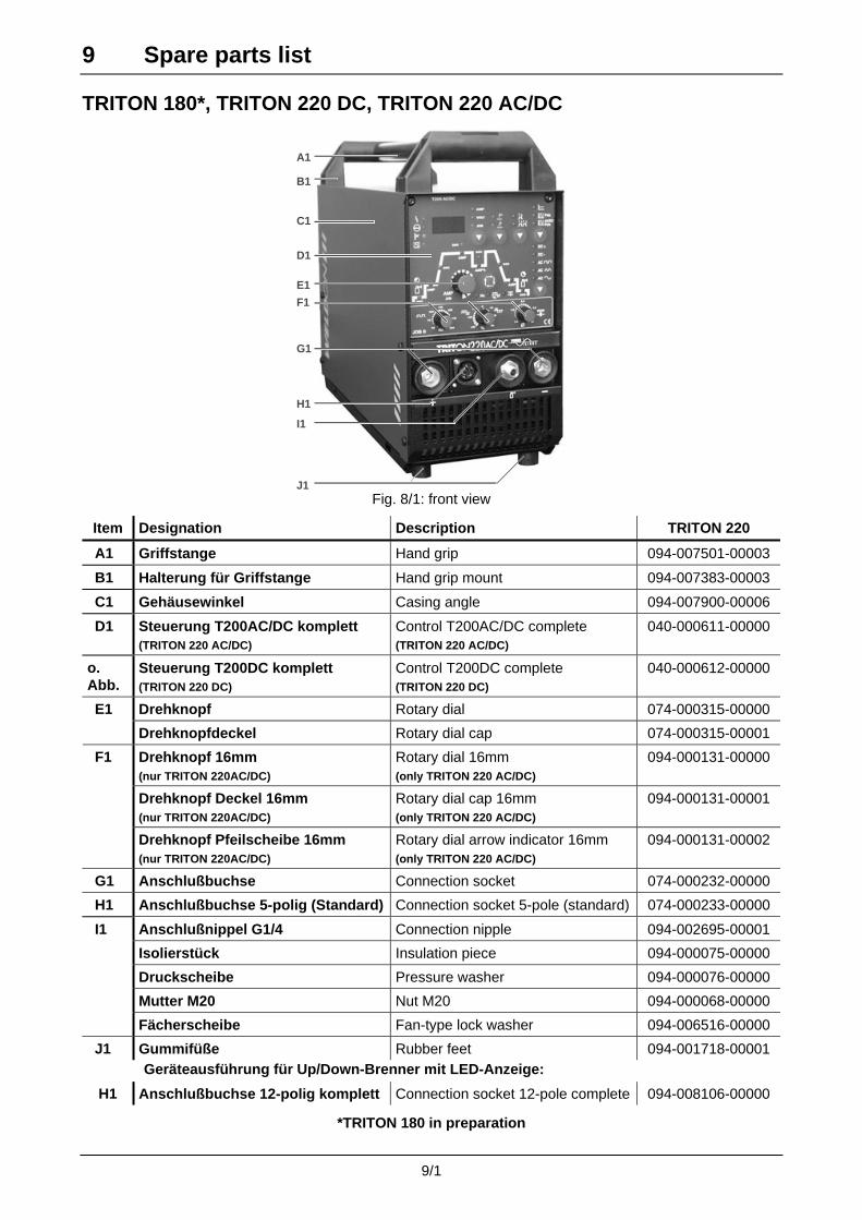
9 Spare parts list
9/1
TRITON 180*, TRITON 220 DC, TRITON 220 AC/DC
A1
B1
C1
D1
E1
F1
G1
H1
I1
J1 Fig. 8/1: front view
Item Designation Description TRITON 220
A1 Griffstange Hand grip 094-007501-00003
B1 Halterung für Griffstange Hand grip mount 094-007383-00003
C1 Gehäusewinkel Casing angle 094-007900-00006
D1 Steuerung T200AC/DC komplett (TRITON 220 AC/DC)
Control T200AC/DC complete (TRITON 220 AC/DC)
040-000611-00000
o. Abb.
Steuerung T200DC komplett (TRITON 220 DC)
Control T200DC complete (TRITON 220 DC)
040-000612-00000
Drehknopf Rotary dial 074-000315-00000 E1
Drehknopfdeckel Rotary dial cap 074-000315-00001
Drehknopf 16mm (nur TRITON 220AC/DC)
Rotary dial 16mm (only TRITON 220 AC/DC)
094-000131-00000
Drehknopf Deckel 16mm (nur TRITON 220AC/DC)
Rotary dial cap 16mm (only TRITON 220 AC/DC)
094-000131-00001
F1
Drehknopf Pfeilscheibe 16mm (nur TRITON 220AC/DC)
Rotary dial arrow indicator 16mm (only TRITON 220 AC/DC)
094-000131-00002
G1 Anschlußbuchse Connection socket 074-000232-00000
H1 Anschlußbuchse 5-polig (Standard) Connection socket 5-pole (standard) 074-000233-00000
Anschlußnippel G1/4 Connection nipple 094-002695-00001
Isolierstück Insulation piece 094-000075-00000
Druckscheibe Pressure washer 094-000076-00000
Mutter M20 Nut M20 094-000068-00000
I1
Fächerscheibe Fan-type lock washer 094-006516-00000
J1 Gummifüße Rubber feet 094-001718-00001 Geräteausführung für Up/Down-Brenner mit LED-Anzeige:
H1 Anschlußbuchse 12-polig komplett Connection socket 12-pole complete 094-008106-00000
*TRITON 180 in preparation

9 Spare parts list
9/2
A2
B2
C2
D2
E2
F2
G2
H2
Fig. 8/2 rear view
Item Designation Description TRITON 220
A2 Kippschalter Toggle switch 094-001898-00000
B2 Anschlußbuchse 8-polig Connection socket, 8-pole 094-006904-00000
C2 Anschlußbuchse 19-polig Connection socket, 19-pole 094-003064-00000
D2 Netzschalter Mains switch 094-008045-10000
Anbau Gehäuse Extension housing 094-006861-00000
Abdeckkappe Cap 094-006862-00000
E2
Buchseneinsatz Socket insert 094-007943-00000
Kabeldurchführung Screwed cable gland 094-007871-00000 F2
Gegenmutter Counter nut 094-007878-00000
G2 Magnetventil G1/4 Solenoid valve 094-005497-00001
H2 Netzkabel Mains cable 094-005142-00001
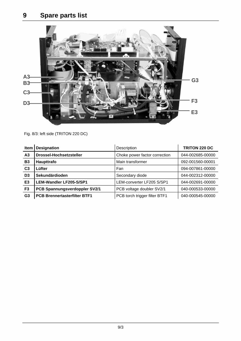
9 Spare parts list
9/3
A3G3
F3
B3
C3
D3
E3
Fig. 8/3: left side (TRITON 220 DC)
Item Designation Description TRITON 220 DC
A3 Drossel-Hochsetzsteller Choke power factor correction 044-002685-00000
B3 Haupttrafo Main transformer 092-001560-00001
C3 Lüfter Fan 094-007861-00000
D3 Sekundärdioden Secondary diode 044-002312-00000
E3 LEM-Wandler LF205-S/SP1 LEM-converter LF205 S/SP1 044-002691-00000
F3 PCB Spannungsverdoppler SV2/1 PCB voltage doubler SV2/1 040-000533-00000
G3 PCB Brennertasterfilter BTF1 PCB torch trigger filter BTF1 040-000545-00000
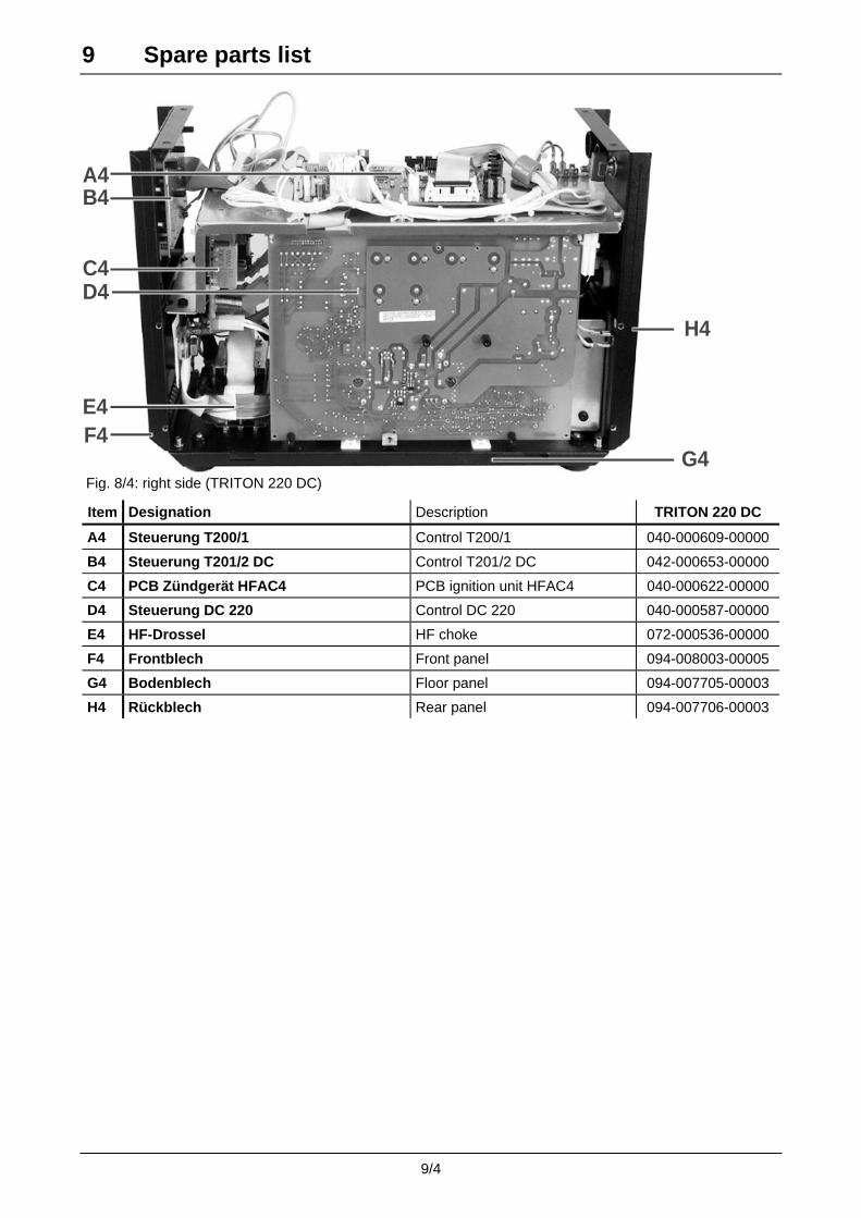
9 Spare parts list
9/4
A4
H4
G4F4
B4
C4D4
E4
Fig. 8/4: right side (TRITON 220 DC)
Item Designation Description TRITON 220 DC
A4 Steuerung T200/1 Control T200/1 040-000609-00000
B4 Steuerung T201/2 DC Control T201/2 DC 042-000653-00000
C4 PCB Zündgerät HFAC4 PCB ignition unit HFAC4 040-000622-00000
D4 Steuerung DC 220 Control DC 220 040-000587-00000
E4 HF-Drossel HF choke 072-000536-00000
F4 Frontblech Front panel 094-008003-00005
G4 Bodenblech Floor panel 094-007705-00003
H4 Rückblech Rear panel 094-007706-00003

9 Spare parts list
9/5
A5H5
G5
F5
B5
C5D5
E5
Fig. 8/5: left side (TRITON 220 AC/DC)
Item Designation Description TRITON 220 AC/DC
A5 Drossel-Hochsetzsteller Choke power factor correction 044-002685-00000
B5 Haupttrafo Main transformer 092-001560-00001
C5 Lüfter Fan 094-007861-00000
D5 Sekundärdioden (4x) BYT200 PIV400
Secondary diodes (4x) BYT200 PIV400
044-002601-00000
E5 Wechselrichter-Module (4x) GA200SA60S
Inverse rectifier moduls (4x) GA200SA60S
074-000600-00000
F5 LEM-Wandler LF205-S/SP1 LEM-converter LF205 S/SP1 044-002691-00000
G5 Wechselrichtertreiberstufe TRF5 Inverse rectifier drive stage TRF5 040-000618-00000
H5 PCB Brennertasterfilter BTF1 PCB torch trigger filter BTF1 040-000545-00000

9 Spare parts list
9/6
A6
G6
I6
J6
L6
K6
H6
F6
B6
C6
D6
E6
Fig. 8/6: right side (TRITON 220 AC/DC)
Item Designation Description TRITON 220 AC/DC
A6 PCB Schweißelektronik T200/1 PCB welding electronics 040-000609-00000
B6 PCB Tastatur T200/2 AC/DC PCB key board T200/2 AC/DC 042-000652-00000
C6 PCB Zündgerät HF AC4 PCB ignition unit HF AC4 040-000622-00000
D6 Frontblech Front panel 094-008002-00005
E6 HF Drossel HF choke 072-000536-00000
F6 Gehäuse Bodenblech Floor panel casing 094-007705-00003
G6 PCB Power Sinus DC 220 PCB Power Sinus DC 220 040-000587-00000
H6 Rückblech Rear panel 094-007706-00003 Zusätzlich für Geräteausführung mit Up/Down-Brenner (LED-Anzeige):
I6 Sättigungswandler Saturation transformer 044-000967-00000
J6 PCB Weiche WTC1 PCB WTC1 040-000625-00000
K6 Schutzbeschaltung IGRO/1 PCB protective wiring IGRO/1 040-000629-00000
L6 PCB Brennertasterfilter BTF1 PCB torch trigger filter BTF1 040-000545-00000
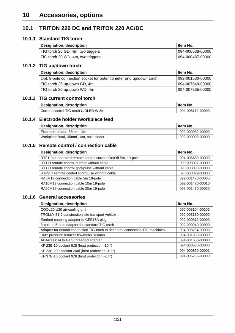
10 Accessories, options
10/1
10.1 TRITON 220 DC and TRITON 220 AC/DC
10.1.1 Standard TIG torch Designation, description Item No.
TIG torch 26 GD, 4m, two triggers 094-000538-00000TIG torch 20 WD, 4m, two triggers 094-000487-00000
10.1.2 TIG up/down torch Designation, description Item No.
Opt. 8-pole connection socket for potentiometer and up/down torch 092-001530-00000TIG torch 26 up-down GD, 4m 094-007549-00000TIG torch 20 up-down WD, 4m 094-007535-00000
10.1.3 TIG current control torch Designation, description Item No. Current control TIG torch U/DLED W 3m 094-008112-00000
10.1.4 Electrode holder /workpiece lead Designation, description Item No. Electrode holder, 35mm2, 4m 092-000052-00000 Workpiece lead, 35mm2, 4m, pole binder 092-000008-00000
10.1.5 Remote control / connection cable Designation, description Item No. RTF1 foot-operated remote control current On/Off 5m, 19-pole 094-006680-00000 RT1 H remote control current without cable 090-008097-00000 RT1 H remote control spot/pulse without cable 090-008098-00000 RTP2 H remote control spot/pulse without cable 090-008099-00000 RA5M19 connection cable 5m 19-pole 092-001470-00005 RA10M19 connection cable 10m 19-pole 092-001470-00010 RA20M19 connection cable 20m 19-pole 092-001470-00020
10.1.6 General accessories Designation, description Item No. COOL20 U20 air-cooling unit 090-008104-00102 TROLLY 31-2 construction site transport vehicle 090-008160-00000 Earthed coupling adapter to CEE16A plug 092-000812-00000 8-pole to 5-pole adapter for standard TIG torch 092-000940-00000 Adapter for central connection TIG torch to decentral connection TIG machines 094-008284-00000 DM2 pressure reducer flowmeter 16l/min 094-001980-00000 ADAP1 G1/4 to G1/8 threaded adapter 094-001650-00000
KF 23E-10 coolant 9.3l (frost protection -10 °) 094-000530-00000
KF 23E-200 coolant 200l (frost protection -10 °) 094-000530-00001
KF 37E-10 coolant 9.3l (frost protection -20 °) 094-006256-00000

10 Accessories, options
10/2
10.2 TRITON 180
10.2.1 Standard TIG torch Designation, description Item No.
TIG torch 26 GD, 4m, two triggers 094-000538-00000
10.2.2 TIG up/down torch Designation, description Item No.
Opt. 8-pole connection socket for potentiometer and up/down torch 092-001530-00000TIG torch 26 up-down GD, 4m 094-007549-00000
10.2.3 Electrode holder /workpiece lead Designation, description Item No. Electrode holder, 35mm2, 4m 092-000052-00000 Workpiece lead, 35mm2, 4m, pole binder 092-000008-00000
10.2.4 Remote control / connection cable Designation, description Item No. RTF1 foot-operated remote control current On/Off 5m, 19-pole 094-006680-00000 RT1 H remote control current without cable 090-008097-00000 RT1 H remote control spot/pulse without cable 090-008098-00000 RTP2 H remote control spot/pulse without cable 090-008099-00000 RA5M19 connection cable 5m 19-pole 092-001470-00005 RA10M19 connection cable 10m 19-pole 092-001470-00010 RA20M19 connection cable 20m 19-pole 092-001470-00020
10.2.5 General accessories Designation, description Item No. Earthed coupling adapter to CEE16A plug 092-000812-00000 8-pole to 5-pole adapter for standard TIG torch 092-000940-00000 Adapter for central connection TIG torch to decentral connection TIG machines 094-008284-00000 DM2 pressure reducer flowmeter 16l/min 094-001980-00000 ADAP1 G1/4 to G1/8 threaded adapter 094-001650-00000
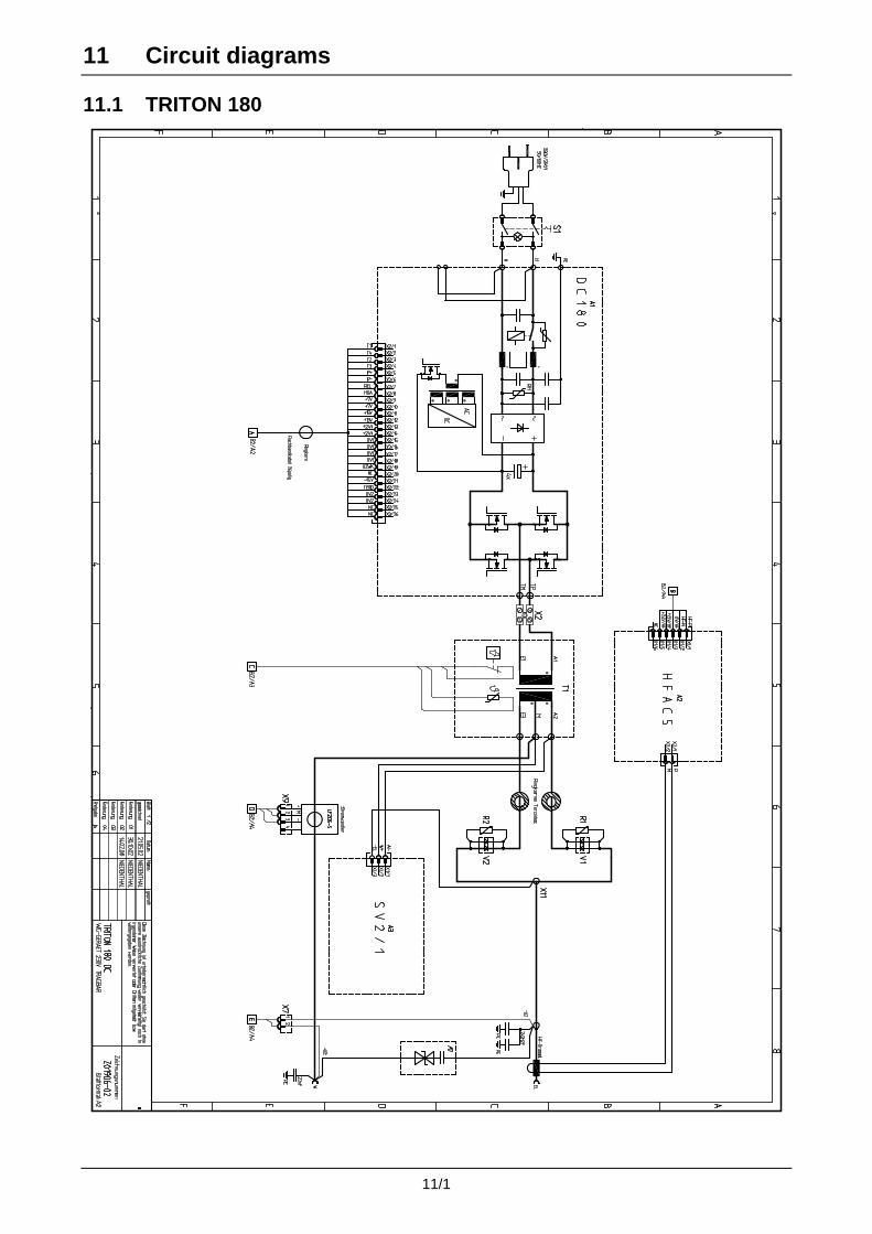
11 Circuit diagrams
11/1
11.1 TRITON 180

11 Circuit diagrams
11/2
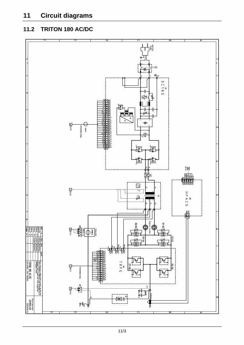
11 Circuit diagrams
11/3
11.2 TRITON 180 AC/DC

11 Circuit diagrams
11/4

11 Circuit diagrams
11/5
11.3 TRITON 220 DC

11 Circuit diagrams
11/6
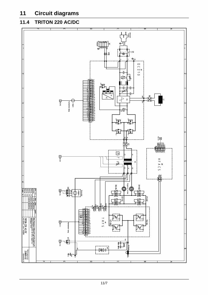
11 Circuit diagrams
11/7
11.4 TRITON 220 AC/DC

11 Circuit diagrams
11/8