operating instructions i/p signal converter 42/18-46-en ... · 42/18-46-en 11.2007 rev. g ... a use...
TRANSCRIPT
Operating Instructions 42/18-46-EN
I/P signal converterTEIP11-PS
Pos: 1 /Titelblätter / Copyright/BA-IA/Aktorik/I/P Signalumformer/Titelblatt TEIP11-PS @ 12\mod_1186486310562_3101.doc @ 112807
Pos: 2 /======= Seitenumbruch ======== @ 0\mod_1126532365768_3101.doc @ 3830
Blinder Text
2 TEIP11-PS 42/18-46-EN
Pos: 3 /Titelblätter / Copyright/Copyright-Seite @ 0\mod_1138781938968_3101.doc @ 3122
I/P signal converter
TEIP11-PS
Operating Instructions 42/18-46-EN
11.2007
Rev. G
Manufacturer: ABB Automation Products GmbH Schillerstraße 72 32425 Minden Germany Tel.: +49 551 905-534 Fax: +49 551 905-555 [email protected]
© Copyright 2007 by ABB Automation Products GmbH Subject to change without notice
This document is protected by copyright. It assists the user with the safe and efficient operation of the device. The contents may not be copied or reproduced in whole or in excerpts without prior approval of the copyright holder.
Pos: 4 /Inhaltsverzeichnis/Inhaltsverzeichnis für alle Dokumente @ 0\mod_1138710310890_3101.doc @ 3129 Contents
Contents
42/18-46-EN TEIP11-PS 3
1 Safety....................................................................................................................................................................5
1.1 General Safety Information ............................................................................................................................5 1.2 Intended use...................................................................................................................................................5 1.3 Technical limits...............................................................................................................................................5 1.4 Warranty provision .........................................................................................................................................6 1.5 Labels and symbols........................................................................................................................................6
1.5.1 Symbols and warnings ............................................................................................................................6 1.5.2 Name plate..............................................................................................................................................7
1.6 Operator liability .............................................................................................................................................7 1.7 Personnel qualification ...................................................................................................................................7 1.8 Returning devices...........................................................................................................................................8 1.9 Disposal..........................................................................................................................................................8
1.9.1 Information on WEEE directive 2002/96/EC (Waste Electrical and Electronic Equipment) ...................8 1.10 Transport safety information ..........................................................................................................................8 1.11 Storage conditions..........................................................................................................................................9 1.12 Installation safety information.........................................................................................................................9 1.13 Electrical installation safety information .........................................................................................................9
2 Explosion-protection safety precautions........................................................................................................10 3 Design and function..........................................................................................................................................12 4 Installation..........................................................................................................................................................14
4.1 Operating conditions at installation site........................................................................................................14 4.2 Delivery scope..............................................................................................................................................14 4.3 Mounting the model with control room housing for rail mounting ................................................................14 4.4 Mounting the model with control room housing for block mounting.............................................................15 4.5 Mounting the model with the plastic field housing unit.................................................................................16 4.6 Mounting the model with aluminum or stainless steel field housing unit .....................................................17
5 Electrical connection ........................................................................................................................................18 5.1 Signal cables ................................................................................................................................................18 5.2 Cable glands ................................................................................................................................................18 5.3 Position of the terminals ...............................................................................................................................19 5.4 Connection ...................................................................................................................................................19
6 Pneumatic connection ......................................................................................................................................20 7 Startup Operation ..............................................................................................................................................20 8 Maintenance.......................................................................................................................................................21
8.1 Replacing the filter element..........................................................................................................................21 8.2 Readjusting the signal conversion ...............................................................................................................22
9 Explosion-protection relevant information.....................................................................................................23 10 Technical data....................................................................................................................................................24
10.1 Input (electric)...............................................................................................................................................24
Contents
4 TEIP11-PS 42/18-46-EN
10.2 Output (pneumatic).......................................................................................................................................24 10.3 Power supply (pneumatic)............................................................................................................................24 10.4 Transmission data and influences................................................................................................................24 10.5 Operating conditions at installation site........................................................................................................24 10.6 Environmental capabilities ...........................................................................................................................24 10.7 Design for rail mounting ...............................................................................................................................25 10.8 Design for block mounting............................................................................................................................25 10.9 Design for field-mount housing (plastic).......................................................................................................25 10.10 Design for field-mount housing (aluminum / stainless steel)........................................................................26 10.11 Accessories ..................................................................................................................................................26 10.12 Spare parts...................................................................................................................................................26 10.13 Dimensioned drawings.................................................................................................................................27
10.13.1 Design for control room housing unit for rail mounting .........................................................................27 10.13.2 Control room housing unit for block mounting ......................................................................................28 10.13.3 Design for field-mount housing (plastic)................................................................................................29 10.13.4 Aluminum or stainless steel field-mount housing unit...........................................................................30
11 Appendix ............................................................................................................................................................31 11.1 Certificates ...................................................................................................................................................31 11.2 Permits and certifications .............................................................................................................................46
12 Index ...................................................................................................................................................................48
Safety
42/18-46-EN TEIP11-PS 5
Pos: 5 /======= Seitenumbruch ======== @ 0\mod_1126532365768_3101.doc @ 3830 Pos: 6.1 /Überschriften/1/S - U/Sicherheit @ 0\mod_1129703894050_3101.doc @ 3168
1 Safety Pos: 6.2 /Sicherheit/Allgemein/Allgemeines zur Sicherheit @ 0\mod_1129703939516_3101.doc @ 3260
1.1 General Safety Information
The “Safety” chapter provides an overview of the safety aspects to be observed for the operation of the device.
The device is built based on state-of-the-art technology and is operationally safe. It was tested and left the factory in a proper state. The requirements in the manual as well as the documentation and certificates must be observed and followed in order to maintain this state for the period of operation.
The general safety requirements must be complied with completely during operation of the device. In addition to the general information, the individual chapters of the manual contain descriptions about processes or procedural instructions with specific safety information.
Only the observance of all safety information enables the optimal protection of personnel as well as the environment from hazards and the safe and trouble-free operation of the device.
Pos: 6.3 /Sicherheit/Aktorik/I/P Signalumformer/TEIP11-PS/Bestimmungsgemäße Verwendung @ 12\mod_1186652885796_3101.doc @ 113303
1.2 Intended use
The TEIP11-PS is used to control pneumatic actuators or pneumatic positioners for positioning valves. It also converts input current proportionally into a compressed air signal. The TEIP11-PS may be used in accordance with Explosion-protection relevant, page 23 as well as Technical data, page 24. All other use is improper use.
Pos: 6.4 /Sicherheit/Allgemein/Hinweis zur bestimmungswidrigren Verwendung (Wartung/Reparatur) @ 0\mod_1129707002440_3101.doc @ 3240
Repairs, alterations and enhancements or the installation of replacement parts is only permissible as far as described in the manual. Further actions must be verified with ABB Automation Products GmbH. Excluded from this are repairs performed by ABB-authorized specialist shops.
Pos: 6.5 /Sicherheit/Temperatur/Allgemein/Technische Grenzwerte (Temperatur) @ 0\mod_1140156564953_3101.doc @ 3252
1.3 Technical limits
The device is designed for use exclusively within the stated values on the name plate and in the technical specifications (see "Technical Specifications” chapter and/or data sheet). These must be complied with accordingly, e.g.:
• The maximum operating temperature may not be exceeded.
• The permitted operating temperature may not be exceeded.
• The housing protection system must be observed.
Pos: 6.6 /======= Seitenumbruch ======== @ 0\mod_1126532365768_3101.doc @ 3830
Safety
6 TEIP11-PS 42/18-46-EN
Pos: 6.7 /Sicherheit/Allgemein/Gewährleistungsbestimmungen @ 0\mod_1129706207246_3101.doc @ 3261
1.4 Warranty provision
A use contrary to the device’s stipulated use, disregarding of this manual, the use of under-qualified personnel as well as unauthorized alterations excludes the manufacturer of liability from any resulting damages. The manufacturer’s warranty expires.
Pos: 6.8 /Überschriften/1.1/1-spaltig/S - U/Schilder und Symbole @ 0\mod_1129721947139_3101.doc @ 3204
1.5 Labels and symbols Pos: 6.9 /Sicherheit/Allgemein/Symbole und Signalwörter @ 0\mod_1129716750196_3101.doc @ 3244
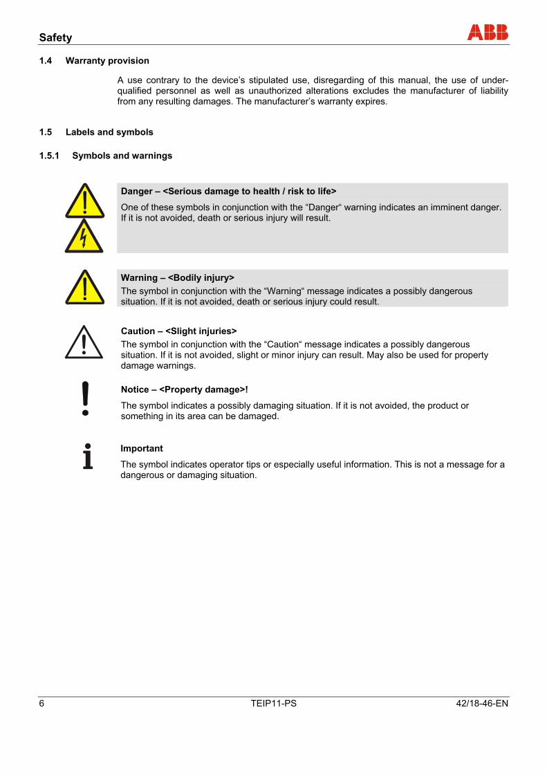
1.5.1 Symbols and warnings
Danger – <Serious damage to health / risk to life>
One of these symbols in conjunction with the “Danger“ warning indicates an imminent danger. If it is not avoided, death or serious injury will result.
Warning – <Bodily injury> The symbol in conjunction with the “Warning“ message indicates a possibly dangerous situation. If it is not avoided, death or serious injury could result.
Caution – <Slight injuries> The symbol in conjunction with the “Caution“ message indicates a possibly dangerous situation. If it is not avoided, slight or minor injury can result. May also be used for property damage warnings.
Notice – <Property damage>!
The symbol indicates a possibly damaging situation. If it is not avoided, the product or something in its area can be damaged.
Important
The symbol indicates operator tips or especially useful information. This is not a message for a dangerous or damaging situation.
Pos: 6.10 /======= Seitenumbruch ======== @ 0\mod_1126532365768_3101.doc @ 3830
Safety
42/18-46-EN TEIP11-PS 7
Pos: 6.11 /Überschriften/1.1.1/1-spaltig/Typenschild @ 0\mod_1140617210906_3101.doc @ 3227
1.5.2 Name plate Pos: 6.12 /Sicherheit/Aktorik/I/P Signalumformer/TEIP11-PS/Typenschild @ 12\mod_1186653078296_3101.doc @ 113326
M00348
1
1
2
2
3
3
4 45
5
66
Kennlinie/Action:Instr.-No.:
Luft/Air:
I/P-Umformer/Converter
Order No.:TEIP11-PS
ABB AutomationMade in Germany
Instr.-No.:Kennlinie/Action:
ABB AutomationMade in Germany
I/P-Umformer/Converter
Order No.:
Luft/Air:
TEIP11-PS
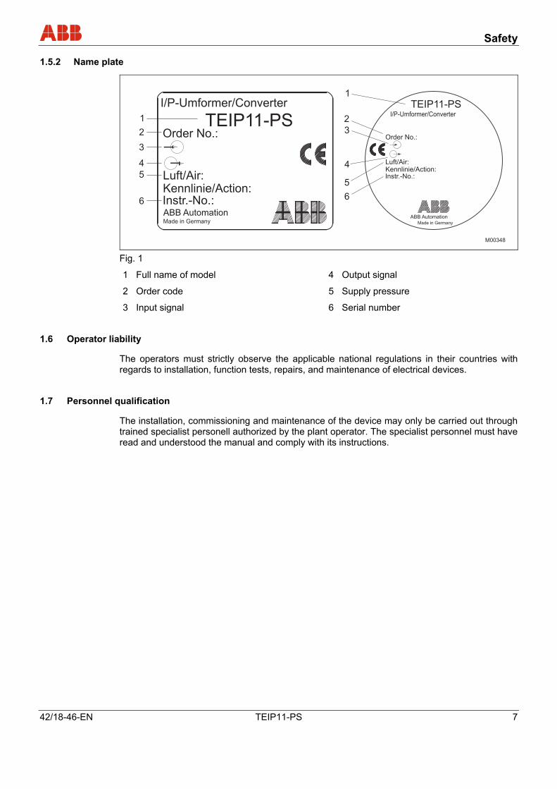
Fig. 1
1 Full name of model 4 Output signal
2 Order code 5 Supply pressure
3 Input signal 6 Serial number
Pos: 6.13 /Sicherheit/Aktorik/Allgemein/Pflichten des Betreibers @ 10\mod_1181723170562_3101.doc @ 105157
1.6 Operator liability
The operators must strictly observe the applicable national regulations in their countries with regards to installation, function tests, repairs, and maintenance of electrical devices.
Pos: 6.14 /Sicherheit/Allgemein/Organisatorische Maßnahmen/Qualifikation des Personals @ 0\mod_1129728800194_3101.doc @ 3247
1.7 Personnel qualification
The installation, commissioning and maintenance of the device may only be carried out through trained specialist personell authorized by the plant operator. The specialist personnel must have read and understood the manual and comply with its instructions.
Pos: 6.15 /======= Seitenumbruch ======== @ 0\mod_1126532365768_3101.doc @ 3830
Safety
8 TEIP11-PS 42/18-46-EN
Pos: 6.16 /Sicherheit/Allgemein/Organisatorische Maßnahmen/Rücksendung von Geräten @ 0\mod_1129730744499_3101.doc @ 3248
1.8 Returning devices
Use the original packaging or a suitably secure packaging for returning the device for repair or for recalibration. Include the properly filled out return form (see attachment) with the device.
According to EC guidelines for hazardous materials, the owner of hazardous waste is responsible for its disposal or must observe the following regulations for its shipping:
All delivered devices to ABB Automation Products GmbH must be free from any hazardous materials (acids, alkali, solvents, etc.).
Pos: 6.17 /Sicherheit/Allgemein/Organisatorische Maßnahmen/Entsorgung @ 10\mod_1176447410937_3101.doc @ 81544
1.9 Disposal
ABB Automation Products GmbH actively promotes environmental consciousness and has an operational management system in accordance with DIN EN ISO 9001:2000, EN ISO 14001:2004 and OHSAS 18001. Our products and solutions should have minimum impact on the environment and persons during manufacture, storage, transport, use and disposal.
This includes the environmentally friendly use of natural resources. Through its publications ABB conducts an open dialog with the public.
This product/solution is manufactured from materials that can be reused by specialized recycling companies.
1.9.1 Information on WEEE directive 2002/96/EC (Waste Electrical and Electronic Equipment)
This product/solution is not subject to the WEEE directive 2002/96/EC and relevant national laws (e.g., ElektroG in Germany).
Dispose of the product/solution directly in a specialized recycling facility and do not use the municipal garbage. Only privately used products may be disposed of in the municipal garbage according to the WEEE directive 2002/96/EC. Proper disposal prevents negative effects on people and the environment, and supports the reuse of valuable raw materials.
If it is not possible to dispose of old equipment properly, ABB Service can accept and dispose of returns for a fee.
Pos: 6.18 /Überschriften/1.1/1-spaltig/S - U/Sicherheitshinweise zum Transport @ 0\mod_1140166475703_3101.doc @ 3206
1.10 Transport safety information Pos: 6.19 /Transport/Allgemein/Prüfung @ 0\mod_1129815371197_3101.doc @ 3317
Check the devices for possible damage that may have occurred from improper transport. Damages in transit must be recorded on the transport documents. All claims for damages must be claimed without delay against the shipper and before the installation.
Pos: 6.20 /Überschriften/1.1/1-spaltig/J - L/Lagerbedingungen @ 8\mod_1176907016921_3101.doc @ 84229
Safety
42/18-46-EN TEIP11-PS 9
1.11 Storage conditions Pos: 6.21 /Sicherheit/Aktorik/I/P Signalumformer/TEIP11-PS/Lagerbedingungen @ 12\mod_1186653491453_3101.doc @ 113372
The units must be stored in dry and dust-free conditions.
The storage temperature should be between -20 °C (-4 °F) and 70 °C (158 °F).
The storage time is basically indefinite, however, the warranty conditions stipulated in the order confirmation of the supplier are valid.
Pos: 6.22 /Überschriften/1.1/1-spaltig/S - U/Sicherheitshinweise zur Montage @ 0\mod_1140166528109_3101.doc @ 3208
1.12 Installation safety information Pos: 6.23 /Sicherheit/Aktorik/I/P Signalumformer/TEIP11-PS/Sicherheitshinweise zur Montage @ 12\mod_1186653584453_3101.doc @ 113395
• Only qualified specialists who have been trained for these tasks are authorized to mount and adjust the I/P signal converter, and to make the electrical connection.
• When working on the I/P signal converter always observe the locally valid accident prevention regulations and the regulations concerning the construction of technical installations.
Pos: 6.24 /Überschriften/1.1/1-spaltig/S - U/Sicherheitshinweise zur elektrischen Installation @ 0\mod_1140166567843_3101.doc @ 3207
1.13 Electrical installation safety information Pos: 6.25 /Sicherheit/Aktorik/I/P Signalumformer/TEIP11-PS/Wichtiger Hinweis zur elektrischen Installation @ 12\mod_1186654404703_3101.doc @ 113418
Important
The I/P signal converter has been manufactured and tested in accordance with DIN EN 61010-1 “Safety Requirements for Electronic Equipment” and has been supplied in a safe condition.
Pos: 6.26 /Sicherheit/Temperatur/Allgemein/Sicherheitshinweise zur elektrischen Installation (Temperatur) (2007-10-09 13:47:14) @ 0\mod_1140164437968_3101.doc @ 3268
The electrical connection may only be performed by authorized specialist personnel according to the electrical plans.
Observe the electrical connection information in the manual, otherwise the electrical protection can be affected. The secure isolation of contact-dangerous electrical circuits is only guaranteed when the connected devices fulfil the requirements of the DIN VDE 0106 T.101 (basic requirements for secure isolation). For secure isolation, run the supply lines separated from contact-dangerous electrical circuits or additionally isolate them.
Pos: 7 /======= Seitenumbruch ======== @ 0\mod_1126532365768_3101.doc @ 3830
Explosion-protection safety precautions
10 TEIP11-PS 42/18-46-EN
Pos: 8.1 /Überschriften/1/D - F/Ex-technische Sicherheitshinweise @ 9\mod_1181416415484_3101.doc @ 102826
2 Explosion-protection safety precautions Pos: 8.2 /Ex-technische Sicherheitshinweise/Aktorik/I/P Signalumformer/TEIP11-PS/Ex-technische Sicherheitshinweise @ 12\mod_1186664094343_3101.doc @ 113513
Requirements/conditions for safe use of explosion-proof I/P signal converters (type doc. 900771)
Important
Prior to mounting check to ensure that the specifications in terms of safety and control applicable to the I/P signal converter will not be exceeded.
• When making the electrical connections observe the specifications in the section "Technical
data" and the specifications in the explosion protection certificate.
• The device must be supplied with instrument air that is free of oil, water and dust. Do not use flammable gas nor oxygen or oxygen-enriched gas.
• Do not open the device immediately after switch-off. Wait for at least 4 minutes.
Warning - Potential damage to parts!
Handle the cover with care. Otherwise, the thread may be damaged, canceling the explosion protection.
Important
Use only cable glands with full Ex d approval for EEx d operation. • Secure the cable and tube entries against turning and loosening by using security adhesive
of medium strength.
• If the signal converter is used at an ambient temperature above 60 °C (140°F) or below -20 °C (-4 °F), use cable entries and cables approved for a service temperature corresponding to the maximum ambient temperature increased by 10 K or corresponding to the minimum ambient temperature, respectively.
Warning - Potential damage to parts!
Devices that comply in new condition with “Ex ia” and "Ex d" protection classes should not be used in intrinsically safe "Ex ia" applications once they have been commissioned and used in an environment with “Ex d” protection, since the electronics may have been damaged.
This is why the instruments must be marked permanently (e.g., cross out or paste over Ex i).
Explosion-protection safety precautions
42/18-46-EN TEIP11-PS 11
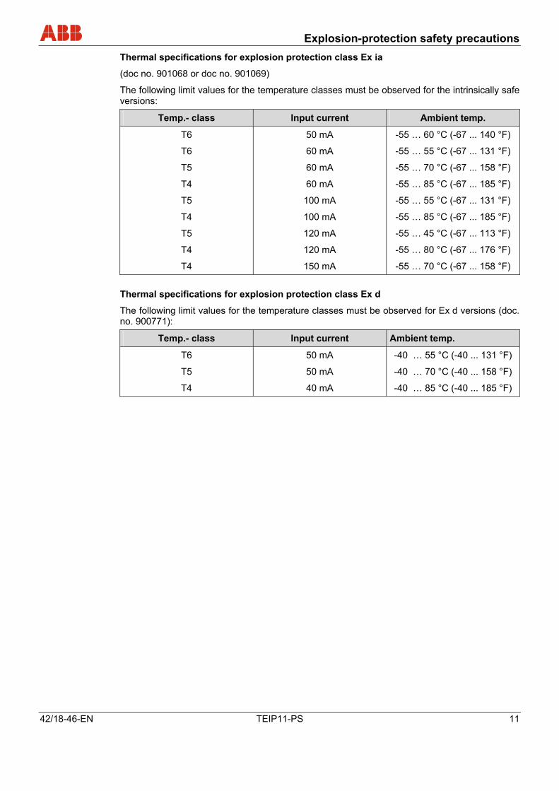
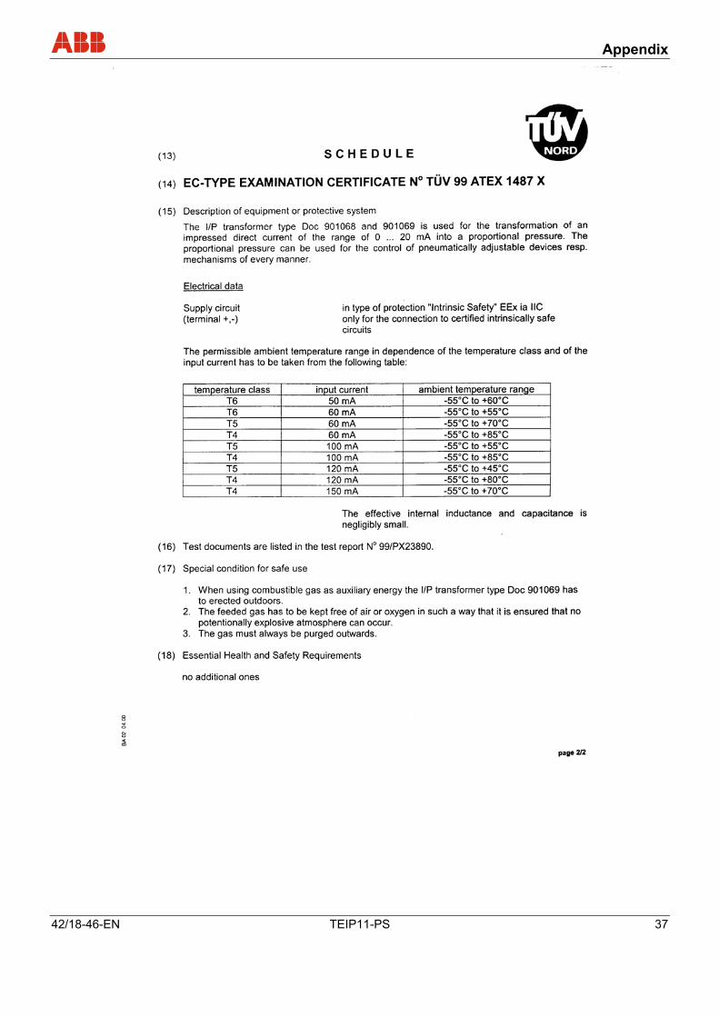
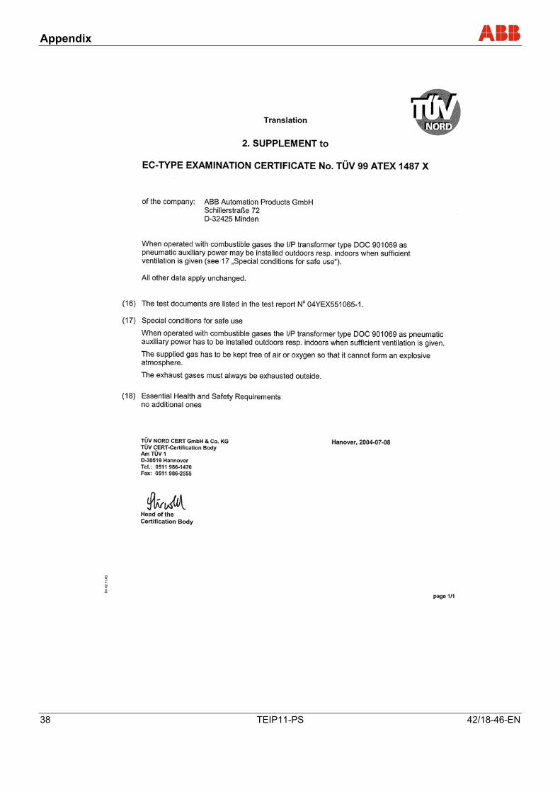
Thermal specifications for explosion protection class Ex ia
(doc no. 901068 or doc no. 901069)
The following limit values for the temperature classes must be observed for the intrinsically safe versions:
Temp.- class Input current Ambient temp.
T6
T6
T5
T4
T5
T4
T5
T4
T4
50 mA
60 mA
60 mA
60 mA
100 mA
100 mA
120 mA
120 mA
150 mA
-55 … 60 °C (-67 ... 140 °F)
-55 … 55 °C (-67 ... 131 °F)
-55 … 70 °C (-67 ... 158 °F)
-55 … 85 °C (-67 ... 185 °F)
-55 … 55 °C (-67 ... 131 °F)
-55 … 85 °C (-67 ... 185 °F)
-55 … 45 °C (-67 ... 113 °F)
-55 … 80 °C (-67 ... 176 °F)
-55 … 70 °C (-67 ... 158 °F) Thermal specifications for explosion protection class Ex d
The following limit values for the temperature classes must be observed for Ex d versions (doc. no. 900771):
Temp.- class Input current Ambient temp.
T6
T5
T4
50 mA
50 mA
40 mA
-40 … 55 °C (-40 ... 131 °F)
-40 … 70 °C (-40 ... 158 °F)
-40 … 85 °C (-40 ... 185 °F)
Pos: 9 /======= Seitenumbruch ======== @ 0\mod_1126532365768_3101.doc @ 3830
Design and function
12 TEIP11-PS 42/18-46-EN
Pos: 10.1 /Überschriften/1/A - C/Aufbau und Funktion @ 0\mod_1129797620733_3101.doc @ 3140
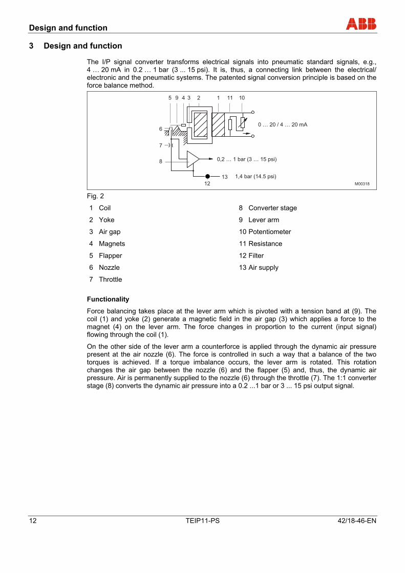
3 Design and function Pos: 10.2 /Aufbau und Funktion/Aktorik/I/P Signalumformer/TEIP11-PS/Aufbau und Funktion @ 12\mod_1186665459718_3101.doc @ 113652
The I/P signal converter transforms electrical signals into pneumatic standard signals, e.g., 4 … 20 mA in 0.2 … 1 bar (3 ... 15 psi). It is, thus, a connecting link between the electrical/ electronic and the pneumatic systems. The patented signal conversion principle is based on the force balance method.
M00318
5
6
7
8
12
13
9 4 3 2 1 11 10
0 … 20 / 4 … 20 mA
0,2 … 1 bar (3 … 15 psi)
1,4 bar (14.5 psi)
Fig. 2
1 Coil 8 Converter stage
2 Yoke 9 Lever arm
3 Air gap 10 Potentiometer
4 Magnets 11 Resistance
5 Flapper 12 Filter
6 Nozzle 13 Air supply
7 Throttle Functionality
Force balancing takes place at the lever arm which is pivoted with a tension band at (9). The coil (1) and yoke (2) generate a magnetic field in the air gap (3) which applies a force to the magnet (4) on the lever arm. The force changes in proportion to the current (input signal) flowing through the coil (1).
On the other side of the lever arm a counterforce is applied through the dynamic air pressure present at the air nozzle (6). The force is controlled in such a way that a balance of the two torques is achieved. If a torque imbalance occurs, the lever arm is rotated. This rotation changes the air gap between the nozzle (6) and the flapper (5) and, thus, the dynamic air pressure. Air is permanently supplied to the nozzle (6) through the throttle (7). The 1:1 converter stage (8) converts the dynamic air pressure into a 0.2 ...1 bar or 3 ... 15 psi output signal.
Design and function
42/18-46-EN TEIP11-PS 13
Supply air
During operation the pneumatic unit needs a steady supply of air (13) according to device specifications. Zero adjustment can be done on the tension band suspension (9), and range adjustment on the potentiometer (10). Special features
Special features of the I/P signal converter are its relatively small dimensions and high operational stability when subjected to shock and vibration. The stability is due to the light weight (only 100 mg) of the moving system, which consists of the lever arm with the magnet (4) and the flapper (5) with balancing weight.
Filter
The air filter (12) prevents malfunctions caused by polluted air. Note that the filter capacity is only sufficient for collecting dirt that occurs occasionally (e.g. residual dirt in the air pipes at first use). It is no substitute for proper air conditioning. Deliverables
For details on the deliverable signal converter models and their accessories, please refer to data sheet 10/18-0.10 EN, which also includes the catalog numbers of the individual items.
Pos: 11 /======= Seitenumbruch ======== @ 0\mod_1126532365768_3101.doc @ 3830
Installation
14 TEIP11-PS 42/18-46-EN
Pos: 12.1 /Überschriften/1/M - O/Montage @ 0\mod_1140519732218_3101.doc @ 3159
4 Installation Pos: 12.2 /Überschriften/1.1/1-spaltig/A - C/Betriebsbedingungen am Installationsort @ 12\mod_1186668341281_3101.doc @ 113771
4.1 Operating conditions at installation site Pos: 12.3 /Montage/Aktorik/I/P Signalumformer/TEIP11-PS/Betriebsbedingungen am Installationsort @ 12\mod_1186667949031_3101.doc @ 113748
Important
Prior to mounting check to ensure that the specifications in terms of safety and control applicable to the I/P signal converter will not be exceeded at the installation location.
See chapter Technical data, page 24 .
Pos: 12.4 /Überschriften/1.1/1-spaltig/J - L/Lieferumfang @ 12\mod_1186668540000_3101.doc @ 113794
4.2 Delivery scope Pos: 12.5 /Montage/Aktorik/I/P Signalumformer/TEIP11-PS/Lieferumfang @ 12\mod_1186668235437_3101.doc @ 113817
• Check the delivery for completeness, signs of damage, model and scope immediately upon arrival.
• Check whether the delivery is in accordance with your order. Accessories
The following loose accessories are delivered with the unit as extra items:
• Mounting bracket for the aluminum or stainless steel field housing unit (for wall or 2" pipe mounting)
• Cable entry for signal converter with “EEx d” explosion protection
Pos: 12.6 /Überschriften/1.1/1-spaltig/M - O/Montage des Wartengehäuses für Tragschienenmontage @ 12\mod_1186730863718_3101.doc @ 114364
4.3 Mounting the model with control room housing for rail mounting Pos: 12.7 /Montage/Aktorik/I/P Signalumformer/TEIP11-PS/Montage des Wartengehäuses für Tragschienenmontage @ 12\mod_1186669065687_3101.doc @ 113840
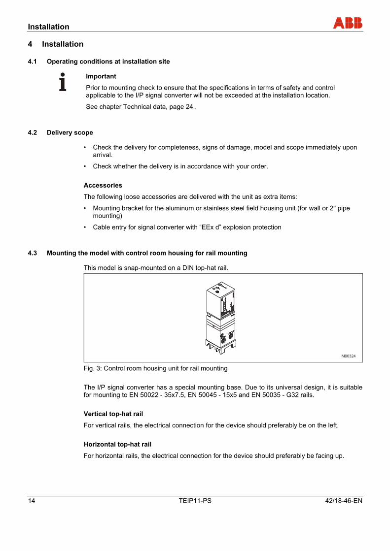
This model is snap-mounted on a DIN top-hat rail.
M00324 Fig. 3: Control room housing unit for rail mounting The I/P signal converter has a special mounting base. Due to its universal design, it is suitable for mounting to EN 50022 - 35x7.5, EN 50045 - 15x5 and EN 50035 - G32 rails. Vertical top-hat rail
For vertical rails, the electrical connection for the device should preferably be on the left. Horizontal top-hat rail
For horizontal rails, the electrical connection for the device should preferably be facing up.
Pos: 12.8 /======= Seitenumbruch ======== @ 0\mod_1126532365768_3101.doc @ 3830
Installation
42/18-46-EN TEIP11-PS 15
Pos: 12.9 /Überschriften/1.1/1-spaltig/M - O/Montage des Wartengehäuses für Blockmontage @ 12\mod_1186730744937_3101.doc @ 114341
4.4 Mounting the model with control room housing for block mounting Pos: 12.10 /Montage/Aktorik/I/P Signalumformer/TEIP11-PS/Montage des Wartengehäuses für Blockmontage @ 12\mod_1186669506218_3101.doc @ 113863
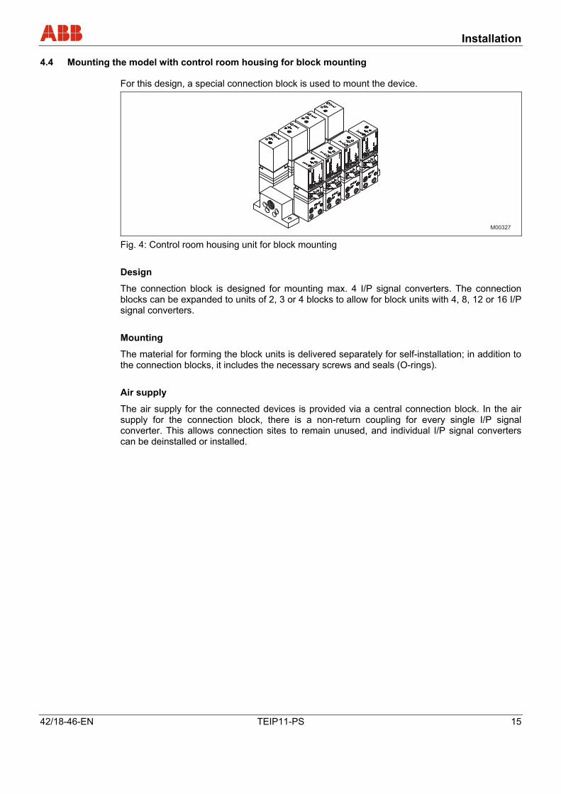
For this design, a special connection block is used to mount the device.
M00327 Fig. 4: Control room housing unit for block mounting Design
The connection block is designed for mounting max. 4 I/P signal converters. The connection blocks can be expanded to units of 2, 3 or 4 blocks to allow for block units with 4, 8, 12 or 16 I/P signal converters. Mounting
The material for forming the block units is delivered separately for self-installation; in addition to the connection blocks, it includes the necessary screws and seals (O-rings). Air supply
The air supply for the connected devices is provided via a central connection block. In the air supply for the connection block, there is a non-return coupling for every single I/P signal converter. This allows connection sites to remain unused, and individual I/P signal converters can be deinstalled or installed.
Pos: 12.11 /======= Seitenumbruch ======== @ 0\mod_1126532365768_3101.doc @ 3830
Installation
16 TEIP11-PS 42/18-46-EN
Pos: 12.12 /Überschriften/1.1/1-spaltig/M - O/Montage des Feldgehäuses aus Kunststoff @ 12\mod_1186730640828_3101.doc @ 114318
4.5 Mounting the model with the plastic field housing unit Pos: 12.13 /Montage/Aktorik/I/P Signalumformer/TEIP11-PS/Montage des Feldgehäuses aus Kunststoff @ 12\mod_1186670106984_3101.doc @ 113886
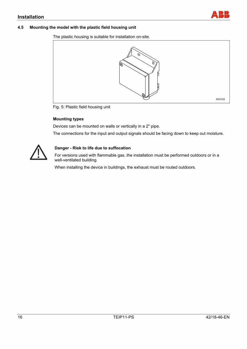
The plastic housing is suitable for installation on-site.
M00326 Fig. 5: Plastic field housing unit Mounting types
Devices can be mounted on walls or vertically in a 2" pipe.
The connections for the input and output signals should be facing down to keep out moisture.
Danger - Risk to life due to suffocation
For versions used with flammable gas, the installation must be performed outdoors or in a well-ventilated building.
When installing the device in buildings, the exhaust must be routed outdoors.
Pos: 12.14 /======= Seitenumbruch ======== @ 0\mod_1126532365768_3101.doc @ 3830
Installation
42/18-46-EN TEIP11-PS 17
Pos: 12.15 /Überschriften/1.1/1-spaltig/M - O/Montage des Feldgehäuses aus Aluminium / Edelstahl @ 12\mod_1186730484328_3101.doc @ 114295
4.6 Mounting the model with aluminum or stainless steel field housing unit Pos: 12.16 /Montage/Aktorik/I/P Signalumformer/TEIP11-PS/Montage des Feldgehäuses aus Aluminium / Edelstahl @ 12\mod_1186670875796_3101.doc @ 113909
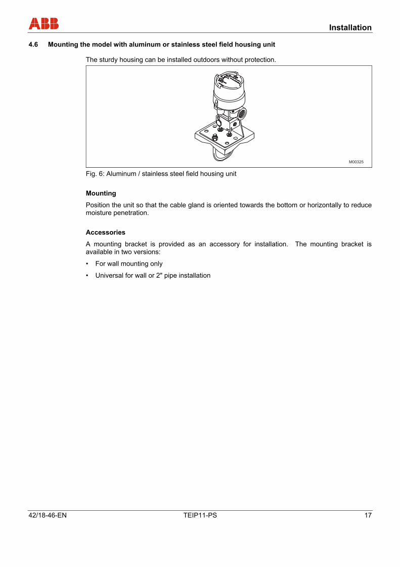
The sturdy housing can be installed outdoors without protection.
M00325 Fig. 6: Aluminum / stainless steel field housing unit Mounting
Position the unit so that the cable gland is oriented towards the bottom or horizontally to reduce moisture penetration. Accessories
A mounting bracket is provided as an accessory for installation. The mounting bracket is available in two versions:
• For wall mounting only
• Universal for wall or 2" pipe installation
Pos: 13 /======= Seitenumbruch ======== @ 0\mod_1126532365768_3101.doc @ 3830
Electrical connection
18 TEIP11-PS 42/18-46-EN
Pos: 14.1 /Überschriften/1/D - F/Elektrischer Anschluss @ 0\mod_1140620471687_3101.doc @ 3143
5 Electrical connection Pos: 14.2 /Elektrischer Anschluss/Aktorik/I/P Signalumformer/TEIP11-PS/Wichtige Hinweise zum elektrischen Anschluss @ 12\mod_1186738899328_3101.doc @ 114872
Important
For electrical installation, the following standards, data and documents must be observed:
• the relevant regulations and safety standards pertaining to the installation and operation of electrical systems.
• the additional regulations, standards and directives governing the installation and operation of explosion-proof systems, if explosion-proof devices are used.
• the values for the electrical connection in section Technical data, page 24.
• for explosion-proof devices also observe the specifications in the explosion protection certificate
Pos: 14.3 /Überschriften/1.1/1-spaltig/S - U/Signalleitung @ 12\mod_1186739171359_3101.doc @ 114987
5.1 Signal cables Pos: 14.4 /Elektrischer Anschluss/Aktorik/I/P Signalumformer/TEIP11-PS/Signalleitung @ 12\mod_1186738978453_3101.doc @ 114895
Do not run signal cables close to power lines.
Important
Power lines produce interference in their near vicinity, which impairs the signals transmitted on the line.
Pos: 14.5 /Überschriften/1.1/1-spaltig/J - L/Kabelverschraubungen @ 8\mod_1173706891046_3101.doc @ 71975
5.2 Cable glands Pos: 14.6 /Elektrischer Anschluss/Aktorik/I/P Signalumformer/TEIP11-PS/Kabelverschraubungen @ 12\mod_1186739038265_3101.doc @ 114918 s
Cable entries of different types are provided:
• Plastic field housing unit
• Pf 11 cable gland
Aluminum or stainless steel field housing unit
• Standard / EEx ia Cable gland ½" NPT
• EEx d Tap hole M20 x 1.5
• FM / CSA "intrinsically safe" / "Explosion proof"
Tap hole ½" NPT
Important
Use only cable glands with full Ex d approval for EEx d operation (partly approved cable glands labeled “U” are NOT sufficient).
Fix the screwed-in Ex d cable gland with glue to secure it against loosening. Loctite 242/243 or similar glues are suitable.
Pos: 14.7 /======= Seitenumbruch ======== @ 0\mod_1126532365768_3101.doc @ 3830
Electrical connection
42/18-46-EN TEIP11-PS 19
Pos: 14.8 /Überschriften/1.1/1-spaltig/J - L/Lage der Anschlussklemmen @ 12\mod_1186739280750_3101.doc @ 115010
5.3 Position of the terminals Pos: 14.9 /Elektrischer Anschluss/Aktorik/I/P Signalumformer/TEIP11-PS/Lage der Anschlussklemmen @ 12\mod_1186739080000_3101.doc @ 114941
The electrical connection is provided by 2-pole screw terminals for cables with a max. cross-sectional area of 2.5 mm2 (14 AWG). For control room housing unit for rail and block mounting
The terminals are located on the side of the housing. Plastic, aluminum or stainless steel field housing unit
The terminals are located inside the housing. The field housing unit must be opened to connect the cable.
Pos: 14.10 /Überschriften/1.1/1-spaltig/A - C/Anschluss @ 12\mod_1186739430406_3101.doc @ 115033
5.4 Connection Pos: 14.11 /Elektrischer Anschluss/Aktorik/I/P Signalumformer/TEIP11-PS/Anschluss @ 12\mod_1186739119843_3101.doc @ 114964
Do not reverse polarity when connecting the cable.
Pos: 15 /======= Seitenumbruch ======== @ 0\mod_1126532365768_3101.doc @ 3830
Pneumatic connection
20 TEIP11-PS 42/18-46-EN
Pos: 16.1 /Überschriften/1/P - R/Pneumatischer Anschluss @ 12\mod_1186733724140_3101.doc @ 114530
6 Pneumatic connection Pos: 16.2 /Pneumatischer Anschluss/Aktorik/I/P Signalumformer/TEIP11-PS/Pneumatischer Anschluss @ 12\mod_1186733645421_3101.doc @ 114387
Important
The I/P signal converter must be supplied with instrument air that is free of oil, water and dust.
The purity and oil content should meet the requirements of Class 3 according to DIN/ISO 8573-1.
The pressure dew point should be 10 K under the lowest operating temperature.
For versions with plastic housing and when used with flammable gas, an additional line must be added to route the gas to a safe site.
The control room housing has 1/8, 1/4 or 3/8 NPT holes (for air supply and output) (see the specifications in section Technical data, page 24).
The connections for air supply and output are marked accordingly.
Warning - Potential damage to parts!
The recommended pipe dimension is 6 x 1 mm. Dust, splinters or any other particles must be blown off the pipe before connecting.
The supply pressure for the device has to be set as follows:
For output 0.2 ... 1 bar (3 ... 15 psi)
1,4 ± 0.1 bar (20 ± 1.5 psi)
The max. allowable overload limit for the supply pressure is 4 bar (60 psi).
Warning - Potential damage to parts! Provisions should be made to ensure that in the event of an error the pressure does not rise above 4 bar (60 psi).
Pos: 17.1 /Überschriften/1/G - I/Inbetriebnahme @ 0\mod_1131980668835_3101.doc @ 3150
7 Startup Operation Pos: 17.2 /Inbetriebnahme/Aktorik/I/P Signalumformer/TEIP11-PS/Inbetriebnahme @ 12\mod_1186734638187_3101.doc @ 114622
The I/P signal converter is ready for operation immediately after installation and connection. No further adjustment is required.
Pos: 18 /======= Seitenumbruch ======== @ 0\mod_1126532365768_3101.doc @ 3830
Maintenance
42/18-46-EN TEIP11-PS 21
Pos: 19.1 /Überschriften/1/V - Z/Wartung @ 10\mod_1181642125390_3101.doc @ 103817
8 Maintenance Pos: 19.2 /Wartung / Reparatur/Aktorik/I/P Signalumformer/TEIP11-PS/Wartung, allgemein @ 12\mod_1186734880703_3101.doc @ 114645
Important
Note that the supplied instrument air must be free of oil, water and dust according to DIN/ISO 8573-1 to ensure trouble-free operation. It is recommended to regularly check the built-in textile filter (if present) for the degree of pollution and the signal conversion to see if the values are still within the tolerance.
Pos: 19.3 /Überschriften/1.1/1-spaltig/A - C/Auswechseln des Filtereinsatzes @ 12\mod_1186736735781_3101.doc @ 114734
8.1 Replacing the filter element Pos: 19.4 /Wartung / Reparatur/Aktorik/I/P Signalumformer/TEIP11-PS/Auswechseln des Filtereinsatzes @ 12\mod_1186735003984_3101.doc @ 114688
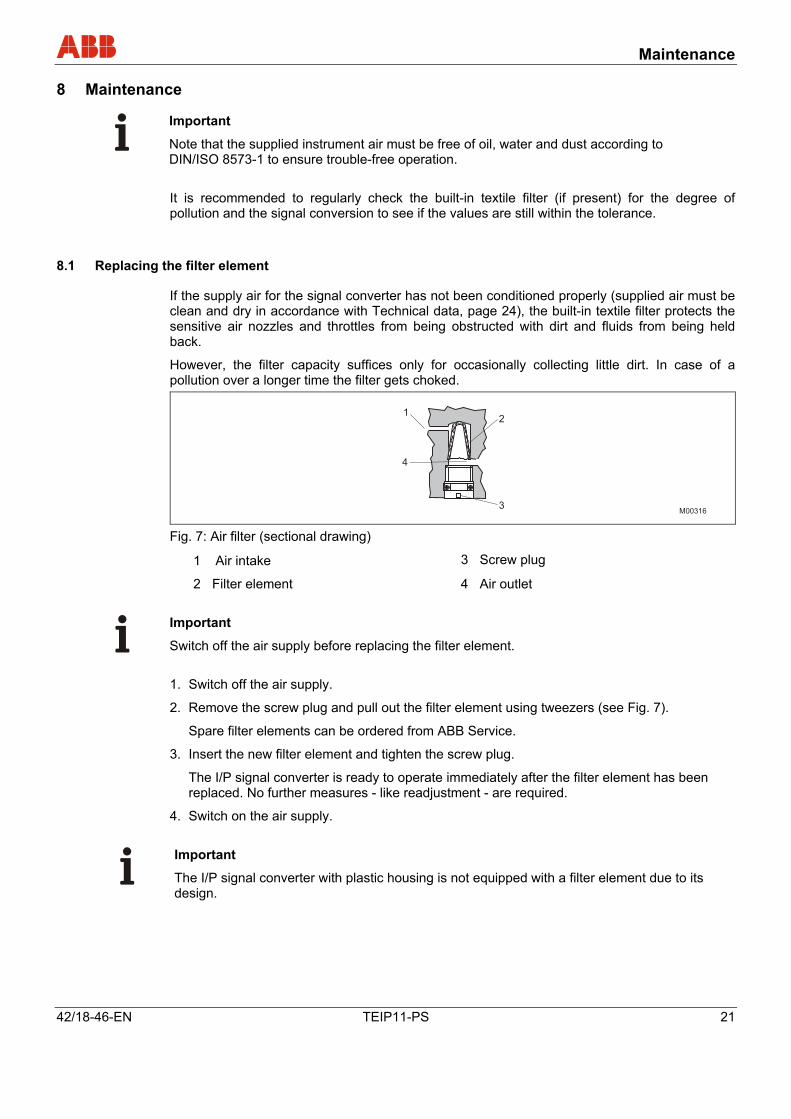
If the supply air for the signal converter has not been conditioned properly (supplied air must be clean and dry in accordance with Technical data, page 24), the built-in textile filter protects the sensitive air nozzles and throttles from being obstructed with dirt and fluids from being held back.
However, the filter capacity suffices only for occasionally collecting little dirt. In case of a pollution over a longer time the filter gets choked.
12
3
4
M00316 Fig. 7: Air filter (sectional drawing)
1 Air intake 3 Screw plug
2 Filter element 4 Air outlet
Important
Switch off the air supply before replacing the filter element. 1. Switch off the air supply.
2. Remove the screw plug and pull out the filter element using tweezers (see Fig. 7).
Spare filter elements can be ordered from ABB Service.
3. Insert the new filter element and tighten the screw plug.
The I/P signal converter is ready to operate immediately after the filter element has been replaced. No further measures - like readjustment - are required.
4. Switch on the air supply.
Important
The I/P signal converter with plastic housing is not equipped with a filter element due to its design.
Pos: 19.5 /======= Seitenumbruch ======== @ 0\mod_1126532365768_3101.doc @ 3830
Maintenance
22 TEIP11-PS 42/18-46-EN
Pos: 19.6 /Überschriften/1.1/1-spaltig/M - O/Nachjustieren der Signalumformung @ 12\mod_1186736966625_3101.doc @ 114757
8.2 Readjusting the signal conversion Pos: 19.7 /Wartung / Reparatur/Aktorik/I/P Signalumformer/TEIP11-PS/Nachjustieren der Signalumformung @ 12\mod_1186736266984_3101.doc @ 114711
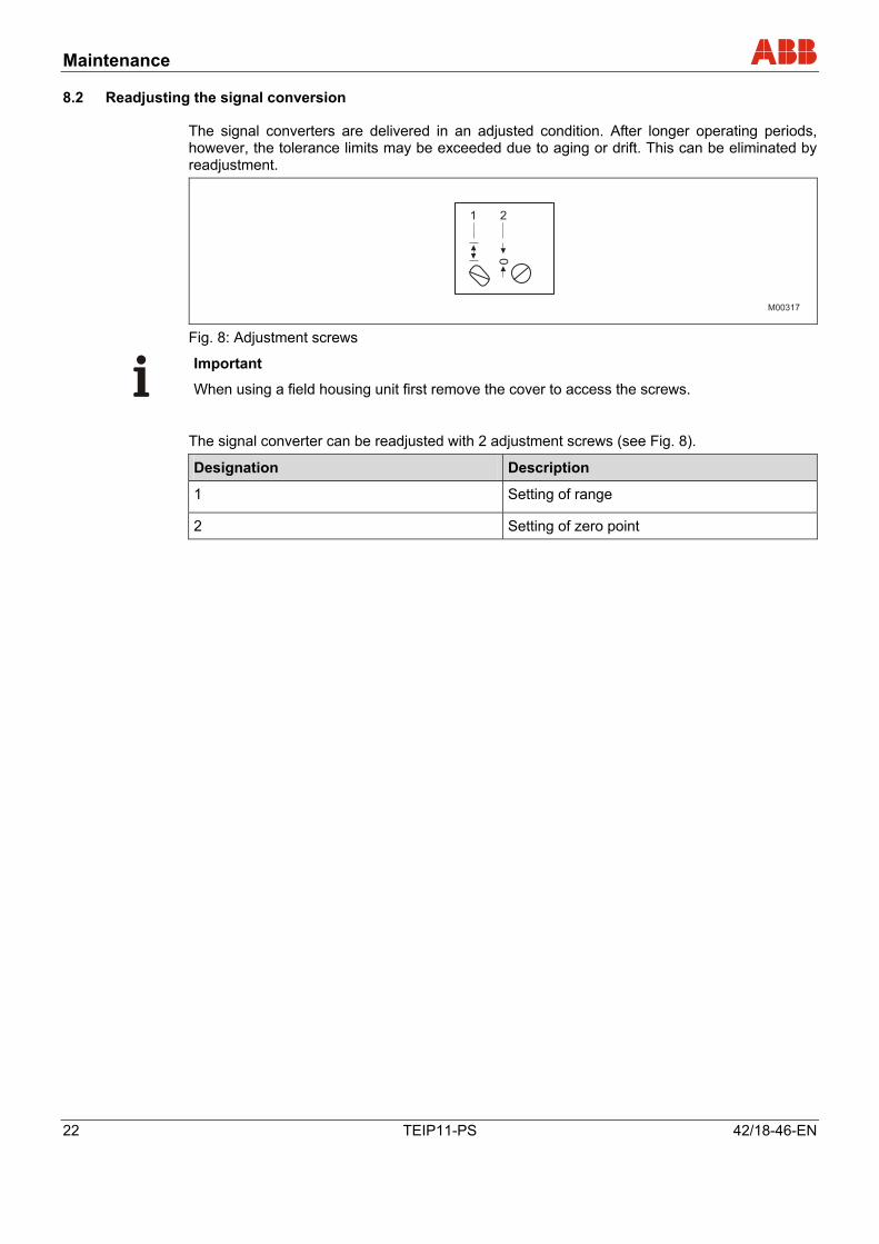
The signal converters are delivered in an adjusted condition. After longer operating periods, however, the tolerance limits may be exceeded due to aging or drift. This can be eliminated by readjustment.
0
1 2
M00317 Fig. 8: Adjustment screws
Important
When using a field housing unit first remove the cover to access the screws.
The signal converter can be readjusted with 2 adjustment screws (see Fig. 8).
Designation Description
1 Setting of range
2 Setting of zero point
Pos: 20 /======= Seitenumbruch ======== @ 0\mod_1126532365768_3101.doc @ 3830
Explosion-protection relevant information
42/18-46-EN TEIP11-PS 23
Pos: 21.1 /Überschriften/1/D - F/Ex-technische Daten @ 0\mod_1132304633775_3101.doc @ 3145
9 Explosion-protection relevant information Pos: 21.2 /==== Wechsel ein- auf zweispaltig ==== @ 0\mod_1130421847171_3101.doc @ 3828 Wechsel ein-auf zweispaltig Pos: 21.3 /Ex-technische Daten/Aktorik/I/P Signalumformer/TEIP11-PS/Explosionsschutz @ 12\mod_1186727524140_3101.doc @ 114392 aE
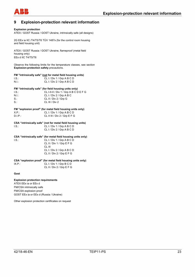
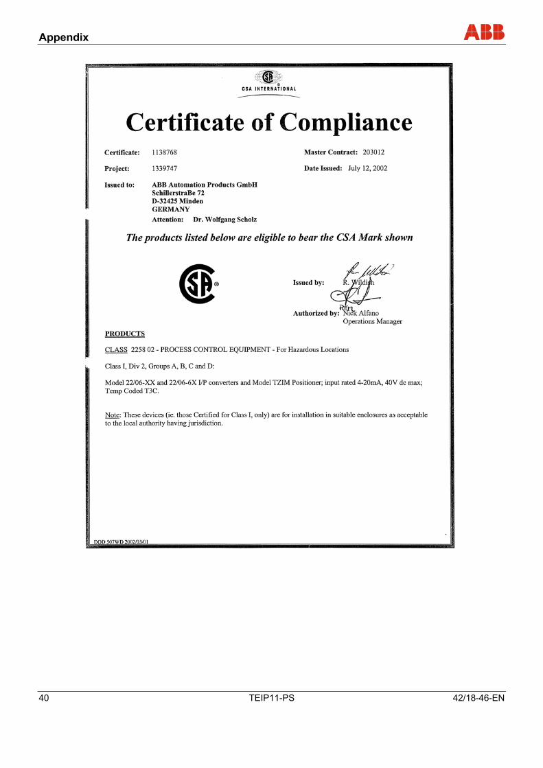
Explosion protection ATEX / GOST Russia / GOST Ukraine, intrinsically safe (all designs) 2G EEx ia IIC /T4/T5/T6 TÜV 1487x (for the control room housing and field housing unit) ATEX / GOST Russia / GOST Ukraine, flameproof (metal field housing only) EEx d IIC T4/T5/T6 Observe the following limits for the temperature classes, see section Explosion-protection safety precautions. FM "intrinsically safe" (not for metal field housing units) I.S.: CL I / Div 1 / Grp A B C D N.I.: CL I / Div 2 / Grp A B C D
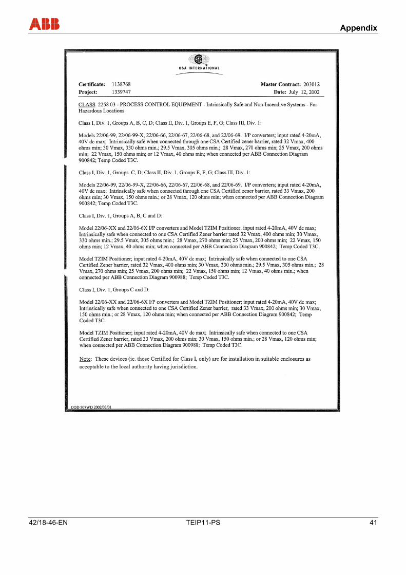
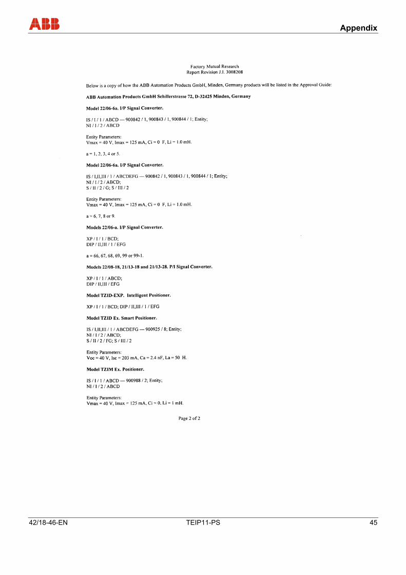
FM “intrinsically safe” (for field housing units only) I.S.: CL I-II-II / Div 1 / Grp A B C D E F G N.I.: CL I / Div 2 / Grp A B C S.: CL II / Div 2 / Grp G S.: CL III / Div 2 FM "explosion proof" (for metal field housing units only) X.P.: CL I / Div 1 / Grp A B C D D.I.P.: CL II III / Div 2 / Grp E F G CSA “intrinsically safe” (not for metal field housing units) I.S.: CL I / Div 1 / Grp A B C D CL I / Div 2 / Grp A B C D CSA “intrinsically safe” (for metal field housing units only) I.S.: CL I / Div 1 / Grp A B C D CL II / Div 1 / Grp E F G CL III CL I / Div 2 / Grp A B C D CL II / Div 2 / Grp E F G CSA “explosion proof” (for metal field housing units only) IX.P.: CL I / Div 1 / Grp B C D CL II / Div 2 / Grp E F G Gost Explosion protection requirements ATEX EEx ia or EEx d FM/CSA intrinsically safe FM/CSA explosion proof GOST EEx ia or EEx d (Russia / Ukraine) Other explosion protection certificates on request
Pos: 21.4 /==== Wechsel zwei- auf einspaltig ==== @ 0\mod_1130421955859_3101.doc @ 3829
Wechsel ein-auf zweispaltig Pos: 22 /======= Seitenumbruch ======== @ 0\mod_1126532365768_3101.doc @ 3830
Technical data
24 TEIP11-PS 42/18-46-EN
Pos: 23.1 /Überschriften/1/S - U/Technische Daten @ 0\mod_1132904574837_3101.doc @ 3169
10 Technical data Pos: 23.2 /==== Wechsel ein- auf zweispaltig ==== @ 0\mod_1130421847171_3101.doc @ 3828 Wechsel ein-auf zweispaltig Pos: 23.3 /Überschriften/1.1/2-spaltig/Eingang (elektrisch) @ 12\mod_1187000581234_3101.doc @ 115086
10.1 Input (electric) Pos: 23.4 /Technische Daten / Datenblatt/Aktorik/I/P Signalumformer/Allgemein/Technische Daten/Eingang (elektrisch) @ 12\mod_1186723987781_3101.doc @ 114055
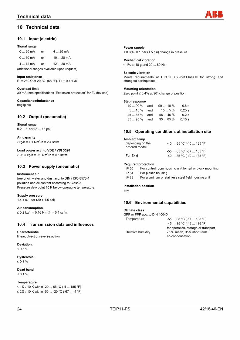
Signal range 0 ... 20 mA or 4 ... 20 mA
0 ... 10 mA or 10 ... 20 mA
4 ... 12 mA or 12 ... 20 mA (additional ranges available upon request) Input resistance Ri = 260 Ω at 20 °C (68 °F), Tk + 0.4 %/K Overload limit 30 mA (see specifications “Explosion protection” for Ex devices) Capacitance/Inductance negligible Pos: 23.5 /Überschriften/1.1/2-spaltig/Ausgang (pneumatisch) @ 12\mod_1187000648781_3101.doc @ 115109
10.2 Output (pneumatic) Pos: 23.6 /Technische Daten / Datenblatt/Aktorik/I/P Signalumformer/TEIP11-PS/Technische Daten/Ausgang (pneumatisch) @ 12\mod_1187000030453_3101.doc @ 115063
Signal range 0.2 ... 1 bar (3 ... 15 psi) Air capacity ≥kg/h = 4.1 Nm3/h = 2.4 scfm Load power acc. to VDE / VDI 3520 ≥ 0.95 kg/h = 0.9 Nm3/h = 0.5 scfm Pos: 23.7 /Überschriften/1.1/2-spaltig/Energieversorgung (pneumatisch) @ 12\mod_1187000735109_3101.doc @ 115132
10.3 Power supply (pneumatic) Pos: 23.8 /Technische Daten / Datenblatt/Aktorik/I/P Signalumformer/TEIP11-PS/Technische Daten/Energieversorgung (pneumatisch) @ 12\mod_1186724383531_3101.doc @ 114078
Instrument air free of oil, water and dust acc. to DIN / ISO 8573-1 pollution and oil content according to Class 3 Pressure dew point 10 K below operating temperature Supply pressure 1.4 ± 0.1 bar (20 ± 1.5 psi) Air consumption ≤ 0.2 kg/h = 0.16 Nm3/h = 0.1 scfm Pos: 23.9 /Überschriften/1.1/2-spaltig/Übertragungsdaten und Einflussgrößen @ 10\mod_1176215939812_3101.doc @ 77721
10.4 Transmission data and influences Pos: 23.10 /Technische Daten / Datenblatt/Aktorik/I/P Signalumformer/TEIP11-PS/Technische Daten/Übertragungsdaten und Einflussgrößen @ 12\mod_1186724708468_3101.doc @ 114101
Characteristic linear, direct or reverse action Deviation: ≤ 0,5 % Hysteresis: ≤ 0,3 % Dead band ≤ 0,1 % Temperature ≤ 1% / 10 K within -20 ... 85 °C (-4 ... 185 °F) ≤ 2% / 10 K within -55 ... -20 °C (-67 ... -4 °F)
Power supply ≤ 0.3% / 0.1 bar (1.5 psi) change in pressure Mechanical vibration ≤ 1% to 10 g and 20 ... 80 Hz Seismic vibration Meets requirements of DIN / IEC 68-3-3 Class III for strong and strongest earthquakes. Mounting orientation Zero point ≤ 0.4% at 90° change of position Step response
10 ... 90 % and 90 .... 10 % 0,6 s 5 ... 15 % and 15 ... 5 % 0,25 s
45 ... 55 % and 55 ... 45 % 0,2 s 85 ... 95 % and 95 ... 85 % 0,15 s
Pos: 23.11 /Überschriften/1.1/2-spaltig/Betriebsbedingungen am Installationsort @ 12\mod_1187601521281_3101.doc @ 115503
10.5 Operating conditions at installation site Pos: 23.12 /Technische Daten / Datenblatt/Aktorik/I/P Signalumformer/TEIP11-PS/Technische Daten/Betriebsbedingungen am Installationsort @ 12\mod_1187601750687_3101.doc @ 115526
Ambient temp. depending on the ordered model
-40 … 85 °C (-40 ... 185 °F)
-55 … 85 °C (-67 ... 185 °F) For Ex d -40 … 85 °C (-40 ... 185 °F)
Required protection
IP 20 For control room housing unit for rail or block mounting IP 54 For plastic housing IP 65 For aluminum or stainless steel field housing unit
Installation position any Pos: 23.13 /Überschriften/1.1/2-spaltig/Klimatische Beanspruchung @ 10\mod_1176215985578_3101.doc @ 77742
10.6 Environmental capabilities Pos: 23.14 /Technische Daten / Datenblatt/Aktorik/I/P Signalumformer/Allgemein/Technische Daten/Klimatische Beanspruchung @ 13\mod_1190892261140_3101.doc @ 125364
Climate class GPF or FPF acc. to DIN 40040
Temperature -55 … 85 °C (-67 ... 185 °F) -45 … 85 °C (-49 ... 185 °F) for operation, storage or transport Relative humidity 75 % mean, 95% short-term no condensation
Pos: 23.15 /Überschriften/1.1/2-spaltig/Bauform für Tragschienenmontage @ 12\mod_1187000787468_3101.doc @ 115155
Technical data
42/18-46-EN TEIP11-PS 25
10.7 Design for rail mounting Pos: 23.16 /Technische Daten / Datenblatt/Aktorik/I/P Signalumformer/Allgemein/Technische Daten/Bauform für Tragschienenmontage @ 12\mod_1186732211406_3101.doc @ 114415
Material/protection Housing IP 20 aluminum with plastic cap Mounting Rail mounting EN 50022 - 35 x 7,5
EN 50035 - G 32
EN 50045 - 15 x 5 Electrical connection 2-pole screw terminal for 2.5 mm2 (14 AWG) Pneumatic connection two 1/8 NPT threads for air supply and output Weight 0,25 kg (0.55 lb) Dimensions Refer to dimensioned drawings Pos: 23.17 /======= Spaltenumbruch ======== @ 0\mod_1132937966324_3101.doc @ 3831 Pos: 23.18 /Überschriften/1.1/2-spaltig/Bauform für Blockmontage @ 12\mod_1187001053265_3101.doc @ 115178
10.8 Design for block mounting Pos: 23.19 /Technische Daten / Datenblatt/Aktorik/I/P Signalumformer/TEIP11-PS/Technische Daten/Bauform für Blockmontage @ 12\mod_1186732546593_3101.doc @ 114438
Material/protection Housing IP 20 aluminum with plastic cap Mounting In block format with special connection block (accessory), max. 4 connection blocks each with 4 converters Electrical connection 2-pole screw terminal for 2.5 mm2 (14 AWG) Pneumatic connection 3/8 NPT threads for air supply (main connection to connection block) 1/8 NPT threads for output (on each individual signal converter) Installation position any Weight 0,3 kg (0.66 lb) Dimensions Refer to dimensioned drawings
Pos: 23.20 /Überschriften/1.1/2-spaltig/Bauform Feldgehäuse (Kunststoff) @ 12\mod_1187001100390_3101.doc @ 115201
10.9 Design for field-mount housing (plastic) Pos: 23.21 /Technische Daten / Datenblatt/Aktorik/I/P Signalumformer/TEIP11-PS/Technische Daten/Bauform Feldgehäuse (Kunststoff) @ 12\mod_1186732798156_3101.doc @ 114461
Material/protection Housing, polyester, black, IP 54 Mounting Wall mount or 2" pipe installation (2" pipe installation for vertical pipes only) Electrical connection 2-pole screw terminal for 2.5 mm2 (14 AWG) in housing, Cable gland Pg 11 for cable entry Pneumatic connection two 1/8 NPT threads for air supply and output Air outlet For gas exhaust with 6 mm (0.24 inch) cut or crimp connection Installation position any Weight 1,0 kg (2.20 lb) Dimensions Refer to dimensioned drawings Pos: 23.22 /======= Spaltenumbruch ======== @ 0\mod_1132937966324_3101.doc @ 3831
Technical data
26 TEIP11-PS 42/18-46-EN
Pos: 23.23 /Überschriften/1.1/2-spaltig/Bauform Feldgehäuse (Aluminium/Edelstahl) @ 12\mod_1187001143093_3101.doc @ 115224
10.10 Design for field-mount housing (aluminum / stainless steel)
Pos: 23.24 /Technische Daten / Datenblatt/Aktorik/I/P Signalumformer/Allgemein/Technische Daten/Bauform Feldgehäuse (Aluminium / Edelstahl) @ 12\mod_1186732993406_3101.doc @ 114484 r
Material/protection Aluminum or stainless steel housing IP 65 Surface Aluminum housing painted with dual component coating Lower section, black, RAL 9005 Screw-on cap Pantone 420 Stainless steel housing electrolytically polished Mounting Wall mount or 2" pipe installation With stainless steel mounting bracket (accessory) Electrical connection 2-pole screw terminal for 2.5 mm2 (14 AWG) in housing, Cable gland NPT 1/2" for cable entry for ATEX intrinsically safe Threads M20 x 1.5 for cable entry for ATEX EEx d: (on request cable gland with Ex d certificate as accessory) Cable entry NPT 1/2" for cable entry with FM/CSA Pneumatic connection 1/4" NPT threads for air supply and output Weight 0.62 kg (1.37 lb) with aluminum housing 1.20 kg (2.65 lb) with stainless steel housing Dimensions Refer to dimensioned drawings Pos: 23.25 /Überschriften/1.1/2-spaltig/Zubehör @ 10\mod_1176216204812_3101.doc @ 77847
10.11 Accessories Pos: 23.26 /Technische Daten / Datenblatt/Aktorik/I/P Signalumformer/TEIP11-PS/Technische Daten/Zubehör @ 12\mod_1186734304234_3101.doc @ 114507
Cable gland EEx d brass, with M20 x 1.5 threads Mounting angle of stainless steel for wall or 2" pipe installation for aluminum or stainless steel field housing unit Material for block mounting Connection block for 4 converters Dummy panel with central air connector 3/8 NPT Dummy panel Pos: 23.27 /Überschriften/1.1/2-spaltig/Ersatzteile @ 12\mod_1190028722281_3101.doc @ 121775
10.12 Spare parts Pos: 23.28 /Technische Daten / Datenblatt/Aktorik/I/P Signalumformer/TEIP11-PS/Technische Daten/Ersatzteile @ 12\mod_1190028642953_3101.doc @ 121752
Except for the textile filter, the signal converter is wear free and does not require maintenance.
Pos: 23.29 /==== Wechsel zwei- auf einspaltig ==== @ 0\mod_1130421955859_3101.doc @ 3829
Wechsel ein-auf zweispaltig Pos: 24 /======= Seitenumbruch ======== @ 0\mod_1126532365768_3101.doc @ 3830
Technical data
42/18-46-EN TEIP11-PS 27
Pos: 25.1 /Überschriften/1.1/1-spaltig/M - O/Maßzeichnungen @ 11\mod_1157707121639_3101.doc @ 40791
10.13 Dimensioned drawings Pos: 25.2 /Technische Daten / Datenblatt/Aktorik/I/P Signalumformer/Allgemein/Maßzeichnungen/Bauform für Tragschienenmontage @ 12\mod_1186662145687_3101.doc @ 113489
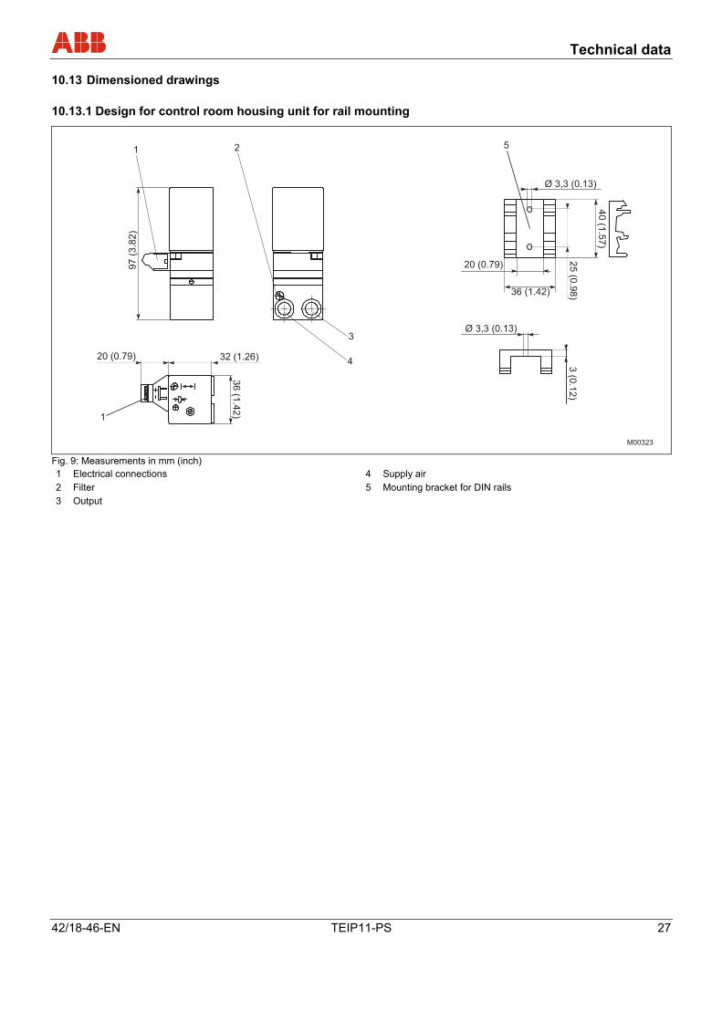
10.13.1 Design for control room housing unit for rail mounting
M00323
36
(1.4
2)
20 (0.79) 32 (1.26)
3(0
.12)
Ø 3,3 (0.13)
Ø 3,3 (0.13)
20 (0.79)
36 (1.42)
40
(1.5
7)
25
(0.9
8)
97
(3.8
2)
1
1
4
3
2 5
Fig. 9: Measurements in mm (inch) 1 Electrical connections 4 Supply air 2 Filter 5 Mounting bracket for DIN rails 3 Output
Pos: 25.3 /======= Seitenumbruch ======== @ 0\mod_1126532365768_3101.doc @ 3830
Technical data
28 TEIP11-PS 42/18-46-EN
Pos: 25.4 /Technische Daten / Datenblatt/Aktorik/I/P Signalumformer/TEIP11-PS/Maßzeichnungen/Bauform für Blockmontage @ 12\mod_1186663074375_3101.doc @ 113542
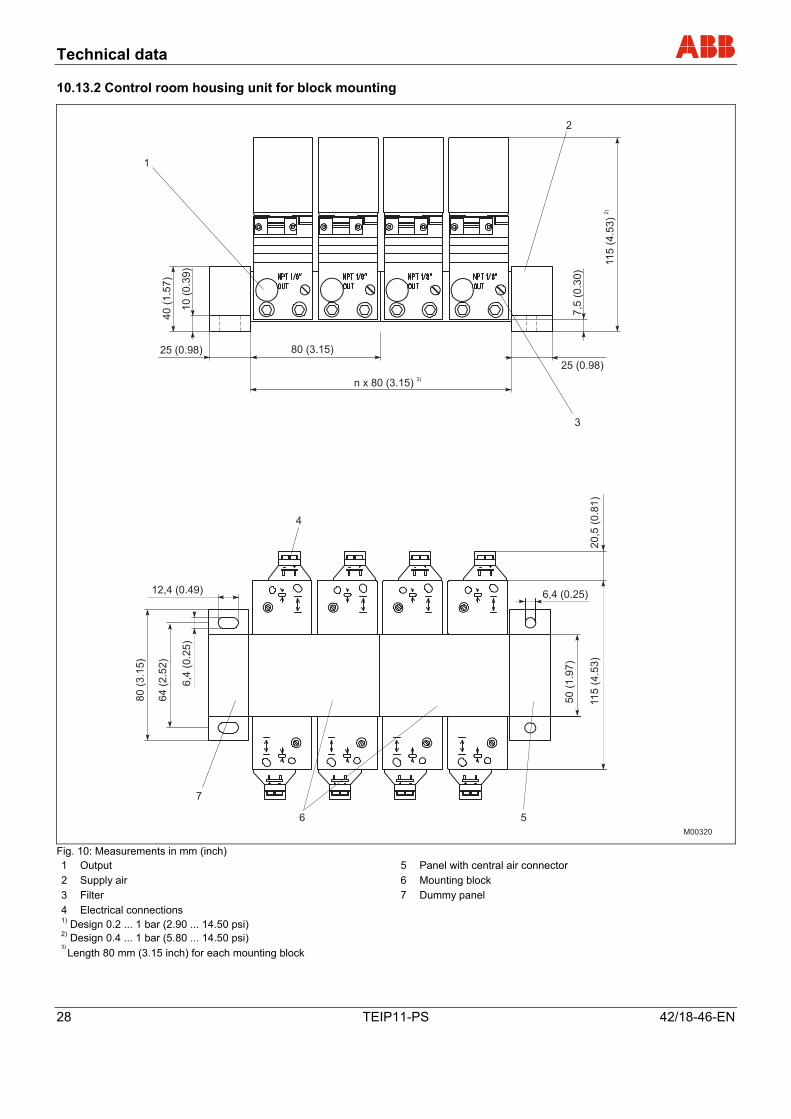
10.13.2 Control room housing unit for block mounting
M00320
12,4 (0.49)
n x 80 (3.15)3)
80 (3.15)
25 (0.98)
11
5(4
.53
)2
)
7,5
(0.3
0)
25 (0.98)
40
(1.5
7)
10
(0.3
9)
4
1
2
3
5
7
6
80
(3.1
5)
64
(2.5
2)
6,4
(0.2
5)
50
(1.9
7)
11
5(4
.53
)2
0,5
(0.8
1)
6,4 (0.25)
Fig. 10: Measurements in mm (inch) 1 Output 5 Panel with central air connector 2 Supply air 6 Mounting block 3 Filter 7 Dummy panel 4 Electrical connections 1) Design 0.2 ... 1 bar (2.90 ... 14.50 psi)
2) Design 0.4 ... 1 bar (5.80 ... 14.50 psi)
3) Length 80 mm (3.15 inch) for each mounting block
Pos: 25.5 /======= Seitenumbruch ======== @ 0\mod_1126532365768_3101.doc @ 3830
Technical data
42/18-46-EN TEIP11-PS 29
Pos: 25.6 /Technische Daten / Datenblatt/Aktorik/I/P Signalumformer/TEIP11-PS/Maßzeichnungen/Bauform Feldgehäuse (Kunststoff) @ 12\mod_1186665288125_3101.doc @ 113588
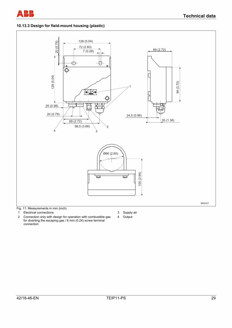
10.13.3 Design for field-mount housing (plastic)
Ø66 (2.60)
10
0(3
.94
)
94
(3.7
0)
69 (2.72)
35 (1.38)
24,5 (0.96)
128 (5.04)
12
8(5
.04
)
20
(0.7
9)
98,5 (3.88)
69 (2.72)
25 (0.98)
20 (0.79)
72 (2.83)
7 (0.28)
1
2
34
M00321 Fig. 11: Measurements in mm (inch) 1 Electrical connections 3 Supply air 2 Connection only with design for operation with combustible gas
for diverting the escaping gas / 6 mm (0.24) screw terminal connection
4 Output
Pos: 25.7 /======= Seitenumbruch ======== @ 0\mod_1126532365768_3101.doc @ 3830
Technical data
30 TEIP11-PS 42/18-46-EN
Pos: 25.8 /Technische Daten / Datenblatt/Aktorik/I/P Signalumformer/Allgemein/Maßzeichnungen/Bauform Feldmontage (Aluminium / Edelstahl) @ 12\mod_1186666498359_3101.doc @ 113681
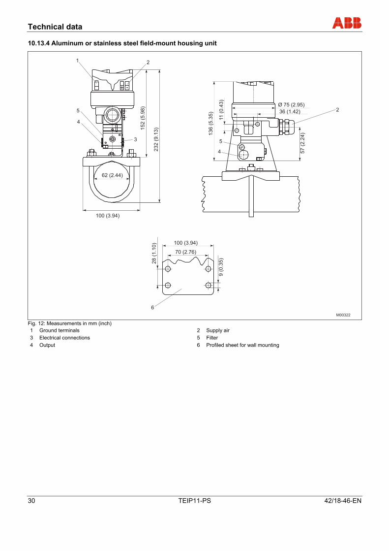
10.13.4 Aluminum or stainless steel field-mount housing unit
100 (3.94)
Ø 75 (2.95)
36 (1.42)
62 (2.44)
100 (3.94)
152
(5.9
8)
232
(9.1
3)
136
(5.3
5)
11
(0.4
3)
57
(2.2
4)
70 (2.76)
28
(1.1
0)
9(0
.35)
1 2
3
4
5
5
4
2
6
M00322 Fig. 12: Measurements in mm (inch) 1 Ground terminals 2 Supply air 3 Electrical connections 5 Filter 4 Output 6 Profiled sheet for wall mounting
Pos: 26 /======= Seitenumbruch ======== @ 0\mod_1126532365768_3101.doc @ 3830
Appendix
42/18-46-EN TEIP11-PS 31
Pos: 27.1 /Überschriften/1/A - C/Anhang @ 0\mod_1132904773022_3101.doc @ 3134
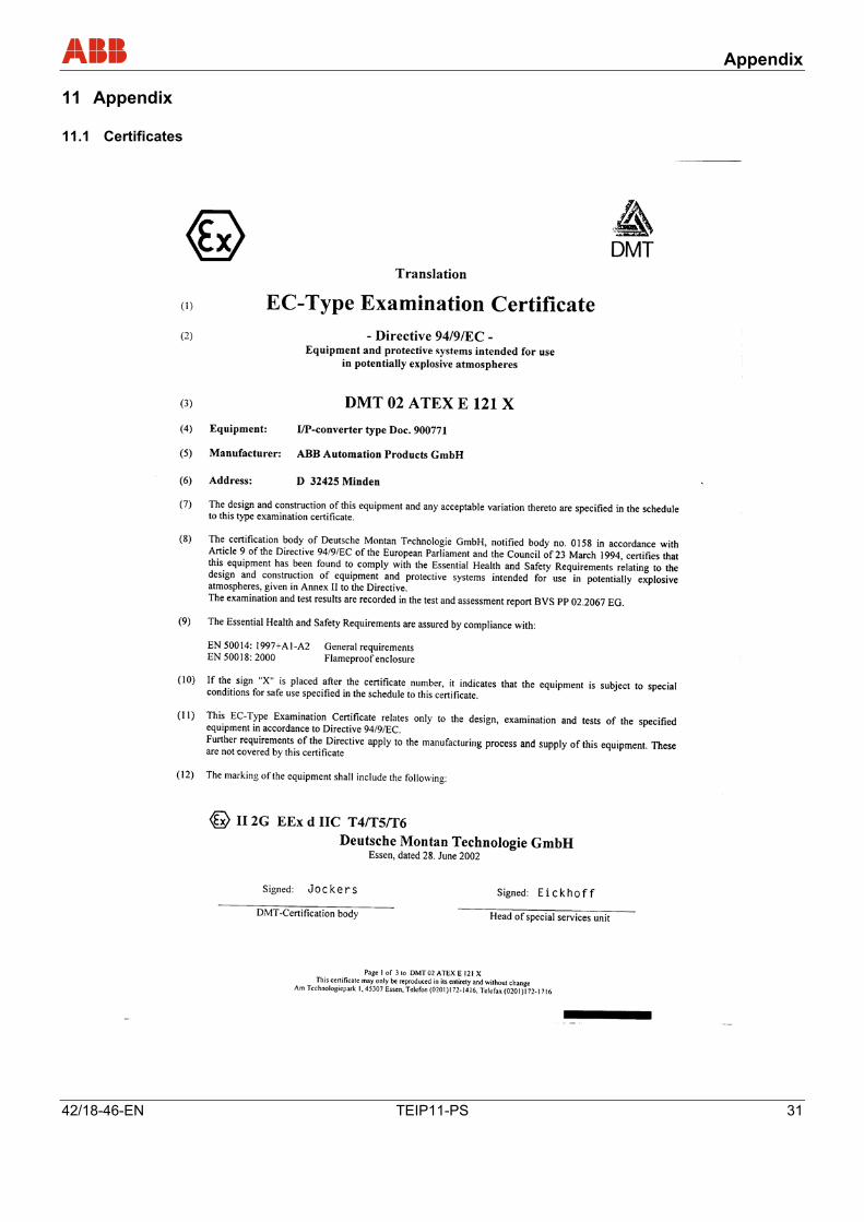
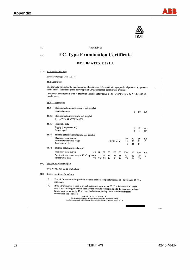
11 Appendix Pos: 27.2.1 /Überschriften/1.1/1-spaltig/V - Z/Zertifikate @ 12\mod_1190626989500_3101.doc @ 123416
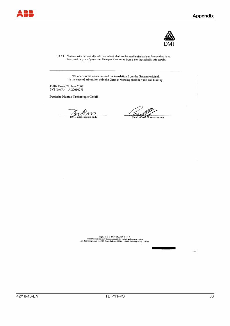
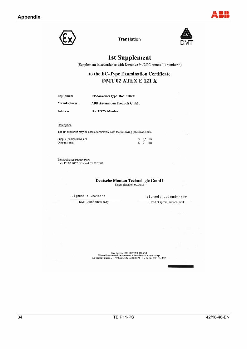
11.1 Certificates Pos: 27.2.2 /Anhang/Aktorik/I/P Signalumformer/TEIP11-PS/Zertifikate/Exd DMT 02 ATEX E121 X XA @ 12\mod_1190626140078_3101.doc @ 123370
Appendix
32 TEIP11-PS 42/18-46-EN
Appendix
42/18-46-EN TEIP11-PS 33
Appendix
34 TEIP11-PS 42/18-46-EN
Appendix
42/18-46-EN TEIP11-PS 35
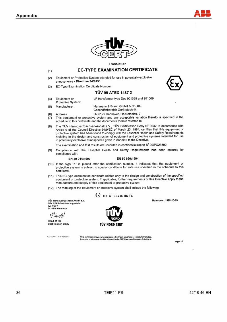
Pos: 27.2.3 /Anhang/Aktorik/I/P Signalumformer/TEIP11-PS/Zertifikate/ATEX 1487 X XA complete @ 12\mod_1190625873421_3101.doc @ 123347
Appendix
36 TEIP11-PS 42/18-46-EN
Appendix
42/18-46-EN TEIP11-PS 37
Appendix
38 TEIP11-PS 42/18-46-EN
Appendix
42/18-46-EN TEIP11-PS 39
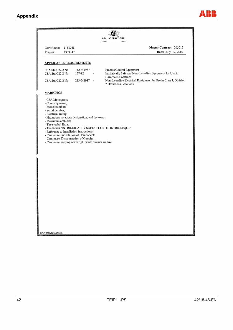
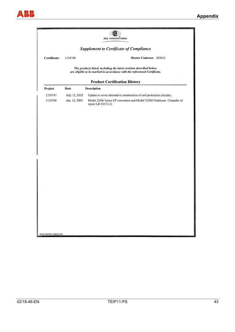
Pos: 27.2.4 /Anhang/Aktorik/I/P Signalumformer/TEIP11-PS/Zertifikate/CSA_Certificat @ 12\mod_1190625387750_3101.doc @ 123165
Appendix
40 TEIP11-PS 42/18-46-EN
Appendix
42/18-46-EN TEIP11-PS 41
Appendix
42 TEIP11-PS 42/18-46-EN
Appendix
42/18-46-EN TEIP11-PS 43
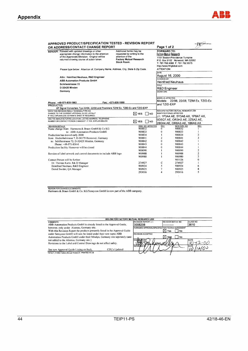
Pos: 27.2.5 /Anhang/Aktorik/I/P Signalumformer/TEIP11-PS/Zertifikate/FM-Report @ 12\mod_1190625582000_3101.doc @ 123278
Appendix
44 TEIP11-PS 42/18-46-EN
Appendix
42/18-46-EN TEIP11-PS 45
Pos: 27.2.6 /Anhang/Aktorik/I/P Signalumformer/TEIP11-PS/Zertifikate/GOST Russland @ 12\mod_1190625683375_3101.doc @ 123301
Pos: 27.2.7 /Anhang/Aktorik/I/P Signalumformer/TEIP11-PS/Zertifikate/GOST Ukraine @ 12\mod_1190625784093_3101.doc @ 123324
Pos: 27.3 /======= Seitenumbruch ======== @ 0\mod_1126532365768_3101.doc @ 3830
Appendix
46 TEIP11-PS 42/18-46-EN
Pos: 27.4 /Überschriften/1.1/1-spaltig/V - Z/Zulassungen und Zertifizierungen @ 0\mod_1132230068395_3101.doc @ 3806
11.2 Permits and certifications Pos: 27.5 /Anhang/Aktorik/I/P Signalumformer/TEIP11-PS/Zulassungen und Zertifizierungen (Ex) @ 12\mod_1186738056203_3101.doc @ 114849 Zu
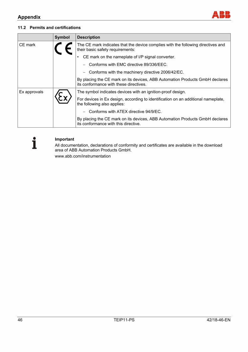
Symbol Description
CE mark
The CE mark indicates that the device complies with the following directives and their basic safety requirements:
• CE mark on the nameplate of I/P signal converter.
− Conforms with EMC directive 89/336/EEC.
− Conforms with the machinery directive 2006/42/EC.
By placing the CE mark on its devices, ABB Automation Products GmbH declares its conformance with these directives.
Ex approvals
The symbol indicates devices with an ignition-proof design.
For devices in Ex design, according to identification on an additional nameplate, the following also applies:
− Conforms with ATEX directive 94/9/EC.
By placing the CE mark on its devices, ABB Automation Products GmbH declares its conformance with this directive.
Pos: 27.6 /Anhang/Aktorik/Allgemein/Hinweis zum Download-Bereich (Aktorik) @ 10\mod_1182172251781_3101.doc @ 107696
Important All documentation, declarations of conformity and certificates are available in the download area of ABB Automation Products GmbH. www.abb.com/instrumentation
Pos: 27.7 /======= Seitenumbruch ======== @ 0\mod_1126532365768_3101.doc @ 3830
Appendix
42/18-46-EN TEIP11-PS 47
Pos: 27.8 /Anhang/Allgemein/Rücksendeformular @ 0\mod_1132757486454_3101.doc @ 3820
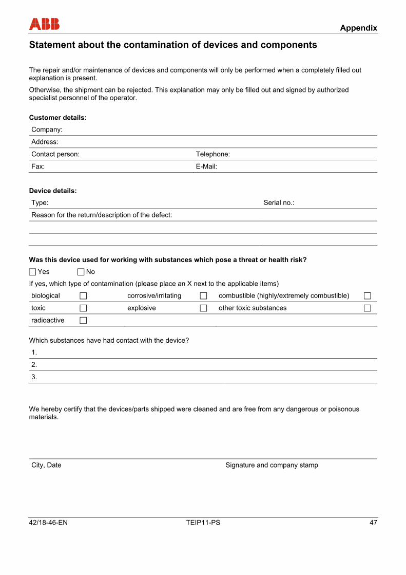
Statement about the contamination of devices and components
The repair and/or maintenance of devices and components will only be performed when a completely filled out explanation is present.
Otherwise, the shipment can be rejected. This explanation may only be filled out and signed by authorized specialist personnel of the operator.
Customer details:
Company:
Address:
Contact person: Telephone:
Fax: E-Mail:
Device details:
Type: Serial no.:
Reason for the return/description of the defect:
Was this device used for working with substances which pose a threat or health risk?
Yes No
If yes, which type of contamination (please place an X next to the applicable items)
biological corrosive/irritating combustible (highly/extremely combustible)
toxic explosive other toxic substances
radioactive
Which substances have had contact with the device?
1.
2.
3.
We hereby certify that the devices/parts shipped were cleaned and are free from any dangerous or poisonous materials.
City, Date Signature and company stamp
Pos: 28 /======= Seitenumbruch ======== @ 0\mod_1126532365768_3101.doc @ 3830
Index
48 TEIP11-PS 42/18-46-EN
Pos: 29 /Überschriften/1/G - I/Index @ 0\mod_1138787046328_3101.doc @ 3151
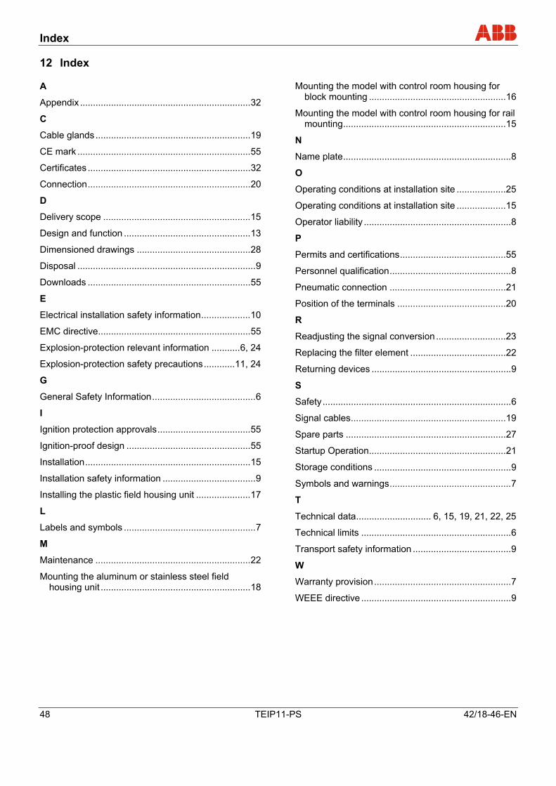
12 Index Pos: 30 /==== Wechsel ein- auf zweispaltig ==== @ 0\mod_1130421847171_3101.doc @ 3828 Wechsel ein-auf zweispaltig Pos: 31 /Inhaltsverzeichnis/Index @ 0\mod_1138784494500_3101.doc @ 3128
A
Appendix ..................................................................32
C
Cable glands............................................................19
CE mark ...................................................................55
Certificates ...............................................................32
Connection...............................................................20
D
Delivery scope .........................................................15
Design and function .................................................13
Dimensioned drawings ............................................28
Disposal .....................................................................9
Downloads ...............................................................55
E
Electrical installation safety information...................10
EMC directive...........................................................55
Explosion-protection relevant information ...........6, 24
Explosion-protection safety precautions............11, 24
G
General Safety Information........................................6
I
Ignition protection approvals....................................55
Ignition-proof design ................................................55
Installation................................................................15
Installation safety information ....................................9
Installing the plastic field housing unit .....................17
L
Labels and symbols ...................................................7
M
Maintenance ............................................................22
Mounting the aluminum or stainless steel field housing unit ..........................................................18
Mounting the model with control room housing for block mounting .....................................................16
Mounting the model with control room housing for rail mounting...............................................................15
N
Name plate.................................................................8
O
Operating conditions at installation site ...................25
Operating conditions at installation site ...................15
Operator liability .........................................................8
P
Permits and certifications.........................................55
Personnel qualification...............................................8
Pneumatic connection .............................................21
Position of the terminals ..........................................20
R
Readjusting the signal conversion ...........................23
Replacing the filter element .....................................22
Returning devices ......................................................9
S
Safety.........................................................................6
Signal cables............................................................19
Spare parts ..............................................................27
Startup Operation.....................................................21
Storage conditions .....................................................9
Symbols and warnings...............................................7
T
Technical data............................. 6, 15, 19, 21, 22, 25
Technical limits ..........................................................6
Transport safety information ......................................9
W
Warranty provision.....................................................7
WEEE directive ..........................................................9
Pos: 32 /==== Wechsel zwei- auf einspaltig ==== @ 0\mod_1130421955859_3101.doc @ 3829
Wechsel ein-auf zweispaltig Pos: 33 /Rückseiten/Minden_Aktorik @ 2\mod_1151575081640_3101.doc @ 32243 ===== Ende der Stückliste =====

ABB has Sales & Customer Support expertise in over 100 countries worldwide. www.abb.com/instrumentation
The Company’s policy is one of continuous productimprovement and the right is reserved to modify the
information contained herein without notice.
Printed in the Fed. Rep. of Germany (11.2007)
© ABB 2007
3KXE311001R4201
42/1
8-46
-EN
R
ev. G
ABB Limited Salterbeck Trading Estate Workington, Cumbria CA14 5DS UK Tel: +44 (0)1946 830 611 Fax: +44 (0)1946 832 661
ABB Inc. 125 E. County Line Road Warminster, PA 18974 USA Tel: +1 215 674 6000 Fax: +1 215 674 7183
ABB Automation Products GmbH Schillerstr. 72 32425 Minden Germany Tel: +49 551 905-534 Fax: +49 551 905-555 [email protected]