operating instructions liquistation csf34 products solutions services 71218001 valid as of:...
TRANSCRIPT

Products Solutions ServicesBA00482C/07/EN/021371218001
Valid as of:Softwareversion 01.04.00
Operating InstructionsLiquistation CSF34
Automatic sampler for liquid mediaOperation & settings

Operation concept
a0013353-en
Fig. 1: Pressing the soft key: selecting the menu directlya0013354-en
Fig. 2: Turning the navigator: moving the cursor in the menu
a0013355-en
Fig. 3: Pressing the navigator: launching a functiona0013356-en
Fig. 4: Turning the navigator: selecting a value (e.g. from a list)
a0013357-en
Fig. 5: Pressing the navigator: accepting the new valuea0013358-en
Fig. 6: Result: new setting is accepted
Liquistation CSF34
Table of contents
1 About this manual . . . . . . . . . . . 5
2 General settings . . . . . . . . . . . . . 62.1 Basic settings . . . . . . . . . . . . . . . . . . . . . . . 62.2 Date and time . . . . . . . . . . . . . . . . . . . . . . . 72.3 Automatic hold (optional) . . . . . . . . . . . . 82.4 Logbooks . . . . . . . . . . . . . . . . . . . . . . . . . . . 92.5 Configuring the sampling depending on
the device version . . . . . . . . . . . . . . . . . . 132.6 Extended setup . . . . . . . . . . . . . . . . . . . . 16
3 Inputs . . . . . . . . . . . . . . . . . . . . . 233.1 Binary inputs . . . . . . . . . . . . . . . . . . . . . . 233.2 Current inputs . . . . . . . . . . . . . . . . . . . . . 27
4 Programming . . . . . . . . . . . . . . 304.1 Overview of the possible program types 314.2 Program type: Basic . . . . . . . . . . . . . . . . . 354.3 Program types: Standard and Advanced 554.4 Selecting and executing the program . . 71
5 Outputs . . . . . . . . . . . . . . . . . . . 735.1 Binary outputs . . . . . . . . . . . . . . . . . . . . . 735.2 Current outputs (optional) . . . . . . . . . . . 765.3 Alarm relays . . . . . . . . . . . . . . . . . . . . . . . 785.4 HART . . . . . . . . . . . . . . . . . . . . . . . . . . . . . 815.5 PROFIBUS DP . . . . . . . . . . . . . . . . . . . . . . 815.6 Modbus RS485 and Modbus TCP . . . . . 82
6 Additional functions . . . . . . . . 836.1 Limit switch . . . . . . . . . . . . . . . . . . . . . . . 836.2 Cleaning programs . . . . . . . . . . . . . . . . . 876.3 Mathematical functions . . . . . . . . . . . . . 89
7 Communication . . . . . . . . . . . . 947.1 Web server . . . . . . . . . . . . . . . . . . . . . . . . 947.2 Service interface . . . . . . . . . . . . . . . . . . . . 967.3 Fieldbuses . . . . . . . . . . . . . . . . . . . . . . . . . 97
8 Information on sensors with the Memosens protocol . . . . . . . . . 98
9 Inputs: General . . . . . . . . . . . . . 999.1 Configuration . . . . . . . . . . . . . . . . . . . . . . 999.2 Frequently occurring functions . . . . . . . . 99
10 Inputs: pH/ORP Incl. combi sensors . . . . . . . . . . . . . . . . . . . 106
10.1 Basic settings . . . . . . . . . . . . . . . . . . . . . 10610.2 Extended setup . . . . . . . . . . . . . . . . . . . 107
11 Inputs: Conductivity . . . . . . . . 11511.1 Basic settings . . . . . . . . . . . . . . . . . . . . . 11511.2 Extended setup . . . . . . . . . . . . . . . . . . . 121
12 Inputs: Oxygen . . . . . . . . . . . . 12512.1 Basic settings . . . . . . . . . . . . . . . . . . . . . 12512.2 Extended setup . . . . . . . . . . . . . . . . . . . 126
13 Inputs: Chlorine . . . . . . . . . . . 13513.1 Basic settings . . . . . . . . . . . . . . . . . . . . . 13513.2 Extended setup . . . . . . . . . . . . . . . . . . . 136
14 Inputs: Turbidity and solids . 14314.1 Basic settings . . . . . . . . . . . . . . . . . . . . . 14314.2 Extended setup . . . . . . . . . . . . . . . . . . . 144
15 Inputs: SAC . . . . . . . . . . . . . . . 14815.1 Basic settings . . . . . . . . . . . . . . . . . . . . . 14815.2 Extended setup . . . . . . . . . . . . . . . . . . . 149
16 Inputs: Nitrate. . . . . . . . . . . . . 15316.1 Basic settings . . . . . . . . . . . . . . . . . . . . . 15316.2 Extended setup . . . . . . . . . . . . . . . . . . . 154
17 Inputs: ISE . . . . . . . . . . . . . . . . 15817.1 Basic settings . . . . . . . . . . . . . . . . . . . . . 15817.2 Extended setup . . . . . . . . . . . . . . . . . . . 15917.3 Electrode slot menus . . . . . . . . . . . . . . 16017.4 Limits operating hours . . . . . . . . . . . . . 167

Liquistation CSF34
4
18 Inputs: Interface. . . . . . . . . . . 16818.1 Basic settings . . . . . . . . . . . . . . . . . . . . . 16818.2 Manual hold . . . . . . . . . . . . . . . . . . . . . 16818.3 Tank configuration . . . . . . . . . . . . . . . . 16918.4 Sensor signal . . . . . . . . . . . . . . . . . . . . . 17018.5 Extended setup . . . . . . . . . . . . . . . . . . . 171
Index . . . . . . . . . . . . . . . . . . . . 174

Liquistation CSF34 About this manual
5
1 About this manualThis manual gives a detailed account of all the configuration options in the "Setup" menu.
A description of the following menus is provided here:• Inputs
– Input configuration– Split into separate sections based on the different types of sensor that can be connected
Some submenus are identical for all sensor types.These submenus are repeated in each input-specific section to make sure you can find the information you need quickly and easily.
• Outputs– Output configuration– Split into separate sections based on the different output types
• Sampling programs– Creating sampling programs– Configuring different types of programs
• Additional functions– Settings for the alarm sensor– Cleaning program configuration
• Data management– Firmware updates– Saving and loading configurations
This manual does not include the following:• Setup/General settings
--> Operating Instructions BA00478C "Commissioning"• Display/Operation
--> Operating Instructions BA00478C "Commissioning"• Calibration
--> Operating Instructions BA00484C "Calibration"• Diagnostics
--> Operating Instructions BA00483C "Maintenance & diagnostics"• Expert
--> Internal Service Manual

General settings Liquistation CSF34
6
2 General settingsMany settings are not visible when a program is running. If a program is running, stop the program before making any settings!
2.1 Basic settings
Path: Menu/Setup/General settings
Function Options Info
Device tag Customized text, 32 characters
Select any name for your controller. Use the TAG name for example.
Temperature unit Options• °C• °F• K
Factory setting°C
Current output range Options• 0 to 20 mA• 4 to 20 mA
Factory setting4 to 20 mA
In accordance with Namur NE43, the linear range is from 3.8 to 20.5 mA (Current output range="4 to 20 mA") or from 0 to 20.5 mA (Current output range="0 to 20 mA"). If the range is exceeded or undershot, the current value stops at the range limit and a diagnostics message (460 or 461) is output.You must select the "4 to 20 mA" range for HART communication.
Error current 0.0 to 23.0 mA
Factory setting21.5 mA
The function meets NAMUR NE43.Set the current value that should be output at the current outputs in the event of an error.
The value for "Error current" should be outside the measuring range. If you decided that your Current output range = "0 to 20 mA", you should set an error current between 20.1 and 23 mA. If the Current output range = "4 to 20 mA" you could also define a value < 4 mA as the error current.The device allows an error current within the measuring range. In such instances pay attention to possible affects this may have on your process.
Alarm delay 0 to 9999 s
Factory setting0 s
The system only displays the errors that are present longer than the set delay time. This makes it possible to suppress error messages that only occur briefly and are caused by normal process-specific fluctuations.

Liquistation CSF34 General settings
7
2.2 Date and time
Path: Menu/Setup/General settings/Date/Time
Function Options Info
Set date Depends on the format Editing mode:DD (day): 01 to 31MM (month): 01 to 12YYYY (year): 1970 to 2106
Set time Depends on the format Editing mode:hh (hour): 00 to 23 / 0 am to 12 pmmm (minutes): 00 to 59ss (seconds): 00 to 59
Extended setup
Date format Options• DD.MM.YYYY• YYYY-MM-DD• MM-DD-YYYY
Factory settingDD.MM.YYYY
Decide which date format you want to use.
Time format Options• HH:MM am (12h)• HH:MM (24h)• HH:MM:SS (24h)
Factory settingHH:MM:SS (24h)
Decide whether you want to use the 12-hour or 24-hour clock. Seconds can also be displayed with the latter version.
Time zone Options• None• Choice of 35 time zones
Factory settingNone
If no time zone is selected, then Greenwich Mean Time is used (London).
DST Options• Off• Europe• USA• Manual
Factory settingOff
The controller adapts the summertime/normal time changeover automatically if you choose European or American daylight saving time.Manual means that you can specify the start and end of daylight saving time yourself. Here, two additional submenus are displayed in which you specify the changeover date and time.
General settings Liquistation CSF34
8
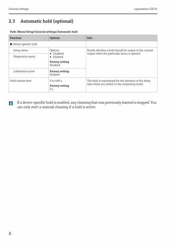
2.3 Automatic hold (optional)
If a device-specific hold is enabled, any cleaning that was previously started is stopped. You can only start a manual cleaning if a hold is active.
Path: Menu/Setup/General settings/Automatic hold
Function Options Info
Device specific hold
Setup menu Options• Disabled• Enabled
Factory settingDisabled
Decide whether a hold should be output at the current output when the particular menu is opened.
Diagnostics menu
Calibration active Factory settingEnabled
Hold release time 0 to 600 s
Factory setting0 s
The hold is maintained for the duration of the delay time when you switch to the measuring mode.
Liquistation CSF34 General settings
9
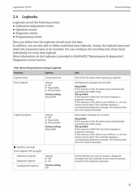
2.4 LogbooksLogbooks record the following events:• Calibration/adjustment events• Operation events• Diagnostic events• Programming events
Here you define how the logbooks should store the data.In addition, you are also able to define individual data logbooks. Assign the logbook name and select the measured value to be recorded. You can configure the recording rate (Scan time) individually for every data logbook.More information on the logbooks is provided in BA00483C "Maintenance & diagnostics", "Diagnostics menu" section.
Path: Menu/Setup/General settings/Logbooks
Function Options Info
Logbook ident Customized text Part of the file name when exporting a logbook
Event logbook Options• Off• Ring buffer• Fill up buffer
Factory settingRing buffer
All diagnostic messages are recorded
Ring bufferIf the memory is full, the latest entry automatically overwrites the oldest entry.Fill up bufferIf the memory is 80% full, the device displays a diagnostic message.If the memory is full, there is an overflow, i.e. no new values can be saved. The controller displays a corresponding diagnostic message. The memory then has to be cleared manually.
Logbook program Options• Off• Ring buffer• Fill up buffer
Factory settingRing buffer
All program messages are recorded
Ring bufferIf the memory is full, the latest entry automatically overwrites the oldest entry.Fill up bufferIf the memory is 80% full, the device displays a diagnostic message.If the memory is full, there is an overflow, i.e. no new values can be saved. The controller displays a corresponding diagnostic message. The memory then has to be cleared manually.
Overflow warnings
Event logbook="Fill up buffer"
Calibration logbook Options• Off• On
Factory settingOff
Decide whether you want to receive a diagnostic message from the controller in the event of memory overrun of the logbook in question.Diagnostic logbook
Configuration logbook
General settings Liquistation CSF34
10
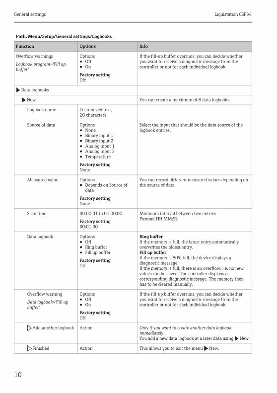
Overflow warnings
Logbook program="Fill up buffer"
Options• Off• On
Factory settingOff
If the fill-up buffer overruns, you can decide whether you want to receive a diagnostic message from the controller or not for each individual logbook.
Data logbooks
New You can create a maximum of 8 data logbooks.
Logbook name Customized text, 20 characters
Source of data Options• None• Binary input 1• Binary input 2• Analog input 1• Analog input 2• Temperature
Factory settingNone
Select the input that should be the data source of the logbook entries.
Measured value Options• Depends on Source of
data
Factory settingNone
You can record different measured values depending on the source of data.
Scan time 00:00:01 to 01:00:00
Factory setting00:01:00
Minimum interval between two entriesFormat: HH:MM:SS
Data logbook Options• Off• Ring buffer• Fill up buffer
Factory settingOff
Ring bufferIf the memory is full, the latest entry automatically overwrites the oldest entry.Fill up bufferIf the memory is 80% full, the device displays a diagnostic message.If the memory is full, there is an overflow, i.e. no new values can be saved. The controller displays a corresponding diagnostic message. The memory then has to be cleared manually.
Overflow warning
Data logbook="Fill up buffer"
Options• Off• On
Factory settingOff
If the fill-up buffer overruns, you can decide whether you want to receive a diagnostic message from the controller or not for each individual logbook.
Add another logbook Action Only if you want to create another data logbook immediately.You add a new data logbook at a later data using New.
Finished Action This allows you to exit the menu New.
Path: Menu/Setup/General settings/Logbooks
Function Options Info

Liquistation CSF34 General settings
11
Start/stop simultaneously
Action Appears if you have created more than one data logbook. With one click, you can start or stop recording for all the data logbooks.
"Logbook name" The name of this submenu is based on the name of the logbook and only appears once you have created a logbook.
This menu appears several times if you have several data logbooks.
Source of data Read only This is for information purposes only. If you want to record another value, delete this logbook and create a new data logbook.Measured value
Log time left
Data logbook="Fill up buffer"
Read only Displays the days, hours and minutes remaining until the logbook is full.
Log size
Data logbook="Ring buffer"
Read only Displays the number of entries remaining until the logbook is full.
Logbook name Customized text, 20 characters
You can change the name here again.
Scan time 00:00:01 to 01:00:00
Factory setting00:01:00
As aboveMinimum interval between two entriesFormat: HH:MM:SS
Data logbook Options• Off• Ring buffer• Fill up buffer
Factory settingOff
Ring bufferIf the memory is full, the latest entry automatically overwrites the oldest entry.Fill up bufferIf the memory is 80% full, the device displays a diagnostic message.If the memory is full, there is an overflow, i.e. no new values can be saved. The controller displays a corresponding diagnostic message. The memory then has to be cleared manually.
Line plotter Menu to define the graphic display
Axes Options• Off• On
Factory settingOn
Should the axes (x, y) be displayed (On) or not (Off)?
Orientation Options• Horizontal• Vertical
Factory settingHorizontal
You can choose whether the value curves should be displayed from left to right ("Horizontal") or from top to bottom ("Vertical").If you want to display two data logbooks simultaneously, make sure that both logbooks have the same settings here.
Path: Menu/Setup/General settings/Logbooks
Function Options Info

General settings Liquistation CSF34
12
Example for setting up a new data logbook1. Menu/Setup/General settings/Logbooks/Data logbooks/New:
a. Logbook name: Assign a name, e.g. "01".b. Source of data: Select a data source, e.g. the sensor connected to binary input 1.c. Measured value: Select the measured value that you want to record.d. Scan time: Specify the interval between two logbook entries.e. Data logbook: Activate the logbook. Specify the type of memory, "Ring buffer" or "Fill up
buffer".
2. ../Finished: Execute this action.--> Your new logbook now appears in the list of data logbooks.
3. Select the data logbook with the name "01".4. If you selected "Fill up buffer", you can also decide whether you want to receive a diagnostic
message in the event of memory overrun.5. Depending on the type of memory selected, you receive information about the memory
space (for "Ring buffer") or the time remaining until memory overrun (for "Fill up buffer").6. Define the graphic display mode in the "Line plotter" submenu.
X-Description Options• Off• On
Factory settingOn
Decide whether a description should be displayed for the axes and whether grids should be shown. In addition, you can also decide whether a pitch should be displayed.Y-Description
Grids
Pitches
X Pitch/Grid distance 10 to 50%
Factory setting10 %
Specify the pitch.
Y Pitch/Grid distance
Remove Action This action removes the data logbook. Any data that have not been saved are lost.
Path: Menu/Setup/General settings/Logbooks
Function Options Info

Liquistation CSF34 General settings
13
2.5 Configuring the sampling depending on the device versionThe list of functions displayed depends on the device version selected. Functions marked 1) are available in device versions with a vacuum pump. Functions marked 2) are available in device versions with a peristaltic pump. Functions marked 3) are available in device versions with a distribution arm drive.
Path: Menu/Setup/General settings
Function Options Info
Sampling
Number of bottles Choice of all possible bottle combinations
The bottle configuration you ordered is preset in the device.
Bottle volume 0 to 100000 ml
Factory settingDepends on the bottle configuration
Distribution reference 3) Options• Pre sampling• Pre bottle change• Pre program start
Factory settingPre sampling
The distribution arm goes through a reference point depending on the option selected.
Pre sampling:This means that the distribution arm performs a reference test before each individual sampling.
Pre bottle change:This means that the distribution arm performs a reference test in every subprogram.
Pre program start:This means that a single reference test is performed before the program starts.
Power failure Options• Resume program• Stop program
Factory settingResume program
Decide how the sampler should react when it is energized after a power failure.
Resume program:• Time and flow-paced
The program calculates the omitted samples and enters them in the logbook as failed. When the program is restarted, it continues where it was interrupted.
• Flow-pacedNo samples are entered in the logbook during the power failure. When the program is restarted, it continues where it was interrupted.
Sample retries 0 to 3
Factory setting0
If sampling is started and no sample is drawn in, sampling can be repeated up to 3 times.
Sampling delay 0 to 99 s
Factory setting0 s
The start of the sampling cycle can be delayed by up to 99 s. The binary output is switched without any delay.

General settings Liquistation CSF34
14
Liquid detection 1) Options• Automatic• Semi automatic
Factory settingAutomatic
If "Semiautomatic" is selected, the purge times and intake times can be defined separately.
Dosing volume 1) 1)20 to 350 ml
Factory setting200 ml
1)Adjust the dosing tube in the dosing chamber to change the dosing volume. The level in the bottle is calculated using the set dosing volume.
Conductive sensor 1) Options• Low sensitivity• Medium sensitivity• High sensitivity
Factory settingMedium sensitivity
The switching behavior can be set with the liquid detection function. Use the high sensitivity setting if the sample has a low conductivity, for example.
Dosing chamber 1) Options• Dose without pressure (A)• Dose with pressure (B)
Factory settingDose without pressure (A)
Dosing with pressure e.g. in conditions with low suction heights and slight counterpressure or low volumes.
Liquid detection 2) Options• Automatic• Semi automatic• Off
Factory settingAutomatic
If "Semiautomatic" is selected, the purge times and intake times can be defined separately.
Off:The definition of the purge times and intake times is completely time-controlled.Automatic:The last intake time determined is the new purge time.Semi automatic:If the suction heights tend to vary greatly.
Rinse cycles 2) 0 to 3
Factory setting0
The suction line is rinsed with the sample up to 3 times.
Safety interlock 2) (optional) Options• Off• On
Factory settingOff
If the peristaltic pump is opened, the safety interlock stops all the functions.
Diagnostics settings
Sensor fouling1)
Warning 0 to 10
Factory setting7
Indicates maintenance work must be performed on the conductivity sensors.If there is conductive fouling between the conductivity 1 and conductivity 2 electrode, a diagnostic message is displayed when this level of fouling is reached.
Path: Menu/Setup/General settings
Function Options Info

Liquistation CSF34 General settings
15
Alarm 7 to 10
Factory setting10
If there is conductive fouling between the conductivity 1 and conductivity 2 electrode, a diagnostic message is displayed when this level of fouling is reached.
Pump tube life 2)
Control Options• Off• On
Factory settingOn
Indicates the pump hose has to be exchanged.
Warning 10 to 50 h
Factory setting30 h
When the tube has been in operation for this length of time, a diagnostic message is displayed to indicate that the tube should be replaced in time.
Alarm 30 to 200 h
Factory setting50 h
Totalizer 00-00:00 to 49710-06:28
Factory setting00-00:00
Operating time of the current pump hose in days, hours and minutes
Reset Action The tube life counter is reset to 0:00 h.
Sample temperature (optional)
Temp. control Options• Off• On
Factory settingOn
Switch the temperature control of the sample compartment on or off here.
Economy operation Options• Off• On
Factory settingOff
On:Cooling is not enabled until the program takes the first sample. After this, the cooling regulator runs until the program is restarted.
Sample temperature 2 to 20 ˚C
Factory setting4 ˚C
Set the sample compartment temperature.
Cooling control Options• Standard operation• Quick cool down
Factory settingStandard operation
The temperature regulator is switched off for a certain time if quick cool-down is selected.
Path: Menu/Setup/General settings
Function Options Info

General settings Liquistation CSF34
16
2.6 Extended setup
2.6.1 Diagnostics settings
The list of diagnostic messages displayed depends on the path selected. There are device-specific messages, and messages that depend on what sensor is connected.
Path: ... /Extended setup/Diagnostics settings/Diag. behavior (optional)
Function Options Info
List of diagnostic messages Select the message to be changed. Only then can you make the settings for this message.
Diag. code Read only
Diagnostic message Options• On• Off
Factory settingDepends on the message
You can deactivate or reactivate a diagnostic message here.
Deactivating means:• No error message in the measuring mode• No error current at the current output
Error current Options• On• Off
Factory settingDepends on the message
Decide whether an error current should be output at the current output if the diagnostic message display is activated.
If general device errors occur, the error current is output at all the current outputs. In the case of channel-specific errors, the error current is only output at the specific current output.
Status signal Options• Maintenance (M)• Out of specification (S)• Function check (C)• Failure (F)
Factory settingDepends on the message
The messages are divided into different error categories in accordance with NAMUR NE 107.
Decide whether you want to change the status signal assignment for your application.
Diag. output Options• None• Alarm relay• Relay 1 to n (depends on
the device version)
Factory settingNone
You can use this function to select a relay output and/or binary output to which the diagnostic message should be assigned.
For sensors with the Memosens protocol:You first have to configure a relay output for "Diagnostics" (Menu/Setup/Outputs, assign "Diagnostics" function and set Operating mode to "as assigned") before being able to assign the message to an output.
Cleaning program (optional)
Options• None• Cleaning 1• Cleaning 2• Cleaning 3• Cleaning 4
Factory settingNone
Decide whether the diagnostic message should trigger a cleaning program.You can define the cleaning programs under:Menu/Setup/Additional functions/Cleaning.

Liquistation CSF34 General settings
17
2.6.2 HART bus address
If Multidrop is active (Bus address > 0), the current at current output 1 is fixed at 4 mA.Here, it does not matter what function has been assigned to the output (measured value/controller etc.). Current simulation is no longer possible.
If you reset the device to the factory settings (Diagnostics/Systemtest/Reset/Factory default), the bus address is not reset. Your setting is retained.
2.6.3 PROFIBUS DP
Detail information Read only Here you can find more information on the diagnostic message and instructions on how to resolve the problem.
Path: Menu/Setup/General settings/Extended setup/HART
Function Options Info
Bus address 0 to 63
Factory setting0
You can change the device address to integrate several HART devices in a network (Multidrop mode).
Path: Menu/Setup/General settings/Extended setup/PROFIBUS
Function Options Info
Enable Options• Off• On
Factory settingOff
You can switch off PROFIBUS communication at this point. The software can then only be accessed via local operation.
Termination Read only If the device is the last in the bus, you can terminate via the hardware.--> BA00478C, "Wiring" section
Bus address 1 to 125 If you have addressed the bus via hardware (DIP switches on the module, --> BA00478C), you can only read the address here.If an invalid address is set via the hardware, you have to assign a valid address for your device either here or via the bus.
Path: ... /Extended setup/Diagnostics settings/Diag. behavior (optional)
Function Options Info

General settings Liquistation CSF34
18
2.6.4 Modbus
Ident number Options• Automatic• PA-Profile 3.02 (9760)• Liquiline CM44x (155D)• Liquistation CSFxx
(155C)
Factory settingAutomatic
Path: Menu/Setup/General settings/Extended setup/Modbus
Function Options Info
Enable Options• Off• On
Factory settingOff
You can switch off Modbus communication at this point. The software can then only be accessed via local operation.
Termination Read only If the device is the last in the bus, you can terminate via the hardware.--> BA00478C, "Wiring" section
Settings
Transmission Mode Options• TCP• RTU• ASCII
The transmission mode is displayed depending on the version ordered. In the case of RS485 transmission, you can choose between "RTU" and "ASCII".
Watchdog 0 to 999 s
Factory setting5 s
If no data transmission takes place for longer than the time set, this is an indicator that communication has been interrupted.After this time, input values received via the Modbus are considered to be invalid.
Path: Menu/Setup/General settings/Extended setup/PROFIBUS
Function Options Info
Liquistation CSF34 General settings
19
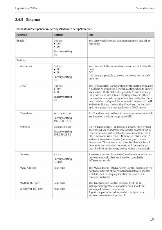
2.6.5 Ethernet
Path: Menu/Setup/General settings/Extended setup/Ethernet
Function Options Info
Enable Options• Off• On
Factory settingOn
You can switch ethernet communication on and off at this point.
Settings
Webserver Options• Off• On
Factory settingOn
You can switch the internal web server on and off at this point.Off:It is then not possible to access the device via the web browser.
DHCP Options• Off• On
Factory settingOff
The Dynamic Host Configuration Protocol (DHCP) makes it possible to assign the network configuration to clients via a server. With DHCP, it is possible to automatically integrate the device into an existing network without the need for manual configuration. Normally, the client need only be configured for automatic retrieval of the IP addresses. During startup, the IP address, the netmask and the gateway are retrieved from a DHCP server.
IP-Address xxx.xxx.xxx.xxx
Factory setting192.168.1.212
An IP address is an address in computer networks which are based on the Internet protocol (IP).
Netmask xxx.xxx.xxx.xxx
Factory setting255.255.255.0
On the basis of the IP address of a device, the netmask specifies which IP addresses this device searches for in its own network and which addresses it could access in other networks via a router. It therefore divides the IP address into a network part (network prefix) and a device part. The network part must be identical for all devices in the individual network, and the device part must be different for every device within the network.
Gateway x.x.x.x
Factory setting0.0.0.0
A gateway (protocol converter) enables communication between networks that are based on completely different protocols.
MAC-Address Read only The MAC address (Media Access Control address) is the hardware address of every individual network adapter which is used to uniquely identify the device in a computer network.
Modbus TCP port Read only The Transmission Control Protocol (TCP) is an arrangement (protocol) as to how data should be exchanged between computers.A port is a part of an address which assigns data segments to a network protocol.
Webserver TCP port Read only
General settings Liquistation CSF34
20
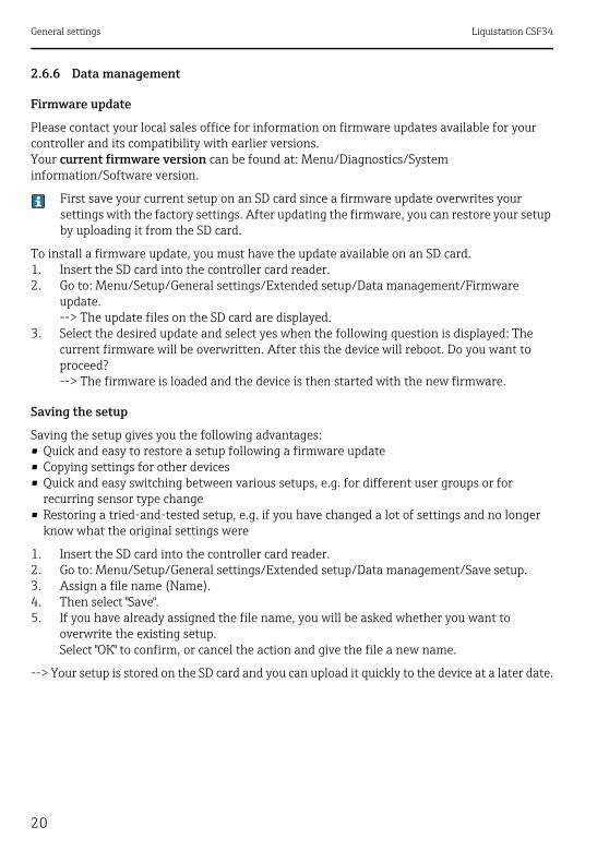
2.6.6 Data management
Firmware update
Please contact your local sales office for information on firmware updates available for your controller and its compatibility with earlier versions.Your current firmware version can be found at: Menu/Diagnostics/System information/Software version.
First save your current setup on an SD card since a firmware update overwrites your settings with the factory settings. After updating the firmware, you can restore your setup by uploading it from the SD card.
To install a firmware update, you must have the update available on an SD card.1. Insert the SD card into the controller card reader.2. Go to: Menu/Setup/General settings/Extended setup/Data management/Firmware
update.--> The update files on the SD card are displayed.
3. Select the desired update and select yes when the following question is displayed: The current firmware will be overwritten. After this the device will reboot. Do you want to proceed?--> The firmware is loaded and the device is then started with the new firmware.
Saving the setup
Saving the setup gives you the following advantages:• Quick and easy to restore a setup following a firmware update• Copying settings for other devices• Quick and easy switching between various setups, e.g. for different user groups or for
recurring sensor type change• Restoring a tried-and-tested setup, e.g. if you have changed a lot of settings and no longer
know what the original settings were
1. Insert the SD card into the controller card reader.2. Go to: Menu/Setup/General settings/Extended setup/Data management/Save setup.3. Assign a file name (Name).4. Then select "Save".5. If you have already assigned the file name, you will be asked whether you want to
overwrite the existing setup.Select "OK" to confirm, or cancel the action and give the file a new name.
--> Your setup is stored on the SD card and you can upload it quickly to the device at a later date.
Liquistation CSF34 General settings
21
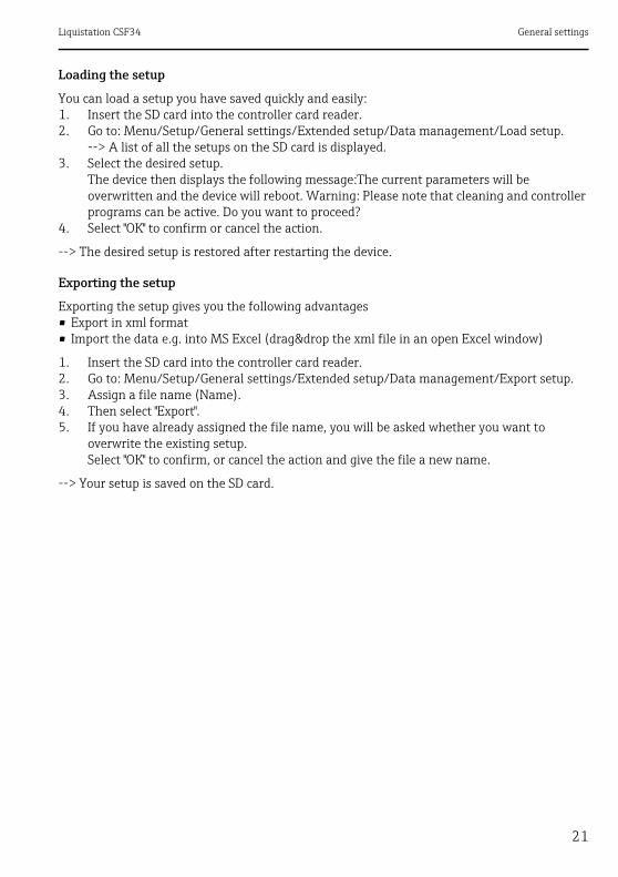
Loading the setup
You can load a setup you have saved quickly and easily:1. Insert the SD card into the controller card reader.2. Go to: Menu/Setup/General settings/Extended setup/Data management/Load setup.
--> A list of all the setups on the SD card is displayed.3. Select the desired setup.
The device then displays the following message:The current parameters will be overwritten and the device will reboot. Warning: Please note that cleaning and controller programs can be active. Do you want to proceed?
4. Select "OK" to confirm or cancel the action.
--> The desired setup is restored after restarting the device.
Exporting the setup
Exporting the setup gives you the following advantages• Export in xml format• Import the data e.g. into MS Excel (drag&drop the xml file in an open Excel window)
1. Insert the SD card into the controller card reader.2. Go to: Menu/Setup/General settings/Extended setup/Data management/Export setup.3. Assign a file name (Name).4. Then select "Export".5. If you have already assigned the file name, you will be asked whether you want to
overwrite the existing setup.Select "OK" to confirm, or cancel the action and give the file a new name.
--> Your setup is saved on the SD card.

General settings Liquistation CSF34
22
Activation code
You require activation codes for:• Additional functions, e.g. fieldbus communication• Software upgrades
Enter the activation code:‣ Menu/Setup/General settings/Extended setup/Data management/Activation code.‣ Confirm your entry. Your new hardware or software function is then activated and can be
configured.
If activation codes are available for your device, these codes are provided on the inner nameplate. The corresponding device functions are activated at the factory. You only require the codes if servicing the device.
The table below tells you what functions an activation code enables:Function Activation code beginning with
Second Memosens input 062...
Two current outputs (BASE-E module only) 081...
HART 0B1...
PROFIBUS DP 0B3...
Modbus TCP 0B4...
Modbus RS485 0B5...

Liquistation CSF34 Inputs
23
3 InputsLiquistation CSF34 has 2 binary inputs and 2 current inputs as standard. All inputs are galvanically isolated from one another.
3.1 Binary inputsThe binary inputs are used to control the sampler using external signals.With the CSF34, the auxiliary voltage of 24 V DC from the terminal block in the connection compartment of the sampler can be used for floating contacts (see BA00478C "Commissioning").
Path: Menu/Setup/Inputs
Function Options Info
Binary input S:x
Mode Options• Off• On
Factory settingOff
Switches the function on or off
Input mode Options• Flow rate• Rainfall• External event
Factory settingFlow rate
• Pulse input for connected flowmeters or rain gages• Control of sampling functions via external signals
If Input mode Flow rate is selected:
Signal slope Options• Low-High• High-Low
Factory settingLow-High
Preselect the level change of the signal.
Unit Options• m³• l• cf• gal
Factory settingm³
Select the unit.
Meas. value format Factory setting#.#
Specify the number of decimal places for the flow.
1 Impulse = 0 to 1000 m3
Factory setting10 m3
Definition of the pulse value, limits are calculated depending on the unit

Inputs Liquistation CSF34
24
Unit of totalized flow
Current totalized flow - - - The totalized flow values are displayed.
Reset totalizer Options• Manual• Automatic• At program start
Factory settingManual
Manual:Reset the counter manually.
Automatic:The counter is reset automatically at intervals.
At program start:The counter is reset at program start.
If counter reset Manual is selected:
Reset totalized flow Action The totalized flow currently calculated is set to zero when the counter is reset.
If counter reset Automatic is selected:
Interval Options• Daily• Weekly• Monthly
Factory settingDaily
Daily:If a daily interval is selected, set the Time in the menu item that follows.
Weekly:If a weekly interval is selected, set the Day of week and the Time in the menu items that follow.
Monthly:If a monthly interval is selected, set the Day of month and the Time in the menu items that follow.
Time 00:00:00 to 23:59:59 HH:MM:SS
Factory setting12:00:00 HH:MM:SS
If Input mode Rainfall is selected:
Signal slope Options• Low-High• High-Low
Factory settingLow-High
Preselect the level change of the signal.
Unit Options• mm• inch
Factory settingmm
Select the unit.
Meas. value format Factory setting#.#
Specify the number of decimal places.
1 Impulse = 0.00 to 5.00 mm
Factory setting1.0 mm
Definition of the pulse value, limits are calculated depending on the unit. The correct switch value is provided in the Operating Instructions of your rain gage.
Path: Menu/Setup/Inputs
Function Options Info
Liquistation CSF34 Inputs
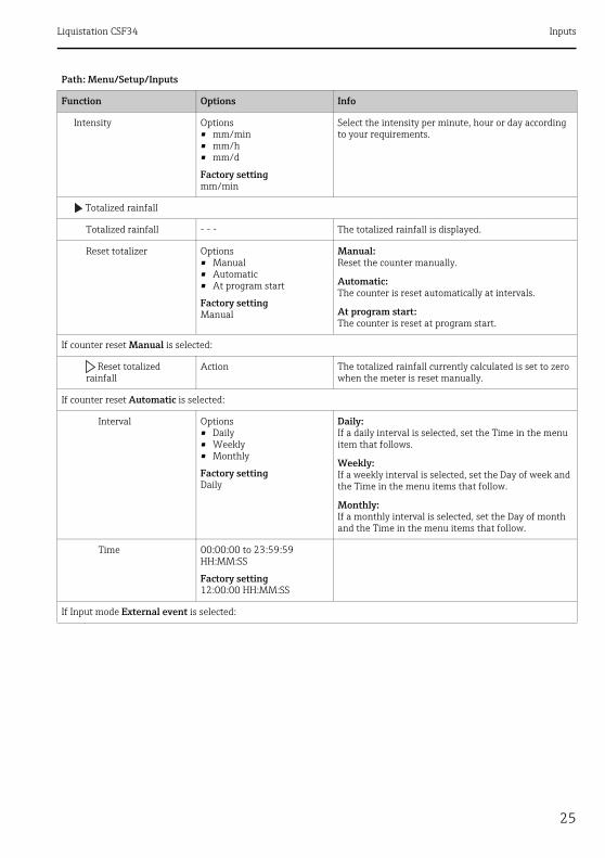
25
Intensity Options• mm/min• mm/h• mm/d
Factory settingmm/min
Select the intensity per minute, hour or day according to your requirements.
Totalized rainfall
Totalized rainfall - - - The totalized rainfall is displayed.
Reset totalizer Options• Manual• Automatic• At program start
Factory settingManual
Manual:Reset the counter manually.
Automatic:The counter is reset automatically at intervals.
At program start:The counter is reset at program start.
If counter reset Manual is selected:
Reset totalized rainfall
Action The totalized rainfall currently calculated is set to zero when the meter is reset manually.
If counter reset Automatic is selected:
Interval Options• Daily• Weekly• Monthly
Factory settingDaily
Daily:If a daily interval is selected, set the Time in the menu item that follows.
Weekly:If a weekly interval is selected, set the Day of week and the Time in the menu items that follow.
Monthly:If a monthly interval is selected, set the Day of month and the Time in the menu items that follow.
Time 00:00:00 to 23:59:59 HH:MM:SS
Factory setting12:00:00 HH:MM:SS
If Input mode External event is selected:
Path: Menu/Setup/Inputs
Function Options Info

Inputs Liquistation CSF34
26
Operation Options• No operation• Start sampling• Program start• Program stop• Program duration• Program pause• Partprogram activation• Change bottle• Bottle synchronization• External hold• Start cleaning
Factory settingNo operation
No operation:No action is executed.
Start sampling:A pulse triggers sampling.
Program start:A pulse starts a program.
Program stop:A pulse stops the program running.
Program duration:A program is active as long as the input signal is present.The signal is a level signal, i.e. the action takes effect as long as the level is present. The level that triggers the action is configured in the Signal slope menu item that follows.
Program pause:The input signal stops the program running. The programs continue running when the signal disappears.The signal is a level signal, i.e. the action takes effect as long as the level is present. The level that triggers the action is configured in the Signal slope menu item that follows.
Partprogram activation:A pulse triggers a subprogram.
Change bottle:A pulse triggers a changeover to the next bottle.
Bottle synchronization:A pulse triggers a changeover to the set bottle position.--> Then select the bottle position (depends on the bottle configuration).
External hold:The input signal triggers an external hold.The signal is a level signal, i.e. the action takes effect as long as the level is present. The level that triggers the action is configured in the Signal slope menu item that follows.
Start cleaning:A pulse triggers the cleaning.
Signal slope Options• Low-High• High-Low
Factory settingLow-High
Preselect the level change of the signal.--> If Low-High is selected, the high level brings about the corresponding setting.
Path: Menu/Setup/Inputs
Function Options Info

Liquistation CSF34 Inputs
27
3.2 Current inputsThe current input must be assigned an analog signal for the functions described. Active and passive current inputs are available to connect two-wire or four-wire devices.
For the correct wiring of the current inputs, see:BA00478C "Commissioning"
Path: Menu/Setup/Inputs
Function Options Info
Current input S:x
Mode Options• Off• 0 to 20 mA• 4 to 20 mA
Factory settingOff
Enter the output signal of the connected device: 0 to 20 mA or 4 to 20 mA.
Input mode Options• Flow rate• Parameter• Current
Factory settingCurrent
Select the input variable.
Flow rate:The input can be used as the source for time/flow-paced or flow-paced sampling programs.
Parameter:The input can be used as the source for limit switches, logbooks and enabling and disabling events for samp-ling programs.
Current:The input can be used as the source for limit switches, logbooks and enabling and disabling events for sampling programs.A unit name cannot be specified.
If Input mode Flow rate is selected:
Unit of flow Options• l/s• m³/s• m³/h• m3/d• cfs• cfm• gpm• gph• mgd
Factory settingl/s
Select the unit.
Unit of totalized flow Options• l• m³• cf• gal
Factory settingm³
Select the unit for the totalized flow.
Inputs Liquistation CSF34
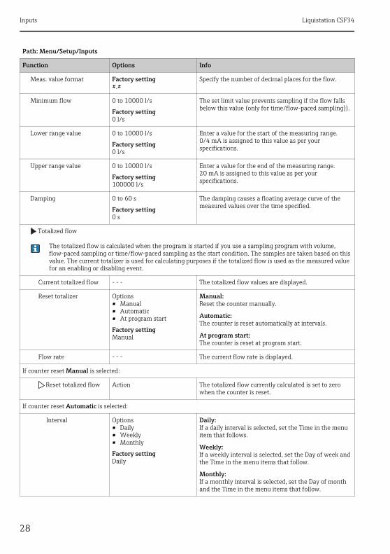
28
Meas. value format Factory setting#.#
Specify the number of decimal places for the flow.
Minimum flow 0 to 10000 l/s
Factory setting0 l/s
The set limit value prevents sampling if the flow falls below this value (only for time/flow-paced sampling)).
Lower range value 0 to 10000 l/s
Factory setting0 l/s
Enter a value for the start of the measuring range.0/4 mA is assigned to this value as per your specifications.
Upper range value 0 to 10000 l/s
Factory setting100000 l/s
Enter a value for the end of the measuring range.20 mA is assigned to this value as per your specifications.
Damping 0 to 60 s
Factory setting0 s
The damping causes a floating average curve of the measured values over the time specified.
Totalized flow
The totalized flow is calculated when the program is started if you use a sampling program with volume, flow-paced sampling or time/flow-paced sampling as the start condition. The samples are taken based on this value. The current totalizer is used for calculating purposes if the totalized flow is used as the measured value for an enabling or disabling event.
Current totalized flow - - - The totalized flow values are displayed.
Reset totalizer Options• Manual• Automatic• At program start
Factory settingManual
Manual:Reset the counter manually.
Automatic:The counter is reset automatically at intervals.
At program start:The counter is reset at program start.
Flow rate - - - The current flow rate is displayed.
If counter reset Manual is selected:
Reset totalized flow Action The totalized flow currently calculated is set to zero when the counter is reset.
If counter reset Automatic is selected:
Interval Options• Daily• Weekly• Monthly
Factory settingDaily
Daily:If a daily interval is selected, set the Time in the menu item that follows.
Weekly:If a weekly interval is selected, set the Day of week and the Time in the menu items that follow.
Monthly:If a monthly interval is selected, set the Day of month and the Time in the menu items that follow.
Path: Menu/Setup/Inputs
Function Options Info

Liquistation CSF34 Inputs
29
If Input mode Parameter is selected:
Meas. value format Factory setting#.#
Specify the number of decimal places.
Parameter name Customized text Assign a name.
Unit of measure Customized text Enter the engineering unit.
Lower range value -20 to 10000
Factory setting0
Enter a value for the start of the measuring range.0/4 mA is assigned to this value as per your specifications.
Upper range value -20 to 10000
Factory setting10
Enter a value for the end of the measuring range.20 mA is assigned to this value as per your specifications.
Damping 0 to 60 s
Factory setting0 s
The damping causes a floating average curve of the measured values over the time specified.
If Input mode Current is selected:
Meas. value format Factory setting#.#
Specify the number of decimal places.
Damping 0 to 60 s
Factory setting0 s
The damping causes a floating average curve of the measured values over the time specified.
Path: Menu/Setup/Inputs
Function Options Info
Programming Liquistation CSF34
30
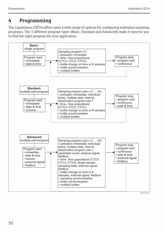
4 ProgrammingThe Liquistation CSF34 offers users a wide range of options for configuring individual sampling programs. The 3 different program types (Basic, Standard and Advanced) make it easy for you to find the right program for your application.
a0017981-en
Basic:
single programSampling program (1)
activation immediatetime-, flow proportional
(CTCV, VTCV, CTVV)bottle change on time or # samplesbottle synchronisationmultiple bottles
�
�
�
�
�
Program start:immediatedate & time�
�
Program stopprogram endcontinuous�
�
Standard:
multiple part-program Sampling program part n (1 ... 24)activation immediate, individual
times, multiple date, interval,deactivation program part 1
time-, flow proportional(CTCV, VTCV, CTVV)
bottle change on time or # samplesbottle synchronisationmultiple bottles
�
�
�
�
�
Program start:immediatedate & timevolume
�
�
�
Program stopprogram endcontinuousdate & time
�
�
�
Advanced:
multiple part-program Sampling program part n (1 ... 24)activation immediate, individual
times, multiple date, interval,deactivation program part 1,parameter event, external signal,fieldbus
time-, flow proportional (CTCV,VTCV, CTVV), single sample,sampling table, external signal,fieldbus
bottle change on time or #samples, external signal, fieldbus
sampling synchronisationbottle synchronisationmultiple bottles
�
�
�
�
�
�
Program start:immediatedate & timevolumeexternal signalfieldbus
�
�
�
�
�
Program stopprogram endcontinuousdate & timeexternal signalfieldbus
�
�
�
�
�

Liquistation CSF34 Programming
31
4.1 Overview of the possible program types
The graphic below explains the various ways sampling can be controlled on the basis of a flow curve:
Sampling mode Basic program type Standard program type Advanced program type
Time-paced Time-paced Time-paced
Flow-paced Flow-paced Flow-paced
Vacuum/peristaltic pump Single sample
Sampling table
External signal
Fieldbus (optional)
Peristaltic pump Time/flow-paced Time/flow-paced Time/flow-paced
a0014045
Fig. 7: Sampling control
a. Flow curveb. Time-paced sampling
A constant sampling volume (e.g. 50 ml) is taken at steady intervals (e.g. every 5 min).
c. Flow-paced samplingA constant sampling volume is taken at variable intervals (depending on the inflow volume).
d. Time/flow-paced samplingA variable sampling volume (the sampling volume depends on the inflow) is taken at steady time intervals (e.g. every 10 min).
e. Event-controlled samplingSampling is triggered by an event (e.g. pH limit value). Sampling can be time-paced, flow-paced, or time/flow-paced, or single samples can be taken.
Programming Liquistation CSF34
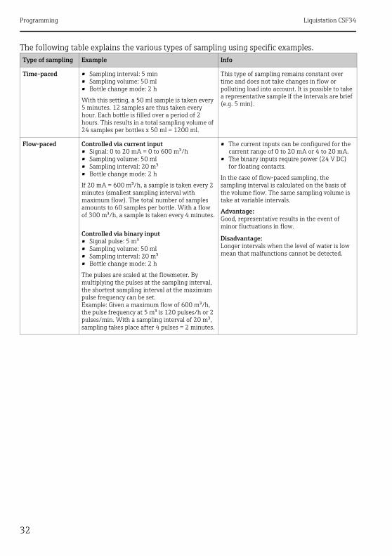
32
The following table explains the various types of sampling using specific examples.Type of sampling Example Info
Time-paced • Sampling interval: 5 min• Sampling volume: 50 ml• Bottle change mode: 2 h
With this setting, a 50 ml sample is taken every 5 minutes. 12 samples are thus taken every hour. Each bottle is filled over a period of 2 hours. This results in a total sampling volume of 24 samples per bottles x 50 ml = 1200 ml.
This type of sampling remains constant over time and does not take changes in flow or polluting load into account. It is possible to take a representative sample if the intervals are brief (e.g. 5 min).
Flow-paced Controlled via current input• Signal: 0 to 20 mA = 0 to 600 m³/h• Sampling volume: 50 ml• Sampling interval: 20 m³• Bottle change mode: 2 h
If 20 mA = 600 m³/h, a sample is taken every 2 minutes (smallest sampling interval with maximum flow). The total number of samples amounts to 60 samples per bottle. With a flow of 300 m³/h, a sample is taken every 4 minutes.
Controlled via binary input• Signal pulse: 5 m³• Sampling volume: 50 ml• Sampling interval: 20 m³• Bottle change mode: 2 h
The pulses are scaled at the flowmeter. By multiplying the pulses at the sampling interval, the shortest sampling interval at the maximum pulse frequency can be set.Example: Given a maximum flow of 600 m³/h, the pulse frequency at 5 m³ is 120 pulses/h or 2 pulses/min. With a sampling interval of 20 m³, sampling takes place after 4 pulses = 2 minutes.
• The current inputs can be configured for the current range of 0 to 20 mA or 4 to 20 mA.
• The binary inputs require power (24 V DC) for floating contacts.
In the case of flow-paced sampling, the sampling interval is calculated on the basis of the volume flow. The same sampling volume is take at variable intervals.
Advantage:Good, representative results in the event of minor fluctuations in flow.
Disadvantage:Longer intervals when the level of water is low mean that malfunctions cannot be detected.
Liquistation CSF34 Programming
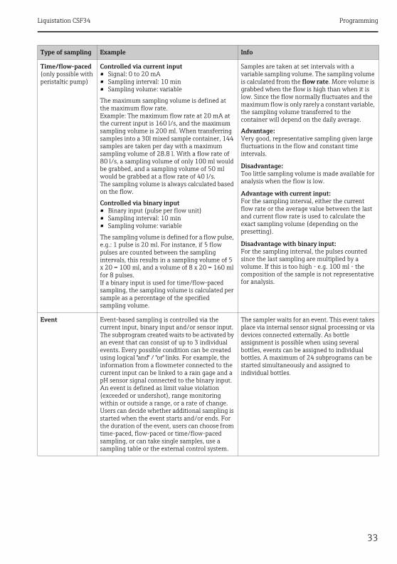
33
Time/flow-paced (only possible with peristaltic pump)
Controlled via current input• Signal: 0 to 20 mA• Sampling interval: 10 min• Sampling volume: variable
The maximum sampling volume is defined at the maximum flow rate. Example: The maximum flow rate at 20 mA at the current input is 160 l/s, and the maximum sampling volume is 200 ml. When transferring samples into a 30l mixed sample container, 144 samples are taken per day with a maximum sampling volume of 28.8 l. With a flow rate of 80 l/s, a sampling volume of only 100 ml would be grabbed, and a sampling volume of 50 ml would be grabbed at a flow rate of 40 l/s.The sampling volume is always calculated based on the flow.
Controlled via binary input• Binary input (pulse per flow unit)• Sampling interval: 10 min• Sampling volume: variable
The sampling volume is defined for a flow pulse, e.g.: 1 pulse is 20 ml. For instance, if 5 flow pulses are counted between the sampling intervals, this results in a sampling volume of 5 x 20 = 100 ml, and a volume of 8 x 20 = 160 ml for 8 pulses. If a binary input is used for time/flow-paced sampling, the sampling volume is calculated per sample as a percentage of the specified sampling volume.
Samples are taken at set intervals with a variable sampling volume. The sampling volume is calculated from the flow rate. More volume is grabbed when the flow is high than when it is low. Since the flow normally fluctuates and the maximum flow is only rarely a constant variable, the sampling volume transferred to the container will depend on the daily average.
Advantage:Very good, representative sampling given large fluctuations in the flow and constant time intervals.
Disadvantage:Too little sampling volume is made available for analysis when the flow is low.
Advantage with current input:For the sampling interval, either the current flow rate or the average value between the last and current flow rate is used to calculate the exact sampling volume (depending on the presetting).
Disadvantage with binary input:For the sampling interval, the pulses counted since the last sampling are multiplied by a volume. If this is too high - e.g. 100 ml - the composition of the sample is not representative for analysis.
Event Event-based sampling is controlled via the current input, binary input and/or sensor input. The subprogram created waits to be activated by an event that can consist of up to 3 individual events. Every possible condition can be created using logical "and" / "or" links. For example, the information from a flowmeter connected to the current input can be linked to a rain gage and a pH sensor signal connected to the binary input. An event is defined as limit value violation (exceeded or undershot), range monitoring within or outside a range, or a rate of change. Users can decide whether additional sampling is started when the event starts and/or ends. For the duration of the event, users can choose from time-paced, flow-paced or time/flow-paced sampling, or can take single samples, use a sampling table or the external control system.
The sampler waits for an event. This event takes place via internal sensor signal processing or via devices connected externally. As bottle assignment is possible when using several bottles, events can be assigned to individual bottles. A maximum of 24 subprograms can be started simultaneously and assigned to individual bottles.
Type of sampling Example Info

Programming Liquistation CSF34
34
4.1.1 Bottle synchronization
The bottle synchronization setting is possible with all types of program. In addition, bottle synchronization can be switched via an external signal.Bottle synchronization is only possible with a bottle change after a specific time and not with a bottle change after a number of samples.
Specific bottles can be assigned specific filling times with the bottle synchronization function. For example, bottle 1 is to be filled from midnight to 2 a.m., bottle 2 from 2 a.m. to 4 a.m. etc.. The following options are available for this:
• None: The time of sampling and bottle change are not synchronized.• 1. bottle change time: Sampling starts with the first bottle. The changeover to the next bottles
is synchronized. For example, a time of 2 hours was set for bottle changeover, and 00:00 was set for the synchronization. If the program is started at 5:23 a.m., for example, bottle 1 is initially filled. The system switches for the first time to bottle 2 at midnight (00:00), to bottle 3 at 2 a.m. etc.
• 1. Time of change + bottle number: A specific filling time is assigned to every bottle. For example, midnight to 2 a.m. for bottle 1; 2 a.m. to 4 a.m. for bottle 2; 4 a.m. to 6 a.m. for bottle 3 etc. If the program is started at 10 a.m., for example, the device starts filling bottle 6.It is also possible to start synchronization on a specific day of the week. For example, a time of 24 hours was set for bottle changeover, Monday 00:00 was the time set for synchronization, and Tuesday 8 a.m. was set for starting the program. The system fills bottle 2 until 00:00 on Wednesday and then switches to bottle 3.
• External signal: The system changes to the next bottle when an external signal is received. The external signal first has to be configured via the binary input. The binary input can then be selected as the source.

Liquistation CSF34 Programming
35
4.2 Program type: BasicWith the Basic program type, you can create simple sampling programs quickly based on time, volume and flow. In the case of volume- and flow-controlled sampling, the inputs have to be configured appropriately beforehand. If you want to create a program and use it immediately, you have to check the configuration of the sampler before programming. You can make the settings under "Menu/Setup/General settings/Sampling": e.g. the bottle configuration, and the bottle volume, as well as the correct dosing volume for the device version with a vacuum pump. The dosing volume setting makes it possible to correctly calculate the level in the bottle and is a reliable way of preventing the bottles from being overfilled.
You can go to the Setup program either via the overview under "Select sampling program" or via the path "Menu/Setup/Sampling programs".
Path: Menu/Setup/Sampling programs
Function Options Info
Current program: Read only The last sampling program to be created or used is displayed.
Status Read only Display "Active":The sampling program has been started and the device takes a sample as per the set parameters.Display "Inactive":No sampling program has been started, or a program that was running has been paused.Display "Pause":Sampling program paused.
Setup program
New A list of all the programs created is displayed. For this reason, it is often helpful to add a "B" for Basic in the program name.
Program1, which is supplied with the device, is displayed, as is a list of all the programs already created (Basic, Standard or Advanced programs). You can either create a new program or select an existing one. If you select an existing program, you can edit, delete, start or duplicate it. Furthermore, you can also see whether this program is a Basic, Standard or Advanced program.If you are creating a new program, select the Basic, Standard or Advanced program type.
Basic
Program name Customized text Use a distinct name for your sampling program. The program name can be up to 16 characters long.
Bottle configuration Choice of all possible bottle combinations
The ordered bottle configuration is preset or the configuration selected in the setup is displayed.

Programming Liquistation CSF34
36
Options:- 1x - PE direct distribution- 2x - PE direct distribution- 4x - PE direct distribution- 4x - glass direct distribution- 12x - PE direct distribution- 24x - PE direct distribution- 12x+6x PE direct distribution
Bottle volume 0 to 100000 ml
Factory setting30000 ml
Set the bottle volume.The preset value depends on the bottle configuration configured. The bottle volume is always 30 l for individual containers.
Sampling mode Options• Time paced CTCV• Flow paced VTCV• Time/flow paced CTVV• External signal
Factory settingTime paced CTCV
The following functions depend on the option selected.These versions are illustrated individually in the following section to provide a clearer understanding of the options.
Time paced CTCV:A constant sampling volume is taken at steady intervals.
Flow paced VTCV:A constant sampling volume is taken at variable intervals.
Time/flow paced CTVV (only for version with peristaltic pump):A variable sampling volume is taken at steady intervals.
Path: Menu/Setup/Sampling programs
Function Options Info
Liquistation CSF34 Programming
37
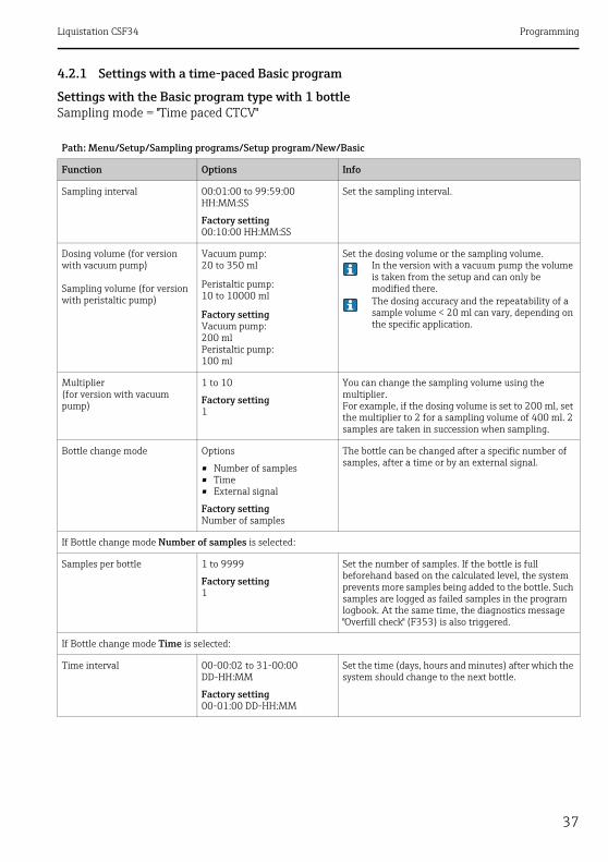
4.2.1 Settings with a time-paced Basic program
Settings with the Basic program type with 1 bottleSampling mode = "Time paced CTCV"
Path: Menu/Setup/Sampling programs/Setup program/New/Basic
Function Options Info
Sampling interval 00:01:00 to 99:59:00 HH:MM:SS
Factory setting00:10:00 HH:MM:SS
Set the sampling interval.
Dosing volume (for version with vacuum pump)
Sampling volume (for version with peristaltic pump)
Vacuum pump:20 to 350 ml
Peristaltic pump:10 to 10000 ml
Factory settingVacuum pump:200 mlPeristaltic pump:100 ml
Set the dosing volume or the sampling volume.In the version with a vacuum pump the volume is taken from the setup and can only be modified there.The dosing accuracy and the repeatability of a sample volume < 20 ml can vary, depending on the specific application.
Multiplier(for version with vacuum pump)
1 to 10
Factory setting1
You can change the sampling volume using the multiplier. For example, if the dosing volume is set to 200 ml, set the multiplier to 2 for a sampling volume of 400 ml. 2 samples are taken in succession when sampling.
Bottle change mode Options
• Number of samples• Time• External signal
Factory settingNumber of samples
The bottle can be changed after a specific number of samples, after a time or by an external signal.
If Bottle change mode Number of samples is selected:
Samples per bottle 1 to 9999
Factory setting1
Set the number of samples. If the bottle is full beforehand based on the calculated level, the system prevents more samples being added to the bottle. Such samples are logged as failed samples in the program logbook. At the same time, the diagnostics message "Overfill check" (F353) is also triggered.
If Bottle change mode Time is selected:
Time interval 00-00:02 to 31-00:00 DD-HH:MM
Factory setting00-01:00 DD-HH:MM
Set the time (days, hours and minutes) after which the system should change to the next bottle.
Programming Liquistation CSF34
38
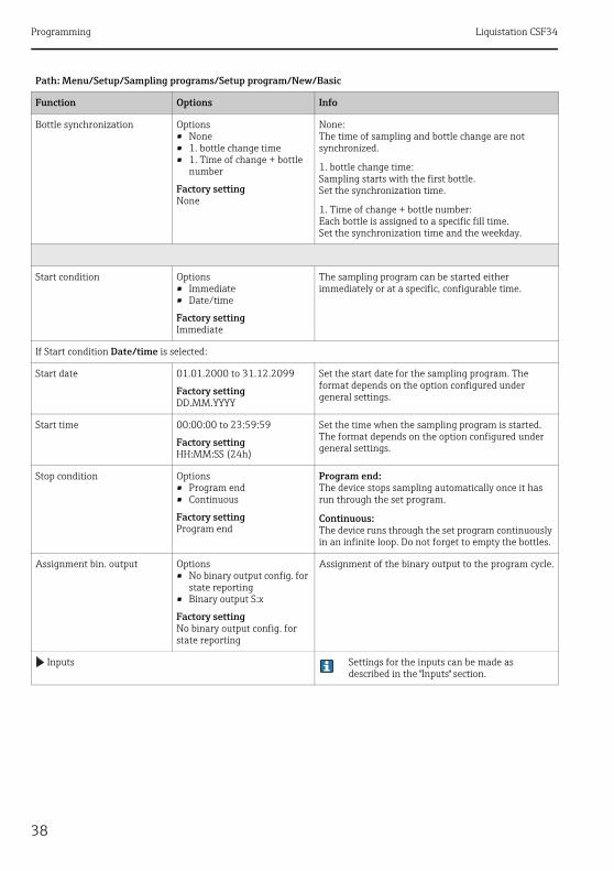
Bottle synchronization Options• None• 1. bottle change time• 1. Time of change + bottle
number
Factory settingNone
None:The time of sampling and bottle change are not synchronized.
1. bottle change time:Sampling starts with the first bottle.Set the synchronization time.
1. Time of change + bottle number:Each bottle is assigned to a specific fill time.Set the synchronization time and the weekday.
Start condition Options• Immediate• Date/time
Factory settingImmediate
The sampling program can be started either immediately or at a specific, configurable time.
If Start condition Date/time is selected:
Start date 01.01.2000 to 31.12.2099
Factory settingDD.MM.YYYY
Set the start date for the sampling program. The format depends on the option configured under general settings.
Start time 00:00:00 to 23:59:59
Factory settingHH:MM:SS (24h)
Set the time when the sampling program is started. The format depends on the option configured under general settings.
Stop condition Options• Program end• Continuous
Factory settingProgram end
Program end:The device stops sampling automatically once it has run through the set program.
Continuous:The device runs through the set program continuously in an infinite loop. Do not forget to empty the bottles.
Assignment bin. output Options• No binary output config. for
state reporting• Binary output S:x
Factory settingNo binary output config. for state reporting
Assignment of the binary output to the program cycle.
Inputs Settings for the inputs can be made as described in the "Inputs" section.
Path: Menu/Setup/Sampling programs/Setup program/New/Basic
Function Options Info

Liquistation CSF34 Programming
39
Settings with the Basic program type with multiple bottlesSampling mode = "Time paced CTCV"
Path: Menu/Setup/Sampling programs/Setup program/New/Basic
Function Options Info
Sampling interval 00:01:00 to 99:59:00 HH:MM:SS
Factory setting00:10:00 HH:MM:SS
Set the sampling interval.
Dosing volume (for version with vacuum pump)
Sampling volume (for version with peristaltic pump)
Vacuum pump:20 to 350 ml
Peristaltic pump:10 to 10000 ml
Factory settingVacuum pump:200 mlPeristaltic pump:100 ml
Set the dosing volume or the sampling volume.The volume is taken from the setup in the version with a vacuum pump.
The dosing accuracy and the repeatability of a sample volume < 20 ml can vary, depending on the specific application.
Multiplier(only for version with vacuum pump)
1 to 10
Factory setting1
You can change the sampling volume using the multiplier. For example, if the dosing volume is set to 200 ml, set the multiplier to 2 for a sampling volume of 400 ml. 2 samples are taken in succession when sampling.
Bottle change mode Options• Number of samples• Time• External signal
Factory settingNumber of samples
The bottle can be changed after a specific number of samples, after a time or by an external signal.
If Bottle change mode Number of samples is selected:
Samples per bottle 1 to 9999
Factory setting1
Set the number of samples.If the bottle is full beforehand based on the calculated level, the system prevents more samples being added to the bottle. Such samples are logged as failed samples in the program logbook.
If Bottle change mode Time is selected:
Time interval 00-00:02 to 31-00:00 DD-HH:MM
Factory setting00-01:00 DD-HH:MM
Set the time (days, hours and minutes) after which the system should change to the next bottle.
Multiple bottles 0 to 23The configuration options depend on the current number of bottles
Factory setting0
Multiple bottles:"Simultaneous" transfer of two samples to separate bottles.

Programming Liquistation CSF34
40
Bottle synchronization Options• None• 1. bottle change time• 1. Time of change + bottle
number
Factory settingNone
None:The time of sampling and bottle change are not synchronized.
1. bottle change time:Sampling starts with the first bottle.Set the synchronization time.
1. Time of change + bottle number:Each bottle is assigned to a specific fill time.Set the synchronization time and the weekday.
If Bottle change mode External signal is selected:
Bottle change signal input Options• No bottle change input
configured• Binary input S:x
Factory settingNo bottle change input configured
The bottle change input can be configured under Inputs .
Multiple bottles 0 to 23The configuration options depend on the current number of bottles
Factory setting0
Multiple bottles:"Simultaneous" transfer of two samples to separate bottles.
Start condition Options• Immediate• Date/time
Factory settingImmediate
The sampling program can be started either immediately or at a specific, configurable time.
If Start condition Date/time is selected:
Start date 01.01.2000 to 31.12.2099
Factory settingDD.MM.YYYY
Set the start date for the sampling program. The format depends on the option configured under general settings.
Start time 00:00:00 to 23:59:59
Factory settingHH:MM:SS (24h)
Set the time when the sampling program is started. The format depends on the option configured under general settings.
Path: Menu/Setup/Sampling programs/Setup program/New/Basic
Function Options Info
Liquistation CSF34 Programming
41
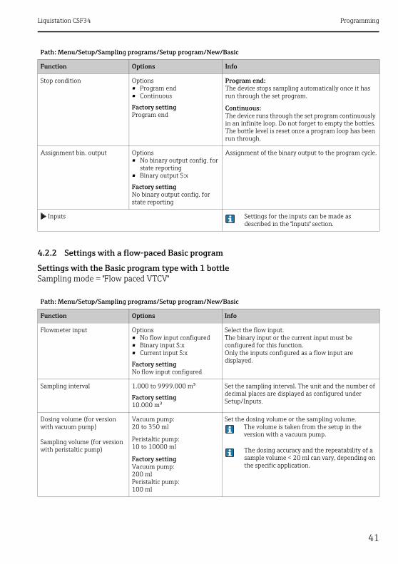
4.2.2 Settings with a flow-paced Basic program
Settings with the Basic program type with 1 bottleSampling mode = "Flow paced VTCV"
Stop condition Options• Program end• Continuous
Factory settingProgram end
Program end:The device stops sampling automatically once it has run through the set program.
Continuous:The device runs through the set program continuously in an infinite loop. Do not forget to empty the bottles.The bottle level is reset once a program loop has been run through.
Assignment bin. output Options• No binary output config. for
state reporting• Binary output S:x
Factory settingNo binary output config. for state reporting
Assignment of the binary output to the program cycle.
Inputs Settings for the inputs can be made as described in the "Inputs" section.
Path: Menu/Setup/Sampling programs/Setup program/New/Basic
Function Options Info
Flowmeter input Options• No flow input configured• Binary input S:x• Current input S:x
Factory settingNo flow input configured
Select the flow input.The binary input or the current input must be configured for this function.Only the inputs configured as a flow input are displayed.
Sampling interval 1.000 to 9999.000 m³
Factory setting10.000 m³
Set the sampling interval. The unit and the number of decimal places are displayed as configured under Setup/Inputs.
Dosing volume (for version with vacuum pump)
Sampling volume (for version with peristaltic pump)
Vacuum pump:20 to 350 ml
Peristaltic pump:10 to 10000 ml
Factory settingVacuum pump:200 mlPeristaltic pump:100 ml
Set the dosing volume or the sampling volume.The volume is taken from the setup in the version with a vacuum pump.
The dosing accuracy and the repeatability of a sample volume < 20 ml can vary, depending on the specific application.
Path: Menu/Setup/Sampling programs/Setup program/New/Basic
Function Options Info

Programming Liquistation CSF34
42
Multiplier(only for version with vacuum pump)
1 to 10
Factory setting1
You can change the sampling volume using the multiplier. For example, if the dosing volume is set to 200 ml, set the multiplier to 2 for a sampling volume of 400 ml. 2 samples are taken in succession when sampling.
Bottle change mode Options
• Number of samples• Time• External signal
Factory settingNumber of samples
The bottle can be changed after a specific number of samples, after a time or by an external signal.
If Bottle change mode Number of samples is selected:
Samples per bottle 1 to 9999
Factory setting1
Set the number of samples.
If Bottle change mode Time is selected:
Time interval 00-00:02 to 31-00:00 DD-HH:MM
Factory setting00-01:00 DD-HH:MM
Set the time (days, hours and minutes) after which the system should change to the next bottle.
Bottle synchronization Options• None• 1. bottle change time• 1. Time of change + bottle
number
Factory settingNone
None:The time of sampling and bottle change are not synchronized.
1. bottle change time:Sampling starts with the first bottle.Set the synchronization time.
1. Time of change + bottle number:Each bottle is assigned to a specific fill time.Set the synchronization time and the weekday.
Start condition Options• Immediate• Date/time
Factory settingImmediate
The sampling program can be started either immediately or at a specific, configurable time.
If Start condition Date/time is selected:
Start date 01.01.2000 to 31.12.2099
Factory settingDD.MM.YYYY
Set the start date for the sampling program. The format depends on the option configured under general settings.
Start time 00:00:00 to 23:59:59
Factory settingHH:MM:SS (24h)
Set the time when the sampling program is started. The format depends on the option configured under general settings.
Path: Menu/Setup/Sampling programs/Setup program/New/Basic
Function Options Info

Liquistation CSF34 Programming
43
Settings with the Basic program type with multiple bottlesSampling mode = "Flow paced VTCV"
Stop condition Options• Program end• Continuous
Factory settingProgram end
Program end:The device stops sampling automatically once it has run through the set program.
Continuous:The device runs through the set program continuously in an infinite loop. Do not forget to empty the bottles.
Assignment bin. output Options• No binary output config. for
state reporting• Binary output S:x
Factory settingNo binary output config. for state reporting
Assignment of the binary output to the program cycle.
Inputs Settings for the inputs can be made as described in the "Inputs" section.
Path: Menu/Setup/Sampling programs/Setup program/New/Basic
Function Options Info
Flowmeter input Options• No flow input configured• Binary input S:x• Current input S:x
Factory settingNo flow input configured
Select the flow input.The binary input or the current input must be configured for this function.Only the inputs configured as a flow input are displayed.
Sampling interval 1.000 to 9999.000 m³
Factory setting10.000 m³
Set the sampling interval. The unit and the number of decimal places are displayed as configured under Setup/Inputs.
Dosing volume (for version with vacuum pump)
Sampling volume (for version with peristaltic pump)
Vacuum pump:20 to 350 ml
Peristaltic pump:10 to 10000 ml
Factory settingVacuum pump:200 mlPeristaltic pump:100 ml
Set the dosing volume or the sampling volume.The volume is taken from the setup in the version with a vacuum pump.
The dosing accuracy and the repeatability of a sample volume < 20 ml can vary, depending on the specific application.
Multiplier(only for version with vacuum pump)
1 to 10
Factory setting1
You can change the sampling volume using the multiplier. For example, if the dosing volume is set to 200 ml, set the multiplier to 2 for a sampling volume of 400 ml. 2 samples are taken in succession when sampling.
Path: Menu/Setup/Sampling programs/Setup program/New/Basic
Function Options Info

Programming Liquistation CSF34
44
Bottle change mode Options• Number of samples• Time• External signal
Factory settingNumber of samples
The bottle can be changed after a specific number of samples, after a time or by an external signal.
If Bottle change mode Number of samples is selected:
Samples per bottle 1 to 9999
Factory setting1
Set the number of samples.
If Bottle change mode Time is selected:
Time interval 00-00:02 to 31-00:00 DD-HH:MM
Factory setting00-01:00 DD-HH:MM
Set the time (in days, hours and minutes) after which the system should change to the next bottle.
Multiple bottles 0 to 23The configuration options depend on the current number of bottles.
Factory setting0
Multiple bottles:"Simultaneous" transfer of two samples to separate bottles.
Bottle synchronization Options• None• 1. bottle change time• 1. Time of change + bottle
number
Factory settingNone
None:The time of sampling and bottle change are not synchronized.
1. bottle change time:Sampling starts with the first bottle.
1. Time of change + bottle number:Each bottle is assigned to a specific fill time.
If Bottle change mode External signal is selected:
Bottle change signal input Options• No bottle change input
configured
Factory settingNo bottle change input configured
The bottle change input can be configured under Inputs .
Multiple bottles 0 to 23The configuration options depend on the current number of bottles
Factory setting0
Multiple bottles:"Simultaneous" transfer of two samples to separate bottles.
Path: Menu/Setup/Sampling programs/Setup program/New/Basic
Function Options Info

Liquistation CSF34 Programming
45
Start condition Options• Immediate• Date/time
Factory settingImmediate
The sampling program can be started either immediately or at a specific, configurable time.
If Start condition Date/time is selected:
Start date 01.01.2000 to 31.12.2099
Factory settingDD.MM.YYYY
Set the start date for the sampling program. The format depends on the option configured under general settings.
Start time 00:00:00 to 23:59:59
Factory settingHH:MM:SS (24h)
Set the time when the sampling program is started. The format depends on the option configured under general settings.
Stop condition Options• Program end• Continuous
Factory settingProgram end
Program end:The device stops sampling automatically once it has run through the set program.
Continuous:The device runs through the set program continuously in an infinite loop. Do not forget to empty the bottles.
Assignment bin. output Options• No binary output config. for
state reporting• Binary output S:x
Factory settingNo binary output config. for state reporting
Assignment of the binary output to the program cycle.
Inputs Settings for the inputs can be made as described in the "Inputs" section.
Path: Menu/Setup/Sampling programs/Setup program/New/Basic
Function Options Info
Programming Liquistation CSF34
46
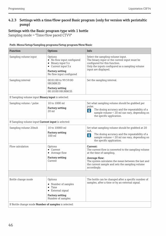
4.2.3 Settings with a time/flow-paced Basic program (only for version with peristaltic pump)
Settings with the Basic program type with 1 bottleSampling mode = "Time/flow paced CTVV"
Path: Menu/Setup/Sampling programs/Setup program/New/Basic
Function Options Info
Sampling volume input Options• No flow input configured• Binary input S:x• Current input S:x
Factory settingNo flow input configured
Select the sampling volume input.The binary input or the current input must be configured for this function.Only the inputs configured as a sampling volume input are displayed.
Sampling interval 00:01:00 to 99:59:00 HH:MM:SS
Factory setting00:10:00 HH:MM:SS
Set the sampling interval.
If Sampling volume input Binary input is selected:
Sampling volume / pulse 10 to 1000 ml
Factory setting20 ml
Set what sampling volume should be grabbed per pulse.
The dosing accuracy and the repeatability of a sample volume < 20 ml can vary, depending on the specific application.
If Sampling volume input Current input is selected:
Sampling volume 20mA 10 to 10000 ml
Factory setting100 ml
Set what sampling volume should be grabbed at 20 mA.
The dosing accuracy and the repeatability of a sample volume < 20 ml can vary, depending on the specific application.
Flow calculation Options• Current• Average flow
Factory settingCurrent
Current:The current flow is converted to the sampling volume at the time of sampling.
Average flow:The system calculates the mean between the last and the current sample and sets the sampling volume accordingly.
Bottle change mode Options
• Number of samples• Time• External signal
Factory settingNumber of samples
The bottle can be changed after a specific number of samples, after a time or by an external signal.
If Bottle change mode Number of samples is selected:

Liquistation CSF34 Programming
47
Samples per bottle 1 to 9999
Factory setting1
Set the number of samples.
If Bottle change mode Time is selected:
Time interval 00-00:02 to 31-00:00 DD-HH:MM
Factory setting00-01:00 DD-HH:MM
Set the time (days, hours and minutes) after which the system should change to the next bottle.
Bottle synchronization Options• None• 1. bottle change time• 1. Time of change + bottle
number
Factory settingNone
None:The time of sampling and bottle change are not synchronized.
1. bottle change time:Sampling starts with the first bottle.Set the synchronization time.
1. Time of change + bottle number:Each bottle is assigned to a specific fill time.Set the synchronization time and the weekday.
Start condition Options• Immediate• Date/time
Factory settingImmediate
The sampling program can be started either immediately or at a specific, configurable time.
If Start condition Date/time is selected:
Start date 01.01.2000 to 31.12.2099
Factory settingDD.MM.YYYY
Set the start date for the sampling program. The format depends on the option configured under general settings.
Start time 00:00:00 to 23:59:59
Factory settingHH:MM:SS (24h)
Set the time when the sampling program is started. The format depends on the option configured under general settings.
Stop condition Options• Program end• Continuous
Factory settingProgram end
Program end:The device stops sampling automatically once it has run through the set program.
Continuous:The device runs through the set program continuously in an infinite loop. Do not forget to empty the bottles.
Path: Menu/Setup/Sampling programs/Setup program/New/Basic
Function Options Info

Programming Liquistation CSF34
48
Settings with the Basic program type with multiple bottlesSampling mode = "Time/flow paced CTVV"
Assignment bin. output Options• No binary output config. for
state reporting• Binary output S:x
Factory settingNo binary output config. for state reporting
Assignment of the binary output to the program cycle.
Inputs Settings for the inputs can be made as described in the "Inputs" section.
Path: Menu/Setup/Sampling programs/Setup program/New/Basic
Function Options Info
Sampling volume input Options• No flow input configured• Binary input S:x• Current input S:x
Factory settingNo flow input configured
Select the sampling volume input.The binary input or the current input must be configured for this function.Only the inputs configured as a sampling volume input are displayed.
Sampling interval 00:01:00 to 99:59:00 HH:MM:SS
Factory setting00:10:00 HH:MM:SS
Set the sampling interval.
If Sampling volume input Binary input is selected:
Sampling volume / pulse 10 to 1000 ml
Factory setting20 ml
Set what sampling volume should be grabbed per pulse.
The dosing accuracy and the repeatability of a sample volume < 20 ml can vary, depending on the specific application.
If Sampling volume input Current input is selected:
Sampling volume 20mA 10 to 10000 ml
Factory setting100 ml
Set what sampling volume should be grabbed at 20 mA.
The dosing accuracy and the repeatability of a sample volume < 20 ml can vary, depending on the specific application.
Flow calculation Options• Current• Average flow
Factory settingCurrent
Current:The current flow is converted to the sampling volume at the time of sampling.
Average flow:The system calculates the mean between the last and the current sample and sets the sampling volume accordingly.
Path: Menu/Setup/Sampling programs/Setup program/New/Basic
Function Options Info

Liquistation CSF34 Programming
49
Bottle change mode Options• Number of samples• Time• External signal
Factory settingNumber of samples
The bottle can be changed either after a specific number of samples, after a time or by an external signal.
If Bottle change mode Number of samples is selected:
Samples per bottle 1 to 9999
Factory setting1
Set the number of samples.
If Bottle change mode Time is selected:
Time interval 00-00:02 to 31-00:00 DD-HH:MM
Factory setting00-01:00 DD-HH:MM
Set the time (in days, hours and minutes) after which the system should change to the next bottle.
Multiple bottles 0 to 23The configuration options depend on the current number of bottles
Factory setting0
Multiple bottles:"Simultaneous" transfer of two samples to separate bottles.
If Bottle change mode External signal is selected:
Bottle change signal input Options• No bottle change input
configured• Binary input S:x
Factory settingNo bottle change input configured
The bottle change input can be configured under Inputs .
Multiple bottles 0 to 23The configuration options depend on the current number of bottles
Factory setting0
Multiple bottles:"Simultaneous" transfer of two samples to separate bottles.
Start condition Options• Immediate• Date/time
Factory settingImmediate
The sampling program can be started either immediately or at a specific, configurable time.
Path: Menu/Setup/Sampling programs/Setup program/New/Basic
Function Options Info

Programming Liquistation CSF34
50
If Start condition Date/time is selected:
Start date 01.01.2000 to 31.12.2099
Factory settingDD.MM.YYYY
Set the start date for the sampling program. The format depends on the option configured under general settings.
Start time 00:00:00 to 23:59:59
Factory settingHH:MM:SS (24h)
Set the time when the sampling program is started. The format depends on the option configured under general settings.
Stop condition Options• Program end• Continuous
Factory settingProgram end
Program end:The device stops sampling automatically once it has run through the set program.
Continuous:The device runs through the set program continuously in an infinite loop. Do not forget to empty the bottles.
Assignment bin. output Options• No binary output config. for
state reporting• Binary output S:x
Factory settingNo binary output config. for state reporting
Assignment of the binary output to the program cycle.
Inputs Settings for the inputs can be made as described in the "Inputs" section.
Path: Menu/Setup/Sampling programs/Setup program/New/Basic
Function Options Info
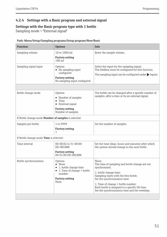
Liquistation CSF34 Programming
51
4.2.4 Settings with a Basic program and external signal
Settings with the Basic program type with 1 bottleSampling mode = "External signal"
Path: Menu/Setup/Sampling programs/Setup program/New/Basic
Function Options Info
Sampling volume 10 to 1000 ml
Factory setting100 ml
Enter the sample volume.
Sampling signal input Options• No sampling input
configured
Factory settingNo sampling input configured
Select the input for the sampling signal.The fieldbus must be configured for this function.
The sampling input can be configured under Inputs .
Bottle change mode Options
• Number of samples• Time• External signal
Factory settingNumber of samples
The bottle can be changed after a specific number of samples, after a time or by an external signal.
If Bottle change mode Number of samples is selected:
Samples per bottle 1 to 9999
Factory setting1
Set the number of samples.
If Bottle change mode Time is selected:
Time interval 00-00:02 to 31-00:00 DD-HH:MM
Factory setting00-01:00 DD-HH:MM
Set the time (days, hours and minutes) after which the system should change to the next bottle.
Bottle synchronization Options• None• 1. bottle change time• 1. Time of change + bottle
number
Factory settingNone
None:The time of sampling and bottle change are not synchronized.
1. bottle change time:Sampling starts with the first bottle.Set the synchronization time.
1. Time of change + bottle number:Each bottle is assigned to a specific fill time.Set the synchronization time and the weekday.
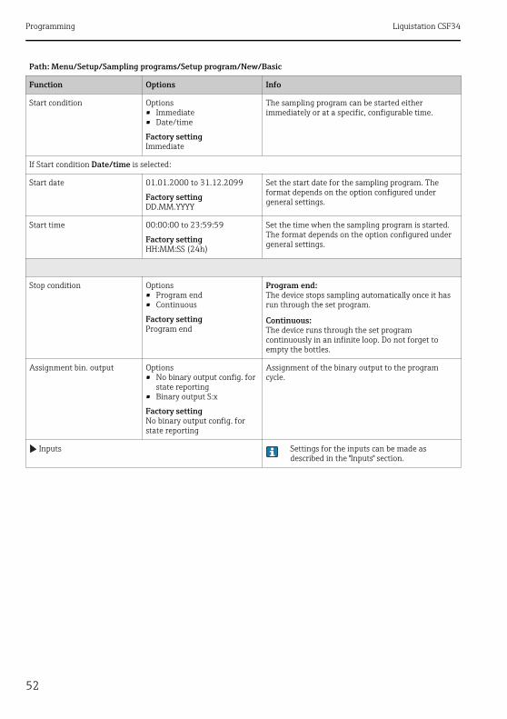
Programming Liquistation CSF34
52
Start condition Options• Immediate• Date/time
Factory settingImmediate
The sampling program can be started either immediately or at a specific, configurable time.
If Start condition Date/time is selected:
Start date 01.01.2000 to 31.12.2099
Factory settingDD.MM.YYYY
Set the start date for the sampling program. The format depends on the option configured under general settings.
Start time 00:00:00 to 23:59:59
Factory settingHH:MM:SS (24h)
Set the time when the sampling program is started. The format depends on the option configured under general settings.
Stop condition Options• Program end• Continuous
Factory settingProgram end
Program end:The device stops sampling automatically once it has run through the set program.
Continuous:The device runs through the set program continuously in an infinite loop. Do not forget to empty the bottles.
Assignment bin. output Options• No binary output config. for
state reporting• Binary output S:x
Factory settingNo binary output config. for state reporting
Assignment of the binary output to the program cycle.
Inputs Settings for the inputs can be made as described in the "Inputs" section.
Path: Menu/Setup/Sampling programs/Setup program/New/Basic
Function Options Info

Liquistation CSF34 Programming
53
Settings with the Basic program type with multiple bottlesSampling mode = "External signal"
Path: Menu/Setup/Sampling programs/Setup program/New/Basic
Function Options Info
Sampling volume 10 to 1000 ml
Factory setting100 ml
Enter the sample volume.
Sampling signal input Options• No sampling input
configured
Factory settingNo sampling input configured
Select the input for the sampling signal.The fieldbus must be configured for this function.
The sampling input can be configured under Inputs .
Bottle change mode Options• Number of samples• Time• External signal
Factory settingNumber of samples
The bottle can be changed either after a specific number of samples, after a time or by an external signal.
If Bottle change mode Number of samples is selected:
Samples per bottle 1 to 9999
Factory setting1
Set the number of samples.
If Bottle change mode Time is selected:
Time interval 00-00:02 to 31-00:00 DD-HH:MM
Factory setting00-01:00 DD-HH:MM
Set the time (in days, hours and minutes) after which the system should change to the next bottle.
If Bottle change mode External signal is selected:
Bottle change signal input Options• No bottle change input
configured
Factory settingNo bottle change input configured
The bottle change input can be configured under Inputs .
Multiple bottles 0 to 23The configuration options depend on the current number of bottles
Factory setting0
Multiple bottles:"Simultaneous" transfer of two samples to separate bottles.
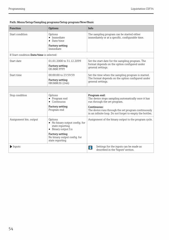
Programming Liquistation CSF34
54
Start condition Options• Immediate• Date/time
Factory settingImmediate
The sampling program can be started either immediately or at a specific, configurable time.
If Start condition Date/time is selected:
Start date 01.01.2000 to 31.12.2099
Factory settingDD.MM.YYYY
Set the start date for the sampling program. The format depends on the option configured under general settings.
Start time 00:00:00 to 23:59:59
Factory settingHH:MM:SS (24h)
Set the time when the sampling program is started. The format depends on the option configured under general settings.
Stop condition Options• Program end• Continuous
Factory settingProgram end
Program end:The device stops sampling automatically once it has run through the set program.
Continuous:The device runs through the set program continuously in an infinite loop. Do not forget to empty the bottles.
Assignment bin. output Options• No binary output config. for
state reporting• Binary output S:x
Factory settingNo binary output config. for state reporting
Assignment of the binary output to the program cycle.
Inputs Settings for the inputs can be made as described in the "Inputs" section.
Path: Menu/Setup/Sampling programs/Setup program/New/Basic
Function Options Info
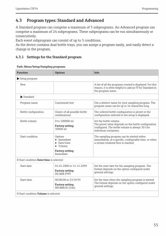
Liquistation CSF34 Programming
55
4.3 Program types: Standard and AdvancedA Standard program can comprise a maximum of 5 subprograms. An Advanced program can comprise a maximum of 24 subprograms. These subprograms can be run simultaneously or consecutively. Each event subprogram can consist of up to 3 conditions.As the device contains dual bottle trays, you can assign a program easily, and easily detect a change in the program.
4.3.1 Settings for the Standard program
Path: Menu/Setup/Sampling programs
Function Options Info
Setup program
New A list of all the programs created is displayed. For this reason, it is often helpful to add an "S" for Standard in the program name.
Standard
Program name Customized text Use a distinct name for your sampling program. The program name can be up to 16 characters long.
Bottle configuration Choice of all possible bottle combinations
The ordered bottle configuration is preset or the configuration selected in the setup is displayed.
Bottle volume 0 to 100000 ml
Factory setting30000 ml
Set the bottle volume.The preset value depends on the bottle configuration configured. The bottle volume is always 30 l for individual containers.
Start condition Options• Immediate• Date/time• Volume
Factory settingImmediate
The sampling program can be started either immediately, at a specific, configurable time, or when a certain totalized flow is reached.
If Start condition Date/time is selected:
Start date 01.01.2000 to 31.12.2099
Factory settingDD.MM.YYYY
Set the start date for the sampling program. The format depends on the option configured under general settings.
Start time 00:00:00 to 23:59:59
Factory settingHH:MM:SS (24h)
Set the time when the sampling program is started. The format depends on the option configured under general settings.
If Start condition Volume is selected:

Programming Liquistation CSF34
56
Start volume input Options• No flow input configured• Binary input S:x• Current input S:x
Factory settingNo flow input configured
Select the start volume input.The binary input or the current input must be configured for this function.Only the inputs configured for flow measurement are displayed.
Start flow sum 1.000 to 9999.000 m³
Factory setting10.000 m³
Set the start volume.
Stop condition Options• Program end• Continuous• Date/time
Factory settingProgram end
Program end:The device stops sampling automatically once it has run through the set program. All the assigned bottles are filled.
Continuous:The device runs through the set program continuously in an infinite loop. Do not forget to empty the bottles.
Date/time:The device stops the set program at a specific time.
If Stop condition Date/time is selected:
Stop date 01.01.2000 to 31.12.2099
Factory settingDD.MM.YYYY
Set the stop date for the sampling program. The format depends on the option configured under general settings.
Stop time 00:00:00 to 23:59:59
Factory settingHH:MM:SS (24h)
Set the time when the sampling program is stopped. The format depends on the option configured under general settings.
Setup subprogram
New
Programpart Use a distinct name for your subprogram. The program name can be up to 16 characters long.
Sampling mode Options• Time paced CTCV• Flow paced VTCV• Time/flow paced CTVV• External signal
Factory settingTime paced CTCV
Time paced CTCV:A constant sampling volume is taken at steady intervals.
Flow paced VTCV:A constant sampling volume is taken at variable intervals.
Time/flow paced CTVV(only for version with peristaltic pump):A variable sampling volume is taken at steady intervals.
External signalA pulse at the binary input starts a sampling cycle
Path: Menu/Setup/Sampling programs
Function Options Info

Liquistation CSF34 Programming
57
The settings that depend on the sampling mode are listed in the "Program type: Basic" section.
Enable subprogram Options• Immediate• Individual dates• Repeating date• Interval• Deactivation
Factory settingImmediate
Immediate:The subprogram is enabled immediately.
Individual dates:Set the start and stop dates for enabling the subprogram.
Repeating date:Set the start condition, activity time and repetition interval for the subprogram.
Interval:Set the start condition, activity time and inactivity time for the subprogram.
Deactivation:Only visible if there is more than one subprogram
If Enable subprogram Individual dates is selected:
Individual dates
Set the start and stop times for the subprogram. Enter a new date via "INSERT". Delete a date via "DELETE". You can assign a maximum of 25 start and stop dates.
If Enable subprogram Repeating date is selected:
Start condition Options• No delay• Date/Time• Time
Factory settingNo delay
No delay:The subprogram is started when the program is enabled.
Date/Time:Set the start date and start time for enabling the subprogram.
Time:Set the start time for enabling the subprogram.
Activity time 00:01 to 99:59 HH:MM
Factory setting00:01 HH:MM
Specify how long the subprogram should be active in hours and minutes.The time to be selected depends on the setting for the repetition mode.
Multiple date
Repetition mode Options• Daily interval• Weekly interval• Days of week
Factory settingDaily interval
Daily interval:Specify whether the subprogram should be repeated every day.
Weekly interval:Specify whether the subprogram should be repeated every week.
Days of week:Specify whether the subprogram should be repeated on certain days of the week.--> Select the days of the week in the subsequent menu item.
Path: Menu/Setup/Sampling programs
Function Options Info

Programming Liquistation CSF34
58
Repetition interval(only for Daily interval and Weekly interval)
1 to 999
Factory setting1
Specify for how many days or weeks the subprogram should be active.Example:Repetition mode = daily intervalRepetition interval = 2The subprogram is enabled every second day from the start condition.
If Enable subprogram Interval is selected:
Start condition Options• No delay• Date/Time• Time
Factory settingDate/Time
No delay:The subprogram is started when the program is enabled.
Date/Time:Set the start date and start time for enabling the subprogram.
Time:Set the start time for enabling the subprogram.
Start date 01.01.2000 to 31.12.2099
Factory settingDD.MM.YYYY
Set the start date for the 1st interval. The format depends on the option configured under general settings.
Start time 00:00:00 to 23:59:59
Factory settingHH:MM:SS (24h)
Set the time for the 1st interval. The format depends on the option configured under general settings.
Activity time 00-00:01 to 31-00:00 DD-HH:MM
Factory setting00-00:01 DD-HH:MM
Specify how long the subprogram should be active in days, hours and minutes. The subprogram always begins with an activation.
Inactivity time 00-00:01 to 31-00:00 DD-HH:MM
Factory setting00-00:01 DD-HH:MM
Specify how long the subprogram should be inactive in days, hours and minutes.
Sample at enable Options• No• Yes
Factory settingYes
Specify whether the first sample should be taken directly when the subprogram is enabled.For example, with intervals, a sample is taken at the start of every activation interval.
Sample at disable Options• No• Yes
Factory settingNo
Specify whether a sample should be taken when the subprogram is disabled.For example, with intervals, a sample is taken at the end of every activation interval.
Path: Menu/Setup/Sampling programs
Function Options Info
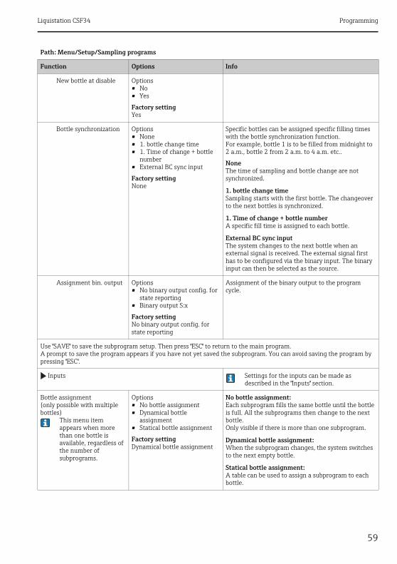
Liquistation CSF34 Programming
59
New bottle at disable Options• No• Yes
Factory settingYes
Bottle synchronization Options• None• 1. bottle change time• 1. Time of change + bottle
number• External BC sync input
Factory settingNone
Specific bottles can be assigned specific filling times with the bottle synchronization function. For example, bottle 1 is to be filled from midnight to 2 a.m., bottle 2 from 2 a.m. to 4 a.m. etc..
NoneThe time of sampling and bottle change are not synchronized.
1. bottle change timeSampling starts with the first bottle. The changeover to the next bottles is synchronized.
1. Time of change + bottle numberA specific fill time is assigned to each bottle.
External BC sync inputThe system changes to the next bottle when an external signal is received. The external signal first has to be configured via the binary input. The binary input can then be selected as the source.
Assignment bin. output Options• No binary output config. for
state reporting• Binary output S:x
Factory settingNo binary output config. for state reporting
Assignment of the binary output to the program cycle.
Use "SAVE" to save the subprogram setup. Then press "ESC" to return to the main program.A prompt to save the program appears if you have not yet saved the subprogram. You can avoid saving the program by pressing "ESC".
Inputs Settings for the inputs can be made as described in the "Inputs" section.
Bottle assignment(only possible with multiple bottles)
This menu item appears when more than one bottle is available, regardless of the number of subprograms.
Options• No bottle assignment• Dynamical bottle
assignment• Statical bottle assignment
Factory settingDynamical bottle assignment
No bottle assignment:Each subprogram fills the same bottle until the bottle is full. All the subprograms then change to the next bottle.Only visible if there is more than one subprogram.
Dynamical bottle assignment:When the subprogram changes, the system switches to the next empty bottle.
Statical bottle assignment:A table can be used to assign a subprogram to each bottle.
Path: Menu/Setup/Sampling programs
Function Options Info

Programming Liquistation CSF34
60
4.3.2 Settings for the Advanced program
Via the "Bottle change" menu item, the bottle change can be configured after a certain time or number of samples if bottle distribution with more than one bottle has been selected and either dynamic or static bottle assignment has been selected.
If Bottle assignment Statical bottle assignment is selected:
Bottle assignment table
Select a bottle and assign it a subprogram.
Inputs Settings for the inputs can be made as described in the "Inputs" section.
Path: Menu/Setup/Sampling programs
Function Options Info
Setup program
New A list of all the programs created is displayed. For this reason, it is often helpful to add an "A" for Advanced in the program name.
Advanced
Program name Customized text Use a distinct name for your sampling program. The program name can be up to 16 characters long.
Bottle configuration Choice of all possible bottle combinations
The ordered bottle configuration is preset or the configuration selected in the setup is displayed.
Bottle volume 10 to 100000 ml
Factory setting30000 ml
Set the bottle volume.The preset value depends on the bottle configuration configured. The bottle volume is always 30 l for individual containers.
Path: Menu/Setup/Sampling programs
Function Options Info

Liquistation CSF34 Programming
61
Start condition Options• Immediate• Date/time• Volume• External start• External duration• Fieldbus (optional)
Factory settingImmediate
ImmediateThe sampling program is started immediately.
Date/timeThe sampling program is started at a specific time that can be configured.
VolumeThe sampling program is started when a certain totalized flow is reached.
External startThe sampling program is started by a pulse at the configured binary input.
External durationThe sampling program is active as long as the configured input has the corresponding level.
Fieldbus(optional):The sampling program is started by a signal from the control system.
If Start condition Date/time is selected:
Start date 01.01.2000 to 31.12.2099
Factory settingDD.MM.YYYY
Set the start date for the sampling program. The format depends on the option configured under general settings.
Start time 00:00:00 to 23:59:59
Factory settingHH:MM:SS (24h)
Set the time when the sampling program is started. The format depends on the option configured under general settings.
If Start condition Volume is selected:
Start volume input Options• No flow input configured• Binary input S:x• Current input S:x
Factory settingNo flow input configured
Select the start volume input.The binary input or the current input must be configured for this function.Only the inputs configured for flow measurement are displayed.
Start flow sum 1.000 to 9999.000 m³
Factory setting10.000 m³
Set the start volume.
If Start condition External start is selected:
Start signal input Options• No program start input
configured• Binary input S:x
Factory settingNo program start input configured
Select the program start input.The binary input must be configured for this function.Only the inputs configured as a program start input are displayed.
If Start condition External duration is selected:
Path: Menu/Setup/Sampling programs
Function Options Info

Programming Liquistation CSF34
62
Start signal input Options• No program duration input
configured• Binary input S:x
Factory settingNo program duration input configured
Select the program duration input.The binary input must be configured for this function.Only the inputs configured as a program duration input are displayed.
If Start condition PROFIBUS DP or Modbus is selected:
Start signal input Options• None• %0V DO 01• %0V DO 02• %0V DO 03• %0V DO 04• %0V DO 05• %0V DO 06• %0V DO 07• %0V DO 08
Factory settingNone
Select the program start input.
Stop condition(not for External start)
Options• Program end• Continuous• Date/time• External signal• Fieldbus (optional)
Factory settingProgram end
Program end:The device stops sampling automatically once it has run through the set program.
Continuous:The device runs through the set program continuously in an infinite loop. Do not forget to empty the bottles.
Date/time:The device stops the set program at a specific time.
External signal:The device stops the set program if a pulse is sent to a binary input configured accordingly.
Fieldbus:The sampling program is stopped by a signal from the control system.
If Stop condition Date/time is selected:
Stop date 01.01.2000 to 31.12.2099
Factory settingDD.MM.YYYY
Set the stop date for the sampling program. The format depends on the option configured under general settings.
Stop time 00:00:00 to 23:59:59
Factory settingHH:MM:SS (24h)
Set the time when the sampling program is stopped. The format depends on the option configured under general settings.
If Stop condition External signal is selected:
Path: Menu/Setup/Sampling programs
Function Options Info

Liquistation CSF34 Programming
63
Stop signal input Options• No program stop input
configured• Binary input S:x
Factory settingNo program stop input configured
Select the program stop input.The binary input must be configured for this function.Only the inputs configured as a program stop input are displayed.
If Stop condition PROFIBUS DP or Modbus is selected:
Stop signal input Options• None• %0V DO 01• %0V DO 02• %0V DO 03• %0V DO 04• %0V DO 05• %0V DO 06• %0V DO 07• %0V DO 08
Factory settingNone
Select the program stop input.
Setup subprogram
New
Programpart Use a distinct name for your subprogram. The program name can be up to 16 characters long.
Sampling mode Options• Time paced CTCV• Flow paced VTCV• Time/flow paced CTVV• Single sample• Sampling table• External signal• Fieldbus (optional)
Factory settingTime paced CTCV
Time paced CTCV:A constant sampling volume is taken at steady intervals.
Flow paced VTCV:A constant sampling volume is taken at variable intervals.
Time/flow paced CTVV (only for version with peristaltic pump):A variable sampling volume is taken at steady intervals.
Single sample:The device takes a single sample with a specific volume.
Sampling table:The time and the sampling volume is assigned to a certain bottle in the sampling table.
External signal:A sample is taken when an external signal is received.
Fieldbus:The sampling cycle is triggered via the control system.
Path: Menu/Setup/Sampling programs
Function Options Info
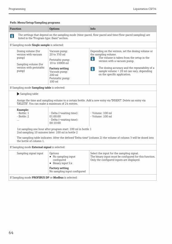
Programming Liquistation CSF34
64
The settings that depend on the sampling mode (time-paced, flow-paced and time/flow-paced sampling) are listed in the "Program type: Basic" section.
If Sampling mode Single sample is selected:
Dosing volume (for version with vacuum pump)
Sampling volume (for version with peristaltic pump)
Vacuum pump:20 to 350 ml
Peristaltic pump:10 to 10000 ml
Factory settingVacuum pump:200 mlPeristaltic pump:100 ml
Depending on the version, set the dosing volume or the sampling volume.
The volume is taken from the setup in the version with a vacuum pump.
The dosing accuracy and the repeatability of a sample volume < 20 ml can vary, depending on the specific application.
If Sampling mode Sampling table is selected:
Sampling table
Assign the time and sampling volume to a certain bottle. Add a new entry via "INSERT". Delete an entry via "DELETE". You can make a maximum of 24 entries.
Example:- Bottle: 1- Bottle: 2...
- Delta (=waiting time): 01:00:00- Delta (=waiting time): 00:10:00
- Volume: 100 ml- Volume: 100 ml
1st sampling one hour after program start: 100 ml in bottle 12nd sampling 10 minutes later: 100 ml in bottle 2
The sampling table indicates: After the defined "Delta time" (column 2) the volume of column 3 will be dosed into the bottle of column 1.
If Sampling mode External signal is selected:
Sampling signal input Options• No sampling input
configured• Binary input S:x
Factory settingNo sampling input configured
Select the input for the sampling signal.The binary input must be configured for this function.Only the configured inputs are displayed.
If Sampling mode PROFIBUS DP or Modbus is selected:
Path: Menu/Setup/Sampling programs
Function Options Info
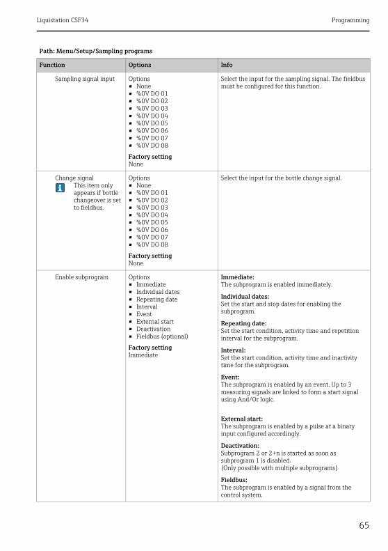
Liquistation CSF34 Programming
65
Sampling signal input Options• None• %0V DO 01• %0V DO 02• %0V DO 03• %0V DO 04• %0V DO 05• %0V DO 06• %0V DO 07• %0V DO 08
Factory settingNone
Select the input for the sampling signal. The fieldbus must be configured for this function.
Change signalThis item only appears if bottle changeover is set to fieldbus.
Options• None• %0V DO 01• %0V DO 02• %0V DO 03• %0V DO 04• %0V DO 05• %0V DO 06• %0V DO 07• %0V DO 08
Factory settingNone
Select the input for the bottle change signal.
Enable subprogram Options• Immediate• Individual dates• Repeating date• Interval• Event• External start• Deactivation• Fieldbus (optional)
Factory settingImmediate
Immediate:The subprogram is enabled immediately.
Individual dates:Set the start and stop dates for enabling the subprogram.
Repeating date:Set the start condition, activity time and repetition interval for the subprogram.
Interval:Set the start condition, activity time and inactivity time for the subprogram.
Event:The subprogram is enabled by an event. Up to 3 measuring signals are linked to form a start signal using And/Or logic.
External start:The subprogram is enabled by a pulse at a binary input configured accordingly.
Deactivation:Subprogram 2 or 2+n is started as soon as subprogram 1 is disabled.(Only possible with multiple subprograms)
Fieldbus:The subprogram is enabled by a signal from the control system.
Path: Menu/Setup/Sampling programs
Function Options Info
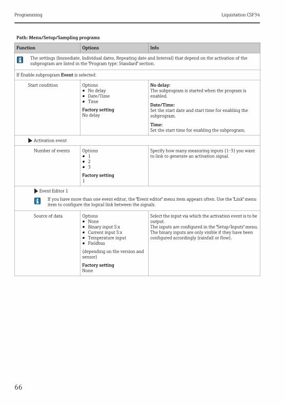
Programming Liquistation CSF34
66
The settings (Immediate, Individual dates, Repeating date and Interval) that depend on the activation of the subprogram are listed in the "Program type: Standard" section.
If Enable subprogram Event is selected:
Start condition Options• No delay• Date/Time• Time
Factory settingNo delay
No delay:The subprogram is started when the program is enabled.
Date/Time:Set the start date and start time for enabling the subprogram.
Time:Set the start time for enabling the subprogram.
Activation event
Number of events Options• 1• 2• 3
Factory setting1
Specify how many measuring inputs (1-3) you want to link to generate an activation signal.
Event Editor 1
If you have more than one event editor, the "Event editor" menu item appears often. Use the "Link" menu item to configure the logical link between the signals.
Source of data Options• None• Binary input S:x• Current input S:x• Temperature input• Fieldbus
(depending on the version and sensor)
Factory settingNone
Select the input via which the activation event is to be output.The inputs are configured in the "Setup/Inputs" menu.The binary inputs are only visible if they have been configured accordingly (rainfall or flow).
Path: Menu/Setup/Sampling programs
Function Options Info

Liquistation CSF34 Programming
67
Measured value Options (depends on sensor/data source)• None• Totalized flow• %0V AO 01• %0V AO 02• %0V AO 03• %0V AO 04• %0V DO 01• %0V DO 02• %0V DO 03• %0V DO 04• %0V DO 05• %0V DO 06• %0V DO 07• %0V DO 08
Factory settingNone
Operating mode Options• Upper limit• Lower limit• Within range• Out of range• Rate of change
Factory settingUpper limit
Type of limit value monitoring:• Limit value overshoot or undershoot• Measured value within or outside a range• Rate of change
Limit value Range of adjustment and factory settingDepends on the measured value
Operating mode="Above limit check" or "Below limit check"
• The event is triggered if the limit value + hysteresis is exceeded for the switch-on duration.
• The event is reset again if the limit value - hysteresis is undershot for the duration of the switch-off delay at least.
Range lower value Range of adjustment and factory settingDepends on the measured value
Operating mode="In range check" or "Out of range check"
• The event is triggered if the range lower value + hysteresis is exceeded for the switch-on duration.
• The event is reset again if the range upper value - hysteresis is undershot for the duration of the switch-off delay at least.
Range upper value
Hysteresis Range of adjustment and factory settingDepends on the measured value
The hysteresis is the difference between the switch-on point and the switch-off point if values, which cause the limit switch to pick up, become closer or move further apart. It is needed to ensure a stable switching behavior.
Start delay 0 to 9999 s
Factory setting0 s
Synonyms: pick-up and drop-out delay
Switch off delay
Path: Menu/Setup/Sampling programs
Function Options Info

Programming Liquistation CSF34
68
Delta value Range of adjustment and factory settingDepends on the measured value
Operating mode="Change rate"
The event is triggered if the measured value changes by at least the delta value (both positive and negative) within the set delta time. The event is deleted as soon as the rate of change is lower than the set value and the auto confirmation time has elapsed.
Delta time 00:01 to 23:59
Factory setting01:00
Auto Confirm 00:01 to 23:59
Factory setting00:01
If Enable subprogram External start is selected:
Activation input Options• No program part start input
configured• Binary input S:x
Factory settingNo program part start input configured
Select the input for start of the subprogram.The binary input must be configured for this function.Only the configured inputs are displayed.
If Enable subprogram PROFIBUS DP or Modbus is selected:
Activation signal Options• None• %0V DO 01• %0V DO 02• %0V DO 03• %0V DO 04• %0V DO 05• %0V DO 06• %0V DO 07• %0V DO 08
Factory settingNone
Enable subprogram via fieldbus.
Sample at enable(not for single sample and sampling table)
Options• No• Yes
Factory settingYes
Specify whether the first sample should be taken directly when the subprogram is enabled.
Sample at disable(not for single sample and sampling table and also not for "Immediate" and event)
Options• No• Yes
Factory settingNo
Specify whether a sample should be taken when the subprogram is disabled.
Path: Menu/Setup/Sampling programs
Function Options Info

Liquistation CSF34 Programming
69
Deactivation Options• Bottles full• Enable invalid• Deactivation with event
Factory settingEnable invalid
Select the disable function of the subprogram:
Bottles fullThe subprogram is disabled once all the assigned bottles have been filled.
Enable invalidDisable via limit value
Deactivation with eventNew parameter can be defined
Bottle change mode Options• No• Yes
Factory settingYes
No:The bottle is changed following a disable/enable
Yes:When the cycle is finished, the system continues filling the last bottle.
Synchronize samplings Options• To subprogram start• To clock
Factory settingTo subprogram start
To subprogram startThe intervals defined in the sampling mode are enabled when the subprogram is started.
To clockThe intervals defined in the sampling mode are enabled after a specific time.For example, if 30 min is entered this means that the interval is only activated at a time of xx:30.
--> You configure this time in the "Offset synchronization" menu item.
Bottle synchronization Options• None• 1. bottle change time• 1. Time of change + bottle
number• External BC sync input
Factory settingNone
Specific bottles can be assigned specific filling times with the bottle synchronization function. For example, bottle 1 is to be filled from midnight to 2 a.m., bottle 2 from 2 a.m. to 4 a.m. etc..
NoneThe time of sampling and bottle change are not synchronized.
1. bottle change timeSampling starts with the first bottle. The changeover to the next bottles is synchronized.
1. Time of change + bottle numberA specific fill time is assigned to each bottle.
External BC sync inputThe system changes to the next bottle when an external signal is received. The external signal first has to be configured via the binary input. The binary input can then be selected as the source.
Assignment bin. output Options• No binary output config. for
state reporting• Binary output S:x
Factory settingNo binary output config. for state reporting
Assignment of the binary output to the program cycle.
Path: Menu/Setup/Sampling programs
Function Options Info

Programming Liquistation CSF34
70
Use "SAVE" to save the subprogram setup. Then press "ESC" to return to the main program.
Inputs Settings for the inputs can be made as described in the "Inputs" section.
Bottle assignment(only possible with multiple bottles)
This menu item does not appear unless 2 or more bottles are available.
Options• No bottle assignment• Dynamical bottle
assignment• Statical bottle assignment
Factory settingNo bottle assignment
No bottle assignment:Each subprogram fills the same bottle until the bottle is full. All the subprograms then change to the next bottle.
Dynamical bottle assignment:When the subprogram changes, the system switches to the next bottle.
Statical bottle assignment:A table can be used to assign a subprogram to each bottle.
Via the "Bottle change" menu item, the bottle change can be configured after a certain time or number of samples if more than 1 subprogram is available and either dynamic or static bottle assignment has been selected.
If Bottle assignment Statical bottle assignment is selected:
Bottle assignment table
Select a bottle and assign it a subprogram.
Inputs Settings for the inputs can be made as described in the "Inputs" section.
Path: Menu/Setup/Sampling programs
Function Options Info
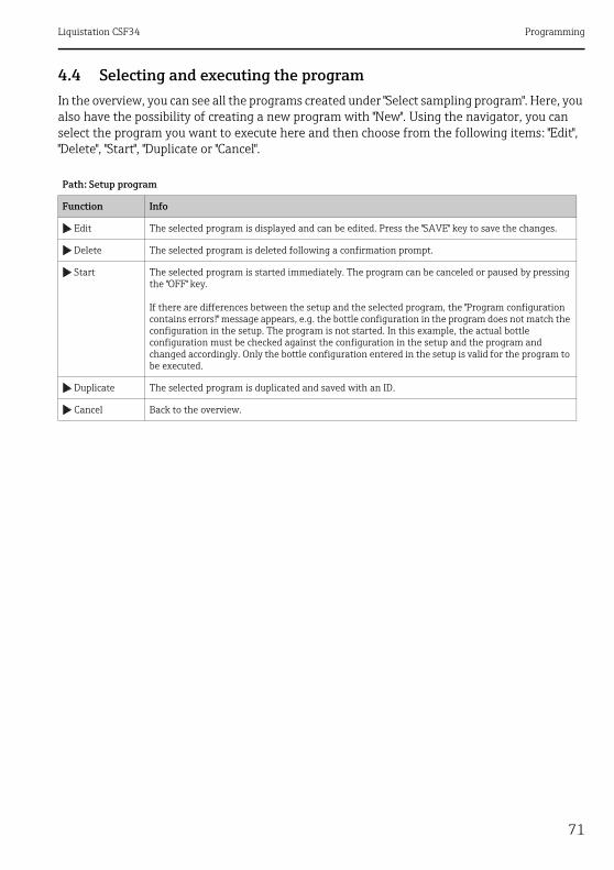
Liquistation CSF34 Programming
71
4.4 Selecting and executing the programIn the overview, you can see all the programs created under "Select sampling program". Here, you also have the possibility of creating a new program with "New". Using the navigator, you can select the program you want to execute here and then choose from the following items: "Edit", "Delete", "Start", "Duplicate or "Cancel".
Path: Setup program
Function Info
Edit The selected program is displayed and can be edited. Press the "SAVE" key to save the changes.
Delete The selected program is deleted following a confirmation prompt.
Start The selected program is started immediately. The program can be canceled or paused by pressing the "OFF" key.
If there are differences between the setup and the selected program, the "Program configuration contains errors!" message appears, e.g. the bottle configuration in the program does not match the configuration in the setup. The program is not started. In this example, the actual bottle configuration must be checked against the configuration in the setup and the program and changed accordingly. Only the bottle configuration entered in the setup is valid for the program to be executed.
Duplicate The selected program is duplicated and saved with an ID.
Cancel Back to the overview.

Programming Liquistation CSF34
72
The "Setup program" display contains the "ESC", "MAN", "?" and "OFF" soft keys.
Path: Setup program
Function Info
ESC Back to the overview.Any program currently running is canceled.
MAN Manual sampling can be configured and started here. Any program currently running is paused. -> See BA00478C "Commissioning", Sampling program/Manual sampling section
? A help text is displayed for the item.
OFF If no program is enabled, the device can be switched off here. If a program is enabled, the following options appear:
Power down sampler:Following a confirmation prompt, the device is set to the standby mode. Power continues to be supplied to the device and the LED flashes green.
Stop program %0V:1)
Stops a program currently running following a confirmation prompt. The overview display appears.
Pause program %0V:1)
Is selected if maintenance work is pending. The program is paused and the pause time is entered in the logbook. The current program is resumed when the "Resume program" button is pressed.
Path: Program active
Function Info
ESC Back to the overview.Any program currently running is canceled.
STAT For selecting statistics about measured values, sampling and inputsSee "Display settings" section in BA00478C.
OFF If no program is enabled, the device can be switched off here. If a program is enabled, the following options appear:
Power down sampler:Following a confirmation prompt, the device is set to the standby mode. Power continues to be supplied to the device and the LED flashes green.
Stop program %0V:1)
Stops a program currently running following a confirmation prompt. The overview display appears.
Pause program %0V:Is selected if maintenance work is pending. The program is paused and the pause time is entered in the logbook. The current program is resumed when the "Resume program" button is pressed.
1) "%0V" here stands for text that depends on the context. This text is generated automatically by the software and inserted in place of %0V. In the simplest situations, the generated text could be the name of the measuring channel, for example.

Liquistation CSF34 Outputs
73
5 Outputs
5.1 Binary outputsThe basic version of the device always has two binary outputs.
Possible application--> For outputting a manipulated variable to connected actuators
The binary output must be assigned in the program or subprogram before it can be activated.
Path: Menu/Setup/Outputs
Function Options Info
OutputBinary
Function Options• Off• Event• Limit value• Diagnostics message• Cleaning
(only for version with sensors with the Memosens protocol)
Factory settingOff
The following functions depend on the option selected.Function = "Off" switches off the function of the binary output and means no further settings are required.
For Cleaning:The outputs can only switch 100mA. A relay must be added to control valves or motors.
If Function: Event is selected:
Signal slope Options• Low-High• High-Low
Factory settingLow-High
Select the level change of the signal
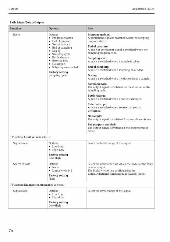
Outputs Liquistation CSF34
74
Event Options• Program enabled• End of program• Sampling start• End of sampling• Dosing• Sampling cycle• Bottle change• External stop• No sample• Sub program enabled
Factory settingSampling cycle
Program enabled:A permanent signal is switched when the sampling program starts.
End of program:A pulse or permanent signal is switched when the sampling program ends.
Sampling start:A pulse is switched when a sample is taken.
End of sampling:A pulse is switched when sampling has ended.
Dosing:A pulse is switched while the device doses a sample.
Sampling cycle:The output signal is switched for the duration of the sampling cycle.
Bottle change:A pulse is switched when a bottle is changed.
External stop:A pulse is switched when an external stop is performed.
No sample:The output signal is switched if no sample was taken.
Sub program enabled:The output signal is switched if this subprogram is active.
If Function: Limit value is selected:
Signal slope Options• Low-High• High-Low
Factory settingLow-High
Select the level change of the signal
Source of data Options• None• Limit switch 1-8
Factory settingNone
Select the limit switch via which the status of the relay is to be output.The limit switches are configured in the "Setup/Additional functions/LimitSwitch" menu.
If Function: Diagnostics message is selected:
Signal slope Options• Low-High• High-Low
Factory settingLow-High
Select the level change of the signal
Path: Menu/Setup/Outputs
Function Options Info
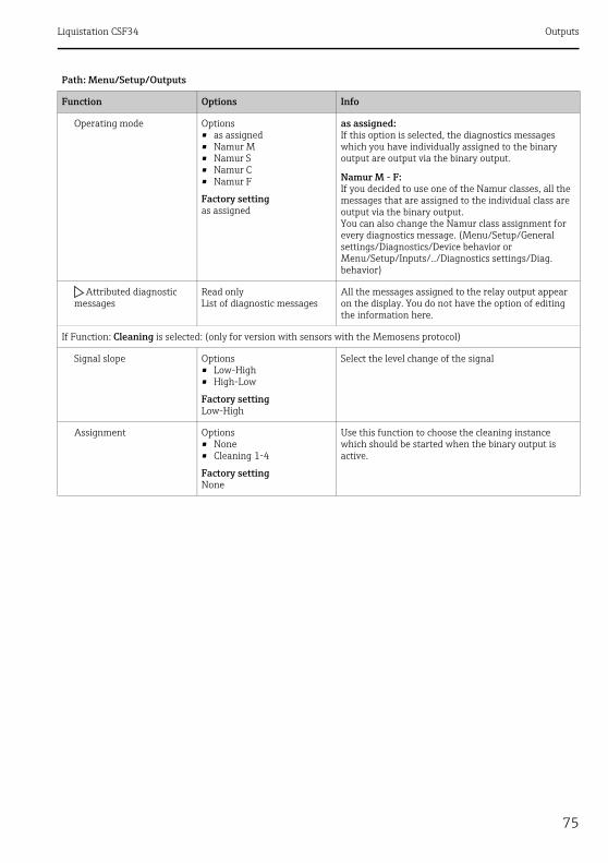
Liquistation CSF34 Outputs
75
Operating mode Options• as assigned• Namur M• Namur S• Namur C• Namur F
Factory settingas assigned
as assigned:If this option is selected, the diagnostics messages which you have individually assigned to the binary output are output via the binary output.
Namur M - F:If you decided to use one of the Namur classes, all the messages that are assigned to the individual class are output via the binary output.You can also change the Namur class assignment for every diagnostics message. (Menu/Setup/General settings/Diagnostics/Device behavior or Menu/Setup/Inputs/../Diagnostics settings/Diag. behavior)
Attributed diagnostic messages
Read onlyList of diagnostic messages
All the messages assigned to the relay output appear on the display. You do not have the option of editing the information here.
If Function: Cleaning is selected: (only for version with sensors with the Memosens protocol)
Signal slope Options• Low-High• High-Low
Factory settingLow-High
Select the level change of the signal
Assignment Options• None• Cleaning 1-4
Factory settingNone
Use this function to choose the cleaning instance which should be started when the binary output is active.
Path: Menu/Setup/Outputs
Function Options Info
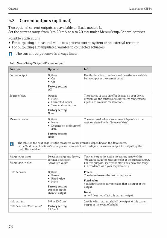
Outputs Liquistation CSF34
76
5.2 Current outputs (optional)Two optional current outputs are available on Basic module L.Set the current range from 0 to 20 mA or 4 to 20 mA under Menu/Setup/General settings.
Possible applications• For outputting a measured value to a process control system or an external recorder• For outputting a manipulated variable to connected actuators
The current output curve is always linear.
Path: Menu/Setup/Outputs/Current output
Function Options Info
Current output Options• On• Off
Factory settingOff
Use this function to activate and deactivate a variable being output at the current output
Source of data Options• None• Connected inputs• Temperature sensors
Factory settingNone
The sources of data on offer depend on your device version. All the sensors and controllers connected to inputs are available for selection.
Measured value Options• None• Depends on theSource of
data
Factory settingNone
The measured value you can select depends on the option selected under "Source of data".
The table on the next page lists the measured values available depending on the data source.In the "Additional functions" menu, you can also select and configure the current output for outputting the controlled variable.
Range lower value Selection range and factory settings depend on:"Measured value"
You can output the entire measuring range of the "Measured value" or just some of it at the current output. For this purpose, specify the start and end of the range in accordance with your requirements.
Range upper value
Hold behavior Options• Freeze• Fixed value• None
Factory settingDepends on the channel:output
FreezeThe device freezes the last current value.
Fixed valueYou define a fixed current value that is output at the output.
NoneA hold does not affect this current output.
Hold current
Hold behavior="Fixed value"
0.0 to 23.0 mA
Factory setting22.0 mA
Specify which current should be output at this current output in the event of a hold.

Liquistation CSF34 Outputs
77
Measured valuedepending on theSource of data
Source of data Measured value
pH Glass Options• Raw value mV• pH• Temperature
pH ISFET
Redox Options• Temperature• Redox mV• Redox %
Oxygen (amp.) Options• Temperature• Partial pressure• Concentration liquid• Saturation• Raw value nA(only Oxygen (amp.))• Raw value s(only Oxygen (opt.))
Oxygen (opt.)
Cond i Options• Temperature• Conductivity• Resistance(only Cond c)• Concentration(only Cond i)
Cond c
Chlorine Options• Temperature• Current• Concentration
ISE Options• Temperature• pH• Ammonium• Nitrate• Potassium• Chloride
TU/TS Options• Temperature• Turbidity g/l• Turbidity FNU
Nitrate Options• Temperature• NO3• NO3-N
Ultrasonic interface (interface measurement)
Options• Interface• Turbidity

Outputs Liquistation CSF34
78
5.3 Alarm relaysThe alarm relay is not available in devices with a battery backup system. The alarm relay is required to switch off the device completely when operating with the storage battery.
The following functions can be output via a relay• Limit switch status• Diagnostics messages• Status of a cleaning function in order to control a pump or a valve
You can assign a relay to multiple inputs in order to clean several sensors with just one cleaning unit, for example.
SAC Options• Temperature• SAC• Transm.• Absorption• COD• BOD
Current input 1-3 Options depend on the configuration
Temperature 1-3
Mathematical functions All the mathematical functions can also be used as a data source and the calcula-ted value can be used as the measured value.
Path: Menu/Setup/Outputs/Alarm relay or relay at channel no.
Function Options Info
Function Options• Off• LimitSwitch• Diagnostics• Cleaning
Factory settingOff
The following functions depend on the option selected.These versions are illustrated individually in the following section to provide a clearer understanding of the options.
Function="Off" switches off the relay function and means no further settings are required.
Measured valuedepending on theSource of data
Source of data Measured value
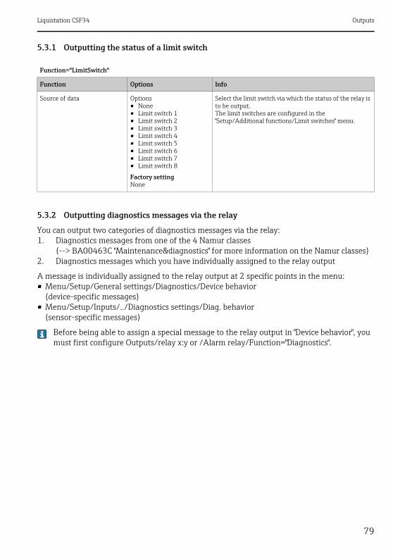
Liquistation CSF34 Outputs
79
5.3.1 Outputting the status of a limit switch
5.3.2 Outputting diagnostics messages via the relay
You can output two categories of diagnostics messages via the relay:1. Diagnostics messages from one of the 4 Namur classes
(--> BA00463C "Maintenance&diagnostics" for more information on the Namur classes)2. Diagnostics messages which you have individually assigned to the relay output
A message is individually assigned to the relay output at 2 specific points in the menu:• Menu/Setup/General settings/Diagnostics/Device behavior
(device-specific messages)• Menu/Setup/Inputs/../Diagnostics settings/Diag. behavior
(sensor-specific messages)
Before being able to assign a special message to the relay output in "Device behavior", you must first configure Outputs/relay x:y or /Alarm relay/Function="Diagnostics".
Function="LimitSwitch"
Function Options Info
Source of data Options• None• Limit switch 1• Limit switch 2• Limit switch 3• Limit switch 4• Limit switch 5• Limit switch 6• Limit switch 7• Limit switch 8
Factory settingNone
Select the limit switch via which the status of the relay is to be output.The limit switches are configured in the "Setup/Additional functions/Limit switches" menu.

Outputs Liquistation CSF34
80
5.3.3 Outputting the status of a cleaning function
Function="Diagnostics"
Function Options Info
Operating mode Options• as assigned• Namur M• Namur S• Namur C• Namur F
Factory settingas assigned
as assignedIf this option is selected, the diagnostics messages which you have individually assigned to the relay are output via the relay.
Namur M... FIf you decided to use one of the Namur classes, all the messages that are assigned to the individual class are output via the relay.You can also change the Namur class assignment for every diagnostics message.(Menu/Setup/General settings/Diagnostics/Device behavior or Menu/Setup/Inputs/../Diagnostics settings/Diag. behavior)
Attributed diagnostic messages
Operating mode="as assigned"
Read onlyList of diagnostic messages
All the messages assigned to the relay output appear on the display.You do not have the option of editing the information here.
Function="Cleaning"
Function Options Info
Assignment Options• None• Cleaning 1 - Water• Cleaning 1 - Cleaner• Cleaning 2 - Water• Cleaning 2 - Cleaner• Cleaning 3 - Water• Cleaning 3 - Cleaner• Cleaning 4 - Water• Cleaning 4 - Cleaner
Factory settingNone
Here you can specify how a cleaning function should be displayed for the alarm relay.
You can define the cleaning programs under:Menu/Setup/Additional functions/Cleaning.

Liquistation CSF34 Outputs
81
5.4 HARTSpecify which device variables should be output via HART communication.
You can define a maximum of 16 device variables:‣ Define the data source. You can choose from the sensor inputs and the controllers.‣ From the source, select the measured value that should be output.‣ Define how the device should behave in the event of a "Hold".‣ The configuration options for "Source of data", "Measured value" and "Hold behavior" are
identical to those described in the "Outputs/Current outputs" section. Please refer to this section for more information.
‣ Please note that if you select Hold behavior="Freeze", the system not only flags the status but also actually "freezes" the measured value.
More information is provided in BA00486C "HART communication".
5.5 PROFIBUS DP
5.5.1 Device variables (device --> PROFIBUS)
Specify which process values should be mapped to the PROFIBUS function blocks and are thereby available for transmission via PROFIBUS communication.
You can define a maximum of 16 device variables (AI Blocks):‣ Define the data source.
Choose between sensor inputs, current inputs or mathematical functions whose measured values should be transmitted.
‣ From the data source, select the measured value to be transmitted.
In addition, you can define 8 binary variables (DI Blocks):‣ Define the data source.
Select the limit switch or relay whose status should be transmitted.
5.5.2 PROFIBUS variables (PROFIBUS --> device)
Not in the "Menu/Setup/Outputs" menu‣ A maximum of 4 analog (AO) and 8 digital (DO) PROFIBUS variables are available as
measured values in the controller, limit switch or current output menus.‣ Example: Using an AO or DO value as the set point for the controller
– "Menu/Setup/Additional functions/Controller 1" menu– In the menu mentioned, define PROFIBUS as the data source.– Select the desired analog output (AO) or digital output (DO) as the measured value.
More information is provided in the "E+H Liquiline CM44x PROFIBUS Guideline" document on the CD.
Outputs Liquistation CSF34
82
5.6 Modbus RS485 and Modbus TCPSpecify which process values should be output via Modbus RS485 communication or via Modbus TCP.In the case of Modbus RS485, you can switch between the RTU and the ASCII protocol.
You can define a maximum of 16 device variables:‣ Define the data source. You can choose from the sensor inputs and the controllers.‣ From the source, select the measured value that should be output.‣ Define how the device should behave in the event of a "Hold".‣ The configuration options for "Source of data", "Measured value" and "Hold behavior" are
identical to those described in the "Outputs/Current outputs" section. Please refer to this section for more information.
‣ Please note that if you select Hold behavior="Freeze", the system not only flags the status but also actually "freezes" the measured value.
More information is provided in the "E+H Liquiline CM44x MODBUS Guideline" document.

Liquistation CSF34 Additional functions
83
6 Additional functions
6.1 Limit switchThere are different ways of configuring a limit switch:• Assigning a switch-on and switch-off point• Assigning a switch-on and switch-off delay for a relay• Setting an alarm threshold and also outputting an error message• Starting a cleaning function
Path: Menu/Setup/Additional functions/Limit switches/Limit switches 1 to 8
Function Options Info
Source of data Options• None• Connected sensors• Connected inputs• Temperature sensors
Factory settingNone
Specify the input or output which should be the source of data for the limit switch.
The sources of data on offer depend on your device version. All the sensors and controllers connected to inputs are available for selection.
Measuring value Options• None• Depends on theSource of
data
Factory settingNone
The measured value you can select depends on the option selected under "Source of data".
Measured valuedepending on theSource of data
Source of data Measured value
pH Glass Options• Raw value mV• pH• Temperature
pH ISFET
Redox Options• Temperature• Redox mV• Redox %
Oxygen (amp.) Options• Temperature• Partial pressure• Concentration liquid• Saturation• Raw value nA (only Oxygen (amp.))• Raw value s (only Oxygen (opt.))
Oxygen (opt.)

Additional functions Liquistation CSF34
84
Cond i Options• Temperature• Conductivity• Resistance (only Cond c)• Concentration (only Cond i)
Cond c
Chlorine Options• Temperature• Current• Concentration
ISE Options• Temperature• pH• Ammonium• Nitrate• Potassium• Chloride
TU/TS Options• Temperature• Turbidity g/l• Turbidity FNU
Nitrate Options• Temperature• NO3• NO3-N
Ultrasonic interface(interface measurement)
Options• Interface• Turbidity
SAC Options• Temperature• SAC• Transm.• Absorption• COD• BOD
Current input 1-3 The options for selection depend on the configuration
Temperature 1-3
Mathematical functions All the mathematical functions can also be used as a data source and the calculated value can be used as the measured value.
Measured valuedepending on theSource of data
Source of data Measured value

Liquistation CSF34 Additional functions
85
Path: Menu/Setup/Additional functions/Limit switches/Limit switches 1 to 8
Function Options Info
Cleaning program Options• None• Cleaning 1• Cleaning 2• Cleaning 3• Cleaning 4
Factory settingNone
Use this function to choose the cleaning instance which should be started when the limit switch is active.
Function Options• On• Off
Factory settingOff
Activating/deactivating the limit switch
Operating mode Options• Above limit check• Below limit check• In range check• Out of range check• Change rate
Factory settingAbove limit check
Type of limit value monitoring:• Limit value overshoot or undershoot å 8• Measured value within or outside a range å 9• aChange rate å 11
Limit value SettingsDepends on the measured value
Operating mode="Above limit check" or "Below limit check"
a0018080
Fig. 8: ÜExceeding (A) and undershooting (B) a limit value (without hysteresis and switch-on delay)
1 Limit value2 Alarm ranget1,t3,t5 No actiont2,t4 An event is generated
• If the measured values (MV) are increasing, the relay contact is closed when the on-value is exceeded ("Limit value" + "Hysteresis") and the start delay has elapsed ("Start delay").
• If the measured values are decreasing, the relay contact is reset when the off-value is undershot ("Limit value" - "Hysteresis") and following the release delay ("Switch off delay").

Additional functions Liquistation CSF34
86
Range lower value SettingsDepends on the measured value
Operating mode="In range check" or "Out of range check"
Range upper value
a0018081
Fig. 9: Monitoring outside (A) and within (B) a range (without hysteresis and switch-on delay)
1 End of range2 Start of range3 Alarm ranget1, 2, 3, 4 An event is generated
• If the measured values (MV) are increasing, the relay contact is closed when the on-value is exceeded ("Range lower value" + "Hysteresis") and the start delay has elapsed ("Start delay").
• If the measured values are decreasing, the relay contact is reset when the off-value is undershot ("Range upper value" - "Hysteresis") and following the release delay ("Switch off delay").
Hysteresis SettingsDepends on the measured value
Operating mode="In range check", "Out of range check","Above limit check" or "Below limit check"
a0018140
Fig. 10: Hysteresis taking the example of limit value overshoot
1 Limit value2 Alarm range3 Hysteresis ranget1, t2 An event is generated
The hysteresis is needed to ensure a stable switching behavior.
The device software adds or subtracts the value set here to/from the limit value (Limit value, Range lower value or Range upper value). This results in the double "Hysteresis" value for the hysteresis range around the limit value.An event is then only generated if the measured value (MV) completely passes through the hysteresis range. å 10
Path: Menu/Setup/Additional functions/Limit switches/Limit switches 1 to 8
Function Options Info
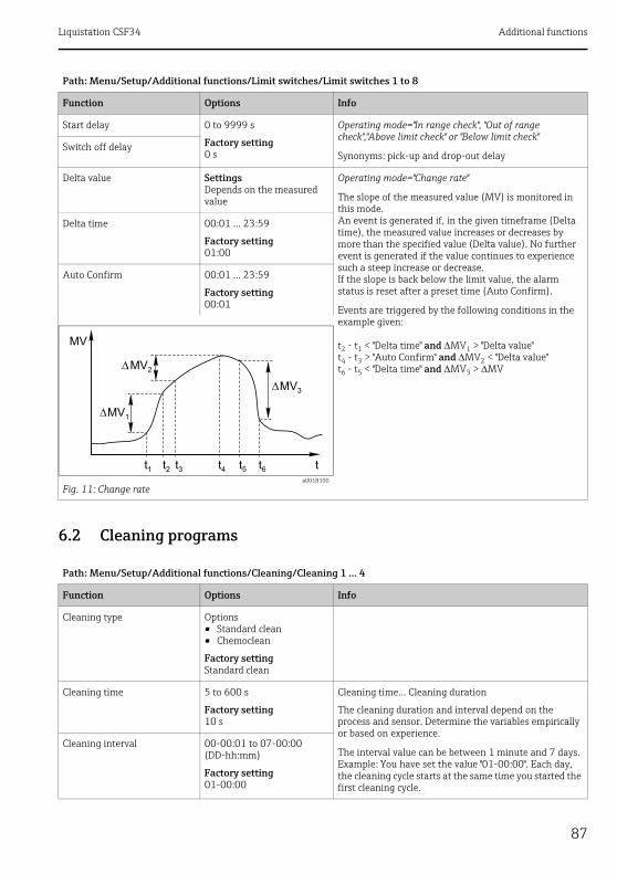
Liquistation CSF34 Additional functions
87
6.2 Cleaning programs
Start delay 0 to 9999 s
Factory setting0 s
Operating mode="In range check", "Out of range check","Above limit check" or "Below limit check"
Synonyms: pick-up and drop-out delaySwitch off delay
Delta value SettingsDepends on the measured value
Operating mode="Change rate"
The slope of the measured value (MV) is monitored in this mode.An event is generated if, in the given timeframe (Delta time), the measured value increases or decreases by more than the specified value (Delta value). No further event is generated if the value continues to experience such a steep increase or decrease.If the slope is back below the limit value, the alarm status is reset after a preset time (Auto Confirm).
Events are triggered by the following conditions in the example given:
t2 - t1 < "Delta time" and MV1 > "Delta value"t4 - t3 > "Auto Confirm" and MV2 < "Delta value"t6 - t5 < "Delta time" and MV3 > MV
Delta time 00:01 ... 23:59
Factory setting01:00
Auto Confirm 00:01 ... 23:59
Factory setting00:01
a0018100
Fig. 11: Change rate
Path: Menu/Setup/Additional functions/Cleaning/Cleaning 1 ... 4
Function Options Info
Cleaning type Options• Standard clean• Chemoclean
Factory settingStandard clean
Cleaning time 5 to 600 s
Factory setting10 s
Cleaning time... Cleaning duration
The cleaning duration and interval depend on the process and sensor. Determine the variables empirically or based on experience.
The interval value can be between 1 minute and 7 days.Example: You have set the value "01-00:00". Each day, the cleaning cycle starts at the same time you started the first cleaning cycle.
Cleaning interval 00-00:01 to 07-00:00 (DD-hh:mm)
Factory setting01-00:00
Path: Menu/Setup/Additional functions/Limit switches/Limit switches 1 to 8
Function Options Info

Additional functions Liquistation CSF34
88
Hold Options• On• Off
Factory settingOff
Decide whether there should be a hold for the assigned sensor during the cleaning process.
Output selection Goes to the "Outputs" menuYou can assign the cleaning program directly to one or more outputs.--> "Outputs" section
Start cycle Action Start the cyclical cleaning process with the settings above
Start manually Action Start an individual cleaning processIf cyclical cleaning is enabled, there are times in which it is not possible to manually start the process.
Stop Action End the cleaning process (cyclically or manually)
State of cleaning Read only Indicates whether cleaning is currently taking place or not
Time to next clean Read only Countdown to the next cleaning process(only if cyclical cleaning has been started)
Path: Menu/Setup/Additional functions/Cleaning/Cleaning 1 ... 4
Function Options Info

Liquistation CSF34 Additional functions
89
6.3 Mathematical functionsIn addition to "real" process values which are delivered by analog inputs or physical sensors connected to the device, you can also calculate a maximum of 6 "virtual" process values using mathematical functions.
The "virtual" process values can be:• Output via a current output or a fieldbus• Used as a controlled variable• Assigned as a measured variable to a limit contactor• Used as a measured variable to trigger cleaning• Displayed in user-defined measuring menus
6.3.1 Difference
You can subtract the measured values of two sensors and use the result to detect incorrect measurements, for example.To calculate a difference, you must use two measured values with the same engineering unit.
Path: Menu/Setup/Additional functions/Mathematical functions/MF 1 to 6/Mode/Difference
Function Options Info
Calculation Options• Off• On
Factory settingOff
On/off switch for the function
Y1 The options depend on the sensors connected
Select the sensors and the measured variables that should be used as the minuend (Y1) or subtrahend (Y2).
Measured value
Y2
Measured value
Difference value Read only View this value in a user-defined measuring screen or output the value via the current output.

Additional functions Liquistation CSF34
90
6.3.2 Redundancy
Use this function to monitor two or three sensors with redundant measurements. The arithmetic average of the two closest measured values is calculated and output as the redundancy value.
6.3.3 rH value
To calculate the rH value, a pH sensor and an ORP sensor must be connected. It is irrelevant whether you are using a pH glass sensor, an ISFET sensor or the pH electrode of an ISE sensor.
Path: Menu/Setup/Additional functions/Mathematical functions/MF 1 to 6/Mode/Redundancy
Function Options Info
Calculation Options• Off• On
Factory settingOff
On/off switch for the function
Y1 The options depend on the sensors connected
You can select different types of sensor that output the same measured value.
Example for temperature redundancy:You have a pH sensor and an oxygen sensor at inputs 1 and 2. Select both as "Y1" and "Y2". For "Measured value" select the temperature.
Measured value
Y2
Measured value
Y3 (optional)
Measured value
Deviation control Options• Off• On
Factory settingOff
You can monitor the redundancy. Specify an absolute limit value that may not be exceeded.
Deviation limit Depends on the selected measured value
Redundancy Read only View this value in a user-defined measuring screen or output the value via the current output.
Path: Menu/Setup/Additional functions/Mathematical functions/MF 1 to 6/Mode/rH calculation
Function Options Info
Calculation Options• Off• On
Factory settingOff
On/off switch for the function
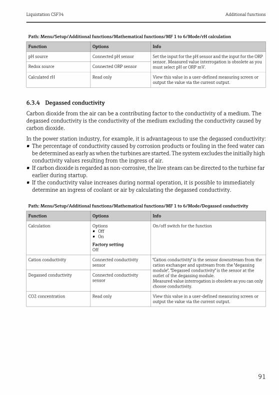
Liquistation CSF34 Additional functions
91
6.3.4 Degassed conductivity
Carbon dioxide from the air can be a contributing factor to the conductivity of a medium. The degassed conductivity is the conductivity of the medium excluding the conductivity caused by carbon dioxide.
In the power station industry, for example, it is advantageous to use the degassed conductivity:• The percentage of conductivity caused by corrosion products or fouling in the feed water can
be determined as early as when the turbines are started. The system excludes the initially high conductivity values resulting from the ingress of air.
• If carbon dioxide is regarded as non-corrosive, the live steam can be directed to the turbine far earlier during startup.
• If the conductivity value increases during normal operation, it is possible to immediately determine an ingress of coolant or air by calculating the degassed conductivity.
pH source Connected pH sensor Set the input for the pH sensor and the input for the ORP sensor. Measured value interrogation is obsolete as you must select pH or ORP mV.Redox source Connected ORP sensor
Calculated rH Read only View this value in a user-defined measuring screen or output the value via the current output.
Path: Menu/Setup/Additional functions/Mathematical functions/MF 1 to 6/Mode/Degassed conductivity
Function Options Info
Calculation Options• Off• On
Factory settingOff
On/off switch for the function
Cation conductivity Connected conductivity sensor
"Cation conductivity" is the sensor downstream from the cation exchanger and upstream from the "degassing module", "Degassed conductivity" is the sensor at the outlet of the degassing module.Measured value interrogation is obsolete as you can only choose conductivity.
Degassed conductivity Connected conductivity sensor
CO2 concentration Read only View this value in a user-defined measuring screen or output the value via the current output.
Path: Menu/Setup/Additional functions/Mathematical functions/MF 1 to 6/Mode/rH calculation
Function Options Info
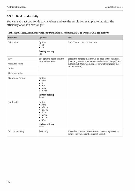
Additional functions Liquistation CSF34
92
6.3.5 Dual conductivity
You can subtract two conductivity values and use the result, for example, to monitor the efficiency of an ion exchanger.
Path: Menu/Setup/Additional functions/Mathematical functions/MF 1 to 6/Mode/Dual conductivity
Function Options Info
Calculation Options• Off• On
Factory settingOff
On/off switch for the function
Inlet The options depend on the sensors connected
Select the sensors that should be used as the minuend (Inlet, e.g. sensor upstream from the ion exchanger) and subtrahend (Outlet, e.g. sensor downstream from the ion exchanger).
Measured value
Outlet
Measured value
Main value format Options• Auto• #• #.#• #.##• #.###
Factory settingAuto
Cond. unit Options• Auto• μS/cm• mS/cm• S/cm• μS/m• mS/m• S/m
Factory settingAuto
Dual conductivity Read only View this value in a user-defined measuring screen or output the value via the current output.

Liquistation CSF34 Additional functions
93
6.3.6 Calculated pH value
The pH value can be calculated from the measured values of two conductivity sensors under certain conditions. Areas of application include power stations, steam generators and boiler feedwater.
Path: Menu/Setup/Additional functions/Mathematical functions/MF 1 to 6/Mode/pH calculation from conductivity
Function Options Info
Calculation Options• Off• On
Factory settingOff
On/off switch for the function
Method Options• NaOH• NH3• LiOH
Factory settingNaOH
The calculation is performed on the basis of Guideline VGB-R-450L of the Technical Association of Large Power Plant Operators ( Verband der Großkesselbetreiber, (VGB)).
NaOHpH = 11 + log {(v - 1/3 h)/273}NH3pH = 11 + log {(v - 1/3 h)/243}LiOHpH = 11 + log {(v - 1/3 h)/228}
v ... "Inlet" ... direct conductivityh ... "Outlet" ... acid conductivity
Inlet Choice of conductivity sensor
InletSensor upstream from the cation exchanger, "direct conductivity"OutletSensor downstream from the cation exchanger, "acid conductivity"The choice of measured value is obsolete since it must always be "Conductivity".
Outlet
Calculated pH Read only View this value in a user-defined measuring screen or output the value via the current output.

Communication Liquistation CSF34
94
7 Communication
7.1 Web server
7.1.1 Connection
‣ Connect the PC communication cable to the RJ45 port of module 485.
a0016228
Fig. 12: Ethernet connection
7.1.2 Creating the data connection
1. Start your PC.
2. First, set a manual IP address in the network connection settings of the operating system.
This address must be in the same subnetwork as the IP address of the device.
Example:
• IP address for Liquistation: 192.168.1.212 (Diagnostics/System information/Ethernet/IP-Address)
• IP address for the PC: 192.168.1.213
3. Start the Internet browser.
If you use a proxy server to connect to the Internet:
4. Disable the proxy (browser settings under "Connections/LAN settings").
5. Enter the IP address of your device in the address line.
The system takes a few moments to establish the connection and then the CM44 web server starts.

Liquistation CSF34 Communication
95
‣ Enter the following address(es) to download logbooks:
• 192.168.1.212/logbooks_csv.fhtml (for logbooks in CSV format)
• 192.168.1.212/logbooks_fdm.fhtml (for logbooks in FDM format)
Downloads in FDM format can be securely transmitted, saved and visualized with Endress+Hauser's "Field Data Manager Software".(--> www.products.endress.com/ms20)
7.1.3 Operation
The menu structure of the web server corresponds to the onsite operation.
a0016397
Fig. 13: Example of web server (menu/language=English)
• Clicking a menu name or a function corresponds to pressing the navigator.• You can make your settings conveniently via the computer keyboard.
Instead of using an Internet browser, you can also use FieldCare for configuration via ethernet. The ethernet DTM required for this purpose can be downloaded from the product page.
Menu/Setup
Device tag: Measuring point no. 1Device state: OK
Software version: 01.03.00
Basic setupGeneral settings
Inputs
OutputsAdditional functions
??
?
?
?
MENU
CAL
DIAG

Communication Liquistation CSF34
96
7.2 Service interfaceYou can connect the device to a computer via the service interface and configure it using "Fieldcare". Furthermore, configurations can also be saved, transferred and documented.
7.2.1 Connection
‣ Connect the service connector to the interface on the Liquiline basic module and connect it to the Commubox.
‣ Via the USB port, connect the Commubox to the computer running the Fieldcare software.
a0014953
Fig. 14: Connection overview
7.2.2 Creating the data connection
‣ Start Fieldcare.‣ Establish the connection to the Commubox. ‣ For this purpose, under "Host PC" click "Add device" and select "CDI Communication FXA291".‣ Click "Configuration" to select the serial interface for FXA291 and to set the baud rate
(115200).‣ Click "Link connection" to start communicating with the FXA291 ( are green).‣ Click "Add device" again and select your device type.‣ Click "Link connection" to start communicating with the device ( are green).‣ Select "Online parameterize" to be able to communicate with the device online.
You can now start online configuration via the DTM.Online configuration competes with onsite operation, i.e. each of the two options blocks the other one. Either side is able to prevent access from the other side.

Liquistation CSF34 Communication
97
7.2.3 Operation
• In the DTM the menu structure corresponds to the onsite operation. The functions of the Liquiline soft keys are found in the main window on the left.
• Clicking a menu name or a function corresponds to pressing the navigator.• You can make your settings conveniently via the computer keyboard.• Via Fieldcare, you can save logbooks, make backups of configurations and transfer the
configurations to other devices.• You can also print out configurations or save them as PDFs.
7.3 Fieldbuses
7.3.1 HART
You can communicate using the HART protocol via current output 1.‣ Connect the HART modem or handheld to current output 1 (communication load 230 - 500
Ohm).‣ Establish the connection via your HART device.‣ Operate Liquistation via the HART device. To do so, follow the instructions in the manual.
All the information on HART communication is provided on the CD (--> BA00486C).
7.3.2 PROFIBUS-DP
With the fieldbus module 485 and the appropriate device version, you can communicate via PROFIBUS DP.Connect the PROFIBUS data cable to the terminals of the fieldbus module as described (--> BA00443C "Commissioning").
7.3.3 Modbus
With the fieldbus module 485 and the appropriate device version, you can communicate via Modbus RS485 or Modbus TCP.Connect the Modbus data cable to the terminals of the fieldbus module (RS 485) or to the RJ45 (TCP) port as described (--> BA00443C "Commissioning").
Information on sensors with the Memosens protocol Liquistation CSF34
98
8 Information on sensors with the Memosens protocolThe options described below are only available on devices with a least one Memosens input.Sensors with the Memosens protocol have integrated electronics that save calibration data and other information. The sensor data are automatically communicated to the transmitter when the sensor is connected and are used to calculate the measured value.
Data digital sensors save include: • Manufacturer data
– Serial number– Order code– Date of manufacture
• Calibration data– Date of calibration– Calibration values– Number of calibrations– Serial number of the transmitter used to perform the last calibration
• Operating data– Date of initial commissioning– Hours of operation under extreme operating conditions– Sensor monitoring data
The specific data that are recorded and communicated to the transmitter depend on the sensor used. Differences can also occur within a sensor type.This causes different menu items to be displayed or hidden depending on the sensor connected.Pay attention to specific information in this manual.
Example:The amperometric oxygen sensor COS51D cannot be sterilized. For this reason, you will not be able to define limit values for sterilization in the diagnostics settings for this sensor. On the other hand, these menu items are displayed for a sterilizable amperometric sensor, such as COS22D.

Liquistation CSF34 Inputs: General
99
9 Inputs: General
9.1 ConfigurationAn input can be configured in one of two ways:1. Configuration where a sensor is not connected
‣ Select the appropriate channel.‣ From the list of sensor types, select the sensor which you want to configure.‣ Configure the channel as explained in following sections.‣ Connect the selected sensor type later on.
2. Configuration where a sensor is connected‣ Configure the channel as explained in following sections.
The following applies when configuring without a sensor:• Some settings require sensor communication.
You cannot make these settings if a sensor is not connected.• It is also possible to save a setup and transfer it to another device (see "Data management" in
the "General settings" section). This function might be a better option than performing a configuration when a sensor is not connected.
9.2 Frequently occurring functionsSome submenus are identical for all sensor types.These submenus are explained below so you can find a description of these menus at one central place. Instead of repeating the description, the sensor-specific section then only contains a reference to this chapter.
9.2.1 Damping
The damping causes a floating average curve of the measured values over the time specified.
Path: Menu/Setup/Inputs/<Sensor type>
Function Options Info
Damping <Sensor type> 0 to 600 s
Factory setting0 s
You specify the damping of the main measured value of the connected sensor and that of the integrated temperature sensor.Damping temp.
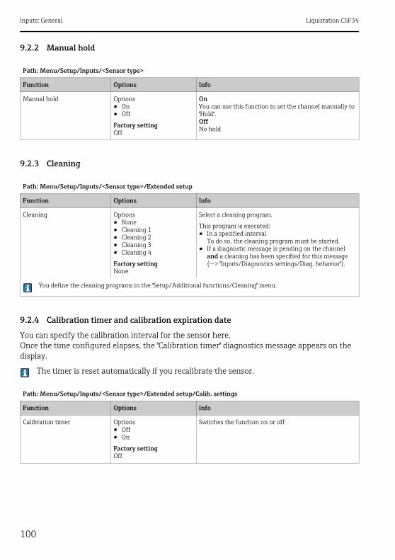
Inputs: General Liquistation CSF34
100
9.2.2 Manual hold
9.2.3 Cleaning
9.2.4 Calibration timer and calibration expiration date
You can specify the calibration interval for the sensor here.Once the time configured elapses, the "Calibration timer" diagnostics message appears on the display.
The timer is reset automatically if you recalibrate the sensor.
Path: Menu/Setup/Inputs/<Sensor type>
Function Options Info
Manual hold Options• On• Off
Factory settingOff
OnYou can use this function to set the channel manually to "Hold".OffNo hold
Path: Menu/Setup/Inputs/<Sensor type>/Extended setup
Function Options Info
Cleaning Options• None• Cleaning 1• Cleaning 2• Cleaning 3• Cleaning 4
Factory settingNone
Select a cleaning program.
This program is executed:• In a specified interval
To do so, the cleaning program must be started.• If a diagnostic message is pending on the channel
and a cleaning has been specified for this message (--> "Inputs/Diagnostics settings/Diag. behavior").
You define the cleaning programs in the "Setup/Additional functions/Cleaning" menu.
Path: Menu/Setup/Inputs/<Sensor type>/Extended setup/Calib. settings
Function Options Info
Calibration timer Options• Off• On
Factory settingOff
Switches the function on or off

Liquistation CSF34 Inputs: General
101
9.2.5 Process check system (PCS)
The process check system (PCS) checks the measuring signal for stagnation. An alarm is triggered if the measuring signal does not change over a certain period (several measured values).
Calibration timer value
Calibration timer="On"
14 to 365 d (chlorine sensor)1 to 10000 h (all others)
Factory setting180 d (chlorine sensor)1000 h (all others)
Specify the time after which the timer should have timed out. Once this time has elapsed, the "Calib. Timer" diagnostics message, along with the code 102, appears on the display.
Calib. expiration date Options• Off• On
Factory settingOff
The function checks whether the calibration of a sensor is still valid.Example: You install a precalibrated sensor. The function checks how much time has elapsed since the sensor was last calibrated. A diagnostics message is displayed if the time since the last calibration is longer than the predefined warning and alarm limit.
Calib. expiration date
Warning limit Factory setting11 months
Diagnostics message: 105 "Calib. validity"
Alarm limit Factory setting12 months
Diagnostics message: 104 "Calib. validity"
Warning and alarm limits mutually affect each other's possible ranges for adjustment.Range of adjustment which must include both limits: 1 to 24 monthsGenerally the following applies: alarm limit > warning limit
a0013107
Fig. 15: Normal measuring signal, no alarm
y Measuring signalyT Set value for "Tolerance width"
a0013106
Fig. 16: Stagnating signal, alarm is triggered
tD Set value for "Duration"tA Time when the alarm is triggered
Path: Menu/Setup/Inputs/<Sensor type>/Extended setup/Calib. settings
Function Options Info
t
y
yT
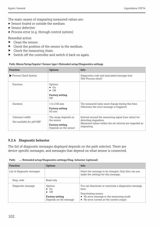
Inputs: General Liquistation CSF34
102
The main causes of stagnating measured values are:• Sensor fouled or outside the medium• Sensor defective• Process error (e.g. through control system)
Remedial action‣ Clean the sensor.‣ Check the position of the sensor in the medium.‣ Check the measuring chain.‣ Switch off the controller and switch it back on again.
9.2.6 Diagnostic behavior
The list of diagnostic messages displayed depends on the path selected. There are device-specific messages, and messages that depend on what sensor is connected.
Path: Menu/Setup/Inputs/<Sensor type>/Extended setup/Diagnostics settings
Function Options Info
Process Check System Diagnostics code and associated message text:904 "Process check"
Function Options• On• Off
Factory settingOff
Duration 1 to 240 min
Factory setting60 min
The measured value must change during this time. Otherwise the error message is triggered.
Tolerance width
Not available for pH/ORP
The range depends on the sensor
Factory settingDepends on the sensor
Interval around the measuring signal (raw value) for detecting stagnation.Measured values within the set interval are regarded as stagnating.
Path: ... /Extended setup/Diagnostics settings/Diag. behavior (optional)
Function Options Info
List of diagnostic messages Select the message to be changed. Only then can you make the settings for this message.
Diag. code Read only
Diagnostic message Options• On• Off
Factory settingDepends on the message
You can deactivate or reactivate a diagnostics message here.
Deactivating means:• No error message in the measuring mode• No error current at the current output

Liquistation CSF34 Inputs: General
103
Error current Options• On• Off
Factory settingDepends on the message
Decide whether an error current should be output at the current output if the diagnostic message display is activated.
In the event of general device errors, the error current is switched to all the current outputs. In the event of channel-specific errors, the error current is only switched to the current output concerned.
Status signal Options• Maintenance (M)• Out of specification (S)• Function check (C)• Failure (F)
Factory settingDepends on the message
The messages are divided into different error categories in accordance with NAMUR NE 107.
Decide whether you want to change a status signal assignment for your application.
Diag. output Options• None• Alarm relay• Relay 1 to n (depends on
the device version)
Factory settingNone
You can use this function to select a relay output and/or binary output to which the diagnostic message should be assigned.
For sensors with the Memosens protocol:Before you can assign the message to an output, you must first configure a relay output to "Diagnostics" (Menu/Setup/Outputs, assign the "Diagnostics" function and set the Operating mode to "as assigned").
Cleaning program(optional)
Options• None• Cleaning 1• Cleaning 2• Cleaning 3• Cleaning 4
Factory settingNone
Decide whether the diagnostic message should trigger a cleaning program.You can define the cleaning programs under:Menu/Setup/Additional functions/Cleaning.
Detail information Read only Here you can find more information on the diagnostic message and instructions on how to resolve the problem.
Path: ... /Extended setup/Diagnostics settings/Diag. behavior (optional)
Function Options Info
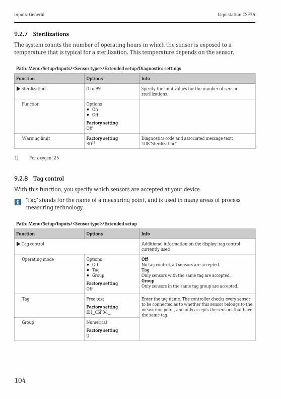
Inputs: General Liquistation CSF34
104
9.2.7 Sterilizations
The system counts the number of operating hours in which the sensor is exposed to a temperature that is typical for a sterilization. This temperature depends on the sensor.
9.2.8 Tag control
With this function, you specify which sensors are accepted at your device.
"Tag" stands for the name of a measuring point, and is used in many areas of process measuring technology.
Path: Menu/Setup/Inputs/<Sensor type>/Extended setup/Diagnostics settings
Function Options Info
Sterilizations 0 to 99 Specify the limit values for the number of sensor sterilizations.
Function Options• On• Off
Factory settingOff
Warning limit Factory setting301)
1) For oxygen: 25
Diagnostics code and associated message text:108 "Sterilization"
Path: Menu/Setup/Inputs/<Sensor type>/Extended setup
Function Options Info
Tag control Additional information on the display: tag control currently used
Operating mode Options• Off• Tag• Group
Factory settingOff
OffNo tag control, all sensors are accepted.TagOnly sensors with the same tag are accepted.GroupOnly sensors in the same tag group are accepted.
Tag Free text
Factory settingEH_CSF34_
Enter the tag name. The controller checks every sensor to be connected as to whether this sensor belongs to the measuring point, and only accepts the sensors that have the same tag.
Group Numerical
Factory setting0
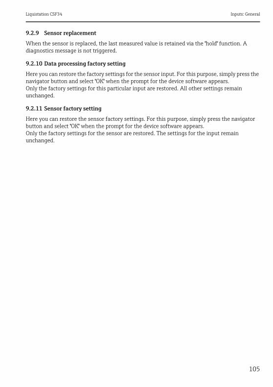
Liquistation CSF34 Inputs: General
105
9.2.9 Sensor replacement
When the sensor is replaced, the last measured value is retained via the "hold" function. A diagnostics message is not triggered.
9.2.10 Data processing factory setting
Here you can restore the factory settings for the sensor input. For this purpose, simply press the navigator button and select "OK" when the prompt for the device software appears.Only the factory settings for this particular input are restored. All other settings remain unchanged.
9.2.11 Sensor factory setting
Here you can restore the sensor factory settings. For this purpose, simply press the navigator button and select "OK" when the prompt for the device software appears.Only the factory settings for the sensor are restored. The settings for the input remain unchanged.
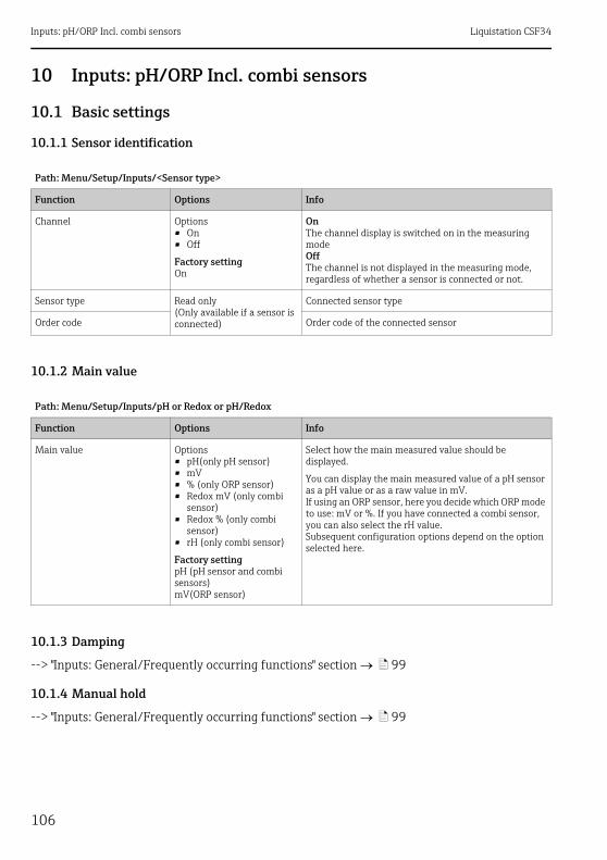
Inputs: pH/ORP Incl. combi sensors Liquistation CSF34
106
10 Inputs: pH/ORP Incl. combi sensors
10.1 Basic settings
10.1.1 Sensor identification
10.1.2 Main value
10.1.3 Damping
--> "Inputs: General/Frequently occurring functions" section ä 99
10.1.4 Manual hold
--> "Inputs: General/Frequently occurring functions" section ä 99
Path: Menu/Setup/Inputs/<Sensor type>
Function Options Info
Channel Options• On• Off
Factory settingOn
OnThe channel display is switched on in the measuring modeOffThe channel is not displayed in the measuring mode, regardless of whether a sensor is connected or not.
Sensor type Read only(Only available if a sensor is connected)
Connected sensor type
Order code Order code of the connected sensor
Path: Menu/Setup/Inputs/pH or Redox or pH/Redox
Function Options Info
Main value Options• pH(only pH sensor)• mV• % (only ORP sensor)• Redox mV (only combi
sensor)• Redox % (only combi
sensor)• rH (only combi sensor)
Factory settingpH (pH sensor and combi sensors)mV(ORP sensor)
Select how the main measured value should be displayed.
You can display the main measured value of a pH sensor as a pH value or as a raw value in mV.If using an ORP sensor, here you decide which ORP mode to use: mV or %. If you have connected a combi sensor, you can also select the rH value.Subsequent configuration options depend on the option selected here.

Liquistation CSF34 Inputs: pH/ORP Incl. combi sensors
107
10.2 Extended setup
10.2.1 Temperature and medium compensation (only pH)
10.2.2 Measured value formats
10.2.3 Cleaning
--> "Inputs: General/Frequently occurring functions" section ä 99
Path: Menu/Setup/Inputs/pH or pH/Redox/Extended setup
Function Options Info
Temp. compensation Options• Off• Automatic• Manual
Factory settingAutomatic
Decide how you want to compensate the medium temperature:• Automatically using the temperature sensor of your
sensor (ATC)• Manually by entering the medium temperature• Not at all
This setting only refers to compensation during measurement. You enter the compensation for calibration in the calibration settings.
Medium comp.
only pH sensor
Options• Off• 2-point• Table
Factory settingOff
Take a sample from the medium and determine its pH value at different temperatures in the lab.Decide whether you want to compensate using two points or several points in a table.
The dissociation of water changes with increasing temperature. The balance shifts towards the protons; the pH value drops. You can balance out this effect with the "Medium compensation" function.
Internal buffer(only pH glass or combi sensor)
pH 0 to 14
Factory settingpH 7.00
Only change the value if you are using a sensor with an internal buffer other than pH 7.
Path: Menu/Setup/Inputs/pH or Redox or pH/Redox/Extended setup
Function Options Info
Main value format(only pH)
Options• #.#• #.##
Factory setting#.#
Specify the number of decimal places for displaying the main measured value.
Temperature format Options• #.#• #.##
Factory setting#.#
Select how many decimal places should be used to display the temperature.
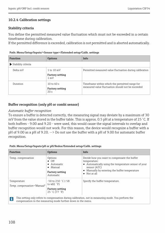
Inputs: pH/ORP Incl. combi sensors Liquistation CSF34
108
10.2.4 Calibration settings
Stability criteria
You define the permitted measured value fluctuation which must not be exceeded in a certain timeframe during calibration.If the permitted difference is exceeded, calibration is not permitted and is aborted automatically.
Buffer recognition (only pH or combi sensor)
Automatic buffer recognitionTo ensure a buffer is detected correctly, the measuring signal may deviate by a maximum of 30 mV from the value stored in the buffer table. This is approx. 0.5 pH at a temperature of 25˚C. If both buffers - 9.00 and 9.20 - were used, this would cause the signal intervals to overlap and buffer recognition would not work. For this reason, the device would recognize a buffer with a pH of 9.00 as a pH of 9.20. --> Do not use the buffer with a pH of 9.00 for automatic buffer recognition.
Path: Menu/Setup/Inputs/<Sensor type>/Extended setup/Calib. settings
Function Options Info
Stability criteria
Delta mV 1 to 10 mV
Factory setting1 mV
Permitted measured value fluctuation during calibration
Duration 10 to 60 s
Factory setting20 s
Timeframe within which the permitted range for measured value fluctuation should not be exceeded
Path: Menu/Setup/Inputs/pH or pH/Redox/Extended setup/Calib. settings
Function Options Info
Temp. compensation Options• Off• Automatic• Manual
Factory settingAutomatic
Decide how you want to compensate the buffer temperature:• Automatically using the temperature sensor of your
sensor (ATC)• Manually by entering the buffer temperature• Not at all
Temperature
Temp. compensation="Manual"
-50 to 250 ˚C (-58 to 482 ˚F)
Factory setting25 ˚C (77 ˚F)
Specify the buffer temperature.
This setting only refers to compensation during calibration, not in measuring mode. You perform the compensation in the measuring mode further down in the menu.

Liquistation CSF34 Inputs: pH/ORP Incl. combi sensors
109
Calibration timer and calibration expiration date
--> "Inputs: General/Frequently occurring functions" section ä 99
10.2.5 Diagnostics settings
This menu branch is used for specifying warning limits, and for defining whether and how diagnostics tools should be used.The associated diagnostics code is displayed for every setting.
Sensor check system (only pH glass or combi sensor)
The sensor check system (SCS) monitors the high impedance of the pH glass.An alarm is issued if a minimum impedance value is undershot or a maximum impedance is exceeded.• Glass breakage is the main reason for a drop in high impedance values.• The reasons for increasing impedance values include:
– Dry sensor– Worn pH glass membrane.
Buffer recognition Options• Fixed• Automatic(only pH glass
or combi sensor)• Manual
Factory settingFixed
FixedYou choose values from a list. This list depends on the setting for "Buffer manufacturer".
Automatic(only pH glass or combi sensor)The device recognizes the buffer automatically. The recognition depends on the setting for "Buffer manufacturer".
ManualYou enter any two buffer values. These must differ in terms of their pH value.
Buffer manufacturer Options• Endress+Hauser• Ingold/Mettler• DIN 19266• DIN 19267• Merck/Riedel• Hamilton• Special buffer
Factory settingEndress+Hauser
Temperature tables are stored internally in the unit for the following pH values:• Endress+Hauser
2.00 / 4.00 / 7.00 / (9.00) / 9.20 / 10.00 / 12.00• Ingold/Mettler
2.00 / 4.01 / 7.00 / 9.21• DIN 19266
1.68 / 4.01 / 6.86 / 9.18• DIN 19267
1.09 / 4.65 / 6.79 / 9.23 / 12.75• Merck/Riedel
2.00 / 4.01 / 6.98 / 8.95 / 12.00• Hamilton
1.09 / 1.68 / 2.00 / 3.06 / 4.01 / 5.00 / 6.007.00 / 8.00 / 9.21 / 10.01 / 11.00 / 12.00
You have the possibility of defining two buffers of your own with the "Special buffer" option. For this purpose, two tables are displayed in which you can enter value pH value/temperature value pairs.
Path: Menu/Setup/Inputs/pH or pH/Redox/Extended setup/Calib. settings
Function Options Info

Inputs: pH/ORP Incl. combi sensors Liquistation CSF34
110
The upper and lower limit values of the glass SCS value can be switched on or off independently of each other.
Slope (only pH or combi sensor)
The slope characterizes the sensor condition. The bigger the deviation from the ideal value (59 mV/pH) the poorer the condition of the sensor.
Path: Menu/Setup/Inputs/pH or pH/Redox/Extended setup/Diagnostics settings
Function Options Info
Glass impedance (SCS) 0 to 10000 M Specify your limit values for monitoring the impedance of the pH glass.
Upper limit Options• On• Off
Factory settingOn
OnSCS operates with the following settings for the upper warning and alarm limits.OffSCS is switched off.
Upper alarm limit Factory setting2000 M
Diagnostics code and associated message text:124 "Sensor glass"
Upper warning limit Factory setting1600 M
Diagnostics code and associated message text:125 "Sensor glass"
Lower limit Options• On• Off
Factory settingOn
OnSCS operates with the following settings for the lower warning and alarm limits.OffSCS is switched off.
Lower warning limit Factory setting1 M
Diagnostics code and associated message text:123 "Sensor glass"
Lower alarm limit Factory setting0 M
Diagnostics code and associated message text:122 "Sensor glass"
Path: Menu/Setup/Inputs/pH or pH/Redox/Extended setup/Diagnostics settings
Function Options Info
Slope 5.00 to 99.00 mV/pH Specify your limit values for slope monitoring.
Warning limit Factory setting55.00 mV/pH
Associated diagnostics code and message text:509 "Sensor calib."

Liquistation CSF34 Inputs: pH/ORP Incl. combi sensors
111
Zero point (only pH glass or combi sensor) or Operating point (only pH ISFET)
pH glass sensorsThe zero point characterizes the condition of the sensor reference. The bigger the deviation from the ideal value (pH 7.00) the poorer the condition. This can be caused by KCl dissolving away or reference contamination.
Sensor condition check (only pH glass or combi sensor)
Sensor condition check (SCC) monitors the electrode status and the degree of electrode aging. The electrode status is updated after every calibration.
The main reasons for a deteriorating electrode status are:• Glass membrane blocked or dry• Diaphragm (reference) blocked
Remedial action‣ Clean or regenerate the sensor.‣ Replace the sensor if this does not have the desired effect.
Path: Menu/Setup/Inputs/pH or pH/Redox/Extended setup/Diagnostics settings
Function Options Info
Zero point(pH glass or combi sensor)Operating point (pH ISFET)
pH glass-2.00 to 16.00
pH ISFET-950 mV to 950 mV
Specify your limit values for zero point or operating point monitoring.
Upper warning limit Factory settingpH 8.00 / 300 mV
Associated diagnostics code and message text:505 "Sensor calib." (pH glass)515 "Sensor calib." (pH ISFET)
Lower warning limit Factory settingpH 6.00 / -300 mV
Associated diagnostics code and message text:507 "Sensor calib." (pH glass)517 "Sensor calib." (pH ISFET)
Path: Menu/Setup/Inputs/pH or pH/Redox/Extended setup/Diagnostics settings
Function Options Info
Sensor Condition Check The function can only be switched on or off. It uses internal limit values
Function Options• On• Off
Factory settingOn
Diagnostics code and associated message text:127 "SCC sufficient"126 "SCC bad"
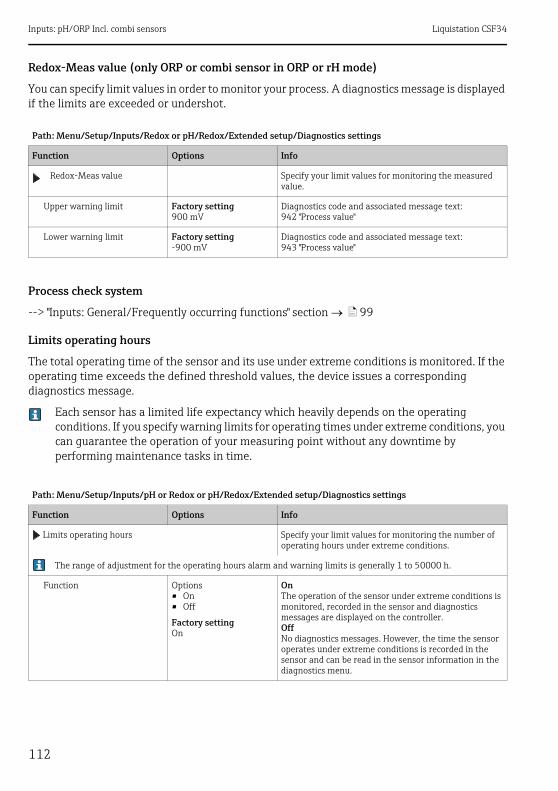
Inputs: pH/ORP Incl. combi sensors Liquistation CSF34
112
Redox-Meas value (only ORP or combi sensor in ORP or rH mode)
You can specify limit values in order to monitor your process. A diagnostics message is displayed if the limits are exceeded or undershot.
Process check system
--> "Inputs: General/Frequently occurring functions" section ä 99
Limits operating hours
The total operating time of the sensor and its use under extreme conditions is monitored. If the operating time exceeds the defined threshold values, the device issues a corresponding diagnostics message.
Each sensor has a limited life expectancy which heavily depends on the operating conditions. If you specify warning limits for operating times under extreme conditions, you can guarantee the operation of your measuring point without any downtime by performing maintenance tasks in time.
Path: Menu/Setup/Inputs/Redox or pH/Redox/Extended setup/Diagnostics settings
Function Options Info
Redox-Meas value Specify your limit values for monitoring the measured value.
Upper warning limit Factory setting900 mV
Diagnostics code and associated message text:942 "Process value"
Lower warning limit Factory setting-900 mV
Diagnostics code and associated message text:943 "Process value"
Path: Menu/Setup/Inputs/pH or Redox or pH/Redox/Extended setup/Diagnostics settings
Function Options Info
Limits operating hours Specify your limit values for monitoring the number of operating hours under extreme conditions.
The range of adjustment for the operating hours alarm and warning limits is generally 1 to 50000 h.
Function Options• On• Off
Factory settingOn
OnThe operation of the sensor under extreme conditions is monitored, recorded in the sensor and diagnostics messages are displayed on the controller.OffNo diagnostics messages. However, the time the sensor operates under extreme conditions is recorded in the sensor and can be read in the sensor information in the diagnostics menu.

Liquistation CSF34 Inputs: pH/ORP Incl. combi sensors
113
Delta slope(only pH)
The device determines the difference in slope between the last calibration and the penultimate calibration, and issues a warning or an alarm depending on the setting configured. The difference is an indicator for the condition of the sensor. The greater the change, the greater the wear experienced by the pH-sensitive glass membrane as a result of chemical corrosion or abrasion.
Operating time Total operating time of the sensor
Warning limit Factory setting10000 h
Diagnostics code and associated message text:199 "Operating time"
Operation > 80°C
Warning limit Factory setting10000 h
Diagnostics code and associated message text:193 "Operating time"
Operation > 100°C
Warning limit Factory setting10000 h
Diagnostics code and associated message text:194 "Operating time"
Operation < -300 mV only pH or combi sensor
Warning limit Factory setting10000 h
Diagnostics code and associated message text:180 "Operating time"
Operation > 300 mV only pH or combi sensor
Warning limit Factory setting10000 h
Diagnostics code and associated message text:179 "Operating time"
Path: Menu/Setup/Inputs/pH or pH/Redox/Extended setup/Diagnostics settings
Function Options Info
Delta slope 0.10 to 10.00 mV/pH Specify your limit values for monitoring the slope differential.
Function Options• On• Off
Factory settingOff
Warning limit Factory setting5.00 mV/pH
Diagnostics code and associated message text:518 "Sensor calib."
Path: Menu/Setup/Inputs/pH or Redox or pH/Redox/Extended setup/Diagnostics settings
Function Options Info

Inputs: pH/ORP Incl. combi sensors Liquistation CSF34
114
Delta zero point (only pH glass or combi sensor) or Delta operating point (only pH ISFET)
The device determines the difference between the last calibration and the penultimate calibration, and issues a warning or an alarm depending on the setting configured. The difference is an indicator for the condition of the sensor. The following applies to pH glass electrodes: The greater the change, the greater the wear experienced by the reference as a result of contaminating ions or KCl dissolving away.
Sterilizations
--> "Inputs: General/Frequently occurring functions" section ä 99
Diagnostic behavior
--> "Inputs: General/Frequently occurring functions" section ä 99
10.2.6 Tag control
--> "Inputs: General/Frequently occurring functions" section ä 99
10.2.7 Sensor replacement
--> "Inputs: General/Frequently occurring functions" section ä 99
10.2.8 Data processing factory setting
--> "Inputs: General/Frequently occurring functions" section ä 99
Path: Menu/Setup/Inputs/pH or pH/Redox/Extended setup/Diagnostics settings
Function Options Info
Delta zero point (pH glass or combi sensor) Delta operating point (pH ISFET)
pH glasspH 0.00 to 2.00
pH ISFET0 to 950 mV
Specify your limit values for monitoring the zero point or operating point differential.
Function Options• On• Off
Factory settingOff
Warning limit Factory settingpH 0.50 / 25 mV
Diagnostics code and associated message text:520 "Sensor calib." (pH glass)522 "Sensor calib." (pH ISFET)

Liquistation CSF34 Inputs: Conductivity
115
11 Inputs: Conductivity
11.1 Basic settings
11.1.1 Sensor identification
11.1.2 Damping
--> "Inputs: General/Frequently occurring functions" section ä 99
11.1.3 Manual hold
--> "Inputs: General/Frequently occurring functions" section ä 99
11.1.4 Operating mode and cell constant
Path: Menu/Setup/Inputs/<Sensor type>
Function Options Info
Channel Options• On• Off
Factory settingOn
OnThe channel display is switched on in the measuring modeOffThe channel is not displayed in the measuring mode, regardless of whether a sensor is connected or not.
Sensor type Read only(Only available if a sensor is connected)
Connected sensor type
Order code Order code of the connected sensor
Path: Menu/Setup/Inputs/Conductivity
Function Options Info
Operating mode Options• Conductivity• Resistance
(only Cond c)• Concentration
(only Cond i)• TDS
(only Cond c)
Factory settingConductivity
Alternatively to the conductivity, you can also measure the resistivity and the total dissolved solids (TDS) parameter with a conductive conductivity sensor.Alternatively to the conductivity, you can determine the concentration of the medium with an inductive conductivity sensor.
TDSTDS stands for all the organic and inorganic substances in the water in ionic, molecular or microgranular (<2 μm) form.Compared with laboratory methods (gravimetric analysis), TDS measurement via the conductivity value delivers a maximum measured error of less than 10%.
Cell constant Read only(Only available if a sensor is connected)
The cell constant of the connected sensor is displayed (--> sensor certificate)

Inputs: Conductivity Liquistation CSF34
116
11.1.5 Installation factor (only inductive sensors)
In confined installation conditions, the wall affects conductivity measurement in the liquid.The installation factor compensates for this effect. The transmitter corrects the cell constant by multiplying by the installation factor.The size of the installation factor depends on the diameter and the conductivity of the pipe nozzle, as well as the distance between the sensor and the wall. If there is a sufficient distance between the wall and the sensor (a > 15 mm (0.59"), from DN 80), the installation factor f does not have to be taken into consideration (f = 1.00). If distances from the wall are smaller, the installation factor is bigger for electrically insulating pipes (f >1), and smaller for electrically conductive pipes (f < 1).It can be measured using calibration solutions, or a close approximation determined from the following diagram.
a0005441
Fig. 17: Relation between the installation factor f and the wall distance
1 Electrically conductive pipe wall2 Electrically insulating pipe wall
Path: Menu/Setup/Inputs/Conductivity
Function Options Info
Inst. factor Read only(Only available if a sensor is connected)
Displays the current value. Only changes with a calibration.
1
2
a [inch]
0 5 10 15 20 2525 a [mm]
0.80
1.00
1.20
1.40
f
0.20 0.39 0.59 0.79 0.98

Liquistation CSF34 Inputs: Conductivity
117
11.1.6 Concentration table (only inductive sensors)
Example of a concentration table:
Values must be constantly increasing or decreasing.
Path: Menu/Setup/Inputs/Conductivity
Function Options Info
Conc. Table(Operating mode=Concentration)
Options• NaOH 0 to 15%• HCl 0 to 20%• HNO3 0 to 25%• HNO3 24 to 30%• H2SO4 0 to 28%• H2SO4 40 to 80%• H2SO4 93 to 100%• H3PO4 0 to 40%• NaCl 0 to 26%• User table 1• User table 2• User table 3• User table 4
Factory settingNaOH 0 to 15%
Concentration tables saved at the factory:NaOH: 0 to 15%, 0 to 100 ˚C (32 to 212 ˚F)HCl: 0 to 20%, 0 to 65 ˚C (32 to 149 ˚F)HNO3: 0 to 25%, 2 to 80 ˚C (36 to 176 ˚F)H2SO4: 0 to 28%, 0 to 100 ˚C (32 to 212 ˚F)H2SO4: 40 to 80%, 0 to 100 ˚C (32 to 212 ˚F)H2SO4: 93 to 100%, 0 to 100 ˚C (32 to 212 ˚F)H3PO4: 0 to 40%, 2 to 80 ˚C (36 to 176 ˚F)NaCl: 0 to 26%, 2 to 80 ˚C (36 to 176 ˚F)
Temp. comp. mode(Operating mode=Concentration)
Options• with temp. comp• without temp. comp
Factory settingwith temp. comp
Only select "without temp. comp" in very small temperature ranges.In all other cases, select "with temp. comp".
Table name(Conc. Table=one of the user tables)
Customized text, 16 characters
Assign a meaningful name to the selected table.
Edit table(Conc. Table=one of the user tables)
3-column table Assign conductivity and concentration value pairs for a specific temperature.
Conc. unit(Operating mode=Concentration)
Read only%
This is for information purposes only. No options are available.
Conductivity (uncompensated)
Concentration Temperature
1.000 mS/cm 0.000 mg/l 0.00 ˚C
2.000 mS/cm 0.000 mg/l 100.00 ˚C
100.0 mS/cm 3.000 mg/l 0.00 ˚C
300.0 mS/cm 3.000 mg/l 100.00 ˚C

Inputs: Conductivity Liquistation CSF34
118
11.1.7 Unit and format
11.1.8 Temperature compensation
Temperature coefficient = change in the conductivity per degree of temperature change:(T) = (T0)(1 + (T - T0))(T) ... conductivity at process temperature T(T0) ... conductivity at reference temperature T0
The temperature coefficient depends both on the chemical composition of the solution and the temperature itself.
Path: Menu/Setup/Inputs/Conductivity
Function Options Info
Main value format Options• Auto• #• #.#• #.##• #.###
Factory settingAuto
Specify the number of decimal places.
Cond. unit(Operating mode=Conductivity)
Unit(Operating mode=Resistance)
OptionsConductivity/resistance• Auto / Auto• μS/cm / Mm• mS/cm / Mcm• S/cm / kcm• μS/m / km• mS/m / m• S/m / cm
Factory settingAuto / Auto
The picklist depends on the operating mode.You can either choose from units for conductivity or units for resistivity.Since there are no options for concentration measurement, this function is not displayed for such measurements.
Path: Menu/Setup/Inputs/Conductivity
Function Options Info
Temp. source Options• Sensor• Manual
Factory settingSensor
Decide how you want to compensate the medium temperature:• Automatically using the temperature sensor of your
sensor• Manually by entering the medium temperature
Medium temperature(Temp. source=Manual)
-50.0 to 250.0 ˚C(-58.0 to 482.0 ˚F)
Factory setting25.0 ˚C (77 ˚F)
Enter the temperature of your medium.
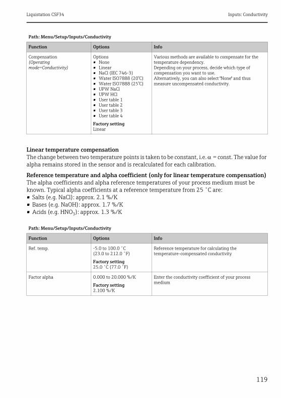
Liquistation CSF34 Inputs: Conductivity
119
Linear temperature compensationThe change between two temperature points is taken to be constant, i.e. = const. The value for alpha remains stored in the sensor and is recalculated for each calibration.
Reference temperature and alpha coefficient (only for linear temperature compensation)The alpha coefficients and alpha reference temperatures of your process medium must be known. Typical alpha coefficients at a reference temperature from 25 ˚C are:• Salts (e.g. NaCl): approx. 2.1 %/K• Bases (e.g. NaOH): approx. 1.7 %/K• Acids (e.g. HNO3): approx. 1.3 %/K
Compensation(Operating mode=Conductivity)
Options• None• Linear• NaCl (IEC 746-3)• Water ISO7888 (20°C)• Water ISO7888 (25°C)• UPW NaCl• UPW HCl• User table 1• User table 2• User table 3• User table 4
Factory settingLinear
Various methods are available to compensate for the temperature dependency.Depending on your process, decide which type of compensation you want to use.Alternatively, you can also select "None" and thus measure uncompensated conductivity.
Path: Menu/Setup/Inputs/Conductivity
Function Options Info
Ref. temp. -5.0 to 100.0 ˚C(23.0 to 212.0 ˚F)
Factory setting25.0 ˚C (77.0 ˚F)
Reference temperature for calculating the temperature-compensated conductivity
Factor alpha 0.000 to 20.000 %/K
Factory setting2.100 %/K
Enter the conductivity coefficient of your process medium
Path: Menu/Setup/Inputs/Conductivity
Function Options Info
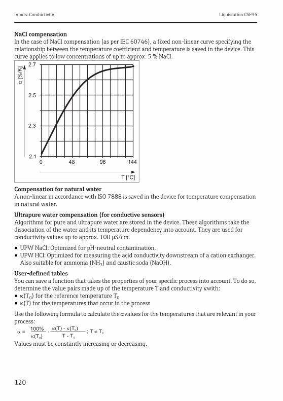
Inputs: Conductivity Liquistation CSF34
120
NaCl compensationIn the case of NaCl compensation (as per IEC 60746), a fixed non-linear curve specifying the relationship between the temperature coefficient and temperature is saved in the device. This curve applies to low concentrations of up to approx. 5 % NaCl.
Compensation for natural waterA non-linear in accordance with ISO 7888 is saved in the device for temperature compensation in natural water.
Ultrapure water compensation (for conductive sensors)Algorithms for pure and ultrapure water are stored in the device. These algorithms take the dissociation of the water and its temperature dependency into account. They are used for conductivity values up to approx. 100 μS/cm.
• UPW NaCl: Optimized for pH-neutral contamination.• UPW HCl: Optimized for measuring the acid conductivity downstream of a cation exchanger.
Also suitable for ammonia (NH3) and caustic soda (NaOH).
User-defined tablesYou can save a function that takes the properties of your specific process into account. To do so, determine the value pairs made up of the temperature T and conductivity with:• (0) for the reference temperature T0• (T) for the temperatures that occur in the process
Use the following formula to calculate the values for the temperatures that are relevant in your process:
Values must be constantly increasing or decreasing.
0 48 96 1442.1
2.3
2.5
2.7
T [°C]
�[%
/K]

Liquistation CSF34 Inputs: Conductivity
121
11.2 Extended setup
11.2.1 Temperature format
11.2.2 Cleaning
--> "Inputs: General/Frequently occurring functions" section ä 99
11.2.3 Diagnostics settings
This menu branch is used for specifying warning limits, and for defining whether and how diagnostics tools should be used.The associated diagnostics code is displayed for every setting.
Process check system
--> "Inputs: General/Frequently occurring functions" section ä 99
Path: Menu/Setup/Inputs/Conductivity
Function Options Info
Temp. comp. mode
(Compensation=one of the user tables)
Options• Conductivity• Coeff. Alpha
Factory settingConductivity
ConductivityYou specify the temperature, conductivity and uncompensated conductivity. Recommended for large measuring ranges and small measured values.Coeff. AlphaAs the value pairs, you specify an alpha value and the related temperature.
Table name
(Compensation=one of the user tables)
Customized text, 16 characters
Assign a meaningful name to the selected table.
Edit table(Compensation=one of the user tables)
• Temperature• Conductivity• Temperature comp. cond.
or
• Temperature• Coefficient alpha
Maximum number of rows: 25The type of table depends on the option under "Temp. comp. mode".
Path: Menu/Setup/Inputs/<Sensor type>/Extended setup
Function Options Info
Temperature format Options• #.#• #.##
Factory setting#.#
Select how many decimal places should be used to display the temperature.
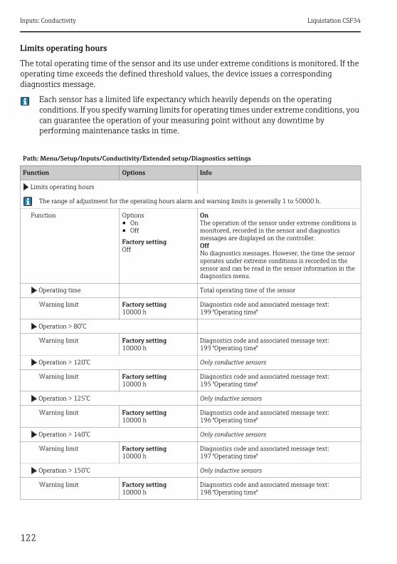
Inputs: Conductivity Liquistation CSF34
122
Limits operating hours
The total operating time of the sensor and its use under extreme conditions is monitored. If the operating time exceeds the defined threshold values, the device issues a corresponding diagnostics message.
Each sensor has a limited life expectancy which heavily depends on the operating conditions. If you specify warning limits for operating times under extreme conditions, you can guarantee the operation of your measuring point without any downtime by performing maintenance tasks in time.
Path: Menu/Setup/Inputs/Conductivity/Extended setup/Diagnostics settings
Function Options Info
Limits operating hours
The range of adjustment for the operating hours alarm and warning limits is generally 1 to 50000 h.
Function Options• On• Off
Factory settingOff
OnThe operation of the sensor under extreme conditions is monitored, recorded in the sensor and diagnostics messages are displayed on the controller.OffNo diagnostics messages. However, the time the sensor operates under extreme conditions is recorded in the sensor and can be read in the sensor information in the diagnostics menu.
Operating time Total operating time of the sensor
Warning limit Factory setting10000 h
Diagnostics code and associated message text:199 "Operating time"
Operation > 80°C
Warning limit Factory setting10000 h
Diagnostics code and associated message text:193 "Operating time"
Operation > 120°C Only conductive sensors
Warning limit Factory setting10000 h
Diagnostics code and associated message text:195 "Operating time"
Operation > 125°C Only inductive sensors
Warning limit Factory setting10000 h
Diagnostics code and associated message text:196 "Operating time"
Operation > 140°C Only conductive sensors
Warning limit Factory setting10000 h
Diagnostics code and associated message text:197 "Operating time"
Operation > 150°C Only inductive sensors
Warning limit Factory setting10000 h
Diagnostics code and associated message text:198 "Operating time"
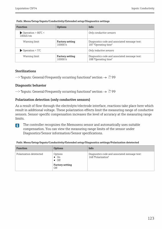
Liquistation CSF34 Inputs: Conductivity
123
Sterilizations
--> "Inputs: General/Frequently occurring functions" section ä 99
Diagnostic behavior
--> "Inputs: General/Frequently occurring functions" section ä 99
Polarization detection (only conductive sensors)
As a result of flow through the electrolyte/electrode interface, reactions take place here which result in additional voltage. These polarization effects limit the measuring range of conductive sensors. Sensor-specific compensation increases the level of accuracy at the measuring range limits.
The controller recognizes the Memosens sensor and automatically uses suitable compensation. You can view the measuring range limits of the sensor under Diagnostics/Sensor information/Sensor specifications.
Operation > 80°C < 100nS/cm
Only conductive sensors
Warning limit Factory setting10000 h
Diagnostics code and associated message text:187 "Operating time"
Operation < 5°C Only inductive sensors
Warning limit Factory setting10000 h
Diagnostics code and associated message text:188 "Operating time"
Path: Menu/Setup/Inputs/Conductivity/Extended setup/Diagnostics settings/Polarization detetected
Function Options Info
Polarization detetected Options• On• Off
Factory settingOff
Diagnostics code and associated message text:168 "Polarization"
Path: Menu/Setup/Inputs/Conductivity/Extended setup/Diagnostics settings
Function Options Info
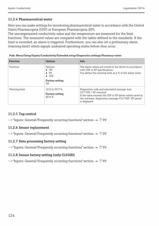
Inputs: Conductivity Liquistation CSF34
124
11.2.4 Pharmaceutical water
Here you can make settings for monitoring pharmaceutical water in accordance with the United States Pharmacopeia (USP) or European Pharmacopeia (EP).The uncompensated conductivity value and the temperature are measured for the limit functions. The measured values are compared with the tables defined in the standards. If the limit is exceeded, an alarm is triggered. Furthermore, you can also set a preliminary alarm (warning limit) which signals undesired operating states before they occur.
11.2.5 Tag control
--> "Inputs: General/Frequently occurring functions" section ä 99
11.2.6 Sensor replacement
--> "Inputs: General/Frequently occurring functions" section ä 99
11.2.7 Data processing factory setting
--> "Inputs: General/Frequently occurring functions" section ä 99
11.2.8 Sensor factory setting (only CLS50D)
--> "Inputs: General/Frequently occurring functions" section ä 99
Path: Menu/Setup/Inputs/Conductivity/Extended setup/Diagnostics settings/Pharmacy-water
Function Options Info
Function Options• Off• EP• USP
Factory settingOff
The alarm values are stored in the device in accordance with USP or EP specifications.You define the warning limit as a % of the alarm value.
Warning limit 10.0 to 99.9 %
Factory setting80.0 %
Diagnostics code and associated message text:915 "USP / EP warning"If the value exceeds the USP or EP alarm values saved in the software, diagnostics message 914 "USP/ EP alarm" is displayed.

Liquistation CSF34 Inputs: Oxygen
125
12 Inputs: Oxygen
12.1 Basic settings
12.1.1 Sensor identification
12.1.2 Main value
12.1.3 Damping
--> "Inputs: General/Frequently occurring functions" section ä 99
Path: Menu/Setup/Inputs/<Sensor type>
Function Options Info
Channel Options• On• Off
Factory settingOn
OnThe channel display is switched on in the measuring modeOffThe channel is not displayed in the measuring mode, regardless of whether a sensor is connected or not.
Sensor type Read only(Only available if a sensor is connected)
Connected sensor type
Order code Order code of the connected sensor
Path: Menu/Setup/Inputs/DO
Function Options Info
Main value Options• Concentration liquid• Concentration gaseous• Saturation• Partial pressure• Raw value nA (only
Oxygen (amp.))• Raw value s (only
Oxygen (opt.))
Factory settingConcentration liquid
Decide how you want to display the main value. Other functions, such as the setting for the unit, depend on this setting.
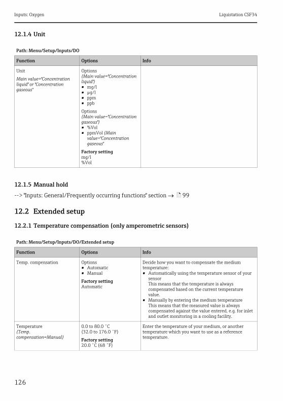
Inputs: Oxygen Liquistation CSF34
126
12.1.4 Unit
12.1.5 Manual hold
--> "Inputs: General/Frequently occurring functions" section ä 99
12.2 Extended setup
12.2.1 Temperature compensation (only amperometric sensors)
Path: Menu/Setup/Inputs/DO
Function Options Info
Unit
Main value="Concentration liquid" or "Concentration gaseous"
Options(Main value="Concentration liquid")• mg/l• μg/l• ppm• ppb
Options(Main value="Concentration gaseous")• %Vol• ppmVol (Main
value="Concentration gaseous"
Factory settingmg/l%Vol
Path: Menu/Setup/Inputs/DO/Extended setup
Function Options Info
Temp. compensation Options• Automatic• Manual
Factory settingAutomatic
Decide how you want to compensate the medium temperature:• Automatically using the temperature sensor of your
sensorThis means that the temperature is always compensated based on the current temperature value.
• Manually by entering the medium temperatureThis means that the measured value is always compensated against the value entered, e.g. for inlet and outlet monitoring in a cooling facility.
Temperature(Temp. compensation=Manual)
0.0 to 80.0 ˚C(32.0 to 176.0 ˚F)
Factory setting20.0 ˚C (68 ˚F)
Enter the temperature of your medium, or another temperature which you want to use as a reference temperature.

Liquistation CSF34 Inputs: Oxygen
127
12.2.2 Measured value formats
12.2.3 Medium compensation (in the process)
Path: Menu/Setup/Inputs/DO or Chlorine/Extended setup1)
1) In the case of chlorine, the sequence of the two menu functions is reversed
Function Options Info
Main value format Options• #.#• #.##• #.###• #
Factory setting#.##
Specify the number of decimal places for displaying the main measured value.
Temperature format Options• #.#• #.##
Factory setting#.#
Select how many decimal places should be used to display the temperature.
Path: Menu/Setup/Inputs/DO/Extended setup
Function Options Info
Medium pressure Options• Process pressure• Air pressure• Altitude
Factory settingAir pressure
Altitude
Medium pressure="Altitude"
-300 to 4000 m
Factory setting0 m
Enter the altitude or the average air pressure (mutually dependent values).If you specify the altitude, the average air pressure is calculated from the barometric altitude formula and vice versa.If you are compensating using the process pressure, enter the pressure in your process here. The pressure is then independent of the altitude.
Air pressureorProcess pressure
Medium pressure="Air pressure"500 to 1200 hPa
Medium pressure="Process pressure"500 to 9999 hPa
Factory setting1013 hPa
Salinity 0 to 40 g/kg
Factory setting0 g/kg
The influence of salt content on oxygen measurement is compensated with this function. Example: sea water measurement as per Copenhagen Standard (30 g/kg).
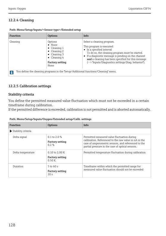
Inputs: Oxygen Liquistation CSF34
128
12.2.4 Cleaning
12.2.5 Calibration settings
Stability criteria
You define the permitted measured value fluctuation which must not be exceeded in a certain timeframe during calibration.If the permitted difference is exceeded, calibration is not permitted and is aborted automatically.
Path: Menu/Setup/Inputs/<Sensor type>/Extended setup
Function Options Info
Cleaning Options• None• Cleaning 1• Cleaning 2• Cleaning 3• Cleaning 4
Factory settingNone
Select a cleaning program.
This program is executed:• In a specified interval
To do so, the cleaning program must be started.• If a diagnostic message is pending on the channel
and a cleaning has been specified for this message (--> "Inputs/Diagnostics settings/Diag. behavior").
You define the cleaning programs in the "Setup/Additional functions/Cleaning" menu.
Path: Menu/Setup/Inputs/Oxygen/Extended setup/Calib. settings
Function Options Info
Stability criteria
Delta signal 0.1 to 2.0 %
Factory setting0.2 %
Permitted measured value fluctuation during calibration. Referenced to the raw value in nA in the case of amperometric sensors, and referenced to the partial pressure in the case of optical sensors.
Delta temperature 0.10 to 2.00 K
Factory setting0.50 K
Permitted temperature fluctuation during calibration
Duration 5 to 60 s
Factory setting20 s
Timeframe within which the permitted range for measured value fluctuation should not be exceeded

Liquistation CSF34 Inputs: Oxygen
129
Medium compensation (during calibration)
Calibration timer and calibration expiration date
--> "Inputs: General/Frequently occurring functions" section ä 99
12.2.6 Diagnostics settings
This menu branch is used for specifying warning limits, and for defining whether and how diagnostics tools should be used.The associated diagnostics code is displayed for every setting.
Slope
The (relative) slope characterizes the sensor condition. Decreasing values indicate electrolyte exhaustion. You can control when the electrolyte should be replaced by specifying limit values and the diagnostics messages these limit values trigger.
Path: Menu/Setup/Inputs/DO/Extended setup/Calib. settings
Function Options Info
Medium pressure Options• Process pressure• Air pressure• Altitude
Factory settingAir pressure
Altitude
Medium pressure="Altitude"
-300 to 4000 m
Factory setting0 m
Enter the altitude or the average air pressure (mutually dependent values).If you specify the altitude, the average air pressure is calculated from the barometric altitude formula and vice versa.If you are compensating using the process pressure, enter the pressure in your process here. The pressure is then independent of the altitude.
Air pressureorProcess pressure
Medium pressure="Air pressure"500 to 1200 hPa
Medium pressure="Process pressure"500 to 9999 hPa
Factory setting1013 hPa
Rel. hum. (air variable) 0 to 100 %
Factory setting100 %
Path: Menu/Setup/Inputs/DO/Extended setup/Diagnostics settings
Function Options Info
Slope 0.0 to 200.0 % Specify the limit values for slope monitoring in your sensor.

Inputs: Oxygen Liquistation CSF34
130
Delta slope (only amperometric sensors)
The device determines the difference in slope between the last calibration and the penultimate calibration, and issues a warning or an alarm depending on the setting configured. The difference is an indicator for the condition of the sensor. An increasing change indicates the formation of buildup on the sensor diaphragm or electrolyte contamination. Replace the diaphragm and electrolyte as specified in the instructions in the sensor operating manual.
Zero point (only amperometric sensors)
The zero point corresponds to the sensor signal that is measured in a medium in the absence of oxygen. You can calibrate the zero point in water that is free from oxygen or in high-purity nitrogen. This improves accuracy in the trace range.
Upper warning limit Factory setting140.0 %
Diagnostics code and associated message text:511 "Sensor calib."
Lower warning limit Factory setting60.0 %
Diagnostics code and associated message text:509 "Sensor calib."
Path: Menu/Setup/Inputs/DO/Extended setup/Diagnostics settings
Function Options Info
Delta slope 0.0 to 50.0 % Specify the limit values for monitoring the slope differential.
Function Options• On• Off
Factory settingOn
Warning limit Factory setting5.0 %
Diagnostics code and associated message text:518 "Sensor calib."
Path: Menu/Setup/Inputs/DO/Extended setup/Diagnostics settings
Function Options Info
Zero point 0.0 to 10.0 nA Specify the limit values for zero point monitoring in your sensor.
Warning limit Factory setting3.0 nA
Diagnostics code and associated message text:513 "Zero Warn"
Path: Menu/Setup/Inputs/DO/Extended setup/Diagnostics settings
Function Options Info
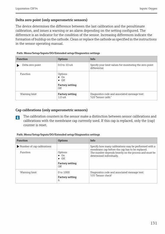
Liquistation CSF34 Inputs: Oxygen
131
Delta zero point (only amperometric sensors)
The device determines the difference between the last calibration and the penultimate calibration, and issues a warning or an alarm depending on the setting configured. The difference is an indicator for the condition of the sensor. Increasing differences indicate the formation of buildup on the cathode. Clean or replace the cathode as specified in the instructions in the sensor operating manual.
Cap calibrations (only amperometric sensors)
The calibration counters in the sensor make a distinction between sensor calibrations and calibrations with the membrane cap currently used. If this cap is replaced, only the (cap) counter is reset.
Path: Menu/Setup/Inputs/DO/Extended setup/Diagnostics settings
Function Options Info
Delta zero point 0.0 to 10 nA Specify your limit values for monitoring the zero point differential.
Function Options• On• Off
Factory settingOff
Warning limit Factory setting1.0 nA
Diagnostics code and associated message text:520 "Sensor calib."
Path: Menu/Setup/Inputs/DO/Extended setup/Diagnostics settings
Function Options Info
Number of cap calibrations Specify how many calibrations may be performed with a membrane cap before the cap has to be replaced.The number depends heavily on the process and must be determined individually.
Function Options• On• Off
Factory settingOff
Warning limit 0 to 1000
Factory setting6
Diagnostics code and associated message text:535 "Sensor check"
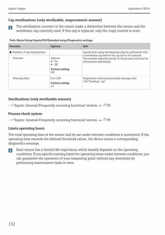
Inputs: Oxygen Liquistation CSF34
132
Cap sterilizations (only sterilizable, amperometric sensors)
The sterilization counters in the sensor make a distinction between the sensor and the membrane cap currently used. If this cap is replaced, only the (cap) counter is reset.
Sterilizations (only sterilizable sensors)
--> "Inputs: General/Frequently occurring functions" section ä 99
Process check system
--> "Inputs: General/Frequently occurring functions" section ä 99
Limits operating hours
The total operating time of the sensor and its use under extreme conditions is monitored. If the operating time exceeds the defined threshold values, the device issues a corresponding diagnostics message.
Each sensor has a limited life expectancy which heavily depends on the operating conditions. If you specify warning limits for operating times under extreme conditions, you can guarantee the operation of your measuring point without any downtime by performing maintenance tasks in time.
Path: Menu/Setup/Inputs/DO/Extended setup/Diagnostics settings
Function Options Info
Number of cap sterilizations Specify how many sterilizations may be performed with a membrane cap before the cap has to be replaced.The number depends heavily on the process and must be determined individually.
Function Options• On• Off
Factory settingOff
Warning limit 0 to 100
Factory setting25
Diagnostics code and associated message text:109 "Sterilizat. cap"

Liquistation CSF34 Inputs: Oxygen
133
Path: Menu/Setup/Inputs/DO/Extended setup/Diagnostics settings
Function Options Info
Limits operating hours
The range of adjustment for the operating hours alarm and warning limits is generally 1 to 50000 h.
Function Options• On• Off
Factory settingOff
OnThe operation of the sensor under extreme conditions is monitored, recorded in the sensor and diagnostics messages are displayed on the controller.OffNo diagnostics messages. However, the time the sensor operates under extreme conditions is recorded in the sensor and can be read in the sensor information in the diagnostics menu.
Operating time Total operating time of the sensor
Warning limit Factory setting10000 h
Diagnostics code and associated message text:199 "Operating time"
Operation < 5°C Only optical sensors
Warning limit Factory setting10000 h
Diagnostics code and associated message text:188 "Operating time"
Operation > 5°C only COS51D
Warning limit Factory setting10000 h
Diagnostics code and associated message text:189 "Operating time"
Operation > 25°C Only optical sensors
Warning limit Factory setting10000 h
Diagnostics code and associated message text:190 "Operating time"
Operation > 30°C only COS51D
Warning limit Factory setting10000 h
Diagnostics code and associated message text:191 "Operating time"
Operation > 40°C only COS22D, COS61D
Warning limit Factory setting10000 h
Diagnostics code and associated message text:192 "Operating time"
Operation > 80°C only COS22D
Warning limit Factory setting10000 h
Diagnostics code and associated message text:193 "Operating time"
(Operation above first specified nA value)
Only amperometric sensors, sensor-specific limit– COS22D: >15 nA– COS51D: >30 nA
Warning limit Factory setting10000 h
Diagnostics code and associated message text:183 "Operating time" (COS22D)184 "Operating time" (COS51D)
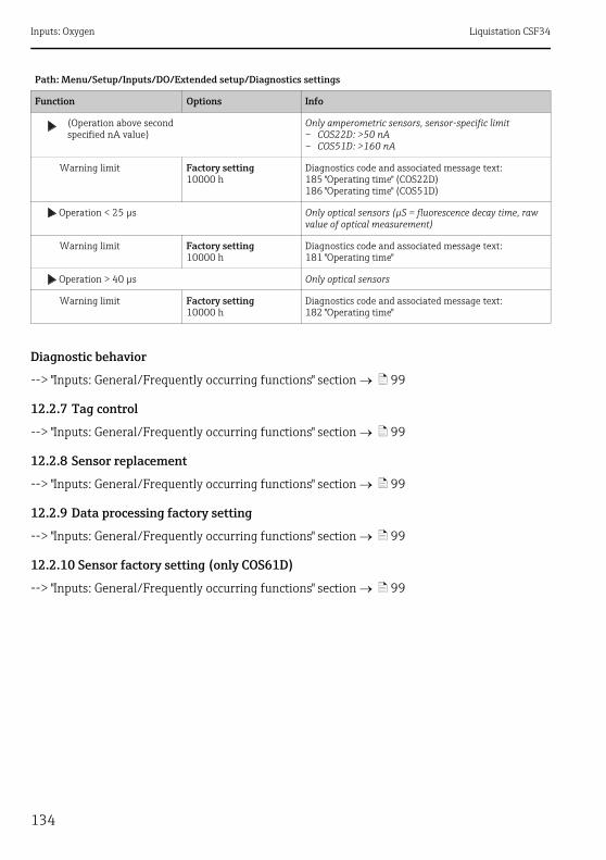
Inputs: Oxygen Liquistation CSF34
134
Diagnostic behavior
--> "Inputs: General/Frequently occurring functions" section ä 99
12.2.7 Tag control
--> "Inputs: General/Frequently occurring functions" section ä 99
12.2.8 Sensor replacement
--> "Inputs: General/Frequently occurring functions" section ä 99
12.2.9 Data processing factory setting
--> "Inputs: General/Frequently occurring functions" section ä 99
12.2.10 Sensor factory setting (only COS61D)
--> "Inputs: General/Frequently occurring functions" section ä 99
(Operation above second specified nA value)
Only amperometric sensors, sensor-specific limit– COS22D: >50 nA– COS51D: >160 nA
Warning limit Factory setting10000 h
Diagnostics code and associated message text:185 "Operating time" (COS22D)186 "Operating time" (COS51D)
Operation < 25 μs Only optical sensors (μS = fluorescence decay time, raw value of optical measurement)
Warning limit Factory setting10000 h
Diagnostics code and associated message text:181 "Operating time"
Operation > 40 μs Only optical sensors
Warning limit Factory setting10000 h
Diagnostics code and associated message text:182 "Operating time"
Path: Menu/Setup/Inputs/DO/Extended setup/Diagnostics settings
Function Options Info

Liquistation CSF34 Inputs: Chlorine
135
13 Inputs: Chlorine
13.1 Basic settings
13.1.1 Sensor identification
13.1.2 Main value
13.1.3 Damping
--> "Inputs: General/Frequently occurring functions" section ä 99
13.1.4 Manual hold
--> "Inputs: General/Frequently occurring functions" section ä 99
Path: Menu/Setup/Inputs/<Sensor type>
Function Options Info
Channel Options• On• Off
Factory settingOn
OnThe channel display is switched on in the measuring modeOffThe channel is not displayed in the measuring mode, regardless of whether a sensor is connected or not.
Sensor type Read only(Only available if a sensor is connected)
Connected sensor type
Order code Order code of the connected sensor
Path: Menu/Setup/Inputs/Chlorine
Function Options Info
Main value Options• Concentration• Sensor current (nA)
Factory settingConcentration
Decide how you want to display the main value.
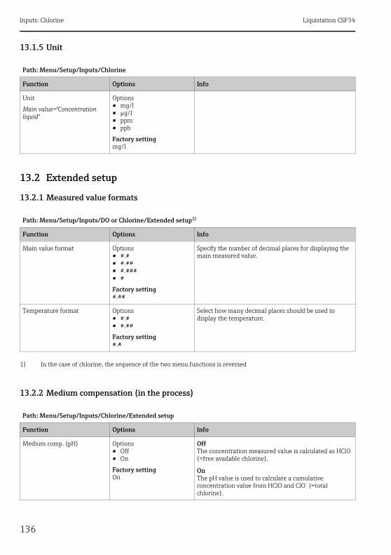
Inputs: Chlorine Liquistation CSF34
136
13.1.5 Unit
13.2 Extended setup
13.2.1 Measured value formats
13.2.2 Medium compensation (in the process)
Path: Menu/Setup/Inputs/Chlorine
Function Options Info
Unit
Main value="Concentration liquid"
Options• mg/l• μg/l• ppm• ppb
Factory settingmg/l
Path: Menu/Setup/Inputs/DO or Chlorine/Extended setup1)
1) In the case of chlorine, the sequence of the two menu functions is reversed
Function Options Info
Main value format Options• #.#• #.##• #.###• #
Factory setting#.##
Specify the number of decimal places for displaying the main measured value.
Temperature format Options• #.#• #.##
Factory setting#.#
Select how many decimal places should be used to display the temperature.
Path: Menu/Setup/Inputs/Chlorine/Extended setup
Function Options Info
Medium comp. (pH) Options• Off• On
Factory settingOn
OffThe concentration measured value is calculated as HClO (=free available chlorine).
OnThe pH value is used to calculate a cumulative concentration value from HClO and ClO- (=total chlorine).

Liquistation CSF34 Inputs: Chlorine
137
13.2.3 Cleaning
--> "Inputs: General/Frequently occurring functions" section ä 99
13.2.4 Calibration settings
Calibration timer and calibration expiration date
--> "Inputs: General/Frequently occurring functions" section ä 99
Stability criteria
You define the permitted measured value fluctuation which must not be exceeded in a certain timeframe during calibration.If the permitted difference is exceeded, calibration is not permitted and is aborted automatically.
Mode
Medium comp. (pH)="On"
Options• Fixed value• Measured value
Factory settingFixed value
Decide whether you want to specify a fixed pH value for calculating the total chlorine or whether the measured value of a pH sensor attached to another input should be used.
Fixed pH
Mode="Fixed value"
4.00 to 9.00 pH
Factory setting7.20 pH
Useful for media with a constant pH value
Enter the pH value of your medium which you determined with a reference measurement.
Associated pH-sensor
Mode="Measured value"
Select the pH sensor
Factory settingNone
Preferred method for media with varying pH values
Select the sensor input with the connected pH sensor. The measured value of the sensor is then continuously used to calculate the total chlorine.
Temp. compensation Options• Off• Automatic• Manual
Factory settingAutomatic
Decide whether and how you want to compensate the medium temperature:• No compensation• Automatically using the temperature sensor of your
sensor• Manually by entering the medium temperature
Medium temperature(Temp. compensation=Manual)
-5.0 to 50.0 ˚C(23.0 to 122.0 ˚F)
Factory setting20.0 ˚C (68 ˚F)
Enter the temperature of your medium.
Path: Menu/Setup/Inputs/Chlorine/Extended setup
Function Options Info
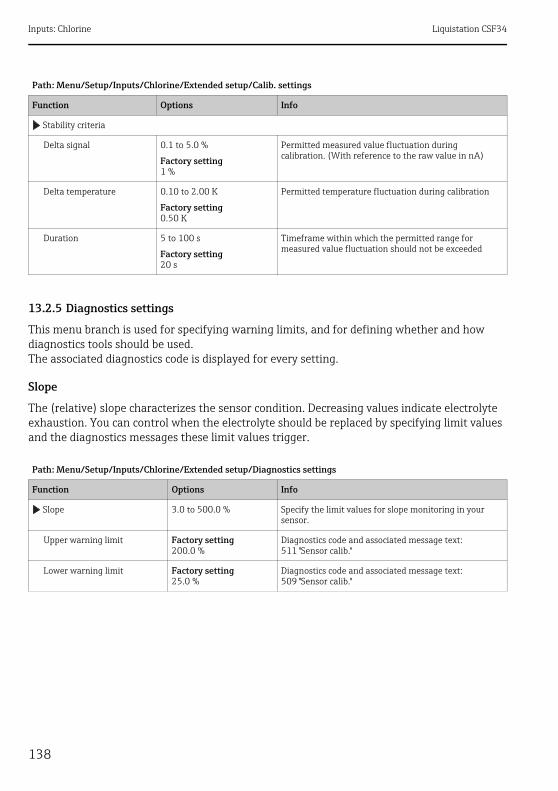
Inputs: Chlorine Liquistation CSF34
138
13.2.5 Diagnostics settings
This menu branch is used for specifying warning limits, and for defining whether and how diagnostics tools should be used.The associated diagnostics code is displayed for every setting.
Slope
The (relative) slope characterizes the sensor condition. Decreasing values indicate electrolyte exhaustion. You can control when the electrolyte should be replaced by specifying limit values and the diagnostics messages these limit values trigger.
Path: Menu/Setup/Inputs/Chlorine/Extended setup/Calib. settings
Function Options Info
Stability criteria
Delta signal 0.1 to 5.0 %
Factory setting1 %
Permitted measured value fluctuation during calibration. (With reference to the raw value in nA)
Delta temperature 0.10 to 2.00 K
Factory setting0.50 K
Permitted temperature fluctuation during calibration
Duration 5 to 100 s
Factory setting20 s
Timeframe within which the permitted range for measured value fluctuation should not be exceeded
Path: Menu/Setup/Inputs/Chlorine/Extended setup/Diagnostics settings
Function Options Info
Slope 3.0 to 500.0 % Specify the limit values for slope monitoring in your sensor.
Upper warning limit Factory setting200.0 %
Diagnostics code and associated message text:511 "Sensor calib."
Lower warning limit Factory setting25.0 %
Diagnostics code and associated message text:509 "Sensor calib."

Liquistation CSF34 Inputs: Chlorine
139
Delta slope
The device determines the difference in slope between the last calibration and the penultimate calibration, and issues a warning or an alarm depending on the setting configured. The difference is an indicator for the condition of the sensor. An increasing change indicates the formation of buildup on the sensor diaphragm or electrolyte contamination. Replace the diaphragm and electrolyte as specified in the instructions in the sensor operating manual.
Zero point
The zero point corresponds to the sensor signal that is measured in a medium in the absence of chlorine. You can calibrate the zero point in water that is free from chlorine. This improves accuracy in the trace range.
Path: Menu/Setup/Inputs/Chlorine/Extended setup/Diagnostics settings
Function Options Info
Delta slope 1 to 15 % Specify the limit values for monitoring the slope differential.
Function Options• On• Off
Factory settingOff
Warning limit Factory setting5 %
Diagnostics code and associated message text:518 "Sensor calib."
Path: Menu/Setup/Inputs/Chlorine/Extended setup/Diagnostics settings
Function Options Info
Zero point 0.0 to 3.2 nA Specify the limit values for zero point monitoring in your sensor.
Warning limit Factory setting2.0 nA
Diagnostics code and associated message text:513 "Zero Warn"
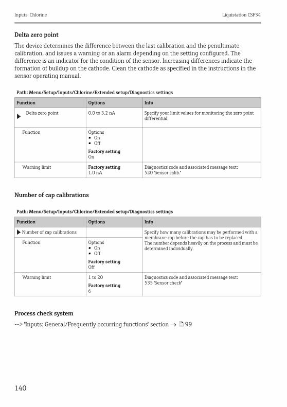
Inputs: Chlorine Liquistation CSF34
140
Delta zero point
The device determines the difference between the last calibration and the penultimate calibration, and issues a warning or an alarm depending on the setting configured. The difference is an indicator for the condition of the sensor. Increasing differences indicate the formation of buildup on the cathode. Clean the cathode as specified in the instructions in the sensor operating manual.
Number of cap calibrations
Process check system
--> "Inputs: General/Frequently occurring functions" section ä 99
Path: Menu/Setup/Inputs/Chlorine/Extended setup/Diagnostics settings
Function Options Info
Delta zero point 0.0 to 3.2 nA Specify your limit values for monitoring the zero point differential.
Function Options• On• Off
Factory settingOn
Warning limit Factory setting1.0 nA
Diagnostics code and associated message text:520 "Sensor calib."
Path: Menu/Setup/Inputs/Chlorine/Extended setup/Diagnostics settings
Function Options Info
Number of cap calibrations Specify how many calibrations may be performed with a membrane cap before the cap has to be replaced.The number depends heavily on the process and must be determined individually.
Function Options• On• Off
Factory settingOff
Warning limit 1 to 20
Factory setting6
Diagnostics code and associated message text:535 "Sensor check"

Liquistation CSF34 Inputs: Chlorine
141
Limits operating hours
The total operating time of the sensor and its use under extreme conditions is monitored. If the operating time exceeds the defined threshold values, the device issues a corresponding diagnostics message.
Each sensor has a limited life expectancy which heavily depends on the operating conditions. If you specify warning limits for operating times under extreme conditions, you can guarantee the operation of your measuring point without any downtime by performing maintenance tasks in time.
Path: Menu/Setup/Inputs/Chlorine/Extended setup/Diagnostics settings
Function Options Info
Limits operating hours
The range of adjustment for the operating hours alarm and warning limits is generally 1 to 100000 h.
Function Options• On• Off
Factory settingOff
OnThe operation of the sensor under extreme conditions is monitored, recorded in the sensor and diagnostics messages are displayed on the controller.OffNo diagnostics messages. However, the time the sensor operates under extreme conditions is recorded in the sensor and can be read in the sensor information in the diagnostics menu.
Operating time Total operating time of the sensor
Warning limit Factory setting10000 h
Diagnostics code and associated message text:199 "Operating time"
Operation > 15°C
Warning limit Factory setting10000 h
Diagnostics code and associated message text:178 "Operating time"
Operation > 30°C
Warning limit Factory setting10000 h
Diagnostics code and associated message text:191 "Operating time"
Operation > 20 nA
Warning limit Factory setting10000 h
Diagnostics code and associated message text:177 "Operating time"
Operation > 100 nA
Warning limit Factory setting10000 h
Diagnostics code and associated message text:176 "Operating time"

Inputs: Chlorine Liquistation CSF34
142
Electrolyte counter
The electrolyte consumption is calculated on the basis of the amount of charge that penetrates the sensor diaphragm.
The following applies for the sensor CCS142D:Half the chloride would be consumed and the entire dihydrogen phosphate would be converted to monohydrogen phosphate in an electrolyte filling (4 ml) at 20 000 000 μAs (=20 As). This would render the electrolyte and the sensor unusable.
With a view to predictive maintenance, you should replace the electrolyte at 10 000 000 μAs, and preferably at 5 000 000 μAs. 25%-50% of the dihydrogen phosphate is then consumed.The calculation presumes that the buffer of the electrolyte is only changed by the electrochemical conversion of hypochlorous acid. It does not take into account the penetration of acids or bases into the sensor.Depending on the application it can be necessary to change the electrolyte before a charge of 5 As is reached.
Diagnostic behavior
--> "Inputs: General/Frequently occurring functions" section ä 99
13.2.6 Tag control
--> "Inputs: General/Frequently occurring functions" section ä 99
13.2.7 Sensor replacement
--> "Inputs: General/Frequently occurring functions" section ä 99
13.2.8 Data processing factory setting
--> "Inputs: General/Frequently occurring functions" section ä 99
Path: Menu/Setup/Inputs/Chlorine/Extended setup/Diagnostics settings
Function Options Info
Electrolyte counter 0 to 2000000 μAs
Function Options• On• Off
Factory settingOn
Warning limit Factory setting1000000 μAs
Diagnostics code and associated message text:534 "Sensor calib."

Liquistation CSF34 Inputs: Turbidity and solids
143
14 Inputs: Turbidity and solids
14.1 Basic settings
14.1.1 Sensor identification
14.1.2 Application
The sensor is precalibrated on leaving the factory. As such, it can be used in a wide range of applications (e.g. clear water measurement) without the need for additional calibration. The factory calibration is based on a three-point calibration of a reference sample.The factory calibration cannot be deleted and can be retrieved at any time. All other calibrations -performed as customer calibrations - are referenced to this factory calibration.
Calibration data records are saved under an individual name. You can add your own data records during each calibration. These are then available for selection under "Application".
14.1.3 Damping
--> "Inputs: General/Frequently occurring functions" section ä 99
Path: Menu/Setup/Inputs/<Sensor type>
Function Options Info
Channel Options• On• Off
Factory settingOn
OnThe channel display is switched on in the measuring modeOffThe channel is not displayed in the measuring mode, regardless of whether a sensor is connected or not.
Sensor type Read only(Only available if a sensor is connected)
Connected sensor type
Order code Order code of the connected sensor
Path: Menu/Setup/Inputs/Turbidity
Function Options Info
Application type Options• Clear water• Solid
Factory settingClear water
Preselection for saved calibration data records
Application Depends on the sensor Select a saved calibration data record
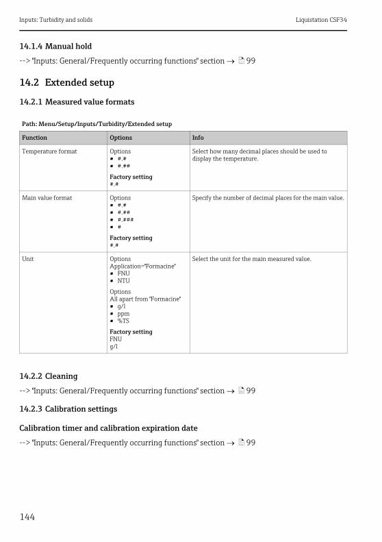
Inputs: Turbidity and solids Liquistation CSF34
144
14.1.4 Manual hold
--> "Inputs: General/Frequently occurring functions" section ä 99
14.2 Extended setup
14.2.1 Measured value formats
14.2.2 Cleaning
--> "Inputs: General/Frequently occurring functions" section ä 99
14.2.3 Calibration settings
Calibration timer and calibration expiration date
--> "Inputs: General/Frequently occurring functions" section ä 99
Path: Menu/Setup/Inputs/Turbidity/Extended setup
Function Options Info
Temperature format Options• #.#• #.##
Factory setting#.#
Select how many decimal places should be used to display the temperature.
Main value format Options• #.#• #.##• #.###• #
Factory setting#.#
Specify the number of decimal places for the main value.
Unit OptionsApplication="Formacine"• FNU• NTU
OptionsAll apart from "Formacine"• g/l• ppm• %TS
Factory settingFNUg/l
Select the unit for the main measured value.
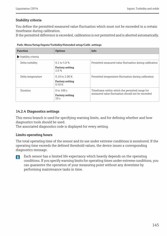
Liquistation CSF34 Inputs: Turbidity and solids
145
Stability criteria
You define the permitted measured value fluctuation which must not be exceeded in a certain timeframe during calibration.If the permitted difference is exceeded, calibration is not permitted and is aborted automatically.
14.2.4 Diagnostics settings
This menu branch is used for specifying warning limits, and for defining whether and how diagnostics tools should be used.The associated diagnostics code is displayed for every setting.
Limits operating hours
The total operating time of the sensor and its use under extreme conditions is monitored. If the operating time exceeds the defined threshold values, the device issues a corresponding diagnostics message.
Each sensor has a limited life expectancy which heavily depends on the operating conditions. If you specify warning limits for operating times under extreme conditions, you can guarantee the operation of your measuring point without any downtime by performing maintenance tasks in time.
Path: Menu/Setup/Inputs/Turbidity/Extended setup/Calib. settings
Function Options Info
Stability criteria
Delta turbidity 0.1 to 5.0 %
Factory setting2.0 %
Permitted measured value fluctuation during calibration
Delta temperature 0.10 to 2.00 K
Factory setting0.50 K
Permitted temperature fluctuation during calibration
Duration 0 to 100 s
Factory setting20 s
Timeframe within which the permitted range for measured value fluctuation should not be exceeded
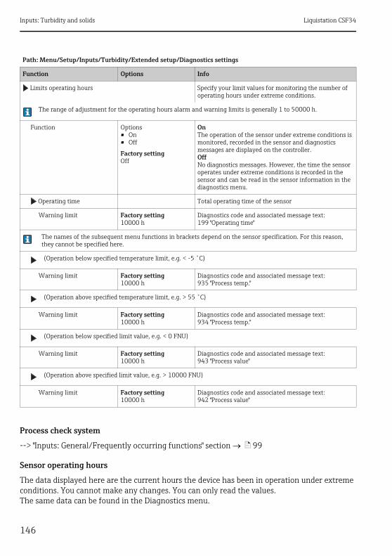
Inputs: Turbidity and solids Liquistation CSF34
146
Process check system
--> "Inputs: General/Frequently occurring functions" section ä 99
Sensor operating hours
The data displayed here are the current hours the device has been in operation under extreme conditions. You cannot make any changes. You can only read the values.The same data can be found in the Diagnostics menu.
Path: Menu/Setup/Inputs/Turbidity/Extended setup/Diagnostics settings
Function Options Info
Limits operating hours Specify your limit values for monitoring the number of operating hours under extreme conditions.
The range of adjustment for the operating hours alarm and warning limits is generally 1 to 50000 h.
Function Options• On• Off
Factory settingOff
OnThe operation of the sensor under extreme conditions is monitored, recorded in the sensor and diagnostics messages are displayed on the controller.OffNo diagnostics messages. However, the time the sensor operates under extreme conditions is recorded in the sensor and can be read in the sensor information in the diagnostics menu.
Operating time Total operating time of the sensor
Warning limit Factory setting10000 h
Diagnostics code and associated message text:199 "Operating time"
The names of the subsequent menu functions in brackets depend on the sensor specification. For this reason, they cannot be specified here.
(Operation below specified temperature limit, e.g. < -5 ˚C)
Warning limit Factory setting10000 h
Diagnostics code and associated message text:935 "Process temp."
(Operation above specified temperature limit, e.g. > 55 ˚C)
Warning limit Factory setting10000 h
Diagnostics code and associated message text:934 "Process temp."
(Operation below specified limit value, e.g. < 0 FNU)
Warning limit Factory setting10000 h
Diagnostics code and associated message text:943 "Process value"
(Operation above specified limit value, e.g. > 10000 FNU)
Warning limit Factory setting10000 h
Diagnostics code and associated message text:942 "Process value"

Liquistation CSF34 Inputs: Turbidity and solids
147
Diagnostic behavior
--> "Inputs: General/Frequently occurring functions" section ä 99
14.2.5 Tag control
--> "Inputs: General/Frequently occurring functions" section ä 99
14.2.6 Sensor replacement
--> "Inputs: General/Frequently occurring functions" section ä 99
14.2.7 Data processing factory setting
--> "Inputs: General/Frequently occurring functions" section ä 99
14.2.8 Sensor factory setting
--> "Inputs: General/Frequently occurring functions" section ä 99

Inputs: SAC Liquistation CSF34
148
15 Inputs: SAC
15.1 Basic settings
15.1.1 Sensor identification
15.1.2 Application
Calibration data records are saved under an individual name in the sensor. A new sensor is calibrated at the factory and thus already has appropriate data records. You can add your own data records during each calibration. These are then available for selection under "Application".
15.1.3 Damping
--> "Inputs: General/Frequently occurring functions" section ä 99
Path: Menu/Setup/Inputs/<Sensor type>
Function Options Info
Channel Options• On• Off
Factory settingOn
OnThe channel display is switched on in the measuring modeOffThe channel is not displayed in the measuring mode, regardless of whether a sensor is connected or not.
Sensor type Read only(Only available if a sensor is connected)
Connected sensor type
Order code Order code of the connected sensor
Path: Menu/Setup/Inputs/SAC
Function Options Info
Basic application Options• SAC• Transm.• Absorption• COD• TOC• DOC• BOD
Factory settingSAC
Preselection for saved calibration data records
Application Options• Factory calib.• 5 other data records
Factory settingFactory calib.
Select a saved calibration data record
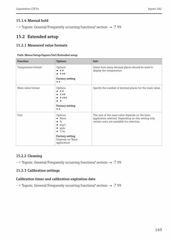
Liquistation CSF34 Inputs: SAC
149
15.1.4 Manual hold
--> "Inputs: General/Frequently occurring functions" section ä 99
15.2 Extended setup
15.2.1 Measured value formats
15.2.2 Cleaning
--> "Inputs: General/Frequently occurring functions" section ä 99
15.2.3 Calibration settings
Calibration timer and calibration expiration date
--> "Inputs: General/Frequently occurring functions" section ä 99
Path: Menu/Setup/Inputs/SAC/Extended setup
Function Options Info
Temperature format Options• #.#• #.##
Factory setting#.#
Select how many decimal places should be used to display the temperature.
Main value format Options• #.#• #.##• #.###• #
Factory setting#.#
Specify the number of decimal places for the main value.
Unit Options• None• %• mg/l• ppm• 1/m
Factory settingDepends on "Basic application"
The unit of the main value depends on the basic application selected. Depending on this setting only certain units are available for selection.
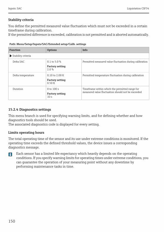
Inputs: SAC Liquistation CSF34
150
Stability criteria
You define the permitted measured value fluctuation which must not be exceeded in a certain timeframe during calibration.If the permitted difference is exceeded, calibration is not permitted and is aborted automatically.
15.2.4 Diagnostics settings
This menu branch is used for specifying warning limits, and for defining whether and how diagnostics tools should be used.The associated diagnostics code is displayed for every setting.
Limits operating hours
The total operating time of the sensor and its use under extreme conditions is monitored. If the operating time exceeds the defined threshold values, the device issues a corresponding diagnostics message.
Each sensor has a limited life expectancy which heavily depends on the operating conditions. If you specify warning limits for operating times under extreme conditions, you can guarantee the operation of your measuring point without any downtime by performing maintenance tasks in time.
Path: Menu/Setup/Inputs/SAC/Extended setup/Calib. settings
Function Options Info
Stability criteria
Delta SAC 0.1 to 5.0 %
Factory setting2.0 %
Permitted measured value fluctuation during calibration
Delta temperature 0.10 to 2.00 K
Factory setting0.50 K
Permitted temperature fluctuation during calibration
Duration 0 to 100 s
Factory setting10 s
Timeframe within which the permitted range for measured value fluctuation should not be exceeded
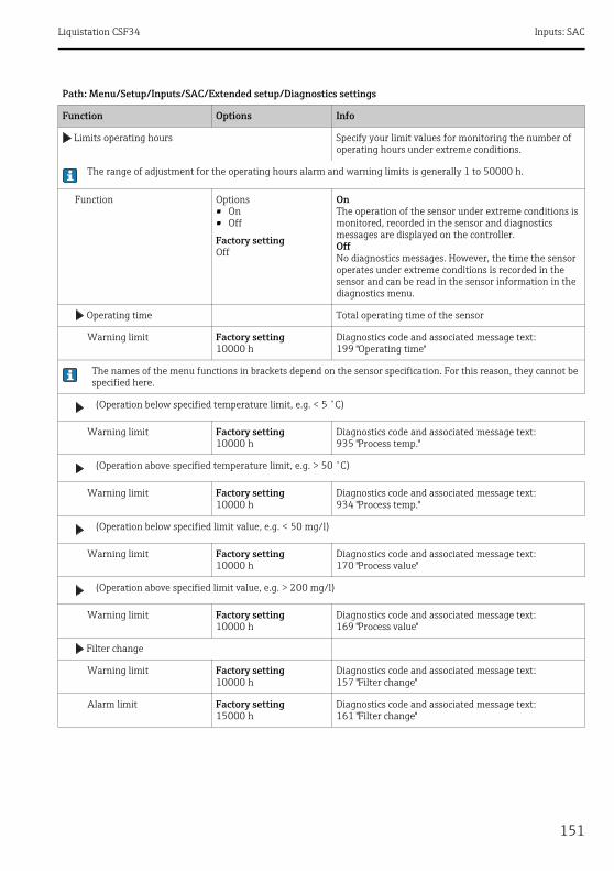
Liquistation CSF34 Inputs: SAC
151
Path: Menu/Setup/Inputs/SAC/Extended setup/Diagnostics settings
Function Options Info
Limits operating hours Specify your limit values for monitoring the number of operating hours under extreme conditions.
The range of adjustment for the operating hours alarm and warning limits is generally 1 to 50000 h.
Function Options• On• Off
Factory settingOff
OnThe operation of the sensor under extreme conditions is monitored, recorded in the sensor and diagnostics messages are displayed on the controller.OffNo diagnostics messages. However, the time the sensor operates under extreme conditions is recorded in the sensor and can be read in the sensor information in the diagnostics menu.
Operating time Total operating time of the sensor
Warning limit Factory setting10000 h
Diagnostics code and associated message text:199 "Operating time"
The names of the menu functions in brackets depend on the sensor specification. For this reason, they cannot be specified here.
(Operation below specified temperature limit, e.g. < 5 ˚C)
Warning limit Factory setting10000 h
Diagnostics code and associated message text:935 "Process temp."
(Operation above specified temperature limit, e.g. > 50 ˚C)
Warning limit Factory setting10000 h
Diagnostics code and associated message text:934 "Process temp."
(Operation below specified limit value, e.g. < 50 mg/l)
Warning limit Factory setting10000 h
Diagnostics code and associated message text:170 "Process value"
(Operation above specified limit value, e.g. > 200 mg/l)
Warning limit Factory setting10000 h
Diagnostics code and associated message text:169 "Process value"
Filter change
Warning limit Factory setting10000 h
Diagnostics code and associated message text:157 "Filter change"
Alarm limit Factory setting15000 h
Diagnostics code and associated message text:161 "Filter change"
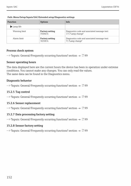
Inputs: SAC Liquistation CSF34
152
Process check system
--> "Inputs: General/Frequently occurring functions" section ä 99
Sensor operating hours
The data displayed here are the current hours the device has been in operation under extreme conditions. You cannot make any changes. You can only read the values.The same data can be found in the Diagnostics menu.
Diagnostic behavior
--> "Inputs: General/Frequently occurring functions" section ä 99
15.2.5 Tag control
--> "Inputs: General/Frequently occurring functions" section ä 99
15.2.6 Sensor replacement
--> "Inputs: General/Frequently occurring functions" section ä 99
15.2.7 Data processing factory setting
--> "Inputs: General/Frequently occurring functions" section ä 99
15.2.8 Sensor factory setting
--> "Inputs: General/Frequently occurring functions" section ä 99
Lamp life
Warning limit Factory setting35040 h
Diagnostics code and associated message text:171 "Lamp change"
Alarm limit Factory setting36500 h
Diagnostics code and associated message text:71 "Lamp change"
Path: Menu/Setup/Inputs/SAC/Extended setup/Diagnostics settings
Function Options Info
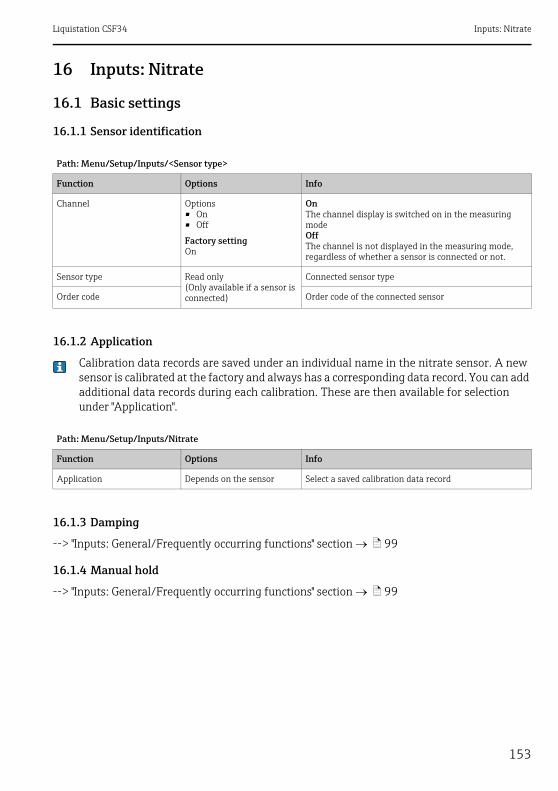
Liquistation CSF34 Inputs: Nitrate
153
16 Inputs: Nitrate
16.1 Basic settings
16.1.1 Sensor identification
16.1.2 Application
Calibration data records are saved under an individual name in the nitrate sensor. A new sensor is calibrated at the factory and always has a corresponding data record. You can add additional data records during each calibration. These are then available for selection under "Application".
16.1.3 Damping
--> "Inputs: General/Frequently occurring functions" section ä 99
16.1.4 Manual hold
--> "Inputs: General/Frequently occurring functions" section ä 99
Path: Menu/Setup/Inputs/<Sensor type>
Function Options Info
Channel Options• On• Off
Factory settingOn
OnThe channel display is switched on in the measuring modeOffThe channel is not displayed in the measuring mode, regardless of whether a sensor is connected or not.
Sensor type Read only(Only available if a sensor is connected)
Connected sensor type
Order code Order code of the connected sensor
Path: Menu/Setup/Inputs/Nitrate
Function Options Info
Application Depends on the sensor Select a saved calibration data record
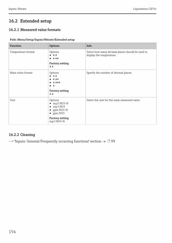
Inputs: Nitrate Liquistation CSF34
154
16.2 Extended setup
16.2.1 Measured value formats
16.2.2 Cleaning
--> "Inputs: General/Frequently occurring functions" section ä 99
Path: Menu/Setup/Inputs/Nitrate/Extended setup
Function Options Info
Temperature format Options• #.#• #.##
Factory setting#.#
Select how many decimal places should be used to display the temperature.
Main value format Options• #.#• #.##• #.###• #
Factory setting#.#
Specify the number of decimal places.
Unit Options• mg/l NO3-N• mg/l NO3• ppm NO3-N• ppm NO3
Factory settingmg/l NO3-N
Select the unit for the main measured value.
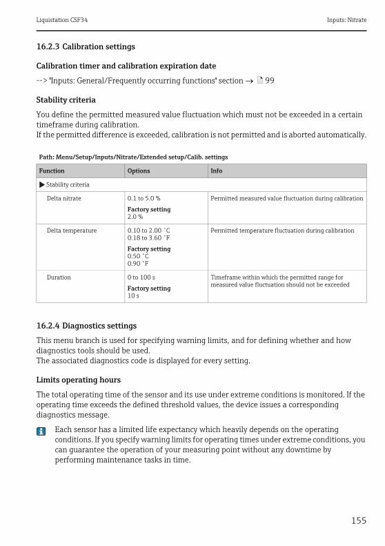
Liquistation CSF34 Inputs: Nitrate
155
16.2.3 Calibration settings
Calibration timer and calibration expiration date
--> "Inputs: General/Frequently occurring functions" section ä 99
Stability criteria
You define the permitted measured value fluctuation which must not be exceeded in a certain timeframe during calibration.If the permitted difference is exceeded, calibration is not permitted and is aborted automatically.
16.2.4 Diagnostics settings
This menu branch is used for specifying warning limits, and for defining whether and how diagnostics tools should be used.The associated diagnostics code is displayed for every setting.
Limits operating hours
The total operating time of the sensor and its use under extreme conditions is monitored. If the operating time exceeds the defined threshold values, the device issues a corresponding diagnostics message.
Each sensor has a limited life expectancy which heavily depends on the operating conditions. If you specify warning limits for operating times under extreme conditions, you can guarantee the operation of your measuring point without any downtime by performing maintenance tasks in time.
Path: Menu/Setup/Inputs/Nitrate/Extended setup/Calib. settings
Function Options Info
Stability criteria
Delta nitrate 0.1 to 5.0 %
Factory setting2.0 %
Permitted measured value fluctuation during calibration
Delta temperature 0.10 to 2.00 ˚C0.18 to 3.60 ˚F
Factory setting0.50 ˚C0.90 ˚F
Permitted temperature fluctuation during calibration
Duration 0 to 100 s
Factory setting10 s
Timeframe within which the permitted range for measured value fluctuation should not be exceeded
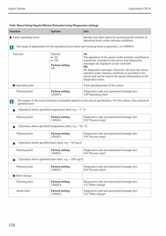
Inputs: Nitrate Liquistation CSF34
156
Path: Menu/Setup/Inputs/Nitrate/Extended setup/Diagnostics settings
Function Options Info
Limits operating hours Specify your limit values for monitoring the number of operating hours under extreme conditions.
The range of adjustment for the operating hours alarm and warning limits is generally 1 to 50000 h.
Function Options• On• Off
Factory settingOff
OnThe operation of the sensor under extreme conditions is monitored, recorded in the sensor and diagnostics messages are displayed on the controller.OffNo diagnostics messages. However, the time the sensor operates under extreme conditions is recorded in the sensor and can be read in the sensor information in the diagnostics menu.
Operating time Total operating time of the sensor
Warning limit Factory setting10000 h
Diagnostics code and associated message text:199 "Operating time"
The names of the menu functions in brackets depend on the sensor specification. For this reason, they cannot be specified here.
(Operation below specified temperature limit, e.g. < 5 ˚C)
Warning limit Factory setting10000 h
Diagnostics code and associated message text:935 "Process temp."
(Operation above specified temperature limit, e.g. > 50 ˚C)
Warning limit Factory setting10000 h
Diagnostics code and associated message text:934 "Process temp."
(Operation below specified limit value, e.g. < 50 mg/l)
Warning limit Factory setting10000 h
Diagnostics code and associated message text:943 "Process value"
(Operation above specified limit value, e.g. > 200 mg/l)
Warning limit Factory setting10000 h
Diagnostics code and associated message text:942 "Process value"
Filter change
Warning limit Factory setting10000 h
Diagnostics code and associated message text:157 "Filter change"
Alarm limit Factory setting15000 h
Diagnostics code and associated message text:161 "Filter change"
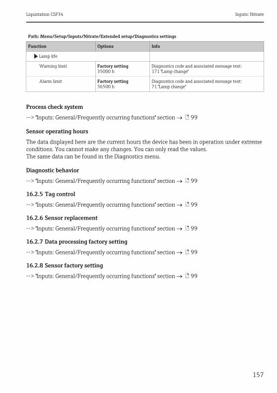
Liquistation CSF34 Inputs: Nitrate
157
Process check system
--> "Inputs: General/Frequently occurring functions" section ä 99
Sensor operating hours
The data displayed here are the current hours the device has been in operation under extreme conditions. You cannot make any changes. You can only read the values.The same data can be found in the Diagnostics menu.
Diagnostic behavior
--> "Inputs: General/Frequently occurring functions" section ä 99
16.2.5 Tag control
--> "Inputs: General/Frequently occurring functions" section ä 99
16.2.6 Sensor replacement
--> "Inputs: General/Frequently occurring functions" section ä 99
16.2.7 Data processing factory setting
--> "Inputs: General/Frequently occurring functions" section ä 99
16.2.8 Sensor factory setting
--> "Inputs: General/Frequently occurring functions" section ä 99
Lamp life
Warning limit Factory setting35000 h
Diagnostics code and associated message text:171 "Lamp change"
Alarm limit Factory setting36500 h
Diagnostics code and associated message text:71 "Lamp change"
Path: Menu/Setup/Inputs/Nitrate/Extended setup/Diagnostics settings
Function Options Info
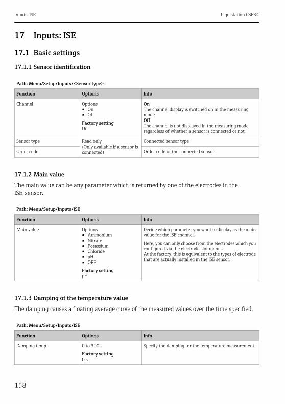
Inputs: ISE Liquistation CSF34
158
17 Inputs: ISE
17.1 Basic settings
17.1.1 Sensor identification
17.1.2 Main value
The main value can be any parameter which is returned by one of the electrodes in the ISE-sensor.
17.1.3 Damping of the temperature value
The damping causes a floating average curve of the measured values over the time specified.
Path: Menu/Setup/Inputs/<Sensor type>
Function Options Info
Channel Options• On• Off
Factory settingOn
OnThe channel display is switched on in the measuring modeOffThe channel is not displayed in the measuring mode, regardless of whether a sensor is connected or not.
Sensor type Read only(Only available if a sensor is connected)
Connected sensor type
Order code Order code of the connected sensor
Path: Menu/Setup/Inputs/ISE
Function Options Info
Main value Options• Ammonium• Nitrate• Potassium• Chloride• pH• ORP
Factory settingpH
Decide which parameter you want to display as the main value for the ISE channel.
Here, you can only choose from the electrodes which you configured via the electrode slot menus.At the factory, this is equivalent to the types of electrode that are actually installed in the ISE sensor.
Path: Menu/Setup/Inputs/ISE
Function Options Info
Damping temp. 0 to 300 s
Factory setting0 s
Specify the damping for the temperature measurement.
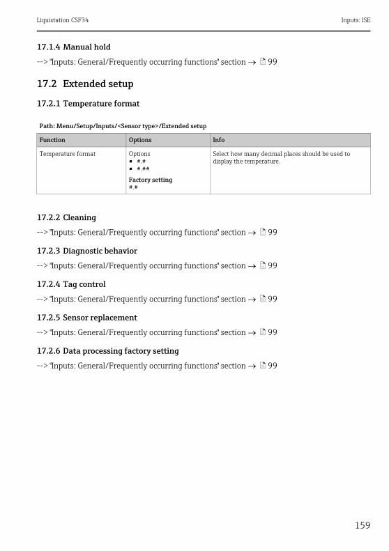
Liquistation CSF34 Inputs: ISE
159
17.1.4 Manual hold
--> "Inputs: General/Frequently occurring functions" section ä 99
17.2 Extended setup
17.2.1 Temperature format
17.2.2 Cleaning
--> "Inputs: General/Frequently occurring functions" section ä 99
17.2.3 Diagnostic behavior
--> "Inputs: General/Frequently occurring functions" section ä 99
17.2.4 Tag control
--> "Inputs: General/Frequently occurring functions" section ä 99
17.2.5 Sensor replacement
--> "Inputs: General/Frequently occurring functions" section ä 99
17.2.6 Data processing factory setting
--> "Inputs: General/Frequently occurring functions" section ä 99
Path: Menu/Setup/Inputs/<Sensor type>/Extended setup
Function Options Info
Temperature format Options• #.#• #.##
Factory setting#.#
Select how many decimal places should be used to display the temperature.

Inputs: ISE Liquistation CSF34
160
17.3 Electrode slot menus
17.3.1 Electrode slot
A CAS40D sensor has 4 electrode slots in total. Consequently, each of these slots has its own menu.
Make settings:‣ Define the parameter for the slot (only slots 2-4).
The 1st slot is always designated to the pH electrode. It is not possible to select another parameter for this slot.
‣ You can complete and assign the other 3 slots as you prefer.‣ Specify the measured variable that should be output. No options can be selected for pH
which is why the "Measured variable" function is not available for this parameter.
NOTICEIncorrect assignment between the electrode (hardware) and the software menuUnreliable measured values and faults in the measuring point can occur‣ When assigning the slot in the software, make sure it matches the assignment in the sensor.‣ Example: You have connected the ammonium electrode to cable no. 2 in the sensor. Then
configure the ammonium parameter in the "Slot 2:1 (ISE)" software menu.
17.3.2 Damping
The damping causes a floating average curve of the measured values over the time specified.
Options displayed for "Measured variable" with the following parameters:
pH Ammonium Nitrate Potassium Chloride
- • NH4-N• NH4
• NO3-N• NO3
• K • Cl
Path: Menu/Setup/Inputs/ISE/Electrode slot
Function Options Info
Damping 0 to 600 s
Factory setting0 s
Specify the damping of the main value of the electrode assigned to the slot.
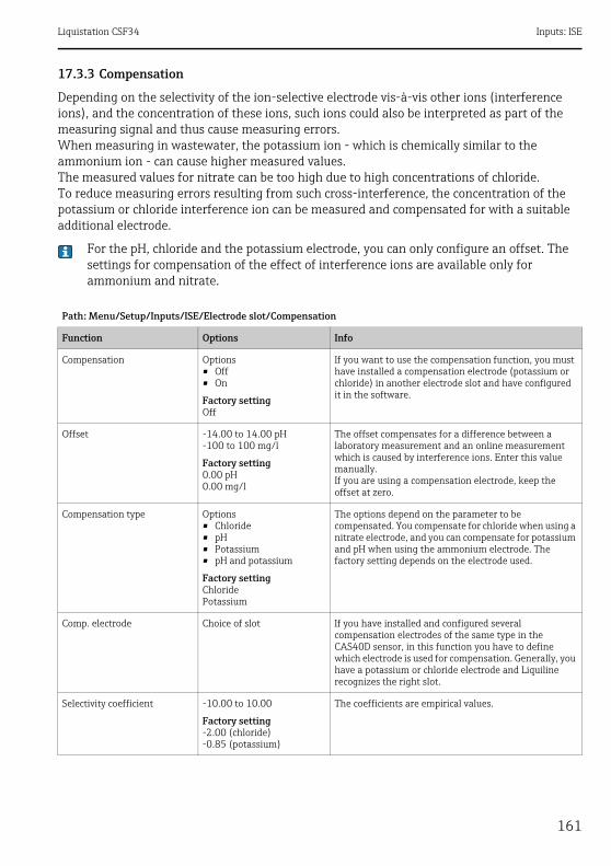
Liquistation CSF34 Inputs: ISE
161
17.3.3 Compensation
Depending on the selectivity of the ion-selective electrode vis-à-vis other ions (interference ions), and the concentration of these ions, such ions could also be interpreted as part of the measuring signal and thus cause measuring errors.When measuring in wastewater, the potassium ion - which is chemically similar to the ammonium ion - can cause higher measured values.The measured values for nitrate can be too high due to high concentrations of chloride.To reduce measuring errors resulting from such cross-interference, the concentration of the potassium or chloride interference ion can be measured and compensated for with a suitable additional electrode.
For the pH, chloride and the potassium electrode, you can only configure an offset. The settings for compensation of the effect of interference ions are available only for ammonium and nitrate.
Path: Menu/Setup/Inputs/ISE/Electrode slot/Compensation
Function Options Info
Compensation Options• Off• On
Factory settingOff
If you want to use the compensation function, you must have installed a compensation electrode (potassium or chloride) in another electrode slot and have configured it in the software.
Offset -14.00 to 14.00 pH-100 to 100 mg/l
Factory setting0.00 pH0.00 mg/l
The offset compensates for a difference between a laboratory measurement and an online measurement which is caused by interference ions. Enter this value manually.If you are using a compensation electrode, keep the offset at zero.
Compensation type Options• Chloride• pH• Potassium• pH and potassium
Factory settingChloridePotassium
The options depend on the parameter to be compensated. You compensate for chloride when using a nitrate electrode, and you can compensate for potassium and pH when using the ammonium electrode. The factory setting depends on the electrode used.
Comp. electrode Choice of slot If you have installed and configured several compensation electrodes of the same type in the CAS40D sensor, in this function you have to define which electrode is used for compensation. Generally, you have a potassium or chloride electrode and Liquiline recognizes the right slot.
Selectivity coefficient -10.00 to 10.00
Factory setting-2.00 (chloride)-0.85 (potassium)
The coefficients are empirical values.
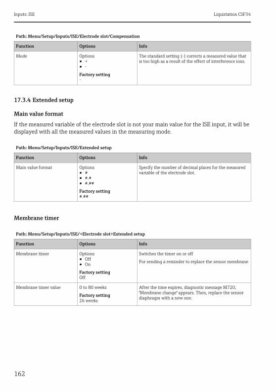
Inputs: ISE Liquistation CSF34
162
17.3.4 Extended setup
Main value format
If the measured variable of the electrode slot is not your main value for the ISE input, it will be displayed with all the measured values in the measuring mode.
Membrane timer
Mode Options• +• -
Factory setting-
The standard setting (-) corrects a measured value that is too high as a result of the effect of interference ions.
Path: Menu/Setup/Inputs/ISE/Extended setup
Function Options Info
Main value format Options• #• #.#• #.##
Factory setting#.##
Specify the number of decimal places for the measured variable of the electrode slot.
Path: Menu/Setup/Inputs/ISE/<Electrode slot>Extended setup
Function Options Info
Membrane timer Options• Off• On
Factory settingOff
Switches the timer on or off
For sending a reminder to replace the sensor membrane
Membrane timer value 0 to 80 weeks
Factory setting26 weeks
After the time expires, diagnostic message M720, "Membrane change" appears. Then, replace the sensor diaphragm with a new one.
Path: Menu/Setup/Inputs/ISE/Electrode slot/Compensation
Function Options Info

Liquistation CSF34 Inputs: ISE
163
Calibration settings
Stability criteria
Buffer recognition (only pH)
Path: Menu/Setup/Inputs/ISE/<Electrode slot>Extended setup/Calib. settings
Function Options Info
Stability criteria Options• Off• Weak• Medium• Hard
Factory settingMedium
In normal situations leave the stability criteria set to "Medium".
Path: Menu/Setup/Inputs/ISE/<Electrode slot>Extended setup/Calib. settings
Function Options Info
Buffer recognition Options• Fixed• Manual
Factory settingFixed
FixedYou choose values from a list. This list depends on the setting for "Buffer manufacturer".
ManualYou enter any two buffer values. These must differ in terms of their pH value.
Buffer manufacturer Options• Endress+Hauser• Ingold/Mettler• DIN 19266• DIN 19267• Merck/Riedel• Hamilton• Special buffer
Factory settingEndress+Hauser
Temperature tables are stored internally in the unit for the following pH values:• Endress+Hauser
2.00 / 4.00 / 7.00 / (9.00) / 9.20 / 10.00 / 12.00• Ingold/Mettler
2.00 / 4.01 / 7.00 / 9.21• DIN 19266
1.68 / 4.01 / 6.86 / 9.18• DIN 19267
1.09 / 4.65 / 6.79 / 9.23 / 12.75• Merck/Riedel
2.00 / 4.01 / 6.98 / 8.95 / 12.00• Hamilton
1.09 / 1.68 / 2.00 / 3.06 / 4.01 / 5.00 / 6.007.00 / 8.00 / 9.21 / 10.01 / 11.00 / 12.00
You have the possibility of defining two buffers of your own with the "Special buffer" option. For this purpose, two tables are displayed in which you can enter value pH value/temperature value pairs.
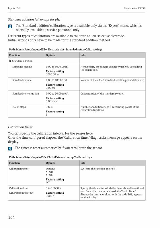
Inputs: ISE Liquistation CSF34
164
Standard addition (all except for pH)
The "Standard addition" calibration type is available only via the "Expert" menu, which is normally available to service personnel only.
Different types of calibration are available to calibrate an ion-selective electrode.Initial settings only have to be made for the standard addition method.
Calibration timer
You can specify the calibration interval for the sensor here.Once the time configured elapses, the "Calibration timer" diagnostics message appears on the display.
The timer is reset automatically if you recalibrate the sensor.
Path: Menu/Setup/Inputs/ISE/<Electrode slot>Extended setup/Calib. settings
Function Options Info
Standard addition
Sampling volume 0.00 to 5000.00 ml
Factory setting1000.00 ml
Here, specify the sample volume which you use during the calibration.
Standard volume 0.00 to 100.00 ml
Factory setting1.00 ml
Volume of the added standard solution per addition step
Standard concentration 0.00 to 10.00 mol/l
Factory setting1.00 mol/l
Concentration of the standard solution
No. of steps 1 to 4
Factory setting3
Number of addition steps (=measuring points of the calibration function)
Path: Menu/Setup/Inputs/ISE/<Slot>/Extended setup/Calib. settings
Function Options Info
Calibration timer Options• Off• On
Factory settingOff
Switches the function on or off
Calibration timer
Calibration timer="On"
1 to 10000 h
Factory setting1000 h
Specify the time after which the timer should have timed out. Once this time has elapsed, the "Calib. Timer" diagnostics message, along with the code 102, appears on the display.
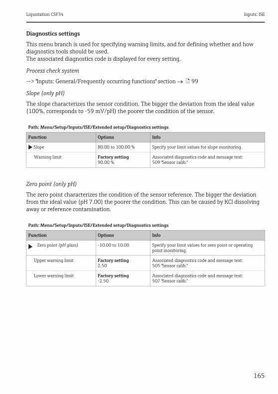
Liquistation CSF34 Inputs: ISE
165
Diagnostics settings
This menu branch is used for specifying warning limits, and for defining whether and how diagnostics tools should be used.The associated diagnostics code is displayed for every setting.
Process check system
--> "Inputs: General/Frequently occurring functions" section ä 99
Slope (only pH)
The slope characterizes the sensor condition. The bigger the deviation from the ideal value (100%, corresponds to -59 mV/pH) the poorer the condition of the sensor.
Zero point (only pH)
The zero point characterizes the condition of the sensor reference. The bigger the deviation from the ideal value (pH 7.00) the poorer the condition. This can be caused by KCl dissolving away or reference contamination.
Path: Menu/Setup/Inputs/ISE/Extended setup/Diagnostics settings
Function Options Info
Slope 80.00 to 100.00 % Specify your limit values for slope monitoring.
Warning limit Factory setting90.00 %
Associated diagnostics code and message text:509 "Sensor calib."
Path: Menu/Setup/Inputs/ISE/Extended setup/Diagnostics settings
Function Options Info
Zero point (pH glass) -10.00 to 10.00 Specify your limit values for zero point or operating point monitoring.
Upper warning limit Factory setting2.50
Associated diagnostics code and message text:505 "Sensor calib."
Lower warning limit Factory setting-2.50
Associated diagnostics code and message text:507 "Sensor calib."
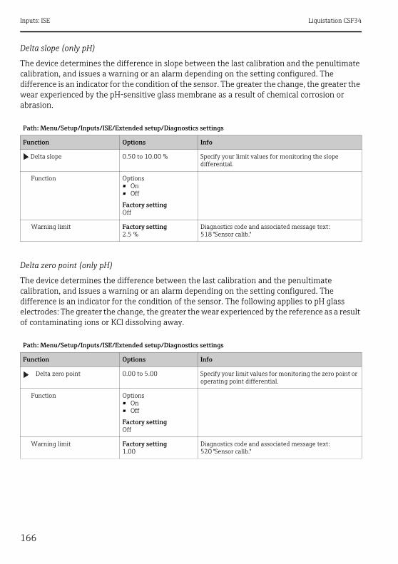
Inputs: ISE Liquistation CSF34
166
Delta slope (only pH)
The device determines the difference in slope between the last calibration and the penultimate calibration, and issues a warning or an alarm depending on the setting configured. The difference is an indicator for the condition of the sensor. The greater the change, the greater the wear experienced by the pH-sensitive glass membrane as a result of chemical corrosion or abrasion.
Delta zero point (only pH)
The device determines the difference between the last calibration and the penultimate calibration, and issues a warning or an alarm depending on the setting configured. The difference is an indicator for the condition of the sensor. The following applies to pH glass electrodes: The greater the change, the greater the wear experienced by the reference as a result of contaminating ions or KCl dissolving away.
Path: Menu/Setup/Inputs/ISE/Extended setup/Diagnostics settings
Function Options Info
Delta slope 0.50 to 10.00 % Specify your limit values for monitoring the slope differential.
Function Options• On• Off
Factory settingOff
Warning limit Factory setting2.5 %
Diagnostics code and associated message text:518 "Sensor calib."
Path: Menu/Setup/Inputs/ISE/Extended setup/Diagnostics settings
Function Options Info
Delta zero point 0.00 to 5.00 Specify your limit values for monitoring the zero point or operating point differential.
Function Options• On• Off
Factory settingOff
Warning limit Factory setting1.00
Diagnostics code and associated message text:520 "Sensor calib."

Liquistation CSF34 Inputs: ISE
167
17.4 Limits operating hoursThe total operating time of the sensor and its use under extreme conditions is monitored. If the operating time exceeds the defined threshold values, the device issues a corresponding diagnostics message.
Each sensor has a limited life expectancy which heavily depends on the operating conditions. If you specify warning limits for operating times under extreme conditions, you can guarantee the operation of your measuring point without any downtime by performing maintenance tasks in time.
Path: Menu/Setup/Inputs/ISE
Function Options Info
Limits operating hours Specify your limit values for monitoring the number of operating hours under extreme conditions.
The range of adjustment for the operating hours alarm and warning limits is generally 1 to 50000 h.
Function Options• On• Off
Factory settingOff
OnThe operation of the sensor under extreme conditions is monitored, recorded in the sensor and diagnostics messages are displayed on the controller.OffNo diagnostics messages. However, the time the sensor operates under extreme conditions is recorded in the sensor and can be read in the sensor information in the diagnostics menu.
Operating time Total operating time of the sensor
Warning limit Factory setting36000 h
Diagnostics code and associated message text:199 "Operating time"
Operation > 30°C
Warning limit Factory setting36000 h
Diagnostics code and associated message text:191 "Operating time"
Operation > 40°C
Warning limit Factory setting36000 h
Diagnostics code and associated message text:192 "Operating time"

Inputs: Interface Liquistation CSF34
168
18 Inputs: Interface
18.1 Basic settingsThe CUS71DOUS71D is not detected automatically. It must be selected manually (Current sensor). During initial commissioning, data are recorded and calculated for 3 to 5 minutes before a measured value is displayed.
18.2 Manual hold--> "Inputs: General/Frequently occurring functions" section ä 99
Path: Menu/Setup/Inputs/Ultrasonic interface
Function Options Info
Sensor operation Options• Scan for memosens
sensor• Current sensor
Factory settingCurrent sensor
Scan for memosens sensorSearches for Memosens sensors
Current sensorConnected sensor is used
Wiper function Options• Off• On
Factory settingOn
Only for sensor version with wiper function
Wiper timing 1 to 240 min
Factory setting10 min
Only for sensor version with wiper function
Turbidity measurement Options• Off• On
Factory settingOn
Only for sensor version with integrated turbidity measurement and wiper function
Turbidity unit Options• FNU• NTU
Factory settingFNU
Only for sensor version with integrated turbidity measurement and wiper function
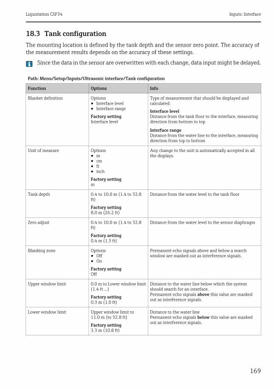
Liquistation CSF34 Inputs: Interface
169
18.3 Tank configurationThe mounting location is defined by the tank depth and the sensor zero point. The accuracy of the measurement results depends on the accuracy of these settings.
Since the data in the sensor are overwritten with each change, data input might be delayed.
Path: Menu/Setup/Inputs/Ultrasonic interface/Tank configuration
Function Options Info
Blanket definition Options• Interface level• Interface range
Factory settingInterface level
Type of measurement that should be displayed and calculated:
Interface levelDistance from the tank floor to the interface, measuring direction from bottom to top
Interface rangeDistance from the water line to the interface, measuring direction from top to bottom
Unit of measure Options• m• cm• ft• inch
Factory settingm
Any change to the unit is automatically accepted in all the displays.
Tank depth 0.4 to 10.0 m (1.4 to 32.8 ft)
Factory setting8.0 m (26.2 ft)
Distance from the water level to the tank floor
Zero adjust 0.4 to 10.0 m (1.4 to 32.8 ft)
Factory setting0.4 m (1.3 ft)
Distance from the water level to the sensor diaphragm
Blanking zone Options• Off• On
Factory settingOff
Permanent echo signals above and below a search window are masked out as interference signals.
Upper window limit 0.0 m to Lower window limit(1.4 ft ...)
Factory setting0.3 m (1.0 ft)
Distance to the water line below which the system should search for an interface.Permanent echo signals above this value are masked out as interference signals.
Lower window limit Upper window limit to 11.0 m (to 32.8 ft)
Factory setting3.3 m (10.8 ft)
Distance to the water linePermanent echo signals below this value are masked out as interference signals.
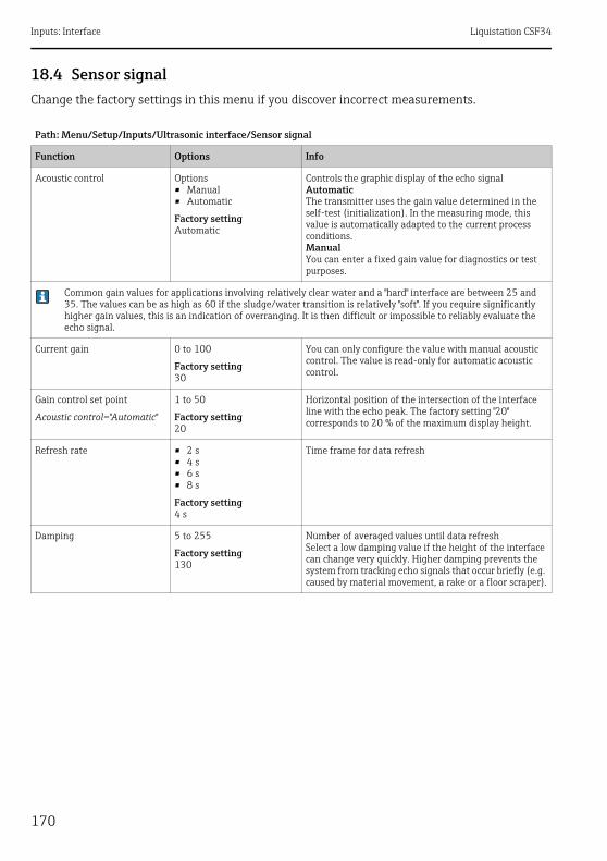
Inputs: Interface Liquistation CSF34
170
18.4 Sensor signalChange the factory settings in this menu if you discover incorrect measurements.
Path: Menu/Setup/Inputs/Ultrasonic interface/Sensor signal
Function Options Info
Acoustic control Options• Manual• Automatic
Factory settingAutomatic
Controls the graphic display of the echo signalAutomaticThe transmitter uses the gain value determined in the self-test (initialization). In the measuring mode, this value is automatically adapted to the current process conditions.ManualYou can enter a fixed gain value for diagnostics or test purposes.
Common gain values for applications involving relatively clear water and a "hard" interface are between 25 and 35. The values can be as high as 60 if the sludge/water transition is relatively "soft". If you require significantly higher gain values, this is an indication of overranging. It is then difficult or impossible to reliably evaluate the echo signal.
Current gain 0 to 100
Factory setting30
You can only configure the value with manual acoustic control. The value is read-only for automatic acoustic control.
Gain control set point
Acoustic control="Automatic"
1 to 50
Factory setting20
Horizontal position of the intersection of the interface line with the echo peak. The factory setting "20" corresponds to 20 % of the maximum display height.
Refresh rate • 2 s• 4 s• 6 s• 8 s
Factory setting4 s
Time frame for data refresh
Damping 5 to 255
Factory setting130
Number of averaged values until data refreshSelect a low damping value if the height of the interface can change very quickly. Higher damping prevents the system from tracking echo signals that occur briefly (e.g. caused by material movement, a rake or a floor scraper).
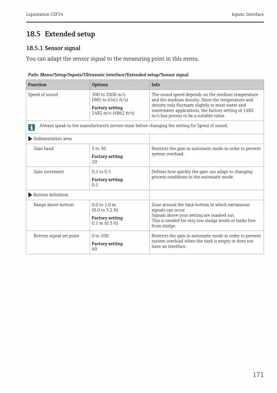
Liquistation CSF34 Inputs: Interface
171
18.5 Extended setup
18.5.1 Sensor signal
You can adapt the sensor signal to the measuring point in this menu.
Path: Menu/Setup/Inputs/Ultrasonic interface/Extended setup/Sensor signal
Function Options Info
Speed of sound 300 to 2000 m/s(985 to 6561 ft/s)
Factory setting1482 m/s (4862 ft/s)
The sound speed depends on the medium temperature and the medium density. Since the temperature and density only fluctuate slightly in most water and wastewater applications, the factory setting of 1482 m/s has proven to be a suitable value.
Always speak to the manufacturer's service team before changing the setting for Speed of sound.
Sedimentation area
Gain band 5 to 30
Factory setting20
Restricts the gain in automatic mode in order to prevent system overload.
Gain increment 0.1 to 0.5
Factory setting0.1
Defines how quickly the gain can adapt to changing process conditions in the automatic mode.
Bottom definition
Range above bottom 0.0 to 1.0 m(0.0 to 3.2 ft)
Factory setting0.1 m (0.3 ft)
Zone around the tank bottom in which extraneous signals can occur.Signals above your setting are masked out.This is needed for very low sludge levels or tanks free from sludge.
Bottom signal set point 0 to 100
Factory setting60
Restricts the gain in automatic mode in order to prevent system overload when the tank is empty or does not have an interface.

Inputs: Interface Liquistation CSF34
172
18.5.2 Calculation
18.5.3 Diagnostics settings
This menu branch is used for specifying warning limits, and for defining whether and how diagnostics tools should be used.The associated diagnostics code is displayed for every setting.
Alarm delay echo loss
Path: Menu/Setup/Inputs/Ultrasonic interface/Extended setup/Calculation
Function Options Info
Interface Options• Top layer• Lower interface
Factory settingTop layer
Defines which signal the system should track and display when several interfaces are calculated.
Top layerDetermine the interface of thin material in the upper section
Lower interfaceDetermine the interface of thicker material near the floor
Interface window Options• Off• On
Factory settingOff
You can open another window near the interface. Specify a distance above and below the interface. The system primarily focuses on the signal within this window.Any signal outside this window must meet the search criteria for an interface for an extended period before the system recognizes it as an interface.
Above interface
Interface window="On"
0.0 to 10.0 m(0.0 to 32.8 ft)
Factory setting0.6 m (2.0 ft)
The search window is indicated by broken lines in the graphic mode.The search window is 1.2 m wide in the factory setting for both parameters.Below interface
Interface window="On"
Gate response rate 0 to 50
Factory setting1
The response rate determines the speed at which the system updates the measuring window.A high value stands for a quick change.
Threshold 0 to 100
Factory setting0
Filter for examining signalsIf a high value is selected, stronger signals are taken into account more. If a low value is selected, weaker signals are taken into account more.
Path: Menu/Setup/Inputs/Ultrasonic interface/Extended setup/Diagnostics settings
Function Options Info
Alarm delay echo loss 0 to 255 min
Factory setting10 min
Delay time for an error message if the echo is lost
Liquistation CSF34 Inputs: Interface
173
Diagnostic behavior
--> "Inputs: General/Frequently occurring functions" section ä 99
18.5.4 Restart the sensor signal
The sensor is reinitialized with the "Restart sensor signal" action.The sensor starts in the automatic mode and searches for the interface with the last sensor settings. The first measured value appears after around 3 to 5 minutes.
18.5.5 Sensor replacement
--> "Inputs: General/Frequently occurring functions" section ä 99
18.5.6 Data processing factory setting
--> "Inputs: General/Frequently occurring functions" section ä 99
18.5.7 Sensor factory setting
--> "Inputs: General/Frequently occurring functions" section ä 99

Liquistation CSF34
174
Index
AActivation code . . . . . . . . . . . . . . . . . . . . . . . . . 22Additional functions
Cleaning programs . . . . . . . . . . . . . . . . . . . . 87Limit switch . . . . . . . . . . . . . . . . . . . . . . . . . 83Mathematical functions . . . . . . . . . . . . . . . . 89
Alarm relayCleaning . . . . . . . . . . . . . . . . . . . . . . . . . . . . 80Diagnostics message. . . . . . . . . . . . . . . . . . . 79Limit switch . . . . . . . . . . . . . . . . . . . . . . . . . 79
Automatic hold . . . . . . . . . . . . . . . . . . . . . . . . . . 8
BBasic program . . . . . . . . . . . . . . . . . . . . . . . . . . 35Basic settings . . . . . . . . . . . . . . . . . . . . . . . . . . . 6
Chlorine . . . . . . . . . . . . . . . . . . . . . . . . . . . 135Conductivity . . . . . . . . . . . . . . . . . . . . . . . . 115Interface measurement . . . . . . . . . . . . . . . 168ISE . . . . . . . . . . . . . . . . . . . . . . . . . . . . . . . . 158Nitrate. . . . . . . . . . . . . . . . . . . . . . . . . . . . . 153Oxygen . . . . . . . . . . . . . . . . . . . . . . . . . . . . 125pH/ORP . . . . . . . . . . . . . . . . . . . . . . . . . . . . 106SAC . . . . . . . . . . . . . . . . . . . . . . . . . . . . . . . 148Turbidity . . . . . . . . . . . . . . . . . . . . . . . . . . . 143
Binary inputs . . . . . . . . . . . . . . . . . . . . . . . . . . 23Binary outputs . . . . . . . . . . . . . . . . . . . . . . . . . 73Bottle synchronization . . . . . . . . . . . . . . . . . . . 34Bus address . . . . . . . . . . . . . . . . . . . . . . . . . . . . 17
CCalibration settings
Chlorine . . . . . . . . . . . . . . . . . . . . . . . . . . . 137ISE . . . . . . . . . . . . . . . . . . . . . . . . . . . . . . . . 163Nitrate. . . . . . . . . . . . . . . . . . . . . . . . . . . . . 155Oxygen . . . . . . . . . . . . . . . . . . . . . . . . . . . . 128pH/ORP . . . . . . . . . . . . . . . . . . . . . . . . . . . . 108SAC . . . . . . . . . . . . . . . . . . . . . . . . . . . . . . . 149Turbidity . . . . . . . . . . . . . . . . . . . . . . . . . . . 144
Calibration timer. . . . . . . . . . . . . . . . . . 100, 164Calibrations
Cap, chlorine . . . . . . . . . . . . . . . . . . . . . . . . 140Calibrations, cap . . . . . . . . . . . . . . . . . . . . . . . 131
CapCalibrations . . . . . . . . . . . . . . . . . . . . . . . . 131Chlorine calibrations . . . . . . . . . . . . . . . . . 140Sterilizations . . . . . . . . . . . . . . . . . . . . . . . 132
Cell constant . . . . . . . . . . . . . . . . . . . . . . . . . 115Chloride compensation . . . . . . . . . . . . . . . . . 161Chlorine
Basic settings. . . . . . . . . . . . . . . . . . . . . . . 135Calibration settings . . . . . . . . . . . . . . . . . . 137Diagnostics settings . . . . . . . . . . . . . . . . . 138Extended setup . . . . . . . . . . . . . . . . . . . . . 136Main value. . . . . . . . . . . . . . . . . . . . . . . . . 135Medium compensation . . . . . . . . . . . . . . . 136Unit . . . . . . . . . . . . . . . . . . . . . . . . . . . . . . 136
Cleaning. . . . . . . . . . . . . . . . . . . . . . . . . . . . . 100Cleaning programs . . . . . . . . . . . . . . . . . . . . . 87Communication
Fieldbus . . . . . . . . . . . . . . . . . . . . . . . . . . . . 97HART . . . . . . . . . . . . . . . . . . . . . . . . . . . . . . 97Modbus . . . . . . . . . . . . . . . . . . . . . . . . . . . . 97PROFIBUS-DP . . . . . . . . . . . . . . . . . . . . . . . 97Service interface . . . . . . . . . . . . . . . . . . . . . 96Web server . . . . . . . . . . . . . . . . . . . . . . . . . 94
ConductivityDiagnostics settings . . . . . . . . . . . . . . . . . 121Extended setup . . . . . . . . . . . . . . . . . . . . . 121Format . . . . . . . . . . . . . . . . . . . . . . . . . . . . 118Temperature format . . . . . . . . . . . . . . . . . 121Unit . . . . . . . . . . . . . . . . . . . . . . . . . . . . . . 118
ConnectionService interface . . . . . . . . . . . . . . . . . . . . . 96Web server . . . . . . . . . . . . . . . . . . . . . . . . . 94
Creating a connectionWeb server . . . . . . . . . . . . . . . . . . . . . . . . . 94
Current inputs . . . . . . . . . . . . . . . . . . . . . . . . . 27

Liquistation CSF34
DDamping . . . . . . . . . . . . . . . . . . . . . . . . . 99, 158Data administration
Firmware update . . . . . . . . . . . . . . . . . . . . . 20Loading the setup. . . . . . . . . . . . . . . . . . . . . 21Saving the setup . . . . . . . . . . . . . . . . . . . . . . 20
Data managementActivation code. . . . . . . . . . . . . . . . . . . . . . . 22Exporting the setup . . . . . . . . . . . . . . . . . . . 21
Data processing . . . . . . . . . . . . . . . . . . . . . . . 105Date and time . . . . . . . . . . . . . . . . . . . . . . . . . . . 7Delta slope
Chlorine . . . . . . . . . . . . . . . . . . . . . . . . . . . 139ISE. . . . . . . . . . . . . . . . . . . . . . . . . . . . . . . . 166Oxygen . . . . . . . . . . . . . . . . . . . . . . . . . . . . 130pH . . . . . . . . . . . . . . . . . . . . . . . . . . . . . . . . 113
Delta zero pointChlorine . . . . . . . . . . . . . . . . . . . . . . . . . . . 140ISE. . . . . . . . . . . . . . . . . . . . . . . . . . . . . . . . 166Oxygen . . . . . . . . . . . . . . . . . . . . . . . . . . . . 131pH . . . . . . . . . . . . . . . . . . . . . . . . . . . . . . . . 114
Device variables . . . . . . . . . . . . . . . . . . . . . . . . 81PROFIBUS . . . . . . . . . . . . . . . . . . . . . . . . . . . 81
Diagnostics settings . . . . . . . . . . . . . . . . . . . . . 16Chlorine . . . . . . . . . . . . . . . . . . . . . . . . . . . 138Chlorine slope. . . . . . . . . . . . . . . . . . . . . . . 138Conductivity . . . . . . . . . . . . . . . . . . . . . . . . 121Delta slope chlorine . . . . . . . . . . . . . . . . . . 139Delta slope ISE . . . . . . . . . . . . . . . . . . . . . . 166Delta slope oxygen . . . . . . . . . . . . . . . . . . . 130Delta slope pH . . . . . . . . . . . . . . . . . . . . . . 113Delta zero point chlorine . . . . . . . . . . . . . . 140Delta zero point ISE . . . . . . . . . . . . . . . . . . 166Delta zero point oxygen . . . . . . . . . . . . . . . 131Delta zero point pH . . . . . . . . . . . . . . . . . . 114Diagnostic behavior . . . . . . . . . . . . . . . . . . 102Interface . . . . . . . . . . . . . . . . . . . . . . . . . . . 172ISE. . . . . . . . . . . . . . . . . . . . . . . . . . . . . . . . 165Nitrate . . . . . . . . . . . . . . . . . . . . . . . . . . . . 155Operating hours conductivity. . . . . . . . . . . 122Operating hours ISE . . . . . . . . . . . . . . . . . . 167Operating hours oxygen. . . . . . . . . . . . . . . 132Operating hours pH/ORP . . . . . . . . . . . . . . 112Operating hours, chlorine . . . . . . . . . . . . . 141Operating hours, nitrate . . . . . . . . . . . . . . 155Operating hours, SAC. . . . . . . . . . . . . . . . . 150Operating hours, turbidity . . . . . . . . . . . . . 145Oxygen . . . . . . . . . . . . . . . . . . . . . . . . . . . . 129
pH/ORP . . . . . . . . . . . . . . . . . . . . . . . . . . . 109Polarization detection . . . . . . . . . . . . . . . . 123Process check system . . . . . . . . . . . . . . . . 121SAC . . . . . . . . . . . . . . . . . . . . . . . . . . . . . . 150Sensor check system . . . . . . . . . . . . . . . . . 109Sensor condition check . . . . . . . . . . . 111–112Slope ISE . . . . . . . . . . . . . . . . . . . . . . . . . . 165Slope oxygen . . . . . . . . . . . . . . . . . . . . . . . 129Slope pH . . . . . . . . . . . . . . . . . . . . . . . . . . 110Turbidity . . . . . . . . . . . . . . . . . . . . . . . . . . 145Zero point chlorine . . . . . . . . . . . . . . . . . . 139Zero point ISE . . . . . . . . . . . . . . . . . . . . . . 165Zero point Oxygen. . . . . . . . . . . . . . . . . . . 130Zero point pH . . . . . . . . . . . . . . . . . . . . . . 111
EElectrode slot. . . . . . . . . . . . . . . . . . . . . . . . . 160Electrolyte counter . . . . . . . . . . . . . . . . . . . . 142EP . . . . . . . . . . . . . . . . . . . . . . . . . . . . . . . . . 124Extended setup
Chlorine. . . . . . . . . . . . . . . . . . . . . . . . . . . 136Conductivity . . . . . . . . . . . . . . . . . . . . . . . 121Data management . . . . . . . . . . . . . . . . . . . 20Diagnostics settings . . . . . . . . . . . . . . . . . . 16HART bus address . . . . . . . . . . . . . . . . . . . . 17Interface . . . . . . . . . . . . . . . . . . . . . . . . . . 171ISE . . . . . . . . . . . . . . . . . . . . . . . . . . . 159, 162Nitrate . . . . . . . . . . . . . . . . . . . . . . . . . . . . 154Oxygen . . . . . . . . . . . . . . . . . . . . . . . . . . . 126pH/ORP . . . . . . . . . . . . . . . . . . . . . . . . . . . 107SAC . . . . . . . . . . . . . . . . . . . . . . . . . . . . . . 149Turbidity . . . . . . . . . . . . . . . . . . . . . . . . . . 144
FFactory setting
Data processing. . . . . . . . . . . . . . . . . . . . . 105Sensor . . . . . . . . . . . . . . . . . . . . . . . . . . . . 105
Fieldbus . . . . . . . . . . . . . . . . . . . . . . . . . . . . . . 97Firmware update
Controller . . . . . . . . . . . . . . . . . . . . . . . . . . 20Flow-paced program . . . . . . . . . . . . . . . . . . . . 41

Liquistation CSF34
176
GGeneral settings
Automatic hold . . . . . . . . . . . . . . . . . . . . . . . . 8Basic settings . . . . . . . . . . . . . . . . . . . . . . . . . 6Date and time . . . . . . . . . . . . . . . . . . . . . . . . . 7Extended setup . . . . . . . . . . . . . . . . . . . . . . . 16Logbooks. . . . . . . . . . . . . . . . . . . . . . . . . . . . . 9
HHART. . . . . . . . . . . . . . . . . . . . . . . . . . . . . 81, 97
IInputs
Chlorine . . . . . . . . . . . . . . . . . . . . . . . . . . . 135Conductivity . . . . . . . . . . . . . . . . . . . . . . . . 115General . . . . . . . . . . . . . . . . . . . . . . . . . . . . . 99Interface . . . . . . . . . . . . . . . . . . . . . . . . . . . 168ISE . . . . . . . . . . . . . . . . . . . . . . . . . . . . . . . . 158Nitrate. . . . . . . . . . . . . . . . . . . . . . . . . . . . . 153Oxygen . . . . . . . . . . . . . . . . . . . . . . . . . . . . 125pH/ORP . . . . . . . . . . . . . . . . . . . . . . . . . . . . 106SAC . . . . . . . . . . . . . . . . . . . . . . . . . . . . . . . 148Turbidity and solids . . . . . . . . . . . . . . . . . . 143
Installation factor . . . . . . . . . . . . . . . . . . . . . . 116Interface
Alarm delay . . . . . . . . . . . . . . . . . . . . . . . . 172Calculation . . . . . . . . . . . . . . . . . . . . . . . . . 172Diagnostics settings . . . . . . . . . . . . . . . . . . 172Extended setup . . . . . . . . . . . . . . . . . . . . . . 171Sensor signal. . . . . . . . . . . . . . . . . . . 170–171Signal restart . . . . . . . . . . . . . . . . . . . . . . . 173Tank configuration . . . . . . . . . . . . . . . . . . . 169
Interface measurementBasic settings . . . . . . . . . . . . . . . . . . . . . . . 168
ISEBasic settings . . . . . . . . . . . . . . . . . . . . . . . 158Calibration settings . . . . . . . . . . . . . . . . . . 163Compensation K and Cl . . . . . . . . . . . . . . . 161Diagnostics settings . . . . . . . . . . . . . . . . . . 165Electrode slot . . . . . . . . . . . . . . . . . . . . . . . 160Extended setup . . . . . . . . . . . . . . . . . 159, 162Main value . . . . . . . . . . . . . . . . . . . . . . . . . 158Membrane timer . . . . . . . . . . . . . . . . . . . . 162Standard addition . . . . . . . . . . . . . . . . . . . . 164
LLimit switch . . . . . . . . . . . . . . . . . . . . . . . 79, 83Logbooks. . . . . . . . . . . . . . . . . . . . . . . . . . . . . . . 9
MMain value
Chlorine . . . . . . . . . . . . . . . . . . . . . . . . . . . 135ISE . . . . . . . . . . . . . . . . . . . . . . . . . . . . . . . 158Oxygen. . . . . . . . . . . . . . . . . . . . . . . . . . . . 125
Manual hold . . . . . . . . . . . . . . . . . . . . . . . . . 100Mathematical functions
Degassed conductivity . . . . . . . . . . . . . . . . . 91Difference . . . . . . . . . . . . . . . . . . . . . . . . . . 89Dual conductivity . . . . . . . . . . . . . . . . . . . . . 92pH calculation . . . . . . . . . . . . . . . . . . . . . . . 93Redundancy . . . . . . . . . . . . . . . . . . . . . . . . . 90rH value . . . . . . . . . . . . . . . . . . . . . . . . . . . . 90
Measured value formatsNitrate . . . . . . . . . . . . . . . . . . . . . . . . . . . . 154SAC . . . . . . . . . . . . . . . . . . . . . . . . . . . . . . 149Turbidity . . . . . . . . . . . . . . . . . . . . . . . . . . 144
Medium compensationChlorine . . . . . . . . . . . . . . . . . . . . . . . . . . . 136Oxygen. . . . . . . . . . . . . . . . . . . . . . . . 127, 129pH . . . . . . . . . . . . . . . . . . . . . . . . . . . . . . . 107
Membrane timer . . . . . . . . . . . . . . . . . . . . . . 162Modbus . . . . . . . . . . . . . . . . . . . . . . . . . . . . . . 97Modbus RS485 . . . . . . . . . . . . . . . . . . . . . . . . 82Modbus TCP . . . . . . . . . . . . . . . . . . . . . . . . . . 82
NNitrate
Basic settings. . . . . . . . . . . . . . . . . . . . . . . 153Calibration settings . . . . . . . . . . . . . . . . . . 155Diagnostics settings . . . . . . . . . . . . . . . . . 155Extended setup . . . . . . . . . . . . . . . . . . . . . 154Formats . . . . . . . . . . . . . . . . . . . . . . . . . . . 154Stability criteria . . . . . . . . . . . . . . . . . . . . . 155

Liquistation CSF34
OOperating hours
Chlorine . . . . . . . . . . . . . . . . . . . . . . . . . . . 141Conductivity . . . . . . . . . . . . . . . . . . . . . . . . 122ISE. . . . . . . . . . . . . . . . . . . . . . . . . . . . . . . . 167Nitrate . . . . . . . . . . . . . . . . . . . . . . . . . . . . 155Oxygen . . . . . . . . . . . . . . . . . . . . . . . . . . . . 132pH/ORP . . . . . . . . . . . . . . . . . . . . . . . . . . . 112SAC . . . . . . . . . . . . . . . . . . . . . . . . . . . . . . . 150Turbidity . . . . . . . . . . . . . . . . . . . . . . . . . . . 145
Operating mode . . . . . . . . . . . . . . . . . . . . . . . 115Operation
Via service interface . . . . . . . . . . . . . . . . . . . 97Via web server . . . . . . . . . . . . . . . . . . . . . . . 95
OutputsAlarm relays . . . . . . . . . . . . . . . . . . . . . . . . . 78Binary outputs . . . . . . . . . . . . . . . . . . . . . . . 73Current outputs . . . . . . . . . . . . . . . . . . . . . . 76
OxygenBasic settings . . . . . . . . . . . . . . . . . . . . . . . 125Calibration settings . . . . . . . . . . . . . . . . . . 128Diagnostics settings . . . . . . . . . . . . . . . . . . 129Extended setup. . . . . . . . . . . . . . . . . . . . . . 126Main value . . . . . . . . . . . . . . . . . . . . . . . . . 125Temperature compensation . . . . . . . . . . . . 126Unit. . . . . . . . . . . . . . . . . . . . . . . . . . . . . . . 126
PpH/ORP
Basic settings . . . . . . . . . . . . . . . . . . . . . . . 106Calibration settings . . . . . . . . . . . . . . . . . . 108diagnostics settings . . . . . . . . . . . . . . . . . . 109Extended setup. . . . . . . . . . . . . . . . . . . . . . 107Tag control . . . . . . . . . . . . . . . . . . . . . . . . . 104
Pharmaceutical water . . . . . . . . . . . . . . . . . . 124Polarization detection . . . . . . . . . . . . . . . . . . 123Potassium compensation . . . . . . . . . . . . . . . . 161Process check system . . . . . . . . . . . . . . 101, 121PROFIBUS
Device variables . . . . . . . . . . . . . . . . . . . . . . 81PROFIBUS variables . . . . . . . . . . . . . . . . . . . 81
PROFIBUS DP . . . . . . . . . . . . . . . . . . . . . . . . . . 81PROFIBUS-DP . . . . . . . . . . . . . . . . . . . . . . . . . . 97
Program typeAdvanced . . . . . . . . . . . . . . . . . . . . . . . . . . 60Basic . . . . . . . . . . . . . . . . . . . . . . . . . . . . . . 35external signal . . . . . . . . . . . . . . . . . . . . . . 51Flow-paced . . . . . . . . . . . . . . . . . . . . . . . . . 41Standard . . . . . . . . . . . . . . . . . . . . . . . . . . . 55Time/flow-paced. . . . . . . . . . . . . . . . . . . . . 46Time-paced . . . . . . . . . . . . . . . . . . . . . . . . . 37
Program types . . . . . . . . . . . . . . . . . . . . . . . . . 31
RRelay
Cleaning . . . . . . . . . . . . . . . . . . . . . . . . . . . 80Diagnostics message . . . . . . . . . . . . . . . . . . 79Limit switch. . . . . . . . . . . . . . . . . . . . . . . . . 79
SSAC
Basic settings . . . . . . . . . . . . . . . . . . . . . . 148Calibration settings . . . . . . . . . . . . . . . . . . 149Diagnostics settings . . . . . . . . . . . . . . . . . 150Extended setup . . . . . . . . . . . . . . . . . . . . . 149Formats . . . . . . . . . . . . . . . . . . . . . . . . . . . 149Stability criteria. . . . . . . . . . . . . . . . . . . . . 150
Sampling methods . . . . . . . . . . . . . . . . . . . . . 31Sensor check system . . . . . . . . . . . . . . . . . . . 109Sensor condition check . . . . . . . . . . . . . 111–112Sensor factory setting . . . . . . . . . . . . . . . . . . 105Sensor identification . . 106, 115, 125, 135, 143, 148, 153, 158Sensor replacement. . . . . . . . . . . . . . . . . . . . 105Sensor signal . . . . . . . . . . . . . . . . . . . . . 170–171Service interface
Connection . . . . . . . . . . . . . . . . . . . . . . . . . 96Setup
Export . . . . . . . . . . . . . . . . . . . . . . . . . . . . . 21Load. . . . . . . . . . . . . . . . . . . . . . . . . . . . . . . 21Save . . . . . . . . . . . . . . . . . . . . . . . . . . . . . . . 20
SlopeChlorine. . . . . . . . . . . . . . . . . . . . . . . . . . . 138ISE . . . . . . . . . . . . . . . . . . . . . . . . . . . . . . . 165Oxygen . . . . . . . . . . . . . . . . . . . . . . . . . . . 129pH . . . . . . . . . . . . . . . . . . . . . . . . . . . . . . . 110

Liquistation CSF34
178
Stability criteriaChlorine . . . . . . . . . . . . . . . . . . . . . . 137, 163Nitrate. . . . . . . . . . . . . . . . . . . . . . . . . . . . . 155Oxygen . . . . . . . . . . . . . . . . . . . . . . . . . . . . 128pH/ORP . . . . . . . . . . . . . . . . . . . . . . . . . . . . 108SAC . . . . . . . . . . . . . . . . . . . . . . . . . . . . . . . 150Turbidity . . . . . . . . . . . . . . . . . . . . . . . . . . . 145
Standard addition . . . . . . . . . . . . . . . . . . . . . . 164Sterilizations . . . . . . . . . . . . . . . . . . . . . . . . . . 104Sterilizations, cap . . . . . . . . . . . . . . . . . . . . . . 132
TTag control . . . . . . . . . . . . . . . . . . . . . . . . . . . 104Tank configuration . . . . . . . . . . . . . . . . . . . . . 169Temperature compensation . . . . . . . . . . . . . . 118
Oxygen . . . . . . . . . . . . . . . . . . . . . . . . . . . . 126Temperature format . . . . . . . . . . . . . . . . . . . . 121Time/flow-paced program . . . . . . . . . . . . . . . . 46Time-paced program . . . . . . . . . . . . . . . . . . . . 37Turbidity
Basic settings . . . . . . . . . . . . . . . . . . . . . . . 143Calibration settings . . . . . . . . . . . . . . . . . . 144Diagnostics settings . . . . . . . . . . . . . . . . . . 145Extended setup . . . . . . . . . . . . . . . . . . . . . . 144Formats. . . . . . . . . . . . . . . . . . . . . . . . . . . . 144Stability criteria . . . . . . . . . . . . . . . . . . . . . 145
UUnit
Chlorine . . . . . . . . . . . . . . . . . . . . . . . . . . . 136Oxygen . . . . . . . . . . . . . . . . . . . . . . . . . . . . 126
USP . . . . . . . . . . . . . . . . . . . . . . . . . . . . . . . . . 124
WWeb server
Connection . . . . . . . . . . . . . . . . . . . . . . . . . . 94Creating a connection. . . . . . . . . . . . . . . . . . 94Operation . . . . . . . . . . . . . . . . . . . . . . . . . . . 95
ZZero point
Chlorine . . . . . . . . . . . . . . . . . . . . . . . . . . . 139ISE . . . . . . . . . . . . . . . . . . . . . . . . . . . . . . . . 165Oxygen . . . . . . . . . . . . . . . . . . . . . . . . . . . . 130pH . . . . . . . . . . . . . . . . . . . . . . . . . . . . . . . . 111

Liquistation CSF34

www.addresses.endress.com