operating instructions - nag marine - home · 2017-12-29 · operating instructions. pressure...
TRANSCRIPT
Operating InstructionsPressure transmitter with CERTEC® measuring cell
VEGABAR 524 … 20 mA
Document ID: 36716

2
Contents
VEGABAR 52 • 4 … 20 mA
36716-EN-130321
Contents1 About this document
1.1 Function ........................................................................................................................... 41.2 Target group ..................................................................................................................... 41.3 Symbolism used ............................................................................................................... 4
2 For your safety2.1 Authorised personnel ....................................................................................................... 52.2 Appropriate use ................................................................................................................ 52.3 Warning about incorrect use ............................................................................................. 52.4 General safety instructions ............................................................................................... 52.5 Safety label on the instrument .......................................................................................... 52.6 CE conformity ................................................................................................................... 62.7 Measuring range - permissible process pressure ............................................................. 62.8 FulfillmentofNAMURrecommendations ......................................................................... 62.9 Safety instructions for Ex areas ........................................................................................ 62.10 Environmental instructions ............................................................................................... 6
3 Product description3.1 Configuration .................................................................................................................... 73.2 Principle of operation........................................................................................................ 83.3 Operation ......................................................................................................................... 93.4 Packaging, transport and storage ..................................................................................... 93.5 Accessories and replacement parts ............................................................................... 10
4 Mounting4.1 General instructions ....................................................................................................... 114.2 Mounting steps ............................................................................................................... 134.3 Mounting steps, external housing ................................................................................... 13
5 Connecting to power supply5.1 Preparing the connection ............................................................................................... 155.2 Connection procedure .................................................................................................... 165.3 Wiring plan, single chamber housing.............................................................................. 175.4 Wiring plan - version IP 66/IP 68, 1 bar ........................................................................... 185.5 Wiring plan, external housing with version IP 68 ............................................................. 195.6 Switch-on phase............................................................................................................. 20
6 Set up with the display and adjustment module PLICSCOM6.1 Short description ............................................................................................................ 216.2 Insert display and adjustment module ............................................................................ 216.3 Adjustment system ......................................................................................................... 226.4 Setup steps .................................................................................................................... 236.5 Menu schematic ............................................................................................................. 31
7 Set up with PACTware and other adjustment programs7.1 Connect the PC via VEGACONNECT ............................................................................ 347.2 Parameter adjustment with PACTware ............................................................................ 34
8 Maintenanceandfaultrectification8.1 Maintain ......................................................................................................................... 358.2 Rectify faults ................................................................................................................... 358.3 Calculation of total deviation (according to DIN 16086) .................................................. 36

3
Contents
VEGABAR 52 • 4 … 20 mA
3671
6-EN
-130
321
8.4 Exchanging the electronics module ................................................................................ 388.5 Software update ............................................................................................................. 388.6 Instrument repair ............................................................................................................ 39
9 Dismounting9.1 Dismounting steps.......................................................................................................... 409.2 Disposal ......................................................................................................................... 40
10 Supplement10.1 Technical data ................................................................................................................ 4110.2 Dimensions .................................................................................................................... 50
Supplementary documentationInformation:Supplementary documents appropriate to the ordered version come withthedelivery.Youcanfindthemlistedinchapter"Product descrip-tion".Editing status: 2013-03-11

4
1 About this document
VEGABAR 52 • 4 … 20 mA
36716-EN-130321
1 About this document
1.1 FunctionThis operating instructions manual provides all the information you need for mounting, connection and setup as well as important instruc-tionsformaintenanceandfaultrectification.Pleasereadthisinforma-tion before putting the instrument into operation and keep this manual accessible in the immediate vicinity of the device.
1.2 Target groupThis operating instructions manual is directed to trained specialist personnel. The contents of this manual should be made available to these personnel and put into practice by them.
1.3 Symbolism usedInformation, tip, noteThis symbol indicates helpful additional information.Caution: If this warning is ignored, faults or malfunctions can result.Warning: If this warning is ignored, injury to persons and/or serious damage to the instrument can result.Danger: If this warning is ignored, serious injury to persons and/or destruction of the instrument can result.
Ex applicationsThis symbol indicates special instructions for Ex applications.
• ListThe dot set in front indicates a list with no implied sequence.
→ ActionThis arrow indicates a single action.
1 SequenceNumbers set in front indicate successive steps in a procedure.
Battery disposalThis symbol indicates special information about the disposal of bat-teries and accumulators.

5
2 For your safety
VEGABAR 52 • 4 … 20 mA
3671
6-EN
-130
321
2 For your safety
2.1 Authorised personnelAll operations described in this operating instructions manual must be carried out only by trained specialist personnel authorised by the plant operator.During work on and with the device the required personal protective equipment must always be worn.
2.2 Appropriate useVEGABAR 52 is a pressure transmitter for measurement of gauge pressure, absolute pressure and vacuum. Youcanfinddetailedinformationontheapplicationrangeinchapter"Product description".Operational reliability is ensured only if the instrument is properly usedaccordingtothespecificationsintheoperatinginstructionsmanual as well as possible supplementary instructions.For safety and warranty reasons, any invasive work on the device beyond that described in the operating instructions manual may be carried out only by personnel authorised by the manufacturer. Arbi-traryconversionsormodificationsareexplicitlyforbidden.
2.3 Warning about incorrect useInappropriate or incorrect use of the instrument can give rise to application-specifichazards,e.g.vesseloverfillordamagetosystemcomponents through incorrect mounting or adjustment.
2.4 General safety instructionsThis is a high-tech instrument requiring the strict observance of stand-ard regulations and guidelines. The user must take note of the safety instructionsinthisoperatinginstructionsmanual,thecountry-specificinstallation standards as well as all prevailing safety regulations and accident prevention rules.Theinstrumentmustonlybeoperatedinatechnicallyflawlessandreliable condition. The operator is responsible for trouble-free opera-tion of the instrument.During the entire duration of use, the user is obliged to determine the compliance of the necessary occupational safety measures with the current valid rules and regulations and also take note of new regula-tions.
2.5 Safety label on the instrumentThe safety approval markings and safety tips on the device must be observed.
6
2 For your safety
VEGABAR 52 • 4 … 20 mA
36716-EN-130321
2.6 CE conformityThisdevicefulfillsthelegalrequirementsoftheapplicableECguide-lines.ByattachingtheCEmark,VEGAprovidesaconfirmationofsuccessfultesting.YoucanfindtheCEconformitydeclarationinthedownloadareaof"www.vega.com".
2.7 Measuring range - permissible process pressure
Due to the application, a measuring cell with a measuring range higherthanthepermissiblepressurerangeoftheprocessfittingmayhave been integrated. The permissible process pressure is stated with "Processpressure"onthetypelabel,seechapter3.1"Configuration".For safety reasons, this range must not be exceeded.
2.8 FulfillmentofNAMURrecommendationsThedevicefulfillstherequirementsoftheapplicableNAMURrecom-mendations.
2.9 Safety instructions for Ex areasPleasenotetheEx-specificsafetyinformationforinstallationandop-eration in Ex areas. These safety instructions are part of the operating instructions manual and come with the Ex-approved instruments.
2.10 Environmental instructionsProtection of the environment is one of our most important duties. That is why we have introduced an environment management system with the goal of continuously improving company environmental pro-tection.Theenvironmentmanagementsystemiscertifiedaccordingto DIN EN ISO 14001.Pleasehelpusfulfillthisobligationbyobservingtheenvironmentalinstructions in this manual:
• Chapter"Packaging, transport and storage"• Chapter"Disposal"

7
3 Product description
VEGABAR 52 • 4 … 20 mA
3671
6-EN
-130
321
3 Product description
3.1 ConfigurationThe scope of delivery encompasses:
• VEGABAR 52 process pressure transmitter• Documentation
– this operating instructions manual – Testcertificateforpressuretransmitters – SafetyManual31637"VEGABAR series 50 and 60 -
4 … 20 mA/HART"(optional) – Operatinginstructionsmanual27835"Display and adjustment
module PLICSCOM"(optional) – Supplementaryinstructionsmanual31708"Heating for display
and adjustment module"(optional) – Supplementaryinstructionsmanual"Plug connector for con-
tinuously measuring sensors"(optional) – Ex-specific"Safety instructions"(withExversions) – ifnecessary,furthercertificates
The VEGABAR 52 consists of the components:
• Processfittingwithmeasuringcell• Housing with electronics, optionally available with plug connector• Housing cover, optionally available with display and adjustment
module
Thecomponentsareavailableindifferentversions.
1
2
3
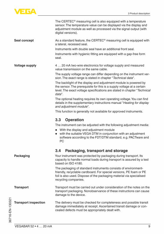
Fig. 1: Example of a VEGABAR 52 with manometer connection G½ A according to EN 837 and plastic housing1 Housing cover with integrated display and adjustment module (optional)2 Housing with electronics3 Process fitting with measuring cell
Thenameplatecontainsthemostimportantdataforidentificationanduse of the instrument:
Scope of delivery
Constituent parts
Type plate
8
3 Product description
VEGABAR 52 • 4 … 20 mA
36716-EN-130321
21
13
10
543
67
89
11
12
14
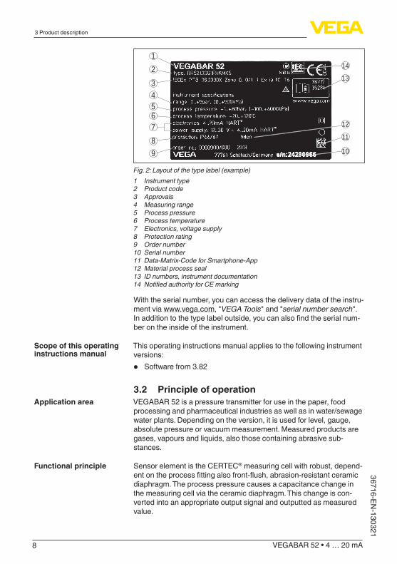
Fig. 2: Layout of the type label (example)1 Instrument type2 Product code3 Approvals4 Measuring range5 Process pressure6 Process temperature7 Electronics, voltage supply8 Protection rating9 Order number10 Serial number11 Data-Matrix-Code for Smartphone-App12 Material process seal13 ID numbers, instrument documentation14 Notified authority for CE marking
With the serial number, you can access the delivery data of the instru-ment via www.vega.com,"VEGA Tools"and"serial number search".Inadditiontothetypelabeloutside,youcanalsofindtheserialnum-ber on the inside of the instrument.
This operating instructions manual applies to the following instrument versions:
• Software from 3.82
3.2 Principle of operationVEGABAR 52 is a pressure transmitter for use in the paper, food processing and pharmaceutical industries as well as in water/sewage water plants. Depending on the version, it is used for level, gauge, absolute pressure or vacuum measurement. Measured products are gases, vapours and liquids, also those containing abrasive sub-stances.
Sensor element is the CERTEC® measuring cell with robust, depend-entontheprocessfittingalsofront-flush,abrasion-resistantceramicdiaphragm. The process pressure causes a capacitance change in the measuring cell via the ceramic diaphragm. This change is con-verted into an appropriate output signal and outputted as measured value.
Scope of this operating instructions manual
Application area
Functional principle
9
3 Product description
VEGABAR 52 • 4 … 20 mA
3671
6-EN
-130
321
The CERTEC® measuring cell is also equipped with a temperature sensor. The temperature value can be displayed via the display and adjustment module as well as processed via the signal output (with digital versions).
As a standard feature, the CERTEC® measuring cell is equipped with a lateral, recessed seal.Instruments with double seal have an additional front seal.Instrumentswithhygienicfittingareequippedwithagap-freeformseal.
4 … 20 mA two-wire electronics for voltage supply and measured value transmission on the same cable.Thesupplyvoltagerangecandifferdependingontheinstrumentver-sion.Theexactrangeisstatedinchapter"Technical data".The backlight of the display and adjustment module is powered by the sensor. The prerequisite for this is a supply voltage at a certain level.Theexactvoltagespecificationsarestatedinchapter"Technical data".Theoptionalheatingrequiresitsownoperatingvoltage.Youcanfinddetailsinthesupplementaryinstructionsmanual"Heating for display and adjustment module".This function is generally not available for approved instruments.
3.3 OperationThe instrument can be adjusted with the following adjustment media:
• With the display and adjustment module• with the suitable VEGA DTM in conjunction with an adjustment
software according to the FDT/DTM standard, e.g. PACTware and PC
3.4 Packaging, transport and storageYour instrument was protected by packaging during transport. Its capacity to handle normal loads during transport is assured by a test based on ISO 4180.The packaging of standard instruments consists of environment-friendly, recyclable cardboard. For special versions, PE foam or PE foil is also used. Dispose of the packaging material via specialised recycling companies.
Transport must be carried out under consideration of the notes on the transport packaging. Nonobservance of these instructions can cause damage to the device.
The delivery must be checked for completeness and possible transit damage immediately at receipt. Ascertained transit damage or con-cealed defects must be appropriately dealt with.
Seal concept
Voltage supply
Packaging
Transport
Transport inspection

10
3 Product description
VEGABAR 52 • 4 … 20 mA
36716-EN-130321
Uptothetimeofinstallation,thepackagesmustbeleftclosedandstored according to the orientation and storage markings on the outside.Unlessotherwiseindicated,thepackagesmustbestoredonlyunderthe following conditions:
• Not in the open• Dry and dust free• Not exposed to corrosive media• Protected against solar radiation• Avoiding mechanical shock and vibration
• Storageandtransporttemperatureseechapter"Supplement - Technical data - Ambient conditions"
• Relative humidity 20 … 85 %
3.5 Accessories and replacement partsThe display and adjustment module PLICSCOM is used for measured value indication, adjustment and diagnosis. It can be inserted into the sensor and removed at any time.Youcanfindfurtherinformationintheoperatinginstructions"Display and adjustment module PLICSCOM"(Document-ID27835).
Flangesareavailableindifferentversionsaccordingtothefollowingstandards: DIN 2501, EN 1092-1, ANSI B 16.5, JIS B 2210-1984, GOST 12821-80.Youcanfindadditionalinformationinthesupplementaryinstructionsmanual"Flanges according to DIN-EN-ASME-JIS"(Document-ID31088).
The measuring instrument holder is used for wall/tube mounting of VEGABAR series 50 pressure transmitters and VEGAWELL 52 sus-pension pressure transmitters. Supplied reducers enable the adapta-tiontodifferentinstrumentdiameters.Thematerialusedis316L.
The protective cover protects the sensor housing against soiling and intense heat from solar radiation.Youwillfindadditionalinformationinthesupplementaryinstructionsmanual"Protective cover"(Document-ID34296).
The electronics module is a replacement part for pressure transmitter VEGABAR. One version is available for each type of signal output.Youfindfurtherinformationintheoperatinginstructions"Electronics module VEGABAR series 50 and 60 "(Document-ID30175).
Storage
Storage and transport temperature
Display and adjustment module
Flanges
Measuring instrument holder
Protective cover
Electronics module
11
4 Mounting
VEGABAR 52 • 4 … 20 mA
3671
6-EN
-130
321
4 Mounting
4.1 General instructionsMake sure that all parts of the instrument coming in direct contact with the process, especially the sensor element, process seal and processfitting,aresuitablefortheexistingprocessconditions,suchas process pressure, process temperature as well as the chemical properties of the medium.Youcanfindthespecificationsinchapter"Technical data"andonthenameplate.
Select an installation position you can easily reach for mounting and connectingaswellaslaterretrofittingofadisplayandadjustmentmodule. The housing can be rotated by 330° without the use of any tools. You can also install the display and adjustment module in four differentpositions(eachdisplacedby90°).
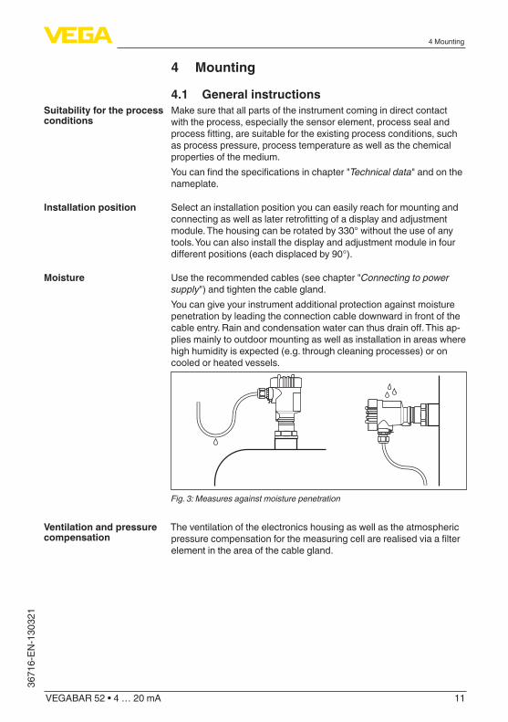
Usetherecommendedcables(seechapter"Connecting to power supply")andtightenthecablegland.You can give your instrument additional protection against moisture penetration by leading the connection cable downward in front of the cableentry.Rainandcondensationwatercanthusdrainoff.Thisap-plies mainly to outdoor mounting as well as installation in areas where high humidity is expected (e.g. through cleaning processes) or on cooled or heated vessels.
Fig. 3: Measures against moisture penetration
The ventilation of the electronics housing as well as the atmospheric pressurecompensationforthemeasuringcellarerealisedviaafilterelement in the area of the cable gland.
Suitability for the process conditions
Installation position
Moisture
Ventilation and pressure compensation

12
4 Mounting
VEGABAR 52 • 4 … 20 mA
36716-EN-130321
2
1
2
1
2
1
1
2
Fig. 4: Position of the filter element1 Filter element2 Blind plug
Caution:Duetothefiltereffect,thepressurecompensationistimedelayed.When opening/closing the housing cover quickly, the measured value can change for a period of approx. 5 s by up to 15 mbar.
Information:Makesurethatthefilterelementisalwaysfreeofbuildupduringoperation. A high-pressure cleaner may not be used for cleaning.With instrument versions in protection IP 66/IP 68, 1 bar, the ventila-tion is realised via the capillaries in the permanently connected cable. Thefilterelementisreplacedbyablindplug.
Higher process temperatures often mean also higher ambient temperatures. Make sure that the upper temperature limits stated in chapter"Technical data"fortheenvironmentoftheelectronicshous-ing and connection cable are not exceeded.
1
2
Fig. 5: Temperature ranges1 Process temperature2 Ambient temperature
Temperature limits

13
4 Mounting
VEGABAR 52 • 4 … 20 mA
3671
6-EN
-130
321
4.2 Mounting stepsFormountingVEGABAR52,aweldedsocketisrequired.Youcanfindthesecomponentsinthesupplementaryinstructionsmanual"Welded socket and seals".
Usethesealfittingbelongingtotheinstrument,orincaseofNPTconnections, a high-resistance sealing material.
→ Screw VEGABAR 52 into the welded socket. Tighten the hexagon ontheprocessfittingwithasuitablewrench.Wrenchsize,seechapter"Dimensions".
Warning:The housing must not be used to screw the instrument in! Applying tightening force can damage internal parts of the housing.
SealtheflangeconnectionsaccordingtoDIN/ANSIwithasuitable,resistant seal and mount VEGABAR 52 with suitable screws.
Usethesealsuitablefortherespectiveprocessfitting.Youcanfindthecomponentsinthesupplementaryinstructionsmanual"Welded socket and seals".
4.3 Mounting steps, external housing1. Mark the holes according to the following drilling template2. Depending on the mounting surface, fasten the wall mounting
plate with 4 screws
90 mm (3.54")
R 3,5 mm
(0.14")
3mm(0.12")
70 mm (2.76") 8 mm(0.32")
93 m
m (3
.66"
)
110
mm
(4.3
3")
Fig. 6: Drilling template - wall mounting plate
Welding the socket
Sealing/Screwing in threaded versions
Sealing/Screwing in flangeversions
Sealing/Screwing in hygienicfittings
Wall mounting

14
4 Mounting
VEGABAR 52 • 4 … 20 mA
36716-EN-130321
Tip:Mount the wall mounting plate so that the cable entry of the socket housing points downward. The socket housing can be displaced by 180° to the wall mounting plate.
Warning:The four screws of the socket housing must only be hand screwed. A torque > 5 Nm (3.688 lbf ft) can damage the wall mounting plate.

15
5 Connecting to power supply
VEGABAR 52 • 4 … 20 mA
3671
6-EN
-130
321
5 Connecting to power supply
5.1 Preparing the connectionAlways keep in mind the following safety instructions:
• Connect only in the complete absence of line voltage• If overvoltage surges are expected, overvoltage arresters should
be installed
Tip:We recommend using VEGA overvoltage arresters B63-48 and ÜSB 62-36G.X.Inhazardousareasyoumusttakenoteoftherespectiveregulations,conformityandtypeapprovalcertificatesofthesensorsandpowersupply units.
Power supply and current signal are carried on the same two-wire cable.Thevoltagesupplyrangecandifferdependingontheinstru-ment version.Thedataforpowersupplyarespecifiedinchapter"Technical data".Provide a reliable separation between the supply circuit and the mains circuits according to DIN EN 61140 VDE 0140-1. The VEGA power supply units VEGATRENN 149A Ex, VEGASTAB 690 as well as all VEGAMETs and VEGASCANs meet this requirement.Keepinmindthefollowingadditionalfactorsthatinfluencetheoperat-ing voltage:
• Output voltage of the power supply unit can be lower under nomi-nal load (with a sensor current of 20.5 mA or 22 mA in case of fault message)
• Influenceofadditionalinstrumentsinthecircuit(seeloadvaluesinchapter"Technical data")
The instrument is connected with standard two-wire cable without screen. If electromagnetic interference is expected which is above the test values of EN 61326 for industrial areas, screened cable should be used.Usecablewithroundcross-section.Acableouterdiameterof5…9mm(0.2…0.35in)ensuresthesealeffectofthecablegland.Ifyouareusingcablewithadifferentdiameterorcross-section,exchange the seal or use a suitable cable gland.We generally recommend the use of screened cable for HART multi-drop mode.
On the instrument with cable entry ½ NPT and plastic housing there is ametallic½"threadedinsertmouldedintotheplastichousing.
Caution:No grease should be used when screwing the NPT cable gland or steel tube into the threaded insert. Standard grease can contain additives that corrode the connection between threaded insert and
Safety instructions
Voltage supply
Connection cable
Cablegland½NPT

16
5 Connecting to power supply
VEGABAR 52 • 4 … 20 mA
36716-EN-130321
housing.Thiswouldinfluencethestabilityoftheconnectionandthetightness of the housing.
If screened cable is necessary, connect the cable screen on both ends to ground potential. In the sensor, the screen must be connected directly to the internal ground terminal. The ground terminal on the outside of the housing must be connected to the potential equalisa-tion (low impedance).If potential equalisation currents are expected, the connection on the processing side must be made via a ceramic capacitor (e. g. 1 nF, 1500 V). The low-frequency potential equalisation currents are thus suppressed,buttheprotectiveeffectagainsthighfrequencyinterfer-ence signals remains.
Warning:Considerablepotentialdifferencesexistinsidegalvanicplantsaswellas vessels with cathodic corrosion protection. Very large equalisa-tioncurrentscanflowthroughthecablescreenwhenthescreenis grounded on both ends. To avoid this, the cable screen must be connected to ground potential only on one end (inside the switch-ing cabinet) in such applications. The cable screen must not be connected to the internal ground terminal in the sensor and the outer ground terminal on the housing not to potential equalisation!
Information:Themetallicpartsoftheinstrument(transmitter,processfitting,etc.)are conductively connected with the inner and outer ground terminal on the housing. This connection exists either as a direct metallic contact or via the shielding of the special connection cable on instru-mentswithexternalelectronics.Youcanfindspecificationsonthepo-tentialconnectionswithintheinstrumentinchapter"Technical data".Take note of the corresponding installation regulations for Ex applica-tions. In particular, make sure that no potential equalisation currents flowoverthecablescreen.Incaseofgroundingonbothsidesthiscan be achieved by the use of a capacitor or a separate potential equalisation.
5.2 Connection procedureProceed as follows:1. Unscrewthehousingcover2. If a display and adjustment module is installed, remove it by turn-
ing it to the left.3. Loosen compression nut of the cable entry4. Remove approx. 10 cm of the cable mantle, strip approx. 1 cm
insulation from the individual wires5. Insert the cable into the sensor through the cable entry6. Lift the opening levers of the terminals with a screwdriver (see
following illustration)7. Insert the wire ends into the open terminals according to the wir-
ing plan
Cable screening and grounding
Single/Double chamber housing

17
5 Connecting to power supply
VEGABAR 52 • 4 … 20 mA
3671
6-EN
-130
321
8. Press down the opening levers of the terminals, you will hear the terminal spring closing
9. Check the hold of the wires in the terminals by lightly pulling on them
10. Connect the screen to the internal ground terminal, connect the outer ground terminal to potential equalisation
11. Tighten the compression nut of the cable entry. The seal ring must completely encircle the cable
12. Screw the housing cover back onTheelectricalconnectionishencefinished.
Fig. 7: Connection steps 6 and 7
5.3 Wiring plan, single chamber housingThe following illustrations apply to the non-Ex as well as to the Ex-ia version.

18
5 Connecting to power supply
VEGABAR 52 • 4 … 20 mA
36716-EN-130321
2
1
Display4...20mA
1 2
Fig. 8: Electronics and connection compartment, single chamber housing1 Spring-loaded terminals for voltage supply2 Ground terminal for connection of the cable screen
1
1 2
4...20mADisplay
Fig. 9: Wiring plan, single chamber housing1 Voltage supply/Signal output
5.4 Wiring plan - version IP 66/IP 68, 1 bar
1
2
Fig. 10: Wire assignment, connection cable1 brown (+) and blue (-) to power supply or to the processing system2 Shielding
Electronics and connec-tion compartment
Wiring plan
Wire assignment, con-nection cable

19
5 Connecting to power supply
VEGABAR 52 • 4 … 20 mA
3671
6-EN
-130
321
5.5 Wiring plan, external housing with version IP 68
Fig. 11: VEGABAR 52 in IP 68 version 25 bar and axial cable outlet, external housing
1 2 3 4
63
41
2
5
Fig. 12: Connection of the sensor in the housing socket1 Brown2 Blue3 Yellow4 White5 Shielding6 Breather capillaries
Overview
Terminal compartment, housing socket

20
5 Connecting to power supply
VEGABAR 52 • 4 … 20 mA
36716-EN-130321
2
3
Display4...20mA
1 21
Fig. 13: Electronics and connection compartment1 Spring-loaded terminals for voltage supply2 Ground terminal for connection of the cable screen3 Cable gland to the sensor
1
1 2
4...20mADisplay
Fig. 14: Wiring plan external electronics1 Voltage supply/Signal output
5.6 Switch-on phaseAfter connecting VEGABAR 52 to power supply or after a voltage recurrence, the instrument carries out a self-check for approx. 30 seconds:
• Internal check of the electronics• Indicationoftheinstrumenttype,thefirmwareaswellasthesen-
sor TAGs (sensor designation)• Outputsignaljumpsbriefly(approx.10seconds)tothesetfault
current
Then the corresponding current is outputted to the cable (the value corresponds to the actual level as well as the settings already carried out, e.g. factory setting).
Electronics and connec-tion compartment for power supply
Wiring plan external electronics
Switch-on phase

21
6 Set up with the display and adjustment module PLICSCOM
VEGABAR 52 • 4 … 20 mA
3671
6-EN
-130
321
6 Set up with the display and adjustment module PLICSCOM
6.1 Short descriptionThe display and adjustment module is used for measured value display, adjustment and diagnosis. It can be mounted in the following housing versions and instruments:
• All continuously measuring sensors in single as well as double chamber housing (optionally in the electronics or connection compartment)
• External display and adjustment unit
Note:Youcanfinddetailedinformationontheadjustmentintheoperatinginstructionsmanual"Display and adjustment module".
6.2 Insert display and adjustment moduleThe display and adjustment module can be inserted into the sensor and removed again at any time. It is not necessary to interrupt the power supply.Proceed as follows:1. Unscrewthehousingcover2. Place the display and adjustment module in the desired position
ontheelectronics(youcanchooseanyoneoffourdifferentposi-tions - each displaced by 90°)
3. Press the display and adjustment module onto the electronics and turn it to the right until it snaps in.
4. Screw housing cover with inspection window tightly back onRemoval is carried out in reverse order.The display and adjustment module is powered by the sensor, an ad-ditional connection is not necessary.
Mount/Dismount display and adjustment module
22
6 Set up with the display and adjustment module PLICSCOM
VEGABAR 52 • 4 … 20 mA
36716-EN-130321
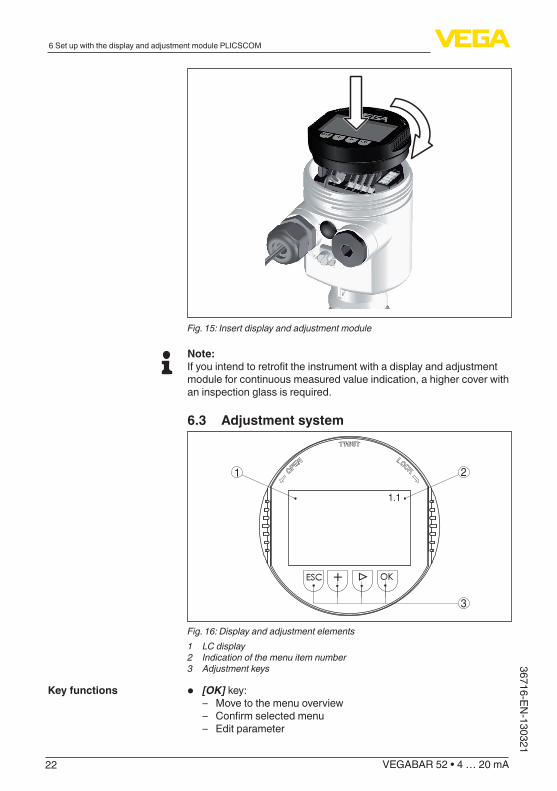
Fig. 15: Insert display and adjustment module
Note:Ifyouintendtoretrofittheinstrumentwithadisplayandadjustmentmodule for continuous measured value indication, a higher cover with an inspection glass is required.
6.3 Adjustment system
2
3
1
1.1
Fig. 16: Display and adjustment elements1 LC display2 Indication of the menu item number3 Adjustment keys
• [OK] key: – Move to the menu overview – Confirmselectedmenu – Edit parameter
Key functions

23
6 Set up with the display and adjustment module PLICSCOM
VEGABAR 52 • 4 … 20 mA
3671
6-EN
-130
321
– Save value
• [->] key to select: – Menu change – Select list entry – Select editing position
• [+] key: – Change value of the parameter
• [ESC] key: – interrupt input – Jump to next higher menu
The sensor is adjusted via the four keys of the display and adjust-ment module. The LC display indicates the individual menu items. The functions of the individual keys are shown in the above illustration. Approx. 10 minutes after the last pressing of a key, an automatic reset tomeasuredvalueindicationistriggered.Anyvaluesnotconfirmedwith [OK] will not be saved.
6.4 Setup stepsVEGABAR 52 can be used for level as well as for process pressure measurement. Default setting is level measurement. The mode can be changed in the adjustment menu.Dependingontheapplicationonlytherespectivesubchapter"Levelorprocesspressuremeasurement"isofimportance.There,youfindthe individual adjustment steps.
Level measurement
Set up VEGABAR 52 in the following sequence:1. Selecting adjustment unit/density unit2. Carry out a position correction3. Carry out min. adjustment4. Carry out max. adjustmentInthemenuitem"Adjustment unit"youselectthephysicalunitinwhich the adjustment should be carried out, e.g. mbar, bar, psi…Thepositioncorrectioncompensatestheinfluenceofthemountingpositionorstaticpressureonthemeasurement.Itdoesnotinfluencethe adjustment values.
Information:The steps 1, 3 and 4 are not necessary for instruments which are alreadypresetaccordingtocustomerspecifications!Youcanfindthedataonthetypelabelontheinstrumentorinthemenu items of the min./max. adjustment.The display and adjustment module enables the adjustment without fillingorpressure.Thankstothis,youcancarryoutyoursettingsalready in the workshop without the instrument having to be installed.
Adjustment system
Level or process pres-sure measurement
Parameter adjustment "Level measurement"

24
6 Set up with the display and adjustment module PLICSCOM
VEGABAR 52 • 4 … 20 mA
36716-EN-130321
The actual measured value is also displayed in the menu items for min./max. adjustment.
In this menu item you select the adjustment unit as well as the unit for the temperature indication in the display.To select the adjustment unit (in the example switching over from bar to mbar), proceed as follows:1)
1. Push the [OK] button in the measured value display, the menu overview is displayed.
▶Basic adjustmentDisplayDiagnosticsServiceInfo
2. Confirmthemenu"Basic adjustment"with[OK], the menu item "Unit"willbedisplayed.
UnitUnitofmeasurement
bar▼Temperature unit
°C▼
3. Activate the selection with [OK]andselect"Units of measure-ment with [->].
4. Activate the selection with [OK] and select the requested unit with [->] (in the example mbar).
5. Confirmwith[OK] and move to position correction with [->].The adjustment unit is thus switched over from bar to mbar.
Information:When switching over to adjustment in a height unit (in the example from bar to m), the density also has to be entered.Proceed as follows:1. Push the [OK] button in the measured value display, the menu
overview is displayed.2. Confirmthemenu"Basic adjustment"with[OK], the menu item
"Units of measurement"willbedisplayed.3. Activate the selection with [OK] and select the requested unit with
[->] (in the example m).4. Confirmwith[OK],thesubmenu"Density unit"appears.
Unitofmeasurement
Density unit▶ kg/dm³
pcf
5. Select the requested unit, e.g. kg/dm³ with [->]andconfirmwith[OK],thesubmenu"Density"appears.
Unitofmeasurement
Select unit
1) Selection options: mbar, bar, psi, Pa, kPa, MPa, inHg, mmHg, inH2O, mmH2O.

25
6 Set up with the display and adjustment module PLICSCOM
VEGABAR 52 • 4 … 20 mA
3671
6-EN
-130
321
Density0001000kg/dm³
6. Enter the requested density value with [->] and [+],confirmwith[OK] and move to position correction with [->].
The adjustment unit is thus switched over from bar to m.Proceed as follows to select the temperature unit:2)
1. Activate the selection with [OK]andselect"Temperature unit with [->].
2. Activate the selection with [OK] and select the requested unit with [->] (e.g. °F).
3. Confirmwith[OK].The temperature unit is hence switched over from °C to °F.
Proceed as follows:1. Activateinthemenuitem"Position correction"theselectionwith
[OK].Position correctionOffset
P
=+0000 mbar53 mbar
2. Select with [->], e.g. to accept actual measured value.Position correctionAccept current measured value?
▶AcceptEdit
3. Confirmwith[OK]andmovetomin.(zero)adjustmentwith[->].
Proceed as follows:1. Editthe%valueinthemenuitem"Min. adjustment"with[OK].
Min. adjustment+000.0 %=+0000.0 mbar
0000.0 mbar
2. Set the requested percentage value with [+] and [->].3. Confirmwith[OK] and edit the requested mbar value.4. Set the requested mbar value with [+] and [->].5. Confirmwith[+] and move to max. adjustment with [->].Themin.adjustmentisfinished.
Information:Foranadjustmentwithfilling,simplyentertheactualmeasuredvalueindicated at the bottom of the display.
Carry out a position cor-rection
Carry out min. adjustment
2) Selection options: °C, °F.
26
6 Set up with the display and adjustment module PLICSCOM
VEGABAR 52 • 4 … 20 mA
36716-EN-130321
Iftheadjustmentrangesareexceeded,themessage"Outside param-eter limits"appears.Theeditingprocedurecanbeabortedwith[ESC] or the displayed limit value can be accepted with [OK].
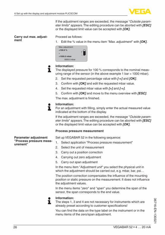
Proceed as follows:1. Editthe%valueinthemenuitem"Max. adjustment"with[OK].
Max. adjustment+100.0 %=+1000.0 mbar
0000.0 mbar
Information:The displayed pressure for 100 % corresponds to the nominal meas-uring range of the sensor (in the above example 1 bar = 1000 mbar).2. Set the requested percentage value with [->] and [OK].3. Confirmwith[OK] and edit the requested mbar value.4. Set the requested mbar value with [+] and [->].5. Confirmwith[OK] and move to the menu overview with [ESC].Themax.adjustmentisfinished.
Information:Foranadjustmentwithfilling,simplyentertheactualmeasuredvalueindicated at the bottom of the display.Iftheadjustmentrangesareexceeded,themessage"Outside param-eter limits"appears.Theeditingprocedurecanbeabortedwith[ESC] or the displayed limit value can be accepted with [OK].
Process pressure measurement
Set up VEGABAR 52 in the following sequence:1. Selectapplication"Processpressuremeasurement"2. Select the unit of measurement3. Carry out a position correction4. Carryingoutzeroadjustment5. Carry out span adjustmentInthemenuitem"Adjustment unit"youselectthephysicalunitinwhich the adjustment should be carried out, e.g. mbar, bar, psi…Thepositioncorrectioncompensatestheinfluenceofthemountingpositionorstaticpressureonthemeasurement.Itdoesnotinfluencethe adjustment values.Inthemenuitems"zero"and"span"youdeterminethespanofthesensor, the span corresponds to the end value.
Information:The steps 1, 3 and 4 are not necessary for instruments which are alreadypresetaccordingtocustomerspecifications!Youcanfindthedataonthetypelabelontheinstrumentorinthemenuitemsofthezero/spanadjustment.
Carry out max. adjust-ment
Parameter adjustment "Process pressure meas-urement"

27
6 Set up with the display and adjustment module PLICSCOM
VEGABAR 52 • 4 … 20 mA
3671
6-EN
-130
321
The display and adjustment module enables the adjustment without fillingorpressure.Thankstothis,youcancarryoutyoursettingsalready in the workshop without the instrument having to be installed.The actual measured value is displayed in addition to the menu items forzero/spanadjustment.
VEGABAR52ispresettoapplication"Levelmeasurement".Proceedasfollowswhenswitchingovertoapplication"Processpressuremeasurement":1. Push the [OK] button in the measured value display, the menu
overview is displayed.2. Selectthemenu"Service"with[->]andconfirmwith[OK].
Basic adjustmentDisplayDiagnostics
▶ServiceInfo
3. Selectthemenuitem"Application"with[->] and edit with [OK].
Warning:Notethewarning:"Output can change".4. Select with [->]"OK"andconfirmwith[OK].5. Select"Process pressure"fromthelistandconfirmwith[OK].
In this menu item you select the adjustment unit as well as the unit for the temperature indication in the display.To select the adjustment unit (in the example switching over from bar to mbar), proceed as follows:3)
1. Push the [OK] button in the measured value display, the menu overview is displayed.
▶Basic adjustmentDisplayDiagnosticsServiceInfo
2. Confirmthemenu"Basic adjustment"with[OK], the menu item "Unit"willbedisplayed.
UnitUnitofmeasurement
bar▼Temperature unit
°C▼
3. Activate the selection with [OK]andselect"Units of measure-ment with [->].
4. Activate the selection with [OK] and select the requested unit with [->] (in the example mbar).
5. Confirmwith[OK] and move to position correction with [->].
Select application "Pro-cess pressure measure-ment"
Select unit
3) Selection options: mbar, bar, psi, Pa, kPa, MPa, inHg, mmHg, inH2O, mmH2O.
28
6 Set up with the display and adjustment module PLICSCOM
VEGABAR 52 • 4 … 20 mA
36716-EN-130321
The adjustment unit is thus switched over from bar to mbar.Proceed as follows to select the temperature unit:4)
1. Activate the selection with [OK]andselect"Temperature unit with [->].
2. Activate the selection with [OK] and select the requested unit with [->] (e.g. °F).
3. Confirmwith[OK].The temperature unit is hence switched over from °C to °F.
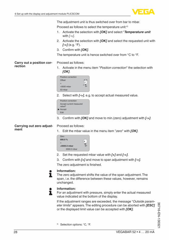
Proceed as follows:1. Activateinthemenuitem"Position correction"theselectionwith
[OK].Position correctionOffset
P
=+0000 mbar53 mbar
2. Select with [->], e.g. to accept actual measured value.Position correctionAccept current measured value?
▶AcceptEdit
3. Confirmwith[OK]andmovetomin.(zero)adjustmentwith[->].
Proceed as follows:1. Editthembarvalueinthemenuitem"zero"with[OK].
Zero000.0 %
P
=+0000.0 mbar
0000.0 mbar
2. Set the requested mbar value with [+] and [->].3. Confirmwith[+] and move to span adjustment with [->].Thezeroadjustmentisfinished.
Information:Thezeroadjustmentshiftsthevalueofthespanadjustment.Thespan,i.e.thedifferencebetweenthesevalues,however,remainsunchanged.
Information:For an adjustment with pressure, simply enter the actual measured value indicated at the bottom of the display.Iftheadjustmentrangesareexceeded,themessage"Outside param-eter limits"appears.Theeditingprocedurecanbeabortedwith[ESC] or the displayed limit value can be accepted with [OK].
Carry out a position cor-rection
Carrying out zero adjust-ment
4) Selection options: °C, °F.

29
6 Set up with the display and adjustment module PLICSCOM
VEGABAR 52 • 4 … 20 mA
3671
6-EN
-130
321
Proceed as follows:1. Editthembarvalueinthemenuitem"span"with[OK].
Span100.0 %
P
=+1000.0 mbar
0000.0 mbar
Information:The displayed pressure for 100 % corresponds to the nominal meas-uring range of the sensor (in the above example 1 bar = 1000 mbar).2. Set the requested mbar value with [->] and [OK].3. Confirmwith[OK] and move to the menu overview with [ESC].Thespanadjustmentisfinished.
Information:For an adjustment with pressure, simply enter the actual measured value indicated at the bottom of the display.Iftheadjustmentrangesareexceeded,themessage"Outside param-eter limits"appears.Theeditingprocedurecanbeabortedwith[ESC] or the displayed limit value can be accepted with [OK].
A linearisation is necessary for all vessels in which the vessel volume doesnotincreaselinearlywiththelevel-e.g.inahorizontalcylindri-cal or spherical tank - and the indication or output of the volume is required. Corresponding linearisation curves are preprogrammed for these vessels. They represent the correlation between the level per-centage and vessel volume. By activating the appropriate curve, the volume percentage of the vessel is displayed correctly. If the volume should not be displayed in percent but e.g. in l or kg, a scaling can be alsosetinthemenuitem"Display".
Linearizationcurve
Linear
Enter the requested parameters via the appropriate keys, save your settings and jump to the next menu item with the [->] key.
Caution:Note the following if the VEGABAR 52 with corresponding approval is usedaspartofanoverfillprotectionsystemaccordingtoWHG(WaterResources Act):Ifalinearizationcurveisselected,themeasuringsignalisnolongerlinearly proportional to the level. This must be taken into consideration by the user, particularly when setting the switching point on the limit signal indicator.
This function enables reading out parameter adjustment data as well as writing parameter adjustment data into the sensor via the display and adjustment module. A description of the function is available in theoperatinginstructionsmanual"Display and adjustment module".
Carry out span adjust-ment
Linearization curve
Copy sensor data

30
6 Set up with the display and adjustment module PLICSCOM
VEGABAR 52 • 4 … 20 mA
36716-EN-130321
The following data are read out or written with this function:
• Measured value presentation• Adjustment• Damping• Linearizationcurve• Sensor-TAG• Displayed value• Display unit• Scaling• Current output• Unitofmeasurement• Language
The following safety-relevant data are not read out or written:
• SIL• HART mode5)
• PIN• Application
Copy sensor data
Copy sensor data?
The reset function resets all parameters adjusted by the user to the delivery status and the peak values to the actual values.
Reset
Select reset?▼
ResetBasic adjustmentPeak value, measured valuePeak value, temperature
Basic adjustmentThe"Reset""Basic adjustment"resetsthevaluesofthefollowingmenu items:
Menu section Function Resetvalue
Basic settings Zero/Min. adjustment Measuring range begin
Span/Max. adjustment Measuring range end
Density 1 kg/l
Density unit kg/l
Damping 1 s
Linearization Linear
Sensor-TAG Sensor
Reset
5) With instruments with signal output 4 … 20 mA/HART

31
6 Set up with the display and adjustment module PLICSCOM
VEGABAR 52 • 4 … 20 mA
3671
6-EN
-130
321
Menu section Function Resetvalue
Display Displayed value 1 bar
Displayed value 2 %
Display unit Volume/l
Scaling 0.00 to 100.0
Decimal point indication 8888.8
Service Current output - charac-teristics
4 … 20 mA
Current output - failure < 3.6 mA
Current output - min. current
3.8 mA
Current output - max. current
20.5 mA
The values of the following menu items are notresetwith"Reset:
Menu section Function Resetvalue
Basic settings Unitofmeasurement No reset
Temperature unit No reset
Position correction No reset
Display Backlight No reset
Service Language No reset
Application No reset
Peak valueThe min. and max. temperature or pressure values are each reset to the actual value.
Additional adjustment and diagnosis options such as e.g. scaling, simulation or trend curve presentation are shown in the following menuschematic.Youwillfindadetaileddescriptionofthesemenuitemsintheoperatinginstructionsmanual"Display and adjustment module".
6.5 Menu schematicInformation:Depending on the version and application, the highlighted menu windows may not always be available.
Optional settings

32
6 Set up with the display and adjustment module PLICSCOM
VEGABAR 52 • 4 … 20 mA
36716-EN-130321
Basic adjustment
▶Basic adjustment 1DisplayDiagnosticsServiceInfo
Unit 1.1Unitofmeasurement
bar ▼Temperature unit
°C ▼
Position correction 1.2Offset
P
=0.2 mbar0000 mbar
Min. adjustment 1.3000.0 %=0.0 mbar
0.0 mbar
Max. adjustment 1.4100.00 %=100.00 mbar
0.0 mbar
Damping 1.5
1 s
Linearizationcurve 1.6
Linear ▼
Sensor-TAG 1.7
Sensor
Display
Basic adjustment 2▶Display
DiagnosticsServiceInfo
Displayed value 2.1
Pressure ▼
Displayed value ▼ 2.1
Scaled
Display unit 2.2
Volume ▼l ▼
Scaling 2.30 % = 0.0l100 % = 100.0l
Backlight 2.4
Switchedoff▼
Diagnostics
Basic adjustment 3Display
▶DiagnosticsServiceInfo
Peak value 3.1p-min.: -5.8 mbarp-max.: 167.5 mbarT-min.: -12.5 °CT-max.: +85.5 °C
Sensor status 3.2
OK
Trend curve 3.3
Start trend curve?
33
6 Set up with the display and adjustment module PLICSCOM
VEGABAR 52 • 4 … 20 mA
3671
6-EN
-130
321
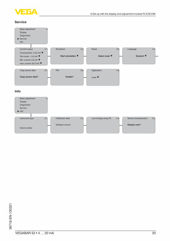
Service
Basic adjustment 4DisplayDiagnostics
▶ServiceInfo
Current output 4.1
Characteristic: 4-20 mA ▼Fail.mode: < 3.6 mA ▼Min. current: 3.8 mA ▼max. current: 20.5 mA ▼
Simulation 4.2
Start simulation ▼
Reset 4.3
Select reset ▼
Language 4.4
Deutsch ▼
Copy sensor data 4.7
Copy sensor data?
PIN 4.8
Enable?
Application 4.9
Level ▼
Info
Basic adjustment 5DisplayDiagnosticsService
▶ Info
Instrument type 5.1
Serial number
Calibration date 5.2
Software version
Last change using PC 5.3 Sensor characteristics 5.4
Display now?
34
7 Set up with PACTware and other adjustment programs
VEGABAR 52 • 4 … 20 mA
36716-EN-130321
7 Set up with PACTware and other adjustment programs
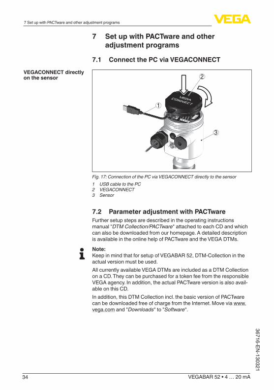
7.1 ConnectthePCviaVEGACONNECT
3
1
2
Fig. 17: Connection of the PC via VEGACONNECT directly to the sensor1 USB cable to the PC2 VEGACONNECT3 Sensor
7.2 Parameter adjustment with PACTwareFurther setup steps are described in the operating instructions manual"DTM Collection/PACTware"attachedtoeachCDandwhichcan also be downloaded from our homepage. A detailed description is available in the online help of PACTware and the VEGA DTMs.
Note:Keep in mind that for setup of VEGABAR 52, DTM-Collection in the actual version must be used.All currently available VEGA DTMs are included as a DTM Collection on a CD. They can be purchased for a token fee from the responsible VEGA agency. In addition, the actual PACTware version is also avail-able on this CD.In addition, this DTM Collection incl. the basic version of PACTware can be downloaded free of charge from the Internet. Move via www.vega.comand"Downloads"to"Software".
VEGACONNECTdirectlyon the sensor

35
8Maintenanceandfaultrectification
VEGABAR 52 • 4 … 20 mA
3671
6-EN
-130
321
8 Maintenanceandfaultrectification
8.1 MaintainIf the instrument is used properly, no special maintenance is required in normal operation.Insomeapplications,productbuilduponthediaphragmcaninfluencethe measuring result. Depending on the sensor and application, take precautions to ensure that heavy buildup, and especially a hardening thereof, is avoided.
If necessary, clean the diaphragm. Make sure that the materials are resistanttothecleaningprocess,seeresistancelistunder"Services"on"www.vega.com".Thewidevarietyofapplicationsofchemicalseals makes special cleaning instructions necessary for each applica-tion. Please ask the VEGA agency serving you.
8.2 RectifyfaultsThe operator of the system is responsible for taking suitable meas-ures to rectify faults.
VEGABAR52offersmaximumreliability.Nevertheless,faultscanoc-cur during operation. These may be caused by the following, e.g.:
• Sensor• Process• Voltage supply• Signal processing
Thefirstmeasurestobetakenaretochecktheoutputsignalsaswellas to evaluate the error messages via the display and adjustment module. The procedure is described below. Further comprehensive diagnostics can be carried out on a PC with the software PACTware and the suitable DTM. In many cases, the causes can be determined andthefaultsrectifiedthisway.
Should these measures not be successful, please call in urgent cases the VEGA service hotline under the phone no. +49 1805 858550.The hotline is available to you 7 days a week round-the-clock. Since weofferthisserviceworld-wide,thesupportisonlyavailableintheEnglish language. The service is free of charge, only the standard telephone costs will be charged.
Connect a handheld multimeter in the suitable measuring range ac-cording to the wiring plan.
Maintenance
Cleaning
Reactionwhenmalfunc-tions occur
Failure reasons
Faultrectification
24 hour service hotline
Check the 4 … 20 mA signal

36
8Maintenanceandfaultrectification
VEGABAR 52 • 4 … 20 mA
36716-EN-130321
Error code Cause Rectification
4 … 20 mA signal not stable
Levelfluctuations – Set the integration time via the display and adjustment module or PACTware
No atmospheric pres-sure compensation
– Check the pressure compensation inthehousingandcleanthefilterelement, if necessary
4 … 20 mA signal miss-ing
Connection to volt-age supply wrong
– Check connection according to chapter"Connection steps"andif necessary, correct according to chapter"Wiring plan"
No power supply – Check cables for breaks; repair if necessary
Operating voltage too low or load resist-ance too high
– Check, adapt if necessary
Current sig-nal greater than 22 mA or less than 3.6 mA
Electronics module or measuring cell de-fective
– Exchange the instrument or send it in for repair
In Ex applications, the regulations for the wiring of intrinsically safe circuits must be observed.
Error code Cause Rectification
E013 no measured value available6)
– Exchange the instrument or send it in for repair
E017 Adjustment span too small
– repeatwithmodifiedvalues
E036 no operable sensor software
– Carry out a software update or send instrument for repair
E041 Hardware error – Exchange the instrument or send it in for repair
Depending on the reason for the fault and the measures taken, the stepsdescribedinchapter"Set up"mayhavetobecarriedoutagain.
8.3 Calculation of total deviation (according to DIN16086)
The total deviation Ftotal according to DIN 16086 is the sum of basic accuracy Fperf and longterm stability Fstab. Ftotal is also called maximum practical deviation or utility error.Ftotal= Fperf + Fstab
Fperf=√((FT)2 + (FKl)2)With the analogue signal output there is also the error of the current output Fa.
Error messages via the display and adjustment module
Reactionafterfaultrecti-fication
Total deviation
6) Fault message can also appear if the pressure is higher than the nominal range.

37
8Maintenanceandfaultrectification
VEGABAR 52 • 4 … 20 mA
3671
6-EN
-130
321
Fperf=√((FT)2 + (FKl)2 + (Fa)2)With:
• Ftotal: Total deviation• Fperf: Basic accuracy• Fstab: Long-term drift• FT:Temperaturecoefficient(influenceofmediumorambient
temperature)• FKl: Deviation• Fa: Error current output
Pressure measurement in the pipeline 8 bar (800 KPa)Product temperature 50 °C, hence within the compensated rangeVEGABAR 52 with measuring range 10 barCalculation of the set Turn Down: TD = 10 bar/8 bar, TD = 1.25
Basic accuracy digital output signal in percent:Fperf=√((FT)2 + (FKl)2)FT = (0.05 % + 0.1 % x TD)FKl= 0.075 %Fperf=√((0.05%+0.1%x1.25)2 + (0.075 %)2)Fperf = 0.19 %
Total deviation digital output signal in percent:Ftotal = Fperf + Fstab
Fstab = (0.1 % x TD)/yearFstab = (0.1 % x 1.25)/yearFstab = 0.125 %Ftotal = 0.19 % + 0.125 % = 0.315 %
Total deviation digital output signal absolute:Ftotal = 0.315 % x 8 bar/100 % = 25.2 mbar
Basic accuracy analogue output signal in percent:Fperf=√((FT)2 + (FKl)2 + (Fa)2)FT = (0.05 % + 0.1 % x TD)FKl= 0.075 %Fa = 0.15 %Fperf=√((0.05%+0.1%x1.25)2 + (0.075 %)2 + (0.15 %)2)Fperf = 0.24 %
Total deviation analogue output signal in percent:Ftotal = Fperf + Fstab
Fstab = (0.1 % x TD)/yearFstab = (0.1 % x 1.25)/yearFstab = 0.125 %Ftotal = 0.24 % + 0.125 % = 0.365 %
Example

38
8Maintenanceandfaultrectification
VEGABAR 52 • 4 … 20 mA
36716-EN-130321
Total deviation analogue output signal absolute:Ftotal = 0.365 % x 8 bar/100 % = 29.2 mbar
8.4 Exchanging the electronics moduleIn case of a defect, the electronics module can be exchanged by the user against an identical type. If no electronics module is available on side, the module can be ordered from the agency serving you.Ordering and exchange are possible with or without sensor serial number. The electronics module with serial number includes order-specific data such as factory setting, seal material etc. These are not included in the electronics module without serial number.The serial number is stated on the type label of VEGABAR 52 or on the delivery note.
8.5 Software updateThe software version of VEGABAR 52 can be determined as follows:
• on the type label of the electronics• Via the display and adjustment module• via PACTware
You can view all software histories on our website www.vega.com. Make use of this advantage and get registered for update information via e-mail.The following components are required to update the sensor soft-ware:
• Sensor• Voltage supply• VEGACONNECT• PC with PACTware• Currentsensorsoftwareasfile
At"www.vega.com/downloads"goto"Software".Selectunder"plics sensors and instruments","Firmware updates"therespectiveinstru-mentseriesandsoftwareversion.Loadthezipfileviatherightmousekeywith"Save target as"e.g.onthedesktopofyourPC.Movewiththerightmousekeytothefolderandselect"Extract all".Savetheextractedfiles,forexampleonthedesktop.
Connect the signal conditioning instrument to power supply and provide the connection from the PC to the instrument via the interface adapter.StartPACTwareandgoviathemenu"Project"totheVEGA project assistant.Select"USB"and"Set instruments online".Activatetheprojectassistantwith"Start".Theassistantestablishesthecon-nection automatically and opens the parameter adjustment window "Sensor # online parameter adjustment".Connectthisparameteradjustment window before you carry out further steps.
Select with the right mouse key the sensor in the project and go to "Additional function".Thenclickto"Software update".Thewindow"Sensor # software update"opens.PACTwarechecksnowthesensor
Load sensor software to PC
Prepare update
Load software into sen-sor
39
8Maintenanceandfaultrectification
VEGABAR 52 • 4 … 20 mA
3671
6-EN
-130
321
data and displays the actual hardware and software version of the sensor. This takes approximately 60 s.Pushthebutton"Update software"andselectthepreviouslyextractedhexfile.Thenthesoftwareupdatecanbestarted.Theadditionalfilesare installed automatically. Depending on the sensor, this procedure lastsupto1h.Thenthemessageappears""Software update suc-cessfully executed".
8.6 Instrument repairIf a repair is necessary, please proceed as follows:You can download a return form (23 KB) from our Internet homepage www.vega.comunder:"Downloads - Forms and certificates - Repair form".By doing this you help us carry out the repair quickly and without hav-ing to call back for needed information.
• Printandfilloutoneformperinstrument• Clean the instrument and pack it damage-proof• Attach the completed form and, if need be, also a safety data
sheet outside on the packaging• Please ask the agency serving you for the address of your return
shipment.Youcanfindtherespectivecontactdataonourwebsitewww.vega.comunder:"Company - VEGA worldwide"

40
9 Dismounting
VEGABAR 52 • 4 … 20 mA
36716-EN-130321
9 Dismounting
9.1 Dismounting stepsWarning:Before dismounting, be aware of dangerous process conditions such as e.g. pressure in the vessel, high temperatures, corrosive or toxic products etc.Takenoteofchapters"Mounting"and"Connecting to power supply"and carry out the listed steps in reverse order.
9.2 DisposalThe instrument consists of materials which can be recycled by spe-cialised recycling companies. We use recyclable materials and have designed the parts to be easily separable.
WEEE directive 2002/96/EGThis instrument is not subject to the WEEE directive 2002/96/EG and the respective national laws. Pass the instrument directly on to a spe-cialised recycling company and do not use the municipal collecting points. These may be used only for privately used products according to the WEEE directive.Correctdisposalavoidsnegativeeffectsonhumansandtheenviron-ment and ensures recycling of useful raw materials.Materials:seechapter"Technical data"If you have no way to dispose of the old instrument properly, please contact us concerning return and disposal.

41
10 Supplement
VEGABAR 52 • 4 … 20 mA
3671
6-EN
-130
321
10 Supplement
10.1 Technical dataGeneral dataParameter, pressure Gauge pressure, absolute pressure, vacuumMeasuring principle Ceramic-capacitive, dry measuring cellCommunication interface I²C bus
Materials and weightsMaterial 316L corresponds to 1.4404 or 1.4435Materials, wetted parts
Ʋ Processfitting 316L, PVDF, Alloy C-22, Alloy C-276, Duplex 1.4462, Titanium Grade 2
Ʋ Diaphragm sapphire ceramic® (99.9 % oxide ceramic) Ʋ Joining material diaphragm/Basic ele-ment measuring cell
Glass solder
Ʋ Measuring cell seal FKM (VP2/A, A+P70.16), EPDM (A+P 75.5/KW75F), FFKM(Kalrez6375,PerlastG75S,PerlastG75B)
Materialsealprocessfitting Ʋ Thread G½ (EN 837) Klingersil C-4400 Ʋ Thread G1½ (DIN 3852-A) Klingersil C-4400 Ʋ M44 x 1.25 (DIN 13) FKM, FFKM, EPDM
Surfacequalityhygienicfittings,typ. Ra < 0.8 µm Ʋ Surface quality, typ.
Materials, non-wetted parts Ʋ Electronics housing Plastic PBT (polyester), Alu die-casting powder-coated,
316L Ʋ External housing plastic PBT (Polyester), 316L Ʋ Socket, wall mounting plate external housing
plastic PBT (Polyester), 316L
Ʋ Seal between socket and wall mount-ing plate
EPDM(fixedconnected)
Ʋ Seal below wall mounting plate EPDM (only with 3A approval) Ʋ Seal, housing cover NBR (stainless steel housing), silicone (Alu/plastic hous-
ing) Ʋ Inspection window in housing cover for display and adjustment module
Polycarbonate(UL-746-Clisted)
Ʋ Ground terminal 316Ti/316L Ʋ Ohmic contact Betweengroundterminalandprocessfitting Ʋ Connection cable between transmitter and external electronics housing with IP 68 version
PUR
Ʋ Type label support on connection cable
PE hard

42
10 Supplement
VEGABAR 52 • 4 … 20 mA
36716-EN-130321
Ʋ Connection cable with IP 68 1 bar version
PE
Weight approx. 0.8 … 8 kg (1.764 … 17.64 lbs), depending on process fitting
Output variableOutput signal 4 … 20 mASignal resolution 1.6 µAFailure signal output current mA value unchanged 20.5 mA, 22 mA, < 3.6 mA (adjust-
able)Max. output current 22 mALoad see load diagram under Power supplyMetNAMURrecommendation NE 43
Dynamic behaviour outputRun-up time approx. 10 s
90 %
100 %
10 %
t tT At
tS
21
Fig. 18: Sudden change of the process variable. tT: dead time; tA: rise time; tS: jump response time1 Process variable2 Output signal
Dead time ≤150msRise time ≤100ms(10…90%)Step response time ≤250ms(ti:0s,10…90%)Damping (63 % of the input variable) 0 … 999 s, adjustable
Input variableAdjustmentAdjustment range of the min./max. adjustment relating to the nominal measuring range:
Ʋ Percentage value -10 … 110 % Ʋ Pressure value -20 … 120 %
Adjustmentrangeofthezero/spanadjustmentrelatingtothenominalmeasuringrange: Ʋ zero -20 … +95 %

43
10 Supplement
VEGABAR 52 • 4 … 20 mA
3671
6-EN
-130
321
Ʋ span -120 … +120 %7)
Ʋ Differencebetweenzeroandspan max. 120 % of the nominal rangeRecommended max. turn down 10 : 1 (no limitation)Nominalmeasuringrangesandoverloadcapabilityinbar/kPaThespecificationsareonlyanoverviewandrefertothemeasuringcell.Limitationsduetothema-terialandversionoftheprocessfittingarepossible.Thespecificationsonthenameplateapply.
Nominalrange Overload capacity, max. pressure
Overload capacity, min. pres-sure
Gauge pressure
0 … +0.1 bar/0 … +10 kPa +15 bar/+1500 kPa -0.2 bar/-20 kPa
0 … +0.2 bar/0 … +20 kPa +20 bar/+2000 kPa -0.4 bar/-40 kPa
0 … +0.4 bar/0 … +40 kPa +30 bar/+3000 kPa -0.8 bar/-80 kPa
0 … +1 bar/0 … +100 kPa +35 bar/+3500 kPa -1 bar/-100 kPa
0 … +2.5 bar/0 … +250 kPa +50 bar/+5000 kPa -1 bar/-100 kPa
0 … +5 bar/0 … +500 kPa +65 bar/+6500 kPa -1 bar/-100 kPa
0 … +10 bar/0 … +1000 kPa +90 bar/+9000 kPa -1 bar/-100 kPa
0 … +25 bar/0 … +2500 kPa +130 bar/+13000 kPa -1 bar/-100 kPa
0 … +60 bar/0 … +6000 kPa +200 bar/+20000 kPa -1 bar/-100 kPa
-1 … 0 bar/-100 … 0 kPa +35 bar/+3500 kPa -1 bar/-100 kPa
-1 … +1.5 bar/-100 … +150 kPa +50 bar/+5000 kPa -1 bar/-100 kPa
-1 … +5 bar/-100 … +500 kPa +65 bar/+6500 kPa -1 bar/-100 kPa
-1 … +10 bar/-100 … +1000 kPa +90 bar/+9000 kPa -1 bar/-100 kPa
-1 … +25 bar/-100 … +2500 kPa +130 bar/+13000 kPa -1 bar/-100 kPa
-1 … +60 bar/-100 … +6000 kPa +200 bar/+20000 kPa -1 bar/-100 kPa
-0.05 … +0.05 bar/-5 … +5 kPa +15 bar/+1500 kPa -0.2 bar/-20 kPa
-0.1 … +0.1 bar/-10 … +10 kPa +20 bar/+2000 kPa -0.4 bar/-40 kPa
-0.2 … +0.2 bar/-20 … +20 kPa +30 bar/+3000 kPa -0.8 bar/-80 kPa
-0.5 … +0.5 bar/-50 … +50 kPa +35 bar/+3500 kPa -1 bar/-100 kPa
Absolute pressure
0 … 0.1 bar/0 … 10 kPa 15 bar/1500 kPa 0 bar abs.
0 … 1 bar/0 … 100 kPa 35 bar/3500 kPa 0 bar abs.
0 … 2.5 bar/0 … 250 kPa 50 bar/5000 kPa 0 bar abs.
0 … 5 bar/0 … 500 kPa 65 bar/6500 kPa 0 bar abs.
0 … 10 bar/0 … 1000 kPa 90 bar/9000 kPa 0 bar abs.
0 … 25 bar/0 … 2500 kPa 130 bar/13000 kPa 0 bar abs.
0 … 60 bar/0 … 6000 kPa 200 bar/20000 kPa 0 bar abs.
Nominalmeasuringrangesandoverloadcapacityinpsi
7) Values less than -1 bar cannot be set.

44
10 Supplement
VEGABAR 52 • 4 … 20 mA
36716-EN-130321
Thespecificationsareonlyanoverviewandrefertothemeasuringcell.Limitationsduetothema-terialandversionoftheprocessfittingarepossible.Thespecificationsonthenameplateapply.
Nominalrange Overload capacity, max. pressure
Overload capacity, min. pres-sure
Gauge pressure
0 … +1.450 psig +217.6 psig -2.900 psig
0 … +2.901 psig +290.1 psig -5.802 psig
0 … +5.802 psig +435.1 psig -11.60 psig
0 … +14.50 psig +507.6 psig -14.5 psig
0 … +36.26 psig +725 psig -14.50 psig
0 … +72.52 psig +942.7 psig -14.50 psig
0 … +14.50 psig +1305 psig -14.50 psig
0 … +362.6 psig +1885 psig -14.50 psig
0 … +870.2 psig +2901 psig -14.50 psig
-14.5 … 0 psig +507.6 psig -14.50 psig
-14.5 … +21.76 psig +725.2 psig -14.5 psig
-1 … +72.52 psig +942.7 psig -14.5 psig
-14.50 … +145.0 psig +1305 psig -14.50 psig
-1 … +362.6 psig +1885 psig -14.5 psig
-1 … +870.2 psig +2901 psig -14.50 psig
-0.725 … +0.725 psig +217.6 psig -2.901 psig
-1.450 … +1.450 psig +290.1 psig -5.801 psig
-2.901 … +2.901 psig +435.1 psig -11.60 psig
-7.252 … +7.252 psig +507.6 psig -14.50 psig
Absolute pressure
0 … 1.405 psi 217.6 psi 0 psi
0 … 14.5 psi 507.6 psi 0 psi
0 … 36.26 psi 725.2 psi 0 psi
0 … 72.52 psi 942.7 psi 0 psi
0 … 145.0 psi 1305 psi 0 psi
0 … 362.6 psi 1885 psi 0 psi
0 … 870.2 psi 2901 psi 0 psi
Referenceconditionsandactuatingvariables(accordingtoDINEN60770-1)Reference conditions according to DIN EN 61298-1
Ʋ Temperature +15 … +25 °C (+59 … +77 °F) Ʋ Relative humidity 45 … 75 % Ʋ Air pressure 860 … 1060 mbar/86 … 106 kPa (12.5 … 15.4 psig)
Determination of characteristics Limit point adjustment according to IEC 61298-2Characterstic curve Linear
45
10 Supplement
VEGABAR 52 • 4 … 20 mA
3671
6-EN
-130
321
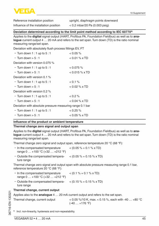
Reference installation position upright, diaphragm points downwardInfluenceoftheinstallationposition < 0.2 mbar/20 Pa (0.003 psig)
Deviation determined according to the limit point method according to IEC 607708)
Applies to the digitalsignaloutput(HART,ProfibusPA,FoundationFieldbus)aswellastoana-logue current output 4 … 20 mA and refers to the set span. Turn down (TD) is the ratio nominal measuring range/set span.DeviationwithabsolutelyflushprocessfittingsEV,FT
Ʋ Turn down 1 : 1 up to 5 : 1 < 0.05 % Ʋ Turn down > 5 : 1 < 0.01 % x TD
Deviation with version 0.075 % Ʋ Turn down 1 : 1 up to 5 : 1 < 0.075 % Ʋ Turn down > 5 : 1 < 0.015 % x TD
Deviation with version 0.1 % Ʋ Turn down 1 : 1 up to 5 : 1 < 0.1 % Ʋ Turn down > 5 : 1 < 0.02 % x TD
Deviation with version 0.2 % Ʋ Turn down 1 : 1 up to 5 : 1 < 0.2 % Ʋ Turn down > 5 : 1 < 0.04 % x TD
Deviation with absolute pressure measuring range 0.1 bar Ʋ Turn down 1 : 1 up to 5 : 1 < 0.25 % Ʋ Turn down > 5 : 1 < 0.05 % x TD
InfluenceoftheproductorambienttemperatureThermal change zero signal and output spanApplies to the digitalsignaloutput(HART,ProfibusPA,FoundationFieldbus)aswellastoana-logue current output 4 … 20 mA and refers to the set span. Turn down (TD) is the ratio nominal measuring range/set span.Thermalchangezerosignalandoutputspan,referencetemperature20°C(68°F):
Ʋ In the compensated temperature range 0 … +100 °C (+32 … +212 °F)
< (0.05 % + 0.1 % x TD)
Ʋ Outside the compensated tempera-ture range
< (0.05 % + 0.15 % x TD)
Thermalchangezerosignalandoutputspanwithabsolutepressuremeasuringrange0.1bar,reference temperature 20 °C (68 °F):
Ʋ In the compensated temperature range 0 … +100 °C (+32 … +212 °F)
< (0.1 % + 0.1 % x TD)
Ʋ Outside the compensated tempera-ture range
< (0.15 % + 0.15 % x TD)
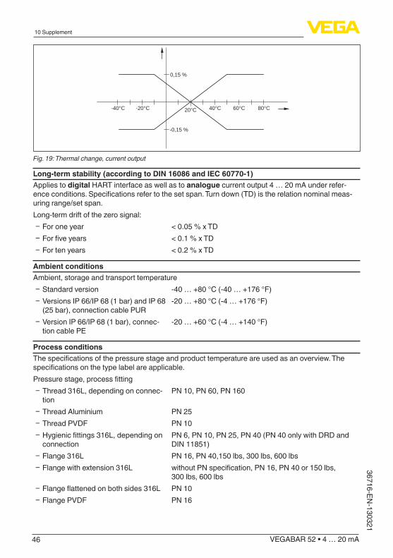
Thermal change, current outputApplies also to the analogue 4 … 20 mA current output and refers to the set span.Thermal change, current output < 0.05 %/10 K, max. < 0.15 %, each with -40 … +80 °C
(-40 … +176 °F)
8) Incl. non-linearity, hysteresis and non-repeatability.
46
10 Supplement
VEGABAR 52 • 4 … 20 mA
36716-EN-130321
0,15 %
-0,15 %
-40°C -20°C 20°C 40°C 60°C 80°C
Fig. 19: Thermal change, current output
Long-termstability(accordingtoDIN16086andIEC60770-1)Applies to digital HART interface as well as to analogue current output 4 … 20 mA under refer-enceconditions.Specificationsrefertothesetspan.Turndown(TD)istherelationnominalmeas-uring range/set span.Long-termdriftofthezerosignal:
Ʋ For one year < 0.05 % x TD Ʋ Forfiveyears < 0.1 % x TD Ʋ For ten years < 0.2 % x TD
Ambient conditionsAmbient, storage and transport temperature
Ʋ Standard version -40 … +80 °C (-40 … +176 °F) Ʋ Versions IP 66/IP 68 (1 bar) and IP 68 (25bar),connectioncablePUR
-20 … +80 °C (-4 … +176 °F)
Ʋ Version IP 66/IP 68 (1 bar), connec-tion cable PE
-20 … +60 °C (-4 … +140 °F)
Process conditionsThespecificationsofthepressurestageandproducttemperatureareusedasanoverview.Thespecificationsonthetypelabelareapplicable.Pressurestage,processfitting
Ʋ Thread 316L, depending on connec-tion
PN 10, PN 60, PN 160
Ʋ Thread Aluminium PN 25 Ʋ Thread PVDF PN 10 Ʋ Hygienicfittings316L,dependingonconnection
PN 6, PN 10, PN 25, PN 40 (PN 40 only with DRD and DIN 11851)
Ʋ Flange 316L PN 16, PN 40,150 lbs, 300 lbs, 600 lbs Ʋ Flange with extension 316L withoutPNspecification,PN16,PN40or150lbs,
300 lbs, 600 lbs Ʋ Flangeflattenedonbothsides316L PN 10 Ʋ Flange PVDF PN 16
47
10 Supplement
VEGABAR 52 • 4 … 20 mA
3671
6-EN
-130
321
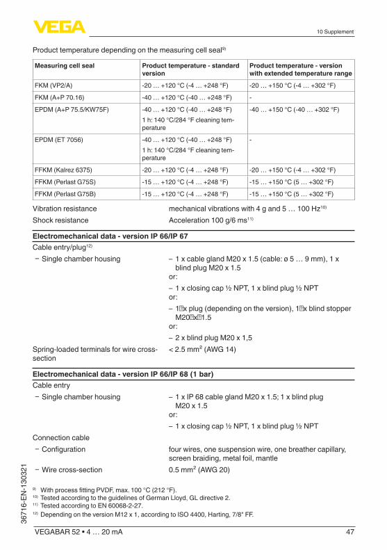
Product temperature depending on the measuring cell seal9)
Measuring cell seal Product temperature - standard version
Product temperature - version with extended temperature range
FKM (VP2/A) -20 … +120 °C (-4 … +248 °F) -20 … +150 °C (-4 … +302 °F)
FKM (A+P 70.16) -40 … +120 °C (-40 … +248 °F) -
EPDM (A+P 75.5/KW75F) -40 … +120 °C (-40 … +248 °F)1 h: 140 °C/284 °F cleaning tem-perature
-40 … +150 °C (-40 … +302 °F)
EPDM (ET 7056) -40 … +120 °C (-40 … +248 °F)1 h: 140 °C/284 °F cleaning tem-perature
-
FFKM(Kalrez6375) -20 … +120 °C (-4 … +248 °F) -20 … +150 °C (-4 … +302 °F)
FFKM (Perlast G75S) -15 … +120 °C (-4 … +248 °F) -15 … +150 °C (5 … +302 °F)
FFKM (Perlast G75B) -15 … +120 °C (-4 … +248 °F) -15 … +150 °C (5 … +302 °F)
Vibration resistance mechanicalvibrationswith4gand5…100Hz10)
Shock resistance Acceleration 100 g/6 ms11)
Electromechanical data - version IP 66/IP 67Cable entry/plug12)
Ʋ Single chamber housing – 1 x cable gland M20 x 1.5 (cable: ø 5 … 9 mm), 1 x blind plug M20 x 1.5
or: – 1 x closing cap ½ NPT, 1 x blind plug ½ NPT
or: – 1␣xplug(dependingontheversion),1␣xblindstopperM20␣x␣1.5
or: – 2 x blind plug M20 x 1,5
Spring-loaded terminals for wire cross-section
< 2.5 mm² (AWG 14)
Electromechanicaldata-versionIP66/IP68(1bar)Cable entry
Ʋ Single chamber housing – 1 x IP 68 cable gland M20 x 1.5; 1 x blind plug M20 x 1.5
or: – 1 x closing cap ½ NPT, 1 x blind plug ½ NPT
Connection cable Ʋ Configuration four wires, one suspension wire, one breather capillary,
screen braiding, metal foil, mantle Ʋ Wire cross-section 0.5 mm² (AWG 20)
9) WithprocessfittingPVDF,max.100°C(212°F).10) Tested according to the guidelines of German Lloyd, GL directive 2.11) Tested according to EN 60068-2-27.12)Depending on the version M12 x 1, according to ISO 4400, Harting, 7/8" FF.

48
10 Supplement
VEGABAR 52 • 4 … 20 mA
36716-EN-130321
Ʋ Wire resistance <0.036Ω/m(0.011Ω/ft) Ʋ Tensile strength > 1200 N (270 pounds force) Ʋ Standard length 5 m (16.4 ft) Ʋ Max. length 1000 m (3281 ft) Ʋ Min. bending radius at 25 °C/77 °F 25 mm (0.985 in) Ʋ Diameter approx. 8 mm (0.315 in) Ʋ Colour - Non-Ex version Black Ʋ Colour - Ex-version Blue
Electromechanical data - version IP 68Connection cable between IP 68 instrument and external housing:
Ʋ Configuration four wires, one suspension wire, one breather capillary, screen braiding, metal foil, mantle
Ʋ Wire cross-section 0.5 mm² (AWG 20) Ʋ Wire resistance <0.036Ω/m(0.011Ω/ft) Ʋ Standard length 5 m (16.40 ft) Ʋ Max. length 180 m (590.5 ft) Ʋ Min. bending radius at 25 °C/77 °F 25 mm (0.985 in) Ʋ Diameter approx. 8 mm (0.315 in) Ʋ Colour Blue
Cable entry/plug13)
Ʋ External housing – 1 x cable gland M20 x 1.5 (cable: ø 5 … 9 mm), 1 x blind plug M20 x 1.5
or: – 1␣xplug(dependingontheversion),1␣xblindstopperM20␣x␣1.5
Spring-loaded terminals for wire cross-section up to
2.5 mm² (AWG 14)
Display and adjustment moduleVoltage supply and data transmission through the sensorIndication LC display in dot matrixAdjustment elements 4 keysProtection rating
Ʋ unassembled IP 20 Ʋ mounted into the sensor without cover IP 40
Material Ʋ Housing ABS Ʋ Inspection window Polyester foil
Voltage supplyOperating voltage
13)Depending on the version M12 x 1, according to ISO 4400, Harting, 7/8" FF.

49
10 Supplement
VEGABAR 52 • 4 … 20 mA
3671
6-EN
-130
321
Ʋ Non-Ex instrument 12 … 36 V DC Ʋ Ex-ia instrument 12 … 30 V DC Ʋ Exd instrument 18 … 36 V DC
Operating voltage with illuminated display and adjustment module Ʋ Non-Ex instrument 20 … 36 V DC Ʋ Ex-ia instrument 20 … 30 V DC Ʋ Exd instrument 20 … 36 V DC
Permissible residual ripple Ʋ <100Hz Uss < 1 V Ʋ 100Hz…10kHz Uss < 10 mV
Load see diagram
1000
750
500
250
12 181614 20 22 24 26 28 30 32 34 36 V
3
12
Fig. 20: Voltage diagram1 Voltage limit Ex-ia instrument2 Voltage limit non-Ex/Ex-d instrument3 Operating voltage
Electrical protective measuresProtection rating
Ʋ Housing, standard IP 66/IP 6714)
Ʋ Aluminium and stainless housing (optionally available)
IP 68 (1 bar)15)
Ʋ Process component in IP 68 version IP 68 (25 bar) Ʋ External housing IP 65, IP 66/IP 68 (0.2 bar)
Overvoltage category IIIProtection class II
Functionalsafety(SIL)FunctionalsafetyisalreadyactivatedoninstrumentswithSILqualificationexfactory.Oninstru-mentswithoutSILqualificationexfactory,thefunctionalsafetymustbeactivatedbytheuserviathe display and adjustment module or via PACTware for applications according to SIL.
14) Instruments with gauge pressure measuring ranges cannot detect the ambient pressure when submerged, e.g. inwater.Thiscanleadtofalsificationofthemeasuredvalue.
15) Only with instruments with absolute pressure ranges.

50
10 Supplement
VEGABAR 52 • 4 … 20 mA
36716-EN-130321
Functional safety according to IEC 61508-4 Ʋ Single channel architecture (1oo1D) up to SIL2 Ʋ double channel diversitary redundant architecture (1oo2D)
up to SIL3
YoucanfinddetailedinformationinthesuppliedSafetyManualoftheinstrumentseriesorunder"www.vega.com","Downloads","Approvals".
ApprovalsInstrumentswithapprovalscanhavedifferenttechnicaldatadependingontheversion.For that reason the associated approval documents of these instruments have to be carefully noted. They are part of the delivery or can be downloaded under www.vega.comvia"VEGA Tools"and"serial number search"aswellasvia"Downloads"and"Approvals".
10.2 DimensionsThe following dimensional drawings represent only an extract of the possible versions. Detailed dimensional drawings can be downloaded on www.vega.comunder"Downloads"and"Drawings".The double chamber housings are only available for Ex-d version with instruments with 4 … 20 mA signal output.
Plastic housing~ 69 mm(2.72")
ø 79 mm(3.03")
112
mm
(4.4
1")
M20x1,5/½ NPT
~ 84 mm (3.31")
M16x1,5
112
mm
(4.4
1")
M20x1,5/½ NPT1 2
ø 79 mm(3.31")
Fig. 21: Housing versions in protection IP 66/IP 68 (0.2 bar) - with integrated display and adjustment module the housing is 9 mm/0.35 in higher1 Single chamber version2 Double chamber version

51
10 Supplement
VEGABAR 52 • 4 … 20 mA
3671
6-EN
-130
321
Aluminium housing
21
ø 86 mm (3.39")~ 116 mm (4.57")
116
mm
(4.5
7")
M20x1,5M20x1,5/½ NPT
~ 87 mm (3.43")
M16x1,5
ø 86 mm(3.39")
120
mm
(4.7
2")
M20x1,5/½ NPT
Fig. 22: Housing versions in protection IP 66/IP 68 (0.2 bar) - with integrated display and adjustment module the housing is 9 mm/0.35 in higher1 Single chamber version2 Double chamber version
AluminiumhousinginprotectionratingIP66/IP68(1bar)
120
mm
(4.7
2")
~ 105 mm (4.13")
116
mm
(4.5
7")
~ 150 mm (5.91")
ø 84 mm (3.31") ø 84 mm(3.31")
M20x1,5/½ NPT
M16x1,5
2
M20x1,5M20x1,5
1
Fig. 23: Housing versions in protection IP␣66/IP␣68 (1␣bar) - with integrated display and adjustment module the housing is 9␣mm/0.35␣in higher1 Single chamber version2 Double chamber version

52
10 Supplement
VEGABAR 52 • 4 … 20 mA
36716-EN-130321
Stainless steel housing~ 69 mm(2.72")
ø 79 mm(3.11")
117
mm
(4.6
1")
M20x1,5/½ NPT
~ 59 mm(2.32")
ø 80 mm(3.15")
112
mm
(4.4
1")
M20x1,5/½ NPT
~ 87 mm (3.43")ø 86 mm(3.39")
120
mm
(4.7
2")
M20x1,5/½ NPT
M16x1,5
321
Fig. 24: Housing versions in protection IP 66/IP 68 (0.2 bar) - with integrated display and adjustment module the housing is 9 mm/0.35 in higher1 Single chamber version, electropolished2 Single chamber version, precision casting3 Double chamber version, precision casting
StainlesssteelhousinginprotectionratingIP66/IP68(1bar)
117
mm
(4.6
1")
~ 103 mm(4.06") ø 77 mm
(3.03")
120
mm
(4.7
2")
~ 105 mm (4.13")ø 84 mm(3.31")
~ 93 mm(3.66") ø 80 mm
(3.15")
112
mm
(4.4
1")
M20x1,5/½ NPT
M20x1,5
3M20x1,5/½ NPT
M16x1,5
21
Fig. 25: Housing versions in protection IP␣66/IP␣68 (1␣bar) - with integrated display and adjustment module the housing is 9␣mm/0.35␣in higher1 Single chamber version, electropolished2 Single chamber version, precision casting2 Double chamber version, precision casting

53
10 Supplement
VEGABAR 52 • 4 … 20 mA
3671
6-EN
-130
321
External housing with version IP 68
1
2
65 mm(2.68")
68 m
m(2
.68"
)92
mm
(3.6
2")
42mm(1.65")
40mm(1.57")
~ 66 mm (2.60")
59 m
m (2
.32"
)
110 mm x 90 mm (4.33" x 3.54")
Fig. 26: IP 68 version with external housing - plastic version1 Lateral cable outlet2 Axial cable outlet
1
2
3
68 mm(2.68")
68 m
m(2
.68"
)92
mm
(3.6
2")
42mm(1.65")
40mm(1.57")
110 mm x 90 mm (4.33" x 3.54")
51 m
m (2
.01"
)
Fig. 27: External housing - Stainless steel version1 Lateral cable outlet2 Axial cable outlet3 Seal 2 mm (0.079 in) - only with 3A approval

54
10 Supplement
VEGABAR 52 • 4 … 20 mA
36716-EN-130321
VEGABAR52,threadedfitting1
GI GM/GN
GV/GC
GB
GSGL/GU
G½A
G¼A
G½A
G¼A
G½A½"NPT
M20x1,5
SW 27 mm(1 1/16")
G½A
23 m
m(2
9 /32
")73
mm
(2 7 /
8")
70 m
m(2
3 /4"
)
17 m
m(4
3 /64
")
85 m
m(3
11/ 3
2")
17 m
m(4
3 /64
")
3 m
m(1
/ 8")
20 m
m(2
5 /32
")
15 m
m(1
9 /32
")
3 m
m(1
/ 8")
20 m
m(2
5 /32
")2
mm
(5/ 6
4")ø 3 mm
(1/8") ø 6 mm (15/64")
25 m
m(6
3 /64
")75
mm
(2 61
/ 64"
)
5 m
m(1
3 /64
") ø 3 mm (1/8") ø 6 mm
(15/64")
25 m
m(6
3 /64
")
73 m
m(2
7 /8"
)
75 m
m(2
61/ 6
4")
ø 3 mm (1/8") ø 6 mm
(15/64")
ø 17,5 mm (11/16") ø 17,5 mm
(11/16")
23 m
m(2
9 /32
")
3 m
m(1
/ 8") ¼"NPT
Fig. 28: VEGABAR 52, threaded fitting: GV/GC = G½ A manometer connection EN 837, GL/GU = G½ A inner G¼ A, GS = G½ A inner G¼ A PVDF, GI = G½ A manometer connection volume-reduced, GM/GN = ½ NPT, GB = M20 x 1.5 manometer connection EN 837
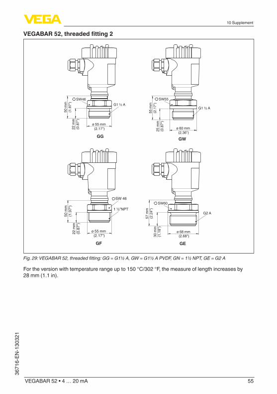
55
10 Supplement
VEGABAR 52 • 4 … 20 mA
3671
6-EN
-130
321
VEGABAR52,threadedfitting2
GF GE
GWGG
SW46 SW55G1 ½ A
G2 A
G1 ½ A
50 m
m(1
.97"
)
55 m
m(2
.17"
)
22 m
m(0
.87"
)
SW60
57 m
m(2
.24"
)30
mm
(1.1
8")
25 m
m(0
.87"
)
ø 55 mm (2.17")
ø 68 mm (2.68")
ø 60 mm (2.36")
SW 46
1 ½”NPT
50 m
m(1
.97"
)22
mm
(0.8
7")
ø 55 mm (2.17")
Fig. 29: VEGABAR 52, threaded fitting: GG = G1½ A, GW = G1½ A PVDF, GN = 1½ NPT, GE = G2 A
For the version with temperature range up to 150 °C/302 °F, the measure of length increases by 28 mm (1.1 in).
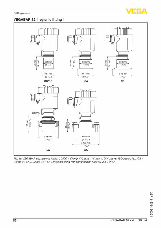
56
10 Supplement
VEGABAR 52 • 4 … 20 mA
36716-EN-130321
VEGABAR52,hygienicfitting1
SW46
51 m
m(2
1 /64
")
51 m
m(2
1 /64
")
51 m
m(2
1 /64
")
60 m
m(2
23/ 6
4")
ø 64 mm(2 33/64")
ø 51 mm(2 1/64")
ø 78 mm(3 5/64")
ø 78 mm(3 5/64")
55 m
m(2
11/ 6
4")
ø 66 mm (2 19/32")
ø 105 mm (4 9/64")
CACD/CC
AA
CE
LA
ø 38mm(1 1/2")
ø 38 mm(1 1/2")
ø 38 mm(1 1/2")
Fig. 30: VEGABAR 52, hygienic fitting: CD/CC = Clamp 1"/Clamp 1½" acc. to DIN 32676, ISO 2852/316L, CA = Clamp 2", CA = Clamp 2½", LA = hygienic fitting with compression nut F40, AA = DRD

57
10 Supplement
VEGABAR 52 • 4 … 20 mA
3671
6-EN
-130
321
VEGABAR52,hygienicfitting2
SW46
50 m
m(1
31/ 3
2")
51 m
m(2
1/ 6
4")
60 m
m(2
23/ 6
4")
51 m
m(2
1 /64
")
51 m
m(2
1 /64
")ø 78 mm (3 5/64")ø 92 mm (3 5/8")
ø 92 mm (3 5/8") ø 74 mm (2 29/32")ø 84 mm (3 5/16")
ø 84 mm(3 5/16")
ø 66 mm(2 19/32")
TA TC RA/RB
RS/RTRD
Fig. 31: VEGABAR 52, hygienic fitting: TA = Tuchenhagen Varivent DN 32, TB = Tuchenhagen Varivent DN 25, RA/RB = bolting DN 40/DN 50 according to DIN 11851, RD = bolting DN 50 according to DIN 11864, RS/RT = SMS DN 38/DN 51

58
10 Supplement
VEGABAR 52 • 4 … 20 mA
36716-EN-130321
VEGABAR52,flangeconnection
3.46"
4.02"
5.43"
0.12"
0.12"
0.12"
4xø 0.71"
4xø 0.71"
8xø 0.71"
4.33"
4.92"
6.30"
5.91"
6.50"
7.87"
0.71"
0.79"
0.95"
5” 0.13"8xø 0.75"6"0.94"7.5"
DNmm PN D kb
EA 40 40 150 18 110FB 50 40 165 20 125
d2
4xø184xø18
d4
88102
f
33
FEFHFI
80 40 200 24 160 8xø18 138 3
3” 2”
1
2 91,9 3,24xø19,1120,719,1152,4190,5 23,9 152,4 8xø19,1 127 3,2
DNinch PN D kb
EA 40 40FB 50 40
d2 d4 f
FEFHFI
80 40
1
2 3.62" 0.13"4xø 0.75"4.75"0.75"6"3”2” 150 lbs
150 lbs
150 lbs150 lbs
d4
k
d2
D
fb50
mm
(1.9
7")
Fig. 32: VEGABAR 52, flange connection1 Flange connection according to DIN 25012 Flange fitting according to ANSI B16.5
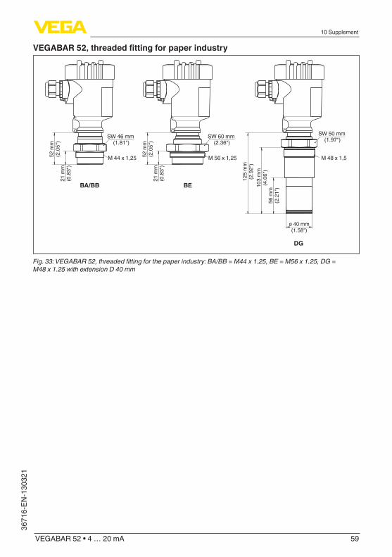
59
10 Supplement
VEGABAR 52 • 4 … 20 mA
3671
6-EN
-130
321
VEGABAR52,threadedfittingforpaperindustry
M 44 x 1,25
SW 46 mm (1.81")
M 56 x 1,25 M 48 x 1,5
SW 60 mm (2.36")
SW 50 mm (1.97")
DG
BA/BB BE
21 m
m(0
.83"
)
52 m
m(2
.05"
)
21 m
m(0
.83"
)
52 m
m(2
.05"
)
56 m
m(2
.21"
)103
mm
(4.0
6")
125
mm
(2.9
2")
ø 40 mm(1.58")
Fig. 33: VEGABAR 52, threaded fitting for the paper industry: BA/BB = M44 x 1.25, BE = M56 x 1.25, DG = M48 x 1.25 with extension D 40 mm

60
10 Supplement
VEGABAR 52 • 4 … 20 mA
36716-EN-130321
VEGABAR52,flangeconnectionforpaperindustry1
FG
TR
TS
EW158
mm
(6.2
2")
40 m
m(1
.58"
)
ø 38 mm(1.50")
ø 59 mm(2.32")
ø 48 mm(1.89")
ø 32...60 mm(1.26...2.36")
ø 48...90 mm(1.89...3.54")
52 m
m(2
.05"
)24
mm
(0.9
5")
30...
300
mm
(1.1
8...1
1.81
")40
mm
(1.5
8")
25...
300
mm
(0.9
8...1
1.81
")40
mm
(1.5
8")
Fig. 34: VEGABAR 52, flange connection for the paper industry: TR = flange DN 50 with selectable tube, TS = flange DN 80 with selectable tube, FG = flange tube for ball valve fitting, EW = flange for manometer lug

61
10 Supplement
VEGABAR 52 • 4 … 20 mA
3671
6-EN
-130
321
VEGABAR52,flangeconnectionforpaperindustry2
43 m
m(1
.69"
)
ø 48 mm(1.89")23
mm
(0.9
1")
43 m
m(1
.69"
)
ø 48 mm(1.89")23
mm
(0.9
1")
50 mm(1.97")
50 mm(1.97")
115 mm(4.53")
115
mm
(4.5
3")
68 m
m(2
.68"
)68
mm
(2.6
8")
FT
EV
Fig. 35: VEGABAR 52, flange connection for the paper industry: FT = absolutely front-flush for headbox, EV = absolutely front-flush for headbox (flange 2-times flattened)
62
10 Supplement
VEGABAR 52 • 4 … 20 mA
36716-EN-130321
10.3 Industrial property rightsVEGA product lines are global protected by industrial property rights. Further information see www.vega.com.Only in U.S.A.: Further information see patent label at the sensor housing.VEGA Produktfamilien sind weltweit geschützt durch gewerbliche Schutzrechte.Nähere Informationen unter www.vega.com.Les lignes de produits VEGA sont globalement protégées par des droits de propriété intellec-tuelle. Pour plus d'informations, on pourra se référer au site www.vega.com.VEGA lineas de productos están protegidas por los derechos en el campo de la propiedad indus-trial. Para mayor información revise la pagina web www.vega.com.Линии продукции фирмы ВЕГА защищаются по всему миру правами на интеллектуальную собственность. Дальнейшую информацию смотрите на сайте www.vega.com.VEGA系列产品在全球享有知识产权保护。进一步信息请参见网站<www.vega.com>。
10.4 TrademarkAll the brands as well as trade and company names used are property of their lawful proprietor/originator.

63
INDEX
VEGABAR 52 • 4 … 20 mA
3671
6-EN
-130
321
INDEX
AAccessories
– Display and adjustment module 10 – Flanges 10 – Measuring instrument holder 10 – Protective cover 10
Application area 8
CCable entry 15Cable screening 16Check output signal 35Connection cable 15Connection VEGACONNECT
– directly on the sensor 34Copy sensor data 29
DDisposal 40
EElectronics and connection compartment 18Error messages 36
FFaultrectification35
HHotline 35
IInstallation position 11
LLinearizationcurve29
MMaintenance 35Max. adjustment 26Min. adjustment 25Moisture 11Mounting external housing 13
PPosition correction 25, 28Pressure compensation 11Process conditions 11
RRecycling 40
Repair form 39Replacement parts
– Electronics module 10Reset 30Return form 39
SSafety data sheet 39Seal concept 9Service hotline 35Span adjustment 29
TTemperature limits 12Total deviation 36Type plate 7
UUnitofmeasurement24,27
VVoltage supply 9, 15
WWEEE directive 40Wiring plan 18, 20
ZZero adjustment 28

Printing date:
VEGA Grieshaber KGAm Hohenstein 11377761 SchiltachGermany
3671
6-E
N-1
3032
1All statements concerning scope of delivery, application, practical use and operat-ing conditions of the sensors and processing systems correspond to the information available at the time of printing.Subject to change without prior notice
© VEGA Grieshaber KG, Schiltach/Germany 2013
Phone +49 7836 50-0Fax +49 7836 50-201E-mail: [email protected]