operating instructions process pressure …...wika operating instructions - process pressure...
TRANSCRIPT

Operating Instructions
Process pressure transmitter IPT-1*
Process pressure transmitter IPT-1*
4 … 20 mA/HARTmetallic sensorVersion 3.0

2
Contents
WIKA Operating Instructions - Process pressure transmitter IPT-1*
Contents1 About this document
1.1 Function ........................................................................................................................... 41.2 Target group ..................................................................................................................... 41.3 Symbolism used ............................................................................................................... 4
2 For your safety2.1 Authorised personnel ....................................................................................................... 52.2 Appropriate use ................................................................................................................ 52.3 Warning about incorrect use ............................................................................................. 52.4 General safety instructions ............................................................................................... 52.5 Safety label on the instrument .......................................................................................... 52.6 CE conformity ................................................................................................................... 62.7 Measuring range - permissible process pressure ............................................................. 62.8 FulfillmentofNAMURrecommendations ......................................................................... 62.9 Safety instructions for Ex areas ........................................................................................ 62.10 Safety instructions for oxygen applications ....................................................................... 6
3 Product description3.1 Configuration .................................................................................................................... 73.2 Principle of operation........................................................................................................ 83.3 Adjustment ....................................................................................................................... 83.4 Packaging, transport and storage ..................................................................................... 8
4 Mounting4.1 General instructions ....................................................................................................... 104.2 Mounting instructions ..................................................................................................... 124.3 Mounting steps ............................................................................................................... 12
5 Connecting to power supply5.1 Preparing the connection ............................................................................................... 135.2 Connection procedure .................................................................................................... 145.3 Wiring plan, single chamber housing.............................................................................. 155.4 Wiring plan, double chamber housing ............................................................................ 175.5 Wiring plan, double chamber housing Ex d .................................................................... 195.6 Wiring plan, external housing with version IP 68 (25 bar) ............................................... 215.7 Switch-on phase............................................................................................................. 22
6 Set up with the display and adjustment module6.1 Short description ............................................................................................................ 246.2 Insert display and adjustment module ............................................................................ 246.3 Adjustment system ......................................................................................................... 256.4 Setup steps .................................................................................................................... 266.5 Menu schematic ............................................................................................................. 346.10 Saving the parameter adjustment data ........................................................................... 36
7 Set up with PACTware and other adjustment programs7.1 Connect the PC .............................................................................................................. 377.2 Parameter adjustment with PACTware ............................................................................ 377.3 Parameter adjustment with AMS™ and PDM ................................................................. 387.4 Saving the parameter adjustment data ........................................................................... 38
8 Maintenanceandfaultrectification

3
Contents
WIKA Operating Instructions - Process pressure transmitter IPT-1*
8.1 Maintenance .................................................................................................................. 398.2 Rectify faults ................................................................................................................... 398.3 Instrument repair ............................................................................................................ 40
9 Dismounting9.1 Dismounting steps.......................................................................................................... 419.2 Disposal ......................................................................................................................... 41
10 Supplement10.1 Technical data ................................................................................................................ 4210.2 Dimensions .................................................................................................................... 49
Supplementary documentationInformation:Supplementary documents appropriate to the ordered version come withthedelivery.Youcanfindthemlistedinchapter"Product descrip-tion".
Instructions manuals for accessories and replacement partsTip:ToensurereliablesetupandoperationofyourIPT-1*,weofferacces-sories and replacement parts. The corresponding documentations are:
• Operatinginstructionsmanual"External display and adjustment unit"
Editing status: 2013-06-05

4
1 About this document
WIKA Operating Instructions - Process pressure transmitter IPT-1*
1 About this document
1.1 FunctionThis operating instructions manual provides all the information you need for mounting, connection and setup as well as important instruc-tionsformaintenanceandfaultrectification.Pleasereadthisinforma-tion before putting the instrument into operation and keep this manual accessible in the immediate vicinity of the device.
1.2 Target groupThis operating instructions manual is directed to trained specialist personnel. The contents of this manual should be made available to these personnel and put into practice by them.
1.3 Symbolism usedInformation, tip, noteThis symbol indicates helpful additional information.Caution: If this warning is ignored, faults or malfunctions can result.Warning: If this warning is ignored, injury to persons and/or serious damage to the instrument can result.Danger: If this warning is ignored, serious injury to persons and/or destruction of the instrument can result.
Ex applicationsThis symbol indicates special instructions for Ex applications.
• ListThe dot set in front indicates a list with no implied sequence.
→ ActionThis arrow indicates a single action.
1 Sequence of actionsNumberssetinfrontindicatesuccessivestepsinaprocedure.
Battery disposalThis symbol indicates special information about the disposal of bat-teries and accumulators.

5
2 For your safety
WIKA Operating Instructions - Process pressure transmitter IPT-1*
2 For your safety
2.1 Authorised personnelMount and set up the pressure transmitter only if you know the appli-cablenationalregulationsandhavetheappropriatequalification.Youmust be aquainted with the regulations and instructions for hazard-ous areas, measurement and control technology as well as electrical circuitsbecausethepressuretransmitteris"electricalequipment"accordingtoEN50178.Dependingontheapplicationconditions,itis necessary that you have appropriate knowledge, e.g. concerning corrosive products or high pressure.
2.2 Appropriate useIPT-1* is a pressure transmitter for measurement of gauge pressure, absolute pressure and vacuum. Youcanfinddetailedinformationontheapplicationrangeinchapter"Product description".Operational reliability is ensured only if the instrument is properly usedaccordingtothespecificationsintheoperatinginstructionsmanual as well as possible supplementary instructions.For safety and warranty reasons, any invasive work on the device beyond that described in the operating instructions manual may be carried out only by personnel authorised by the manufacturer. Arbi-traryconversionsormodificationsareexplicitlyforbidden.
2.3 Warning about incorrect useInappropriate or incorrect use of the instrument can give rise to application-specifichazards,e.g.vesseloverfillordamagetosystemcomponents through incorrect mounting or adjustment.
2.4 General safety instructionsThis is a high-tech instrument requiring the strict observance of stand-ard regulations and guidelines. The user must take note of the safety instructionsinthisoperatinginstructionsmanual,thecountry-specificinstallation standards as well as all prevailing safety regulations and accident prevention rules.Theinstrumentmustonlybeoperatedinatechnicallyflawlessandreliable condition. The operator is responsible for trouble-free opera-tion of the instrument.During the entire duration of use, the user is obliged to determine the compliance of the necessary occupational safety measures with the current valid rules and regulations and also take note of new regula-tions.
2.5 Safety label on the instrumentThe safety approval markings and safety tips on the device must be observed.

6
2 For your safety
WIKA Operating Instructions - Process pressure transmitter IPT-1*
2.6 CE conformityThisdevicefulfillsthelegalrequirementsoftheapplicableECguide-lines.ByattachingtheCEmark,weprovideconfirmationofsuccess-ful testing.
2.7 Measuring range - permissible process pressure
Due to the application, a measuring cell with a measuring range higherthanthepermissiblepressurerangeoftheprocessfittingmayhave been integrated. The permissible process pressure is stated with "Processpressure"onthetypelabel,seechapter3.1"Configuration".For safety reasons, this range must not be exceeded.
2.8 FulfillmentofNAMURrecommendationsThedevicefulfillstherequirementsoftheapplicableNAMURrecom-mendations.
2.9 Safety instructions for Ex areasPleasenotetheEx-specificsafetyinformationforinstallationandop-eration in Ex areas. These safety instructions are part of the operating instructions manual and come with the Ex-approved instruments.
2.10 Safety instructions for oxygen applicationsFor instruments in oxygen applications the special instructions in chapters"Storage and transport","Mounting"aswellas"Technical data"under"Process conditions"mustbenoted.Furthermorethevalidnational regulations, implementation instructions and memorandums of the professional assocations must be noted.

7
3 Product description
WIKA Operating Instructions - Process pressure transmitter IPT-1*
3 Product description
3.1 ConfigurationThe scope of delivery encompasses:
• IPT-1* process pressure transmitter• Documentation
– this operating instructions manual – Testcertificateforpressuretransmitters – SafetyManual"IPT-1* - 4 … 20 mA/HART two-wire"(optional) – Operatinginstructionsmanual"Display and adjustment mod-
ule"(optional) – Supplementaryinstructionsmanual"Plug connector for con-
tinuously measuring sensors"(optional) – Ex-specific"Safety instructions"(withExversions) – ifnecessary,furthercertificates
Instrumentsintheversion"Oil and grease-free for oxygen applica-tions"areequippedwithasupplementarylabel.Thesupplementarylabel contains instructions on oil and grease-free parts of the instru-ment.
The IPT-1* consists of the components:
• Processfittingwithmeasuringcell• Housing with electronics, optionally available with plug connector• Housing cover, optionally available with display and adjustment
module
Thecomponentsareavailableindifferentversions.
1
2
3
Fig. 1: Example of a IPT-1* with manometer connection G½ according to EN 837 and Alu housing1 Housing cover with integrated display and adjustment module (optional)2 Housing with electronics3 Process fitting with measuring cell
Thenameplatecontainsthemostimportantdataforidentificationanduse of the instrument:
• Instrument type• Article and serial number device
Scope of delivery
Supplementary label "Oil and grease-free for oxygen applications"
Constituent parts
Type plate

8
3 Product description
WIKA Operating Instructions - Process pressure transmitter IPT-1*
• Technical data: Measuring range, process pressure, process tem-perature, signal output, voltage supply, protection, protection class
• Order number• Article number, documentation• SILidentification(withSILratingexworks)
3.2 Principle of operationIPT-1* is a pressure transmitter for measurement of overpressure, absolute pressure or vacuum. Measured products are gases, vapours and liquids in measuring ranges up to 4000 bar (400 MPa); with front-flushversionalsoviscousliquidsinmeasuringrangesupto600bar(60 MPa).
The process pressure acts on the sensor element via the stainless steel diaphragm and an internal transmission liquid. This causes a resistance change which is converted into a corresponding output signal and outputted as a measured value. With measuring ranges up to 16 bar a pieoresistive sensor element is used, with measuring ranges from 25 bar a strain gauge (DMS) sensor element.
4 … 20 mA/HART two-wire electronics for voltage supply and meas-ured value transmission on the same cable.Thesupplyvoltagerangecandifferdependingontheinstrumentver-sion.Theexactrangeisstatedinchapter"Technical data".The backlight of the display and adjustment module is powered by the sensor. The prerequisite for this is a supply voltage at a certain level.Theexactvoltagespecificationsarestatedinchapter"Technical data".
3.3 AdjustmentThe instrument can be adjusted with the following adjustment media:
• With the display and adjustment module• the suitable WIKA DTM in conjunction with an adjustment software
according to the FDT/DTM standard, e.g. PACTware and PC• withmanufacturer-specificadjustmentprogramsAMS™orPDM• With a HART handheld
The entered parameters are generally saved in IPT-1*, optionally also in the display and adjustment module or in PACTware.
3.4 Packaging, transport and storageYour instrument was protected by packaging during transport. Its capacity to handle normal loads during transport is assured by a test based on ISO 4180.The packaging of standard instruments consists of environment-friendly, recyclable cardboard. For special versions, PE foam or PE foil is also used. Dispose of the packaging material via specialised recycling companies.
Application area
Functional principle
Voltage supply
Packaging

9
3 Product description
WIKA Operating Instructions - Process pressure transmitter IPT-1*
Caution:Instruments for oxygen applications are sealed in PE foil and provided withalabel"Oxygen!UsenoOil".Removethisfoiljustbeforemount-ingtheinstrument!Seeinstructionunder"Mounting".
Transport must be carried out under consideration of the notes on the transportpackaging.Nonobservanceoftheseinstructionscancausedamage to the device.
The delivery must be checked for completeness and possible transit damage immediately at receipt. Ascertained transit damage or con-cealed defects must be appropriately dealt with.
Uptothetimeofinstallation,thepackagesmustbeleftclosedandstored according to the orientation and storage markings on the outside.Unlessotherwiseindicated,thepackagesmustbestoredonlyunderthe following conditions:
• Notintheopen• Dry and dust free• Notexposedtocorrosivemedia• Protected against solar radiation• Avoiding mechanical shock and vibration
• Storageandtransporttemperatureseechapter"Supplement - Technical data - Ambient conditions"
• Relative humidity 20 … 85 %
Transport
Transport inspection
Storage
Storage and transport temperature
10
4 Mounting
WIKA Operating Instructions - Process pressure transmitter IPT-1*
4 Mounting
4.1 General instructionsMake sure that all parts of the instrument coming in direct contact with the process, especially the sensor element, process seal and processfitting,aresuitablefortheexistingprocessconditions,suchas process pressure, process temperature as well as the chemical properties of the medium.Youcanfindthespecificationsinchapter"Technical data"andonthenameplate.
Toprotectthediaphragm,theprocessfittingiscoveredbyaprotec-tive cap.Remove the protective cap just before installation so that the dia-phragm will not get damaged. It is recommended to keep the cap and use it again later for storage or transport.
Select an installation position you can easily reach for mounting and connectingaswellaslaterretrofittingofadisplayandadjustmentmodule. The housing can be rotated by 330° without the use of any tools. You can also install the display and adjustment module in four differentpositions(eachdisplacedby90°).
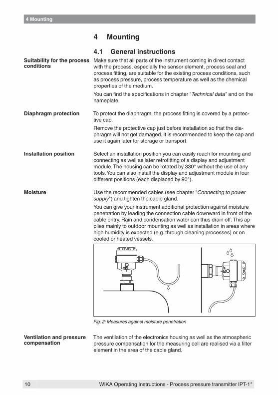
Usetherecommendedcables(seechapter"Connecting to power supply")andtightenthecablegland.You can give your instrument additional protection against moisture penetration by leading the connection cable downward in front of the cableentry.Rainandcondensationwatercanthusdrainoff.Thisap-plies mainly to outdoor mounting as well as installation in areas where high humidity is expected (e.g. through cleaning processes) or on cooled or heated vessels.
Fig. 2: Measures against moisture penetration
The ventilation of the electronics housing as well as the atmospheric pressurecompensationforthemeasuringcellarerealisedviaafilterelement in the area of the cable gland.
Suitability for the process conditions
Diaphragm protection
Installation position
Moisture
Ventilation and pressure compensation
11
4 Mounting
WIKA Operating Instructions - Process pressure transmitter IPT-1*
2
1
1
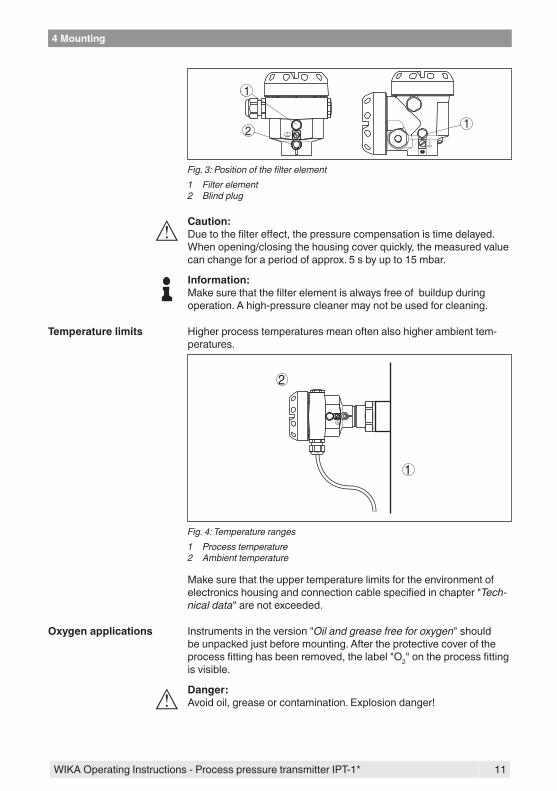
Fig. 3: Position of the filter element1 Filter element2 Blind plug
Caution:Duetothefiltereffect,thepressurecompensationistimedelayed.When opening/closing the housing cover quickly, the measured value can change for a period of approx. 5 s by up to 15 mbar.
Information:Makesurethatthefilterelementisalwaysfreeofbuildupduringoperation. A high-pressure cleaner may not be used for cleaning.
Higher process temperatures mean often also higher ambient tem-peratures.
1
2
Fig. 4: Temperature ranges1 Process temperature2 Ambient temperature
Make sure that the upper temperature limits for the environment of electronicshousingandconnectioncablespecifiedinchapter"Tech-nical data"arenotexceeded.
Instrumentsintheversion"Oil and grease free for oxygen"shouldbe unpacked just before mounting. After the protective cover of the processfittinghasbeenremoved,thelabel"O2"ontheprocessfittingis visible.
Danger:Avoidoil,greaseorcontamination.Explosiondanger!
Temperature limits
Oxygen applications

12
4 Mounting
WIKA Operating Instructions - Process pressure transmitter IPT-1*
4.2 Mounting instructionsIPT-1* functions in any installation position. It is mounted according to thesamedirectivesasamanometer(DINEN839-2).1)
Information:Werecommendusinglockfittings,measuringinstrumentholdersandsiphons from the line of WIKA accessories.
4.3 Mounting stepsTomountIPT-1*,aweldedsocketisnecessary.Usecomponentsfromthe line of WIKA mounting accessories.
→ Notetheapplicableweldingstandards(segmentweldingproce-dure) when welding the socket.
Usethesealcorrespondingtotheinstrument:
• ProcessfittingGD:Tesnitsealinfrontofthethread- or -Seal the thread with resistant seal material:
• ProcessfittingGN→ Screw IPT-1* into the welded socket. Tighten the hexagon on the
processfittingwithasuitablewrench.Wrenchsize,seechapter"Dimensionaldrawings".
Warning:Thehousingmustnotbeusedtoscrewtheinstrumentin!Applyingtightening force can damage internal parts of the housing.
Usethesealsuitablefortherespectiveprocessfitting.Youcanfindthecomponentsinthesupplementaryinstructionsmanual"Welded socket and seals".
Installation position
Welding the socket
Sealing/Screwing in
Sealing/Screwing in hygienicfittings
1) Probablepositioncorrectionseechapter"Setupsteps".

13
5 Connecting to power supply
WIKA Operating Instructions - Process pressure transmitter IPT-1*
5 Connecting to power supply
5.1 Preparing the connectionAlways keep in mind the following safety instructions:
• Connect only in the complete absence of line voltage• If overvoltage surges are expected, overvoltage arresters should
be installed
In hazardous areas you must take note of the respective regulations, conformityandtypeapprovalcertificatesofthesensorsandpowersupply units.
Power supply and current signal are transmitted via the same two-wireconnectioncable.Thesupplyvoltagerangecandifferdependingontheinstrumentversion.Theexactrangeisstatedinthe"Technical data"inthe"Supplement".Provide a reliable separation between the supply circuit and the mainscircuitsaccordingtoDINEN61140VDE0140-1.Keepinmindthefollowingadditionalfactorsthatinfluencetheoperat-ing voltage:
• Output voltage of the power supply unit can be lower under nomi-nal load (with a sensor current of 20.5 mA or 22 mA in case of fault message)
• Influenceofadditionalinstrumentsinthecircuit(seeloadvaluesinchapter"Technical data")
The instrument is connected with standard two-wire cable without screen. If electromagnetic interference is expected which is above the testvaluesofEN61326forindustrialareas,screenedcableshouldbe used.Usecablewithroundcross-section.Acableouterdiameterof5…9mm(0.2…0.35in)ensuresthesealeffectofthecablegland.Ifyouareusingcablewithadifferentdiameterorcross-section,exchange the seal or use a suitable cable gland.
If screened cable is necessary, connect the cable screen on both ends to ground potential. In the sensor, the screen must be connected directly to the internal ground terminal. The ground terminal on the outside of the housing must be connected to the potential equalisa-tion (low impedance).If potential equalisation currents are expected, the connection on the processing side must be made via a ceramic capacitor (e. g. 1 nF, 1500 V). The low-frequency potential equalisation currents are thus suppressed,buttheprotectiveeffectagainsthighfrequencyinterfer-ence signals remains.
Warning:Considerablepotentialdifferencesexistinsidegalvanicplantsaswellas vessels with cathodic corrosion protection. Very large equalisa-tioncurrentscanflowthroughthecablescreenwhenthescreenis grounded on both ends. To avoid this, the cable screen must be
Notesafetyinstructions
Take note of safety instructions for Ex applications
Select power supply
Select connection cable
Cable screening and grounding

14
5 Connecting to power supply
WIKA Operating Instructions - Process pressure transmitter IPT-1*
connected to ground potential only on one end (inside the switch-ing cabinet) in such applications. The cable screen must not be connected to the internal ground terminal in the sensor and the outer ground terminal on the housing nottopotentialequalisation!
Information:The metallic parts of the instrument such as transmitter and process fittingareconductivelyconnectedwiththeinnerandoutergroundterminal on the housing. This connection exists either as a direct me-tallic contact or via the shielding of the special connection cable on instrumentswithexternalelectronics.Youcanfindspecificationsonthepotentialconnectionswithintheinstrumentinchapter"Technical data".Take note of the corresponding installation regulations for Ex applica-tions. In particular, make sure that no potential equalisation currents flowoverthecablescreen.Incaseofgroundingonbothsidesthiscan be achieved by the use of a capacitor or a separate potential equalisation.
5.2 Connection procedureProceed as follows:1. Unscrewthehousingcover2. If a display and adjustment module is installed, remove it by turn-
ing it slightly to the left.3. Loosen compression nut of the cable entry4. Remove approx. 10 cm (4 in) of the cable mantle, strip approx.
1 cm (0.4 in) of insulation from the ends of the individual wires5. Insert the cable into the sensor through the cable entry6. Lift the opening levers of the terminals with a screwdriver (see
following illustration)7. Insert the wire ends into the open terminals according to the wir-
ing plan
Select connection cable for Ex applica-tions

15
5 Connecting to power supply
WIKA Operating Instructions - Process pressure transmitter IPT-1*
Fig. 5: Connection steps 6 and 7
8. Press down the opening levers of the terminals, you will hear the terminal spring closing
9. Check the hold of the wires in the terminals by lightly pulling on them
10. Connect the screen to the internal ground terminal, connect the outer ground terminal to potential equalisation
11. Tighten the compression nut of the cable entry. The seal ring must completely encircle the cable
12. Screw the housing cover back onTheelectricalconnectionishencefinished.
5.3 Wiring plan, single chamber housingThe following illustrations apply to the non-Ex as well as to the Ex-ia version.

16
5 Connecting to power supply
WIKA Operating Instructions - Process pressure transmitter IPT-1*
5 6 7 81 2
Disp
lay
I²C
2
1
4
3
Fig. 6: Electronics and connection compartment, single chamber housing1 Plug connector for service2 Spring-loaded terminals for connection of the external display and adjust-
ment module3 Ground terminal for connection of the cable screen4 Spring-loaded terminals for voltage supply
I2C
Display
1
1 2 5 6 7 8
Fig. 7: Wiring plan, single chamber housing1 Voltage supply, signal output
Electronics and connec-tion compartment
Wiring plan

17
5 Connecting to power supply
WIKA Operating Instructions - Process pressure transmitter IPT-1*
5.4 Wiring plan, double chamber housing
1
3 2
Display
1 2 5 6 7 8
I²C
Fig. 8: Electronics compartment, double chamber housing1 Plug connector for service2 Internal connection cable to the connection compartment3 Terminals for the external display and adjustment unit
1
2
3
Disp
lay
1 2 I2C
Fig. 9: Connection compartment, double chamber housing1 Spring-loaded terminals for voltage supply2 Plug connector for service interface3 Ground terminal for connection of the cable screen
Electronics compartment
Connection compartment

18
5 Connecting to power supply
WIKA Operating Instructions - Process pressure transmitter IPT-1*
I2C
1
1 2
Fig. 10: Wiring plan, double chamber housing1 Voltage supply, signal output
34
1 2
Fig. 11: Top view of the plug connector1 Pin 12 Pin 23 Pin 34 Pin 4
Contact pin Colour connection ca-ble in the sensor
Terminal, electronics module
Pin 1 Brown 5
Pin 2 White 6
Pin 3 Blue 7
Pin 4 Black 8
Wiring plan
Plug M12 x 1 for external display and adjustment unit

19
5 Connecting to power supply
WIKA Operating Instructions - Process pressure transmitter IPT-1*
5.5 Wiring plan, double chamber housing Ex d
1
3 2
Display
1 2 5 6 7 8
I²C
Fig. 12: Electronics compartment, double chamber housing1 Plug connector for service2 Internal connection cable to the connection compartment3 Terminals for the external display and adjustment unit
1
2
1 2
Fig. 13: Connection compartment, Ex-d double chamber housing1 Spring-loaded terminals for power supply and cable screen2 Ground terminal for connection of the cable screen
Electronics compartment
Connection compartment
20
5 Connecting to power supply
WIKA Operating Instructions - Process pressure transmitter IPT-1*
1
1 2
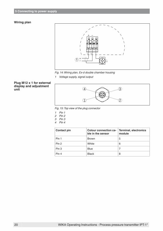
Fig. 14: Wiring plan, Ex-d double chamber housing1 Voltage supply, signal output
34
1 2
Fig. 15: Top view of the plug connector1 Pin 12 Pin 23 Pin 34 Pin 4
Contact pin Colour connection ca-ble in the sensor
Terminal, electronics module
Pin 1 Brown 5
Pin 2 White 6
Pin 3 Blue 7
Pin 4 Black 8
Wiring plan
Plug M12 x 1 for external display and adjustment unit

21
5 Connecting to power supply
WIKA Operating Instructions - Process pressure transmitter IPT-1*
5.6 Wiring plan, external housing with version IP 68 (25 bar)
Fig. 16: IPT-1* in IP 68 version 25 bar and axial cable outlet, external housing
5 6 7 81 2
Disp
lay
I²C
2
1
5
4
3
Fig. 17: Electronics and connection compartment1 Spring-loaded terminals for voltage supply2 Ground terminal for connection of the cable screen3 Cable gland to the process component4 For external display and adjustment unit, Slave sensor5 Plug connector for service interface
Overview
Electronics and connec-tion compartment for power supply

22
5 Connecting to power supply
WIKA Operating Instructions - Process pressure transmitter IPT-1*
1 2 3 4
63
41
2
5
Fig. 18: Connection of the sensor in the housing base1 Brown2 Blue3 Yellow4 White5 Shielding6 Breather capillaries
I2C
Display
1
1 2 5 6 7 8
Fig. 19: Wiring plan external electronics1 Voltage supply
5.7 Switch-on phaseAfter connecting IPT-1* to power supply or after a voltage recurrence, the instrument carries out a self-check for approx. 30 seconds:
• Internal check of the electronics• Indicationoftheinstrumenttype,thefirmwareaswellasthesen-
sor TAGs (sensor designation)• Outputsignaljumpsbriefly(approx.10seconds)tothesetfault
current
Terminal compartment, housing socket
Wiring plan external electronics
Switch-on phase

23
5 Connecting to power supply
WIKA Operating Instructions - Process pressure transmitter IPT-1*
Then the corresponding current is outputted to the cable (the value corresponds to the actual level as well as the settings already carried out, e.g. factory setting).

24
6 Set up with the display and adjustment module
WIKA Operating Instructions - Process pressure transmitter IPT-1*
6 Set up with the display and adjustment module
6.1 Short descriptionThe display and adjustment module is used for measured value display, adjustment and diagnosis. It can be mounted in the following housing versions and instruments:
• All sensors DPT-10 and IPT-1*, in the single as well as double chamber housing (optionally in the electronics or connection compartment)
• External display and adjustment unit
Note:Youcanfinddetailedinformationontheadjustmentintheoperatinginstructionsmanual"Display and adjustment module".
6.2 Insert display and adjustment moduleThe display and adjustment module can be inserted and removed at any time. It is not necessary to interrupt the voltage supply.For installation proceed as follows:1. Unscrewthehousingcover2. Place the display and adjustment module in the desired position
ontheelectronics(youcanchooseanyoneoffourdifferentposi-tions - each displaced by 90°)
3. Press the display and adjustment module onto the electronics and turn it to the right until it snaps in.
4. Screw housing cover with inspection window tightly back onRemoval is carried out in reverse order.The display and adjustment module is powered by the sensor, an ad-ditional connection is not necessary.
Function/Configuration
Mount/Dismount display and adjustment module

25
6 Set up with the display and adjustment module
WIKA Operating Instructions - Process pressure transmitter IPT-1*
Fig. 20: Insert display and adjustment module
Note:Ifyouintendtoretrofittheinstrumentwithadisplayandadjustmentmodule for continuous measured value indication, a higher cover with an inspection glass is required.
6.3 Adjustment system
2
3
1
1.1
Fig. 21: Display and adjustment elements1 LC display2 Indication of the menu item number3 Adjustment keys
26
6 Set up with the display and adjustment module
WIKA Operating Instructions - Process pressure transmitter IPT-1*
• [OK] key: – Move to the menu overview – Confirmselectedmenu – Edit parameter – Save value
• [->] key to select: – Menu change – Select list entry – Select editing position
• [+] key: – Change value of the parameter
• [ESC] key: – Interrupt input – Jump to the next higher menu
The sensor is adjusted via the four keys of the display and adjust-ment module. The LC display indicates the individual menu items. The functions of the individual keys are shown in the above illustration. Approx. 10 minutes after the last pressing of a key, an automatic reset tomeasuredvalueindicationistriggered.Anyvaluesnotconfirmedwith [OK] will not be saved.
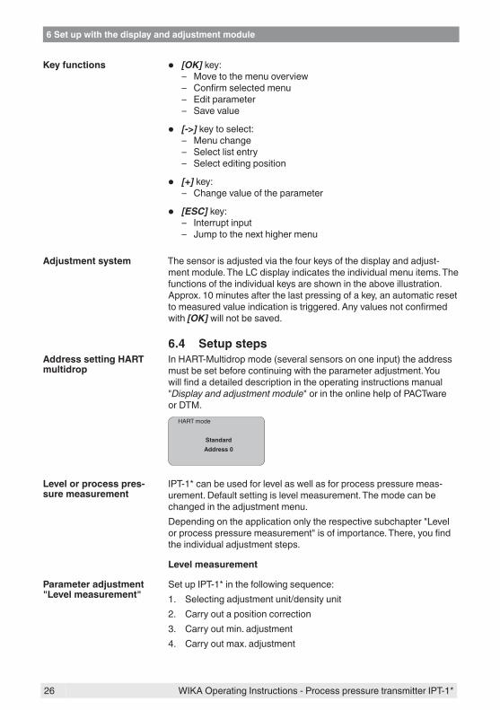
6.4 Setup stepsIn HART-Multidrop mode (several sensors on one input) the address must be set before continuing with the parameter adjustment. You willfindadetaileddescriptionintheoperatinginstructionsmanual"Display and adjustment module"orintheonlinehelpofPACTwareor DTM.
HART mode
StandardAddress 0
IPT-1* can be used for level as well as for process pressure meas-urement. Default setting is level measurement. The mode can be changed in the adjustment menu.Dependingontheapplicationonlytherespectivesubchapter"Levelorprocesspressuremeasurement"isofimportance.There,youfindthe individual adjustment steps.
Level measurement
Set up IPT-1* in the following sequence:1. Selecting adjustment unit/density unit2. Carry out a position correction3. Carry out min. adjustment4. Carry out max. adjustment
Key functions
Adjustment system
AddresssettingHARTmultidrop
Level or process pres-sure measurement
Parameter adjustment "Level measurement"

27
6 Set up with the display and adjustment module
WIKA Operating Instructions - Process pressure transmitter IPT-1*
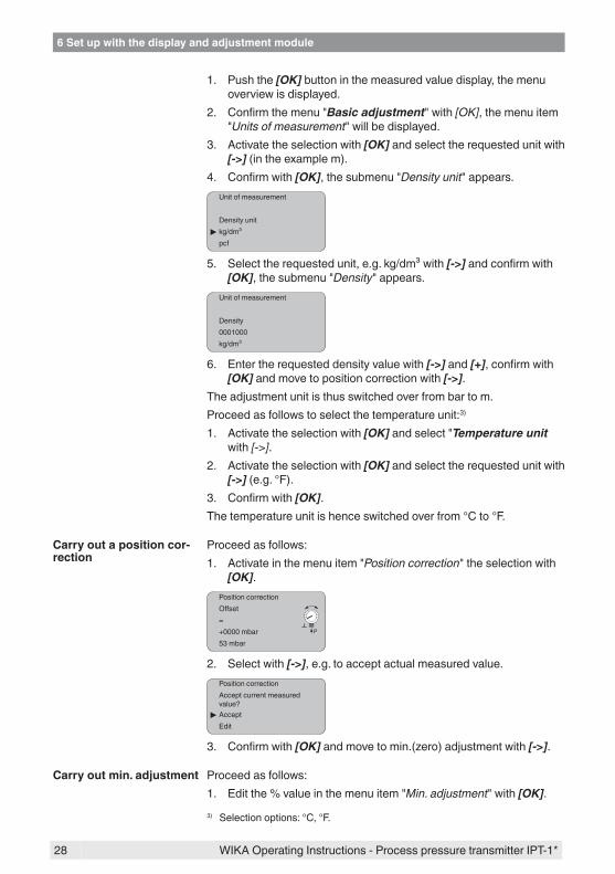
Inthemenuitem"Adjustment unit"youselectthephysicalunitinwhich the adjustment should be carried out, e.g. mbar, bar, psi…Thepositioncorrectioncompensatestheinfluenceofthemountingpositionorstaticpressureonthemeasurement.Itdoesnotinfluencethe adjustment values.
Information:The steps 1, 3 and 4 are not necessary for instruments which are alreadypresetaccordingtocustomerspecifications!Youcanfindthedataonthetypelabelontheinstrumentorinthemenu items of the min./max. adjustment.The display and adjustment module enables the adjustment without fillingorpressure.Thankstothis,youcancarryoutyoursettingsalready in the workshop without the instrument having to be installed.The actual measured value is also displayed in the menu items for min./max. adjustment.
In this menu item you select the adjustment unit as well as the unit for the temperature indication in the display.To select the adjustment unit (in the example switching over from bar to mbar), proceed as follows:2)
1. Push the [OK] button in the measured value display, the menu overview is displayed.
Basic adjustmentDisplayDiagnosticsServiceInfo
2. Confirmthemenu"Basic adjustment"with[OK], the menu item "Unit"willbedisplayed.
UnitUnitofmeasurement
barTemperature unit
°C
3. Activate the selection with [OK]andselect"Units of measure-ment with [->].
4. Activate the selection with [OK] and select the requested unit with [->] (in the example mbar).
5. Confirmwith[OK] and move to position correction with [->].The adjustment unit is thus switched over from bar to mbar.
Information:When switching over to adjustment in a height unit (in the example from bar to m), the density also has to be entered.Proceed as follows:
Select unit
2) Selection options: mbar, bar, psi, Pa, kPa, MPa, inHg, mmHg, inH2O, mmH2O.
28
6 Set up with the display and adjustment module
WIKA Operating Instructions - Process pressure transmitter IPT-1*
1. Push the [OK] button in the measured value display, the menu overview is displayed.
2. Confirmthemenu"Basic adjustment"with[OK], the menu item "Units of measurement"willbedisplayed.
3. Activate the selection with [OK] and select the requested unit with [->] (in the example m).
4. Confirmwith[OK],thesubmenu"Density unit"appears.Unitofmeasurement
Density unit kg/dm³
pcf
5. Select the requested unit, e.g. kg/dm³ with [->]andconfirmwith[OK],thesubmenu"Density"appears.
Unitofmeasurement
Density0001000kg/dm³
6. Enter the requested density value with [->] and [+],confirmwith[OK] and move to position correction with [->].
The adjustment unit is thus switched over from bar to m.Proceed as follows to select the temperature unit:3)
1. Activate the selection with [OK]andselect"Temperature unit with [->].
2. Activate the selection with [OK] and select the requested unit with [->] (e.g. °F).
3. Confirmwith[OK].The temperature unit is hence switched over from °C to °F.
Proceed as follows:1. Activateinthemenuitem"Position correction"theselectionwith
[OK].Position correctionOffset
P
=+0000 mbar53 mbar
2. Select with [->], e.g. to accept actual measured value.Position correctionAccept current measured value?
AcceptEdit
3. Confirmwith[OK] and move to min.(zero) adjustment with [->].
Proceed as follows:1. Editthe%valueinthemenuitem"Min. adjustment"with[OK].
Carry out a position cor-rection
Carry out min. adjustment
3) Selection options: °C, °F.

29
6 Set up with the display and adjustment module
WIKA Operating Instructions - Process pressure transmitter IPT-1*
Min. adjustment+000.0 %=+0000.0 mbar
0000.0 mbar
2. Set the requested percentage value with [+] and [->].3. Confirmwith[OK] and edit the requested mbar value.4. Set the requested mbar value with [+] and [->].5. Confirmwith[+] and move to max. adjustment with [->].Themin.adjustmentisfinished.
Information:Foranadjustmentwithfilling,simplyentertheactualmeasuredvalueindicated at the bottom of the display.Iftheadjustmentrangesareexceeded,themessage"Outside param-eter limits"appears.Theeditingprocedurecanbeabortedwith[ESC] or the displayed limit value can be accepted with [OK].
Proceed as follows:1. Editthe%valueinthemenuitem"Max. adjustment"with[OK].
Max. adjustment+100.0 %=+1000.0 mbar
0000.0 mbar
Information:The displayed pressure for 100 % corresponds to the nominal meas-uring range of the sensor (in the above example 1 bar = 1000 mbar).2. Set the requested percentage value with [->] and [OK].3. Confirmwith[OK] and edit the requested mbar value.4. Set the requested mbar value with [+] and [->].5. Confirmwith[OK] and move to the menu overview with [ESC].Themax.adjustmentisfinished.
Information:Foranadjustmentwithfilling,simplyentertheactualmeasuredvalueindicated at the bottom of the display.Iftheadjustmentrangesareexceeded,themessage"Outside param-eter limits"appears.Theeditingprocedurecanbeabortedwith[ESC] or the displayed limit value can be accepted with [OK].
Process pressure measurement
Set up IPT-1* in the following sequence:1. Selectapplication"Processpressuremeasurement"2. Select the unit of measurement3. Carry out a position correction4. Carrying out zero adjustment5. Carry out span adjustment
Carry out max. adjust-ment
Parameter adjustment "Process pressure meas-urement"
30
6 Set up with the display and adjustment module
WIKA Operating Instructions - Process pressure transmitter IPT-1*
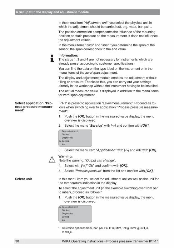
Inthemenuitem"Adjustment unit"youselectthephysicalunitinwhich the adjustment should be carried out, e.g. mbar, bar, psi…Thepositioncorrectioncompensatestheinfluenceofthemountingpositionorstaticpressureonthemeasurement.Itdoesnotinfluencethe adjustment values.Inthemenuitems"zero"and"span"youdeterminethespanofthesensor, the span corresponds to the end value.
Information:The steps 1, 3 and 4 are not necessary for instruments which are alreadypresetaccordingtocustomerspecifications!Youcanfindthedataonthetypelabelontheinstrumentorinthemenu items of the zero/span adjustment.The display and adjustment module enables the adjustment without fillingorpressure.Thankstothis,youcancarryoutyoursettingsalready in the workshop without the instrument having to be installed.The actual measured value is displayed in addition to the menu items for zero/span adjustment.
IPT-1*ispresettoapplication"Levelmeasurement".Proceedasfol-lowswhenswitchingovertoapplication"Processpressuremeasure-ment":1. Push the [OK] button in the measured value display, the menu
overview is displayed.2. Selectthemenu"Service"with[->]andconfirmwith[OK].
Basic adjustmentDisplayDiagnostics
ServiceInfo
3. Selectthemenuitem"Application"with[->] and edit with [OK].
Warning:Notethewarning:"Output can change".4. Select with [->]"OK"andconfirmwith[OK].5. Select"Process pressure"fromthelistandconfirmwith[OK].
In this menu item you select the adjustment unit as well as the unit for the temperature indication in the display.To select the adjustment unit (in the example switching over from bar to mbar), proceed as follows:4)
1. Push the [OK] button in the measured value display, the menu overview is displayed.
Basic adjustmentDisplayDiagnosticsServiceInfo
Select application "Pro-cess pressure measure-ment"
Select unit
4) Selection options: mbar, bar, psi, Pa, kPa, MPa, inHg, mmHg, inH2O, mmH2O.

31
6 Set up with the display and adjustment module
WIKA Operating Instructions - Process pressure transmitter IPT-1*
2. Confirmthemenu"Basic adjustment"with[OK], the menu item "Unit"willbedisplayed.
UnitUnitofmeasurement
barTemperature unit
°C
3. Activate the selection with [OK]andselect"Units of measure-ment with [->].
4. Activate the selection with [OK] and select the requested unit with [->] (in the example mbar).
5. Confirmwith[OK] and move to position correction with [->].The adjustment unit is thus switched over from bar to mbar.Proceed as follows to select the temperature unit:5)
1. Activate the selection with [OK]andselect"Temperature unit with [->].
2. Activate the selection with [OK] and select the requested unit with [->] (e.g. °F).
3. Confirmwith[OK].The temperature unit is hence switched over from °C to °F.
Proceed as follows:1. Activateinthemenuitem"Position correction"theselectionwith
[OK].Position correctionOffset
P
=+0000 mbar53 mbar
2. Select with [->], e.g. to accept actual measured value.Position correctionAccept current measured value?
AcceptEdit
3. Confirmwith[OK] and move to min.(zero) adjustment with [->].
Proceed as follows:1. Editthembarvalueinthemenuitem"zero"with[OK].
Zero000.0 %
P
=+0000.0 mbar
0000.0 mbar
2. Set the requested mbar value with [+] and [->].3. Confirmwith[+] and move to span adjustment with [->].Thezeroadjustmentisfinished.
Carry out a position cor-rection
Carrying out zero adjust-ment
5) Selection options: °C, °F.

32
6 Set up with the display and adjustment module
WIKA Operating Instructions - Process pressure transmitter IPT-1*
Information:The zero adjustment shifts the value of the span adjustment. The span,i.e.thedifferencebetweenthesevalues,however,remainsunchanged.
Information:For an adjustment with pressure, simply enter the actual measured value indicated at the bottom of the display.Iftheadjustmentrangesareexceeded,themessage"Outside param-eter limits"appears.Theeditingprocedurecanbeabortedwith[ESC] or the displayed limit value can be accepted with [OK].
Proceed as follows:1. Editthembarvalueinthemenuitem"span"with[OK].
Span100.0 %
P
=+1000.0 mbar
0000.0 mbar
Information:The displayed pressure for 100 % corresponds to the nominal meas-uring range of the sensor (in the above example 1 bar = 1000 mbar).2. Set the requested mbar value with [->] and [OK].3. Confirmwith[OK] and move to the menu overview with [ESC].Thespanadjustmentisfinished.
Information:For an adjustment with pressure, simply enter the actual measured value indicated at the bottom of the display.Iftheadjustmentrangesareexceeded,themessage"Outside param-eter limits"appears.Theeditingprocedurecanbeabortedwith[ESC] or the displayed limit value can be accepted with [OK].
This function enables reading out parameter adjustment data as well as writing parameter adjustment data into the sensor via the display and adjustment module. A description of the function is available in theoperatinginstructionsmanual"Display and adjustment module".The following data are read out or written with this function:
• Measured value presentation• Adjustment• Damping• Linearization curve• Sensor-TAG• Displayed value• Display unit• Scaling• Current output• Unitofmeasurement• Language
The following safety-relevant data are not read out or written:
Carry out span adjust-ment
Copy sensor data

33
6 Set up with the display and adjustment module
WIKA Operating Instructions - Process pressure transmitter IPT-1*
• SIL• HART mode6)
• PIN• Application
Copy sensor data
Copy sensor data?
Basic adjustmentThe reset function resets all parameters adjusted by the user to the delivery status and the peak values to the actual values.
Reset
Select reset?
ResetBasic adjustmentPeak value, measured valuePeak value, temperature
Basic adjustmentThe"Reset""Basic adjustment"resetsthevaluesofthefollowingmenu items:
Menu section Function Resetvalue
Basic settings Zero/Min. adjustment Measuring range begin
Span/Max. adjustment Measuring range end
Density 1 kg/l
Density unit kg/l
Damping 1 s
Linearization Linear
Sensor-TAG Sensor
Display Displayed value 1 bar
Displayed value 2 %
Display unit Volume/l
Scaling 0.00 to 100.0
Decimal point indication 8888.8
Service Current output - charac-teristics
4 … 20 mA
Current output - failure < 3.6 mA
Current output - min. current
> 3.8 mA
Reset
6) With instruments with signal output 4 … 20 mA/HART

34
6 Set up with the display and adjustment module
WIKA Operating Instructions - Process pressure transmitter IPT-1*
Menu section Function Resetvalue
Current output - max. current
> 20.5 mA
The values of the following menu items are notresetwith"Reset:
Menu section Function Resetvalue
Basic settings Unitofmeasurement Noreset
Temperature unit Noreset
Position correction Noreset
Display Backlight Noreset
Service SIL Noreset
Language Noreset
HART mode6) Noreset
Application Noreset
Peak valueThe min. and max. temperature or pressure values are each reset to the actual value.
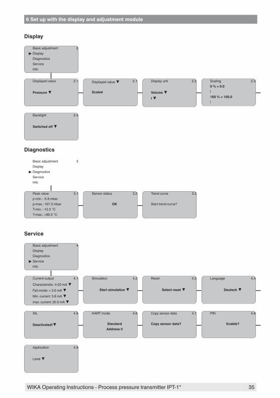
Additional adjustment and diagnosis options such as e.g. scaling, simulation or trend curve presentation are shown in the following menuschematic.Youwillfindadetaileddescriptionofthesemenuitemsintheoperatinginstructionsmanual"Display and adjustment module".
6.5 Menu schematicInformation:Depending on the version and application, the highlighted menu windows may not always be available.
Basic adjustment
Basic adjustment 1DisplayDiagnosticsServiceInfo
Unit 1.1Unitofmeasurement
bar Temperature unit
°C
Position correction 1.2Offset
P
=0.2 mbar0000 mbar
Min. adjustment 1.3000.0 %=0.0 mbar
0.0 mbar
Max. adjustment 1.4100.00 %=100.00 mbar
0.0 mbar
Damping 1.5
1 s
Linearization curve 1.6
Linear
Sensor-TAG 1.7
Sensor
Optional settings
35
6 Set up with the display and adjustment module
WIKA Operating Instructions - Process pressure transmitter IPT-1*
Display
Basic adjustment 2Display
DiagnosticsServiceInfo
Displayed value 2.1
Pressure
Displayed value 2.1
Scaled
Display unit 2.2
Volume l
Scaling 2.30 % = 0.0l100 % = 100.0l
Backlight 2.4
Switchedoff
Diagnostics
Basic adjustment 3Display
DiagnosticsServiceInfo
Peak value 3.1p-min.: -5.8 mbarp-max.: 167.5 mbarT-min.: -12.5 °CT-max.: +85.5 °C
Sensor status 3.2
OK
Trend curve 3.3
Start trend curve?
Service
Basic adjustment 4DisplayDiagnostics
ServiceInfo
Current output 4.1
Characteristic: 4-20 mA Fail.mode: < 3.6 mA Min. current: 3.8 mA max. current: 20.5 mA
Simulation 4.2
Start simulation
Reset 4.3
Select reset
Language 4.4
Deutsch
SIL 4.5
Deactivated!
HART mode 4.6
StandardAddress 0
Copy sensor data 4.7
Copy sensor data?
PIN 4.8
Enable?
Application 4.9
Level
36
6 Set up with the display and adjustment module
WIKA Operating Instructions - Process pressure transmitter IPT-1*
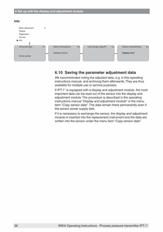
Info
Basic adjustment 5DisplayDiagnosticsService
Info
Instrument type 5.1
Serial number
Date of manufacture 5.2
Software version
Last change using PC 5.3 Sensor characteristics 5.4
Display now?
6.10 Saving the parameter adjustment dataWe recommended noting the adjusted data, e.g. in this operating instructions manual, and archiving them afterwards. They are thus available for multiple use or service purposes.If IPT-1* is equipped with a display and adjustment module, the most important data can be read out of the sensor into the display and adjustment module. The procedure is described in the operating instructionsmanual"Display and adjustment module"inthemenuitem"Copy sensor data".Thedataremaintherepermanentlyevenifthe sensor power supply fails.If it is necessary to exchange the sensor, the display and adjustment module is inserted into the replacement instrument and the data are writtenintothesensorunderthemenuitem"Copy sensor data".

37
7 Set up with PACTware and other adjustment programs
WIKA Operating Instructions - Process pressure transmitter IPT-1*
7 Set up with PACTware and other adjustment programs
7.1 Connect the PC
3
1
2~
=
Power supply
PACTware /DTM
HART-Modem TM
Fig. 22: Connecting the PC to the signal cable1 RS232 connection2 HART resistor 250 Ω3 IPT-1*
Necessarycomponents:
• IPT-1*• PC with PACTware and suitable WIKA DTM• HART modem• HARTresistanceapprox.250Ω• Power supply unit
Note:For power supply units with integrated HART resistance (inner resist-anceapprox.250Ω),thereisnoadditionalexternalresistanceneces-sary.StandardExseparatorsareoftenprovidedwithasufficientlyhigh current limitation resistance. In such cases, the modem can be connected in parallel to the 4 … 20 mA cable.
7.2 Parameter adjustment with PACTwareThe further setup steps with detailed descriptions can be found in the online help of PACTware and the DTMs.
Note:Keep in mind that for the setup of model IPT-1*, the current version of the DTM-Collection must be used.The latest DTM Collection and PACTware version can be downloaded free of charge via the Internet.
Connecting the PC to the signal cable
38
7 Set up with PACTware and other adjustment programs
WIKA Operating Instructions - Process pressure transmitter IPT-1*
7.3 Parameter adjustment with AMS™ and PDMFor WIKA sensors, instrument descriptions for the adjustment programs AMS™ and PDM are available as DD or EDD. The instru-ment descriptions are already implemented in the current versions of AMS™ and PDM. For older versions of AMS™ and PDM, a free-of-charge download is available via Internet. Go via www.wika.comtotheitem"Service".
7.4 Saving the parameter adjustment dataIt is recommended to document or save the parameter adjustment data. That way they are available for multiple use or service purposes.The WIKA DTM Collection and PACTware in the licensed, profession-al version provide suitable tools for systematic project documentation and storage.

39
8Maintenanceandfaultrectification
WIKA Operating Instructions - Process pressure transmitter IPT-1*
8 Maintenanceandfaultrectification
8.1 MaintenanceIf the instrument is used properly, no special maintenance is required in normal operation.Insomeapplications,productbuilduponthediaphragmcaninfluencethe measuring result. Depending on the sensor and application, take precautions to ensure that heavy buildup, and especially a hardening thereof, is avoided.
The diaphragm should be cleaned if necessary. For this reason, the resistance of the materials to cleaning processes must be ensured. The large variety of chemical seal applications makes special clean-ing instructions for each application necessary. Please contact the agency serving you.
Caution:On instruments with a chemical seal, never clean the separating diaphragmmechanicallywithhardobjects,suchastools!Thiscandamagethediaphragmandleadtofillingoilleaks.
8.2 RectifyfaultsThe operator of the system is responsible for taking suitable meas-ures to rectify faults.
IPT-1*offersmaximumreliability.Nevertheless,faultscanoccurdur-ing operation. These may be caused by the following, e.g.:
• Sensor• Process• Voltage supply• Signal processing
Thefirstmeasurestobetakenaretochecktheoutputsignalsaswellas to evaluate the error messages via the display and adjustment module. The procedure is described below. Further comprehensive diagnostics can be carried out on a PC with the software PACTware and the suitable DTM. In many cases, the causes can be determined andthefaultsrectifiedthisway.
Connect a multimeter in the suitable measuring range according to the wiring plan.
Error code Cause Rectification
4 … 20 mA signal not stable
Levelfluctuations – Set the integration time via the display and adjustment module or PACTware
Noatmosphericpres-sure compensation
– Check the pressure compensation inthehousingandcleanthefilterelement, if necessary
Maintenance
Cleaning
Reactionwhenmalfunc-tions occur
Failure reasons
Faultrectification
Check the 4 … 20 mA signal

40
8Maintenanceandfaultrectification
WIKA Operating Instructions - Process pressure transmitter IPT-1*
Error code Cause Rectification
4 … 20 mA signal miss-ing
Connection to volt-age supply wrong
– Check connection according to chapter"Connection steps"andif necessary, correct according to chapter"Wiring plan"
Nopowersupply – Check cables for breaks; repair if necessary
Operating voltage too low or load resist-ance too high
– Check, adapt if necessary
Current sig-nal greater than 22 mA or less than 3.6 mA
Electronics module or measuring cell de-fective
– Exchange the instrument or send it in for repair
In Ex applications, the regulations for the wiring of intrinsically safe circuits must be observed.
Error code Cause Rectification
E013 no measured value available1)
– Exchange the instrument or send it in for repair
E017 Adjustment span too small
– repeatwithmodifiedvalues
E036 no operable sensor software
– Carry out a software update or send instrument for repair
E041 Hardware error – Exchange the instrument or send it in for repair
Depending on the reason for the fault and the measures taken, the stepsdescribedinchapter"Set up"mayhavetobecarriedoutagain.
8.3 Instrument repairYoucanfindinformationforareturnshipmentunder"Service"onourlocal website.If a repair is necessary, please proceed as follows:
• Complete one form for each instrument• If necessary, state a contamination• Clean the instrument and pack it damage-proof• Attach the completed form and possibly also a safety data sheet to
the instrument
Error messages via the display and adjustment module
Reactionafterfaultrecti-fication

41
9 Dismounting
WIKA Operating Instructions - Process pressure transmitter IPT-1*
9 Dismounting
9.1 Dismounting stepsWarning:Before dismounting, be aware of dangerous process conditions such as e.g. pressure in the vessel, high temperatures, corrosive or toxic products etc.Takenoteofchapters"Mounting"and"Connecting to power supply"and carry out the listed steps in reverse order.
9.2 DisposalThe instrument consists of materials which can be recycled by spe-cialised recycling companies. We use recyclable materials and have designed the parts to be easily separable.Materials:seechapter"Technical data"If you have no way to dispose of the old instrument properly, please contact us concerning return and disposal.
42
10 Supplement
WIKA Operating Instructions - Process pressure transmitter IPT-1*
10 Supplement
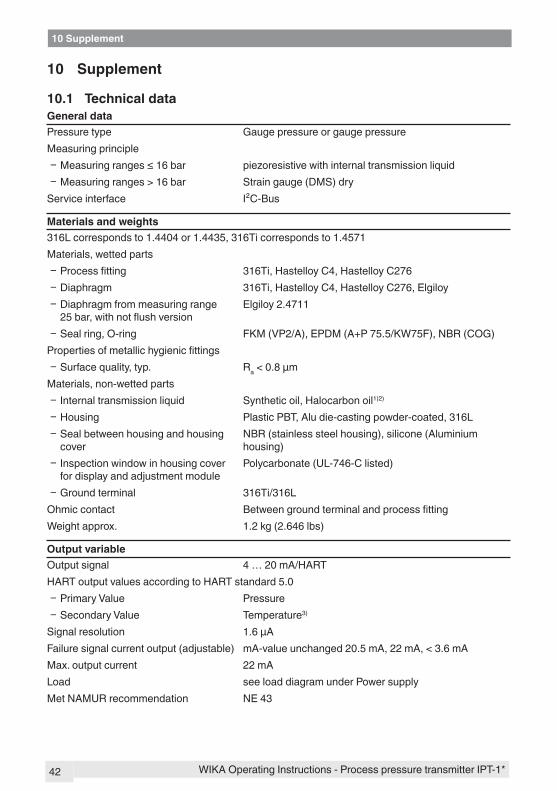
10.1 Technical dataGeneral dataPressure type Gauge pressure or gauge pressureMeasuring principle
Ʋ Measuringranges≤16bar piezoresistive with internal transmission liquid Ʋ Measuring ranges > 16 bar Strain gauge (DMS) dry
Service interface I²C-Bus
Materials and weights316L corresponds to 1.4404 or 1.4435, 316Ti corresponds to 1.4571Materials, wetted parts
Ʋ Processfitting 316Ti, Hastelloy C4, Hastelloy C276 Ʋ Diaphragm 316Ti, Hastelloy C4, Hastelloy C276, Elgiloy Ʋ Diaphragm from measuring range 25bar,withnotflushversion
Elgiloy 2.4711
Ʋ Seal ring, O-ring FKM(VP2/A),EPDM(A+P75.5/KW75F),NBR(COG)Propertiesofmetallichygienicfittings
Ʋ Surface quality, typ. Ra < 0.8 µmMaterials, non-wetted parts
Ʋ Internal transmission liquid Synthetic oil, Halocarbon oil1)2)
Ʋ Housing Plastic PBT, Alu die-casting powder-coated, 316L Ʋ Seal between housing and housing cover
NBR(stainlesssteelhousing),silicone(Aluminiumhousing)
Ʋ Inspection window in housing cover for display and adjustment module
Polycarbonate(UL-746-Clisted)
Ʋ Ground terminal 316Ti/316LOhmic contact BetweengroundterminalandprocessfittingWeight approx. 1.2 kg (2.646 lbs)
Output variableOutput signal 4 … 20 mA/HARTHART output values according to HART standard 5.0
Ʋ Primary Value Pressure Ʋ Secondary Value Temperature3)
Signal resolution 1.6 µAFailure signal current output (adjustable) mA-value unchanged 20.5 mA, 22 mA, < 3.6 mAMax. output current 22 mALoad see load diagram under Power supplyMetNAMURrecommendation NE43

43
10 Supplement
WIKA Operating Instructions - Process pressure transmitter IPT-1*
Dynamic behaviour outputRun-up time approx. 10 s
90 %
100 %
10 %
t tT At
tS
21
Fig. 23: Sudden change of the process variable. tT: dead time; tA: rise time; tS: jump response time1 Process variable2 Output signal
Dead time ≤150msRise time ≤100ms(10…90%)Step response time ≤250ms(ti:0s,10…90%)Damping (63 % of the input variable) 0 … 999 s, adjustable
Input variableAdjustmentAdjustment range of the min./max. adjustment relating to the nominal measuring range:
Ʋ Min. -5 … +95 % Ʋ Max. -5 … +105 %
Adjustment range of the zero/span adjustment relating to the nominal measuring range: Ʋ zero -5 … +95 % Ʋ Span -5 … +105 %
Recommended max. turn down 10 : 1 (no limitation)Nominalmeasuringrangesandoverloadcapabilityinbar/kPaThespecificationsareonlyanoverviewandrefertothemeasuringcell.Limitationsduetothema-terialandversionoftheprocessfittingarepossible.Thespecificationsonthenameplateapply.
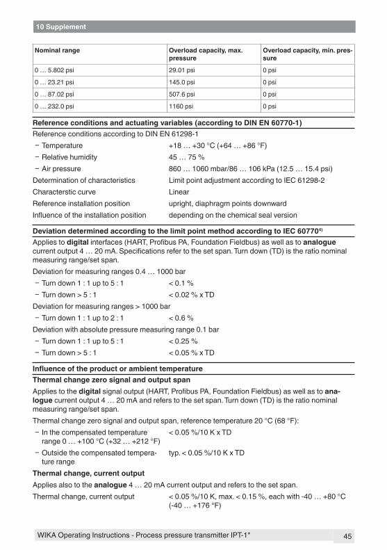
Nominalrange Overload capacity, max. pressure
Overload capacity, min. pres-sure
Gauge pressure
0 … +0.4 bar/0 … +40 kPa +2 bar/+200 kPa -1 bar/-100 kPa
0 … +1.6 bar/0 … +160 kPa +10 bar/+1000 kPa -1 bar/-100 kPa
0 … +16 bar/0 … +1.6 MPa +80 bar/+8 MPa -1 bar/-100 kPa
0 … +40 bar/0 … +4 MPa +80 bar/+8 MPa -1 bar/-100 kPa
0 … +100 bar/0 … +10 MPa +200 bar/+20 MPa -1 bar/-100 kPa

44
10 Supplement
WIKA Operating Instructions - Process pressure transmitter IPT-1*
Nominalrange Overload capacity, max. pressure
Overload capacity, min. pres-sure
0 … +250 bar/0 … +25 MPa +500 bar/+50 MPa -1 bar/-100 kPa
0 … +600 bar/0 … +60 MPa +1200 bar/+120 MPa -1 bar/-100 kPa
0 … +1000 bar/0 … +100 MPa +1500 bar/+150 MPa -1 bar/-100 kPa
-1 … 0 bar/-100 … 0 kPa +5 bar/+500 kPa -1 bar/-100 kPa
-1 … +0.6 bar/-100 … +60 kPa +10 bar/+1000 kPa -1 bar/-100 kPa
-1 … +3 bar/-100 … +300 kPa +17 bar/+1700 kPa -1 bar/-100 kPa
-1 … +5 bar/-100 … +500 kPa +35 bar/+3500 kPa -1 bar/-100 kPa
-1 … +15 bar/-100 … +1.5 MPa +80 bar/+8 MPa -1 bar/-100 kPa
-0.1 … +0.3 bar/-10 … +30 kPa +2 bar/+200 kPa -1 bar/-100 kPa
-0.2 … +0.2 bar/-20 … +20 kPa +2 bar/+200 kPa -1 bar/-100 kPa
Absolute pressure
0 … 0.4 bar/0 … 40 kPa 2 bar/200 kPa 0 bar abs.
0 … 1.6 bar/0 … 160 kPa 10 bar/1000 kPa 0 bar abs.
0 … 6 bar/0 … 600 kPa 35 bar/3500 kPa 0 bar abs.
0 … 16 bar/0 … 1.6 MPa 80 bar/8 MPa 0 bar abs.
NominalmeasuringrangesandoverloadcapacityinpsiThespecificationsareonlyanoverviewandrefertothemeasuringcell.Limitationsduetothema-terialandversionoftheprocessfittingarepossible.Thespecificationsonthenameplateapply.
Nominalrange Overload capacity, max. pressure
Overload capacity, min. pres-sure
Gauge pressure
0 … +5.801 psig +29.00 psig -14.50 psig
0 … +23.21 psig +145.0 psig -14.50 psi
0 … +232.1 psig +1160 psig -14.5 psig
0 … +580.2 psig +1160 psig -14.50 psig
0 … +1450 psig +2901 psig -14.50 psig
0 … +3626 psig +7252 psig -14.50 psig
0 … +8702 psig +17404 psig -14.50 psig
0 … +14504 psig +21756 psig -14.50 psig
-14.50 … 0 psig +72.52 psig -14.50 psig
-1 … +8.702 psig +145.0 psig -14.50 psig
-1 … +43.51 psig +246.6 psig -14.50 psig
-1 … +72.52 psig +507.6 psig -14.50 psig
-1 … +217.6 psig +1160 psig -14.50 psig
-1.450 … +4.351 psig +29.01 psig -14.50 psig
-2.901 … +2.901 psig +29.01 psig -14.50 psig
Absolute pressure
45
10 Supplement
WIKA Operating Instructions - Process pressure transmitter IPT-1*
Nominalrange Overload capacity, max. pressure
Overload capacity, min. pres-sure
0 … 5.802 psi 29.01 psi 0 psi
0 … 23.21 psi 145.0 psi 0 psi
0 … 87.02 psi 507.6 psi 0 psi
0 … 232.0 psi 1160 psi 0 psi
Referenceconditionsandactuatingvariables(accordingtoDINEN60770-1)ReferenceconditionsaccordingtoDINEN61298-1
Ʋ Temperature +18 … +30 °C (+64 … +86 °F) Ʋ Relative humidity 45 … 75 % Ʋ Air pressure 860 … 1060 mbar/86 … 106 kPa (12.5 … 15.4 psi)
Determination of characteristics Limit point adjustment according to IEC 61298-2Characterstic curve LinearReference installation position upright, diaphragm points downwardInfluenceoftheinstallationposition depending on the chemical seal version
Deviation determined according to the limit point method according to IEC 607704)
Applies to digitalinterfaces(HART,ProfibusPA,FoundationFieldbus)aswellastoanalogue currentoutput4…20mA.Specificationsrefertothesetspan.Turndown(TD)istherationominalmeasuring range/set span.Deviation for measuring ranges 0.4 … 1000 bar
Ʋ Turn down 1 : 1 up to 5 : 1 < 0.1 % Ʋ Turn down > 5 : 1 < 0.02 % x TD
Deviation for measuring ranges > 1000 bar Ʋ Turn down 1 : 1 up to 2 : 1 < 0.6 %
Deviation with absolute pressure measuring range 0.1 bar Ʋ Turn down 1 : 1 up to 5 : 1 < 0.25 % Ʋ Turn down > 5 : 1 < 0.05 % x TD
InfluenceoftheproductorambienttemperatureThermal change zero signal and output spanApplies to the digitalsignaloutput(HART,ProfibusPA,FoundationFieldbus)aswellastoana-logue current output 4 … 20 mA and refers to the set span. Turn down (TD) is the ratio nominal measuring range/set span.Thermal change zero signal and output span, reference temperature 20 °C (68 °F):
Ʋ In the compensated temperature range 0 … +100 °C (+32 … +212 °F)
< 0.05 %/10 K x TD
Ʋ Outside the compensated tempera-ture range
typ. < 0.05 %/10 K x TD
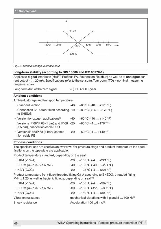
Thermal change, current outputApplies also to the analogue 4 … 20 mA current output and refers to the set span.Thermal change, current output < 0.05 %/10 K, max. < 0.15 %, each with -40 … +80 °C
(-40 … +176 °F)
46
10 Supplement
WIKA Operating Instructions - Process pressure transmitter IPT-1*
0,15 %
-0,15 %
-40°C -20°C 20°C 40°C 60°C 80°C
Fig. 24: Thermal change, current output
Long-termstability(accordingtoDIN16086andIEC60770-1)Applies to digitalinterfaces(HART,ProfibusPA,FoundationFieldbus)aswellastoanalogue cur-rentoutput4…20mA.Specificationsrefertothesetspan.Turndown(TD)=nominalmeasuringrange/set span.Long-term drift of the zero signal < (0.1 % x TD)/year
Ambient conditionsAmbient, storage and transport temperature
Ʋ Standard version -40 … +80 °C (-40 … +176 °F) Ʋ ConnectionG1Afront-flushaccordingto EHEDG
-10 … +80 °C (+14 … +176 °F)
Ʋ Version for oxygen applications5) -40 … +60 °C (-40 … +140 °F) Ʋ Versions IP 66/IP 68 (1 bar) and IP 68 (25bar),connectioncablePUR
-20 … +80 °C (-4 … +176 °F)
Ʋ Version IP 66/IP 68 (1 bar), connec-tion cable PE
-20 … +60 °C (-4 … +140 °F)
Process conditionsThespecificationsareusedasanoverview.Forpressurestageandproducttemperaturethespeci-ficationsonthetypeplateareapplicable.Product temperature standard, depending on the seal6)
Ʋ FKM (VP2/A) -20 … +105 °C (-4 … +221 °F) Ʋ EPDM (A+P 75.5/KW75F) -40 … +105 °C (-40 … +221 °F) Ʋ NBR(COG) -20 … +105 °C (-4 … +221 °F)
Producttemperaturefront-flushthreadedfittingG1AaccordingtoEHEDG,threadedfittingM44x1.25aswellashygienicfittings,dependingonseal7)8)
Ʋ FKM (VP2/A) -20 … +150 °C (-4 … +302 °F) Ʋ EPDM (A+P 75.5/KW75F) -30 … +150 °C (-22 … +302 °F) Ʋ NBR(COG) -20 … +150 °C (-4 … +302 °F)
Vibration resistance mechanical vibrations with 4 g and 5 … 100 Hz9)
Shock resistance Acceleration 100 g/6 ms10)

47
10 Supplement
WIKA Operating Instructions - Process pressure transmitter IPT-1*
Electromechanical data - version IP 66/IP 67Cable entry/plug11)
Ʋ Single chamber housing – 1 x cable gland M20 x 1.5 (cable: ø 5 … 9 mm), 1 x blind plug M20 x 1.5
or: – 1xclosingcap½NPT,1xblindplug½NPT
or: – 1xplug(dependingontheversion),1xblindstopperM20x1.5
Ʋ Double chamber housing – 1 x cable entry M20 x 1.5 (cable: ø 5 … 9 mm), 1 x blind plug M20 x 1.5; plug M12 x 1 for the external display and adjustment unit (optional)
or: – 1xclosingcap½NPT,1xblindplug½NPT,plugM12 x 1 for the external display and adjustment unit (optional)
or: – 1 x plug (depending on the version), 1 x blind plug M20 x 1.5; plug M12 x 1 for the external display and adjustment unit (optional)
Spring-loaded terminals for wire cross-section up to
2.5 mm² (AWG 14)
Display and adjustment moduleVoltage supply and data transmission through the sensorIndication LC display in dot matrixAdjustment elements 4 keysProtection rating
Ʋ unassembled IP 20 Ʋ mounted into the sensor without cover IP 40
Material Ʋ Housing ABS Ʋ Inspection window Polyester foil
Voltage supplyOperating voltage
Ʋ Non-Exinstrument 14 … 36 V DC Ʋ Ex-ia instrument 14 … 30 V DC Ʋ Ex-d instrument 18 … 36 V DC
Operating voltage with illuminated display and adjustment module Ʋ Non-Exinstrument 20 … 36 V DC Ʋ Ex-ia instrument 20 … 30 V DC Ʋ Ex-d instrument 20 … 36 V DC
Permissible residual ripple Ʋ < 100 Hz Uss < 1 V
48
10 Supplement
WIKA Operating Instructions - Process pressure transmitter IPT-1*
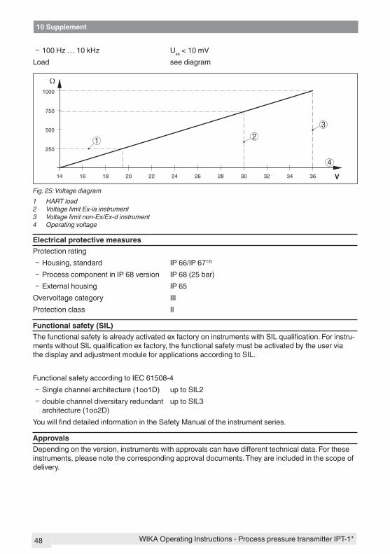
Ʋ 100 Hz … 10 kHz Uss < 10 mVLoad see diagram
1000
750
500
250
14 1816 20 22 24 26 28 30 32 34 36
Ω
V
4
1 2
3
Fig. 25: Voltage diagram1 HART load2 Voltage limit Ex-ia instrument3 Voltage limit non-Ex/Ex-d instrument4 Operating voltage
Electrical protective measuresProtection rating
Ʋ Housing, standard IP 66/IP 6712)
Ʋ Process component in IP 68 version IP 68 (25 bar) Ʋ External housing IP 65
Overvoltage category IIIProtection class II
Functional safety (SIL)ThefunctionalsafetyisalreadyactivatedexfactoryoninstrumentswithSILqualification.Forinstru-mentswithoutSILqualificationexfactory,thefunctionalsafetymustbeactivatedbytheuserviathe display and adjustment module for applications according to SIL.
Functional safety according to IEC 61508-4 Ʋ Single channel architecture (1oo1D) up to SIL2 Ʋ double channel diversitary redundant architecture (1oo2D)
up to SIL3
YouwillfinddetailedinformationintheSafetyManualoftheinstrumentseries.
ApprovalsDependingontheversion,instrumentswithapprovalscanhavedifferenttechnicaldata.Fortheseinstruments, please note the corresponding approval documents. They are included in the scope of delivery.

49
10 Supplement
WIKA Operating Instructions - Process pressure transmitter IPT-1*
10.2 Dimensions
Plastic housing~ 69 mm(2.72")
ø 77 mm(3.03")
112
mm
(4.4
1")
M20x1,5/½ NPT
~ 84 mm (3.31")
M16x1,5
112
mm
(4.4
1")
M20x1,5/½ NPT1 2
ø 84 mm(3.31")
Fig. 26: Housing versions in protection IP 66/IP 68 (0.2 bar) - with integrated display and adjustment module the housing is 9 mm/0.35 in higher1 Single chamber version2 Double chamber version
Aluminium housing
21
ø 84 mm (3.31")
~ 116 mm (4.57")
116
mm
(4.5
7")
M20x1,5M20x1,5/½ NPT
~ 87 mm (3.43")
M16x1,5
ø 84 mm(3.31")
120
mm
(4.7
2")
M20x1,5/½ NPT
Fig. 27: Housing versions in protection IP 66/IP 68 (0.2 bar) - with integrated display and adjustment module the housing is 9 mm/0.35 in higher1 Single chamber version2 Double chamber version

50
10 Supplement
WIKA Operating Instructions - Process pressure transmitter IPT-1*
Stainless steel housing~ 69 mm
(2.72")ø 77 mm
(3.03")
117
mm
(4.6
1")
M20x1,5/½ NPT
~ 59 mm(2.32")
ø 80 mm(3.15")
112
mm
(4.4
1")
M20x1,5/½ NPT
~ 87 mm (3.43")
M16x1,5
ø 84 mm(3.31")
120
mm
(4.7
2")
M20x1,5/½ NPT 321
Fig. 28: Housing versions in protection IP 66/IP 68 (0.2 bar) - with integrated display and adjustment module the housing is 9 mm/0.35 in higher1 Single chamber version, electropolished2 Single chamber version, precision casting3 Double chamber version, precision casting
External housing with IP 68 version
1
2
65 mm(2.56")
68 m
m(2
.68"
)92
mm
(3.6
2")
42 mm(1.65")
40mm(1.58")
110 mm x 90 mm (4.33" x 3.54")
~ 66 mm (2.6")
59 m
m (2
.32"
)
Fig. 29: IP 68 version with external housing - plastic version1 Lateral cable outlet2 Axial cable outlet

51
10 Supplement
WIKA Operating Instructions - Process pressure transmitter IPT-1*
1
2
65 mm(2.56")
68 m
m(2
.68"
)92
mm
(3.6
2")
42 mm(1.65")
40mm(1.58")
110 mm x 90 mm (4.33" x 3.54")
~ 66 mm (2.6")
59 m
m(2
.32"
)
Fig. 30: IP 68 version with external housing - stainless steel version1 Lateral cable outlet2 Axial cable outlet

52
10 Supplement
WIKA Operating Instructions - Process pressure transmitter IPT-1*
IPT-1*,threadedfitting
SW27
SW27
60°
23m
m(2
9 /32
")G ½ A
63m
m(2
31/ 6
4")
57m
m(2
1 /4"
)
15m
m(1
9 /32
")
3mm
(1/ 8
") ø 3mm (1/8") ø 6mm
(15/64")
½“NPT
¼“NPT
65m
m(2
9 /16
")
25m
m(6
3 /64
")
15m
m(1
9 /32
")20
mm
(25 /
32")
M 20x1,5
NDGD
ML
ø 4,8(3/16")
MI
SW27
60°
57m
m(2
1 /4"
)
12m
m(1
5 /32
")
M 16x1,5
ø 4,8(3/16")
Fig. 31: IPT-1* GD = G½ EN 837, ND = ½ NPT, ML = M16 x 1.5 inner, MI = M20 x 1.5 inner

53
10 Supplement
WIKA Operating Instructions - Process pressure transmitter IPT-1*
IPT-1*,front-flushconnection,part1
SW41
20,5
mm
(13 /
16")
G1B G½B
65 m
m(2
9 /16
")ø 30 mm (1 3/16")
SW60
22 m
m(5
5 /64
")
SW27
20,5
mm
(13 /
16")
ø 30 mm (1 3/16")
ø 18 mm (45/64")
G1½A 71 m
m(2
51/ 6
4") SW41
28 m
m(1
7 /64
")
G1B
68 m
m(2
43/ 6
4")
65 m
m(2
9 /16
")
85
G6 83
86
Fig. 32: IPT-1* 85 = G1 A front-flush 0 … 0.4 bar and 0 … 1.6 bar, 86 = G½ A front-flush > 1.6 bar, 84 = G1 A front-flush up to 150 °C according to EHEDG 0 … 0.4 bar and 0 … 16 bar

54
10 Supplement
WIKA Operating Instructions - Process pressure transmitter IPT-1*
IPT-1*,front-flushconnection,part2
51 m
m(2
1 /64
")
ø 84 mm (3 5/16")
RT RASA
ø64 mm (2 33/64")
82 m
m(3
15/ 6
4")
3T 3R
ø 65 mm (2 9/16")
ø 84 mm (3 5/16")
ø 105 mm (4 9/64")
82 m
m(3
15/ 6
4")
ø50 mm (1 31/32")
82 m
m(3
15/ 6
4")
81 m
m(3
3 /16
")
ø 74 mm (2 29/32")
Fig. 33: IPT-1*, SA = Tri-Clamp 2", RA = bolting DN 40/PN 40 according to DIN 11851, RT = Tri-Clamp 1½", 3T = DRD, 3R = Varivent Form F

55
Notes
WIKA Operating Instructions - Process pressure transmitter IPT-1*
56
Printing date:
WIKA Alexander Wiegand SE & Co. KGAlexander-Wiegand-Straße 3063911 KlingenbergGermanyPhone (+49) 9372/132-0Fax (+49) 9372 132-406E-mail: [email protected]
31543-EN
-130628
All statements concerning scope of delivery, application, practi-cal use and operating conditions of the sensors and processing systems correspond to the information available at the time of printing.
Process pressure transmitter IPT-1*