operating instructions type series ne - lyma. · pdf fileenglisch 2006-11 operating...
TRANSCRIPT

Englisch
2006-11
Operating instructions Standard chemical pumpof plastic materialType series NEISO 2858 / DIN EN 22858
Also for pumps according toEC Council Directive 94/9 (ATEX)
WERNERT-PUMPEN GMBH · Postfach 10 21 53 · 45421 Mülheim an der Ruhr · B. R. Deutschland · GermanyE-Mail: [email protected] · Internet: www.wernert.de · Tel. +49-2 08-37 58-0 · Telefax +49-2 08-40 74 72
NE series Table of contents
Page 0.1
0. Table of contents
0. Table of contents 0.1
1. General 1.11.1 Application of the pump 1.11.2 Validity of the operating instructions 1.11.3 Declarations 1.1
1.3.1 Manufacturer's declaration 1.11.3.2 Declaration of Conformity (Directive 94/9/EC) 1.2
1.4 Technical design 1.31.5 Type description 1.31.6 Type plate 1.41.7 Liability 1.4
2. Safety 2.12.1 Marking of hints in the operation manual 2.12.2 Personnel qualification and training 2.22.3 Dangers in case of non-compliance with the safety hints 2.22.4 Responsible working 2.22.5 Safety hints for the user/operator 2.22.6 Safety hints for maintenance, inspection and mounting operations 2.32.7 Unauthorized conversion and spare parts production 2.32.8 Inadmissible modes of operation 2.32.9 Explosion protection 2.3
2.9.1 Identifying marking 2.32.9.2 Filling of pump 2.42.9.3 Modes of operation affecting the explosion protection 2.42.9.4 Explosion protection group 2.42.9.5 Equipment category 2.42.9.6 Temperature class 2.52.9.7 Temperature limits 2.52.9.8 Pumping of inflammable media 2.62.9.9 Maintenance 2.6
3. Transport and intermediate storage 3.13.1 Transport of pumps and pump aggregates 3.13.2 Intermediate storage under normal environmental conditions 3.23.3 Intermediate storage under special environmental conditions 3.23.4 Longer-term storage 3.2
4. Description of product and accessories 4.14.1 General description 4.14.2 Application limits 4.1
4.2.1 Maximum permissible testing pressure 4.14.2.2 Maximum admissible temperature of the liquid pumped 4.14.2.3 Admissible temperature range of the environment 4.14.2.4 Volume flow of the liquid pumped 4.24.2.5 Maximum admissible gas portion of the liquid pumped 4.24.2.6 Maximum dimensions of sporadic solid matters in the liquid pumped 4.24.2.7 Maximum admissible supply pressure for WERNERT bellows-type mechanical seal4.24.2.8 Maximum speeds 4.2
NE series Table of contents
Page 0.2
4.3 Construction 4.34.3.1 Pump casing 4.34.3.2 Impeller 4.34.3.3 Shaft and bearing 4.34.3.4 Sealing the pump 4.3
4.4 Sectional drawing 4.44.5 Designs of mechanical seals 4.5
4.5.1 Single WERNERT-elastomere-bellows-mechanical seal (MS) 4.54.5.2 Single WERNERT-PTFE-bellows-mechanical seal 4.74.5.3 Back-to-back-mechanical seals as defined by DIN EN 12756 4.94.5.4 Stationary double acting mechanical seal 4.104.5.5 General information about double acting mechanical seals 4.10
4.6 Special tools 4.134.6.1 Impeller key (Part 051) 4.134.6.2 Tensioning tools (Part 052) 4.13
4.7 Noise emission values 4.144.8 Accessories 4.144.9 Dimensions and weights 4.14
5. Erection 5.15.1 General 5.15.2 Erection of pumps mounted on base plates 5.1
5.2.1 Aligning the base plate 5.15.2.2 Connecting the pipes 5.25.2.3 Aligning the drive 5.2
5.3 Pipes 5.35.3.1 General 5.35.3.2 Notes on laying pipes 5.35.3.3 Suction pipe 5.45.3.4 Automatic suction by means of liquid provision (attached storage container). 5.45.3.5 Supply line 5.55.3.6 Discharge line, throttling bush 5.55.3.7 Return flow preventer 5.5
5.4 Additional connections 5.65.5 Coupling protection 5.65.6 Final inspection and testing 5.65.7 Electric connection 5.6
6. Starting up / Operation / Shutting down 6.16.1 Measures to be taken before starting up 6.1
6.1.1 Cleaning and hydraulic pressure test of pipes 6.16.1.2 Ensure bearing lubrication 6.16.1.3 Checking the direction of rotation 6.16.1.4 Tightening the WERNERT-elastomere-bellows 6.26.1.5 Safety devices for the protection of people 6.2
6.2 Starting up the pump 6.26.3 Operating the pump 6.36.4 Switching the pump off for a short period of time 6.36.5 Shutting the pump down permanently 6.3
7. Maintenance / Repairs 7.17.1 Monitoring and maintaining the shaft bearing 7.1

NE series Table of contents
Page 0.3
7.1.1 Grease lubrication 7.17.1.1.1 Lifetime-lubricated bearings 7.17.1.1.2 Grease lubrication with relubrication 7.1
7.1.2 Oil lubrication 7.27.2 Supply for mechanical seals 7.3
7.2.1 Single mechanical seal as defined by section 4.5.1, 4.5.2 7.37.2.2 Back-to-back-mechanical seals - DIN EN 12756 as defined by section 4.5.3 7.37.2.3 Stationary double acting mechanical seals as defined by section 4.5.4 7.3
7.3 Disassembly and assembly of the pump 7.57.3.1 Disassembly of the pump 7.57.3.2 Assembly of the pump 7.11
7.4 Spare parts 7.16
8. Faults; causes and remedies 8.18.1 Pump not pumping even though engine is working. 8.18.2 Flow and / or delivery head to small. 8.18.3 Motor is overloaded. 8.28.4 WERNERT-Elastomere-bellows-mechanical seal leaks immediately after starting up. 8.28.5 Mechanical seal leaks after longer period of operation. 8.28.6 Single mechanical seal is destroyed spontaneously and therefore leaks. 8.38.7 Pump is destroyed by "running in its own juice". 8.48.8 Pump is destroyed because it was rotating the wrong way. 8.48.9 Increased bearing temperature. 8.48.10 Uneven running (noises, vibrations) 8.4
9. Associated documentation 9.1
10. Annex A: Name Plate 10.110.1 Design of the name plate 10.1
10.1.1 Additional name plate for pumps according to EC Council Directive 94/9/EC 10.210.2 WERNERT mechanical seal code (WGC) 10.310.3 Mechanical seal materials 10.4
11. Annex B: Admissible Branch Loads, Speeds 11.1
12. Annex C: Tightening Torques 12.1
13. Annex D: Permanent Flushing 13.1

NE series General
Page 1.1
1. General
1.1 Application of the pump
WERNERT chemical standard pumps of the NE series are horizontally positioned machines to pumpliquids. They are always and only intended to be installed in a suitable system. As the liquids beingpumped are usually dangerous (poisonous, flammable, caustic), it is very important that the safetyinstructions contained within these operating instructions are adhered to.
1.2 Validity of the operating instructions
These operating instructions only apply to pumps of the NE series in the standard designs. We reservethe right to make technical changes. In the case of special constructions and designs, thedocumentation specific to the order must be taken note of. If in doubt, please contact themanufacturer.
1.3 Declarations
1.3.1 Manufacturer's declaration(as defined by EU directive Machines 98/37/EC, Appendix II B)
Manufacturer: WERNERT-PUMPEN GMBHOberhausener Str. 67-7945476 Mülheim an der RuhrB. R. Deutschland - Germany
General manufacturer's declaration for standard chemical pumps of the NE series
The manufacturer hereby declares that the pump(s) of the type series NE are meant to be installed in amachine (in this case plant).The manufacturer would like to point out that starting up the above mentioned pump(s) is/are notpermitted until it has been determined whether the machine (here plant), into which the abovementioned pump(s) is/are to be installed conform(s) with the EU directive Machines 98/37/EC.
Applied harmonised standards: EN 292, Parts 1 and 2DIN EN 294DIN EN 394EN 809DIN EN 12162DIN EN 1050DIN EN 22858
Mülheim an der Ruhr, 30.06.2003ppa. Christian WallrodtEngineering and Sales ManagerWERNERT-PUMPEN GMBH
NE series General
Page 1.2
1.3.2 Declaration of Conformity (Directive 94/9/EC)(refer 2.9.1)In accordance with Directive 94/9/EC of the European Parliament and Council of 23 March 1994concerning the harmonisation of legal regulations of the Member States governing equipment andprotective systems destined for used in potentially explosive areas (Annex IX B).Manufacturer: WERNERT-PUMPEN GMBH
Oberhausener Str. 67-7945476 Mülheim an der RuhrB. R. Deutschland - Germany
Products: WERNERT chemical standard pumps of the NE series arehorizontally positioned machines to pump liquids.qualify as "equipment" in accordance with Article 1, Para. 3a).
The conformity assessment procedure is based on Article 8, Para. 1 b) ii).The pump is intended for use as equipment of Group II, category 2, gas atmosphere (G), in accordancewith Directive 94/9/EC, for use in potentially explosive areas.
II 2 G c (T1-T4) Information on the temperature class and maximum working temperature of thepumped medium can be found in the operating manual. It is presumed that the product is installed andoperated in conformity with its intended use. Information on the intended use can be found in theoperating manual.
The manufacturer herewith declares that the pump type series NE is intended for installation in amachine (in this case plant).The manufacturer draws attention to the fact that commissioning of the aforementioned pump isprohibited until it has been established that the machine (in this case plant) in which the pump is to beinstalled complies with the requirements of Directive 94/9/EC governing equipment and protectivesystems destined for use in potentially explosive areas, as well as of Directive 1999/92/EC concerningthe minimum regulations for improving the health and safety of employees who may be endangered bypotentially explosive atmospheres.
Applied Community Directiveand harmonised standards: Directive 94/9/EC governing equipment and protective systems
destined for use in potentially explosive areas.If the pump is delivered as a complete unit with motor and coupling, this unit complies with therequirements of Machine Directive 98/37/EC.
EN 13463-1 EN 13463-5EN 1127-1
Mülheim an der Ruhr, 30.06.2003ppa. Christian WallrodtEngineering and Sales ManagerWERNERT-PUMPEN GMBH

NE series General
Page 1.3
1.4 Technical design
The pumps of the NE series are horizontal rotary pumps with axial entry PN 16 as defined by standardISO 2858/ DIN EN 22858. A mechanical seal (MS) is installed as shaft seal.
Pump sizes NE 40-25-160 and NE 250-200-400 have been designed based on ISO 2858/ DIN EN22858 (trans-standard pumps).
The dimensions "f" and "w" of pumps with torque flow design (hydraulic design identification F) do notcomply with the standard ISO 2858/ DIN EN 22858. They are longer in the axial direction: otherdimensions are identical.
The letter "D" is added to the type designation of pumps equipped with throttling bush (e.gNEPO 50-32-160 D). This throttling bush, which is not part of the pump, is centrally positioned on thedelivery connector and secured between pump and the piping to be connected.
1.5 Type description
The type description is made up of a four letter code and the size as defined by standard ISO 2858/DIN EN 22858. The letter "D" is added to the type designation of pumps equipped with throttling bush(please refer to 1.4 and 5.3.6).
1st and 2nd letter Series identification, here NE
3rd letter Main material :A = PTFE, antistatic or PFA, antistaticB = Polypropylene ( PP )E = epoxy resin bound special moulding compound Durapox®
K = Polyvinylidenfluoride ( PVDF )L = UHMW-PE, antistaticP = ultra high molecular low pressure polyethylene ( UHMW-PE )T = Polytetrafluorethylene ( PTFE ) or Perfluoralkoxy ( PFA )W = reinforced mineral cast Wernit®
4th letter Hydraulic design :F = semi-open impeller in torque flow modelG = closed impeller with sealing stripsO = semi-open impellerS = closed impeller with front and back vanesX = Special hydraulics
Example: A pump of size 200-150-250 as defined by DIN ISO 2858/ DIN EN 22858 with semi-openimpeller, material UHMW-PE, is described as type NEPO 200-150-250.

NE series General
Page 1.4
1.6 Type plate
Every pump has a type plate attached to it. It lists the following details:- Name and address of the WERNERT company as manufacturer- Type description- Serial number of the pump- Impeller diameter, impeller blade height and number of blades- Diameter of a possibly used throttling bush- Designed volume flow [m³/h] and associated delivery head [m]- Necessary coupling power and nominal power of driver [kW]- Nominal speed- Density of the liquid to be pumped- Data regarding the mechanical seal usedThe additional name plate for a pump according to EC Council Directive 94/9 (ATEX) contains thefollowing data:- Marking for the potentially explosive atmosphere with equipment group, equipment category, type
of protection and temperature class TX and as additional marking the symbol "X" for the limitedambient temperature of "-10°C Ta +40°C"
- Tech. Doc.: Manufacturer's reference number for the Technical Documentation- Year of construction
Explanations regarding the name plate can be found in Annex A to this operation manual.
1.7 Liability
No warranty is furnished for any damages due to the following reasons: Unsuitable or improper use,incorrect mounting and/or commissioning by the customer or any third party, natural wear and tear,incorrect or negligent treatment, unsuitable operational equipment, exchange materials, defectiveconstruction work, unsuitable subsoil, chemical, electro-chemical or electric influences unlessattributable to a fault of the supplier's.

NE series 2. Safety
Page 2.1
ATTENTION
2. SafetyThis operation manual contains basic hints to be observed during installation, operation andmaintenance. Therefore, prior to mounting and commissioning, this operation manual must by allmeans be read by the fitter as well as the responsible expert personnel/user and must always beavailable at the place of installation of the machine/plant.
Not only are the general safety hints listed under this Section "Safety" to be observed, but also thespecial safety hints added to the other sections.
2.1 Marking of hints in the operation manual
The safety hints contained in this operation manual which, in case of non-compliance, may causedanger to personnel, are particularly marked with the general danger symbol
Safety sign according to DIN 4844 - W9
in case of warning against electric voltage with
Safety sign according to DIN 4844 - W8.
When employed in potentially explosive atmospheres, the safety hints to be additionally observed aremarked with
Pumps which, corresponding to EC Council Directive 94/9, are employed in potentially explosiveatmospheres, must be marked with this symbol and the CE sign on the name plate (please refer toAnnex A).
For safety hints, non-compliance with which may cause danger to the machine and its functions, theword
is added.
Hints directly attached to the machine such as- rotation arrow- sign for fluid connectionsmust by all means be observed and maintained in completely legible condition.
NE series 2. Safety
Page 2.2
2.2 Personnel qualification and training
The personnel for operation, maintenance, inspection and mounting must have the correspondingqualification for these operations. Range of liability, competence and the supervision of the personnelmust be exactly defined by the user. If the personnel do not have the required knowledge, same mustbe trained and instructed. If required, this may be effected by the manufacturer/supplier on behalf ofthe machine user. In addition, it must be ensured by the user that the contents of this operationmanual and the operation manuals of the plant are fully understood by the personnel.
2.3 Dangers in case of non-compliance with the safety hints
Non-compliance with the safety hints may result not only in danger to personnel, but also toenvironment and machine. Non-compliance with the safety hints may lead to the loss of any claims fordamages.In detail, non-compliance may, for example, entail the following dangers:- Failure of important functions of the machine/plant- Failure of specified methods for maintenance and servicing- Danger to personnel by electrical, mechanical, magnetic, thermal or chemical influences as well as
by explosion- Danger to the environment by leakage of dangerous substances
2.4 Responsible working
The safety hints mentioned in this operation manual, the current national rules for the prevention ofaccidents as well as any internal working, operating and safety regulations of the user must beobserved.
2.5 Safety hints for the user/operator
If hot or cold machine parts lead to dangers, these parts must be protected by the user againstaccidental contact at the site according to EN 294. Protection against accidental contact with movingparts (e.g. coupling) must not be removed when the machine is in operation.Leakages (e.g. of the shaft seal) of dangerous substances to be pumped (e.g. explosive, toxic, hot)must be discharged so as not to result in danger to personnel and the environment. Legal stipulationsare to be observed.Dangers by electrical energy are to be excluded (for details with regard hereto, please refer e.g. to theVDE regulations and the local energy supply associations).If the pumps are used in potentially explosive atmospheres, any operating conditions must be avoidedwhich may raise the surface temperature of the pump to an unacceptable degree or lead to sparking.

NE series 2. Safety
Page 2.3
2.6 Safety hints for maintenance, inspection and mounting operations
The user shall see to it that all maintenance, inspection and mounting operations are performed byauthorized and qualified expert personnel who have sufficiently informed themselves by thoroughlystudying the operation manual. The pump must have taken ambient temperature and be depressurizedand emptied. Pumps pumping media injurious to health must be decontaminated. Basically, operationsat the machine may be performed during standstill only. The procedure for stopping the machinesdescribed in the operation manual must by all means be observed.Immediately upon completion of the operations, all safety and protective devices must be mountedand/or made operational again. Prior to restarting, the items listed in Section "Initial operation" mustbe observed.
2.7 Unauthorized conversion and spare parts production
Conversion of or changes to the machine are only admissible on consultation with the manufacturer.Original spare parts and accessories authorized by the manufacturer serve safety purposes. The use ofother parts may cancel the liability for the consequences resulting therefrom.
2.8 Inadmissible modes of operation
Safe working conditions of the machine supplied is ensured only in case of intended use in line withthis operation manual. The service limits specified in order-related documents and under Item 4.2below must by no means be exceeded or fallen below. Order-related documents shall prevail.
2.9 Explosion protection
If pumps are used in potentially explosive atmospheres, it is imperative to comply with themeasures and hints attached to the pump and described in the following paragraphs and thesafety hints provided with the symbol to warrant the explosion protection. Standard EN
1127-1 (explosion protection) must be complied with.
2.9.1 Identifying markingPumps which are intended to be used in potentially explosive atmospheres must be marked accordingto EC Council Directive 94/9 (please refer to Annex A.1.1), and the conformity declaration according toEC Council Directive 94/9 must be available. The marking only refers to the pump. Coupling and motormust be marked separately according to EC Council Directive 94/9 and their conformity declarationsaccording to EC Council Directive 94/9 must also be available.
NE series 2. Safety
Page 2.4
2.9.2 Filling of pumpDuring pump operation, the interior pump space in contact with the liquid must be constantly filledwith the medium pumped.
2.9.3 Modes of operation affecting the explosion protectionDangers affecting the explosion protection are to be avoided. Unintended use may lead to that theadmissible surface temperature is exceeded or sparks are produced which may result in a possibleignition. Friction on non-conducting surfaces is to be avoided.
Operation with closed shut-off devices in the suction and/or discharge line is notadmissible. In this state, there is a danger that after a short period of timealready, the medium pumped takes inadmissible temperatures and the maximum
admissible surface temperature is exceeded. Due to the inadmissible stress, the rapidpressure rise in the pump inside may lead to the destruction and even bursting of the pump.The specified minimum volume flow must by all means be maintained (please refer to 4.2.4below).
Dry running is not admissible. In case of dry running or lack of lubrication,sufficient lubrication and cooling of the mechanical seal is not possible. In such acase, the maximum admissible temperature limit may also be exceeded.
Dry running may be due to an insufficiently filled sealing chamber, excessive gas portions in themedium pumped (please refer to 4.2.5 below) and to operating the pump outside the admissible rangeof operation. When using shut-off devices or filters, excessive pressure drop on the suction side of thepump must be avoided. At high temperatures of the medium pumped or low supply pressures, thesteam pressure in the sealing chamber may be fallen below. As a result hereof, a gas ring may beformed around the mechanical seal. In addition, there is a danger that owing to an insufficient supplypressure, air is drawn through the mechanical seal. With a single-acting mechanical seal, both willresult in dry running and thus destruction of the pump. This may be remedied by inserting a double-acting mechanical seal. In principle, insertion of filters in the suction side of a pump must be stronglyadvised against.
The specified pressure and volume flow of additional connections such as sealing,flushing liquid etc. must be assured by the operator (please refer to 5.4 and 7.2below). This applies in particular to quenching and sealing liquid. Sufficient
cooling and lubrication of the radial shaft sealing ring and the mechanical seal must beassured. Lack of lubrication or dry running result in the maximum admissible surfacetemperature being exceeded and in the destruction of the parts to be lubricated.
2.9.4 Explosion protection groupPumps with marking (please refer to 2.9.1 above) correspond to Group II, i.e. they are provided foremployment in explosive atmospheres. In this group, the employment in underground plants of minesand their above-ground plants is excluded.
2.9.5 Equipment categoryPumps with identifying marking (please refer to 2.9.1 above) correspond to Category 2G, thus, theyare intended for use in areas where occasional potentially explosive atmosphere of gases, vapours andfogs must be expected.
NE series 2. Safety
Page 2.5
2.9.6 Temperature classAs the maximum surface temperature mainly depends on the operating conditions (heated liquid in thepump, please refer to the temperature limits 2.9.7), the manufacturer may not provide any markingwith a temperature or temperature class (EN 13463-1, 14.2 g).
Possible temperature classes of pumps with marking according to 2.9.1 as follows:Bearing lubrication Medium temperature 1) approved for temperature classOil lubrication ≤ 160 °C T3Grease, lifetime-lubricated ≤ 160 °C T3Grease, with relubrication ≤ 160 °C T3Oil lubrication ≤ 100 °C T3 / T4Grease, lifetime-lubricated ≤ 100 °C T3 / T4Grease, with relubrication ≤ 100 °C T3
1) The maximum admissible medium temperatures on the basis of the material of the pump housingand the bellows (please refer to 4.2.2 below) are to be observed.
The type of the bearing lubrication can be taken from the piece list or can be inquired at themanufacturer's by indicating the serial number.
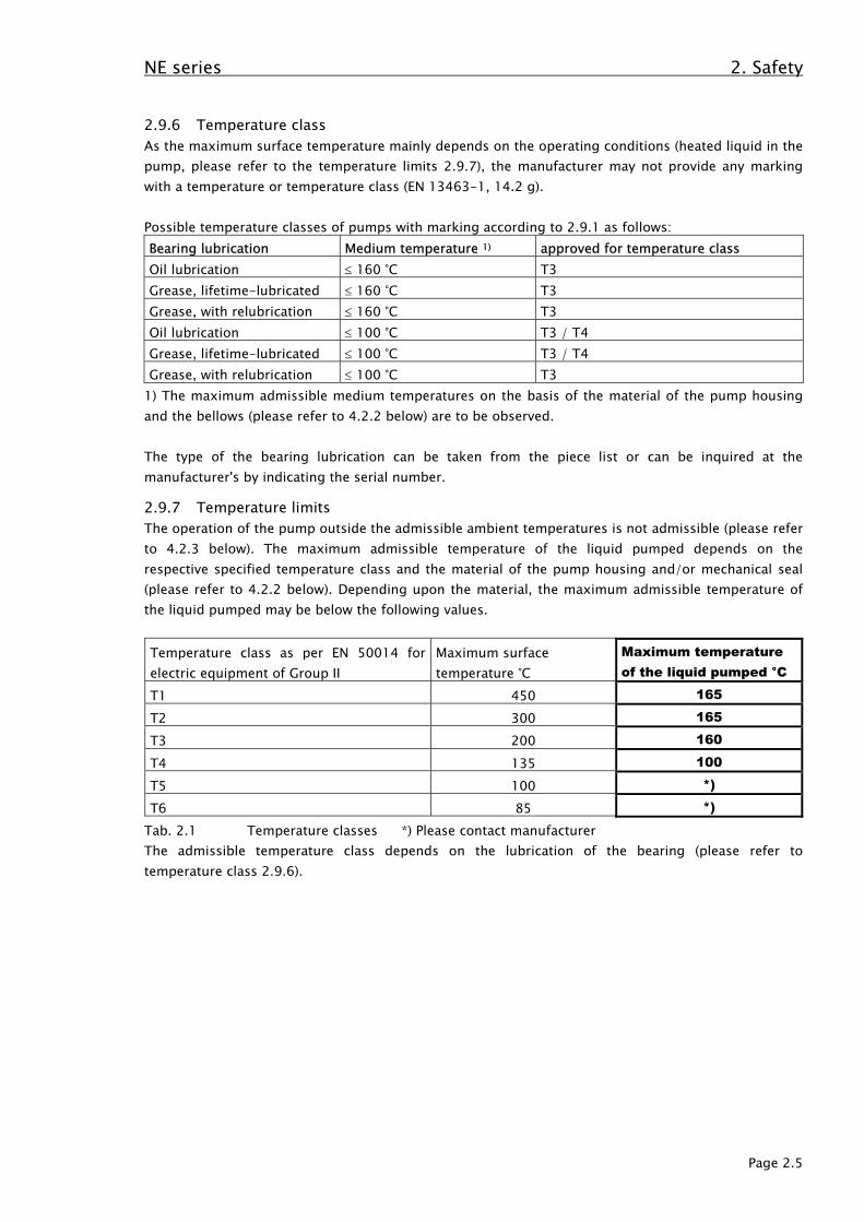
2.9.7 Temperature limitsThe operation of the pump outside the admissible ambient temperatures is not admissible (please referto 4.2.3 below). The maximum admissible temperature of the liquid pumped depends on therespective specified temperature class and the material of the pump housing and/or mechanical seal(please refer to 4.2.2 below). Depending upon the material, the maximum admissible temperature ofthe liquid pumped may be below the following values.
Temperature class as per EN 50014 forelectric equipment of Group II
Maximum surfacetemperature °C
Maximum temperatureof the liquid pumped °C
T1 450 165
T2 300 165
T3 200 160
T4 135 100
T5 100 *)
T6 85 *)
Tab. 2.1 Temperature classes *) Please contact manufacturerThe admissible temperature class depends on the lubrication of the bearing (please refer totemperature class 2.9.6).
NE series 2. Safety
Page 2.6
2.9.8 Pumping of inflammable mediaPumps by means of which inflammable media (Dangerous Goods Ordinance, Article 4 DangerousnessCharacteristics) are to be pumped must not be equipped with a single-acting mechanical seal unlessthe operator, due to suitable control systems, is in a position to assure that no danger can be broughtabout by the medium pumped. The manufacturer must be contacted. Here, the use of a double-actingmechanical seal is to be preferred. The required sealing pressure system must be designed andoperated with pressure, volume flow and temperature, if necessary, according to the requirements ofthe mechanical seal. The specification of the sealing medium and the operating instructions for thesealing pressure system must be complied with.
Note: Lubricants and/or coolants which are required to avoid explosive hot surfaces (here: mediumpumped or sealing medium to cool and lubricate the mechanical seal) or mechanical sparks (pleaserefer to prEN 13463-8) must have an ignition temperature (please refer to IEC 60079-4) of at least50 K above the maximum surface temperature of the equipment in which the liquid is used(prEN 13463-5).
2.9.9 MaintenanceOnly a pump or aggregate appropriately maintained and kept in a technically proper condition assuresa safe and reliable operation. The relubrication and exchange intervals (please refer to 7.1 below) ofthe bearing must be observed by all means. The lubrication being insufficient or the bearings
defective, there is a danger of the maximum admissible surface temperature beingexceeded and even of sparking through friction.According to the environmental conditions, the bearing bracket must be cleaned at suitable
intervals. Proper functioning of the mechanical seal and the supply of the additional connections(please refer to 5.4 and 7.2 below) must be assured by the user through regular controls.
NE Series 3. Transport and intermediate storage
Page 3.1
3. Transport and intermediate storage
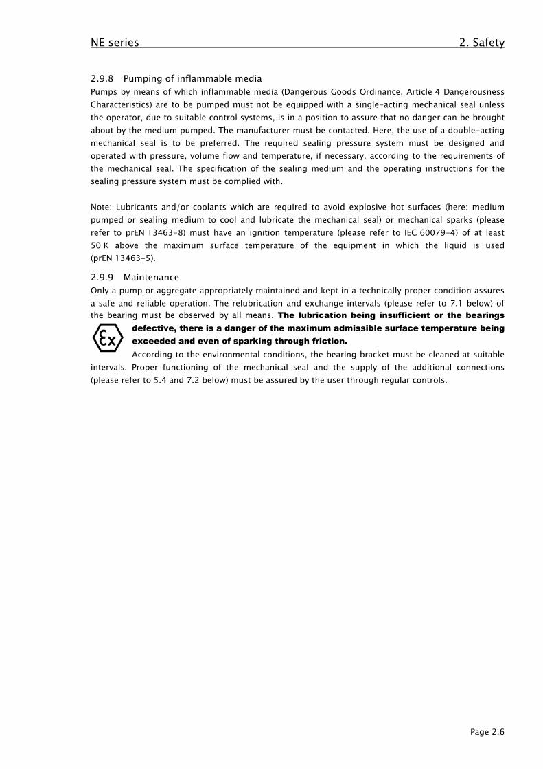
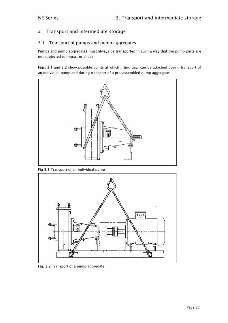
3.1 Transport of pumps and pump aggregates
Pumps and pump aggregates must always be transported in such a way that the pump parts arenot subjected to impact or shock.
Figs. 3.1 and 3.2 show possible points at which lifting gear can be attached during transport ofan individual pump and during transport of a pre-assembled pump aggregate.
Fig 3.1 Transport of an individual pump
Fig. 3.2 Transport of a pump aggregate

NE Series 3. Transport and intermediate storage
Page 3.2
3.2 Intermediate storage under normal environmental conditions
Under normal environmental conditions, i.e. within a temperature range of –10 °C to +40 °C,special provisions need not be made for an intermediate storage. By closing the pump openingswith sealing caps or dummy flanges, it must be assured that pollutions or foreign bodies inlumps are prevented from getting into the pump housing. The pumps must be placed in anintermediate storage so as not to be exposed to any shock or impact stresses. If this cannot beexcluded, the pumps should be protected by means of solid wooden packings. The pumpsshould likewise not be exposed to any extraordinary weather and environmental influences.
Plastic pumps need not be filled with liquid preservatives. Acid or lye residues must not remainin the pumps as these crystallize out and lead to damages to the mechanical seal. Water mustlikewise not remain in the machines. Danger of freezing up.
3.3 Intermediate storage under special environmental conditions
Particular environmental conditions are as follows:- Ambient temperatures below –10 °C or above +40 °C.- Intermediate storage or installation in the open.- Particularly high or very low air humidity (e.g. tropical or desert atmosphere).- Intermediate storage in an environment with corrosive parts in the atmosphere
(e.g. sea air or corrosive gases and aerosols)
The following are to be provided as protective measures:- Special protection by solid wooden packing against impact and shock influences.- Storage in areas not directly exposed to atmospheric influences. If necessary, provide
protective roofs.- Separate packing of the pumps with protective films and use of moisture binding agents.- Anti-corrosive coatings of uncovered metallic parts exposed to the atmosphere.- Sealing of the suction and delivery-side pump openings.
In each individual case, please contact the manufacturer for any measures to be taken regardingan intermediate storage under special environmental conditions.
3.4 Longer-term storage
In case of storage periods of more than one year make sure that the protection againstmechanical and climatic stresses is sufficient. The suction and delivery-side pump openingsmust be kept closed The condition of the packing (wooden box, packing film and the like) mustbe checked regularly, at least once a year, and repaired as required. When using moisture-binding agents, these must be exchanged at least once a year. Uncovered pump componentssuch as shaft and coupling must be provided with an anti-corrosive paint.Prior to starting any pumps which have been stored for an extended period of time, thecondition of the bearing grease or oil must be checked. After a storage period of two years, thelubricant of the bearing must be generally exchanged.Under climatic conditions of a low humidity, the elastic properties of bellows and sealingelements of elastomer materials such as FPM or CSM may be reduced. The replacement of theseparts after several years of storage is then required.

NE Series 3. Transport and intermediate storage
Page 3.3
If the pump remains out of operation for a minimum period of six months, the pump shaft mustbe turned into a different position every three months by several manual rotations so as to avoidany pressure marks on the rolling bearings.The mechanical seal has to be checked after two years.

NE series 4. Description of product and accessories
Page 4.1
4. Description of product and accessories
4.1 General description
Pumps of the NE series are horizontal rotatory pumps as defined by standards ISO 2858/ DIN EN22858 (chemical pump standards) using the process design. This makes it possible to quicklyremove or exchange the complete bearing support with running gear and shaft gasket withouthaving to disassemble the pipeline connections and the motor.The parts which will be covered with liquid are made of plastic materials or other suitablematerials, the respective chemical, thermal and mechanical stresses were decisive in theirselection. All statical parts made of plastic materials have been surrounded in metal or aresupported by metal.The standard version is equipped with a semi-open impeller (without covering disc), the specialversion can also be equipped with a closed impeller (with covering disc). The standard version ofsize IV is equipped with a closed impeller. The axial thrust for semi-open impellers will bereduced by back-vanes and for closed impellers by sealing elements. Usually a WERNERT-bellows-mechanical seal is used as a shaft seal. For special applications, mechanical seals byother manufacturers can also be used.
4.2 Application limits
4.2.1 Maximum permissible testing pressureStatic pressure is determined according to ISO 2858/ DIN EN 22858 as 1.3 to 1.5 times themaximum delivery pressure, and can be used up to the temperature stated in section 4.2.2. Theadmissible testing pressure depends on the version of the mechanical seal, in this case, themanufacturer should be consulted.
4.2.2 Maximum admissible temperature of the liquid pumpedThe maximum admissible temperature of the liquid pumped depends on the materials of thepump housing and bellows (for WERNERT bellows-type mechanical seal). In exceptional cases, itmay be exceeded on consultation with the manufacturer.
The maximum admissible temperature of the liquid pumped also depends onthe approved temperature class (please refer to 2.9.6 and 2.9.7 above).
Pump housingmaterial
Maximumtemperature
UHMW-PE 90 °CPVDF 115 °CPP 95 °CPTFE 165 °CPFA 165 °CWernit® 125 °CDurapox® 125 °C
For the employment of other mechanical seals, the corresponding data in the order confirmationand data sheet are decisive.
4.2.3 Admissible temperature range of the environmentThe admissible range of the ambient temperature is –10 °C to +40 °C. The name plate for apump according to EC Council Directive 94/9 receives the symbol "X" as additional marking forthe limited ambient temperature.
For WERNERT bellows-type mechanicalseal only:Bellowsmaterial
Maximumtemperature
CSM 80 °CFPM 100 °CPTFE 115 °C

NE series 4. Description of product and accessories
Page 4.2
4.2.4 Volume flow of the liquid pumpedUnless specified otherwise in the characteristic curves or the documentation, the following shallapply:Qmin = 0.1 x Qopt for short-time operation (approx. 5 min.)Qmin = 0.15 x Qopt for continuous operation, Qmax = according to characteristic diagramQopt = Volume flow in the optimum efficiency of the characteristic pump curveIn case of a deviating working point, please contact the manufacturer.
4.2.5 Maximum admissible gas portion of the liquid pumpedGas portions in the liquid pumped are only permissible after consulting the manufacturer. Gasportions in the liquid pumped reduce the capacity and the delivery head of the pump.
4.2.6 Maximum dimensions of sporadic solid matters in the liquid pumpedThe dimensions of sporadic solid matters in the liquid pumped must not exceed the dimensionof half the blade height and/or half the nominal delivery branch diameter, whatever dimension issmaller.
4.2.7 Maximum admissible supply pressure for WERNERT bellows-type mechanicalseal
The maximum admissible excess pressure at the suction branch of the pump with a WERNERTbellows-type mechanical seal depends on the material of the bellows and the speed of thepump.
Bellows material Speed up to 1800 1/min Speed over 1800 1/minCSM 2,5 bar 2 barFPM 2,5 bar 2 barPTFE 3 bar 2,5 bar
4.2.8 Maximum speedsThe maximum admissible speed must not be exceeded by mechanical transmission ratios or theemployment of a frequency converter. For the maximum admissible speed for the respectivepump size, please refer to Table B.2 of Annex B.

NE series 4. Description of product and accessories
Page 4.3
4.3 Construction
Fig 4.1 shows a pump of the NE series in section, which is representative for all sizes. Thenaming of the individual parts and the numbering comply with DIN 24250.
4.3.1 Pump casingThe solid pump casing is made of plastic material (part 101) and is completely enclosed by ametal annular casing (part 103). Suction and discharge nozzle are fixed to this pump casing. Thesuction nozzle is supported by a two part retaining ring (part 506.2), the discharge nozzle issupported by the casing part (part 130) and therefore fixed into the annular casing.The pump can be designed with an outlet in the area underneath the suction nozzle. This iseither closed with a cap or equipped with a valve.
4.3.2 ImpellerSemi-open wheels are used as impellers (part 233). Semi-open impellers are also suitable fortransporting media containing solids. The material used is solid plastic. The torque of the shaftis taken up by a metal hub pressed into the impeller. The impeller is fixed on the shaft in anaxial direction by the multiple ring (part 501). Closed impellers can also be used in special cases.Closed impellers are used on standard designed pumps size IV.
4.3.3 Shaft and bearingIn general, the impeller is connected with the metal shaft (part 210) via a thread. In the sealedarea, the shaft is protected by a shaft wearing sleeve (part 524) which is either made of carbonor a ceramic material. This shaft wearing sleeve is tensioned with the rotating seal ring(part 475) via a spanner (part 552.2) which is situated between thrower (part 507) and loosecollar (part 505). The shaft's torque is taken up by a feather key connection. The shaft issupported outside the transport area in the bearing housing (part 350). The rolling bearing canconsist of grease or oil lubrication and is protected by a bearing cover and bearing end cover(parts 360 and 361) with inserted shaft seal rings (parts 420). As standard version we haveinstalled life-time ball bearings. If requested the pumps can also be provided with bearings forregreasing. Additional grease is added via the grease nipples (parts 636). Oil lubrication isinstalled upon customer request, or if the temperature of the medium to be pumped is greaterthan 100°C. As standard version we use an oil level sight glass (part 642) for level monitoring.Alternatively the oil level can be regulated by means of a constant level oiler which will bemounted at the side of the bearing housing (part 350).
4.3.4 Sealing the pumpThe shaft is sealed using a mechanical seal (MS). Depending on the application, a number ofseals are used. These are described in more detail in section 4.5. The mechanical seal is takenup in every case by the seal insert (part 443) which also seals the pump casing via the O-ring(part 412.04). Discharge and suction nozzles are also sealed using O-rings (parts 412.01 and412.03). Gaskets are used in the “WERNIT” version. Additional static seals are installed in thearea of the mechanical seal and depend on its design. Usually FPM is used for the O-rings.

NE series 4. Description of product and accessories
Page 4.4
4.4 Sectional drawing
Part No. Description Part No. Description101 Pump casing 443 Seal insert103 Annular casing 463 Drip plate130 Casing part 472 Stationary seal ring145 Adapter 475 Rotating seal ring183 Support foot 481 Bellows210 Shaft 482 Bellows seat233 Counter clockwise impeller 501 Multiple ring321 Radial ball bearing 505 Loose collar350 Bearing housing 506.1 Retaining ring (seal insert)360 Bearing cover 506.2 Retaining ring (suction nozzle)361 Bearing end cover 507 Thrower412.01 O-Ring 511 Centering ring412.03 O-Ring 524 Shaft wearing sleeve412.04 O-Ring 552.2 Spanner (shaft wearing sleeve)412.05 O-Ring 683 Cap412.06 O-Ring 921 Shaft nut412.36 O-Ring 931 Lockwasher420.1 Shaft seal ring 932 Circlip420.3 Shaft seal ring 940 KeyFig. 4.1 Section of a pump of the NE series with single WERNERT-elastomere-bellows mechanicalseal.
NE series 4. Description of product and accessories
Page 4.5
ATTENTION
4.5 Designs of mechanical seals
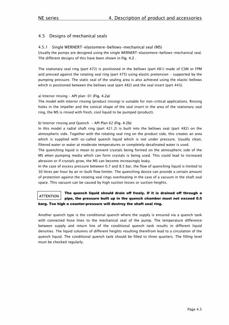
4.5.1 Single WERNERT-elastomere-bellows-mechanical seal (MS)Usually the pumps are designed using the single WERNERT-elastomere-bellows-mechanical seal.The different designs of this have been shown in Fig. 4.2 .
The stationary seal ring (part 472) is positioned in the bellows (part 481) made of CSM or FPMand pressed against the rotating seal ring (part 475) using elastic pretension - supported by thepumping pressure. The static seal of the sealing area is also achieved using the elastic bellowswhich is positioned between the bellows seat (part 482) and the seal insert (part 443).
a) Interior rinsing - API plan 01 (Fig. 4.2a)The model with interior rinsing (product rinsing) is suitable for non-critical applications. Rinsingholes in the impeller and the conical shape of the seal insert in the area of the stationary sealring, the MS is rinsed with fresh, cool liquid to be pumped (product).
b) Interior rinsing and Quench - API Plan 62 (Fig. 4.2b)In this model a radial shaft ring (part 421.2) is built into the bellows seat (part 482) on theatmospheric side. Together with the rotating seal ring on the product side, this creates an areawhich is supplied with so-called quench liquid which is not under pressure. Usually clean,filtered water or water at moderate temperatures or completely desalinated water is used.The quenching liquid is mean to prevent crystals being formed on the atmospheric side of theMS when pumping media which can form crystals is being used. This could lead to increasedabrasion or if crystals grow, the MS can become increasingly leaky.In the case of excess pressure between 0.7 and 8.5 bar, the flow of quenching liquid is limited to30 litres per hour by an in-built flow limiter. The quenching device can provide a certain amountof protection against the rotating seal rings overheating in the case of a vacuum in the shaft sealspace. This vacuum can be caused by high suction losses or suction heights.
The quench liquid should drain off freely. If it is drained off through apipe, the pressure built up in the quench chamber must not exceed 0.5
barg. Too high a counter-pressure will destroy the shaft seal ring.
Another quench type is the conditional quench where the supply is ensured via a quench tankwith connected hose lines to the mechanical seal of the pump. The temperature differencebetween supply and return line of the conditional quench tank results in different liquiddensities. The liquid columns of different heights resulting therefrom lead to a circulation of thequench liquid. The conditional quench tank should be filled to three quarters. The filling levelmust be checked regularly.

NE series 4. Description of product and accessories
Page 4.6
Part No. Description Part No. Description
412.05 O-Ring 482 Bellows seat
412.06 O-Ring 501 Multiple ring
412.09 O-Ring 505 Loose collar
421.2 Radial shaft seal ring 507 Thrower
443 Seal insert 524 Shaft wearing sleeve472 Stationary seal ring 550 Disc
475 Rotating seal ring 552.2 spanner
481 Bellows 739 Hose couplingFig 4.2 Representation of single WERNERT-elastomere-bellows-mechanical seala) with interior rinsing ( product rinsing ) of mechanical seal ( API Plan 01 )b) with interior rinsing ( product rinsing ) and quench ( API Plan 62 )c) with rinsing connection and flow control (continuous rinsing) ( API Plan 32 )d) with rinsing connection without flow control for rinsing after use (stationary rinsing)
NE series 4. Description of product and accessories
Page 4.7
c) Continuous rinsing – API Plan 32 (Fig.4.2c)Pumps to pump polluted liquids can be equipped with a rinsing connection (continuous rinsing)in order to rinse the mechanical seal with clean liquid - usually water - and to keepcontaminants away. To limit the flow of rinsing liquid, the shaft sealing space is equipped with alabyrinth seal towards the inside of the pump.Depending on the size of the pump and the contamination of the liquid to be pumped, 40 to250 l/h are used for rinsing. The flushing quantity is indicated by the manufacturer in the orderconfirmation. For the recommended flushing quantities, please also refer to Annex D. If fortechnical reasons, the recommended flushing quantities must be deviated from, please contactthe manufacturer.The installation of a liquid quantity meter (rotameter) in the flushing liquid line is recommendedfor the correct quantity to be set. For the regulation of the flushing liquid flow, a valve must beinstalled. The pressure arising during regulation of the flushing quantity must be checked.
d) Rinsing after use (Fig. 4.2d)Rinsing after use is equivalent to continuous rinsing, the only difference being that there is nolabyrinth seal. Stationary rinsing is to be used in those cases where contaminated liquids are tobe pumped but where it is not possible to install the continuous flow of rinsing liquid due tosystem or process constraints. It is used to rinse the pump immediately after it has beenswitched off. Stationary rinsing is meant to prevent sedimentation and crystallisation processesin the interior of the pump - especially in the area of the mechanical seal, as during longerstanding periods the rotating seal ring and the stationary seal ring can stick together. Rinsingvolume is 40 l for a rinsing period of 5 minutes (minimum). Normal industrial water can be usedfor rinsing.
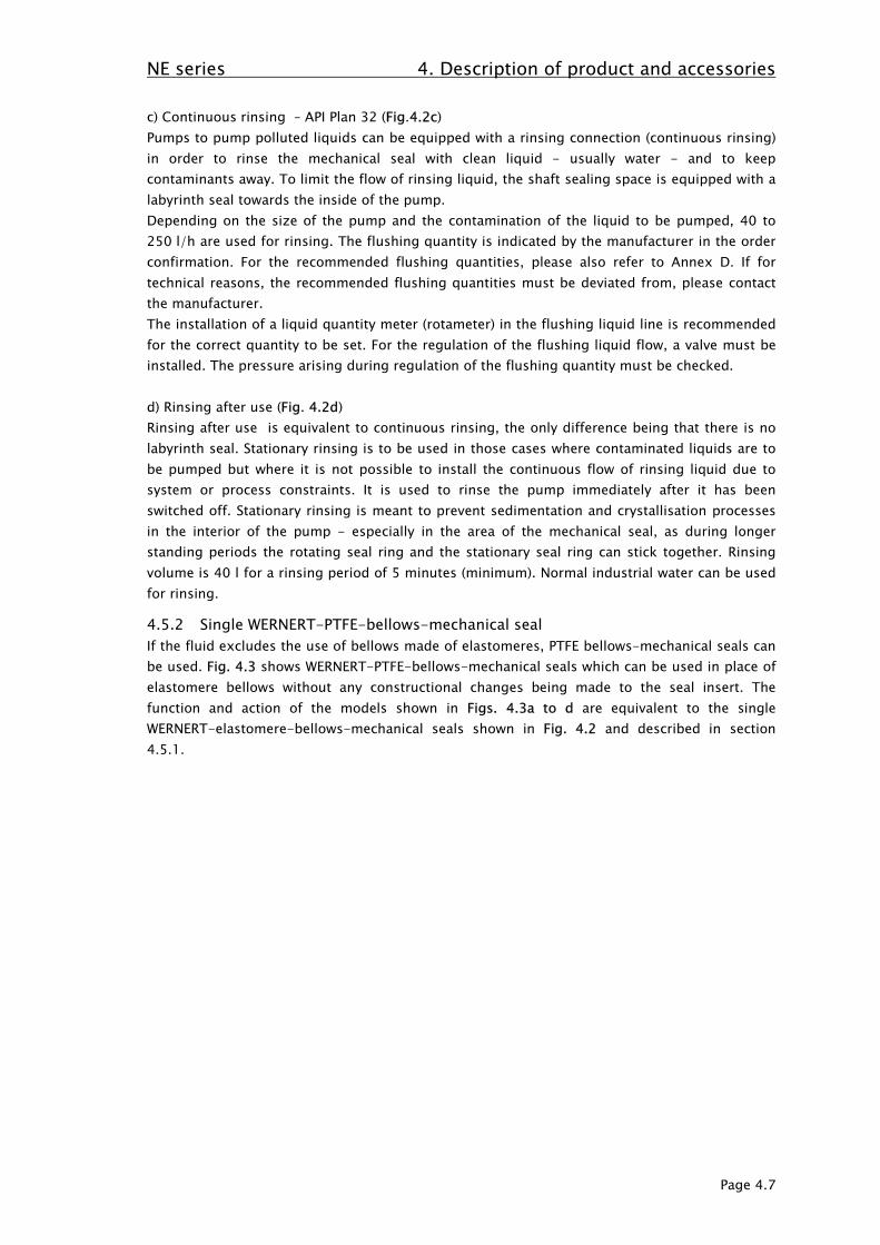
4.5.2 Single WERNERT-PTFE-bellows-mechanical sealIf the fluid excludes the use of bellows made of elastomeres, PTFE bellows-mechanical seals canbe used. Fig. 4.3 shows WERNERT-PTFE-bellows-mechanical seals which can be used in place ofelastomere bellows without any constructional changes being made to the seal insert. Thefunction and action of the models shown in Figs. 4.3a to d are equivalent to the singleWERNERT-elastomere-bellows-mechanical seals shown in Fig. 4.2 and described in section4.5.1.
NE series 4. Description of product and accessories
Page 4.8
Part no. Description Part no. Description
412.05 O-Ring 477 Spring for mechanical seal
412.06 O-Ring 481 Bellows
412.09 O-Ring 482 Bellows seat
412.22 O-Ring 501 Multiple ring
412.23 O-Ring 505 Loose collar
412.32 O-Ring 507 Thrower
421.2 Radial shaft seal 524 Shaft wearing sleeve
443 Seal insert 550 Disc
472 Stationary seal ring 552.2 spanner
474 Thrust ring 739 Hose coupling
475 Rotating seal ringFig 4.3 Representation of single WERNERT-PTFE-bellows-mechanical seala) with interior rinsing (product rinsing) of mechanical seal (API Plan 01)b) with interior rinsing (product rinsing) and quench (API Plan 62)c) with rinsing connection and flow control (continuous rinsing) (API Plan 32)d) with rinsing connection without flow control for rinsing after use (stationary rinsing)

NE series 4. Description of product and accessories
Page 4.9
4.5.3 Back-to-back-mechanical seals as defined by DIN EN 12756Back-to-back mechanical seals as defined by DIN EN 12756 (Fig. 4.4) are usually used for liquidto be pumped which have virtually no or only a small amount of solid material in them,- which endanger health, water or the environment- which would vaporise at a very small increase in temperature or if the pressure is decreased- which tend to crystallisation.
A single mechanical seal is installed back-to-back on the product side and atmospheric side.The so-called sealing chamber is situated between the two pairs of mechanical seals. Usually theseal rings on the product side are secured against inadmissible axial and radial movement.
For further information about double acting mechanical seals please refer to section 4.5.5.
Part No. Description Part No. Description412.05 O-Ring 505 Loose collar412.06 O-Ring 507 Thrower412.07 O-Ring 524.1 Shaft wearing sleeve412.08 O-Ring 524.2 Shaft wearing sleeve433 Mechanical seal 528 Locating collar443 Seal insert 543 Spacer bush476 Stationary seal holder 552.2 spanner501 Multiple ring 562.1 Parallel pinFig 4.4 Diagram of a back-to-back-mechanical seal as defined by DIN EN 12756 (API Plan 54),lower half with pump thread (API Plan 53).

NE series 4. Description of product and accessories
Page 4.10
4.5.4 Stationary double acting mechanical sealStationary double acting mechanical seals are usually used for "problematical” liquid to bepumped- which have a medium to high solid content- which contain a high proportion of gas or air- which endanger health, water or the environment- which would vaporise if the temperature increased only slightly or if the pressure was
reduced- which tend toward crystallisation.
This type of mechanical seal (frequently also referred to as REA design), supports, by means ofcentrifugal forces, the movement of the sealing liquid from the sealing chamber into the shaftsealing space which in turn is very large and easy to rinse. This design avoids tight gaps andsolids being deposited.
Two types are used as standard:BURGMANN HS HRZ 8, shown in Fig 4.5.PACIFIC Allpac N 2132, shown in Fig. 4.6.
These models are also available with single seals or single seals with quench.
For further information about double acting mechanical seals please refer to section 4.5.5.
4.5.5 General information about double acting mechanical sealsDouble acting mechanical seals must always be impinged with a suitable sealing fluid which issuited to be mixed with the liquid to be pumped. The sealing liquid can also - if the currentlyvalid regulations permit this - be the cleaned fluid which might have to be cooled, but which canonly be used if the metal elements within the sealing chamber do not corrode. The sealing liquidmust continuously circulate between the two mechanical seals and is removed via an outlet onthe opposite side. The sealing fluid must have a pressure of 1 to 1.5 bar above the pressure onthe shaft sealing space. However, it must not exceed the pressure limit of the seal on theatmospheric side.
The maximum pressure in the shaft sealing space, which is immediately behind the impeller, isapprox. 25% of the maximum differential pressure which can be achieved in the pump (withdecreasing pumping flow) plus the supply pressure (pressure at the pump suction nozzle). If thepump is not working, it must be ensured that the pressure of the sealing liquid is higher thanthe interior pressure of the pump so that no liquid to be pumped reaches the sealing chamber.
If the sealing chamber is equipped with its own sealing aggregate with limited sealing liquidvolume, the sealing liquid must be forcibly cooled and circulated. In this case the circulation ofthe sealing liquid flow is supported by a pumping thread in the mechanical seal.
If the sealing chamber is supplied with sealing liquid with the appropriate excess pressure and ifthe sealing liquid can flow freely from the sealing chamber, the liquid flowing off must bethrottled in order to maintain the excess pressure in the sealing chamber.

NE series 4. Description of product and accessories
Page 4.11
Parts No. Description Parts no. Description
412.05 O-Ring 501 Multiple ring
412.06 O-Ring 505 Loose collar
412.12 O-Ring 507 Thrower
412.30 O-Ring 524 Shaft wearing sleeve
433 Mechanical seal 552.2 spanner
443 Seal insert 562.1 Parallel pin
476 Stationary seal ring holderFig 4.5 BURGMANN HS HRZ 8 (API Plan 54), lower half with pumping thread (API Plan 53).
NE series 4. Description of product and accessories
Page 4.12
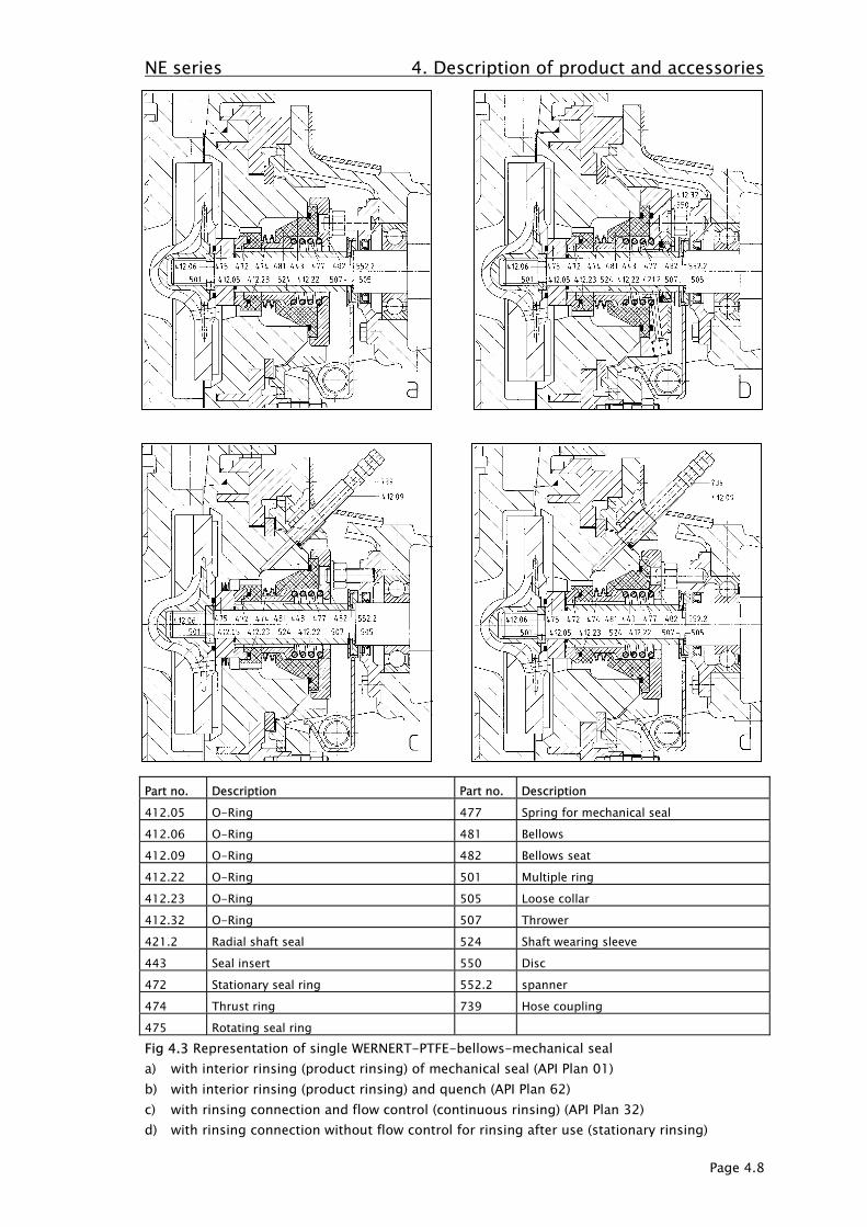
Part no. Description Part no. Description412.05 O-Ring 443 Seal insert412.06 O-Ring 500 Ring412.08 O-Ring 501 Multiple ring412.12 O-Ring 505 Loose collar412.30 O-Ring 507 Thrower433 Mechanical seal 524 Shaft wearing sleeve441 Housing for shaft seal 552.2 spannerFig 4.6 PACIFIC Allpac N 2132 (API Plan 54), lower half with pumping thread (API Plan 53).

NE series 4. Description of product and accessories
Page 4.13
4.6 Special tools
The special tools described below are available from the manufacturer.
4.6.1 Impeller key (Part 051)Only for bearing support sizes 0 - III:To disassemble and assemble semi-open impellers with screw attachment onto the drive shaft itis wise to use a so-called impeller key (Fig. 4.7). The inside of this key is shaped to be a negativeof the impeller blades. The key is placed on the facing side of the impeller which is thenremoved from the shaft in the direction of rotation of the pump. The shaft must be fixed inorder to prevent it turning too.
Fig. 4.7 impeller key (part 051)
4.6.2 Tensioning tools (Part 052)Only for bearing support sizes I - III:In order to be able to place the multiple ring (Part 501) with zero force behind the threaded stemof the shaft (part 210), the stationary seal ring and the shaft wearing sleeve must be displaced inthe direction of the coupling against the force of the face plate. This is done by using atensioning tool as shown in Fig. 4.8.
Fig. 4.8 Assembly of the multiple ring

NE series 4. Description of product and accessories
Page 4.14
4.7 Noise emission values
The A-weighted equivalent permanent sound level at a one meter (1 m) distance from thereference cuboid according to EN ISO 3744 is below 85 dB(A).
4.8 Accessories
- Coupling: Flexible coupling with or without intermediate coupling sleeve- Protection against accidental contact for coupling- Base plate of torsion-resistant design of grey cast iron- Foundation fastening and/or installation: Levelling elements, stone bolts, shear connectors- Special accessories, according to order
4.9 Dimensions and weights
For the data on dimensions and weights, please refer to the dimensional drawing and/orinstallation plan of the pump.
NE series 5. Erection
Page 5.1
5. Erection
5.1 General
A careful and proper installation is the prerequisite to a subsequent trouble-free operation.Installation errors may cause personal injuries and property damages as well as a premature wear ofthe pump. In case of work not done by the manufacturer, any liability for improper installation andfor the consequences of non-compliance with safety-technical hints is excluded.
The EC Council Directive 1999/92 on minimum regulations for the improvementof the health protection and safety of the employees who may be endangeredby explosive atmospheres must be complied with. The EN 1127-1 Standard is to
be observed (explosion protection).
5.2 Erection of pumps mounted on base plates
5.2.1 Aligning the base plateBefore delivery, the pump is aligned with the base plate and fixed. If, due to rough transport, theposition of the pump to the base plate has changed, then the original position must be attainedagain by referring to the plans.Otherwise, the pump is aligned to the plant merely by positioning the base plate.
When installing the plant, the base plates must be aligned so that1) the level of the discharge nozzle is horizontal in every direction. For example, this can be
checked with a machine spirit level.2) Suction and discharge pipelines must be connected with the pump nozzles in such a way that
the admissible nozzle loads are not exceeded. The admissible nozzle loads are listed inAppendix B.
The base plate is aligned according to the means of fixing selected for this aggregate. There arethree ways of fixing possible:1) Simple fixing to the foundations
The base plate is fixed to the foundations by means of stone bolts or shear connectors whichhave been anchored into the foundation beforehand and which project through thecorresponding holes in the base plate. Before these are tightened, the base plate must bealigned using spacers and thin pieces of metal.The base plate is aligned in such a way that it is supported by three aligning spacers. Eachspacer is positioned on the left and right longitudinal side in the area of the drive, the thirdspacer is positioned in the area of the pump on the short side. If the base plate is longer than1600 mm, more spacers might be necessary. The exact height should be achieved using piecesof thin metal of different thicknesses.
2) Fixing on foundations with subsequent castingThe base plate is fixed to the foundations by means of stone bolts or shear connectors whichhave been anchored into the foundation beforehand and which project through thecorresponding holes in the base plate. Before casting, the base plate must be aligned usingspacers and thin pieces of metal (as described in 1.). The foundation screws are tightened oncethe casting mass has hardened.
3) Erection on levelling elements without foundationThe position of the base plate is adjusted using levelling elements. The pump aggregate issupported above the floor on oscillation absorbers. No foundation screws are necessary.
NE series 5. Erection
Page 5.2
ATTENTION
The above three types of fixing are suitable for all pumps of the NE series supplied on base plates.
Pumps of Type NE supplied on base plates are in principle suited for all three fastening typesmentioned above. If the pump aggregate is installed, isolated, as is the case,for example, with the foundation-free installation, a separate earthing is to beprovided in order to avoid potential differences.
5.2.2 Connecting the pipesBefore aligning the drive, the pump must be connected to the pipes making sure that the pipes donot twist the pump. The admissible nozzle loads listed in Appendix B must not be exceeded!Section 5.3 lists suggestions on the design of the pipeline layout.If subsidiary pipeline connections have been intended, e.g. for sealing, rinsing or quench media, thenecessary pipeline attachments and connections must be made.
5.2.3 Aligning the driveThe manufacturer's alignment of the drive to the pump must be checkedunder all circumstances and if necessary it must be corrected. Please
refer to the operating instructions for the coupling.
The position of the drive shaft to the pump shaft is measured via the coupling.
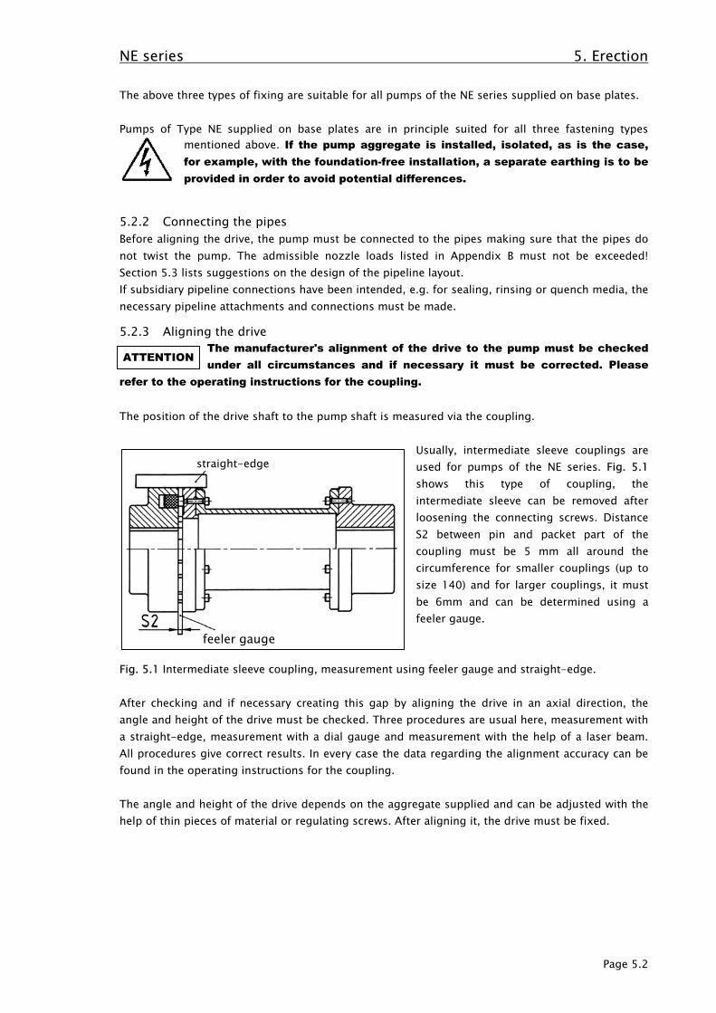
Usually, intermediate sleeve couplings areused for pumps of the NE series. Fig. 5.1shows this type of coupling, theintermediate sleeve can be removed afterloosening the connecting screws. DistanceS2 between pin and packet part of thecoupling must be 5 mm all around thecircumference for smaller couplings (up tosize 140) and for larger couplings, it mustbe 6mm and can be determined using afeeler gauge.
Fig. 5.1 Intermediate sleeve coupling, measurement using feeler gauge and straight-edge.
After checking and if necessary creating this gap by aligning the drive in an axial direction, theangle and height of the drive must be checked. Three procedures are usual here, measurement witha straight-edge, measurement with a dial gauge and measurement with the help of a laser beam.All procedures give correct results. In every case the data regarding the alignment accuracy can befound in the operating instructions for the coupling.
The angle and height of the drive depends on the aggregate supplied and can be adjusted with thehelp of thin pieces of material or regulating screws. After aligning it, the drive must be fixed.
straight-edge
feeler gauge

NE series 5. Erection
Page 5.3
ATTENTION
5.3 Pipes
5.3.1 GeneralThe pipe diameter and the layout of the pipes has usually been determined during the planningstage. The recommendations for pipeline layout can only be basic considering that the final layingof the pipes will have to take the specific local situation, which the pump manufacturer is usuallynot aware of, into consideration.
5.3.2 Notes on laying pipesMake sure that the forces and moments of the pipelines acting on the pump branches do notexceed the admissible branch loads according to Annex B. This applies to both, the standstill of theplant and its operation. The pumps must in particular not serve as a fixed support within thepipeline system. If necessary, the pipelines must be supported by mounts so that they can neitherdistort the pump nor vibrate it during operation.Any expansions of the pipelines caused by temperature differences and process-conditionedimpacts must be compensated for by taking suitable measures. The installation of compensators infront of the suction and delivery branches of the pump is recommended. For any increased flowresistances to be avoided, compensators should have the nominal diameter of the respective
pipeline. The pipeline forces being exceeded, leaks may be caused at the pumpresulting in the penetration of the medium pumped. Danger of life in case oftoxic or hot media pumped. Inadmissible deformations may furthermore resultin problems at the mechanical seal.
Tightening connection screws on the pump flanges may not cause any twisting. Up to and includingDN 125, the torque should be approx. 35 Nm and above that up to and including DN 250, approx.70 Nm for each screw.
When laying and connecting the pipes care must be taken that seals do not project into the cleardiameter. Fig. 5.2 shows the correct arrangement on the left hand side and the incorrectarrangement on the right hand side.
correct incorrectFig. 5.2 Connection of pipelines
The alignment of the drive to the pump must be checked, and if necessarycorrected, after the pipes have been connected and before starting up.
NE series 5. Erection
Page 5.4
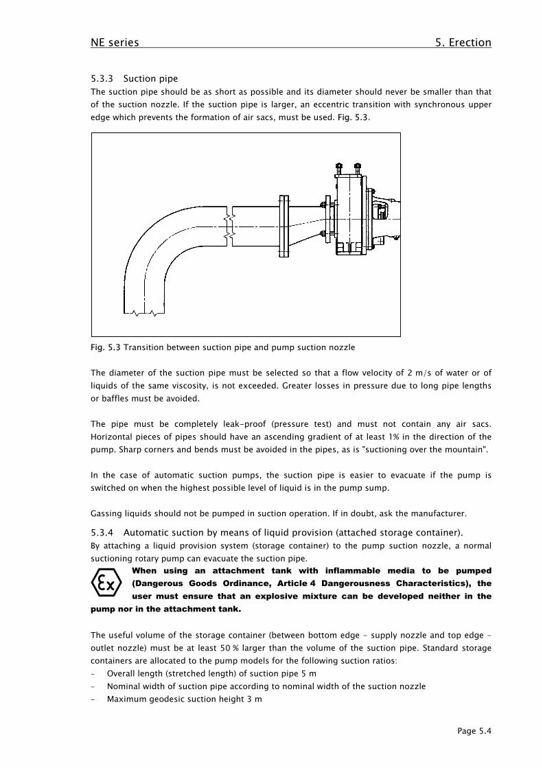
5.3.3 Suction pipeThe suction pipe should be as short as possible and its diameter should never be smaller than thatof the suction nozzle. If the suction pipe is larger, an eccentric transition with synchronous upperedge which prevents the formation of air sacs, must be used. Fig. 5.3.
Fig. 5.3 Transition between suction pipe and pump suction nozzle
The diameter of the suction pipe must be selected so that a flow velocity of 2 m/s of water or ofliquids of the same viscosity, is not exceeded. Greater losses in pressure due to long pipe lengthsor baffles must be avoided.
The pipe must be completely leak-proof (pressure test) and must not contain any air sacs.Horizontal pieces of pipes should have an ascending gradient of at least 1% in the direction of thepump. Sharp corners and bends must be avoided in the pipes, as is "suctioning over the mountain".
In the case of automatic suction pumps, the suction pipe is easier to evacuate if the pump isswitched on when the highest possible level of liquid is in the pump sump.
Gassing liquids should not be pumped in suction operation. If in doubt, ask the manufacturer.
5.3.4 Automatic suction by means of liquid provision (attached storage container).By attaching a liquid provision system (storage container) to the pump suction nozzle, a normalsuctioning rotary pump can evacuate the suction pipe.
When using an attachment tank with inflammable media to be pumped(Dangerous Goods Ordinance, Article 4 Dangerousness Characteristics), theuser must ensure that an explosive mixture can be developed neither in the
pump nor in the attachment tank.
The useful volume of the storage container (between bottom edge - supply nozzle and top edge -outlet nozzle) must be at least 50 % larger than the volume of the suction pipe. Standard storagecontainers are allocated to the pump models for the following suction ratios:- Overall length (stretched length) of suction pipe 5 m- Nominal width of suction pipe according to nominal width of the suction nozzle- Maximum geodesic suction height 3 m
NE series 5. Erection
Page 5.5
ATTENTION
If the volume of the suction pipe and / or the geodesic suction height is larger than the abovefigures, the storage containers must be adapted to suit the suction conditions.
When suctioning via the storage container, the pump should be equipped with a reflux valve (referto 5.3.7 below) on the discharge side in order to avoid the pump and container emptying by siphoneffect once the pump has been switched off.
Prior to initial start-up or after draining, the attachment tank must be filled up with liquid at thefilling opening. Thereafter, the filling opening must be closed, gas-tight. In addition, it must beassured that the suction line is sufficiently vacuum-resistant.
Pipes which are to be connected to the attached storage container must be secured without tension.They must be supported by brackets or retainers. The pipes must not apply any forces or momentsto the container and connectors. The attached storage container must be connected as close to thepump as possible. If possible, pump and attached storage container should be mounted on acommon base plate. If the attached storage container is not placed on the base plate, care must betaken to ensure that the bottom of the attached storage container rests fully on a level surface andis properly secured.
5.3.5 Supply lineThe supply line is to be laid with a constant inclination towards the pump suction branch andshould never be smaller than the suction branch of the pump. The cross section of the supply linemust be selected so that a flow speed of 2.5 m/s in case of water or liquids of the same viscosity isnot exceeded.
For repair purposes, the installation of a shut-off valve at a sufficient distance to the suction branch(approx. 2 to 3 times the pipeline diameter) is recommended which must be completely openedduring the operation of the pump. The shut-off devices in the supply and/or suction line are to bearranged so that according to the valve design, no air pockets may be formed. The control of theflow rate may only be effected by control instruments in the discharge line.
To avoid increased flow resistances, additional instruments which must be installed should have thenominal diameter of the supply line. Sharp edges and bends are to be avoided.
5.3.6 Discharge line, throttling bushThe discharge line should not be smaller than the delivery branch of the pump. In addition, thediameter depends on economic aspects, however, the flow velocity should not be selected above5 m/s. A shut-off and/or control instrument is to be installed as close as possible to the pump.
Pumps whose type designation bears the supplementary letter "D" (e.g. NEPO 80-50-315 D) aredesigned with a smaller cross section in the delivery branch. The working point of this pump has
been designed with a throttling bush, therefore, the pump must be operated withthe same. In case of changes to the cross-sectional area of the throttling
bush, considerable damages to the pump must be expected.
5.3.7 Return flow preventerA return flow preventer must be arranged above the delivery branch of the pump so that duringcommissioning, the pump is safely filled with the medium pumped even if an air cushion is formedin front of the return flow preventer.

NE series 5. Erection
Page 5.6
ATTENTION
5.4 Additional connections
For the dimensions and position of the additional connections required for the pump (sealing liquid,flushing liquid etc.), please refer to the installation plan.
These connections are decisive for the function and must therefore beproperly attached. The required volume flows and pressures are to be set
(please refer to 7.2 below).
5.5 Coupling protection
The pump may only be operated with a suitable coupling protection. Due to its strength, distance tothe coupling and material, a coupling protection contained in the scope of supply of an aggregatecorresponds to the employment in a potentially explosive atmosphere.
5.6 Final inspection and testing
The alignment according to Item 5.2 above as well as the proper distance of coupling and couplingprotection are to be checked. At the coupling, the shaft must be capable of being turned by hand.
5.7 Electric connection
The electric connection may only be made by an electrical expert. Thesuitability of the motor for the available mains voltage is to be checked againstthe data on the name plate. A suitable circuit is to be selected. Theemployment of a protective motor device is recommended. In potentiallyexplosive atmospheres, DIN EN 60079-14 must be observed.
NE series 6. Starting up / Operation / Shutting down
Seite 6.1
ATTENTION
ATTENTION
ATTENTION
ATTENTION
ATTENTION
6. Starting up / Operation / Shutting down
6.1 Measures to be taken before starting up
6.1.1 Cleaning and hydraulic pressure test of pipesBefore starting the pump up for the first time, all foreign bodies which might be left in the pipesfrom the installation of the pump, must be removed (screws, forging scales, welding drops etc.).Then the pipes are checked for leaks. Suction and discharge pipes must be hydraulically testedin accordance with the respective safety instructions.Before starting up the pump again after repairs have been made to the pump, all broken parts ofany kind - especially duroplastic or ceramic parts - must be removed from the pipelines. Thesebroken parts can be caused when the mechanical seal is broken or if components made ofDurapox® or Wernit® break suddenly due to overload or the action of foreign bodies.
Broken parts or foreign bodies remaining in the pipeline system cancause disastrous damage to the pump or other parts of the plant.
6.1.2 Ensure bearing lubricationa) Bearings lubricated with greaseBearings are lubricated with suitable grease before delivery.
It is not necessary to re-lubricate before starting up, in fact this couldcause damage as too much lubrication can cause the bearings to
overheat.
b) Oil-lubricated bearingsBefore starting up the system, the bearing housing must be filled with oil!Filling with oil is effected as described in Section 7.1.2 below.
Operation of the pump with insufficient lubrication of the bearings leads tothe maximum admissible temperature of the surface being exceededthrough to sparking caused by friction.
6.1.3 Checking the direction of rotationPump aggregates with intermediate sleeves are supplied in an uncoupled state. To do this, thecam plate of the coupling is unscrewed, but still projects into the packet part of the coupling.The screws are on the inside of the intermediate sleeve which must be removed before thedirection of rotation is checked.
Pump aggregates without intermediate sleeves are - if possible - also supplied in an uncoupledstate.
Only check that the direction of rotation of the motor is identical to thedirection of rotation of the pump in an uncoupled state.Please ensure that the motor has been cut off from the electricity supply
when the intermediate sleeve is being removed and re-installed.
Each pump has been given an arrow to indicate the direction of rotation on the top of thebearing housing (part 350) by the factory.
Even if the motor runs in the wrong direction for only a short time, thepump can be damaged!
NE series 6. Starting up / Operation / Shutting down
Seite 6.2
ATTENTION
ATTENTION
ATTENTION
6.1.4 Tightening the WERNERT-elastomere-bellowsThe serial shaft seal is a patented WERNERT bellows-type mechanical seal with the bellows madeof elastomer (CSM or FPM). The bellows seat (Part 482) acc. to Figure 7.5.2 is to be tightenedonly to such a degree that the space between bellows and neck of the sealing insert is sealed. Atorque of approx. 7.5 Nm is specified as reference value. With the WERNERT PTFE bellows, thetightening torque is approx. 15 Nm. By means of screws (Part 901.76), the hoods removed
(Part 683) are to be fixed again to the bearing block. During cleaning or mountingthe hoods or mounting the hoods see to it that there is no static discharge.A non-conducting material may be charged by friction. This must be avoided.
If leaks occur due to advanced wear of the seal rings, the bellows seat should not be tightened.If a different shaft seal design has been intended, tightening is not possible anyway.
ONLY FOR WERNERT-ELASTOMERE-BELLOWS:The pump is supplied with a relaxed elastomere bellows so that the
pre-tension due to longer periods of storage are not decreased. For this reason theelastomere bellows must be pretensioned before starting up by tightening the bellowsseat.
6.1.5 Safety devices for the protection of people
Please ensure that before starting up, rotating parts of the pump are notfreely accessible.
Make sure that the protective device to prevent machinery being touched, must be attachedabove the coupling, Fig. 7.3, as must the spray protection on the bearing housing, Fig. 7.55. Ifthe pump is driven using belts, all respective safety devices must be fixed above the discs andthe belts.Electrical motors and other devices must be installed in accordance with the currently validsafety regulations (refer to 5.6).
6.2 Starting up the pump
When starting up the pump, please follow the following procedures:1) If a flushing or sealing liquid supply is provided, same must first be started with the
required pressure and volume flow (refer to 7.2).2) The supply and suction line as well as the pump body must be filled with liquid. A complete
ventilation of the pump body sufficient in time must be ensured.
The pump must not run dry.
3.) Valves on the suction side must be completely opened. Delivery-side shut-off valves shouldpreferably be slightly opened so that the pump is not operated against a closed valve, i.e.operation at zero delivery. However, if due to the plant conditions, the pump must bestarted against closed shut-off valves, this may result in an inadmissible heating of thepump.
The pump may be operated against a closed shut-off valveonly during starting and only for one minute at the most.
The manufacturer's consent is required if it is to be operated with closed shut-downfittings for longer periods of time. The pump may be started against a closed non-return-flap.
4.) The drive is started up.5.) Regulators on the discharge side must be opened so far so that nominal flow is achieved.

NE series 6. Starting up / Operation / Shutting down
Seite 6.3
ATTENTION
If during operation it is expected that the shut-down fittings on the discharge side will be closeddown, then a bypass must be installed in front of these and returned to the pump container (notto the suction nozzle!). This is the only way in which overheating of the pump can be avoided.If the pump is being switched continuously (i.e. more than 3 switching on processes per hour) anauxiliary start-up device should be installed (star- triangle-switch, electronic smooth start updevice, hydraulic clutch or similar) in order to reduce mechanical strain. The use of this type ofdevice depends on the utilisation factor of the machine (coupling performance, speed, switchingfrequency) and should be discussed with the manufacturer.
6.3 Operating the pump
During operation see to it that due to changes no inadmissible operating conditions may occur.These are in particular:- Delivery-side modifications, for example by opening or closing valves. In this connection,
see to it that the required minimum volume flow (please refer to 4.2.4) is maintained. Inthis state, there is a danger that after a short time already, the mediumpumped takes inadmissible temperatures and the maximum admissibletemperature of the surface is exceeded.
- Suction-side modifications, for example by closing valves, pollution of filters, pipelines,valves or in the medium as such lead to the reduction of the supply pressure. The result
hereof may be insufficient lubrication or even dry running of the mechanical seal.Under these conditions, the maximum admissible temperature limit can beexceeded and the mechanical seal destroyed.
- The required pressure and volume flow at additional connections such as sealing, flushingliquid etc. must be ensured by the user (refer to 5.4 and 7.2). This applies in particular toquenching and sealing liquid. Here, a sufficient cooling and lubrication of the radial shaft
ring and/or mechanical seal must be ensured. Insufficient lubrication or dryoperation results in the maximum admissible surface temperature beingexceeded and in the destruction of the parts to be lubricated.
- When using attached tanks, it must be ensured by the user that the tank is alwayssufficiently filled. Here, there is also a danger of dry running.
- The bearing must be controlled and maintained (please refer to 7.1 below).- The application limits mentioned under Section 4.2 above are to be observed.
6.4 Switching the pump off for a short period of time
The following procedure is to be performed if the pump is to be switched off for a short periodof time:1) The shut-down fitting on the discharge side must be closed or reduced to minimum flow
(close completely after the motor has been stopped).2) The drive machine is switched off.
Flushing and sealing liquid supply must continue even after the drivemachine has been switched off.
3) If there is the danger of freezing, the liquid to be pumped must be removed from thepump.
6.5 Shutting the pump down permanently
The following steps must be carried out if the pump is to be shut down permanently:1) The shut-down fitting on the discharge side is to be closed or turned to minimum volume
(after the motor has been switched off, it must be closed completely).2) The drive is shut down.

NE series 6. Starting up / Operation / Shutting down
Seite 6.4
3) The entire plant systems, including the pump, must be relaxed and emptied.4) The rinsing and sealing liquid supply must be turned off.5) If the liquid to be pumped tends to crystallise, the pump must be rinsed with clean water.

NE series 7. Maintenance / Repairs
Seite 7.1
ATTENTION
7. Maintenance / Repairs
7.1 Monitoring and maintaining the shaft bearing
The pumps are equipped with rolling bearings. In case of continuous operation, the bearingtemperature may be approx. 60°C above the ambient temperature. If a pump isemployed in a potentially explosive atmosphere (refer to 2.9.1 above), thebearings must be exchanged after a maximum of 16.000 operating hours.Bearings must be regularly checked and/or controlled to avoid the risk of an
ignition. If the pump is not employed in a potentially explosiveatmosphere, the bearings must be checked and exchanged, if necessary,
after approx. 16.000 operating hours, at the latest, however, after three years.Insufficient lubrication may lead to an inadmissible temperature increase. Due to anexcessive wear, it leads to a reduction of the service life through to the destruction ofthe bearings. The limitation of the temperature class due to the kind of lubrication mustbe observed (please refer to 2.9.6 above).
7.1.1 Grease lubricationUnless otherwise specified, lifetime-lubricated bearings are provided. Regreasable bearings mayoptionally be selected.
7.1.1.1 Lifetime-lubricated bearingsThe lifetime-lubricated grooved ball bearings are serially designed with guard disks on both sides.The bearings sealed on both sides are lifetime-lubricated and maintenance-free. Therefore, prior toinstallation, they should by no means be heated to above 80°C or rinsed. The grooved ball bearingsare filled with standard lubricating greases. The lubricating grease has good anti-corrosiveproperties and contains lithium soap as thickener.
7.1.1.2 Grease lubrication with relubricationBearings lubricated using grease are filled with suitable grease at the manufacturer's. It is notnecessary to re-lubricate before starting up, in fact this would even be damaging as it can lead tothe bearing overheating.
New grease is applied in the spaces of the bearing cage. The grease chambers must only be onethird full of grease as too much grease causes the bearings to overheat. All known greasemanufacturers can supply suitable grease.
The greases which can be used have the following abbreviation according to DIN 51502:KP 2 K -30.
Attributes of the grease:Basicoil: Mineral oilSoap: Lithium-CalciumTemperature range: -30 bis 130 °CBasic oil viscosity at 40 °C: 100 mm²/s
Basic oil viscosity at 100 °C: 11 mm²/sCharacteristic value of RPM: 600.000 mm/minWorked penetration at 25 °C: 265-295Consistency class: 2
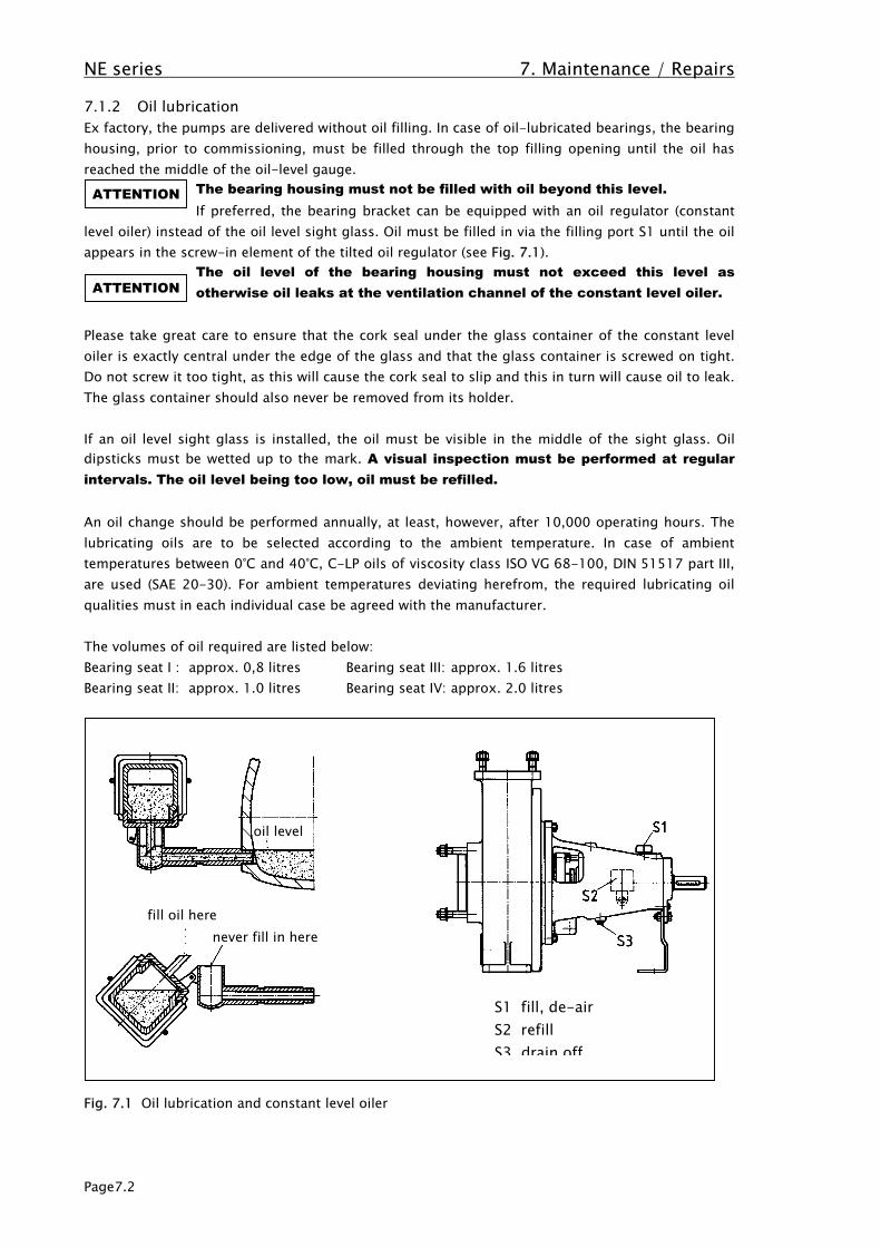
NE series 7. Maintenance / Repairs
Page7.2
ATTENTION
ATTENTION
7.1.2 Oil lubricationEx factory, the pumps are delivered without oil filling. In case of oil-lubricated bearings, the bearinghousing, prior to commissioning, must be filled through the top filling opening until the oil hasreached the middle of the oil-level gauge.
The bearing housing must not be filled with oil beyond this level.If preferred, the bearing bracket can be equipped with an oil regulator (constant
level oiler) instead of the oil level sight glass. Oil must be filled in via the filling port S1 until the oilappears in the screw-in element of the tilted oil regulator (see Fig. 7.1).
The oil level of the bearing housing must not exceed this level asotherwise oil leaks at the ventilation channel of the constant level oiler.
Please take great care to ensure that the cork seal under the glass container of the constant leveloiler is exactly central under the edge of the glass and that the glass container is screwed on tight.Do not screw it too tight, as this will cause the cork seal to slip and this in turn will cause oil to leak.The glass container should also never be removed from its holder.
If an oil level sight glass is installed, the oil must be visible in the middle of the sight glass. Oildipsticks must be wetted up to the mark. A visual inspection must be performed at regularintervals. The oil level being too low, oil must be refilled.
An oil change should be performed annually, at least, however, after 10,000 operating hours. Thelubricating oils are to be selected according to the ambient temperature. In case of ambienttemperatures between 0°C and 40°C, C-LP oils of viscosity class ISO VG 68-100, DIN 51517 part III,are used (SAE 20-30). For ambient temperatures deviating herefrom, the required lubricating oilqualities must in each individual case be agreed with the manufacturer.
The volumes of oil required are listed below:Bearing seat I : approx. 0,8 litres Bearing seat III: approx. 1.6 litresBearing seat II: approx. 1.0 litres Bearing seat IV: approx. 2.0 litres
Fig. 7.1 Oil lubrication and constant level oiler
oil level
fill oil herenever fill in here
S1 fill, de-airS2 refillS3 drain off
NE series 7. Maintenance / Repairs
Page7.3
7.2 Supply for mechanical seals
The appropriate rinsing and sealing liquid volumes and pressures have been listed below. Section4.5 contains detailed descriptions about the different types of mechanical seals. In every case theinformation on the order confirmation or the data sheets is decisive as the values listed below arefor guidance only. When selecting quench, rinsing and sealing media, compatibility with the fluid tobe pumped must be ensured.Rinsing liquid requirements for the mechanical seal:The liquid has to be selected in accordance to the expected environment-temperature in order toprevent freezing of the fluid. The chemical resistance of the blocking-system of the sealing mediamust be taken into consideration.
7.2.1 Single mechanical seal as defined by section 4.5.1, 4.5.2a) Interior rinsing:No exterior supply necessary
b) Interior rinsing with quench:Medium : usually, clean, filtered waterExcess pressure: 0.7 to 0.85 bar before flow regulatorVolume: 30 litres per hour (will adjust itself)
c) Continuous rinsing:Medium : usually clean, filtered waterVolume : 70 - 400 litres per hour depending on the size of the pump
20 - 115 LPH (liters per hour) possible for SSIC/SSIC mechanical sealarrangement. In this case the sealing-area is not rinsed completely.
d) Stationary flushing:Medium : usually industrial waterVolume : approx. 40 litres for a flushing period of 5 minutes (minimum)
7.2.2 Back-to-back-mechanical seals - DIN EN 12756 as defined by section 4.5.3Medium : usually clean, filtered waterExcess pressure: 0.75 x suction pressure + 0,25 x max. final pressure + 1,5 bar
( suction and final pressure measured at pump nozzle)Volume : 30 - 120 litres per hour, depending on pump size and speed
7.2.3 Stationary double acting mechanical seals as defined by section 4.5.4Medium : usually clean, filtered waterExcess pressure: 0,75 x suction pressure + 0,25 x max. final pressure + 1,5 bar
(suction and final pressure measures at pump nozzle)Volume : 30 - 120 litres per hour depending on pump size and speed
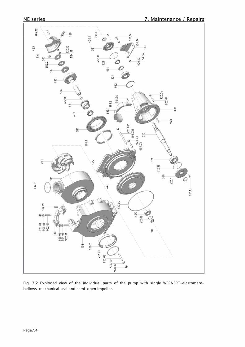
NE series 7. Maintenance / Repairs
Page7.4
Fig. 7.2 Exploded view of the individual parts of the pump with single WERNERT-elastomere-bellows-mechanical seal and semi-open impeller.

NE series 7. Maintenance / Repairs
Page7.5
7.3 Disassembly and assembly of the pump
Disassembly and assembly of the pump are explained in two series of photographs. As a standardtechnical design we have chosen the WERNERT- elastomer bellows mechanical seal and the lifetimeball bearings. If you are disassembling or assembling a pump with different shaft seals, please referto the drawings in these operating instructions resp. the specific sectional drawing. Themanufacturer also provides suitable product training upon request. Fig. 7.2 shows all the individualparts of this pump in the correct order of assembly. The tightening torques in Annex C must bemaintained.
7.3.1 Disassembly of the pumpAny work on the machine may on principle be done only with the electricjunctions disconnected. The pump aggregate must be protected fromunintended starting.Prior to being dismounted, the pump must be decontaminated and neutralized.Always wear suitable protective clothing! Contact with the liquid being pumpedmust be avoided under all circumstances! When draining the medium pumpedmake sure to avoid any danger to personnel and environment. Statutory
provisions must be complied with.
Fig. 7.3Complete pump aggregate.
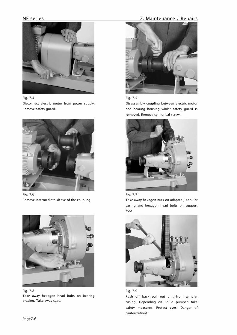
NE series 7. Maintenance / Repairs
Page7.6
Fig. 7.4Disconnect electric motor from power supply.Remove safety guard.
Fig. 7.5Disassembly coupling between electric motorand bearing housing whilst safety guard isremoved. Remove cylindrical screw.
Fig. 7.6Remove intermediate sleeve of the coupling.
Fig. 7.7Take away hexagon nuts on adapter / annularcasing and hexagon head bolts on supportfoot.
Fig. 7.8Take away hexagon head bolts on bearingbracket. Take away caps.
Fig. 7.9Push off back pull out unit from annularcasing. Depending on liquid pumped takesafety measures. Protect eyes! Danger ofcauterization!
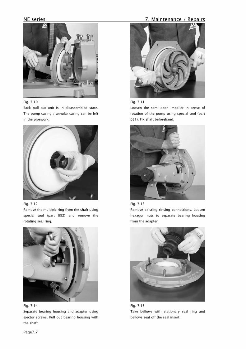
NE series 7. Maintenance / Repairs
Page7.7
Fig. 7.10Back pull out unit is in disassembled state.The pump casing / annular casing can be leftin the pipework.
Fig. 7.11Loosen the semi-open impeller in sense ofrotation of the pump using special tool (part051). Fix shaft beforehand.
Fig. 7.12Remove the multiple ring from the shaft usingspecial tool (part 052) and remove therotating seal ring.
Fig. 7.13Remove existing rinsing connections. Loosenhexagon nuts to separate bearing housingfrom the adapter.
Fig. 7.14Separate bearing housing and adapter usingejector screws. Pull out bearing housing withthe shaft.
Fig. 7.15Take bellows with stationary seal ring andbellows seat off the seal insert.
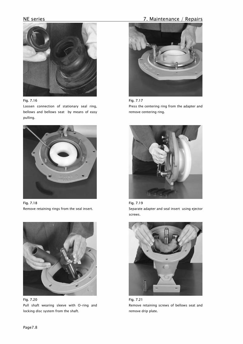
NE series 7. Maintenance / Repairs
Page7.8
Fig. 7.16Loosen connection of stationary seal ring,bellows and bellows seat by means of easypulling.
Fig. 7.17Press the centering ring from the adapter andremove centering ring.
Fig. 7.18Remove retaining rings from the seal insert.
Fig. 7.19Separate adapter and seal insert using ejectorscrews.
Fig. 7.20Pull shaft wearing sleeve with O-ring andlocking disc system from the shaft.
Fig. 7.21Remove retaining screws of bellows seat andremove drip plate.

NE series 7. Maintenance / Repairs
Page7.9
Fig. 7.22Pull coupling part from shaft end. Loosensafety screw first.
Fig. 7.23Remove key. Take shaft seal ring off the shaft.
Fig. 7.24Remove screws at bearing end cover.
Fig. 7.25Take off bearing end cover and O-ring.
Fig. 7.26Take shaft seal ring off the shaft. Remove thehexagon head bolts from the bearing cover.Remove bearing cover.
Fig. 7.27Push shaft with radial ball bearings off thebearing housing by carefully beating againstthe front face of the threaded journal with aplastic hammer.
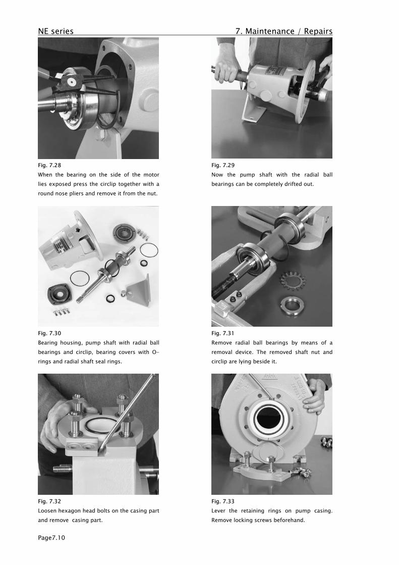
NE series 7. Maintenance / Repairs
Page7.10
Fig. 7.28When the bearing on the side of the motorlies exposed press the circlip together with around nose pliers and remove it from the nut.
Fig. 7.29Now the pump shaft with the radial ballbearings can be completely drifted out.
Fig. 7.30Bearing housing, pump shaft with radial ballbearings and circlip, bearing covers with O-rings and radial shaft seal rings.
Fig. 7.31Remove radial ball bearings by means of aremoval device. The removed shaft nut andcirclip are lying beside it.
Fig. 7.32Loosen hexagon head bolts on the casing partand remove casing part.
Fig. 7.33Lever the retaining rings on pump casing.Remove locking screws beforehand.
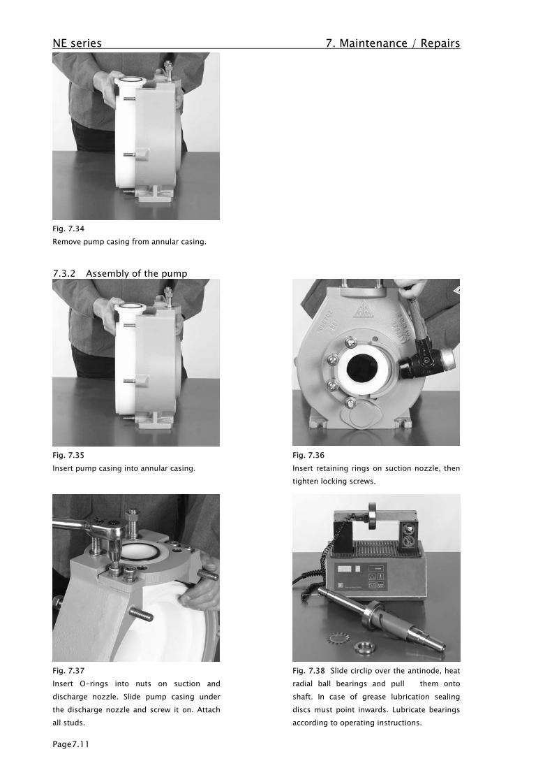
NE series 7. Maintenance / Repairs
Page7.11
Fig. 7.34Remove pump casing from annular casing.
7.3.2 Assembly of the pump
Fig. 7.35Insert pump casing into annular casing.
Fig. 7.36Insert retaining rings on suction nozzle, thentighten locking screws.
Fig. 7.37Insert O-rings into nuts on suction anddischarge nozzle. Slide pump casing underthe discharge nozzle and screw it on. Attachall studs.
Fig. 7.38 Slide circlip over the antinode, heatradial ball bearings and pull them ontoshaft. In case of grease lubrication sealingdiscs must point inwards. Lubricate bearingsaccording to operating instructions.
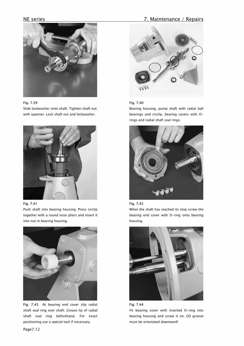
NE series 7. Maintenance / Repairs
Page7.12
Fig. 7.39Slide lockwasher onto shaft. Tighten shaft nutwith spanner. Lock shaft nut and lockwasher.
Fig. 7.40Bearing housing, pump shaft with radial ballbearings and circlip, bearing covers with O-rings and radial shaft seal rings.
Fig. 7.41Push shaft into bearing housing. Press circliptogether with a round nose pliers and insert itinto nut in bearing housing.
Fig. 7.42When the shaft has reached its stop screw thebearing end cover with O-ring onto bearinghousing.
Fig. 7.43 At bearing end cover slip radialshaft seal ring over shaft. Grease lip of radialshaft seal ring beforehand. For exactpositioning use a special tool if necessary.
Fig. 7.44Fit bearing cover with inserted O-ring intobearing housing and screw it on. Oil groovemust be orientated downward!

NE series 7. Maintenance / Repairs
Page7.13
Fig. 7.45 Slip radial shaft seal ring over shaftat bearing cover. Grease lip of radial shaftseal ring beforehand. For exact positioninguse a special tool if necessary.
Fig. 7.46Fasten the support foot to bearing housing.
Fig. 7.47Insert drip plate into bearing housing. Screwgrub screws into bearing cover and screw onnuts. Fit washers.
Fig. 7.48 Pull locking disc system and thenshaft wearing sleeve with O-ring onto shaft.Pay attention to orientation of the locking discsystem!
Fig. 7.49Assemble bellows with stationary seal ringand bellows seat. Take care to line up groovesand cams on all three components.
Fig. 7.50Place pre-assembled bellows seat onto thepins.
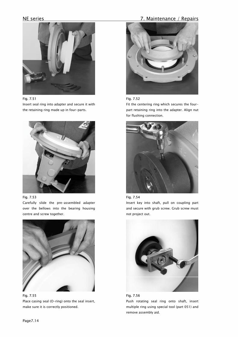
NE series 7. Maintenance / Repairs
Page7.14
Fig. 7.51Insert seal ring into adapter and secure it withthe retaining ring made up in four-parts.
Fig. 7.52Fit the centering ring which secures the four-part retaining ring into the adapter. Align nutfor flushing connection.
Fig. 7.53Carefully slide the pre-assembled adapterover the bellows into the bearing housingcentre and screw together.
Fig. 7.54Insert key into shaft, pull on coupling partand secure with grub screw. Grub screw mustnot project out.
Fig. 7.55Place casing seal (O-ring) onto the seal insert,make sure it is correctly positioned.
Fig. 7.56Push rotating seal ring onto shaft, insertmultiple ring using special tool (part 051) andremove assembly aid.
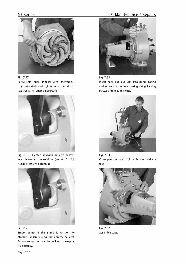
NE series 7. Maintenance / Repairs
Page7.15
Fig. 7.57Screw semi-open impeller with inserted O-ring onto shaft and tighten with special tool(part 051). Fix shaft beforehand.
Fig. 7.58Insert back pull-out unit into pump casingand screw it to annular casing using lockingscrews and hexagon nuts.
Fig. 7.59 Tighten hexagon nuts on bellowsseat following instructions (section 6.1.4.).Avoid excessive tightening!
Fig. 7.60Close pump nozzles tightly. Perform leakagetest.
Fig. 7.61Empty pump. If the pump is to go intostorage, loosen hexagon nuts on the bellows.By loosening the nuts the bellows is keepingits elasticity.
Fig. 7.62Assemble caps.

NE series 7. Maintenance / Repairs
Page7.16
7.4 Spare parts
On principle, replacement parts should only be ordered according to a parts list belonging to thepump stating the identification number of the part and / or the serial number of the pump. Onprinciple, every individual part can be supplied. Standard parts are always in stock at themanufacturer's or his representatives and this guarantees short delivery periods. However, werecommend that the client should also keep the parts listed below in his stores.
All parts of the mechanical seal, i.e. for the single WERNERT-elastomere-bellows-mechanical seal,which come into contact with liquid need to be replaced after one year (9,000 operating hours):
- Part 472 Stationary seal ring- Part 475 Rotating seal ring- Part 481 BellowsThe following O-rings should also be replaced regularly:- Part 412.04 O-ring (casing seal)- Part 412.05 O-ring (shaft wearing sleeve)- Part 412.06 O-ring (impeller)
For the single WERNERT-elastomere-bellows-mechanical seal, the following parts are regarded asreplacement parts after two years of operation of the pump:
- Part 210 Shaft- Part 233 Left hand impeller- Part 321 Radial ball bearing (2 pieces)- Part 412.01 O-ring (discharge nozzle)- Part 412.03 O-ring (suction nozzle)- Part 412.36 O-ring (bearing)- Part 420.1 Shaft seal ring (on bearing cover)- Part 420.3 Shaft seal ring (on bearing end cover)- Part 482 Bellows seat- Part 501 Multiple ring- Part 505 Loose collar- Part 507 Thrower- Part 524 Shaft wearing sleeve- Part 552.2 Spanner (in locking system for shaft wearing sleeve)- Part 921 Shaft nut- Part 931 Lockwasher- Part 932 Circlip- Part 940 Key
In case of oil lubrication:- Part 322 Radial rollerbearing- Part 323 Thrust ball bearing
The manufacturer can at any time - if the serial number of pump is stated - provide an offer for thereplacement parts required for the pump in question.

NE series 8. Faults; causes and remedies
Page 8.1
8. Faults; causes and remediesFault Possible cause Rectification8.1 Pump notpumping even thoughengine is working.
8.1.1 Pump not filled sufficientlybefore starting up.
Refill again and de-air.
8.1.2 Storage container empty orliquid level below inlet nozzle ofsuction line, therefore no liquidis flowing.
Install automatic monitoring device. Trainpersonnel.
8.1.3 Suction height too great,therefore liquid does not flow.
Position pump lower, and / or position liquidlevel higher.
8.1.4 Pump sucking in additional air,therefore liquid does not flow.
Check suction pipe and shaft seal for leaks.
8.1.5 Air sac formation in the pipes,therefore no liquid flow.
Lay pipes correctly. Check position of fittings.If necessary fit de-airing fittings.
8.1.6 The overall delivery head isgreater than that stated.
Adapt plant to suit pump or vice versa,otherwise use different pump.
8.1.7 Impeller melted open in the hubregion or has been destroyeddue to faults as described in8.6, 8.7 or 8.8.
Repair pump, check operational conditions.Train personnel.
8.1.8 Shaft broken in the pump. Repair pump, check operational conditions,train personnel.
8.2 Flow and / ordelivery head to small.
8.2.1 Direction of rotation of pump isincorrect.
Change direction of motor to ensure pumprotates in the right direction. Check pump fordamage before starting up again.
8.2.2 Plant conditions do not agreewith pump design.
Adapt plant to suit pump or vice versa, ifnecessary use a different pump.
8.2.3 High pressure losses inunfavourably laid pipes.
Increase diameter of pipes and fittings, avoidbends, create favourable transitions.
8.2.4 Pipes or pump blocked. Clean sieve, filter, pipes, fittings and pump.8.2.5 High pressure loss in suction
pipe, therefore cavitation.Clean suction basket or suction pipe, possiblyincrease diameter of suction pipe. Check footvalve to see if it opens fully.
8.2.6 Suction height too great,therefore cavitation.
Position pump lower and / or position level ofliquid higher.
8.2.7 Temperature of liquid to bepumped too high, thereforecavitation.
Reduce temperature of liquid to be pumpedand / or increase initial pressure.
8.2.8 High proportion of gas in liquidto be pumped.
Calm liquid to be pumped. Prevent waterspouts using guide crosses. Lengthencirculation times. Make gassing out possible.
8.2.9 Viscosity of liquid to be pumpedhigher than originally assumed.
Adapt pump, if necessary use a differentpump. Alternative: Dilute or heat liquid to bepumped.
8.2.10 Impeller worn due to abrasion. Replace impeller.
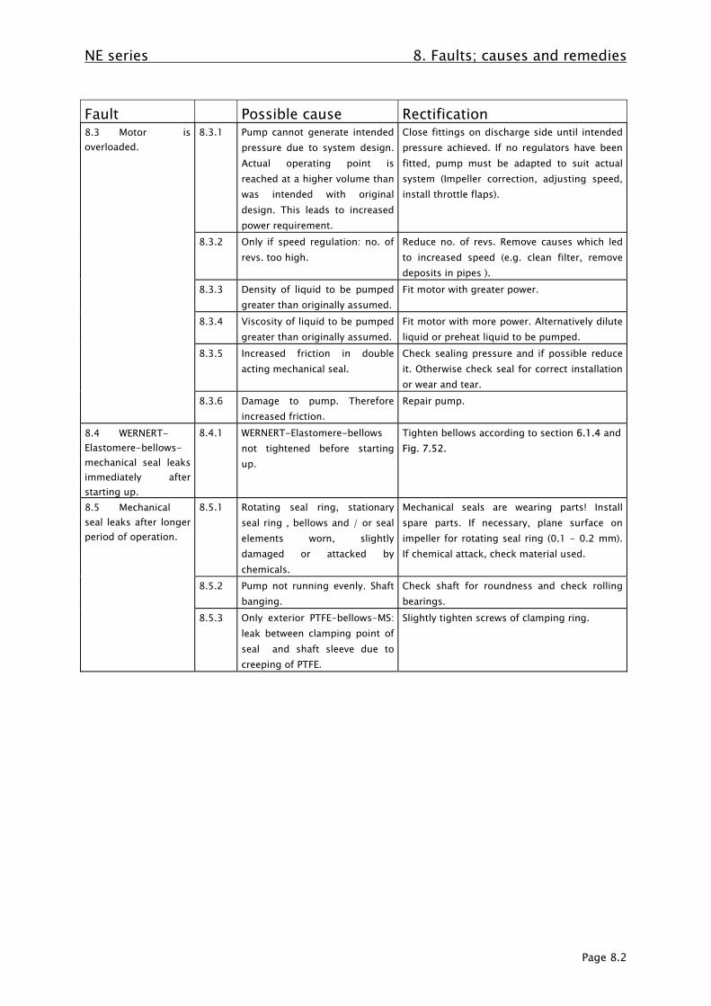
NE series 8. Faults; causes and remedies
Page 8.2
Fault Possible cause Rectification8.3 Motor isoverloaded.
8.3.1 Pump cannot generate intendedpressure due to system design.Actual operating point isreached at a higher volume thanwas intended with originaldesign. This leads to increasedpower requirement.
Close fittings on discharge side until intendedpressure achieved. If no regulators have beenfitted, pump must be adapted to suit actualsystem (Impeller correction, adjusting speed,install throttle flaps).
8.3.2 Only if speed regulation: no. ofrevs. too high.
Reduce no. of revs. Remove causes which ledto increased speed (e.g. clean filter, removedeposits in pipes ).
8.3.3 Density of liquid to be pumpedgreater than originally assumed.
Fit motor with greater power.
8.3.4 Viscosity of liquid to be pumpedgreater than originally assumed.
Fit motor with more power. Alternatively diluteliquid or preheat liquid to be pumped.
8.3.5 Increased friction in doubleacting mechanical seal.
Check sealing pressure and if possible reduceit. Otherwise check seal for correct installationor wear and tear.
8.3.6 Damage to pump. Thereforeincreased friction.
Repair pump.
8.4 WERNERT-Elastomere-bellows-mechanical seal leaksimmediately afterstarting up.
8.4.1 WERNERT-Elastomere-bellowsnot tightened before startingup.
Tighten bellows according to section 6.1.4 andFig. 7.52.
8.5 Mechanicalseal leaks after longerperiod of operation.
8.5.1 Rotating seal ring, stationaryseal ring , bellows and / or sealelements worn, slightlydamaged or attacked bychemicals.
Mechanical seals are wearing parts! Installspare parts. If necessary, plane surface onimpeller for rotating seal ring (0.1 - 0.2 mm).If chemical attack, check material used.
8.5.2 Pump not running evenly. Shaftbanging.
Check shaft for roundness and check rollingbearings.
8.5.3 Only exterior PTFE-bellows-MS:leak between clamping point ofseal and shaft sleeve due tocreeping of PTFE.
Slightly tighten screws of clamping ring.

NE series 8. Faults; causes and remedies
Page 8.3
Fault Possible cause Rectification8.6 Singlemechanical seal isdestroyedspontaneously andtherefore leaks.
8.6.1 The pump has run dry, i.e. thereis no liquid in the entire pump.Hence the sliding faces overheatand they are thermally /mechanically destroyed plusfrequently plastic parts nearbysuch as impeller and bellows aredestroyed by the heat (so-calledrunning hot).
Running dry is a typical operating error. Thepump must be filled completely and de-airedbefore it is started up. Fittings on the suctionside must be completely open. Train personnelaccordingly. Repair pump.
8.6.2 Semi- running -dry in case ofstall, i.e. even though a liquidring is rotating with theimpeller, it does not reach theinterior sliding faces. Thereforethe seal runs hot.
Take measures to prevent flow beinginterrupted. Install automatic monitoringdevice. Train personnel. Repair pump. Equipsingle mechanical seal with continuous rinsingor if necessary install double acting mechanicalseal.
8.6.3 Due to increased gas particles inliquid being pumped, a gas ringis formed around the rotatingand stationary seal rings. Thisgas is pressed through thesliding surfaces by the excesspressure on the pump.Therefore the seal runs hot.
Calm liquid being pumped. Prevent waterspout by using guiding crosses. Lengthencirculating times. Make de-gassing possible.Repair pump. Equip single mechanical sealwith continuous rinsing or if necessary equipwith double acting mechanical seal.
8.6.4 The liquid is virtually beingpumped at boiling temperature.Due to the increase intemperature in the seal gap, dueto friction and simultaneousdecrease in pressure, the liquidbeing pumped evaporates in theseal gap. Possible crystals in theliquid might crystallise out.Therefore the seal runs hot.
Repair pump. Equip single mechanical sealwith continuos rinsing or possibly equip withdouble acting mechanical seal.
8.6.5 High pressure losses on thesuction side due to blockage orthrottled fittings cause a lowpressure at the mechanical seal.Air is sucked from theatmosphere through the slidingsurfaces. Seal runs hot.
Minimise losses on suction size. Trainpersonnel accordingly. Possibly decreasediameter of vane on the back of the impeller.Equip single mechanical seal with quench orpossibly equip with double acting mechanicalseal.
8.6.6 Due to pressure losses on thesuction side due to increasedvolume of liquid being pumpedwith simultaneous pressuredecrease on pressure nozzlecauses low pressure in the areaof the mechanical seal. Air issucked from the atmospherethrough the sliding areas.Seal runs hot.
Throttle pressure side fittings in order to getinto the admissible operational range. Trainpersonnel accordingly. Repair pump. Possiblydecrease diameter of vane on the back of theimpeller. Equip single mechanical seal withquench or possibly equip with double actingmechanical seal.

NE series 8. Faults; causes and remedies
Page 8.4
Fault Possible cause Rectification8.7 Pump isdestroyed by "runningin its own juice".
8.7.1 Pump running "in its own juice",i.e. drive performance iscompletely transformed intoincreased pump temperatures ifliquid cannot be exchangedproperly. This occurs if fittingson pressure side remains closedafter pump has been startedup...
After starting up pump open fittings onpressure side at least so far that the minimumpumping volume is achieved. Train personnelaccordingly. If necessary install automaticdevice. Repair pump.
8.7.2 or the pipe lines are blocked... Clean pipelines, repair pump.8.7.3 or the static head of the system
is not achieved by the pump.Adapt system to suit pump or vice versa,possibly use different pump.
8.8 Pump isdestroyed because itwas rotating thewrong way.
8.8.1 Pump rotating in the wrongdirection. (Impeller started up,hub thread torn out of impeller,bearing cover destroyed, liquidno longer being pumped.)
Change poles on motor in order to achievecorrect direction of rotation for the pump.Repair pump.
8.9 Increasedbearing temperature.
8.9.1 Motor aligned badly (Couplinghalves are displaced in an axial,radial, angled direction).
Realign motor. Ensure axial coupling distanceof 5 - 6 mm.
8.9.2 Increased axial and / or radialforces because pump is beingoperated with volumes whichare too small or too large.
Operate pump with permissible volumes.
8.9.3 Pump body is twisted by pipes. Change position of pipes or position of pumpto remove tension. Then align motor. Possiblyposition aggregate freely.
8.9.4 Not sufficient, too much, usedor unsuitable grease or oil.
Correct this situation.
8.10 Unevenrunning (noises,vibrations)
8.10.1 Motor aligned badly (Couplinghalves are displaced in an axial,radial, angled direction).
Realign motor, make sure axial couplingdistance is 5 - 6 mm.
8.10.2 Coupling packets worn. Replace coupling packets.8.10.3 Bearing is damaged. Replace roller bearings and shaft seal rings.8.10.4 Not fixed tightly to foundation. Tighten fixing screws and anchors.8.10.5 Cavitation. Take measure to avoid cavitation:
- reduce volume being pumped - increase preliminary pressure - reduce losses on suction side
NE series 9. Associated documentation
Page 9.1
9. Associated documentationEach pump of the NE series is supplied with these operating instructions.
Other documentation which describes the pump is not included in delivery as standard. The scope ofthe documentation to be delivered is agreed for each order separately.

Type NE Annex A: Name Plate
Page 10.1
10. Annex A: Name Plate
10.1 Design of the name plate
The design of the name plate is explained by means of code letters a – o.
Figure A.1 Name plate with code lettersField a = Type designationField b = Serial numberField c = Impeller: Diameter in mmField d = Impeller: Blade height in mmField e = Impeller: Blade numberField f = Possible throttling bush: Diameter in mmField g = Nominal flow rate Q in m³/hField h = Nominal delivery head H in mField i = Nominal speed in 1/minField k = Coupling power with density as per Field l / nominal drive power, each in kWField l = Liquid density in kg/dm³Field m = WERNERT mechanical seal code (WGC), please also refer to Section A.2Field n = Mechanical seal materials, product-side, please also refer to Section A.3Field o = Material of the shaft sleeve, product-side, please also refer to Section A.3
Figure A.2 Exemplary name plate

Type NE Annex A: Name Plate
Page 10.2
10.1.1 Additional name plate for pumps according to EC Council Directive 94/9/EC
Degree of explosion protectionII Equipment group II applies to equipment for application in areas which may be endangered by
an explosive atmosphere. Except for underground workings of mines and their surfaceinstallations which may be endangered by fire damp and/or combustible dust.
2G Category 2 comprises machines of such a structural design that they can be operated inagreement with the characteristic quantities specified by the manufacturer assuring a high degreeof safety. Machines of this category are intended for use in areas where an explosive atmosphereof gases, vapours, fogs may be occasionally expected. Even in case of frequent equipmenttroubles or fault conditions which are normally to be expected, the explosion protection measuresof this category of equipment assure the required degree of safety.
c Constructional-safety type of protection "c" is a type of explosion protection wherestructural measures are taken to assure protection against potential ignition due to hot surfaces,sparks and adiabatic compressions (EN 13463-5).
TX Temperature classes T1 – T6 of which only temperature classes T1 to T4 are currentlyadmitted. As the maximum surface temperature mainly depends on the operating conditions(heated liquid in the pump, refer to temperature limits 2.9.7 above), the manufacturer must notprovide any designation with a temperature or temperature class (EN 13463-1, 14.2 g).
CE Conformity marking
Special marking for theprevention of explosions
Reference number of the technical documentationYear of construction
X The admissible area of the ambient temperature is –10 °C up to +40 °C. Behind the number ofthe technical documentation, the name plate is provided with the symbol "X" as an additional markingfor the limited ambient temperature.
Type NE Annex A: Name Plate
Page 10.3
10.2 WERNERT mechanical seal code (WGC)
In the field m of the name plate, the design of the mechanical seal is entered by means of a code whichalways consists of three capital letters.
The first letter encrypts the general design:C = Cartridge sealing according to EN 12756, metal-free design within the liquid areaD = Double seal according to EN 12756 (back-to-back), design K, shape UUE = Single-acting mechanical seal with stationary spring suspension and secondary O-ring sealF = Single-acting external mechanical seal with rotating PTFE bellowsK = Single-acting mechanical seal with rotating tapered ringR = Single-acting mechanical seal with rotating spring suspension and secondary O-ring sealS = Stationary double sealW = WERNERT bellows-type mechanical sealsX = Special design
The second letter encrypts the manufacturer of the mechanical seal:B = BurgmannC = CraneD = DurametallicH = WERNERT -CSM bellowsM = MerkelP = PacificT = WERNERT-PTFE bellowsV = WERNERT-FPM bellows
The third letter then distinguishes the special designs. More detailed information is available from themanufacturer.
The following codes apply to WERNERT bellows-type mechanical seals:
WERNERT CSM bellows WERNERT FPM bellows WERNERT PTFE bellowsInternal flushing WHN WVN WTNPermanent flushing WHD WVD WTDConditional flushing WHS WVS WTSQuench WHQ WVQ WTQQuench, permanent flushing WHP WVP WTPQuench, conditional flushing WHR WVR WTRConditional quench WHA WVA WTAConditional quench,permanent flushing
WHB WVB WTB
Conditional quench,conditional flushing
WHC WVC WTC
Special design WHX WVX WTX

Type NE Annex A: Name Plate
Page 10.4
10.3 Mechanical seal materials
The mechanical seal materials are coded according to the material code in EN 12756, for double-actingmechanical seals, however, only the side facing the liquid is mentioned. In field n, 5 materials must beindicated:
1st figure: Material of the rotating seal ring (this is always the spring-suspended ring)2nd figure: Material of the stationary seal ring3rd figure: Material of the auxiliary gaskets (any additional material in parentheses)4th figure: Material of the spring (if available)5th figure: Material of the other structural parts
Field o: Material of the shaft sleeve
The following materials are used for WERNERT bellows-type mechanical seals:
1st/2nd figure:B = Carbon (synthetic-resin impregnated)C = Special carbonQ1 = SSiC (Silicon carbide, sintered at zero pressure)V = Aluminum oxide ceramicsY1 = PTFE, glass-reinforcedY2 = PTFE, carbon-reinforced
3rd figure:H = CSMT = PTFEV = FPM
4th figure:- = Spring not available in case of WERNERT elastomer bellowsT = 1.1200 / Halar (other materials according to standard), in case of WERNERT PTFE bellows
5th figure:- = Other structural parts not available
Field o :B = Carbon (synthetic-resin impregnated)C = Special carbonG = 1.4571M1 = Hastelloy BM2 = Hastelloy CQ1 = SSiC (Silicon carbide, sintered at zero pressure)Ti = TitaniumV = Aluminum oxide ceramics
Fur further material identifications, please refer to Standard EN 12756.

Type NE Annex B: Admissible Branch Loads, Speeds
Page 11.1
11. Annex B: Admissible Branch Loads, SpeedsThe admissible branch loads listed in Table B.1 are in line with API 610. The x axis is coaxial to thepump shaft, the y axis is the vertical line, and the z axis the horizontal line. The forces and momentslisted can be taken up irrespective of their direction.Type series NE Size Bearing
housing/Max. speed
Vertical forces Horizontal forces Moments
Suctionbranch
Deliverybranch
Suctionbranch
Deliverybranch
Suction br./
Delivery br.
Suction br./
Delivery br.
Suction br/
Delivery br.
Size
Size [-] /speed[1/min] Fy [N] Fy [N] Fx/Fz
[N]Fx/Fz [N] Mx [Nm] My [Nm] Mz [Nm]
40-25-160 03500
±467 ±601 ±779/±579
±423/±334
±366/±203
±271/±149
±176/±81
50-32-160 13500
±579 ±690 ±890/±712
±512/±401
±461/±271
±353/±210
±230/±129
50-32-200 13500
±579 ±690 ±890/±712
±512/±401
±461/±271
±353/±210
±230/±129
50-32-250 23500
±579 ±690 ±890/±712
±512/±401
±461/±271
±353/±210
±230/±129
65-40-200 13500
±712 ±779 ±1113/±890
±579/±467
±705/±366
±664/±271
±353/±176
65-40-250 23500
±712 ±779 ±1113/±890
±579/±467
±705/±366
±664/±271
±353/±176
80-50-200 13500
±890 ±890 ±1335/±1068
±712/±579
±949/±461
±719/±353
±475/±230
80-50-250 23500
±890 ±890 ±1335/±1068
±712/±579
±949/±461
±719/±353
±475/±230
80-50-315 21750
±890 ±890 ±1335/±1068
±712/±579
±949/±461
±719/±353
±475/±230
100-65-250 23500
±1157 ±1113 ±1780/±1424
±890/±712
±1329/±705
±1003/±664
±678/±353
125-80-200 23500
±1558 ±1335 ±2403/±1891
±1068/±890
±1763/±949
±1356/±719
±922/±475
125-80-250 23500
±1558 ±1335 ±2403/±1891
±1068/±890
±1763/±949
±1356/±719
±922/±475
125-80-315 31750
±1558 ±1335 ±2403/±1891
±1068/±890
±1763/±949
±1356/±719
±922/±475
125-100-200 23500
±1558 ±1780 ±2403/±1891
±1424/±1157
±1763/±1329
±1356/±1003
±922/±678
125-100-250 33500
±1558 ±1780 ±2403/±1891
±1424/±1157
±1763/±1329
±1356/±1003
±922/±678
125-100-315 31750
±1558 ±1780 ±2403/±1891
±1424/±1157
±1763/±1329
±1356/±1003
±922/±678
150-125-315 31750
±2047 ±2403 ±3115/±2492
±1891/±1558
±2305/±1763
±1763/±1356
±1180/±922
200-150-250 31750
±3115 ±3115 ±4895/±3783
±2492/±2047
±3525/±2305
±2576/±1763
±1763/±1180
200-150-400 41750
±3115 ±3115 ±4895/±3783
±2492/±2047
±3525/±2305
±2576/±1763
±1763/±1180
250-200-400 41750
±4450 ±4895 ±6675/±5340
±3783/±3115
±5016/±3525
±3796/±2576
±2440/±1763
Tabelle B.1 Admissible branch loads and maximum speeds for Type NE
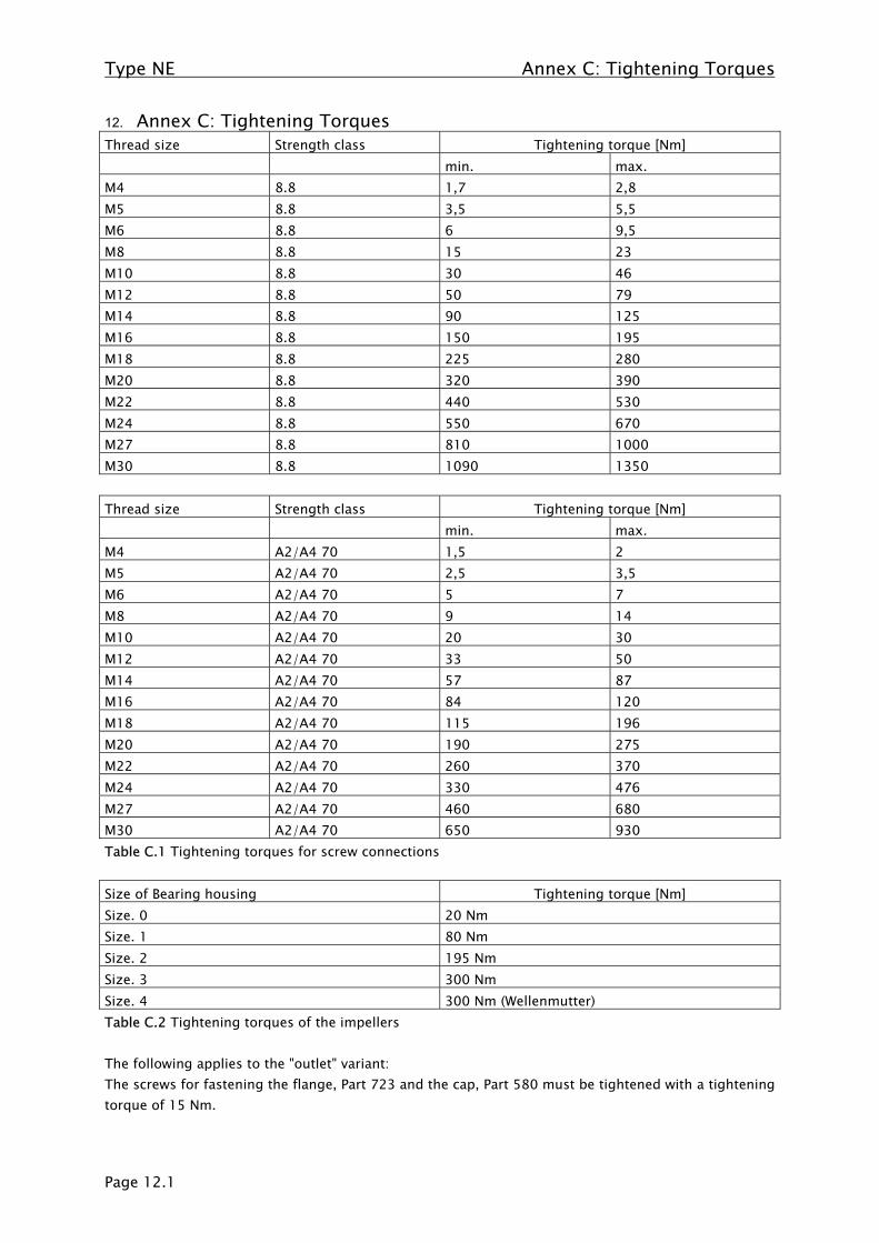
Type NE Annex C: Tightening Torques
Page 12.1
12. Annex C: Tightening TorquesThread size Strength class Tightening torque [Nm]
min. max.M4 8.8 1,7 2,8M5 8.8 3,5 5,5M6 8.8 6 9,5M8 8.8 15 23M10 8.8 30 46M12 8.8 50 79M14 8.8 90 125M16 8.8 150 195M18 8.8 225 280M20 8.8 320 390M22 8.8 440 530M24 8.8 550 670M27 8.8 810 1000M30 8.8 1090 1350
Thread size Strength class Tightening torque [Nm]min. max.
M4 A2/A4 70 1,5 2M5 A2/A4 70 2,5 3,5M6 A2/A4 70 5 7M8 A2/A4 70 9 14M10 A2/A4 70 20 30M12 A2/A4 70 33 50M14 A2/A4 70 57 87M16 A2/A4 70 84 120M18 A2/A4 70 115 196M20 A2/A4 70 190 275M22 A2/A4 70 260 370M24 A2/A4 70 330 476M27 A2/A4 70 460 680M30 A2/A4 70 650 930Table C.1 Tightening torques for screw connections
Size of Bearing housing Tightening torque [Nm]Size. 0 20 NmSize. 1 80 NmSize. 2 195 NmSize. 3 300 NmSize. 4 300 Nm (Wellenmutter)Table C.2 Tightening torques of the impellers
The following applies to the "outlet" variant:The screws for fastening the flange, Part 723 and the cap, Part 580 must be tightened with a tighteningtorque of 15 Nm.
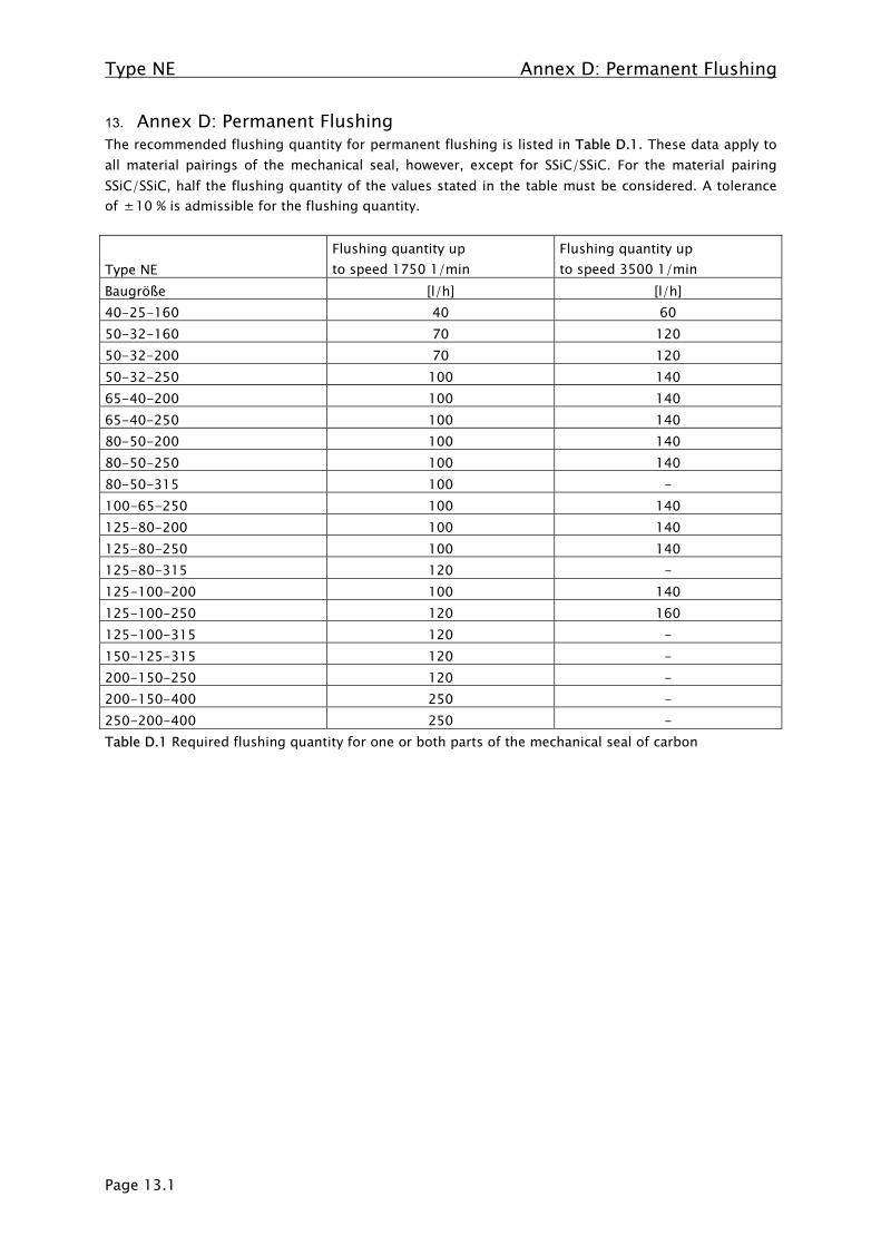
Type NE Annex D: Permanent Flushing
Page 13.1
13. Annex D: Permanent FlushingThe recommended flushing quantity for permanent flushing is listed in Table D.1. These data apply toall material pairings of the mechanical seal, however, except for SSiC/SSiC. For the material pairingSSiC/SSiC, half the flushing quantity of the values stated in the table must be considered. A toleranceof ±10 % is admissible for the flushing quantity.
Type NEFlushing quantity upto speed 1750 1/min
Flushing quantity upto speed 3500 1/min
Baugröße [l/h] [l/h]40-25-160 40 6050-32-160 70 12050-32-200 70 12050-32-250 100 14065-40-200 100 14065-40-250 100 14080-50-200 100 14080-50-250 100 14080-50-315 100 -100-65-250 100 140125-80-200 100 140125-80-250 100 140125-80-315 120 -125-100-200 100 140125-100-250 120 160125-100-315 120 -150-125-315 120 -200-150-250 120 -200-150-400 250 -250-200-400 250 -Table D.1 Required flushing quantity for one or both parts of the mechanical seal of carbon