operating manual air pycnometer - ugt umwelt-geräte-technik · 2019-01-10 · the air pycnometer...
TRANSCRIPT

Operating Manual
Air Pycnometer Version: 24/05/17
Umwelt-Geräte-Technik GmbH
Eberswalder Str. 58 | D-15374 Müncheberg
phone: +49 (0) 33 43 2 - 89 575 | fax: +49 (0) 33 43 2 - 89 573
e-Mail: [email protected] | www.ugt-online.de
Umwelt-Geräte-Technik GmbH | Eberswalder Str. 58 | D-15374 Müncheberg | phone: +49 (0) 33 43 2 - 89 575 | www.ugt-online.de Page 2 of 14
Content
1. Introduction .......................................................................................................................................3
2. General Information...........................................................................................................................3
2.1. What is an Air Pycnometer used for? ...............................................................................................3
2.2. How Does an Air Pycnometer Work? ...............................................................................................3
3. Set Up and Technical Parameters .......................................................................................................6
3.1. Set Up ..............................................................................................................................................6
3.2. Technical Parameters ......................................................................................................................6
4. Measurement Procedure ...................................................................................................................7
4.1. Calibration .......................................................................................................................................7
4.2. Measuring Process ...........................................................................................................................8
5. Handling of the Digital Manometer ..................................................................................................11
6. Evaluation ........................................................................................................................................12
6.1. Using the Excel-file “Evaluation Air Pycnometer” ...........................................................................12
6.2. Errors and Advices for effective Measurements .............................................................................13

Umwelt-Geräte-Technik GmbH | Eberswalder Str. 58 | D-15374 Müncheberg | phone: +49 (0) 33 43 2 - 89 575 | www.ugt-online.de Page 3 of 14
1. Introduction
The warranty for this product is based on the provisions of sections 7 to 9 of our General Terms and
Conditions, which you find in the appendix.
If a defect is found in our product, please notify us immediately by fax or e-mail.
2. General Information
2.1. What is an Air Pycnometer used for?
The air pycnometer is an innovative measuring device for the determination of the air filled pore volume, the solids volume, and the particle density of a substrate sample in the laboratory.
The pore volume is a relevant parameter for soil specification. It provides important information for many questions of water balance studies, cultivation of land or land reclamation. Air- and water conductivity as well as water- and nutrient retention are directly connected to the pore volume.
The air pycnometer is suitable for undisturbed soil samples as well as for bulk solids like sand, gravel or plant pellets. It provides faster and easier measurements compared to glass pycnometers. A high content of fine particles may reduce the applicability of the gas pycnometer.
Due to the big measurement chamber with a volume of 2120 cm³ it is possible to investigate samples of large volume.
2.2. How Does an Air Pycnometer Work?
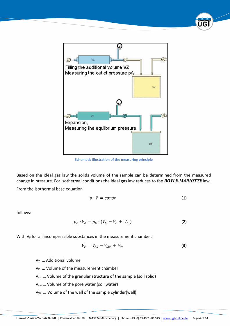
The measurement method is based on the fact that only the solids volume displaces gas while pore or cavity volumes are filled with gas. The air pycnometer consists of two connected chambers, a measurement chamber and an additional volume chamber. The additional volume chamber is filled with compressed air and connected via a shut-off valve to the measurement chamber that contains the sample. Opening the shut-off valve leads to pressure equalization between both chambers.
Umwelt-Geräte-Technik GmbH | Eberswalder Str. 58 | D-15374 Müncheberg | phone: +49 (0) 33 43 2 - 89 575 | www.ugt-online.de Page 4 of 14
Schematic illustration of the measuring principle
Based on the ideal gas law the solids volume of the sample can be determined from the measured change in pressure. For isothermal conditions the ideal gas law reduces to the BOYLE-MARIOTTE law.
From the isothermal base equation
𝑝 ∙ 𝑉 = 𝑐𝑜𝑛𝑠𝑡 (1)
follows:
𝑝𝐴 ∙ 𝑉𝑍 = 𝑝𝐸 ∙ (𝑉𝐾 − 𝑉𝐹 + 𝑉𝑍 ) (2)
With VF for all incompressible substances in the measurement chamber:
𝑉𝐹 = 𝑉𝑆𝑆 − 𝑉𝑆𝑊 + 𝑉𝑊 (3)
VZ … Additional volume
VK … Volume of the measurement chamber
Vss … Volume of the granular structure of the sample (soil solid)
Vsw … Volume of the pore water (soil water)
VW … Volume of the wall of the sample cylinder(wall)
Umwelt-Geräte-Technik GmbH | Eberswalder Str. 58 | D-15374 Müncheberg | phone: +49 (0) 33 43 2 - 89 575 | www.ugt-online.de Page 5 of 14
The volumes VK and VZ are determined by calibration.
By transponsing equation (2) one derives:
𝑉𝐹 = 𝑉𝐾 −(𝑝𝐴 − 𝑝𝐸)
𝑝𝐸 ∙ 𝑉𝑍 (4)
For a dry sample without test cylinder VF equates the volume of the granular structure (Vss)
The evaluation of the air filled pore volume VL follows from:
𝑉𝐿 = 𝑉𝑆 − 𝑉𝐹 (5)
VL … volume of air filled pores = Volume of soil air
Vs … Volume of the whole sample
Inserting (3) into (4) and rearranging to the relevant components on the left side of the equation results in:
𝑉𝑆𝑆 + 𝑉𝑆𝑊 = 𝑉𝐾 −(𝑝𝐴 − 𝑝𝐸)
𝑝𝐸 ∙ 𝑉𝑍 − 𝑉𝑊 (6)
After inserting (6) in (5) one gets the air filled pore volume:
𝑉𝐿 = 𝑉𝑆 − 𝑉𝐾 −(𝑝𝐴 − 𝑝𝐸)
𝑝𝐸 ∙ 𝑉𝑍 − 𝑉𝑊 (7)

Umwelt-Geräte-Technik GmbH | Eberswalder Str. 58 | D-15374 Müncheberg | phone: +49 (0) 33 43 2 - 89 575 | www.ugt-online.de Page 6 of 14
3. Set Up and Technical Parameters
3.1. Set Up
By default ambient air is used as measuring gas (air pycnometer). Different measuring gases can be used optional via a separate inlet pipe (gas pycnometer).
The measurement chamber is fixed to the device body and gets shut with a lid that gets pressed on by a clamp with a tensioning screw. Therefore, a sample cylinder or soil sample ring is not necessary to run measurements.
3.2. Technical Parameters
Measurement Chamber:
Height 12 cm
Ø 15 cm
Volume ≈ 2120 cm³

Umwelt-Geräte-Technik GmbH | Eberswalder Str. 58 | D-15374 Müncheberg | phone: +49 (0) 33 43 2 - 89 575 | www.ugt-online.de Page 7 of 14
Pressure vessel (additional volume):
Volume ≈ 1000 cm³
Digital Manometer:
Manufacturer Keller
Model Leo 1
Pressure Range -1 bis 3 bar
Resolution 1 mbar
Overpressure 10 bar
Accuracy RT (room temperature) < 0,1 %FS
Total Error Band (0…50°C) < 0,2 %FS
Storage- / Operating Temperature -20…70 °C / 0…50 °C
Compensated Temperature Range 0…50 °C
Supply 3 V Battery, CR 2430
Battery Life •1000 hours continuously in Mano-mode
•150 hours continuously in Peak-mode
Pressure Connection G1/4”
Protection CEI529 IP65
4. Measurement Procedure
4.1. Calibration
The calibration is carried out according to DIN 66137-2:2004-12. The calibration of the volumes of the pressure vessel and the measurement chamber are carried out stepwise using calibration blocks (glass cylinder) of known volume (Vkal). Either a single calibration block or a combination of two or three blocks can be used for the calibration.
Note The scope of supply includes three blocks of known volume. The blocks can also be used to artificially reduce the volume of the measurement chamber when working with small soil samples. This procedure provides more stable results due to a smaller influence of measurement errors.
Umwelt-Geräte-Technik GmbH | Eberswalder Str. 58 | D-15374 Müncheberg | phone: +49 (0) 33 43 2 - 89 575 | www.ugt-online.de Page 8 of 14
The pressure in the measurement chamber and in the additional volume chamber has to be equalized to the atmosphere by opening both valves (that means position “venting” at the three-way valve). If a different measuring gas is used (optional) the measurement chamber and the pressure vessel have to be flushed and filled with the measuring gas.
These initial conditions have to be realized before each step of the calibration, i.e. after opening the measurement chamber.
In the first step of the calibration the measuring pressure pA,1 is set up in the pressure vessel. The expansion takes place in the empty measurement chamber (equilibrium pressure pE,1). The second step is carried out analogous to step one with the calibration block located in the measurement chamber. Again the initial pressure pA,2 before the expansion and the equilibrium pressure pE,2
after the expansion have to be measured. Following equations apply for the volume of the measurement chamber VK and the additional volume VZ:
𝑉𝐾 = 𝑝𝐸,2 ∙ 𝑝𝐴,1 − 𝑝𝐸,1
𝑝𝐴,1 ∙ 𝑝𝐸,2 − 𝑝𝐴,2 ∙ 𝑝𝐸,1 ∙ 𝑉𝑘𝑎𝑙 (8)
𝑉𝑧 = 𝑝𝐸 ,1
𝑝𝐴,1 − 𝑝𝐸 ,1 ∙ 𝑉𝑘 (9)
Changes in the measuring gas, its pureness or in the measuring pressure compared to the previous calibration necessitate a new calibration. It is recommended to make a calibration before each measuring campaign.
For an exact calibration measurements should be taken redundant and analyzed statistically (see Excel-file „Evaluation Air Pycnometer”).
4.2. Measuring Process
Debris at the sealing ring may confine its functionality. To keep the air pycnometer work correctly always use the plastic ring to cover the sealing ring while the measurement chamber is open.
At the beginning of a measuring sequence the three-way valve *5+ has to be in the “venting”-position, the lock valve [7] is completely opened and the lid is removed from the measurement chamber, that the complete system is under current atmospheric pressure. Pushing the “Enter”-button switches on the digital manometer [6], the pressure has to be logged as current air-pressure.
The sample container/sample (VF) is put in the measurement chamber (VK), which is hermetically sealed by putting on the lid and hand-tight screwing of the tensioning screw. Thereby the displayed pressure should not change. Otherwise it is to check, that the three-way valve is in the “venting”-position.
Umwelt-Geräte-Technik GmbH | Eberswalder Str. 58 | D-15374 Müncheberg | phone: +49 (0) 33 43 2 - 89 575 | www.ugt-online.de Page 9 of 14
The inserted samples have to be dry. External drying to constant mass is advisable. Using a specific measuring gas, the sample has to be flushed with that measuring gas. The dried sample has to be weighed; thereby it does not matter if the weighing is done before or after the measurement. Closing the lid attention should be paid to its absolute cleanliness (it has to dry completely after cleaning it with water) and that the sealing ring is in its designated slot. The pike of the tensioning screw should rest in the cavity in the middle of the lid.
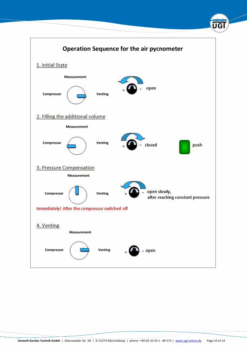
The following procedure is shown schematically in the following figure:
1.Initial State:
The lock valve [7] is closed and the three-way valve *5+ is switched to the “compressor”-position. Both volumes are under atmospheric pressure.
2. Filling the additional volume:
By switching on the compressor the integrated pressure vessel (additional volume VZ) is filled with compressed air. As control variable a pressure of 3 bar is specified. Reaching this pressure the compressor switches off automatically. After reaching this pressure the three-way valve [5] has to be switched to the “Measuring”-position immediately to separate the compressor from the system and hence to avoid a loss of pressure through the compressor. When the pressure in the additional volume is leveled out to a constant value (ca. 2 min.) the pressure has to be logged as initial pressure pA. The value can be taken over to the second line of the display as maximum value by pressing the “Select”-button and then the “Enter”-button.
3. Pressure Compensation:
Now the lock valve [7] has to be opened slowly. The measuring gas (compressed air) flows from the additional volume into the measurement chamber. A fast expansion would lead to a cooling of the gas and breach the test condition of an isothermal change of state (p*V=const.). The reading of the equilibrium pressure pE is done after reaching the equilibrium, thus by constancy of pressure.
Important for step 2 and 3: The criterion for constancy of pressure (maximum pressure variation per time step) has to be defined before the analysis.
4. Venting:
Before opening the measurement chamber after logging the equilibrium pressure it has to be vented. For venting the three-way valve *5+ has to be switched to the “Venting”-position while the lock valve [7] is still open. The measurement chamber and the additional volume chamber are now under atmospheric pressure.
The air in the pipe from the compressor to the three-way valve [5] has not been expanded since finishing step “2. Filling the additional volume”. The compressor is ready for further fillings. After finishing all measurements the compressor has to be vented by switching the three-way valve from “Compressor” to “Venting” several times.
Umwelt-Geräte-Technik GmbH | Eberswalder Str. 58 | D-15374 Müncheberg | phone: +49 (0) 33 43 2 - 89 575 | www.ugt-online.de Page 10 of 14
Operation Sequence for the air pycnometer
Measurement
Measurement
Measurement
Compressor
Compressor
Compressor
Venting
Venting
Venting
Measurement
Compressor Venting
Umwelt-Geräte-Technik GmbH | Eberswalder Str. 58 | D-15374 Müncheberg | phone: +49 (0) 33 43 2 - 89 575 | www.ugt-online.de Page 11 of 14
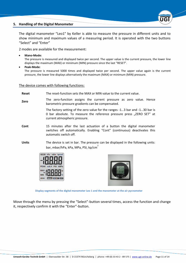
5. Handling of the Digital Manometer
The digital manometer “Leo1” by Keller is able to measure the pressure in different units and to show minimum and maximum values of a measuring period. It is operated with the two buttons “Select” and “Enter”
2 modes are available for the measurement:
Mano-Mode: The pressure is measured and displayed twice per second. The upper value is the current pressure, the lower line displays the maximum (MAX) or minimum (MIN) pressure since the last “RESET”.
Peak-Mode: The pressure is measured 5000 times and displayed twice per second. The upper value again is the current pressure, the lower line displays alternatively the maximum (MAX) or minimum (MIN) pressure.
The device comes with following functions:
Reset The reset-function sets the MAX or MIN value to the current value.
Zero The zero-function assigns the current pressure as zero value. Hence barometric pressure gradients can be compensated.
The factory setting of the zero value for the ranges -1…3 bar and -1…30 bar is 0 bar absolute. To measure the reference pressure press „ZERO SET” at current atmospheric pressure.
Cont 15 minutes after the last actuation of a button the digital manometer switches off automatically. Enabling “Cont” (continuous) deactivates this automatic switch off.
Units The device is set in bar. The pressure can be displayed in the following units:
bar, mbar/hPa, kPa, MPa, PSI, kp/cm2
Display segments of the digital manometer Leo 1 and the manometer at the air pycnometer
Move through the menu by pressing the “Select”-button several times, access the function and change it, respectively confirm it with the “Enter”-button.

Umwelt-Geräte-Technik GmbH | Eberswalder Str. 58 | D-15374 Müncheberg | phone: +49 (0) 33 43 2 - 89 575 | www.ugt-online.de Page 12 of 14
6. Evaluation
6.1. Using the Excel-file “Evaluation Air Pycnometer”
For a fast and easy evaluation of the calibration and measurement an Excel-file is already available on the enclosed USB flash drive. Based on entered measurement values the file calculates the pore volume, the solids volume, the particle density, and the bulk density of the soil sample.
Use the worksheet “measurement protocol” to insert calibration and measurement data as well as
further metadata of the experiment. The worksheets “evaluation calibration” and “evaluation
measurement” automatically evaluate the calibration and measurement, respectively.
In the worksheet “measurement protocol” the values of pA,1 and pE,1 as well as pA,2 and pE,2 have to
be inserted into the columns B and C; and E and F, respectively. The ambient air pressure has to
be inserted into the second line. The relevant units have to be taken into account.
The relation between pA,1 and pE,1 as well as pA,2 and pE,2 is automatically displayed in diagrams. The diagrams allow identifying incorrect values. The relation between pA and pE should be linear. Values that are off from this relation should not be considered within the evaluation process and thus should be removed.
The values of pA and pE of the measurement with the soil sample in the measurement chamber
have to be inserted into the columns H and I. An additional diagram allows identifying incorrect
values. The ambient air pressure during the measurement has to be inserted into the second line.
The metadata table requires the entry of further information. The volume VK which was used
during calibration has to be inserted.
In case small soil samples are investigated it is sometimes useful to reduce the volume of the
measurement chamber by inserting an additional solid volume. This solid volume has to stay in the
measurement chamber throughout the measurements. For evaluation of the measurement this
volume has to be inserted into the metadata-table. In case no extra volume is used the value has to
be set to 0. Sometimes it is useful to reduce the volume of the measurement chamber right from
the beginning of the calibration (when small sample sizes are analyzed). Then the additional solid
volume stays in the measurement chamber throughout the whole measurement procedure,
calibration and measurement. In this case the value of the solid volume is not to insert into the
table.
Further the dimensions of the soil sample have to be inserted. In case a sample ring is used the
outer diameter and the inner diameter of the soil sample have to be inserted. In case the sample is
hand filled into the measurement chamber the diameter of the hand filled sample has to be
inserted instead of the outer diameter. In that case the inner diameter has to be set to 0. In both
cases the height of the sample has to be inserted. At last the value of the dry mass has to be
inserted.

Umwelt-Geräte-Technik GmbH | Eberswalder Str. 58 | D-15374 Müncheberg | phone: +49 (0) 33 43 2 - 89 575 | www.ugt-online.de Page 13 of 14
The worksheet “evaluation calibration” calculates the volumes VZ and VK based on the entries in
the measurement protocol and calculates the corresponding mean value. The worksheet
“evaluation measurement” automatically evaluates the solids volume, the pore volume, and the
particle density for each entry in the measurement protocol as well as the bulk density of the
sample.
6.2. Errors and Advices for effective Measurements
If the sample contains enclosed pores, the gas pycnometric density value is smaller than the real density. In this case it is advisable to break up the sample to a fineness where all pores are destroyed
Gases or vapors (e.g. water vapor) discharged during the measurement can affect the
equilibrium pressure. Indications are long setting-times and a steadily sinking pressure.
To assure constant temperatures the measurements should take place in a constant-temperature room.
If the lock valve was not closed at the beginning of step “2. Filling the Additional Volume” the
measurement chamber has to be vented, before the measurement can be accomplished. If the pressure does not get to a constant value shortly at step “3 Pressure Compensation” the
system is not airtight anymore. Check the sealing ring for damages or debris. Even a single grain of sand might lead to that problem. Hence, make sure to always cover the sealing ring if the measurement chamber is open.
Umwelt-Geräte-Technik GmbH | Eberswalder Str. 58 | D-15374 Müncheberg | phone: +49 (0) 33 43 2 - 89 575 | www.ugt-online.de Page 14 of 14