operating manual - orientalmotor.com · refer to “troubleshooting” if the motor or driver is...
TRANSCRIPT
1
OPERATING MANUAL
2 Phase Stepping Motor Units
UMK Series●Standard Type
UMK24□AA UMK24□ BAUMK26□AA UMK26□ BA
●High Resolution TypeUMK24□MAA UMK24□MBAUMK26□MAA UMK26□MBA
HP-7413-2
Table of Contents
Precautions ........................................................ Page 2
Package Contents .............................................. Page 3
Names and Functions of Driver Parts ................ Page 4
Mounting the Motor ............................................ Page 6
Mounting the Driver ............................................ Page 8
Function Switches .............................................. Page 10
Input / Output Signals ........................................ Page 11
Connections ....................................................... Page 16
Adjusting the Driver Output Current ................... Page 18
Troubleshooting ................................................. Page 20
Specifications ..................................................... Page 22
Dimensions ......................................................... Page 26
Copyright ORIENTAL MOTOR CO., LTD. 1999c
Thank you for purchasing ORIENTAL MOTOR products.Please read this operating manual thoroughly before installing and operating products,and always keep the manual where it is readily accessible.

2
Precautions
Precautions for Installation● Do not use in a place where there is flammable gas and / or corrosive gas.● Products for use only in equipment of protection class IIIII.● The motor and the driver must be properly grounded.●When installing the motor into your equipment, ensure that the motor lead wires are fixed and do not move.
In addition, do not apply any pressure to these lead wires.● Installation must be performed by a qualified installer.
Precautions for Operation● Always turn off the power to the driver before conducting checks or performing work on the product.● The enclosure temperature of this motor and driver may exceed 70℃(158°F) (depending on operation conditions).
In case product is accessible during operation, please attach the following warning label so that it is clearly visible.
Precautions for Troubleshooting● Refer to “Troubleshooting” if the motor or driver is not functioning properly. If the problem can not be corrected,
contact your nearest ORIENTAL MOTOR office as indicated at the back of this manual. Do not disassemble the motor ordriver.
● The driver incorporates double-pole/neutral fusing for the power input. If the driver POWER LED is off, it is possible that onlythe fuse is tripped. High voltage supplied on the hot side may cause electric shock. Turn the power off immediately andrequest service.
Warning label
3
Package Contents
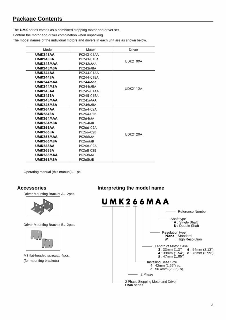
The UMK series comes as a combined stepping motor and driver set.Confirm the motor and driver combination when unpacking.The model names of the individual motors and drivers in each unit are as shown below.
Model DriverUMK243AAUMK243BAUMK243MAAUMK243MBAUMK244AAUMK244BAUMK244MAAUMK244MBAUMK245AAUMK245BAUMK245MAAUMK245MBAUMK264AAUMK264BAUMK264MAAUMK264MBAUMK266AAUMK266BAUMK266MAAUMK266MBAUMK268AAUMK268BAUMK268MAAUMK268MBA
UDK2109A
UDK2112A
UDK2120A
MotorPK243-01AAPK243-01BAPK243MAAPK243MBAPK244-01AAPK244-01BAPK244MAAPK244MBAPK245-01AAPK245-01BAPK245MAAPK245MBAPK264-02APK264-02BPK264MAPK264MBPK266-02APK266-02BPK266MAPK266MBPK268-02APK268-02BPK268MAPK268MB
Operating manual (this manual)…1pc.
AccessoriesDriver Mounting Bracket A…2pcs.
Driver Mounting Bracket B…2pcs.
M3 flat-headed screws…4pcs.(for mounting brackets)
Interpreting the model name
Length of Motor Case3 : 33mm (1.3”) 6 : 54mm (2.13”)4 : 39mm (1.54”) 8 : 76mm (2.99”)5 : 47mm (1.85”)
Shaft typeA : Single ShaftB : Double Shaft
U M K 2 6 6 M A AU M K 2 6 6 M A AU M K 2 6 6 M A AU M K 2 6 6 M A AU M K 2 6 6 M A A
Installing Base Size4 : 42mm (1.65”) sq.6 : 56.4mm (2.22”) sq.
2 Phase
2 Phase Stepping Motor and DriverUMK series
Reference Number
Resolution typeNone : StandardM : High Resolution
4
Names and Functions of Driver Parts
TIMING
TIMING
2-PHASEDRIVERUDK2120A +�
-�
+�
-�
+�
-�
MO
TO
R
⑫
⑮�
⑬���⑭�
⑯�
①�
②�
③�
CW/ PLS
CCW/ DIR.
POWER
C.OFF
CW/ PLS
CCW/ DIR.
O.H.
O.HEAT
COM
YELLOWWHITE
AC100 / 115V
BLACK
RED
GREEN
BLUE
ONON
F2P
N.O.
ACDACOH1PN.C.
C.OFF
FG
RUN
STOP
⑪�
④�
⑨�
⑩�
⑥�
⑱�
⑳�⑲�
⑦�
⑧�
⑤�
21
⑰�
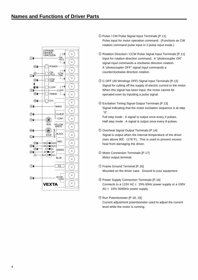
① Pulse / CW Pulse Signal Input Terminals [P.11]Pulse input for motor operation command. (Functions as CWrotation command pulse input in 2-pulse input mode.)
② Rotation Direction / CCW Pulse Signal Input Terminals [P.11]Input for rotation direction command. A “photocoupler ON”signal input commands a clockwise direction rotation.A “photocoupler OFF” signal input commands acounterclockwise direction rotation.
③ C.OFF (All Windings OFF) Signal Input Terminals [P.12]Signal for cutting off the supply of electric current to the motor.When this signal has been input, the motor cannot beoperated even by inputting a pulse signal.
④ Excitation Timing Signal Output Terminals [P.13]Signal indicating that the motor excitation sequence is at step “0”.Full step mode : A signal is output once every 4 pulses.Half step mode : A signal is output once every 8 pulses.
⑤ Overheat Signal Output Terminals [P.14]Signal is output when the internal temperature of the driverrises above 80℃ (176°F). This is used to prevent excessheat from damaging the driver.
⑥ Motor Connection Terminals [P.17]Motor output terminal.
⑦ Frame Ground Terminal [P.16]Mounted on the driver case. Ground to your equipment.
⑧ Power Supply Connection Terminals [P.16]Connects to a 115V AC± 15% 60Hz power supply or a 100VAC± 15% 50/60Hz power supply.
⑨ Run Potentiometer [P.18, 19]Current adjustment potentiometer used to adjust the currentlevel while the motor is running.

5
⑩ Stop Potentiometer [P.18, 19]The current value on the stop potentiometer is active when the motor is at standstill (no pulse is input).
⑪ Power Source Input IndicatorIndicates that the power is turned on.
⑫ CW / PLS Input IndicatorUnder the 1-pulse input mode, lights when a pulse has been received. (Under the 2-pulse input mode, lights when a CW pulsehas been received at the CW / PLS terminals.)
⑬ CCW / DIR Input IndicatorUnder the 1-pulse input mode, lights when a CW signal has been received. (Under the 2-pulse input mode, lights when aCCW pulse has been received at the CCW / DIR. terminals.)
⑭ C. OFF (All Windings Off) Input IndicatorLights when an all windings off signal has been received at the C.OFF terminals.
⑮ Excitation Timing Output IndicatorLights when an excitation timing output signal has been output from TIMING terminals.
⑯ Overheat Output IndicatorLights when the overheat protection function is activated, and an overheat signal has been output from O.H terminals.
⑰ Automatic Current Cutback Select Switch [P.10]Set to ON to decrease the output current to the motor when it is at rest resulting in lower heat generation and lower torque.
⑱ All Windings Off Select Switch (ON / ACO) [P.10]Set to ON mode to cut the current to the motor if the overheat protection function is activated.
⑲ Step Angle Select Switch (F / H) [P.10]Switch for selecting motor step angle.
F : Full Step 1.8°/ step for Standard type0.9°/ step for High Resolution type
H : Half Step 0.9°/ step for Standard type0.45°/ step for High Resolution type
⑳ Pulse Input Mode Select Switch (2P/1P) [P.10]Switch for selecting between 1-pulse input mode, in which control is performed with a pulse signal and a direction signal, and2-pulse input mode, in which control is performed with two systems of pulse signals (CW pulse and CCW pulse).
Overheat Output Logic Select Switch [P.10]Set to N.O. (Normal Open) so that photocoupler turns ON when the overheat signal is output. To reverse the logic, set toN.C. (Normal Close).
21

6
Mounting the Motor
Important
In order to prevent damage to the motor, mount the motor in a place that meets the following conditions.· Indoors· Ambient temperature : -10℃~ +50℃ (+14°F~ +122°F) (where it won’t freeze)· Ambient humidity : 85% or less (where there is no condensation)· Good ventilation· No exposure in direct sunlight· Free from corrosive / flammable gas and dust· No exposure to water or oil (The motor is not waterproof. If there is a chance of it being exposed to liquid, provide a cover.)· Not subject to continuous vibration
· Mount the motor and driver before connecting the motor, driver, and controller together.· Install the motor so that it is securely fastened to a metal surface that is a good thermal conductor, such as steel or
aluminum.
Mounting Location
Mounting Direction and Method· There are no restrictions on the direction of mounting, but motors are usually mounted sideways. They can also be mounted
facing up or down.· Fix the motor firmly. If motor drops, it may damage the air gap between the rotor and the stator, and cause the rotor not be
turned.· Mount the motor tightly against a metal surface with good thermal conductivity. Mounting brackets are available as an
optional parts for easy mounting or fixing of the motor. Suitable mounting bracket for UMK series PK26□ (M) type :PAL2P-2.
Connecting the Motor to the Machine (load)When connecting the motor shaft to the machine being, it must be centered to the load.Inadequate alignment will cause vibration and can drastically shorten the life of the motor’s ball bearings, resulting in fatiguefailure of the motor shaft. Use a flexible coupling to connect the motor shaft to the machine being used (load).
Notes· Support the motor shaft when attaching a coupling, timing pulley, or other device to the shaft. Make sure that there is no thrust
or overhung loads between the shaft and motor and avoid shock loading. Such loads or shock could damage the equipmentor the motor.
· The air gap between the rotor and stator inside the motor is extremely small. Therefore, do not subject the motor shaft to anyshocks. Shocks will cause the rotor and stator to rub against each other. This can also damage the shaft bearings.
Flexible Coupling Ball Screw
Stepping Motor
�

7
Mounting Plate Dimensions unit : mm (inch)
UMK24 □□□□□ (M)
X
φ3.5(0.14)-4holes
φ5.5(0.22)min.
spot facing or through hole
R0.3(0.01)max.
X'
31±0.1(1.22±0.004)
31±
0.1(
1.22±
0.00
4)
shaft hole
φ22+0.0210 (0.87 )+0.0008
0
2.5(0.1)min.
3(0.12)min.
φ4.5(0.18)-4holes
φ7(0.28)min.
spot facing or through hole
R0.3(0.01)max.
X'
47.14±0.35(1.86±0.014)
47.1
4±0.
35(1
.86±
0.01
4)
shaft hole
φ38.1 +0.064+0.025(1.5 ) +0.0025
+0.001
2(0.08)min.
4(0.16)min.
X
X-X'
X-X'
UMK26 □□□□□ (M)

8
Driver Mounting Bracket A Driver Mounting Bracket B
Notes· Fix the drivers to a metal plate at least 2 mm (0.08”) thick with good heat-conduction such as aluminum or steel.· When mounting the driver directly to the machine without using the mounting bracket provided with the product, pay
attention to length of mounting screws. Use the screws to extend 2~3.5 mm (0.08”~0.14”) into the driver. Screws thatare longer than necessary length may cause bad insulation.
· When the overheat signal output indicator lights, an overheat signal is output, cool the driver using cooling fan.
Mounting the Driver
Mounting LocationMount the driver in a place that meets the following conditions.· Indoors· Ambient temperature : 0℃~ +40℃ (+32°F~ +104°F) (where it won’t freeze) (When the ambient temperature exceeds
40℃ (104°F), use a fan to cool the driver, as overheating could damage the driver’s components.)· Ambient humidity : 85% or less non condensing· Free from corrosive / flammable gas and dust· No exposure to water or oil· No exposure in direct sunlight· Mount driver so that there is at least 25 mm (0.98”) between each side of the driver and any other equipment or structural
components.· When mounting the driver in an airtight location, such as a control panel, or near to heat-generating equipment, be sure to
establish ventilation holes to prevent overheating.· When the driver is mounted close to a source of vibration, install shock absorbers in order to prevent damage to the driver.· When there is a source of significant noise near the driver (high-frequency welding machine, large electromagnetic switch,
etc.), take measures to prevent noise interference, such as inserting a noise filter or connecting the driver to a separatepower supply line.
· Prevent conductive materials (filings, pins, pieces of electric wires, etc.) from adhering to the inside of the driver, as thiscould damage the circuits inside the driver.
Mounting Direction and MethodThe driver is designed to disperse heat through natural convection. When installing the driver, be sure to install only in theposition shown below.
Use mounting bracket “A” when install the driver vertically to the equipment. When install it horizontally to bottom line ofequipment, use mounting bracket “B”.
When Using Multiple DriversWhen using multiple drivers in a series, the heat produced by the drivers will raise the ambient temperature. Leave at least20 mm (0.79”) between drivers to prevent overheating and damage to the drivers.

9
Mounting Dimensions unit : mm (inch)
Using mounting bracket A
Using mounting bracket B
165(
6.5)
150(
5.9)
20(0.79)
35(1.38)
M4(No.8-32UNC)Mounting-4holes
126(4.96)
111(4.37)
35(1
.38)
20(0
.79)
M4(No.8-32UNC)Mounting-3holes
M4(No.8-32UNC)tap
M4(No.8-32UNC) screw
Flat washer
Spring washer
M4(No.8-32UNC)tap
NoteThe screw can notbe used in this slit.
NoteThe screw can notbe used in this slit.
Flat washer
M4(No.8-32UNC)screw
Spring washer
Bottom face mounting Upper face mounting

10
Function SwitchesThe following function select switches are used to change the driver’s factory settings. (The factory settings are as indicated in thefollowing diagram.)
Automatic Current Cutback at motor standstill (ON / ACD)When switch is flipped to “ON” , the automatic current reduction (current cutback) at motor standstill function isset. Approximately 0.1 seconds after pulses cease, the motor output current is automatically lowered tosuppress heat generation in the motor and driver. {The rate of current reduction (current cutback) is shown inthe paragraph of “Current reduction at motor standstill” on page 18.}Generally , the switch should be at “ON” side. If it is flipped to “ACD”, the automatic current reduction atmotor standstill function is canceled.Notes· When stopping the pulse signal, always set it in the “photocoupler Off” state. Setting it in the “photocoupler ON”
state prevents the automatic current reduction function from working.· Since the holding torque is proportional to output current, holding torque is lowered when current is lowered
(Holding torque is proportional to stop current that is commanded by “STOP” potentiometer)
All Windings Off (ON / ACO)Set automatic current off function flipping this switch to “ON”. When the overheat protection function isactivated (When temperature inside the driver becomes extremely hot) current output to the motor isautomatically stopped and the motor comes to a natural stop.In situation where stopping of the motor due to overheat protection could pose problems, automatic currentoff can be overridden by setting this switch to “ACO”. However, as a rule, whenever the overheat protectionfunction is active (shown by overheat signal on display) the motor should be stopped as soon as possible.
Step Angle (F / H)When step angle switch is flipped to “F” :
Standard type : The driver is set for 1.8 /゚step (200 pulses per revolution).High Resolution type : The driver is set for 0.9 /゚step (400 pulses per revolution).
When the switch is flipped to “H” :Standard type : The driver is set for 0.9 /゚step (400 pulses per revolution).High Resolution type : The driver is set for 0.45 /゚step (800 pulses per revolution).
Pulse Input Mode (2P / 1P)The driver is designed to function under either of the following pulse output mode.When the switch is flipped to “1P”, the driver is set for the 1-pulse input mode, in which a pulse signal and adirection of rotation signal are used to control the motor. When pulse input switch is flipped to “2P”, thedriver is set for the 2-pulse input mode, in which two types of pulse signal (one each for CW and CCW) areused to control the motor.Notes1-Pulse Input Mode
Switch direction of rotation when the pulse signal is stopped (when it is in the “photocoupler Off” state).2-Pulse Input Mode
Do not input CW pulse and CCW pulse signals simultaneously. When either the CW or CCW pulse signalis in the “photocoupler ON” state, the motor will not function properly even if a pulse is input to the othersignal.
Overheat Output Logic (N.O. / N.C.)Overheat Output Logic switch set to “N.O.” : When the overheat signal is output, the photocoupler isswitched on ; during normal operation, photocoupler is off.Overheat Output Logic switch set to “N.C.” : When the overheat signal is output, the photocoupler isswitched off ; during normal operation, photocoupler is on.
�
RED
GREEN
BLUE
ONON
F2P
N.O.
ACDACOH1PN.C.
All Windings Off select switch
Step Angle select switch
Overheat Output Logic select switch
Pulse Input Mode select switch
Automatic Current Cutback select switch
ON
�
ACO
F
�
H
2P
�
1P
N.O.
�
N.C.
ON�
ACD

11
Input / Output Signals
Pulse, Direction (CW, CCW) Input
■■■■■ Input Circuits and Connection ExampleSignals inside parentheses indicate signals in 2-pulse input mode.
When V0 is 5V, external resistance (R) is not needed.When V0 exceeds 5V, connect external resistance (R) andadjust the input current to 20mA or less.
1-Pulse Input ModePulse signal
Pulse signal is input to the CW pulse / pulse signal input terminal.When the photocoupler state changes from “ON” to “OFF”, the motor rotates one step.The direction of rotation is determined by the following rotation direction signals.
Rotation direction signalThe rotation direction signal is input to CCW pulse / rotation direction signal input terminal.A “photocoupler ON” signal input commands a clockwise direction rotation.A “photocoupler OFF” signal input commands a counterclockwise direction rotation.
2-Pulse Input ModeCW pulse signal
When the photocoupler state changes from “ON” to “OFF” the motor rotates one step in the clockwise direction.CCW pulse signal
When the photocoupler state changes from “ON” to “OFF” the motor rotates one step in the counterclockwisedirection.
V0
+�
-�
-�
+�
CW/PLS
CCW/DIR.
(R)
(R)
PLS(CW)
CW/CCW(CCW)
220Ω�
220Ω�20mA max.
20mA max.
Controller output
Open collectoroutput
Inside of driver
■■■■■Pulse Waves
· Pulse voltage : Photocoupler OFF = +4 ~ +5V, Photocoupler ON = 0 ~ +0.5V· Input a pulse with a pulse width of 5µs or more, pulse rise / fall time of 2µs or less, and pulse duty of 50% or less.
(Responds up to 25 kHz with a pulse of 50%. When using at a faster speed, reduce the pulse width [shorten the photocouplerON time].)
· When switching from clockwise to counterclockwise direction, an interval of 20µs or more is needed for the circuit response.The time required for motor response varies considerably depending on the load inertia and the pulse rate.
Notes1-Pulse Input ModeSwitch Rotation Direction when the pulse signal is stopped (when it is photocoupler OFF).
2-Pulse Input ModeDo not input CW pulse and CCW pulse signals simultaneously.When either the CW or CCW pulse signal is photocoupler ON, the motor will not function properly even if a pulse is input to the othersignal.
Photocoupler ON
Photocoupler OFF
Photocoupler ON
Photocoupler OFF
PULSE
5μs
※�
5μs
2μs max. 2μs max.
90%10%
DERECTION
20μs
min. min. min.
※ Shaded areas represent when the photocoupler is on. The motor moves when the photocoupler state changes from“ON”to“Off”(arrow).
12
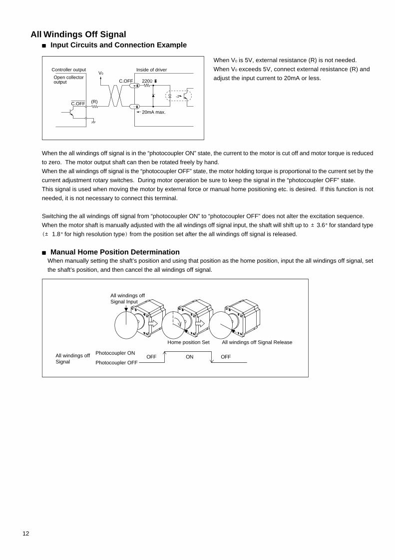
When the all windings off signal is in the “photocoupler ON” state, the current to the motor is cut off and motor torque is reducedto zero. The motor output shaft can then be rotated freely by hand.When the all windings off signal is the “photocoupler OFF” state, the motor holding torque is proportional to the current set by thecurrent adjustment rotary switches. During motor operation be sure to keep the signal in the “photocoupler OFF” state.This signal is used when moving the motor by external force or manual home positioning etc. is desired. If this function is notneeded, it is not necessary to connect this terminal.
Switching the all windings off signal from “photocoupler ON” to “photocoupler OFF” does not alter the excitation sequence.When the motor shaft is manually adjusted with the all windings off signal input, the shaft will shift up to ±3.6°for standard type(± 1.8°for high resolution type) from the position set after the all windings off signal is released.
■■■■■Manual Home Position DeterminationWhen manually setting the shaft’s position and using that position as the home position, input the all windings off signal, setthe shaft’s position, and then cancel the all windings off signal.
All Windings Off Signal■■■■■ Input Circuits and Connection Example
(R)C.OFF
V0
C.OFF+�
220Ω�
20mA max.-�
Controller output
Open collectoroutput
Inside of driver
All windings offSignal Input
Photocoupler ONOFF ON OFF
All windings off Signal ReleaseHome position Set
All windings offSignal Photocoupler OFF
When V0 is 5V, external resistance (R) is not needed.When V0 exceeds 5V, connect external resistance (R) andadjust the input current to 20mA or less.
13
(Step) 3 0 ・・・
3 4 5 61 2
1 0
1 2
PULSE
TIMING OUTPUT
DIRECTION
1 20 1 2
*
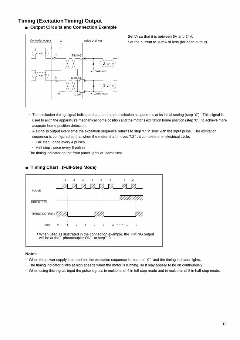
*When used as illustrated in the connection example, the TIMING output will be at the“photocoupler ON”at step“0”.
· The excitation timing signal indicates that the motor’s excitation sequence is at its initial setting (step “0”). This signal isused to align the apparatus’s mechanical home position and the motor’s excitation home position (step “0”), to achieve moreaccurate home position detection.
· A signal is output every time the excitation sequence returns to step “0” in sync with the input pulse. The excitationsequence is configured so that when the motor shaft moves 7.2 ,゚ it complete one electrical cycle.· Full step : once every 4 pulses· Half step : once every 8 pulses
The timing indicator on the front panel lights at same time.
V0
+�
-�
+�
TIMING
O.HEAT
R
R
Controller output Inside of driver
10mA max.
10mA max.COM
Timing (Excitation Timing) Output■■■■■Output Circuits and Connection Example
Set V0 so that it is between 5V and 24V.Set the current to 10mA or less (for each output).
■■■■■Timing Chart : (Full-Step Mode)
Notes· When the power supply is turned on, the excitation sequence is reset to“0”and the timing indicator lights.· The timing indicator blinks at high speeds when the motor is running, so it may appear to be on continuously.· When using this signal, input the pulse signals in multiples of 4 in full-step mode and in multiples of 8 in half-step mode.

14
V0
+�
-�
+�
TIMING
O.HEAT
R
R
Controller output Inside of driver
10mA max.
10mA max.COM
O.HEAT (Overheat) Output■■■■■Output Circuits and Connection Example
Set V0 so that it is between 5V and 24V.Set the current to 10mA or less (for each output).
· The overheat signal is output when the temperature of the driver rise above 80℃ (176 F゚). The overheat indicator onthe front panel lights when this signal is output.
· If the automatic current off function has been set at this time, output current to the motor drops to “0” and the motor comesto a natural stop.
· On the above connecting diagram, the output signal is “photocoupler ON” when the switch is set to “N.O.”. If “photocouplerOFF” signal is required, set the switch to “N.C.”.
· When an overheat signal is output, either reconsider the operating conditions (ambient temperature, operating patterns,etc.) or take other measures such as forced cooling of the driver.
· Overheat signal will be canceled automatically as soon as the inner temperature of the driver drops. (The overheat signalreturns to “photocoupler OFF” state at this time and the overheat indicator on the front panel goes out.)Be aware that the above return/release cannot be controlled by external signals or by restarting the system.
NotesWhen the overheat protection function is activated
Cut the power to the driver and check the conditions (ambient temperature, operation pattern, etc.) ; or, reduce the driver’stemperature by cooling it with a fan, etc.
Possible condition for overheating
· Placement of the driver in a location with insufficient air circulation for proper heat radiation, or when the driver’s internaltemperature becomes high due to high ambient temperatures and the heat generated by the driver.
· Continuous operation of the driver at the pulse rate with the largest current input to the driver. Input to the driver variesconsiderably according to motor size and pulse rate. Achieves its max. Input at 10~ 30kHz. Please refer to the driverinput current ratings in the “speed torque characteristics” section of the catalog.
15
Current reduction(current cutback)
All windings off
1
20μs. min.
5μs min.
CW
Motor
CCW
1-Pulse Mode
Pulse
Rotation direction
All windings off
photocoupler ONphotocoupler OFF
photocoupler ONphotocoupler OFF
photocoupler ONphotocoupler OFF
approximately 100ms.
2
50μs. min.
Current reduction(current cutback)
All windings off
2
3
1
20μs. min.
5μs min.
CW
Motor
CCW
2-Pulse Mode
CW pulse
CCW pulse
All windings off
photocoupler ONphotocoupler OFF
photocoupler ONphotocoupler OFF
photocoupler ONphotocoupler OFF
approximately 100ms.
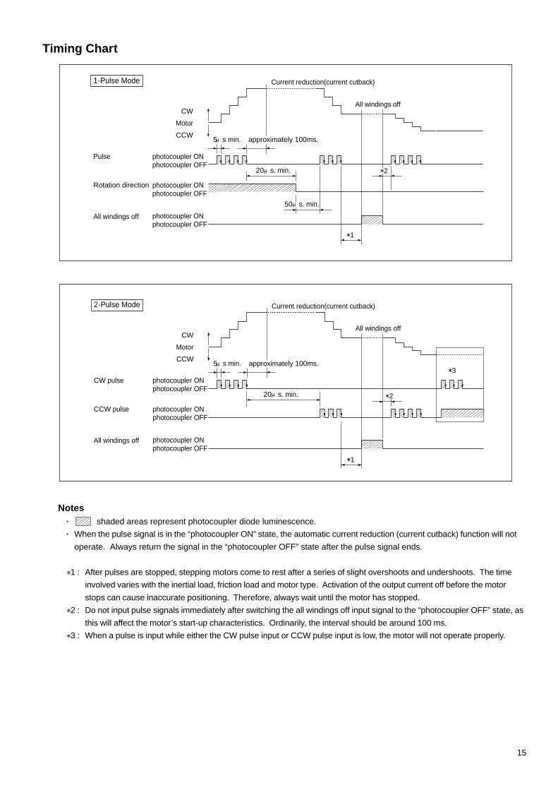
Timing Chart
Notes· shaded areas represent photocoupler diode luminescence.· When the pulse signal is in the “photocoupler ON” state, the automatic current reduction (current cutback) function will not
operate. Always return the signal in the “photocoupler OFF” state after the pulse signal ends.
*1 : After pulses are stopped, stepping motors come to rest after a series of slight overshoots and undershoots. The timeinvolved varies with the inertial load, friction load and motor type. Activation of the output current off before the motorstops can cause inaccurate positioning. Therefore, always wait until the motor has stopped.
*2 : Do not input pulse signals immediately after switching the all windings off input signal to the “photocoupler OFF” state, asthis will affect the motor’s start-up characteristics. Ordinarily, the interval should be around 100 ms.
*3 : When a pulse is input while either the CW pulse input or CCW pulse input is low, the motor will not operate properly.

16
Connections
Power SupplyThe UMKUMKUMKUMKUMK series can be used with either a single-phase 115V 60Hz or single-phase 100V 50/60Hz power supply.The power supply input current is :UMK243 type : 1A max. UMK243M/244M type : 0.7A max.UMK244/245 type : 1.4A max. UMK245M type : 0.8A max.UMK264/266/268 type : 2.2A max. UMK264M/266M/268M type : 1.3A max.Use a power source which is able to provide sufficient input current.(The listed for the power supply input current is the driver’s maximum input current when a load has been applied to the motor.)
FG
Pulse generator Controller etc.
Metal plate
Driver
Make the connectionas short as possible.[Use wire of 0.75mm2
(AWG18) or thicker.]
※� �
Shield line
TIMING
TIMING
2-PHASEDRIVERUDK2120A +�
-�
+�
-�
+�
-�
MO
TO
R
CW/ PLS
CCW/ DIR.
POWER
C.OFF
CW/ PLS
CCW/ DIR.
O.H.
O.HEAT
COM
YELLOWWHITE
AC100 / 115V
BLACK
RED
GREEN
BLUE
ONON
F2P
N.O.
ACDACOH1PN.C.
C.OFF
FG
RUN
STOP
Notes
When the power capacity is insufficient, the following problems may arise due to a drop in the motor’s output.· The motor does not rotate normally during high speed operation (insufficient torque).· The motor starts and stops slowly.
Excitation Timing Output Indicator
When turning on the power, the motor excitation sequence is reset to its original position at step “0” and this indicator isilluminated.
Note
Turning the power back on
After the power has been turned off, wait 5 seconds before turning it back on again. If the power is turned on againimmediately after it has been turned off, the timing indicator will not be illuminated and the motor excitation sequence will notbe reset to step “0”.
Notes
· Use twisted-pair wire of 2m (78.7”) or less in length for the signal lines.· Use wire of 0.5mm2 (AWG20) or thicker for motor lines and power supply lines, and use 0.75mm2 (AWG18) or thicker for the
wire for the ground line.· Signal lines should be kept away at least 10cm (0.39”) from power lines (power supply lines and motor lines). Do not bind
the signal line and power line together.· Use an open collector transistor (sink type) at the controller signal output.
Frame Ground (FG) TerminalFG terminal must be properly grounded to reduce the chance of electrical shock.Ground the FG terminal of the external controller (pulse generator) to same point in order to prevent malfunctions due to externalnoise.(The motor can be grounded to a device using the assembly screws.)· If the noise generated from the motor lead wires should cause a problem, shield the motor lead wires with conductivity tape or
wire mesh.
Indicators Illuminated When Turning on the UnitBefore turning on the unit confirm that there are no mis-wirings in the signal lines, motor and power lines.
Power Source Input Indicator
Normally illuminated when turning on the power.

17
Connection Diagram
Blue
Red
Yellow
Black
Driver
Green
Single phase 100V±15% 50/60Hz orSingle phase 115V±15% 60Hz
White
Grounding(Use wire of 0.75mm2 (AWG18) or more in cross sectional area.)
User's Controller
Overheat Output
Twisted Pair Line
Excitation Timing Output
GND
+5V
+5V
Pulse Input
Rotation Direction Input
All Windings Off InputTIMING
TIMING
2-PHASEDRIVERUDK2120A +�
-�
+�
-�
+�
-�
MO
TO
R
CW/ PLS
CCW/ DIR.
POWER
C.OFF
CW/ PLS
CCW/ DIR.
O.H.
O.HEAT
COM
YELLOWWHITE
AC100 / 115V
BLACK
RED
GREEN
BLUE
ONON
F2P
N.O.
ACDACOH1PN.C.
C.OFF
FG
RUN
STOP
2-phase stepping motor

18
Adjusting the Driver Output Current
The UMK driver is shipped with the motor rated current set to either 0.95 / 1.2 / 2A / phase depending on the driver model {andthe standstill current reduction (current cutback) ratio set to approximately 40%}. It is not necessary to adjust the currentunder normal operating conditions. However, readjust the current setting in the following cases.· When you want to prevent the motor and driver from becoming too hot Lower the motor’s running current and standstill
current· When there is slack in terms of torque and you want to prevent vibration Lower the motor’s running current· When you want to increase the motor’s standstill holding torque Raise the motor’s standstill current
Notes
· Since the torque is proportional to current, when lowering the current be careful not to lower it too much.· Raising the motor’s standstill current increases the magnitude of the motor and driver’s temperature rise.· Do not set the motor’s running current above the rated current, since doing so could damage both driver and motor.· The current reduction ratio varies depending on the motor running current setting, as indicated below.
The relationship between the potentiometers and the current setting is shown in this diagram.
Holding torque can be calculated using the following formulas. (Holding torque is proportional to output current.)
UMK243(M) Motor running current Motor standstill current
UMK244(M), 245(M)
UMK26□ (M)
Maximum holding torque (oz · in) × Current reduction ratio (%)
100· Holding torque (oz · in) =
· Current reduction (current down) ratio (%) =Running current settingStandstill current setting
× 100
Factory setting(0.95A/phase)
Out
put c
urre
nt(A
/ ph
ase)
(Representative values)
0.5
0.95
00 21 3 4 5 6 7 8 9 10
RUN potentiometer scale
0.25
0.75
0 21 3 4 5 6 7 8 9 10
STOP potentiometer scale
(Representative values)
30
50
70
90
10
20
40
60
80
Factory setting(40%)
0.95A setting
100
0.3A setting
0.5A settingD
own
ratio
(%
)
0.5
1.2
00 21 3 4 5 6 7 8 9 10
1
0.75
Factory setting(1.2A/phase)
(Representative values)
RUN potentiometer scale
0.25
Out
put c
urre
nt(A
/ ph
ase)
30
50
70
90
10
20
40
60
80
100
STOP potentiometer scale
(Representative values)
Factory setting(40%)
1.2A setting
0.3A setting
0.6A setting
0 21 3 4 5 6 7 8 9 10
Dow
n ra
tio (
%)
0.5
1
1.5
2
0
Factory setting(2A/phase)
(Representative values)
RUN potentiometer scale
0 21 3 4 5 6 7 8 9 10
Out
put c
urre
nt(A
/ ph
ase)
30
50
70
90
10
20
40
60
80
100
STOP potentiometer scale
(Representative values)
Factory setting(40%)
2A setting
0.5A setting
1A setting
0 21 3 4 5 6 7 8 9 10
Dow
n ra
tio (
%)

19
Blue
Red
YellowBlack
Green
WhiteStepping motor
TIMING
TIMING
2-PHASEDRIVERUDK2120A +�
-�
+�
-�
+�
-�
MO
TO
R
CW/ PLS
CCW/ DIR.
POWER
C.OFF
CW/ PLS
CCW/ DIR.
O.H.
O.HEAT
COM
YELLOWWHITE
AC100 / 115V
BLACK
RED
GREEN
BLUE
ONON
F2P
N.O.
ACDACOH1PN.C.
C.OFF
FG
RUN
STOP
-+
AC power supply
DC ammeter
RUN PotentiometerUsed to adjust the motor's running current
STOP PotentiometerUsed to adjust the current cutback ratioat motor standstill
Automatic Current Cutback switchSet according to the explanation below
Set Angle select switchSet to "F"
Adjusting the Current Using an Ammeter
When more precise current adjustments are necessary, make them by connecting an ammeter between the driver and motor, asshown in the diagram below.
Note
With the connection shown here, the current flowing to the ammeter is twice that of a single phase.Therefore, the current setting (per single phase) is equivalent to half the value indicated on the ammeter.For example, when the ammeter indicates 0.5A, the setting is 0.25A / phase.
Note
Inputting pulses input changes the value ; therefore, perform the setting without any input other than what designated.
Setting the Motor Running Current(1) Switch automatic current reduction to “ACD”.
(2) After connecting the motor and DC ammeter, turn the power on.(3) Set the current using the RUN potentiometer.
· Set the value indicated on the ammeter to twice the desired current setting (per phase).(4) Turn the automatic current reduction switch back to “ON”.(5) Set the step angle select switch back to desired position.
Setting the Motor Standstill Current(1) Switch automatic current reduction to “ON”.
(2) After connecting the motor and DC ammeter, turn the power on.(3) Set using the STOP potentiometer.
· Set the value indicated on the ammeter to twice the desired current setting (per phase).· The standstill current is set at the factory to approximately 40% of the running current.
(4) Turn the automatic current reduction switch back to “ON”.(5) Set the step angle select switch back to desired position.
F
�ACD
F
�ON
Note
To suppress heat generation, always keep the automatic current reduction switch on (except when setting the current).

20
TroubleshootingWhen your stepping motor is not operating properly, identify the problem using the table below and then take the measuresdescribed therein.If that does not solve the problem, inquire at your nearest sales office.
Notes· Do not take the motor apart. The motor may not perform as indicated in the specifications after reassembling.
Problem
The motor doesn’t haveany holding torque.(The shaft can be easilyturned by hand.)
The motor doesn’t move.
The motor doesn’t moveeven after a pulsesignal is input.
The motor rotates in theopposite direction asthe CW / CCW pulsesignal (or directionsignal).
Things to Check(1)Is the driver’s power indicator on?
(It should be on.)(2)Is the driver’s C.OFF indicator off?
(It should be off.)
(3)Is the driver’s O.H. indicator off?(It should off.)
(4)Have the driver, motor and powersupply been connected correctly andsecurely?
(5)Have the driver’s RUN and STOPpotentiometers been turned down toofar?
(6)After input of the pulse signal, are thedriver’s CW / PLS or CCW / DIR.indicators illuminated?
(7)When using the 1-pulse input mode(when the pulse input switch is set to“1P”), has the pulse signal beenmiswired to the CCW / DIR. terminal?
(8)When using the 2-pulse input mode(when the pulse input switch is set to“2P”), are the CW / PLS and CCW /DIR. indicators illuminatedsimultaneously?
(9)When using the 1-pulse input mode(when the pulse input mode switch isset to “1P”), input a pulse signal to theCW / PLS terminal without making anyconnections to the CCW / DIR.terminal.
(10)When using the 2-pulse input mode(when the pulse input mode switch isset to “2P”), have the CW / PLS andCCW / DIR. pulse signals beenconnected in reverse?
Possible Solution· If it is not on, check the power connection voltage, and then
recheck to see if the power indicator is on.· When the all windings off signal has been input, the C.OFF
indicator is illuminated and the motor ceases to be excited(has no holding torque).
· The O.H. indicator is illuminated when the driver’s overheatprotection function has been activated (see page 14).When the automatic current off function switch is in the“ACO” position, the motor ceases to be excited (has noholding torque).
· Check the wiring configuration. If the lead wires have beenextended, check the connection.
· The problem lies in the potentiometer for adjusting theoutput current to the motor (see pages 18 and 19). If it isturned down too far, turn it back to the factory setting andthen recheck.
· If neither the CW / PLS nor the CCW / DIR. indicators areilluminated, check the connections and the pulse signal’svoltage and waveform (see page 11).
· Connect the pulse signal to the CW / PLS terminal.
· When a pulse is being input, the motor will not operate if theother pulse input terminal is already in the “photocouplerON” state. Be sure to set the other terminal to the“photocoupler OFF” state.
· If the motor then rotates in the CCW / DIR. the motor anddriver are functioning properly. Check the level of therotation direction signal once again. (The correctconfiguration is “photocoupler ON” = CW / PLS,“photocoupler OFF” = CCW / DIR.).
· Connect the CW pulse to the CW / PLS terminal and theCCW pulse to the CCW / DIR. terminal.
If the motor fails to return to normal even after checking all of the above, the problem could be that thedriver is damaged. If that appears to be the case, have the unit repaired after checking the power supplyvoltage and connections once again.· Begin by checking items (1), (2), (3), (4) and (5).

21
ProblemThe motor isn’toperating properly.
Start-up is irregular.
The motor doesn’t moveenough.The motor moves toomuch.
The motor losessynchronism duringacceleration(or operation).
There is too muchvibration.
The motor is too hot.[temperature of themotor case must beless than 100℃(212°F)? ]
The automatic currentcutback function doesn’twork.
Things to Check
(11)In 2-pulse input mode (pulse inputmode select switch set to 2P) : Arethe driver’s CW / PLS indicator andCCW / DIR. line both illuminated atthe same time?
(12)Are the motor and load accuratelycentered? Is the load too large?
(13)Is the actual motor step angle thesame as the motor step anglerequired by the device? (Full / Halfstep)
(14)Is the number of pulses sent to thedriver what you expect? Check yourcontroller gettings.
(15)Begin by checking item (3).(16)Is the start pulse rate too high?(17)Is the acceleration time too short?(18)Is external noise having an effect?
(19)There may be excessive torque.(20)Try changing the pulse rate.
(21)The motor is running too long.(22)Is the automatic current cutback
function turned off?(23)Try changing the pulse rate.
(24)Is the pulse indicator OFF after thepulse signals are complete?
(25)Is the automatic current reduction(current cutback) function turned off?
Possible Solution
· The motor will run irregularly if two pulses are input at thesame time.
· Reduce the load on the motor at start-up by aligning themotor and load shaft centers, reducing statical friction load,etc.
· Check the driver’s step-angle-select switch setting.
· Check the setting on the controller.
· Reduce it, and then check.· Extend it, and then check.· Turn off any devices thought to be possible sources of
noise, and check the motor when it is operating alone.· Try lowering the motor’s running current.· If changing the pulse rate reduces vibration, the source may
be motor resonance. Try changing the pulse rate or thestep angle.
· Try installing a clean damper (double-shaft motors only).· Shorten running time or extend break time.· Set the current reduction (current cutback) switch on the
driver to ON.· The motor’s temperature rise varies depending on the pulse
rate. Refer to the speed-torque characteristics in thecatalog, and operate at a lower input speed.
· Do not let the motor case get hotter than 100℃ (212°F).· This function doesn’t work, and the motor current is not
reduced, when the pulse signal is held at the “photocouplerON”. Always return it to the “photocoupler OFF”.
· Set the current reduction (current cutback) switch on thedriver to ON.
· Begin by checking items (4), (5), and (6).
22
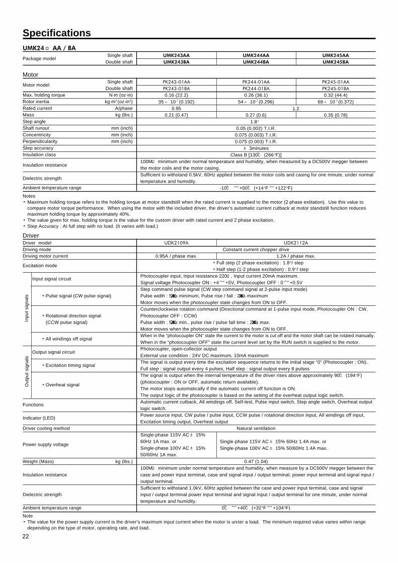
SpecificationsUMK24□AA / BA
Package modelSingle shaft
Double shaftUMK245AAUMK245BA
UMK244AAUMK244BA
UMK243AAUMK243BA
MotorMotor model
Single shaftDouble shaft
Max. holding torque N·m (oz·in)Rotor inertia kg·m2 (oz·in2)Rated current A/phaseMass kg (lbs.)Step angleShaft runout mm (inch)Concentricity mm (inch)Perpendicularity mm (inch)Step accuracyInsulation class
Insulation resistance
Dielectric strength
Ambient temperature range
PK245-01AAPK245-01BA0.32 (44.4)
68× 10-7 (0.372)
0.35 (0.78)
PK244-01AAPK244-01BA0.26 (36.1)
54× 10-7 (0.296)
0.27 (0.6)
PK243-01AAPK243-01BA0.16 (22.2)
35× 10-7 (0.192)0.95
0.21 (0.47)1.8°
0.05 (0.002) T.I.R.0.075 (0.003) T.I.R.0.075 (0.003) T.I.R.± 3minutes
Class B [130℃ (266°F)]100MΩ minimum under normal temperature and humidity, when measured by a DC500V megger betweenthe motor coils and the motor casing.Sufficient to withstand 0.5kV, 60Hz applied between the motor coils and casing for one minute, under normaltemperature and humidity.
-10℃ ~ +50℃ (+14°F~ +122°F)
1.2
Notes・Maximum holding torque refers to the holding torque at motor standstill when the rated current is supplied to the motor (2 phase extitation). Use this value to
compare motor torque performance. When using the motor with the included driver, the driver’s automatic current cutback at motor standstill function reducesmaximum holding torque by approximately 40%.
・The value given for max. holding torque is the value for the custom driver with rated current and 2 phase excitation.・Step Accuracy : At full step with no load. (It varies with load.)
Note・The value for the power supply current is the driver’s maximum input current when the motor is under a load. The minimum required value varies within range
depending on the type of motor, operating rate, and load.
Single-phase 115V AC± 15% 60Hz 1.4A max. orSingle-phase 100V AC± 15% 50/60Hz 1.4A max.
DriverDriver modelDriving modeDriving motor current
Excitation mode
Input signal circuit
・Pulse signal (CW pulse signal)
・Rotational direction signal (CCW pulse signal)
・All windings off signal
Output signal circuit
・Excitation timing signal
・Overheat signal
Functions
Indicator (LED)
Driver cooling method
Power supply voltage
Weight (Mass) kg (lbs.)
Insulation resistance
Dielectric strength
Ambient temperature range
UDK2112A
1.2A / phase max.
UDK2109A
0.95A / phase max.Constant current chopper drive
・Full step (2 phase excitation) : 1.8°/ step・Half step (1-2 phase excitation) : 0.9°/ step
Photocoupler input, Input resistance 220Ω, Input current 20mA maximum.Signal voltage Photocoupler ON : +4~ +5V, Photocoupler OFF : 0~ +0.5VStep command pulse signal (CW step command signal at 2-pulse input mode)Pulse width : 5μμμμμs minimum, Pulse rise / fall : 2μμμμμs maximumMotor moves when the photocoupler state changes from ON to OFF.Counterclockwise rotation command (Directional command at 1-pulse input mode, Photocoupler ON : CW,Photocoupler OFF : CCW)Pulse width : 5μμμμμs min., pulse rise / pulse fall time : 2μμμμμs max.Motor moves when the photocoupler state changes from ON to OFF.When in the “photocoupler ON” state the current to the motor is cut off and the motor shaft can be rotated manually.When in the “photocoupler OFF” state the current level set by the RUN switch is supplied to the motor.Photocoupler, open-collector outputExternal use condition : 24V DC maximum, 10mA maximumThe signal is output every time the excitation sequence returns to the initial stage “0” (Photocoupler : ON).Full step : signal output every 4 pulses, Half step : signal output every 8 pulsesThe signal is output when the internal temperature of the driver rises above approximately 90℃ (194°F)(photocoupler : ON or OFF, automatic return available).The motor stops automatically if the automatic current off function is ON.The output logic of the photocoupler is based on the setting of the overheat output logic switch.Automatic current cutback, All windings off, Self-test, Pulse input switch, Step angle switch, Overheat outputlogic switch.Power source input, CW pulse / pulse input, CCW pulse / rotational direction input, All windings off input,Excitation timing output, Overheat output
Natural ventilation
0.47 (1.04)100MΩ minimum under normal temperature and humidity, when measure by a DC500V megger between thecase and power input terminal, case and signal input / output terminal, power input terminal and signal input /output terminal.Sufficient to withstand 1.0kV, 60Hz applied between the case and power input terminal, case and signalinput / output terminal power input terminal and signal input / output terminal for one minute, under normaltemperature and humidity.
0℃ ~ +40℃ (+32°F~ +104°F)
Single-phase 115V AC± 15%60Hz 1A max. orSingle-phase 100V AC± 15%50/60Hz 1A max.
Out
put s
igna
lsIn
put s
igna
ls

23
UMK26□AA / BA
Package modelSingle shaft
Double shaftUMK268AAUMK268BA
UMK266AAUMK266BA
UMK264AAUMK264BA
MotorMotor model
Single shaftDouble shaft
Max. holding torque N·m (oz·in)Rotor inertia kg·m2 (oz·in2)Rated current A/phaseMass kg (lbs.)Step angleShaft runout mm (inch)Concentricity mm (inch)Perpendicularity mm (inch)Step accuracyInsulation class
Insulation resistance
Dielectric strength
Ambient temperature range
PK268-02AAPK268-02BA1.35 (187)
480× 10-7 (2.63)
1 (2.21)
PK266-02AAPK266-02BA
0.9 (124)300× 10-7 (1.64)
0.7 (1.55)
PK264-02AAPK264-02BA0.39 (54.1)
120× 10-7 (0.66)
0.45 (1)1.8°
0.05 (0.002) T.I.R.0.075 (0.003) T.I.R.0.075 (0.003) T.I.R.± 3minutes
Class B [130℃ (266°F)]100MΩ minimum under normal temperature and humidity, when measured by a DC500V megger betweenthe motor coils and the motor casing.Sufficient to withstand 1kV, 60Hz applied between the motor coils and casing for one minute, under normaltemperature and humidity.
-10℃ ~ +50℃ (+14°F~ +122°F)
2
Notes・Maximum holding torque refers to the holding torque at motor standstill when the rated current is supplied to the motor (2 phase extitation). Use this value to
compare motor torque performance. When using the motor with the included driver, the driver’s automatic current cutback at motor standstill function reducesmaximum holding torque by approximately 40%.
・The value given for max. holding torque is the value for the custom driver with rated current and 2 phase excitation.・Step Accuracy : At full step with no load. (It varies with load.)
Note・The value for the power supply current is the driver’s maximum input current when the motor is under a load. The minimum required value varies within range
depending on the type of motor, operating rate, and load.
DriverDriver modelDriving modeDriving motor current
Excitation mode
Input signal circuit
・Pulse signal (CW pulse signal)
・Rotational direction signal (CCW pulse signal)
・All windings off signal
Output signal circuit
・Excitation timing signal
・Overheat signal
Functions
Indicator (LED)
Driver cooling method
Power supply voltage
Weight (Mass) kg (lbs.)
Insulation resistance
Dielectric strength
Ambient temperature range
UDK2120AConstant current chopper drive
2A / phase max.・Full step (2 phase excitation) : 1.8°/ step
・Half step (1-2 phase excitation) : 0.9°/ stepPhotocoupler input, Input resistance 220Ω, Input current 20mA maximum.Signal voltage Photocoupler ON : +4~ +5V, Photocoupler OFF : 0~ +0.5VStep command pulse signal (CW step command signal at 2-pulse input mode)Pulse width : 5μμμμμs minimum, Pulse rise / fall : 2μμμμμs maximumMotor moves when the photocoupler state changes from ON to OFF.Counterclockwise rotation command (Directional command at 1-pulse input mode, Photocoupler ON : CW,Photocoupler OFF : CCW)Pulse width : 5μμμμμs min., pulse rise / pulse fall time : 2μμμμμs max.Motor moves when the photocoupler state changes from ON to OFF.When in the “photocoupler ON” state the current to the motor is cut off and the motor shaft can be rotated manually.When in the “photocoupler OFF” state the current level set by the RUN switch is supplied to the motor.Photocoupler, open-collector outputExternal use condition : 24V DC maximum, 10mA maximumThe signal is output every time the excitation sequence returns to the initial stage “0” (Photocoupler : ON).Full step : signal output every 4 pulses, Half step : signal output every 8 pulsesThe signal is output when the internal temperature of the driver rises above approximately 90℃ (194°F)(photocoupler : ON or OFF, automatic return available).The motor stops automatically if the automatic current off function is ON.The output logic of the photocoupler is based on the setting of the overheat output logic switch.Automatic current cutback, All windings off, Self-test, Pulse input switch, Step angle switch, Overheat outputlogic switch.Power source input, CW pulse / pulse input, CCW pulse / rotational direction input, All windings off input,Excitation timing output, Overheat output
Natural ventilationSingle-phase 115V AC± 15% 60Hz 2.2A max. orSingle-phase 100V AC± 15% 50/60Hz 2.2A max.
0.47 (1.04)100MΩ minimum under normal temperature and humidity, when measure by a DC500V megger between thecase and power input terminal, case and signal input / output terminal, power input terminal and signal input /output terminal.Sufficient to withstand 1.0kV, 60Hz applied between the case and power input terminal, case and signalinput / output terminal power input terminal and signal input / output terminal for one minute, under normaltemperature and humidity.
0℃ ~ +40℃ (+32°F~ +104°F)
Out
put s
igna
lsIn
put s
igna
ls
24
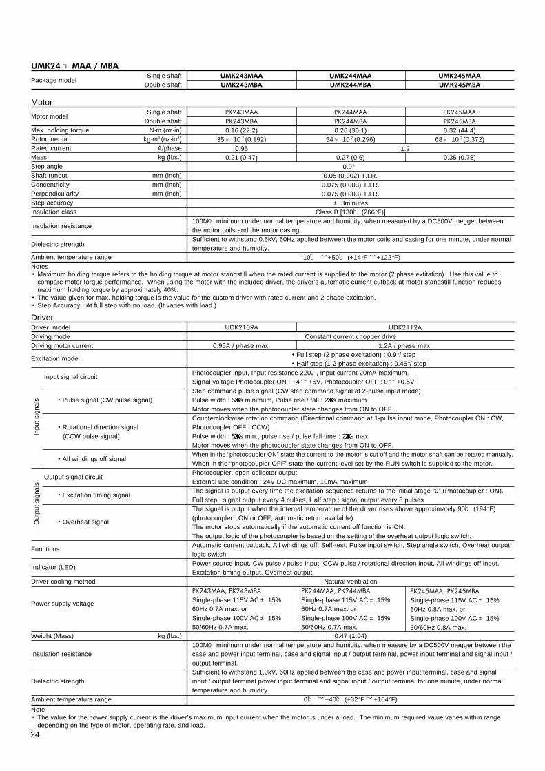
UMK24□MAA / MBA
Package modelSingle shaft
Double shaftUMK245MAAUMK245MBA
UMK244MAAUMK244MBA
UMK243MAAUMK243MBA
MotorMotor model
Single shaftDouble shaft
Max. holding torque N·m (oz·in)Rotor inertia kg·m2 (oz·in2)Rated current A/phaseMass kg (lbs.)Step angleShaft runout mm (inch)Concentricity mm (inch)Perpendicularity mm (inch)Step accuracyInsulation class
Insulation resistance
Dielectric strength
Ambient temperature range
PK245MAAPK245MBA0.32 (44.4)
68× 10-7 (0.372)
0.35 (0.78)
PK244MAAPK244MBA0.26 (36.1)
54× 10-7 (0.296)
0.27 (0.6)
PK243MAAPK243MBA0.16 (22.2)
35× 10-7 (0.192)0.95
0.21 (0.47)0.9°
0.05 (0.002) T.I.R.0.075 (0.003) T.I.R.0.075 (0.003) T.I.R.± 3minutes
Class B [130℃ (266°F)]100MΩ minimum under normal temperature and humidity, when measured by a DC500V megger betweenthe motor coils and the motor casing.Sufficient to withstand 0.5kV, 60Hz applied between the motor coils and casing for one minute, under normaltemperature and humidity.
-10℃ ~ +50℃ (+14°F~ +122°F)
1.2
Notes・Maximum holding torque refers to the holding torque at motor standstill when the rated current is supplied to the motor (2 phase extitation). Use this value to
compare motor torque performance. When using the motor with the included driver, the driver’s automatic current cutback at motor standstill function reducesmaximum holding torque by approximately 40%.
・The value given for max. holding torque is the value for the custom driver with rated current and 2 phase excitation.・Step Accuracy : At full step with no load. (It varies with load.)
PK245MAA, PK245MBASingle-phase 115V AC± 15%60Hz 0.8A max. orSingle-phase 100V AC± 15%50/60Hz 0.8A max.
DriverDriver modelDriving modeDriving motor current
Excitation mode
Input signal circuit
・Pulse signal (CW pulse signal)
・Rotational direction signal (CCW pulse signal)
・All windings off signal
Output signal circuit
・Excitation timing signal
・Overheat signal
Functions
Indicator (LED)
Driver cooling method
Power supply voltage
Weight (Mass) kg (lbs.)
Insulation resistance
Dielectric strength
Ambient temperature range
UDK2112A
1.2A / phase max.
UDK2109A
0.95A / phase max.Constant current chopper drive
・Full step (2 phase excitation) : 0.9°/ step・Half step (1-2 phase excitation) : 0.45°/ step
Photocoupler input, Input resistance 220Ω, Input current 20mA maximum.Signal voltage Photocoupler ON : +4~ +5V, Photocoupler OFF : 0~ +0.5VStep command pulse signal (CW step command signal at 2-pulse input mode)Pulse width : 5μμμμμs minimum, Pulse rise / fall : 2μμμμμs maximumMotor moves when the photocoupler state changes from ON to OFF.Counterclockwise rotation command (Directional command at 1-pulse input mode, Photocoupler ON : CW,Photocoupler OFF : CCW)Pulse width : 5μμμμμs min., pulse rise / pulse fall time : 2μμμμμs max.Motor moves when the photocoupler state changes from ON to OFF.When in the “photocoupler ON” state the current to the motor is cut off and the motor shaft can be rotated manually.When in the “photocoupler OFF” state the current level set by the RUN switch is supplied to the motor.Photocoupler, open-collector outputExternal use condition : 24V DC maximum, 10mA maximumThe signal is output every time the excitation sequence returns to the initial stage “0” (Photocoupler : ON).Full step : signal output every 4 pulses, Half step : signal output every 8 pulsesThe signal is output when the internal temperature of the driver rises above approximately 90℃ (194°F)(photocoupler : ON or OFF, automatic return available).The motor stops automatically if the automatic current off function is ON.The output logic of the photocoupler is based on the setting of the overheat output logic switch.Automatic current cutback, All windings off, Self-test, Pulse input switch, Step angle switch, Overheat outputlogic switch.Power source input, CW pulse / pulse input, CCW pulse / rotational direction input, All windings off input,Excitation timing output, Overheat output
Natural ventilation
0.47 (1.04)100MΩ minimum under normal temperature and humidity, when measure by a DC500V megger between thecase and power input terminal, case and signal input / output terminal, power input terminal and signal input /output terminal.Sufficient to withstand 1.0kV, 60Hz applied between the case and power input terminal, case and signalinput / output terminal power input terminal and signal input / output terminal for one minute, under normaltemperature and humidity.
0℃ ~ +40℃ (+32°F~ +104°F)
PK243MAA, PK243MBASingle-phase 115V AC± 15%60Hz 0.7A max. orSingle-phase 100V AC± 15%50/60Hz 0.7A max.
Out
put s
igna
lsIn
put s
igna
ls
PK244MAA, PK244MBASingle-phase 115V AC± 15%60Hz 0.7A max. orSingle-phase 100V AC± 15%50/60Hz 0.7A max.
Note・The value for the power supply current is the driver’s maximum input current when the motor is under a load. The minimum required value varies within range
depending on the type of motor, operating rate, and load.

25
UMK26□MAA / MBA
Package modelSingle shaft
Double shaftUMK268MAAUMK268MBA
UMK266MAAUMK266MBA
UMK264MAAUMK264MBA
MotorMotor model
Single shaftDouble shaft
Max. holding torque N·m (oz·in)Rotor inertia kg·m2 (oz·in2)Rated current A/phaseMass kg (lbs.)Step angleShaft runout mm (inch)Concentricity mm (inch)Perpendicularity mm (inch)Step accuracyInsulation class
Insulation resistance
Dielectric strength
Ambient temperature range
PK268MAPK268MB1.35 (187)
480× 10-7 (2.63)
1 (2.21)
PK266MAPK266MB0.9 (124)
300× 10-7 (1.64)
0.7 (1.55)
PK264MAPK264MB
0.39 (54.1)120× 10-7 (0.66)
0.45 (1)0.9°
0.05 (0.002) T.I.R.0.075 (0.003) T.I.R.0.075 (0.003) T.I.R.± 3minutes
Class B [130℃ (266°F)]100MΩ minimum under normal temperature and humidity, when measured by a DC500V megger betweenthe motor coils and the motor casing.Sufficient to withstand 1kV, 60Hz applied between the motor coils and casing for one minute, under normaltemperature and humidity.
-10℃ ~ +50℃ (+14°F~ +122°F)
2
Notes・Maximum holding torque refers to the holding torque at motor standstill when the rated current is supplied to the motor (2 phase extitation). Use this value to
compare motor torque performance. When using the motor with the included driver, the driver’s automatic current cutback at motor standstill function reducesmaximum holding torque by approximately 40%.
・The value given for max. holding torque is the value for the custom driver with rated current and 2 phase excitation.・Step Accuracy : At full step with no load. (It varies with load.)
Note・The value for the power supply current is the driver’s maximum input current when the motor is under a load. The minimum required value varies within range
depending on the type of motor, operating rate, and load.
DriverDriver modelDriving modeDriving motor current
Excitation mode
Input signal circuit
・Pulse signal (CW pulse signal)
・Rotational direction signal (CCW pulse signal)
・All windings off signal
Output signal circuit
・Excitation timing signal
・Overheat signal
Functions
Indicator (LED)
Driver cooling method
Power supply voltage
Weight (Mass) kg (lbs.)
Insulation resistance
Dielectric strength
Ambient temperature range
UDK2120AConstant current chopper drive
2A / phase max.・Full step (2 phase excitation) : 0.9°/ step
・Half step (1-2 phase excitation) : 0.45°/ stepPhotocoupler input, Input resistance 220Ω, Input current 20mA maximum.Signal voltage Photocoupler ON : +4~ +5V, Photocoupler OFF : 0~ +0.5VStep command pulse signal (CW step command signal at 2-pulse input mode)Pulse width : 5μμμμμs minimum, Pulse rise / fall : 2μμμμμs maximumMotor moves when the photocoupler state changes from ON to OFF.Counterclockwise rotation command (Directional command at 1-pulse input mode, Photocoupler ON : CW,Photocoupler OFF : CCW)Pulse width : 5μμμμμs min., pulse rise / pulse fall time : 2μμμμμs max.Motor moves when the photocoupler state changes from ON to OFF.When in the “photocoupler ON” state the current to the motor is cut off and the motor shaft can be rotated manually.When in the “photocoupler OFF” state the current level set by the RUN switch is supplied to the motor.Photocoupler, open-collector outputExternal use condition : 24V DC maximum, 10mA maximumThe signal is output every time the excitation sequence returns to the initial stage “0” (Photocoupler : ON).Full step : signal output every 4 pulses, Half step : signal output every 8 pulsesThe signal is output when the internal temperature of the driver rises above approximately 90℃ (194°F)(photocoupler : ON or OFF, automatic return available).The motor stops automatically if the automatic current off function is ON.The output logic of the photocoupler is based on the setting of the overheat output logic switch.Automatic current cutback, All windings off, Self-test, Pulse input switch, Step angle switch, Overheat outputlogic switch.Power source input, CW pulse / pulse input, CCW pulse / rotational direction input, All windings off input,Excitation timing output, Overheat output
Natural ventilationSingle-phase 115V AC± 15% 60Hz 1.3A max. orSingle-phase 100V AC± 15% 50/60Hz 1.3A max.
0.47 (1.04)100MΩ minimum under normal temperature and humidity, when measure by a DC500V megger between thecase and power input terminal, case and signal input / output terminal, power input terminal and signal input /output terminal.Sufficient to withstand 1.0kV, 60Hz applied between the case and power input terminal, case and signalinput / output terminal power input terminal and signal input / output terminal for one minute, under normaltemperature and humidity.
0℃ ~ +40℃ (+32°F~ +104°F)
Out
put s
igna
lsIn
put s
igna
ls

26
Dimensions
Motor Unit : mm (inch)
Note : Shaded areas indicate double shaft models only.
UMK24□ (M)
UMK26□ (M)
Package modelSingle shaftDouble shaft
UMK243AA, UMK243MAAUMK243BA, UMK243MBA
UMK244AA, UMK244MAAUMK244BA, UMK244MBA
UMK245AA, UMK245MAAUMK245BA, UMK245MBA
Motor modelSingle shaftDouble shaft
PK243-01AA, PK243MAAPK243-01BA, PK243MBA
PK244-01AA, PK244MAAPK244-01BA, PK244MBA
PK245-01AA, PK245MAAPK245-01BA, PK245MBA
Dimension Amm (inch)
33± 1 (1.3± 0.04)
39± 1 (1.54± 0.04)
47± 1 (1.85± 0.04)
Dimension Bmm (inch)
48± 2 (1.89± 0.08)
54± 2 (2.13± 0.08)
62± 2 (2.44± 0.08)
Package modelSingle shaftDouble shaft
UMK264AA, UMK264MAA
UMK264BA, UMK264MBAUMK266AA, UMK266MAA
UMK266BA, UMK266MBAUMK268AA, UMK268MAA
UMK268BA, UMK268MBA
Motor modelSingle shaftDouble shaft
PK264-02A, PK264MA
PK264-02B, PK264MBPK266-02A, PK266MA
PK266-02B, PK266MBPK268-02A, PK268MA
PK268-02B, PK268MB
Dimension Amm (inch)
39± 1 (1.54± 0.04)
54± 1 (2.13± 0.04)
76± 1 (2.99± 0.04)
Dimension Bmm (inch)
55± 2 (2.17± 0.08)
70± 2 (2.76± 0.08)
92± 2 (3.62± 0.08)
Note : Shaded areas indicate double shaft models only.
42×42±1(1.65×1.65±.04)
31±0.1(1.22±.004)
31±
0.1(
1.22±
.004
)
20±1(.79±.04)
15±0.25
15±1
(.59±.04)
2(0.08)
NO.4-40UNC
4.5(.17)DEEP MIN.4PLACES
4.5±
0.15
(.17
7±.0
06)
4.5±
0.15
(.17
7±.0
06)
φ5
φ22
0 -0.0
33
0 -0.0
12
.196
8DIA
..1
964D
IA. φ
50 -0
.012
.196
8DIA
..1
964D
IA.
.866
1DIA
..8
648D
IA.
A
B※�
(.59±.04)
6 LEADS 300(11.8) LONG
UL STYLE 3265, AWG 24
47.14±0.35(1.86±.014)
47.1
4±0.
35(1
.86±
.014
)
56.4×
56.4±
1(2.
22×
2.22
)
20±1(.79±.04)
5(.2) 1.6(.06)
15±0.2515±0.25
(.59±.01)
6 LEADS 300(11.8) LONG
UL STYLE 3265, AWG 22
(.59±.01)
5.8±
0.15
(.22
8±.0
06)
5.8±
0.15
(.22
8±.0
06)
16±1(.63±.04)
φ6.
35
φ38
.1±
0.03
φ4.5(.18DIA.)-4HOLES
0 -0.0
12
φ6.
350 -0
.012
.250
0DIA
..2
495D
IA.
.250
0DIA
..2
495D
IA.
1.50
12D
IA.
1.49
88D
IA.
A
B
※ Flat length 15± 0.25 (.59± .01)

27
Driver Unit : mm (inch)
Model : UDK2109A / 2112A / 2120A
80±0.3(3.15±.012)
15±0.2(.59±.008) 45(1.77)
18(.71)max. 2(.08)max.
12-M3 P0.5
M3-17 PLACES
TERMINALSTAND COVER
SLITS
10(.39)
100(3.94) 35(1.38)
10(.
39)
15(.
59)
135(
5.31
)
PIT
CH
7.6
2(.3
)
6.32
(.25
)
6.9(
.27)
14(.
55)
Mounting bracket Unit : mm (inch)
Mounting bracket A Mounting bracket B
2(.08)
15(.
59)
15(.59)
35(1.38)
10(.
39)
7.5(
.3)
4.5(.18)
15±0.3(.59±.012)
φ3.5(.138DIA.) COUNTERSINK 2 PLACE
20±0.3(.79±.012)35(1.38)
28(1
.1)
2(.08)
7.5(
.3)
5(.2
)
4.5(.18)
20±0.3(.79±.012)
15±0.3(.59±.012)
φ3.5(.138DIA.) COUNTERSINK 2 PLACE

28
ORIENTAL MOTOR U.S.A. CORP.Technical Support Line Tel:(800)468-3982Available from 7:30 AM to 5:00 PM, P.S.T.E-mail: [email protected]
ORIENTAL MOTOR CO., LTD.Headquarters Tokyo, JapanTel:(03)3835-0684 Fax:(03)3835-1890
• Characteristics, specifications and dimensions are subject to change without notice.• Please contact your nearest ORIENTAL MOTOR office for further information.
Printed on Recycled Paper