operating manual scl-055 - orbit motion systems to the ec machine guidelines 2006/42/ec eln...
TRANSCRIPT

Legal notice© All rights reserved ELAU AG, even in the case of application for property rights. No part of this documentation or the accompanying software and firmware may bereproduced, transferred, paraphrased, saved to a storage medium or translated toanother language or computer language without the written consent of ELAU AG. All possible measures were taken to ensure the completeness and correctness of thisproduct documentation. However, as improvements are continually being made to thehardware and software, ELAU AG cannot guarantee its completeness or correctness.
TrademarkPacDrive is a registered trademark of ELAU AG. All other trademarks named in this documentation are the sole property of their re‐spective manufacturer.
ELAU AGDillberg 1297821 Marktheidenfeld, GermanyTel.: +49 (0) 9391 / 606 - 0Fax: +49 (0) 9391 / 606 - 340E-mail: [email protected]: www.elau.de
Legal notice
Page 2 PacDrive ELAU AG
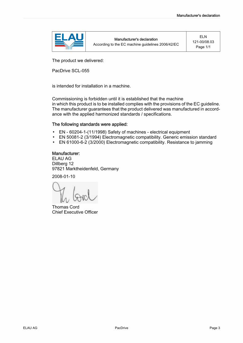
Manufacturer's declarationAccording to the EC machine guidelines 2006/42/EC
ELN121-00/08.03
Page 1/1
The product we delivered:
PacDrive SCL-055
is intended for installation in a machine.
Commissioning is forbidden until it is established that the machinein which this product is to be installed complies with the provisions of the EC guideline.The manufacturer guarantees that the product delivered was manufactured in accord‐ance with the applied harmonized standards / specifications.
The following standards were applied:
▪ EN - 60204-1-(11/1998) Safety of machines - electrical equipment▪ EN 50081-2 (3/1994) Electromagnetic compatibility. Generic emission standard▪ EN 61000-6-2 (3/2000) Electromagnetic compatibility. Resistance to jamming
Manufacturer:ELAU AGDillberg 1297821 Marktheidenfeld, Germany2008-01-10
Thomas CordChief Executive Officer
Manufacturer's declaration
ELAU AG PacDrive Page 3

Table of Contents
1 About this manual 61.1 Introduction ............................................................................................................... 61.2 Symbols, Designator and display format of safety notes ......................................... 7
2 General safety instructions 82.1 Principle .................................................................................................................... 82.2 Selection and qualification of personnel ................................................................... 82.3 Proper use ................................................................................................................ 92.4 Residual Risks ........................................................................................................ 10
3 Overview 133.1 PacDrive System .................................................................................................... 13
4 Indicators, control elements and diagnosis 154.1 Indicators and control elements ............................................................................. 154.2 Example of a diagnostic message .......................................................................... 17
5 Transport, storage, unpacking 185.1 Transport ................................................................................................................ 185.2 Storage ................................................................................................................... 185.3 Unpacking .............................................................................................................. 185.4 Type plate ............................................................................................................... 18
6 Installation and maintenance 206.1 First Installation ...................................................................................................... 206.1.1 The PacDrive SCL-055 with the "positive pressure" option .................................... 226.1.2 Nodes in the SERCOS-Ring .................................................................................. 236.2 Configuration and Calibration ................................................................................. 246.3 EMC Rules ............................................................................................................. 256.4 Maintenance, Repair, Cleaning .............................................................................. 266.5 Spare Parts ............................................................................................................ 27
Table of Contents
Page 4 PacDrive ELAU AG

6.6 Order numbers ....................................................................................................... 286.7 Device replacement ................................................................................................ 306.8 Cable replacement ................................................................................................. 31
7 Technical data 367.1 General ................................................................................................................... 367.1.1 Definitions ............................................................................................................... 377.1.2 Installation and Protection class ............................................................................. 387.1.3 Motor shaft and bearings ........................................................................................ 397.1.4 Encoder .................................................................................................................. 407.1.5 Torque/speed characteristic curves ....................................................................... 407.2 Electrical Connections ............................................................................................ 427.3 Dimensions ............................................................................................................. 44
8 Appendix 468.1 Contact addresses ................................................................................................. 468.2 Product Training Courses ....................................................................................... 468.3 Changes ................................................................................................................. 478.4 Fault report form ..................................................................................................... 48
Table of Contents
ELAU AG PacDrive Page 5

1 About this manual
1.1 Introduction
Read this manual before you use the motor for the first time. Take particular note ofthe safety instructions. As described in section 2.4, only those persons who meet theselection and qualification of employees are allowed to work on this unit.
A copy of this manual must always be available for personnel who are entrusted towork on the motors.This manual is designed to help you use the motor and its intended applications safelyand properly. Follow the instructions in this manual. Doing so helps avoid hazards, minimize repaircosts and downtime, extend service life and increase reliability.You must also observe the rules and regulations on accident prevention and environ‐mental protection that apply in the country where the product is used and at theinstallation location.
1 About this manual
Page 6 PacDrive ELAU AG

1.2 Symbols, Designator and display format of safety notes
The safety notes in this manual are divided into various categories. The following tableshows the hazard and possible consequences indicated by the symbol (pictogram)and the signal words.
Representation MeaningGeneral safety symbols: Safety instructions are presented at the relevantpoints. They are marked with this symbol.
Indicates an immediate hazardous situation that can lead to death orserious bodily injury if the safety regulations are not observed.Indicates a potentially dangerous situation that may result in seriousbodily harm or property damage if the safety instructions are not followed.Indicates a potentially dangerous situation that may result in minor bodilyharm or property damage if the safety instructions are not followed.
The following symbols and designators are used in this document:
Representation MeaningInformation symbol: After this symbol, you will find instructions and usefultips on using the components.Information serving as an orientation aid regarding the section's contentsfollows this symbol.
Keyword If the descriptive text contains technical terms (such as parameters), theyare highlighted in bold.Program code is written in a different font.
First level bullet pointSecond level bullet point.
Activity symbol: The text after this symbol contains instructions. Followthem in sequence from top to bottom.Result symbol: The text after this symbol contains the result of an action.
1.2 Symbols, Designator and display format of safety notes
ELAU AG PacDrive Page 7

2 General safety instructionsThis section contains general requirements for safe work. Each person who uses orworks on motors must read and follow these general safety notes.If activities involve residual risks, a specific note is made at the appropriate points. Thenote details the potential danger and describes preventative measures to avoid it.
2.1 Principle
The motors are state of the art and conform to recognized technical safety regulations.Nevertheless the use can present a hazard to life and limb or cause material damage,if:
▪ You do not use them as intended.▪ Work on them is not performed by specialists or other trained personnel.▪ You change or modify them inappropriately.▪ You neglect to test the protective measures in use after the installation, commis‐
sioning or repair.▪ You do not observe the safety notes and safety regulations.
The installation requires you to provide for appropriate safety devices in compliancewith the local and national standards. Commissioning without appropriate safety de‐vices is expressly forbidden.Operate the motors only when they are in a flawless technical condition. Observe theregulations, act with safety and hazards in mind, and follow the instructions in thismanual. In order for the motors to run perfectly and safely, they must be transported,stored, installed, and assembled correctly and serviced carefully.If circumstances occur that impact safety or cause changes in the operating perform‐ance of motors, switch it off immediately and contact the responsible service staff.As a supplement to this description, please observe:
▪ The regulative, warning, and instruction signs as well as the warning instructionson the motors, the connected components, and all signs in the switching cabinet.
▪ The operating instructions of the other components.▪ The generally applicable local and national safety and accident prevention regu‐
lations.▪ The applicable laws and ordinances.
2.2 Selection and qualification of personnel
This description is geared exclusively toward technically qualified personnel, who havedetailed knowledge in the field of automation technology. Only qualified personnel canrecognize the importance of the safety instructions and implement them consistently.The description is mainly for construction and application engineers from the engi‐neering and electro-technics division as well as service and commissioning engineers.
2 General safety instructions
Page 8 PacDrive ELAU AG

Professional or training personnelWork on the motor may only be carried out by qualified professional or by trained staffunder the instruction and supervision of a qualified person in accordance with electricalregulations.Qualified persons are only those persons who can perform the following tasks as aresult of their training, knowledge, and experience:
▪ evaluate the transferred work,▪ recognize possible hazards and▪ take appropriate safety measures.
2.3 Proper use
The motor is intended to be installed in a machine or assembled with other componentsto form a machine or system. You may only use them in accordance with the installationand operating conditions described in the documentation. Use only the accessoriesand add-ons specified in the documentation. You may not use any third-party devicesor components that are not expressly approved by ELAU.The ELAU components must not be used in the following environments:
▪ In dangerous (explosive) atmospheres▪ In mobile, movable or floating systems▪ In life support systems▪ In domestic appliances
The motor is part of the PacDrive System. The PacDrive System is the complete con‐trol system comprising of
▪ PacDrive Controller of C- or P-Series,▪ PacDrive Servo amplifier MC-4 and▪ PacDrive Motor
For proper use, you must also:
▪ Observe the operating instructions and other documents (see Appendix).▪ Comply with the inspection and servicing instructions.
The operating conditions at the installation location must be checked and maintainedin accordance with the required technical specifications (performance data and ambi‐ent conditions). Start-up is prohibited until it is guaranteed that the usable machine orsystem in which the motor is installed meets all requirements of the EC Directive 98/37/EC (machinery directive).In addition, the following standards, directives and regulations are to be observed:
▪ DIN EN 60204 Safety of machinery: Electrical equipment of machines▪ DIN EN 292 Part 1 and Part 2 Safety of machinery: Basic Concepts, General Prin‐
ciples for Design▪ DIN EN 50178 Electronic equipment for use in power installations▪ EMC directive 89/336/EEC : DINT
2.3 Proper use
ELAU AG PacDrive Page 9

2.4 Residual Risks
Health risks arising from the motor have been reduced by means of safety technologyand design engineering.However a residual risk remains, since the motor works with electrical voltage andelectrical currents.Mounting and handling
WARNINGRisk of injury during handling!Risk of bodily harm from crushing, shearing, cutting, and hitting!▪ Observe the general construction and safety regulations for handling and instal‐
lation.▪ Use suitable installation and transport equipment correctly and use special tools
if necessary.▪ Prevent clamping and crushing by taking appropriate precautions.▪ Wear suitable protective clothing (for example, safety goggles, safety boots, pro‐
tective gloves).▪ Do not stand under suspended loads.
Touching electrical partsIf parts have contact with voltages greater than 50 V, it can be a threat for personnel.When electrical devices are in operation, certain parts of these devices can necessarilycarry dangerous voltages.
DANGERHigh voltage!Risk of death!▪ Observe the general construction and safety regulations for working on high-cur‐
rent electrical systems.▪ After installation, check the fixed connection of the ground conductor to all elec‐
trical units to ensure that connection complies with the connection diagram.▪ Generally, and also for brief measurements and inspections, operation is only
allowed using a fixed connection from the ground conductor to all electrical com‐ponents.
▪ Disconnect the unit from the power supply before working on electrical parts witha voltage greater than 50 volts. Prevent the unit from being switched back on. Waitat least 5 minutes after shutting down before accessing the components. Checkthe voltage with a voltage meter before accessing the unit to be sure that thevoltage is less than 50 volts.
▪ Do not touch the electrical connection points of the components when the unit isswitched on.
▪ Before switching on the unit, safely cover the live components to prevent contact.▪ The following provides protection against indirect contact (DIN EN 50178, Section
5.3.2).
2 General safety instructions
Page 10 PacDrive ELAU AG

High Leakage Current
DANGERHigh leakage current!Risk of death!▪ The leakage current is greater than 3.5 mA. This is why units require a fixed con‐
nection to the power supply network (in accordance to DIN EN 50178 - Equippinghigh-current electrical systems).
Touching hot surfaces
The housing temperature of the motor exceeds 70°C during nominal operation. Aswarning, the symbol shown here is affixed on the motor.
Dangerous MovementsThere are several causes for hazardous activities:
▪ Wiring or cabling errors▪ Software errors▪ Module error in the components▪ Error in the measured value and signal transmitter▪ Operation error
Protection of personnel must be ensured via higher-level, line-side monitoring. Do notonly rely on the internal monitoring of the drives components. Monitoring or other ar‐rangements depend on the specific conditions of the installation and have to be doneby the system manufacturer, according to the danger and error analysis. The safetyregulations for the installation are included. Under no circumstances must the technicalsafety devices be removed. Do not make any modifications to a safety device that mayput it out of operation. Protect existing work stations against unauthorized operation.Effectively restrict access to the control terminals to allow access only to authorizedpersons.
DANGERDangerous Movements!Risk of death, serious injury or property damage!▪ Prevent entry to a danger zone, for example with protective fencing, mesh guards,
protective coverings, or light barriers.▪ Ensure the protective devices are properly dimensioned.▪ The EMERGENCY OFF switch must be located very close to the operator. The
functionality of EMERGENCY OFF equipment should be checked before start-upand during maintenance periods.
▪ Prevent unintentional start-ups by disconnecting the power connection of the driveusing the EMERGENCY OFF circuit or using a secure start-up lock out.
▪ Before accessing or entering the danger zone, safely bring the drives to a stop.▪ While working on the system, de-energize the electrical equipment using the main
switch and prevent it from being switched back on.▪ Avoid operating high-frequency, remote control, and radio devices close to the
unit and system electronics and their feed lines. If the use of such devices cannotbe avoided, the system and the installation must be checked for possible mal‐functions in all usage scenarios prior to the initial start-up. Where applicable, it isnecessary to carry out a special EMC check of the system.
2.4 Residual Risks
ELAU AG PacDrive Page 11

"Safe separated extra-low voltage"PELV Protec‐
tive Extra-LowVoltage
The signal voltage and control voltage of the PacDriveTM devices are <33 Volts. In thisrange and in accordance with IEC 60364-4-41, the specification as PELV system con‐tains a protective measure to guard against direct and indirect contact with dangerousvoltage through "safe separation" of the primary and secondary side in the system/machine. ELAU strongly recommends providing the system/machine with safe isola‐tion.
DANGERHigh voltage due to incorrect connection!Risk of death or serious injury!▪ Please ensure that only devices, electrical components or lines that have a suffi‐
cient, safe electrical separation from the connected circuits in accordance with thestandards (EN 50178 / 1998 edition - Electronic equipment for use in power sta‐tions) are connected to the signal voltage connectors of this component.
▪ Ensure that the existing electrical separation is maintained throughout the entirecircuit.
FELV Function‐al Extra-Low
Voltage
When using ELAU components in systems that do not have safe separation as a pro‐tective measure against direct or indirect contact of dangerous voltages, all connec‐tions and contacts (e.g. PacDrive controller, Sub-D connector, serial interface) that donot meet the protection class IP2X require a permanent cover. The cover or the deviceconnection of the connected device must be designed so that it can only be removedby using a tool. The protective measures have to be adhered on all connected devices.Protection against magnetic and electromagnetic fieldsMagnetic and electromagnetic fields that are in immediate environments of electricalconductors and permanent motor magnets represent a serious health hazard to per‐sons with heart pacemakers, metal implants and hearing aids.
WARNINGHealth risk posed by risk groups in the proximity of electrical equipment.Do not allow personnel with pacemakers or similar sensitive implants to work on mo‐tors!
2 General safety instructions
Page 12 PacDrive ELAU AG

3 Overview
3.1 PacDrive System
Figure 3-1: PacDrive System Overview
PacDrive controller family
The PacDrive controller, microprocessor-based control hardware with the VxWorksreal-time operating system, centrally implements the PLC and motion functions. A PacDrive controller synchronizes, coordinates, and creates the motion functions formaximum
▪ 8 drives for the PacDrive controller C200▪ 2 drives for the PacDrive controller C200 A2▪ 16 drives for the PacDrive controller C400▪ 8 drives for the PacDrive controller C400 A8▪ 99 drives for the PacDrive controller MAx-4 / 99▪ 99 drives for the PacDrive controller C600of a food and packaging machine. Different standard HMIs are used for the HMI tasks. Whether it is low cost, plain textor IPC, it is no problem for the flexible PacDrive controllers. The PacDrive P600 controller is additionally equipped with a full-fledged PC. Due toits PC-based architecture, it can perform HMI tasks with no problem in addition to theusual motion functions.
3.1 PacDrive System
ELAU AG PacDrive Page 13

PacDrive PS-4
The power supply unit PS-4 is characterized by a compact and autonomous structurefor swapping housing installations with highly modern technology. All PacDrive SCLsare supplied power only through one connection via PacDrive PS-4, which can beinstalled quickly.The highlights:
▪ 1 or 3 phase power supply▪ Integrated network filter and bleeder▪ 5 kW rated current / 10 kW peak current▪ Direct current for up to 32 SCL-055▪ Comprehensive diagnosis possibilities
PacDrive PD-8
The PacDrive PD-8 represents the combination of PS-4 and SCL-055. A distributor tothe 1 to 8 SCL-055 can be connected. If more than 8 drives are to be operated, it canbe easily expanded with one or more PD-8 distributors.The highlights:
▪ 1 to 8 connections to the SCL-055▪ Easily expandable▪ Aseptic variants available
PacDrive SCL
The innovative SCL combines motor, final stages and the digital servo regulator forone axis in a space-saving housing. Its compact size combines motor and power elec‐tronics in the smallest space. It is excellent for decentral installations. The SCL isavailable with single or multi-turn encoders and configures itself with the help of theelectronic type plate in the SCL itself.
The highlights:
▪ Integrated SERCOS interface▪ High-resolution single or multi-turn encoder▪ IP 65 / IP 67 protection class▪ Superior reliability▪ Trapezoid shape▪ Aseptic variants IP67 (with positive pressure)▪ Stainless steel housing
3 Overview
Page 14 PacDrive ELAU AG

4 Indicators, control elements and diagnosisThe PacDrive™ system supports the user with its comprehensive diagnostic sys‐tem. The diagnostic messages can be read out with the Automation Toolkit EPAS-4. APacDrive controller can be the field bus master or the slave. Diagnostic messages are usually displayed by a control panel on the machine. If an "error" occurs, read the message on this unit and then contact the machine man‐ufacturer.
NOTEYou can find detailed diagnosis information in the Online Help of the AutomationToolkit EPAS-4.
4.1 Indicators and control elements
The PacDrive SCL is equipped with diagnostic LEDs for on-location diagnostics.After removing the SERCOS address switch dust cap,an initial diagnosis is possible directly on the PacDrive SCL with the help of the LED's.Green diagnostic LED
������������ ����� �������� � �������������������� �
������������������������ � ��������������� ������ ��� �����������
������������ ������������� � ��������� ������ ������� ������!�������� ��� �����"�������������#
�
��
�
��
�
��
$ $%&' $%() )%$& ��������
��������
��������
&%$(
!�*���� ��*���*�����*��%��+
������ ,������� ��� �������������������,������� ����� �
��
��������)%$& &%$(
Figure 4-1: Status indicator of green diagnosis LED on SCL
4.1 Indicators and control elements
ELAU AG PacDrive Page 15

Red diagnostic LED������������ ����� ���� �
������������������������ �
������ ,����������������� �� �� ��� �������� �����
������ ���������� ���� �������� �������������� ������� �����������������
������������ ���������������� �
�
��
�
��
�
��
�
��
�
��
$ $%&' $%() )%$& ��������
��������
��������
��������
��������
$ )%$& &%$(
$ $%&' &%$(
&%$(
!�*���� ��*���*� �*��%��+
Figure 4-2: Status indicator of red diagnosis LED on SCL
SERCOS-Address Rotary SwitchWith the S1 and S2 rotary switches you can set the SERCOS address (0 - 99) of thedevice; on Switch S1 the tens digits and on Switch S2 the units digits.
4 Indicators, control elements and diagnosis
Page 16 PacDrive ELAU AG

0 2 3 456
1
789
0 2 3 456
1
789
tens digit
SERCOS adress:
units digit
optionalsensor/actuator connectionof the SCL standard
Figure 4-3: Rotary switch to set the SERCOS address
4.2 Example of a diagnostic message
The diagnostic message 121 "braking resistor temperature too high" is displayed.Meaning of this:
▪ Class 2 error▪ Diagnostic code 121
The meaning of the diagnostic code is more thoroughly explained in the online helpsection of the EPAS-4 automation toolkit.121 braking resistor temperature too highDiagnosis class (standard): 2Reaction: BThe braking resistor is overloaded.
▪ The drive has incorrect dimensions.▶ Check drive sizing.
▪ Hardware error: The braking resistor or addressing is defective.▶ Contact ELAU customer service.
4.2 Example of a diagnostic message
ELAU AG PacDrive Page 17

5 Transport, storage, unpacking
5.1 Transport
▪ Avoid heavy shocks and/or vibrations during transport.▪ Check the units for visible transport damage and inform the shipping company
immediately if necessary.
5.2 Storage
▪ Store devices in a clean, dry room.▪ The air temperature at the storage location must be between - 25 °C and + 70 °C.▪ Possible temperature variations at the storage location must be maximum 30 K per
hour.
5.3 Unpacking
▪ Remove packaging.▪ Check delivery for completeness.▪ Check all units for transport damage.
5.4 Type plate
The type plate contains all important information:
Figure 5-1: Type plate of the PacDrive SCL 15010
5 Transport, storage, unpacking
Page 18 PacDrive ELAU AG
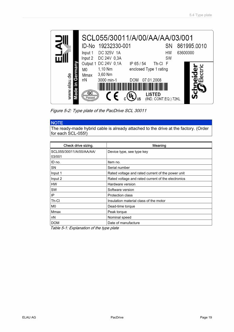
Figure 5-2: Type plate of the PacDrive SCL 30011
NOTEThe ready-made hybrid cable is already attached to the drive at the factory. (Orderfor each SCL-055!)
Check drive sizing. MeaningSCL055/30011/A/00/AA/AA/03/001
Device type, see type key
ID no. Item no.SN Serial numberInput 1 Rated voltage and rated current of the power unitInput 2 Rated voltage and rated current of the electronicsHW Hardware versionSW Software versionIP Protection classTh-Cl Insulation material class of the motorM0 Dead-time torqueMmax Peak torquenN Nominal speedDOM Date of manufactureTable 5-1: Explanation of the type plate
5.4 Type plate
ELAU AG PacDrive Page 19

6 Installation and maintenanceWe strongly recommend that you contact ELAU personnel for the initial start-up. Thisis not only for guarantee reasons, but also that:
▪ The equipment will be checked,▪ The optimal configuration recorded and▪ Operating staff can be instructed.
6.1 First Installation
This is how you proceed with the commissioning:Testing ▶ Check device for sound condition.
Only operate undamaged devices.▶ Check data against type plates.
Refer also to chapter Packaging and Device Replacement.
High Leakage Current
DANGERHigh leakage current!Risk of death!▪ The leakage current is greater than 3.5 mA. This is why units require a fixed con‐
nection to the power supply network (in accordance to DIN EN 50178 - Equippinghigh-current electrical systems).
SERCOSaddress
▶ Remove the protective cap from the SERCOS address switch on the SCL.
▶ Using an appropriate tool, on the back of the motor, set the specified SERCOSaddress (0-99) of the node according to the machine diagram.
NOTEBe extremely careful not to assign an address more than once in a SERCOS ring.Each drive must have its own unique SERCOS address.
▶ Tighten dust cap and check that it is tight.
You receive the PacDrive SCL with prepackaged cable already attached on the motorside. Connect the cable to the PacDrive PD-8 as follows:
Installation ▶ Observe requirements for the installation location.▶ Observe requirements for the protection class and the EMC rules.
▶ Install device.
6 Installation and maintenance
Page 20 PacDrive ELAU AG

SCL Connec‐tion
to electricity
!�-+*.����%��+
�������� ������ �� ������ �� ������ �� ������ �� ����������
������� ������ �� ������ �� ������ �� ������ �� ���������
Figure 6-1: PD-8 cable glands
▶ Remove dust cap of cable gland on the PD-8.▶ Push the cable of the first/next SCL-055 through the SCL-055 (1-8) opening.
(For SCL-055 (1) connection, begin in ascending order up to SCL-055 (8).Ob‐serve sequence!)
(3)(1) (2)
(4) (6)(8)
(5)
(7)
Figure 6-2: Connection of the SCL-055 to the PacDrive PD-8
(1) Power supply(2) Jumper for scheduling(3) SERCOS connector (SCL)(4) SERCOS cable(5) Cap nut(6) Cable gland(7) Fuse
6.1 First Installation
ELAU AG PacDrive Page 21
(8) Dummy plug
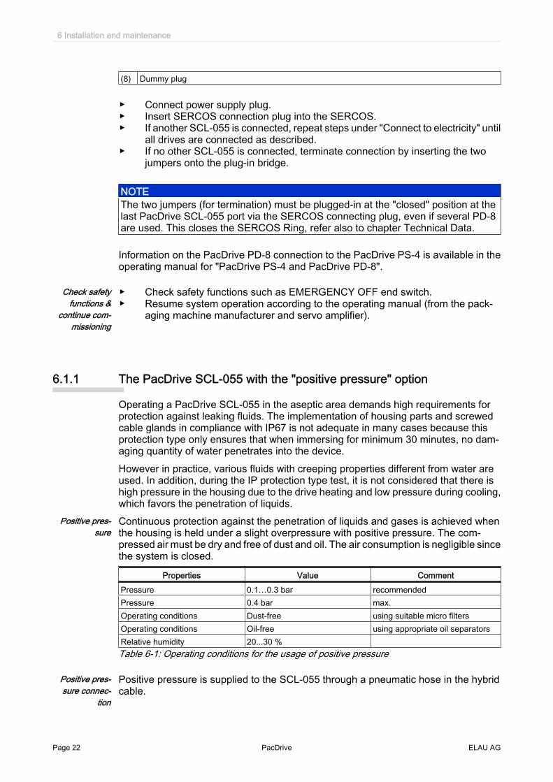
▶ Connect power supply plug.▶ Insert SERCOS connection plug into the SERCOS.▶ If another SCL-055 is connected, repeat steps under "Connect to electricity" until
all drives are connected as described.▶ If no other SCL-055 is connected, terminate connection by inserting the two
jumpers onto the plug-in bridge.
NOTEThe two jumpers (for termination) must be plugged-in at the "closed" position at thelast PacDrive SCL-055 port via the SERCOS connecting plug, even if several PD-8are used. This closes the SERCOS Ring, refer also to chapter Technical Data.
Information on the PacDrive PD-8 connection to the PacDrive PS-4 is available in theoperating manual for "PacDrive PS-4 and PacDrive PD-8".
Check safetyfunctions &
continue com‐missioning
▶ Check safety functions such as EMERGENCY OFF end switch.▶ Resume system operation according to the operating manual (from the pack‐
aging machine manufacturer and servo amplifier).
6.1.1 The PacDrive SCL-055 with the "positive pressure" option
Operating a PacDrive SCL-055 in the aseptic area demands high requirements forprotection against leaking fluids. The implementation of housing parts and screwedcable glands in compliance with IP67 is not adequate in many cases because thisprotection type only ensures that when immersing for minimum 30 minutes, no dam‐aging quantity of water penetrates into the device.However in practice, various fluids with creeping properties different from water areused. In addition, during the IP protection type test, it is not considered that there ishigh pressure in the housing due to the drive heating and low pressure during cooling,which favors the penetration of liquids.
Positive pres‐sure
Continuous protection against the penetration of liquids and gases is achieved whenthe housing is held under a slight overpressure with positive pressure. The com‐pressed air must be dry and free of dust and oil. The air consumption is negligible sincethe system is closed.
Properties Value CommentPressure 0.1…0.3 bar recommendedPressure 0.4 bar max.Operating conditions Dust-free using suitable micro filtersOperating conditions Oil-free using appropriate oil separatorsRelative humidity 20...30 %Table 6-1: Operating conditions for the usage of positive pressure
Positive pres‐sure connec‐
tion
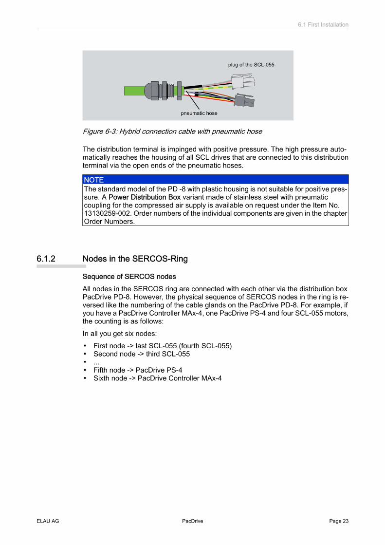
Positive pressure is supplied to the SCL-055 through a pneumatic hose in the hybridcable.
6 Installation and maintenance
Page 22 PacDrive ELAU AG
plug of the SCL-055
pneumatic hose
Figure 6-3: Hybrid connection cable with pneumatic hose
The distribution terminal is impinged with positive pressure. The high pressure auto‐matically reaches the housing of all SCL drives that are connected to this distributionterminal via the open ends of the pneumatic hoses.
NOTEThe standard model of the PD -8 with plastic housing is not suitable for positive pres‐sure. A Power Distribution Box variant made of stainless steel with pneumaticcoupling for the compressed air supply is available on request under the Item No.13130259-002. Order numbers of the individual components are given in the chapterOrder Numbers.
6.1.2 Nodes in the SERCOS-Ring
Sequence of SERCOS nodesAll nodes in the SERCOS ring are connected with each other via the distribution boxPacDrive PD-8. However, the physical sequence of SERCOS nodes in the ring is re‐versed like the numbering of the cable glands on the PacDrive PD-8. For example, ifyou have a PacDrive Controller MAx-4, one PacDrive PS-4 and four SCL-055 motors,the counting is as follows:In all you get six nodes:
▪ First node -> last SCL-055 (fourth SCL-055)▪ Second node -> third SCL-055▪ ...▪ Fifth node -> PacDrive PS-4▪ Sixth node -> PacDrive Controller MAx-4
6.1 First Installation
ELAU AG PacDrive Page 23

MAx-4
SCL 1 SCL 2 SCL n
*) for information about external power via slip ring see Operation Manual PacDrive PS-4 / PD-8
upgradeablewith e.g. MC-4
LWL
Cu
PS-4
SCL055SERCOS
fiber optic cable transmissioncopper-transmission
SCL055
slip
ring
*)
SERCOS
SCL055SERCOSSERCOS
Figure 6-4: Signal transmission and numbering of SERCOS nodes
Change the number of nodes in the SERCOS ringIf the number of SERCOS nodes changes, you must carry out the termination as de‐scribed for the PacDrive SCL-055 according to the chapter Commissioning.
NOTEDuring commissioning, if certain circumstances result in a temporary change in thenumber of nodes, you need not remove all the cabled PacDrive SCL-055 again. Pro‐ceed as in the example below.
Example 24 SCL-055 motors are running on your system (already fully cabled). For test pur‐poses, you want to reduce the number of slaves to 10 motors.Proceed as follows:
▶ Remove the plug of the 11th SERCOS connection (this corresponds to the con‐nection (3) of the second PacDrive PD-8 Box). This ensures that the physicalconnection to the subsequent SERCOS node is broken. Connect the powersupply plug.
▶ Terminate the 10th SCL-055 motor by inserting the jumper.▶ Remove the plug of the SERCOS connection from the SERCOS port that leads
to the subsequent PacDrive PD-8 box.▶ With that you have reduced the SERCOS ring to 10 motors.
NOTEIt is not enough to place the jumpers at the desired terminations; even no slave shouldbe inserted on the next SERCOS plug-in slot!
6.2 Configuration and Calibration
The PacDrive™ system is adapted to your task using the EPAS-4 automation tool‐kit.The system will be configured and programmed according to IEC 61131-3 in EPAS-4.
6 Installation and maintenance
Page 24 PacDrive ELAU AG

CAUTIONComplex functionality of the PacDrive™ system and the machine!Property damage possible!▪ Program changes may only be carried out by trained personnel with detailed
knowledge of the system. In other words, changes may only be carried out by yourmachine supplier or by ELAU employees. ELAU AG is not liable for damagescaused by unauthorized program changes.
6.3 EMC Rules
To control and regulate the motors, the mains voltage is stored by rectification in theDC link of the servo amplifier. This stored energy is supplied to the motor by a targetedswitching on and off using six semiconductor switches. The steep increase/decreasein voltage places considerable demands on the dielectric strength of the motor winding.An important additional aspect to observe is the electromagnetic compatibility (EMC)with other system components. The high rate of change of the clocked voltage gen‐erates harmonics of great intensity up into the high frequency range.
6.3 EMC Rules
ELAU AG PacDrive Page 25

CAUTIONElectromagnetic fields!A interference or breakdown of the system possible!▪ Observe the following rules during installation to eliminate excessive interference
effects and their consequences as much as possible.▪ During installation, select the earthing option with the lowest resistance for high
frequency operation (e.g. unpainted sub plate in switch cabinet).▪ Ensure largest contact surface area possible (skin effect). This ensures that the
physical connection to the subsequent SERCOS nodes is broken.▪ Lay the grounding in a star configuration from the central earthing point to the
corresponding connections. Current loops of earthing are prohibited and cancause unnecessary interference.
▪ Use shielded cable only.▪ Ensure large shielding transitions. (Connecting shielding via PIN contacts of plug-
in connectors is not permitted.)▪ It is necessary to observe the circuit suggestions.▪ Shorten motor cable to minimum length.▪ Do not lay any cable loops in the switching cabinet.▪ In conjunction with electronic controllers, no inductive loads may be switched
without suitable fault clearance.▪ Appropriate interference suppression is achieved during direct current operation
by using recovery diodes and by using protector type-based, industry-standardquenching circuits during alternating current activity.
▪ Only a fault clearance element placed directly at the inductivity serves the pur‐pose. In some cases even more interference may be generated by the shock ofthe switching current on the interference suppression lines. It is far easier to avoidthe source of interference than to eliminate the effects of existing interference.
▪ Contacts that do not switch suppressed inductive loads should never be arrangedin a room with ELAU PacDrive components.The same applies for connection linesthat do not lead suppressed, switched inductances and lines that run parallel tothem. The controller must be separated from such "interferers" using a Faradaycage (own switch cabinet section).
▪ Mains filters and motor filters may by used depending on the combination of theservo amplifier/motor and the cable length. Delete files on the flash disk using anFTP client.Mains filters and motor filters may by used depending on the combination of theservo amplifier/motor and the cable length. Delete files on the flash disk using anFTP client.
6.4 Maintenance, Repair, Cleaning
Quick detection and correction of faults during machine downtime help keep produc‐tion downtime to a minimum.The diagnosis messages of the PacDrive system, which can be queried using theAutomation Toolkit EPAS, allow specific and effective fault location.In the event of a breakdown it is possible to smoothly replace defective componentsto guarantee that the fault is quickly eliminated and operation can be resumed. Thesejobs may only be carried out by qualified maintenance personnel.When returning a defective unit to the ELAU customer services, we request that youfill out the fault report in the appendix.
6 Installation and maintenance
Page 26 PacDrive ELAU AG

NOTETo avoid damage in transport and to guarantee that the repair process goes smoothly,follow the method outlined in the chapter on "Device Replacement".
CleaningThe standard cooling method of the motor is by natural convection. Therefore, keepthe motor surfaces free from dirt build-up.
CAUTIONImproper cleaningProperty damage possible!▪ Program changes may only be carried out by trained personnel with in-depth
knowledge of the system.▪ Use cleaning processes appropriate to the protection class of the motor.
6.5 Spare Parts
Spares inventoryKeeping a stock of the most important components is an important prerequisite forequipment to function constantly and be ready for operation at all times.
NOTENote device compatibility.Devices may only be replaced by devices with the same hardware configuration andsoftware version.
Indicate the following information on the spare part order:Item name: e. g. PacDrive SCL-055:Item no.: e.g. SCL055/30011/A/00/AA/AA/03/001Hardware code: not specifiedSoftware version: not specified
You will find this information on the type plate and in the controller configuration of thePacDrive System.
6.5 Spare Parts
ELAU AG PacDrive Page 27

6.6 Order numbers
Servo Drive SCL - Type code
SCL055 / 30 011 / A / 00 / AA / AA / 03 / 001
Flange size
Speed nN15, 30 (x 100 min-1)
Torque M0010 (/10 Nm) = stainless steel 011 (/10 Nm) = standard
ElectronicsA = with attached motor electronic
Shaft version0 = Standard shaft without feather key1 = Standard shaft with feather key acording to DIN 68852 = Stainless stell shaft without feather key3 = Stainless stell shaft with feather key according to DIN 6885
Casing type0 = Self-cooling
Connection technology / motorA = hybrid connector on the motorB = patch connector
Connection technology / IO0 = no I/OA = M12-plug
Protection class shaftA = without shaft sealing ring, without labyrinth seal / IP54B = with shaft sealing ring, with labyrinth seal / IP65
Protection class casingA = IP65B = IP67 (nur für Aseptic)
Encoder feedback03 = SKS 3604 = SKM 36
Option 10 = no option1 = tightened drive-end end shield
Option 20 = no option
Surface1 = coated3 = stainless stell
Figure 6-5: Type code legend of the PacDrive SCL
6 Installation and maintenance
Page 28 PacDrive ELAU AG

NOTEThe type key is only to translate the motor identification with its codes in plain textand vice versa. Never randomly combine the given options with each other becauseseveral options exclude each other. The combinations that are possible depend onthe technical circumstances.
Order number Item name: Explanations19 23 23 30-001 SCL055/30011/A/00/AA/AA/03/001 Standard shaft without feather key19 23 23 30-010 SCL055/30011/A/10/BA/AA/03/001 Standard shaft with feather key, connector19 24 22 21-004 SCL055/15010/A/30/A0/BB/03/003 Stainless steel shaft with feather key19 24 22 21-008 SCL055/15010/A/30/A0/BB/04/003 Stainless steel shaft with feather key, multiturnTable 6-2: Order numbers PacDrive SCL
Connection cable
Order number Item name: Explanations15 15 45 01 - XXX E-MO-101*) Connection PD-8/SCL, standard, SCL angle connection
90°15 15 45 03 - XXX E-MO-103*) Connection PD-8/SCL, standard, SCL connection
straight)15 15 45 05 - XXX E-MO-105*) Connection PD-8/SCL, stainless steel model, SCL con‐
nection straight15 15 45 07 - XXX E-MO-106*) Connection PD-8/SCL, standard, SCL connection plug*) Cable lengths up to 2 m in steps of 10 cm; cable lengths up to 5 m in steps of 50 cmTable 6-3: Order numbers for connection cables
CAUTIONObserve bending radius for SCL hybrid cables!Potential cable damage.▪ For fixed installed cables, do not exceed a bending radius of 5 times the cable
diameter.▪ For flexible cables, do not exceed a bending radius of 12 times the cable diameter.
SERCOS-Cable
Order number Item name: ExplanationsKA 99 037 - XXX*) Patch Cable Category 7 RJ45 Patch cable (Cat 7 / XXX dm)*) Cable length in decimeter.Available lengths in decimeter: 005; 010; 020; 030; 050; 100; 150; 20050 m total length of PS-4 up to last PD-8/PD-4 allowed only with following hardware codes. Otherwise only max. 20m totallength!
▪ PacDrive PS-4 from hardware code E02020▪ PacDrive SCL from hardware code 52600012▪ PacDrive PD-8 from hardware code 300▪ PacDrive PD-4 from hardware code 100Table 6-4: Order numbers for SERCOS cable
Options
6.6 Order numbers
ELAU AG PacDrive Page 29

Order number Item name Explanations15154410 Seal Set SCL-055 Seal set for 25 SCL motors13140022 TSP-1 Test System Pressure Test device - Leak testTable 6-5: Order numbers of accessories
6.7 Device replacement
NOTEIn addition to the following instructions, you must observe the machine manufacturer'sspecifications when replacing the drive.
DANGERHigh voltage!Electric shock, fire or explosion!▪ Open the master switch and secure it against switching on again before working
on electrical machinery.▪ Make sure that the drives are at a standstill because potentially fatal voltage can
occur on the motor lines in generator operation.▪ Disconnect the plug-in connectors that are not live.▪ Disconnect and plug in power connector cables only when the system is deacti‐
vated.▪ Before working on the unit, discharge the DC bus and use a voltage meter to make
sure that there is no voltage.
CAUTIONElectrostatic discharge!Damage to component possible!▪ Touch circuit boards only on edges.▪ Do not touch any of the circuit points or components.▪ Discharge any present static charge by touching a grounded metallic surface such
as a grounded housing.▪ Prevent electrostatic charges; e.g., by wearing appropriate clothing.
This is how you replace the Antrieb:
▶ Take preliminary measures.▶ Open master switch.▶ Prevent main switch from being switched back on.
CAUTIONMechanical force.Potential damage to the encoder system▪ Prevent impacts to the motor shaft when removing and attaching couplings to the
motor shaft, as this could damage the encoder. Use appropriate tools, such as anextractor.
▪ Avoid mechanical damage to the motor housing coating.Cleaning fluid will dam‐age the motor's aluminum housing.
6 Installation and maintenance
Page 30 PacDrive ELAU AG

WARNINGUnintended axis movementsRisk of accident.▪ The measuring reference is lost when exchanging motors with servo axes with
indirect distance measuring systems using the motor encoder. The measuringreference for the machine coordinate system must be re-established after the ex‐change.
▶ Replace the drive according to the machine manufacturer's specifications.▶ Connect the earth cable and tighten it with a 2.8Nm torque.
DANGERInsufficient shielding/grounding.Hazard to the drive!▪ In general, operate the drive only with fixed cover and cable gland.
6.8 Cable replacement
The PacDrive SCL055 is available with three different cable variants:
▪ Fixed, angular motor cable connection (standard)▪ Fixed, straight motor cable connection (standard, stainless steel)▪ Plug connection, straight motor cable connection (standard, stainless steel)
Observe the following procedures during cable replacement for the different connec‐tion variants and the special safety instructions for these activities.
DANGERHigh voltage!Risk of death!▪ Disconnect or plug in power connector cables only when the system is deactivat‐
ed.▪ Disconnect or plug in the power connector only when the equipment is dry and
clean.▪ If you are using prefabricated cables which are not manufactured by ELAU, check
that the assignment of the new cables complies with the connection diagram ofthe machine manufacturer.
CAUTIONStatic charging of electronic components due to improper handling!Damage to electronic components!▪ Always comply with the ESD regulations when opening the PacDrive SCL.
Replace cable (fixed, angular model)
▶ Open main switch and prevent against restart.
6.8 Cable replacement
ELAU AG PacDrive Page 31

cap nut
toothing
screw connection
Figure 6-6: Detaching the motor cable
▶ Loosen cap nuts and pull away backwards from the cable gland.▶ Press left and right tooth forming of the cable gland outwards.▶ Swing open rectangular cable gland at 180°, until it is lying along the cable.
end of greencable sheath
*) stud torque
motor coverwasher
2 Nm *) 0,6 Nm *)
1,4 Nm *)
sensor / actor connector
metal nut
Figure 6-7: Open the SCL housing
▶ Open motor cover screw.
CAUTIONImproper removal of cable and plug! Damage to sockets due to tensile load!▪ Do not expose the cables to tensile load.
▶ Press the cables through the cable gland in the direction of the motor opening,thereby hold the cable and push the motor cover from the motor housing throughthe cable until the green cable sleeve is visible on the inside of the motor cover.
▶ Loosen connector lock and remove the three plugs.▶ Loosen inner metal nuts of the cable gland and remove cable from the cover.
NOTEAlways replace the cable fully (cable and cable glands). Dispose off defective or worncables in an environmental-friendly manner. Do not work with used cables. This min‐imizes faults and defects.
▶ Assemble new cable in reverse order (make sure to use the specified tighteningtorques).
6 Installation and maintenance
Page 32 PacDrive ELAU AG

Replace cable (fixed, straight model)
▶ Open main switch and prevent against restart.
cap nut
screw fixture
cable mark(justified)
Standard
Figure 6-8: Detaching the motor cable
▶ Loosen cap nuts and pull away backwards from the cable gland.
NOTEObserve the cable marking. When properly assembled, the cable marking must bealigned flushed with the cable gland so that it is just about visible. This way, the cableis under no strain during operation.
Standard
motor cover
cable mark
motor cover
cable markStainless steel
O-sealcap nut
O-sealcap bolt
3 Nm *)
*) stud torque
washer
0,6 Nm *)washer
1,4 Nm *)
7,5 Nm *)
0,6 Nm *)
1,4 Nm *)
Figure 6-9: Open the SCL housing
▶ Open motor cover screw.
6.8 Cable replacement
ELAU AG PacDrive Page 33

CAUTIONImproper removal of cable and plug! Damage to sockets due to tensile load!▪ Do not expose the cables to tensile load.
▶ Hold cable and push motor cover away from the motor housing through the ca‐ble.
▶ Loosen connector lock and remove the three plugs.▶ Loosen inner metal nuts of the cable gland and remove cable from the cover.
(Aseptic variant: cable gland is screwed directly into the cover)
CAUTIONLeaking fluid due to improper installation! Motor damage! Installation of the SCL-055stainless steel:▪ While installing the motor cover new O-rings must be mounted (seal set SCL-055,
25 available (Order No. 15154410).▪ Before replacement, the O-rings and the motor cover seal must be greased with
suitable lubricants approved for foodstuff (e.g: Klüber Lubrication, PARALIQ GTE703).
▪ Remove excess grease after installation.▪ For the stainless steel variant, use only the cable with the Item No. E-MO-105.▪ Dispose off defective or worn cables in an environmental-friendly manner and
never reuse.▪ Always replace the cable fully (cable and cable glands).
▶ Assemble new cable in reverse order (make sure to use the specified tighteningtorques, see figure "Open the SCL housing").
▶ Perform a leak test.
NOTEIn the SCL-055 stainless steel variant, a leak test is mandatory to ensure that themotor is always protected from leaking liquids. The PacDrive TSP-1 (Item No.13140022) test device is available for the test. The exact procedure is given in thePacDrive TSP-1 operating manual.
Replace cable (jumper, standard)
▶ Open main switch and prevent against restart.
Standard
clip
openclose
Figure 6-10: Detaching the motor cable
6 Installation and maintenance
Page 34 PacDrive ELAU AG

▶ Press strap in direction of motor housing to unlock the plug, see figure.▶ Install new cable in reverse order.
6.8 Cable replacement
ELAU AG PacDrive Page 35

7 Technical data
7.1 General
Technical Data - PacDrive SCL-055 - Controller
Parameters ValuePower supply- Rated connecting voltage/ current- DC circuit capacity
DC 325 V / 1 A33 µF
Electronics supply- Control voltage/ current- Input capacity
DC 24 V / 0.3 A40 µF
Touch probe inputs (Sensor/Actuator) Number: 2 (IEC61131-2)Range UIN 0 Voltage: DC 0 ... 5 VRange UIN 1 Voltage: DC 15 ... 35 VInput current: IIN = 5 mA at UIN = 24 Vpolarized yes Input filter: 100 µspolarized yes Input filter: 100 µs
Digital outputs (Sensor/Actuator) Number: 1 (IEC61131-2)Output voltage:low 0 to 5 V, high > 21 VILnom.: 250 mAStart-up current: Iemax < 0.7 A for 1 sIdle current: 0.3 µAShort-circuit proof: yes
Weight See Tech. Data SCL 055 - Motor dataVentilation Natural convectionAmbient conditions- Protection class- Ambient temp. during operation- During storage and transport- Excess voltage category- Radio interference level- Insulation material class
IP65, IP67+5 ... +40 °C-25 °C ... +70 °C, ΔT/Δt = max. 30 K/hK II, (DIN VDE 0110)Class A EN 55011 / EN 61800 - 3F
Approval CE, UL (available from KW42), cULTable 7-1: Technical Data - SCL055 - Controller
NOTEThe PacDrive SCL in the stainless steel model can be operated only with Firmwareversion V00.16.33.
7 Technical data
Page 36 PacDrive ELAU AG

Technical Data - PacDrive SCL-055 30 011 and SCL-055 15 010
Reference data Abbreviation[unit]
SCL-055 30 011Standard
SCL-055 15 010Stainless steel
Dead-time torque M0 [Nm] 1.09 1.05Rated motor speed nN [min-1] 3000 1500Peak torque (20 °C) Mmax [Nm] 3.6 3.5Physical DataMax. mechanical limit velocity nlimit [rad/s] 420 420Rotor moment of inertia The rotorinertia refers to a motor withoutbrake.
JM [kgcm2] 0.11 0.146
Weight1) (incl. electronics): m [kg] 3.2 4.3Thermal dataResponse limit thermal contact TTK [°C] 130 130Thermal time constant tth [min] 44 44Electrical dataNumber of poles PZ 6 6Motor coils circuit Y YTorque constant (20 °C) KT20 [Nm/A] 0.89 1.54Torque constant (120 °C) KT120 [Nm/A] 0.81 1.40Winding resistance (20 °C) R20 [Ohm] 19.9 38.1Winding inductance L [mH] 45.5 87.3EMF at 1000 [min-1] EMF [V] 50 78Standstill current (Cu = 120 °C) I0 [A] 1.35 0.75Peak current (Cu = 120 °C) Imax [A] 5.0 3.81) Weight without cable (cable weight per meter = 0.18 kg)Table 7-2: Technical Data - SCL-055
7.1.1 Definitions
Abbreviation Unit ExplanationsI0 [Arms] Standstill current
Standstill current Effective value of the motor current at standstill torque M0
IN [Arms] Rated currentEffective value of the motor current at rated torque MN
Imax [Arms] Maximum current Effective value of the motor current at peak torque MmaxEffective value of the motor current at peak torque Mmax
JM [kgcm2] Rotor moment of inertia The rotor inertia refers to a motor without brake.The rotor inertia refers to a motor without brake.
kT [Nm/Arms] Torque constantQuotient from standstill torque M0 and standstill current I0 (at 120 °C winding temperature)
m [kg] Mass Motor mass without brake and without fanMotor mass without brake and without fan
M0 [Nm] Standstill torque; continuous torque (100% ED) at 5 min-1
At an ambient temperature of 40 °C and a winding temperature of 120 °C
7.1 General
ELAU AG PacDrive Page 37

Abbreviation Unit ExplanationsMN [Nm] Rated torque, continuous torque (100% ED) at nN
Due to motor speed-dependent losses less than M0. At an ambient temperature of 40 °C anda winding temperature of 120 °C.
Mmax [Nm] Peak torqueThe maximum torque that the servo motor can briefly deliver to the output shaft.
nN [min-1] Rated motor speednmax [min-1] Mechanical limit velocityPN [kW] Mechanical rated power (power delivered to the shaft)
At the rated motor speed and load with the rated torqueRU-V, 20 [Ω] Winding resistance
Resistance between two phases at a winding temperature of 20 °C.LU-V [mH] Winding inductance between two phaseskE [Vrms/kmin-1] Voltage constant; induced voltage between two phases at 1000 min-1
V [m/s2] Maximum vibration (all directions)Y [m/s2] Maximum shock (all directions)TTK [°C] Response limit temperature sensortth [min] Thermal time constantp Pole pair numberTable 7-3: Physical sizes with units and explanations
7.1.2 Installation and Protection class
The drive protection class depends on the installation. The mounting flange for all drivetypes is designed in such a way that the installation type is possible according to thetypes of construction. By the IM B14, IM V18 and IM V19 DIN IEC 34-7 the drives canbe mounted to the machine according to the following listing types.:
IM B14 IM V18 IM V19
Figure 7-1: Drive installations
CAUTIONMounting position not allowed.Penetrating liquids cause motor damage.▪ Liquids penetrating the drive cause motor damage. Therefore, while using the
PacDrive SCL in installation IM V19 make sure to use a drive with radial shaft seal+ labyrinth seal (stainless steel).
7 Technical data
Page 38 PacDrive ELAU AG

Motor part Protection class Mounting positionShaft IP 50
IP 54IP 65
IM V19IM B14, IM V18IM V19 (shaft sealing ring)
Surface/connections IP 65 IM B14, IM V18, IM V19Table 7-4: Protection class of SCL-Motor
7.1.3 Motor shaft and bearings
Design of the shaft endSmooth shaft
endWith a non-positive connection, torque transmission must be achieved only by surfacepressure. This ensures safe power transmission without backlash.
Manufacturer DesignationVMAVerbindungs-,Meß- und AntriebstechnikFliederweg 2D-63814 MainaschaffTel.: (06021) 79020Fax: (06021) 790220E-Mail: [email protected]
Compensating coupling with clamping-hub ASKType BB
Table 7-5: Manufacturer's non-positive connections
Permissible shaft loadIn case of technical correct use, the life of drives is limited by the bearing life. Thecustomer may not replace the bearing, as the measuring systems integrated in thedrive must then be reinitialized.
Figure 7-2: Definition of shaft load
7.1 General
ELAU AG PacDrive Page 39

Speed [min-1] 1000 1500 2000 3000Radial force FRadial [N] 330 330 310 270Table 7-6: Permitted radial force Fradial [N] depends on the drive speed of SCL-055
Radial and axial limit loads must not be simultaneous.
CAUTIONMechanical force.Possible hazard to the motor!▪ Do not exceed a maximum permissible pressing force of 165 N on the shaft end.
Basis for calculation:The permissible axial force Fradial [N] is calculated according to:
Faxial = 0.2 x Fradial
▪ Nominal bearing life L10h = 20,000 h for a shaft without feather key nut (for operatinghours at a 10% failure probability)
▪ Ambient temperature = 40 °C (approx. 100 °C storage temperature)▪ Peak torque = 10 % ED▪ Nominal torque = 100 % ED
7.1.4 Encoder
SinCos encoder
Parameters SKS/SKM 36 UnitNumber of sine-cosine periods per revolution 128Moment of inertia of the rotor 4.5 gcm2
Measuring step according to the arc tangent with12bit resolution
2.5 Arcsecond
Number of steps per revolution "SRS Singleturn" 4096Number of steps per revolution "SRM Multiturn" 16.777.216 = 4096 x
4096Resistance to shocks in mounted condition accord‐ing to DIN IEC 68 Part 2-27
100/6 g/ms
Resistance to vibration in mounted condition ac‐cording to DIN IEC 68 Part 2-6
50/10 ... 2000 g/Hz
Table 7-7: Technical data of the SinCos encoder (SKS/SKM)
7.1.5 Torque/speed characteristic curves
The torque-speed characteristic curve represents the following characteristics:
▪ The permissible permanent torque (operating type S 1)▪ The peak torque when the mains voltage = 230 V 3 AC
7 Technical data
Page 40 PacDrive ELAU AG

0,0
0,4
0,8
1,2
1,6
2,0
2,4
2,8
3,2
3,6
4,0
0 500 1000 1500 2000 2500 3000
Speed [min-1]
Torq
ue [N
m]
Mmax230V 3 AC
M0 MNMN(Operating mode S1)
Figure 7-3: Example of a torque-speed characteristic curve
The characteristic curves refer to an ambient temperature of 40°C and a maximumwinding temperature of 120°C.
0,0
0,4
0,8
1,2
1,6
2,0
2,4
2,8
3,2
3,6
4,0
0 500 1000 1500 2000 2500 3000
Speed [min-1]
Torq
ue [N
m]
Figure 7-4: Torque/speed characteristic curve SCL 055/30011 Standard
7.1 General
ELAU AG PacDrive Page 41

0,0
0,4
0,8
1,2
1,6
2,0
2,4
2,8
3,2
3,6
4,0
0 250 500 750 1000 1250 1500
Speed [min-1]
Torq
ue [N
m]
Figure 7-5: Torque - speed characteristic line SCL 055/15010, stainless steel design
7.2 Electrical Connections0 2 3 45
6
1
789
0 2 3 456
1
789
tens digit
SERCOS adress:
units digit
optionalerSensor/actuator connectionof the SCL Standard
plug of the PD-8
Figure 7-6: Connection overview - PacDrive SCL
Sensor/actuator connectionNo sensor/actuator connection is available for the stainless steel variant.
�
/
)
&
( Pin Designation Meaning Range1 OUT 0 Standard output 0*) DC 20 ... 30 V / 0.1 A
7 Technical data
Page 42 PacDrive ELAU AG

Pin Designation Meaning Range2 IN 1 Standard input 1 touch
test of input 1**)
DC 20 ... 30 V
3 0V GND Ground4 IN 0 Standard input 0 touch
test of input 0**)
DC 20 ... 30 V
5 PE Ground conductor/Shield
*) can also be used for the power supply of external sensors**) from Firmware version V00.20.00Table 7-8: Connection socket - Sensor/actuator on SCL
Power supply
&���)
����/ Pin Designation Meaning Range1 PE Ground conductor2 PE Shielding3 DC- DC circuit - DC 270 ... 370 V4 DC+ DC circuit + DC 270 ... 370 VTable 7-9: Power supply connection plug
SERCOS Connection
���/��&��)
+��0��'��( Pin Designation Meaning Range1 24 V Control voltage 24 V -15 % ... +25 %2 SERCOS Out + SERCOS Transmit +3 Shielding SERCOS shield Out4 SERCOS In + SERCOS Receive +5 0 V Control voltage 0 V6 SERCOS Out - SERCOS Transmit -7 Shielding SERCOS shield In8 SERCOS In - SERCOS Receive -Table 7-10: SERCOS Connection
7.2 Electrical Connections
ELAU AG PacDrive Page 43
7.3 Dimensions
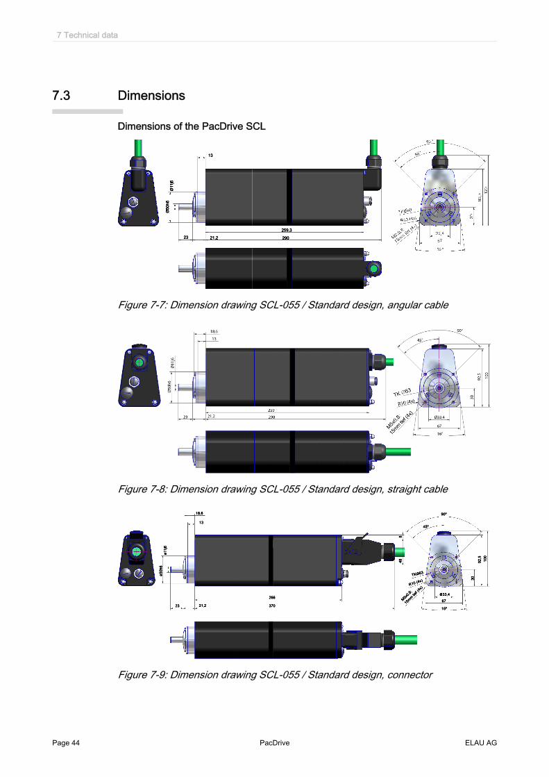
Dimensions of the PacDrive SCL
Figure 7-7: Dimension drawing SCL-055 / Standard design, angular cable
Figure 7-8: Dimension drawing SCL-055 / Standard design, straight cable
Figure 7-9: Dimension drawing SCL-055 / Standard design, connector
7 Technical data
Page 44 PacDrive ELAU AG

Figure 7-10: Dimension drawing SCL-055 / stainless steel design, straight cable
7.3 Dimensions
ELAU AG PacDrive Page 45

8 Appendix
8.1 Contact addresses
TrademarkPacDrive is a registered trademark of ELAU AG. All other trademarks named in this documentation are the sole property of their re‐spective manufacturer.ELAU AG DeutschlandDillberg 1297821 Marktheidenfeld, GermanyTel.: +49 (0) 9391 / 606 - 0Fax: 09391/606-300E-mail: [email protected]: www.elau.de
ELAU AG Customer ServicePostfach 1255 -97821 Marktheidenfeld, Germany97821 Marktheidenfeld, GermanyTel.: +49 (0) 9391 / 606 - 142Fax: +49 (0) 9391 / 606 - 340E-mail: [email protected]: www.elau.de
NOTECheck the ELAU homepage (www.elau.de) for additional contact addresses.
8.2 Product Training Courses
We also offer a number of training courses about our products.Our seminar leaders with several years of experience will help you take advantage ofthe extensive possibilities offered by the PacDrive™ system.
NOTECheck the ELAU homepage (www.elau.de) for further information and our currentseminar schedule.
8 Appendix
Page 46 PacDrive ELAU AG

8.3 Changes
NOTEThe latest product documentation, application notes and the change service are al‐ways available on the ELAU homepage.
07/2003
▪ New edition of the operating manual
12/2004
▪ Addition of Chapter SERCOS slaves▪ Addition of chapter Aseptic variants▪ Various error eliminations and additions▪ Layout change
01/2007
▪ Addition of stainless steel variant
03/2008
▪ Extension SCL-Type 30011▪ Changeover of type plates▪ Operating manual limited to SCL Standard and stainless steel variants▪ Chapter - Overview revised▪ Chapter - Installation & Maintenance revised▪ Type codes adjusted▪ Characteristic curves adjusted▪ Dimensional drawings revised
8.3 Changes
ELAU AG PacDrive Page 47

8.4 Fault report form
This error report is required without fail to enable efficient processing.
Send the error report to your ELAU AG-representativ or to:ELAU AGCustomer Service Department Dillberg 97828 Marktheidenfeld, Germany Fax: +49 (0)93 91 / 606 - 340Dillberg1297828 MarktheidenfeldFax: +49 (0) 93 91 / 606 - 340
Return address:
Company: City: Date:Department: Name: Tel.:
Specifications regarding product in questionItem name: ........................................................................Item no.: ...............................................................................Serial number: ..............................................................................Software version: .............................................................................Hardware code: ...............................................................................Parameters included Yes [ ] No [ ]IEC - Program included: Yes [ ] No [ ]
Information about machine on which the error occurred:Machine manufacturer: ......................................................................Type: .................................................................................................Operating hours: .............................................................................Machine no.: ..................................................................................Date of commissioning: ....................................................................Manufacturer / Type of machine control:........................................................................................................How did the error present:
........................................................................................................
........................................................................................................
........................................................................................................
Additional information:
8 Appendix
Page 48 PacDrive ELAU AG

Condition of error: Causes: Accompanying side effects:[ ] is always available [ ] unknown [ ] problems in the mechanism[ ] during commissioning [ ] wiring error [ ] power failure (24V)[ ] occurs sporadically [ ] mechan. damage damage damage [ ] controller failure[ ] occurs after approx. hours [ ] moisture in device [ ] motor failure[ ] occurs when shaken [ ] encoder defective [ ] broken cable[ ] depends on temperature [ ] insufficient ventilation[ ] contaminant in device
Is there an air conditioner in the switch cabinet? Y / N [ ]Have there been similar errors in the same axis previously? How often: ..............................Did the errors always occur on certain days or at certain times of day?........................................................................................................other information: ................................................................................................................................................................................................................ ........................................................................................................ ........................................................................................................ ........................................................................................................ ........................................................................................................ ........................................................................................................ ........................................................................................................ ........................................................................................................ ........................................................................................................ ........................................................................................................ ........................................................................................................ ........................................................................................................ ........................................................................................................
8.4 Fault report form
ELAU AG PacDrive Page 49

Index
CCleaning 27Configuration 24Contact addresses 46
DDefinitions 38Diagnosis 15Diagnosis Message 17
EELAU AG 2EMC Rules 25Error report 48
HHomepage 2, 46
LLegal notice 2
PPhysical connections 38Proper use 9
RRepairs 27Risk classification 7
SSeminars 46Service addresses 46Servicing 26Storage 18Symbols 7
TTrademark 2Training courses 46Type code 28
Index
Page 50 PacDrive ELAU AG