operating manual ver.1 - welcome to cgi bharatpur | cgi …cgibp.com/data/lab_manual/fourier...
TRANSCRIPT
Fourier Synthesis Trainer ST2603
Operating Manual Ver.1.1
An ISO 9001 : 2000 company
94-101, Electronic Complex Pardesipura, Indore- 452010, INDIA Ph: 91- 731- 2556638, 2570301 Fax: 91- 731- 2555643 E-mail : [email protected] Web: www.scientech.bz

ST2603
Scientech Technologies Pvt. Ltd. 2

ST2603
Scientech Technologies Pvt. Ltd. 3
Fourier Synthesis Trainer ST2603
Table of Contents 1. Introduction 4
2. Features 5 3. Technical Specifications 6
4. Operating Instructions & Panel Control Description 7 5. Theory 8
6. Experiments • Experiment 1 11
To construct a triangular wave with the help of fundamental frequency and its harmonic component
• Experiment 2 12 To construct a rectangular sawtooth wave with the help of fundamental frequency and its harmonic component
• Experiment 3 14 To construct a square wave with the help of fundamental Frequency and its harmonic component
• Experiment 4 16 To construct an absolute value sine wave with the help of fundamental frequency and its harmonic component
• Experiment 5 17 To construct Half sine wave with the help of fundamental Frequency and its harmonic component
• Experiment 6 19 To construct AM wave with the help of 3 frequency components
7. Glossary of Terminology 20
8. Warranty 22 9. List of Accessories 22

ST2603
Scientech Technologies Pvt. Ltd. 4
RoHS Compliance
Scientech Products are RoHS Complied. RoHS Directive concerns with the restrictive use of Hazardous substances (Pb, Cd, Cr, Hg, Br compounds) in electric and electronic equipments. Scientech products are “Lead Free” and “Environment Friendly”. It is mandatory that service engineers use lead free solder wire and use the soldering irons upto (25 W) that reach a temperature of 450°C at the tip as the melting temperature of the unleaded solder is higher than the leaded solder.
Introduction
Fourier synthesis is a method of electronically constructing a signal with a specific, desired periodic waveform. It works by combining a sine wave signal and sine wave or cosine-wave harmonics (signals at multiples of the lowest, or fundamental, frequency) in certain proportions. The scheme gets its name from a French mathematician and physicist named Jean Baptiste Joseph Baron de Fourier, who lived during the 18th and 19th centuries. ST2603, a unique FPGA based Fourier Synthesizer is a hardware trainer used to generate the waveform using harmonics. It is very useful in communication and DSP lab. Generation of standard time domain `wave forms Square, Sawtooth, Rectified sine, Modulated waveform etc are possible with the help of this trainer.
ST2603
Scientech Technologies Pvt. Ltd. 5
Features
• VLSI Based Training System
• On board digitally synthesized fundamental frequency & harmonics.
• On board DC Generators.
• Digitally controlled select switch for Harmonic.
• LCD Display for Harmonic measurement.
• On board Summing Amplifier.
• On board reset.
• Individual Gain Control.
• On board sine, Cosine selection.
• On board Phase Reversal provision.
• Built in Power Supply.
• Functional Blocks indicated on Mimic Board.
• Simulation Software for complete concept study.
ST2603
Scientech Technologies Pvt. Ltd. 6
Technical Specifications
Harmonic Generation Technique : Direct Digital Synthesis. Eleven Input Summing Amplifier : 1 No.
Fundamental Frequency : 1 KHz. Harmonics Generation : 9 Harmonics, ranges from 2 KHz to 10
KHz. Controllable gain for individual frequency component domain.
Digital Phase control of relative phases between fundamental and harmonics.
On Board Wave forms : 0°(sine), 90°(cosine), 180°(-sine), 270°(-cosine).
Waveform level (max) : 5Vpp (Approximately) Weight : 3 Kg (Approximately)
Dimension (mm) : W365 X D260 X H175 Power Requirement : 230V, +/-10%, 50Hz.
DC constant generation : -5V to +5V (approximately)

ST2603
Scientech Technologies Pvt. Ltd. 7
Operating Instructions and Panel Control Descriptions
The ST2603 Fourier Synthesis trainer is equipped with built in DC-Power supply, simply attach the three pin mains cord, supplied within the trainer to the three pin socket and connect the other end to a stable 230V AC supply.
A fuse (1A/250V) rating is connected in series with mains supply. When ‘On/Off’ switch of the trainer is turned ‘On’ the power indication will lit, indicating that the trainer is ‘On’. Fundamental frequency and its harmonics frequencies can be set to desired level (in the range 0-5V) with potentiometer given for each corresponding frequency. Toggle switches are provided for each frequency to generate phase shift of 0deg, 90deg, 180deg, 270deg. Left switch of each block provide shifting of 90deg therefore it is known as a sine to cosine shifting.
ST2603
Scientech Technologies Pvt. Ltd. 8
Theory Fourier Synthesis : A mathematical theorem stating that a Periodic function f(x) which is reasonably continuous may be expressed as the sum of a series of sine or cosine terms (called the Fourier series), each of which has specific Amplitude and Phase coefficients known as Fourier coefficients. The application of this theorem to sound is known as Fourier Analysis and Fourier Synthesis. The theorem was developed by the French mathematician J.B. Fourier around.1800. Many waveforms represent signal energy at a fundamental frequency and also at harmonic frequencies (whole-number multiples of the fundamental). The relative proportions of energy concentrated at the fundamental and harmonic frequencies determine the shape of the wave. The wave function (usually amplitude, frequency, or phase versus time) can be expressed as of a sum of sine and cosine functions called a Fourier series, uniquely defined by constants known as Fourier coefficients. If these coefficients are represented by a0, a1, a2, a3, ..., an, ... and b1, b2, b3, ..., bn ..., then the Fourier series F(x), where x is an independent variable (usually time), has the following form :
F(x) = a0/2 + a1 cos x + b1sin x + a2 cos 2x + b2 sin 2x + ... + an cos nx + bn sin nx +... In Fourier synthesis, it is necessary to know, or to determine, the coefficients a0, a1 a2, a3, ..., an ... and b1 b2, b3, ..., bn ... that will produce the waveform desired when "plugged into" the generalized formula for the Fourier series, as defined above. Then, sine and cosine waves with the proper amplitudes (as defined by the coefficients) must be electronically generated and combined, up to the highest possible value of n. The larger the value of n for which sine-wave and cosine-wave signals are generated, the more nearly the synthesized waveform matches the desired waveform. For e.g. following waveform shows the formation of sawtooth wave with the harmonic component.
Fourier synthesis is used in electronic music applications to generate waveforms that mimic the sounds of familiar musical instruments. It is also employed in laboratory instruments known as waveform generators or function generators. These devices are used to test communication systems. Although many musicians can create very clear -tones on their instruments, all instruments have their own characteristic voice. Voices are differentiated by the shape of their associated sound waves. All instrument voices display an array of frequencies which sum together to produce a wave of characteristic shape.
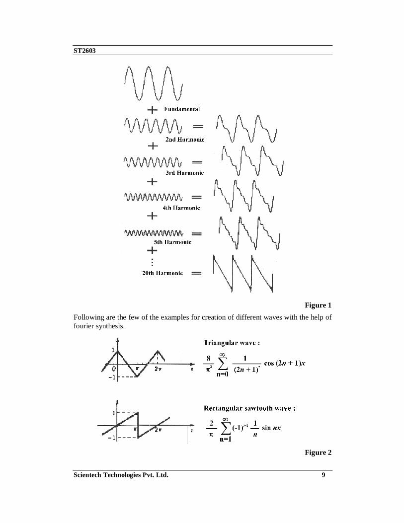
Following is the example for Successive approximations of a Sawtooth Wave by addition of harmonics with amplitude inversely proportional to the harmonic number. The resultant waveform at each stage of addition is shown at right.
ST2603
Scientech Technologies Pvt. Ltd. 9
Figure 1
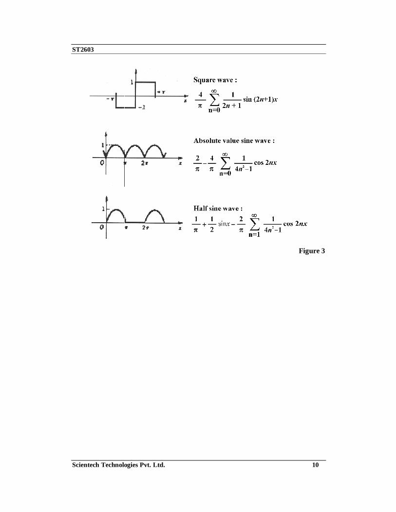
Following are the few of the examples for creation of different waves with the help of fourier synthesis.
Figure 2
ST2603
Scientech Technologies Pvt. Ltd. 10
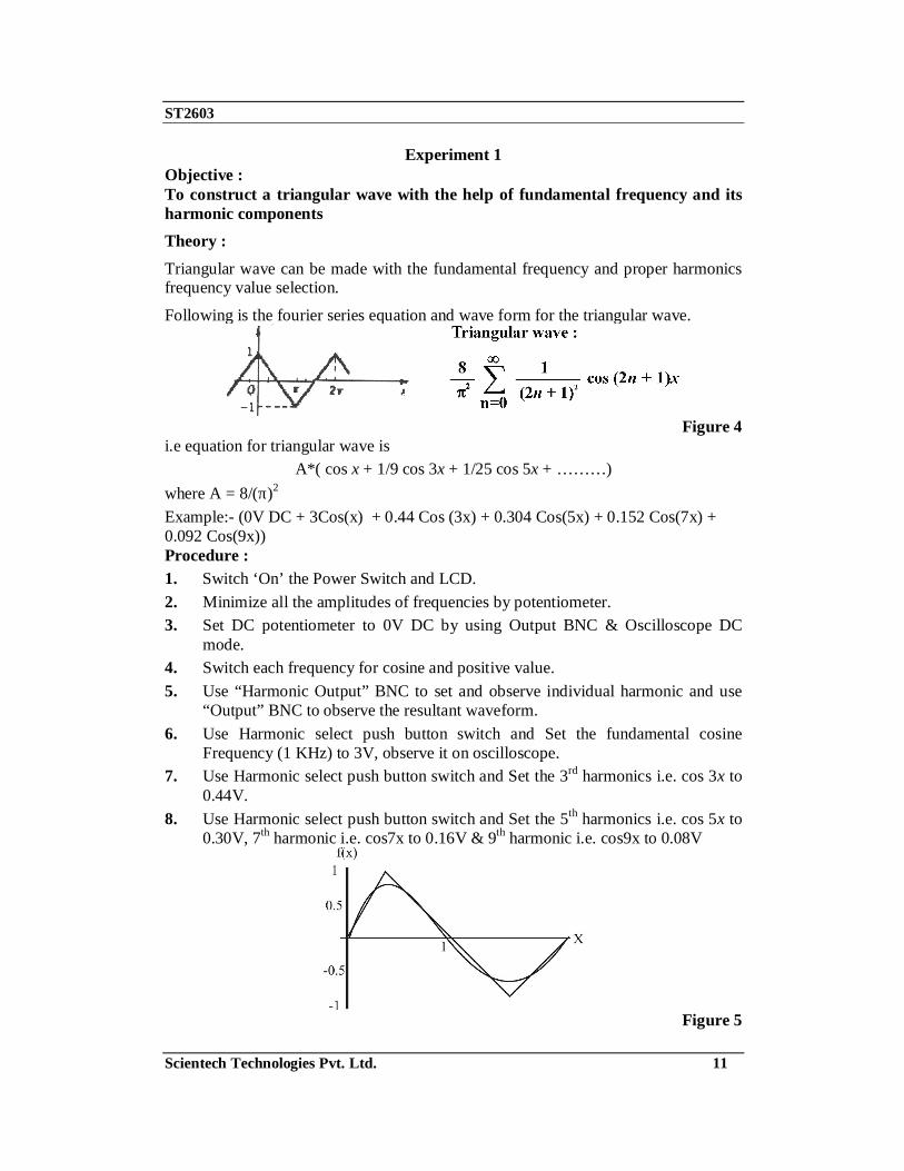
Figure 3
ST2603
Scientech Technologies Pvt. Ltd. 11
Experiment 1 Objective : To construct a triangular wave with the help of fundamental frequency and its harmonic components Theory : Triangular wave can be made with the fundamental frequency and proper harmonics frequency value selection.
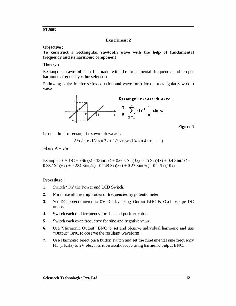
Following is the fourier series equation and wave form for the triangular wave.
Figure 4
i.e equation for triangular wave is A*( cos x + 1/9 cos 3x + 1/25 cos 5x + ………)
where A = 8/(π)2
Example:- (0V DC + 3Cos(x) + 0.44 Cos (3x) + 0.304 Cos(5x) + 0.152 Cos(7x) + 0.092 Cos(9x)) Procedure : 1. Switch ‘On’ the Power Switch and LCD. 2. Minimize all the amplitudes of frequencies by potentiometer. 3. Set DC potentiometer to 0V DC by using Output BNC & Oscilloscope DC
mode. 4. Switch each frequency for cosine and positive value. 5. Use “Harmonic Output” BNC to set and observe individual harmonic and use
“Output” BNC to observe the resultant waveform. 6. Use Harmonic select push button switch and Set the fundamental cosine
Frequency (1 KHz) to 3V, observe it on oscilloscope. 7. Use Harmonic select push button switch and Set the 3rd harmonics i.e. cos 3x to
0.44V. 8. Use Harmonic select push button switch and Set the 5th harmonics i.e. cos 5x to
0.30V, 7th harmonic i.e. cos7x to 0.16V & 9th harmonic i.e. cos9x to 0.08V
Figure 5
ST2603
Scientech Technologies Pvt. Ltd. 12
Experiment 2 Objective : To construct a rectangular sawtooth wave with the help of fundamental frequency and its harmonic component Theory : Rectangular sawtooth can be made with the fundamental frequency and proper harmonics frequency value selection. Following is the fourier series equation and wave form for the rectangular sawtooth wave.
Figure 6
i.e equation for rectangular sawtooth wave is
A*(sin x -1/2 sin 2x + 1/3 sin3x -1/4 sin 4x +…….)
where A = 2/π
Example:- 0V DC + 2Sin(x) - 1Sin(2x) + 0.668 Sin(3x) - 0.5 Sin(4x) + 0.4 Sin(5x) - 0.332 Sin(6x) + 0.284 Sin(7x) - 0.248 Sin(8x) + 0.22 Sin(9x) - 0.2 Sin(10x)
Procedure : 1. Switch ‘On’ the Power and LCD Switch.
2. Minimize all the amplitudes of frequencies by potentiometer. 3. Set DC potentiometer to 0V DC by using Output BNC & Oscilloscope DC
mode. 4. Switch each odd frequency for sine and positive value.
5. Switch each even frequency for sine and negative value. 6. Use “Harmonic Output” BNC to set and observe individual harmonic and use
“Output” BNC to observe the resultant waveform. 7. Use Harmonic select push button switch and set the fundamental sine frequency
H1 (1 KHz) to 2V observes it on oscilloscope using harmonic output BNC.
ST2603
Scientech Technologies Pvt. Ltd. 13
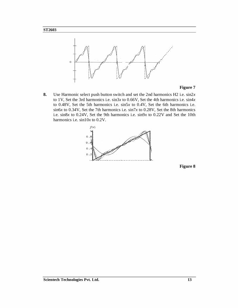
Figure 7
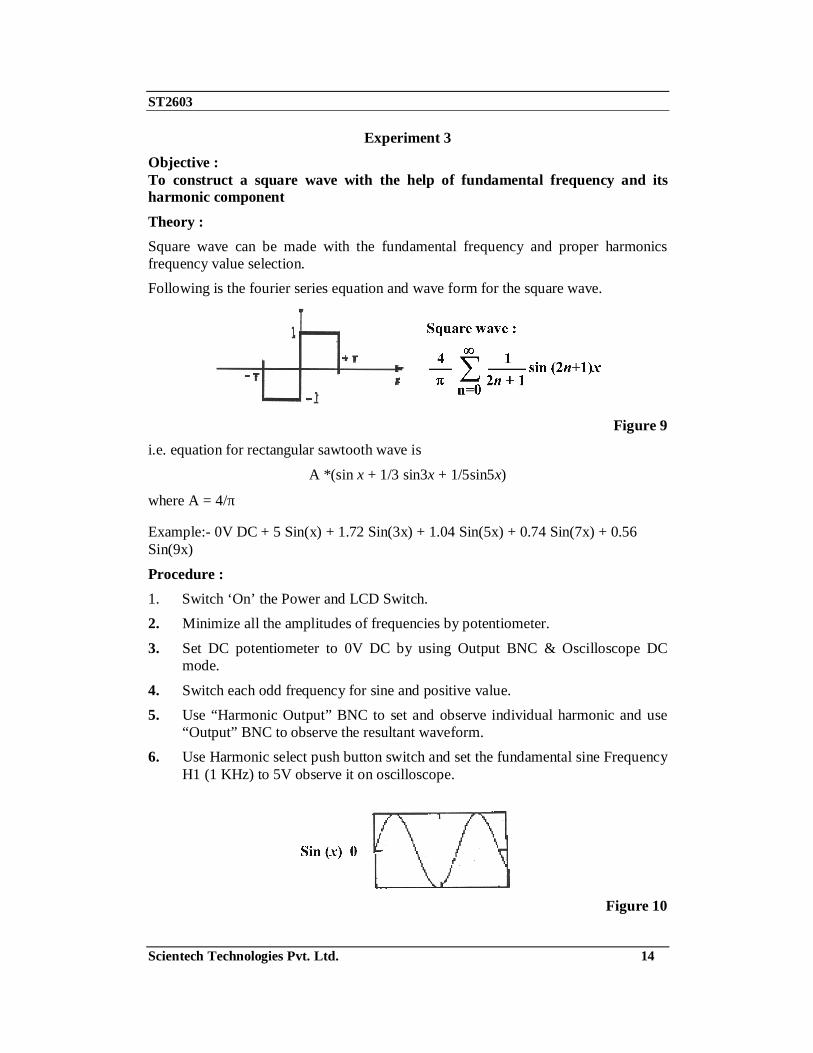
8. Use Harmonic select push button switch and set the 2nd harmonics H2 i.e. sin2x to 1V, Set the 3rd harmonics i.e. sin3x to 0.66V, Set the 4th harmonics i.e. sin4x to 0.48V, Set the 5th harmonics i.e. sin5x to 0.4V, Set the 6th harmonics i.e. sin6x to 0.34V, Set the 7th harmonics i.e. sin7x to 0.28V, Set the 8th harmonics i.e. sin8x to 0.24V, Set the 9th harmonics i.e. sin9x to 0.22V and Set the 10th harmonics i.e. sin10x to 0.2V.
Figure 8
ST2603
Scientech Technologies Pvt. Ltd. 14
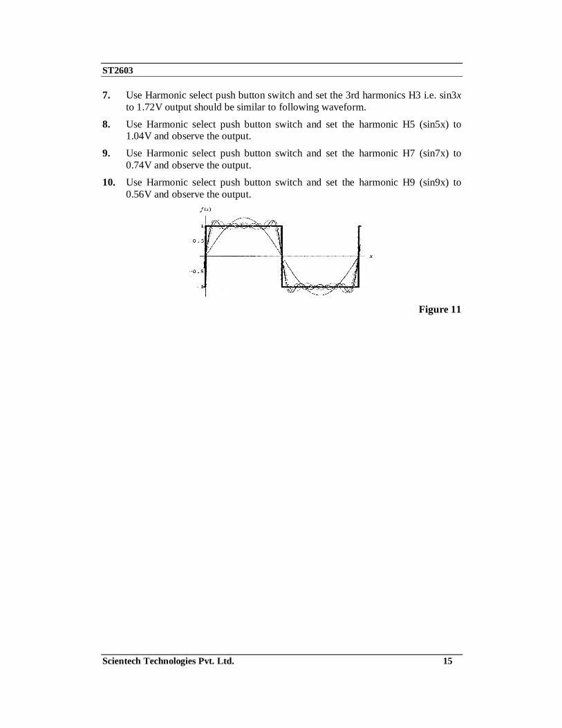
Experiment 3 Objective : To construct a square wave with the help of fundamental frequency and its harmonic component Theory : Square wave can be made with the fundamental frequency and proper harmonics frequency value selection. Following is the fourier series equation and wave form for the square wave.
Figure 9
i.e. equation for rectangular sawtooth wave is
A *(sin x + 1/3 sin3x + 1/5sin5x)
where A = 4/π Example:- 0V DC + 5 Sin(x) + 1.72 Sin(3x) + 1.04 Sin(5x) + 0.74 Sin(7x) + 0.56 Sin(9x)
Procedure : 1. Switch ‘On’ the Power and LCD Switch. 2. Minimize all the amplitudes of frequencies by potentiometer.
3. Set DC potentiometer to 0V DC by using Output BNC & Oscilloscope DC mode.
4. Switch each odd frequency for sine and positive value. 5. Use “Harmonic Output” BNC to set and observe individual harmonic and use
“Output” BNC to observe the resultant waveform. 6. Use Harmonic select push button switch and set the fundamental sine Frequency
H1 (1 KHz) to 5V observe it on oscilloscope.
Figure 10
ST2603
Scientech Technologies Pvt. Ltd. 15
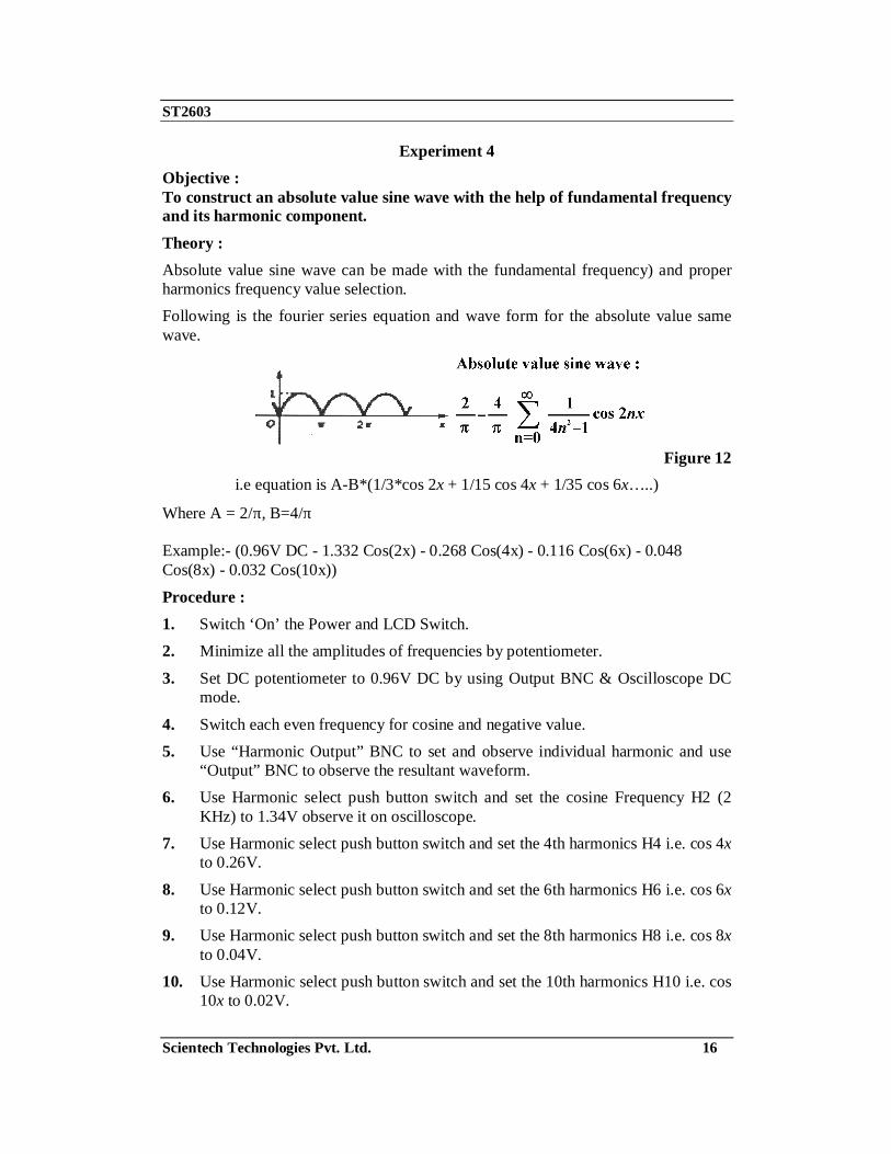
7. Use Harmonic select push button switch and set the 3rd harmonics H3 i.e. sin3x to 1.72V output should be similar to following waveform.
8. Use Harmonic select push button switch and set the harmonic H5 (sin5x) to 1.04V and observe the output.
9. Use Harmonic select push button switch and set the harmonic H7 (sin7x) to 0.74V and observe the output.
10. Use Harmonic select push button switch and set the harmonic H9 (sin9x) to 0.56V and observe the output.
Figure 11
ST2603
Scientech Technologies Pvt. Ltd. 16
Experiment 4 Objective : To construct an absolute value sine wave with the help of fundamental frequency and its harmonic component. Theory : Absolute value sine wave can be made with the fundamental frequency) and proper harmonics frequency value selection. Following is the fourier series equation and wave form for the absolute value same wave.
Figure 12
i.e equation is A-B*(1/3*cos 2x + 1/15 cos 4x + 1/35 cos 6x…..)
Where A = 2/π, B=4/π Example:- (0.96V DC - 1.332 Cos(2x) - 0.268 Cos(4x) - 0.116 Cos(6x) - 0.048 Cos(8x) - 0.032 Cos(10x))
Procedure : 1. Switch ‘On’ the Power and LCD Switch. 2. Minimize all the amplitudes of frequencies by potentiometer.
3. Set DC potentiometer to 0.96V DC by using Output BNC & Oscilloscope DC mode.
4. Switch each even frequency for cosine and negative value. 5. Use “Harmonic Output” BNC to set and observe individual harmonic and use
“Output” BNC to observe the resultant waveform. 6. Use Harmonic select push button switch and set the cosine Frequency H2 (2
KHz) to 1.34V observe it on oscilloscope. 7. Use Harmonic select push button switch and set the 4th harmonics H4 i.e. cos 4x
to 0.26V.
8. Use Harmonic select push button switch and set the 6th harmonics H6 i.e. cos 6x to 0.12V.
9. Use Harmonic select push button switch and set the 8th harmonics H8 i.e. cos 8x to 0.04V.
10. Use Harmonic select push button switch and set the 10th harmonics H10 i.e. cos 10x to 0.02V.

ST2603
Scientech Technologies Pvt. Ltd. 17
Experiment 5 Objective : To construct Half sine wave with the help of fundamental frequency and its harmonic component. Theory : Half sine wave can be made with the fundamental frequency and proper harmonics frequency value selection. Following is the fourier series equation and wave form for the Half sine wave.
Figure 13 i.e equation is
A+B*sinx-C*(1/3*cos 2x + 1/15 cos 4x + 1/35 cos 6x ...)
where A = 1/π , B = 1/2 , C = 2/π Example:- (0.984V DC + 3.064 Sin(x) - 1.332 Cos(2x) - 0.268 Cos(4x) - 0.116 Cos(6x) - 0.048 Cos(8x) - 0.032 Cos(10x))
Procedure : 1. Switch ‘On’ the Power and LCD Switch.
2. Minimize all the amplitudes of frequencies by potentiometer. 3. Set DC potentiometer to 0.96V DC by using Output BNC & Oscilloscope DC
mode. 4. Switch each even frequency for cosine and negative value.
5. Switch frequency H1 to sine and positive value. 6. Use “Harmonic Output” BNC to set and observe individual harmonic and use
“Output” BNC to observe the resultant waveform.
7. Use Harmonic select push button switch and set the sine Frequency H1 (1 KHz) to 3.06V.
8. Use Harmonic select push button switch and set the cosine Frequency H2 (2 KHz) to 1.34V observe it on oscilloscope.
ST2603
Scientech Technologies Pvt. Ltd. 18
9. Use Harmonic select push button switch and set the 4th harmonics H4 i.e. cos 4x to 0.26V.
10. Use Harmonic select push button switch and set the 6th harmonics H6 i.e. cos 6x to 0.12V.
11. Use Harmonic select push button switch and set the 8th harmonics H8 i.e. cos 8x to 0.04V.
12. Use Harmonic select push button switch and set the 10th harmonics H10 i.e. cos 10x to 0.02V.
ST2603
Scientech Technologies Pvt. Ltd. 19
Experiment 6 Objective : To construct AM wave with the help of 3 frequency components Theory : 0V DC + 2 Sin(6x) + 4 Sin(7x) + 2 Sin(8x) Procedure : 1. Switch ‘On’ the Power and LCD Switch. 2. Minimize all the amplitudes of frequencies by potentiometer.
3. Set DC potentiometer to 0V DC by using Output BNC & Oscilloscope DC mode.
4. Switch all frequency for sine and positive value. 5. Use “Harmonic Output” BNC to set and observe individual harmonic and use
“Output” BNC to observe the resultant waveform. 6. Use Harmonic select push button switch and set the 6th harmonics H6 i.e.
sine6x to 2V. 7. Use Harmonic select push button switch and set the sine Frequency 7th harmonic
H7 (7 KHz) to 4V observe it on oscilloscope. 8. Use Harmonic select push button switch and set the 8th harmonics H8 i.e.
sine8x to 2V.

ST2603
Scientech Technologies Pvt. Ltd. 20
Glossary Amplitude : The amplitude of a wave is the distance of maximum displacement of a point on the wave. Period : The characteristic ascribed to a variable which repeats any value it attains at regular intervals of time called a Period.
Phase : In electronic signaling, phase is a definition of the position of a point in time (instant) on a waveform cycle. A complete cycle is defined as 360 degrees of phase as shown in Illustration A below. Phase can also be an expression of relative displacement between or among waves having the same frequency. The wave depicted by the dashed line leads the wave represented by the solid line by 90 degrees.
Figure 14
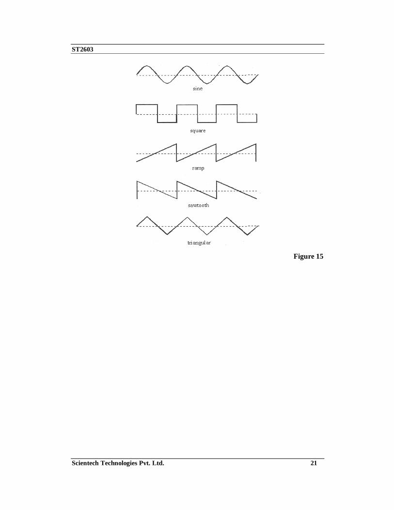
Frequency : For an oscillating or varying current, frequency is the number of complete cycles per second in alternating current direction. The standard unit of frequency is the hertz, abbreviated Hz. If a current completes one cycle per second, then the frequency is 1 Hz. Larger units of frequency include the kilohertz (KHz) representing thousands (1,000's) of cycles per second, the megahertz (MHz) representing millions (1,000,000's) of cycles per second, and the gigahertz (GHz) representing billions (1,000,000,000's) of cycles per second. Occasionally the terahertz (THz) is used; 1 THz = 1,000,000,000,000 cycles per second. Waveform : A waveform is a representation of how alternating current (AC) varies with time. The most familiar AC waveform is the sine wave, which derives its name from the fact that the current or voltage varies with the sine of the elapsed time. Other common AC waveforms are the square wave, the ramp, the sawtooth wave, and the triangular wave. Their general shapes are shown below.
ST2603
Scientech Technologies Pvt. Ltd. 21
Figure 15
ST2603
Scientech Technologies Pvt. Ltd. 22
Warranty 1. We guarantee the product against all manufacturing defects for 24 months from
the date of sale by us or through our dealers. Consumables like dry cell etc. are not covered under warranty.
2. The guarantee will become void, if
a) The product is not operated as per the instruction given in the operating manual.
b) The agreed payment terms and other conditions of sale are not followed.
c) The customer resells the instrument to another party. d) Any attempt is made to service and modify the instrument.
3. The non-working of the product is to be communicated to us immediately giving full details of the complaints and defects noticed specifically mentioning the type, serial number of the product and date of purchase etc.
4. The repair work will be carried out, provided the product is dispatched securely packed and insured. The transportation charges shall be borne by the customer.
List of Accessories
1. Mains Cord ............................................................................................1 No. 2. BNC to BNC Cable.................................................................................1 No.
3. e-Manual (Simulation Software inclusive) ..............................................1 No.