operating systems notes - webs€¦ · web viewcpu scheduling: - cpu scheduling is a basic...
TRANSCRIPT

Operating Systems Notes
Chapter – 1
HISTORY OF THE OPERATING SYSTEMS
Zeroth Generation: -
Charles Babbage designed the first digital computer. It used some mechanical parts like wheels, gears, etc. It was slow and UN reliable. There was no operating system for this type of computer.
First Generation: - (1945-55)
Akien, van nenumeann & Others Succeeded in designing calculating machines with vaccum tubes as central components.
These vacuum tubes generate heat and they huge in size. The programming was done in machine language. (First Generation Language) There were no Operating Systems. These machine were Single-User and were extremely unfriendly to User / Programmers.
Second Generation: -(1955-65)
Transistor replaced the vaccum tubes. Hence the size and the cost of the machine were reduced.
$ JOB
$ END
DATA
$ RUN
FORTRAN PROG
$ LOAD
$JOB: USER
Next Job
Data Cards
Control Cards
Program Cards
Structure of batch job

Assembly Language (2Gl) and FORTRAN emerged during this period. Concept of Batch Job was introduced. But the CPU time was wasted as the user himself had to identify the end of job discount (“Teardown Operation”) it and mount the tapes cards for the next job (“Setup Operation”). This problem was rectified in the later periods in IBM-7094 (satellite Computer).
The machines were Single User. Master Control Program (MCP) operating system was produced which had the features of Multi-programming, Multi-processing and Virtual Storage.
Third Generation: (1965-80)
IBM / 360 series were announced which were based on IC’s rather then transistors.
The cost and the size of the computer reduced to the greater extent and the performance was improved at the same time.
The Major features and problems of this computer (IBM / 360) and its operating systems. Were
(a) Integrated Circuits: -Reduces the size of the computer improved the performance.
(b) Protability: -The Operating Systems were written Assembly Language. The routines
were complex and time-consuming. As the operating systems were written for
Tape-B
Tape-A
Tape-P
Tape-J
7094 Controls
7094 actually processes the job
a specific machine, they were not easily protable to machine with different architecture.
(c) Job Control Language: -
JCL was developed to allow communication between the User / Programmer. Hence the interruption is decreased. By using JCL, a user / programmer could instruct the computer and its OS to perform the tasks in a specific sequence.
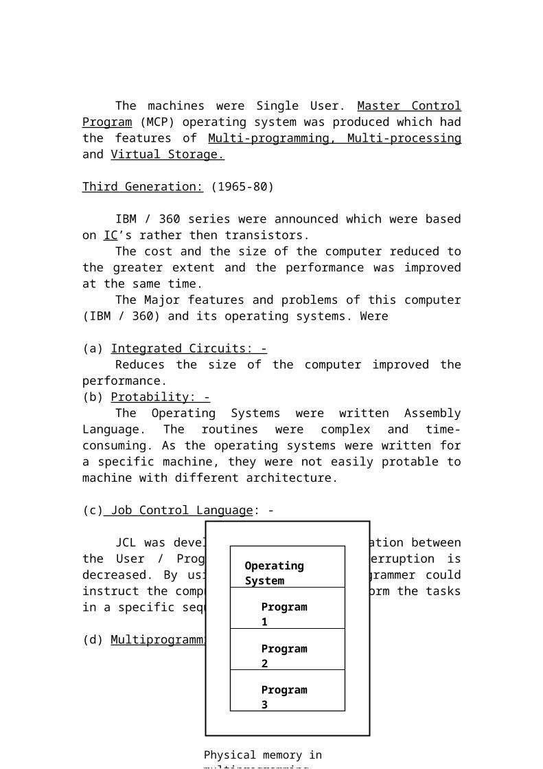
(d) Multiprogramming: -
The physical memory was divided in to many partitions. Each partitions holding a separate program.
In a Uniprogramming environment, the CPU was idle when any I/O for any program was going on, But in a multiprogramming environment, when I/O for a program was going on the CPU switched to other program for processing and hence the increase in throughput was achieved.
(e) SPOOLING: - (Simultaneously Peripheral Operations On-Line)
All the jobs could be read in to the disk first and OS would load as many jobs in the available memory could accommodate them. After many programs were loaded in different partitions of the memory, the CPU was switching from one program to another program to achieve multiprogramming.
Operating System
Program 1
Program 2
Program 3
Physical memory in multiprogramming

Advantages:
1. It allowed smooth multiprogramming operations.2. All the I/O of all the jobs was essentially pooled together in the
spooling method and therefore, this could be overlapped with the CPU bound computations of all the jobs at appropriate time chosen by the OS to improve the Throughput.
(f) Time Sharing: -
It enhances the multiprogramming using software called “Scheduler” the OS is able to identify the higher priority process with the ordinary process.
IBM first gives its user a program called “Customer Information Control Systems “ (CICS) which provided Data communication between the terminalsand the computer. Scheduled various inter active user jobs the CICS function as a “Transaction Processing Monitor” (TP), “Time Sharing Option” (TSO) software deals with scheduling.
Compatible Time Sharing System (CTSS) was the first time sharing system. Multiplexed Information and Computing Service (MULTICS) was the next to CTSS.
Fourth Generation: - (1980-90)
Large Scale Integration Circuit came in to existence. Thousands of transistors could be package on a very small area of a Silicon Chip.
Cards Report
Disk
a cb
Spooling
d
Control Program for Micro Computer (CP/M) was the OS on the microcomputer platform. It is Single user OS. It was developed on Intel 8080 (User friendly).
Multi Program for Micro Computer MP/M was a 16bit multi-user, time-sharing OS. CP/NET was released to provide Networking Capatilities with MP/M as the server to serve the requests received from other CP/M machines.
In Intel 8086, IBM had released PC-DOS operating systems and Microsoft released MS-DOS as its OS.
Q DOS, another OS was potential than CP/M which later because PC-DOS & MS-DOS.So many other OS with their different features were introduced. UNIX, XENIX, OS/2Were released.
In 386 and 486 computers, bit mapped graphic displays became faster and hence Graphical user Interface (GUI) became popular. MS-WINDOWS is a user-friendly graphical user interface.
MS-WINDOWS did not level a true multitasking capability to the OS.WINDOWS NT incorporated this capability.
When the concept of ‘Distributed Processing’ became a reality, there arose a need for an OS. Which satisfy this Network Operating System (NOS) and Distributed Operating System (DOS) satisfied this needs.
The difference between NOS and DOS is, NOS the users are aware that there are several computers connected to each other Via a network.Eg: -
Novell’s Netware
DOS makes the whole network transparent to the user1. All the resources are shared amongst a no of user’s who are not a
ware of such sharing.
MP / MCP / NET
CP / M
CP / M
CP / M
File Server
Node
Node
Node

2. DOS allow Parallelism i.e., a program can be segmented into different machines.
3. The OS must hide the hardware differences which exist in different computers connected to each other,
4. It should provide high level of fault tolerance i.e. if one computer is down the OS could schedule the tasks on the other computers.
Chapter – 2
OPERATING SYSTEM FUNCTIONS
What is an Operating System?“The OS is a set of software programs supplied along with the Hardware
for the effective and easy use of machine “.
Benefits of OS: - Provision security / confidentiality of information. Elimination of duplicate effects by programmers for developing tedious
routines.
Security: -The OS takes care of allocating / deallocating the storage are a on the
disk for different user for different files. It secures the data form overwriting on the same sector OS instruct the Hardware to write data from memory onto a pre-specified locating on the disk. The OS provides a no of system calls to perform various I / O functions such as read, write, open, close, seek, etc. The complied program must contain these system calls to get the I / O task to be alone.
Confidentiality: -The OS helps in maintaining the privacy there by protecting the
unauthorized access to file, by the external code or user.
Elimination of duplicate effects: -Once the as developers write the routines for all the I/O operation each
application programmer does not have to code them again & again. They’re by the programmers.
When the application program writes “Read / Write Instructions”, the complier generates the appropriate system calls in their place and at the time of execution, the OS carries out the instructions on behalf of Applications using the appropriate routines already developed.
Direct Memory Access: -It is the hardware unit, which consists of its own memory and
instruction set to take care of the I/O operations.It needs an instruction specifying the address of the sector(s), which is to
be read, and the memory location where it is to be written. When the OS supplies this instruction to the controller, the controller can carry out the data Transfer on its own, without the help of the main CPU.
CPU is free to execute any other any other program when the I/O is going on for some other program.
The operation of transferring the data directly by the controller without the help of CPU is called Direct Memory Access and the controller is called DMA controller. DMA forms a very important basis for a multi-user, multi Programming OS.
Steps in Multi Programming: -
1. Application program (AP-1) contains an instruction of the type “READ CUSTOMER-FILE At end”.
2. Complier generates a systems call for this instruction.3. At this time of execution, when this system call is encountered, AP-1
is blocked (Until I/O is Over). The OS then schedules another program (AP-2) for execution.
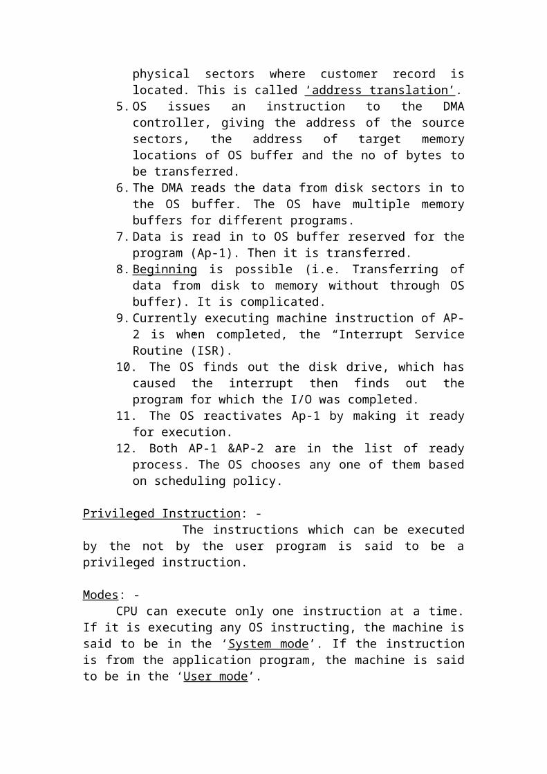
4. OS takes up AP-1, while CPU takes up AP-2 for execution. OS finds out the address of the physical sectors where customer record is located. This is called ‘address translation’.
5. OS issues an instruction to the DMA controller, giving the address of the source sectors, the address of target memory locations of OS buffer and the no of bytes to be transferred.
6. The DMA reads the data from disk sectors in to the OS buffer. The OS have multiple memory buffers for different programs.
7. Data is read in to OS buffer reserved for the program (Ap-1). Then it is transferred.
8. Beginning is possible (i.e. Transferring of data from disk to memory without through OS buffer). It is complicated.
9. Currently executing machine instruction of AP-2 is when completed, the “Interrupt Service Routine”(ISR).
10. The OS finds out the disk drive, which has caused the interrupt then finds out the program for which the I/O was completed.
11. The OS reactivates Ap-1 by making it ready for execution.12. Both AP-1 &AP-2 are in the list of ready process. The OS chooses
any one of them based on scheduling policy.
Privileged Instruction: - The instructions which can be executed by the not by the user program is said to be a privileged instruction.

Modes: -CPU can execute only one instruction at a time. If it is executing any OS
instructing, the machine is said to be in the ‘System mode’. If the instruction is from the application program, the machine is said to be in the ‘User mode’.
Different services of OS: -
Information Management (IM) Process Management (PM) Memory Management (MM)
Information Management : -It refers to a set of service user storing, retrieving, modifying or removing the information or various devices.The IM organizes the information as directories and files allocate and reallocate the sectors to various files and enforcing the access controller is managed by it.
Some of the calls in this category are
1. Create a file.2. Create a directory.3. Open a file (read, write, etc).4. Close a file.5. Read data form file to buffer.6. Write data form buffer to disk.7. Move the file Pointer.8. Read data return a file’s status.9. Create a pipe.10. Create a link11. Change working directory.
Process Management : -The services provided by PM are very important, if the OS is a multi-user OS. It is less significant in a single user, Uniprogramming environment.
Some of the system calls in this category are: -
1. Create a child process identical to parent.2. Wait for child process to terminate.3. Terminate a process.4. Change the priority of a process.5. Block a process.6. Ready a process.7. Dispatch a process.
8. Suspend a process.9. Resume a process.10. Delay a process.11. Fork a process.
Memory Management : -(MM)
The services provided by MM are to keep track of memory and allocating / reallocating it to various process. The OS keeps a list of free memory locations.
When the program is loaded in the memory from the disk, this module (MM) consults this free list, allocates the memory to the process, depending upon the program size and updates the list of free memory.
Some of the system calls in this category are: -
1. Allocates a chunk of memory to a process.2. Free a chunk of memory from a process.
User Of System Calls: -
In the some HLL such as PL/1, C the system calls are embedded in theMidst of the statements. This makes then more suitable for writing or system Software.
In some other HLL, the complier at proper places substitutes these system calls, wherever necessary. For Example: - When there is a STOPRUN statement, the complier substitutes it by a system call to “Kill or Terminate the Process”.
The compliers for same language under two different OS, a Substitutes different set of OS calls for the same source statements. The format, functionality, scope, parameters passed and returned results or errors differ quite a lot between the two OS.
The Issue Of Portability: - When the same complied binary program id executed in different
architecture computer, it will not be executed properly as the instruction set differs to a greater extent.
Example: -When a COBOL programming is complied under U NIX on PC / AT. It
cannot be run on a VAX machine under UNIX.When we take Tue it complied binary program to the same machine but
under different OS, it will not execute properly as the system calls are completely different.
Example: -COBOL under MS-DOS on a PC / AT cannot run directly under UNIX
on the same PC / AT. It needs recompilation.Object Code Portability is achievable only if the instruction set of the
machine as well as the OS is same.Source Code Portability can be achieved by allowing the same source
statements for two different compliers for different machines / OS combinations.
User View Of The OS: -OS is a set of Command Interpreter. These command interpreter (CI)
constitutes command language (CL). Which is otherwise called a user Interface. Some of the facilities provided by CL are,
Create a file in a directory. Delete a file from a directory. Copy a file. Compile a program. Link all the procedures in a program. Execute a linked program. Format a disk. List the contents of a directory. Type the contents of a file on the terminal. Abort a running program.
CI consists of a set of programs, one for each of the commands.Eg: - These are program for creating a file in a directory and another for executing a program and so on.
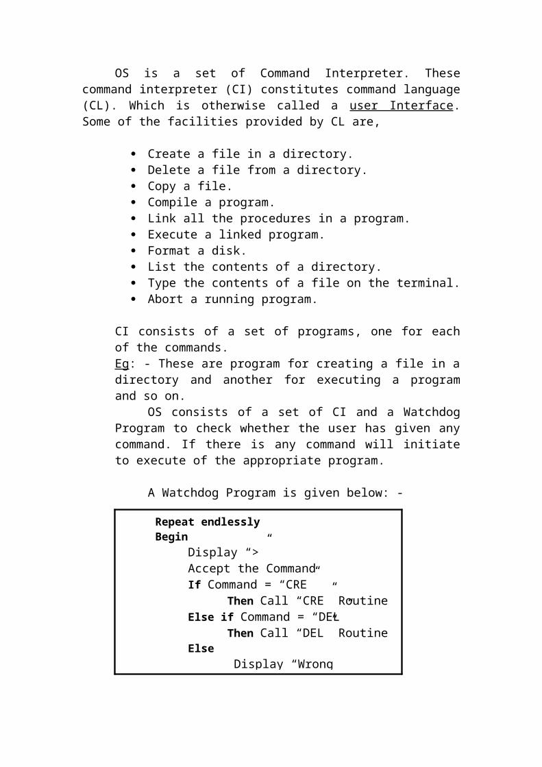
OS consists of a set of CI and a Watchdog Program to check whether the user has given any command. If there is any command will initiate to execute of the appropriate program.
A Watchdog Program is given below: -
Repeat endlesslyBegin
Display “>”Accept the CommandIf Command = “CRE” Then Call “CRE” RoutineElse if Command = “DEL” Then Call “DEL” RoutineElse Display “Wrong Command”End if
End

As soon as the user types in any command, this watchdog program checks whether it is one of the valid commands, and it so executes the particular program corresponding to that command.
If the command is invalid, the watchdog displays an error message and prompts for a now command.
An Example for the execution of a command “RUN” is given below.
> RUN Payroll.
“RUN” is equivalent to execute command is same OS. Steps involved in executing this command are
1. CI Watchdog Prompt “>” a screen and waits for the response.2. When the user types “RUN Payroll”. This command is transferred
from the CI for analysis.3. The CI Watchdog Program examines the command and finals
whether the command “RUN” is valid or not. The parameter passed to the command is PAYROLL.
4. The RUN routine, with the help of a system call in the IM category locates a file and finals out its size.
5. The RUN routine, with the help of a system calls is the MM category checks whether is free memory available to accommodate this program, and if available “MM” allocates memory to this program. If not, displays an error message and waits or terminates depending upon the policy.
6. If there is sufficient memory, with the help of a system call in the IM category, it actually transfers the complied program from the disk into these available memory locations.
7. It now issues a system call in the PM category to schedule and execute this program.
The Significant points to be noted are,
The system calls in the IM; PM & MM categories have to work in close Co-operation with one another.
The commands are executed with the help of a variety of system calls inter-nally.
Macro Facility: -
The CL provide for a Macro facility, which allows the user to create a list of commands and store then in a file.
Macro facility is called

Shell script in UNIX,CLI MACRO is AOS/VS,DCL procedures in VAX/VMS.
Graphical User Interface: -(GUI)
It provides various menus with colours, graphics and windows the user does not love to remember tedious syntaxes of the command language, but can point at a chosen option by means of a mouse. The position of the mouse is translated into the co-ordinates or the position of the cursor on the screen. The CI watchdog program maintains a table of routines and the possible screen positions of a cursor manipulated by the mouse. When the user clicks at a certain mouse position, the OS invokes the corresponding routine; The OS essentially refer to the table to translate this screen position in to the correct option, and then calls the specific routine.
The Kernel: -
The OS is a complicated piece of software. It consists of a number of routines. The OS is very large and it cannot be loaded fully as it leaves only small area for the application programs.
Hence the OS is divided into two parts. One consists of the very essential routines, which are required more often and almost all the time, and the other consists of routines, which are required some times.
The vital portion called the kernel of the OS. This is innermost layer of the OS close to the hardware and controlling the actual hardware. It is the heart of OS.
Booting: -The loading of the OS is achieved by a specific program called BOOT,
which is stored in one (two) sectors on the disk with a predetermined address. This portion is called “BOOT BLOCK”. The ROM normally contains a
KERNEL
Other O/S routine if required or other A/P
A/P
Other routines
Kernel of the operating system

minimum program, which transfers the control to this program (when the computer is turned on) automatically by the hardware. The program is a ROM loads the Boot program in predetermined memory, which in turn loads the rest of the OS into the memory.
The mechanism of pulling oneself up is called boot strapping or booting.
Computer virus may result in affecting the boot block, so that either OS will not be loaded or may produce unpredictable result.
Information Management: -
Highlights on File System (FS) Block Address Translation Relationship between AP, OS, DMS & H/W
BOOT
Memory
Remaining part of the operating system
System disk
Boot Block
The H/W loads the BOOT routine automatically
BOOT
Memory System disk
The BOOT routine loads the rest of the OS
Disk space allocation1. Contiguous2. Chained3. Indexed
Hierarchical file system Device drivers
1. I/O Procedures 2. I/O Schedulers3. Device Handler4. ISR (Interrupt Service Routine)
Information management consists of two main modules,1. File System (FS).2. Device Driver (DD) or Device Management (DM).
Block: -
A block is a logical unit of data that the OS defines for its convenience.A block may be equal to a sector or may be twice or 4 times as big OS a sector.
A sector is a physical unit of data on the disk, for the make of convenience; the block size is normally an exact multiple of sector size.
A block is not a unit of data transferred between the disk and the main memory.
A block is not a unit of data to which the disk space is allocated to files.A block is not a logical record.
When the file is transferred between the disk and memory, the OS expects the AP to Supply.
a) File IDb) Starting position in the filec) Number of bytes to be readd) Starting address of memory
where the data is to be read.
FILE SYSTEM
A file is a collection of resource of a similar type of information.Eg: Employee file, Electricity bill file.
If we want to perform various manual functions, the computer must provide a facility for a user to define and files increases various files of the same type will be put under one directory. Eg: All files containing data about sales could be put under sales directory.
A directory can be considered as a file of files. The application program needs various services for these files as well as directories such as
1. Open a file 2. Create a file 3. Delete a directory Etc.
This is done by file system again using a series if system calls.
ARCHITECTURE OF A HARDDISK: -
The OS looks at a hard disk as a series of sectors and numbers them serially starting from 0.
If has 2 cylinders (inner & outer cylinder) and having two surfaces has several sectors.
So the address can be considered as having 3 components such as cylinder number, surface number and sector number.
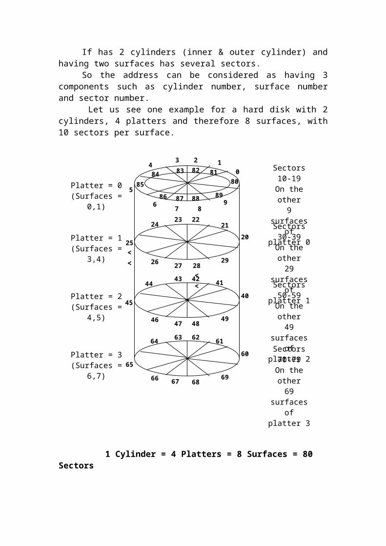
Let us see one example for a hard disk with 2 cylinders, 4 platters and therefore 8 surfaces, with 10 sectors per surface.
1 Cylinder = 4 Platters = 8 Surfaces = 80 Sectors
Platter = 0(Surfaces = 0,1)
Platter = 1(Surfaces = 3,4)
Platter = 2(Surfaces = 4,5)
Platter = 3(Surfaces = 6,7)
Sectors 10-19On the other9 surfaces of
platter 0
Sectors 30-39On the other29 surfaces of platter 1
Sectors 50-59On the other49 surfaces of platter 2
Sectors 70-79On the other69 surfaces of platter 3
012
43
5
67 8
9
80
83 818284
86
85
87 8988
20
212422
25<<
23
26 2927 28
<<
40
4143
45
4442
4849
4746
67 6866
65
64 6263
69
61
60
The numbering starts with 0 at the outer most cylinders and top most surfaces. Each sectors a numbered anticlockwise, so that if the disk rotates clockwise, it will encounter sectors 0,1,2,3,4,etc.
When all sectors on that surface on that cylinder are numbered, the next surface below on the same platter on the same cylinder will be numbered. After both the surfaces of one platter are over, the other platters for the same cylinder are continued. After the full cylinder is over, we go to the inner cylinder, and continue from the top surface.
In our example, the above hard disk is having 2 cylinders, [(i.e.) innermost cylinder (cylinder 1), outermost cylinder (cylinder 0) ],4 platters with 2 surfaces for each platter [totally 8 surfaces] and sectors 0-79on outermost cylinder, sectors 80-159 on innermost cylinder.
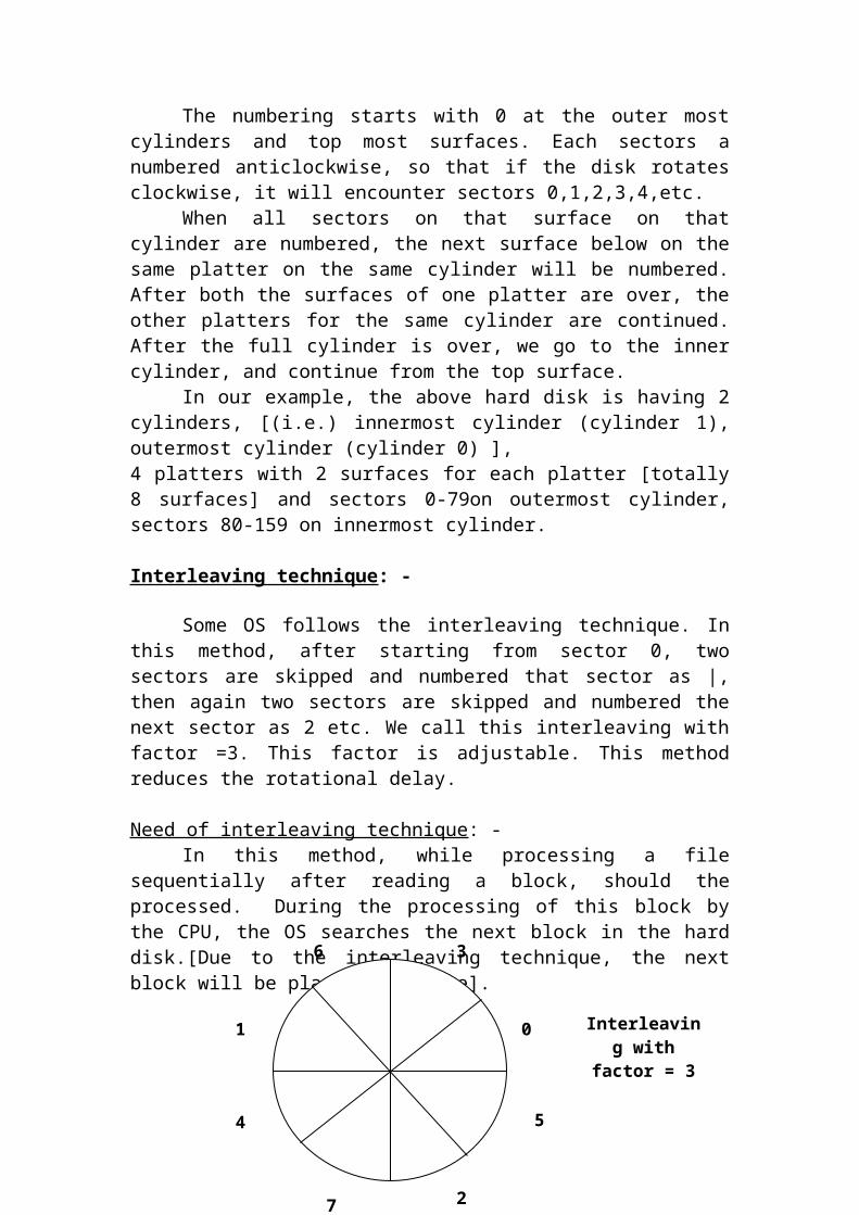
Interleaving technique: -
Some OS follows the interleaving technique. In this method, after starting from sector 0, two sectors are skipped and numbered that sector as |, then again two sectors are skipped and numbered the next sector as 2 etc. We call this interleaving with factor =3. This factor is adjustable. This method reduces the rotational delay.
Need of interleaving technique: -In this method, while processing a file sequentially after reading a block,
should the processed. During the processing of this block by the CPU, the OS searches the next block in the hard disk.[Due to the interleaving technique, the next block will be placed somewhere].
When OS finds the next block, the processing of the previous block also over, so now the next block can be processed, now.
01
2
4
3
5
6
7
Interleaving with factor = 3

UNIT – III
PROCESS MANAGEMENT
Process: -
A program under the execution, which competes for the CPU and other resources, is said to be process.
A process needs resources like CPU, Memory, files and I/O devices to perform the task. These resources are allocated to the process while it is created or executed. So the OS is responsible for the process management. OS creates & deletes both user & system process scheduling the process scheduling the process etc.,
Evolution of Multiprogramming: -
Processing and calculation oriented instructions basically use the main memory, CPU registers and therefore data transfers or calculations take place electronically. Whereas I/O instructions are carried out by the OS on behalf of AP with the help of disk Controller, which finally issues the signals to the device. This operation is electromechanical in nature.
When the OS issues an instruction to the controller to carry out an I/O instruction, the CPU is idle during the time the I/O is actually taking place. This is because; the I/O can takes place Independently by DMA Without involving CPU. Hence in a single user system, the CPU utilization will be very low.
To increase the CPU utilization and to reduce its idleness, more than one process is made to run at the same time whereas one process waits for an I/O process.
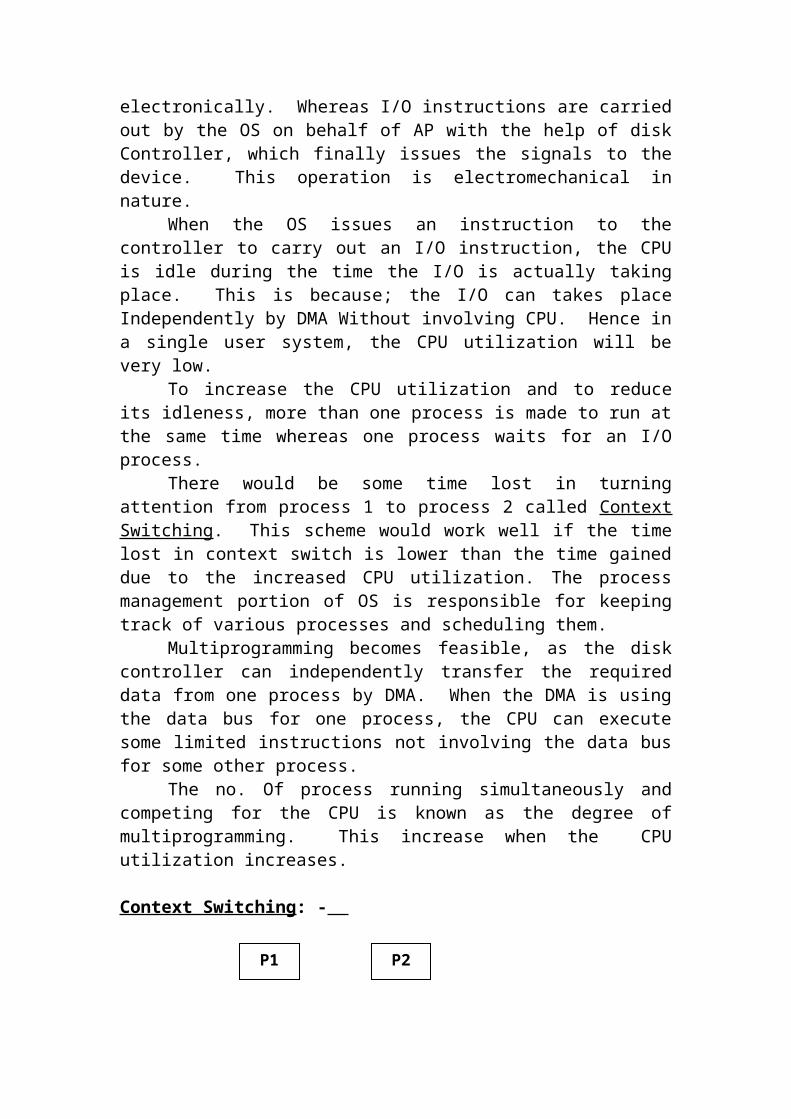
There would be some time lost in turning attention from process 1 to process 2 called Context Switching. This scheme would work well if the time lost in context switch is lower than the time gained due to the increased CPU utilization. The process management portion of OS is responsible for keeping track of various processes and scheduling them.
Multiprogramming becomes feasible, as the disk controller can independently transfer the required data from one process by DMA. When the DMA is using the data bus for one process, the CPU can execute some limited instructions not involving the data bus for some other process.
The no. Of process running simultaneously and competing for the CPU is known as the degree of multiprogramming. This increase when the CPU utilization increases.
Context Switching: -
P1 P2

When the CPU switches from one process to other process, the OS saves the state of the old process and loading the saved state for the new process.
When a process (AP-1) issues an I/O system call, the OS takes over this I/O function on behalf of that process, keeps the (AP-1) away and starts executing another process (AP-2) after storing the context [CPU registers such as PC, IR, SP & other general purpose register] of the AP-1 that can be executed again. But at this time, the CPU may be executing AP-2 and therefore its registers will be showing the values related to AP-2. The context of AP-2 has now to be saved in the register save area and the CPU registers have to be loaded with the saved values from the register save area of the AP-1 to be executed next [for which I/O is complete].
PROCESS STATES: -
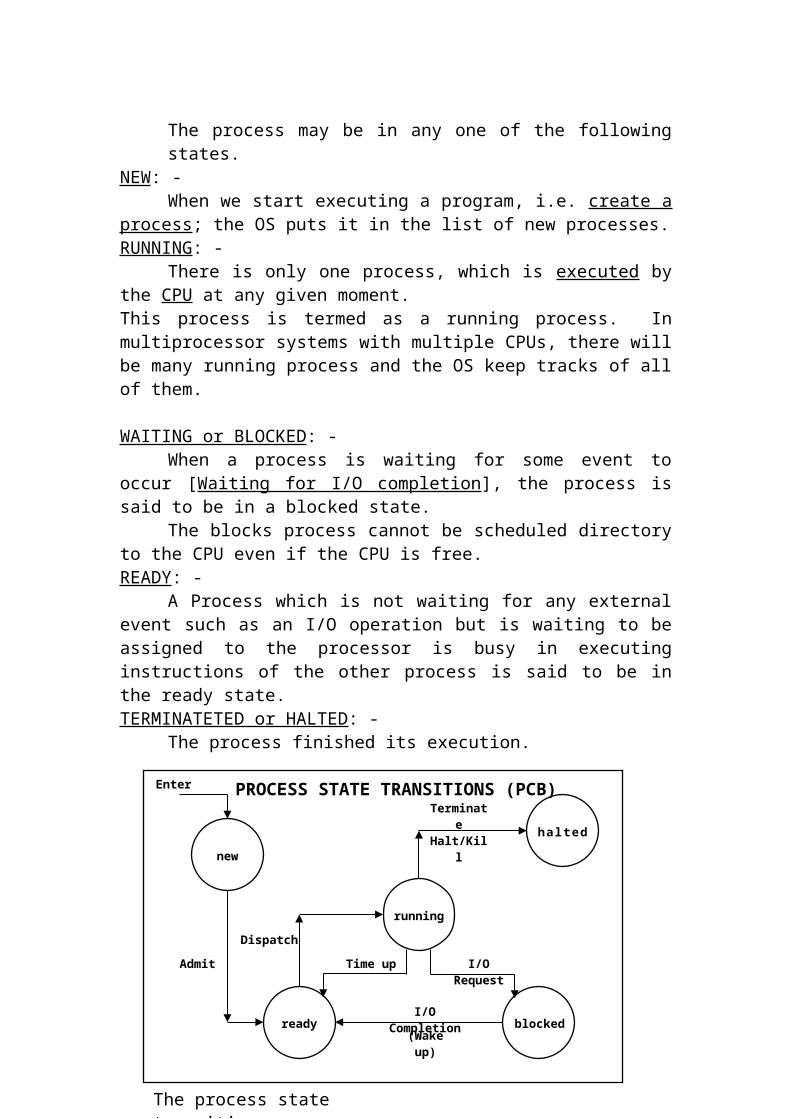
The process may be in any one of the following states.NEW: -
When we start executing a program, i.e. create a process; the OS puts it in the list of new processes.RUNNING: -
There is only one process, which is executed by the CPU at any given moment.This process is termed as a running process. In multiprocessor systems with multiple CPUs, there will be many running process and the OS keep tracks of all of them.
CPU Registers
Register Save Area
Process APC…IR…SP
Process BPC…IR…SP
……
Process A……
Process B……
(i)
(iii)
(ii)
Context switching (from Process A to B)

WAITING or BLOCKED: -When a process is waiting for some event to occur [Waiting for I/O
completion], the process is said to be in a blocked state.The blocks process cannot be scheduled directory to the CPU even if the
CPU is free.READY: -
A Process which is not waiting for any external event such as an I/O operation but is waiting to be assigned to the processor is busy in executing instructions of the other process is said to be in the ready state.TERMINATETED or HALTED: -
The process finished its execution.
PROCESS STATE TRANSITIONS (PCB)
When we start executing a program, i.e. create a process; the OS puts it in the list of new processes. The OS wants only a certain number of processes to be in the ready queue to reduce competition. The OS introduces a process in the new list.
Depending upon the length of the ready queue, upgrades process from new to the ready list. Some systems directly admit a created process to the ready list.
When all the processes, which are previously in the ready lists, are dispatched then this process will be dispatched in tits turn to the running state by loading the CPU register save area.
Each process is given a time slice, to avoid the usage of CPU by indefinitely. When the time slice is over it is put in the ready state again as it is not waiting for any external event.
Enter
Admit
Dispatch
Time up I/O Request
Terminate Halt/Kill
I/O Completion
(Wake up)
new
running
blockedready
hal ted
The process state transition
Within the time slice if the process wants to perform some I/O operation denoted by I/O request, a S/W interrupt results and the OS makes this process blocked and takes up the next ready process for dispatching.
Wakeup operation occurs when the I/O is over for the process, which was in the blocked state. At this time, the h/w generates an interrupt and the changes the blocked state process in to ready state process.
This cycle is repeated until the process is terminated. After termination, it is possible for the OS put this process into the halted state for time being and removes all the details from the memory.
It is a data structure and the OS maintains the information about each process. Each process has a PCB. When the user creates a process, it is created and stored in the memory and it is removed when the process is killed.
Process-id: - OS allocates the no. to each and every process. If there are ‘n’ processes
it allocates 0 to n-1 numbers to each process. Another way is PCB number is given as the process no.
When a process is created, a free PCB slot is selected and its PCB number is chosen as the process-id number, when a process terminates, the PCB is added to a free pool.
Process-state: - It gives the status of the process such as running, ready in the codified
fashion.
Process-id
Process state
Process priority
Register Save AreaFor PC, IR, SP, ……
Pointers to process’s memory
Pointers to other resources
List of open files
Accounting information
Other info if required (current dir)
Pointer to other PCBs
Process Control Block
Process-priority: -It indicates the priority of the process (high or low). It can be externally
by the user (or) set the OS internally.Register Save Area: -
It gives information about accumulator, general-purpose register, PC, SP, IR and status registers. This is needed to save all the CPU register at the context switch.
Pointer to the Process’s memory: -It has the starting address of the process.
Pointers to the other resources: -It gives the pointers to other data structure maintained for that process.
[Address for other routines]List of open files: -
Using this the OS close those files which are opened after finishing the process.Accounting information: -
It gives the information about the usage of resources. Such as connect time, CPU time, and disk I/O time used by the process.Pointers to other PCBs: -
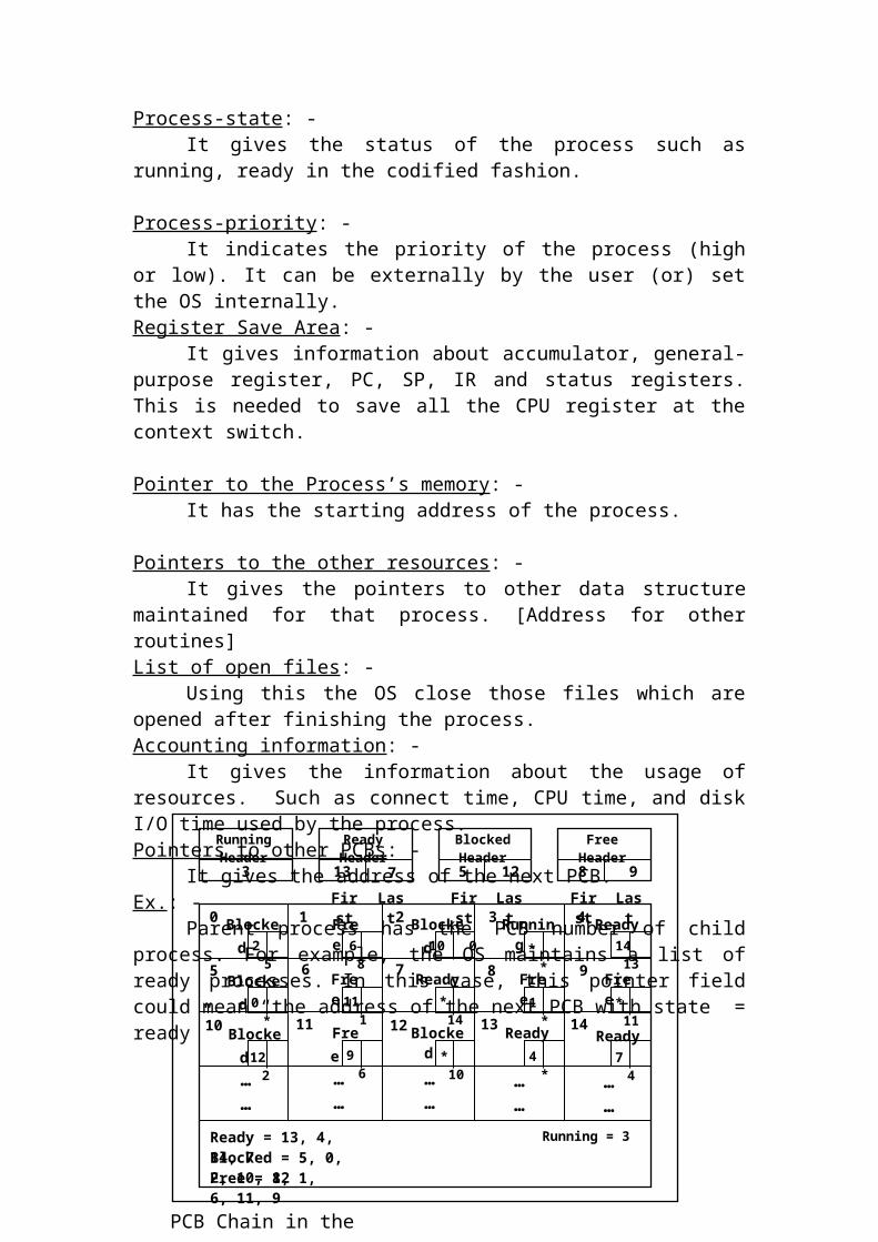
It gives the address of the next PCB.Ex.: -
Parent process has the PCB number of child process. For example, the OS maintains a list of ready processes. In this case, this pointer field could mean “the address of the next PCB with state = ready”
Running Header
Ready Header
Blocked Header
Free Header
0 2 3 4
5 6 7
1
1312 1411
9
10
8
……
……
……
……
……
3 87 12 913 5
Ready = 13, 4, 14, 7
Free = 8, 1, 6, 11, 9Blocked = 5, 0, 2, 10, 12
Running = 3
2 5 * * 14 13
0 *
10 06 8
12 2
11 1 * 14 1 * * 11
* 10 4 * 7 49 6
PCB Chain in the memory
First Last First FirstLast Last
Free
Blocked
Ready
Free
Free
Free
Free
Ready
Ready
Ready
Blocked
Blocked
Running
Blocked
Blocked
The above diagram shows the area reserved by OS for all the PCBs. If an OS allows a maximum of ‘n’ process and the PCB requires x by to of memory each, the OS will have to reserve n x bytes for this purpose. Each box denotes a PCB with the PCB-id or no in the top left corner.
Any PCB will be allocated either to a running process or a ready process or a blocked process. If the PCB is not allocated to any of these three possible states, then it has to be allocated or free. The OS maintains four queues or lists with their corresponding header for each state.
Only one process can be in the run state and hence only one slot will be in the run header. Where as for the other state header it has two slots. The first slot represents the first process in the queue for that state. For (e.g.) In ready header no. 13 represents the process 13, which is first in the ready queue. The second slot represents the PCB no of the last one in the same state.
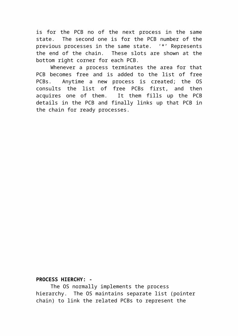
Each PCB itself has two-pointer slot, there are for the forward and backward Chains. The first slot is for the PCB no of the next process in the same state. The second one is for the PCB number of the previous processes in the same state. ‘*’ Represents the end of the chain. These slots are shown at the bottom right corner for each PCB.
Whenever a process terminates the area for that PCB becomes free and is added to the list of free PCBs. Anytime a new process is created; the OS consults the list of free PCBs first, and then acquires one of them. It them fills up the PCB details in the PCB and finally links up that PCB in the chain for ready processes.

PROCESS HIERCHY: - The OS normally implements the process hierarchy. The OS maintains
separate list (pointer chain) to link the related PCBs to represent the process hierarchy. Each PCB will have same additional pointer fields as given below.
(a) Pointer to the PCB of the first child process of this process.(b) Pointer to the PCB of the last child of this process.(c) Pointer to the PCB of the next twin process of the parent.
A
B
C
D
E
GF
H
A Process Hierarchy
Address of first child of this
parent
Address of next child of the same
parent
PCB - B PCB - C
PCB - E
PCB - D
PCB - H
PCB - GPCB - F
PCB - A
PCB chains for process hierarchy
The OS allow a process to have off springs. The new process now created is called a child process. This child process in turn creates further child processes there by creating the process hierarchy.
OPERATIONS ON PROCESS: -
Create a process (p-id) Kill a process Dispatch a process Change the priority of a process Block a process Time up a process Wake up a process
PROCESSS SCHEDULING: -
Scheduling Objectives: -There are many objectives for the OS to schedule various processes.
Some of the objectives conflict with each other and hence the OS designers

have to choose the set of objectives to be achieved before designing an OS. Some of the Objective are-
Fairness Good throughput Good CPU utilization Low turnaround time Low waiting time Good response
Fairness: -It refers to being fair to every user in terms of CPU time that he gets.
(i.e.) All the process (of the users) must be satisfied at the same time by giving the attention of the CPU to all of them by some time slice. But no job will be completed in full.Throughput: -
It refers to the total productive work done by all the users put together. (i.e.) no of processes performed in a unit time.
Fairness and throughput are conflicting objectives.Good CPU utilization: -
It is the fraction of the time that the CPU is busy on the average, executing either the user processes or the OS.
If the time slices in small, the context switches will be more frequent. Hence the CPU will be busy executing the OS instructions more than that of the user processes. Throughput will be low, but the CPU utilization will be very high.
CPU utilization will be low, only if the CPU remains idle.Turnaround time: -
It is the time gap between the times of submission to the CPU to the time of completion.Waiting time: -
It is the time a job spends waiting in the queue after it is being admitted into the ready queue and waiting for the OS to allocate its resources.
Waiting time is included in the turnaround time.Good response time: -
It is the time taken to respond with an answer or result to a question or an event.
It is very useful in time-sharing or real-time systems. Response time is classified into terminal response time and event response time according to the system in which it is applied to.
Response time depends on the degree of multiprogramming, efficiency of hardware and the OS and the policy of OS. Response time is extremely important for on-line or real-time systems.
Concepts of Priority and Time slice: -
As many processes competing for the same available resources like CPU and memory, the concept of priority is very useful. According to the situation, the priority can be global (i.e. external) or it can be local (i.e. internal).
The user specifies external priority, externally at the time of initiating the process. In many systems, the OS allows the user to change the priority externally even during its execution.
If the user does not specify any external priority, then the OS assumesA certain priority called default priority.
Some scheduling algorithms use internal priority.For (e.g.), the OS can set an internal priority as highest for the Shortest
Job First (SJF algorithm). This has two advantages.
1. If short jobs are finished faster, at any time, the no of processes competing for the CPU will decrease. This results in a smaller no of PCBs in the ready or blocked queue. The search times will be smaller thus improving the response time.
2. If smaller processes are finished faster, the no of satisfied users will increase.
The disadvantage is, if a stream of small jobs keeps on coming in, a larger job may suffer from indefinite postponement.
Some OS instead of using the concept of priority uses the concept of time slice. Each process is given a fixed time slice, irrespective of its importance.
The process switch occurs if- A process consumes the full time slice. A process request an I/O before the time slice is over. In this
case, a process switch occurs, because there is no sense in wasting the remaining time slice just waiting for the I/O to complete.
Some OS was a combination of the concepts of priority and time slice to schedule various processes.
Scheduling Philosophies: -There are two kinds of scheduling philosophies. They are,1. Non-preemptive2. Preemptive
A non-preemptive philosophies means that a running process retains the control of the CPU and all allocated resources, until it surrenders control to the OS (on its own). It means that even if the higher priority process enters the system, the running process cannot be forced to give up the control. If the running process
becomes blocked due to any I/O request. Another process can be schedule because the waiting time for the I/O completion is too high.A preemptive philosophy allows a higher priority process to replace a currently running process even if its time slice is not over or it has not request for any I/O. It is suited for on-line, real time processing where interactive user and higher priority processes require immediate attention.
Schedulers: -Scheduler is a program, which selects any one of the processes from a
pool of processes and allocates the CPU for it. It is like a traffic controller.Scheduling Levels: -
Long term scheduling Medium term scheduling Short term scheduling
Long term scheduler: - [Job scheduler]The long-term scheduler selects process from the pool and loads them in
to memory for execution. The long-term scheduler allows only a limited number of processes in the ready queue, which can be accommodated in it to compete for the CPU. If the no of ready processes in the ready queue becomes very high, it is difficult for the OS to maintain long lists and context switching and dispatching becomes complex. Hence it limits the no of processes to enter into the ready queue.Short term scheduler: - [CPU scheduler]
It decides which of the ready processes is to be scheduled or dispatched next from the ready queue to compete for the CPU.Medium term scheduler: -
If a particular process (AP-1) is in its blocked state and another process (AP-2) is next to this process (AP-1) in blocked state, even after a time slice if I/O is not completed for AP-1 and completed for AP-2, then AP-1 prevents AP-2 to get into the ready state. Hence AP-1 is removed from the PCB chain (memory) and it is moved to swap out blocked state. I f the I/O is completed in that state then it will be moved into swapped out but ready state and then only enters into the ready queue.When some memory gets freed, the OS looks at the list of swapped but ready process and decides which one is to be swapped in and after swapping it in, links that to the PCB chain of ready processes for dispatching. Medium term scheduler does it.CPU scheduling: -
CPU scheduling is a basic concept in multi programming. It deals with the problem of deciding which of the processes in the ready queue is to be allocated to the CPU. In a multiprogramming environment all the programs available in memory. At one time the CPU is allocated to only one job and the remaining jobs are placed in a queue. If the process, which is in CPU, waits for I/O completion, the OS takes the CPU away from that process and gives the CPU to another process, which is in ready queue. The short-term scheduler

carries out the selection process in the ready queue. A ready queue may be implemented as a FIFO queue, priority queue, a here (or) an unordered link list.
Dispatcher: -It is a module, which gives the control of the CPU to the process
selected by the CPU scheduler. The function of dispatcher-(a) Switching context(b) Switching H/W to user & system mode.(c) Jumping to the proper location in the user program to restart that
program.The time taken by the dispatcher to stop one process and start another running is called dispatch latency.
Scheduling Algorithms: -
(i) FCFS(ii) Shortest Job First(iii) Priority scheduling(iv) Round-robin scheduling(v) Multilevel queue scheduling(vi) Multilevel feedback queue scheduling
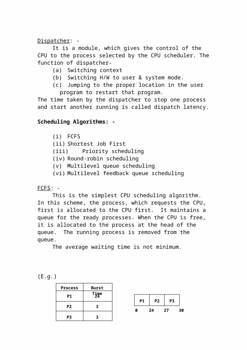
FCFS: -This is the simplest CPU scheduling algorithm. In this scheme, the
process, which requests the CPU, first is allocated to the CPU first. It maintains a queue for the ready processes. When the CPU is free, it is allocated to the process at the head of the queue. The running process is removed from the queue.
The average waiting time is not minimum.
(E.g.)
Average waiting time = 0 + 24 + 27 + 30 = 51/3 = 17FCFS is non-preemptive (i.e.) once the CPU is allotted to the process; it releases the CPU either by terminating (or) by requesting I/O.
Shortest Job First: -
Process Burst Time
24
3
3P3
P2
P1P1 P2 P3
0 24 27 30
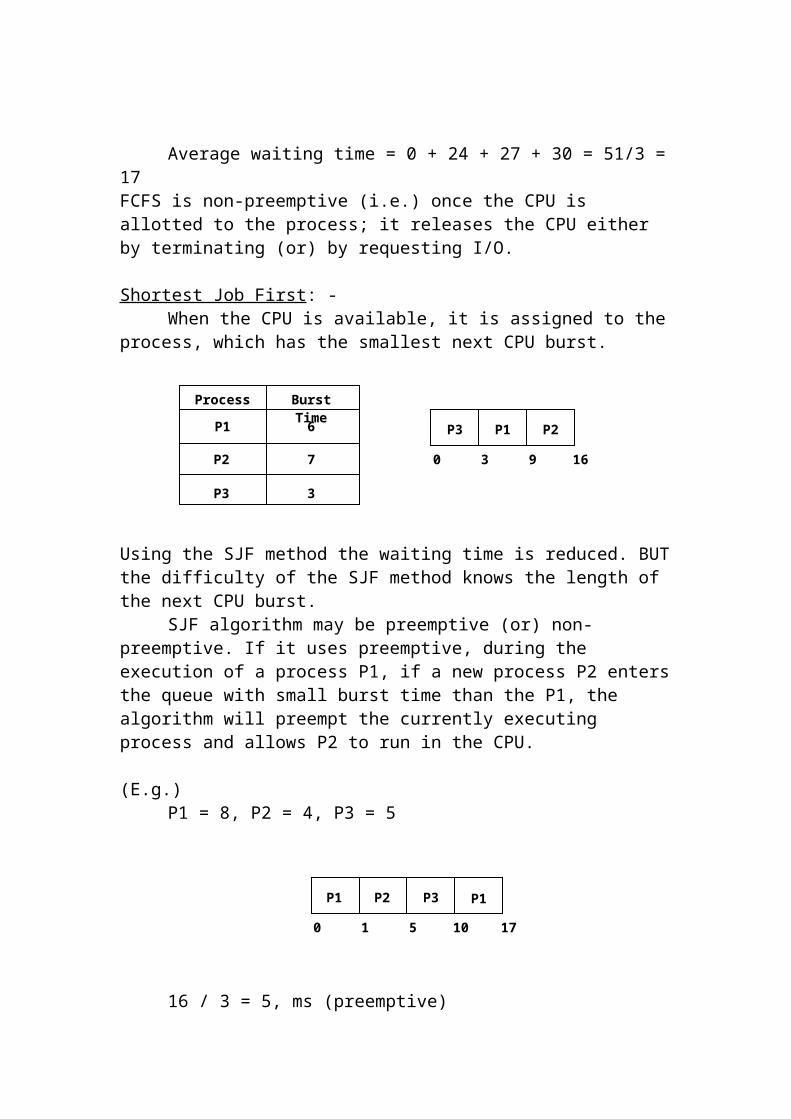
When the CPU is available, it is assigned to the process, which has the smallest next CPU burst.
Using the SJF method the waiting time is reduced. BUT the difficulty of the SJF method knows the length of the next CPU burst.
SJF algorithm may be preemptive (or) non-preemptive. If it uses preemptive, during the execution of a process P1, if a new process P2 enters the queue with small burst time than the P1, the algorithm will preempt the currently executing process and allows P2 to run in the CPU.
(E.g.)P1 = 8, P2 = 4, P3 = 5
16 / 3 = 5, ms (preemptive)20 / 3 = 6, ms (non-preemptive)
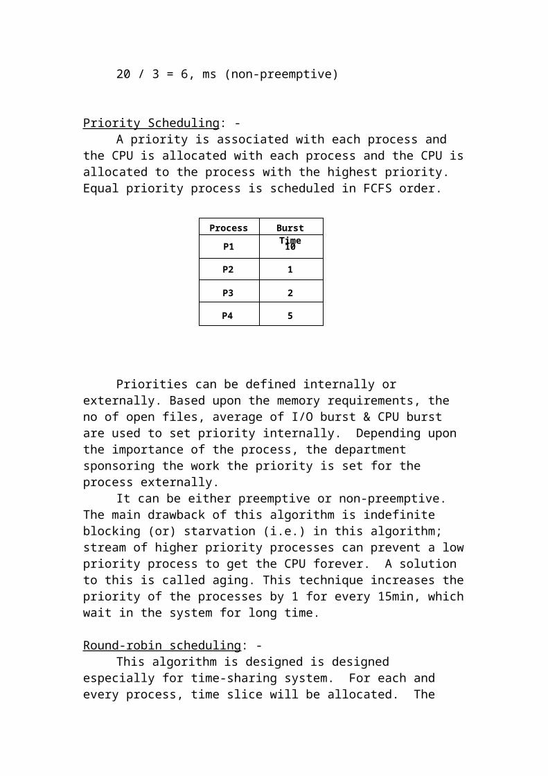
Priority Scheduling: -A priority is associated with each process and the CPU is allocated with
each process and the CPU is allocated to the process with the highest priority. Equal priority process is scheduled in FCFS order.
Process Burst Time
6
7
3P3
P2
P1 P3 P1 P2
0 3 9 16
P1 P2 P3
0 1 5 10
P1
17
Process Burst Time
10
1
2P3
P2
P1
P4 5
Priorities can be defined internally or externally. Based upon the memory requirements, the no of open files, average of I/O burst & CPU burst are used to set priority internally. Depending upon the importance of the process, the department sponsoring the work the priority is set for the process externally.
It can be either preemptive or non-preemptive. The main drawback of this algorithm is indefinite blocking (or) starvation (i.e.) in this algorithm; stream of higher priority processes can prevent a low priority process to get the CPU forever. A solution to this is called aging. This technique increases the priority of the processes by 1 for every 15min, which wait in the system for long time.
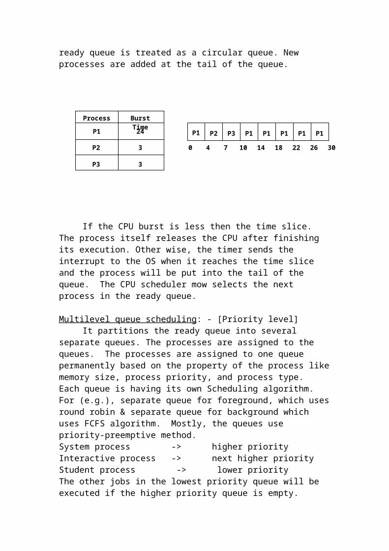
Round-robin scheduling: -This algorithm is designed is designed especially for time-sharing
system. For each and every process, time slice will be allocated. The ready queue is treated as a circular queue. New processes are added at the tail of the queue.
If the CPU burst is less then the time slice. The process itself releases the CPU after finishing its execution. Other wise, the timer sends the interrupt to the OS when it reaches the time slice and the process will be put into the tail of the queue. The CPU scheduler mow selects the next process in the ready queue.
Multilevel queue scheduling: - [Priority level]It partitions the ready queue into several separate queues. The processes
are assigned to the queues. The processes are assigned to one queue permanently based on the property of the process like memory size, process priority, and process type. Each queue is having its own Scheduling algorithm. For (e.g.), separate queue for foreground, which uses round robin & separate queue for background which uses FCFS algorithm. Mostly, the queues use priority-preemptive method.System process -> higher priorityInteractive process -> next higher priority
Process Burst Time
24
3
3P3
P2
P1 P1 P2 P3 P1 P1 P1 P1 P1
0 4 147 10 18 22 26 30
Student process -> lower priorityThe other jobs in the lowest priority queue will be executed if the higher priority queue is empty.
Process is permanently assigned to a queue. They do not move between queues.
Multilevel feedback queue (or) heuristic scheduling: -It allows a process to move between queues. Based on the different CPU
burst time, processes may be put into different queues. A process with high CPU burst time will be moved to a lower priority queue. Similarly, a process that waits for a long time may be to a higher priority queue & prevents starvation. When the lower-priority queues are empty, the higher priority queue will be executed.
When the process in Q1 reaches the 8ms, it is preempted and moved in to Q1. When Q0 is empty, it takes the process in Q1 & when it reaches 16ms, it is preempted and moved into Q2. When Q1 is empty, Q2 will be executed.
This Queue is defined by the following parameter.
1. No of queue.2. Scheduling algorithm for each queue.3. The method to determine when to denote process to a higher-priority
queue.4. The method to determine when to denote a process to a lower-
priority.5. The method to determine in which queue the process will enter,
when it needs service.Multiple processor scheduling: -
(E.g.)3-reservation counter (Railways)
Time slice = 8 ms
Time slice = 16 ms
Time slice = 32 ms
Q0
Q1
Q2

When the processors are identical (homogenous), any available processor Can be used to run any process in the queue. When the processors are heterogeneous (different) the programs, which uses from the set of a particular processor.
In a homogeneous multiprocessor, some limitations are there on scheduling. (i.e.) If a I/O device of a particular system is connected to the processor through bus & the process wants to use that device must be scheduled to run on that processor. All the processes into a single queue and scheduled onto any available processor. Each processor examines the queue & selects a process to execute. But 2 processors do not choose the same process, for this, one processor is appointed as a scheduler for other processors, which is a master-slave structure.
Multi-tasking: -A process is divided into several tasks and each task will be executed
concurrently in the same way that a multi-user OS supports multiple processes at the same time.(E.g.)
Program without multitasking
Begin While NOT EOF do
Read a recordProcess a recordWrite a record
End while End.From the above example, 3 tasks are there to read from the disk, process
that and write it into the disk. Their 3 tasks are executing in sequence (one by one) with out multitasking concept. But the same program can be written using multitasking concept as follows.
Begin While not EOF do
BeginTask-0-begin
Task-0-end Task-1-begin
Task-1-endEnd;
End while
Read a recordProcess a record
Task 0
Write a Task 1

End
So, task1 is executed concurrently while I/O for task 0 is going on,1. When the process starts executing, the OS creates PCB, in addition
with that it also create TCB [Task Control Block].2. OS maintains a queue for tasks also [ready queue] like for process. A
task can get blocked like a process and hence a TCB needs to have a register save area for each task within a process.
3. The tasks also have priorities and states. It may be in a ready, blocked (or) running state and all the TCBs are linked together like PCBs, regarding with their states.
4. The OS selects the higher priority ready task within that process and schedules it.
5. If the process time slice is not over but current task is either over or blocked, the OS chooses the next higher priority ready task within that process and schedules it. But if there is no task in the ready task queue, it means that either all the tasks are over or all the remaining tasks are in blocked state. If all the tasks are in blocked state, the process is also in blocked state.
Multi-threading: -It is similarly to multitasking. Some of the OS uses concept of multi-
threading. Each thread has a stack, PC and register save area (as in TCBs), but it shares the same address space with others. Different threads read and write the same memory locations and hence inter thread communication can be achieved easily.
Some of the Os has another concept session. Each session consists of multiple processes and each process consists of multiple thread like a child process to a parent process.
The idea of providing multiple sessions is to simulate multi window environment. Each session has its own virtual terminal with a keyboard, mouse and screen.
If each session have some screen I/O instructions then actual physical screen and the output of that session, which is running in the foreground is allocated the physical video RAM, where as the other sessions are allocated the virtual memory (systems memory).
If any one of the session, which is running in the background, is brought as the foreground session then the physical video Ram and other physical memory is allocated to that foreground session.
Arrangement of logical records: -
The applications program is responsible for creating these records. The length of each record may be in some bytes [for example record length is 700

bytes]. These records may or may not be in any specific sequence. The OS assigns a Relative Record Number (RRN) to each record, starting with 0.
In the above diagram, all the records are in sequence. [(i.e.) put one after other] But this is a logical view of the file by the application programmer. But the OS may scatter the records in variety of ways, hiding these details from the programmer, and each time OS provides the address translation facilities.
Relative Byte Number (RBN): -This is the staring byte number for a given record.
RBN = RRN * RL where, RL is Record Length
For example, if RL = 700 bytes, and RRN = 10 then
RBN = 10 * 700 = 7000
Relationship ship between RRN & RBN
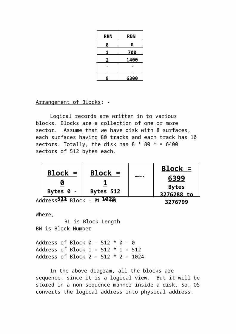
Arrangement of Blocks: -
Logical records are written in to various blocks. Blocks are a collection of one or more sector. Assume that we have disk with 8 surfaces, each surfaces having 80 tracks and each track has 10 sectors. Totally, the disk has 8 * 80 * = 6400 sectors of 512 bytes each.
RRN = 0Bytes 0 -
699
RRN = 0Bytes 699 -
1399
…….
RRN = 0Bytes 6300 -
6999
RRN RBN
0 0
.
.
9 6300
2 14007001
.
.
Block = 0Bytes 0 - 511
Block = 1Bytes 512 -
1023
…….
Block = 6399
Bytes 3276288 to 3276799

Address of Block = BL * BN
Where,BL is Block Length
BN is Block Number
Address of Block 0 = 512 * 0 = 0Address of Block 1 = 512 * 1 = 512Address of Block 2 = 512 * 2 = 1024
In the above diagram, all the blocks are sequence, since it is a logical view. But it will be stored in a non-sequence manner inside a disk. So, OS converts the logical address into physical address.
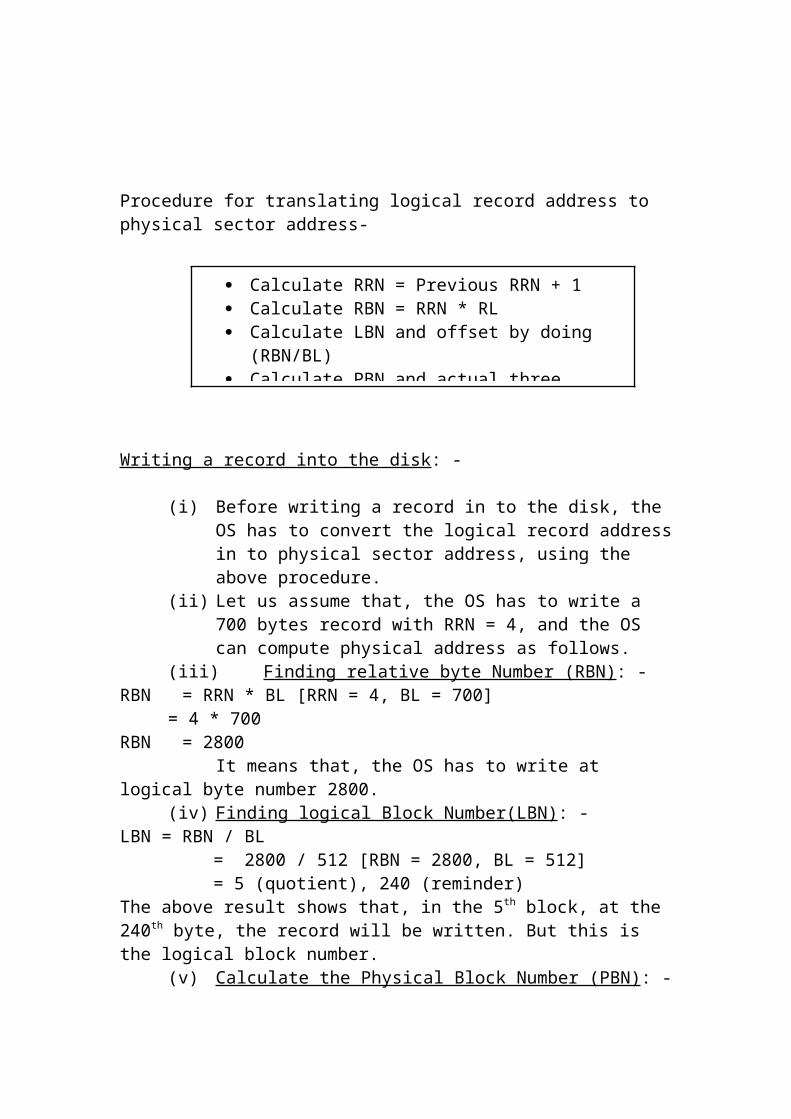
Procedure for translating logical record address to physical sector address-
Writing a record into the disk: -
(i) Before writing a record in to the disk, the OS has to convert the logical record address in to physical sector address, using the above procedure.
(ii) Let us assume that, the OS has to write a 700 bytes record with RRN = 4, and the OS can compute physical address as follows.
(iii) Finding relative byte Number (RBN) : -RBN = RRN * BL [RRN = 4, BL = 700]
= 4 * 700 RBN = 2800
It means that, the OS has to write at logical byte number 2800.(iv) Finding logical Block Number(LBN) : -
LBN = RBN / BL = 2800 / 512 [RBN = 2800, BL = 512] = 5 (quotient), 240 (reminder)
Calculate RRN = Previous RRN + 1 Calculate RBN = RRN * RL Calculate LBN and offset by doing (RBN/BL) Calculate PBN and actual three dimensional
addresses

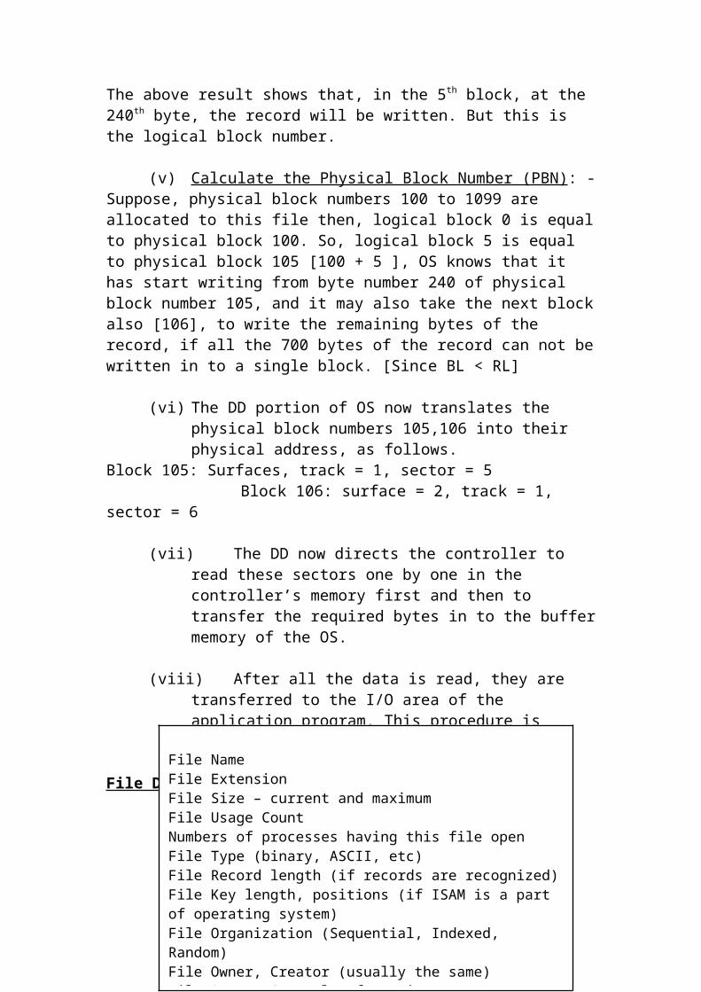
The above result shows that, in the 5th block, at the 240th byte, the record will be written. But this is the logical block number.
(v) Calculate the Physical Block Number (PBN) : -Suppose, physical block numbers 100 to 1099 are allocated to this file then, logical block 0 is equal to physical block 100. So, logical block 5 is equal to physical block 105 [100 + 5 ], OS knows that it has start writing from byte number 240 of physical block number 105, and it may also take the next block also [106], to write the remaining bytes of the record, if all the 700 bytes of the record can not be written in to a single block. [Since BL < RL ]
(vi) The DD portion of OS now translates the physical block numbers 105,106 into their physical address, as follows.
Block 105: Surfaces, track = 1, sector = 5 Block 106: surface = 2, track = 1, sector = 6
(vii) Now the specified records are written into the physical sector address.
Reading a record in to the disk: -
(i) Before reading a record, the OS converts the logical address in to physical address.
(ii) Let us assume that, the OS has to write a 700 bytes record with RRN = 4, and the OS can compute physical address as follows.
(iii) Finding relative byte Number (RBN) : -RBN = RRN * BL [RRN = 4, BL = 700]
= 4 * 700 RBN = 2800
It means that, the OS has to write at logical byte number 2800.
(iv) Finding logical Block Number(LBN) : -LBN = RBN / BL = 2800 / 512 [RBN = 2800, BL = 512] = 5 (quotient), 240 (reminder)The above result shows that, in the 5th block, at the 240th byte, the record will be written. But this is the logical block number.
(v) Calculate the Physical Block Number (PBN) : -Suppose, physical block numbers 100 to 1099 are allocated to this file then, logical block 0 is equal to physical block 100. So, logical block 5 is equal to physical block 105 [100 + 5 ], OS knows that it has start writing from byte number 240 of physical block number 105, and it may also take the next block also [106], to write the remaining bytes of the record, if all the 700 bytes of the record can not be written in to a single block. [Since BL < RL]

(vi) The DD portion of OS now translates the physical block numbers 105,106 into their physical address, as follows.
Block 105: Surfaces, track = 1, sector = 5 Block 106: surface = 2, track = 1, sector = 6
(vii) The DD now directs the controller to read these sectors one by one in the controller’s memory first and then to transfer the required bytes in to the buffer memory of the OS.
(viii) After all the data is read, they are transferred to the I/O area of the application program. This procedure is repeated for all the records in a file.
File Directory Entry: - [FD Entry]
Use Of FD during Open/ Close Operation: -When the application program wants to open a file, the OS invokes the
appropriate system call. The system call for “open” first searches the file directory in the hard disk, by using the directory name. The hard disk contains list of FD for various files, which is called Active File List (AFL).
The list is arranged in some order [Index on AFL using file name]. Now the Os checks the access control information of the user can proceed his operation.
During accessing the file, the information such as the size, date, etc will be changed in to the FD entry by the OS. When the file is closed, the updated directory entry is written back to the hard disk.
Disk Space allocation Methods: -
File Name File ExtensionFile Size – current and maximum File Usage CountNumbers of processes having this file openFile Type (binary, ASCII, etc)File Record length (if records are recognized)File Key length, positions (if ISAM is a part of operating system)File Organization (Sequential, Indexed, Random)File Owner, Creator (usually the same)File Access Control InformationFile Dates (Creates, last Usage etc.)Other informationFile Address (Block Number) of the first block

While allocating the Disk space to the files, the OS uses 2 basic major methods. They are,
(i) Contiguous allocation(ii) Non-contiguous allocation
Contiguous allocation: -In this method, continuous blocks are allocated to the files. In this scheme during the creation of the file, the user should estimate the maximum file size including the future expansion and then requests the OS to allocate the memory space through a command.
Demerits of contiguous allocation: -
Space Wastage: -Until the file reaches maximum size, any bocks are free and cannot be
allocated to any other file, thus wasting a lot of disk spaces.
Inflexibility: -If the file grows more than the maximum size of the file [(i.e.) we want
to add more records], the file needs some more blocks. So, if we want to add few blocks without disturbing contiguity, the will be loaded in to a floppy, delete that file, and request the OS to allocate new contiguous space with the new file size. Then the file from floppy will be loaded back to the new allocated space. Thus this method leads to inflexibility. Even though it has lot of disadvantages, some uses this method due to easy implementation.
Advantage: -Contiguous allocation method is useful when the OS uses buffered I/O
method. In buffered I/O method, OS reads a number of consecutive bocks at a time, thus it reduces the head movement and increases the I/O speed.
Contiguous allocation method uses two methods.1. Block Allocation List Method2. Bit Map method
Block Allocation List: -OS maintains 2 tables to have the details about blocks allocated to the
files and free blocks.
Block NumberFile
From To
0 ABC
TotalNumber
CUST
EMP49 100 52
204021
54
File Allocation table
From To Total Number
5
281
101 200
350
48
70
100
841
20 16
… ……
Free Block List
Using the above tables the OS allocates blocks to the file by any one of the following 3 methods.
(i) First fit(ii) Best fit(iii) Worst fit(iv) Chained method
FIRST FIT: -In this method, the OS checks the free block list entries and allocates
from the first entry, if it is equal or greater than the required number of blocks. For example, consider the free block list as follows and the file needs 6 blocks.
In this free list, in the first entry it has 16 free blocks which is greater than 6 so it is allotted to the file.BEST FIT: -
In this method, the OS will choose the entry which is smallest among all entries bit equal or bigger than the required amount of block so this free list should be sorted out in this method.
Suppose we need 2 blocks, it will choose the 3rd entry. After taking 2 blocks from it, it will add 5 blocks to the free list.Disadvantage: -
Every time, the free list has to be sorted.Advantage: -
From To Total Number
40
100
70 90
110
68
10
20
860
56 16
… ……
Free Block List
To t a l B l o c k L i s t
8
20
16
10
Free Block List
It reduces the wastage due to fragmentation.WORST FIT: -
In this method, the OS searches the entire free list, and it selects the largest entry. Suppose, the largest block is 1000 among all the free blocks, OS will select this entry. But if our requirement is 50 blocks, remaining 950 blocks are added with the free list, and for the further allocation if 950 is the largest entry, it is used. At last, it will have some free space, which can’t be allocated to the files, so it can be collapsed with the other free holes [coalescing].
Example for coalescing: -
From the above entry, it has free space from 40-49 and 100-200. In between, it has “customer” file. If we delete this file, it has sequence of free blocks with 3 different entries like, 40-49, 50-100, and 101-200. So, by coalescing method, these 3 entries are made as a single entry, and it has a chunk (bulk) of free space.
So, OS will resort the new free blocks and the new list can be use later for best or worst fit algorithm.CHAINED ALLOCATION: -
The OS reserves various slots to maintain the information about free blocks. Each slot contains 5 fields.
1. Slot number2. Allocated (A)/Free status code (F)3. Starting block number of the free list4. Number of blocks5. Next slot of the same status
0 A 0 5 2 1 F 5 16 3 3 A 21 20 4 3 F 41 8 54 A 49 52 6 5 F 101 100 7 6 A 201 80 * 7 F 281 70 *8 9 10 11
CDE FREE CUSTOMER FREE EMP
21 40 49 100 200
CDE FREE EMP
21 40 200
0 6
Allocated List Header Free List Header
71
FREE FREEFREEFREE
The above diagram is having 11 slots, and 8 (0-7) slots are used, 8-11 slots are free. End of the chain is indicated by ‘*’ 2 list headers are maintained to go through the allocated list and free list. In this method, there is no need for the OS to maintain 2 seperate tables (free list, file allocation). During the creation / deletion of a file, OS should change the 2nd and 5th slot entry.When it allocates the free slot for a file and if it further contains the free slot, which should be made as a seperate entry at the end of the free slot. For example, if the free slot contains 5 blocks, but 3 blocks are needed, the remaining 2 blocks are made as a seperate entry.BIT MAP METHOD: -A bit map is another methods of keeping track of free/allocated blocks. A bit map maintains one bit for every block. Bit 0 indicates the free block and bit 1 indicates the allocated block. During the creation of a file, is the file needs 7 blocks, using the first fit method, OS searches the consecutive 7 0’s and allocate it for files and change it to 1.When a file is deleted, the file directory entry is consulted and the corresponding blocks are freed. So, the corresponding bits, which are 1 in the bit map, are set to 0. It is used only to manage the free blocks and so, it need not show the file to which a specific block is allocated.
Advantage: -It is very easy to implement.
Disadvantage: -It is very expensive.
NON-CONTIGUOUS ALLOCATION METHOD: -In Non-contiguous allocation method, the OS will allocate the blocks to
the files in a non-sequence manner. In this method, the maximum size of the file does not have to be predicted at the beginning.Advantage: -
1. The file can grow as per the needs of the user. This method reduces the wastage of disk space.
2. If the file gets full during the execution of a program, the OS automatically allocates additional blocks, without aborting the program and without asking for the operator’s intervention.
Disadvantage: -The routines are complex methods of implementing non-contiguous.1. Chained allocation2. Indexed allocation
Chained allocation: -Non-contiguous method also user chained allocation like contiguous
method. But this chained allocation method is different from the contiguous chained allocation method.
1 1 1 1 01 0 0 0 0 0 0 11111
In non-contiguous method, all the blocks are not in a sequence manner. So, the OS must have a method of traversing to the next block, so that all the blocks in a file are accessible, and the whole file can be read in sequence. For that, it uses the pointer variable, which gives the address of the next block, in the same file.
FILE = “CUST”ALLOCATED BLOCKS (4, 14, 6, 24, 20)
a) File directory entry gives the first block number allocated to the file. For instance, the above figure shows that the first block for file “CUST” is 4.
b) A fixed number of bytes in each block are used to store the block number of the next block allocated to the same file. It means that, if 512 bytes are allotted for a block, only 510 bytes can be used to store the data and 2 bytes are used for a pointer.
c) Some predefined special characters are used as pointers (‘*’ in the above example) in the last block of a file to indicate the end of the chain.
Indexed method: -In chained method, the address of the next block is maintained in a
block itself. But in indexed method these pointers are formed as a seperate list. So, an index can be viewed as an externalized list of pointers.
The above diagram is an index, which contains all pointers of all blocks. But to maintain this index itself, separate block should be allocated.
0
11
1 2 3 4
10
5
16
29
23
17
21
15
9
28
2218
12
6
272524 26
20
14
87
13
19
(14)
(6)
(24)
(20)
(*)
5 7 3 6 10

USER’S VIEW OF DIRECTORY STRUCTURE: -
Directory is a file of files. Several OS allows file hierarchy structure called inverted tree hierarchy. (i.e.) Root is at the top and branches may be the file or the sub directories. To handle the user’s directory, OS maintains a profile file, which has several profile records. Each profile record gives the information about the user name, password, and their home directory. When the user logs onto the system, the OS opens a profile file and selects the profile record for them and checks the password. If it is correct, it opens the home directory for that user. The system administrator gives the home directory for the user when he creates login for them.
Ex.: -
The above diagram shows the hierarchical file structure. Directories are drawn as rectangles and all the files are drawn as circles. The OS allows the user to start from the top (i.e.) the root directory and traverse down to any directory or any file.
Complete path: -To reach any other directory or file from any current directory, we
should give the complete path name. For example to print the BUDGET file under the directory production, the command is, PRINT / PRODUCTION / BUDGET.
Costing
Production
Costing
PurchaseWork Order
Budget
Vendor
Budget
Partial path name (or) Relative path: -For the large hierarchies, the specification of the complete path is
difficult. So many systems allow the user to specify partial path name (or) relative path name. For example assume that the user is currently in the directory /PRODUCTION. The user can now give PRINT BUDGET instead of giving the complete path. The absence of slash (/) in the path name tells the Os that the path is partial with respect to the current directory.
Merits of Hierarchical File System: -
Facility to have unique file name: -If there is no hierarchy, and all the files for all the users are put together under same directory, then duplicate file names will exist. Then the OS has to check against a list of already existing files.So, it is convenient to have seperate directories for different users or applications. In this case, the same file name can be used a number of times in a whole system, but it does not appear more than once under one directory.
Easy sharing: -With the hierarchical file system, sharing of files or directories is possible, and thus preventing the need for copying the entire file or directory. This saves disk space. For example, if one directory has 2 different paths (i.e.) / prod/purchase (or) \sales \ purchase, there is only one copy of purchasing directory will be maintained by the OS to avoid duplication,The hierarchical file system also allows aliases (i.e.) the same file by 2 names. For sharing, the file or dir has to previously exist less than one directory, and that we can create link from another dir.
Better Protection: -To provide better protection, OS gives various protection (or) access control facilities to the files. For instance, a specific file should be readable only for users A and B, whereas only user B can be allowed to update it. This access control information is a part of the directory entry and is checked before the OS allows the user to use the file.
DEVICE DRIVER: - (DD)
It is software, which resides (stored) in the hardware called device controller. Each device in the computer is having controllers to control it. These controllers are connected with the devices, CPU, and memory through buses and interfaces.

The interface, which connects device and the controller, may be serial or parallel. The interface has the hardware to convert the parallel data into serial data and vice versa.
DATA TRASMISSION BETWEEN DEVIES THROUGH INTERFACE: -
From this diagram, the interface connects the keyboard and bus serially. The interface connects the CPU through bus parallely. From the keyboard the data is transmitted to the CPU through interface.
Path management of the device controller: -Functions of device controller can control multiple devices. At any time, a controller can control only one device and so the other devices which requests the controller will put into the queue called device request queue (DRQ). So, it will take more time for response to the device.
Functions of device controller: -Functions of device controller can be divided into 2 units.
(i) Channel(ii) Control unit
Channel: -It is a path (or) a bus that can execute same specific I/O instruction.
DMADisk
CPUInterface BUS
Device, Controller and CPU
CPUBUSControllerKeyboard
Keyboard data transmission
Control unit: -It connects the channels to the devices. A controller normally controls devices of the same type. For example, a printer controller can control only the printers and not the other devices like keyboards.But in contrast, the channel can be connected to the controllers of different type. For example, a channel can connect keyboard controller, printer controller etc.,One channel can be connected to many controllers. Similarly, one controller can be connected to many devices.
The paths which connects these channels and controllers may be symmetric (or) asymmetric.Symmetric path: -In symmetric arrangement, any device can be reached through any controller and any channel.
Channel 0
Drum Control
Unit
Disk Control
Unit
Main Memory
Drum 0
Drum 1
Drum 2
Disk 0
Disk 1
Channel, Controller, Devices
Memory
Channel0
Control Unit 0
ControlUnit 1
Channel1
Symmetrical
Device 1
Device 0

Asymmetric path: -In asymmetric arrangement, any path doesn’t lead to the device through any controller and channel but the pre-assigned path leads to the device.In this arrangement, due to the multiple paths,
(1) Response time increases.(2) Speed will be reduced(3) Complex routines are needed for DD
Sub modules of device driver: -
1. I/O Procedure2. I/O Scheduler3. Device handler4. ISR
I/O Procedure: -It converts the logical block numbers into physical address and manages
the paths between all the devices, controllers, and channels.I/O Scheduler: -
Channel 0
Drum Control
Unit
Disk Control
Unit
Main Memory
Drum 0
Drum 1
Drum 2
Disk 0
Disk 1
Asymmetrical Path Management
It takes the jobs from the queue based upon its priority and allocates the device for that.Device handler: -
It communicates with the I/O devices and executes the I/O instruction.ISR: - (Interrupt Service Routine)
It is a routine to handle the interrupt.
Data structure used in I/O procedure: -1. Channel control block [CCB]2. Control unit control block [CUCB]3. Device control block [DCB]4. I/O request block
Channel control block [CCB]: -This data structure maintains the details about the following things:
a) Channel statusb) List of control units connected to this channelc) List of processes waiting for this channeld) Current process using this channel
Control unit control block [CUCB]: -The details stored in this data structure are,
a) Control unit IDb) Control unit statusc) List of devices connected to this CUd) List of channels connected to this CUe) Current process using this CU
Device control block [DCB]: -a) Device IDb) Device statusc) Device characteristicsd) Device descriptore) List of control units connected to this devicef) List of processes waiting for this CU g) Current process using this device.
IORB: - (Input / Output request block)a) Origination processb) Amount of data to be transferredc) Mode(R/W)d) Destination addresse) Source address.
I/O Scheduler: -I/O Scheduler is a program, which selects the job among several jobs
and allocates the job to the desired I/O devices. This I/O scheduler is different
from CPU scheduler. I/O scheduler allocates I/O devices to the process whereas CPU to the process.
All the IORBS for all the jobs, which are in queue, are connected to DCB. I/O scheduler picks up an IORB from the chain according to the scheduling policy, and it requests the device handler to actually carry out the I/O operation, and then Deletes that IORB from the queue. The status of the CCB, CCUB and DCB are updated. I/O procedure prepares the IORB and submits it to the I/O scheduler then I/O scheduler chains it to the DCB.
DIFFERENT POLICIES OF I/O SCHEDULING: - (OR) I/O SCHEDULING ALGORITHMS: -
(i) First come first served (FCFS)(ii) Shortest Seek Time First (SSTF)(iii) SCAN(iv) N-step SCAN(v) Circular (C) SCAN
FCFS: -
Pending Request Queue
header
Device Info ID. Status
Characteristics
Other Info
Current Process
List of CUs connected
….….
Process Id Amount.. Mode.. Addresses
Device Control Block (DCB)
.
.
First IORB for the device to be scheduled
Next IORB for the device
Last IORB for the device
Device Control Block with IORBs

In FCFS the process which makes the request first is served first. But this method is not suitable for reducing the head movement. All the IORBS are connected to DCB’S in FIFO sequence, as in the above diagram. After one IORB is dispatched, that IORB is deleted and the DCB now points to the next IORB of the same device. When one new IORB is arrived, it is added at the end of the chain. To maintain this, DCB contains the field, which has the address of last IORB. Each IORB is having the address of the next IORB and previous IORB.From the above diagram, at first the read/write head is positioned in between the tracks 2 and 3. The order of arriving jobs is 0, 1, 2, and 3. So the head is moved to the track 0 first and then to track 1, next to track 2 and at last to track 3. So, the movement of head movement is more.
SHORTEST SEEK TIME FIRST (SSTF): -It chooses the IORB, which requires the shortest seek time with respect
to the current head position.
Advantage: -It improves the throughput.
Disadvantage: -It can delay a request for a long time.
1 2 03
FCFS method
12 0 3
SSTF method
From this diagram, IORB0 is chosen first, and OS has 2 choices of picking either IORB1 or IORB3 next. It IORB3 is selected then the head movement for IORB1 and IORB2 will be increased. Instead of selecting IORB3, if IORB1 is selected, then IORB2, which requires shortest seek time can be completed and the IORB3 will be carried out.
Every time, the disk arm position changes or an IORB is added or deleted from the DCB chain. I/O schedule will have to calculate the seek time for each IORB, with respect to the current head position.
SCAN METHOD: -In this method, the R/W head starts a scan in some direction, it picks up
all the requests in that direction and then reverses the direction. When the scan in one direction is going on and if the new request comes in the opposite direction, then the IORB for this request will be added in the chain, but will not be serviced. Only the pending IORBs in the chosen direction is serviced first. The only new IORB request will be serviced. If the new arrival is in the direction of the SCAN, it will be serviced during the scan itself. The IORBs are chained in ascending or descending order of the track number.
04 3 2 1
SCAN method

N-STEP SCAN METHOD: -This method allows the addition of new IORBs in the chain only at the
end of scan before reversing the direction of the traversal of R/W arms. So. While the scan is going on in one direction, new additions are kept separately and not added to the chain. They are all added when the direction is reversed, based on the seek steps required for each IORB.
At first, the tracks 0, 1, 2 are serviced. During the service of track 1, new arrival for tracks 3 and 5 occurs. But they won’t be serviced. After servicing track 1, it provides service to the already existing request for track 2. After the end of one direction, when it reverses the R/W arm, it provides service for tracks 3 and 5.CIRCULAR (C) – SCAN METHOD (OR) C-SCAN: -
It is similar to N-scan, but it scans only in one direction. In the C-Scan method also, all new arrivals are grouped together in a separate area. But at the end of the scan, the R/W is brought back to the original position and the scan is started again in the same direction.
0 432 1 5
Inward Sweep
Outward Sweep
Request made after the inward scan began
N-Step SCAN method
04 32 15
Inward SweepJump To outer most request next Inward scan
Request made after the inward scan began
C-SCAN method
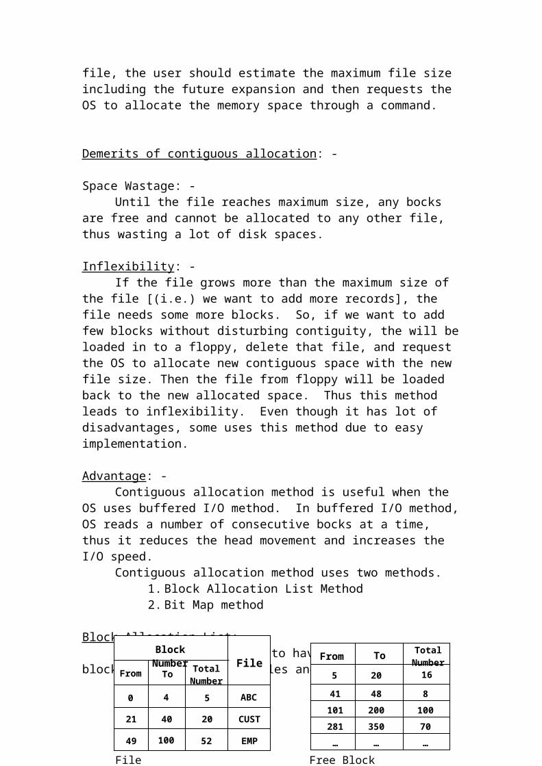
Terminal I/O: -
Terminal H/W: -Terminal is an Input/Output medium. It has 2 parts, the keyboard (O/P
medium). Sometimes, video screen may act as an I/O medium, if we use light pen, touch screen etc.,
Terminals can be dumb terminal, (or) intelligent terminal. Dumb terminal has a very limited memory, and it does no processing on the input. But the intelligent terminals can do some processing but they require powerful H/W and S/W.
TYPES OF TERMINAL: -
Memory Mapped Alphanumeric Character Oriented Terminal I/O: -
Terminals
RS-232 Memory mapped
Alphanumeric (Character Oriented)
Graphics (Bit Oriented)

Terminals have a video RAM. Video RAM is a memory, which resides inside a terminal hardware itself. Generally, the terminal screen can display 25 rows and 80 columns. So, for this type of screens, the video RAM is having 2000 data bytes (0 to 1999) and 2000 attribute bytes
All the 200 characters, stored in video RAM are displayed on the screen by the video controller. The data from the keyboard and file are moved to video RAM first and then to the monitor by the video controller.Attribute byte: -
It instructs the video controller how to display the character like bold, underlined etc., these intermations are stored in the attribute byte.
MEMORY MAPPED CHARACTER ORIENTED ALPHANUMERIC TERMINAL: -
In this type of terminal, the video RAM is treated as a part of the main memory. So, it is called memory mapped I/O. To move the data in or out of the video RAM, ordinary load and store instructions are sufficient.
DATA TRANSFER FROM KEYBOIARD TO MONITOR: -
Attribute Byte 0
Attribute Byte 1
Attribute Byte 1999
Data Byte 1
Data Byte 1999
Data Byte 1
Video RAM for monochrome
Keyboard
Memory
CPU Execute
ISR
OS Buffer
Video RAM Monitor
Interface
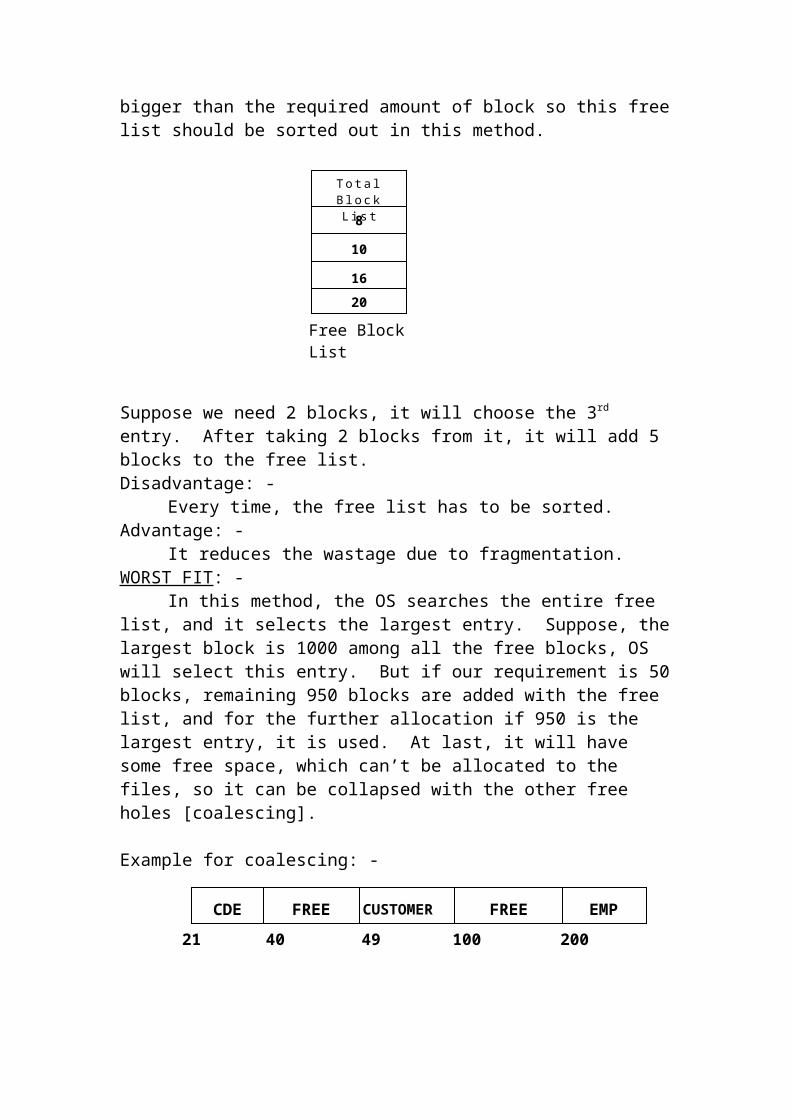
When the key is pressed in the keyboard, that character will be stored in the memory, which in keyboard and CPU is interrupted. Now the CPU executes the Interrupt Service Routine (ISR) for the keyboard. This routine, transfers the character from keyboard to OS buffer, then from OS buffer to video RAM and finally, the video controller in video RAM displays the character on the screen.
MEMORY LOCATIONS INVOLVED IN DATA TRANSFER: -
1) Small memory within the keyboard2) Video RAM3) OS buffer4) The I/O Area of Application program.
Terminal Software: -If the High Level language (HLL) program wants to print some output
on the screen, the complier of HLL generates system call and during the execution of the system call, the Os picks up the data from the memory of the application Program (AP), and transfers it to the OS buffer then from this buffer to the Terminal. If the O/P exceeds more than 1 page, the screen has to be scrolled using page up / page down keys. So, for screen handling, together with actual data, some instructions are also transferred for screen handling.
The OS has to differentiate the ordinary characters and command characters when the user types the characters; it may contain ordinary characters or command characters (like DEL key). So they cannot be sent to the memory of AP directly. Instead, it’ll be stored in a temporary memory area. From the memory, OS will detect the characters and if it is ordinary character, it will be transferred to the screen, otherwise the routines for the command characters [DEL, Tab, INS …] will be executed.
Terminal buffers and Data Structures: -OS has input buffer [To receive input from keyboard and sent to the
memory area of AP] and output buffer [To store the data sent by AP and send to the screens]. There are 2 ways to allocate the buffer space to various terminals.(a) Dedicated buffer for each Terminal: -
This scheme estimates the maximum buffer and reserves a buffer of that size for that terminal.
Buffer for Terminal 0
Buffer for Terminal 1
Buffer for Terminal 2
…………………………
Dedicated buffer for terminal

Advantage: - The algorithm for allocating/reallocating of buffer is simpler and faster.
Disadvantage: -This method wastes a lot of memory, because some terminals requires
less memory than the allocated one, whereas some other terminal requires a larger buffer, than the allocated one.
(b)Central pool of buffers: -In this scheme, the OS maintains a central pool of buffers and allocates them to various terminals when required. It is flexible, and reduces memory wastage. But the disadvantage is, the algorithm to implement this method is more complex.The buffer is divided into a number of small physical entities called character blocks [C blocks]. A C block is having fixed length collection of C blocks are said to the C list. C blocks are used to store the ASCII values for both ordinary and control characters. The C blocks assigned to a C list need not be the adjacent ones. If the size of the C block is small,
a) Number of C blocks increasedb) Searching time will be increasedc) List of C blocks will be mored) Wastage is reduced.
If the size of C block is large,a) Number of C blocks decreasedb) Searching time decreasedc) List of C block decreasedd) Wastage is increased
C block Format: -
Cblock Numberrrber
Next Pointer
Start Offset
Last Offset
Bytes…
0 7654321
Cblock Format
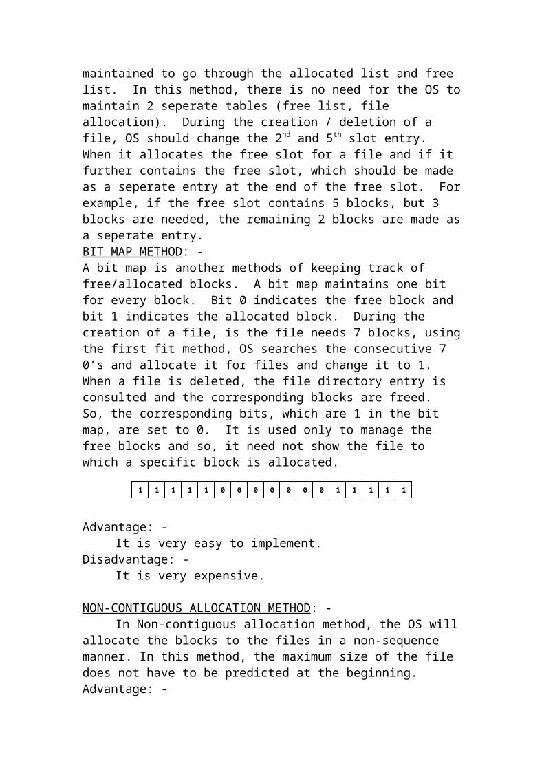
C block Number: - It is a serial number of the block.
Next Pointer: - It gives the C block number of the next C block allocated to the same C list. ‘*’ Indicates the end of the C list.Start offset: -
It gives the starting byte number of the valid data.Last offset: -
It gives the byte number of the last byte in the C block
INTER-PROCESS COMMUNICATION
When several processes need to communicate with one another simultaneously it requires proper synchronization and they use the shared data reducing in shared memory location. This method of communication is called Inter Process Communication (IPC). Example for IPC is producer consumer problem.Process Synchronization: -
Producer, Consumer problem is example for process synchronization.The producer process gets the input from the user and stores it in a
shared memory variable. The consumer process read the shared data from the producer process and prints it. In this producer consumer problem, process synchronization is needed, because if the producer process read the number then only the consumer process can print it. In the same way, when the consumer process prints it, the producer process should not read the next no to avoid overwriting (due to the shared variable). Thus process synchronization is needed.
METHODS TO ACHIEVE SYNCHRONIZATION: -To achieve this, apart from a shared variable to hold the nom, we should
have another flag variable either 0 or 1. After reading a no the value of the flag is set as 1, if the producer process read the no. So no producer process should read a new no if flag = 1. Similarly, the consumer process will print the no if flag=1 and set the flag to 0. Again no consumer process prints the no if flag= 0.
Cblock Numberrrber
Next Pointer
Start Offset
Last Offset
Bytes…
0 7654321 8
0P 1U N K E MJ4 8
Start and Last Offsets

Disadvantage: -1. Assume that flag = 0, so, process (PA) executes the
instruction P1 and it reads the number. At this time, if the time slice is over for PA and scheduler allocates the same producer process PB (instead of consumer process). PA-> ready and PB -> running and PA -> flag = 0.
2. So, PB also reads the no and over write the shared variable, causing the previous data to lost. So, the following modified algorithm is used.
Modified Producer – Consumer Algorithm: -
In the above-modified algorithm also, the problem does not solve for the following sequence.
1. Initially flog = 0.2. When PA executes the instruction P1, if its time slice is over,
processor is allocated to producer process PB.3. Since the flag = 1 [when pa executes P1 flag becomes 1] PB
wants at P0 until its time slice is over.4. When PA is scheduled, it can it print any value with out reading
any number.So, the result is unpredictable, because 2 or more processes are reading or writing shared data. This connection is called race condition.
(Will read if flag = 0)Producer Process
BeginP0: While Flag = 1 do; /waitP1: Read the Number;P2: Set Flag = 1
End
(Will read if flag = 1)Consumer Process
BeginC0: While Flag = 0 do; /waitC1: Print the Number;C2: Set Flag = 0End
Producer Process
BeginP0: While Flag = 1 do; /waitP1: Set Flag = 1P2: Read the Number;
End
Consumer Process
BeginC0: While Flag = 0 do; /waitC1: Set Flag = 0C2: Print the Number;End

The race condition occurs because one or more statement in any program, which accesses a shared variable, called critical section or critical region at the same time.
Definition for critical section: -One or more statements in any program, which accesses a shared
variable is called a critical section or critical region.Critical section: -
When several processes access and manipulate the same data concurrently the result of the execution is ambiguous. This is called race condition occurs because more than one process in the critical region at the same time.Definition for critical section: -
The part of program, which accesses a shared data, is called a critical section or critical region.
To avoid the race condition only one process is allowed to be in its critical section at a time. Another process comes out of its critical section. This is called mutual exclusion. So, each process should get permission to enter in to the critical section. The code, which implements this request, is called Entry section.
Other Operations.Entry-section
Critical regionExit section
Remainder section.
Requirement of critical section problem: -
(1) Mutual Exclusion : -If the process Pi is executing in its critical section then no other process can be executed in its critical section.
(2) Progress : - If no process is in its critical section then the process, which is not in its remainder section is allowed to enter in to its critical section.
(3) Bounded waiting : -There is a (time) limit (Bound) on the no of times for a process to enter in to its critical section.
While Counter = n do;Buffer [i] = item;i = i++;
Counter = counter + 1;
While Counter = 0 do;Item = Buffer [i];i = i++;
Counter = counter - 1;
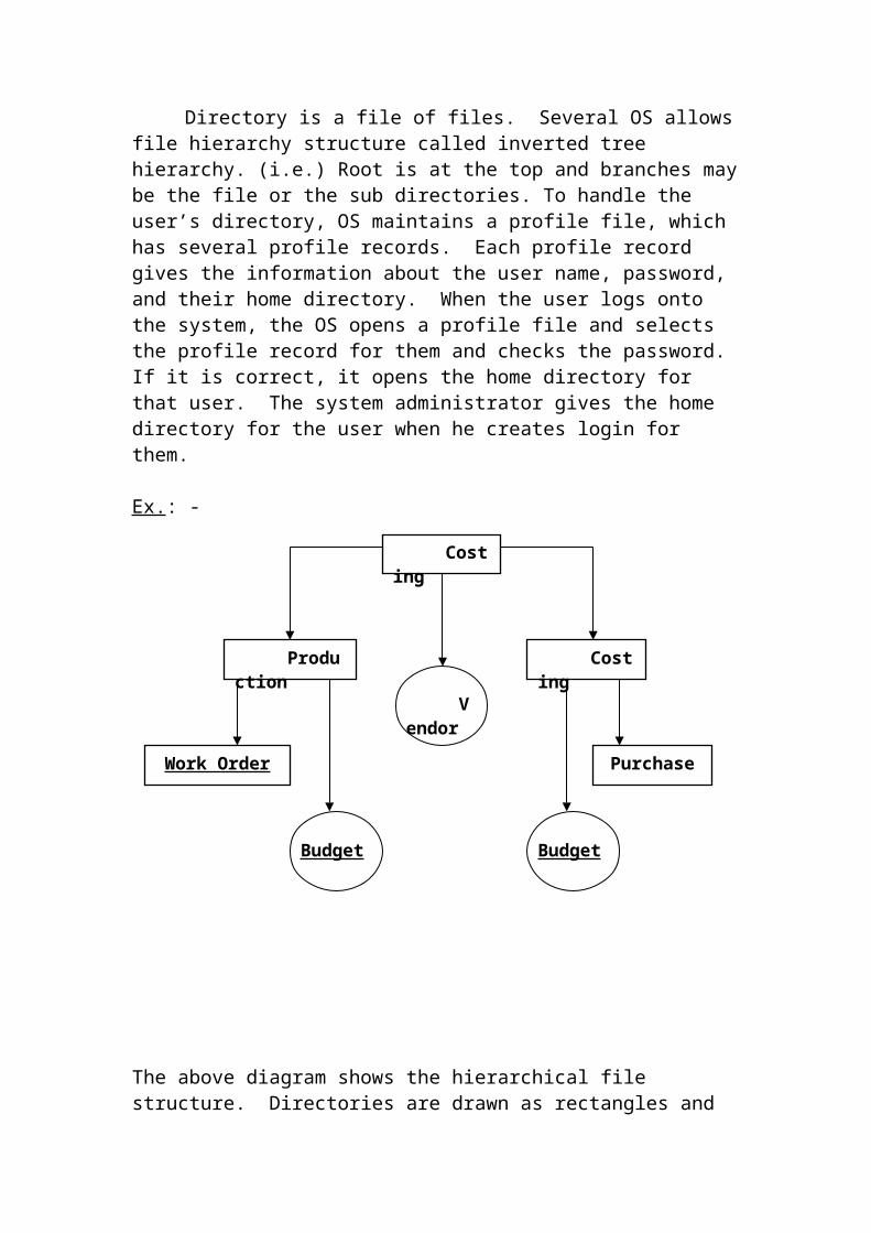
(4) To make only on process to enter to its critical section the solution should be implemented using S/W only. Portability will not be there, if the solution is implemented using H/W.
(5) Indefinite postPonement for any process should be avoided.
(6) Any process operating outside the critical region should not prevent another process from entering in its critical section.
Solutions: -(i) Interrupt Disabling / Enabling :
One solution is to disable all interrupts before any process enters the critical region. If all interrupts are disabled, the time slices of the process, which enters its critical section will never get over until is come out of its CS. So, no other process can enter in to the CS.
Other instruction
Remaining instructionThe problem with this solution is, if a process in the CS executing
infinite loop, then the interrupts will never be enabled and no process can proceed.
(ii) Lock-flag : -One variable called Lock-flag is used which has 2 values ‘F’ or ‘N’. If any process is in its CS, this variable is set to ‘N’ [Not Free]. If no process is in CS, it is set to ‘F’.Algorithm:
This Algorithm doesn’t satisfy the mutual exclusion.
(i) Initial Lock-flag = ‘F’.
(ii) So, it comes to P1 statement and before executing it, the time slice is up, lock-flag remains to be ‘F’.
(iii) PB is scheduled and since lock-flag = ‘F’, it executes P1 and sets lock-flag as ‘N’ and enters in to the critical section and in the middle it loses the control of the CPU as its time slice is up.
Disable interruptsCritical sectionEnabling interrupts
Begin P0: While lock-flag = ‘N’ do;P1: Set Lock-flag = ‘N’;P2: Critical SectionP3: set Lock-flag = “F’;End.

(iv) PA is scheduled again and it resumes from P1, it sets lock-flag as ‘N’ and also enters into the critical section.
Algorithm which implement mutual exclusion: -
Peterson’s Algorithm: -It is based on 2 processes it uses 3 variables.
Initially PA-TO-ENTER = “NO”, PB-TO-ENTER = “NO” AND CHOSEN PROCESS = “A”.
1. Let us assume that PA is scheduled first.2. By executing A0, A1, PA-TO-ENTER =”YES” and CHOSEN
PROCESS = “B”, PB-TO-ENTER = “NO”.3. Since A2, A3is false, it will execute A4 and PA enters into its critical
region.4. Lets us assume that time slice for PA over and PB are scheduled now.
But still PA is in its critical region.5. PB will execute B0, B1 to set PB-TO-ENTER to “YES” and chosen
process to “A”. PA-TO-ENTER is also “YES”.6. At B2, it will wait because both the conditions are met. Thus PB is
prevented from entering its critical section.7. When PA is scheduled again after coming out of its CS, it set PA-TO-
ENTER = “NO”.8. Now, if PB is scheduled again, it will execute instruction B2, B3 and
enter its critical section. It happened only after PA comes out of its CS.
Peterson’s algorithm is simple. But more than 2 processes are not allowed this algorithm.
Hardware Assistance: -To implement mutual exclusion, some computer hardware has a special
instruction called “Test and Set Lock (TSL)” instruction. This instruction has the format “TSL ACC, IND” is the accumulator register and IND is the name of the memory location, which hold a character to be a flag (or) indicator. Actions for TSL instruction are,
BeginA0: PA-TO-ENTER = “YES’;A1: CHOSEN-PROCESS = “B”;A2 WHILE PB-TO- ENTER=“YES”ANDA3: CHOSEN-PROCESS = “B” DO;A4: CRITICAL REGION A;A5: PA-TO-ENTER = “NO”;End
BeginB0: PB-TO-ENTER = “YES’;B1: CHOSEN-PROCESS = “A”;B2 WHILE PA-TO- ENTER=“YES”ANDB3: CHOSEN-PROCESS = “A” DO;B4: CRITICAL REGION B;B5: PB-TO-ENTER = “NO”;End

1. Copy the contents of IND to ACC2. Set the contents of IND to “N”.
Implementation of mutual exclusion using TSL instructions: -Let us assume that IND takes the value “N” (indicates critical section is
being used currently (i.e.) it is not free) or “F” (CS is free). When it is “F”, a process can in to the critical section. If IND = “N”, no process can enter its CS because some other process is already is in its CS.
ENTER / EXIT ROUTINES: -
Enter critical regionEN0: TSL ACC, IND // IND -> ACC, “N” -> IND EN1: CMP ACC, “F” // CHECHK IS CS FREEEN2: BU ENO // Loop lock if in useEN3: RTN // Return t caller & Enter CS
Exit CSEXO: MOVE IND, “F” // “F” -> IND EX1 RTN // Return to caller
Mutual Exclusion With TSL0. Initial portion1. Call Enter-Cs2. Critical section3. Call Exit-CS4. Remaining portion.
Initially IND = “F”(i) PA is scheduled.(ii) Instruction 0 is executed and through instruction
1, enter CS is called.(iii) Instruction ENO is executed. NEW ACC
becomes “F” and IND = “N”.(iv) Instruction EN1 is true, so it returns to the caller
program by executing EN3.(v) Assume that Pa loses control to PB after entering
in to CS.(vi) PB now executes instruction 0.(vii) PB executes instruction 1 and so calls ENTER-CS
routine for PB.(viii) ENO is executes for PB, ACC becomes “N” and
IND = “N”.(ix) EN1 is executed for PB and condition is not
satisfied, so it goes to EN0 and doesn’t get out of the ENTER-CS routine, so PB cannot reach

instruction 2 and enter its CS. Because PA is in its CS.
(x) PA is scheduled again, when it completes instruction 2, it will come out from CS.
(xi) Now PA executes instruction 3 and calls Exit-CS routine.
(xii) EX0 is executed for PA where, IND becomes “F”, by executing EX1, PA comes to the main program.
(xiii) Suppose PB is scheduled again, it calls ENTER-CS and executes EN0, EN1 and its enters in to its CS.
Demerits of this algorithm: -
1. It uses special H/W so it cannot be generalized to all the machines.2. It is based on the principle of busy waiting. So, it is not the most
efficient solution. So the semaphore concept is introduced to tackle most of the problems.
Semaphore: -A semaphore is a protected variable, which can be accessed and changed
by only 2 operations called “DOWN“ (P) and “UP” (V).[Verhogen -> To increment Problem -> To tests]Types of semaphore: -
1. Counting semaphore (or) General semaphore : -The value of this semaphore may be +ve value.
2. Binary semaphore : -It can be have only 2 values either 0 or 1.
Semaphore can be implemented using H/W (or) S/W.
General Structure of a process with semaphores: - Down & Up operations form the mutual exclusion primitives for any process. So, if a process has a CS, it should be encapsulated between DOWN & UP instruction.Semaphore Algorithm: -
Begin 0. Initial routine;1. DOWN (S);2. Critical-region;3. UP (S);4. Remaining portion.
End.
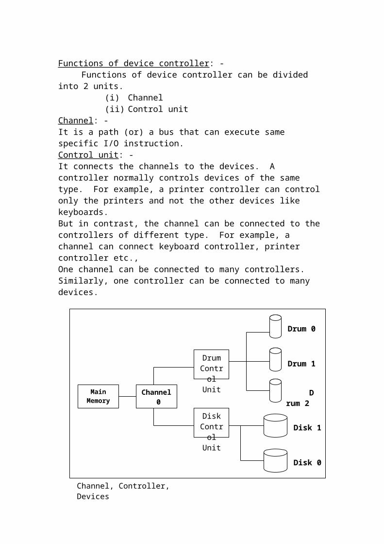
The DOWN (S) & UP (S) operations ensure that only one process is in its CS. All other processes waiting to enter in to there are kept in a queue called a “Semaphore Queue”. The queue has a queue header and all PCBs are chained. The OS can traverse through all the PCBs. When one process comes out in its CS, the OS allow a new process to release from the Semaphore queue.
DOWN (S) & UP (S) are indivisible instruction on a uniprocessor system to avoid context switching during the execution of DOWN (S), UP(S), DI, EI instruction are used on multiprocessor computers, H/W instruction TSL is used to implement indivisibility.
DOWN (S): -> Uniprocessor system
BeginD0: Disable interrupts
D1: If s>0 then s=s-1D2: Else wait on S
D3: End if D4: Enable interruptsEnd.
Wait on S means moving the PCBs if a running process in the semaphore queue ‘S’ are a binary semaphore. So, S a may be 0 or 1. A process can enter its CS if s=1.UP (S):
Begin U0: Disable interrupts
U1: s = s + 1U2: If semaphore queue NOT emptyU3: then release a processU4: End if U5: Enable interrupts
End.
“Release a process” in UP (S) indicates that moving the first PCB from the semaphore queue to the ready queue.
Working Principle of Semaphore Algorithm: -Assume that s = 1 and there are 4 processes PSA, PB, PC and PD in the
ready queue. Let us assume that PA gets scheduled and dispatched first.
1. PA executes instruction 0.2. PA executes instruction 1 in main.
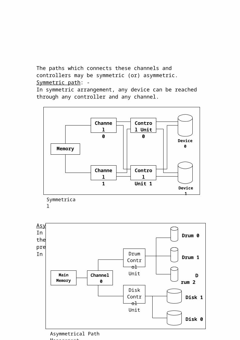
3. By executing instructions 1, the DOWN (S) procedure is invoked. It disables the interrupt. It checks in D1, if S>0 and if so s = s –1 in D2 now s = 0. It enables the interrupt.
4. PA starts executing instruction 2 in main program and PA enters in to the critical section.
5. Assume that time slice for PA gets over. While it is in the CS and PA moved from running to ready state.
6. Assume PB is now dispatched to the CPU.7. Now PB calls the DOWN (S) routine. In that routine, it will check S
value and since s = 0, PB is added to the semaphore queue.8. Since PB is in its waiting stage, PC is scheduled now.9. PC again called DOWN (S) and it is also added to the semaphore queue.10. Since PA is in its CS, all other processes PB, PC cannot enter in to CS
and they are added to the semaphore queue. These processes can enter in to CS only after PA comes out from CS and executes UP (S).
11. Assume PA is reduced and completes its CS.12. It calls UP (S) routine. This routine makes S as 1 and it checks the
semaphore queue and finds that it is not empty.13. So UP (S) routine releases PB from semaphore queue and moves it to
the ready queue. But PC is still in the semaphore queue.14. PB is now scheduled and the same procedure is repeated until all the
processes are order.15. [Suppose instead of scheduling PB, if PD is scheduled (due to its higher
priority) it enters in to the CS. If its time slice is over when it is in CS and PB is scheduled again, it won’t enter in to the CS but it again enters to the semaphore queue].

MEMORY MANAGEMENT (MM)
MM module is used to perform the following functions.
a) It keeps track of all memory locations-free or allocated and if allocated to which process and how much.
b) To decide the memory allocation policy i.e., which process should get how much memory?
c) To use various techniques and algorithms to allocate and reallocate memory locations.
Contiguous
Real Memory Management
System
Single Contiguous
MMS
Variable Partitioned
MMS
Fixed Partitioned MMS
MMS – Memory Management System
Non-Contiguou
s,Real Memory Management
System
Paged MMS
Combined MMS
Segmented MMS
MMS – Memory Management System
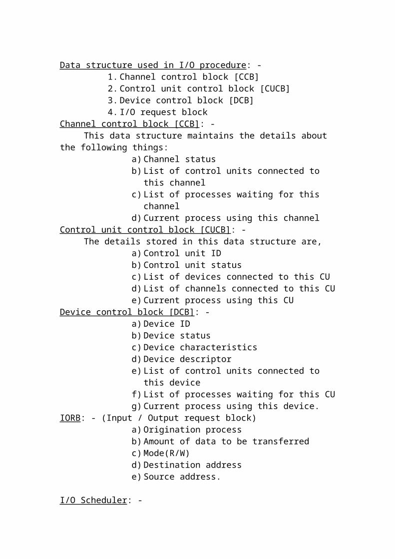
NOTE: -
In contiguous Scheme, the program will be loaded into the memory in a continuous manner. But in non-contiguous the program will be divided into different chunks and to be loaded at different portions of the memory. In paging, these chunks are of same size, but in segmentation they can be of different sizes. In real memory management, the full process image is expected to be loaded in the memory before execution but in virtual memory, it starts executing a process even with only a part of the process image loaded in the memory.
SINGLE CONTIGUOUS MEMORY MANAGEMENT: -
In this method, the physical memory is divided into 2 areas. One is permanently allocated to the OS (monitor). At any time, only one user process is in the memory and after its completion, the next process is brought in the memory. The loading of process to the memory will be done as follows.
a) All the ready processes are held on the disk, and the OS holds their PCB in its memory in the order of priority.
b) At any time one of them run in the main memory.c) When it is blocked, it is swapped out from the main memory to the disk.d) The next highest priority process is swapped in the main memory from
the disk and it starts running and hence only one process in the main memory when if it is a multi-programming.
PROBLEMS OF THIS SCHEME
Non-Contiguous, Virtual Memory
Management System
VirtualMMS

a) Relocation/Address Translation: -
At the time of compilation itself, the starting physical address of the program is known. So the problem of relocation in address translation does not exist. The executable program contains absolute address only. The do not need to be changed or translated during execution.
b) Protection And Sharing: -
Protection refers to the prevention of one program from interfering with other program. It can be achieved by 2 methods.
i) Protection bits ii) Fence register
Protection Bits: -
A single bit is reserved for each memory word to represent whether this work belongs to OS or application process. In a 32 bit work length computer, 1 bit is reserved for each work for protection. If this bit is 0, the word belongs to the OS and if it is 1, the work belongs to the user process. The mode bit [ hardware bit which represents whether the system is in the user mode or in the system mode (monitor mode), and the protection bit should be equal. Thus at any time, when the user process refers to memory locations within the OS are, the hard ware can prevent it from interfering with the OS, because the protection bit is 0, but the mode bit is 1.
Fence Register: -
OS(Monitor)
User ProcessArea
0
P
max
Single cont iguous MM
OS(Monitor)
User ProcessArea
0
P
max
Fence

This is the CPU register. It contains the address of the fence between the OS and the user process. The address in (Fence register address = P) MAR is compared with the fence register by the hardware itself and the hardware can detect any protection violation is there.
FIXED PARTITIONED MEMORY MANAGEMENT: -
In this scheme, the main memory was divided into various sections called “Partitions”. These partitions are of different sizes but the size is decided at the time of system generation and they could not be changed. To change the partitions, the operations have to be stopped and the OS has to be generated with different partition. So these partitions are called “static partition”.
The OS maintains partition
This partition id will be stored as a process id in PCB of each process. For Example, Process ID for Process A in its PCB will be 2.
PartitionID
StartingAddress
PartitionSize
Status
0 0 100 Allocated1 100 200 Free2 300 100 Allocated3 400 300 Allocated4 700 100 Free5 800 200 Allocated
OS
Process A
Process B
Process C
0k
100k
300k
400k
700k
800k
1000k
P0
P1
P2
P3
P4
P5

During the Partition to a process, the following 5 things will take place.
1. Long-term scheduler of PM selects the process from the hard disk, which is to be brought in to the memory next.
2. It then finds out the size of the program to be loaded by consulting the IM portion of OS.
3. A request is placed to the partition allocation routine of the MM to allocate a free partition with the correct size.
4. With the help of the IM module, it now loads the binary program in the allocated partition.
5. Now the partition ID is given as the process ID in its PCB before the PCB is linked to the chain of ready process using PM module of OS.
6. The routine in the MM marks the Status of the partition as “allocated”.7. PM now scheduler this process.
Allocation algorithms for fixed partitioned MM: -
The strategies of partition allocation are,
i) First fitii) Best fitiii) Worst fit
The OS holds the processes waiting to be loaded in the memory in a queue. There are 2 methods of maintaining this queue.
1. Multiple Queue2. Single Queue
Multiple Queue: -
In this queue, there is one separate queue for each partition.
Queue 2
……. 3k 4k 5k 3k
Queue 1
……. 6k 7k 6k 8k
Queue 0
……. 1k 2k 1k 2kOS
2k
8k
5k
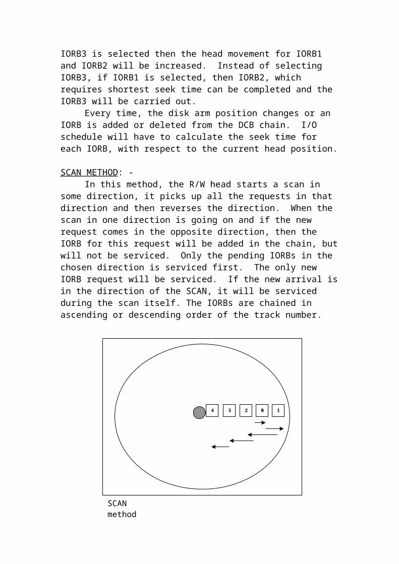
Queue 0 will hold process with size of 0k-2k; queue2 will hold processes with size between 2k-5k; & Queue 1 will hold process with size between 5k-8k etc.
When a process wants to occupy memory, it is added to a proper queue depending upon the size of a process.
Advantage: -Very small process is not loaded in a very large partition. Thus it avoids
memory wastage.
Disadvantage: -There is a long queue for smaller partition and the queue for bigger
partition could be empty.
Single Queue: -
In this method only one queue is maintained for all the ready process. Based upon the scheduling algorithm, all the PCBs of ready process are chained.
If the PCB at the head of the queue requires memory, which is not available now, but that memory can fit the process represented by the next PCB in the queue, then the OS can change the sequence of selecting the process. For instance, in the above figure, if the partition with size 5k is free, the highest priority process at the head of the queue with size 7k can’t be dispatched. The OS has to use the appropriate method to find the next process to dispatch.
OS
2k
8k
5kTail
3k 8k 5k 2k 7k 6k
Head
Queue
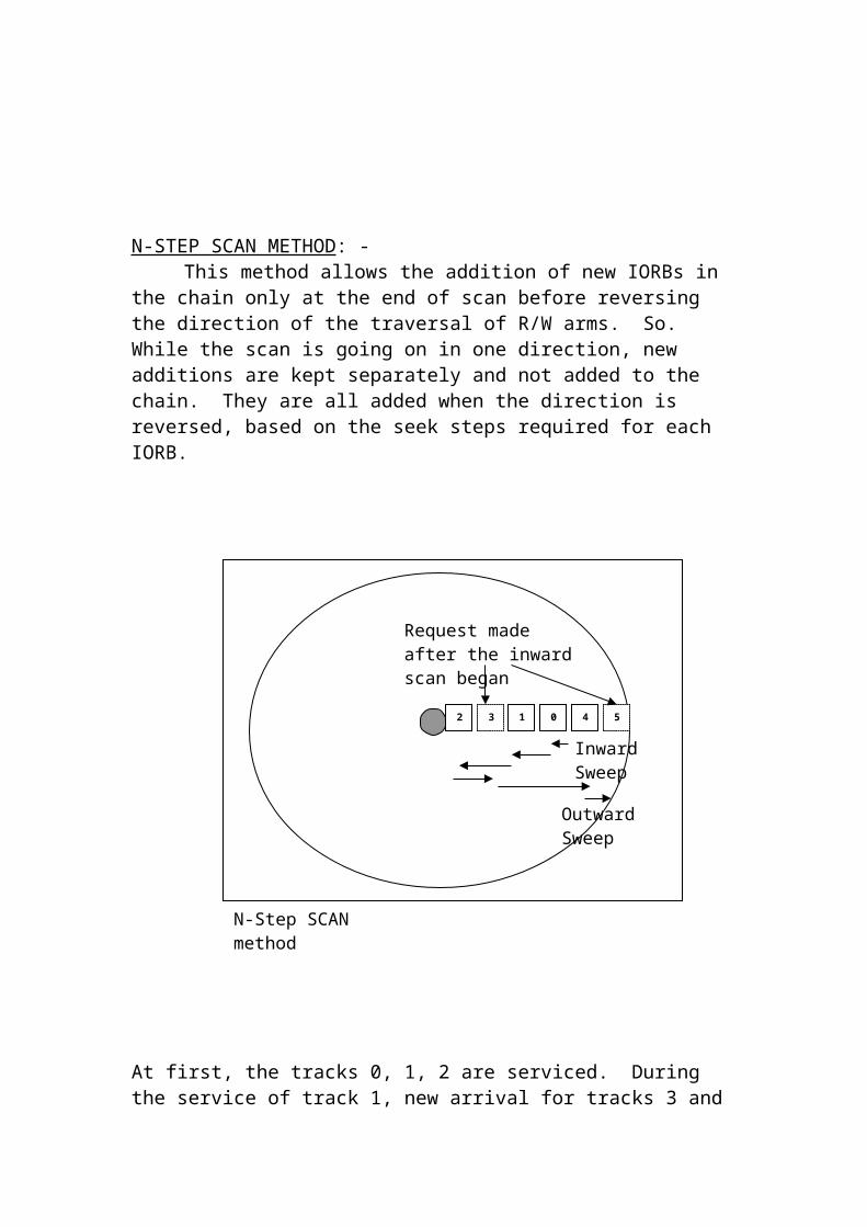
Problems Involved on Fixed Partition Relocation and Address Translation: -
When a program is complied, it is assumed to be at the starting address 0. This address. But in reality, this program may be loaded at different memory locations, which are called physical address. So MM module provides the method of address translation and relocation to map the virtual address into physical address.
Eg:-LDA 500 should be converted in to LDA 1500.
Address Translation must be done for all instruction except for constants two types of address translation.
a) Staticb) Dynamic
Static Relocation of Address Translation: -
During the loading of the program in the memory, relocation & Address Translation will be done by relocating linker (or) a relocating loader. In this method, the complier complies the program assuming that the program is to be loaded in the main memory from 0. The loader takes the object code (Complied code) & starting address of the partition of the partition as a parameter, and the linker goes through each instruction and changes the address in each instruction before it is executed. The linker should know which portion of the instruction is an address. Based upon the type of instruction and addressing mode, loader should decide whether to change it or not.
Disadvantage: -
1. It is a starting address of the partition – slow process.2. It is very expensive.
Dynamic Relocation: -
Complied Program
Relocating Linker/Loader
Relocated Program with
changed address
If the relocation is done during runtime, that is said to be dynamic relocation. It uses special register called base register. It contains the value of relocation.
Any instruction, which is fetched from the memory, is sent to the IR. Now the address part is separated and sends to the adder circuit along with the Base reg. Content (Base register contains the value of the relocation). Now the added is friendly send to the MAR, which is the relocated address.
When the process changes from running state to blocked state, there is no need to change the value of the Base reg., which is stored in the reg. save area of the PCB. But when the process is swapped into the memory in different partition with different address, that address should be written in to base register of the register save area of the PCB.
Protection and sharing : -
Preventing one process to interfere with another process is called protection. The approaches are –
i) Protection bits ii) Limit Register.
Protection Bits: -
In this fixed partition, 1 bit is not sufficient for protection. A few bits for each word called key bits. For eg., if the memory contains 16 partitions, 4bits are allotted as protection bits. All the partitions are having one or blocks of same size. For e.g., in a 64k physical memory, 32blocks of each 2k will be distributed evenly to 16partitions. All the blocks belong to the same partition should have the same key value.
500IR
Addressop
+
1000
1500LDA 500
0500
1000150020002500Adder
MAR
PhysicalAddress
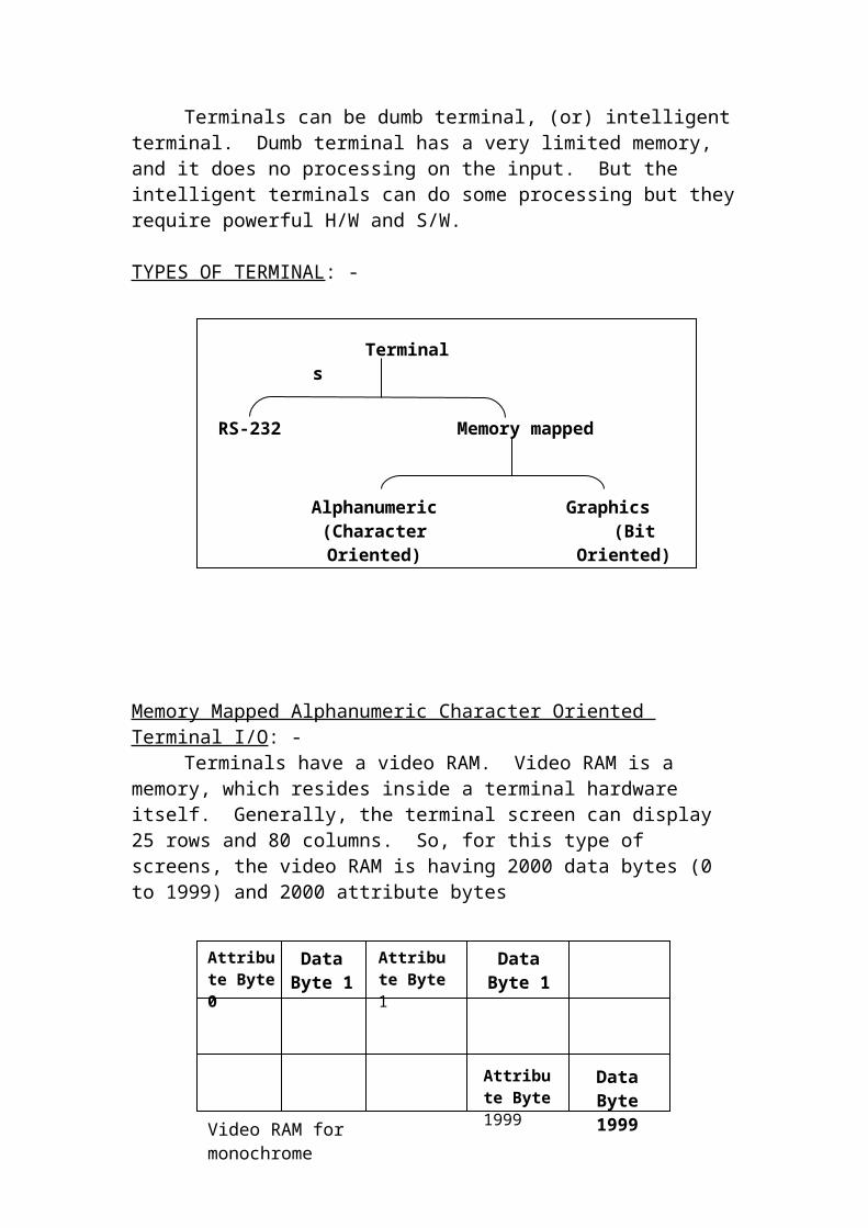
How to Protect: -
When a process is loaded in to the partition the key value for that partition is stored in program status word (PSW) [CPU reg.]. After the exact memory reference the 4 protection bits are retrieved and compared with PSW. If it is equal, it means that the process is accessing the address belonging to the exact partition; otherwise it tries to access the address of it other partition.
Disadvantages: -
1) Internal fragmentation is more2) It limits the maximum no of partitions.3) It doesn’t allow easy sharing (i.e.) A process cannot access more
than one partition.
Limit Register: -
It provides another method of protection, which holds the last virtual address of the program. The virtual address of the program should be within the bounds of the process address space. For instance, when the program size is 1000, the virtual address ranges from 0 to 999. So the limit register value should be set to 999. Every virtual address will be checked to ensure that it is less than or equal to 999 then added to the base register. If it is not within the bounds the H/W will generate an error message.
Partition 0
Partition 1Partition 1
Partition 2Partition 2
Partition 15
0000
00010001
00100010
1111
2k
4k
8k
2k
<=Limit reg.
Address From IR
No
Yes+
Base Reg.
MAR
Adder
MainMemory

Sharing: -1) It keeps copies of the sharable in partition. But it is wasteful.2) Another way is to keep all the sharable code and data in one
partition. But it is complex.
Variable partition: -
Fragmentation, restrictions on the number of resident processes are the problems associated with fixed partition. These problems reduce the degree of multiprogramming & CPU utilization. So variable partitions are introduced to overcome these problems. In variable partitions, the no of partitions and their sizes are variable. They are not define at the time of system generation.
At any time, any partition of the memory can be allocated (or) Free, but the starting address of any partition in not fixed, but it keeps varying.
Diagram
The OS creates the partitions at the run time, and they differ in sizes
Allocation Algorithm: -
Allocated / Reallocated information are kept as bitmaps or linked lists.
Diagram
Memory allocation: -
Diagram
In the both these methods, we can use first fit, best fit and worst fit algorithms.
Merits and Demerits of bitmaps & linked list: -
Advantage: -Bitmaps are very fast for reallocations as follows.
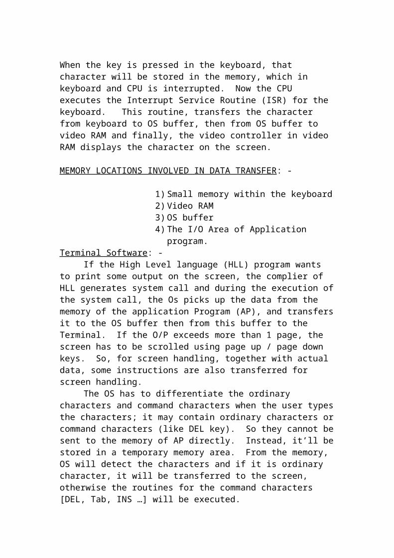
1) Access the PCB of the terminated process.2) It finds out the starting chunk no & no of chunks allocated to this
process.3) Access the corresponding bits for those chunks in the bit map & set
them to 0.
Disadvantage: -It is very slow for allocation. It has to start searching from the
beginning.
Problems involved in variable partition: - Defragmentation (or) Coalescing: -
If the holes are in a continues manner, those holes will be combined together as a single hole. This technique is said to be coalescing.
Compaction: -When the holes are in a non-contiguous manner, those can be combined
together using the method ‘compaction’. This technique shifts the necessary process images to bring the free chunks to adjacent positions to coalesce them. There are different ways to achieve compaction. The OS has to evaluate these alternatives internally and them choose.
Diagram
Relocation and AT: -The methods are similar as in fixed partitioned.
Protection: -It provides a protection using limit register. Before calculating physical
address, the virtual address is checked to ensure that it is equal to or less than the limit register.
Sharing: -
Diagram
Sharing is possible using overlapping partitions. The process A occupies the locations with address 3000 to 6999 and process B occupies with address 6000 to 8999. The locations between 6000 & 6999 are overlapping as they belong to both the partitions.
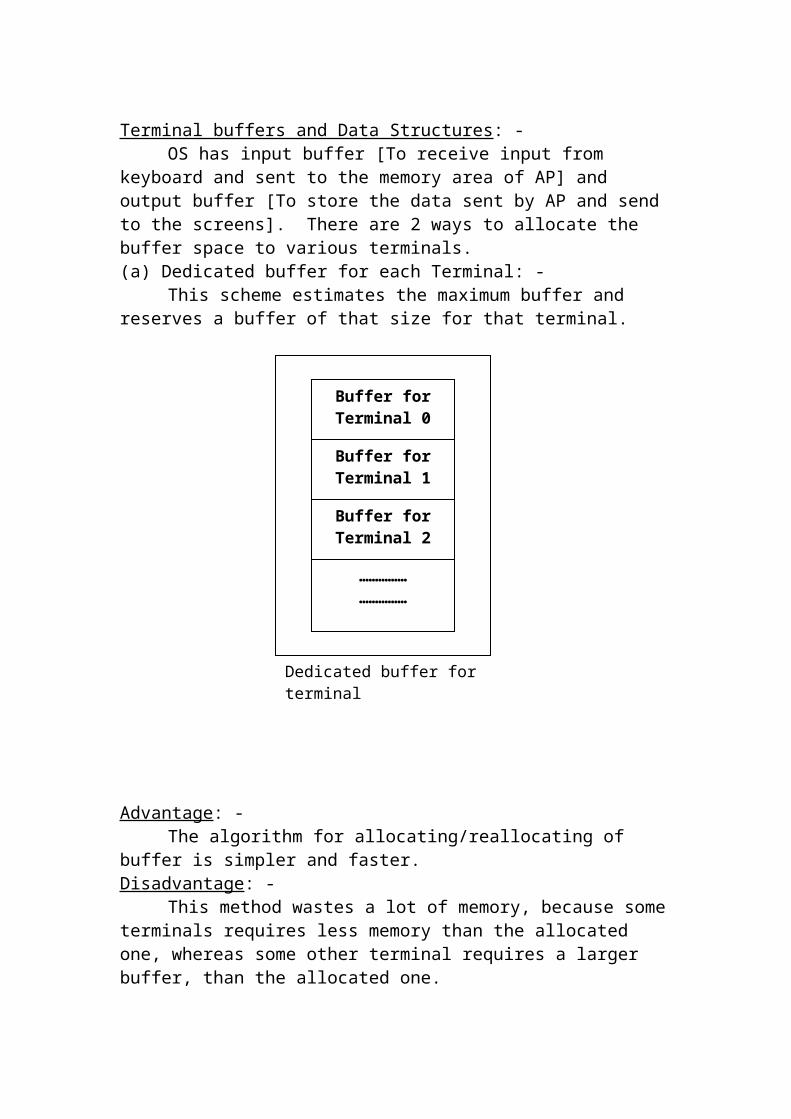
Limitations: -1) It allows sharing only for 2 processes.2) The shared code must be executed in a mutually exclusive.
Non-contiguous allocation: -If the program is stored into the various parts of the memory is called
non-contiguous allocation.
Paging: -
The chunks of memory are of same size in this scheme. In this scheme, the logical address space of a program is divided into equal sized pages and the physical main memory is also divided in to equal sized page frames. The size of a page is same as of page frame, So that the page can exactly fit into a page frame.
The paging scheme works as follows: -
i) The logical address space of a program consists of a no of fixed sized contiguous pages.
ii) The virtual address of the program contains 2 parametersa) Logical (or) Virtual page no [P]b) Displacement [D]
iii) The physical memory is divided into a number of fixed sized page frames. The size of a page frame is equal to that of a logical page. The OS keeps tracks of the free page frames and allocates a free page frame to a process.
iv) Any logical page can be placed in any free page frame. After the page [P] is loaded in a page frame [F], the OS marks the page frame as “Not free”.
v) After loading, the logical address [P, D] will be come 2 dimensional physical address [F, D]. D will be same for both addresses since, the page size is equal to the page frame.
vi) During execution, the AT method has to find out the physical page frame number [F] for every logical address [P]. The displacement value D and Page frame number [F] gives the final physical address [F, D].
Two dimensional Address: -
Let us assume that page size = 100.
0-99 Page 0100-199 Page 1
200-299 Page 2

If gives address = 107 then it is in page 1 with displacement = 7.
So physical address = 01 000111
Page Displacement No value
Page Map Table: -It contains the information that, which page frame, is allocated to which
page. It is a key to AT.
Diagram
Allocation Algorithm: - (Selecting the page frame)
1) MM keeps tracks of free PF, in addition to PMT.2) When a process is to be loaded in to the memory, PM requests IM
for the size of a program.3) IM submits the size of a process to PM, from FD (File Directory).
After getting the size, PM request the MM to allocate the memory the memory of that size.
4) MM now checks the list of free page frames and allocates them to the process. After that it will mark those pages as not free. If there is not enough memory space, the loading of the process will be postponed.
5) After allocating page frame. MM now indicates the IM to load the process.
E.g.: -List of free page frames 10,14, 15,3
Diagram
Swapping: -When one process needs to be swapped, all the pages are swapped out.
Keeping only a few pages in the memory is useless, becomes a process can run only if all the pages are present in the memory. When a process is swapped out, the PMT is also released. When it is swapped in again, it may be loaded in different page frames, and new PMT is created.
Relocation and AT: -Assume the system with the main memory of capacity 512 words. So
the memory is divided into 16 pages of 32words each. Hence we need 4 bits

(16 pages) to represent page number and 5 bits (32 words) to represent the displacement D (0 to 31). So total no of bits in the address will be 9 bits.
Diagram
E.g.: -Consider the instruction LDA 107, which is stored at the logical address
50. During fetch cycle to convert this logical address into physical address, the OS will refer PMT and it show page 1 is mapped onto frame 4 at D = 18. Frame 4 contains physical address 128 to 159. Therefore LDA 107 will be placed at 128 + 18 = 146 in decimal (or) 010010010 in binary.
At the execution cycle, for LDA 107 again address translation will be done. PMTLR contains the no of pages in a process. During runtime the no of pages from PCB will be moved to PMTLR. It is used to detect invalid reference.
Implementation of PMT: -
(i) S/W Method (ii) H/W Method(iii) Hybrid Method
S/W Method: -PMTLR is register, which contains the no of pages in the main memory.
The address of PMT is stored in PCB. During context switch the address is loaded from PCB into another CPU register called PMTBR. This register is used to locate the PMT in the memory. During swap out & swap in of a process, a new PMT is created and PMTBR also changed.
One word is reserved for each PMT entry. If PMTBR = 500, then the entry for the virtual page no 8 is 500 + 8 = 508.
Diagram
H/W Method: -This method uses no of associative registers (or) associative memory
(or) look ahead memory, look ahead buffer (or) context addressable memory (or) cache. The table search is done by the H/W itself and hence it is very fast.
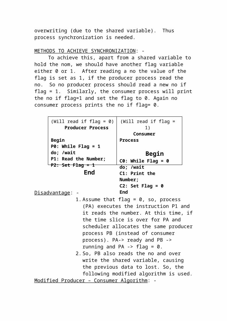
Diagram
Hybrid method: -In this method, it has small no of (8,16) associative registers. It reduces
the cost.
Protection and sharing in paging: -Protection in paging system is achieved by the PMTLR register. But this
register ensures that the reference is made in the address space only. Protection at the level of the page can be provided using “access protection bits” which are added to each PMT entry. For each page access rights like Read only (010)’ Read write (011) can be defined. But it is difficult, to implement. So protection in paging can also be achieved by protection keys sharing: having only one copy of the program in the memory, which is used very often by multiple users, will provide Sharing. This is saver memory For example, compiler, an editor; several users for different processor may use a word processor. So only one copy of the compiler, editor word processor will be in the memory, which is shared by several processors.A program consists of code is data parts. All the processes can share the coding area but all can’t share the data area. For instance, there are several users using the editor but editing different files. So the data area for the certain process will contain a page from another file. Hence the data area cannot be shared. It is only the coding area (editor) that can be shared. Sharable code is called ‘reentrant’.
Ex: - Let us assume that there are 3 users using the editor to create different program. Assume that the editor has 4 pages of code, which are sharable. It also has 1 page of data area, which cannot be shared.
Diagram
Segmentation:In segmentation, the program is divided into several pages but the size
of the pages will not be equal. They are of different sizes. For example, the program consists of 3 major segments code data and stack. The code segment also has several sub segments like main program, library function and built in functions.
Diagram
Each segment is compiled with respect to as the starting address. The compiler/linkage editor will do the following things.
Recognizes different segments. Numbers them.
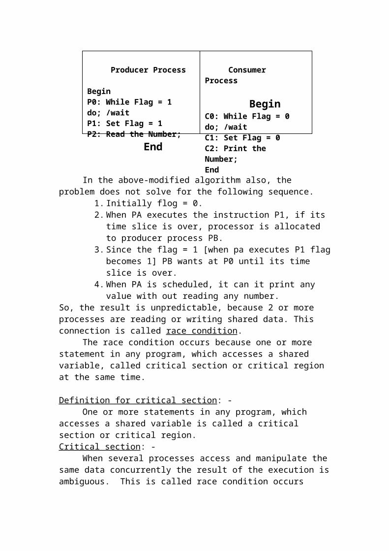
Builds the segment table. Produces an executable.
and their segment numbers.
So for the above virtual address 2520, the segment number S=3, and D=20.
Diagram
(1) The high order bits representing S are then out from IR to form the input to the SMT as an index.
(2) The OS now stores the segment size Z=900 and starting address B=6100 for the segment number=3 entry from SMT.
(3) The displacement should be les than the segment size. So, D is compared with Z to ensure that D<=Z. If not, the hardware itself generates an error.
(4) If D is legal, then the OS checks the access rights and ensures that whether it can be accessible.
(5) If it is accessible now the effective address is calculated as (B+D).(6) This address is used s the actual physical address.
Register used in Segmentation: -
SMTBR: - Each process has one SMT. The OS stores SMT in the memory. So the starting addresses.
Assigning 2 dimensional addresses.The logical address consists of a segment number (S) and offset (D). If
virtual address is 1100 then it is in segment 1 and displacement 100. (i.e.) S=1, D=100. In segmentation, the compile itself has to generate a two dimensional address. This is different from paging. In paging, the binary term of virtual address and physical address would be same because the page size I an exact power of 2. But in segmentation the segment size is unpredictable and so the address should be represented in 2 dimensions term.
Diagram
Virtual Address
0-999 1000-1699
1700-2499
2500-3399
3400-3899
Segment Number
0 1 2 3 4

Based on the number of segments number of address bits allotted for representing segment number will be differing. For example if the system containing 8 segments, 3 bits are allotted to represent segments. During the process invitation, the following steps are followed.
(1) The OS keeps track of the chunks of free memory.(2) When a new process is to be created, the PM gets; the information
bout the number of segments and size of the process from IM, and pass this information to the MM.
(3) MM now consults the information about free memory and allocated it for different segments using first fit, best fit (or) worst fit.
(4) After the memory is allocated it builds a segment Map table (SMT) (or) segment descriptor Table (SDT), which contains segment number, size, base, and Access rights.
Address Translation and relocation: -
The SMT is used for add translation. Let us assume the virtual add to be translated is 2520. Consider the following virtual address of SMT is stored in ‘segment map table base register’ (SMTBR).This register stores the maximum number of segments in a process. A logical segment number (S) can be validated against SMTLR before getting into the SMT, as an additional protection.
SMT size depends upon the maximum number of segments allowed in a process. It this number is very small, SMT can be held in the hardware register to improve the speed. It is very large, it can be held in main memory.
Protection and sharing: -Sharing of different segment is similar to that in the paging and is simple. Consider the editor program, which has 2 code segments and one data segment.
Diagram
The coding areas for both processes are same and only the data area differs for them. So size and base values for code segments 0&1 are the same in both SMT.
Protection: -Protection is achieved by defining access rights to each segment such as
‘Read only’ (or) ‘Read/write’ (10). These access rights bits re stored in SMT. The OS sets up these bits in SMT while creating it, for a process. If there are 4 processes sharing a segment, all the 4 SMTs for those 4 processes will have same Base (B) and size (Z) but access rights can be different for these 4 processes. It may have “RO” & same other may have “RW”.

Combined Systems: - [paging, segmentation]
The combined system are, combining both paging and segmentation technique. It requires a 3 dimensional address consisting of segment number (S), a page number (P) and displacement (D). There are 2 possible schemes in these systems.
*Segmented paging as in IBM/360 (or) Motorola 68000 systems. In this scheme, the virtual address space of a program is divided into a number of logical segments of verifying sizes. Each segment is divided into a number of pages of same size.
Paged segmentation as in Ge645/MULTICS –In both the cases, both the segment map tables (SMT) and page map tables (PMT) are required of these two schemes segmented paging is more popular.
Segmented paging: -
1) The program consists of various segments and the details of each segment are represented by SMT. Each segment is divided into a number of pages of equal size, whose information is maintained by PMT. If a process has 4 segments, there will be 4 PMTs one for each segment.
2) Various fields in the SMT in this combined scheme is different. For example, the size field in SMT gives the total number of pages. Similarly, the base (B) in the SMT gives the starting word address of the PMT for that segment, instead of starting address of the segment itself virtual address.
Diagram
Working Principle: -
(1) The logical address consists of 3 parts, segment number (S), Page number (P) and displacement (D).
(2) SMTLR holds the number of segments and SMTBR holds the starting address. Their values will be different for the SMT if each process.
(3) The segment number is validated against SMTLR and added to SMTBR to get an index to the SMT.
(4) From that appropriate SMT entry, the page number is obtained and is validated against the segment size (Z), which gives the maximum number of pages for that segment.
(5) After that access rights are validated.
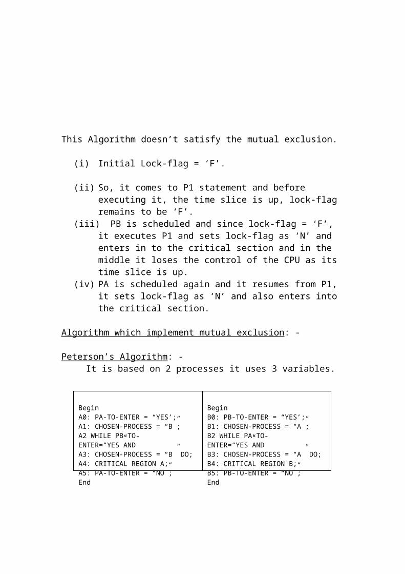
(6) At last, if everything is fine, the base (B) of that SMT entry is added to P which gives the indeed of the PMT.
(7) Now the page frame number is extracted from the selected PMT entry.
(8) The displacement is concatenated to this page frame number (F) to get the actual physical address.
Virtual Memory Management System: -
Introduction: -The main drawback of real memory management system is, if the
physical memory is limited, then the number of processes is can hold is also limited and thus limits the degree of multiprogramming. Also due to the swapping of the entire process, the efficiency is also decreased.
To overcome these drawbacks, virtual memory system is introduced. In this scheme the, process can start execution with only part of the process image in the memory.
Locality of Reference: -Sometimes over a short interval of time the addresses generated by a
typical program refer to a few localized areas of memory repeatedly, while the remainder of memory is accessed infrequently. This is said to be locality of reference. For example, when a loop is executed (or) every time a subroutine “is called the same set of instructions within the loop (or) within the subroutine are referred repeatedly. This loops and subroutines lead to localize the reference to memory for fetching instructions.
Page Fault: - Referring a page, which is outside the main memory [i.e. on the disk] is said to be page fault. In many systems, when a process is executing with only few pages in memory, and when an instruction is referred in some other page which is outside the main memory [i.e. on the disk] a page fault occurs. When this page fault occurs, before restarting the execution the OS must bring the required page into the memory. After some time, when a sufficient number of required pages build up, the pages will be found in the memory and thus reduces the page fault.