operating weight: engine: 120 kw / 161 hp stage tier 4f · engine: 120 kw / 161 hp stage tier 4f...
TRANSCRIPT

Wheeled ExcavatorA 918
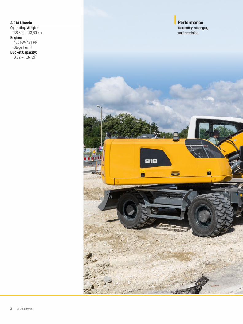
Operating Weight:38,800 – 43,600 lb
Engine:120 kW / 161 HP
Stage Tier 4f
Bucket Capacity:0.22 – 1.37 yd³
A 918 Litronic2
A 918 LitronicOperating Weight:
38,800 – 43,600 lbEngine:
120 kW / 161 HPStage Tier 4f
Bucket Capacity: 0.22 – 1.37 yd³
Performance Durability, strength, and precision

A 918 Litronic 3
Reliability
Competence, consistency,innovation – Proven experience
Comfort
Ergonomic excellence – Superior operators cab design for comfort and wellbeing
Economy
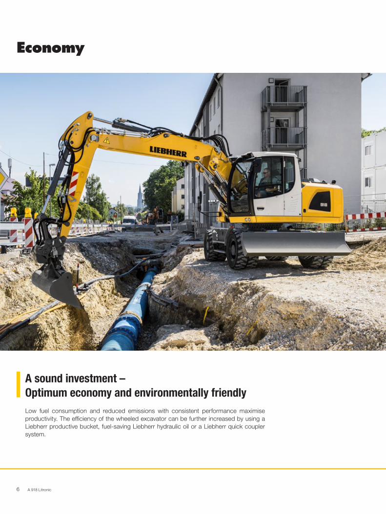
A sound investment – Optimum economy and environmentally friendly
Maintainability
Exceptional service and a reliable partnership

A 918 Litronic4
Durability, strength, and precisionEarthmoving, road construction, or sewer constructions are performed effortlessly every day by Liebherr wheeled excavators. Their constant power, speed, and precision make any job a success.
Performance

A 918 Litronic 5
High PerformanceThe superiorly engineered uppercarriage designs separates the mounting of the hoist cylinders. This allows the machine to have outstanding lift capacities close to the machine. The A 918 Litronic even exceeds the lift capacities of the next higher machine class which allows it to offer better performance in high demanding situations.
Working ModesThe working speed of the machine can easily be adjusted to any application by the use of the work MODE button. The Liebherr wheeled excavator is able to work at high speeds while still doing simultaneously movements. Excavation, backfilling and grading tasks can be completed quicker and on time.
Liebherr Tires Increased stability when working is provided by the twin tires without an intermediate ring and with offset cleats. The higher air pressure of the tires also ensures that there are fewer vibrations of the machine when driving. Higher traction on soft ground and low ground pressure are achieved with the larger contact surfaces of the Liebherr tires.
Working with PrecisionThe standard proportional controls joysticks coupled with the Liebherr hydraulic system enables the operators have more precise control of the excavators movements even at high speeds. This allows the operator can carry out any job faster, correct, and on time.
Automatic Digging BrakeThe automatic digging brake ensures that manual actuation of the brake pedal is no longer required, thus leading to easier operation of the machine. When the accelerator pedal is in a neutral position and the machine is stationary, the digging brake engages automatically. This results in faster work processes and enhanced safety for man and machine, particularly during operation with frequent relocation of the excavator. Furthermore, the automatic digging brake can be linked with the automatic swing axle lock. When the machine is deployed and working, the swing axle locks automatically and thereby provides optimum stability.
Travel Drive
• Higher traction for fast acceleration and the powerful engine allows for top speed up hills
• Reduces unproductive travel time between tasks and on the building site
• Faster on site – More productive
Digging Force
• High digging and breakout force in the field• Continuously high digging performance even
in tough ground• More digging force for faster results
Joystick Steering
• The optional joystick steering function enables the operator to steer the wheeled excavator using the mini-joystick
• Working and travelling movements can be done simultaneously with having to adjust your hands
• More efficient operation for greater productivity
Maximum Performance Precise Work
A 918 Litronic6
A sound investment –Optimum economy and environmentally friendlyLow fuel consumption and reduced emissions with consistent performance maximise productivity. The efficiency of the wheeled excavator can be further increased by using a Liebherr productive bucket, fuel-saving Liebherr hydraulic oil or a Liebherr quick coupler system.
Economy

A 918 Litronic 7
Maximum Efficiency Increased Productivity
Fuel Efficiency and Exhaust Gas AftertreatmentThe Liebherr D924 diesel engine helps to preserve the environ-ment and its resources with low fuel consumption and reduced emissions. For emission stage IV, Liebherr relies completely on an innovative SCR system from Liebherr, consisting of an SCR (Selective Catalytic Reductions) system and no other components such as a DPF (Diesel Particle Filter), DOC (Diesel Oxidation Catalyst), or EGR (Exhaust Gas Recirculation). This enables a 91 percent reduction of nitrogen oxide (NOX). The system reduces exhaust emissions without any compromise in performance.
Engine Idling and Engine Shut-downThe standard automatic idling function reduces the engine speed to idle as soon as the operator takes his hand from the joystick so that no hydraulic function is activated. Proximity sen-sors in the joystick levers restore the original engine speed as soon as the operator’s hand is moved towards the lever again. This ensures that the set engine speed is available immediately. The result is a combination of fuel saving and reduced noise levels. Operating costs can be reduced even further with the optional automatic engine shut-down function.
Liebherr Working Tools and LIKUFIXTo boost the productivity of its construction machines, Liebherr offers a broad range of working tools for different fields of ap-plication. Furthermore, the hydraulic excavators can also be equipped with the Liebherr LIKUFIX hydraulic quick coupling system. The combination of a hydraulic Liebherr quick cou-pling system with the LIKUFIX coupling block permits fast safe changing of mechanical and hydraulic working tools from the operators cab. This boosts productivity on average by 30 %.
Efficient ManagementLiDAT, Liebherr’s own data transmission and positioning sys-tem, facilitates efficient management, monitoring and control of machinery data recording, data analysis, fleet management and service. All of the important machinery data can be viewed at any time on a web browser. LiDAT provides you compre-hensive work deployment documentation, greater availability thanks to shorter downtimes, faster support from the manu-facturer, quicker detection of strain / overload and subsequently a longer service life of the machine as well as greater planning efficiency.
Low Fuel Consumption Thanks to Intelligent Machine Control
• Liebherr-Power Efficiency (LPE) optimises the interaction of the drive components in terms of efficiency
• LPE enables machine operation in the area of the lowest specific fuel use for less consumption and greater efficiency with the same performance
Liebherr Quick Coupling System LIKUFIX
• Faster and safer changing of mechanical and hydraulic working tools from the operator’s cabin
• Machine utilization increased to up to 90 % thanks to extended deployment options
• Visual and acoustic check of correct locking position of tool at quick coupling system by two proximity sensors
Low: Emissions and Operating Costs
• Innovative SCR system for compliance with emissions standard IV
• Lower emissions – Lower operating costs – Economic environmental protection
Engine speed [rpm]
Perfect operating point with LPE Operating point without LPE
OutputSpecific fuel consumption
Working range
Max
Min
LPE
Ou
tpu
t [k
W]
Sp
ecif
ic f
uel
co
nsu
mp
tio
n [g
/kW
h]
Max

A 918 Litronic8
Competence, consistency,innovation – Proven experienceReliability offers safety. Safety that significantly influences the success of a project. Whatever the weather, Liebherr stands for safety – with reliable construction machines and customer-oriented sales and service partners. This means a Liebherr construction machine is exactly what it should be: an investment that pays off.
Reliability

A 918 Litronic 9
Electronic Height LimitFor applications that have height restrictions because of obstructions in the overhead working area the wheeled excavator can be equipped with an electronic height limiter. The maximum permissible working height can be freely selected and stops the movement of the equipment when the set working height is reached. This helps avoid damage to the machine and its environment.
Pipe Fracture Safety ValvesThe standard pipe fracture safety valves on the stick and hoist cylinders prevent the attachments from falling uncontrollably and ensure maximum safety for personal working around the machine.
Quality and CompetenceOur experience and understanding of customers unique demands and our technical know-how guarantee the success of our product. Liebherr has decades of experience in the designing and manufacturing of equipment system solutions. Key components such as the diesel engine, electronic components, swing ring, swing drive and hydraulic cylinders are developed and produced by Liebherr. The great depth of in-house manufacturing guarantees maximum quality and ensures that components are optimally configured to each other.
Robust DesignAll steel components are designed and manufactured by Liebherr. High strength steel plates engineered for the toughest of requirements resulting in high torsional strength and optimal absorption of machine forces for longer machine service life.
Bright, Longlife Lighting
• The LED rear lights fitted as standard not only look good, but they are also brighter then halogen lighting and have an extremely long service life
• The LED front outline markers fitted as standard make it easier to see the machine on the road increasing worker safety
More Rear and Side Visibility
• The standard rear-view camera gives the operator optimal view of his working area and sorrounding machines at all times
• Extensive glazing in combination with two standard monitoring cameras ensure safe handling of the machine at all times
QPDM – Quality and Process Data Management
• QPDM allows production data to be logged, documented and evaluated
• Automation of documentation and test specifications
• Ability to handle large quantities and maintain uniform high quality
More Safety High Machine Quality

A 918 Litronic10
Ergonomic excellence – Superior operators cab design for comfort and wellbeingThe modern Liebherr operators cab with a standard air suspension heated drivers seat and automatic air-conditioning provides a pleasant working atmosphere allowing for the best work conditions for operators. The ergonomic control elements with touchscreen display also simplify the operation of the wheeled excavator. The extensive safety equipment includes the rollover protection system (ROPS) for the cab fitted as standard according to ISO 12117-2.
Comfort
A 918 Litronic 11
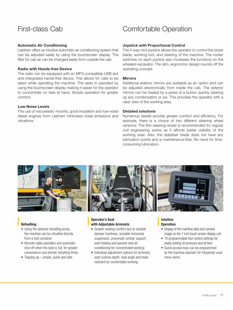
Automatic Air ConditioningLiebherr offers an intuitive automatic air conditioning system that can be adjusted easily by using the touchscreen display. The filter for cab air can be changed easily from outside the cab.
Radio with Hands-free DeviceThe radio can be equipped with an MP3-compatible USB slot and intergrated hands-free device. This allows for calls to be taken while operating the machine. The radio is operated by using the touchscreen display making it easier for the operator to concentrate on task at hand. Simple operation for greater comfort.
Low Noise LevelsThe use of viscoelastic mounts, good insulation and low-noise diesel engines from Liebherr minimises noise emissions and vibrations.
Joystick with Proportional Control The 4-way mini-joystick allows the operator to control the dozer blade, working tool, and steering of the machine. The rocker switches on each joystick also increases the functions on the wheeled excavator. The slim, ergonomic design rounds off the operating concept.
MirrorsAdditional exterior mirrors are available as an option and can be adjusted electronically from inside the cab. The exterior mirrors can be heated by a press of a button quickly clearing up any condensation or ice. This provides the operator with a clear view of the working area.
Detailed solutions Numerous details provide greater comfort and efficiency. For example, there is a choice of two different steering wheel versions: The thin steering wheel is recommended for regular civil engineering works as it affords better visibility of the working area. Also, the stabiliser blade does not have any lubrication points and is maintenance-free. No need for time-consuming lubrication.
Refuelling
• Using the optional refuelling pump, the machine can be refuelled directly from a fuel container
• Remote cable operation and automatic shut off when the tank is full, for greater convenience and shorter refuelling times
• Topping up – simple, quick and safe
Operator’s Seat with Adjustable Armrests
• Greater seating comfort due to variable damper hardness, lockable horizontal suspension, pneumatic lumbar support, seat heating and passive seat air conditioning for concentrated working
• Individual adjustment options for armrests, seat cushion depth, seat angle and head restraint for comfortable working
Intuitive Operation
• Display of the machine data and camera image on the 7 inch touch screen display unit
• 10 programmable tool control settings for easily setting oil pressure and oil flow
• Quick access keys can be programmed by the machine operator for frequently used menu items
First-class Cab Comfortable Operation

A 918 Litronic12
Exceptional service and a reliable partnershipLiebherr wheeled excavators are not only powerful, robust, precise and efficient, they are also designed with machine service principle in mind. Maintenance is performed quickly, simply and safely. This reduces maintenance costs and keeps machine downtimes to a minimum.
Maintainability
A 918 Litronic 13
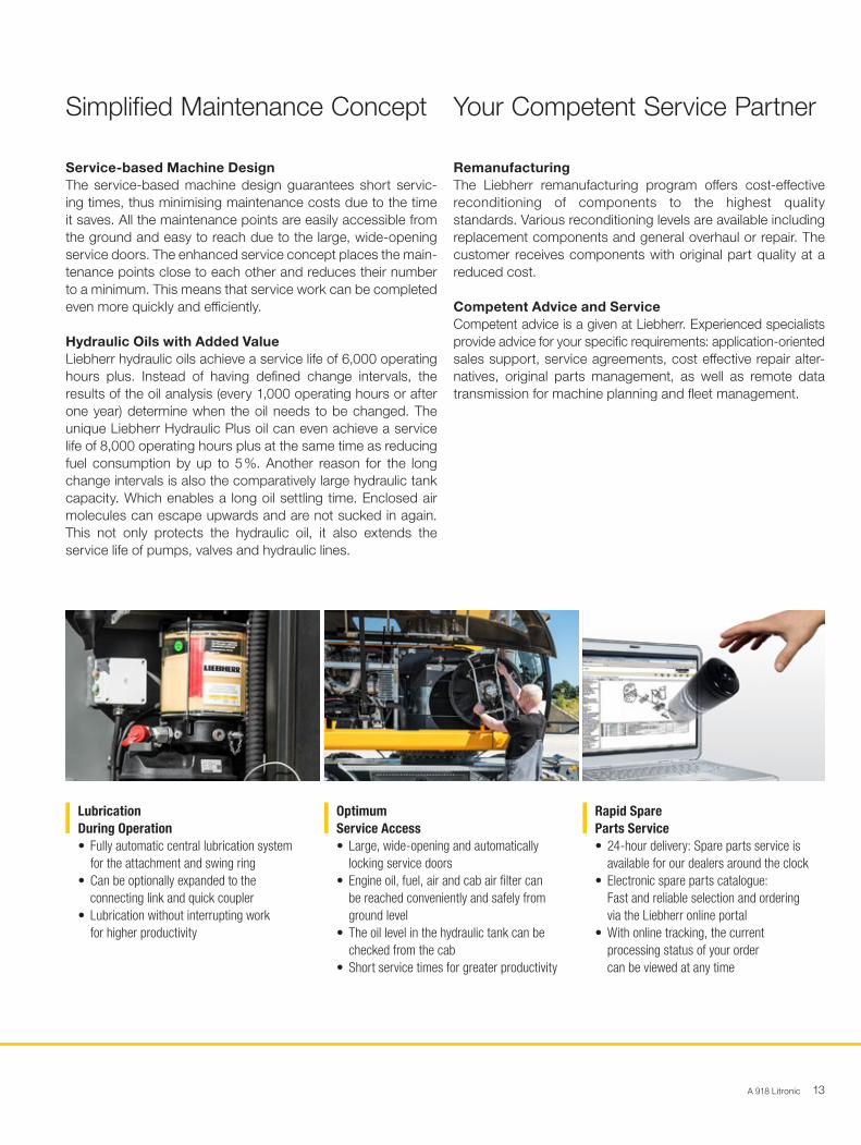
Service-based Machine DesignThe service-based machine design guarantees short servic-ing times, thus minimising maintenance costs due to the time it saves. All the maintenance points are easily accessible from the ground and easy to reach due to the large, wide-opening service doors. The enhanced service concept places the main-tenance points close to each other and reduces their number to a minimum. This means that service work can be completed even more quickly and efficiently.
Hydraulic Oils with Added ValueLiebherr hydraulic oils achieve a service life of 6,000 operating hours plus. Instead of having defined change intervals, the results of the oil analysis (every 1,000 operating hours or after one year) determine when the oil needs to be changed. The unique Liebherr Hydraulic Plus oil can even achieve a service life of 8,000 operating hours plus at the same time as reducing fuel consumption by up to 5 %. Another reason for the long change intervals is also the comparatively large hydraulic tank capacity. Which enables a long oil settling time. Enclosed air molecules can escape upwards and are not sucked in again. This not only protects the hydraulic oil, it also extends the service life of pumps, valves and hydraulic lines.
RemanufacturingThe Liebherr remanufacturing program offers cost-effective reconditioning of components to the highest quality standards. Various reconditioning levels are available including replacement components and general overhaul or repair. The customer receives components with original part quality at a reduced cost.
Competent Advice and ServiceCompetent advice is a given at Liebherr. Experienced specialists provide advice for your specific requirements: application-oriented sales support, service agreements, cost effective repair alter-natives, original parts management, as well as remote data transmission for machine planning and fleet management.
Lubrication During Operation
• Fully automatic central lubrication system for the attachment and swing ring
• Can be optionally expanded to the connecting link and quick coupler
• Lubrication without interrupting work for higher productivity
Optimum Service Access
• Large, wide-opening and automatically locking service doors
• Engine oil, fuel, air and cab air filter can be reached conveniently and safely from ground level
• The oil level in the hydraulic tank can be checked from the cab
• Short service times for greater productivity
Rapid Spare Parts Service
• 24-hour delivery: Spare parts service is available for our dealers around the clock
• Electronic spare parts catalogue: Fast and reliable selection and ordering via the Liebherr online portal
• With online tracking, the current processing status of your order can be viewed at any time
Simplified Maintenance Concept Your Competent Service Partner
A 918 Litronic14
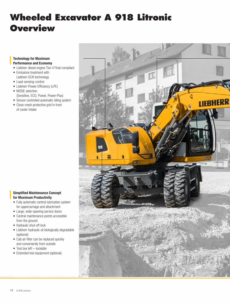
Wheeled Excavator A 918 LitronicOverview
Technology for Maximum Performance and Economy
• Liebherr diesel engine Tier 4 Final compliant• Emissions treatment with
Liebherr-SCR technology• Load-sensing-control• Liebherr-Power-Efficiency (LPE) • MODE selection
(Sensitive, ECO, Power, Power-Plus) • Sensor-controlled automatic idling system • Close-mesh protective grid in front
of cooler intake
Simplified Maintenance Concept for Maximum Productivity
• Fully automatic central lubrication system for uppercarriage and attachment
• Large, wide-opening service doors• Central maintenance points accessible
from the ground• Hydraulic shut-off lock• Liebherr hydraulic oil biologically degradable
(optional)• Cab air filter can be replaced quickly
and conveniently from outside• Tool box left – lockable• Extended tool equipment (optional)

A 918 Litronic 15
Ergonomic Operators Cab for Maximum Comfort
• Operator’s seat Comfort / Premium (optional)• Automatic air-conditioning system • 7" color touchscreen display• Direct access keys • Adjustable armrests • Resonant, ergonomic joysticks • Joystick steering (optional)• Proportional control with 4-way mini-joystick • Large windows • Convenient radio operation with
hands-free device • Tool Control for working tools • Front guard, adjustable (optional) • LED lights (optional) • Rear and side camera monitoring
Superbly Designed Equipment for Maximum Reliability
• Various boom versions and stick lengths• Liebherr hydraulic cylinders• Pipe fracture safety valves hoisting
and stick cylinders• Overload warning device• Load holding valve on stabilization cylinder • Electronic lift limitation (optional)• Liebherr quick coupling systems (optional) • Wide selection of Liebherr working tools
(optional)
16 A 918 Litronic
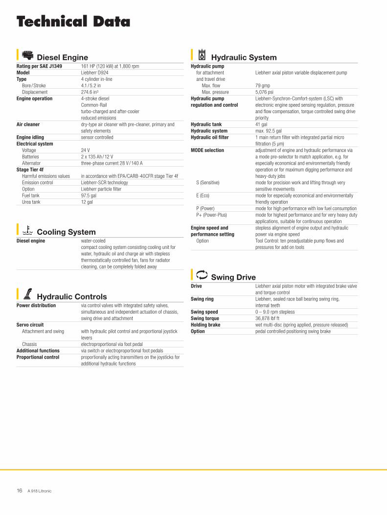
Technical Data
Swing DriveDrive Liebherr axial piston motor with integrated brake valve
and torque controlSwing ring Liebherr, sealed race ball bearing swing ring,
internal teethSwing speed 0 – 9.0 rpm steplessSwing torque 36,878 lbf ftHolding brake wet multi-disc (spring applied, pressure released)Option pedal controlled positioning swing brake
Hydraulic SystemHydraulic pump
for attachment and travel drive
Liebherr axial piston variable displacement pump
Max. flow 79 gmpMax. pressure 5,076 psi
Hydraulic pump regulation and control
Liebherr-Synchron-Comfort-system (LSC) with electronic engine speed sensing regulation, pressure and flow compensation, torque controlled swing drive priority
Hydraulic tank 41 galHydraulic system max. 92.5 galHydraulic oil filter 1 main return filter with integrated partial micro
filtration (5 µm)MODE selection adjustment of engine and hydraulic performance via
a mode pre-selector to match application, e.g. for especially economical and environmentally friendly operation or for maximum digging performance and heavy-duty jobs
S (Sensitive) mode for precision work and lifting through very sensitive movements
E (Eco) mode for especially economical and environmentally friendly operation
P (Power) mode for high performance with low fuel consumptionP+ (Power-Plus) mode for highest performance and for very heavy duty
applications, suitable for continuous operationEngine speed and performance setting
stepless alignment of engine output and hydraulic power via engine speed
Option Tool Control: ten preadjustable pump flows and pressures for add on tools
Diesel EngineRating per SAE J1349 161 HP (120 kW) at 1,800 rpmModel Liebherr D924Type 4 cylinder in-line
Bore / Stroke 4.1 / 5.2 inDisplacement 274.6 in3
Engine operation 4-stroke diesel Common-Rail turbo-charged and after-cooler reduced emissions
Air cleaner dry-type air cleaner with pre-cleaner, primary and safety elements
Engine idling sensor controlledElectrical system
Voltage 24 VBatteries 2 x 135 Ah / 12 VAlternator three-phase current 28 V / 140 A
Stage Tier 4fHarmful emissions values in accordance with EPA/CARB-40CFR stage Tier 4fEmission control Liebherr-SCR technologyOption Liebherr particle filterFuel tank 97.5 galUrea tank 12 gal
Hydraulic ControlsPower distribution via control valves with integrated safety valves,
simultaneous and independent actuation of chassis, swing drive and attachment
Servo circuitAttachment and swing with hydraulic pilot control and proportional joystick
leversChassis electroproportional via foot pedal
Additional functions via switch or electroproportional foot pedalsProportional control proportionally acting transmitters on the joysticks for
additional hydraulic functions
Cooling SystemDiesel engine water-cooled
compact cooling system consisting cooling unit for water, hydraulic oil and charge air with stepless thermostatically controlled fan, fans for radiator cleaning, can be completely folded away

A 918 Litronic 17
Operator’s CabCab ROPS safety cab structure (roll-over protection system)
with individual windscreens or featuring a slide-in subpart under the ceiling, work headlights integrated in the ceiling, a door with a sliding window (can be opened on both sides), large stowing and depositing possibilities, shock-absorbing suspension, sound-damping insulating, tinted laminated safety glass, separate window shades for the sunroof window and windscreen
Operator’s seat Standard air cushioned operator’s seat with 3D-adjustable arm-rests, headrest, lap belt, seat heater, manual weight adjustment, adjustable seat cushion inclination and length and mechanical lumbar vertebrae support
Operator’s seat Comfort (Option)
in addition to operator’s seat standard: lockable hori-zontal suspension, automatic weight adjustment, adjustable suspension stiffness, pneumatic lumbar vertebrae support and passive seat climatisation with active coal
Operator’s seat Premium (Option)
in addition to operator’s seat comfort: active electronic weight adjustment (automatic readjustment), pneu-matic low frequency suspension and active seat clima-tisation with active coal and ventilator
Control system joysticks with arm consoles and swivel seat, folding left arm console
Operation and displays large high-resolution operating unit, selfexplanatory, color display with touchscreen, video-compatible, numerous setting, control and monitoring options, e.g. air conditioning control, fuel consumption, machine and tool parameters
Air-conditioning automatic air-conditioning, recirculated air function, fast de-icing and demisting at the press of a button, air vents can be operated via a menu; recirculated air and fresh air filters can be easily replaced and are accessible from the outside; heating-cooling unit, designed for extreme outside temperatures, sensors for solar radiation, inside and outside temperatures (country-dependent)
UndercarriageDrive oversized two speed power shift transmission with
additional creeper speed, Liebherr axial piston motor with functional brake valve on both sides
Pulling force 26,303 lbfTravel speed 0 – 2.2 mph stepless (creeper speed off-road)
0 – 4.3 mph stepless (off-road) 0 – 8.1 mph stepless (creeper speed on-road) 0 – 12.4 mph stepless (road travel) 0 – max. 15.5 or 18.6 mph Speeder (Option)
Driving operation automotive driving using accelerator pedal, cruise control function: storage of variable accelerator pedal positions, both off-road and on-road
Axles manual or automatic hydraulically controlled front axle oscillation lock
Service brake two circuit travel brake system with accumulator; wet and backlash-free disc brake
Automatic digging brake works automatically when driving off (accelerator pedal actuation) and when the machine is stationary (engage-ment); the digging brake engages automatically – can be coupled with automatic swing axle lock
Holding brake wet multi-disc (spring applied, pressure released)Stabilization stabilizing blade (adjustable during travel for dozing)
stabilizing blade rear stabilizing blade front + 2 point outriggers rear 4 point outriggers
Option EW-undercarriage 9'
AttachmentType high-strength steel plates at highlystressed points
for the toughest requirements. Complex and stable mountings of attachment and cylinders
Hydraulic cylinders Liebherr cylinders with special seal system as well as shock absorption
Bearings sealed, low maintenance
Complete MachineLubrication Liebherr central lubrication system for uppercarriage
and attachment, automaticallyNoise emission
ISO 6396 LpA (inside cab) = 71 dB(A)2000/14/EC LWA (surround noise) = 101 dB(A)
18 A 918 Litronic
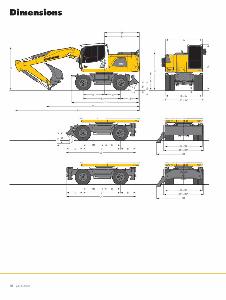
Dimensions
918
D
E
V
W
T2
U2
L
M1 M
X
Q
C
B = B2
B* = B2*
A
H
J2I2
K
H1020
918
J3 I3
M1 M B = B2
H1027
B* = B2*
B1
T1T3 L
U3
918
M1 M B = B2
H1028
B1
T1T4 L
U4B* = B2*

A 918 Litronic 19
ft inA 8' 3"B 8' 4"B* 9' B1 12' 1"B2 8' 4"B2* 9' C 10' 5"D 7'10"E 7'10"H 8' 6"I2 1' 5"I3 1' 3"J2 2' J3 1'11"K 4' L 8' 4"M 3' 7"M1 4' 9"Q 1' 2"T1 3' 5"T2 4' T3 3' 9"T4 3' 7"U2 15' U3 15' 7"U4 15' 4"
* EW-UndercarriageE = Tail radiusTires 10.00-20
Stick Two-piece boom 17'3" Mono boom 16'5" ft in
Stabilizer blade ft in
Blade + 2 pt. outriggers ft in
4 pt. outriggers ft in
Stabilizer blade ft in
Blade + 2 pt. outriggers ft in
4 pt. outriggers ft in
V 7'5" 20'10" 20'10" 20'10" 19' 19' 19'8"*8' 19' 8" 19' 8" 19' 8" 18' 1" 18' 1" 18'8"*8'8" 19' 4" 19' 4" 19' 4" 17' 3" 18' 1"* 18'1"*
W 7'5" 10' 10' 10' 10' 4" 10' 4" 10'4"*8' 10' 10' 10' 10' 4" 10' 4" 10'4"*8'8" 10' 2" 10' 2" 10' 2" 10' 4" 10' 4"* 10'4"*
X 7'5" 28' 8" 28' 8" 28' 8" 27'11" 27'11" 28'8"*8' 28' 8" 28' 8" 28' 8" 27'11" 27'11" 28'8"*8'8" 28' 8" 28' 8" 28' 8" 28' 1" 28' 8"* 28'8"*
Stick Offset two-piece boom 16'5" ft in
Stabilizer blade ft in
Blade + 2 pt. outriggers ft in
4 pt. outriggers ft in
V 7'5" 21' 2" 21' 2" 21' 2"8' 19'10" 19'10" 19'10"8'8" 19' 19' 19'
W 7'5" 10' 6" 10' 6" 10' 6"8' 10' 6" 10' 6" 10' 6"8'8" 10' 6" 10' 6" 10' 6"
X 7'5" 28' 1" 28' 1" 28' 1"8' 28' 1" 28' 1" 28' 1"8'8" 28' 1" 28' 1" 28' 1"
Dimensions are with attachment over steering axle* Attachment over digging axle for shorter transport dimensions

20 A 918 Litronic
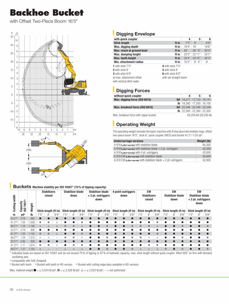
Backhoe Bucketwith Two-Piece Boom 17'3"
Operating WeightThe operating weight includes the basic machine with 8 tires plus intermediate rings, two-piece boom 17'3", stick 8', quick coupler SW33 and bucket 41.3" / 1.05 yd3.
Undercarriage versions Weight (lb)A 918 litronic̀ with stabilizer blade 39,000A 918 litronic̀ with stabilizer blade + 2 pt. outriggers 41,000A 918 litronic̀ with 4 pt. outriggers 41,400A 918 EW litronic̀ with stabilizer blade 39,200A 918 EW litronic̀ with stabilizer blade + 2 pt. outriggers 41,200
Buckets Machine stability per ISO 10567* (75 % of tipping capacity)
Cutt
ing
wid
th
Capa
city
IS
O 74
511)
Wei
ght
Stabilizers raised
Stick length (ft in)
Stabilizer blade down
Stick length (ft in)
Stabilizer blade + 2 pt. outriggers
down
Stick length (ft in)
4 point outriggers down
Stick length (ft in)
EW Stabilizers
raised
Stick length (ft in)
EW Stabilizer blade
down
Stick length (ft in)
EW Stabilizer blade
+ 2 pt. outriggers down
Stick length (ft in)
in yd3 lb 7'5" 8' 8'8" 7'5" 8' 8'8" 7'5" 8' 8'8" 7'5" 8' 8'8" 7'5" 8' 8'8" 7'5" 8' 8'8" 7'5" 8' 8'8"19.7"2) 0.39 639 y y y y y y y y y y y y y y y y y y y y y
25.6"2) 0.55 772 y y y y y y y y y y y y y y y y y y y y y
33.5"2) 0.78 882 y y y y y y y y y y y y y y y y y y y y y
41.3"2) 1.05 1,058 y y y y y y y y y y y y y y y y y y y y y
49.2"2) 1.24 1,168 V V V y y y y y y y y y y y y y y y y y y
19.7"3) 0.39 683 y y y y y y y y y y y y y y y y y y y y y
25.6"3) 0.55 794 y y y y y y y y y y y y y y y y y y y y y
33.5"3) 0.78 926 y y y y y y y y y y y y y y y y y y y y y
41.3"3) 1.05 1,102 y y y y y y y y y y y y y y y y y y y y y
49.2"3) 1.24 1,213 V V V y y y y y y y y y y y y y y y y y y
19.7"4) 0.42 617 y y y y y y y y y y y y y y y y y y y y y
25.6"4) 0.59 728 y y y y y y y y y y y y y y y y y y y y y
33.5"4) 0.85 838 y y y y y y y y y y y y y y y y y y y y y
41.3"4) 1.11 1,014 y y y y y y y y y y y y y y y y y y y y y
49.2"4) 1.37 1,102 V V V y V V y y y y y y y V V y y y y y y
* Indicated loads are based on ISO 10567 and do not exceed 75 % of tipping or 87 % of hydraulic capacity, max. stick length without quick coupler, lifted 360° on firm with blocked oscillating axle
1) comparable with SAE (heaped)2) Bucket with teeth 3) Bucket with teeth in HD-version 4) Bucket with cutting edge (also available in HD-version)Buckets with 19.7" cutting width with limited digging depth
Max. material weight y = ≤ 3,034 lb/yd3, y = ≤ 2,528 lb/yd3, V = ≤ 2,023 lb/yd3, – = not authorized
Digging Envelopewith quick coupler 1 2 3Stick length ft in 7'5" 8' 8' 8"Max. digging depth ft in 18'6" 19'2" 19'10"Max. reach at ground level ft in 30' 30'6" 31' 2"Max. dumping height ft in 23'5" 24'1" 24' 7"Max. teeth height ft in 33'8" 34'3" 34' 9"Min. attachment radius ft in 9'4" 9'2" 9' 4"
Digging Forceswithout quick coupler 1 2 3Max. digging force (ISO 6015) lbf 18,277 17,153 16,141
lb 18,300 17,200 16,100Max. breakout force (ISO 6015) lbf 22,346 22,346 22,346
lb 22,300 22,300 22,300Max. breakout force with ripper bucket 28,259 lbf (28,200 lb)
918
25
30
35
20
15
10
5
-5
-10
-15
-20
0
9
10
8
11
12 3
H1023
30 25 20 15 10 5
10 8 6 4 2 13579
7
6
5
4
3
2
1
0
-1
-2
-3
-4
-5
-7
-6
0
0
m
ft
mft

A 918 Litronic 21
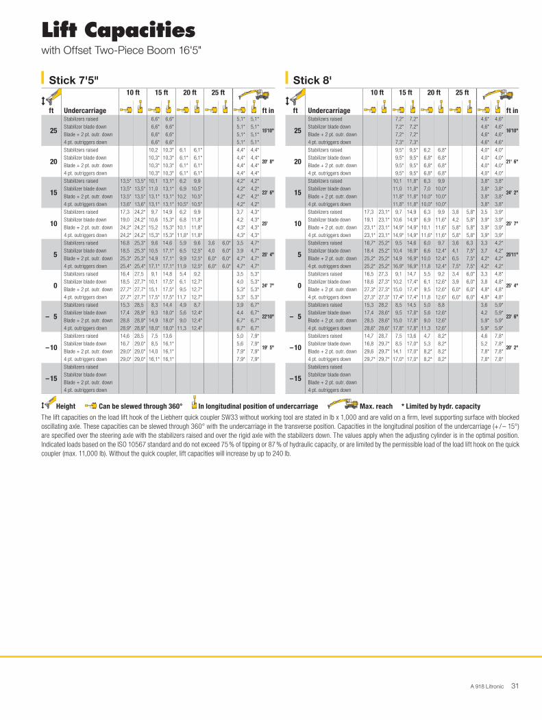
Stick 7'5" ft
Undercarriage
10 ft 15 ft 20 ft 25 ft
ft in
25
Stabilizers raised 8,5* 8,5* 5,4* 5,4*
17' 1"Stabilizer blade down 8,5* 8,5* 5,4* 5,4*Blade + 2 pt. outr. down 8,5* 8,5* 5,4* 5,4*4 pt. outriggers down 8,5* 8,5* 5,4* 5,4*
20
Stabilizers raised 10,4 10,6* 6,4 8,0* 4,8* 4,8*
21' 8"Stabilizer blade down 10,6* 10,6* 7,1 8,0* 4,8* 4,8*Blade + 2 pt. outr. down 10,6* 10,6* 8,0* 8,0* 4,8* 4,8*4 pt. outriggers down 10,6* 10,6* 8,1* 8,1* 4,8* 4,8*
15
Stabilizers raised 14,6* 14,6* 10,1 13,7* 6,5 10,2 4,4 4,6*
24' 5"Stabilizer blade down 14,6* 14,6* 11,1 13,7* 7,2 11,4* 4,6* 4,6*Blade + 2 pt. outr. down 14,6* 14,6* 13,7* 13,7* 10,5 11,4* 4,6* 4,6*4 pt. outriggers down 14,6* 14,6* 13,7* 13,7* 11,4* 11,4* 4,6* 4,6*
10
Stabilizers raised 17,5 25,4* 9,8 15,2 6,5 10,1 4,2 6,9 3,9 4,7*
25'10"Stabilizer blade down 19,2 25,4* 10,8 16,1* 7,1 12,3* 4,6 7,3* 4,3 4,7*Blade + 2 pt. outr. down 25,4* 25,4* 15,5 16,1* 10,3 12,3* 7,1 7,3* 4,7* 4,7*4 pt. outriggers down 25,4* 25,4* 16,1* 16,1* 12,3 12,3* 7,3* 7,3* 4,7* 4,7*
5
Stabilizers raised 17,1 25,0* 9,7 15,0 6,3 10,0 4,0 6,7 3,7 5,0*
26' 1"Stabilizer blade down 18,9 25,1* 10,6 18,0* 6,9 13,1* 4,5 9,3* 4,1 5,0*Blade + 2 pt. outr. down 25,0* 25,1* 15,3 18,0* 10,2 13,1* 6,9 9,3* 5,0* 5,0*4 pt. outriggers down 25,1* 25,1* 18,0* 18,0* 12,2 13,1* 8,5 9,3* 5,0* 5,0*
0
Stabilizers raised 16,6 28,1* 9,3 15,1 5,9 9,6 3,9 6,6 3,7 5,7*
25' 5"Stabilizer blade down 18,7 28,1* 10,3 18,4* 6,5 13,3* 4,3 8,0* 4,2 5,7*Blade + 2 pt. outr. down 28,1* 28,1* 15,4 18,4* 9,9 13,3* 6,8 8,0* 5,7* 5,7*4 pt. outriggers down 28,1* 28,1* 18,3 18,4* 12,1 13,3* 8,0* 8,0* 5,7* 5,7*
– 5
Stabilizers raised 15,8 29,1 8,9 14,9 5,5 9,2 4,1 7,0*
23' 8"Stabilizer blade down 17,9 29,9* 9,9 18,7* 6,1 13,4* 4,6 7,0*Blade + 2 pt. outr. down 29,7 29,9* 15,4 18,7* 9,5 13,4* 7,0* 7,0*4 pt. outriggers down 29,9* 29,9* 18,6 18,7* 11,8 13,4* 7,0* 7,0*
– 10
Stabilizers raised 15,5 29,3 8,2 14,2 5,3 9,0 5,1 8,1*
20' 6"Stabilizer blade down 17,5 30,7* 9,2 17,8* 5,9 9,0* 5,7 8,1*Blade + 2 pt. outr. down 30,3 30,7* 14,6 17,8* 9,0* 9,0* 8,1* 8,1*4 pt. outriggers down 30,7* 30,7* 17,8* 17,8* 9,0* 9,0* 8,1* 8,1*
– 15
Stabilizers raisedStabilizer blade downBlade + 2 pt. outr. down4 pt. outriggers down
Stick 8' ft
Undercarriage
10 ft 15 ft 20 ft 25 ft
ft in
25
Stabilizers raised 8,4* 8,4* 4,9* 4,9*
18' 1"Stabilizer blade down 8,4* 8,4* 4,9* 4,9*Blade + 2 pt. outr. down 8,4* 8,4* 4,9* 4,9*4 pt. outriggers down 8,4* 8,4* 4,9* 4,9*
20
Stabilizers raised 9,7* 9,7* 6,5 8,1* 4,3* 4,3*
22' 6"Stabilizer blade down 9,7* 9,7* 7,1 8,1* 4,3* 4,3*Blade + 2 pt. outr. down 9,7* 9,7* 8,1* 8,1* 4,3* 4,3*4 pt. outriggers down 9,7* 9,7* 8,1* 8,1* 4,3* 4,3*
15
Stabilizers raised 10,1 12,2* 6,6 10,2 4,2 4,4* 4,2* 4,2*
25' 1"Stabilizer blade down 11,1 12,2* 7,2 10,7* 4,4* 4,4* 4,2* 4,2*Blade + 2 pt. outr. down 12,2* 12,2* 10,4 10,7* 4,4* 4,4* 4,2* 4,2*4 pt. outriggers down 12,2* 12,2* 10,7* 10,7* 4,4* 4,4* 4,2* 4,2*
10
Stabilizers raised 17,5 25,0* 9,8 15,2 6,5 10,0 4,2 6,9 3,7 4,2*
26' 5"Stabilizer blade down 19,3 25,0* 10,7 15,7* 7,2 12,1* 4,7 8,0* 4,1 4,2*Blade + 2 pt. outr. down 25,0* 25,0* 15,5 15,7* 10,3 12,1* 7,1 8,0* 4,2* 4,2*4 pt. outriggers down 25,0* 25,0* 15,7* 15,7* 12,1* 12,1* 8,1* 8,1* 4,2* 4,2*
5
Stabilizers raised 17,0 24,8* 9,6 14,9 6,3 10,0 4,1 6,7 3,5 4,5*
26'10"Stabilizer blade down 18,8 24,8* 10,6 17,8* 7,0 13,0* 4,5 9,9 3,9 4,5*Blade + 2 pt. outr. down 24,8* 24,8* 15,2 17,8* 10,2 13,0* 6,9 10,0* 4,5* 4,5*4 pt. outriggers down 24,8* 24,8* 17,8* 17,8* 12,1 13,0* 8,5 10,0* 4,5* 4,5*
0
Stabilizers raised 16,7 27,5* 9,3 15,0 5,9 9,6 3,9 6,6 3,5 5,1*
26' 1"Stabilizer blade down 18,8 27,5* 10,3 18,3* 6,6 13,2* 4,3 9,8 4,0 5,1*Blade + 2 pt. outr. down 27,5* 27,5* 15,3 18,3* 9,9 13,2* 6,8 9,8* 5,1* 5,1*4 pt. outriggers down 27,5* 27,5* 18,2 18,3* 12,2 13,2* 8,3 9,8* 5,1* 5,1*
– 5
Stabilizers raised 15,8 28,9 8,8 15,0 5,5 9,2 3,9 6,2*
24' 5"Stabilizer blade down 17,8 29,7* 9,8 18,5* 6,1 13,4* 4,4 6,2*Blade + 2 pt. outr. down 29,4 29,7* 15,4 18,5* 9,5 13,4* 6,2* 6,2*4 pt. outriggers down 29,7* 29,7* 18,5 18,5* 11,8 13,4* 6,2* 6,2*
– 10
Stabilizers raised 15,6 29,5 8,2 14,2 5,2 9,0 4,7 8,0*
21' 4"Stabilizer blade down 17,6 30,8* 9,2 18,4* 5,9 10,3* 5,3 8,0*Blade + 2 pt. outr. down 30,4 30,8* 14,6 18,4* 9,2 10,3* 8,0* 8,0*4 pt. outriggers down 30,8* 30,8* 18,4* 18,4* 10,3* 10,3* 8,0* 8,0*
– 15
Stabilizers raised 15,0 18,7* 14,9 18,6*
10' Stabilizer blade down 17,0 18,7* 16,9 18,6*Blade + 2 pt. outr. down 18,7* 18,7* 18,6* 18,6*4 pt. outriggers down 18,8* 18,8*
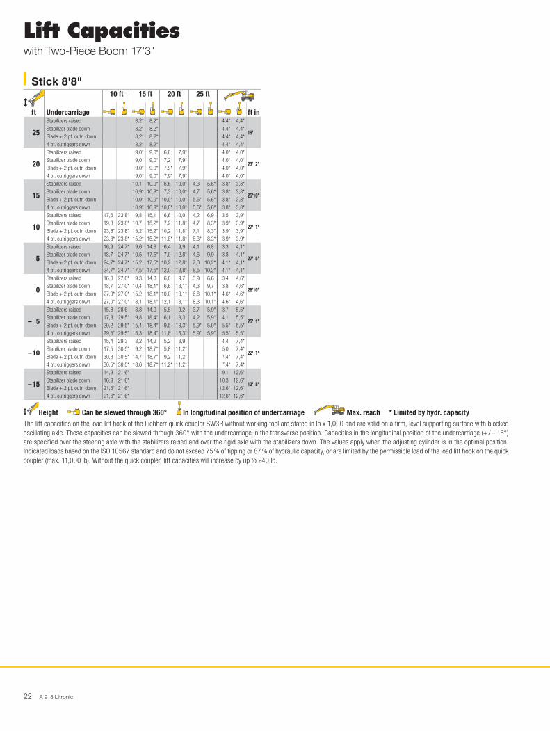
Lift Capacitieswith Two-Piece Boom 17'3"
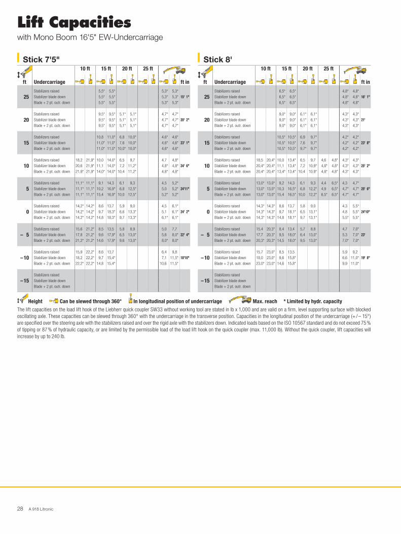
Height Can be slewed through 360° In longitudinal position of undercarriage Max. reach * Limited by hydr. capacityThe lift capacities on the load lift hook of the Liebherr quick coupler SW33 without working tool are stated in lb x 1,000 and are valid on a firm, level supporting surface with blocked oscillating axle. These capacities can be slewed through 360° with the undercarriage in the transverse position. Capacities in the longitudinal position of the undercarriage (+ / – 15°) are specified over the steering axle with the stabilizers raised and over the rigid axle with the stabilizers down. The values apply when the adjusting cylinder is in the optimal position. Indicated loads based on the ISO 10567 standard and do not exceed 75 % of tipping or 87 % of hydraulic capacity, or are limited by the permissible load of the load lift hook on the quick coupler (max. 11,000 lb). Without the quick coupler, lift capacities will increase by up to 240 lb.
22 A 918 Litronic
Stick 8'8" ft
Undercarriage
10 ft 15 ft 20 ft 25 ft
ft in
25
Stabilizers raised 8,2* 8,2* 4,4* 4,4*
19' Stabilizer blade down 8,2* 8,2* 4,4* 4,4*Blade + 2 pt. outr. down 8,2* 8,2* 4,4* 4,4*4 pt. outriggers down 8,2* 8,2* 4,4* 4,4*
20
Stabilizers raised 9,0* 9,0* 6,6 7,9* 4,0* 4,0*
23' 2"Stabilizer blade down 9,0* 9,0* 7,2 7,9* 4,0* 4,0*Blade + 2 pt. outr. down 9,0* 9,0* 7,9* 7,9* 4,0* 4,0*4 pt. outriggers down 9,0* 9,0* 7,9* 7,9* 4,0* 4,0*
15
Stabilizers raised 10,1 10,9* 6,6 10,0* 4,3 5,6* 3,8* 3,8*
25'10"Stabilizer blade down 10,9* 10,9* 7,3 10,0* 4,7 5,6* 3,8* 3,8*Blade + 2 pt. outr. down 10,9* 10,9* 10,0* 10,0* 5,6* 5,6* 3,8* 3,8*4 pt. outriggers down 10,9* 10,9* 10,0* 10,0* 5,6* 5,6* 3,8* 3,8*
10
Stabilizers raised 17,5 23,8* 9,8 15,1 6,6 10,0 4,2 6,9 3,5 3,9*
27' 1"Stabilizer blade down 19,3 23,8* 10,7 15,2* 7,2 11,8* 4,7 8,3* 3,9* 3,9*Blade + 2 pt. outr. down 23,8* 23,8* 15,2* 15,2* 10,2 11,8* 7,1 8,3* 3,9* 3,9*4 pt. outriggers down 23,8* 23,8* 15,2* 15,2* 11,8* 11,8* 8,3* 8,3* 3,9* 3,9*
5
Stabilizers raised 16,9 24,7* 9,6 14,8 6,4 9,9 4,1 6,8 3,3 4,1*
27' 5"Stabilizer blade down 18,7 24,7* 10,5 17,5* 7,0 12,8* 4,6 9,9 3,8 4,1*Blade + 2 pt. outr. down 24,7* 24,7* 15,2 17,5* 10,2 12,8* 7,0 10,2* 4,1* 4,1*4 pt. outriggers down 24,7* 24,7* 17,5* 17,5* 12,0 12,8* 8,5 10,2* 4,1* 4,1*
0
Stabilizers raised 16,8 27,0* 9,3 14,8 6,0 9,7 3,9 6,6 3,4 4,6*
26'10"Stabilizer blade down 18,7 27,0* 10,4 18,1* 6,6 13,1* 4,3 9,7 3,8 4,6*Blade + 2 pt. outr. down 27,0* 27,0* 15,2 18,1* 10,0 13,1* 6,8 10,1* 4,6* 4,6*4 pt. outriggers down 27,0* 27,0* 18,1 18,1* 12,1 13,1* 8,3 10,1* 4,6* 4,6*
– 5
Stabilizers raised 15,8 28,6 8,8 14,9 5,5 9,2 3,7 5,9* 3,7 5,5*
25' 1"Stabilizer blade down 17,8 29,5* 9,8 18,4* 6,1 13,3* 4,2 5,9* 4,1 5,5*Blade + 2 pt. outr. down 29,2 29,5* 15,4 18,4* 9,5 13,3* 5,9* 5,9* 5,5* 5,5*4 pt. outriggers down 29,5* 29,5* 18,3 18,4* 11,8 13,3* 5,9* 5,9* 5,5* 5,5*
– 10
Stabilizers raised 15,4 29,3 8,2 14,2 5,2 8,9 4,4 7,4*
22' 1"Stabilizer blade down 17,5 30,5* 9,2 18,7* 5,8 11,2* 5,0 7,4*Blade + 2 pt. outr. down 30,3 30,5* 14,7 18,7* 9,2 11,2* 7,4* 7,4*4 pt. outriggers down 30,5* 30,5* 18,6 18,7* 11,2* 11,2* 7,4* 7,4*
– 15
Stabilizers raised 14,9 21,6* 9,1 12,6*
13' 8"Stabilizer blade down 16,9 21,6* 10,3 12,6*Blade + 2 pt. outr. down 21,6* 21,6* 12,6* 12,6*4 pt. outriggers down 21,6* 21,6* 12,6* 12,6*
Lift Capacitieswith Two-Piece Boom 17'3"
Height Can be slewed through 360° In longitudinal position of undercarriage Max. reach * Limited by hydr. capacityThe lift capacities on the load lift hook of the Liebherr quick coupler SW33 without working tool are stated in lb x 1,000 and are valid on a firm, level supporting surface with blocked oscillating axle. These capacities can be slewed through 360° with the undercarriage in the transverse position. Capacities in the longitudinal position of the undercarriage (+ / – 15°) are specified over the steering axle with the stabilizers raised and over the rigid axle with the stabilizers down. The values apply when the adjusting cylinder is in the optimal position. Indicated loads based on the ISO 10567 standard and do not exceed 75 % of tipping or 87 % of hydraulic capacity, or are limited by the permissible load of the load lift hook on the quick coupler (max. 11,000 lb). Without the quick coupler, lift capacities will increase by up to 240 lb.
A 918 Litronic 23
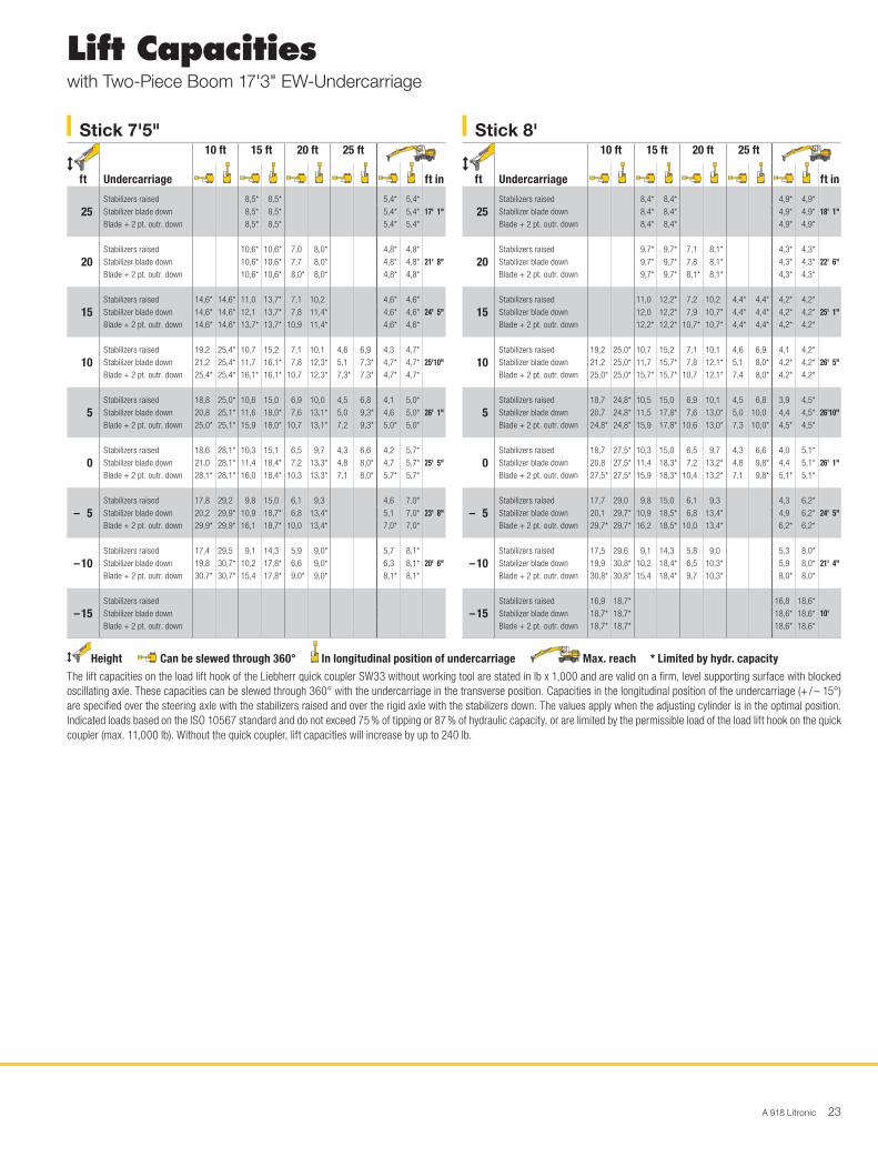
Lift Capacitieswith Two-Piece Boom 17'3" EW-Undercarriage
Height Can be slewed through 360° In longitudinal position of undercarriage Max. reach * Limited by hydr. capacityThe lift capacities on the load lift hook of the Liebherr quick coupler SW33 without working tool are stated in lb x 1,000 and are valid on a firm, level supporting surface with blocked oscillating axle. These capacities can be slewed through 360° with the undercarriage in the transverse position. Capacities in the longitudinal position of the undercarriage (+ / – 15°) are specified over the steering axle with the stabilizers raised and over the rigid axle with the stabilizers down. The values apply when the adjusting cylinder is in the optimal position. Indicated loads based on the ISO 10567 standard and do not exceed 75 % of tipping or 87 % of hydraulic capacity, or are limited by the permissible load of the load lift hook on the quick coupler (max. 11,000 lb). Without the quick coupler, lift capacities will increase by up to 240 lb.
Stick 7'5" ft
Undercarriage
10 ft 15 ft 20 ft 25 ft
ft in
25Stabilizers raised 8,5* 8,5* 5,4* 5,4*
17' 1"Stabilizer blade down 8,5* 8,5* 5,4* 5,4*Blade + 2 pt. outr. down 8,5* 8,5* 5,4* 5,4*
20Stabilizers raised 10,6* 10,6* 7,0 8,0* 4,8* 4,8*
21' 8"Stabilizer blade down 10,6* 10,6* 7,7 8,0* 4,8* 4,8*Blade + 2 pt. outr. down 10,6* 10,6* 8,0* 8,0* 4,8* 4,8*
15Stabilizers raised 14,6* 14,6* 11,0 13,7* 7,1 10,2 4,6* 4,6*
24' 5"Stabilizer blade down 14,6* 14,6* 12,1 13,7* 7,8 11,4* 4,6* 4,6*Blade + 2 pt. outr. down 14,6* 14,6* 13,7* 13,7* 10,9 11,4* 4,6* 4,6*
10Stabilizers raised 19,2 25,4* 10,7 15,2 7,1 10,1 4,6 6,9 4,3 4,7*
25'10"Stabilizer blade down 21,2 25,4* 11,7 16,1* 7,8 12,3* 5,1 7,3* 4,7* 4,7*Blade + 2 pt. outr. down 25,4* 25,4* 16,1* 16,1* 10,7 12,3* 7,3* 7,3* 4,7* 4,7*
5Stabilizers raised 18,8 25,0* 10,6 15,0 6,9 10,0 4,5 6,8 4,1 5,0*
26' 1"Stabilizer blade down 20,8 25,1* 11,6 18,0* 7,6 13,1* 5,0 9,3* 4,6 5,0*Blade + 2 pt. outr. down 25,0* 25,1* 15,9 18,0* 10,7 13,1* 7,2 9,3* 5,0* 5,0*
0Stabilizers raised 18,6 28,1* 10,3 15,1 6,5 9,7 4,3 6,6 4,2 5,7*
25' 5"Stabilizer blade down 21,0 28,1* 11,4 18,4* 7,2 13,3* 4,8 8,0* 4,7 5,7*Blade + 2 pt. outr. down 28,1* 28,1* 16,0 18,4* 10,3 13,3* 7,1 8,0* 5,7* 5,7*
– 5Stabilizers raised 17,8 29,2 9,8 15,0 6,1 9,3 4,6 7,0*
23' 8"Stabilizer blade down 20,2 29,9* 10,9 18,7* 6,8 13,4* 5,1 7,0*Blade + 2 pt. outr. down 29,9* 29,9* 16,1 18,7* 10,0 13,4* 7,0* 7,0*
– 10Stabilizers raised 17,4 29,5 9,1 14,3 5,9 9,0* 5,7 8,1*
20' 6"Stabilizer blade down 19,8 30,7* 10,2 17,8* 6,6 9,0* 6,3 8,1*Blade + 2 pt. outr. down 30,7* 30,7* 15,4 17,8* 9,0* 9,0* 8,1* 8,1*
– 15Stabilizers raisedStabilizer blade downBlade + 2 pt. outr. down
Stick 8' ft
Undercarriage
10 ft 15 ft 20 ft 25 ft
ft in
25Stabilizers raised 8,4* 8,4* 4,9* 4,9*
18' 1"Stabilizer blade down 8,4* 8,4* 4,9* 4,9*Blade + 2 pt. outr. down 8,4* 8,4* 4,9* 4,9*
20Stabilizers raised 9,7* 9,7* 7,1 8,1* 4,3* 4,3*
22' 6"Stabilizer blade down 9,7* 9,7* 7,8 8,1* 4,3* 4,3*Blade + 2 pt. outr. down 9,7* 9,7* 8,1* 8,1* 4,3* 4,3*
15Stabilizers raised 11,0 12,2* 7,2 10,2 4,4* 4,4* 4,2* 4,2*
25' 1"Stabilizer blade down 12,0 12,2* 7,9 10,7* 4,4* 4,4* 4,2* 4,2*Blade + 2 pt. outr. down 12,2* 12,2* 10,7* 10,7* 4,4* 4,4* 4,2* 4,2*
10Stabilizers raised 19,2 25,0* 10,7 15,2 7,1 10,1 4,6 6,9 4,1 4,2*
26' 5"Stabilizer blade down 21,2 25,0* 11,7 15,7* 7,8 12,1* 5,1 8,0* 4,2* 4,2*Blade + 2 pt. outr. down 25,0* 25,0* 15,7* 15,7* 10,7 12,1* 7,4 8,0* 4,2* 4,2*
5Stabilizers raised 18,7 24,8* 10,5 15,0 6,9 10,1 4,5 6,8 3,9 4,5*
26'10"Stabilizer blade down 20,7 24,8* 11,5 17,8* 7,6 13,0* 5,0 10,0 4,4 4,5*Blade + 2 pt. outr. down 24,8* 24,8* 15,9 17,8* 10,6 13,0* 7,3 10,0* 4,5* 4,5*
0Stabilizers raised 18,7 27,5* 10,3 15,0 6,5 9,7 4,3 6,6 4,0 5,1*
26' 1"Stabilizer blade down 20,8 27,5* 11,4 18,3* 7,2 13,2* 4,8 9,8* 4,4 5,1*Blade + 2 pt. outr. down 27,5* 27,5* 15,9 18,3* 10,4 13,2* 7,1 9,8* 5,1* 5,1*
– 5Stabilizers raised 17,7 29,0 9,8 15,0 6,1 9,3 4,3 6,2*
24' 5"Stabilizer blade down 20,1 29,7* 10,9 18,5* 6,8 13,4* 4,9 6,2*Blade + 2 pt. outr. down 29,7* 29,7* 16,2 18,5* 10,0 13,4* 6,2* 6,2*
– 10Stabilizers raised 17,5 29,6 9,1 14,3 5,8 9,0 5,3 8,0*
21' 4"Stabilizer blade down 19,9 30,8* 10,2 18,4* 6,5 10,3* 5,9 8,0*Blade + 2 pt. outr. down 30,8* 30,8* 15,4 18,4* 9,7 10,3* 8,0* 8,0*
– 15Stabilizers raised 16,9 18,7* 16,8 18,6*
10' Stabilizer blade down 18,7* 18,7* 18,6* 18,6*Blade + 2 pt. outr. down 18,7* 18,7* 18,6* 18,6*
24 A 918 Litronic
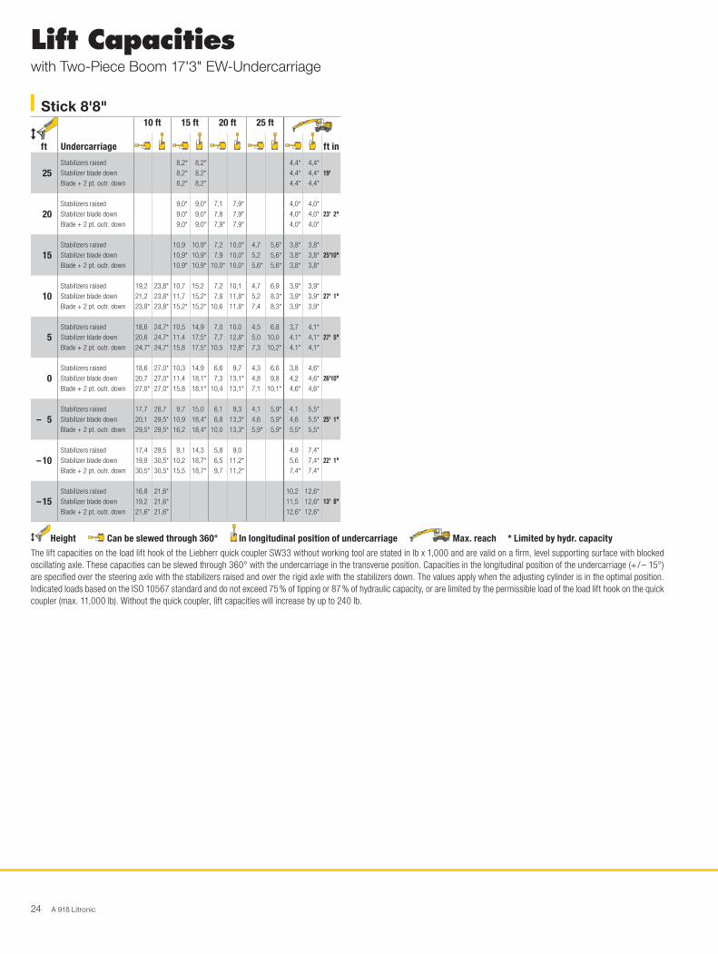
Lift Capacitieswith Two-Piece Boom 17'3" EW-Undercarriage
Height Can be slewed through 360° In longitudinal position of undercarriage Max. reach * Limited by hydr. capacityThe lift capacities on the load lift hook of the Liebherr quick coupler SW33 without working tool are stated in lb x 1,000 and are valid on a firm, level supporting surface with blocked oscillating axle. These capacities can be slewed through 360° with the undercarriage in the transverse position. Capacities in the longitudinal position of the undercarriage (+ / – 15°) are specified over the steering axle with the stabilizers raised and over the rigid axle with the stabilizers down. The values apply when the adjusting cylinder is in the optimal position. Indicated loads based on the ISO 10567 standard and do not exceed 75 % of tipping or 87 % of hydraulic capacity, or are limited by the permissible load of the load lift hook on the quick coupler (max. 11,000 lb). Without the quick coupler, lift capacities will increase by up to 240 lb.
Stick 8'8" ft
Undercarriage
10 ft 15 ft 20 ft 25 ft
ft in
25Stabilizers raised 8,2* 8,2* 4,4* 4,4*
19' Stabilizer blade down 8,2* 8,2* 4,4* 4,4*Blade + 2 pt. outr. down 8,2* 8,2* 4,4* 4,4*
20Stabilizers raised 9,0* 9,0* 7,1 7,9* 4,0* 4,0*
23' 2"Stabilizer blade down 9,0* 9,0* 7,8 7,9* 4,0* 4,0*Blade + 2 pt. outr. down 9,0* 9,0* 7,9* 7,9* 4,0* 4,0*
15Stabilizers raised 10,9 10,9* 7,2 10,0* 4,7 5,6* 3,8* 3,8*
25'10"Stabilizer blade down 10,9* 10,9* 7,9 10,0* 5,2 5,6* 3,8* 3,8*Blade + 2 pt. outr. down 10,9* 10,9* 10,0* 10,0* 5,6* 5,6* 3,8* 3,8*
10Stabilizers raised 19,2 23,8* 10,7 15,2 7,2 10,1 4,7 6,9 3,9* 3,9*
27' 1"Stabilizer blade down 21,2 23,8* 11,7 15,2* 7,8 11,8* 5,2 8,3* 3,9* 3,9*Blade + 2 pt. outr. down 23,8* 23,8* 15,2* 15,2* 10,6 11,8* 7,4 8,3* 3,9* 3,9*
5Stabilizers raised 18,6 24,7* 10,5 14,9 7,0 10,0 4,5 6,8 3,7 4,1*
27' 5"Stabilizer blade down 20,6 24,7* 11,4 17,5* 7,7 12,8* 5,0 10,0 4,1* 4,1*Blade + 2 pt. outr. down 24,7* 24,7* 15,8 17,5* 10,5 12,8* 7,3 10,2* 4,1* 4,1*
0Stabilizers raised 18,6 27,0* 10,3 14,9 6,6 9,7 4,3 6,6 3,8 4,6*
26'10"Stabilizer blade down 20,7 27,0* 11,4 18,1* 7,3 13,1* 4,8 9,8 4,2 4,6*Blade + 2 pt. outr. down 27,0* 27,0* 15,8 18,1* 10,4 13,1* 7,1 10,1* 4,6* 4,6*
– 5Stabilizers raised 17,7 28,7 9,7 15,0 6,1 9,3 4,1 5,9* 4,1 5,5*
25' 1"Stabilizer blade down 20,1 29,5* 10,9 18,4* 6,8 13,3* 4,6 5,9* 4,6 5,5*Blade + 2 pt. outr. down 29,5* 29,5* 16,2 18,4* 10,0 13,3* 5,9* 5,9* 5,5* 5,5*
– 10Stabilizers raised 17,4 29,5 9,1 14,3 5,8 9,0 4,9 7,4*
22' 1"Stabilizer blade down 19,8 30,5* 10,2 18,7* 6,5 11,2* 5,6 7,4*Blade + 2 pt. outr. down 30,5* 30,5* 15,5 18,7* 9,7 11,2* 7,4* 7,4*
– 15Stabilizers raised 16,8 21,6* 10,2 12,6*
13' 8"Stabilizer blade down 19,2 21,6* 11,5 12,6*Blade + 2 pt. outr. down 21,6* 21,6* 12,6* 12,6*

A 918 Litronic 25
Backhoe Bucketwith Mono Boom 16'5"
Operating WeightThe operating weight includes the basic machine with 8 tires plus intermediate rings, mono boom 16'5", stick 8', quick coupler SW33 and bucket 41.3" / 1.05 yd3.
Undercarriage versions Weight (lb)A 918 litronic̀ with stabilizer blade 38,400A 918 litronic̀ with stabilizer blade + 2 pt. outriggers 40,300A 918 litronic̀ with 4 pt. outriggers 40,800A 918 EW litronic̀ with stabilizer blade 38,400A 918 EW litronic̀ with stabilizer blade + 2 pt. outriggers 40,600
Digging Envelopewith quick coupler 1 2 3Stick length ft in 7' 5" 8' 8'8"Max. digging depth ft in 17' 5" 18'1" 18'8"Max. reach at ground level ft in 28'10" 29'6" 30' Max. dumping height ft in 21' 8" 22'2" 22'8"Max. teeth height ft in 31' 6" 32' 32'4"Min. attachment radius ft in 9' 2" 8'4" 8'6"
Digging Forceswithout quick coupler 1 2 3Max. digging force (ISO 6015) lbf 18,277 17,153 16,141
lb 18,300 17,200 16,100Max. breakout force (ISO 6015) lbf 22,346 22,346 22,346
lb 22,300 22,300 22,300Max. breakout force with ripper bucket 28,259 lbf (28,200 lb)
918
25
30
20
15
10
5
-5
-10
-15
-20
0
9
8
10
1 2 3
H1025
30 25 20 15 10 5
10 8 6 4 2 13579
7
6
5
4
3
2
1
0
-1
-2
-3
-4
-5
-7
-6
0
0
m
ft
mft
Buckets Machine stability per ISO 10567* (75 % of tipping capacity)
Cutt
ing
wid
th
Capa
city
IS
O 74
511)
Wei
ght
Stabilizers raised
Stick length (ft in)
Stabilizer blade down
Stick length (ft in)
Stabilizer blade + 2 pt. outriggers
down
Stick length (ft in)
4 point outriggers down
Stick length (ft in)
EW Stabilizers
raised
Stick length (ft in)
EW Stabilizer blade
down
Stick length (ft in)
EW Stabilizer blade
+ 2 pt. outriggers down
Stick length (ft in)
in yd3 lb 7'5" 8' 8'8" 7'5" 8' 8'8" 7'5" 8' 8'8" 7'5" 8' 8'8" 7'5" 8' 8'8" 7'5" 8' 8'8" 7'5" 8' 8'8"19.7"2) 0.39 639 y y y y y y y y y y y y y y y y y y y y y
25.6"2) 0.55 772 y y y y y y y y y y y y y y y y y y y y y
33.5"2) 0.78 882 y y y y y y y y y y y y y y y y y y y y y
41.3"2) 1.05 1,058 y y y y y y y y y y y y y y y y y y y y y
49.2"2) 1.24 1,168 y y V y y y y y y y y y y y y y y y y y y
19.7"3) 0.39 683 y y y y y y y y y y y y y y y y y y y y y
25.6"3) 0.55 794 y y y y y y y y y y y y y y y y y y y y y
33.5"3) 0.78 926 y y y y y y y y y y y y y y y y y y y y y
41.3"3) 1.05 1,102 y y y y y y y y y y y y y y y y y y y y y
49.2"3) 1.24 1,213 y y V y y y y y y y y y y y y y y y y y y
19.7"4) 0.42 617 y y y y y y y y y y y y y y y y y y y y y
25.6"4) 0.59 728 y y y y y y y y y y y y y y y y y y y y y
33.5"4) 0.85 838 y y y y y y y y y y y y y y y y y y y y y
41.3"4) 1.11 1,014 y y y y y y y y y y y y y y y y y y y y y
49.2"4) 1.37 1,102 y V V y y y y y y y y y y y y y y y y y y
* Indicated loads are based on ISO 10567 and do not exceed 75 % of tipping or 87 % of hydraulic capacity, max. stick length without quick coupler, lifted 360° on firm with blocked oscillating axle
1) comparable with SAE (heaped)2) Bucket with teeth 3) Bucket with teeth in HD-version 4) Bucket with cutting edge (also available in HD-version)Buckets with 19.7" cutting width with limited digging depth
Max. material weight y = ≤ 3,034 lb/yd3, y = ≤ 2,528 lb/yd3, V = ≤ 2,023 lb/yd3, – = not authorized

26 A 918 Litronic
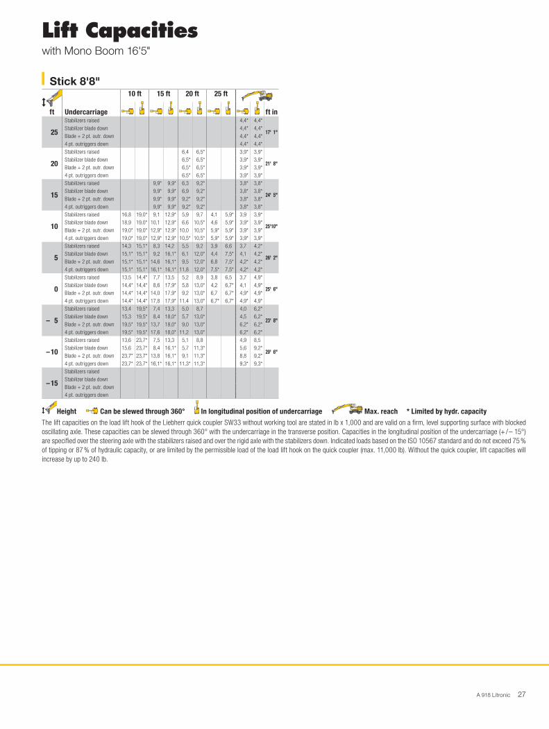
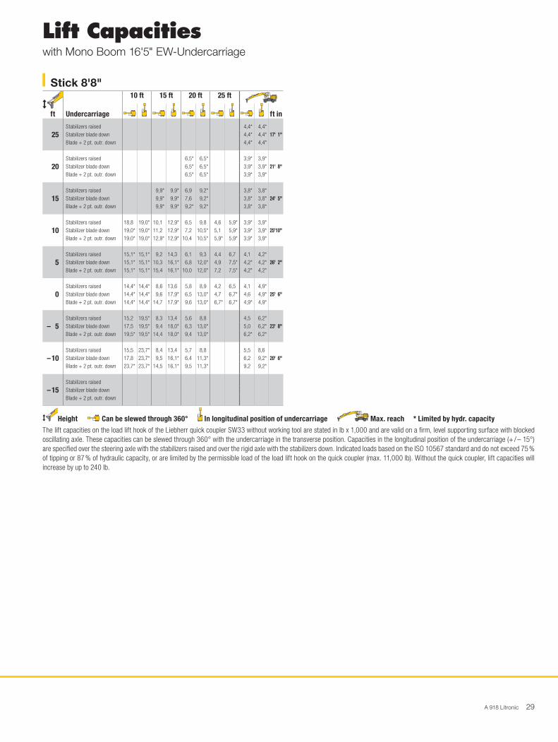
Lift Capacitieswith Mono Boom 16'5"
Height Can be slewed through 360° In longitudinal position of undercarriage Max. reach * Limited by hydr. capacityThe lift capacities on the load lift hook of the Liebherr quick coupler SW33 without working tool are stated in lb x 1,000 and are valid on a firm, level supporting surface with blocked oscillating axle. These capacities can be slewed through 360° with the undercarriage in the transverse position. Capacities in the longitudinal position of the undercarriage (+ / – 15°) are specified over the steering axle with the stabilizers raised and over the rigid axle with the stabilizers down. Indicated loads based on the ISO 10567 standard and do not exceed 75 % of tipping or 87 % of hydraulic capacity, or are limited by the permissible load of the load lift hook on the quick coupler (max. 11,000 lb). Without the quick coupler, lift capacities will increase by up to 240 lb.
Stick 7'5" ft
Undercarriage
10 ft 15 ft 20 ft 25 ft
ft in
25
Stabilizers raised 5,5* 55* 5,3* 5,3*
15' 1"Stabilizer blade down 5,5* 55* 5,3* 5,3*Blade + 2 pt. outr. down 5,5* 55* 5,3* 5,3*4 pt. outriggers down 5,5* 55* 5,3* 5,3*
20
Stabilizers raised 9,5* 95* 5,1* 5,1* 4,7* 4,7*
20' 2"Stabilizer blade down 9,5* 95* 5,1* 5,1* 4,7* 4,7*Blade + 2 pt. outr. down 9,5* 95* 5,1* 5,1* 4,7* 4,7*4 pt. outriggers down 9,5* 95* 5,1* 5,1* 4,7* 4,7*
15
Stabilizers raised 9,8 11,0* 6,2 10,0 4,6* 4,6*
23' 1"Stabilizer blade down 10,8 11,0* 6,9 10,0* 4,6* 4,6*Blade + 2 pt. outr. down 11,0* 11,0* 10,0* 10,0* 4,6* 4,6*4 pt. outriggers down 11,0* 11,0* 10,1* 10,1* 4,6* 4,6*
10
Stabilizers raised 16,2 21,9* 9,0 14,0* 5,9 9,7 4,3 4,8*
24' 6"Stabilizer blade down 18,3 21,9* 10,0 14,0* 6,6 11,2* 4,8 4,8*Blade + 2 pt. outr. down 21,9* 21,9* 14,0* 14,0* 10,0 11,2* 4,8* 4,8*4 pt. outriggers down 21,9* 21,9* 14,0* 14,0* 11,2* 11,2* 4,8* 4,8*
5
Stabilizers raised 11,1* 11,1* 8,2 14,2 5,5 9,3 4,0 5,2*
24'11"Stabilizer blade down 11,1* 11,1* 9,2 16,9* 6,2 12,5* 4,5 5,2*Blade + 2 pt. outr. down 11,1* 11,1* 14,6 16,9* 9,6 12,5* 5,2* 5,2*4 pt. outriggers down 11,1* 11,1* 16,9* 16,9* 11,8 12,5* 5,2* 5,2*
0
Stabilizers raised 13,7 14,2* 7,7 13,6 5,3 9,0 4,1 6,1*
24' 2"Stabilizer blade down 14,2* 14,2* 8,7 18,3* 5,9 13,3* 4,6 6,1*Blade + 2 pt. outr. down 14,2* 14,2* 14,0 18,3* 9,2 13,3* 6,1* 6,1*4 pt. outriggers down 14,2* 14,2* 17,9 18,3* 11,5 13,3* 6,1* 6,1*
– 5
Stabilizers raised 13,7 21,2* 7,6 13,4 5,2 8,9 4,5 7,6
22' 4"Stabilizer blade down 15,7 21,2* 8,5 17,9* 5,8 13,0* 5,0 8,0*Blade + 2 pt. outr. down 21,2* 21,2* 13,9 17,9* 9,1 13,0* 7,9 8,0*4 pt. outriggers down 21,2* 21,2* 17,7 17,9* 11,4 12,9* 8,0* 8,0*
– 10
Stabilizers raised 14,0 22,2* 7,7 13,6 5,7 9,8
18'10"Stabilizer blade down 16,0 22,2* 8,7 15,4* 6,4 11,5*Blade + 2 pt. outr. down 22,2* 22,2* 14,0 15,4* 10,1 11,5*4 pt. outriggers down 22,2* 22,2* 15,4* 15,4* 11,5* 11,5*
– 15
Stabilizers raisedStabilizer blade downBlade + 2 pt. outr. down4 pt. outriggers down
Stick 8' ft
Undercarriage
10 ft 15 ft 20 ft 25 ft
ft in
25
Stabilizers raised 6,5* 6,5* 4,8* 4,8*
16' 1"Stabilizer blade down 6,5* 6,5* 4,8* 4,8*Blade + 2 pt. outr. down 6,5* 6,5* 4,8* 4,8*4 pt. outriggers down 6,5* 6,5* 4,8* 4,8*
20
Stabilizers raised 9,0* 9,0* 6,1* 6,1* 4,3* 4,3*
21' Stabilizer blade down 9,0* 9,0* 6,1* 6,1* 4,3* 4,3*Blade + 2 pt. outr. down 9,0* 9,0* 6,1* 6,1* 4,3* 4,3*4 pt. outriggers down 9,0* 9,0* 6,1* 6,1* 4,3* 4,3*
15
Stabilizers raised 9,9 10,5* 6,3 9,7* 4,2* 4,2*
23' 8"Stabilizer blade down 10,5* 10,5* 6,9 9,7* 4,2* 4,2*Blade + 2 pt. outr. down 10,5* 10,5* 9,7* 9,7* 4,2* 4,2*4 pt. outriggers down 10,5* 10,5* 9,7* 9,7* 4,2* 4,2*
10
Stabilizers raised 16,5 20,4* 9,1 13,4* 5,9 9,7 4,1 4,8* 4,1 4,3*
25' 2"Stabilizer blade down 18,6 20,4* 10,1 13,4* 6,6 10,9* 4,6 4,8* 4,3* 4,3*Blade + 2 pt. outr. down 20,4* 20,4* 13,4* 13,4* 10,0 10,9* 4,8* 4,8* 4,3* 4,3*4 pt. outriggers down 20,4* 20,4* 13,4* 13,4* 10,9* 10,9* 4,8* 4,8* 4,3* 4,3*
5
Stabilizers raised 13,0* 13,0* 8,2 14,2 5,5 9,3 4,0 6,5* 3,8 4,7*
25' 6"Stabilizer blade down 13,0* 13,0* 9,2 16,5* 6,2 12,2* 4,4 6,5* 4,3 4,7*Blade + 2 pt. outr. down 13,0* 13,0* 14,6 16,5* 9,5 12,2* 6,5* 6,5* 4,7* 4,7*4 pt. outriggers down 13,0* 13,0* 16,5* 16,5* 11,8 12,2* 6,5* 6,5* 4,7* 4,7*
0
Stabilizers raised 13,6 14,3* 7,7 13,6 5,2 8,9 3,9 5,5*
24'10"Stabilizer blade down 14,3* 14,3* 8,7 18,1* 5,9 13,1* 4,3 5,5*Blade + 2 pt. outr. down 14,3* 14,3* 14,0 18,1* 9,2 13,1* 5,5* 5,5*4 pt. outriggers down 14,3* 14,3* 17,9 18,1* 11,5 13,1* 5,5* 5,5*
– 5
Stabilizers raised 13,5 20,3* 7,5 13,4 5,1 8,8 4,3 7,0*
23' Stabilizer blade down 15,5 20,3* 8,5 18,0* 5,7 13,0* 4,8 7,0*Blade + 2 pt. outr. down 20,3* 20,3* 13,8 18,0* 9,1 13,0* 7,0* 7,0*4 pt. outriggers down 20,3* 20,3* 17,6 18,0* 11,3 13,0* 7,0* 7,0*
– 10
Stabilizers raised 13,8 23,0* 7,6 13,5 5,3 9,1
19' 8"Stabilizer blade down 15,8 23,0* 8,6 15,8* 6,0 11,0*Blade + 2 pt. outr. down 23,0* 23,0* 13,9 15,8* 9,4 11,0*4 pt. outriggers down 23,0* 23,0* 15,8* 15,8* 11,0* 11,0*
– 15
Stabilizers raisedStabilizer blade downBlade + 2 pt. outr. down4 pt. outriggers down
A 918 Litronic 27
Lift Capacitieswith Mono Boom 16'5"
Height Can be slewed through 360° In longitudinal position of undercarriage Max. reach * Limited by hydr. capacityThe lift capacities on the load lift hook of the Liebherr quick coupler SW33 without working tool are stated in lb x 1,000 and are valid on a firm, level supporting surface with blocked oscillating axle. These capacities can be slewed through 360° with the undercarriage in the transverse position. Capacities in the longitudinal position of the undercarriage (+ / – 15°) are specified over the steering axle with the stabilizers raised and over the rigid axle with the stabilizers down. Indicated loads based on the ISO 10567 standard and do not exceed 75 % of tipping or 87 % of hydraulic capacity, or are limited by the permissible load of the load lift hook on the quick coupler (max. 11,000 lb). Without the quick coupler, lift capacities will increase by up to 240 lb.
Stick 8'8" ft
Undercarriage
10 ft 15 ft 20 ft 25 ft
ft in
25
Stabilizers raised 4,4* 4,4*
17' 1"Stabilizer blade down 4,4* 4,4*Blade + 2 pt. outr. down 4,4* 4,4*4 pt. outriggers down 4,4* 4,4*
20
Stabilizers raised 6,4 6,5* 3,9* 3,9*
21' 8"Stabilizer blade down 6,5* 6,5* 3,9* 3,9*Blade + 2 pt. outr. down 6,5* 6,5* 3,9* 3,9*4 pt. outriggers down 6,5* 6,5* 3,9* 3,9*
15
Stabilizers raised 9,9* 9,9* 6,3 9,2* 3,8* 3,8*
24' 5"Stabilizer blade down 9,9* 9,9* 6,9 9,2* 3,8* 3,8*Blade + 2 pt. outr. down 9,9* 9,9* 9,2* 9,2* 3,8* 3,8*4 pt. outriggers down 9,9* 9,9* 9,2* 9,2* 3,8* 3,8*
10
Stabilizers raised 16,8 19,0* 9,1 12,9* 5,9 9,7 4,1 5,9* 3,9 3,9*
25'10"Stabilizer blade down 18,9 19,0* 10,1 12,9* 6,6 10,5* 4,6 5,9* 3,9* 3,9*Blade + 2 pt. outr. down 19,0* 19,0* 12,9* 12,9* 10,0 10,5* 5,9* 5,9* 3,9* 3,9*4 pt. outriggers down 19,0* 19,0* 12,9* 12,9* 10,5* 10,5* 5,9* 5,9* 3,9* 3,9*
5
Stabilizers raised 14,3 15,1* 8,3 14,2 5,5 9,2 3,9 6,6 3,7 4,2*
26' 2"Stabilizer blade down 15,1* 15,1* 9,2 16,1* 6,1 12,0* 4,4 7,5* 4,1 4,2*Blade + 2 pt. outr. down 15,1* 15,1* 14,6 16,1* 9,5 12,0* 6,8 7,5* 4,2* 4,2*4 pt. outriggers down 15,1* 15,1* 16,1* 16,1* 11,8 12,0* 7,5* 7,5* 4,2* 4,2*
0
Stabilizers raised 13,5 14,4* 7,7 13,5 5,2 8,9 3,8 6,5 3,7 4,9*
25' 6"Stabilizer blade down 14,4* 14,4* 8,6 17,9* 5,8 13,0* 4,2 6,7* 4,1 4,9*Blade + 2 pt. outr. down 14,4* 14,4* 14,0 17,9* 9,2 13,0* 6,7 6,7* 4,9* 4,9*4 pt. outriggers down 14,4* 14,4* 17,8 17,9* 11,4 13,0* 6,7* 6,7* 4,9* 4,9*
– 5
Stabilizers raised 13,4 19,5* 7,4 13,3 5,0 8,7 4,0 6,2*
23' 8"Stabilizer blade down 15,3 19,5* 8,4 18,0* 5,7 13,0* 4,5 6,2*Blade + 2 pt. outr. down 19,5* 19,5* 13,7 18,0* 9,0 13,0* 6,2* 6,2*4 pt. outriggers down 19,5* 19,5* 17,6 18,0* 11,2 13,0* 6,2* 6,2*
– 10
Stabilizers raised 13,6 23,7* 7,5 13,3 5,1 8,8 4,9 8,5
20' 6"Stabilizer blade down 15,6 23,7* 8,4 16,1* 5,7 11,3* 5,6 9,2*Blade + 2 pt. outr. down 23,7* 23,7* 13,8 16,1* 9,1 11,3* 8,8 9,2*4 pt. outriggers down 23,7* 23,7* 16,1* 16,1* 11,3* 11,3* 9,3* 9,3*
– 15
Stabilizers raisedStabilizer blade downBlade + 2 pt. outr. down4 pt. outriggers down
28 A 918 Litronic
Lift Capacitieswith Mono Boom 16'5" EW-Undercarriage
Height Can be slewed through 360° In longitudinal position of undercarriage Max. reach * Limited by hydr. capacityThe lift capacities on the load lift hook of the Liebherr quick coupler SW33 without working tool are stated in lb x 1,000 and are valid on a firm, level supporting surface with blocked oscillating axle. These capacities can be slewed through 360° with the undercarriage in the transverse position. Capacities in the longitudinal position of the undercarriage (+ / – 15°) are specified over the steering axle with the stabilizers raised and over the rigid axle with the stabilizers down. Indicated loads based on the ISO 10567 standard and do not exceed 75 % of tipping or 87 % of hydraulic capacity, or are limited by the permissible load of the load lift hook on the quick coupler (max. 11,000 lb). Without the quick coupler, lift capacities will increase by up to 240 lb.
Stick 7'5" ft
Undercarriage
10 ft 15 ft 20 ft 25 ft
ft in
25Stabilizers raised 5,5* 5,5* 5,3* 5,3*
15' 1"Stabilizer blade down 5,5* 5,5* 5,3* 5,3*Blade + 2 pt. outr. down 5,5* 5,5* 5,3* 5,3*
20Stabilizers raised 9,5* 9,5* 5,1* 5,1* 4,7* 4,7*
20' 2"Stabilizer blade down 9,5* 9,5* 5,1* 5,1* 4,7* 4,7*Blade + 2 pt. outr. down 9,5* 9,5* 5,1* 5,1* 4,7* 4,7*
15Stabilizers raised 10,8 11,0* 6,8 10,0* 4,6* 4,6*
23' 1"Stabilizer blade down 11,0* 11,0* 7,6 10,0* 4,6* 4,6*Blade + 2 pt. outr. down 11,0* 11,0* 10,0* 10,0* 4,6* 4,6*
10Stabilizers raised 18,2 21,9* 10,0 14,0* 6,5 9,7 4,7 4,8*
24' 6"Stabilizer blade down 20,6 21,9* 11,1 14,0* 7,2 11,2* 4,8* 4,8*Blade + 2 pt. outr. down 21,9* 21,9* 14,0* 14,0* 10,4 11,2* 4,8* 4,8*
5Stabilizers raised 11,1* 11,1* 9,1 14,3 6,1 9,3 4,5 5,2*
24'11"Stabilizer blade down 11,1* 11,1* 10,2 16,9* 6,8 12,5* 5,0 5,2*Blade + 2 pt. outr. down 11,1* 11,1* 15,4 16,9* 10,0 12,5* 5,2* 5,2*
0Stabilizers raised 14,2* 14,2* 8,6 13,7 5,9 9,0 4,5 6,1*
24' 2"Stabilizer blade down 14,2* 14,2* 9,7 18,3* 6,6 13,3* 5,1 6,1*Blade + 2 pt. outr. down 14,2* 14,2* 14,8 18,3* 9,7 13,3* 6,1* 6,1*
– 5Stabilizers raised 15,6 21,2* 8,5 13,5 5,8 8,9 5,0 7,7
22' 4"Stabilizer blade down 17,8 21,2* 9,6 17,9* 6,5 13,0* 5,6 8,0*Blade + 2 pt. outr. down 21,2* 21,2* 14,6 17,9* 9,6 13,0* 8,0* 8,0*
– 10Stabilizers raised 15,9 22,2* 8,6 13,7 6,4 9,8
18'10"Stabilizer blade down 18,2 22,2* 9,7 15,4* 7,1 11,5*Blade + 2 pt. outr. down 22,2* 22,2* 14,8 15,4* 10,6 11,5*
– 15Stabilizers raisedStabilizer blade downBlade + 2 pt. outr. down
Stick 8' ft
Undercarriage
10 ft 15 ft 20 ft 25 ft
ft in
25Stabilizers raised 6,5* 6,5* 4,8* 4,8*
16' 1"Stabilizer blade down 6,5* 6,5* 4,8* 4,8*Blade + 2 pt. outr. down 6,5* 6,5* 4,8* 4,8*
20Stabilizers raised 9,0* 9,0* 6,1* 6,1* 4,3* 4,3*
21' Stabilizer blade down 9,0* 9,0* 6,1* 6,1* 4,3* 4,3*Blade + 2 pt. outr. down 9,0* 9,0* 6,1* 6,1* 4,3* 4,3*
15Stabilizers raised 10,5* 10,5* 6,9 9,7* 4,2* 4,2*
23' 8"Stabilizer blade down 10,5* 10,5* 7,6 9,7* 4,2* 4,2*Blade + 2 pt. outr. down 10,5* 10,5* 9,7* 9,7* 4,2* 4,2*
10Stabilizers raised 18,5 20,4* 10,0 13,4* 6,5 9,7 4,6 4,8* 4,3* 4,3*
25' 2"Stabilizer blade down 20,4* 20,4* 11,1 13,4* 7,2 10,9* 4,8* 4,8* 4,3* 4,3*Blade + 2 pt. outr. down 20,4* 20,4* 13,4* 13,4* 10,4 10,9* 4,8* 4,8* 4,3* 4,3*
5Stabilizers raised 13,0* 13,0* 9,2 14,3 6,1 9,3 4,4 6,5* 4,3 4,7*
25' 6"Stabilizer blade down 13,0* 13,0* 10,3 16,5* 6,8 12,2* 4,9 6,5* 4,7* 4,7*Blade + 2 pt. outr. down 13,0* 13,0* 15,4 16,5* 10,0 12,2* 6,5* 6,5* 4,7* 4,7*
0Stabilizers raised 14,3* 14,3* 8,6 13,7 5,8 9,0 4,3 5,5*
24'10"Stabilizer blade down 14,3* 14,3* 9,7 18,1* 6,5 13,1* 4,8 5,5*Blade + 2 pt. outr. down 14,3* 14,3* 14,8 18,1* 9,7 13,1* 5,5* 5,5*
– 5Stabilizers raised 15,4 20,3* 8,4 13,4 5,7 8,8 4,7 7,0*
23' Stabilizer blade down 17,7 20,3* 9,5 18,0* 6,4 13,0* 5,3 7,0*Blade + 2 pt. outr. down 20,3* 20,3* 14,5 18,0* 9,5 13,0* 7,0* 7,0*
– 10Stabilizers raised 15,7 23,0* 8,5 13,5 5,9 9,2
19' 8"Stabilizer blade down 18,0 23,0* 9,6 15,8* 6,6 11,0*Blade + 2 pt. outr. down 23,0* 23,0* 14,6 15,8* 9,9 11,0*
– 15Stabilizers raisedStabilizer blade downBlade + 2 pt. outr. down
A 918 Litronic 29
Lift Capacitieswith Mono Boom 16'5" EW-Undercarriage
Height Can be slewed through 360° In longitudinal position of undercarriage Max. reach * Limited by hydr. capacityThe lift capacities on the load lift hook of the Liebherr quick coupler SW33 without working tool are stated in lb x 1,000 and are valid on a firm, level supporting surface with blocked oscillating axle. These capacities can be slewed through 360° with the undercarriage in the transverse position. Capacities in the longitudinal position of the undercarriage (+ / – 15°) are specified over the steering axle with the stabilizers raised and over the rigid axle with the stabilizers down. Indicated loads based on the ISO 10567 standard and do not exceed 75 % of tipping or 87 % of hydraulic capacity, or are limited by the permissible load of the load lift hook on the quick coupler (max. 11,000 lb). Without the quick coupler, lift capacities will increase by up to 240 lb.
Stick 8'8" ft
Undercarriage
10 ft 15 ft 20 ft 25 ft
ft in
25Stabilizers raised 4,4* 4,4*
17' 1"Stabilizer blade down 4,4* 4,4*Blade + 2 pt. outr. down 4,4* 4,4*
20Stabilizers raised 6,5* 6,5* 3,9* 3,9*
21' 8"Stabilizer blade down 6,5* 6,5* 3,9* 3,9*Blade + 2 pt. outr. down 6,5* 6,5* 3,9* 3,9*
15Stabilizers raised 9,9* 9,9* 6,9 9,2* 3,8* 3,8*
24' 5"Stabilizer blade down 9,9* 9,9* 7,6 9,2* 3,8* 3,8*Blade + 2 pt. outr. down 9,9* 9,9* 9,2* 9,2* 3,8* 3,8*
10Stabilizers raised 18,8 19,0* 10,1 12,9* 6,5 9,8 4,6 5,9* 3,9* 3,9*
25'10"Stabilizer blade down 19,0* 19,0* 11,2 12,9* 7,2 10,5* 5,1 5,9* 3,9* 3,9*Blade + 2 pt. outr. down 19,0* 19,0* 12,9* 12,9* 10,4 10,5* 5,9* 5,9* 3,9* 3,9*
5Stabilizers raised 15,1* 15,1* 9,2 14,3 6,1 9,3 4,4 6,7 4,1 4,2*
26' 2"Stabilizer blade down 15,1* 15,1* 10,3 16,1* 6,8 12,0* 4,9 7,5* 4,2* 4,2*Blade + 2 pt. outr. down 15,1* 15,1* 15,4 16,1* 10,0 12,0* 7,2 7,5* 4,2* 4,2*
0Stabilizers raised 14,4* 14,4* 8,6 13,6 5,8 8,9 4,2 6,5 4,1 4,9*
25' 6"Stabilizer blade down 14,4* 14,4* 9,6 17,9* 6,5 13,0* 4,7 6,7* 4,6 4,9*Blade + 2 pt. outr. down 14,4* 14,4* 14,7 17,9* 9,6 13,0* 6,7* 6,7* 4,9* 4,9*
– 5Stabilizers raised 15,2 19,5* 8,3 13,4 5,6 8,8 4,5 6,2*
23' 8"Stabilizer blade down 17,5 19,5* 9,4 18,0* 6,3 13,0* 5,0 6,2*Blade + 2 pt. outr. down 19,5* 19,5* 14,4 18,0* 9,4 13,0* 6,2* 6,2*
– 10Stabilizers raised 15,5 23,7* 8,4 13,4 5,7 8,8 5,5 8,6
20' 6"Stabilizer blade down 17,8 23,7* 9,5 16,1* 6,4 11,3* 6,2 9,2*Blade + 2 pt. outr. down 23,7* 23,7* 14,5 16,1* 9,5 11,3* 9,2 9,2*
– 15Stabilizers raisedStabilizer blade downBlade + 2 pt. outr. down
30 A 918 Litronic
Backhoe Bucketwith Offset Two-Piece Boom 16'5"
Operating WeightThe operating weight includes the basic machine with 8 tires plus intermediate rings, offset two-piece boom 16'5", stick 8', quick coupler SW33 and bucket 41.3" / 1.05 yd3.
Undercarriage versions Weight (lb)A 918 litronic̀ with stabilizer blade 40,300A 918 litronic̀ with stabilizer blade + 2 pt. outriggers 42,500A 918 litronic̀ with 4 pt. outriggers 43,000A 918 EW litronic̀ with stabilizer blade 40,600A 918 EW litronic̀ with stabilizer blade + 2 pt. outriggers 42,800
Digging Envelopewith quick coupler 4 5 6Stick length ft in 7'5" 8' 8'8"Max. digging depth ft in 18'4" 19' 19'8"Max. reach at ground level ft in 29' 29' 8" 30'4"Max. dumping height ft in 23'5" 23'11" 24'7"Max. teeth height ft in 33'4" 33'10" 34'3"Min. attachment radius ft in 10'2" 9' 4" 9'
1 with stick 7'5" 4 with stick 7'5"2 with stick 8' 5 with stick 8'3 with stick 8'8" 6 with stick 8'8"at max. attachment offset with set straight boom with vertical ditch walls
Digging Forceswithout quick coupler 4 5 6Max. digging force (ISO 6015) lbf 18,277 17,153 16,141
lb 18,300 17,200 16,100Max. breakout force (ISO 6015) lbf 22,346 22,346 22,346
lb 22,300 22,300 22,300Max. breakout force with ripper bucket 28,259 lbf (28,200 lb)
918
25
30
35
20
15
10
5
-5
-10
-15
0
8
9
10
11
12 3
456
H1026
30 25 20 15 10 5
10 8 6 4 2 13579
7
6
5
4
3
2
1
0
-1
-2
-3
-4
-5
-60
0
m
ft
mft
2480
R 238
035°
39°
2480
Buckets Machine stability per ISO 10567* (75 % of tipping capacity)
Cutt
ing
wid
th
Capa
city
IS
O 74
511)
Wei
ght
Stabilizers raised
Stick length (ft in)
Stabilizer blade down
Stick length (ft in)
Stabilizer blade + 2 pt. outriggers
down
Stick length (ft in)
4 point outriggers down
Stick length (ft in)
EW Stabilizers
raised
Stick length (ft in)
EW Stabilizer blade
down
Stick length (ft in)
EW Stabilizer blade
+ 2 pt. outriggers down
Stick length (ft in)
in yd3 lb 7'5" 8' 8'8" 7'5" 8' 8'8" 7'5" 8' 8'8" 7'5" 8' 8'8" 7'5" 8' 8'8" 7'5" 8' 8'8" 7'5" 8' 8'8"33.5"2) 0.78 882 y y y y y y y y y y y y y y y y y y y y y
41.3"2) 1.05 1,058 y y V y y y y y y y y y y y y y y y y y y
49.2"2) 1.24 1,168 V V V y y V y y y y y y y y V y y y y y y
33.5"3) 0.78 926 y y y y y y y y y y y y y y y y y y y y y
41.3"3) 1.05 1,102 y y V y y y y y y y y y y y y y y y y y y
49.2"3) 1.24 1,213 V V – y y V y y y y y y y V V y y y y y y
33.5"4) 0.85 838 y y y y y y y y y y y y y y y y y y y y y
41.3"4) 1.11 1,014 y y V y y y y y y y y y y y y y y y y y y
49.2"4) 1.37 1,102 V – – V V V y y y y y y V V V y y y y y y
* Indicated loads are based on ISO 10567 and do not exceed 75 % of tipping or 87 % of hydraulic capacity, max. stick length without quick coupler, lifted 360° on firm with blocked oscillating axle
1) comparable with SAE (heaped)2) Bucket with teeth 3) Bucket with teeth in HD-version 4) Bucket with cutting edge (also available in HD-version)
Max. material weight y = ≤ 3,034 lb/yd3, y = ≤ 2,528 lb/yd3, V = ≤ 2,023 lb/yd3, – = not authorized
A 918 Litronic 31
Lift Capacitieswith Offset Two-Piece Boom 16'5"
Height Can be slewed through 360° In longitudinal position of undercarriage Max. reach * Limited by hydr. capacityThe lift capacities on the load lift hook of the Liebherr quick coupler SW33 without working tool are stated in lb x 1,000 and are valid on a firm, level supporting surface with blocked oscillating axle. These capacities can be slewed through 360° with the undercarriage in the transverse position. Capacities in the longitudinal position of the undercarriage (+ / – 15°) are specified over the steering axle with the stabilizers raised and over the rigid axle with the stabilizers down. The values apply when the adjusting cylinder is in the optimal position. Indicated loads based on the ISO 10567 standard and do not exceed 75 % of tipping or 87 % of hydraulic capacity, or are limited by the permissible load of the load lift hook on the quick coupler (max. 11,000 lb). Without the quick coupler, lift capacities will increase by up to 240 lb.
Stick 7'5" ft
Undercarriage
10 ft 15 ft 20 ft 25 ft
ft in
25
Stabilizers raised 6,6* 6,6* 5,1* 5,1*
15'10"Stabilizer blade down 6,6* 6,6* 5,1* 5,1*Blade + 2 pt. outr. down 6,6* 6,6* 5,1* 5,1*4 pt. outriggers down 6,6* 6,6* 5,1* 5,1*
20
Stabilizers raised 10,2 10,3* 6,1 6,1* 4,4* 4,4*
20' 8"Stabilizer blade down 10,3* 10,3* 6,1* 6,1* 4,4* 4,4*Blade + 2 pt. outr. down 10,3* 10,3* 6,1* 6,1* 4,4* 4,4*4 pt. outriggers down 10,3* 10,3* 6,1* 6,1* 4,4* 4,4*
15
Stabilizers raised 13,5* 13,5* 10,1 13,1* 6,2 9,9 4,2* 4,2*
23' 6"Stabilizer blade down 13,5* 13,5* 11,0 13,1* 6,9 10,5* 4,2* 4,2*Blade + 2 pt. outr. down 13,5* 13,5* 13,1* 13,1* 10,2 10,5* 4,2* 4,2*4 pt. outriggers down 13,6* 13,6* 13,1* 13,1* 10,5* 10,5* 4,2* 4,2*
10
Stabilizers raised 17,3 24,2* 9,7 14,9 6,2 9,9 3,7 4,3*
25' Stabilizer blade down 19,0 24,2* 10,6 15,3* 6,8 11,8* 4,2 4,3*Blade + 2 pt. outr. down 24,2* 24,2* 15,2 15,3* 10,1 11,8* 4,3* 4,3*4 pt. outriggers down 24,2* 24,2* 15,3* 15,3* 11,8* 11,8* 4,3* 4,3*
5
Stabilizers raised 16,8 25,3* 9,6 14,6 5,9 9,6 3,6 6,0* 3,5 4,7*
25' 4"Stabilizer blade down 18,5 25,3* 10,5 17,1* 6,5 12,5* 4,0 6,0* 3,9 4,7*Blade + 2 pt. outr. down 25,3* 25,3* 14,9 17,1* 9,9 12,5* 6,0* 6,0* 4,7* 4,7*4 pt. outriggers down 25,4* 25,4* 17,1* 17,1* 11,9 12,5* 6,0* 6,0* 4,7* 4,7*
0
Stabilizers raised 16,4 27,5 9,1 14,8 5,4 9,2 3,5 5,3*
24' 7"Stabilizer blade down 18,5 27,7* 10,1 17,5* 6,1 12,7* 4,0 5,3*Blade + 2 pt. outr. down 27,7* 27,7* 15,1 17,5* 9,5 12,7* 5,3* 5,3*4 pt. outriggers down 27,7* 27,7* 17,5* 17,5* 11,7 12,7* 5,3* 5,3*
– 5
Stabilizers raised 15,3 28,5 8,3 14,4 4,9 8,7 3,9 6,7*
22'10"Stabilizer blade down 17,4 28,9* 9,3 18,0* 5,6 12,4* 4,4 6,7*Blade + 2 pt. outr. down 28,8 28,9* 14,9 18,0* 9,0 12,4* 6,7* 6,7*4 pt. outriggers down 28,9* 28,9* 18,0* 18,0* 11,3 12,4* 6,7* 6,7*
– 10
Stabilizers raised 14,6 28,5 7,5 13,6 5,0 7,9*
19' 5"Stabilizer blade down 16,7 29,0* 8,5 16,1* 5,6 7,9*Blade + 2 pt. outr. down 29,0* 29,0* 14,0 16,1* 7,9* 7,9*4 pt. outriggers down 29,0* 29,0* 16,1* 16,1* 7,9* 7,9*
– 15
Stabilizers raisedStabilizer blade downBlade + 2 pt. outr. down4 pt. outriggers down
Stick 8' ft
Undercarriage
10 ft 15 ft 20 ft 25 ft
ft in
25
Stabilizers raised 7,2* 7,2* 4,6* 4,6*
16'10"Stabilizer blade down 7,2* 7,2* 4,6* 4,6*Blade + 2 pt. outr. down 7,2* 7,2* 4,6* 4,6*4 pt. outriggers down 7,3* 7,3* 4,6* 4,6*
20
Stabilizers raised 9,5* 9,5* 6,2 6,8* 4,0* 4,0*
21' 6"Stabilizer blade down 9,5* 9,5* 6,8* 6,8* 4,0* 4,0*Blade + 2 pt. outr. down 9,5* 9,5* 6,8* 6,8* 4,0* 4,0*4 pt. outriggers down 9,5* 9,5* 6,8* 6,8* 4,0* 4,0*
15
Stabilizers raised 10,1 11,8* 6,3 9,9 3,8* 3,8*
24' 2"Stabilizer blade down 11,0 11,8* 7,0 10,0* 3,8* 3,8*Blade + 2 pt. outr. down 11,8* 11,8* 10,0* 10,0* 3,8* 3,8*4 pt. outriggers down 11,8* 11,8* 10,0* 10,0* 3,8* 3,8*
10
Stabilizers raised 17,3 23,1* 9,7 14,9 6,3 9,9 3,8 5,8* 3,5 3,9*
25' 7"Stabilizer blade down 19,1 23,1* 10,6 14,9* 6,9 11,6* 4,2 5,8* 3,9* 3,9*Blade + 2 pt. outr. down 23,1* 23,1* 14,9* 14,9* 10,1 11,6* 5,8* 5,8* 3,9* 3,9*4 pt. outriggers down 23,1* 23,1* 14,9* 14,9* 11,6* 11,6* 5,8* 5,8* 3,9* 3,9*
5
Stabilizers raised 16,7* 25,2* 9,5 14,6 6,0 9,7 3,6 6,3 3,3 4,2*
25'11"Stabilizer blade down 18,4 25,2* 10,4 16,9* 6,6 12,4* 4,1 7,5* 3,7 4,2*Blade + 2 pt. outr. down 25,2* 25,2* 14,9 16,9* 10,0 12,4* 6,5 7,5* 4,2* 4,2*4 pt. outriggers down 25,2* 25,2* 16,9* 16,9* 11,8 12,4* 7,5* 7,5* 4,2* 4,2*
0
Stabilizers raised 16,5 27,3 9,1 14,7 5,5 9,2 3,4 6,0* 3,3 4,8*
25' 4"Stabilizer blade down 18,6 27,3* 10,2 17,4* 6,1 12,6* 3,9 6,0* 3,8 4,8*Blade + 2 pt. outr. down 27,3* 27,3* 15,0 17,4* 9,5 12,6* 6,0* 6,0* 4,8* 4,8*4 pt. outriggers down 27,3* 27,3* 17,4* 17,4* 11,8 12,6* 6,0* 6,0* 4,8* 4,8*
– 5
Stabilizers raised 15,3 28,2 8,5 14,5 5,0 8,8 3,6 5,9*
23' 6"Stabilizer blade down 17,4 28,6* 9,5 17,8* 5,6 12,6* 4,2 5,9*Blade + 2 pt. outr. down 28,5 28,6* 15,0 17,8* 9,0 12,6* 5,9* 5,9*4 pt. outriggers down 28,6* 28,6* 17,8* 17,8* 11,3 12,6* 5,9* 5,9*
– 10
Stabilizers raised 14,7 28,7 7,5 13,6 4,7 8,2* 4,6 7,8*
20' 2"Stabilizer blade down 16,8 29,7* 8,5 17,0* 5,3 8,2* 5,2 7,8*Blade + 2 pt. outr. down 29,6 29,7* 14,1 17,0* 8,2* 8,2* 7,8* 7,8*4 pt. outriggers down 29,7* 29,7* 17,0* 17,0* 8,2* 8,2* 7,8* 7,8*
– 15
Stabilizers raisedStabilizer blade downBlade + 2 pt. outr. down4 pt. outriggers down

32 A 918 Litronic
Lift Capacitieswith Offset Two-Piece Boom 16'5"
Height Can be slewed through 360° In longitudinal position of undercarriage Max. reach * Limited by hydr. capacityThe lift capacities on the load lift hook of the Liebherr quick coupler SW33 without working tool are stated in lb x 1,000 and are valid on a firm, level supporting surface with blocked oscillating axle. These capacities can be slewed through 360° with the undercarriage in the transverse position. Capacities in the longitudinal position of the undercarriage (+ / – 15°) are specified over the steering axle with the stabilizers raised and over the rigid axle with the stabilizers down. The values apply when the adjusting cylinder is in the optimal position. Indicated loads based on the ISO 10567 standard and do not exceed 75 % of tipping or 87 % of hydraulic capacity, or are limited by the permissible load of the load lift hook on the quick coupler (max. 11,000 lb). Without the quick coupler, lift capacities will increase by up to 240 lb.
Stick 8'8" ft
Undercarriage
10 ft 15 ft 20 ft 25 ft
ft in
25
Stabilizers raised 7,4* 7,4* 4,2* 4,2*
17'10"Stabilizer blade down 7,4* 7,4* 4,2* 4,2*Blade + 2 pt. outr. down 7,4* 7,4* 4,2* 4,2*4 pt. outriggers down 7,4* 7,4* 4,2* 4,2*
20
Stabilizers raised 8,9* 8,9* 6,3 7,0* 3,6* 3,6*
22' 4"Stabilizer blade down 8,9* 8,9* 6,9 7,0* 3,6* 3,6*Blade + 2 pt. outr. down 8,9* 8,9* 7,0* 7,0* 3,6* 3,6*4 pt. outriggers down 8,9* 8,9* 7,0* 7,0* 3,6* 3,6*
15
Stabilizers raised 10,1 10,6* 6,4 9,4* 3,5* 3,5*
24'11"Stabilizer blade down 10,6* 10,6* 7,0 9,4* 3,5* 3,5*Blade + 2 pt. outr. down 10,6* 10,6* 9,4* 9,4* 3,5* 3,5*4 pt. outriggers down 10,6* 10,6* 9,4* 9,4* 3,5* 3,5*
10
Stabilizers raised 17,4 22,0* 9,7 14,5* 6,3 9,8 3,8 6,5 3,4 3,6*
26' 2"Stabilizer blade down 19,1 22,0* 10,6 14,5* 7,0 11,3* 4,3 6,7* 3,6* 3,6*Blade + 2 pt. outr. down 22,0* 22,0* 14,5* 14,5* 10,0 11,3* 6,7* 6,7* 3,6* 3,6*4 pt. outriggers down 22,0* 22,0* 14,5* 14,5* 11,3* 11,3* 6,7* 6,7* 3,6* 3,6*
5
Stabilizers raised 16,6 25,0* 9,5 14,5 6,1 9,7 3,7 6,4 3,1 3,8*
26' 7"Stabilizer blade down 18,4 25,0* 10,3 16,6* 6,7 12,2* 4,1 8,3* 3,6 3,8*Blade + 2 pt. outr. down 25,0* 25,0* 14,8 16,6* 10,0 12,2* 6,6 8,3* 3,8* 3,8*4 pt. outriggers down 25,0* 25,0* 16,6* 16,6* 11,7 12,2* 8,1 8,3* 3,8* 3,8*
0
Stabilizers raised 16,7 26,9* 9,2 14,6 5,6 9,3 3,4 6,1 3,1 4,3*
25'11"Stabilizer blade down 18,4* 26,9* 10,2 17,3* 6,2 12,5* 3,9 7,8* 3,6 4,3*Blade + 2 pt. outr. down 26,9* 26,9* 14,9 17,3* 9,6 12,5* 6,3 7,8* 4,3* 4,3*4 pt. outriggers down 26,9* 26,9* 17,3* 17,3* 11,8 12,5* 7,8* 7,8* 4,3* 4,3*
– 5
Stabilizers raised 15,3 27,9 8,5 14,7 5,0 8,8 3,4 5,2*
24' 2"Stabilizer blade down 17,4 28,4* 9,5 17,6* 5,7 12,7* 3,9 5,2*Blade + 2 pt. outr. down 28,3 28,4* 15,1 17,6* 9,1 12,7* 5,2* 5,2*4 pt. outriggers down 28,4* 28,4* 17,6* 17,6* 11,3 12,7* 5,2* 5,2*
– 10
Stabilizers raised 14,9 28,9 7,6 13,7 4,6 8,5 4,3 7,4*
21' 1"Stabilizer blade down 16,9 29,9* 8,6 17,5* 5,3 9,5* 4,9 7,4*Blade + 2 pt. outr. down 29,8 29,9* 14,1 17,5* 8,7 9,5* 7,4* 7,4*4 pt. outriggers down 29,9* 29,9* 17,5* 17,5* 9,5* 9,5* 7,4* 7,4*
– 15
Stabilizers raised 14,4 17,9*
9'11"Stabilizer blade down 16,5 17,9*Blade + 2 pt. outr. down 17,9* 17,9*4 pt. outriggers down 18,1* 18,1*

A 918 Litronic 33
Lift Capacitieswith Offset Two-Piece Boom 16'5" EW-Undercarriage
Height Can be slewed through 360° In longitudinal position of undercarriage Max. reach * Limited by hydr. capacityThe lift capacities on the load lift hook of the Liebherr quick coupler SW33 without working tool are stated in lb x 1,000 and are valid on a firm, level supporting surface with blocked oscillating axle. These capacities can be slewed through 360° with the undercarriage in the transverse position. Capacities in the longitudinal position of the undercarriage (+ / – 15°) are specified over the steering axle with the stabilizers raised and over the rigid axle with the stabilizers down. The values apply when the adjusting cylinder is in the optimal position. Indicated loads based on the ISO 10567 standard and do not exceed 75 % of tipping or 87 % of hydraulic capacity, or are limited by the permissible load of the load lift hook on the quick coupler (max. 11,000 lb). Without the quick coupler, lift capacities will increase by up to 240 lb.
Stick 7'5" ft
Undercarriage
10 ft 15 ft 20 ft 25 ft
ft in
25Stabilizers raised 6,6* 6,6* 5,1* 5,1*
15'10"Stabilizer blade down 6,6* 6,6* 5,1* 5,1*Blade + 2 pt. outr. down 6,6* 6,6* 5,1* 5,1*
20Stabilizers raised 10,3* 10,3* 6,1* 6,1* 4,4* 4,4*
20' 8"Stabilizer blade down 10,3* 10,3* 6,1* 6,1* 4,4* 4,4*Blade + 2 pt. outr. down 10,3* 10,3* 6,1* 6,1* 4,4* 4,4*
15Stabilizers raised 13,5* 13,5* 11,0 13,1* 6,8 10,0 4,2* 4,2*
23' 6"Stabilizer blade down 13,5* 13,5* 12,0 13,1* 7,5 10,5* 4,2* 4,2*Blade + 2 pt. outr. down 13,5* 13,5* 13,1* 13,1* 10,5* 10,5* 4,2* 4,2*
10Stabilizers raised 18,9 24,2* 10,6 15,0 6,8 9,9 4,2 4,3*
25' Stabilizer blade down 20,9 24,2* 11,6 15,3* 7,5 11,8* 4,3* 4,3*Blade + 2 pt. outr. down 24,2* 24,2* 15,3* 15,3* 10,5 11,8* 4,3* 4,3*
5Stabilizers raised 18,4 25,3* 10,4 14,7 6,5 9,7 4,0 6,0* 3,9 4,7*
25' 4"Stabilizer blade down 20,4 25,3* 11,4 17,1* 7,2 12,5* 4,5 6,0* 4,4 4,7*Blade + 2 pt. outr. down 25,3* 25,3* 15,5 17,1* 10,4 12,5* 6,0* 6,0* 4,7* 4,7*
0Stabilizers raised 18,4 27,6 10,1 14,9 6,0 9,2 3,9 5,3*
24' 7"Stabilizer blade down 20,7 27,7* 11,2 17,5* 6,7 12,7* 4,5 5,3*Blade + 2 pt. outr. down 27,7* 27,7* 15,7 17,5* 9,9 12,7* 5,3* 5,3*
– 5Stabilizers raised 17,3 28,5 9,3 14,5 5,5 8,8 4,4 6,7*
22'10"Stabilizer blade down 19,7 28,9* 10,4 18,0* 6,3 12,4* 5,0 6,7*Blade + 2 pt. outr. down 28,9* 28,9* 15,6 18,0* 9,5 12,4* 6,7* 6,7*
– 10Stabilizers raised 16,6 28,6 8,5 13,7 5,6 7,9*
19' 5"Stabilizer blade down 18,9 29,0* 9,6 16,1* 6,4 7,9*Blade + 2 pt. outr. down 29,0* 29,0* 14,8 16,1* 7,9* 7,9*
– 15Stabilizers raisedStabilizer blade downBlade + 2 pt. outr. down
Stick 8' ft
Undercarriage
10 ft 15 ft 20 ft 25 ft
ft in
25Stabilizers raised 7,2* 7,2* 4,6* 4,6*
16'10"Stabilizer blade down 7,2* 7,2* 4,6* 4,6*Blade + 2 pt. outr. down 7,2* 7,2* 4,6* 4,6*
20Stabilizers raised 9,5* 9,5* 6,8 6,8* 4,0* 4,0*
21' 6"Stabilizer blade down 9,5* 9,5* 6,8* 6,8* 4,0* 4,0*Blade + 2 pt. outr. down 9,5* 9,5* 6,8* 6,8* 4,0* 4,0*
15Stabilizers raised 11,0 11,8* 6,9 9,9 3,8* 3,8*
24' 2"Stabilizer blade down 11,8* 11,8* 7,6 10,0* 3,8* 3,8*Blade + 2 pt. outr. down 11,8* 11,8* 10,0* 10,0* 3,8* 3,8*
10Stabilizers raised 19,0 23,1* 10,6 14,9* 6,9 9,9 4,2 5,8* 3,9* 3,9*
25' 7"Stabilizer blade down 20,9 23,1* 11,5 14,9* 7,6 11,6* 4,7 5,8* 3,9* 3,9*Blade + 2 pt. outr. down 23,1* 23,1* 14,9* 14,9* 10,5 11,6* 5,8* 5,8* 3,9* 3,9*
5Stabilizers raised 18,3 25,2* 10,4 14,6 6,6 9,7 4,1 6,4 3,7 4,2*
25'11"Stabilizer blade down 20,3 25,2* 11,3 16,9* 7,3 12,4* 4,6 7,5* 4,2* 4,2*Blade + 2 pt. outr. down 25,2* 25,2* 15,5 16,9* 10,4 12,4* 6,8 7,5* 4,2* 4,2*
0Stabilizers raised 18,5 27,3* 10,1 14,7 6,1 9,3 3,8 6,0* 3,7 4,8*
25' 4"Stabilizer blade down 20,5 27,3* 11,3 17,4* 6,8 12,6* 4,4 6,0* 4,3 4,8*Blade + 2 pt. outr. down 27,3* 27,3* 15,6 17,4* 10,0 12,6* 6,0* 6,0* 4,8* 4,8*
– 5Stabilizers raised 17,3 28,2 9,4 14,6 5,6 8,8 4,1 5,9*
23' 6"Stabilizer blade down 19,7 28,6* 10,5 17,8* 6,3 12,6* 4,7 5,9*Blade + 2 pt. outr. down 28,6* 28,6* 15,7 17,8* 9,5 12,6* 5,9* 5,9*
– 10Stabilizers raised 16,7 28,8 8,5 13,7 5,3 8,2* 5,2 7,8*
20' 2"Stabilizer blade down 19,1 29,7* 9,6 17,0* 6,0 8,2* 5,9 7,8*Blade + 2 pt. outr. down 29,7* 29,7* 14,8 17,0* 8,2* 8,2* 7,8* 7,8*
– 15Stabilizers raisedStabilizer blade downBlade + 2 pt. outr. down

34 A 918 Litronic
Lift Capacitieswith Offset Two-Piece Boom 16'5" EW-Undercarriage
Height Can be slewed through 360° In longitudinal position of undercarriage Max. reach * Limited by hydr. capacityThe lift capacities on the load lift hook of the Liebherr quick coupler SW33 without working tool are stated in lb x 1,000 and are valid on a firm, level supporting surface with blocked oscillating axle. These capacities can be slewed through 360° with the undercarriage in the transverse position. Capacities in the longitudinal position of the undercarriage (+ / – 15°) are specified over the steering axle with the stabilizers raised and over the rigid axle with the stabilizers down. The values apply when the adjusting cylinder is in the optimal position. Indicated loads based on the ISO 10567 standard and do not exceed 75 % of tipping or 87 % of hydraulic capacity, or are limited by the permissible load of the load lift hook on the quick coupler (max. 11,000 lb). Without the quick coupler, lift capacities will increase by up to 240 lb.
Stick 8'8" ft
Undercarriage
10 ft 15 ft 20 ft 25 ft
ft in
25Stabilizers raised 7,4* 7,4* 4,2* 4,2*
17'10"Stabilizer blade down 7,4* 7,4* 4,2* 4,2*Blade + 2 pt. outr. down 7,4* 7,4* 4,2* 4,2*
20Stabilizers raised 8,9* 8,9* 6,9 7,0* 3,6* 3,6*
22' 4"Stabilizer blade down 8,9* 8,9* 7,0* 7,0* 3,6* 3,6*Blade + 2 pt. outr. down 8,9* 8,9* 7,0* 7,0* 3,6* 3,6*
15Stabilizers raised 10,6* 10,6* 7,0 9,4* 3,5* 3,5*
24'11"Stabilizer blade down 10,6* 10,6* 7,7 9,4* 3,5* 3,5*Blade + 2 pt. outr. down 10,6* 10,6* 9,4* 9,4* 3,5* 3,5*
10Stabilizers raised 19,0 22,0* 10,6 14,5* 6,9 9,9 4,3 6,6 3,6* 3,6*
26' 2"Stabilizer blade down 21,0 22,0* 11,5 14,5* 7,6 11,3* 4,8 6,7* 3,6* 3,6*Blade + 2 pt. outr. down 22,0* 22,0* 14,5* 14,5* 10,4 11,3* 6,7* 6,7* 3,6* 3,6*
5Stabilizers raised 18,3 25,0* 10,3 14,6 6,7 9,8 4,1 6,4 3,5 3,8*
26' 7"Stabilizer blade down 20,2* 25,0* 11,3 16,6* 7,4 12,2* 4,6 8,3* 3,8* 3,8*Blade + 2 pt. outr. down 25,0* 25,0* 15,4 16,6* 10,3 12,2* 6,9 8,3* 3,8* 3,8*
0Stabilizers raised 18,3 26,9* 10,2 14,6 6,2 9,4 3,9 6,2 3,6 4,3*
25'11"Stabilizer blade down 20,3 26,9* 11,3 17,3* 6,9 12,5* 4,4 7,8* 4,1 4,3*Blade + 2 pt. outr. down 26,9* 26,9* 15,4 17,3* 10,0 12,5* 6,6 7,8* 4,3* 4,3*
– 5Stabilizers raised 17,3 28,0 9,5 14,7 5,6 8,8 3,9 5,2*
24' 2"Stabilizer blade down 19,7 28,4* 10,6 17,6* 6,3 12,7* 4,4 5,2*Blade + 2 pt. outr. down 28,4* 28,4* 15,9 17,6* 9,5 12,7* 5,2* 5,2*
– 10Stabilizers raised 16,8 29,0 8,5 13,8 5,3 8,5 4,8 7,4*
21' 1"Stabilizer blade down 19,3 29,9* 9,6 17,5* 6,0 9,5* 5,5 7,4*Blade + 2 pt. outr. down 29,9* 29,9* 14,9 17,5* 9,2 9,5* 7,4* 7,4*
– 15Stabilizers raised 16,4 17,9*
9'11"Stabilizer blade down 17,9* 17,9*Blade + 2 pt. outr. down 17,9* 17,9*
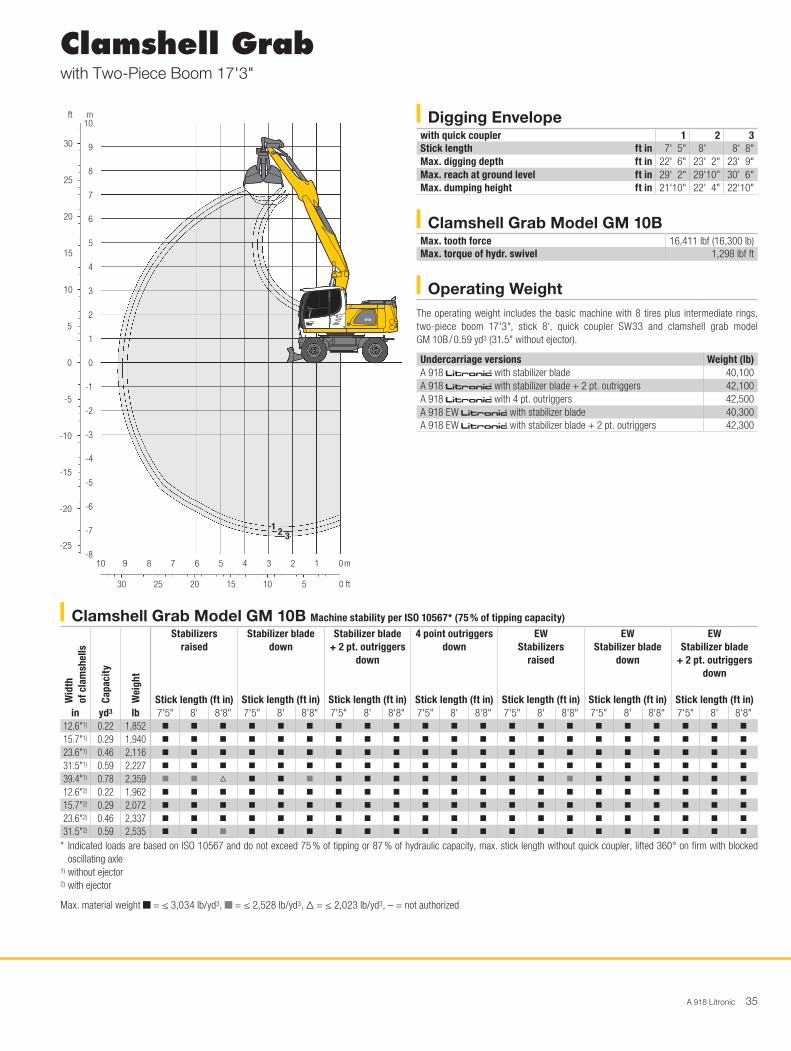
A 918 Litronic 35
Clamshell Grabwith Two-Piece Boom 17'3"
Operating WeightThe operating weight includes the basic machine with 8 tires plus intermediate rings, two-piece boom 17'3", stick 8', quick coupler SW33 and clamshell grab model GM 10B / 0.59 yd3 (31.5" without ejector).
Undercarriage versions Weight (lb)A 918 litronic̀ with stabilizer blade 40,100A 918 litronic̀ with stabilizer blade + 2 pt. outriggers 42,100A 918 litronic̀ with 4 pt. outriggers 42,500A 918 EW litronic̀ with stabilizer blade 40,300A 918 EW litronic̀ with stabilizer blade + 2 pt. outriggers 42,300
Digging Envelopewith quick coupler 1 2 3Stick length ft in 7' 5" 8' 8' 8"Max. digging depth ft in 22' 6" 23' 2" 23' 9"Max. reach at ground level ft in 29' 2" 29'10" 30' 6"Max. dumping height ft in 21'10" 22' 4" 22'10"
Clamshell Grab Model GM 10BMax. tooth force 16,411 lbf (16,300 lb)Max. torque of hydr. swivel 1,298 lbf ft
918
25
30
20
15
10
5
-5
-10
-15
-20
-25
0
8
10
9
1 2 3
H1022
30 25 20 15 10 5
10 8 6 4 2 13579
7
6
5
4
3
2
1
0
-1
-2
-3
-4
-5
-8
-7
-6
0
0
m
ft
mft
Clamshell Grab Model GM 10B Machine stability per ISO 10567* (75 % of tipping capacity)
Wid
th
of c
lam
shel
ls
Capa
city
Wei
ght
Stabilizers raised
Stick length (ft in)
Stabilizer blade down
Stick length (ft in)
Stabilizer blade + 2 pt. outriggers
down
Stick length (ft in)
4 point outriggers down
Stick length (ft in)
EW Stabilizers
raised
Stick length (ft in)
EW Stabilizer blade
down
Stick length (ft in)
EW Stabilizer blade
+ 2 pt. outriggers down
Stick length (ft in)
in yd3 lb 7'5" 8' 8'8" 7'5" 8' 8'8" 7'5" 8' 8'8" 7'5" 8' 8'8" 7'5" 8' 8'8" 7'5" 8' 8'8" 7'5" 8' 8'8"12.6"1) 0.22 1,852 y y y y y y y y y y y y y y y y y y y y y
15.7"1) 0.29 1,940 y y y y y y y y y y y y y y y y y y y y y
23.6"1) 0.46 2,116 y y y y y y y y y y y y y y y y y y y y y
31.5"1) 0.59 2,227 y y y y y y y y y y y y y y y y y y y y y
39.4"1) 0.78 2,359 y y V y y y y y y y y y y y y y y y y y y
12.6"2) 0.22 1,962 y y y y y y y y y y y y y y y y y y y y y
15.7"2) 0.29 2,072 y y y y y y y y y y y y y y y y y y y y y
23.6"2) 0.46 2,337 y y y y y y y y y y y y y y y y y y y y y
31.5"2) 0.59 2,535 y y y y y y y y y y y y y y y y y y y y y
* Indicated loads are based on ISO 10567 and do not exceed 75 % of tipping or 87 % of hydraulic capacity, max. stick length without quick coupler, lifted 360° on firm with blocked oscillating axle
1) without ejector2) with ejector
Max. material weight y = ≤ 3,034 lb/yd3, y = ≤ 2,528 lb/yd3, V = ≤ 2,023 lb/yd3, – = not authorized

36 A 918 Litronic
Clamshell Grabwith Mono Boom 16'5"
Operating WeightThe operating weight includes the basic machine with 8 tires plus intermediate rings, mono boom 16'5", stick 8', quick coupler SW33 and clamshell grab model GM 10B / 0.59 yd3 (31.5" without ejector).
Undercarriage versions Weight (lb)A 918 litronic̀ with stabilizer blade 39,500A 918 litronic̀ with stabilizer blade + 2 pt. outriggers 41,400A 918 litronic̀ with 4 pt. outriggers 41,900A 918 EW litronic̀ with stabilizer blade 39,500A 918 EW litronic̀ with stabilizer blade + 2 pt. outriggers 41,700
Digging Envelopewith quick coupler 1 2 3Stick length ft in 7'5" 8' 8' 8"Max. digging depth ft in 21'6" 22'2" 22'10"Max. reach at ground level ft in 28'1" 28'8" 29' 4"Max. dumping height ft in 19'6" 20' 20' 6"
Clamshell Grab Model GM 10BMax. tooth force 16,411 lbf (16,300 lb)Max. torque of hydr. swivel 1,298 lbf ft
918
25
30
20
15
10
5
-5
-10
-15
-20
-25
0
8
9
1 2 3
H1024
30 25 20 15 10 5
10 8 6 4 2 13579
7
6
5
4
3
2
1
0
-1
-2
-3
-4
-5
-8
-7
-6
0
0
m
ft
mft
Clamshell Grab Model GM 10B Machine stability per ISO 10567* (75 % of tipping capacity)
Wid
th
of c
lam
shel
ls
Capa
city
Wei
ght
Stabilizers raised
Stick length (ft in)
Stabilizer blade down
Stick length (ft in)
Stabilizer blade + 2 pt. outriggers
down
Stick length (ft in)
4 point outriggers down
Stick length (ft in)
EW Stabilizers
raised
Stick length (ft in)
EW Stabilizer blade
down
Stick length (ft in)
EW Stabilizer blade
+ 2 pt. outriggers down
Stick length (ft in)
in yd3 lb 7'5" 8' 8'8" 7'5" 8' 8'8" 7'5" 8' 8'8" 7'5" 8' 8'8" 7'5" 8' 8'8" 7'5" 8' 8'8" 7'5" 8' 8'8"12.6"1) 0.22 1,852 y y y y y y y y y y y y y y y y y y y y y
15.7"1) 0.29 1,940 y y y y y y y y y y y y y y y y y y y y y
23.6"1) 0.46 2,116 y y y y y y y y y y y y y y y y y y y y y
31.5"1) 0.59 2,227 y y y y y y y y y y y y y y y y y y y y y
39.4"1) 0.78 2,359 y y y y y y y y y y y y y y y y y y y y y
12.6"2) 0.22 1,962 y y y y y y y y y y y y y y y y y y y y y
15.7"2) 0.29 2,072 y y y y y y y y y y y y y y y y y y y y y
23.6"2) 0.46 2,337 y y y y y y y y y y y y y y y y y y y y y
31.5"2) 0.59 2,535 y y y y y y y y y y y y y y y y y y y y y
* Indicated loads are based on ISO 10567 and do not exceed 75 % of tipping or 87 % of hydraulic capacity, max. stick length without quick coupler, lifted 360° on firm with blocked oscillating axle
1) without ejector2) with ejector
Max. material weight y = ≤ 3,034 lb/yd3, y = ≤ 2,528 lb/yd3, V = ≤ 2,023 lb/yd3, – = not authorized
A 918 Litronic 37
AttachmentsClamshell Grabs
Clamshell Grab Model GM 8B Machine stability per ISO 10567* (75 % of tipping capacity)
Wid
th
of c
lam
shel
ls
Capa
city
Wei
ght
Stabilizers raised
Stick length (ft in)
Stabilizer blade down
Stick length (ft in)
Stabilizer blade + 2 pt. outriggers
down
Stick length (ft in)
4 point outriggers down
Stick length (ft in)
EW Stabilizers
raised
Stick length (ft in)
EW Stabilizer blade
down
Stick length (ft in)
EW Stabilizer blade
+ 2 pt. outriggers down
Stick length (ft in)
in yd3 lb 7'5" 8' 8'8" 7'5" 8' 8'8" 7'5" 8' 8'8" 7'5" 8' 8'8" 7'5" 8' 8'8" 7'5" 8' 8'8" 7'5" 8' 8'8"Two-piece boom 17'3" 12.6"1) 0.22 1,797 y y y y y y y y y y y y y y y y y y y y y
15.7"1) 0.29 1,896 y y y y y y y y y y y y y y y y y y y y y
23.6"1) 0.39 1,874 y y y y y y y y y y y y y y y y y y y y y
31.5"1) 0.52 1,984 y y y y y y y y y y y y y y y y y y y y y
39.4"1) 3) 1.05 2,205 V V – y V V y y y y y y y V V y y y y y y
12.6"2) 0.22 1,918 y y y y y y y y y y y y y y y y y y y y y
15.7"2) 0.29 2,028 y y y y y y y y y y y y y y y y y y y y y
23.6"2) 0.39 2,072 y y y y y y y y y y y y y y y y y y y y y
31.5"2) 0.52 2,227 y y y y y y y y y y y y y y y y y y y y y
Mono boom 16'5"12.6"1) 0.22 1,797 y y y y y y y y y y y y y y y y y y y y y
15.7"1) 0.29 1,896 y y y y y y y y y y y y y y y y y y y y y
23.6"1) 0.39 1,874 y y y y y y y y y y y y y y y y y y y y y
31.5"1) 0.52 1,984 y y y y y y y y y y y y y y y y y y y y y
39.4"1) 3) 1.05 2,205 y V V y y y y y y y y y y y y y y y y y y
12.6"2) 0.22 1,918 y y y y y y y y y y y y y y y y y y y y y
15.7"2) 0.29 2,028 y y y y y y y y y y y y y y y y y y y y y
23.6"2) 0.39 2,072 y y y y y y y y y y y y y y y y y y y y y
31.5"2) 0.52 2,227 y y y y y y y y y y y y y y y y y y y y y
Offset two-piece boom 16'5"12.6"1) 0.22 1,797 y y y y y y y y y y y y y y y y y y y y y
15.7"1) 0.29 1,896 y y y y y y y y y y y y y y y y y y y y y
23.6"1) 0.39 1,874 y y y y y y y y y y y y y y y y y y y y y
31.5"1) 0.52 1,984 y y y y y y y y y y y y y y y y y y y y y
39.4"1) 3) 1.05 2,205 – – – V V V y y y y y y V V V y y y y y y
12.6"2) 0.22 1,918 y y y y y y y y y y y y y y y y y y y y y
15.7"2) 0.29 2,028 y y y y y y y y y y y y y y y y y y y y y
23.6"2) 0.39 2,072 y y y y y y y y y y y y y y y y y y y y y
31.5"2) 0.52 2,227 y y y y y y y y y y y y y y y y y y y y y
* Indicated loads are based on ISO 10567 and do not exceed 75 % of tipping or 87 % of hydraulic capacity, max. stick length without quick coupler, lifted 360° on firm with blocked oscillating axle
1) without ejector2) with ejector3) Shells for loose material
Max. material weight y = ≤ 3,034 lb/yd3, y = ≤ 2,528 lb/yd3, V = ≤ 2,023 lb/yd3, – = not authorized

38 A 918 Litronic
AttachmentsClamshell Grabs
Clamshell Grab Model GM 10B Machine stability per ISO 10567* (75 % of tipping capacity)
Wid
th
of c
lam
shel
ls
Capa
city
Wei
ght
Stabilizers raised
Stick length (ft in)
Stabilizer blade down
Stick length (ft in)
Stabilizer blade + 2 pt. outriggers
down
Stick length (ft in)
4 point outriggers down
Stick length (ft in)
EW Stabilizers
raised
Stick length (ft in)
EW Stabilizer blade
down
Stick length (ft in)
EW Stabilizer blade
+ 2 pt. outriggers down
Stick length (ft in)
in yd3 lb 7'5" 8' 8'8" 7'5" 8' 8'8" 7'5" 8' 8'8" 7'5" 8' 8'8" 7'5" 8' 8'8" 7'5" 8' 8'8" 7'5" 8' 8'8"Offset two-piece boom 16'5"12.6"1) 0.22 1,852 y y y y y y y y y y y y y y y y y y y y y
15.7"1) 0.29 1,940 y y y y y y y y y y y y y y y y y y y y y
23.6"1) 0.46 2,116 y y y y y y y y y y y y y y y y y y y y y
31.5"1) 0.59 2,227 y y y y y y y y y y y y y y y y y y y y y
39.4"1) 0.78 2,359 y V V y y y y y y y y y y y y y y y y y y
12.6"2) 0.22 1,962 y y y y y y y y y y y y y y y y y y y y y
15.7"2) 0.29 2,072 y y y y y y y y y y y y y y y y y y y y y
23.6"2) 0.46 2,337 y y y y y y y y y y y y y y y y y y y y y
31.5"2) 0.59 2,535 y y y y y y y y y y y y y y y y y y y y y
* Indicated loads are based on ISO 10567 and do not exceed 75 % of tipping or 87 % of hydraulic capacity, max. stick length without quick coupler, lifted 360° on firm with blocked oscillating axle
1) without ejector2) with ejector
Max. material weight y = ≤ 3,034 lb/yd3, y = ≤ 2,528 lb/yd3, V = ≤ 2,023 lb/yd3, – = not authorized

A 918 Litronic 39
AttachmentsDitch Cleaning Buckets / Tilt Buckets
Ditch Cleaning Buckets Machine stability per ISO 10567* (75 % of tipping capacity)
Cutt
ing
wid
th
Capa
city
IS
O 74
511)
Wei
ght
Stabilizers raised
Stick length (ft in)
Stabilizer blade down
Stick length (ft in)
Stabilizer blade + 2 pt. outriggers
down
Stick length (ft in)
4 point outriggers down
Stick length (ft in)
EW Stabilizers
raised
Stick length (ft in)
EW Stabilizer blade
down
Stick length (ft in)
EW Stabilizer blade
+ 2 pt. outriggers down
Stick length (ft in)
in yd3 lb 7'5" 8' 8'8" 7'5" 8' 8'8" 7'5" 8' 8'8" 7'5" 8' 8'8" 7'5" 8' 8'8" 7'5" 8' 8'8" 7'5" 8' 8'8"Two-piece boom 17'3" 59.1"3) 0.65 816 y y y y y y y y y y y y y y y y y y y y y
63.0"2) 0.72 1,433 y y y y y y y y y y y y y y y y y y y y y
63.0"2) 1.05 1,720 y V V y y y y y y y y y y y y y y y y y y
78.7"2) 0.65 1,477 y y y y y y y y y y y y y y y y y y y y y
78.7"3) 0.63 794 y y y y y y y y y y y y y y y y y y y y y
78.7"2) 0.92 1,742 y y y y y y y y y y y y y y y y y y y y y
Mono boom 16'5"59.1"3) 0.65 816 y y y y y y y y y y y y y y y y y y y y y
63.0"2) 0.72 1,433 y y y y y y y y y y y y y y y y y y y y y
63.0"2) 1.05 1,720 y y V y y y y y y y y y y y y y y y y y y
78.7"2) 0.65 1,477 y y y y y y y y y y y y y y y y y y y y y
78.7"3) 0.63 794 y y y y y y y y y y y y y y y y y y y y y
78.7"2) 0.92 1,742 y y y y y y y y y y y y y y y y y y y y y
Offset two-piece boom 16'5"59.1"3) 0.65 816 y y y y y y y y y y y y y y y y y y y y y
63.0"2) 0.72 1,433 y y y y y y y y y y y y y y y y y y y y y
63.0"2) 1.05 1,720 V V V y y V y y y y y y y y V y y y y y y
78.7"2) 0.65 1,477 y y y y y y y y y y y y y y y y y y y y y
78.7"3) 0.63 794 y y y y y y y y y y y y y y y y y y y y y
78.7"2) 0.92 1,742 y V V y y y y y y y y y y y y y y y y y y
Tilt Buckets Machine stability per ISO 10567* (75 % of tipping capacity)
Cutt
ing
wid
th
Capa
city
IS
O 74
511)
Wei
ght
Stabilizers raised
Stick length (ft in)
Stabilizer blade down
Stick length (ft in)
Stabilizer blade + 2 pt. outriggers
down
Stick length (ft in)
4 point outriggers down
Stick length (ft in)
EW Stabilizers
raised
Stick length (ft in)
EW Stabilizer blade
down
Stick length (ft in)
EW Stabilizer blade
+ 2 pt. outriggers down
Stick length (ft in)
in yd3 lb 7'5" 8' 8'8" 7'5" 8' 8'8" 7'5" 8' 8'8" 7'5" 8' 8'8" 7'5" 8' 8'8" 7'5" 8' 8'8" 7'5" 8' 8'8"Two-piece boom 17'3" 59.1"2) 0.78 1,455 y y y y y y y y y y y y y y y y y y y y y
63.0"2) 1.05 1,631 y V V y y y y y y y y y y y y y y y y y y
Mono boom 16'5"59.1"2) 0.78 1,455 y y y y y y y y y y y y y y y y y y y y y
63.0"2) 1.05 1,631 y y y y y y y y y y y y y y y y y y y y y
Offset two-piece boom 16'5"59.1"2) 0.78 1,455 y y y y y y y y y y y y y y y y y y y y y
63.0"2) 1.05 1,631 V V V y y y y y y y y y y y V y y y y y y
* Indicated loads are based on ISO 10567 and do not exceed 75 % of tipping or 87 % of hydraulic capacity, max. stick length without quick coupler, lifted 360° on firm with blocked oscillating axle
1) comparable with SAE (heaped)2) with 2 x 50° rotator3) rigid ditch cleaning bucket
Max. material weight y = ≤ 3,034 lb/yd3, y = ≤ 2,528 lb/yd3, V = ≤ 2,023 lb/yd3, – = not authorized

40 A 918 Litronic
UndercarriageDual-circuit braking system •Lighting trailer coupling +Trailer coupling with bolt, automatic +Digging brake, automatic •Tires (twin tires) Liebherr EM 22 290/90-20 +Individual control outriggers +Travel speed levels (four) •Tilt function of trailer, hydraulic +Mudguards (rear and front) +Load holding valve on each stabilization cylinder •Powershift transmission, semiautomatic •Parking brake, maintenance-free •Tires, variants +Protection for piston rods, stabilizer cylinder +Speeder ** +Undercarriage EW 9' +Tool equipment, extended +Tool box left – lockable •Tool box right – lockable +
Operator’s CabStorage compartment •Cab lights rear, LED +Cab lights front, halogen (under rain cover) •Cab lights front, LED (above rain cover) +Cab lights front, LED (under rain cover) +Exterior mirror, electrical adjustable, with heating +Mechanical hour meters, readable from outside the cab •Roof window made from impact-resistant laminated safety glass +Slewing gear brake Comfort, button on the right joystick +Operator’s seat Standard •Operator’s seat Comfort +Operator’s seat Premium +Driving alarm (acoustic signal is emitted during travel, can be switched ON / OFF) +Fire extinguisher +Front screen made from impact-resistant laminated safety glass – not adjustable +Windscreen retractable (including upper part) •Intermittent windscreen wiper with wiper washer •Cruise control •Rubber floor mat, removable •Dome light •Joystick steering +Coat hook •Automatic air conditioning •Fuel consumption indicator •Electric cooler +Steering wheel, wide version (cost-neutral option) +Steering column adjustable horizontally •LiDAT, vehicle fleet management •Automatic engine shut-down (time adjustable) +Emergency exit rear window •Positioning swing brake +Proportional control •Radio Comfort, control via display with handsfree set +Preparation for radio installation •Rain cover over front window opening •ROPS cab protection •Back-up alarm (acoustic signal is emitted traveling backward, can not be switched off) +Warning beacon on cab, LED +Windows made from impact-resistant laminated safety glass +All tinted windows •Windscreen wiper, roof +Windshield wiper, entire windscreen •Door with sliding window •Top guard +Front guard, adjustable +Right side window and windshield made from laminated safety glass •Sun visor +Sun blind •Auxiliary heating, adjustable (week time switch) +Electronic immobilizer +Cigarette lighter •
UppercarriageUppercarriage right side light, 1 piece, LED +Uppercarriage rear light, 2 pieces, LED +Refuelling system with filling pump +Main battery switch for electrical system •Engine hood with gas spring •Warning beacon on uppercarriage, LED +Service doors, lockable •
Hydraulic SystemShut-off valve between hydraulic tank and pump(s) •Pressure test fittings •Accumulator for controlled lowering of the attachment with the engine shut down •Hydraulic oil filter with integrated microfilter •Liebherr hydraulic oil from – 20 °C to + 40 °C •Liebherr hydraulic oil, biologically degradable +Liebherr hydraulic oil, specially for warm or cold regions +Bypass filter +Switchover high pressure circuit 1 and tipping cylinder +Switchover high pressure circuit 1 and two-piece boom +
Diesel EngineFuel anti-theft device +Liebherr particle filter +Air pre-filter with dust discharge +Preheating fuel +Preheating coolant +Preheating engine oil +
Equipment
A 918 Litronic 41
• = Standard, + = Option* = country-dependent, ** = depending upon the country partially only 25 km/h permitted
Options and / or special attachments, supplied by vendors other than Liebherr, are only to be installed with the knowledge and approval of Liebherr in order to retain warranty.
AttachmentBoom lights, 2 pieces, halogen •Boom lights, 2 pieces, LED +Stick lights, 2 pieces, LED +High pressure circuit incl. unpressurized return line and Tool Control +Electronic lift limitation +Security for hoist cylinder for hydraulic tools +Load lug on stick +Leak oil line, additional for working tools +Liebherr ditch cleaning bucket +Liebherr quick coupler, hydraulic or mechanical +Liebherr tilt bucket +Liebherr tilt rotator +Liebherr sorting grab +Liebherr backhoe bucket +Liebherr tooth system +Liebherr clamshell grab +Medium pressure circuit incl. lines +Mono boom +Pipe fracture safety valves hoist cylinders •Pipe fracture safety valve tipping cylinder +Pipe fracture safety valve stick cylinder •Return line, pressureless (in high pressure circuit option included) +Hose quick coupling at end of stick •Quick coupling system LIKUFIX +Protection for piston rod, tipping cylinder +Protection for bottom side of stick +Tool Control, 10 tool adjustments selectable over the display +Overload warning device •Two-piece boom +Offset two-piece boom +
Complete MachineLubrication
Lubrication undercarriage, manually – decentralized (grease points) •Lubrication undercarriage, manually – centralized (one grease point) +Central lubrication system for uppercarriage and attachment, automatically (without quick coupler and connecting link) * •Central lubrication system, extension for quick coupler +Central lubrication system, extension for connecting link +
Special coatingCustom painting for tools +Special coating, variants +
MonitoringRear view monitoring with camera •Side view monitoring with camera •
Equipment

Wide Product RangeThe Liebherr Group is one of the largest construction equipment manufacturers in the world. Liebherr’s high-value pro ducts and services enjoy a high reputation in many other fields. The wide range includes domestic appliances, aerospace and trans-portation systems, machine tools and maritime cranes.
Exceptional Customer BenefitEvery product line provides a complete range of models in many different versions. With both their technical excellence and acknowledged quality, Liebherr products offer a maximum of customer benefits in practical applications.
State-of-the-art TechnologyTo provide consistent, top quality products, Liebherr attaches great importance to each product area, its components and core technologies. Important modules and components are developed and manufactured in-house, for instance the entire drive and control technology for construction equipment and mining trucks.
Worldwide and IndependentHans Liebherr founded the Liebherr family company in 1949. Since that time, the enterprise has steadily grown to a group of more than 130 companies with over 41,000 employees located on all continents. The corporate headquarters of the Group is Liebherr-International AG in Bulle, Switzerland. The Liebherr family is the sole owner of the company.
www.liebherr.us
The Liebherr Group of Companies
Liebherr Construction Equipment Co. 4100 Chestnut Avenue, Newport News, VA 23607, USA S +1 (757) 245 5251, Fax +1 (757) 928 8701 www.liebherr.us, E-Mail: [email protected] www.facebook.com/LiebherrConstruction
Prin
ted
in G
erm
any
by E
berl
RG
-BK
LH
B/V
F 12
2039
84-0
.5-0
1.17
_enU
S
All
illus
trat
ions
and
dat
a m
ay d
iffer
from
sta
ndar
d eq
uipm
ent.
Sub
ject
to c
hang
e w
ithou
t not
ice.