operation and maintenance - apc · networkair afx 1 operation display interface item function temp...
TRANSCRIPT

NetworkAIR AFX
Operation andMaintenance
AFX65AFX18


Contents
Operation ......................................................................... 1Display Interface . . . . . . . . . . . . . . . . . . . . . . . . . . . . . . . . . . . . . . . . . . 1
Using the Display . . . . . . . . . . . . . . . . . . . . . . . . . . . . . . . . . . . . . . . . . 3Start-up screen . . . . . . . . . . . . . . . . . . . . . . . . . . . . . . . . . . . . . . 3Handling alarms . . . . . . . . . . . . . . . . . . . . . . . . . . . . . . . . . . . . . . 3Display return air conditions status . . . . . . . . . . . . . . . . . . . . . . . 4Display component status . . . . . . . . . . . . . . . . . . . . . . . . . . . . . . 4Display run hours . . . . . . . . . . . . . . . . . . . . . . . . . . . . . . . . . . . . 4View alarm history . . . . . . . . . . . . . . . . . . . . . . . . . . . . . . . . . . . . 5Clear alarm history . . . . . . . . . . . . . . . . . . . . . . . . . . . . . . . . . . . 5
General Setup . . . . . . . . . . . . . . . . . . . . . . . . . . . . . . . . . . . . . . . . . . . . 6Display interface operation . . . . . . . . . . . . . . . . . . . . . . . . . . . . . 6Change the temperature setpoint . . . . . . . . . . . . . . . . . . . . . . . . . 6Change the high and low return temperature alarms . . . . . . . . . . 6Change the humidity setpoint . . . . . . . . . . . . . . . . . . . . . . . . . . . 7Change the humidity high and low alarms . . . . . . . . . . . . . . . . . . 7Remote alarm setup . . . . . . . . . . . . . . . . . . . . . . . . . . . . . . . . . . . 8
Customizing System Settings . . . . . . . . . . . . . . . . . . . . . . . . . . . . . . . 9System setup . . . . . . . . . . . . . . . . . . . . . . . . . . . . . . . . . . . . . . . . 9Passwords . . . . . . . . . . . . . . . . . . . . . . . . . . . . . . . . . . . . . . . . . . 9Temperature units . . . . . . . . . . . . . . . . . . . . . . . . . . . . . . . . . . . 10Communications . . . . . . . . . . . . . . . . . . . . . . . . . . . . . . . . . . . . 10Temperature control . . . . . . . . . . . . . . . . . . . . . . . . . . . . . . . . . 11Humidity control . . . . . . . . . . . . . . . . . . . . . . . . . . . . . . . . . . . . 12Compressor setup . . . . . . . . . . . . . . . . . . . . . . . . . . . . . . . . . . . 13Temperature sensor offset (calibrating AI1) . . . . . . . . . . . . . . . . 14Sensor offsets for AI2 through AI4 . . . . . . . . . . . . . . . . . . . . . . . 14Humidity sensor offset (calibrating AI5) . . . . . . . . . . . . . . . . . . . 15Analog output setup (AO1) . . . . . . . . . . . . . . . . . . . . . . . . . . . . . 16Analog output setup (AO2) . . . . . . . . . . . . . . . . . . . . . . . . . . . . . 16
Resetting the Microprocessor Controller . . . . . . . . . . . . . . . . . . . . . 17
Blower . . . . . . . . . . . . . . . . . . . . . . . . . . . . . . . . . . . . . . . . . . . . . . . . . 18
Cooling Cycle . . . . . . . . . . . . . . . . . . . . . . . . . . . . . . . . . . . . . . . . . . . 19Compressor cooling . . . . . . . . . . . . . . . . . . . . . . . . . . . . . . . . . 19Humidification . . . . . . . . . . . . . . . . . . . . . . . . . . . . . . . . . . . . . . 19Heating cycle . . . . . . . . . . . . . . . . . . . . . . . . . . . . . . . . . . . . . . . 20
NetworkAIR AFX Installation i
Electronic Controls Component Identification . . . . . . . . . . . . . . . . 21Main board components . . . . . . . . . . . . . . . . . . . . . . . . . . . . . . .21Interface diagram . . . . . . . . . . . . . . . . . . . . . . . . . . . . . . . . . . .22Pinout of interface board . . . . . . . . . . . . . . . . . . . . . . . . . . . . . .23Memory . . . . . . . . . . . . . . . . . . . . . . . . . . . . . . . . . . . . . . . . . . .24RS485 serial connection card . . . . . . . . . . . . . . . . . . . . . . . . . . .24Display cable . . . . . . . . . . . . . . . . . . . . . . . . . . . . . . . . . . . . . . .25Temperature/humidity sensor . . . . . . . . . . . . . . . . . . . . . . . . . . .25DIP switch settings . . . . . . . . . . . . . . . . . . . . . . . . . . . . . . . . . .26 . . . . . . . . . . . . . . . . . . . . . . . . . . . . . . . . . . . . . . . . . . . . . . . . .26Gateway . . . . . . . . . . . . . . . . . . . . . . . . . . . . . . . . . . . . . . . . . . .27Redundant group connection box . . . . . . . . . . . . . . . . . . . . . . .27
Configuration Checklist . . . . . . . . . . . . . . . . . . . . . . . . . . . . . . . . . . . 28
Maintenance................................................................... 31Component Control/Safety Adjustments . . . . . . . . . . . . . . . . . . . . . 31
Belt tension . . . . . . . . . . . . . . . . . . . . . . . . . . . . . . . . . . . . . . . .31Overload relay . . . . . . . . . . . . . . . . . . . . . . . . . . . . . . . . . . . . . .32Motor pulley . . . . . . . . . . . . . . . . . . . . . . . . . . . . . . . . . . . . . . . .32Clogged-filter switch . . . . . . . . . . . . . . . . . . . . . . . . . . . . . . . . .33Low air pressure switch . . . . . . . . . . . . . . . . . . . . . . . . . . . . . . .33Air filters . . . . . . . . . . . . . . . . . . . . . . . . . . . . . . . . . . . . . . . . . .34Firestat . . . . . . . . . . . . . . . . . . . . . . . . . . . . . . . . . . . . . . . . . . .35Refrigeration system sight glass . . . . . . . . . . . . . . . . . . . . . . . .35High pressure switch . . . . . . . . . . . . . . . . . . . . . . . . . . . . . . . . .36Flow switch (optional) . . . . . . . . . . . . . . . . . . . . . . . . . . . . . . . .36
Humidifier Procedures . . . . . . . . . . . . . . . . . . . . . . . . . . . . . . . . . . . . 37Humidifier operation . . . . . . . . . . . . . . . . . . . . . . . . . . . . . . . . .37Areas with low water conductivity . . . . . . . . . . . . . . . . . . . . . . .37Humidifier service . . . . . . . . . . . . . . . . . . . . . . . . . . . . . . . . . . .38Remove the steam cylinder . . . . . . . . . . . . . . . . . . . . . . . . . . . .38Remove the humidifier drain valve manifold . . . . . . . . . . . . . . . .41Remove and clean the humidifier drain solenoid . . . . . . . . . . . .42Remove and clean the humidifier fill valve assembly . . . . . . . . .43
System Configurations . . . . . . . . . . . . . . . . . . . . . . . . . . . . . . . . . . . 44Air cooled . . . . . . . . . . . . . . . . . . . . . . . . . . . . . . . . . . . . . . . . .44Water cooled . . . . . . . . . . . . . . . . . . . . . . . . . . . . . . . . . . . . . . .44Glycol system . . . . . . . . . . . . . . . . . . . . . . . . . . . . . . . . . . . . . .45
ii NetworkAIR AFX Installation

System Maintenance Information . . . . . . . . . . . . . . . . . . . . . . . . . . .46Glycol system . . . . . . . . . . . . . . . . . . . . . . . . . . . . . . . . . . . . . . 46Glycol system and water cooled system . . . . . . . . . . . . . . . . . . 46Air cooled system . . . . . . . . . . . . . . . . . . . . . . . . . . . . . . . . . . . 46
Troubleshooting Tables . . . . . . . . . . . . . . . . . . . . . . . . . . . . . . . . . . .47
Monthly Preventive Maintenance. . . . . . . . . . . . . . . . . . . . . . . . . . . .51Environment . . . . . . . . . . . . . . . . . . . . . . . . . . . . . . . . . . . . . . . 51Cleanliness . . . . . . . . . . . . . . . . . . . . . . . . . . . . . . . . . . . . . . . . 52Mechanical . . . . . . . . . . . . . . . . . . . . . . . . . . . . . . . . . . . . . . . . 52Electrical . . . . . . . . . . . . . . . . . . . . . . . . . . . . . . . . . . . . . . . . . . 52
Seasonal Preventive Maintenance. . . . . . . . . . . . . . . . . . . . . . . . . . .53Mechanical . . . . . . . . . . . . . . . . . . . . . . . . . . . . . . . . . . . . . . . . 53Electrical . . . . . . . . . . . . . . . . . . . . . . . . . . . . . . . . . . . . . . . . . . 53
Annual Preventive Maintenance . . . . . . . . . . . . . . . . . . . . . . . . . . . .54Cleanliness . . . . . . . . . . . . . . . . . . . . . . . . . . . . . . . . . . . . . . . . 54
Warranty .........................................................................55Warranty Statement. . . . . . . . . . . . . . . . . . . . . . . . . . . . . . . . . . . . . . .55
APC product covered . . . . . . . . . . . . . . . . . . . . . . . . . . . . . . . . 55Terms of warranty . . . . . . . . . . . . . . . . . . . . . . . . . . . . . . . . . . . 55Non-transferable Warranty extends to first purchaser for use . . 55Assignment of warranties . . . . . . . . . . . . . . . . . . . . . . . . . . . . . 55Drawings, descriptions . . . . . . . . . . . . . . . . . . . . . . . . . . . . . . . 56Warranty claims procedure . . . . . . . . . . . . . . . . . . . . . . . . . . . . 56Exclusions . . . . . . . . . . . . . . . . . . . . . . . . . . . . . . . . . . . . . . . . 56
NetworkAIR AFX Installation iii


Operation
Display InterfaceItem Function
Temp key Allows direct access to the cooling and reheating setpoints, and to their alarm thresholds.
Humid key Allows direct access to the humidification and dehumidification setpoints, and to their alarm thresholds.
Run Hours key Accesses run-hours information including accumulated run-hours on components, run-hour intervals, and hours left before next run-hour alarm.
Status key Displays incoming air conditions and operational status.
Liquid Crystal Display (LCD)
The 4-line by 20-character alphanumeric display shows unit operating conditions, any present alarms, and user-programmable configuration prompts.
Alarm History key Accesses past (cue/number) alarms.3
Help key Provides information to navigate screens.
Network key Displays the number of units on the redundant network and their addresses.
Enter key • Moves the cursor within the menu screen.• Clears displayed alarms.• After modifying a parameter, repeatedly pressing the Enter key will return the cursor
to the upper left corner where it must be located to accept the change.
Down Arrow key • Turns to the previous page within a menu.• Decreases a selected control parameter in small increments. When pressed and held,
decreases the parameter in large increments.
NetworkAIR AFX 1

Operation: Display Interface
Up Arrow key • Turns to the next page within a menu.• Increases a selected control parameter in small increments. When pressed and held,
increases the parameter in large increments.
Alarm key Immediately displays the first alarm. An illuminated red LED in the center of the key indicates the presence of an alarm.
On/Off key • Starts the unit locally when it is in the System Off mode.• Stops the unit locally when it is in the Fan On mode (indicated by an illuminated
green LED in the center of the key).
Blank key Returns the display screen to the home page.
Config key Allows access to the following Technician menus:• Custom Setup• Remote Alarm Setup
Special key Allows you to set the time and date.
Item Function
2 NetworkAIR AFX

Using the Display
Start-up screenWhen power is applied, the display momentarily shows the unit type and date of the program:
Handling alarmsAfter the start up screen has displayed, the red LED in the center of the alarm key illuminates if an alarm has been activated. If no action is taken, the display will cycle through the following screens:
To clear alarms:
1. Press the alarm key.
2. Press the key to scroll through the alarms.
3. Press Enter to clear the alarms.
60 seconds of key inactivity will return the display to the default screen (screen 1) . You may change the first line of the default screen to personalize the designation of the unit with up to 10 digits. See “Communications” on page 10 for more information.
Note: If the alarm returns after clearing, the alarm condition still exists.
1 2 3
NetworkAIR AFX 3

Operation: Using the Display
Display return air conditions statusPress the Status key to display the default screen, which reports the temperature and humidity and indicates whether the system is ON or OFF.If the system is ON, the bottom line will display Fan ON after first showing Initial delay.... If the system is in the dehumidification mode, the display will also show Dehumidify.
Display component statusPress the Status Key, then press 1 time.Top line:
– As shown, the unit is OFF.– Fan ON = the unit is running.
• Second line:– C1-OFF = The compressor is OFF.– C1-ON = The compressor is running. If the unit has two stages of cooling, the C2 status will be
displayed as well.– C1-PMDN = A compressor is pumping down.
• Last line:– Heat and humidifier status.
Display run hours1. Press the Run Hours key.
•The digital output for the component is shown on the first line.•The component name and run hours is shown on the second line.•The alarm interval is shown on the third line.
To modify Alarm set, press Enter 1 time. Use or to set the hours as desired (0000-9999). After modifying you must press Enter repeatedly until the cursor returns to the upper left corner and the changes are accepted.
•The remaining time left before the next alarm occurs is shown on the fourth line.
2. Press to display the next run time alarm and settings.
Note: You cannot change the following status screens.
Note: The screens shown are examples only. Your screens may be different, depending upon the system, options, and status.
4 NetworkAIR AFX

Operation: Using the Display
View alarm historyThe last twenty alarm occurrences are tracked and displayed as a list. Each list will store up to ten different simultaneous alarms.
1. Press the Alarm History key.
2. Press Enter to display the most recent alarm list.
•The first line shows the date, time in 24-hour format, and sequential list number. In this example, the alarm occurred on January 1 at 1:15 pm, and is the third list in the sequence (L:03).
•The second line shows the return temperature and humidity level at which the alarm occurred.
•The third line displays the alarm type.
3. To view the next list, press Enter. Press or to loop through all the lists.
Clear alarm history
You might want to clear the alarm history from the controller, for example, after you change or update the program, or overhaul your equipment.
1. Press the Alarm History key to display the alarm history screen.
2. Press (the blank key) to move the cursor above the word Key.
3. Press the Help key to reset the history. When the screen displays again, the history has been reset.
Note: As alarms occur, the list number is incremented until the maximum number of 20 is reached. After list number 20 is reached, the next alarm will overwrite the oldest list.
Caution: After the history is cleared from memory, it cannot be retrieved.
NetworkAIR AFX 5
General Setup
Display interface operation• Changes will NOT be accepted until you repeatedly press Enter, moving the cursor to the upper
left corner of the screen.
• Once the cursor is located in the upper left corner of the screen, the setting can take effect. You may now press another key and perform a different programming function, or in 60 seconds, the display will revert to the default screen.
• When using or to change settings, a single press of the key will change the setting to the next value. Press and hold the key to scroll quickly.
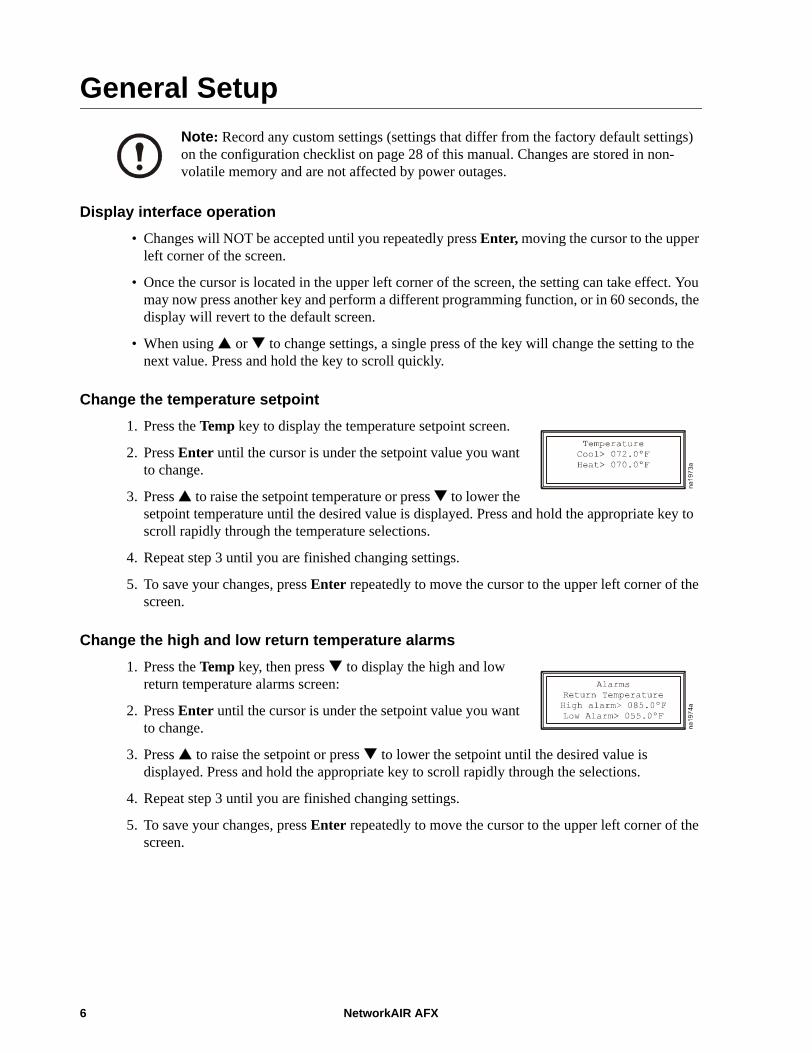
Change the temperature setpoint1. Press the Temp key to display the temperature setpoint screen.
2. Press Enter until the cursor is under the setpoint value you want to change.
3. Press to raise the setpoint temperature or press to lower the setpoint temperature until the desired value is displayed. Press and hold the appropriate key to scroll rapidly through the temperature selections.
4. Repeat step 3 until you are finished changing settings.
5. To save your changes, press Enter repeatedly to move the cursor to the upper left corner of the screen.
Change the high and low return temperature alarms1. Press the Temp key, then press to display the high and low
return temperature alarms screen:
2. Press Enter until the cursor is under the setpoint value you want to change.
3. Press to raise the setpoint or press to lower the setpoint until the desired value is displayed. Press and hold the appropriate key to scroll rapidly through the selections.
4. Repeat step 3 until you are finished changing settings.
5. To save your changes, press Enter repeatedly to move the cursor to the upper left corner of the screen.
Note: Record any custom settings (settings that differ from the factory default settings) on the configuration checklist on page 28 of this manual. Changes are stored in non-volatile memory and are not affected by power outages.
6 NetworkAIR AFX

Operation: General Setup
Change the humidity setpoint1. Press the Humid key.
2. Press Enter until the cursor is under the value you want to change.
3. Press to raise the setpoint or press to lower the setpoint until the desired value is displayed. Press and hold the appropriate key to scroll rapidly through the setpoint selections.
4. Repeat step 3 until you are finished changing settings.
5. To save your changes, press Enter repeatedly to move the cursor to the upper left corner of the screen.
Change the humidity high and low alarms1. Press the Humid key, then press to display the humidity alarms
screen.
2. Press Enter until the cursor is under the value you want to change.
3. Press to raise the setpoint or press to lower the setpoint until the desired value is displayed. Press and hold the appropriate key to scroll rapidly through the setpoint selections.
4. Repeat step 3 until you are finished changing settings.
5. To save your changes, press Enter repeatedly to move the cursor to the upper left corner of the screen.
NetworkAIR AFX 7

Operation: General Setup
Remote alarm setup1. Press the Config key to display the technician menu.
2. Press Enter until the cursor is on the “Remote alarm setup” line.
3. Press to display the remote alarm setup screen.
4. Press or to scroll through the following alarms:
Each alarm may be set with its COM (Common Option) ON or OFF:
• COM set to ON: When an alarm occurs, the unit will display the alarm locally (at the unit) and change the state of the Common Alarm Dry Contacts (see unit wiring).
• COM set to OFF: When an alarm occurs, the unit will still display the alarm locally, but the Common Alarm Dry Contacts will not change state.
Each alarm may be set with its XFR (Transfer Option) ON or OFF:
• XFR set to ON: When an alarm occurs, the unit will display the alarm locally, shut down, and transfer operation to a standby unit in the same Redundant Unit Group Network, if one exists.
• XFR set to OFF: When an alarm occurs, the unit will display the alarm locally and continue running. Fatal alarms, such as Fire or Smoke are the exception. The unit will shut down and will not attempt to transfer operation to any other unit.
5. Press Enter to select each alarm’s COM or XFR setting and press or to set each to ON or OFF.
6. To save your changes, press Enter repeatedly to move the cursor to the upper left corner of the screen.
EEPROM Fail Low Temp C2 High PSI C1 LP
Airflow High Hum Water Detect Water Flow
Ret Hi Temp Low Hum Humidifier
Ret Low Temp C1 High PSI Smoke Detector
Hi Temp C2 Low PSI Filter
Note: Factory default setting on all alarms are: COM set to ON and XFR set to OFF.
8 NetworkAIR AFX

Customizing System Settings
System setup1. Press the Config key to display the Technician Menu.
2. Press Enter repeatedly until the cursor is on the Custom setup line.
3. Press to display the first page of the setup screen.
The Fan delay and Mode delay allow a wide range of settings to stagger the startup of multiple units to prevent power overloads or allow external dampers to open.
a. Fan delay is adjustable to 999 seconds and delays the amount of time before the blower runs when the on/off key is pressed from the Keypad OFF mode. The default is factory set to zero (no delay).
b. Mode delay values are adjustable from 1 to 999 seconds. The factory set default is 11 seconds. This setting delays the first mode of operation after the blower starts.
The Alarm buzzer is factory set to OFF. When set to OFF, the alarm sounds momentarily during startup, but not during an alarm condition. When set to ON, the alarm sounds whenever an alarm condition exists.
4. Press Enter repeatedly to move the cursor to the desired item.
5. Press or to change the setting.
6. To save your changes, press Enter repeatedly to move the cursor to the upper left corner of the screen.
PasswordsThe two levels of passwords are factory set to all zeros, allowing unlimited access to all programming functions without password prompts. The level 1 password allows access only to the temperature and humidity setpoints. The level 2 password allows access to the setpoints and the setup menus.
1. Press the Config key to display the technician menu.
2. Press Enter twice until the cursor is on the Custom setup line.
3. Press repeatedly until the password screen is displayed.
4. Press Enter repeatedly until the cursor is below the desired password level.
5. Press or to change the password.
NetworkAIR AFX 9

Operation: Customizing System Settings
6. When you finish your changes to the first password, press Enter repeatedly until the cursor is below the next password level.
7. Press or to change the password.
8. To save your changes, press Enter repeatedly to move the cursor to the upper left corner of the screen...
Temperature unitsThe temperature can be displayed and controlled in either Fahrenheit or Celsius.
1. Press the Config key to display the technician menu.
2. Press Enter twice until the cursor is on the Custom setup line.
3. Press until the temperature screen is displayed.
4. Press Enter repeatedly until the cursor is on the Units line.
5. Press or to change the temperature units.
6. To save your changes, press Enter repeatedly to move the cursor to the upper left corner of the screen.
CommunicationsYou can set the following values:
• Unit name (up to 10 digits)• Network ID number (1 - 200)• Communications baud rate (1200 - 19200)
1. Press the Config key to display the technician menu.
2. Press Enter twice until the cursor is on the Custom setup line.
3. Press repeatedly until the communications screen is displayed.
4. Press Enter repeatedly until the cursor is under the specific digit of the setting you want to change.
5. Press or to change the digit.
6. Repeat steps 4 and 5 until all changes are made.
7. To save your changes, press Enter repeatedly to move the cursor to the upper left corner of the screen.
Note: The level 1 password will not become effective until a password is entered for level 2.
Note: Call the Customer Support telephone number for your region (located on the back of the manual) for technical support if you forget your passwords.
10 NetworkAIR AFX
Operation: Customizing System Settings
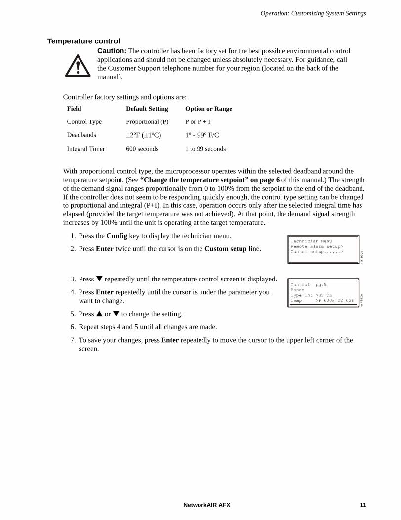
Temperature control
Controller factory settings and options are:
With proportional control type, the microprocessor operates within the selected deadband around the temperature setpoint. (See “Change the temperature setpoint” on page 6 of this manual.) The strength of the demand signal ranges proportionally from 0 to 100% from the setpoint to the end of the deadband. If the controller does not seem to be responding quickly enough, the control type setting can be changed to proportional and integral (P+I). In this case, operation occurs only after the selected integral time has elapsed (provided the target temperature was not achieved). At that point, the demand signal strength increases by 100% until the unit is operating at the target temperature.
1. Press the Config key to display the technician menu.
2. Press Enter twice until the cursor is on the Custom setup line.
3. Press repeatedly until the temperature control screen is displayed.
4. Press Enter repeatedly until the cursor is under the parameter you want to change.
5. Press or to change the setting.
6. Repeat steps 4 and 5 until all changes are made.
7. To save your changes, press Enter repeatedly to move the cursor to the upper left corner of the screen.
Caution: The controller has been factory set for the best possible environmental control applications and should not be changed unless absolutely necessary. For guidance, call the Customer Support telephone number for your region (located on the back of the manual).
Field Default Setting Option or Range
Control Type Proportional (P) P or P + I
Deadbands ±2ºF (±1ºC) 1º - 99º F/C
Integral Timer 600 seconds 1 to 99 seconds
NetworkAIR AFX 11

Operation: Customizing System Settings
Humidity control
Controller factory settings and options are:
With proportional control type, the microprocessor operates within the selected deadband around the humidity setpoint. (See “Change the humidity setpoint” on page 7 of this manual.) The strength of the demand signal ranges proportionally from 0 to 100% from the setpoint to the end of the band. If the controller does not seem to be responding quickly enough, the control type setting can be changed to proportional and integral (P+I). In this case, operation occurs only after the selected integral time has elapsed (provided the target humidity was not achieved). At that point, the demand signal strength increases by 100% until the unit is operating at the target humidity.
1. Press the Config key to display the technician menu.
2. Press Enter twice until the cursor is on the Custom setup line.
3. Press repeatedly until the humidity control screen is displayed.
4. Press Enter repeatedly until the cursor is under the parameter you want to change.
5. Press or to change to the desired setting.
6. Repeat steps 4 and 5 until all changes are made.
7. To save your changes, press Enter repeatedly to move the cursor to the upper left corner of the screen.
Caution: The controller has been factory set for the best possible environmental control applications and should not be changed unless absolutely necessary. For guidance, call the Customer Support telephone number for your region (located on the back of the manual).
Field Default Setting Option or Range
Control Type Proportional (P) P or P + I
Deadbands ±5% RH 1% - 99% RH
Integral Timer 600 seconds 1 to 99 seconds
12 NetworkAIR AFX
Operation: Customizing System Settings
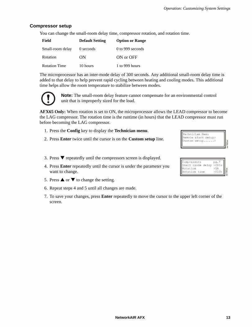
Compressor setupYou can change the small-room delay time, compressor rotation, and rotation time.
The microprocessor has an inter-mode delay of 300 seconds. Any additional small-room delay time is added to that delay to help prevent rapid cycling between heating and cooling modes. This additional time helps allow the room temperature to stabilize between modes.
AFX65 Only: When rotation is set to ON, the microprocessor allows the LEAD compressor to become the LAG compressor. The rotation time is the runtime (in hours) that the LEAD compressor must run before becoming the LAG compressor.
1. Press the Config key to display the Technician menu.
2. Press Enter twice until the cursor is on the Custom setup line.
3. Press repeatedly until the compressors screen is displayed.
4. Press Enter repeatedly until the cursor is under the parameter you want to change.
5. Press or to change the setting.
6. Repeat steps 4 and 5 until all changes are made.
7. To save your changes, press Enter repeatedly to move the cursor to the upper left corner of the screen.
Field Default Setting Option or Range
Small-room delay 0 seconds 0 to 999 seconds
Rotation ON ON or OFF
Rotation Time 10 hours 1 to 999 hours
Note: The small-room delay feature cannot compensate for an environmental control unit that is improperly sized for the load.
NetworkAIR AFX 13
Operation: Customizing System Settings
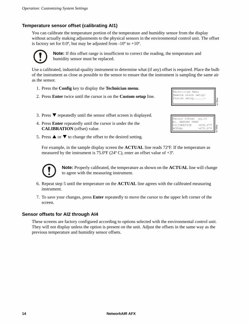
Temperature sensor offset (calibrating AI1)You can calibrate the temperature portion of the temperature and humidity sensor from the display without actually making adjustments to the physical sensors in the environmental control unit. The offset is factory set for 0.0º, but may be adjusted from -10º to +10º.
Use a calibrated, industrial-quality instrument to determine what (if any) offset is required. Place the bulb of the instrument as close as possible to the sensor to ensure that the instrument is sampling the same air as the sensor.
1. Press the Config key to display the Technician menu.
2. Press Enter twice until the cursor is on the Custom setup line.
3. Press repeatedly until the sensor offset screen is displayed.
4. Press Enter repeatedly until the cursor is under the the CALIBRATION (offset) value.
5. Press or to change the offset to the desired setting.
For example, in the sample display screen the ACTUAL line reads 72ºF. If the temperature as measured by the instrument is 75.0ºF (24º C), enter an offset value of +3º.
6. Repeat step 5 until the temperature on the ACTUAL line agrees with the calibrated measuring instrument.
7. To save your changes, press Enter repeatedly to move the cursor to the upper left corner of the screen.
Sensor offsets for AI2 through AI4These screens are factory configured according to options selected with the environmental control unit. They will not display unless the option is present on the unit. Adjust the offsets in the same way as the previous temperature and humidity sensor offsets.
Note: If this offset range is insufficient to correct the reading, the temperature and humidity sensor must be replaced.
Note: Properly calibrated, the temperature as shown on the ACTUAL line will change to agree with the measuring instrument.
14 NetworkAIR AFX
Operation: Customizing System Settings
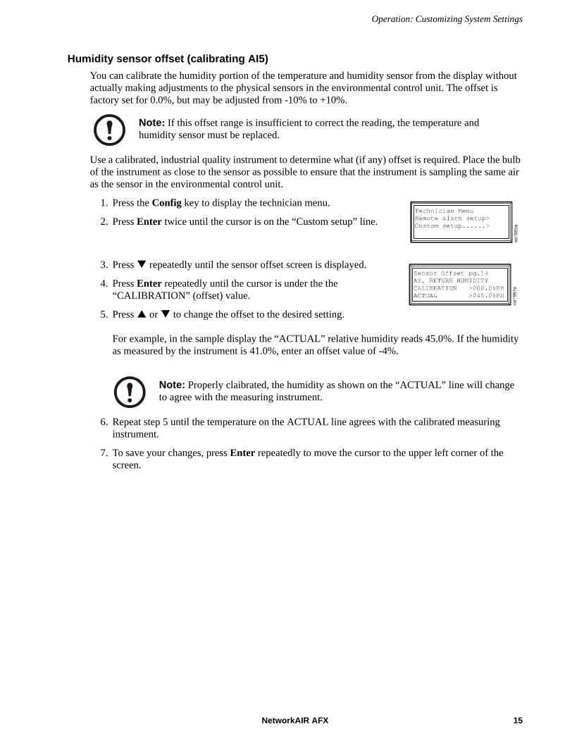
Humidity sensor offset (calibrating AI5)You can calibrate the humidity portion of the temperature and humidity sensor from the display without actually making adjustments to the physical sensors in the environmental control unit. The offset is factory set for 0.0%, but may be adjusted from -10% to +10%.
Use a calibrated, industrial quality instrument to determine what (if any) offset is required. Place the bulb of the instrument as close to the sensor as possible to ensure that the instrument is sampling the same air as the sensor in the environmental control unit.
1. Press the Config key to display the technician menu.
2. Press Enter twice until the cursor is on the “Custom setup” line.
3. Press repeatedly until the sensor offset screen is displayed.
4. Press Enter repeatedly until the cursor is under the the “CALIBRATION” (offset) value.
5. Press or to change the offset to the desired setting.
For example, in the sample display the “ACTUAL” relative humidity reads 45.0%. If the humidity as measured by the instrument is 41.0%, enter an offset value of -4%.
6. Repeat step 5 until the temperature on the ACTUAL line agrees with the calibrated measuring instrument.
7. To save your changes, press Enter repeatedly to move the cursor to the upper left corner of the screen.
Note: If this offset range is insufficient to correct the reading, the temperature and humidity sensor must be replaced.
Note: Properly claibrated, the humidity as shown on the “ACTUAL” line will change to agree with the measuring instrument.
NetworkAIR AFX 15

Operation: Customizing System Settings
Analog output setup (AO1)
Some options of the environmental control unit use analog voltage outputs. You can configure the starting and ending voltages, and choose either the direct-acting or reverse-acting mode.Factory settings:Line 2 displays the name of the optional unit (CG Damper, Humidifier, COOL, or HEAT). If you have none of these options, NA is displayed.
1. Press the Config key to display the technician menu.
2. Press Enter twice until the cursor is on the Custom setup line.
3. Press repeatedly until the sensor analog output screen is displayed.
4. Press Enter repeatedly until the cursor is under the the value you want to change.
5. Press or to change the value.
6. Repeat steps 4 and 5 until all values have been changed.
7. To save your changes, press Enter repeatedly to move the cursor to the upper left corner of the screen.
Analog output setup (AO2)
Note: If the display reads N/A and the system is utlilizing analog output at start-up, call the Customer Support number for your region (see the back cover of this manual) for technical assistance.
Field Default Setting Range or Option
Low voltage 06.0 VDC 0.0 to 10.0 VDC
High voltage 09.0 VDC 0.0 to 10.0 VDC
Mode DIR DIR or REV
Note: If the display reads N/A and the system is utlilizing analog output at start-up, call the Customer Support number for your region (see the back cover of this manual) for technical assistance.
See Analog output setup (A01) on page 15 of this manual for instructions on Analog output number 2 setup.
16 NetworkAIR AFX
Resetting the Microprocessor ControllerThe controller stores all setup information in non-volatile memory;
• factory defaults
• user-defined values
• information specific to any options supplied with the unit
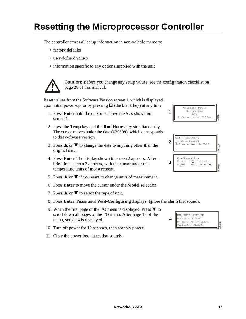
Reset values from the Software Version screen 1, which is displayed upon intial power-up, or by pressing (the blank key) at any time.
1. Press Enter until the cursor is above the S as shown on screen 1.
2. Press the Temp key and the Run Hours key simultaneously. The cursor moves under the date (020599), which corresponds to this software version.
3. Press or to change the date to anything other than the original date.
4. Press Enter. The display shown in screen 2 appears. After a brief time, screen 3 appears, with the cursor under the temperature units of measurement.
5. Press or if you want to change units of measurement.
6. Press Enter to move the cursor under the Model selection.
7. Press or to select the type of unit.
8. Press Enter. Pause until Wait-Configuring displays. Ignore the alarm that sounds.
9. When the first page of the I/O menu is displayed. Press to scroll down all pages of the I/O menu. After page 13 of the menu, screen 4 is displayed.
10. Turn off power for 10 seconds, then reapply power.
11. Clear the power loss alarm that sounds.
Caution: Before you change any setup values, see the configuration checklist on page 28 of this manual.
1
2
3
4
NetworkAIR AFX 17

BlowerThe blower will run continuously under the following conditions:
• Correct current (24 volts) is present on DI 5 (Enable)
• The start-up delay timer is not running
• The unit is not in STANDBY
• No FIRE or SMOKE alarms exist
• The unit has not been placed in the STOP mode (either locally or remotely)
• Overloads are not tripped
Caution: The blower will not run during an AIRFLOW ALARM condition.
18 NetworkAIR AFX

Cooling Cycle
Compressor cooling
AFX65: In cooling mode, compressors are engaged incrementally with increasing demand. The lead compressor stage activates when the return air temperature reaches the setpoint plus 50% of the deadband. For example, if the setpoint is 80º F and the deadband is 4º, the lead compressor is activated at 82ºF. As the return air temperature rises to the setpoint plus 99% of the deadband (84º F in the example), the lag compressor is activated.
When the return air temperature falls to the setpoint plus 20% of the deadband (approximately 81ºF, 27ºC), the lag compressor shuts off, provided its minimum-on timer has expired. If the return air temperature drops to the setpoint plus 1% of the deadband (80ºF, 26ºC), the lead compressor shuts off provided its minimum-on timer has expired.
AFX18: In cooling mode, the compressor is engaged when the return air temperature reaches the setpoint plus 50% of the deadband. For example, if the setpoint is 80ºF (26ºC) and the deadband is 4º, the compressor is activated at 82ºF (28ºC).
When the return air temperature falls to the setpoint plus 20% of the deadband (approximately 81ºF, 27ºC), the compressor shuts off.
Humidification
When enabled, humidification occurs when the relative humidity is less than the humidity setpoint minus the humidity deadband. The digital humidity output turns on and remains on until the humidity reaches the humidity setpoint. If the analog humidifier control is enabled, the analog output can be used to control a proportional humidifier. The output is at the minimum voltage when the humidity is at or above the humidification setpoint. The output increases proportionally as the humidity drops from the humidity setpoint.
To set deadbands, see “Temperature control” on page 11 of this manual.
To set deadbands, see “Temperature control” on page 11 of this manual.
To configure humidifier settings, see “Humidity control” on page 12 of this manual.
NetworkAIR AFX 19

Operation: Cooling Cycle
Heating cycle
Electric heating occurs when the heaters are enabled and the return air temperature is below its heating setpoint minus the deadband. Three stages of heating are available to maintain the return air temperature above its heating setpoint.
The percentage of heating is shown in the center of the display.During either dehumidification mode, air is reheated after it is cooled in order to remove moisture.
To set up dehumidification, see “Change the humidity setpoint” on page 7 of this manual.
To configure the heating setpoint, see “Change the temperature setpoint” on page 6 of this manual.
Stage 1 Stage 2 Percentage of total available heat output
OFF ON 33%
ON OFF 66%
ON ON 100%
20 NetworkAIR AFX
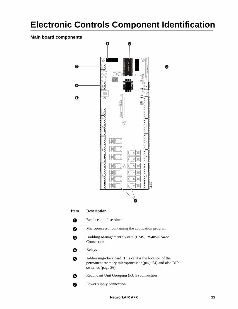
Electronic Controls Component IdentificationMain board components
Item Description
Replaceable fuse block
Microprocessor containing the application program
Building Management System (BMS) RS485/RS422 Connection
Relays
Addressing/clock card. This card is the location of the permanent memory microprocessor (page 24) and also DIP switches (page 26)
Redundant Unit Grouping (RUG) connection
Power supply connection
NetworkAIR AFX 21
Operation: Electronic Controls Component Identification
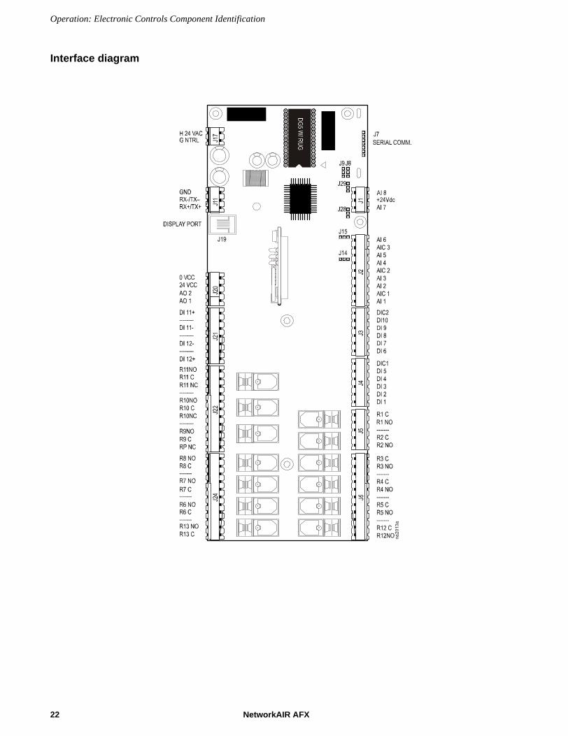
Interface diagram
22 NetworkAIR AFX

Operation: Electronic Controls Component Identification
Pinout of interface board
Pin Levels Default Signal DefinitionDI 1 Digital Input Low= Airflow AlarmDI 2 Digital Input High = Clogged Filter AlarmDI 3 Digital Input High = Water Detector AlarmDI 4 Digital Input Low = Compressor 1 L P, HWF AlarmDI 5 Digital Input High = System EnableDI 6 Digital Input Low = Compressor 2 L P, Door AlarmDI 7 Digital Input Low = Water F12, Water F13 AlarmDI 8 Digital Input High = Firestat AlarmDI 9 Digital Input High = Smoke Detector AlarmDI 10 Digital Input High = Humidifier Freeze, Compressor Lockout, Condensate Pump AlarmDI 11 Digital Input Low = Compressor 1 High Pressure AlarmDI 12 Digital Input Low = Compressor 2 High Pressure AlarmAI 1 NTC Input Return Temperature sensorAI 2 NTC Input Supply TemperatureAI 3 NTC Input Not UsedAI 4 NTC Input Temperature 2AI 5* Analog Input 0 to 1 volt Return Humidity sensorAI 6* Analog Input Not UsedAI 7** Analog Input Remote TempAI 8** Analog Input Remote HumidityDO 1 Digital Output BlowerDO 2 Digital Output Electric Heat Stage 1 or Heat Valve OpenDO 3 Digital Output Electric Heat Stage 2 or Heat Valve CloseDO 4 Digital Output HumidiferDO 5 Digital Output Compressor 1 Liquid LineDO 6 Digital Output Compressor 1 ContactorDO 7 Digital Output Compressor 2 Liquid Line, Fan low speed, Hot Gas bypassDO 8 Digital Output Compressor 2 ContactorDO 9 Digital Output Unloader 1, Hot Gas 1, CL Valve openDO 10 Digital Output DEH/HG2, CL valve close, Unloader 2DO 11 Digital Output Common AlarmDO 12 Digital Output Not UsedDO 13 Digital Output Not UsedAO1 Analog Output Cool, Heat, HumidifierAO2 Analog Output Cool, Heat, HumidifierNOTE: * Analog inputs 5 and 6 (AI 5 and AI 6) are selectable for either 0-1 volt or 4-20 ma inputs. * Jumper 2 and 3 for 0-1 volt or 1 and 2 for 4-20 ma. See the Interface Board diagram on page 22.* J14 controls AI 5* J15 controls AI 6** Analog inputs 7 and 8 (AI 7 and AI 8) are 4-20 ma inputs only.
NetworkAIR AFX 23

Operation: Electronic Controls Component Identification
Memory
Location and removal.
RS485 serial connection card
Item Description
Main Board
Microprocessor containing application program )
Addressing/clock card
Microprocessor containing permanent memory
24 NetworkAIR AFX

Operation: Electronic Controls Component Identification
Display cable
Temperature/humidity sensor
Item Description Item Description
Wire, White Wire, Yellow
Wire, Black Wire, Blue
Wire, Red RJ11 modular plug, (Quantity of 2)
Wire, Green Flat cable, 6-conductor, 24-guage, 500 ft maximum
NetworkAIR AFX 25

Operation: Electronic Controls Component Identification
DIP switch settings
1. The location of the display board DIP switches.
2. The location of the DIP switches on addressing/clock card. The addressing/clock card is located on the main board. See Main Board on page 21.
26 NetworkAIR AFX

Operation: Electronic Controls Component Identification
Gateway
Redundant group connection box
NetworkAIR AFX 27

Configuration Checklist• Numbers in parentheses are Celsius
• Ranges for temperatures are scale independent (ºF or ºC).
• The given ranges do not imply that the unit will function properly over all of the values.
PARAMETER DEFAULT RANGE SETTINGStart Up Delay 000 seconds 0 to 600 secondsFan Delay 11 seconds 0 to 600 secondsCool Setpoint 72.0º F (22.0º) 12.0º to 95.0º (-11º to 35º)Cool Band 2.0º F (1.0º) 1.0º to 15.0ºReturn Temperature Offset 00.0º F (00.0º) -20.0º to + 20.0ºDX Stages 2 0 to 2Small Room Delay 000 seconds 0 to 999 secondsPump Down OFF ON or OFFMinimum DX Off Time 300 seconds 180 to 999 secondsMinimum DX On Time 300 seconds 180 to 999 secondsReturn Temperature Sensor Alarm Common ON ON or OFFReturn Temperature Sensor Alarm Transfer ON ON or OFFDX Lead/Lag ON ON or OFFLead/Lag Switch Time 10 hours 1 to 999 hoursHeat Setpoint 70.0º F (21.0º) 0º to 85.0º (-17º to 29º)Heat Band 2.0º F (1.0º) 1.0º to 15.0ºHeat Type ELECTRIC ELECTRIC or VALVEElectric Heat Stages 2 0 - 2Humidifier Control ENABLED ENABLED or
DISABLEDDehumidification Control ENABLED ENABLED or
DISABLEDHumidification Setpoint 45.0 % RH 10.0 to 85.0 % RHDehumidification Setpoint 55.0 % RH 10.0 to 95.0 % RHHumidification Band 5.0 % RH 1.0 to 30.0 % RHDehumidification Band 5.0 % RH 1.0 to 30.0 % RHHumidity Sensor Offset 00.0 % -20.0 % to +20.0 %Analog Humidity Start Voltage 00.0 V 0.0 to +10.0 VAnalog Humidity Span Voltage 10.0 V -10.0 to +10.0 VAnalog Humidity Offset Voltage 0.0 V -2.0 to +2.0 VReturn Humidity Sensor Alarm Common ON ON or OFFReturn Humidity Sensor Alarm Transfer OFF ON or OFFAirflow Alarm Common ON ON or OFF Airflow Alarm Transfer OFF ON or OFF Airflow Alarm Closure OFF ON or OFF Airflow Alarm Enable ON ON or OFF Airflow Alarm Delay 10 seconds 10-600 secondsClogged Filter Alarm Common ON ON or OFF Clogged Filter Alarm Transfer OFF ON or OFF
28 NetworkAIR AFX

Operation: Configuration Checklist
Clogged Filter Alarm Closure ON ON or OFF Clogged Filter Alarm Enable ON ON or OFF Water Detector Alarm Common ON ON or OFF Water Detector Alarm Transfer OFF ON or OFF Water Detector Alarm Closure ON ON or OFF Water Detector Alarm Enable ON ON or OFF Comp. 1 Low Pressure Alarm Common ON ON or OFF Comp. 1 Low Pressure Alarm Transfer OFF ON or OFF Comp. 1 Low Pressure Alarm Closure OFF ON or OFF Comp. 1 Low Pressure Alarm Enable ON ON or OFF Comp. 2 Low Pressure Alarm Common ON ON or OFF Comp. 2 Low Pressure Alarm Transfer OFF ON or OFF Comp. 2 Low Pressure Alarm Closure OFF ON or OFF Comp. 2 Low Pressure Alarm Enable ON ON or OFF Water Flow Alarm Common ON ON or OFF Water Flow Alarm Transfer OFF ON or OFF Water Flow Alarm Closure OFF ON or OFF Water Flow Alarm Enable ON ON or OFF FireStat Alarm Common ON ON or OFF FireStat Alarm Transfer OFF ON or OFF FireStat Alarm Closure ON ON or OFF FireStat Alarm Enable ON ON or OFF Smoke Detector Alarm Common ON ON or OFF Smoke Detector Alarm Transfer OFF ON or OFF Smoke Detector Alarm Closure ON ON or OFF Smoke Detector Alarm Enable ON ON or OFF Comp. 1 High Pressure Alarm Common ON ON or OFF Comp. 1 High Pressure Alarm Transfer OFF ON or OFF Comp. 1 High Pressure Alarm Closure OFF ON or OFF Comp. 1 High Pressure Alarm Enable ON ON or OFF Comp. 2 High Pressure Alarm Common ON ON or OFF Comp. 2 High Pressure Alarm Transfer OFF ON or OFF Comp. 2 High Pressure Alarm Closure OFF ON or OFF Comp. 2 High Pressure Alarm Enable ON ON or OFF Comp. 1 Pump Down Alarm Common ON ON or OFF Comp. 1 Pump Down Alarm Transfer OFF ON or OFF Comp. 2 Pump Down Alarm Common ON ON or OFF Comp. 2 Pump Down Alarm Transfer OFF ON or OFF High Return Temp. Alarm Common ON ON or OFF High Return Temp. Alarm Transfer OFF ON or OFF High Return Temp. Alarm Enable ON ON or OFF High Return Temp. Alarm At 85.0º F (30.0º) 0º to 100.0ºHigh Return Temp. Alarm Delay 300 seconds 1 to 600 secondsLow Return Temp. Alarm Common ON ON or OFFLow Return Temp. Alarm Transfer OFF ON or OFFLow Return Temp. Alarm Enable ON ON or OFF
PARAMETER DEFAULT RANGE SETTING
NetworkAIR AFX 29

Operation: Configuration Checklist
Low Return Temp. Alarm At 55.0º F (13º) 0.0º to 100.0ºLow Return Temp. Alarm Delay 300 seconds 1 to 600 secondsHigh Humidity Alarm Common ON ON or OFFHigh Humidity Alarm Transfer OFF ON or OFFHigh Humidity Alarm Enable ON ON or OFF High Humidity Alarm At 85.0% RH 0 to 100.0% RH High Humidity Alarm Delay 300 seconds 1 to 600 seconds Low Humidity Alarm Common ON ON or OFF Low Humidity Alarm Transfer OFF ON or OFF Low Humidity Alarm Enable ON ON or OFF Low Humidity Alarm At 30.0% RH 0 to 100.0% RH Low Humidity Alarm Delay 300 seconds 1 to 600 seconds Power Loss Alarm ON ON or OFF Blower Run Time Alarm OFF ON or OFF Blower Run Time Alarm Every 1000 hours 0 to 9999 Comp. 1 Run Time Alarm OFF ON or OFF Comp. 1 Run Time Alarm Every 1000 hours 0 to 9999 Comp. 2 Run Time Alarm OFF ON or OFF Comp. 2 Run Time Alarm Every 1000 hours 0 to 9999 Humidifier Run Time Alarm OFF ON or OFF Humidifier Run Time Alarm Every 1000 hours 0 to 9999 Setpoint Password 0000 0000-9999 Service Password 0000 0000-9999 Supervisor Address 00 00-100
PARAMETER DEFAULT RANGE SETTING
30 NetworkAIR AFX

Maintenance
Component Control/Safety AdjustmentsBelt tensionWarning: Perform Lockout/Tagout procedures on the equipment being serviced. Failure to remove power before servicing this equipment could result in serious injury or death.
The blower motor is mounted on an adjustable base. Increase or decrease belt tension by raising or lowering the base.
A properly adjusted belt will deflect about 3/4 to 1 inch (19 to 25 mm) per foot (300 mm) of span between the blower and motor pulleys when firmly pressed. Lock the belt in position after making adjustments.
Note: APC recommends using only trained APC service personnel when servicing this equipment.
Caution: Too much tension shortens bearing, shaft and belt life.
NetworkAIR AFX 31
Maintenance: Component Control/Safety Adjustments
For quiet operation, the belt should be as loose as possible without causing slippage. Slippage can cause belt noise, insufficient airflow, or both. If the smaller pulley is noticeably warmer than the larger pully, the likely cause is belt slippage. Tighten the belt slightly. Do not test temperature while pulleys are turning.
Readjust belt tension if the variable-speed pulley setting is changed or if the belt is replaced.
Overload relayThe blower motor starter has an adjustable overload relay. Set the adjustment dial to correspond to the full load amperes (FLA) on the blower motor. The overload has a manual reset button to prevent the motor from cycling on the overload switch.
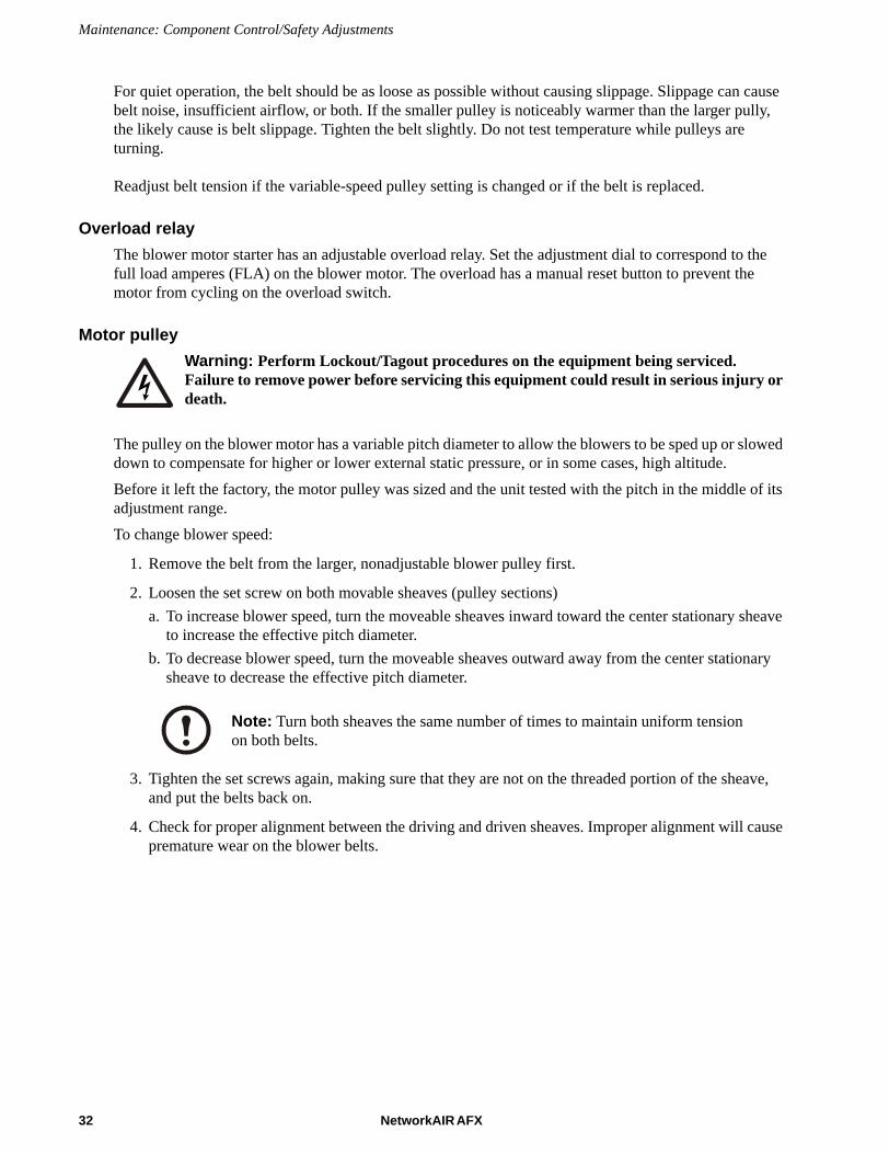
Motor pulleyWarning: Perform Lockout/Tagout procedures on the equipment being serviced. Failure to remove power before servicing this equipment could result in serious injury or death.
The pulley on the blower motor has a variable pitch diameter to allow the blowers to be sped up or slowed down to compensate for higher or lower external static pressure, or in some cases, high altitude. Before it left the factory, the motor pulley was sized and the unit tested with the pitch in the middle of its adjustment range.To change blower speed:
1. Remove the belt from the larger, nonadjustable blower pulley first.
2. Loosen the set screw on both movable sheaves (pulley sections)a. To increase blower speed, turn the moveable sheaves inward toward the center stationary sheave
to increase the effective pitch diameter. b. To decrease blower speed, turn the moveable sheaves outward away from the center stationary
sheave to decrease the effective pitch diameter.
3. Tighten the set screws again, making sure that they are not on the threaded portion of the sheave, and put the belts back on.
4. Check for proper alignment between the driving and driven sheaves. Improper alignment will cause premature wear on the blower belts.
Note: Turn both sheaves the same number of times to maintain uniform tension on both belts.
32 NetworkAIR AFX

Maintenance: Component Control/Safety Adjustments
Clogged-filter switch
The clogged-filter switch senses the air pressure drop across the filters. When the pressure drop is too high because of dirty filters, the switch closes and causes an alarm. The clogged filter switch has been set at the factory for approximately 1.0 inch of Water Column pressure drop across the filters. Check the setting at unit start-up. Cover one-third of the filter area and increase or decrease the clogged filter switch sensitivity so that the switch closes when one third of the filter area is blocked.
Low air pressure switchThe unit uses an APD (air pressure differential) switch to sense airflow loss through the unit. The APD is factory set to close at 0.2 inches of Water Column. The pressure setting is adjustable by turning the adjustment screw clockwise to increase and counterclockwise to decrease the setting.
Note: The following procedure can only be performed using new, clean filters.
NetworkAIR AFX 33
Maintenance: Component Control/Safety Adjustments
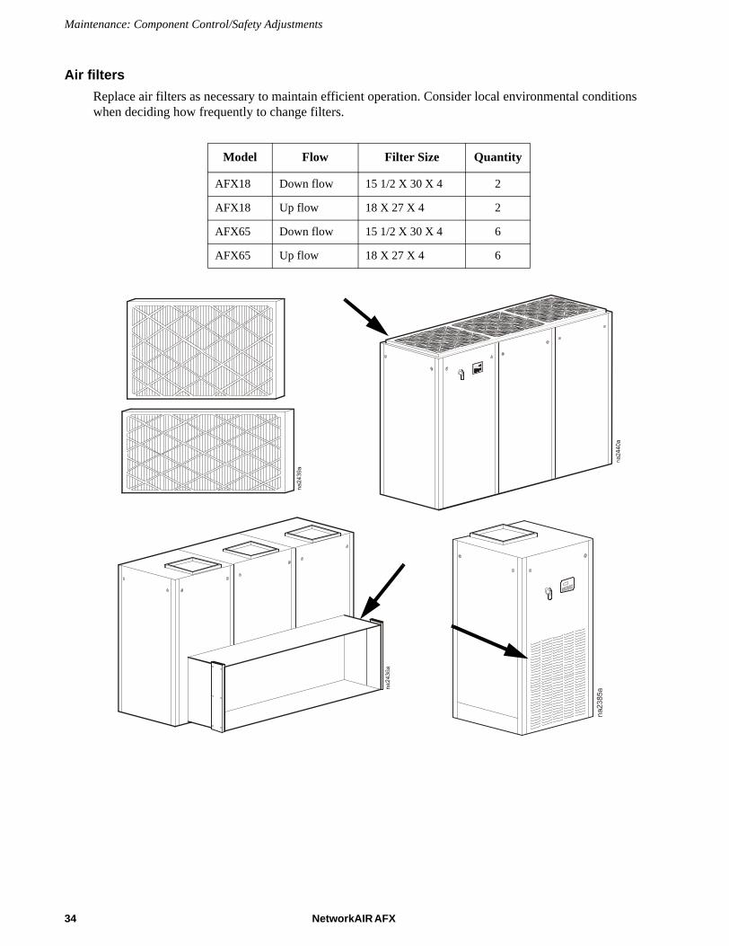
Air filtersReplace air filters as necessary to maintain efficient operation. Consider local environmental conditions when deciding how frequently to change filters.
Model Flow Filter Size Quantity
AFX18 Down flow 15 1/2 X 30 X 4 2
AFX18 Up flow 18 X 27 X 4 2
AFX65 Down flow 15 1/2 X 30 X 4 6
AFX65 Up flow 18 X 27 X 4 6
34 NetworkAIR AFX

Maintenance: Component Control/Safety Adjustments
FirestatThe firestat heat response device used in this unit has a manual reset and an adjustable temperature setting . The firestat is factory set prior to shipment to trip when temperatures above 125°F are detected. If the firestat is tripped, an alarm sounds and the unit is shut down. To reset the firestat, press the silver button on the device. The location of the firestat depends on the unit model and options.
Refrigeration system sight glassThe refrigeration sight glass indicates liquid refrigerant flow and the presence of moisture. Bubbles in the sight glass indicate a shortage of refrigerant or a restriction in the liquid line. The moisture indicator changes from green to yellow when moisture is present in the system.
NetworkAIR AFX 35
Maintenance: Component Control/Safety Adjustments
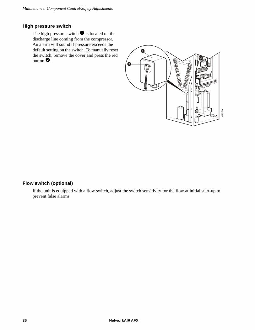
High pressure switchThe high pressure switch is located on the discharge line coming from the compressor. An alarm will sound if pressure exceeds the default setting on the switch. To manually reset the switch, remove the cover and press the red button .
Flow switch (optional)If the unit is equipped with a flow switch, adjust the switch sensitivity for the flow at initial start-up to prevent false alarms.
36 NetworkAIR AFX

Humidifier Procedures
Humidifier operationWhen the humidistat is activated, the cylinder fills to 110% of the Full Load Amperage (F.L.A.) or to the top of the cylinder, whichever occurs first. If it reaches 110% F.L.A., the water heats and boils away to 90% F.L.A. The humidistat concentrates conductive minerals in the cylinder so that a smaller volume of water is required to produce the rated steam output. Achieving the correct concentration of minerals extends the life of the disposable cylinder by minimizing electrode coverage.A water level that is too high usually indicates that the concentration of minerals in the cyliinder needs to be reduced so the unit adjusts the fill and drain valves to dilute the water. When 90% F.L.A. is reached, the fill valve opens refilling the cylinder to 110% F.L.A. If the water level rises too high, the drain valve will also come on. 03214560132251
Areas with low water conductivityYou can accelerate the normalization process by artificially increasing water conductivity. Dissolve one-half teaspoon of salt in a cup of water. Add it to the humidifier at the fill cup during a fill cycle.
Item Description
Steam hose
Cylinder
Electrodes
Drain valve
Drain pan
Drain canal
Strainer
Fill valve
Inlet chamber
Fill cup
Fill chamber
Water overflow chamber
NetworkAIR AFX 37

Maintenance: Humidifier Procedures
Humidifier service Warning: Perform Lockout/Tagout procedures on the equipment being serviced. Failure to remove power before servicing this equipment could result in serious injury or death.
Warning: Burn hazard. The humidifier cylinder and drain lines may contain hot water. Let the humidifier cool before servicing.
1. Toggle the humidifier switch to the DRAIN position.
Note: Wait 30 seconds to allow the humidifier cylinder to drain completely.
2. Remove power from the equipment at the mains.
3. Open the equipment door.
4. Verify that power is off.
Remove the steam cylinder
Warning: Burn hazard. The cylinder may be hot. Let it cool before touching it, or use protective gloves.
Note: Replace the disposable steam cylinder at the end of its cylinder life. Cylinder life depends on water condition and humidifier usage.
1. The power wires to the cylinder are attached to cylinder plugs to the electrode pins on top of the cylinder. Pull these plugs vertically off the pins.
38 NetworkAIR AFX

Maintenance: Humidifier Procedures
2. Using a standard screwdriver, loosen the steam hose clamp and pull the steam hose off vertically.
3. Release the steam cylinder lock belt.
NetworkAIR AFX 39

Maintenance: Humidifier Procedures
4. Lift the steam cylinder up and out of the drain fitting.
5. Carefully remove the O-ring retainer and O-ring, Clean any debris or scaling from the drain fitting.
6. Install a new steam cylinder by reversing the removal procedure.
Note: Do not damage or discard the O-ring retainer and O-ring that are in the drain fitting.
40 NetworkAIR AFX

Maintenance: Humidifier Procedures
Remove the humidifier drain valve manifold
Note: Clean the drain valve manifold yearly, or more often if water quality is poor.
1. With the cylinder removed, disconnect the wires from the drain valve solenoid.
2. Remove the hose clamp and disconnect the drain valve hose from the drain valve assembly.
3. Remove the screw securing the drain canal to the drain valve body.
4. Remove the gasket and drain canal, including the drain hose, from the bottom of the humidifier frame.
NetworkAIR AFX 41

Maintenance: Humidifier Procedures
Remove and clean the humidifier drain solenoidTo clean the drain manifold and solenoid, remove the drain valve solenoid.
Note: Clean the drain solenoid plunger yearly, or more often in installations with poor water quality.
1. Unscrew the solenoid from the valve manifold.
2. Use water and a soft brush to clean the plunger of debris and deposits.
3. Flush the drain opening on the manifold with water and use a soft brush to clear it of debris and deposits.
Note: Replace the manifold if the drain is blocked and cannot be cleaned.
4. Clean any debris or scaling in the drain fitting.
Note: Do not damage or discard the O-ring retainer and O-ring that are in the drain fitting.
Note: Replace the solenoid if the spring and core are damaged or cannot be cleaned.
42 NetworkAIR AFX

Maintenance: Humidifier Procedures
Remove and clean the humidifier fill valve assembly1.Remove the wire connections from the fill valve assembly.
2.Remove the fill hose and clamp from the top of the fill valve assembly.
3.Remove the hard water line from the outside of the humidifier frame.
4.Remove the two screws holding the fill valve assembly to the humidifier frame.
5.Use a soft brush to clean the filtering screen on the inlet side of the fill valve assembly.
6.Install a new humidifier fill valve assembly by reversing the removal procedure.
Note: In installations with poor water quality it may be necessary to cleanthe inlet screen frequently.
NetworkAIR AFX 43
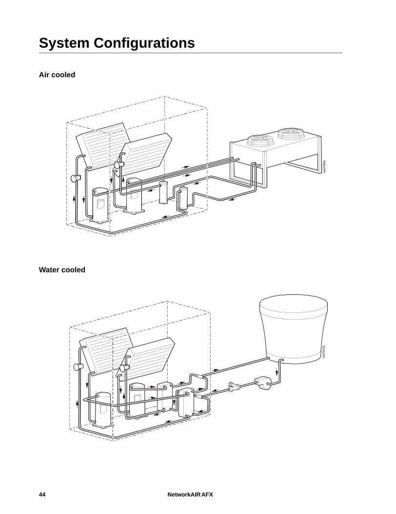
System Configurations
Air cooled
Water cooled
44 NetworkAIR AFX

Maintenance: System Configurations
Glycol system
NetworkAIR AFX 45
System Maintenance Information
Glycol system
Filling. 1.Use a pre-mixed solution of 40% ethylene glycol and 60% water. Add corrosion inhibitors when mixing to prevent build up of contaminants in the system.
Glycol system and water cooled system
Cleaning. A 20-mesh strainer collects particles in the system to keep them from circulating. Water quality will determine the how often the cleaning should occur. Check the strainer regularly until you can establish an appropriate schedule.Mineral build-up on the heat exchanger plates can cause a decrease in thermal transfer. Clean-in-place (CIP) using a solution of trisodium phosphate and water. Flush the solution with water after cleaning to remove the solution. Water quality will determine your cleaning frequency.
Air cooled system
Leak check. Test all refrigerant connections for leaks before charging the system.
1. Attach a refrigerant gauge manifold and slowly add a small amount of refrigerant vapor to raise the system pressure to 2 psig.
2. After the initial trace gas has been added, pressurize the system to 100 psig with dry nitrogen.
3. Repair any leaks.
4. Pressurize the system again to 100 psig to double-check all joints.
Vacuum check. After performing the leak check, use a vacuum pump to evacuate the system.
1. Attach a micron gauge at a place on the system away from the vacuum pump connections.
2. Start the vacuum pump and pull the system down to 500 microns.
3. Isolate the vacuum pump.
4. Allow the system to sit for 2 hours, and monitor the micron gauge. The micron guage reading should not rise above 2000 microns. If a reading higher than 2000 microns is found, there is a leak or residual moisture in the system. Perform another vacuum procedure or another leak check on the system.
5. Break the vacuum with dry refrigerant.
Charging. The system can now be fully charged. Follow standard HVAC charging practices. The nominal superheat is 15 degrees Fahrenheit and the nominal subcooling 10 degrees Fahrenheit.
Compressor oil. Refrigerant carries some oil from the compressor as it circulates. Long runs of piping carry more refrigerant, which could deplete the compressor oil and cause failure. Check the oil level and add additional oil to the compressor if your system contains more than 30 pounds of refrigerant.
46 NetworkAIR AFX
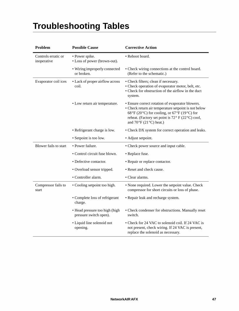
Troubleshooting Tables
Problem Possible Cause Corrective Action
Controls erratic or inoperative
• Power spike.• Loss of power (brown-out).
• Reboot board.
• Wiring improperly connected or broken.
• Check wiring connections at the control board. (Refer to the schematic.)
Evaporator coil ices • Lack of proper airflow across coil.
• Check filters; clean if necessary.• Check operation of evaporator motor, belt, etc.• Check for obstruction of the airflow in the duct
system.
• Low return air temperature. • Ensure correct rotation of evaporator blowers.• Check return air temperature setpoint is not below
68°F (20°C) for cooling, or 67°F (19°C) for reheat. (Factory set point is 72° F (22°C) cool, and 70°F (21°C) heat.)
• Refrigerant charge is low. • Check DX system for correct operation and leaks.
• Setpoint is too low. • Adjust setpoint.
Blower fails to start • Power failure. • Check power source and input cable.
• Control circuit fuse blown. • Replace fuse.
• Defective contactor. • Repair or replace contactor.
• Overload sensor tripped. • Reset and check cause.
• Controller alarm. • Clear alarms.
Compressor fails to start
• Cooling setpoint too high. • None required. Lower the setpoint value. Check compressor for short circuits or loss of phase.
• Complete loss of refrigerant charge.
• Repair leak and recharge system.
• Head pressure too high (high pressure switch open).
• Check condenser for obstructions. Manually reset switch.
• Liquid line solenoid not opening.
• Check for 24 VAC to solenoid coil. If 24 VAC is not present, check wiring. If 24 VAC is present, replace the solenoid as necessary.
NetworkAIR AFX 47

Maintenance: Troubleshooting Tables
Compressor short cycles
• Low line voltage is causing compressor electric motor to overheat.
• Check power source for the cause of variation in line voltage.
• Dirty or icy evaporator (reduced air flow).
• Defrost and/or clean the evaporator.
• Lack of refrigerant (bubbly sight glass).
• Repair leak and recharge system.
• Light load. • Configure controller for light load.
• Defective LP switch. • Check and, if necessary, replace.
Noisy compressor • Expansion valve is stuck in the open position (abnormally cold suction line).
• Ensure feeler bulb is tight on the suction line. Check operation and superheat.
• Low oil. • Check oil charge.
• Worn or scarred compressor bearings (excessive knocking).
• Replace compressor.
• Incorrect amperage. • Check nameplate for proper amperage. Compare to operating amperage.
System short of capacity (noticable pressure drop)
• Flash gas in liquid refrigerant line (bubbly sight glass).
• Repair leak and recharge system.
• Expansion valve stuck or possibly obstructed (short cycling or continuous running).
• Remove and clean valve. Replace it, if necessary.
• Clogged drier-strainer (feels cold).
• Replace drier-strainer.
• Ice or dirt on evaporator coil (excessively warm air from evaporator blower). See Evaporator coil ices, page 47.
• Defrost and, if necessary, clean.
Problem Possible Cause Corrective Action
48 NetworkAIR AFX

Maintenance: Troubleshooting Tables
Suction pressure too low
• Flash gas in liquid refrigerant line (bubbly sight glass).
• Repair leak and recharge system.
• Clogged drier strainer (strainer feels cold).
• Replace.
• Obstructed expansion valve (loss of capacity).
• Repair or replace valve.
• Loss of fluid within expansion valve (erratic valve response).
• Replace valve and feeler bulb assembly.
• Lack of refrigerant (bubbly sight glass).
• Repair leak and recharge system.
• Dirty air filters (clogged filter light is on).
• Clean air filters.
• Clogged or icy coil. • Defrost or clean.
Humidifier inoperative
• Water not connected. • Connect and turn on water.
• Electrical connections loose. • Tighten electrical connections.
• Humidifier circuit breaker open.
• Check for short circuit. Replace circuit breaker if necessary.
Reheat elements inoperative
• Overheat switch actuated. • Reset switch and check that elements are operating..
• Circuit breaker open. • Check for short circuit; replace circuit breaker if necessary.
• Thermostat set too low. • Adjust thermostat to an appropriate higher setting.
• Thermal line in heater open. • Replace line.
Water carryover • Insufficient air quantity over the evaporator coil.
• Check that the amperage to the fan is within nameplate AMPS limits. Remove discharge air restrictions. Clean filters.
• Dirty coil. • Clean the coil.
• Excessive air. • Reduce CFM.
Controller fails to start.
• No power to controller. • Check control line.• Check for blown fuses.• Check that the control transformer is tapped
properly.
Problem Possible Cause Corrective Action
NetworkAIR AFX 49

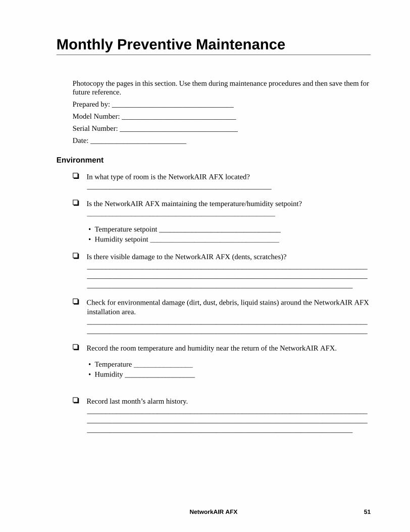
Monthly Preventive Maintenance
Photocopy the pages in this section. Use them during maintenance procedures and then save them for future reference.Prepared by: _________________________________Model Number: _______________________________Serial Number: ________________________________Date: __________________________
Environment
In what type of room is the NetworkAIR AFX located? __________________________________________________
Is the NetworkAIR AFX maintaining the temperature/humidity setpoint? ___________________________________________________
• Temperature setpoint _________________________________ • Humidity setpoint ___________________________________
Is there visible damage to the NetworkAIR AFX (dents, scratches)? ________________________________________________________________________________________________________________________________________________________________________________________________________________________________
Check for environmental damage (dirt, dust, debris, liquid stains) around the NetworkAIR AFX installation area. ________________________________________________________________________________________________________________________________________________________
Record the room temperature and humidity near the return of the NetworkAIR AFX.
• Temperature ________________ • Humidity ___________________
Record last month’s alarm history. ________________________________________________________________________________________________________________________________________________________________________________________________________________________________
NetworkAIR AFX 51
Monthly Preventive Maintenance
Cleanliness
Check that filters are clean and in place.
Check that the condensate drain is open.
Check the condition of the drain pan, remove any accumulation of debris in the pan, and clean the pan.
Check that the humidifier cylinder replacement light is not on, and verify proper operation of the humidifier.
Clean the inside of the unit as necessary.
Mechanical
Check that drive belts are in good condition and that belt tension is correct.
Check that the blower bearing/shaft assembly turns freely.
Check the conformance of the unit to temperature and humidity setpoints.
Ensure heater operation.
Electrical
Check electrical components, ensure correct current draws, and ensure that connections are securely tightened.
Check the microprocessor configuration.
Check the microprocessor for any alarm.
52 NetworkAIR AFX
Seasonal Preventive Maintenance
* Perform all the monthly preventive maintenance items and the items below.Prepared by: _________________________________Model Number: ______________________________Serial Number: _______________________________Date: ____________________
Mechanical
Check fans, and check drive components.
Check belts. Service or replace them, if necessary.
Check refrigerant pressures.
Clean condensers.
Flush coolant (in water/glycol-cooled units) and check strainers (in water-cooled, and in water/glycol-cooled units).
Electrical
Check electrical components for loose wire connections.
Check that all electrical contacts are in good condition.
NetworkAIR AFX 53

Annual Preventive Maintenance
* Perform all the monthly and seasonal preventive maintenance items and the items below.Prepared by: _________________________________Model Number: ______________________________Serial Number: _______________________________Date: ____________________
Cleanliness
Thoroughly check the system, and clean the interior of the unit.
Clean the cooling coil.
54 NetworkAIR AFX
Warranty
Warranty StatementThe limited warranty provided by American Power Conversion Corporation (APC) in this Statement of Limited Factory Warranty applies only to Products you purchase for your commercial or industrial use in the ordinary course of your business.
LIMITED FACTORY WARRANTY
APC product coveredAPC Network AIR AFX Precision Air Conditioning Unit
Terms of warrantyAPC warrants that the Product shall be free from defects in materials and workmanship for a period of one (1) year from the date of start-up when APC authorized service personnel performed the start-up of the Product, or a maximum of 18 months from the date of Product shipment from APC, when APC authorized service personnel have not performed the start-up of the Product (“Warranty Period”). In the event that the Product fails to meet the foregoing warranty, APC shall repair or replace any defective parts, such repair or replacement to be without charge for on-site labor and travel if APC authorized personnel have conducted start-up of the Product. An APC Start-Up Service must be performed/completed by APC authorized service personnel or replacement of defective parts only will be covered. APC shall have no liability and no obligation to repair the installed Product if non-authorized personnel performed the start-up and such start-up caused the Product to be defective. Any parts furnished under this warranty may be new or factory-remanufactured. This warranty does not cover circuit breaker resetting, loss of refrigerant, consumables, or preventative maintenance items. Repair or replacement of a defective product or part thereof does not extend the original warranty period.
Non-transferable Warranty extends to first purchaser for useThis Warranty is extended to the first person, firm, association or corporation (herein referred to by You or Your) for whom the APC Product specified herein has been purchased. This Warranty is not transferable or assignable without the prior written permission of APC.
Assignment of warrantiesAPC will assign to you any warranties which are made by manufacturers and suppliers of components of the APC Product and which are assignable. Any such warranties are assigned AS IS and APC makes no representations as to the effectiveness or extent of such warranties, assumes NO RESPONSIBILITY for any matters which may be warranted by such manufacturers or suppliers and extends no coverage under this Warranty to such components.
NetworkAIR AFX 55

Warranty: Warranty Statement
Drawings, descriptionsAPC warrants for the Warranty Period and on the terms of the Warranty set forth herein that the APC Product will substantially conform to the descriptions contained in the APC Official Published Specifications or any of the drawings certified and agreed to by an authorized APC representative, if applicable thereto (Specifications). It is understood that the Specifications are not warranties of performance and not warranties of fitness for a particular purpose.
Warranty claims procedureTo obtain service under Warranty, contact APC Worldwide Customer Support at the number on the back cover of this manual. You will need the model number of the Product, the serial number, and the date purchased. A technician will ask you to describe the problem. If it is determined that the Product will need to be returned to APC you must obtain a returned material authorization (RMA) number from APC Worldwide Customer Support. Products that must be returned must have the RMA number marked on the outside of the package, and be returned with transportation charges prepaid. If it is determined by APC Worldwide Customer Support that on-site repair of the Product is allowed, APC will arrange to have APC authorized service personnel dispatched to the Product location to repair or replace the Product at the discretion of APC.
ExclusionsAPC shall not be liable under the Warranty if its testing and examination discloses that the alleged defect in the product does not exist or was caused by your or any third person’s misuse, negligence, improper installation or testing, unauthorized attempts to repair or modify, or any other cause beyond the range of the intended use, or by accident, fire, lightning or other hazard.THERE ARE NO WARRANTIES, EXPRESSED OR IMPLIED, BY OPERATION OF LAW OR OTHERWISE, OF PRODUCTS SOLD, SERVICED OR FURNISHED UNDER THIS AGREEMENT OR IN CONNECTION HEREWITH. APC DISCLAIMS ALL IMPLIED WARRANTIES OF MERCHANTABILITY, SATISFACTION AND FITNESS FOR A PARTICULAR PURPOSE. THE APC EXPRESS WARRANTIES WILL NOT BE ENLARGED, DIMINISHED, OR AFFECTED BY AND NO OBLIGATION OR LIABILITY WILL ARISE OUT OF APC RENDERING TECHNICAL OR OTHER ADVICE OR SERVICE IN CONNECTION WITH THE PRODUCTS. THE FOREGOING WARRANTIES AND REMEDIES ARE EXCLUSIVE AND IN LIEU OF ALL OTHER WARRANTIES AND REMEDIES. THE WARRANTIES SET FORTH ABOVE, CONSTITUTE SOLE LIABILITY OF APC AND YOUR EXCLUSIVE REMEDY FOR ANY BREACH OF SUCH WARRANTIES. THE WARRANTIES EXTEND ONLY TO YOU AND ARE NOT EXTENDED TO ANY THIRD PARTIES.IN NO EVENT SHALL APC, ITS OFFICERS, DIRECTORS, AFFILIATES OR EMPLOYEES BE LIABLE FOR ANY FORM OF INDIRECT, SPECIAL, CONSEQUENTIAL OR PUNITIVE DAMAGES ARISING OUT OF THE USE, SERVICE OR INSTALLATION OF THE PRODUCTS, WHETHER SUCH DAMAGES ARISE IN CONTRACT OR TORT, IRRESPECTIVE OF FAULT, NEGLIGENCE OR STRICT LIABILITY OR WHETHER APC HAS BEEN ADVISED IN ADVANCE OF THE POSSIBILITY OF SUCH DAMAGE.
56 NetworkAIR AFX


12/2006990-2298*990-2298*
APC Worldwide Customer SupportCustomer support for this or any other APC product is available at no charge in any of the following ways:
• Visit the APC Web site to access documents in the APC Knowledge Base and to submit customer support requests.– www.apc.com (Corporate Headquarters)
Connect to localized APC Web sites for specific countries, each of which provides customer support information.
– www.apc.com/support/Global support searching APC Knowledge Base and using e-support.
• Contact an APC Customer Support center by telephone or e-mail.– Regional centers
– Local, country-specific centers: go to www.apc.com/support/contact for contact information.
Contact the APC representative or other distributor from whom you purchased your APC product for information on how to obtain local customer support.
Direct InfraStruXure Customer Support Line
(1)(877)537-0607 (toll free)
APC headquarters U.S., Canada
(1)(800)800-4272 (toll free)
Latin America (1)(401)789-5735 (USA)
Europe, Middle East, Africa
(353)(91)702000 (Ireland)
Japan (0) 35434-2021
Australia, New Zealand, South Pacific area
(61) (2) 9955 9366 (Australia)
Entire contents copyright 2006 American Power Conversion Corporation. All rights reserved. Reproduction in whole or in part without permission is prohibited. APC, the APC logo, NetworkAIR and InfraStruXure are trademarks of American Power Conversion Corporation. All other trademarks, product
names, and corporate names are the property of their respective owners and are used for informational purposes only.