operation and maintenance manual 6irq9ae · electric lift pump the ecm controls the electric lift...
TRANSCRIPT

1
Operation and Maintenance Manual 6IRQ9AE
Revision 1 June 2003

2
THIS PAGE IS LEFT INTENTIONALLY BLANK

3
TABLE OF CONTENTS
ENGINE DIAGRAMS 5
OPERATING INSTRUCTIONS 9
MAINTENANCE GUIDELINES 21
Daily Maintenance 23
Maintenance Procedures at 500 Hours or 6 Months 29
Maintenance Procedures at 1000 Hours or 1 Year 41
Maintenance Procedures at 2000. Hours or 2 Years 45
Maintenance Procedures at 5000 Hours or 4 Years 51
TROUBLESHOOTING PROCEDURES 55
ADJUSTMENT, REPAIRS & REPLACEMENT 121
ENGINE SPECIFICATIONS 133
FUEL RECOMMENDATIONS & SPECIFICATIONS 135
LUBRICATING OIL RECOMMENDATIONS 137
COOLANT RECOMMENDATIONS 139
ENGINE COMPONENT TORQUE VALUES 143
SERVICE PARTS LIST 145
WARRANTY 147

4
THIS PAGE IS LEFT INTENTIONALLY BLANK

5
ENGINE DIAGRAMS
Engine Views The following illustrations provide the locations of the major external engine compo-nents, filters, and other service and maintenance points.
1. Engine air inlet 13. Electronic Control Module (ECM)
2. Intake manifold pressure sensor 14. Dipstick Location
3. Intake manifold temperature sensor 15. M10 (STOR) Oil Pressure Point
4. M10 (STOR) fuel pressure after-lift pump 16. Engine Position Sensor (EPS) - (Inboard)
5. M10 (STOR) fuel pressure before-lift pump 17. Engine Position Sensor (EPS) - (Outboard)
6. Magnetic pickup location ¾-16 UNF 18. Engine Dataplate
7. Fuel Return Connection 19. High-pressure fuel lines
8. Fuel Inlet Connection 20. Injection Pump
9. Fuel Lift Pump 21. Intake Air Heater
10. Starter Mounting Flange 22. Engine Brake Spacer
11. Oil Pressure Sensor 23. Engine Brake Harness – Pass through
12. Fuel Filter/ Water Separator

6
1. Rear engine lifting bracket
2. Turbocharger exhaust outlet
3. Clutch mounting holes
4. Flywheel housing
5. Flywheel

7
1. 1/2-inch (NPTF) coolant taps 8. Coolant inlet
2. Turbocharger wastegate actuator 9. Lubricating oil cooler
3. Engine oil Fill 10. Engine oil pan drain plug
4. Coolant outlet 11. Lubricating oil filter
5. Front engine lifting bracket 12. Dipstick location
6. Coolant temperature sensor 13. Coolant filter
7. Coolant heater port 14. Injector drain fuel outlet connection

8
1. Fan pulley 8. Water pump
2. Top dead center (TDC) mark 9. Alternator
3. Front gear cover 10. Water outlet
4. Vibration damper 11. Turbocharger air outlet
5. Engine oil pan drain plug 12. Turbocharger air inlet
6. Automatic belt tensioner 13. Engine oil fill
7. Water inlet

9
Operating Instructions General Information
Ingersoll Rand does not know how you will use your compressor. The equipment owner and operator, therefore, is responsible for the safe operation in a hostile environment. Consult your local authorized Ingersoll Rand service distributor for further information.
Correct care of the engine will result in longer life, better performance, and more economical operation. • Always follow the daily mainte-
nance checks. • Avoid exposing the compressor to
corrosive chemicals. Check the oil pressure indicator, tem-perature indicator, warning lights, and other gauges daily to make sure that they are operational.
Do not operate the compressor where there are or can be combustible va-pours. These vapours can be sucked through the air intake system and cause engine acceleration and over-speeding, which can result in a fire, an explosion, and extensive damage to the unit.

10
Normal Starting Procedure
To prevent damage to the starter motor, do not engage the starter motor for more than 30 seconds, Wait at least 1 minute between each attempt to start. • If the engine does not start after three attempts, check the fuel supply system. An
absence of blue or white exhaust smoke during cranking indicates that no fuel is be-ing delivered to the combustion chambers.
The engine must have adequate oil pressure within 15 seconds after start-ing. If the WARNING lamp indicating low oil pressure has not extinguished, or there is no oil pressure indicated on the gauge within 15 seconds, shut off the engine immediately to avoid engine damage. Confirm the correct oil level in the sump. Idle the engine for 3 to 5 minutes before operating the compressor with a load. Try to load the compressor slowly to pro-vide adequate lubrication to the bearings and to allow the oil pressure to stabilise.

11
Do not keep the engine at low idle for long periods. Long periods at low idle, more than 10 minutes, can damage an engine because the combustion cham-ber temperatures can drop so low that the fuel will not burn completely. This will cause carbon to build up around the injector spray holes and piston rings, which can cause the valves to stick. Batteries can emit explosive gases. To avoid personal injury, always ventilate the battery compartment before ser-vicing the batteries. To avoid arching, remove the negative (-) battery cable first and attach the negative (-) battery cable last. To avoid damage to the 6IRQ9AE en-gine parts, do not connect jumper starting or battery charging cables to any 6IRQ9AE parts. When using an external electrical source to start the engine, turn the disconnect switch to the OFF position. The illustration opposite shows a typical series battery connection as used Inger-soll Rand 24 volt systems. This arrangement, positive (+) to nega-tive (-), doubles the voltage.

12
Cold Weather Starting & Operation
ETHER STARTING AIDS To avoid personal injury an property damage, never use starting fluid if the grid heater is being used. Starting fluid, which contains ether, can cause an explosion. GENERAL INFORMATION Continuous operation with low cool-ant temperature, below 60ºC (140ºF), or a high coolant temperature, above 100ºC (212ºF), can damage the engine. Monitor the oil pressure and coolant tem-perature gauges frequently. Refer to Lu-bricating Oil System Specifications for recommended operating pressures and temperatures. Shut off the compressor if any pressure does not meet the specifica-tions. If an overheating condition starts to oc-cur, reduce to load on the engine by clos-ing

13
Most failures give an early warning. Look and listen for changes in perform-ance, sound or engine appearance that can indicate service or engine repair is needed. Some changes to look for are as follows:- • Engine misfires • Vibration • Unusual engine noises • Sudden changes in engine operat-
ing temperatures • Excessive smoke • Loss of power • An increase in oil consumption • An increase in fuel consumption • Fuel, oil, or coolant leaks.
COLD WEATHER OPERATION It is possible to operate diesel engines in extremely cold environments if they are prop-erly prepared and maintained. The correct lubricants, fuels, and coolants must be used for the cold weather range in which the compressor is operated.
Winterise -32ºC to 0ºC (-26ºF to 32ºF) Use 50 percent ethylene glycol or propylene glycol antifreeze and 50 percent water in the coolant mixture. Use multiviscosity oil meeting API CG-4 or CH-4 specifications. Fuel to have maximum cloud and pour points 6ºC (43ºF) lower than ambient temperature in which the compressor operates.

14
ENGINE SHUTDOWN • Allow the engine to idle for 3 to 5
minutes after a full load operation before shutting it off. This allows the engine to cool gradually and uniformly.
• Turn the ignition keyswitch to the
OFF position. ELECTRONIC CONTROLLED FUEL SYSTEM The Ingersoll-Rand 6IRQ9AE engine control System is electronically controlled and also provides many unit features. The basic functions of the control system include fuelling and timing control, lim-iting of engine speed operating range be-tween low and high idle set points and re-introducing exhaust emissions while optimising engine performance.

15
The control system uses inputs from the operator and engine sensors to determine the fuelling and timing required to oper-ate the desired engine speed. The electronic control module (ECM) is the control centre of the system. It proc-esses all of the inputs and sends com-mands to the fuel system and engine con-trol devices. The electronic control module (ECM) performs diagnostic tests on most of its circuits and will activate a fault code if a problem is detected in one of these cir-cuits. Along with the fault code identify-ing the problem, a snapshot of the engine operating parameters at the time of the fault activation is stored in memory. Most fault codes will activate a diagnos-tic lamp to signal the driver. Operating Instructions The control system utilises a number of sensors to provide data on engine parameters. These sensors include the following: - 1. Coolant temperature sensor 2. Oil pressure sensor 3. Accumulator Pump System fuel
pressure sensor 4. Intake air temperature sensor 5. Intake manifold pressure sensor 6. Engine speed and position sensors 7. Fuel temperature sensor 8. Injection control valve (ICV) 9. Pumping control valves (PCV’s)

16
Engine Protection System The 6IRQ9AE Engine is equipped with and engine protection system. The system monitors critical engine temperatures and pres-sures, and it will log diagnostic faults if an over or under normal operating cond i-tion occurs. If an out-of-range condition exists, and engine derate action is initi-ated, the operator will be alerted by a warning lamp. The warning lamp will blink or flash if the condition worsens. The engine protection system monitors the following data: - § Coolant temperature § Coolant level § Oil pressure § Intake manifold temperature § Engine overspeed § Fuel temperature NOTE: Engine power and speed will gradually reduce depending on the severity of the ob-served condition. The engine protection system will not shut down the engine unless the engine protection shut-down feature has been enabled. Basic Features The electronic control module (ECM) for the 6IRQ9AE engine provides some ba-sic electronic features that are calibration dependent. The following section de-scribes the function of each feature. Whether a feature is available in a given application is calibration dependent.

17
Intake Air Heater This feature controls the heating ele-ments that are located in the engine in-take air stream. These elements heat the intake air when starting the engine in cold ambient conditions. Start ability and white smoke control is enhanced by the use of an air intake heater. A WAIT TO START lamp is located on the opera-tor’s controls to indicated when to crank then engine. The ECM checks the intake manifold temperature to determine how long to en-ergise the air heater before extinguishing the WAIT TO START lamp. (This is for the pre-heat phase). Once again the engine is started, the heater will be energised again for a pe-riod determined by air intake temperature and fuel temperature (This is for the post-heat phase). To minimise the crank-ing time in cold weather, the engine can not be started until the WAIT TO START lamp is extinguished. Water – in – Fuel Sensor This sensor is located in the canister of the fuel filler housing. Once the storage space in the bottom of the filter housing fills with a certain amount of water, the sensor will signal the ECM. A WATER IN FUEL lamp will illuminate at the op-erator controls indicating the water needs to be drained from the fuel filter assem-bly.

18
Electric Lift Pump The ECM controls the electric lift pump (located between the fuel tank and the injection pump) When the keyswitch is turned on, the lift pump will be energised for 30 seconds to make sure that the low pressure lines are fully primed. The electric lift pump does not start again unless the keyswitch is cycled off for 30 seconds allowing the ECM to power down and cycle back on. Engine Warm-up Protection This feature inhibits the throttle, datalink control, and intermediate speed control switches to keep the engine at low idle for a brief time after the engine starts or until adequate oil pressure is obtained. This allows oil to reach all the critical engine components before the engine speed is increased above low idle. Engine Protection Shutdown This feature automatically shuts off the engine when the temperature, pressure or coolant sensors indicate that the engine is operating over or under normal operating conditions. The red STOP lamp will flash for 30 sec-onds prior to shutdown to alert the opera-tor.

19
Diagnostic Fault Codes The 6IRQ9AE Control system can show and record operation anomalies that pre-sent themselves as fault codes. These codes will make troubleshooting easier. The fault codes are recorded in the ECM. They can be read using the fault lamps in the control panel or with using the IN-SITE service tool. NOTE: Not all 6IRQ9AE Control sys-tem anomalies are shown as fault codes. There are three types of system codes: • Engine electronic control system
faults codes • Engine protection system fault
codes • Engine maintenance indicator
codes. All fault codes recorded with either be active (fault code is currently active on the engine) or inactive (fault code was active at some time but at the moment is NOT active) Most, but not all, of the electronic fault codes will light a lamp on the Wedge controller when they are active.

20
THIS PAGE IS LEFT INTENTIONALLY BLANK
21
Maintenance Guidelines General Information
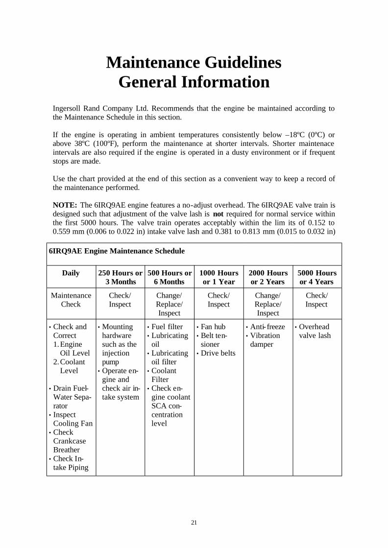
Ingersoll Rand Company Ltd. Recommends that the engine be maintained according to the Maintenance Schedule in this section. If the engine is operating in ambient temperatures consistently below –18ºC (0ºC) or above 38ºC (100ºF), perform the maintenance at shorter intervals. Shorter maintenace intervals are also required if the engine is operated in a dusty environment or if frequent stops are made. Use the chart provided at the end of this section as a convenient way to keep a record of the maintenance performed. NOTE: The 6IRQ9AE engine features a no-adjust overhead. The 6IRQ9AE valve train is designed such that adjustment of the valve lash is not required for normal service within the first 5000 hours. The valve train operates acceptably within the lim its of 0.152 to 0.559 mm (0.006 to 0.022 in) intake valve lash and 0.381 to 0.813 mm (0.015 to 0.032 in)
6IRQ9AE Engine Maintenance Schedule
Daily 250 Hours or 3 Months
500 Hours or 6 Months
1000 Hours or 1 Year
2000 Hours or 2 Years
5000 Hours or 4 Years
Maintenance Check
Check/ Inspect
Change/Replace/Inspect
Check/ Inspect
Change/Replace/Inspect
Check/ Inspect
• Check and Correct 1.Engine
Oil Level 2.Coolant
Level • Drain Fuel-
Water Sepa-rator
• Inspect Cooling Fan
• Check Crankcase Breather
• Check In-take Piping
• Mounting hardware such as the injection pump
• Operate en-gine and check air in-take system
• Fuel filter • Lubricating
oil • Lubricating
oil filter • Coolant
Filter • Check en-
gine coolant SCA con-centration level
• Fan hub • Belt ten-
sioner • Drive belts
• Anti- freeze • Vibration
damper
• Overhead valve lash

22
THIS PAGE IS LEFT INTENTIONALLY BLANK

23
DAILY MAINTENANCE PROCEDURES
GENERAL INFORMATION
Preventive maintenance begins with day-to-day awareness of the condition of the engine and its systems. Before starting the engine, check the oil and coolant levels. Look for the following: • Leaks • Loose or damaged parts, especially in fuel or exhaust systems • Worn or damaged belts • Any change in engine appearance • Odour of fuel.
24
THIS PAGE IS LEFT INTENTIONALLY BLANK

25
Fuel-Water Separator Drain Warning: Drain the fuel-water sepa-rator into a container, and dispose of the contents in accordance with local environmental regulations. Avoid con-tact with skin. NOTE: The water and sediment can contain petroleum products. Please con-sult the local environmental agency for recommended disposal guidelines. Ingersoll Rand Ltd. Requires the a fuel-water separator be installed in the fuel supply system. Drain the water and sedi-ment from the separator daily. Shut off the engine. Open the drain valve by hand. Open the drain valve until the fluid drains out of the drain tube. Drain the filter sump until clear fuel is visible. Lubricating Oil Level Maintenance Check The compressor must be level when checking the oil level to make sure the measurement is correct. Shut off the engine for an accurate read-ing. Do not operate the engine with the oil level below the ‘L’ (low) mark or above the ‘H’ (High) mark. Wait at least 10 minutes after shutting off the engine to check the oil. This allows time for the oil to drain into the pan.

26
Coolant Level Maintenance Check Do not remove the pressure cap from a hot engine. Wait until the coolant tem-perature is below 50ºC (122ºF) before removing the pressure cap. Heated coolant spray or steam can cause per-sonal injury. Never use a sealing additive to stop leaks in the cooling system. This can result in cooling system plugging and inadequate coolant flow, causing the engine to overheat and the cooling sys-tem to fail. The coolant level must be checked daily. Do not add cold coolant to a hot en-gine. Engine castings can be damaged. Allow the engine to cool to below 50ºC (122ºF) before adding coolant. If additional coolant is added to the cool-ing system, a 50-percent mixture of wa-ter and antifreeze must be premixed be-fore being added to the system. Since the ability of antifreeze to remove the heat from the system is not as good as water, pouring antifreeze into the engine first could contribute to an overheated cond i-tion before the liquids are completely mixed. Fill the cooling system with coolant to the bottom of the fill neck on the radia-tor.

27
Cooling Fan Inspect Do not rotate the engine by pulling or prying on the fan. The fan blade(s) can be damaged and cause serious per-sonal injury or property damage. Use the engine barring gear to rotate the crankshaft. Inspect the cooling fan daily. Check for cracks, loose rivets, and bent or loose blades. Check the fan to make sure that it is securely mounted. Tighten the cap-screws, if necessary. Do not straighten a bent fan blade or continue to use a damaged fan. A bent or damaged fan blade can fail during operation and cause serious personal injury or damage to property. Replace any original equipment fan that is damaged with a fan of the identical part number. Ingersoll Rand Ltd. must approve any other fan changes.

28
Air Intake Piping Maintenance Check Inspect the intake piping daily for wear points, damage to piping, loose clamps, and punctures that can damage the en-gine. Replace damaged pipes, and tighten loose clamps, as necessary, to prevent the air system from leaking. Torque Value: 8Nm Check for corrosion under the clamps and hoses of the intake system piping. Corrosion can allow corrosive product and dirt to enter the intake system. Re-move clamps and hoses, and clean as re-quired. Crankcase Breather Tube Maintenance Check Check the crank case breather tube daily during cold weather operation for ice build-up, that can obstruct the tube. If an ice build-up is present, remove the breather tube, if necessary, and clear the obstruction. The 6IRQ9AE engine is equipped with a block-mounted breather tube.

29
MAINTENACE PROCEDURES AT 250 HOURS OR 3 MONTHS
GENERAL INFORMATION All checks or inspections listed under daily or periodic maintenance intervals must also be performed at this time, in addition to those listed under this maintenance interval. Ingersoll Rand can not be responsible for problems caused by non-genuine filters that do not meet Ingersoll Rand’s performance or durability requirements.
Charge-Air Piping Maintenance Check Inspect the charge-air piping and hoses for holes, cracks and loose connections. Tighten the hose cracks if necessary. Torque Value: 8Nm (71 in- lb) Charge-Air Cooler Maintenance Check Inspect the charge-air cooler for dirt and debris blocking the fins. Check for cracks, holes, and other damage. If dam-age is found. The cooler must be repaired or replaced.

30
Air Intake Restriction Maintenance Check The maximum intake restriction is 635 mm (25 in) of water for turbocharged en-gines. Turbocharged engines must be operated at rated rpm and full load to check maxi-mum intake air restriction. Replace the air cleaner element when the restriction reaches the maximum allowable limit. Never operate the engine without an air cleaner. Intake air must be filtered to prevent dirt and debris from enter-ing the engine and causing premature wear. NOTE: Follow the instructions carefully when cleaning or replacing the air cleaner element. Check the air cleaner service indicator, if equipped. Change the filter element when the red indicator flag (2) is at the raised position in the window (1). After the air cleaner has been serviced, push the button (3) to reset the service indicator. FUEL PUMP Maintenance Check Inspect the fuel injection pump mounting nuts, including the tail support bracket and the top support bracket, for loose and damaged hardware.

31
MAINTENACE PROCEDURES AT 500 HOURS OR 6 MONTHS
GENERAL INFORMATION All checks or inspections listed under daily or periodic maintenance intervals must also be performed at this time, in addition to those listed under this maintenance interval. Ingersoll Rand can not be responsible for problems caused by non-genuine filters that do not meet Ingersoll Rand’s performance or durability requirements.
OIL DRAIN INTERVALS Warning Used engine oil can be carcinogenic and cause reproductive toxicity. Avoid inhalation of vapours, ingestion, and prolonged contact with used engine oil. To avoid personal injury, avoid direct contact of hot oil with your skin. Change the lubricating oil and filter(s) at the specified oil change interval. Operate the engine until the engine cool-ant temperature reaches 60º (140ºF). Shut off the engine. NOTE: use a container that can hold at least 24 litres of lubricating oil. Remove the oil drain plug from the bot-tom of the lubricating oil sump.
32
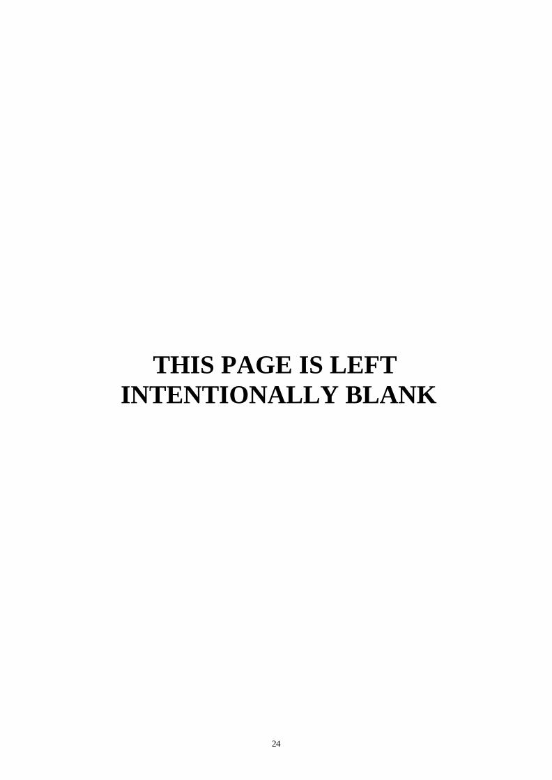
Remove the Oil Filter Clean the area around the lubricating oil filter head. Remove the filter. Clean the gasket surface of the filter head. NOTE: The O-ring can stick on the filter head. Make sure that it is removed before installing the new filter. Make sure that the correct oil filter is used: Ingersoll Rand CPN: 22177737 NOTE: Fill the filter with clean lubricat-ing oil before installation. Apply a light film of lubricating oil to the gasket sealing surface before install-ing the filter. Mechanical over tightening can distort the threads or damage the filter ele-ment seal. Install the filter by hand as specified.
33
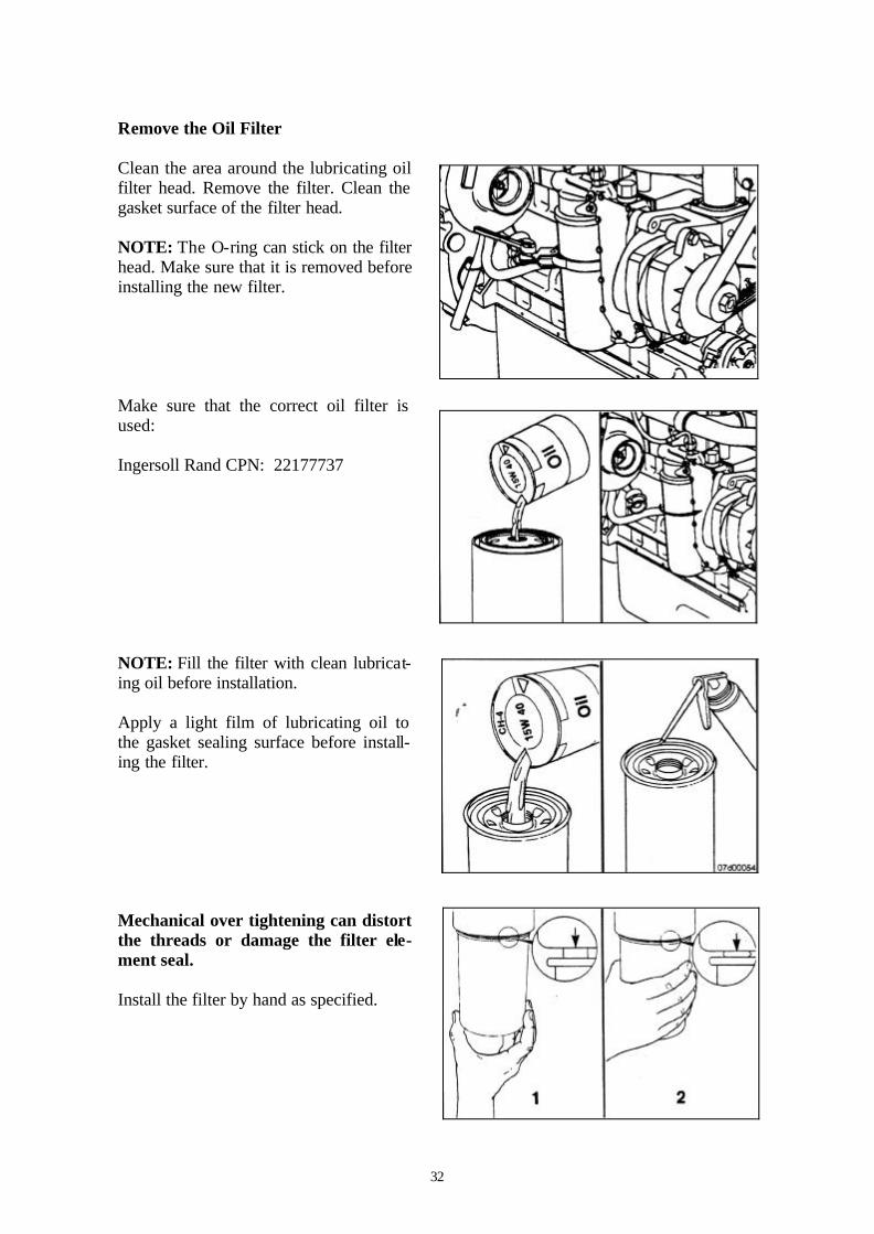
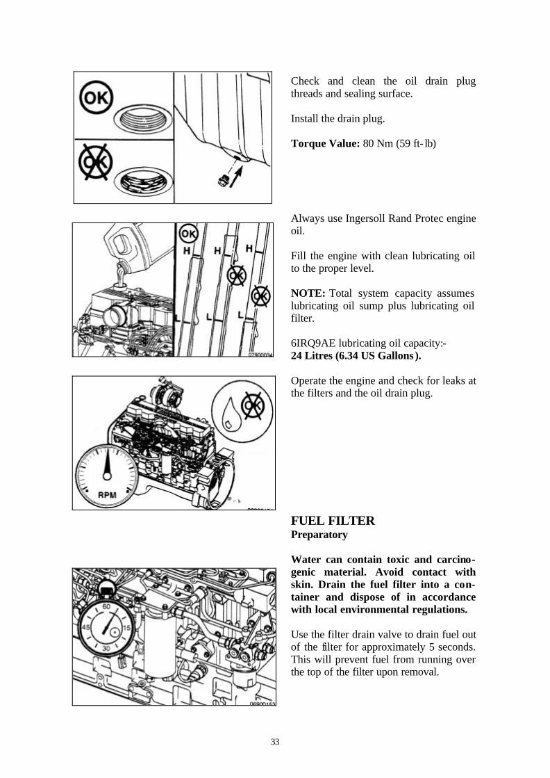
Check and clean the oil drain plug threads and sealing surface. Install the drain plug. Torque Value: 80 Nm (59 ft- lb) Always use Ingersoll Rand Protec engine oil. Fill the engine with clean lubricating oil to the proper level. NOTE: Total system capacity assumes lubricating oil sump plus lubricating oil filter. 6IRQ9AE lubricating oil capacity:- 24 Litres (6.34 US Gallons ). Operate the engine and check for leaks at the filters and the oil drain plug. FUEL FILTER Preparatory Water can contain toxic and carcino-genic material. Avoid contact with skin. Drain the fuel filter into a con-tainer and dispose of in accordance with local environmental regulations. Use the filter drain valve to drain fuel out of the filter for approximately 5 seconds. This will prevent fuel from running over the top of the filter upon removal.

34
Clean all debris from around the fuel fil-ter head. Remove Disconnect the water- in-fuel sensor from the wiring harness. Remove the fuel filter Drain the fuel filter. Remove the water-in-fuel sensor from the fuel filter.

35
Inspect for Reuse Inspect the water- in-fuel sensor for cracks and damage. Install Install the water- in-fuel sensor into the new fuel filter. Ingersoll Rand CPN 22177711. If necessary. The 6IR9QAE engine has a self-priming, low pressure system that purges the air from the fuel system. Do not pre-fill the fuel filter. Pre-filling the fuel filter can cause fuel pump damage. Lubricate the o-ring with clean lubricat-ing oil. Mechanical over tightening can distort the threads as well as damage the filter element seal or filter canister. Install the filter as specified.

36
Connect the water- in-fuel sensor to the wiring harness. Connect the wiring harness to the heater (if equipped). Turn the key to the RUN position, but do not attempt to start the engine for 30 sec-onds. The electric fuel transfer pump will run and purge air from the system for about 30 seconds. After 30 seconds, at-tempt to start the engine. If the engine does not start, turn the key to the OFF position for approximately 30 seconds to allow the electronic module to power down. Turn the key to the ON position allowing the electric fuel transfer pump to cycle again. After 30 seconds attempt to start the engine again. If the engine cranks for 30 seconds with-out starting, vent the fuel supply lines. To vent the fuel supply lines, loosen the banjo fitting on the fuel pump inlet. Run the electric fuel transfer pump until the air has been bled from the system. Operate the engine, and check for leaks.

37
Cooling System Maintenance Check Over concentration of antifreeze or use of high-silicate antifreeze can cause engine damage. Check the antifreeze concentration. Use a mixture of 50 percent water and 50 per-cent ethylene glycol or propylene-glycol-based antifreeze to protect the engine to –32ºC (-26ºF) year-around. NOTE: Antifreeze is essential in every climate. Antifreeze broadens the operating tem-perature range by lowering the coolant freezing point and by raising it’s boiling point. The corrosion inhibitors also protect the cooling system components from corro-sion and prolong components life. Inadequate concentration of the cool-ant additive can result in major corro-sive damage to the cooling system components. Over concentration can cause formation of a ‘gel’ that can cause restriction, plugging of coolant passages, or overheating. NOTE: If the engine coolant is changed, the coolant filters must also be changed. Ingersoll Rand CPN: 36868156 Coolant Filter Preparatory Do not remove the pressure cap from a hot engine. Wait until the coolant tem-perature is below 50ºC (122ºF) before removing the pressure cap. Heated coolant spray or steam can cause per-sonal injury.

38
Remove Do not remove the pressure cap from a hot engine. Wait until the coolant tem-perature is below 50ºC (122ºF) before removing the pressure cap. Heated coolant spray or steam can cause per-sonal injury. Turn the shutoff valve to the OFF posi-tion by rotating the knob from vertical to horizontal in the direction shown in the illustration. Remove and discard the coolant filter. Clean Clean the gasket surface.
39
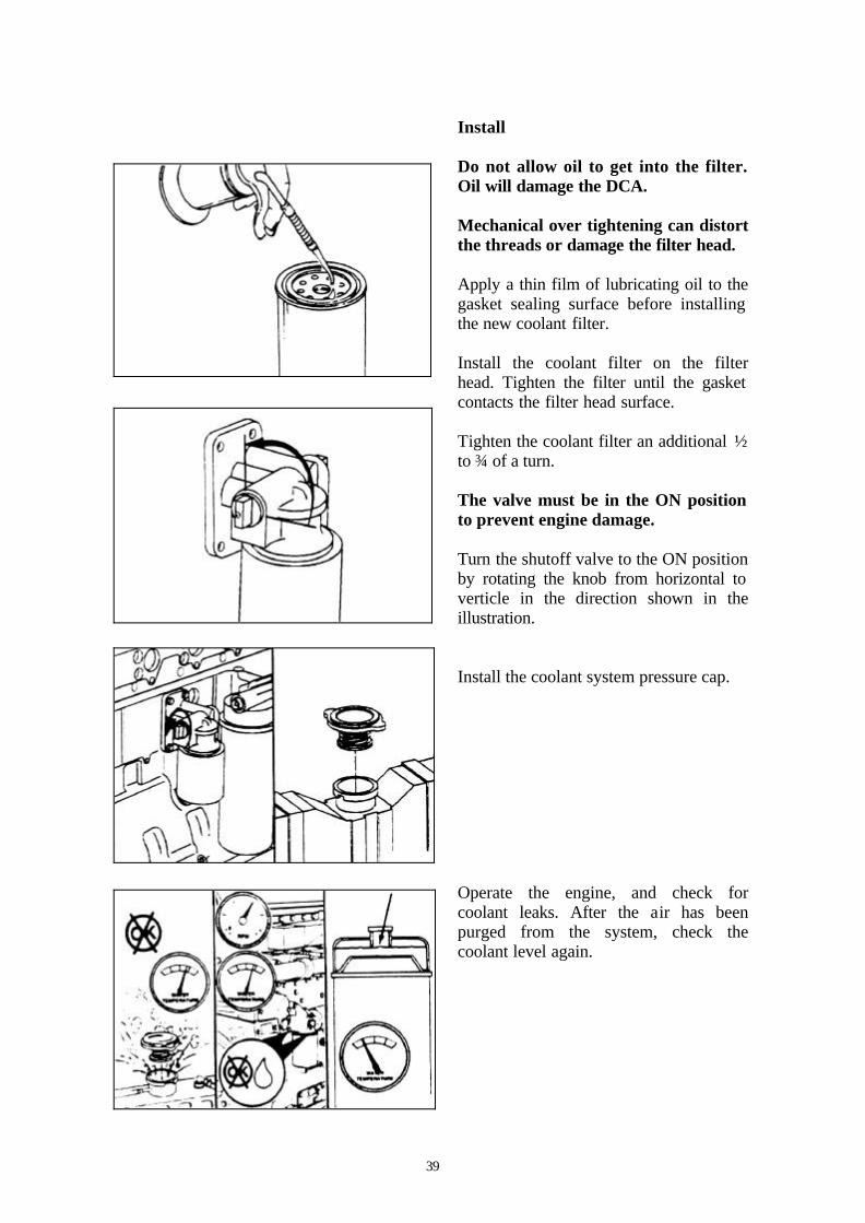
Install Do not allow oil to get into the filter. Oil will damage the DCA. Mechanical over tightening can distort the threads or damage the filter head. Apply a thin film of lubricating oil to the gasket sealing surface before installing the new coolant filter. Install the coolant filter on the filter head. Tighten the filter until the gasket contacts the filter head surface. Tighten the coolant filter an additional ½ to ¾ of a turn. The valve must be in the ON position to prevent engine damage. Turn the shutoff valve to the ON position by rotating the knob from horizontal to verticle in the direction shown in the illustration. Install the coolant system pressure cap. Operate the engine, and check for coolant leaks. After the air has been purged from the system, check the coolant level again.

40
THIS PAGE IS LEFT INTENTIONALLY BLANK

41
MAINTENACE PROCEDURES AT 1000 HOURS OR 1 YEAR
GENERAL INFORMATION All checks or inspections listed under daily or periodic maintenance intervals must also be performed at this time, in addition to those listed under this maintenance interval. Ingersoll Rand can not be responsible for problems caused by non-genuine filters that do not meet Ingersoll Rand’s performance or durability requirements.
Drive Belts Maintenance Check Inspect the belts daily. Check the belts for intersecting cracks. Transverse (across the belt width) are acceptable. Longitudinal (direction of the belt length) cracks that intersect the traverse cracks are not acceptable. Replace the belt if it is frayed or has pieces of mate-rial missing. Refer to section X for belt adjustment and replacement procedures. Belt damage can be caused by • Incorrect tension • Incorrect size or length • Pulley misalignment • Incorrect installation • Severe operating environment • Oil and grease on the belts Fan Hub, Belt Driven Maintenance Check Remove the drive belt
42
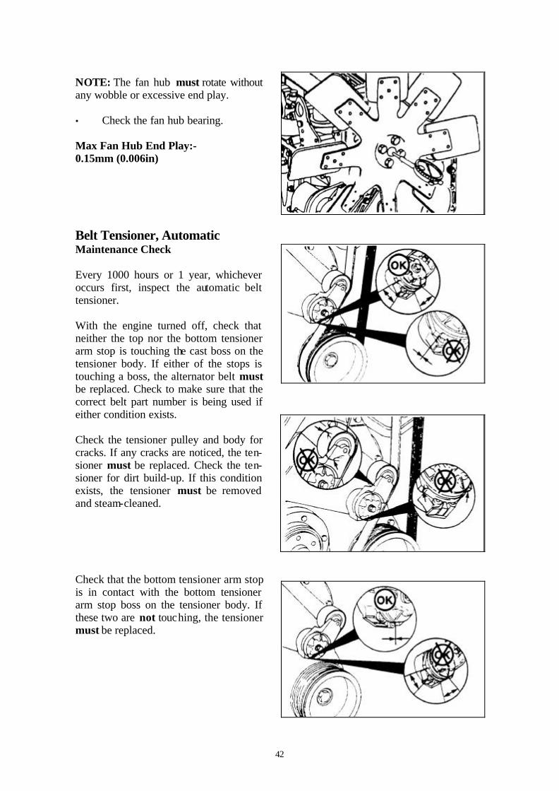
NOTE: The fan hub must rotate without any wobble or excessive end play. • Check the fan hub bearing. Max Fan Hub End Play:- 0.15mm (0.006in) Belt Tensioner, Automatic Maintenance Check Every 1000 hours or 1 year, whichever occurs first, inspect the automatic belt tensioner. With the engine turned off, check that neither the top nor the bottom tensioner arm stop is touching the cast boss on the tensioner body. If either of the stops is touching a boss, the alternator belt must be replaced. Check to make sure that the correct belt part number is being used if either condition exists. Check the tensioner pulley and body for cracks. If any cracks are noticed, the ten-sioner must be replaced. Check the ten-sioner for dirt build-up. If this condition exists, the tensioner must be removed and steam-cleaned. Check that the bottom tensioner arm stop is in contact with the bottom tensioner arm stop boss on the tensioner body. If these two are not touching, the tensioner must be replaced.
43
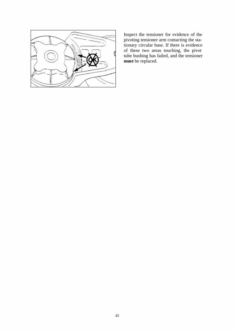
Inspect the tensioner for evidence of the pivoting tensioner arm contacting the sta-tionary circular base. If there is evidence of these two areas touching, the pivot tube bushing has failed, and the tensioner must be replaced.

44
THIS PAGE IS LEFT INTENTIONALLY BLANK

45
MAINTENACE PROCEDURES AT 2000 HOURS OR 2 YEARS
GENERAL INFORMATION All checks or inspections listed under daily or periodic maintenance intervals must also be performed at this time, in addition to those listed under this maintenance interval. Ingersoll Rand can not be responsible for problems caused by non-genuine filters that do not meet Ingersoll Rand’s performance or durability requirements.
Cooling System Drain Do not remove the pressure cap from a hot engine. Wait until the coolant tem-perature is below 50ºC (122ºF) before removing the pressure cap. Heated coolant spray or steam can cause personal injury. Avoid prolonged or reated skincontact with used antifreeze. Such prolonged, repea ted contac t can cause skindisorders or other bodily injury. Wash skin thoroughly after conteact. Protect the environment: Handling and disposing of used antifreeze is subject to federal, state, and local regulations. Use authorised waste disposal facilities, including civil amenity sites and garages providing authorised facilities for the receipt of used antifreeze. If in doubt, contact local authorities of the Enviromental Protection Agency (EPA) for guidance as to proper halding of antifreeze. Coolant is toxic. If not reused, dispose of in accordance wi th local environmental regulations.

46
Drain the cooling system by opening the drain vale on the radiator and removing the plug in the bottom of the water inlet hose. A drain pan with a capacity of 19 litres (5 gal) will be adequate. Check for damaged hoses and loose or damaged hose clamps. Replace as re-quired. Check the radiator for leaks, damage, and build-up of dirt. Clean and replace as required. Flush The system must be filled properly to prevent air locks. During filling, air must be purged from the engine cool-ant passages. Be sure to open the pe t-lock on the aftercooler. Wait 2 to 3 minutes to allow air to be vented; then add mixture to bring the level to the top. Note: Adequate venting is provide for a fill rate of 19 litres (5 gal) per minute. Do not install the radiator cap. The en-gine is to be operated without the cap for this process. Fill the system with a mixture of sodium carbonate and water (or a commercially available equivalent). NOTE: Use 0.5 Kg (1lb) of sodium car-bonate for every 23 litres (6 gal) of wa-ter.

47
Coolant is toxic. If not reused, dispose of in accordance with local environ-mental regulations. Operate the engine for 5 minutes with the coolant temperature above 80ºC (176ºF). Shut the engine off, and drain the cooling system. Fill the cooling system with high-quality water. Note: Be sure to vent the engine and af-tercooler for complete filling. Note: Do not install the radiator cap or the new coolant filter. Operate the engine for 5 minutes with the coolant temperature above 80ºC (176ºF). Shut the engine off, and drain the cooling system. NOTE: If the water being drained is still dirty, the system must be flushed again until the water is clean. Fill The system must be filled properly to prevent air locks. During filling, the air must be vented from the engine coolant passages. Be sure to open the pet lock on the aftercooler. Wait 2 to 3 minutes to allow the air to be vented; then add the mixture to bring the level to the top. The system is designed to use a specific quantity of coolant. If the coolant level is low, the engine will run hot.

48
If frequent additional coolant is neces-sary, the engine or system has a leak. Find and repair the leak. The system is designed for a fill rate of 19 litres (5 gal) per minute. Never use water alone for engine cool-ant. This can result in damage from corrosion. Use a mixture of 50 percent water and 50 percent ethylene glycol or propylene-glycol-based antifreeze to fill the cooling system. Do not remove the pressure cap from a hot engine. Wait until the coolant tem-perature is below 50ºC (122ºF) before removing the pressure cap. Heated coolant spray or steam can cause personal injury. Install the pressure cap. Operate the engine until the coolant reaches a temperature of 80ºC (176ºF), and check for coolant leaks. Check the coolant level again to make sure that the system is full of coolant or that the coolant level has risen to the hot level in the recovery bottle on the compressor. Vibration Damper, Rubber Inspect Check the index lines (A) in the vibration damper hub (B) and the inertia member (C). If the lines are more than 1.59mm (0.06in) out of alignment, replace the vibration damper.

49
Inspect the rubber member for deteriora-tion. If pieces of the rubber are missing, or if the elastic member is more than 3.18 mm (0.13 in) below the metal sur-face, replace the damper. NOTE: Look for forward movement on the damper ring on the hub. Replace the vibration damper if any movement is de-tected. Vibration Damper Inspect The silicone fluid in the vibration damper will become solid after ex-tended service and will make the damper inoperative. An inoperative damper can cause major engine or drivetrain failures. Check the vibration damper for evidence of fluid loss, dents, and wobble. Inspect the vibration damper thickness for any deformation or raising of the damper cover plate.

50
THIS PAGE IS LEFT INTENTIONALLY BLANK

51
MAINTENACE PROCEDURES AT 5000 HOURS OR 4 YEARS
GENERAL INFORMATION All checks or inspections listed under daily or periodic maintenance intervals must also be performed at this time, in addition to those listed under this maintenance interval. Ingersoll Rand can not be responsible for problems caused by non-genuine filters that do not meet Ingersoll Rand’s performance or durability requirements.
Overhead Set General Information A valve lash check must be performed at 5000 hours and at 1500 hours thereafter. Measure Engine coolant temperature must be less than 60ºC (140ºF). Remove then plastic fuel pump drive cover located on the front of the engine. Use the engine barring tool, to rotate the crankshaft to align top dead centre (TDC) marks on the gear cover and fuel pump gear. Remove the rocker lever cover and gas-ket.

52
With the engine in this position, the lash can be reset on the following rocker: 1I, 1E, 2I, 3E, 4I and 5E.
Nominal Valve Lash
Intake 0.305mm nominal 0.012in Exhaust 0.559mm nominal 0.022in Reset the lash to the nominal specifica-tion above. NOTE: Valve lash measurements are sometimes performed as part of a trou-bleshooting procedure. If the lash meas-urement does not coincide with a sched-uled lash reset (5000 hours or 1500 hours thereafter), and the measurement falls within the following range the lash does not need to be reset. Lash measurements in this range will not affect engine per-formance, noise, emissions, or durability.
Valve Lash Acceptable Range
Intake 0.152mm MIN 0.012in 0.559mm MAX 0.022in Exhaust 0.381mm MIN 0.015in 0.813mm MAX 0.032in Reset the valve lash by inserting the proper feeler gauge between the cross-head and the rocker lever ball insert and socket. If the lash measurement is out of specification, loosen the locknut, and ad-just the lash to nominal specifications. Tighten the locknut to the rocker lever, and measure again.

53
Use a barring tool to rotate the crankshaft 360 degrees (the mark on the fuel pump gear rotates 180 degrees), and measure the lash for rocker arms 2E, 3I, 4E, 5I, 6I and 6E. Reset to nominal specifications. Install the gasket and rocker lever cover. Torque Value: 12 Nm (106 in- lb) Install the fuel pump drive cover.

54
THIS PAGE IS LEFT INTENTIONALLY BLANK

55
TROUBLESHOOTING PROCEDURES AND TECHNIQUES
GENERAL INFORMATION This guide describes some typical engine operating problem, their causes and some ac-ceptable corrections to those problems. Unless noted otherwise, the problems listed are those which an operator can diagnose and repair. Performing troubleshooting procedures NOT outlined in this section can result in equipment damage or personal injury or death. Troubleshooting must be performed by trained, experienced technicians. Consult an Ingersoll Rand Authorised Service Location for diagnosis and repair beyond that which is outlined and for symptoms not listed in this section. Follow the suggestions below for troubleshooting:
• Study the complaint thoroughly before acting
• Refer to the engine system diagrams
• Do the easiest and most logical things first
• Find and correct the cause of the complaint Use the following chars to aid in diagnosing specific engine symptoms. Read each row of blocks from top to bottom. Follow the arrows through the chart to identify corrective ac-tion.
56
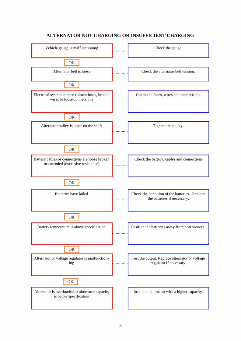
ALTERNATOR NOT CHARGING OR INSUFFICIENT CHARGING
Vehicle gauge is malfunctioning
Check the gauge.
Alternator belt is loose
Check the alternator belt tension.
OK
Electrical system is open (blown fuses, broken wires or loose connections
Check the fuses, wires and connections.
OK
Alternator pulley is loose on the shaft
Alternator is overloaded or alternator capacity is below specification
Alternator or voltage regulator is malfunction-ing
Battery temperature is above specification
Battery cables or connections are loose broken or corroded (excessive resistance)
Batteries have failed
OK
OK
OK
OK
Tighten the pulley.
Check the battery, cables and connections
Check the condition of the batteries. Replace the batteries if necessary.
Position the batteries away from heat sources.
Test the output. Replace alternator or voltage regulator if necessary.
Install an alternator with a higher capacity.
OK
OK

57
ALTERNATOR OVERCHARGING Cause Correction
Battery cell is damaged (open circuit)
Check condition of the batteries. Replace the batteries if necessary.
Voltage regulator is malfunctioning
Check the voltage regulator. Replace the volt-age regulator if necessary.
OK
58
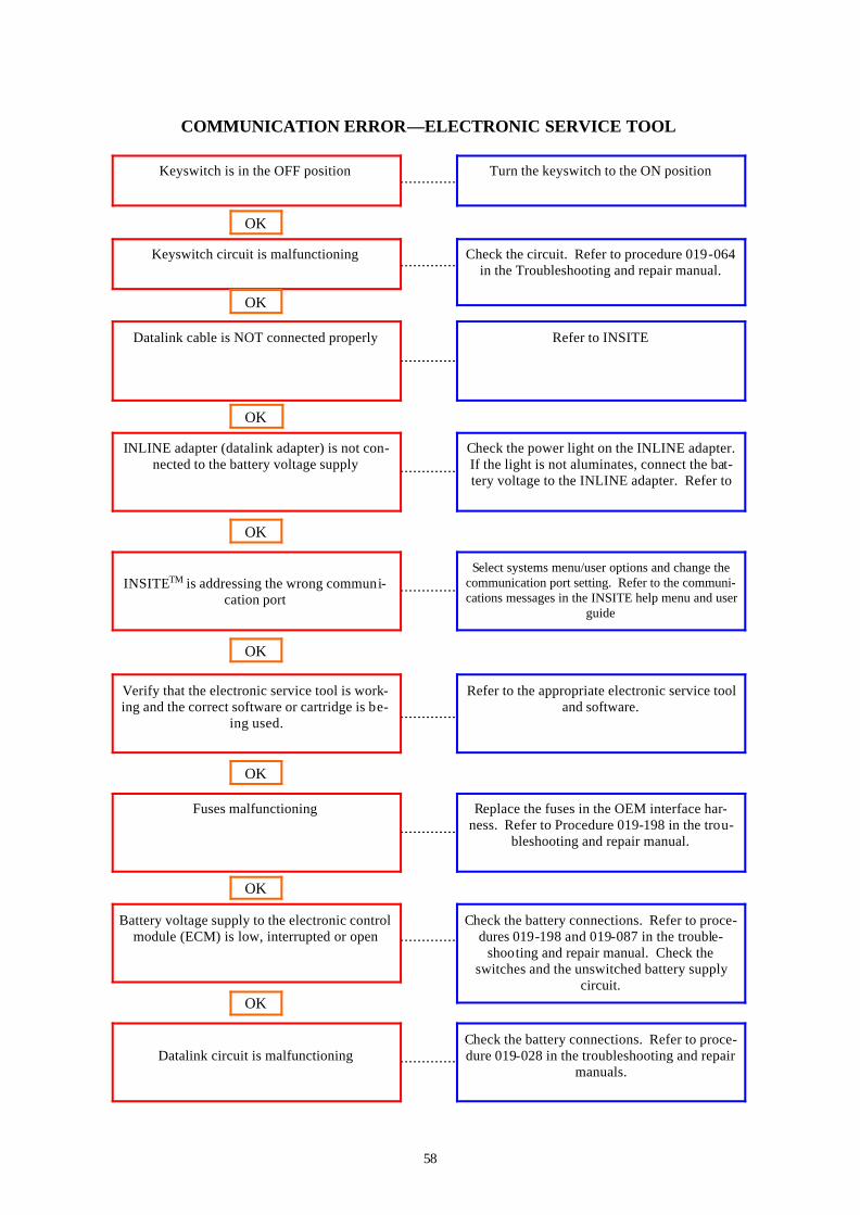
COMMUNICATION ERROR—ELECTRONIC SERVICE TOOL
Keyswitch is in the OFF position
Turn the keyswitch to the ON position
Keyswitch circuit is malfunctioning
Check the circuit. Refer to procedure 019-064 in the Troubleshooting and repair manual.
OK
Datalink cable is NOT connected properly Refer to INSITE
OK
INLINE adapter (datalink adapter) is not con-nected to the battery voltage supply
Datalink circuit is malfunctioning
Battery voltage supply to the electronic control module (ECM) is low, interrupted or open
Fuses malfunctioning
INSITETM is addressing the wrong communi-
cation port
Verify that the electronic service tool is work-ing and the correct software or cartridge is be-
ing used.
OK
OK
OK
OK
Check the power light on the INLINE adapter. If the light is not aluminates, connect the bat-tery voltage to the INLINE adapter. Refer to
Select systems menu/user options and change the communication port setting. Refer to the communi-cations messages in the INSITE help menu and user
guide
Refer to the appropriate electronic service tool and software.
Replace the fuses in the OEM interface har-ness. Refer to Procedure 019-198 in the trou-
bleshooting and repair manual.
Check the battery connections. Refer to proce-dures 019-198 and 019-087 in the trouble-
shooting and repair manual. Check the switches and the unswitched battery supply
circuit.
Check the battery connections. Refer to proce-dure 019-028 in the troubleshooting and repair
manuals.
OK
OK

59
COMMUNICATION ERROR—ELECTRONIC SERVICE TOOL (CONT)
Electronic fault codes active or high counts of inactive fault codes
Refer to section TF in the Troubleshooting and repair manual
Electronic Control Module (ECM) is NOT calibrated
Calibrate the ECM. Refer to the electronic service tool manuals and procedures.
OK
J939 control devices are interfering with the engine controls
Alternately disconnect all other J939 con-trol devices from the datalink circuit until
communications or functionality is re-stored.
OK
Electronic Service Tool COM port has been interrupted or is malfunctioning
Electronic control module (ECM) is mal-functioning
Moisture in the wiring harness connectors
J1939 datalink shield is NOT grounded cor-rectly
OK
OK
OK
OK
Refer to the Electronic Service Tools and Palm Pilot manuals
Dry the connectors.
Repair the electronic ground for the data-link shield.
Replace the ECM.

60
COOLANT LOSS—EXTERNAL
Coolant level is above specification
Check the coolant level.
External coolant leak
Inspect the engine for coolant leaking from hoses, drain cock, water manifold, jumper
tubes, expansion and pipe plugs, fitting, radia-tor core, air compressor and cylinder head gas-
kets, lubricating oil cooler, water pump seal and Compressor mounted components that
have coolant flow. If necessary, pressure test the cooling system
OK
Radiator cap is NOT correct, is malfunctioning
or has low-pressure rating
Engine is overheating
Fill line or vent lines are restricted, obstructed
or NOT routed correctly
Coolant line is restricted or obstructed.
Aftercooler is leaking
Cooling system hose is collapsed, restricted or
leaking
OK
OK
OK
OK
Check the radiator pressure cap.
Check the aftercooler and connections for
leaks.
Inspect the radiator hoses.
Check the coolant fill line for restrictions or
obstructions
Check the vent lines and the fill line for correct routing and for restriction.
Refer to the coolant temperature above normal
symptom flow chart
OK
OK

61
COOLANT LOSS—INTERNAL
Lubricating oil cooler is leaking
Check the lubricating oil cooler for coolant leaks.
Cylinder block is cracked or porous
Remove the oil pan. Pressure-test the cooling system to check for leaks
OK

62
COOLANT TEMPERATURE IS ABOVE NORMAL—SUDDEN OVERHEAT
Coolant level is below specification
Inspect the engine and cooling system for external coolant leak. Repair if necessary.
Electronic fault codes active or high counts of inactive fault codes
Refer to section TF in the troubleshooting and repair manual.
OK
Cold weather radiator cover or winterfront is
closed.
Open the cold weather radiator cover or the winterfront. Maintain a min. of 784 cm2
(120 in2), or approx. 28 x 28 cm ( 11 x 11 in) of opening at all times
OK
Fan drive belt is broken
Water pump is malfunctioning
Thermostat is NOT correct or is
malfunctioning
Cooling system hose is collapsed, restricted or
leaking
Coolant temperature gauge is malfunctioning
Radiator cap is NOT correct, is malfunctioning
or has low pressure rating.
OK
OK
OK
OK
Check the fan drive belt. Replace the belt, if necessary
Test the temperature gauge. Repair or replace the gauge, if necessary.
Check the radiator pressure cap.
Inspect the radiator hoses.
Check the thermostat for the correct part number and correct operation.
Check the water pump. Replace water pump if necessary
OK
OK

63
COOLANT TEMPERATURE IS ABOVE NORMAL—SUDDEN OVERHEAT
Charge-air cooler (CAC) fins, radiator fins or air conditioner condenser fins are damaged or
obstructed with debris
Inspect the CAC, air conditioner condenser and radiator fins. Clean if necessary.
OK
Cooling system component is malfunctioning Perform the cooling system diagnostics test.
Fan drive or fan controls are malfunctioning
Fill line or vent lines are restricted, obstructed, or NOT routed correctly
Radiator shutters are NOT opening completely, or the shutterstat setting is wrong
Torque converter cooler or hydraulic oil cooler is malfunctioning
OK
OK
OK
OK
Check the fan drive and controls.
Inspect the radiator shutters. Repair or replace if necessary. Check the shutterstat settings.
Remove and inspect the cooler cores and ‘O’ rings.
Check vent lines and the fill line for correct routing and for restriction.

64
COOLANT TEMPERATURE IS BELOW NORMAL Cause Correction
Coolant temperature gauge or sensor is ma l-functioning
Test the gauge and the sensor. Repair or replace if necessary.
Electronic fault codes active or high counts or inactive fault codes
Refer to section TF in the troubleshooting and repair manual
OK
Engine operating at a low ambient temperature
Check the winterfront, shutters and canopy air. Use intake air from under the canopy in cold
weather.
OK
Thermostat is NOT correct or is
malfunctioning
Coolant flow through the radiator is NOT
correct
Fan drive or fan controls are malfunctioning
OK
OK
OK
Check the thermostat for the correct part num-
ber and correct operation.
Check for correct coolant flow through the ra-
diator.
Check the fan drive and controls

65
COOLANT IN THE LUBRICATING OIL Cause Correction
Lubricating oil cooler is malfunctioning
Check the oil cooler
Air compressor cylinder head is cracked or po-rous or has a leaking gasket
Inspect the air compressor cylinder head and gasket
OK
Aftercooler is leaking (Aftercooled engines only)
Remove and pressure-test the aftercooler.
OK
Cylinder head core and expansion plugs leak-ing or misassembled.
Cylinder block is cracked or porous.
Cylinder liner is corroded or cracked
OK
OK
OK
Check cylinder head
Inspect the cylinder block
Check the cylinder liners for corrosion or cracks.
66
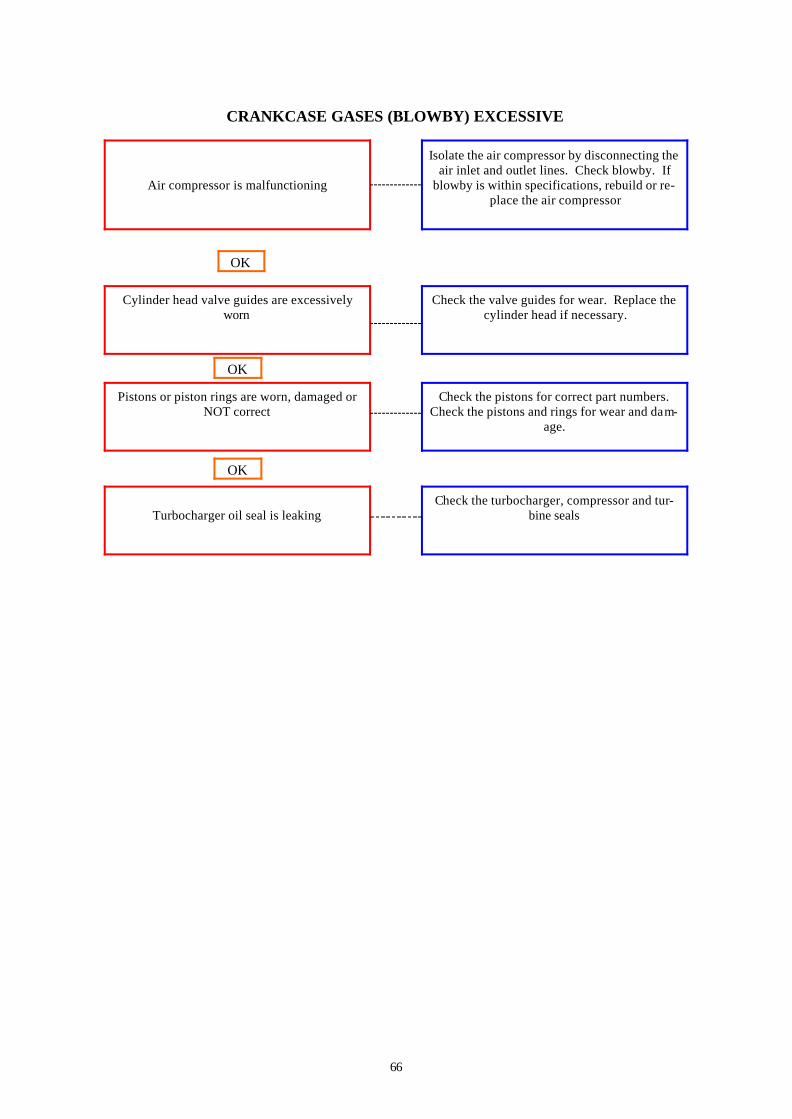
CRANKCASE GASES (BLOWBY) EXCESSIVE
Air compressor is malfunctioning
Isolate the air compressor by disconnecting the air inlet and outlet lines. Check blowby. If
blowby is within specifications, rebuild or re-place the air compressor
Cylinder head valve guides are excessively worn
Check the valve guides for wear. Replace the cylinder head if necessary.
OK
Pistons or piston rings are worn, damaged or NOT correct
Turbocharger oil seal is leaking
OK
OK
Check the pistons for correct part numbers. Check the pistons and rings for wear and dam-
age.
Check the turbocharger, compressor and tur-bine seals
67
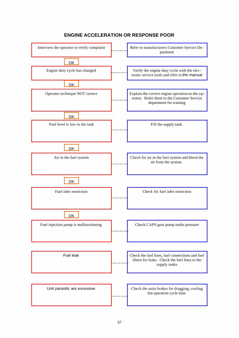
ENGINE ACCELERATION OR RESPONSE POOR
Interview the operator to verify complaint
Refer to manufacturers Customer Service De-partment
Engine duty cycle has changed
Verify the engine duty cycle with the elec-tronic service tools and refer to the manual
OK
Operator technique NOT correct Explain the correct engine operation to the op-erator. Refer them to the Customer Service
department for training
OK
Fuel level is low in the tank
Unit parasitic are excessive
Fuel leak
Fuel injection pump is malfunctioning
Air in the fuel system
Fuel inlet restriction
OK
OK
OK
OK
Fill the supply tank.
Check for air in the fuel system and bleed the air from the system.
Check for fuel inlet restriction
Check CAPS gear pump outlet pressure
Check the fuel lines, fuel connections and fuel filters for leaks. Check the fuel lines to the
supply tanks.
Check the units brakes for dragging, cooling fan operation cycle time

68
ENGINE ACCELERATION OR RESPONSE POOR (CONT)
Charge-air cooler (CAC) is restricted or leak-ing
Inspect the CAC for air restrictions or leaks.
Electronic fault codes active or high counts of
inactive fault codes
Refer to the TF section in the troubleshooting and repair manuals
OK
Programmable parameters or selected features
are NOT correct
Fuel injection pump is malfunctioning
Fuel injection pump is malfunctioning
Fuel injection pump is malfunctioning
Electronic control module (ECM) calibration is
NOT correct
Fuel injection pump is malfunctioning
OK
OK
OK
OK
Check the programmable parameters and the selected features with the electronic service
tools. Set the parameters and features again if necessary. Refer to the electronic service tool.
Compare the calibration stored in the ECM with the engine rating and control parts list. If
necessary, calibrate the ECM.
Perform ICV solenoid click test.
Perform pumping control valve click test
Perform CAPS plunger cut-out test
Check CAPS accumulator pressure
OK
OK

69
ENGINE ACCELERATION OR RESPONSE POOR (CONT)
Intake manifold pressure (boost) sensor or cir-cuit is malfunctioning
Check boost sensor circuit
Engine speed sensor (ESS) or circuit is ma l-functioning
Check ESS for correct adjustment and debris on the sensor. Check the ESS circuit.
OK
Ambient air pressure sensor is malfunctioning
(if equipped)
Check the ambient air temperature sensor.
OK
Fuel supply line restriction between the fuel
pump and the injectors.
Exhaust system restriction is above specifica-
tion
Air intake system restriction is above specifica-
tion
Air intake or exhaust leaks
Fuel connector is leaking
Injector is malfunctioning
OK
OK
OK
OK
Check the fuel supply line from the fuel pump to the cylinder head for sharp bends that can
cause restrictions
Perform the automated cylinder performance test to isolate the cylinder with the leaking fuel connector. Inspect the fuel connector and in-
jector for nicks and damage that can cause fuel leaks
Perform the automated cylinder performance
test
Inspect the air intake and exhaust systems for
air leaks
Check the air intake system for restriction. Clean or replace the air filter and inlet piping if
necessary
Check the exhaust system for restrictions
OK
OK

70
ENGINE ACCELERATION OR RESPONSE POOR(CONT)
J1939 control devices are interfering with the engine controls
Alternatively disconnect all other J1939 control devices from the datalink circuit until commu-nications or functionality is restored. Refer to the OEM service manual to locate and repair
J1939 control devices
Turbocharger is NOT correct Check the turbocharger part number and com-pare it to the control parts list. Replace the tur-
bocharger if necessary.
OK ?
Turbocharger wastegate is malfunctioning
Overhead adjustments are NOT correct
Fuel grade is NOT correct for the application or fuel quality is poor
Fuel inlet temperature to pump is above speci-fication
Turbocharger wheel clearance is out of specifi-cation
Turbocharger is malfunctioning
OK
OK
OK
OK
Check the wastegate for correct operation
Check the radial bearing clearance and axle clearance. Inspect the turbocharger. Repair or
replace if necessary
Monitor the turbocharger boost pressure with the electronic service tools and refer to the
manual. Replace the turbocharger if necessary
Fill the fuel tank, turn off or bypass the fuel heaters and check the fuel cooler.
Operate the engine from a tank of high quality fuel.
Measure and adjust the overhead settings
OK
OK

71
ENGINE ACCELERATION OR RESPONSE IS POOR (CONT)
Injectors are NOT correct
Remove the injectors and compare the parts num-bers to the control parts list. Replace the injectors if
necessary
Fuel injection pump is malfunctioning
Remove and inspect the rate shape snubber valve
OK
Fuel injection pump is malfunctioning Remove and inspect the six fuel pump delivery valves
OK
Fuel injection pump is malfunctioning
Fuel injection pump is malfunctioning
Internal engine damage
OK
OK
OK
Remove and inspect the distributor snubber
Replace the fuel injection pump
Analyse the oil and inspect the filter to locate an area or probable damage.

72
ENGINE IS DIFFICULT TO START OR WILL NOT START (EXHAUST
Fuel level is low in the tank
Fill the supply tank.
Electronic fault codes active or high counts of inactive fault codes
Refer to section TF in troubleshooting and re-pair manual
OK
Battery voltage is low Check the electrolyte level in each cell. Add distilled water if necessary. Check the eye on the maintenance free batteries. Replace batter-
ies if necessary
OK
Air intake restriction is above specification
Fuel injection pump is malfunctioning
Exhaust system restriction is above specifica-
tion
Fuel inlet restriction
Starting aid is necessary for cold weather or starting Aid is malfunctioning
Fuel filter is plugged
OK
OK
OK
OK
Check air intake system for restriction. Clean or replace the air filter and inlet piping as nec-
essary
Check for the correct operation of the starting aid.
Measure the fuel pressure before and after the fuel filter.
Check for fuel inlet restriction
Check the exhaust systems for restrictions
Check for seized distributor rotor.
OK
OK
73
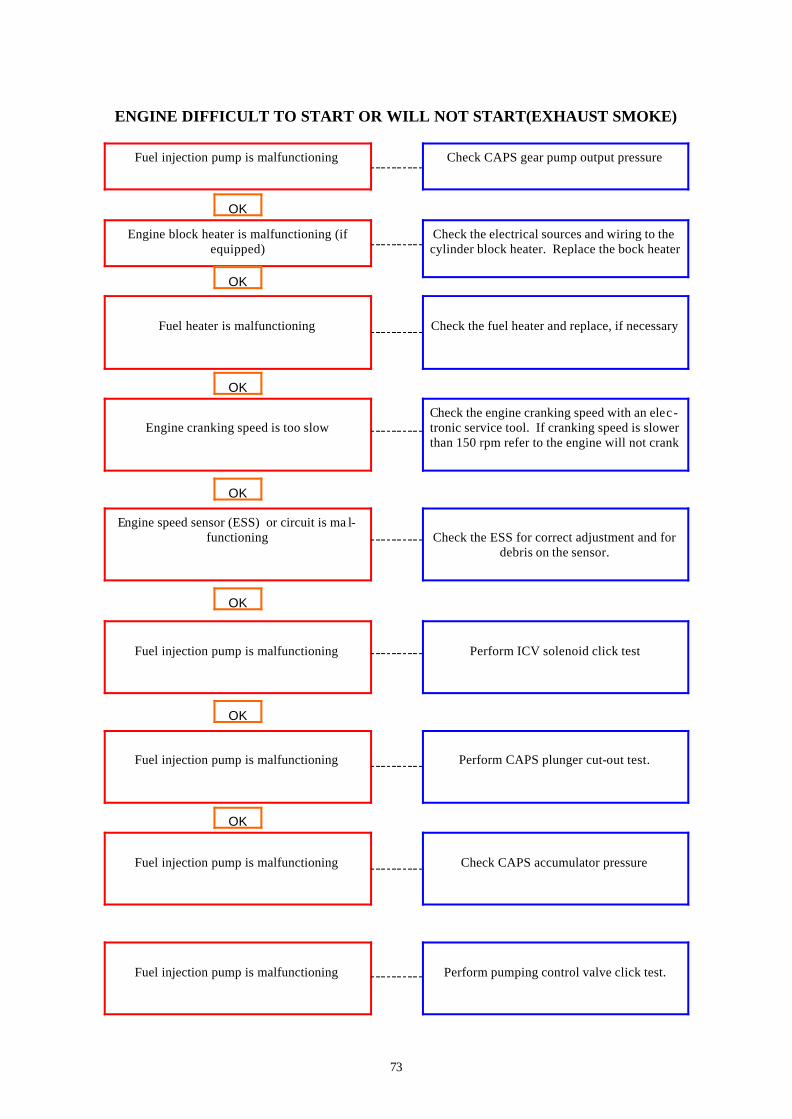
ENGINE DIFFICULT TO START OR WILL NOT START(EXHAUST SMOKE)
Fuel injection pump is malfunctioning
Check CAPS gear pump output pressure
Engine block heater is malfunctioning (if equipped)
Check the electrical sources and wiring to the cylinder block heater. Replace the bock heater
OK
Fuel heater is malfunctioning
Check the fuel heater and replace, if necessary
OK
Engine cranking speed is too slow
Fuel injection pump is malfunctioning
Fuel injection pump is malfunctioning
Fuel injection pump is malfunctioning
Engine speed sensor (ESS) or circuit is ma l-functioning
Fuel injection pump is malfunctioning
OK
OK
OK
OK
Check the engine cranking speed with an elec-tronic service tool. If cranking speed is slower than 150 rpm refer to the engine will not crank
Check the ESS for correct adjustment and for
debris on the sensor.
Perform ICV solenoid click test
Perform CAPS plunger cut-out test.
Check CAPS accumulator pressure
Perform pumping control valve click test.
OK

74
ENGINE DIFFICULT TO START OR WILL NOT START (EXHUAST SMOKE)
Injector shim thickness is NOT correct
Remove the injectors and verify the injector shim thickness.
Fuel connector is leaking
Perform the automated cylinder performance test to isolate the cylinder with the leaking fuel connector. Inspect the fuel connector and in-
jector for nicks and damage that can cause fuel leaks
OK
OK
Fuel supply line is restricted between the fuel pump and the injectors
Overhead adjustments are NOT correct.
Fuel lift pump is malfunctioning
Fuel grade NOT correct for the application or fuel quality is poor
Air in the fuel system
Fuel inlet temperature to pump is above speci-fication
OK
OK
OK
Check the fuel supply line from the fuel pump to the cylinder head for sharp bends that can
cause restrictions
Check for air in the fuel system. Bleed air from the system
Fill the fuel tank, turn off or bypass the fuel heaters and check the fuel cooler.
Operate the engine from a tank of high quality fuel. Refer to the operation and maintenance
manual
Check the fuel lift pump for correct operation. Check the pump output pressure. Replace the
fuel lift pump if necessary.
Measure and adjust the overhead settings.
OK
OK

75
ENGINE DIFFICULT TO START OR WILL NOT START (EXHAUST SMOKE)
Keyswitch circuit is malfunctioning
Check the keyswitch circuit.
Fuel injection pump is malfunctioning
Check the pump to engine timing
OK
Fuel injection pump is malfunctioning Replace the fuel injection pump
OK
Camshaft gear tone wheel loose
Internal engine damage
OK
OK
Check the camshaft tone wheel for tightness
Analyse the oil and inspect the filters to locate an area of probable damage.

76
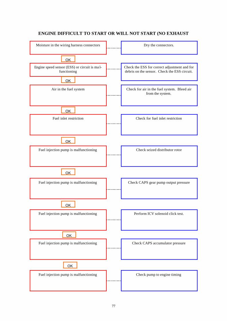
ENGINE DIFFICULT TO START OR WILL NOT START (NO EXHAUST
Fuel level is low in the tank
Fill the supply tank
Electronic fault codes active or high counts of inactive fault
Refer to section TF in the troubleshooting and repair manual
OK
Battery voltage is low Check the batteries and the unswitched batter-ies supply circuit.
OK
Fuse(s) malfunctioning
OEM engine protection system is active or is malfunctioning
Electronic control module (ECM) is NOT cali-brated or has incorrect calibration
Battery voltage supply to the electronic control module (ECM) is low, interrupted or open
Fuel filter is plugged
OK
OK
OK
OK
Replace the fuses in the OEM interface har-ness.
Check the battery connections. Check the fuses and the unswitched battery supply circuit
Measure the fuel pressure before and after the fuel filter
Compare the calibration stored in the ECM with the engine rating and the control parts list.
If necessary calibrate the ECM. Refer to the appropriate electronic service tool manual
Isolate the OEM engine protection system. Follow the OEM service manual to check for
malfunction.
OK
77
ENGINE DIFFICULT TO START OR WILL NOT START (NO EXHAUST
Moisture in the wiring harness connectors
Dry the connectors.
Engine speed sensor (ESS) or circuit is ma l-functioning
Check the ESS for correct adjustment and for debris on the sensor. Check the ESS circuit.
OK
Air in the fuel system Check for air in the fuel system. Bleed air from the system.
OK
Fuel inlet restriction
Fuel injection pump is malfunctioning
Fuel injection pump is malfunctioning
Fuel injection pump is malfunctioning
Fuel injection pump is malfunctioning
Fuel injection pump is malfunctioning
OK
OK
OK
OK
Check for fuel inlet restriction
Check seized distributor rotor
Check CAPS gear pump output pressure
Perform ICV solenoid click test.
Check CAPS accumulator pressure
Check pump to engine timing
OK
OK

78
ENGINE DIFFICULT TO START OR WILL NOT START (NO EXHAUST
Fuel injection pump is malfunctioning
Remove and inspect the rate shape snubber valve
Fuel injection pump is malfunctioning
Replace the fuel injection pump
OK
Camshaft gear speed indicator ring loose Check camshaft gear speed indicator ring for tightness
OK
Electronic control module (ECM) is locked up
Electronic control module (ECM) is malfunc-tioning
Internal engine damage
OK
OK
OK
Disconnect battery cables for 30 seconds. Connect battery cables and start the engine
Replace the ECM
Analyse the oil and inspect the filters to locate an area of probable damage.

79
ENGINE NOISE EXCESSIVE
Fan drive belt is loose
Check the belt tension and tighten if necessary
Fan is loose, damaged or NOT Balanced
Check the fan.
OK
Air intake or exhaust leaks Inspect the air intake and exhaust systems for air leaks
OK
Air intake or exhaust piping is contacting the chassis
Coolant temperature is above specification
Vibration damper is damaged
Lubricating oil pressure is below specification
Lubricating oil level is above or below specifi-cation
Lubricating oil is thin or diluted
OK
OK
OK
OK
Inspect the air piping, chassis for contact points
Check oil level. Add or drain oil if necessary
If oil pressure is low, refer to the lubricating oil pressure low flow chart
Check oil pressure
Inspect vibration damper
Refer to coolant temperature is above normal flow chart
OK
OK

80
ENGINE NOISE EXCESSIVE (CONT)
Engine mounts are worn, damaged or not cor-rect
Check the engine mounts
Overhead adjustments are not correct
Measure and adjust the overhead settings
OK
Overhead components are damaged Inspect rocker levers, rocker shafts and valves for damage or excessive wear
OK
Injector is malfunctioning
Combustion noise excessive
Piston or piston rings are worn or damaged
Main bearing or connecting rod bearing noise
Flywheel or flexplate capscrews are loose or broken
Torque converter is loose
OK
OK
OK
OK
Perform the single-cylinder cut-out test. Re-place the injectors as necessary
Check the flywheel or flexplate and the mount-ing capscrews.
Check the torque converter.
Refer to the OEM manual
Check for air intake system leaks. Check the pistons and piston rings for wear and damage.
Refer to engine noise excessive—combustion knock flow chart
OK
OK

81
ENGINE NOISE EXCESSIVE—COMBUSTION KNOCKS
Fuel grade is not correct for the application or the fuel quality is poor
Operate the engine from a tank of high quality fuel.
Air in the fuel system
Check the air in the fuel system. Bleed air from the system
OK
Coolant temperature is above specification Check the coolant level.
OK
Injector is malfunctioning
Overhead adjustments are not correct
OK
OK
Replace injectors as necessary
Measure and adjust over head settings

82
ENGINE NOISE EXCESSIVE—MAIN BEARING Cause Correction
Lubricating oil pressure is below specification
Check oil pressure. Verify the dipstick calibra-tion and the oil pan capacity. Fill the system to
the specified level.
Main bearing capscrews are loose, worn or not tightened correctly
Check the torque on the main bearing cap-screw. Inspect capscrews for wear
OK
Main bearings are damaged or worn or the wrong bearings are installed.
Inspect the main bearings for damage, exces-sive wear and the correct part number.
OK
Crankshaft journals are damaged or out of
round
OK
Inspect the crankshaft journals

83
ENGINE NOISE EXCESSIVE—PISTON
Fuel grade not correct for the application or fuel quality is poor.
Operate the engine from a tank of high quality fuel.
Injector is malfunctioning
Perform the automated cylinder performance test. Replace injectors as necessary
OK
Overhead adjustments are not correct Measure and adjust the overhead settings
OK
Connecting rod is bent or out of alignment.
Piston or Piston rings are worn or damaged.
Piston pin or bushing is loose, worn or not in -stalled correctly.
OK
OK
OK
Remove and inspect the connecting rods.
Check air intake system for leaks. Check the piston and piston rings for wear and damage
Remove the pistons and inspect the piston pin and bushing for damage, wear and correct in-
stallation

84
ENGINE POWER OUTPUT LOW
Interview the operator to verify complaint
Electronic fault code active or high counts of inactive fault codes
Refer to Fault code flowcharts
OK
Engine protection fault code resulted in power and engine speed derate
View the fault codes and the engine protection data with the electronic service tool.
OK
Fuel level is low in the tank
Fuel filter is plugged
Fuel leak
Fuel injection pump is malfunctioning
Engine operating above recommended altitude
Fuel inlet restriction
OK
OK
OK
OK
Fill the supply tank.
Engine power decreases above recommended altitude. Refer to the engine data sheet for
specifications.
Check for fuel inlet restriction
Check CAPS gear pump output pressure
Check the fuel lines, fuel connections and fuel filters for leaks. Check the fuel lines to the
supply tanks
Measure the fuel filter before and after the fuel filter
OK
OK

85
ENGINE POWER OUTPUT LOW (cont)
Engine duty cycle has changed
Verify the engine duty cycle with the electronic service tool
Programmable parameters or selected features are not correct
Check the programmable parameters and the selected features with the electronic service
tool. Set the parameters and features again if necessary
OK
Electronic control module (ECM) is not correct
Fuel pressure sensor is malfunctioning
Intake manifold pressure (boost) sensor or cir-cuit is malfunctioning
Air intake or exhaust leaks
J1939 control devices are interfering with the engine controls
Air intake restriction is above specification
OK
OK
OK
OK
Compare the calibration stored in the ECM with the engine rating and control parts list. If
necessary, calibrate the ECM
Alternately disconnect all other J1939 control devices from the datalink circuit until commu-
nications or functionality is restored
Check the air intake system for restriction. Clean or replace the air filter and inlet piping
as necessary.
Inspect air intake and exhausts for air leaks
Check the boost sensor and circuit.
Check the voltage of the fuel pressure sensor. If the voltage is outside of the range on the wir-
ing, diagram, replace the sensor.
OK
OK

86
ENGINE POWER OUTPUT LOW (cont)
Fuel connector is leaking fuel
Perform the automated cylinder performance test to isolate the cylinder with the leaking fuel connector. Inspect the fuel connector and in-jector for nicks or damage than can cause fuel
leaks
OK
Fuel drain line restriction Check the fuel drain lines for restriction. Clear or replace the fuel lines, check valves or tank
vents as necessary
Fuel inlet temperature is above specification
Fuel Injection Pump is malfunctioning
Fuel Injection Pump is malfunctioning
Fuel Injection Pump is malfunctioning
Lubricating oil level is above specification
Fuel Injection Pump is malfunctioning
OK
OK
OK
OK
Fill the fuel tank, turn off or bypass the fuel heaters and check the fuel cooler.
Check the oil level. Verify the dipstick calibra-tion and oil pan capacity. Fill the system up to
the specified level.
Perform ICV solenoid click test.
Perform pumping control valve click test
Perform CAPS accumulator pressure
Perform CAPS plunger cutout test.
OK
OK

87
ENGINE POWER OUTPUT LOW (cont)
Fuel Injection Pump is malfunctioning
Check CAPS accumulator pressure.
Fuel Injection Pump is malfunctioning
Remove and inspect the rate shape snubber
OK
Fuel Injection Pump is malfunctioning
Remove and inspect the distributor snubber
OK
Fuel Injection Pump is malfunctioning
Fuel Injection Pump is malfunctioning
Internal engine damage
OK
OK
OK
Check the pump to engine timer
Replace the fuel injection pump
Analyse the oil and inspect the filters to locate an area of probable damage

88
ENGINE RUNS THROUGH AT IDLE
Engine is cold
Allow the engine to warm to operating tem-perature.
Electronic control module (ECM) is not cali-brated or has incorrect calibration
Compare the calibration stored in the ECM with the engine rating and the control parts list
OK
Engine idle speed is set too low Verify the correct idle speed setting. Increase the idle speed with the idle increment switch or
electronic service tool.
OK
Air in the fuel system
Fuel connector is leaking oil
Injector is malfunctioning
Fuel drain is restricted
Fuel filter is plugged
Fuel inlet restriction
OK
OK
OK
OK
Check the air in the fuel system
Measure the fuel pressure before and after the fuel filter
Check for fuel inlet restriction
Inspect fuel drain lines for restrictions
Perform the automated cylinder performance test.
Perform the automated cylinder performance test to isolate the cylinder with the leaking fuel connector. Inspect the fuel connector and in-jector for nicks or damage that can cause fuel
leaks.

89
ENGINE RUNS THROUGH AT IDLE (cont) Cause Correction
Fuel supply line restriction between the fuel pump and the injectors
Check the fuel supply line from the fuel pump to the cylinder head for sharp bends that can
cause restrictions
Engine mounts are worn, damaged or not cor-rect
Check the engine mounts.
OK
Moisture in the wiring harness connectors Dry the connectors
OK
Engine speed sensor or circuit is malfunction-ing
Fuel grade not correct for the application or the fuel quality is poor
OK
OK
Check the ESS for correct adjustment and for debris on the sensor. Check the ESS circuit
Operate the engine from a tank of high quality fuel

90
ENGINE RUNS ROUGH OR MISFIRES
Engine is cold
Allow engine to run to operating temperature.
Electronic Control Module is not calibrated or has incorrect calibration
Compare the calibration stored in the ECM with the engine rating and control parts list
OK
Fuel filter is plugged Measure the fuel pressure before and after the fuel filter.
OK
Air in the fuel system
Fuel connectors are leaking fuel
Injector is malfunctioning
Fuel drain is restricted
Fuel inlet restriction
Fuel injection pump is malfunctioning
OK
OK
OK
OK
Check the air in the fuel system
Check the fuel inlet restriction
Check CAPS gear pump output pressure
Inspect the fuel drain lines restriction. Remove any restriction found
Perform the automated cylinder performance test. Replace injectors as necessary
Perform the automated cylinder performance test to isolate the cylinder with the leaking fuel connector. Inspect the connector for nicks and
damage that can cause fuel leaks.
OK
OK

91
ENGINE RUNS ROUGH OR MISFIRES (cont)
Fuel supply line restriction between the fuel pump and the injectors
Check the fuel supply line from the fuel pump to the cylinder head for sharp bends that can
cause restrictions
Engine mounts are worn, damaged or not cor-rect.
Check the engine mounts
OK
Moisture in the wiring harness connectors Dry the connectors
OK
Engine speed sensor or circuit is malfunction-ing
Fuel injection pump is malfunctioning
Fuel injection pump is malfunctioning
Fuel injection pump is malfunctioning
Fuel grade is not correct for the application or the fuel quality is poor
Fuel injection pump is malfunctioning
OK
OK
OK
OK
Check the ESS for the correct adjustment and for debris on the sensor. Check the ESS cir-
cuit.
Operate the engine from a tank of high quality fuel
Perform the ICV solenoid click test.
Perform the pumping valve control click test
Perform the CAPS plunger cutout test
Remove and inspect the rate shape snubber valve
OK
OK

92
ENGINE RUNS ROUGH OR MISFIRES (cont)
Fuel injection pump is malfunctioning
Check the pump to engine timing.
Fuel injection pump is malfunctioning
Replace the fuel injection pump
OK
Injectors are not correct Remove the injectors and compare the parts number to the Control Parts List
OK
Injector shim thickness is not correct
Internal engine damage
OK
OK
Remove the injectors and verify the injector shim thickness
Analyse the oil and inspect the filters to locate an area of probable damage

93
ENGINE SHUTS DOWN UNEXPECTEDLY or DIES DURING DECELERATION
Fuel level is low in the tank
Fill the supply tank
Idle shutdown features are activated
Check the time limit on idle with the electronic service tool.
OK
Keyswitch circuit is malfunctioning Check the unit keyswitch circuit
OK
Moisture in the wiring harness connectors
Exhaust brake is malfunctioning
Fuel lift pump is malfunctioning
Air in the fuel system
OEM engine protection system is malfunction-ing
Battery voltage supply to the electronic control module is low or interrupted or open
OK
OK
OK
OK
Dry the connectors
Isolate the OEM protection system. Follow the OEM service manuals to check for malfunc-
tion
Check the battery connection. Check the fuses and the unswitched battery supply circuit
Check for air in the fuel system
Check the fuel lift pump for correct operation. Check the pump output pressure
Check the exhaust brake for correct operation
OK
OK

94
ENGINE SHUTS DOWN UNEXPECTEDLY or DIES DURING DECELERATION
Fuel injection pump is malfunctioning
Replace the fuel injection pump
Electronic control module (ECM) is mal-functioning
Replace the ECM
OK
Internal engine damage Analyse the oil and inspect the filters to locate an area of probable damage
OK
95
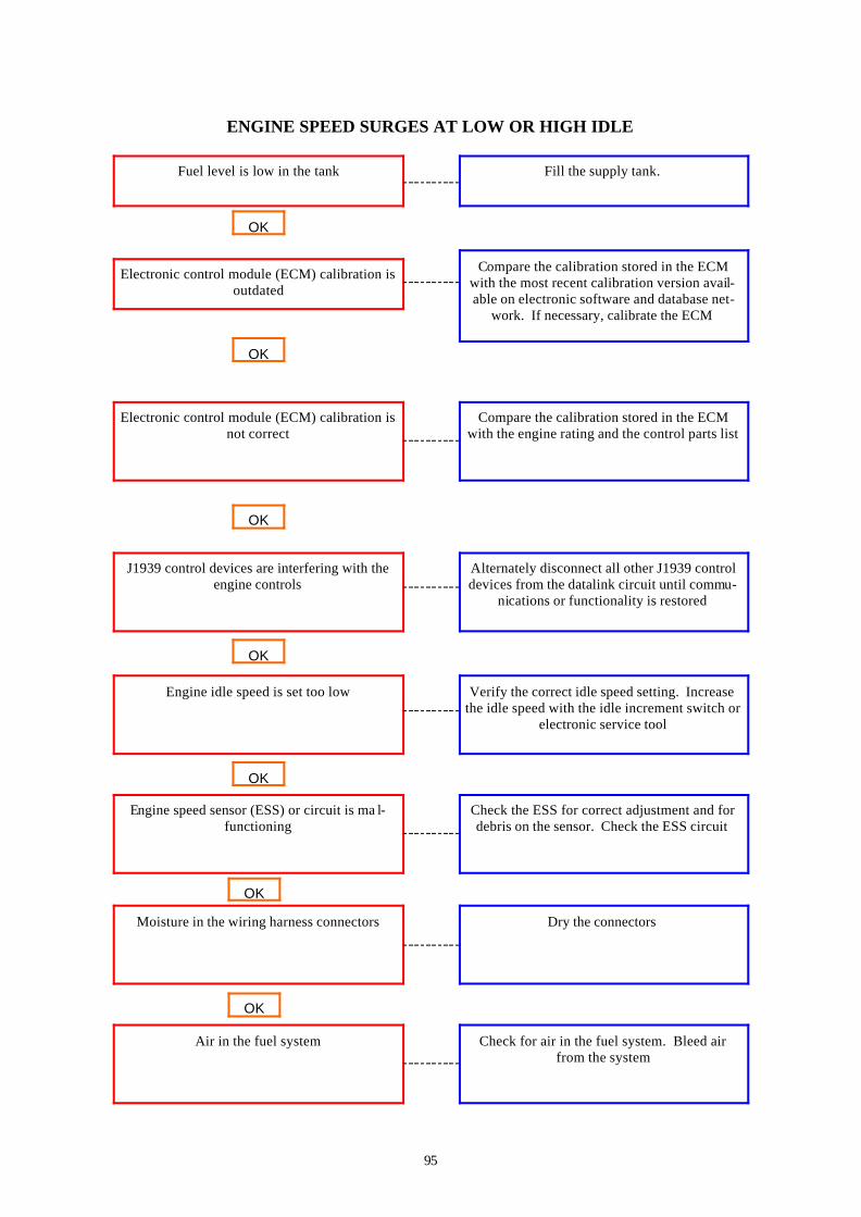
ENGINE SPEED SURGES AT LOW OR HIGH IDLE
Fuel level is low in the tank
Fill the supply tank.
Electronic control module (ECM) calibration is outdated
Compare the calibration stored in the ECM with the most recent calibration version avail-able on electronic software and database net-
work. If necessary, calibrate the ECM
OK
Electronic control module (ECM) calibration is not correct
Air in the fuel system
Moisture in the wiring harness connectors
Engine speed sensor (ESS) or circuit is ma l-functioning
J1939 control devices are interfering with the engine controls
Engine idle speed is set too low
OK
OK
OK
OK
Compare the calibration stored in the ECM with the engine rating and the control parts list
Alternately disconnect all other J1939 control devices from the datalink circuit until commu-
nications or functionality is restored
Verify the correct idle speed setting. Increase the idle speed with the idle increment switch or
electronic service tool
Check the ESS for correct adjustment and for debris on the sensor. Check the ESS circuit
Dry the connectors
Check for air in the fuel system. Bleed air from the system
OK
OK

96
ENGINE SPEED SURGES AT LOW OR HIGH IDLE (cont)
Fuel filter is plugged
Measure the fuel pressure before and after the fuel filter
Fuel inlet restriction
Check for fuel inlet restriction
OK
Fuel injection pump is malfunctioning Check CAPS gear pump output pressure
OK
Fuel injection pump is malfunctioning
Injector shim thickness is not correct
Injectors are not correct
Injector is malfunctioning
Fuel pressure sensor is malfunctioning
Fuel connector is leaking fuel
OK
OK
OK
OK
Check CAPS accumulator pressure
Using breakout cable, check the voltage of the fuel pressure sensor. If the voltage is outside the range on the wiring diagram, replace the
sensor
Perform the automated cylinder performance test to isolate the cylinder with the leaking fuel connector. Inspect the fuel connector and in-
jector for nicks and damage that can cause fuel leaks
Perform the automated cylinder performance test. Replace the injectors as necessary
Remove the injectors and compare the parts from the Control parts list. Replace the injec-
tors, if necessary.
Remove the injectors and verify the injector shim thickness
OK
OK

97
ENGINE SPEED SURGES AT LOW OR HIGH IDLE (cont)
Vibration damper is damaged.
Inspect the vibration damper
Fuel drain line restriction
Check the fuel drain lines for restriction. Clear or replace the fuel lines, check valves or tank
vents as necessary.
OK
Fuel grade is not correct for the application or the fuel quality is poor
Operate the engine from a tank of high quality fuel.
OK
Fuel injection pump is malfunctioning
Internal engine damage
Fuel injection pump is malfunctioning
Fuel injection pump is malfunctioning
Fuel injection pump is malfunctioning
OK
OK
OK
OK
Remove and inspect the rate shape snubber valve
Check the pump to engine timing
Remove and inspect the distributor snubber valve.
Replace the fuel injection pump
Analyse the oil and inspect the filters to locate an area or probable damage
OK

98
ENGINE SPEED SURGES UNDER LOAD OR IN OPERATING RANGE
Fuel level in low in the tank
Fill the supply tank
Fuel filter is plugged
Measure the fuel pressure before and after the fuel filter.
OK
Electronic control module (ECM) calibration is outdated
Compare the calibration stored in the ECM with the most recent calibration available on
the electronic software. If necessary, calibrate the ECM.
OK
Electronic control module (ECM) calibration is not correct
Fuel injection pump is malfunctioning
Fuel inlet restriction
Air in the fuel system
J1939 control devices are interfering with the engine controls
Moisture in the wiring harness connectors
OK
OK
OK
OK
Compare the calibration stored in the ECM with the engine rating and control parts list
Alternately disconnect all other J1939 control devices from the datalink circuit until commu-
nications or functionality is restored.
Dry the connectors
Check for air in the fuel system
Check for fuel inlet restriction
Check CAPS gear output pressure
OK
OK

99
ENGINE SPEED SURGES UNDER LOAD OR IN OPERATING RANGE (cont)
Fuel injection pump is malfunctioning
Check CAPS accumulator pressure.
Fuel pressure sensor is malfunctioning
Using breakout cable part no 3162982 (Cummins) check the voltage of the fuel pres-sure sensor. If voltage is outside of the range on the wiring diagram. Replace the sensor.
OK
Fuel connector is leaking fuel
Fuel injection pump is malfunctioning
Fuel drain line restriction
Injector shim thickness is not correct
Injector is malfunctioning
Injectors are not correct
OK
OK
OK
OK
Perform the automated cylinder performance test to isolate the cylinder with the leaking fuel connector. Inspect the fuel connector and in-jector for nicks or damage that can cause fuel
leaks
Perform the automated cylinder performance test. Replace the injectors as necessary.
Remove the injectors and compare the part numbers
Remove the injectors and verify the shim thic k-ness
Check the fuel drain lines for restriction. Clear or replace the fuel line, check valves or tank
vents as necessary.
Check pump to engine timing
OK
OK

100
ENGINE SPEED SURGES UNDER LOAD OR IN OPERATING RANGE (cont)
Fuel injection pump is malfunctioning
Remove and inspect the rate shape snubber valve
Fuel injection pump is malfunctioning
Remove and inspect the distribution snubber
OK
Fuel injection pump is malfunctioning
Replace the fuel injection pump
OK
Internal engine damage
OK
Analyse the oil and inspect the filters to locate an area of probable damage

101
ENGINE VIBRATION EXCESSIVE
Engine idle speed is set too low
Verify the correct idle speed setting. Increase the idle speed setting with the idle increment
switch or electronic service tool.
Engine mounts are worn, damaged or not cor-rect.
Check the engine mounts
OK
Fan is loose, damaged or not balanced Check the fan.
OK
Flywheel housing not aligned correctly
Flywheel or flexplate capscrews are loose or broken
Vibration damper is damaged
OK
OK
OK
Check the flywheel housing alignment
Check the flywheel or flexplate
Inspect the vibration damper

102
ENGINE WILL NOT CRANK OR CRANKS SLOWLY
Batteries are cold
Check the battery heater
Battery cables or connectors are loose
Check the battery cables and connectors
OK
Battery cables are no the correct length or gauge
Replace the battery cables with larger gauge or shorter length cables.
OK
Battery voltage is low
Lubricating oil level is above specification
Hydraulic lock in cylinder
Lubricating oil is below specification
Starting circuit components are malfunctioning
Lubricating oil does not meet specifications for operating conditions
OK
OK
OK
OK
Check the batteries and unswitched battery supply circuit
Check the starting circuit components
Change the oil and filters. Use only oil recom-mended by Ingersoll-Rand
Install an oil pan heater or drain the oil and fill the system with warm oil.
Remove the injectors and rotate the crankshaft. Look for the source of fluid in the cylinder
Check the oil. Verify the dipstick calibration and oil pan capacity. Fill the system to the
specified level.

103
ENGINE WILL NOT SHUT OFF
Keyswitch circuit is malfunctioning
Check the unit keyswitch circuit
Engine is running on fumes drawn into the air intake
Check the air intake ducts. Locate and isolate the source of the fumes. Repair as necessary
OK
Fuel injection pump is malfunctioning Perform ICV solenoid click test
OK
Electronic control module (ECM) is malfunc-tioning
Fuel injection pump is malfunctioning
OK
OK
Replace ECM
Remove and test the fuel injection pump. Re-place the pump if necessary.
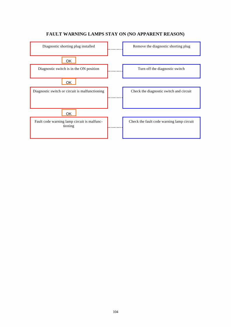
104
FAULT WARNING LAMPS STAY ON (NO APPARENT REASON)
Diagnostic shorting plug installed
Remove the diagnostic shorting plug
Diagnostic switch is in the ON position
Turn off the diagnostic switch
OK
Diagnostic switch or circuit is malfunctioning Check the diagnostic switch and circuit
OK
Fault code warning lamp circuit is malfunc-tioning
OK
Check the fault code warning lamp circuit

105
FAULT CODE WARNING LAMPS DO NOT ILLUMINATE
Keyswitch is in the OFF position
Turn the keyswitch to the ON position
Fault code warning lamps are burnt out
Check the warning lamps for voltage. Replace bulbs if necessary
OK
Battery voltage supply to the electronic control module (ECM) is low or interrupted or open.
Check the battery connections. Check the fuses and the unswitched battery supply circuit
OK
Fault code warning lamp is malfunctioning
Keyswitch circuit is malfunctioning
OK
OK
Check fault code warning lamp warning circuit
Check the keyswitch circuit
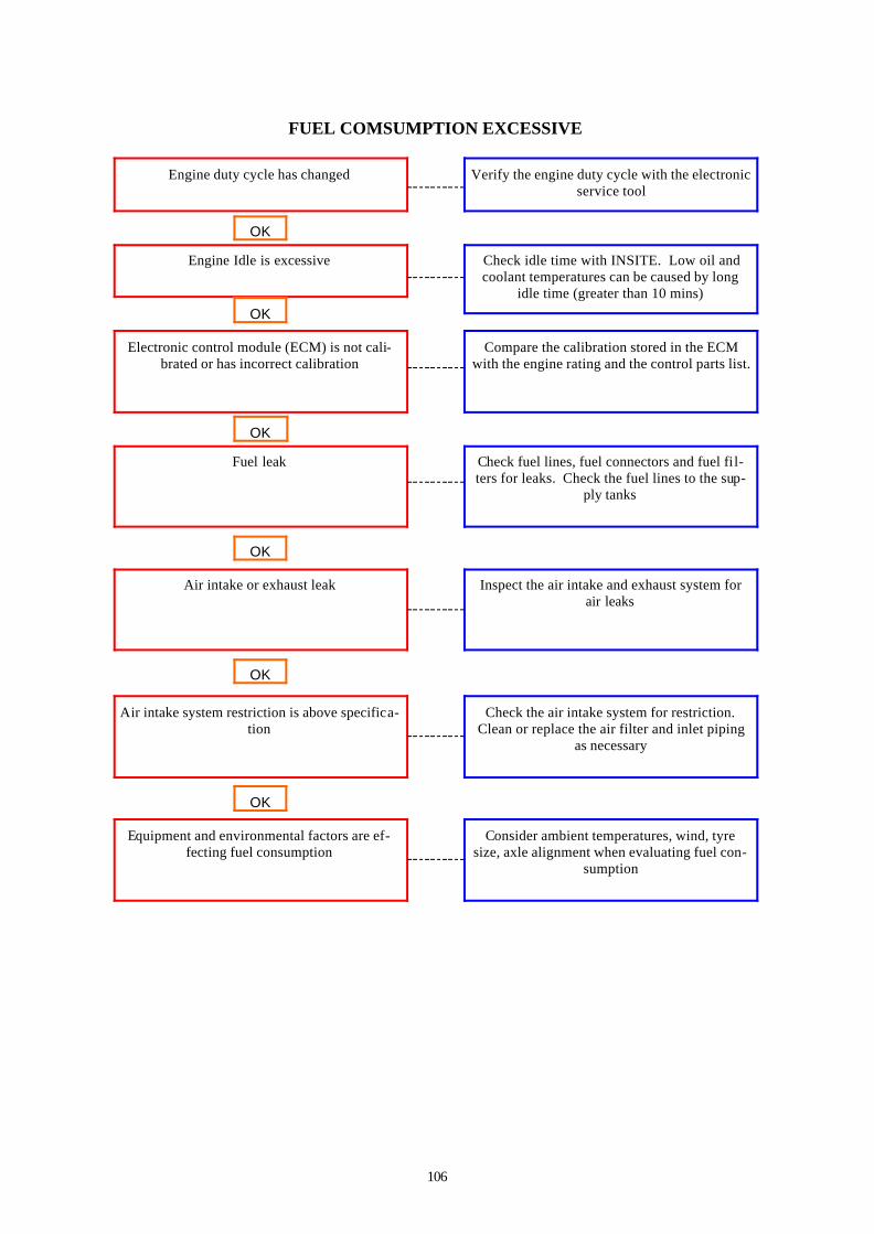
106
FUEL COMSUMPTION EXCESSIVE
Engine duty cycle has changed
Verify the engine duty cycle with the electronic service tool
Engine Idle is excessive
Check idle time with INSITE. Low oil and coolant temperatures can be caused by long
idle time (greater than 10 mins)
OK
Electronic control module (ECM) is not cali-brated or has incorrect calibration
Compare the calibration stored in the ECM with the engine rating and the control parts list.
OK
Fuel leak
Equipment and environmental factors are ef-fecting fuel consumption
Air intake or exhaust leak
Air intake system restriction is above specifica-tion
OK
OK
OK
OK
Check fuel lines, fuel connectors and fuel fi l-ters for leaks. Check the fuel lines to the sup-
ply tanks
Inspect the air intake and exhaust system for air leaks
Check the air intake system for restriction. Clean or replace the air filter and inlet piping
as necessary
Consider ambient temperatures, wind, tyre size, axle alignment when evaluating fuel con-
sumption

107
FUEL IN COOLANT Cause Correction
Cylinder head is cracked or porous
Pressure test the cylinder head
Bulk coolant supply is contaminated
Check the bulk coolant supply. Drain the cool-ant and replace with non– contaminated cool-
OK

108
FUEL IN THE LUBRICATING OIL
Engine idle time is excessive
Low oil and coolant temperatures can be caused by long idle time (greater than 10 mins)
Shut off the engine rather than idle for long periods of time. If idle time is necessary, raise
the idle speed
Injector ‘O’ rings are damaged or missing Remove and check the injectors. Replace the injector ‘O’ rings
OK
Injector is malfunctioning
Bulk oil supply is contaminated
Cylinder head is cracked or porous
Fuel injection pump is malfunctioning
Fuel injection pump is malfunctioning
Fuel injection pump is malfunctioning
OK
OK
OK
OK
Perform the automated cylinder performance test. Replace the injectors as necessary
Inspect the cam housing for cracks and damage
Replace the accumulator module
Inspect the injection pump gear module oil seal. Replace gear pump module if there are
signs or leakage
Pressure test the cylinder head
Check the bulk oil supply. Drain the oil and replace with non-contaminated oil Replace the
filters
OK
OK

109
INTAKE MANIFOLD AIR TEMPERATURE IS ABOVE SPECIFICATION
Charge air cooler fins, radiator fins or air con-ditioner condenser fins are damaged or ob-
structed with debris
Inspect the charge air cooler, air conditioner condenser and radiator fins. Clean, if neces-
sary.
Fan drive belt is loose Check the belt tension and tighten if necessary
OK
Fan drive belt is broken
Intake manifold pressure sensor is malfunction-ing
Fan drive or fan controls are malfunctioning
Exhaust system leaking hot air into the engine compartment
Fan shroud is damaged or missing or the air re-circulation baffles are damaged or missing
Radiator shutters are not opening completely
OK
OK
OK
OK
Check the fan drive belt and replace if neces-sary
Inspect the shroud and the re-circulation baf-fles. Repair, replace or install as necessary
Inspect the radiator shutters. Repair or replace if necessary
Check the exhaust plumbing for leaks or bro-ken components
Check the fan drive and couplings
Check the intake manifold pressure sensor.
OK
OK

110
INTAKE MANIFOLD AIR TEMPERATURE ABOVE SPECIFICATION (cont) Cause Correction
Fan is not adequate size for the application
Verify the fan is the correct size
Intake manifold temperature gauge is malfunc-tioning
Test the temperature gauge
OK

111
INTAKE MANIFOLD PRESSURE (BOOST) IS BELOW NORMAL
Air intake or exhaust leaks
Inspect the air intake and exhaust for leaks
Air intake restriction is above specification
Check the air intake for restriction. Clean or replace the air filter and inlet piping as neces-
sary
OK
Charge air cooler is restricted or leaking Inspect the charge air cooler for restrictions or leaks
OK
Exhaust system restriction is above specifica-tion
OK
Check the exhaust system for restrictions

112
LUBRICATING OIL CONSUMPTION EXCESSIVE
Lubricating oil does not meet specifications for operating conditions
Change the oil and filters. Use recommended IR oil
Lubricating oil drain interval is excessive
Verify the correct lubricating oil drain interval
OK
Lubricating oil leak (external) Inspect the engine for external oil leaks. Tighten the capscrews, pipe plugs and fitting.
Replace gaskets, if necessary
OK
Verify the oil consumption rate
Internal engine damage
Piston or piston rings are worn or damaged
Piston rings are not seated correctly (after an engine re-build or piston installation
Lubricating oil is leaking
Lubricating oil level is above specification
OK
OK
OK
OK
Check the amount of oil added verses hours run on unit
Check the lubricating oil cooler for coolant leaks
Check the oil level. Verify the dipstick calibra-tion and oil pan capacity. Fill the system to the
specified level.
Check blowby. If blowby is excessive, check piston rings for correct seating
Check air intake system for leaks. Check the pistons and piston rings for wear and damage
Analyse the oil and inspect the filters to locate an area of probable damage
OK
OK

113
LUBRICATING OIL CONTAMINATED
Bulk oil supply is contaminated
Check the bulk oil supply. Drain the oil and replace with non—contaminated oil. Replace
oil filters
Identify lubricating oil contamination
Perform an oil analysis to determine contami-nants
OK
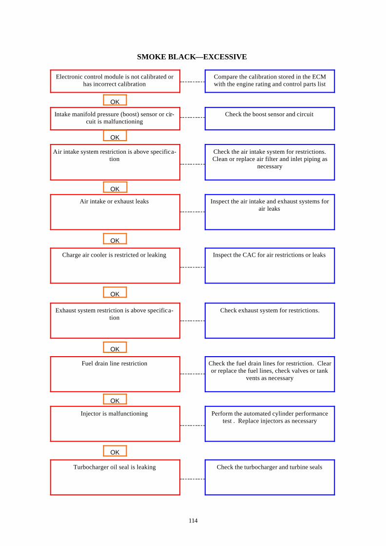
114
SMOKE BLACK—EXCESSIVE
Electronic control module is not calibrated or has incorrect calibration
Compare the calibration stored in the ECM with the engine rating and control parts list
Intake manifold pressure (boost) sensor or cir-cuit is malfunctioning
Check the boost sensor and circuit
OK
Air intake system restriction is above specifica-tion
Check the air intake system for restrictions. Clean or replace air filter and inlet piping as
necessary
OK
Air intake or exhaust leaks
Turbocharger oil seal is leaking
Injector is malfunctioning
Fuel drain line restriction
Charge air cooler is restricted or leaking
Exhaust system restriction is above specifica-tion
OK
OK
OK
OK
Inspect the air intake and exhaust systems for air leaks
Inspect the CAC for air restrictions or leaks
Check exhaust system for restrictions.
Check the fuel drain lines for restriction. Clear or replace the fuel lines, check valves or tank
vents as necessary
Perform the automated cylinder performance test . Replace injectors as necessary
Check the turbocharger and turbine seals
OK
OK

115
SMOKE, BLACK—EXCESSIVE (cont)
Turbocharger wheel clearance is out of specifi-cation
Check radial bearing clearance and axle clear-ance. Inspect the turbocharger. Repair or re-
place as necessary
Overhead adjustments are not correct
Measure and adjust the overhead settings
OK
Fuel grade is not correct for the application or the fuel quality is poor
Operate engine from a tank of high quality fuel
OK
Injector shim thickness is not correct
Internal engine damage
Fuel injection pump is malfunctioning
Fuel injection pump is malfunctioning
Fuel injection timing is not correct
Raw fuel in the intake manifold
OK
OK
OK
OK
Remove the injectors and verify the injector shim thickness
Check the fuel pump timing
Check the intake manifold for fuel. Locate the fuel source and repair as necessary
Check CAPS accumulator pressure
Replace the injection control valve module
Analyse the oil and inspect the filters to locate an area of probable damage
OK
OK

116
SMOKE, WHITE — EXCESSIVE
Electronic control module (ECM) is not cali-brated or has incorrect calibration
Compare the calibration stored in the ECM with the engine rating and the control parts list.
If necessary, calibrate the ECM.
Engine is cold Allow engine to warm to operating tempera-ture.
OK
Engine is operating at low ambient temperature
Injectors shim thickness is not correct
Injector is malfunctioning
Intake manifold pressure sensor is malfunction-ing
Starting aid is necessary for cold weather, or starting aid is malfunctioning
Coolant temperature sensor is malfunctioning
OK
OK
OK
OK
Check the shutters and engine compartment air
Check for correct operation of the starting aid.
Check the coolant temperature sensor.
Check the intake manifold pressure sensor
Perform the automated cylinder performance test
Remove the injectors and verify the injector shim thickness
OK
OK

117
SMOKE, WHITE — EXCESSIVE (cont)
Fuel grade is not correct for the application or the fuel quality is poor.
Operate the engine from a tank of high quality fuel
Fuel filter is plugged
Measure the fuel pressure before and after the fuel filter
OK
Air intake system restriction is above specifica-tion
Check the air intake system for restriction. Clean or replace the air filter and inlet piping
as necessary
OK
Air intake or exhaust leaks
Injectors are not correct
Raw fuel in the intake manifold
Overhead adjustments are not correct
Charge-air cooler (CAC) is restricted or leak-ing
Fuel drain line restriction
OK
OK
OK
OK
Inspect the air intake or exhaust systems for air leaks.
Inspect the CAC for air restrictions or leaks
Check the fuel drain lines for restriction. Clear or replace the fuel lines, check valves or tank
vents as necessary.
Measure and adjust the overhead settings
Check the intake manifold for fuel. Locate the fuel source and repair as necessary
Remove the injectors and compare the part numbers to the control parts list. Replace the
injectors if necessary
OK
OK
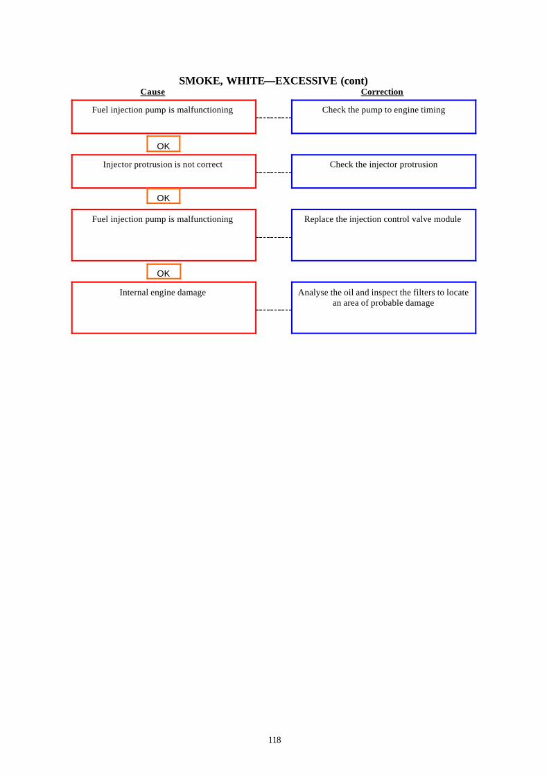
118
SMOKE, WHITE—EXCESSIVE (cont) Cause Correction
Fuel injection pump is malfunctioning
Check the pump to engine timing
Injector protrusion is not correct
Check the injector protrusion
OK
Fuel injection pump is malfunctioning Replace the injection control valve module
OK
Internal engine damage
OK
Analyse the oil and inspect the filters to locate an area of probable damage
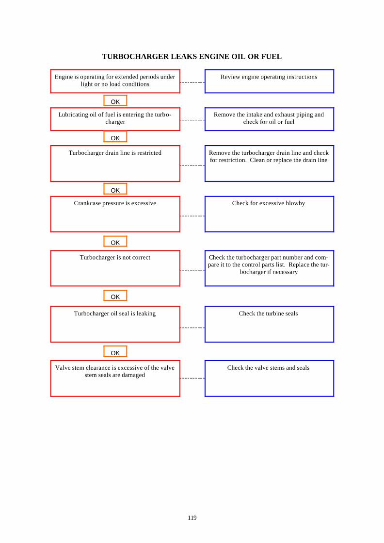
119
TURBOCHARGER LEAKS ENGINE OIL OR FUEL
Engine is operating for extended periods under light or no load conditions
Review engine operating instructions
Lubricating oil of fuel is entering the turbo-charger
Remove the intake and exhaust piping and check for oil or fuel
OK
Turbocharger drain line is restricted Remove the turbocharger drain line and check for restriction. Clean or replace the drain line
OK
Crankcase pressure is excessive
Valve stem clearance is excessive of the valve stem seals are damaged
Turbocharger is not correct
Turbocharger oil seal is leaking
OK
OK
OK
OK
Check for excessive blowby
Check the turbocharger part number and com-pare it to the control parts list. Replace the tur-
bocharger if necessary
Check the turbine seals
Check the valve stems and seals

120
THIS PAGE IS LEFT INTENTIONALLY BLANK

121
ADJUSTMENT, REPAIR AND REPLACEMENT
ALTERNATOR Install Preparatory Remove
BELT TENSIONER, AUTOMATIC Install Preparatory Remove
CHARGE-AIR COOLER (CAC) General Information Leak test Pressure Test Temperature Differential Test
COOLANT THERMOSTAT Clean Install Preparatory Remove
DRIVE BELT, WATER PUMP Install Remove
FAN SPACER AND PULLEY Install Preparatory Remove
STARTER MOTOR Install Preparatory Remove

122
THIS PAGE IS LEFT INTENTIONALLY BLANK

123
Drive Belt, Water Pump Remove 3/8-inch Square Drive Lift the tensioner to remove the drive belt. NOTE: The belt tensioner winds in the direction that the spring tang is bent over the tensioner body. To loosen the tension on the belt, rotate the tensioner to wind the spring tighter. Applying excessive force in the oppo-site direction of the wind-up or after the tensioner has been wound-up to the positive stop can cause the ten-sioner arm to break. Install 3/8-inch Square Drive The belt tensioner is spring-loaded and must be pivoted away from the drive belt. Pivoting in the wrong direction can damage the belt tensioner. Belt Tensioner, Automatic Preparatory Remove the drive belt

124
Remove 3/8-inch Square Drive The belt tensioner is spring-loaded and must be pivoted away from the drive belt. Pivoting in the wrong direction can damage the belt tensioner. Lift the belt tensioner to relive tension in the belt, and remove the belt. 15 mm Remove the capscrew and belt tensioner from the bracket. Install 15 mm Install the belt tensioner and capscrews. Torque Value: 43Nm (32ft- lb) 3/8-Inch Square Drive Lift and hold the tensioner. Install the drive belt, and release the tensioner. Service Tip. If difficulty is experienced installing the drive belt, or if the belt seems too short, position the belt over the grooved pulleys first; then, while holding the tensioner up, slide the belt over the water pump pulley.

125
Fan Spacer and Pulley Preparatory Remove the drive belt Service Tip: Loosen the capscrews be-fore removing the belt, and tighten the capscrews after the belt is installed. Remove 3/8-Inch Square Drive The belt tensioner is spring-loaded and must be pivoted away from the drive belt. Pivoting in the wrong direction can result in damage to the belt ten-sioner. Lift the tensioner to relive tension in the belt. Remove the belt. Remove the fan capscrews, fan and spacer. Remove the fan pulley. Install 13 mm Install the fan pulley. Install the spacer, fan and fan capscrews. Torque Value: 24Nm (18ft- lb)

126
3/8-Inch Square Drive Lift the tensioners and install the belt. Service Tip: If difficulty is experienced installing the drive belt, or if the belt seems too short, position the belt over the grooved pulleys first; then, while holding the tensioner up, slide the belt over the water pulley. Coolant Thermostat Preparatory Coolant is toxic. If not reused, dispose of in accordance with local environ-mental regulations. Do not remove the pressure cap from a hot engine. Wait until the coolant tem-perature is below 50ºC (122ºF) before removing the pressure cap. Heated coolant spray or steam can cause per-sonal injury. Drain the coolant from the radiator. Disconnect the upper radiator hose. Remove 10 mm Remove the water outlet tube capscrews and water outlet tube. Remove the thermostat. Clean Do not let any debris fall into the ther-mostat cavity when cleaning the sur-faces. Failure to do so will result in en-gine damage. Clean all mating surfaces.

127
Install Install the new thermostat into the ther-mostat housing. Make sure that the top and bottom o-rings are in place. 10 mm Install the water outlet tube and cap-screws. Torque Value: 24 Nm (18 ft- lb) Always vent the engine and aftercooler during filling to remove air from the coolant system, or overheating will re-sult. Fill the cooling system. Operate the engine, and check for leaks. Charge-Air Cooler (CAC) Pressure Test Install the pressure gauge into the fitting in the turbocharger. Install another pressure gauge into the intake manifold. Operate the engine at rated rpm and load. Record the readings on the two gauges. If the differential pressure is greater than 50 kPa (7 psi). Check the charge-air cooler (CAC) for plugging. Clean or re-place if necessary.
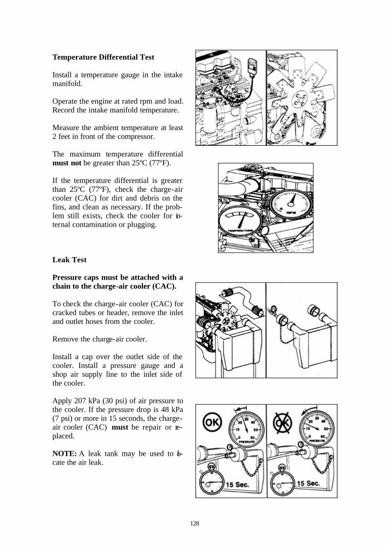
128
Temperature Differential Test Install a temperature gauge in the intake manifold. Operate the engine at rated rpm and load. Record the intake manifold temperature. Measure the ambient temperature at least 2 feet in front of the compressor. The maximum temperature differential must not be greater than 25ºC (77ºF). If the temperature differential is greater than 25ºC (77ºF), check the charge-air cooler (CAC) for dirt and debris on the fins, and clean as necessary. If the prob-lem still exists, check the cooler for in-ternal contamination or plugging. Leak Test Pressure caps must be attached with a chain to the charge-air cooler (CAC). To check the charge-air cooler (CAC) for cracked tubes or header, remove the inlet and outlet hoses from the cooler. Remove the charge-air cooler. Install a cap over the outlet side of the cooler. Install a pressure gauge and a shop air supply line to the inlet side of the cooler. Apply 207 kPa (30 psi) of air pressure to the cooler. If the pressure drop is 48 kPa (7 psi) or more in 15 seconds, the charge-air cooler (CAC) must be repair or re-placed. NOTE: A leak tank may be used to lo-cate the air leak.

129
The charge-air cooler (CAC) must be cleaned following any turbocharger or air cleaner failure. Debris trapped in the charge-air cooler (CAC), if not cleaned, can cause internal engine damage. Starting Motor Preparatory Disconnect the ground cable from the battery terminal. Identify each electrical wire with a tag indicating location. Remove Remove the electrical connections from the batteries, negative (-) cable first. Remove the electrical connections from the starter motor, and identify each wire with a tag indicating location. 10 mm Remove the three capscrews and the starter motor. Install 10 mm Install the starter motor in the reverse or-der of removal. Connect all the cables. Connect the nega-tive (-) cable last Torque Value: 43 Nm (32 ft- lb)
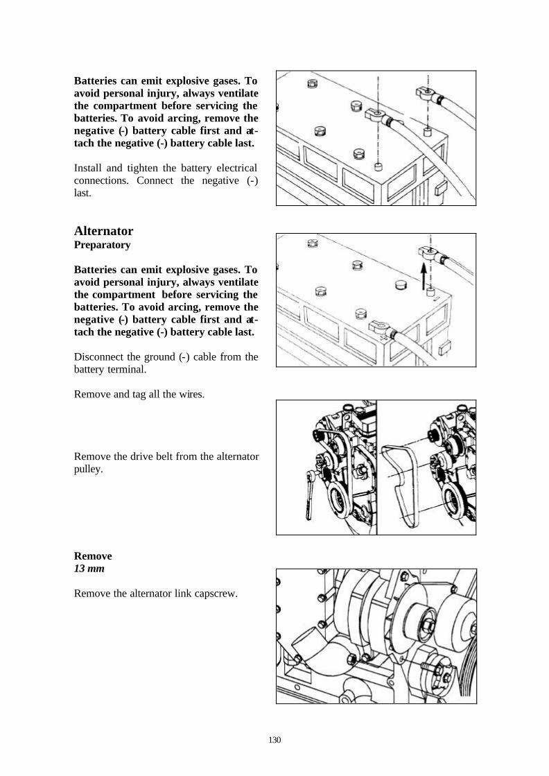
130
Batteries can emit explosive gases. To avoid personal injury, always ventilate the compartment before servicing the batteries. To avoid arcing, remove the negative (-) battery cable first and at-tach the negative (-) battery cable last. Install and tighten the battery electrical connections. Connect the negative (-) last. Alternator Preparatory Batteries can emit explosive gases. To avoid personal injury, always ventilate the compartment before servicing the batteries. To avoid arcing, remove the negative (-) battery cable first and at-tach the negative (-) battery cable last. Disconnect the ground (-) cable from the battery terminal. Remove and tag all the wires. Remove the drive belt from the alternator pulley. Remove 13 mm Remove the alternator link capscrew.
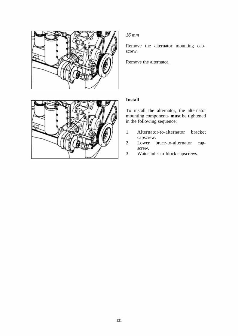
131
16 mm Remove the alternator mounting cap-screw. Remove the alternator. Install To install the alternator, the alternator mounting components must be tightened in the following sequence: 1. Alternator-to-alternator bracket
capscrew. 2. Lower brace-to-alternator cap-
screw. 3. Water inlet-to-block capscrews.

132
THIS PAGE IS LEFT INTENTIONALLY BLANK
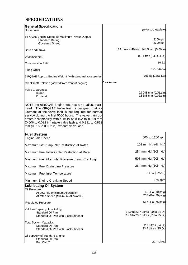
133
SPECIFICATIONS General Specifications Horsepower 6IRQ9AE Engine Speed @ Maximum Power Output:
Standard Rating Governed Speed
Bore and Stroke Displacement Compression Ratio Firing Order 6IRQ9AE Approx. Engine Weight (with standard accessories) Crankshaft Rotation (viewed from front of engine) Valve Clearance:
Intake Exhaust
(refer to dataplate)
2100 rpm 2300 rpm
114 mm ( 4.49 in) x 144.5 mm (5.69 in)
8.9 Litres (543 C.I.D.)
16.6:1
1-5-3-6-2-4
706 kg (1556 LB)
Clockwise
0.3048 mm (0.012 in) 0.5588 mm (0.022 in)
NOTE the 6IRQ9AE Engine features a no-adjust ove r-head. The 6IRQ9AE Valve train is designed that ad-justment of the valve lash is not required for normal service during the first 5000 hours. The valve train op-erates acceptability within limits of 0.152 to 0.559-mm (0.006 to 0.022 in) intake valve lash and 0.381 to 0.813 mm (0.015 to 0.032 in) exhaust valve lash.
Fuel System Engine Idle Speed Maximum Lift Pump Inlet Restriction at Rated Maximum Fuel Filter Outlet Restriction at Rated Minimum Fuel Filter Inlet Pressure during Cranking Maximum Fuel Drain Line Pressure Maximum Fuel Inlet Temperature Minimum Engine Cranking Speed
600 to 1200 rpm
102 mm Hg (4in Hg)
254 mm Hg (10in Hg)
508 mm Hg (20in Hg)
254 mm Hg (10in Hg)
71°C (160°F)
150 rpm
Lubricating Oil System Oil Pressure
At Low Idle (minimum Allowable) At rated Speed (Minimum Allowable)
Regulated Pressure Oil Pan Capacity, Low to High
Standard Oil Pan Standard Oil Pan with Block Stiffener
Total System Capacity: Standard Oil Pan Standard Oil Pan with Block Stiffener
Oil capacity of Standard Engine Standard Oil Pan Pan ONLY
69 kPa (10 psig) 207 kPa (30 psig)
517 kPa (75 psig)
18.9 to 22.7 Litres (20 to 24 Qt) 19.9 to 23.7 Litres (21 to 25 Qt)
22.7 Litres (24 Qt) 23.7 Litres (25 Qt)
22.7 Litres

134
Specifications
Cooling System
Coolant Capacity (Engine Only) 10.9 Litres (11.5 Qt)
Standard modulating Thermostat Range 84ºC - 91ºC (183ºF - 196ºF)
Maximum Allowable Operating Temperature 100ºC (212ºF)
Minimum Recommended Operating Temperature 70ºC (158ºF)
Minimum Recommended Pressure Cap 50 kPa (7 psi)
Air Intake System
Maximum Intake Restriction (Clean Air Filter Element) 254mm H2O (10.0in H2O)
Maximum Intake Restriction (Dirty Air Filter Element) 635mm H2O (25.0in H2O )
Exhaust System
Maximum Back Exhaust Pressure 76mm Hg (3in Hg)
Electrical System Recommended Battery Capacity
System Voltage
Ambient Temperature
-18ºC (0ºF) -29ºC (-20ºF)
Cold Cranking Amperes
Reserve Capacity (Minutes) (1)
Cold Cranking Amperes
Reserve Capacity (Minutes)
12 VDC 1500 360 1875 360
24 VDC (2) 750 180 900 180
1. The number of plates within a given battery size determines reserve capacity. Reserve capacity determines the length of time for which a battery at 27ºC (81ºF) can supply 25 amperes at 10.5 volts or greater. 2. The CCA ratings are based upon two 12 VDC batteries in series.

135
Batteries (Specific Gravity)
Specific Gravity at 27ºC (81ºF) State of Charge
1.260 to 1.280 100%
1.230 to 1.250 75%
1.200 to 1.220 50%
1.170 to 1.190 25%
1.110 to 1.130 Discharged
FUEL RECOMMENDATIONS AND SPECIFICATIONS Fuel Recommendations Do not mix gasoline, alcohol, or gasohol with diesel fuel. This mixture can cause an explosion. Due to the precise tolerances of diesel injection systems, it is extremely important that the fuel be kept clean and free of dirt or water. Dirt or water in the system can cause severe damage to both the fuel pump and the fuel injectors. Lighter fuels can reduce fuel economy and can cause damage the fuel injection pump. Ingersoll Rand Ltd. Recommends the use of ASTM No. 2D fuel. The use of No. 2D fuel will result in optimum engine performance. At operating temperatures below 0ºC (32ºF), acceptable performance can be obtained by using blends of No. 2D and No. 1D. The viscosity of the fuel must be kept above 1.3 cSt at 40ºc (104ºF) to provide adequate fuel system lubrication. The following chart lists alternate fuels for the 6IRQ9AE engine.
Acceptable substitutes Fuels - 6IRQ9AE
No. 1D Diesel (1) (2)
No. 2D Diesel
No. 1K Kerosene
Jet-A Jet-A1 JP-5 JP-8 Jet-B JP-4 CITE
OK OK OK OK OK OK OK NOT OK NOT OK NOT OK
1. Any adjustment to compensate for reduced performance with a fuel system using alternate fuel is not warrantable.
2. Winter blend fuels, such as those found at commercial fuel dispensing outlets, are combinations of No. 1D and No. 2D diesel and are acceptable.

136
THIS PAGE IS LEFT INTENTIONALLY BLANK

137
LUBRICATING OIL RECOMMENDATIONS AND SPECIFICATIONS
New Engine Break-in Oils A sulphated ash limit of 1.85 percent has been placed on all engine lubricating oils recommended for use in Ingersoll Rand. Higher ash oils can cause valve and / or pis-ton damage and lead to excessive oil consumption. The use of a synthetic-based oil does not justify extended oil change intervals. Ex-tended oil change intervals can decrease engine life due to factors such as corrosion, deposits, and wear. Special ‘break- in’ engine lubricating oils are not recommended for new or rebuilt Inger-soll Rand engines. Use the same kind of oil during the ‘break- in ‘ as used in normal oper-ating. Arctic Operation Engine Oil. If an engine is operated in ambient temperatures consistently below –23ºC (-9ºF), and there are no provisions to keep the engine warm when not in operation, use a synthetic CE / SF or higher API classification engine oil with adequate low temperature properties (such as 5W-20 or 5W-30). General Information The use of quality engine lubricating oils, combined with appropriate oil drain and filter change intervals, are critical factors in maintaining engine performance and durability. Ingersoll Rand Ltd recommends the use of a high-quality SAE 15W-40 multiviscosity heavy-duty engine oil, such as Ingersoll Rand Pro-Tec Engine Oil that meets the require-ment of the American Petroleum Institute (API) performance classification CG-4 or CH-4. NOTE: In areas where CG-4 or CH-4 lubricating oils are not available, CF-4 lubricating oil can be used, but the lubricating oil change interval must be reduced to 250 hours or 6 months. A sulphated ash limit of 1.0 mass percentage is suggested for optimum valve and piston deposit and oil consumption control, the sulphated ash must not exceed 1.85 mass per-cent.

138
The use of low-viscosity oils, such as 10W or 10W-30, can be used to aid in starting the engine and in providing suf-ficient oil flow at ambient temperatures below -5ºC (-23ºF). However, continu-ous use of low-viscosity oils can de-crease engine life due to wear. The API service symbols are shown in the accompanying illustration. The upper half of the symbol displays the appropri-ate oil categories. The lower half can contain a description of oil energy conserving features. The center section identifies the SAE oil viscosity grade. As the engine oil becomes contaminated, essential oil additives are depleted. Lu-bricating oils, protect the engine as long as these additives are functioning prop-erly. Progressive contamination between oil and filter change intervals is normal. The amount of contamination will vary depending on the operation of the engine, hours on the oil, fuel consumed, and new oil added. Extending oil and filter change intervals beyond the recommendations will de-crease engine life due to factors such as corrosion, deposits and wear. Ingersoll Rand Filter Specification Ingersoll Rand CPN: 22177737

139
COOLANT RECOMMENDATIONS AND SPECIFICATIONS
Fully Formulated Coolant / Antifreeze Ingersoll Rand Ltd. recommends using either a 50/50 mixture of high-quality water and fully formulated antifreeze or fully formulated coolant when filling the cooling system. The fully formulated an-tifreeze or coolant must meet TMC RP 329 or TMC RP 330 specifications. High-quality water is important for cooling system performance. Excessive levels of calcium and magnesium con-tribute to scaling problems, and exces-sive levels of chlorides and sulphates cause cooling system corrosion. Fully formulated antifreeze must be mixed with high-quality water at a 50/50 ratio (40- to 60-percent working range). A 50/50 mixture of antifreeze and water has a -36ºC (-33ºF) freezing point and a 110ºC (230ºF) boiling point. The actual lowest freezing point of ethylene glycol antifreeze is at 68 percent. Using higher concentrations of antifreeze will raise the freezing point of the solution and in-crease the possibility of a silicate gel problem. A refractometer must be used to measure the freezing point of the coolant accu-rately. Do not use a floating ball hydrometer. Use of a floating ball hydrometer can give an incorrect reading.
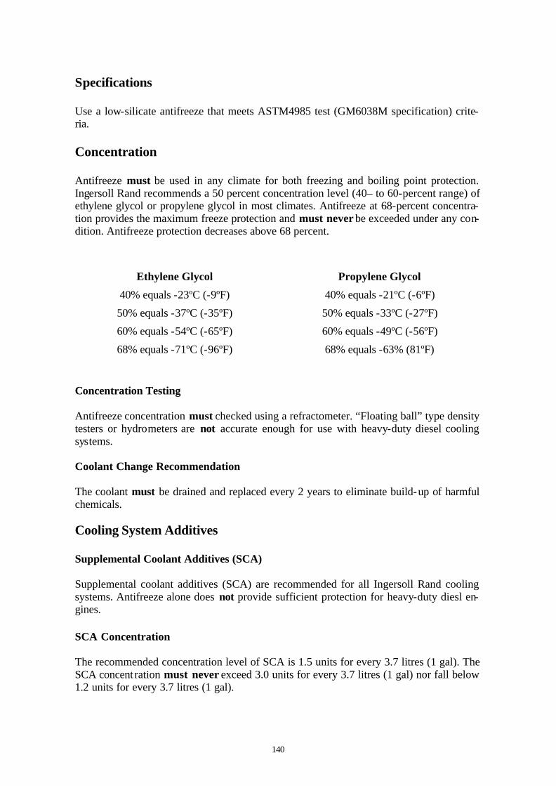
140
Specifications Use a low-silicate antifreeze that meets ASTM4985 test (GM6038M specification) crite-ria. Concentration Antifreeze must be used in any climate for both freezing and boiling point protection. Ingersoll Rand recommends a 50 percent concentration level (40– to 60-percent range) of ethylene glycol or propylene glycol in most climates. Antifreeze at 68-percent concentra-tion provides the maximum freeze protection and must never be exceeded under any con-dition. Antifreeze protection decreases above 68 percent.
Ethylene Glycol Propylene Glycol
40% equals -23ºC (-9ºF) 40% equals -21ºC (-6ºF)
50% equals -37ºC (-35ºF) 50% equals -33ºC (-27ºF)
60% equals -54ºC (-65ºF) 60% equals -49ºC (-56ºF)
68% equals -71ºC (-96ºF) 68% equals -63% (81ºF)
Concentration Testing Antifreeze concentration must checked using a refractometer. “Floating ball” type density testers or hydrometers are not accurate enough for use with heavy-duty diesel cooling systems. Coolant Change Recommendation The coolant must be drained and replaced every 2 years to eliminate build-up of harmful chemicals. Cooling System Additives Supplemental Coolant Additives (SCA) Supplemental coolant additives (SCA) are recommended for all Ingersoll Rand cooling systems. Antifreeze alone does not provide sufficient protection for heavy-duty diesl en-gines. SCA Concentration The recommended concentration level of SCA is 1.5 units for every 3.7 litres (1 gal). The SCA concent ration must never exceed 3.0 units for every 3.7 litres (1 gal) nor fall below 1.2 units for every 3.7 litres (1 gal).
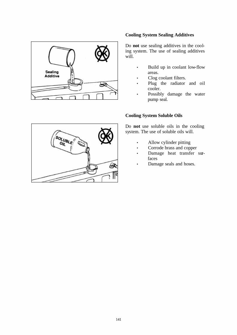
141
Cooling System Sealing Additives Do not use sealing additives in the cool-ing system. The use of sealing additives will.
• Build up in coolant low-flow areas.
• Clog coolant filters. • Plug the radiator and oil
cooler. • Possibly damage the water
pump seal. Cooling System Soluble Oils Do not use soluble oils in the cooling system. The use of soluble oils will.
• Allow cylinder pitting • Corrode brass and copper • Damage heat transfer sur-
faces • Damage seals and hoses.

142
THIS PAGE IS LEFT INTENTIONALLY BLANK

143
Engine Component Torque Values
Torque Table
Component Wrench Size Torque Value
N•m ft- lb In- lb
Aftercooler Mounting 10 mm 24 18
Aftercooler Water Hose Clamp 8 mm 5 41
Alternator Link (Delco 10-15 SI) 13 mm 24 18
Alternator Link (Delco 20-27 SI) 3/4 in 43 32
Alternator Mtg. Bolt 10-15SI 15 mm 43 32
Alternator Mtg. 27 SI 18 mm 77 57
Alternator Support (Upper) 10 mm 24 18
Belt Tensioner Flat Bracket Allen 5 mm 24 18
Belt Tensioner Mounting 15 mm 43 32
Crankshaft Damper And Pulley 15 mm 137 101
Crossover Clamp 5/16 in 5 44
Tee-Bolt-Type Clamp 11 mm 8 71
Exhaust Outlet Pipe, V-Band Clamp 7/16 in 8 71
Fan Bracket Mounting 10 mm 24 18
Fan Pulley 10 mm 24 18
Fan Pulley 13 mm 43 32
Fuel Filter 75 to 85 mm Install as specified by filter manufacturer
Fuel Filter Adapter Nut 24 mm 32 24
Lubricating Oil Filter 75 to 85 mm 3/4 of a turn after contact
Lubricating Oil Cooler Assembly 10 mm 24 18
Lubricating Oil Pan Drain Plug 17 mm 80 59
Lubricating Oil Pan Heater Plug 27 mm 80 59
Starter Mounting 10 mm 43 32
Thermostat Housing 10 mm 24 18
Water Inlet Connection 15 mm 43 32
Water Pump Mounting 13 mm 24 18
Rocker Lever (Valve) Cover 15 mm 12 106
Water-In-Fuel Sensor 19 mm Hand-tighten

144
THIS PAGE IS LEFT INTENTIONALLY BLANK

145
IR CPN DESCRIPTION
15900525 THERMOSTAT
15901945 PRESSURE SWITCH
15902430 INJECTOR
22113039 FAN BELT
22177711 FUEL FILTER
22177737 OIL FILTER ENG
36841138 TEMPERATURE SENDER
36868156 WATER FILTER
36870608 OIL PRESSURE SENDER
36896892 PRESSURE REGULATOR
89288971 AIR FILTER MAIN
89288989 AIR FILTER SAFETY
89311716 PROTEC ENGINE OIL
SERVICE PARTS LIST

146
THIS PAGE IS LEFT INTENTIONALLY BLANK

147
Ingersoll-Rand, through its distributor, war-rants that each item of equipment manufac-tured by it and delivered hereunder to the ini-tial user will be free of defects in material and workmanship for a period of three (3) months from initial operation or six (6) months from the date of shipment to the initial user, which-ever occurs first. With respect to the following types of equip-ment, the warranty period enumerated below will apply in lieu of the foregoing warranty period. A. Aftercoolers - The earlier of nine (9)
months from date of shipment to or six (6) months from initial operation by ini-tial user.
B. Portable Compressors, Portable Ge n-
erator Sets - 9 Kva through to 550 Kva, Portable Light Towers and Air Dryers - The earlier of twelve (12) months from shipment to or the accu-mulation of 2,000 hours of operation by the initial user. 2.5 Kva Through to 8 Kva– The ear-lier of twelve (12) months from ship-ment to or the accumulation of 2,000 hours of operation by the initial user. Ingersoll-Rand will provide a new part or repaired part, at it’s sole discretion, in place of any part which is found to be defective in material or workmanship during the period described above. La-bor cost to replace the part is the re-sponsibility of the initial user.
C Portable Compressor Air Ends - The
earlier of twenty-four (24) months from shipment to or the accumulation of 4,000 hours of operation by the initial user. For Air Ends, the warranty against defects will include replacement of the complete Air End, provided the original Air End is returned assembled and all original seals are intact
C Portable Compressor Airend Limited Extended Warranty - The earlier of sixty (60) months from shipment to or the accumulation of 10,000 hours of op-eration by the initial user. This extended warranty is limited to defects in design or defective material or workmanship in ro-tors, housings, bearings and gears and provided all the following conditions are met:
1. The original air end is returned as-sembled and all original seals are intact.
2. Continued use of genuine Ingersoll-Rand parts, fluids, oil and filters.
3. Maintenance is performed at pre-scribed intervals by authorized and properly trained service engineers.
D Generator Alternator - 9 Kva through
to 550 Kva, The earlier of twenty-four (24) months from shipment to or the ac-cumulation of 4,000 hours of operation by the initial user. 2.5 Kva Through to 8 Kva - The earlier of twelve (12) months from shipment to or the accumulation of 2,000 hours of op-eration by the initial user.
E Portable Light Tower Alternator - The
earlier of twelve (12) months from ship-ment to or the accumulation of 2,000 hours of operation by the initial user. Light Source model only, the earlier of twenty-four (24) months from shipment to or the accumulation of 4,000 hours of operation by the initial user.
F Ingersoll-Rand Engines - The earlier of
twenty-four (24) months from shipment to or the accumulation of 4,000 hours of operation by the initial user.
G Ingersoll-Rand Platinum Drive Train Lim-
ited Extended Warranty – Platinum drive train refers to the Ingersoll-Rand Engine and Airend combination. The earlier of sixty (60) months from shipment to, or the accumula-tion of 10,000 hours of operation by the ini-tial user. The starter, alternator, fuel injec-tion system and all electrical components are
WARRANTY

148
excluded from this extended warranty. The airend seal and drive coupling are included in the warranty but airend drive belts are excluded. This limited extended warranty is automatically available when meeting the following conditions are met: 1. The original airend is returned as-
sembled and unopened. 2. Continued use of genuine Ingersoll-
Rand parts, fluids, oil and filters. 3. Maintenance is performed at pre-
scribed intervals by authorized and properly trained service engineers.
Ingersoll-Rand shall be provided with such information as it requires to confirm that these conditions have been complied with. H 1. Construction Tools, (Portable
Power range only) – Twelve (12) months from shipment to initial user. Ingersoll-Rand will provide a new part or repaired part, at it’s sole discretion, in place of any part which is found to be defective in material or workman-ship during the period described above. Labor cost to replace the part is the re-sponsibility of the initial user.
2. Construction Tools Limited Ex-tended Warranty, (Portable Power range only). Thirty-six (36) months from shipment to initial user. This ex-tended warranty is automatically avail-able only when the tool is registered with Ingersoll-Rand by completing and submitting the Warranty Registration form. Ingersoll-Rand will provide a new part or repaired part, at it’s sole discretion, in place of any part which is found to be defective in material or workmanship during the period de-scribed above. Labor cost to replace the part is the responsibility of the initial user.
I Spare Parts– Six (6) months from date
of shipment to the initial user.
Ingersoll-Rand will provide a new part or re-paired part, at its sole discretion, in place of any part that is found to be defective in mate-rial and workmanship during the period de-scribed above. Such parts will be repaired or replaced without charge to the initial user dur-ing normal working hours at the place of busi-ness of an Ingersoll-Rand distributor author-ized to sell the type of equipment involved or other establishment authorized by Ingersoll-Rand. User must present proof of purchase at the time of exercising warranty. The above warranties do not apply to failures occurring as a result of abuse; misuse, negligent repairs, corrosion, erosion and normal wear and tear, alterations or modifications made to the prod-uct without express written consent of Inger-soll-Rand; or failure to follow the recom-mended operating practices and maintenance procedures as provided in the product’s oper-ating and maintenance publications. Accessories or equipment furnished by Inger-soll-Rand, but manufactured by others, includ-ing, but not limited to, engines, tires, batteries, engine electrical equipment, hydraulic trans-missions, carriers, shall carry only the manu-facturers warranty, which Ingersoll-Rand can lawfully assign to the initial user. THE ABOVE WARRANTIES ARE IN LIEU OF ALL OTHER WARRANTIES EX-PRESSED OR IMPLIED, (EXCEPT THAT OF TITLE), AND THERE ARE NO WAR-RANTIES OF MERCHANTABILITY OR OF FITNESS FOR A PARTICULAR PUR-POSE.