operation and maintenance manual - fluke caldownload.flukecal.com/pub/literature/3995967.pdf ·...
TRANSCRIPT

© 2011 Fluke Calibration
PG9000™ Piston Gauges PG9602™
Operation and Maintenance Manual
© 2011 Fluke Calibration Page ii
Warning To prevent possible electrical shock, fire, or personal injury:
• Read all safety Information before you use the product.
• Use the product only as specified, or the protection supplied by the product can be compromised.
• High-pressure liquids and gases are potentially hazardous. Energy stored in these liquids and gases can be released unexpectedly and with extreme force. High-pressure systems should be assembled and operated only by personnel who have been instructed in proper safety practices.
• Use only the main power cord and connector approved for the voltage and plug configuration in your country and rated for the product.
• Make sure the ground conductor in the main power cord is connected to a protective earth ground. Disruption of the protective earth could put voltage on the chassis that could cause death.
• Replace the main power cord if the insulation is damaged or if the insulation shows signs of wear.
• Do not put the product where access to the main power cord is blocked.
• Do not use and disable the product if it is damaged.
• Use this product indoors only.
© 1998 - 2011 Fluke Calibration All rights reserved.
Information in this document is subject to change without notice. No part of this document may be reproduced or transmitted in any form or by any means, electronic or mechanical, for any purpose, without the express written permission of Fluke Calibration, 4765 East Beautiful Lane, Phoenix, Arizona 85044-5318 USA.
Fluke Calibration makes sincere efforts to ensure the accuracy and quality of its published materials; however, no warranty, expressed or implied, is provided. Fluke Calibration disclaims any responsibility or liability for any direct or indirect damages resulting from the use of the information in this manual or products described in it. Mention of any product or brand does not constitute an endorsement by Fluke Calibration of that product or brand. This manual was originally composed in English and was subsequently translated into other languages. The fidelity of the translation cannot be guaranteed. In case of conflict between the English version and other language versions, the English version predominates.
Fluke Calibration, DH, DHI, PG9000, PG9602, CalTool and COMPASS are trademarks, registered and otherwise, of Fluke Corporation.
Swagelok is a registered trademark of the Swagelok Company. Krytox is a registered trademark of the Dupont de Nemours Company.
Products described in this manual are manufactured under international patents and one or more of the following U.S. patents: 6,701,791, 5,142,483, 5,257,640, 5,331,838, 5,445,035. Other U.S. and international patents pending.
Document No. 3995967 110818 Printed in the USA

Page III © 2011 Fluke Calibration
Table of Contents Table of Contents . . . . . . . . . . . . . . . . . . . . . . . . . . . . . . . . . . . . . . . . . . . . . . . . . . . . . . . . . . . . . . . . . I I I
Tables . . . . . . . . . . . . . . . . . . . . . . . . . . . . . . . . . . . . . . . . . . . . . . . . . . . . . . . . . . . . . . . . . . . . . . . . . . . . . . . . V I I
Figures . . . . . . . . . . . . . . . . . . . . . . . . . . . . . . . . . . . . . . . . . . . . . . . . . . . . . . . . . . . . . . . . . . . . . . . . . . . . . . V I I I
About This Manual . . . . . . . . . . . . . . . . . . . . . . . . . . . . . . . . . . . . . . . . . . . . . . . . . . . . . . . . . . . . . . . . IX
1. In t roduct ion . . . . . . . . . . . . . . . . . . . . . . . . . . . . . . . . . . . . . . . . . . . . . . . . . . . . . . . . . . . . . . . . . . . . . 1
1.1 Product Overview ................................................................................................................................... 1 1.2 Specifications ......................................................................................................................................... 2
1.2.1 General Specifications ............................................................................................................................. 2 1.2.1.1 AMH Automated Mass Handler (Optional) .............................................................................................. 3 1.2.1.2 Embedded Features ............................................................................................................................... 3 1.2.1.3 Ambient and Instrument Condition Measurements ................................................................................. 4 1.2.2 Piston-Cylinder Modules ......................................................................................................................... 5 1.2.3 Mass Sets ................................................................................................................................................. 6 1.2.4 Pressure Measurements .......................................................................................................................... 6
1.3 Front and Rear Panels ........................................................................................................................... 7 1.3.1 PG Terminal Front and Rear Panels ........................................................................................................ 7 1.3.2 Remote Electronics Module (REM) Rear Panel ...................................................................................... 8 1.3.3 Base Rear Panel ....................................................................................................................................... 8
2. Ins ta l la t ion . . . . . . . . . . . . . . . . . . . . . . . . . . . . . . . . . . . . . . . . . . . . . . . . . . . . . . . . . . . . . . . . . . . . . . . 9
2.1 Unpacking and Inspection ..................................................................................................................... 9 2.1.1 Removing From Packaging ..................................................................................................................... 9 2.1.1.1 Platform ................................................................................................................................................. 9 2.1.1.2 Piston-Cylinder Assemblies .................................................................................................................. 10 2.1.1.3 Vacuum Reference Hardware (optional) ............................................................................................... 10 2.1.1.4 AMH-100, Automated Mass Handler (optional)..................................................................................... 10 2.1.1.5 AMH Mass Set (optional)...................................................................................................................... 10 2.1.1.6 Manual Mass Set ................................................................................................................................. 10 2.1.2 Inspecting Contents ............................................................................................................................... 11 2.1.2.1 Platform ............................................................................................................................................... 11 2.1.2.2 Piston-cylinder Modules ....................................................................................................................... 12 2.1.2.3 Vacuum Reference Hardware (optional) ............................................................................................... 13 2.1.2.4 AMH-100, Automated Mass Handler (optional)..................................................................................... 14 2.1.2.5 Mass Sets ............................................................................................................................................ 14
2.2 Site Requirements ................................................................................................................................ 15 2.3 Setup ..................................................................................................................................................... 17
2.3.1 Preparing for Operation ......................................................................................................................... 17 2.3.1.1 Setting Up the Platform ........................................................................................................................ 18 2.3.1.2 System Pressure Interconnections ....................................................................................................... 19 2.3.1.3 Setting up a Manual Mass Set .............................................................................................................. 19 2.3.1.4 Setting Up an AMH Mass Set ............................................................................................................... 21 2.3.1.5 Setting Up An AMH Automated Mass Handler (optional) ...................................................................... 22 2.3.1.6 Setting Up Vacuum Reference Hardware (optional) ............................................................................. 24 2.3.2 Installing a Piston-Cylinder module ...................................................................................................... 25
2.4 Power Up And Verification .................................................................................................................. 26 2.4.1 Power Up ................................................................................................................................................ 26 2.4.2 Verify correct Piston-Cylinder and Mass Set Information ................................................................... 27 2.4.3 Set Local Gravity Value ......................................................................................................................... 27 2.4.3.1 Check/Set Security Level ..................................................................................................................... 27 2.4.4 Verify Input Sources .............................................................................................................................. 27 2.4.5 Verify Proper Operation of Ambient Conditions Measurements ......................................................... 28 2.4.6 Apply Pressure To The Piston-Cylinder Module .................................................................................. 28 2.4.7 Check Proper Behavior Of Motorized Piston Rotation ........................................................................ 29 2.4.8 Verify Proper Operation Of Piston Behavior Measurements ............................................................... 29 2.4.9 Verify Vacuum Reference ...................................................................................................................... 29
PG9602™ OPERATION AND MAINTENANCE MANUAL
© 2011 Fluke Calibration Page IV
2.4.10 AMH Initialization / Startup .................................................................................................................... 30 2.4.11 Check Automated Pressure Generation ............................................................................................... 31 2.4.12 Setup Verification Step to Take Before Making Pressure Measurements .......................................... 32
2.5 Short Term Storage .............................................................................................................................. 32
3. Genera l Opera t ion . . . . . . . . . . . . . . . . . . . . . . . . . . . . . . . . . . . . . . . . . . . . . . . . . . . . . . . . . . . 33
3.1 Fundamental Operating Principles ..................................................................................................... 33 3.2 Keypad Layout And Protocol .............................................................................................................. 34 3.3 Sounds .................................................................................................................................................. 35 3.4 Pressure Ready/Not Ready Indication ................................................................................................ 35
3.4.1 Piston Position Ready/Not Ready ......................................................................................................... 36 3.4.2 Piston Rotation Rate Ready/Not Ready ................................................................................................ 36 3.4.3 Vacuum Reference Ready/Not Ready ................................................................................................... 37
3.5 Piston Position ..................................................................................................................................... 37 3.6 Manual Mass Loading Protocol ........................................................................................................... 38 3.7 AMH Mass Loading .............................................................................................................................. 40
3.7.1 Operating Principals .............................................................................................................................. 40 3.7.2 AMH Operation ....................................................................................................................................... 42 3.7.2.1 Installing an AMH on the PG9000 Platform .......................................................................................... 43 3.7.2.2 Removing a Mass Handler from the PG9000 Platform ......................................................................... 45 3.7.2.3 AMH Mass-to-pressure or Pressure-to-mass Operation ............................................................................ 45 3.7.2.4 Direct Control of AMH Functions .......................................................................................................... 45 3.7.2.5 Making and Breaking Reference Vacuum with AMH ............................................................................. 46 3.7.2.6 Accessing the Piston-Cylinder Module with AMH ................................................................................. 46 3.7.2.7 AMH Indicator LED .............................................................................................................................. 46 3.7.2.8 AMH Error Messages ........................................................................................................................... 47
3.8 Main Run Screen .................................................................................................................................. 49 3.9 General Function/Menu Flow Chart .................................................................................................... 50 3.10 Direct Function Keys............................................................................................................................ 50
3.10.1 Direct Function Keys Summary ............................................................................................................ 50 3.10.2 [P-C] ........................................................................................................................................................ 52 3.10.3 [UNIT] ...................................................................................................................................................... 53 3.10.3.1 Customizing Pressure Units Available Under the UNIT Function .......................................................... 54 3.10.4 [MODE] .................................................................................................................................................... 55 3.10.4.1 Differential Measurement Mode ............................................................................................................ 56 3.10.5 [SYSTEM] ................................................................................................................................................ 63 3.10.5.1 First System Run Screen...................................................................................................................... 64 3.10.5.2 Second System Run Screen ................................................................................................................ 64 3.10.5.3 Third System Run Screen .................................................................................................................... 65 3.10.6 [AMBIENT] .............................................................................................................................................. 66 3.10.7 [HEAD] .................................................................................................................................................... 67 3.10.8 [ROTATE] ................................................................................................................................................ 69 3.10.8.1 <2Pre-Decel> ....................................................................................................................................... 70 3.10.9 [GEN]....................................................................................................................................................... 71 3.10.9.1 <2target>.............................................................................................................................................. 73 3.10.9.2 <3raise> ............................................................................................................................................... 73 3.10.9.3 <4UL> .................................................................................................................................................. 73 3.10.9.4 <5tol> ................................................................................................................................................... 73 3.10.9.5 <6refloat> ............................................................................................................................................. 74 3.10.10 [RES] ....................................................................................................................................................... 74 3.10.11 [ENT / SET P] .......................................................................................................................................... 76 3.10.11.1 [ENT / SET P] In Pressure-to-Mass mode ............................................................................................ 77 3.10.11.2 [ENT / SET P] In Mass-to-Pressure mode ............................................................................................ 78 3.10.11.3 Commands for zero pressure, ending a test ......................................................................................... 79 3.10.12 [P OR M] ................................................................................................................................................... 79 3.10.13 [ ] and [ ] + [←] ................................................................................................................................ 80
3.11 [SETUP] Menu ....................................................................................................................................... 81 3.11.1 <1select> ................................................................................................................................................ 82 3.11.2 <2view> ................................................................................................................................................... 83 3.11.3 <3edit> .................................................................................................................................................... 84

TABLE OF CONTENTS
Page V © 2011 Fluke Calibration
3.12 [SPECIAL] Menu ................................................................................................................................... 86 3.12.1 <1PC/MS> ............................................................................................................................................... 87 3.12.1.1 Create a Piston-Cylinder Module .......................................................................................................... 88 3.12.1.2 Edit a Piston-Cylinder Module .............................................................................................................. 90 3.12.1.3 View a Piston-Cylinder Module ............................................................................................................. 90 3.12.1.4 Delete a Piston-Cylinder Module .......................................................................................................... 91 3.12.1.5 Select The Active Piston-Cylinder Module ............................................................................................ 91 3.12.1.6 Add a Mass Set .................................................................................................................................... 91 3.12.1.7 Edit a Mass Set .................................................................................................................................... 96 3.12.1.8 View a Mass Set .................................................................................................................................. 96 3.12.1.9 Delete a Mass Set ................................................................................................................................ 96 3.12.1.10 Select Mass Set ................................................................................................................................... 96 3.12.1.11 Add a Mass Loading Bell ...................................................................................................................... 97 3.12.1.12 Edit a Mass Loading Bell ...................................................................................................................... 98 3.12.1.13 View a Mass Loading Bell .................................................................................................................... 98 3.12.1.14 Delete A Mass Loading Bell ................................................................................................................. 99 3.12.1.15 Select a Mass Loading Bell .................................................................................................................. 99 3.12.2 <2presU> ................................................................................................................................................ 99 3.12.3 <3head> .................................................................................................................................................. 99 3.12.3.1 <3head>, <1fluid> ...............................................................................................................................100 3.12.3.2 <3head>, <2unit> ................................................................................................................................101 3.12.3.3 <3head>, <3atm> ................................................................................................................................101 3.12.3.4 <3head>, <4piston> ............................................................................................................................101 3.12.4 <4prefs> .................................................................................................................................................102 3.12.4.1 <4prefs>, <1ScrSvr> ...........................................................................................................................102 3.12.4.2 <4prefs>, <2sound> ............................................................................................................................102 3.12.4.3 <4prefs>, <3time> ...............................................................................................................................103 3.12.4.4 <4prefs>, <4ID> ..................................................................................................................................103 3.12.4.5 <4prefs>, <5level> ..............................................................................................................................104 3.12.5 <5remote> ..............................................................................................................................................106 3.12.5.1 COM1, COM2, COM3 and COM4 (RS232) .........................................................................................107 3.12.5.2 IEEE-488.............................................................................................................................................107 3.12.5.3 RS232 Self Test ..................................................................................................................................107 3.12.5.4 External Barometer (RPM) Communications (COM2) ..........................................................................108 3.12.5.5 External Vacuum Gauge Communications (COM2) .............................................................................110 3.12.6 <6gl> ......................................................................................................................................................112 3.12.7 <7cal>.....................................................................................................................................................113 3.12.8 <8AMH> .................................................................................................................................................113 3.12.8.1 <2control>, <1up/down> ......................................................................................................................114 3.12.8.2 <2control>, <2discreet> .......................................................................................................................114 3.12.8.3 <2control>, <3loadall> .........................................................................................................................114 3.12.8.4 <2control>, <4unloadall> .....................................................................................................................115 3.12.9 <9reset> .................................................................................................................................................115 3.12.9.1 <9reset>, <1sets> ...............................................................................................................................115 3.12.9.2 <9reset>, <2units> ..............................................................................................................................116 3.12.9.3 <9reset>, <3com> ...............................................................................................................................116 3.12.9.4 <9reset>, <4cal> .................................................................................................................................117 3.12.9.5 <9reset>, <5setups> ...........................................................................................................................117 3.12.9.6 <9reset>, <6all> ..................................................................................................................................117
4. Remote Operat ion . . . . . . . . . . . . . . . . . . . . . . . . . . . . . . . . . . . . . . . . . . . . . . . . . . . . . . . . . 119
4.1 Overview ............................................................................................................................................. 119 4.2 Interfacing ........................................................................................................................................... 119
4.2.1 RS232 interface .....................................................................................................................................119 4.2.1.1 COM1 .................................................................................................................................................119 4.2.1.2 COM2, COM3 and COM4 ...................................................................................................................120 4.2.2 IEEE-488 (GPIB) .....................................................................................................................................120
4.3 Commands .......................................................................................................................................... 121 4.3.1 Command Syntax ..................................................................................................................................121 4.3.2 Command Summary .............................................................................................................................121 4.3.3 Error Messages .....................................................................................................................................123 4.3.3.1 AMH Errors .........................................................................................................................................124 4.3.4 Command Descriptions ........................................................................................................................124 4.3.4.1 IEEE Std. 488.2 Common And Status Commands ..............................................................................124 4.3.4.2 PG9000 Commands ............................................................................................................................126
4.4 Status System ..................................................................................................................................... 151 4.4.1 Status Reporting System ......................................................................................................................151 4.4.1.1 Status Byte Register............................................................................................................................151 4.4.1.2 Standard Event Register .....................................................................................................................153
PG9602™ OPERATION AND MAINTENANCE MANUAL
© 2011 Fluke Calibration Page VI
5. Maintenance , Ad jus tments And Cal ibra t ion . . . . . . . . . . . . . . . . . . . . . 155
5.1 Introduction ........................................................................................................................................ 155 5.2 Platform ............................................................................................................................................... 156
5.2.1 Calibration / Adjustment Of On-board Measurement Functions ........................................................156 5.2.1.1 Principles ............................................................................................................................................156 5.2.1.2 Barometric Pressure Sensor ...............................................................................................................156 5.2.1.3 Ambient Temperature sensor ..............................................................................................................157 5.2.1.4 Relative Humidity Sensor ....................................................................................................................158 5.2.1.5 Piston-Cylinder Module Temperature Sensors ....................................................................................158 5.2.1.6 Reference Vacuum Sensor (optional) ..................................................................................................160 5.2.2 Piston Position Detection Adjustment .................................................................................................161 5.2.3 Drive Belt Replacement ........................................................................................................................162
5.3 Piston-Cylinder Modules: Disassembly, Cleaning, and Maintenance ........................................... 162 5.3.1 Disassembly and Reassembly: 10 and 20 kPa/kg ...............................................................................163 5.3.1.1 Piston Insertion Tool (10 kPa/kg only) .................................................................................................168 5.3.2 Disassembly and Reassembly: 50, 100 and 200 kPa/kg ..........................................................................169 5.3.3 Cleaning Piston-Cylinders ....................................................................................................................172 5.3.3.1 Water / Detergent Cleaning method: ...................................................................................................173 5.3.3.2 Quick Method: .....................................................................................................................................173 5.3.4 Lubricating Piston-Cylinder Modules ..................................................................................................174 5.3.5 Recalibration .........................................................................................................................................175 5.3.5.1 Updating Piston-Cylinder Module Files ................................................................................................175 5.3.5.2 Updating Mass Set Files .....................................................................................................................175
5.4 Mass Sets ............................................................................................................................................ 176 5.4.1 Cleaning .................................................................................................................................................176 5.4.2 Recalibration .........................................................................................................................................176
5.5 Updating Embedded Software for PG9000 ....................................................................................... 176 5.6 Disassembly and Reassembly of PG9000 ........................................................................................ 176
5.6.1 Platform .................................................................................................................................................176 5.6.2 Terminal .................................................................................................................................................177 5.6.3 AMH Removal ........................................................................................................................................177
6. Troubleshoot ing. . . . . . . . . . . . . . . . . . . . . . . . . . . . . . . . . . . . . . . . . . . . . . . . . . . . . . . . . . . . 179
6.1 Overview ............................................................................................................................................. 179
7. Appendix . . . . . . . . . . . . . . . . . . . . . . . . . . . . . . . . . . . . . . . . . . . . . . . . . . . . . . . . . . . . . . . . . . . . . . 183
7.1 Conversion Of Numerical Values ...................................................................................................... 183 7.1.1 Pressure ................................................................................................................................................183
7.2 Defined Pressure Calculations .......................................................................................................... 184 7.2.1 Calculations ...........................................................................................................................................185 7.2.2 Fluid Heads ............................................................................................................................................186 7.2.2.1 Fluid Head Components ......................................................................................................................186 7.2.2.2 Overall Fluid Head Correction .............................................................................................................187
7.3 Glossary .............................................................................................................................................. 188 7.4 Limited Warranty and Limitation of Liability .................................................................................... 190
Page VII © 2011 Fluke Calibration
Tables Table 1. PG9602 Parts List ........................................................................................................................ 11Table 2. Piston-Cylinder Modules Parts List .............................................................................................. 12Table 3. PG9000 Vacuum Reference Hardware ....................................................................................... 13Table 4. AHM-100-VAC Parts List ............................................................................................................. 14Table 5. Manual Mass Set Parts List (excluding 80 and 100 kg) ............................................................... 14Table 6. Manual Mass Set Parts List (80 and 100 kg) ............................................................................... 14Table 7. AMH-100 Mass Set Parts List ...................................................................................................... 15Table 8. Mass Set Compositions ............................................................................................................... 15Table 9. Drive Air Pressure Requirement by Mass Set ............................................................................. 16Table 10. AMH Errors ................................................................................................................................ 47Table 11. Summary of PG9000 Direct Function Key Operations .............................................................. 51Table 12. Pressure Units of Measure Available ......................................................................................... 54Table 13. Valve Settings for Setting Differential Mode Static Pressure ..................................................... 59Table 14. Valve Settings to Apply PG9000 Pressure to the RPM for Differential Mode Offsetting ........... 60Table 15. Valve Settings for Operating in Differential Mode ...................................................................... 62Table 16. SETUP File Choices, Factory Preferred Choice and Normal Value .......................................... 82Table 17. Security Levels - Functions NOT Executed Per Function/Level .............................................. 105Table 18. COM1, COM2, COM3 and COM4 Available Settings .............................................................. 107Table 19. COM1 DB-9F Pin Designation ................................................................................................. 120Table 20. COM2, COM3 and COM4 DB-9M Pin Designation ................................................................. 120Table 21. Command Summary ................................................................................................................ 121Table 22. Error Messages ........................................................................................................................ 123Table 23. Status Byte Register ................................................................................................................ 151Table 24. Standard Event Register .......................................................................................................... 153Table 25. PG9000 Troubleshooting Checklist ......................................................................................... 179Table 26. Pressure Unit of Measure Conversions ................................................................................... 183Table 27. PG9000 Defined Pressure Calculation Variables .................................................................... 184Table 28. Fluke Calibration Authorized Service Providers ...................................................................... 191
PG9602™ OPERATION AND MAINTENANCE MANUAL
© 2011 Fluke Calibration Page VIII
Figures Figure 1. PG Terminal Front Panel .............................................................................................................. 7Figure 2. PG Terminal Rear Panel ............................................................................................................... 7Figure 3. PG9000 Remote Electronics Module Rear Panel ........................................................................ 8Figure 4. PG9602 Base Rear Panel ............................................................................................................ 8Figure 5. Setting up the PG9602 electrical connections ............................................................................ 18Figure 6. PG9602 Interconnections ........................................................................................................... 19Figure 7. Mass sizes .................................................................................................................................. 20Figure 8. Fractional masses ....................................................................................................................... 21Figure 9. AMH Mass Set ............................................................................................................................ 21Figure 10. Vacuum vent kit assembly ........................................................................................................ 25Figure 11. Piston-Cylinder Module Installation .......................................................................................... 26Figure 12. Piston Gauge Operating Principle ............................................................................................ 33Figure 13. PG9000 Keypad Layout ............................................................................................................ 34Figure 14. Piston Stroke and Zones .......................................................................................................... 38Figure 15. AMH cut away view .................................................................................................................. 42Figure 16. AMH Installation on PG9000 Platform ...................................................................................... 43Figure 17. AMH Indicator location .............................................................................................................. 47Figure 18. Run Screen Flow Chart ............................................................................................................ 50Figure 19. Differential Mode Controller Schematic .................................................................................... 58Figure 20. PG9000 Platform Reference Level Location ............................................................................ 68Figure 21. Status Byte Register ............................................................................................................... 151Figure 22. PG9602 bottom panel detail. .................................................................................................. 159Figure 23. 10 kPa/kg piston-cylinder module (expanded view) ............................................................... 167Figure 24. Gas piston-cylinder module sleeve nut tool ............................................................................ 167Figure 25. 10 kPa/kg piston insertion tool ................................................................................................ 168Figure 26. 50, 100 and 200 kPa/kg gas piston-cylinder modules (exploded view) ................................. 172Figure 27. Gas Operated, Gas Lubricated Piston-Cylinder Module Lubrication Chart. ........................... 175

Page IX © 2011 Fluke Calibration
About This Manual This manual provides the user with the information necessary to operate the PG9602 Piston Gauge. It also includes a great deal of additional information provided to help optimize PG9602 use and take full advantage of its many features and functions.
Before using the manual, take a moment to become familiar with the Table of Contents structure. All first time PG9000 users should read Sections 1 and 2. Section 3 provides a comprehensive description of general PG9000 operating principles. Section 4 covers remote communication with an external computer. Section 5 provides maintenance and calibration information. Section 6 is a quick troubleshooting guide. Use the information in Section 6 to troubleshoot unexpected PG9000 behavior based on the symptoms of that behavior.
Certain words and expressions have specific meaning as they pertain to PG9000s. The Glossary (see Section 7) is useful as a quick reference for the definition of specific words and expressions as they are used in this manual.
Note For those who “don’t read manuals”, go directly to section 2.3 to set up the PG9602. Then go to section 2.4. This will get you running quickly with minimal risk of causing damage to yourself or your PG9602. Then, when you have questions or start to wonder about all the great features you might be missing, get into the manual!
Manual Conventions Caution
“Caution” is used in throughout the manual to identify conditions or actions that could cause harm to the PG9602 or to the devices that are connected to the PG9602.
Warning “Warning” is used in throughout the manual to identify actions that could pose a hazard to the user of the PG9602.
Note “Note” is used throughout the manual to identify operating and applications advice and additional explanations.
[ ] indicates direct function keys (e.g., [RANGE]).
< > indicates PG9602 screen displays (e.g., <1yes>)

PG9602™ OPERATION AND MAINTENANCE MANUAL
© 2011 Fluke Calibration Page X
Notes
Page 1 © 2011 Fluke Calibration
1. Introduction
1.1 Product Overview PG9000 Piston Gauges are reference level pressure standards that operate on the piston gauge principle. Pressure is defined by balancing it against the force exerted by a known mass accelerated by gravity on the effective area of a piston-cylinder.
A PG9000 piston gauge consists of the PG9000 Platform, a piston-cylinder module and a mass set. Optional hardware for vacuum reference operation is available. An optional automated mass handling system is available. A PG9000 system typically includes the means to generate and adjust pressure and the interconnection hardware to connect the system components and a device under test (“DUT”). The pressure generation component can be manual or automated. COMPASS® for Pressure software may also be included to assist in automating the tasks of executing test sequences, acquiring test data and producing test reports.
The PG9000 Platform consists of the PG9000 Base, PG Terminal and Remote Electronics Module. Local user interface is through the keypad and display on the PG Terminal. Remote communications and all on board (built in) sensors are located inside or are connected to the Remote Electronics Module.
PG9000 is a family of piston gauges with common presentation and features designed to operate with a mass set up to 100 kg. There are two PG9000 platforms – PG9602 and PG9607. They are both designed for laboratories to realize and dissembinate fundamental pressure measurements.
The PG9602 uses type 7100/7600 gas operated gas lubricated piston cylinders to define measurements in the range of 12 to 1 100 kPa. A 100 kg mass set allows for more overlap between piston-cylinders across the working range.
The PG9607 uses a 50 mm piston-cylinder with controlled clearance capability to obtain dimensionally traceable measurements in the range of 11 to 500 kPa. It is available on a limited basis and, generally, is only offered for use in national measurement institutes or other laboratories performing fundamental research in pressure metrology.
PG9000 platform, piston-cylinder module, mass set and optional automated mass handling system are designed to maximize metrological performance and ease of operation. They include many features that enhance the fundamental precision and stability of pressure measurements as well as simplifying use and reducing operator influence on the measurements. The automated mass handler sits under the vacuum bell jar thus allowing sustained low vacuum pull down without the need to break vacuum to effect a mass load change. Extensive monitoring and controlling capability and advanced local and remote user interfaces are integrated into the PG9000 Platform.
Operator interaction with PG9000 and its extensive capabilities and peripherals is accomplished through a single display and keypad on the PG Terminal or from a computer via a RS232 or IEEE-488 interface.
PG9602™ OPERATION AND MAINTENANCE MANUAL
Page 2 © 2011 Fluke Calibration
1.2 Specifications
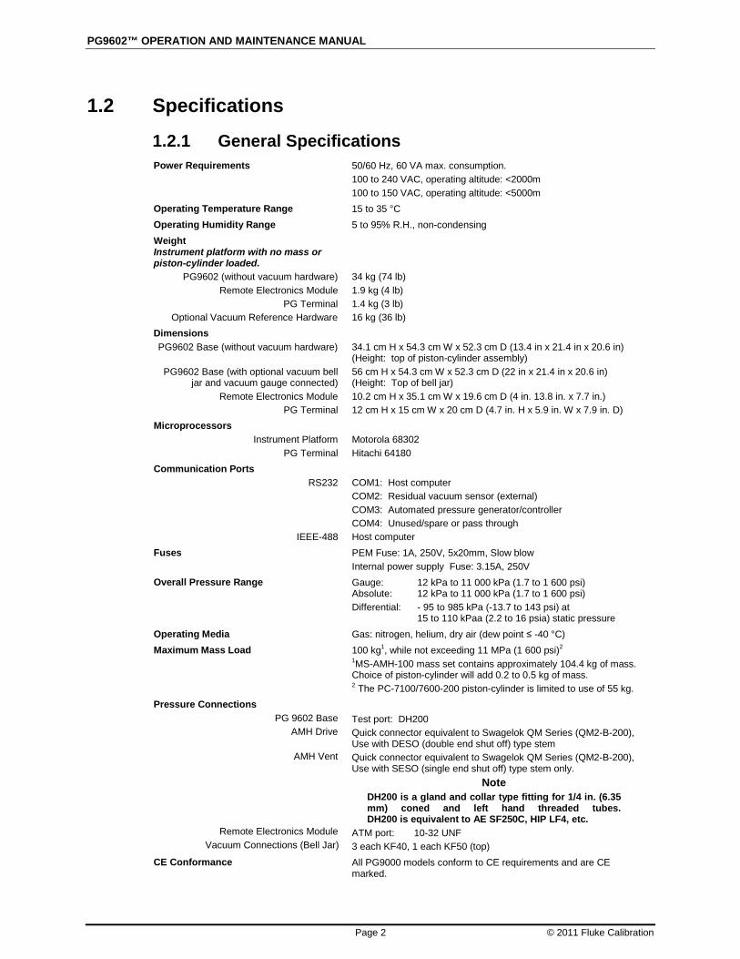
1.2.1 General Specifications Power Requirements 50/60 Hz, 60 VA max. consumption.
100 to 240 VAC, operating altitude: <2000m 100 to 150 VAC, operating altitude: <5000m
Operating Temperature Range 15 to 35 °C Operating Humidity Range 5 to 95% R.H., non-condensing Weight Instrument platform with no mass or piston-cylinder loaded.
PG9602 (without vacuum hardware) Remote Electronics Module
PG Terminal Optional Vacuum Reference Hardware
34 kg (74 lb) 1.9 kg (4 lb) 1.4 kg (3 lb) 16 kg (36 lb)
Dimensions PG9602 Base (without vacuum hardware)
PG9602 Base (with optional vacuum bell
jar and vacuum gauge connected) Remote Electronics Module
PG Terminal
34.1 cm H x 54.3 cm W x 52.3 cm D (13.4 in x 21.4 in x 20.6 in) (Height: top of piston-cylinder assembly) 56 cm H x 54.3 cm W x 52.3 cm D (22 in x 21.4 in x 20.6 in) (Height: Top of bell jar) 10.2 cm H x 35.1 cm W x 19.6 cm D (4 in. 13.8 in. x 7.7 in.) 12 cm H x 15 cm W x 20 cm D (4.7 in. H x 5.9 in. W x 7.9 in. D)
Microprocessors Instrument Platform
PG Terminal
Motorola 68302 Hitachi 64180
Communication Ports RS232
IEEE-488
COM1: Host computer COM2: Residual vacuum sensor (external) COM3: Automated pressure generator/controller COM4: Unused/spare or pass through Host computer
Fuses PEM Fuse: 1A, 250V, 5x20mm, Slow blow Internal power supply Fuse: 3.15A, 250V
Overall Pressure Range Gauge: 12 kPa to 11 000 kPa (1.7 to 1 600 psi) Absolute: 12 kPa to 11 000 kPa (1.7 to 1 600 psi) Differential: - 95 to 985 kPa (-13.7 to 143 psi) at 15 to 110 kPaa (2.2 to 16 psia) static pressure
Operating Media Gas: nitrogen, helium, dry air (dew point ≤ -40 °C) Maximum Mass Load 100 kg1, while not exceeding 11 MPa (1 600 psi)2
1MS-AMH-100 mass set contains approximately 104.4 kg of mass. Choice of piston-cylinder will add 0.2 to 0.5 kg of mass. 2 The PC-7100/7600-200 piston-cylinder is limited to use of 55 kg.
Pressure Connections PG 9602 Base
AMH Drive
AMH Vent
Remote Electronics Module Vacuum Connections (Bell Jar)
Test port: DH200 Quick connector equivalent to Swagelok QM Series (QM2-B-200), Use with DESO (double end shut off) type stem Quick connector equivalent to Swagelok QM Series (QM2-B-200), Use with SESO (single end shut off) type stem only.
Note DH200 is a gland and collar type fitting for 1/4 in. (6.35 mm) coned and left hand threaded tubes. DH200 is equivalent to AE SF250C, HIP LF4, etc.
ATM port: 10-32 UNF 3 each KF40, 1 each KF50 (top)
CE Conformance All PG9000 models conform to CE requirements and are CE marked.

1. INTRODUCTION
Page 3 © 2011 Fluke Calibration
1.2.1.1 AMH Automated Mass Handler (Optional) Power Requirements:
Operating Temperature: Dimensions:
15 VDC @ 2 A, 30 W max. consumption 15 to 35 ºC 41 cm H x 41 cm W x 36 cm D (16.3 in. x 16.1 in. x 14.1 in.)
Weight: Power/Communications:
12 kg (25 lbs) Custom 8 pin connector
AMH Drive Air Supply: 550 kPa (80 psi), ± 10%, minimal flow AMH Vacuum Supply: At least 50 kPa (7.5 pi) under atmosphere, minimal flow
Pressure Connections: Pressure: Vacuum:
Quick connector DESO (double end shut off) type stem Quick connector SESO (single end shut off) type stem
CE conformance: Available, must be specified
1.2.1.2 Embedded Features • Local control with 2 x 20 vacuum fluorescent display and 4 x 4 function
driven keypad. • Real time display and measurement of ambient (pressure, temperature,
humidity) and instrument (piston-cylinder temperature, piston position, piston drop rate, piston rotation rate, piston rotation decay rate, reference vacuum) conditions.
• Real time mass-to-pressure and pressure-to-mass calculations taking into consideration all environmental and operational variables.
• Full gas and liquid fluid head corrections including DUT head correction and piston position head correction. Barometer head correction included for atmosphere reference operation (gauge mode).
• Adjustable mass loading resolution (0.01 g to 0.1 kg). • Audible prompts of instrument status (piston movement, Ready/Not Ready
indication) with override capability. • Integrated automated mass handling option (AMH-100-VAC). • Interfacing and automatic exploitation of external barometer via RS232. • Interfacing and automatic exploitation of any external vacuum gauge via
RS232. • Semi-automated differential mode to define low differential pressures at
various static pressures between vacuum and two atmospheres. • Storage and one step activation of metrological data on up to 17 piston-
cylinder modules, (3) mass sets and (3) mass loading bells. • Continuous pressure Ready/Not Ready indication based on measured
conditions. • Motorized, intelligent piston drive system based measured rotation rate with
operator alert and manual override. • Integrated automated pressure control with standard Fluke Calibration
pressure controllers. • Full RS232 and IEEE-488 communications with multi-level commands to set
and read all instrument functions.
PG9602™ OPERATION AND MAINTENANCE MANUAL
© 2011 Fluke Calibration Page 4
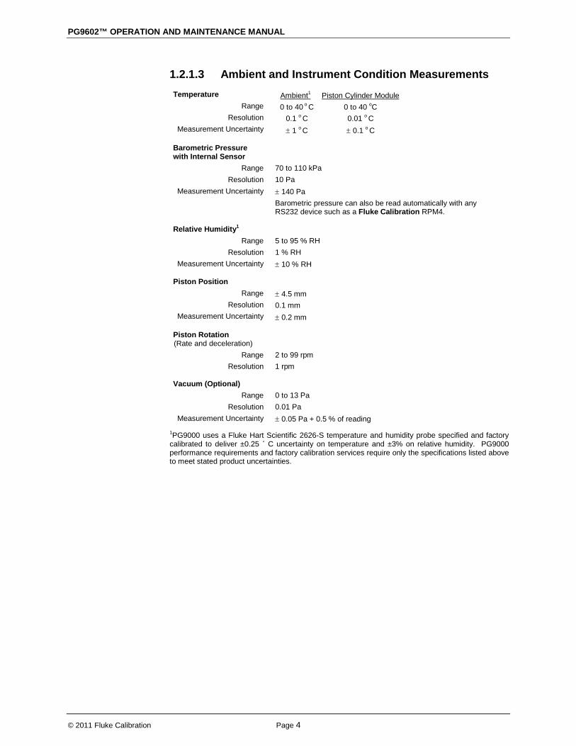
1.2.1.3 Ambient and Instrument Condition Measurements Temperature
Range Resolution
Measurement Uncertainty
Ambient1 0 to 40 o C 0 to 40 oC
Piston Cylinder Module
0.1 o C 0.01 o C ± 1 o C ± 0.1 o C
Barometric Pressure with Internal Sensor
Range Resolution
Measurement Uncertainty
70 to 110 kPa 10 Pa ± 140 Pa Barometric pressure can also be read automatically with any RS232 device such as a Fluke Calibration RPM4.
Relative Humidity1
Range Resolution
Measurement Uncertainty
5 to 95 % RH 1 % RH ± 10 % RH
Piston Position Range
Resolution Measurement Uncertainty
± 4.5 mm 0.1 mm ± 0.2 mm
Piston Rotation (Rate and deceleration)
Range Resolution
2 to 99 rpm 1 rpm
Vacuum (Optional) Range
Resolution Measurement Uncertainty
0 to 13 Pa 0.01 Pa ± 0.05 Pa + 0.5 % of reading
1PG9000 uses a Fluke Hart Scientific 2626-S temperature and humidity probe specified and factory calibrated to deliver ±0.25 ˚ C uncertainty on temperature and ±3% on relative humidity. PG9000 performance requirements and factory calibration services require only the specifications listed above to meet stated product uncertainties.

1. INTRODUCTION
Page 5 © 2011 Fluke Calibration
1.2.2 Piston-Cylinder Modules All piston-cylinders are complete integrated metrological assemblies that include mounting hardware, upper and lower travel stops, spring preloading system, and are delivered in individual shipping and storage “bullet” cases. Gas operated, gas lubricated piston-cylinders (PC-7100/7600) used with PG7000 are compatible with PG9602.
Note A piston-cylinder delivered with a PG7102 or PG7601 is compatible with PG9602; however its metrological properties must be recertified for operation to determine uncertainty at higher mass loads. Existing PC-7100/7600-200 (200 kPa/kg) piston-cylinders are supported only up to the mass set for which they were originally certified (35 kg or 55 kg if it was delivered with a PG7102).
PC-7100/7600-10, TC PC-7100/7600-10-L
Operation Piston Material
Cylinder Material Nominal Diameter
Nominal Area Mounting System
Gas operated, gas lubricated Tungsten carbide Tungsten carbide 35 mm 1 000 mm2 Simple free deformation
PC-7100/7600-20 Operation
Piston Material Cylinder Material
Nominal Diameter Nominal Area
Mounting System
Gas operated, gas lubricated Tungsten carbide Tungsten carbide 25 mm 500 mm2 Simple free deformation
PC-7100/7600-50 Operation
Piston Material Cylinder Material
Nominal Diameter Nominal Area
Mounting system
Gas operated, gas lubricated Tungsten carbide Tungsten carbide 16 mm 200 mm2 Negative free deformation
PC-7100/7600-100 Operation
Piston Material Cylinder Material
Nominal Diameter Nominal Area
Mounting System
Gas operated, gas lubricated Tungsten carbide Tungsten carbide 11 mm 98 mm2 Negative free deformation

PG9602™ OPERATION AND MAINTENANCE MANUAL
© 2011 Fluke Calibration Page 6
1.2.3 Mass Sets Note
A mass set delivered with a PG7000 is compatible with PG9602, however be sure to be aware of potential differences between the nominal makeup mass value and the nominal Piston mass + Mass Bell mass (i.e. using a 4.5 kg MKUP mass with a 1 kg piston+bell).
All masses are delivered in molded, reusable, transit cases with custom inserts.
Masses > 50g Material
Finish Adjustment Tolerance
Uncertainty of Measured Values
304L non-magnetic stainless steel Electro polished ± 20 ppm of nominal value (manual AND AMH mass sets do not have fixed adjustment tolerances) ± 5 ppm or 1 mg, whichever is greater
Masses < 50g ± 1 mg
1.2.4 Pressure Measurements Note
For uncertainty in piston-cylinder effective area and typical measurement uncertainty in pressure defined by the piston gauge, see the piston-cylinder calibration report and current revision of Fluke Calibration Technical Note 0180TN12, “Typical Pressure Measurement Uncertainty for a PG9607 and PG9602 Piston Gauge”.
PC-7100/7600-10 PC-7100/7600-10-L
Sensitivity1 Reproducibility2
Typical Drop Rate (35 kg)
0.02 Pa + 0.5 ppm ± 2 ppm 0.2 mm/min
PC-7100/7600-20 Sensitivity1
Reproducibility2
Typical Drop Rate (35 kg)
0.04 Pa + 0.5 ppm ± 2 ppm 0.3 mm/min
PC-7100/7600-50 Sensitivity1
Reproducibility2 Typical Drop Rate (35 kg)
0.1 Pa + 0.5 ppm ± 2 ppm 0.5 mm/min
PC-7100/7600-100 Sensitivity1
Reproducibility2 Typical Drop Rate (35 kg)
0.2 Pa + 0.5 ppm ± 3 ppm 0.7 mm/min
1 Sensitivity: The smallest variation in input detectable in output. 2 Reproducibility: The root sum square of the stability of effective area and stability of the
AMH-100 mass set for 1 year. Refer to Fluke Calibration Technical Note 0180TN12.
1. INTRODUCTION
Page 7 © 2011 Fluke Calibration
1.3 Front and Rear Panels
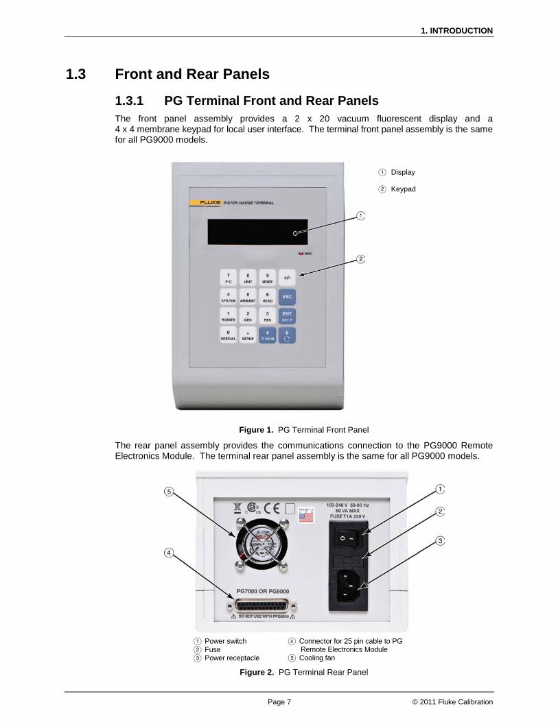
1.3.1 PG Terminal Front and Rear Panels The front panel assembly provides a 2 x 20 vacuum fluorescent display and a 4 x 4 membrane keypad for local user interface. The terminal front panel assembly is the same for all PG9000 models.
Display Keypad
Figure 1. PG Terminal Front Panel
The rear panel assembly provides the communications connection to the PG9000 Remote Electronics Module. The terminal rear panel assembly is the same for all PG9000 models.
Power switch Fuse Power receptacle
Connector for 25 pin cable to PG Remote Electronics Module
Cooling fan
Figure 2. PG Terminal Rear Panel
PG9602™ OPERATION AND MAINTENANCE MANUAL
© 2011 Fluke Calibration Page 8
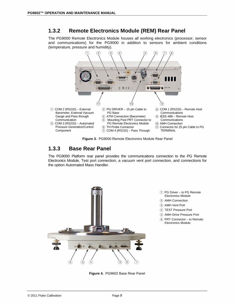
1.3.2 Remote Electronics Module (REM) Rear Panel The PG9000 Remote Electronics Module houses all working electronics (processor, sensor and communications) for the PG9000 in addition to sensors for ambient conditions (temperature, pressure and humidity).
COM 2 (RS232) – External
Barometer, External Vacuum Gauge and Pass through Communication
COM 3 (RS232) – Automated Pressure Generation/Control Component
PG DRIVER – 15 pin Cable to PG Base
ATM Connection (Barometer) Mounting Post PRT Connector to
PG Remote Electronics Module TH Probe Connector COM 4 (RS232) – Pass Through
COM 1 (RS232) – Remote Host Communications
IEEE-488 – Remote Host Communications
AMH Connection Connector for 25 pin Cable to PG
TERMINAL
Figure 3. PG9000 Remote Electronics Module Rear Panel
1.3.3 Base Rear Panel The PG9000 Platform rear panel provides the communications connection to the PG Remote Electronics Module, Test port connection, a vacuum vent port connection, and connections for the option Automated Mass Handler.
PG Driver – to PG Remote Electronics Module
AMH Connection AMH Vent Port TEST Pressure Port AMH Drive Pressure Port PRT Connector – to Remote
Electronics Module
Figure 4. PG9602 Base Rear Panel

Page 9 © 2011 Fluke Calibration
2. Installation
2.1 Unpacking and Inspection
2.1.1 Removing From Packaging A typical PG9000 system includes the PG9000 Platform (see Section 2.1.1.1), a mass set (see Section 2.1.1.6), at least one piston-cylinder assembly (see Section 2.1.1.2) and other accessories such as vacuum reference hardware (see Section 2.1.1.3), an automated mass handler (see Section 2.1.1.4) and/or pressure generation and control components (see the accessory Operation and Maintenance Manual or instruction sheet).
2.1.1.1 Platform The PG9000 Platform consists of the PG9000 Base, Remote Electronics Module, Terminal and interconnect accessories. The Base is shipped in a custom wooden crate. The Platform components are shipped in a reusable, molded shipping and storage case. The cables and accessories are shipped in a corrugated container with other PG9000 accessories including operating instructions and calibration reports. Open the PG9000 Base shipping crate (71 cm x 71 cm x 56 cm). Carefully lift the PG9000 Base from its position in the lower packing insert.
Note the orientation so that the same orientation will be used when PG9000 is repacked.
Warning The PG9000 Base has a mass of 34 kg (74 lb). It is recommended to remove it from the packaging with two people on opposite sides of the shipping container. Removing or lifting with only one person may lead to injury.
Open the PG9000 components molded, reusable recalibration transit case and the accessories corrugated shipping container.
Remove the PG Terminal, Remote Electronics Module and Temperature-Humidity Probe from the recalibration transit case and the Platform accessories from the shipping container. Inspect and inventory the accessories (see Section 2.1.2.1).
Reinstall the packing inserts into the shipping and storage cases and store in a safe place.

PG9602™ OPERATION AND MAINTENANCE MANUAL
© 2011 Fluke Calibration Page 10
2.1.1.2 Piston-Cylinder Assemblies The piston-cylinder modules are shipped in Acetal bullet cases that are packed in corrugated containers with custom foam inserts. Open the corrugated containers and remove the piston-cylinder modules and accessories. The bullet cases screw open by turning the lid counterclockwise.
2.1.1.3 Vacuum Reference Hardware (optional) The optional PG9000 Vacuum Reference Hardware includes the vacuum Bell Jar, reference vacuum sensor with power supply and interconnect cables and fittings necessary for vacuum operation. The PG9000 Bell Jar is packed in a large wooden crate (66 cm x 66cm x 71 cm). The vacuum reference sensor, power supply and associated fittings and cables are packed in a reusable molded Vacuum Measurement Kit transit case. Remaining fittings and adaptors are shipped in the PG9000 accessories corrugated container (see Section 2.1.2.3).
2.1.1.4 AMH-100, Automated Mass Handler (optional) AMH-100-VAC is delivered in a corrugated container with foam cut outs to hold the AMH in place. Accessories are bagged together and packaged in a separate corrugated container with other PG9000 system accessories. Remove all parts from the shipping boxes. See Section 2.1.2.4 for more detail.
2.1.1.5 AMH Mass Set (optional) PG9000 AMH masses are shipped in reusable, molded shipping and storage cases. One of the cases contains the binary masses, binary mass carrier, mass bell and lifting shaft/trim mass tray. The other cases contain the main masses of 10 kg (see Section 2.1.2.2 for mass set content detail). Each mass is packed in a plastic bag and then placed in a protective shipping insert. The PG9000 AMH masses should be removed from their shipping cases and inventoried when setting up the PG9000 system (see Section 2.1.1.6 for mass set content detail).
Caution The stability over time of PG9000 pressure measurements is a function of the stability of the masses loaded on the cylinder. Precautions should be taken in handling the masses to minimize influences that may change their mass. This includes always wearing protective gloves when handling the masses to avoid contaminating them with body oils and perspiration. Protective gloves are provided in the accessory kits of PG9000 Platforms.
2.1.1.6 Manual Mass Set The PG9000 manual masses are shipped in reusable, molded shipping and storage cases. The PG9000 masses should be removed from their shipping cases and inventoried when setting up the PG9000 system (see Section 2.1.2.2 for mass set content detail). The default manual mass set is the type MS-7002 which has a 4 kg makeup mass.
2. INSTALLATION
Page 11 © 2011 Fluke Calibration
Caution • The mass loading bell is a metrological element that is part
of the mass set. Like all of the masses, it is preferable not to handle it with bare hands. Protective gloves are provided in the accessory kit of each PG9000 Platform.
• The stability over time of PG9000 pressure measurements is a function of the stability of the masses loaded on the piston. Precautions should be taken in handling the masses to minimize influences that may change their mass. This includes always wearing protective gloves when handling the masses to avoid contaminating them with body oils and perspiration. Protective gloves are provided in the accessory kits of PG9000 Platforms.
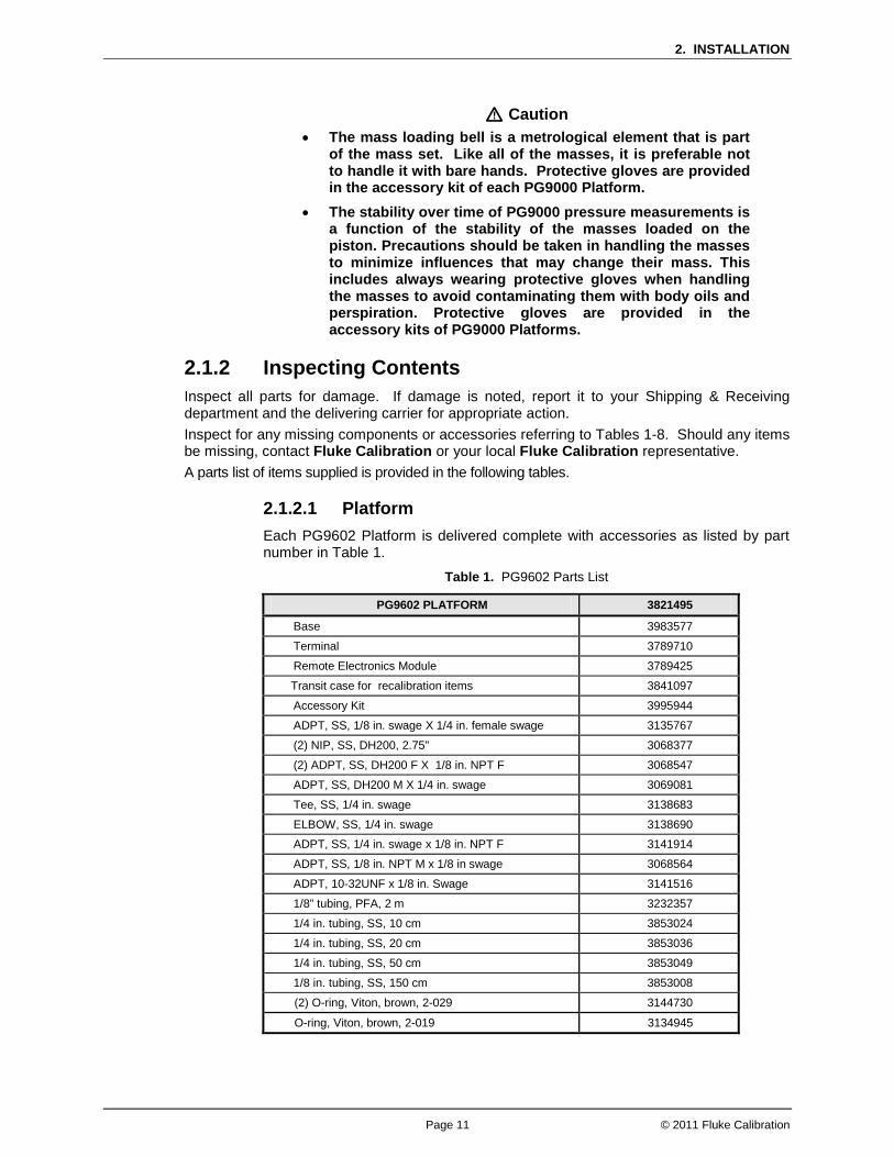
2.1.2 Inspecting Contents Inspect all parts for damage. If damage is noted, report it to your Shipping & Receiving department and the delivering carrier for appropriate action. Inspect for any missing components or accessories referring to Tables 1-8. Should any items be missing, contact Fluke Calibration or your local Fluke Calibration representative. A parts list of items supplied is provided in the following tables.
2.1.2.1 Platform Each PG9602 Platform is delivered complete with accessories as listed by part number in Table 1.
Table 1. PG9602 Parts List
PG9602 PLATFORM 3821495
Base 3983577
Terminal 3789710
Remote Electronics Module 3789425
Transit case for recalibration items 3841097
Accessory Kit 3995944
ADPT, SS, 1/8 in. swage X 1/4 in. female swage 3135767
(2) NIP, SS, DH200, 2.75" 3068377
(2) ADPT, SS, DH200 F X 1/8 in. NPT F 3068547
ADPT, SS, DH200 M X 1/4 in. swage 3069081
Tee, SS, 1/4 in. swage 3138683
ELBOW, SS, 1/4 in. swage 3138690
ADPT, SS, 1/4 in. swage x 1/8 in. NPT F 3141914
ADPT, SS, 1/8 in. NPT M x 1/8 in swage 3068564
ADPT, 10-32UNF x 1/8 in. Swage 3141516
1/8” tubing, PFA, 2 m 3232357
1/4 in. tubing, SS, 10 cm 3853024
1/4 in. tubing, SS, 20 cm 3853036
1/4 in. tubing, SS, 50 cm 3853049
1/8 in. tubing, SS, 150 cm 3853008
(2) O-ring, Viton, brown, 2-029 3144730
O-ring, Viton, brown, 2-019 3134945

PG9602™ OPERATION AND MAINTENANCE MANUAL
© 2011 Fluke Calibration Page 12
2.1.2.2 Piston-cylinder Modules Table 2. Piston-Cylinder Modules Parts List
10 kPa
PC-7100/ 7600-10-L
10 kPa PC-7100/
7600-10 TC
20 kPa PC-7100/ 7600-20
50 kPa PC-7100/ 7600-50
100 kPa PC-7100/ 7600-100
Piston-Cylinder Kit 3171975 3070095 3071581 3070109 3071615
Piston-Cylinder Module 3125106 3122937 3122116 3124088 3122234
Hermetic Acetal Bullet Case 3070203 3070203 3070203 3070203 3070203
Accessory Kit 3125242 3122928 3122229 3124345 3124345
O-rings 3134867 3136458
3134867 3136458
3134867 3136458
3134880 3136458
3134880 3136458
Insertion Tool 3071793 3071841 N/A N/A N/A
Calibration Report 3152121 3152121 3152121 3152121 3152121
(2) O-ring, Buna, 2-242 3135041
Allen wrench, 2.5 mm 3136044
Allen wrench, 3 mm 3135703
Allen wrench, 5 mm 3136098
Krytox GPL205/6 0.5 oz 2493420
Gift kit with gloves 3123777
Terminal to Platform Cable (DB25M – DB25F) 3068724
PRT Cable, PG Platform 3778220
TH Probe Cable 3837033
Driver Cable, PG Platform 3068683
Power Cable – US 3133781
Power Cable – UK 3153005
Documentation Calibration Report (PG) Technical Data Manual Documentation CD
3152121 3152139 3995967 3139043
2. INSTALLATION
Page 13 © 2011 Fluke Calibration
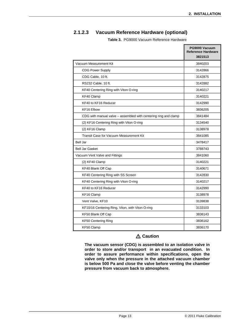
2.1.2.3 Vacuum Reference Hardware (optional) Table 3. PG9000 Vacuum Reference Hardware
PG9000 Vacuum Reference Hardware
3821513
Vacuum Measurement Kit 3840203
CDG Power Supply 3142866
CDG Cable, 10 ft. 3142875
RS232 Cable, 10 ft. 3142882
KF40 Centering Ring with Viton O-ring 3140217
KF40 Clamp 3140221
KF40 to KF16 Reducer 3142990
KF16 Elbow 3836205
CDG with manual valve – assembled with centering ring and clamp 3841484
(2) KF16 Centering Ring with Viton O-ring 3134540
(2) KF16 Clamp 3138978
Transit Case for Vacuum Measurement Kit 3841085
Bell Jar 3478417
Bell Jar Gasket 3788743
Vacuum Vent Valve and Fittings 3841060
(2) KF40 Clamp 3140221
KF40 Blank Off Cap 3140671
KF40 Centering Ring with SS Screen 3142830
KF40 Centering Ring with Viton O-ring 3140217
KF40 to KF16 Reducer 3142990
KF16 Clamp 3138978
Vent Valve, KF10 3139838
KF10/16 Centering Ring, Viton, with Viton O-ring 3133103
KF50 Blank Off Cap 3836143
KF50 Centering Ring 3836162
KF50 Clamp 3836170
Caution
The vacuum sensor (CDG) is assembled to an isolation valve in order to store and/or transport in an evacuated condition. In order to assure performance within specifications, open the valve only when the pressure in the attached vacuum chamber is below 500 Pa and close the valve before venting the chamber pressure from vacuum back to atmosphere.

PG9602™ OPERATION AND MAINTENANCE MANUAL
© 2011 Fluke Calibration Page 14
2.1.2.4 AMH-100, Automated Mass Handler (optional) Table 4. AHM-100-VAC Parts List
DESCRIPTION PART #
1 ea. AHM-100-VAC Automated Mass Handler 3821508
Accessory kit including: 3841402
1 ea. Power/Comm Cable 3843744
2 m 1/8 in. PFA tubing 3232357
2 m 1/4 in. PFA tubing 3232378
2 m 3/8 in. PFA tubing 3232445
1 ea. 3/8 in. Tee 3843090
1 ea. Reducer, 1/4 in. Swage x 3/8 in. Swage 3843104
1 ea. 3/8 in. Port Connector 3843119
1 ea. ADPT, 1/8 in. Swage x 1/4 in. NPTM 3135780
1 ea. Quick Connector Stem, 1/8 in. Swage DESO (red band) 3123691
1 ea. Quick Connector Assy, with valve, AMH VAC Port (blue band) 3121719
4 ea. Cable Tie, Hook and Loop 2008964
1 ea. 3 mm Hex Wrench 3141776
2.1.2.5 Mass Sets PG9000 mass sets are composed of different combinations of individual masses and accessories depending on the specific mass set ordered (see Tables 2 - 5). If an AHM-100 is not used then a Manual Mass Set is required.
Table 5. Manual Mass Set Parts List (excluding 80 and 100 kg)
DESCRIPTION PART NO.
Mass Set Refer to Table 8
Reusable Molded Transit Case with Foam Inserts 35 kg set 40 kg set 45 kg set 55 kg set
3068969 1 ea. 1 ea. 1 ea. 1 ea.
3068991 1 ea. 1 ea. 1 ea. 2 ea.
Mass Set Storage Tray and Spindle 3147461 and 3148764
Dust Covers 3138017 and 3138130
Calibration Report 3152121
Table 6. Manual Mass Set Parts List (80 and 100 kg)
DESCRIPTION PART NO.
Mass Set Refer to Table 8
Reusable Molded Transit Case with Foam Inserts 80 kg set 100 kg set
3068969 1 ea. 1 ea.
3068984 2 ea. 3 ea.
Mass Set Storage Tray and Spindle 3147461 and 3148764
Dust Covers 3138017 and 3138127
Calibration Report 3152121

2. INSTALLATION
Page 15 © 2011 Fluke Calibration
Table 7. AMH-100 Mass Set Parts List
DESCRIPTION PART NO.
Mass Set Refer to Table 8
Reusable Molded Transit Case with Foam Inserts 40 kg set (MS-AMH-40) 60 kg set (MS-AMH-60) 80 kg set (MS-AMH-80) 100 kg set (MS-AMH-100)
3123990 1 ea. 1 ea. 1 ea. 1 ea.
3068984 1 ea. 2 ea. 2 ea. 3 ea.
Calibration Report 3152121
Table 8. Mass Set Compositions
DESIGNATION PART # NOMINAL
TOTAL MASS (kg)
MASS SET COMPOSITION
10 kg
5 kg
2 kg
1 kg
0.5 kg
0.2 kg
0.1 kg
MAKE-UP MASS (kg)
MS-7002-35 3069861 35 - 5 2 1 1 2 1 1 (4) -
MS-7002-40 3070021 40 - 6 2 1 1 2 1 1 (4) -
MS-7002-45 3069980 45 - 7 2 1 1 2 1 1 (4) -
MS-7002-55 3069877 55 - 9 2 1 1 2 1 1 (4) -
MS-7002-80 3070000 80 6 1 2 1 1 2 1 1 (9) -
MS-7002-100 3070017 100 8 1 2 1 1 2 1 1 (9) -
DESIGNATION PART # NOMINAL TOTAL
MASS (kg)
MASS SET COMPOSITION
10 kg
6.4 kg
6.2 kg
3.2 kg
1.6 kg
0.8 kg
0.4 kg
0.2 kg
0.1 kg
BELL, SHAFT, BINARY MASS
CARRIER (3 PARTS)
MS-AMH-40 3071528 40 3 1 - 1 1 1 1 1 1 1
MS-AMH-60 3071519 60 5 1 - 1 1 1 1 1 1 1
MS-AMH-80 3071504 80 7 1 - 1 1 1 1 1 1 1
MS-AMH-100 3071440 100 9 1 - 1 1 1 1 1 1 1
All mass sets include a trim mass set of 50 g to 0.01 g (total 100 g)
Note The mass loading bell and piston make up part of the total mass load. The mass loading bell for loading manual mass sets is ordered and shipped separately. The mass loading bell for AMH mass sets is delivered with the mass set.
2.2 Site Requirements The exact PG9000 system installation is affected by the elements other than the PG9000 Platform that make up the PG9000 system.
When selecting and preparing a site to set up the PG9000 system, the following should be considered:
• Ambient conditions: To achieve optimum metrological performance, ambient conditions should be controlled and maintained within the following: ♦ Temperature: 19 to 26 °C, minimize rate of change of temperature. ♦ Relative Humidity: 5 to 95 %RH (non-condensing). ♦ Ambient Pressure: Minimize external influences that will cause barometric instability.

PG9602™ OPERATION AND MAINTENANCE MANUAL
© 2011 Fluke Calibration Page 16
♦ Air Currents: Do not install the PG9000 Platform under a source of vertical air currents such as an overhead air conditioning duct. These can blow on the mass load and add unquantified forces.
♦ Vibration: Minimize local vibration. Excessive vibration will reduce the stability of the pressures defined by PG9000 (vibration affects the floating piston). Excessive high frequency vibration, for example from a vacuum pump on the same table as the PG9000, may affect piston sensitivity.
• Bench stability: Up to 100 kg may be loaded and unloaded onto the PG9000 Platform. The bench on which the PG9000 sits should not deflect significantly under the mass load changes. This can be verified by setting the PG9000 Platform on the bench, leveling it, loading and unloading the complete mass set while observing whether the level setting changes.
• Location of other components: Plan the space required and a convenient layout for the complete PG9000 system including the PG Terminal, Remote Electronics Module, mass set, pressure generation/control component(s), test instrument connection and computer (if present). If using a PPC or MPC to generate/control pressure, see its Operation and Maintenance Manual for information on installing it. If a Fluke Calibration interconnections kit is being used to interconnect the components, see its instruction sheet.
• Electrical and pressure supplies: Plan the supply of electrical power to the PG Terminal and to the pressure generation/control component(s), if needed. If using a PPC or MPC to generate/control pressure, see its Operation and Maintenance Manual for information on the pressures source(s) it needs and how to connect them. Gas supplied to the piston-cylinder module(s) must be clean and dry (instrument grade minimum, high purity preferred) to avoid contaminating the piston-cylinder gap.
• Reference vacuum supply: Plan for the vacuum connection to the bell jar and the AMH, and the location of the reference vacuum pump.
• Bell jar (optional) placement: Plan a location for the bell jar when it is removed from the platform to load and unload masses.
• AMH automated mass handler (optional): o Location
o
: If an AMH is being used, consider that the AMH mass handler will occasionally be removed from the PG9000 Platform. A convenient place to put it when it is removed should be planned. Drive air supply
3.7.1: The drive air supply provides power to operate the mass lifter and the
binary mass selector pins (see Section ). Drive air requirements:
• Flow rate: Very low, avoid restrictions or excessive length of connecting tubing
• Cleanliness: If air from a compressor is used it should be filtered and dried, preferably with a filter regulator with a coalescing filter. The recommendation is for a 5-micron filter upstream of a 0.01-micron coalescing filter. The main concern is the elimination of humidity, which could corrode the AMH pneumatic controls.
• Drive air pressure requirements are different for different mass set sizes. See Table 9:
Table 9. Drive Air Pressure Requirement by Mass Set
MASS SET DRIVE AIR [kPa (psi)]
MS-AMH-40
275 (40)
MS-AMH-60
380 (55)
MS-AMH-80
450 (65)
MS-AMH-100 550 (80)

2. INSTALLATION
Page 17 © 2011 Fluke Calibration
Caution Do not operate the AMH with drive pressure lower than 275 kPa (40 psi). Damage to the AMH could result.
o Vacuum supply
The vacuum pump for the pressure controller of the PG9000 system can be used for the AMH vacuum supply
: The vacuum supply is necessary for AMH operation when there is vacuum in the vacuum chamber (absolute by vacuum mode PG9000 operation). The vacuum supply assures that the binary mass selection pins remain in the correct position and evacuates internal AMH volumes to minimize the likelihood of leaks into the reference vacuum.
Vacuum drive requirements: Flow rate: Very low, avoid restrictions or excessive length of connecting tubing Vacuum pressure: At least 50 kPa (7.5 psi) under atmosphere
Caution When using a PG9000 in “absolute by vacuum” mode, do not operate the AMH without having a vacuum supply connected to the AMH Vent. Always check that the AMH is supplied with vacuum BEFORE establishing reference vacuum in the AMH bell jar. Failure to do so may result in damage to the binary mass pins and/or binary masses.
Caution Do not plug the AMH vent connection. Use only a “SESO” type quick-connector stem. Plugging the AMH vent connection will prevent the mass pins from retracting, leading to serious damage to the AMH internal components.
2.3 Setup
2.3.1 Preparing for Operation Note
Before setting up the PG9000 system, see Section 2.2 for information on site requirements.
To prepare PG9000 for operation: Set up the PG9000 Platform (see Section 2.3.1.1). Make the system pressure interconnections (see Section 2.3.1.2). If a manual mass set is being used, set up the manual mass set (see Section 2.3.1.3). If an optional AMH is being used, set it up with its mass set (see Sections 2.3.1.5 and
2.3.1.4). If the PG9000 is to be used with a vacuum reference, set up the optional vacuum
reference hardware (see Section 2.3.1.5).
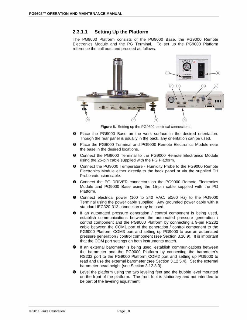
PG9602™ OPERATION AND MAINTENANCE MANUAL
© 2011 Fluke Calibration Page 18
2.3.1.1 Setting Up the Platform The PG9000 Platform consists of the PG9000 Base, the PG9000 Remote Electronics Module and the PG Terminal. To set up the PG9000 Platform reference the call outs and proceed as follows:
Figure 5. Setting up the PG9602 electrical connections
Place the PG9000 Base on the work surface in the desired orientation. Though the rear panel is usually in the back, any orientation can be used.
Place the PG9000 Terminal and PG9000 Remote Electronics Module near the base in the desired locations.
Connect the PG9000 Terminal to the PG9000 Remote Electronics Module using the 25-pin cable supplied with the PG Platform.
Connect the PG9000 Temperature - Humidity Probe to the PG9000 Remote Electronics Module either directly to the back panel or via the supplied TH Probe extension cable.
Connect the PG DRIVER connectors on the PG9000 Remote Electronics Module and PG9000 Base using the 15-pin cable supplied with the PG Platform.
Connect electrical power (100 to 240 VAC, 50/60 Hz) to the PG9000 Terminal using the power cable supplied. Any grounded power cable with a standard IEC320-313 connection may be used.
If an automated pressure generation / control component is being used, establish communications between the automated pressure generation / control component and the PG9000 Platform by connecting a 9-pin RS232 cable between the COM1 port of the generation / control component to the PG9000 Platform COM3 port and setting up PG9000 to use an automated pressure generation / control component (see Section 3.10.9). It is important that the COM port settings on both instruments match.
If an external barometer is being used, establish communications between the barometer and the PG9000 Platform by connecting the barometer’s RS232 port to the PG9000 Platform COM2 port and setting up PG9000 to read and use the external barometer (see Section 3.12.5.4). Set the external barometer head height (see Section 3.12.3.3).
Level the platform using the two leveling feet and the bubble level mounted on the front of the platform. The front foot is stationary and not intended to be part of the leveling adjustment.

2. INSTALLATION
Page 19 © 2011 Fluke Calibration
2.3.1.2 System Pressure Interconnections Interconnect the PG9000 Platform, pressure generation / control components and a test connection. The pressure connection on the PG9000 TEST port is DH200 (DH200 is equivalent to Autoclave Engineers SF250C, and High Pressure Equipment Company (HIP) LF4). Adapters to convert the DH200 connection to 1/8 in. NPT female and 1/4 inch Swagelok® tube fitting are provided with PG9000 Platform accessories. Use the supplied fittings in the Accessory Kit (p/n 3995944) to build the PG9602 interconnections. See Table 1. PG9602 Parts List.
Figure 6. PG9602 Interconnections
The pressure connections for an optional Automatic Mass Handler are described in Section 2.3.1.5.
2.3.1.3 Setting up a Manual Mass Set Note
If installing a MS-AMH-100 mass set for use with an automated mass handling system, see Section 2.3.1.5.
To install a PG9000 manual mass set, place the mass loading tray (provided with the mass set accessories) at the desired location then install the individual masses on the mass loading tray. For convenience the main masses are stacked in reverse order to facilitate the proper mass loading protocol onto the PG9000. See Section 2.3.1.5 for instructions on installation of an AMH mass set for automated mass handling.
PG9000 masses are shipped in reusable, molded shipping and storage cases. One of the cases contains the masses of size 5 kg and under, the other cases contain the make up mass (4 or 9 kg depending on the mass set size), and main masses of 5 or 10 kg each. Each mass is packed in a plastic bag and then placed in a protective shipping insert.
Installing Masses on the Mass Loading Tray (Manual Mass Set)
Caution The stability over time of PG9000 pressure measurements is a function of the stability of the masses loaded on the piston. Precautions should be taken in handling the masses to minimize influences that may change their mass. This includes always wearing protective gloves when handling the masses to avoid contaminating them with body oils and perspiration. Protective gloves are provided in the accessory kits of PG9000 Platforms.
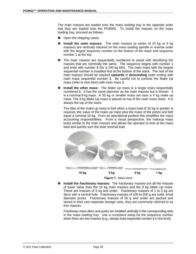
PG9602™ OPERATION AND MAINTENANCE MANUAL
© 2011 Fluke Calibration Page 20
The main masses are loaded onto the mass loading tray in the opposite order that they are loaded onto the PG9000. To install the masses on the mass loading tray, proceed as follows:
Open the shipping cases.
Install the main masses: The main masses (a series of 10 kg or 5 kg masses) are vertically stacked on the mass loading spindle in reverse order with the largest sequence number on the bottom of the stack and sequence number 1 at the top.
The main masses are sequentially numbered to assist with identifying the masses that are nominally the same. The sequence begins with number 1 and ends with number 8 (for a 100 kg MS). The main mass with the largest sequential number is installed first at the bottom of the stack. The rest of the main masses should be stacked upwards in descending order ending with main mass sequential number 1. Be careful not to confuse the Make Up mass (refer to next item) with main mass 1.
Install the other mass: The Make Up mass is a single mass sequentially numbered 1. It has the same diameter as the main masses but is thinner. It is a nominal 9 kg mass. A 55 kg or smaller mass set uses a 4 kg make up mass. The 9 kg Make Up mass is placed on top of the main mass stack. It is always the top of the stack.
The idea of the make up mass is that when a mass load of 10 kg or greater is required, the value of the make up mass plus the mass of the piston and bell equal a nominal 10 kg. From an operational position this simplifies the mass accounting responsibilities. From a visual perspective, the makeup mass looks similar to the main masses and allows the operator to look at the mass load and quickly sum the total nominal load.
Figure 7. Mass sizes
Install the fractionary masses: The fractionary masses are all the masses of lower value than the 10 kg main masses and the 9 kg Make Up mass. These are masses of 5 kg and under. Fractionary masses of 1 to 5 kg are discs with a central hole. Fractionary masses of 100 to 500 g are solid, small diameter pucks. Fractionary masses of 50 g and under are packed and stored in their own separate storage case, they are commonly referred to as trim masses.
Fractionary mass discs and pucks are installed vertically in the corresponding slots in the mass loading tray. Use a consistent setup for the sequence number when there are two masses (e.g., always load sequential number 1 in the front).
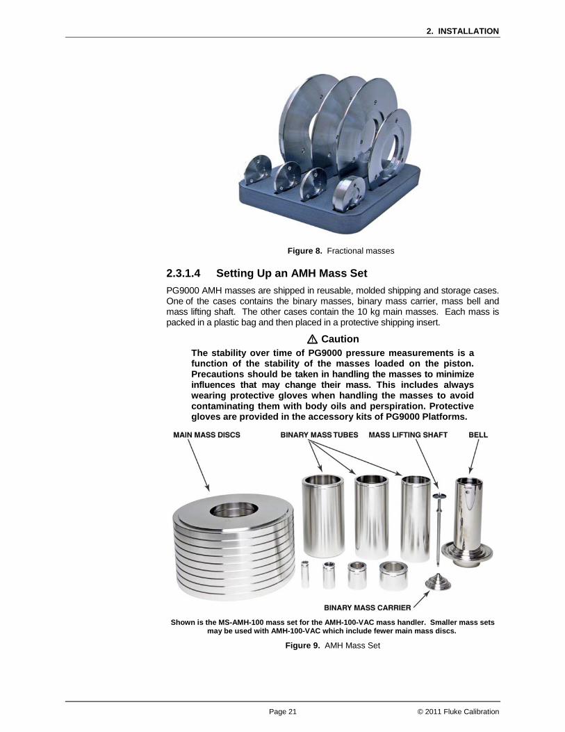
2. INSTALLATION
Page 21 © 2011 Fluke Calibration
Figure 8. Fractional masses
2.3.1.4 Setting Up an AMH Mass Set PG9000 AMH masses are shipped in reusable, molded shipping and storage cases. One of the cases contains the binary masses, binary mass carrier, mass bell and mass lifting shaft. The other cases contain the 10 kg main masses. Each mass is packed in a plastic bag and then placed in a protective shipping insert.
Caution The stability over time of PG9000 pressure measurements is a function of the stability of the masses loaded on the piston. Precautions should be taken in handling the masses to minimize influences that may change their mass. This includes always wearing protective gloves when handling the masses to avoid contaminating them with body oils and perspiration. Protective gloves are provided in the accessory kits of PG9000 Platforms.
Shown is the MS-AMH-100 mass set for the AMH-100-VAC mass handler. Smaller mass sets
may be used with AMH-100-VAC which include fewer main mass discs.
Figure 9. AMH Mass Set

PG9602™ OPERATION AND MAINTENANCE MANUAL
© 2011 Fluke Calibration Page 22
To install the AMH mass set, follow the order of operation:
Prepare the masses: Open the shipping cases and take inventory of the masses. Remove the mass elements from their plastic bags only when required to load them on the PG Base.
Install a piston-cylinder module in the PG9000 Platform: See Section 2.1.1.2.
Install the binary mass carrier: Place the pyramidal shaped carrier on top of the piston cap.
Install the mass loading bell: Slide the mass loading bell over the binary mass carrier and slide it down until the inside top of the bell sits on the binary mass carrier.
Install the main mass discs: Load the 10 kg main mass discs onto the mass bell starting with mass #1 and loading in sequential order. Mass #1 must be at the bottom of the stack and the highest sequenced number mass at the top. The mass sequence numbers are laser marked on the top surface of each mass.
Install the binary mass tubes: Load the binary mass tubes from the largest to smallest. The largest, long tubes slip down between the main mass stack and the bell. The smaller masses load onto the pyramidal steps of the binary mass carrier.
The mass loading process is mostly complete: The mass set is in the all loaded position, but do not yet install the mass lifting shaft assembly. It will be installed later after the AMH is installed over the masses on the platform (see Section 3.7.2.1).
Create the mass set and mass loading bell in the PG Terminal: If a mass set was ordered from the factory as part of a PG9000 system then the mass set data is preloaded into the PG9000 memory, and there is no need to create a mass set definition. See Sections 3.12.1.6 and 3.12.1.11 if a mass set definition must be created.
2.3.1.5 Setting Up An AMH Automated Mass Handler (optional)
The setup of the AMH can be broken down into 3 steps: Connect the drive air supply (see Section 2.3.1.5.1) Connect the drive vacuum supply (see Section 2.3.1.5.2) Connect the AMH communications (see Section 2.3.1.5.3)
2.3.1.5.1 Connecting AMH Drive The AMH accessories kit includes hardware to facilitate the connection of the drive air supply (see Table 4. AHM-100-VAC Parts List). Locate the drive air connection accessories including: • Quick-connector stem (DESO type with red band). • 2 meters pf 1/8 inch O.D., clear PFA tubing. • 1/8 inch Swagelok® tube connector x 1/4 inch NPT male adaptor.

2. INSTALLATION
Page 23 © 2011 Fluke Calibration
To use the supplied accessories to make the AMH drive air supply connection proceed as follows: Connect the quick-connector to one end of the PFA tube. Loosen the 1/8 in.
swage nut on the assembly slightly. Slip the PFA tube into the nut until it stops. Tighten the nut to swage the tube.
Connect the other end of the PFA tube to an appropriate drive air supply (see Section 2.2.2.1). If desired, use the 1/8 in. Swage x 1/4 in. NPT M adaptor.
Insert the quick-connector stem into the AMH DRIVE connection quick-connector, located on the rear of the PG9000 Base (color coded with red band). Press firmly until the stem clicks into place.
Apply drive air pressure to the connection and check for leaks.
Note The quick-connect stem seals when disconnected so the drive air supply may be applied before the quick-connect stem is inserted into the quick-connector.
Caution Do not operate the AMH with drive pressure lower than 275 kPa (40 psi). Damage to the AMH could result.
2.3.1.5.2 Connecting AMH Vent If operating the PG9000 in vacuum reference mode with AMH-100-VAC it is necessary to connect the AMH VENT to vacuum supply. The AMH accessories kit includes hardware to facilitate the connection of the drive vacuum supply (see Table 4) Locate the drive vacuum connection accessories including:
• Quick-connector stem (with blue band) and three way sleeve valve assembly.
• 2 meter 1/4 inch O.D. PFA tubing. • 2 meter 3/8 inch O.D. PFA tubing. • 3/8 inch Swagelok® x 1/4 inch tube reducer. • 3/8 inch Swagelok® tee. • 3/8 inch Swagelok® connector.
Use the supplied accessories to make the AMH drive vacuum supply connection, proceed as follows: Connect the blue banded quick-connector / sleeve valve assembly to one
end of the PFA tube. Loosen the 1/4 in. Swage nut on the assembly slightly. Slip the PFA tube into the nut until it stops. Tighten the nut to swage the tube.
Connect the other end of the 1/4 inch PFA tube to an appropriate vacuum supply (see Section 2.2 Automated Mass Handler, Vacuum Supply). If desired, use the 3/8 in. x 1/4 in. reducer, 3/8 in. Swage Tee and Port Connector. The Tee and Port Connector are particularly useful if the vacuum supply is from a Fluke Calibration PPC/MPC Vacuum Kit. Install the Tee on the 3/8 in. PFA tube between the vacuum pump and the PPC or MPC.
Insert the quick-connector stem into the drive vacuum connection quick-connector located on the rear of the PG9000 Base (color coded with blue band). Press firmly until the stem clicks into place. Use only a “SESO” type stem (not self sealing).
Check that the three-way sleeve valve is in the GAUGE position (drive vacuum not applied to the AMH). Apply drive vacuum and check for leaks.

PG9602™ OPERATION AND MAINTENANCE MANUAL
© 2011 Fluke Calibration Page 24
Caution • Do not plug the AMH VENT connection. Use only a “SESO”
type quick-connector stem. Plugging the AMH VENT connection can cause serious damage to AMH internal components.
• Drive vacuum supply must be connected to AMH VENT when using a PG9000 in “absolute by vacuum” mode. Always check that AMH is supplied with drive vacuum before establishing reference vacuum in the AMH vacuum chamber. Failure to do so may result in damage to the binary mass pins and/or binary masses.
2.3.1.5.3 Connecting AMH Communications Connect the AMH communication cable (6 ft. cable with circular connectors at each end) from the PG9000 Remote Electronics Module to the PG9000 Base. The cable carries both power and communication data to the AMH-100-VAC once it is connected to the PG9000 Base. See Section 3.7.2.1 for instructions to load the AMH onto the PG Base.
Caution Perform an AMH initialization before loading AMH onto the PG9000 platform (see Section 2.4.10). The initialization ensures that AMH binary mass pins are retracted and main mass columns are rotated correctly for loading. Installing the AMH over the masses before performing an AMH startup risks damaging internal AMH components.
2.3.1.6 Setting Up Vacuum Reference Hardware (optional) PG9000 may be operated in atmosphere reference or vacuum reference modes. For vacuum reference, the bell jar and vacuum reference accessories should be used (see Table 3). To install the Vacuum reference accessories proceed as follows:
Setup the base: If not already complete, install and setup the PG9000 Base, piston-cylinder(s), and mass set per sections 2.3.1.1 through 2.3.1.4. Ensure proper operation with atmospheric reference.
Connect AMH Drive Vacuum: If not already performed, connect the AMH drive vacuum connection (see Section 2.3.1.5.2).
Install the PG9000 bell jar: Ensure that the elastomeric seal is in place on the lower lip of the bell jar. Place the bell jar over the masses and the AMH if present. The bell jar locates on the lip of the vacuum plate. Position the bell jar such that the three KF40 connections are located conveniently for reference vacuum source, manual vent and reference vacuum measurement devices.
Install the vacuum vent kit: The vacuum vent kit includes a manually operated valve, a reducer, clamps and centering rings. Note that a KF40 centering ring with an integral mesh screen is provided to help prevent contaminants from entering the bell jar through the vent valve.
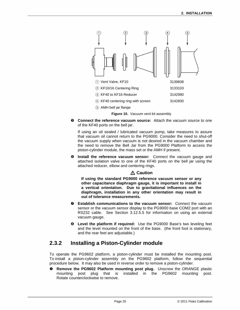
2. INSTALLATION
Page 25 © 2011 Fluke Calibration
Vent Valve, KF10
KF10/16 Centering Ring
KF40 to KF16 Reducer
KF40 centering ring with screen
AMH bell jar flange
3139838
3133103
3142990
3142830
Figure 10. Vacuum vent kit assembly
Connect the reference vacuum source: Attach the vacuum source to one of the KF40 ports on the bell jar.
If using an oil sealed / lubricated vacuum pump, take measures to assure that vacuum oil cannot return to the PG9000. Consider the need to shut-off the vacuum supply when vacuum is not desired in the vacuum chamber and the need to remove the Bell Jar from the PG9000 Platform to access the piston-cylinder module, the mass set or the AMH if present.
Install the reference vacuum sensor: Connect the vacuum gauge and attached isolation valve to one of the KF40 ports on the bell jar using the attached reducer, elbow and centering rings.
Caution If using the standard PG9000 reference vacuum sensor or any other capacitance diaphragm gauge, it is important to install in a vertical orientation. Due to gravitational influences on the diaphragm, installation in any other orientation may result in out of tolerance measurements.
Establish communications to the vacuum sensor: Connect the vacuum sensor or the vacuum sensor display to the PG9000 base COM2 port with an RS232 cable. See Section 3.12.5.5 for information on using an external vacuum gauge.
Level the platform if required: Use the PG9000 Base’s two leveling feet and the level mounted on the front of the base. (the front foot is stationary, and the rear feet are adjustable.)
2.3.2 Installing a Piston-Cylinder module
To operate the PG9602 platform, a piston-cylinder must be installed the mounting post. To install a piston-cylinder assembly on the PG9602 platform, follow the sequential procedure below. It may also be used in reverse order to remove a piston-cylinder. Remove the PG9602 Platform mounting post plug. Unscrew the ORANGE plastic
mounting post plug that is installed in the PG9602 mounting post. Rotate counterclockwise to remove.
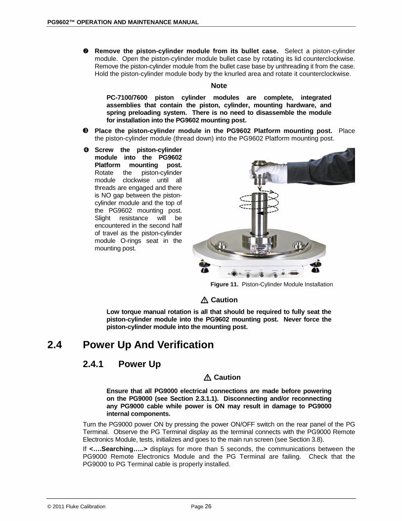
PG9602™ OPERATION AND MAINTENANCE MANUAL
© 2011 Fluke Calibration Page 26
Remove the piston-cylinder module from its bullet case. Select a piston-cylinder module. Open the piston-cylinder module bullet case by rotating its lid counterclockwise. Remove the piston-cylinder module from the bullet case base by unthreading it from the case. Hold the piston-cylinder module body by the knurled area and rotate it counterclockwise.
Note PC-7100/7600 piston cylinder modules are complete, integrated assemblies that contain the piston, cylinder, mounting hardware, and spring preloading system. There is no need to disassemble the module for installation into the PG9602 mounting post.
Place the piston-cylinder module in the PG9602 Platform mounting post. Place the piston-cylinder module (thread down) into the PG9602 Platform mounting post.
Screw the piston-cylinder module into the PG9602 Platform mounting post. Rotate the piston-cylinder module clockwise until all threads are engaged and there is NO gap between the piston-cylinder module and the top of the PG9602 mounting post. Slight resistance will be encountered in the second half of travel as the piston-cylinder module O-rings seat in the mounting post.
Figure 11. Piston-Cylinder Module Installation
Caution Low torque manual rotation is all that should be required to fully seat the piston-cylinder module into the PG9602 mounting post. Never force the piston-cylinder module into the mounting post.
2.4 Power Up And Verification
2.4.1 Power Up Caution
Ensure that all PG9000 electrical connections are made before powering on the PG9000 (see Section 2.3.1.1). Disconnecting and/or reconnecting any PG9000 cable while power is ON may result in damage to PG9000 internal components.
Turn the PG9000 power ON by pressing the power ON/OFF switch on the rear panel of the PG Terminal. Observe the PG Terminal display as the terminal connects with the PG9000 Remote Electronics Module, tests, initializes and goes to the main run screen (see Section 3.8). If <….Searching…..> displays for more than 5 seconds, the communications between the PG9000 Remote Electronics Module and the PG Terminal are failing. Check that the PG9000 to PG Terminal cable is properly installed.

2. INSTALLATION
Page 27 © 2011 Fluke Calibration
If PG900 fails to reach the main run screen, service may be required. Record the sequence of operations and displays observed and contact a Fluke Calibration Authorized Service Provider (see Table 28).
2.4.2 Verify correct Piston-Cylinder and Mass Set Information
PG9000 uses stored piston-cylinder and mass set metrological information to calculate the reference pressures it defines (see Section 3.1). For the pressure values to be correct, the stored metrological information on the piston-cylinder, mass set and mass loading bell must be correct. Before using PG9000 for accurate pressure definition, the validity of the stored information should be verified. This consists of comparing the piston-cylinder, mass set and mass loading bell information stored in PG9000 to the information in the piston-cylinder and mass set calibration reports. To verify the PG9000 piston-cylinder, mass set and mass loading bell information, use the piston-cylinder and mass set viewing capabilities accessed by pressing [SPECIAL], <1PC/MS> (see Section 3.12.1). Compare all the information contained in the PG9000 piston-cylinder, mass set and mass loading bell files to the information on the current piston-cylinder, mass set and mass loading bell calibration reports.
2.4.3 Set Local Gravity Value PG9000 uses the value of local acceleration due to gravity (gl) in its calculation of the reference pressure (see Section 3.1). The correct value of local acceleration due to gravity at the site of PG9000 use must be entered. This is accomplished by pressing [SPECIAL], <6gl> (see Section 3.12.6) and editing the value of local gravity. Edits to this value may be locked out due to user access level restrictions. See section 3.12.4.5 for how to change access level restrictions. Set the access restriction to “none” and then return to editing the value of local gravity.
2.4.3.1 Check/Set Security Level PG9000 has a security system based on User Levels. By default, the security system is set to “low” and no password is required to change the security level. This level locks out edits to critical metrological data. See Section 3.12.4.5 for information on the security system. As part of the PG9000 startup, set your desired security level and a password.
Caution PG9000 is delivered with the security level set to low to avoid inadvertent altering of critical internal settings but with access to changing security levels unrestricted. It is recommended that the “low” security level be maintained at all times and password protection be implemented if control over setting of security levels is desired.
2.4.4 Verify Input Sources PG9000 uses many variables in calculating defined pressures. The sources of the variables are determined by the current SETUP file. SETUP files are viewed, created, edited and selected using the SETUP function accessed by pressing [SETUP] (see Section 3.11). By default, the factory SETUP file is selected on a new PG9000, but the operator may desire to customize the settings by creating a new setup file. The factory setup file assumes that PG9000’s internal measurement values will be used whenever possible.
PG9602™ OPERATION AND MAINTENANCE MANUAL
© 2011 Fluke Calibration Page 28
2.4.5 Verify Proper Operation of Ambient Conditions Measurements
PG9000 automatically measures ambient conditions and uses these conditions in its pressure calculations. To verify that the ambient condition measurements are operating properly proceed as follows: • Display current ambient condition readings: Press the [AMBIENT] key. The ambient
conditions run screen is displayed (see Section 3.10.6). • Verify proper ambient condition readings: Compare the ambient condition values
displayed to the actual values of ambient conditions. Refer to the ambient condition measurement specifications when evaluating the ambient readings (see Section 1.2.1.3).
Note • The unit of measure in which ambient pressure is displayed is the same as
the unit selected by pressing [UNIT] (see Section 3.10.3). Units of measure in which other ambient condition values are expressed cannot be changed.
• PG9000 allows the source of ambient condition values used in reference pressure calculations to be specified. The source may be PG9000’s on-board measurements, a normal value or operator entered values. See Section 3.11 for information on specifying the source of ambient condition values used by PG9000 in reference pressure calculations.
2.4.6 Apply Pressure To The Piston-Cylinder Module Note
This section assumes the use of a manual mass set and that the PG9000 system assembly has been completed, including pressure interconnection (see Section 2.3). If an AMH mass set is being used, then the AMH-100 operation must first be verified before proceeding. Jump to Section 2.4.10 for initializing and verifying AMH operation.
Caution Before applying pressure to the PG9000 system, be sure that all pressure vessels and connections are rated for the pressure that will be applied and that all connections have been properly tightened.
Continuing with the PG9000 verification process requires applying pressure to the piston-cylinder module and floating the piston. Proceed as follows: Turn OFF automated piston rotation and automated pressure generation (if
present). This will prevent the automated rotation and pressure generation features from interfering during verification of these features (see Sections 3.10.8 and 3.10.9 for information on automated piston rotation and pressure generation).
Load mass on the piston. Install the mass loading bell on the piston if it’s not already loaded. Then load the make up mass (4 or 9 kg) (see Section 2.3.1.3).
Float the piston. Use the pressure generation/control component of the PG9000 system to apply pressure under the piston through the PG9000 Platform TEST port. The piston will float at a pressure approximately equal to the piston’s mass-to-pressure conversion factor multiplied by the mass load in kg. The piston-cylinder conversion factor is marked on the top of the piston cap and is in units of kPa per kilogram [kPa/kg].
2. INSTALLATION
Page 29 © 2011 Fluke Calibration
Note • It may be required to manually rotate the mass by hand to help the piston
achieve a proper float. • If the piston cannot be floated because it immediately sinks down from
a float position, there is a leak in the pressure system. Identify and eliminate leak(s) until the piston drop rate is less than the nominal fall rate given in the specifications of the piston-cylinder module being used (see Section 1.2.2).
2.4.7 Check Proper Behavior Of Motorized Piston Rotation The motorized rotation feature can be enabled to automatically engage and disengage as needed to maintain the piston rotation rate when the piston is floating. The feature is also used to stop rotation before a mass manipulation event as would be required to set a different pressure (see Section 3.10.8). Motorized piston rotation can also be activated manually by pressing and holding [ ]. Stopping piston rotation can be manually activated by pressing and holding [ ] and then pressing [←] (see Section 3.10.13). Confirm the automated rotation is still off. If not, turn automated rotation OFF by pressing [ROTATE] and selecting <1off>. The selection will alternate between On and Off depending on the current state of the rotation feature. Load at least the mass bell on the piston, float the piston and press [ ]. When the piston is floating, the motorized rotation system should engage and cause the mass bell and piston to begin rotating. Within 5 to 30 seconds, depending on the mass load, the rotation rate should reach about 50 rpm. Current rotation rate can be observed by pressing [SYSTEM] (see Section 3.10.5).
2.4.8 Verify Proper Operation Of Piston Behavior Measurements
Float the piston and rotate it (see Sections 2.4.6 and 2.4.7). • Press [SYSTEM] once to reach the first SYSTEM run screen. Verify that the piston
position, piston drop rate, piston rotation rate and piston rotation decay rate are indicating correctly (see Section 3.10.5). The piston position sensing system may be calibrated using an on-board procedure if necessary (see Section 5.2.2). Calibration of piston position is recommended when installing a new PG9000 and as part of regular maintenance after installation.
• Press [SYSTEM] again to reach the second SYSTEM run screen. Verify that the piston-cylinder temperature and temperature rate of change are indicating correctly (see Section 3.10.5).
2.4.9 Verify Vacuum Reference PG9000 includes provisions for establishing and measuring a vacuum reference. It is important to verify the system is able to pull a sufficiently low vacuum. To verify the vacuum reference capability: Install a piston-cylinder module (see Section 2.3.2). Install the bell jar on the PG9000 Base (the bell jar aligns on the PG9000 vacuum plate
and seals itself). Add a reference vacuum sensor to one of the KF40 ports on the bell jar (see Section 2.3.1.5). Apply a vacuum through another KF40 port on the bell jar, sealing other bell jar openings
with caps. Press [SYSTEM] twice to observe the value of vacuum read by the vacuum gauge.

PG9602™ OPERATION AND MAINTENANCE MANUAL
© 2011 Fluke Calibration Page 30
Note The vacuum sensor (CDG) is assembled to an isolation valve in order to store and/or transport in an evacuated condition. In order to assure performance within specifications, open the valve only when the pressure in the attached vacuum chamber is below 500 Pa and close the valve before venting the chamber pressure from vacuum back to atmosphere.
If a vacuum pump of adequate capacity has been correctly connected to the reference vacuum port, the vacuum read by the PG9000 vacuum sensor should go to 4 Pascal [Pa] or lower in five minutes on the first pump down and two to three minutes on immediate subsequent pump downs. If this performance is NOT achieved: • The vacuum pump may be inadequate. • The connection of the vacuum pump to the PG9000 bell jar may have leaks or excessive
restrictions. • The PG9000 vacuum gauge may be incorrect. • There may be a leak in the PG9000.
2.4.10 AMH Initialization / Startup Caution
Perform an AMH initialization before loading the AMH over the masses (see Section 2.4.10).
Initializing the AMH prior to installing it over the masses is a good practice to ensure the mass manipulation mechanisms will not interfere with the masses. The process is used to check that the AMH binary mass pins are fully retracted and the main mass columns are rotated correctly in that the flat surface of each column is facing in towards the middle of the AMH. The first part of the initialization process is to visually verify the position of the binary mass pins and the mass columns. This is performed with the AMH resting on it’s side so that it’s easier to look up inside the binary pin actuator assembly. The AMH must be electrically and pneumatically connected to perform the verification.
Caution A drive vacuum supply must be connected to AMH VENT when using a PG9000 in “absolute by vacuum” mode. Always check that the AMH is supplied with drive vacuum before establishing reference vacuum in the AMH vacuum chamber. Failure to do so may result in damage to the binary mass pins and/or binary masses.
To verify the AMH mass handler prior to installing it on the PG9000 Platform, proceed as follows:
Make the necessary pneumatic, power and communications connections: Complete the set up procedure described in Section 2.3.1.
Caution Do not operate AMH with drive pressure lower than 275 kPa (40 psi). Damage to the AMH could result. For an AMH-100, the recommended minimum drive pressure is 80 psi.
Insert the mass lifting shaft into the AMH: Insert the shaft into the hole in the center of the AMH mass lifter and slide it down until the trim mass tray sits on the top of the lifter. This arrangement trips the AMH’s internal proximity sensor allowing the AMH system to be operated off of the PG9000 Platform without an actual mass load. If the AMH is laid on its side, then the mass loading tray will need to be held in place by the operator while the initialization routine executes.
2. INSTALLATION
Page 31 © 2011 Fluke Calibration
Select an AMH mass set and mass bell as the active mass set and bell for the PG9000: This step can be skipped if the AMH mass set and bell have already been selected, if so go directly to step . On the PG Terminal, press [SPECIAL], <1PC/MS>, <3mass bell>, <5select> and select the mass bell of the AMH mass set. Using [SPECIAL], <1PC/MS>, <2mass set>, <5select>, select an AMH mass set (mass set designated by S/N nnnnA). Selecting the AMH mass set causes the PG9000 Platform to attempt to establish communication with the AMH system, and if successful the AMH will automatically go through the self-initialization routine. If the communication fails, an error message occurs (see Sections 3.7.2.8, 6).
If communication succeeds, the PG9000 initializes the AMH mass handler. The trim mass tray should rise approximately 2.5 cm (1 in.) above the top of the lifter; followed by the sound of the main mass selection columns rotating. Then the trim mass tray is lowered back down. The steps of this procedure are commented on the PG Terminal display as they execute. If the sequence does not complete and/or any error messages are observed, see Section 6 and Table 10 for troubleshooting assistance. If the sequence completes, the AMH system has been cleared and put into a known state in which all mass holding ledges and pins are retracted so that it can safely be slipped down over the AMH mass set and installed on the PG9000 Platform.
The PG9000 Platform must be able to initialize the AMH system before start up can proceed.
Clear the AMH and test its operation: Press [SPECIAL], <8AMH>, <2control>, <3loadall>. The trim mass tray should rise approximately 2.5 cm (1 in.) above the top of the lifter, followed by the sound of the main mass selection columns rotating. Then the trim mass tray should be lowered back down.
Note • The <3loadall> selection executes the same initialization routine as used
when an AMH mass set is selected. • Become familiar with the “[SPECIAL], <8AMH>, <2control>, <3loadall>”
menu selection as it is recommended to be used every time the AMH is to be removed from or placed on the PG9000 platform.
The steps of this procedure are commented on the PG Terminal display as they occur. If the sequence does not complete and/or any error messages are observed, see Section 6 and Table 10 for troubleshooting assistance. If the sequence completes, the AMH mass handler has been cleared and put into a known state in which all mass holding ledges and pins are retracted so that it can safely be slipped down over the mass set and installed on the PG9000 Platform.
Visually inspect the binary mass pins and mass columns.
Visually inspect the condition of the AMH mass handler by carefully tipping the AMH to look inside. The main mass columns should all have the surfaces (no ledges) facing towards the center and all binary mass selection pins should be retracted (see Section 3.7.1).
When this step is complete, the AMH is ready to be installed on the PG9000 Platform (see Section 3.7.2.1).
2.4.11 Check Automated Pressure Generation If hardware is available for automatically generating the pressure and floating the piston, then proceed with verifying operation.
Caution Before applying pressure to the PG9000 system, be sure that all pressure vessels and connections are rated for the pressure levels that will be applied and that all connections have been properly tightened.
PG9602™ OPERATION AND MAINTENANCE MANUAL
© 2011 Fluke Calibration Page 32
To check automated pressure generation/control: Verify that the automated pressure generation/control component is properly connected
to the system (see Section 2.3.1.2). When operation has returned to the main run screen, turn ON automated pressure generation
control by pressing [GEN] and selecting <1on> (see Section 3.10.9). If not already enabled, turn on the automated ration feature by pressing [ROTATION] and selecting <1on>.
Press [P OR M], <1pressure> to select pressure entry mode (see Section 3.10.12). Press [ENT] and enter a pressure value to be generated. If using a manual mass set then follow the mass loading instruction (see Section 3.6).
Verify the pressure generation/control component properly generates pressure and floats the PG9000 piston.
2.4.12 Setup Verification Step to Take Before Making Pressure Measurements
Before using PG9000 to make accurate pressure measurements, consider the following: • Select/activate the correct piston-cylinder module, mass set and mass loading bell
(see Sections 3.10.2, 3.12.1.10, 3.12.1.15). Verify the piston-cylinder installed in the mounting post is the active piston-cylinder data set being used by the PG9000 by pressing the [P-C] key.
• If using an automated pressure generation/control component with automated pressure generation, set the pressure controller’s upper limit (UL) (see Section 3.10.9.3).
• Enter the correct value of local gravity for the site of use (see Section 3.12.6). • Consider head corrections (see Sections 3.10.7 and 3.12.3). • Level the PG9000 Platform (see Section 2.3.1.1). • Select the correct pressure unit of measure and measurement mode (see Sections
3.10.3 and 3.10.4). • Verify that the settings for the sources of variables to be used by PG9000 in its
calculations of reference pressures are those desired (see Section 3.11). • Verify that the piston-cylinder module is correctly cleaned and operating properly
(see Section 5.3). • Verify that there are NO leaks in the pressure system.
2.5 Short Term Storage The following is recommended for short term storage of PG9000.
Remove all masses from the PG9000 Platform (manual mass set only) and cover them. Vent all pneumatic circuits to atmosphere. Turn OFF power using the power switch on the rear of the PG9000 Terminal.
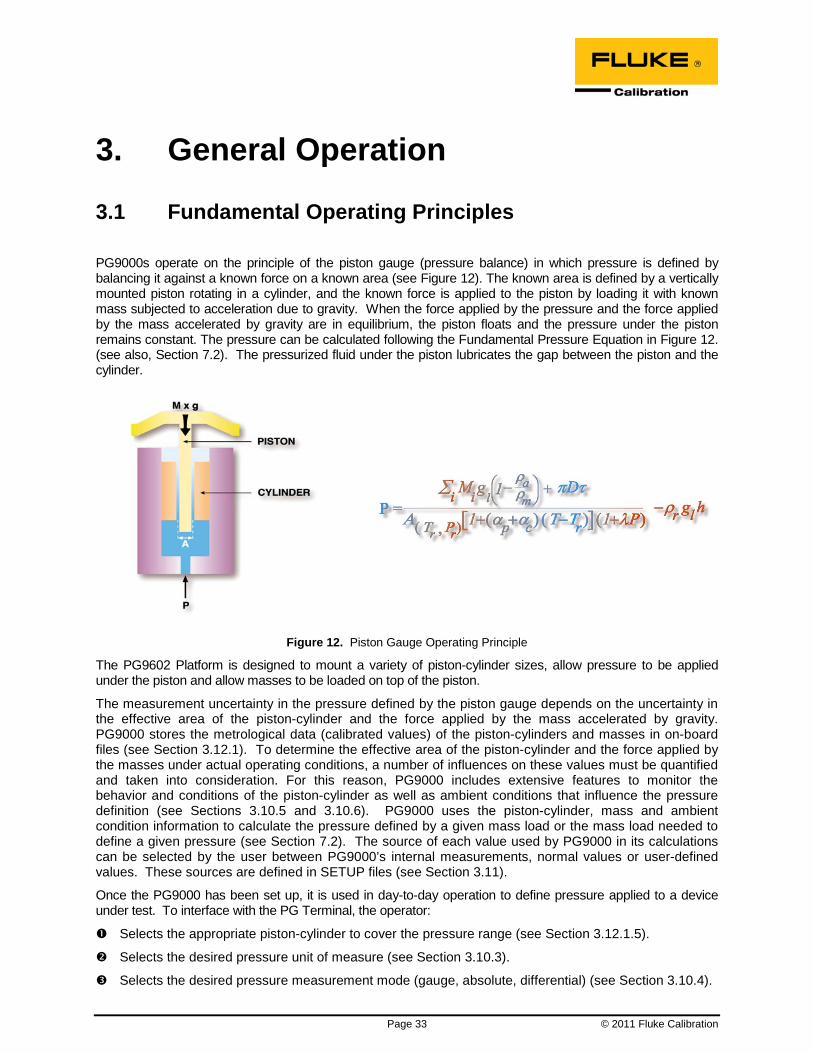
Page 33 © 2011 Fluke Calibration
3. General Operation
3.1 Fundamental Operating Principles
PG9000s operate on the principle of the piston gauge (pressure balance) in which pressure is defined by balancing it against a known force on a known area (see Figure 12). The known area is defined by a vertically mounted piston rotating in a cylinder, and the known force is applied to the piston by loading it with known mass subjected to acceleration due to gravity. When the force applied by the pressure and the force applied by the mass accelerated by gravity are in equilibrium, the piston floats and the pressure under the piston remains constant. The pressure can be calculated following the Fundamental Pressure Equation in Figure 12. (see also, Section 7.2). The pressurized fluid under the piston lubricates the gap between the piston and the cylinder.
Figure 12. Piston Gauge Operating Principle
The PG9602 Platform is designed to mount a variety of piston-cylinder sizes, allow pressure to be applied under the piston and allow masses to be loaded on top of the piston.
The measurement uncertainty in the pressure defined by the piston gauge depends on the uncertainty in the effective area of the piston-cylinder and the force applied by the mass accelerated by gravity. PG9000 stores the metrological data (calibrated values) of the piston-cylinders and masses in on-board files (see Section 3.12.1). To determine the effective area of the piston-cylinder and the force applied by the masses under actual operating conditions, a number of influences on these values must be quantified and taken into consideration. For this reason, PG9000 includes extensive features to monitor the behavior and conditions of the piston-cylinder as well as ambient conditions that influence the pressure definition (see Sections 3.10.5 and 3.10.6). PG9000 uses the piston-cylinder, mass and ambient condition information to calculate the pressure defined by a given mass load or the mass load needed to define a given pressure (see Section 7.2). The source of each value used by PG9000 in its calculations can be selected by the user between PG9000’s internal measurements, normal values or user-defined values. These sources are defined in SETUP files (see Section 3.11).
Once the PG9000 has been set up, it is used in day-to-day operation to define pressure applied to a device under test. To interface with the PG Terminal, the operator:
Selects the appropriate piston-cylinder to cover the pressure range (see Section 3.12.1.5).
Selects the desired pressure unit of measure (see Section 3.10.3).
Selects the desired pressure measurement mode (gauge, absolute, differential) (see Section 3.10.4).

PG9602™ OPERATION AND MAINTENANCE MANUAL
© 2011 Fluke Calibration Page 34
Sets the head difference between the PG9000 and the device under test (see Section 3.10.7).
Selects mass-to-pressure or pressure-to-mass operating mode (see Section 3.10.12).
Enters a pressure to define or a current mass load to calculate (see Section 3.10.11.1 and 3.10.11.2).
Loads masses by hand or with optional AMH (Automated Mass Handler), floats the piston and defines pressure.
3.2 Keypad Layout And Protocol PG9000 has a 4 x 4 keypad for local operator access to direct functions, function menus and for data entry.
The Function/Data keys allow very commonly used functions to be accessed directly from the main run screen by a single keystroke. The name of the function is on the bottom half of the key (see Section 3.10.1). These keys enter numerical values when editing.
The Editing and Execution keys are for execution, suspending execution, backing up in menus and editing entries.
The Menu/Data keys provide access to function menus from the main run screen. The menu name is on the bottom half of the key. The SPECIAL menu is for more frequently used functions. The SETUP menu is for functions that are NOT generally used as a part of day to day operation. These keys enter numerical values when editing.
Figure 13. PG9000 Keypad Layout
Key press confirmation is provided by both tactile and audible feedback. A single beep confirms a valid entry. A descending two note tone signals an invalid entry. The audible valid entry feedback can be suppressed or modified by pressing [SPECIAL] and selecting <5prefs>, <2sound> (see Section 3.12.4.2).
Pressing the [ENT/SET P] key generally causes execution or forward movement in the menu tree. [ENT/SET P] is also used to enter a command to set a pressure.
Pressing the [ESC] key generally allows movement back in the menu tree and/or causes execution to cease or suspend without changes being implemented. Pressing [ESC] repeatedly eventually returns to the main run screen. From the main run screen, pressing [ESC] allows momentary viewing of the PG9000 identification screen.
Pressing the [+/-] key changes a numerical sign when editing. It also toggles through multiple screens when available.
Pressing the [←] and [→] keys when editing allows reverse and forward cursor movement when editing data entry. These keys are also used to scroll through choices.
Menu selections can be made by pressing the number of the selection directly or by pressing [←] and [→] to place the cursor on the number of the desired selection and pressing [ENT].
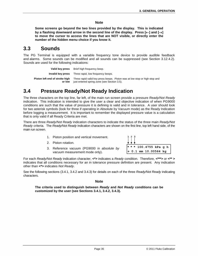
3. GENERAL OPERATION
Page 35 © 2011 Fluke Calibration
Note Some screens go beyond the two lines provided by the display. This is indicated by a flashing downward arrow in the second line of the display. Press [←] and [→] to move the cursor to access the lines that are NOT visible, or directly enter the number of the hidden menu choice if you know it.
3.3 Sounds The PG Terminal is equipped with a variable frequency tone device to provide audible feedback and alarms. Some sounds can be modified and all sounds can be suppressed (see Section 3.12.4.2). Sounds are used for the following indications:
Valid key press Brief high frequency beep.
Invalid key press Three rapid, low frequency beeps.
Piston left end of stroke high or low
Three rapid valid key press beeps. Piston was at low stop or high stop and just entered spring zone (see Section 3.5).
3.4 Pressure Ready/Not Ready Indication The three characters on the top line, far left, of the main run screen provide a pressure Ready/Not Ready indication. This indication is intended to give the user a clear and objective indication of when PG9000 conditions are such that the value of pressure it is defining is valid and in tolerance. A user should look for two asterisk symbols (look for three if operating in Absolute by Vacuum mode) as the Ready Indication before logging a measurement. It is important to remember the displayed pressure value is a calculation that is only valid if all Ready Criteria are met.
There are three Ready/Not Ready indication characters to indicate the status of the three main Ready/Not Ready criteria. The Ready/Not Ready indication characters are shown on the first line, top left hand side, of the main run screen.
1. Piston position and vertical movement.
2. Piston rotation.
3. Reference vacuum (PG9000 in absolute by vacuum measurement mode only).
* * * 100.4755 kPa g h + 0.1 mm 10.00564 kg
For each Ready/Not Ready indication character, <*> indicates a Ready condition. Therefore, <***> or <** > indicates that all conditions necessary for an in tolerance pressure definition are present. Any indication other than <*> indicates Not Ready.
See the following sections (3.4.1, 3.4.2 and 3.4.3) for details on each of the three Ready/Not Ready indicating characters.
Note The criteria used to distinguish between Ready and Not Ready conditions can be customized by the user (see Sections 3.4.1, 3.4.2, 3.4.3).

PG9602™ OPERATION AND MAINTENANCE MANUAL
© 2011 Fluke Calibration Page 36
3.4.1 Piston Position Ready/Not Ready The piston position Ready/Not Ready character indicates Ready or Not Ready based on the float position of the piston (see Section 3.5) and an automated measure generation status (see Section 3.10.9). This ensures that pressure definitions will be made with the piston not more than a certain distance from mid-float position and that measurements will not be made while the action of an automated pressure controller is active which may influence the pressure. The default ready range is -2.5 mm to +2.5 mm relative to the center float position of 0.0 mm. The piston position Ready/Not Ready character is the first character from the left on the top line of the main run screen. The piston position Ready/Not Ready criterion is determined by the current SETUP file and can be customized by the user (see Section 3.11). Piston position Ready/Not Ready character indications include: < * > Piston position Ready (within the position limits specified in the current SETUP file)
(see Section 3.5). <↓> Piston position Not Ready, low (below the position limits specified in the current
SETUP file, see Section 3.11). The <↓> flashes if the piston is not at the bottom stop position to alert the user that this indicator is Not Ready.
<↑> Piston position Not Ready, high (above the position limits specified in the current SETUP file) (see Section 3.11). The <↑> flashes if the piston is not at the top stop position to alert the user that this indicator is Not Ready.
<?> Piston position not known (current specified mass load is less than the load of the piston + bell). The mass carrying bell must be installed for PG9000 piston position measurement to operate correctly – any random piston position values that may be indicated are not valid when the mass carrying bell is not installed.
Note Piston position always indicates Not Ready if automated pressure generation is adjusting pressure, regardless of actual piston position.
3.4.2 Piston Rotation Rate Ready/Not Ready The piston rotation Ready/Not Ready character indicates Ready or Not Ready based on the rotation rate of the piston. The piston rotation Ready/Not Ready character is the second character from the left on the top line of the main run screen. The piston rotation rate Ready/Not Ready criterion is specific to the currently active piston cylinder module and can be edited by the user (see Sections 3.12.1.1). Piston rotation rate Ready/Not Ready character indications include: < * > Rotation rate Ready: Rotation rate is within the rotation rate limits specified in the
current piston-cylinder module file) (see Section 3.12.1.1). <<> Rotation rate Not Ready, low: Rotation rate is less than the lower rotation rate limit
specified in the current piston-cylinder module file (see Section 3.12.1.1) or motorized rotation system is currently engaged. Note that the low rotation limit is automatically reduced when the mass loaded on the piston is less than 3 kg. The <<> flashes if the piston is floating to alert the user that this indicator is Not Ready.
<?> Rotation rate not known: Current specified mass load is less than the load of the (piston + bell). The bell must be installed for PG9000 piston rotation rate measurement to operate correctly so piston rotation rate cannot be measured when the bell is not installed.
Note At mass loads less than 3 kg the low rotation limit is automatically reduced to an operational minimum to maximize free rotation time.
3. GENERAL OPERATION
Page 37 © 2011 Fluke Calibration
3.4.3 Vacuum Reference Ready/Not Ready The vacuum reference Ready/Not Ready is only active when operating in absolute by vacuum mode (see Section 3.10.4). The vacuum reference Ready/Not Ready character indicates Ready or Not Ready based on the value of reference vacuum when making measurements in absolute by vacuum mode. This ensures that definitions of absolute pressure with a vacuum reference will be made with the vacuum under the PG9000 bell jar lower than a specified value. When the vacuum is not low enough, vacuum measurement errors may be excessive. The vacuum reference Ready/Not Ready character is the third character from the left on the top line of the main run screen. The vacuum reference Ready/Not Ready criterion is determined by the current SETUP file and can be customized by the user (see Section 3.11). The vacuum reference criterion is a fixed value that can be customized by the user when the vacuum reference selection in the SETUP file is COM2. If the selection in the SETUP file is user or normal, the vacuum reference Ready/Not Ready character always indicates Ready and the value cannot be customized. Vacuum reference Ready/Not Ready character indications include: < > (Blank) Vacuum reference is not in use. The selected measurement mode is not
absolute by vacuum. < * > Vacuum reference Ready. Vacuum value is below limit specified in the current
SETUP file if source is COM2 or user (not a measured value) (see Section 3.11). < > > Vacuum reference Not Ready. Current SETUP file source for vacuum is COM2
and vacuum value is above the limit specified (see Section 3.11). The <>> flashes if the piston is floating to alert the user that this indicator is Not Ready.
3.5 Piston Position When operating a PG9000 piston gauge, reference pressure values are defined by loading known mass values on the piston and adjusting the pressure to float the piston. Piston position is measured and displayed real time on the MAIN run screen (see Section 3.8) and in the first SYSTEM run screen (see Section 3.10.5.1). Piston position is used as a criterion for the Ready/Not Ready indication as valid measurements can only be made when the piston is in the correct position (see Section 3.4.1).
The position sensing technology is prone to drift over time and therefore it is important to periodically adjust the min/max limits of the piston position sensor. When using an AMH, this maintenance requirement takes on added importance. Please see section 5.2.2 for details on this maintenance requirement.
The full piston stroke is ± 4.5 mm from the midstroke position. The stroke is divided into different positions and zones as illustrated in Figure 14. These zones are:
• High and low stops: The piston is at the minimum or maximum end of travel stroke. These are mechanical stops that part of the piston-cylinder module. The pressure applied to the piston is higher (at high stop) or lower (at low stop) than that corresponding to the mass loaded on the piston. The high and low stop positions are fixed.
• High and low spring zones: The combination of pressure and the force of the high or low stop springs have caused the piston to move away from the mechanical stop. The pressure applied to the piston is within the equivalent of 2 kg of the pressure corresponding to the mass loaded on the piston. The high and low spring zones indicate the piston is about to float. The spring zone positions are fixed.
• High and low measurement zones: The piston is within the zone in which a Ready condition is valid and a measurement can be made (see Section 3.4.1). The pressure applied to the piston is the same as the calculated pressure as defined by solving the fundamental pressure equation. The default value of the high and low measurement zones is ± 2.5 mm centered around the midstroke position. This value can be adjusted in the SETUP file (see Section 3.11).
• Midstroke: The piston is at the middle of the float zone. The reference level as marked on the PG9000 mounting post corresponds to the bottom of the piston when it’s at the midstroke position.
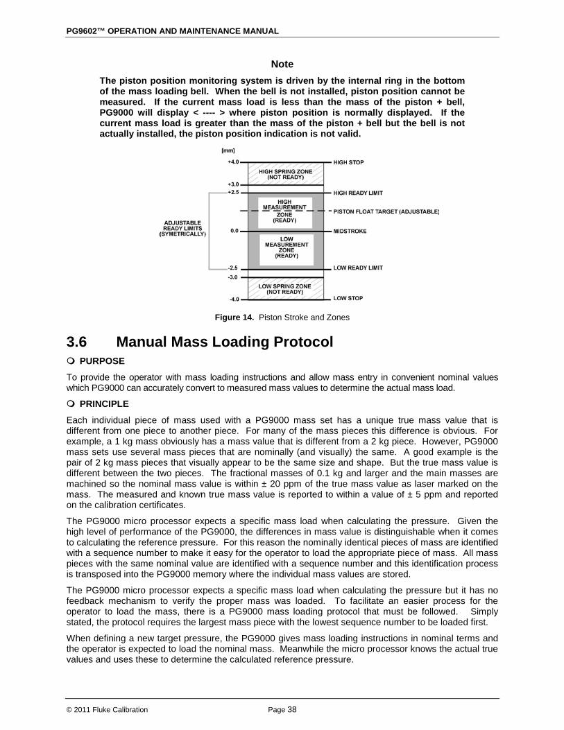
PG9602™ OPERATION AND MAINTENANCE MANUAL
© 2011 Fluke Calibration Page 38
Note The piston position monitoring system is driven by the internal ring in the bottom of the mass loading bell. When the bell is not installed, piston position cannot be measured. If the current mass load is less than the mass of the piston + bell, PG9000 will display < ---- > where piston position is normally displayed. If the current mass load is greater than the mass of the piston + bell but the bell is not actually installed, the piston position indication is not valid.
Figure 14. Piston Stroke and Zones
3.6 Manual Mass Loading Protocol PURPOSE
To provide the operator with mass loading instructions and allow mass entry in convenient nominal values which PG9000 can accurately convert to measured mass values to determine the actual mass load.
PRINCIPLE
Each individual piece of mass used with a PG9000 mass set has a unique true mass value that is different from one piece to another piece. For many of the mass pieces this difference is obvious. For example, a 1 kg mass obviously has a mass value that is different from a 2 kg piece. However, PG9000 mass sets use several mass pieces that are nominally (and visually) the same. A good example is the pair of 2 kg mass pieces that visually appear to be the same size and shape. But the true mass value is different between the two pieces. The fractional masses of 0.1 kg and larger and the main masses are machined so the nominal mass value is within ± 20 ppm of the true mass value as laser marked on the mass. The measured and known true mass value is reported to within a value of ± 5 ppm and reported on the calibration certificates.
The PG9000 micro processor expects a specific mass load when calculating the pressure. Given the high level of performance of the PG9000, the differences in mass value is distinguishable when it comes to calculating the reference pressure. For this reason the nominally identical pieces of mass are identified with a sequence number to make it easy for the operator to load the appropriate piece of mass. All mass pieces with the same nominal value are identified with a sequence number and this identification process is transposed into the PG9000 memory where the individual mass values are stored.
The PG9000 micro processor expects a specific mass load when calculating the pressure but it has no feedback mechanism to verify the proper mass was loaded. To facilitate an easier process for the operator to load the mass, there is a PG9000 mass loading protocol that must be followed. Simply stated, the protocol requires the largest mass piece with the lowest sequence number to be loaded first.
When defining a new target pressure, the PG9000 gives mass loading instructions in nominal terms and the operator is expected to load the nominal mass. Meanwhile the micro processor knows the actual true values and uses these to determine the calculated reference pressure.
3. GENERAL OPERATION
Page 39 © 2011 Fluke Calibration
OPERATION
Simply stated, the protocol requires the largest mass piece with the lowest sequence number to be loaded first. When defining a new target pressure, the PG9000 gives mass loading instructions in nominal terms and the operator is expected to load the nominal mass. The mass load instructions are for the total mass load – it is not
To summarize the following rules and examples:
an incremental mass change relative to the previous mass load.
• Always load the make up mass first when possible (mass load must be 5 kg (10 kg if using the larger mass sets) or greater). For all higher pressure points, the make up mass remains on the bottom of the loaded mass stack.
• Always load the lowest sequence number when given a choice of identical nominal masses.
• Keep the large masses on the bottom of the stack and change out the smaller fractional masses as required for each mass load.
Note To avoid wear to masses and to the piston-cylinder module end of stroke stops, the piston should not be rotating when masses are loaded or unloaded. Before loading masses, stop piston rotation by hand or using the motorized rotation system (see Section 3.10.13).
In pressure-to-mass mode, the instruction of the mass to load to achieve the requested pressure is formatted:
Load nominal mass: kkk.k kg and gg.gg g
In mass-to-pressure mode, the entry of the mass currently loaded on the piston is formatted:
Nominal mass load: kkk.k kg and gg.gg g
kkk.k and gg.gg must be expressed and loaded following the mass loading rules below:
See Sections
Mass Loading Rules
2.3.1.3, Installing Masses On The Mass Loading Tray 3.6 and . for PG9000 mass set principles and protocol information. Refer to display examples immediately above to identify kkk.k and gg.gg.
See EXAMPLES: Mass Loading below for mass loading examples.
PG9000 mass loading entries and instructions are always formatted: kkk.k kg and nn.nn g
• The mass set being used must be selected as the active mass set (see Section 3.12.1.10) and must be properly set up prior to use (see Section 3.12.1.6).
• kkk.k is made up of the piston, the mass loading bell and mass set masses of 0.1 kg and greater.
• kkk.k always includes the mass loading bell and then the makeup mass, if possible.
• kkk.k is made up of the largest masses possible rather than a combination of smaller masses.
EXAMPLE: To load 10.0 kg on a PG9602:
• USE the piston (0.2 kg) + the mass loading bell (0.8 kg) + the 9 kg makeup mass.
(assuming a 80 kg or larger mass set)
• DO NOT USE the piston + the mass loading bell + 5 kg + 2 kg #1 + 2 kg #2.
• When several masses of the same nominal value are included in kkk.k, they are loaded in numerical sequence, low to high.
• USE 10 kg mass #1, #2 and #3.
EXAMPLE: When loading three 10 kg masses:
• DO NOT USE 10 kg mass #4, #3, #1.
• This rule will be followed automatically if masses are installed and used as described in Section 2.3.1.3.

PG9602™ OPERATION AND MAINTENANCE MANUAL
© 2011 Fluke Calibration Page 40
• gg.gg is made up of mass from the gram trim mass set (masses of 50 g to 0.01 g). These masses can be loaded in any order.
Caution When PG9000 provides mass loading instructions and calculates the actual true mass of the requested load, it assumes that the mass set in use has been set up correctly (see Section 2.3.1.3). For PG9000 mass loading protocol to operate properly, the mass set in use must be EXACTLY the mass set that has been defined by the add and/or edit mass function (see Section 3.12.1.6).
• Mass loading instruction using PG9602 and MS-7002-80 (80 kg) mass set:
EXAMPLE: Manual Mass Loading when using the low range 10 kPa/kg piston-cylinder:
47.9 kg and 10.45 g
Load:
piston (0.5 kg)
bell (0.8 kg)
9 kg #1 (makeup mass)
10 kg #1 through #3
5 kg #1
2 kg #1
0.5 kg #1
0.1 kg #1
10.45 g from trim mass set
3.7 AMH Mass Loading
3.7.1 Operating Principals Note
Numerical reference in this section refers to Figure 15. The purpose of the AMH system is to automatically load specified values of mass onto the PG9000 piston-cylinder. This is accomplished by a three step process of, 1) lifting the complete mass set up, off, and above the piston-cylinder to the mass selection position, 2) selecting the individual masses to be loaded and retained, and then, 3) placing the masses to be loaded back onto the piston. It uses pneumatic drive pressure to lift the mass stack and to actuate the binary mass retaining pins, and it uses an electric motor to rotate the main mass columns. To accomplish the mass lifting, selection and lowering function, the AMH mass handler uses four main sub-systems. • Electronic and electrical controls (7): The AMH electronic and electrical controls are
located just above the mass lifter, under a protective cap. These support the AMH operating logic, a proximity sensor to detect mass load position, reading of the main mass selection column switches, operation of the column rotating motor and actuation of the pneumatic control solenoid valves.
• Mass lifter (8): The mass lifter is used to lift the entire mass load up to the mass selection position and then to lower the selected masses onto the piston. The mass lifter is pneumatically driven. A flexible diaphragm (4) is connected to a lifting assembly (5). A three-way solenoid valve (9) is actuated to admit or exhaust drive air pressure to and from the volume under the diaphragm. Admitting drive pressure pushes the lifting assembly up. Exhausting the pressure lowers it. The pressure is exhausted outside of the vacuum chamber, to the AMH drive vacuum supply line.
3. GENERAL OPERATION
Page 41 © 2011 Fluke Calibration
• As the mass lifting assembly (5) rises, it engages a ledge on the mass lifting shaft (6), pushing it up. The mass lifting shaft is connected to the binary mass carrier (10) and the mass bell (1) sits on the binary mass carrier. As the mass lifting shaft goes up, it lifts the binary carrier and the bell, which in turn lifts the main masses (14) and the binary mass tubes (2). When the lifting assembly reaches the top of its stroke, so also is the entire mass load lifted completely off the piston cap (12) and the masses are in the mass selection position. In this position, the ledges on the main mass selection columns (13) align with the gaps between the main masses and the binary mass selector pins (3) align with the grooves in the binary mass tubes. When gas is exhausted from the volume under the lifting assembly, it descends, lowering the selected masses onto the piston.
• Main mass disc selection columns (13): The three main mass selection columns are used to retain the main mass discs (14) that are not to be loaded onto the piston. The columns are rotated synchronously by an electric motor and a drive belt (11). Contact switches are used to monitor the column position. Each column has ten sides. One side, which retains all the masses so that none are loaded, has a ledge for each mass. Each subsequent side has one less ledge, moving from the bottom up. The last side has no ledges and is used to select all the main masses for loading. (It is this smooth side that faces inward when an AMH initialization sequence is invoked.) When the mass load is lifted to the mass selection position, the motor is operated to rotate the columns to retain the desired number of masses. The rest of the main masses are free and are lowered back down onto the piston when the lifting assembly descends.
• Binary mass selection pins (3): The binary mass selection pins are used to retain the binary mass tubes that are not to be loaded onto the piston. Three pins for each mass are located in a circular pattern around the top of each mass. The pins are pneumatically actuated and double acting. Two three-way solenoid valves (9) control drive pressure to each set of three pins. One valve admits pressure to one side of the pin to extend it and the other admits pressure to the other side of the pin to retract it. Once the pins have been moved, the pressure is exhausted to the AMH vacuum vent line when there is reference vacuum under the bell jar. This prevents the reference vacuum from rising due a mass load change. When the mass load is lifted up to the mass selection position, the pins are operated to retain the binary masses that are not to be loaded. The rest of the binary masses are free and are placed back down onto the piston when the lifting assembly descends.
Warning Do not place fingers or anything else beneath the AMH trim mass tray. AMH may lower up to 100 kg (220 lbs) onto anything that is under the trim mass tray. This could cause damage and/or injury.
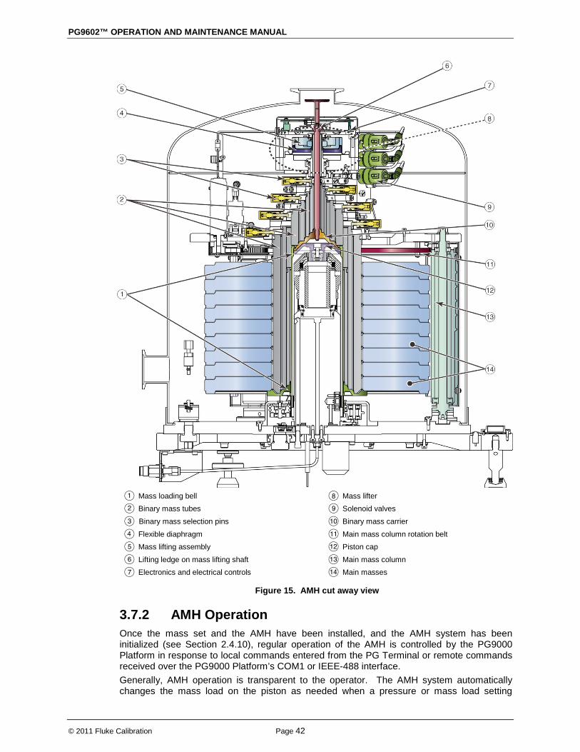
PG9602™ OPERATION AND MAINTENANCE MANUAL
© 2011 Fluke Calibration Page 42
Mass loading bell Binary mass tubes
Binary mass selection pins
Flexible diaphragm Mass lifting assembly
Lifting ledge on mass lifting shaft Electronics and electrical controls
Mass lifter Solenoid valves
Binary mass carrier
Main mass column rotation belt Piston cap
Main mass column Main masses
Figure 15. AMH cut away view
3.7.2 AMH Operation Once the mass set and the AMH have been installed, and the AMH system has been initialized (see Section 2.4.10), regular operation of the AMH is controlled by the PG9000 Platform in response to local commands entered from the PG Terminal or remote commands received over the PG9000 Platform’s COM1 or IEEE-488 interface. Generally, AMH operation is transparent to the operator. The AMH system automatically changes the mass load on the piston as needed when a pressure or mass load setting

3. GENERAL OPERATION
Page 43 © 2011 Fluke Calibration
command is given to the PG9000. The AMH and mass set are removed only when it is necessary to access the piston-cylinder assembly. Subsections of this section describe various aspects of AMH operation:
• Sections 3.7.2.1 and 3.7.2.2 -- installing and removing the AMH mass handler. • Section 3.7.2.3 -- pressure-to-mass or mass-to-pressure operation. • Section 3.7.2.4 -- controlling the AMH system directly, outside of pressure-to-mass or
mass-to-pressure operation. • Section 3.7.2.5 -- making and breaking the reference vacuum in AMH. • Section 3.7.2.6 -- accessing the piston-cylinder module when an AMH is installed. • Section 3.7.2.7 and 3.7.2.8 -- description of the indications of the AMH LED and a
listing of AMH related error messages. • Section 4.3.4.2 -- controlling PG9000 equipped with AMH by remote commands from
a computer.
3.7.2.1 Installing an AMH on the PG9000 Platform Caution
Perform an AMH initialization before loading AMH masses this ensures that AMH binary mass pins are retracted and the flat face of the main mass columns are facing inwards for loading. Installing the AMH over the masses before performing an AMH initialization risks damaging internal AMH components.
Figure 16. AMH Installation on PG9000 Platform

PG9602™ OPERATION AND MAINTENANCE MANUAL
© 2011 Fluke Calibration Page 44
To install the AMH on the PG9000 platform, proceed as follows (see Figure 16). Prepare the AMH: Before loading the masses, perform the AMH
initialization procedure described in Section 2.4.10. This assures that the AMH mass selection columns and pins are all correctly positioned. Make sure that the mass lifting shaft is NOT installed on the mass bell.
Lower the AMH onto the PG9000 Platform: Grasping the AMH by the horizontal platform in its middle, lift the AMH above the PG9000 platform and masses. Align it so that the cable and pneumatic connections line up with the connections on the rear side of the PG Base. Center the AMH over the mass load and gently lower it down until the AMH feet enter the holes in the PG9000 Platform. Assure that all three feet fully enter and seat in the platform holes. Tighten the platform set screws using a 2.5 mm allen wrench provided in the AMH accessories, one for each of the feet.
Install the mass lifting shaft: Slip the threaded end of the shaft down through the hole in the center of the mass lifter. Thread the shaft into the binary mass carrier by holding and rotating the trim mass tray. Note that shaft has a left hand thread so it must be rotated counter-clockwise to tighten it. Use the 3 mm allen wrench T-bar supplied in the AMH-100 accessories to tighten the assembly until you feel the mass start to rotate.
Caution
Be sure that the mass lifting shaft is fully threaded into the binary mass carrier. Thread it by hand, then tighten it using the allen wrench supplied with the AMH until you feel the masses rotate. If the mass lifting shaft is not fully threaded, the mass will not align properly with the AMH mass handling columns and pins and damage may result.
Connect the AMH drive, vent and electrical connections: The drive and vent connections are quick connect fittings. Drive is designated by a red band. Vent is designated by a blue band. Mate the AMH power and signal cable to the connector on the PG base.
If preparing to operate with vacuum under the bell jar, place the Bell Jar onto the PG9000 platform: Using the handles on the sides lift the Bell Jar above the PG9000 platform and masses. Center it over the mass load and gently lower it down until the bottom circumference of the Bell Jar reaches the PG9000 vacuum plate. Check that the vacuum chamber is well aligned on the vacuum plate. The Bell Jar may be rotated on the platform to the most convenient position. Make the reference vacuum connection if the KF40 connection on the side of the AMH is being used.
If preparing to operate with vacuum under the bell jar, make sure the vacuum vent line is connected to a vacuum pump and not open to atmosphere. If operating without vacuum in the bell jar, open the AMH Vent port atmosphere.
The PG9000 with AMH is now ready to operate (see Section 3).
Caution Do not operate the AMH when using a PG9000 in “absolute by vacuum” mode without
2.3.1.5.2
having a vacuum supply connected to AMH-100’s Drive Vacuum port. Always check that the AMH is supplied with vacuum before establishing reference vacuum in the bell jar. Do not plug the AMH drive vacuum port. Doing so may result in damage to the binary mass pins and/or binary masses (see Section ).

3. GENERAL OPERATION
Page 45 © 2011 Fluke Calibration
3.7.2.2 Removing a Mass Handler from the PG9000 Platform To remove the AMH from the PG9000 platform, proceed as follows (see Figure 16). Load all the mass: Use [SPECIAL], <8AMH>, <2control>, <3loadall> to
load all the masses from off the AMH and on to the piston. This assures that no masses are retained in the AMH so it will be able to be lifted off the platform freely.
Open the bell jar to atmospheric pressure: Check that the bell jar is open to atmosphere. It is not possible to remove the bell jar with internal pressure less than atmospheric pressure.
Remove the bell jar: Disconnect vacuum connections and external vacuum measurement devices from the bell jar. Remove the bell jar and set aside.
Remove the mass lifting shaft: Do not
Disconnect the AMH drive, vacuum and electrical connections: Disconnect the red and blue quick connects by pulling back on the collars. The AMH drive connection may be disconnected without turning off AMH supply.
grip the mass loading tray and use it twist loose the mass lifting shaft! Use the 3 mm allen wrench T-bar supplied in the AMH accessories to loosen and unscrew the shaft. The shaft has a left hand thread so it must be rotated clockwise to loosen it. Slip the shaft up and out of the mass handler.
Lift the AMH off of the PG9000 Platform: Grasping the AMH by the horizontal platform in its middle, lift the AMH straight up until it clears the masses and set it on a flat surface. The AMH mass handler weighs about 25 lb. (12 kg).
3.7.2.3 AMH Mass-to-pressure or Pressure-to-mass Operation Generally, the PG9000 is used to set pressures by loading mass onto the piston and adjusting the pressure under the piston to float the piston. The PG9000 supports this operation locally from its main run screen in pressure entry or in mass entry mode (see Section 3.10.11). In pressure entry mode, when the operator enters the pressure to set, the corresponding mass load is loaded automatically with the AMH’s 0.1 kg mass loading resolution. If the mass loading resolution is set for finer than 0.1 kg resolution (see Section 3.10.10), the operator is prompted to manually load a trim mass value. In mass entry mode, if a mass value with resolution finer than 0.1 kg is entered, after the AMH loads the value within 0.1 kg, the operator is prompted to load the remaining trim mass value manually.
Warning
Do not put fingers or anything else beneath the AMH trim mass tray. AMH may lower up to 100 kg (220 lbs) onto anything that is under the trim mass tray. This could cause injury and/or damage.
3.7.2.4 Direct Control of AMH Functions For the AMH to be operated it must first be initialized by selecting an AMH mass set (see Section 3.12.1.10). The status of the AMH (current masses loaded) can be viewed and its operation controlled directly using [SPECIAL], <8AMH>. Select <1status> to view which AMH masses are loaded. Select <2control>, <1up/down> to raise and lower the mass load without changing the selected masses. Select <2control>, <2discreet> to select specific masses to load and unload.
PG9602™ OPERATION AND MAINTENANCE MANUAL
© 2011 Fluke Calibration Page 46
Select <2control>, <3loadall> to clear the AMH and load all the masses on to the piston. This is the condition used to remove and install the AMH. In this state, the AMH retains no masses. Select <2control>, <1unloadall> to clear the AMH and unload all the masses from the piston. In this state, the AMH retains all the masses.
3.7.2.5 Making and Breaking Reference Vacuum with AMH When making and breaking a reference vacuum under the bell jar, it is important that the AMH mass manipulation actuators also be exposed to the correct pressure. The correct pressure is vacuum in absolute mode and atmosphere in gauge mode. If the AMH is to be operated with a vacuum in the bell jar, a vacuum supply must be connected to the drive vacuum connection quick connector so that the AMH actuators (mass lifter, mass selector pins) are evacuated when they are not pressurized. See Section 2.3.1.5.2 for information on correctly connecting the drive vacuum supply to AMH. When using the AMH in absolute mode, and if the drive vacuum supply sleeve valve is being used, it must be set to the VACUUM position just before establishing the reference vacuum. This position closes the circuit, isolating it from atmosphere. When operating with atmosphere in the bell jar, and if the drive vacuum supply sleeve valve is being used, it must be set to the GAUGE position so that the AMH actuators vent to atmosphere.
Caution Failure to supply vacuum to the AMH’s drive vacuum port before establishing a reference vacuum may cause unexpected operation of the binary mass selector pins which could result in damage to the AMH mass handler and or masses (see Section 3.7.1). NEVER plug the AMH vent port.
3.7.2.6 Accessing the Piston-Cylinder Module with AMH To access the piston-cylinder module in a PG9000 Platform with the AMH installed requires that the AMH first be removed and then the mass set must be removed. First, remove the AMH mass handler as described in Section 3.7.2.2. Then, remove the AMH mass set following the instructions in Section 2.3.1.4 in reverse order. Once the AMH mass handler and mass set are removed, the piston-cylinder module can be accessed and removed. (see Section 2.3.2.)
3.7.2.7 AMH Indicator LED There is a green indicator LED located on the front of the PG9000 base plate beside the spirit level (see Figure 17). This is the AMH status indicator.

3. GENERAL OPERATION
Page 47 © 2011 Fluke Calibration
Figure 17. AMH Indicator location
The indicator has four possible conditions: • Off (not illuminated): AMH is not powered. • Solid green: AMH is powered and operation is normal. • Slow flashing green: AMH is powered and is in an unknown state. To recover
use [SPECIAL], <8AMH>, <2control>, <3loadall> or <4unloadall> or initialize AMH by selecting an AMH mass set (see Section 2.4.10., Step ).
• Fast flashing green: AMH is powered and has encountered a known error condition. The error is displayed on the PG Terminal (see Section 3.7.2.8) and available remotely using the “AMHERR” command. To recover use [SPECIAL], <8AMH>, <2control>, <3loadall> or <4unloadall> or initialize AMH by selecting an AMH mass set (see Section 2.4.10, Step ).
3.7.2.8 AMH Error Messages The AMH mass handler informs the PG9000 of certain error conditions. An AMH error condition is indicated on the PG Terminal by an error message and listing of the error number on the bottom right hand of the display. An AMH error is indicated remotely by the PG9000 return string including the character “E” in the third “Ready indicator position”. The “Ready” indication is included in the “PR” and “STATUS” commands. When an “E” has been returned, the error identification can then be retrieved using the “AMHERR” command. See the PG9000 Operation and Maintenance Manual, Remote Operation for additional information. The possible errors are listed in Table 10.
Table 10. AMH Errors
AMH ERROR
NUMBER PG TERMINAL MESSAGE COMMENT
None (Remote
error #28) <AMH response fault> The AMH has returned a string that the PG9000 cannot
identify. This is a PG9000 generated error.
None (Remote
error #28) <AMH not responding>
The PG9000 has not received a response from the AMH. This is a PG9000 generated error as a consequence of a time out while attempting to communicate with AMH.
2 None Text argument is too long.
6 None Argument out of range.
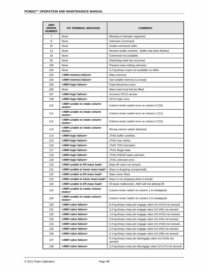
PG9602™ OPERATION AND MAINTENANCE MANUAL
© 2011 Fluke Calibration Page 48
AMH ERROR
NUMBER PG TERMINAL MESSAGE COMMENT
7 None Missing or improper argument.
9 None Unknown Command.
10 None Invalid command suffix.
13 None Receive buffer overflow. Buffer has been flushed.
18 None Command not available.
60 None Watchdog reset has occurred.
100 None Present mass setting unknown.
102 None 6.2 kg binary mass not available on AMH.
103 <AMH memory failure> Mass memory.
104 <AMH memory failure> Non-volatile memory is corrupt.
105 <AMH logic failure> Fatal electronics error.
106 None Mass load must first be lifted.
107 <AMH logic failure> Incorrect CPLD version.
108 <AMH logic failure> CPLD logic error.
110 <AMH unable to rotate column motor> Column motor switch error on column 0 (C0).
111 <AMH unable to rotate column motor> Column motor switch error on column 1 (C1).
112 <AMH unable to rotate column motor> Column motor switch error on column 2 (C2).
113 <AMH unable to rotate column motor> Wrong column switch detected.
114 <AMH logic failure> JTAG buffer overflow.
115 <AMH logic failure> JTAG max retries.
116 <AMH logic failure> JTAG TDO mismatch.
117 <AMH logic failure> JTAG illegal state.
118 <AMH logic failure> JTAG ENDxR state unknown.
119 <AMH logic failure> JTAG unknown error.
120 <AMH unable to lift mass load> Mass lift valve not sensed.
121 <AMH unable to lower mass load> Mass is dropping unexpectedly.
122 <AMH unable to lift mass load> Mass never lifted.
123 <AMH unable to lower mass load> Mass is not dropping when it should.
124 <AMH unable to lift mass load> IR beam malfunction. AMH will not attempt lift
125 <AMH unable to rotate column motor> Column motor switch on column 1 is misaligned.
126 <AMH unable to rotate column motor> Column motor switch on column 2 is misaligned.
130 <AMH valve failure> 6.4 kg binary mass pin engage valve (VLV#14) not sensed.
131 <AMH valve failure> 3.2 kg binary mass pin engage valve (VLV#6) not sensed.
132 <AMH valve failure> 1.6 kg binary mass pin engage valve (VLV#12) not sensed.
133 <AMH valve failure> 0.8 kg binary mass pin engage valve (VLV#4) not sensed.
134 <AMH valve failure> 0.4 kg binary mass pin engage valve (VLV#10) not sensed.
135 <AMH valve failure> 0.2 kg binary mass pin engage valve (VLV#2) not sensed.
136 <AMH valve failure> 0.1 kg binary mass pin engage valve (VLV#8) not sensed.
137 <AMH valve failure> 6.4 kg binary mass pin disengage valve (VLV#15) not sensed.
138 <AMH valve failure> 3.2 kg binary mass pin disengage valve (VLV#7) not sensed.

3. GENERAL OPERATION
Page 49 © 2011 Fluke Calibration
AMH ERROR
NUMBER PG TERMINAL MESSAGE COMMENT
139 <AMH valve failure> 1.6 kg binary mass pin disengage valve (VLV#13) not sensed.
140 <AMH valve failure> 0.8 kg binary mass pin disengage valve (VLV#5) not sensed.
141 <AMH valve failure> 0.4 kg binary mass pin disengage valve (VLV#11) not sensed.
142 <AMH valve failure> 0.2 kg binary mass pin disengage valve (VLV#3) not sensed.
143 <AMH valve failure> 0.1 kg binary mass pin disengage valve (VLV#9) not sensed.
3.8 Main Run Screen The PG9000 main run screen is its home display that is reached upon powering up and from which other functions and menus are accessed. It is the top level of all menu structures.
The main run screen is where PG9000 is left in normal operation. It displays the pressure defined by PG9000, Ready/Not Ready conditions and a variety of other information.
Note The screen described below is called the MAIN run screen. The SYSTEM and AMBIENT screens (see Sections 3.10.5 and 3.10.6) are also run screens in the sense that all the other functions may be accessed directly from them and pressure or mass entries may be made from them. See Section 3.9 for a description of PG9000’s main menu/function structure.
prvPRESSURE1 unit aGh +N.N mm NN.NNNNN kg
1. <prv>: Three Ready/Not Ready indication characters (from left to right: piston position, piston rotation, vacuum reference) (see Section 3.4). Each character indicates as follows: <p>: Piston Position Ready/Not Ready. <*> when Ready, <↑> when Not Ready due to piston above measuring zone, <↓> when Not Ready due to piston below measuring zone, <?> if piston position not available or out of range. Flashes if condition is Not Ready and piston is floating (see Section 3.4.1). Indicates Not Ready when automated pressure generation is adjusting pressure. <r>: Piston Rotation Ready/Not Ready. <*> when Ready, <<> when Not Ready due to piston rotation rate too low or motorized rotation engaged, <?> if piston position not available or out of range. Flashes if condition is Not Ready and piston is floating. (see Section 3.4.2). <v>: Vacuum Reference Ready/Not Ready (if available). <*> when Ready, <v> if Not Ready due to vacuum not below ready limit. Flashes if condition is Not Ready and piston is floating (see Section 3.4.3).
2. <PRESSURE1>: Numerical value and sign of the calculated pressure as defined by PG9000 with current mass loaded on current piston when all Ready/Not Ready indication characters indicate Ready.
3. <unit>: Current pressure unit of measure (see Section 3.10.3).
4. Current measurement mode. <a> for absolute, <g> for gauge, <d> for differential (see Section 3.10.4).
5. Automated pressure generation status. <G> if automated pressure generation is ON. The <G> flashes if automated pressure generation is active, blank if automated pressure generation is not ON (see Section 3.10.9).
6. DUT head correction status. <h> if a head correction is actively being applied, blank if head height is zero (see Section 3.10.7).
7. <NN.NNNNN kg>: Current mass load in true mass (assuming mass loading instructions have been followed and/or mass loading entries are correct (see Section 3.6).
8. <± N.N mm>: Current piston position in millimeters from midstroke position. Positive values are above midstroke, negative values below. Indicates < ---- > if piston position not available or out of range (see Section 3.5).
Note
• When a number is too large to display in the allocated screen space, PG9000 displays <********> or <OVERFLOW>.
• PG9000 has a screen saver function that causes the display to dim if NO key is pressed for 10 minutes. Pressing a key restores full power to the display.
• The screen saver activation time can be changed or screen saving can be completely disabled (see Section 3.12.4.1).

PG9602™ OPERATION AND MAINTENANCE MANUAL
© 2011 Fluke Calibration Page 50
3.9 General Function/Menu Flow Chart Local operator interface with PG9000 is provided by PG Terminal keypad and display. Normal PG9000 operation is organized around run screens from which functions and menus are accessed. The run screens include:
• MAIN run screen: Displays Ready/Not Ready, defined pressure, piston position and mass load. • SYSTEM run screens: Display piston position, rotation, temperature and reference vacuum. • AMBIENT run screen: Displays ambient pressure temperature, relative humidity and local gravity.
Figure 18 outlines the operating protocol of the run screens and associated key presses.
Figure 18. Run Screen Flow Chart
3.10 Direct Function Keys
3.10.1 Direct Function Keys Summary Local operator interface with PG9000 is provided by the PG Terminal keypad and display. To minimize the use of multi-layered menu structures, the keypad’s numerical keys also provide direct access to the most commonly used functions. The function accessed is labeled on the bottom half of the each key. Direct function keys are active whenever PG9000 is in a run screen (MAIN, SYSTEM or AMBIENT). Table 11 summarizes the operation of the direct function keys. Section 3.9 provides a flow chart of PG Terminal general operation. See corresponding manual Sections to 3.10.1 to 3.12.9.
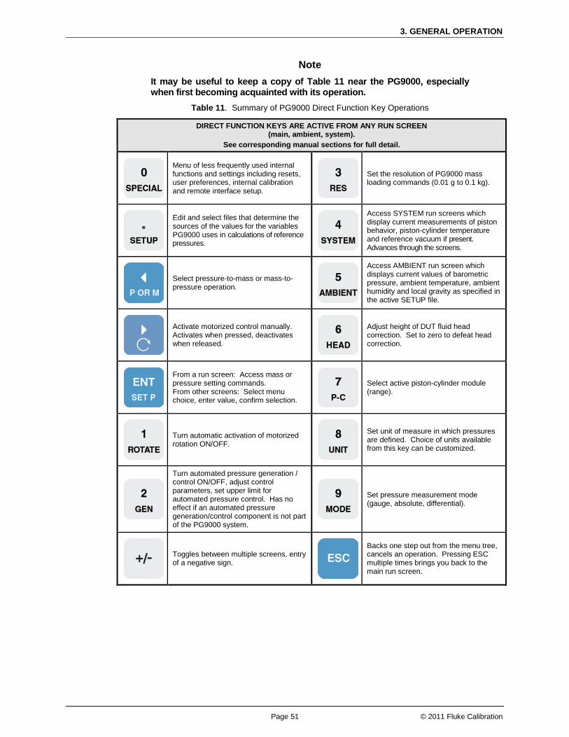
3. GENERAL OPERATION
Page 51 © 2011 Fluke Calibration
Note It may be useful to keep a copy of Table 11 near the PG9000, especially when first becoming acquainted with its operation.
Table 11. Summary of PG9000 Direct Function Key Operations
DIRECT FUNCTION KEYS ARE ACTIVE FROM ANY RUN SCREEN (main, ambient, system).
See corresponding manual sections for full detail.
Menu of less frequently used internal functions and settings including resets, user preferences, internal calibration and remote interface setup.
Set the resolution of PG9000 mass loading commands (0.01 g to 0.1 kg).
Edit and select files that determine the sources of the values for the variables PG9000 uses in calculations of reference pressures.
Access SYSTEM run screens which display current measurements of piston behavior, piston-cylinder temperature and reference vacuum if present. Advances through the screens.
Select pressure-to-mass or mass-to-pressure operation.
Access AMBIENT run screen which displays current values of barometric pressure, ambient temperature, ambient humidity and local gravity as specified in the active SETUP file.
Activate motorized control manually. Activates when pressed, deactivates when released.
Adjust height of DUT fluid head correction. Set to zero to defeat head correction.
From a run screen: Access mass or pressure setting commands. From other screens: Select menu choice, enter value, confirm selection.
Select active piston-cylinder module (range).
Turn automatic activation of motorized rotation ON/OFF.
Set unit of measure in which pressures are defined. Choice of units available from this key can be customized.
Turn automated pressure generation / control ON/OFF, adjust control parameters, set upper limit for automated pressure control. Has no effect if an automated pressure generation/control component is not part of the PG9000 system.
Set pressure measurement mode (gauge, absolute, differential).
Toggles between multiple screens, entry of a negative sign.
Backs one step out from the menu tree, cancels an operation. Pressing ESC multiple times brings you back to the main run screen.
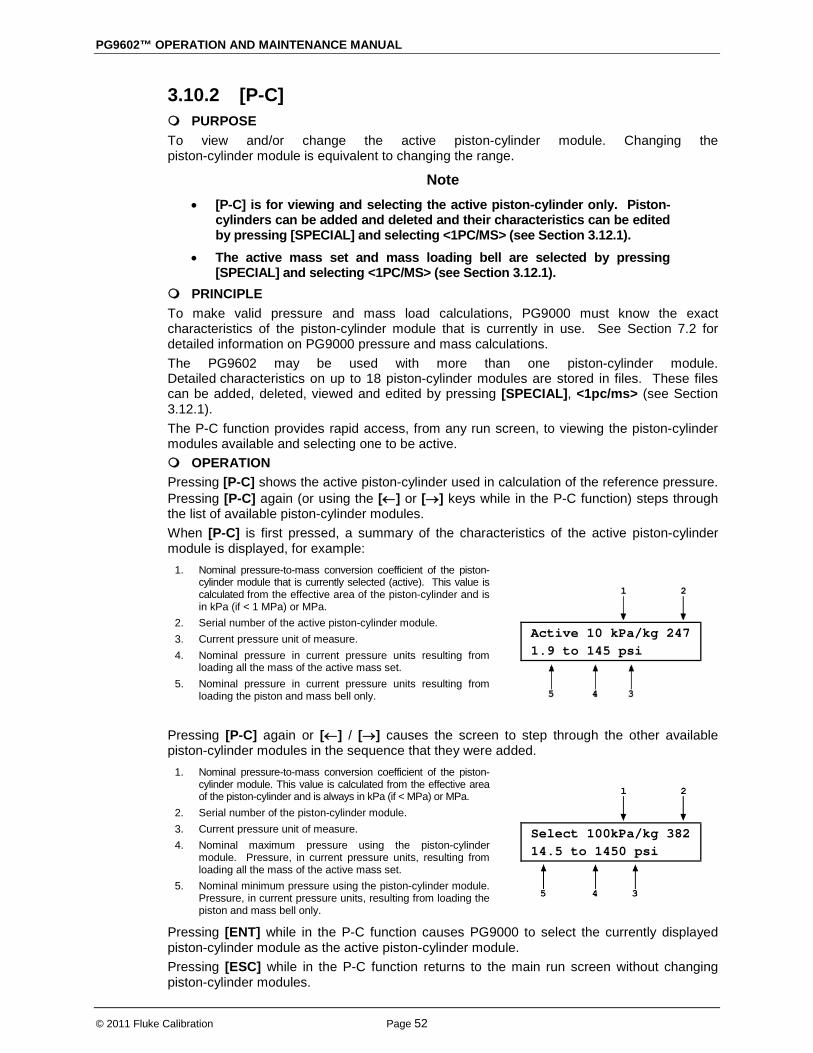
PG9602™ OPERATION AND MAINTENANCE MANUAL
© 2011 Fluke Calibration Page 52
3.10.2 [P-C] PURPOSE To view and/or change the active piston-cylinder module. Changing the piston-cylinder module is equivalent to changing the range.
Note • [P-C] is for viewing and selecting the active piston-cylinder only. Piston-
cylinders can be added and deleted and their characteristics can be edited by pressing [SPECIAL] and selecting <1PC/MS> (see Section 3.12.1).
• The active mass set and mass loading bell are selected by pressing [SPECIAL] and selecting <1PC/MS> (see Section 3.12.1).
PRINCIPLE To make valid pressure and mass load calculations, PG9000 must know the exact characteristics of the piston-cylinder module that is currently in use. See Section 7.2 for detailed information on PG9000 pressure and mass calculations. The PG9602 may be used with more than one piston-cylinder module. Detailed characteristics on up to 18 piston-cylinder modules are stored in files. These files can be added, deleted, viewed and edited by pressing [SPECIAL], <1pc/ms> (see Section 3.12.1). The P-C function provides rapid access, from any run screen, to viewing the piston-cylinder modules available and selecting one to be active. OPERATION Pressing [P-C] shows the active piston-cylinder used in calculation of the reference pressure. Pressing [P-C] again (or using the [←] or [→] keys while in the P-C function) steps through the list of available piston-cylinder modules. When [P-C] is first pressed, a summary of the characteristics of the active piston-cylinder module is displayed, for example:
1. Nominal pressure-to-mass conversion coefficient of the piston-cylinder module that is currently selected (active). This value is calculated from the effective area of the piston-cylinder and is in kPa (if < 1 MPa) or MPa.
2. Serial number of the active piston-cylinder module. 3. Current pressure unit of measure. 4. Nominal pressure in current pressure units resulting from
loading all the mass of the active mass set. 5. Nominal pressure in current pressure units resulting from
loading the piston and mass bell only.
Active 10 kPa/kg 247 1.9 to 145 psi
Pressing [P-C] again or [←] / [→] causes the screen to step through the other available piston-cylinder modules in the sequence that they were added.
1. Nominal pressure-to-mass conversion coefficient of the piston-cylinder module. This value is calculated from the effective area of the piston-cylinder and is always in kPa (if < MPa) or MPa.
2. Serial number of the piston-cylinder module. 3. Current pressure unit of measure. 4. Nominal maximum pressure using the piston-cylinder
module. Pressure, in current pressure units, resulting from loading all the mass of the active mass set.
5. Nominal minimum pressure using the piston-cylinder module. Pressure, in current pressure units, resulting from loading the piston and mass bell only.
Select 100kPa/kg 382 14.5 to 1450 psi
Pressing [ENT] while in the P-C function causes PG9000 to select the currently displayed piston-cylinder module as the active piston-cylinder module. Pressing [ESC] while in the P-C function returns to the main run screen without changing piston-cylinder modules.

3. GENERAL OPERATION
Page 53 © 2011 Fluke Calibration
Note • The pressure unit of measure in which the range offered by the piston-
cylinder module using the active mass set is displayed can be changed by pressing [UNIT] (see Section 3.10.3).
• When the current pressure unit of measure is an altitude unit, piston-cylinder module range is expressed in kPa if the altitude unit is meters (m) or psi if the altitude unit is feet (ft).
3.10.3 [UNIT] PURPOSE To specify the unit of measure in which defined pressures are expressed.
PRINCIPLE PG9000 supports a wide variety of pressure units of measure. Internally, PG9000 always operates in Pascal [Pa] (the SI unit of pressure). Values of pressure are represented in other units by the application of conversion factors to convert from Pascal. See Section 7.1.1 for Unit of Measure Conversions. The pressure unit of measure selection (e.g., psi, kPa, etc.) is separate from the pressure measurement mode selection (gauge, absolute or differential). See Section 3.10.4 for information on changing the measurement mode.
OPERATION
To change the pressure unit of measure, press the [UNIT] function key from any run screen. The display shows six place holders of units. If a desired unit is not displayed, it can be added by the user.
1kPa 2Mpa 3Pa 4bar 5psi 6kcm2
The cursor is on the number corresponding to the active unit. To change the pressure unit, select the desired unit. The display returns to the previous run screen with the selected unit active.
If the pressure unit selected is inWa (Inches of Water column), the reference temperature for water density must be specified. When inWa is selected as the unit, the next display is:
Select inWa ref temp
4°C 20°C 60°F
Select the desired reference temperature for water density using the [←] or [→] key to move the cursor. Pressing [ENT] returns to the main run screen with inWa based on water density at the selected reference temperature as the active pressure unit. The current inWa reference temperature can be viewed by observing the position of the cursor in the reference temperature screen.
Note • See Section 7.1.17.1.1 for tables of the pressure unit of measure
conversion factors used by PG9000. • The UNIT function provides rapid access to a choice of up to six units.
The choice of units can be customized from a wider selection by the user (see Section 3.10.3.1). The default units are:
1kPa 2MPa 3Pa 4bar 5psi 6kcm2 • To restore the default UNIT function settings, use the Unit Reset (see
Section 3.12.9.2). • Certain internal and/or metrological functions (e.g., vacuum reference
pressure) are always represented in Pascal [Pa], regardless of the active pressure unit of measure.
• When the current pressure unit of measure is an altitude unit, atmospheric pressure in the AMBIENT run screen is expressed in kPa if the altitude unit is meters (m) or psi if the altitude unit is feet (ft).

PG9602™ OPERATION AND MAINTENANCE MANUAL
© 2011 Fluke Calibration Page 54
3.10.3.1 Customizing Pressure Units Available Under the UNIT Function
PURPOSE To customize the selection of pressure units that are available for selection from the [UNIT] function key.
PRINCIPLE The UNIT function provides a choice of six different commonly used pressure units of measure. The units that are available by default are those indicated in the Note in Section 3.10.3 above. However, PG9000 supports many other pressure units of measure. Other units can be made available for selection and units can be deleted by customizing the UNIT function. This allows PG9000 to offer a wide selection of units while simplifying day to day operation. The typical user will customize the [UNIT] function key to support the six most commonly used units. If the desired unit of measure is not displayed, then edit the field by accessing the SETUP, <2PresU> menu.
OPERATION To customize the units of measure displayed when pressing [UNIT] function key. From the main run screen press [SETUP] and select <2PresU>. The display is:
1. The UNIT number in the [UNIT] menu that is to be changed.
Set up user unit #6
Enter the number of the unit place holder position that you would like to change. The display becomes:
Unit #6 1SI 2other 3altitude 4user
Select the desired pressure unit category. SI units include units based on SI such as Pa, bar, mmHg. Select the desired unit from the unit list.
Table 12. Pressure Units of Measure Available
<1SI> <2Other> <3altitude>* <4User>** <1Pa> <2Kpa> <3MPa> <4mbar> <5bar> <6mmHg> <7mmWa>
<1psi> <2psf> <3inHg> <4inWa> <5kcm2> <6Torr> <7mTor> <8none>
<1m> <2ft>
<1user>
* <3altitude>: in absolute by vacuum mode only. ** <4user>: User defined unit. .
The UNIT function display is not required to display six units. If there are units of measure that will not be used and it is not desirable to display them as a selection, then they can be deleted from the quick-view UNIT display. To delete the current unit from the UNIT screen and show no unit, select <2other>, <6none> for that unit number.
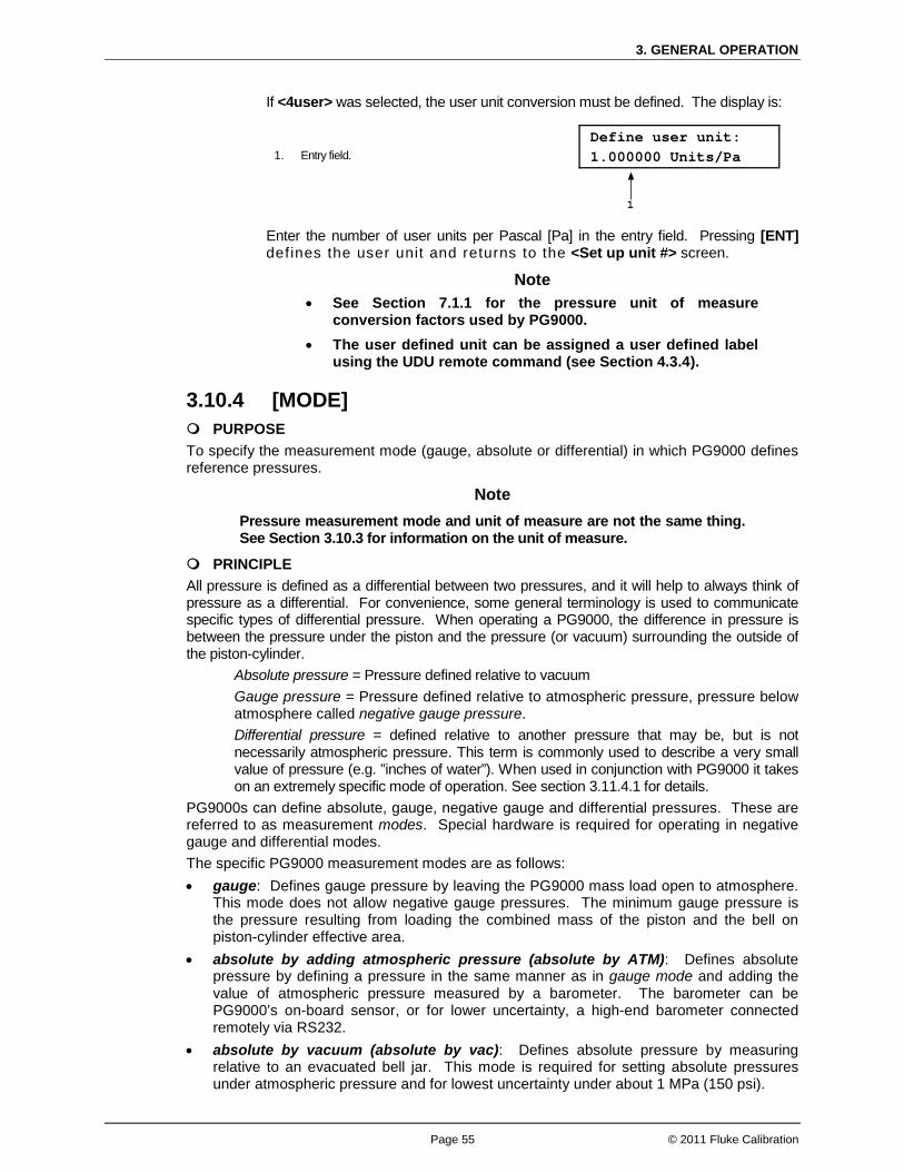
3. GENERAL OPERATION
Page 55 © 2011 Fluke Calibration
If <4user> was selected, the user unit conversion must be defined. The display is:
1. Entry field.
Define user unit: 1.000000 Units/Pa
Enter the number of user units per Pascal [Pa] in the entry field. Pressing [ENT] def ines the user unit and returns to the <Set up unit #> screen.
Note • See Section 7.1.1 for the pressure unit of measure
conversion factors used by PG9000. • The user defined unit can be assigned a user defined label
using the UDU remote command (see Section 4.3.4).
3.10.4 [MODE] PURPOSE To specify the measurement mode (gauge, absolute or differential) in which PG9000 defines reference pressures.
Note Pressure measurement mode and unit of measure are not the same thing. See Section 3.10.3 for information on the unit of measure.
PRINCIPLE All pressure is defined as a differential between two pressures, and it will help to always think of pressure as a differential. For convenience, some general terminology is used to communicate specific types of differential pressure. When operating a PG9000, the difference in pressure is between the pressure under the piston and the pressure (or vacuum) surrounding the outside of the piston-cylinder.
Absolute pressure = Pressure defined relative to vacuum Gauge pressure = Pressure defined relative to atmospheric pressure, pressure below atmosphere called negative gauge pressure. Differential pressure = defined relative to another pressure that may be, but is not necessarily atmospheric pressure. This term is commonly used to describe a very small value of pressure (e.g. ”inches of water”). When used in conjunction with PG9000 it takes on an extremely specific mode of operation. See section 3.11.4.1 for details.
PG9000s can define absolute, gauge, negative gauge and differential pressures. These are referred to as measurement modes. Special hardware is required for operating in negative gauge and differential modes. The specific PG9000 measurement modes are as follows: • gauge: Defines gauge pressure by leaving the PG9000 mass load open to atmosphere.
This mode does not allow negative gauge pressures. The minimum gauge pressure is the pressure resulting from loading the combined mass of the piston and the bell on piston-cylinder effective area.
• absolute by adding atmospheric pressure (absolute by ATM): Defines absolute pressure by defining a pressure in the same manner as in gauge mode and adding the value of atmospheric pressure measured by a barometer. The barometer can be PG9000’s on-board sensor, or for lower uncertainty, a high-end barometer connected remotely via RS232.
• absolute by vacuum (absolute by vac): Defines absolute pressure by measuring relative to an evacuated bell jar. This mode is required for setting absolute pressures under atmospheric pressure and for lowest uncertainty under about 1 MPa (150 psi).

PG9602™ OPERATION AND MAINTENANCE MANUAL
© 2011 Fluke Calibration Page 56
• differential (dif): Defines differential pressures at an absolute static pressure between vacuum and two atmospheres by defining an absolute pressure relative to an evacuated bell jar and subtracting static pressure monitored by a digital pressure indicator. An offsetting technique ensures that only the digital indicator’s resolution and very short term repeatability influence the measurement results. Allows positive and negative differential pressure (including gauge pressures) with one common hardware setup. Covers pressures very near and at zero without limitations due to piston-cylinder size and mass loads (see Section 3.10.4.1).
OPERATION To change the pressure measurement mode, press [MODE] from any run screen. The resulting display depends on the PG9000 Model: The cursor is on the number corresponding to the current measurement mode.
Measurement mode: 1g 2avac 3aatm 4dif
Selecting <2avac> enables absolute by vacuum mode. Selecting <3aatm> enables absolute by ATM mode. Selecting <4dif> enables differential mode. Making a measurement mode selection returns to the previous run screen with the selected mode active.
Note When using an AMH, be sure to apply drive vacuum to the AMH when switching operation to absolute by vacuum mode (see 3.7.2.5).
3.10.4.1 Differential Measurement Mode PURPOSE To define gauge pressures near and under atmospheric pressure that cannot be covered in conventional gauge mode; to define pressures at a static pressure near atmospheric pressure but other than atmospheric pressure.
Note Differential mode operation requires additional hardware and that the PG9000 SETUP selection for AtmP be configured for an external barometer connected to COM2 (see Section 3.11, 3.12.5.4). Differential mode operation also requires the PG9000 Differential Mode Interconnections kit P/N 3070127, which includes the Differential Mode housing.
PRINCIPLE Differential mode is designed to allow PG9000 to define pressures which piston gauges have typically not covered or for which they have been difficult to use. This includes positive and negative gauge pressures near zero, for example ± 2.5 kPa (10 in. H2O); as well as low differential pressures at low absolute static pressures, for example 0 to 2.5 kPa (20 Torr) at 15 kPa absolute (2.2 psia) static pressure. The principal of differential mode is to define a differential pressure as the difference between an absolute pressure relative to vacuum and a second absolute pressure (the static pressure) measured by a precision Reference Pressure Monitor (RPM). An offsetting procedure “tares” the RPM so that the uncertainty contributed to the differential pressure by the RPM’s measurement is a function of the RPM resolution and short term repeatability rather than its absolute accuracy and long term stability. For differential mode operation, the static pressure is set to the desired value as measured by the RPM (atmospheric pressure for gauge pressure measurements). The RPM offset at the static pressure is determined by applying the static pressure as defined by the PG9000 following:
3. GENERAL OPERATION
Page 57 © 2011 Fluke Calibration
RPMoffset = PGRPMstart - RPMindicate Where:
PGRPMstart = Pressure applied by PG9000 to RPM (nominally equal to RPMstart)
RPMindicate = RPM reading when PGRPMstart is applied to RPM test port
Once the RPM offset has been determined, differential pressures are defined by subtracting the static pressure measured by the RPM from an absolute pressure defined by the PG9000 following:
PGdif = PGabs - RPMcurrent - RPMoffset Where:
Pgdif = Differential pressure defined by PG9000 Pgabs = Absolute pressure defined by PG9000 RPMcurrent = Current RPM indication of static pressure RPMoffset = Disagreement between PG9000 and RPM at
the operating static pressure For differential mode operation, the PG9000 Differential Mode Interconnections Kit should be used to provide the DUT high and low test connections and support the RPM offsetting procedure (see Figure 19 and Section 3.10.4.1). A precision Reference Pressure Monitor, such as a Fluke Calibration (DH Instruments) RPM3, should be selected for the AtmP source in SETUP (see Section 3.11, 3.12.5.4). Other RPM models are a good choice, but the sheet metal for the Differential Mode housing is sized for the RPM3. PG9000 differential measurement mode manages the data acquisition, communications, and handling to support differential mode operation without operator effort. Differential mode operation requires setting the static pressure at which differential measurements are to be made and regular determination of the RPM offset. These functions are supported under [MODE], <4dif>.

PG9602™ OPERATION AND MAINTENANCE MANUAL
© 2011 Fluke Calibration Page 58
PG/STATIC P CONTROL Port
PG Port
TEST HIGH Port (Quick Connection)
TEST LOW Port (Quick Connection)
1/8 in. NPT F or 4T Quick Connector
STATIC P Port
STATIC P SUPPLY Port
CONTROL SELECTION Valve
PG SHUTOFF Valve
TEST BYPASS Valve
Reference Pressure Monitor (RPM) (Optional)
STATIC P SELECTION Valve
Static Pressure Exhaust (Internal)
Figure 19. Differential Mode Controller Schematic
Note Fluke Calibration Technical Note 9940TN02 provides detailed information on differential mode principles and includes a complete uncertainty analysis. Consult Fluke Calibration or visit www.flukecal.com.
OPERATION To select differential mode operation and access differential mode functions press [MODE] and select <4dif>. Differential mode operation includes: Selecting differential mode, setting static pressure and finding the RPM offset (see Section 3.10.4.1, Selecting Differential Mode, Setting Static Pressure, Finding RPM Offset (<1run>)Operating in differential mode (see Section
. 3.10.4.1, Operating In
Differential ModeViewing differential mode static pressure and RPM offset (see Section
). 3.10.4.1,
Viewing Static Pressure and RPM Offset (<2view>). Selecting Differential Mode, Setting Static Pressure, Determining RPM Offset (<1run>)

3. GENERAL OPERATION
Page 59 © 2011 Fluke Calibration
Note To operate in differential mode and/or execute the RPM offset determination procedure, the AtmP selection under SETUP must be external (COM2) (see Section 3.11). If this is not the case, an error message will be displayed (<Dif mode requires COM2 AtmP SETUP>) when attempting to activate differential mode.
To select differential mode operation and/or execute the RPM offset determination procedure, press [MODE] and select <4dif>, <1run>. The display is:
1. Current value of RPM offset. Always in Pascal [Pa].
Offset: 9.03 Pa New offset? 1no 2yes
Select <1no> to use the existing RPM offset and return the previous run screen in differential mode (see Section 3.10.4.1, Operating in Differential Mode
Note ).
The RPM offset should be redetermined any time the static pressure value is changed, as well as at the beginning of each calibration or test sequence. If the difference in the value of the RPM offset in subsequent determinations is < 0.1 Pa, then less frequent offset determinations may be considered.
Select <2yes> to proceed with a new determination of the RPM offset. The display is:
1. Current pressure reading of the RPM in the current units of.
Set RPM P & [ENT] 96.57785 kPa a
Table 13. Valve Settings for Setting Differential Mode Static Pressure
VALVE VALVE SETTING
Control Selection Static P
PG Shutoff Closed
Test Bypass Open
Static P Selection Off If static pressure is atmospheric pressure VENT or OFF
With the Differential Mode Controller valves (see Figure 19) set as indicated in Table use the system’s pressure control component to set the desired static pressure value as read by the RPM. If the desired static pressure is atmospheric pressure (for example, for low gauge and negative gauge differential pressures), set the STATIC P SELECTION valve to VENT. If a REFERENCE VOLUME is connected to the STATIC P port and the desired static pressure is less than atmospheric pressure, consider setting the STATIC P SELECTION VALVE to SUPPLY. This will connect the pressure setting vacuum source directly to the reference volume and reduce pull down time.

PG9602™ OPERATION AND MAINTENANCE MANUAL
© 2011 Fluke Calibration Page 60
Caution Be sure the TEST BYPASS valve is in the OPEN position before adjusting the static pressure. Failure to do so will cause differential pressure to be generated across the HIGH and LOW TEST ports which may overpressure the DUT.
When the static pressure, as indicated by the RPM, has been set to the desired value, press [ENT]. PG9000 reads the RPM and calculates the mass to load on PG9000 to set the pressure value indicated by the RPM. The display is:
Load mass & vac: 9.2 kg & 32.47 g
Note When using an AMH, the mass value to set the value indicated by the RPM is always loaded with resolution of 0.1 kg. This is to avoid having to break the reference vacuum to load trim masses. The differential pressure values are loaded with the resolution specified in [RES] (see Section 3.10.10).
This is the standard nominal mass loading in instruction display of pressure-to-mass mode (see Section 3.10.11.1). The mass loading instruction is always given with 0.01 g resolution regardless of the current mass loading resolution setting (see Section 3.10.10). Load the mass value following PG9000 mass loading protocol (see Section 3.6). If an AMH is being used, the mass is loaded automatically and default mass loading resolution of 0.1 kg is used. Set the PG9000 Differential Mode Controller (see Figure 19) to apply the pressure defined by the PG9000 to the RPM (see Table 14).
Table 14. Valve Settings to Apply PG9000 Pressure to the RPM for Differential Mode Offsetting
VALVE VALVE SETTING
Control Selection PG
PG Shutoff Open
Test Bypass Open
Static P Selection Off If static pressure is atmospheric pressure VENT or OFF

3. GENERAL OPERATION
Page 61 © 2011 Fluke Calibration
Once the valves have been properly set and the mass has been loaded, install the bell jar and establish vacuum under the bell jar. Then press [ENT]. The display is:
1. Current pressure reading of the RPM in the current units of measure.
2. Standard main run screen piston position indication (see Section 3.7).
3. Current RPM offset (pressure applied by PG9000 - RPM indication). Indicates ******* if the value is > 9999.99 Pa. Pressure unit of measure is always Pascal [Pa].
<<* 99.9785 kPa a h -3.5 Off: -7.89 Pa
Float and rotate the PG9000 piston-cylinder. When the PG9000 is Ready (see Section 3.4), press [ENT]. Wait about 6 seconds while the PG9000 samples and averages multiple readings. The display is:
1. RPM offset currently in use. 2. New RPM offset just measured.
Old offset: -7.72 Pa New offset: -7.89 Pa
To record the new RPM offset and go to the previous run screen in differential mode with the new RPM offset active, press [ENT]. To return to the <New offset?> screen, press [ESC]. See Section 3.10.4.1, Operating in Differential Mode
Note
, for information on differential mode operation.
• The value of the RPM offset typically should be inside of ± 20 Pa. An RPM offset value outside of this range may indicate a poorly calibrated RPM or a problem with the offset determination procedure.
• The difference between the RPM offset at the beginning and at the end of a test will be reflected as zero drift of the differential pressures defined during the test. To quantify this value, perform the RPM offset procedure at the beginning and at the end of a test and evaluate the difference between the starting and ending RPM offset values.
Caution Operating in Differential Mode
Differential mode is often used to calibrate DUTs with very low differential pressure ranges. These can easily be over pressured and damaged by inadvertently applying excessive pressure to one port. OPEN the TEST BYPASS valve to zero the differential across the DUT when there is a risk of overpressure.
Once the offset determination process is completed, operating in differential mode is nearly identical to operating in absolute by vacuum mode (see Section 3.10.11). Unless an AMH is used, vacuum under the bell jar must be vented to make mass load changes and reestablished to set a pressure.

PG9602™ OPERATION AND MAINTENANCE MANUAL
© 2011 Fluke Calibration Page 62
Operation is in either pressure-to-mass or mass-to-pressure mode (see Section 3.10.12). To operate in differential mode, set the PG9000 Differential Mode Controller (see Figure 19) to apply pressure defined by PG9000 to the high side of the DUT.
Table 15. Valve Settings for Operating in Differential Mode
VALVE VALVE SETTING
Control Selection To adjust pressure under PG9000 piston-cylinder PG To adjust static pressure: STATIC P
PG Shutoff Piston is floating or near floating: OPEN Any other time: CLOSED
Test Bypass To make differential pressure measurements: CLOSED To set or check DUT zero: OPEN
Static P Selection OFF If static pressure is atmospheric pressure: VENT or OFF
Note For the highest quality differential mode measurements, use consistent conditions for static pressure and PG9000 vacuum reference pressure at each point. Set the PG9000 Differential Mode Interconnections Kit CONTROL valve to STATIC P to readjust the static pressure to the same value at each point if necessary. This value should be the same as the value at which the RPM offset was determined.
See Typical Differential Mode Operational Sequence
Figure 19 for a schematic of the Differential Mode Controller and its valves.
Set RPM offset at desired static pressure (see Section 3.10.4.1, Selecting Differential Mode, Setting Static Pressure, Finding RPM Offset (<1run>)).
Select pressure-to-mass or mass-to-pressure mode (see Section 3.10.12).
Put the Differential Mode Controller PG SHUTOFF valve in CLOSED position.
If desired, read DUT output at zero differential pressure with TEST BYPASS valve open. Put TEST BYPASS valve in CLOSED position. If desired, put CONTROL valve in STATIC P position and use system control component to adjust static pressure to starting value.
Press [ENT] and enter a pressure or mass value. Load mass as instructed on PG9000.
Install the bell jar on PG9000, shut the PG9000 vacuum vent valve, open vacuum reference shutoff valve. Wait for vacuum under bell jar to reach Ready condition. If using AMH automated mass handler and mass loading resolution of 0.1kg, mass can be changed without breaking vacuum.
Put CONTROL valve in PG position and use system control component to float PG9000 piston. Slowly put PG SHUTOFF valve into OPEN position. Readjust pressure to float the PG9000 piston-cylinder if necessary.
If desired, put CONTROL valve in STATIC P position and use system control component to adjust static pressure to starting value.
When PG9000 indicates Ready on all Ready/Not Ready indicators, take DUT reading at differential pressure indicated on the top line of the PG9000 display.
Slowly put PG SHUTOFF valve in CLOSED position.

3. GENERAL OPERATION
Page 63 © 2011 Fluke Calibration
Shut vacuum reference shutoff valve, open vacuum vent valve. Wait for pressure under bell jar to return to ambient. Remove bell jar. This step is not necessary is using AMH automated mass handler and mass loading resolution of 0.1 kg.
Repeat Steps through for each desired differential pressure point.
See Setting Zero Differential Pressure
Figure 19 for a schematic of the Differential Mode Controller and its valves. Zero differential pressure can be set by PG9000 or simply by setting the Differential Mode Controller TEST BYPASS valve to the OPEN position which connects the HIGH and LOW TEST ports together. The TEST BYPASS valve OPEN position is a “true” zero. The zero differential pressure value set by PG9000 has the same uncertainty as any other differential pressure point (see Section 1.2.4). Comparing the DUT reading at zero set by TEST BYPASS in the OPEN position and at zero set by PG9000 in differential mode like any other differential pressure, can help quantify the quality of the current RPM offset value. If the difference between the two zero readings is excessive, the RPM offset value should be redetermined (see Section 3.10.4.1, Selecting Differential Mode, Setting Static Pressure, Finding RPM Offset (<1run>)). Also, consider correcting all the DUT readings by the difference in the zero reading found in the two different conditions to correct for the defect in the RPM offset.
To view the current RPM offset and the static pressure value at which the offset was recorded, press [MODE] and select <4dif>, <2view>. This display is:
Viewing Static Pressure and RPM Offset (<2view>)
1. RPM offset value that is currently active. 2. PG9000 pressure at which RPM offset was
recorded.
Offset: -6.33 Pa @99.8755 kPa a
Press [ESC] to return to the <Differential mode:> menu. Press [ENT] to return to the previous run screen.
3.10.5 [SYSTEM] PURPOSE To access the two SYSTEM run screens which display current values of PG9000 piston behavior, piston-cylinder temperature and vacuum reference measurements.
OPERATION To access the SYSTEM run screens, press [SYSTEM]. There are three SYSTEM run screens. Pressing [SYSTEM] or [±] when in a SYSTEM screen cycles through the SYSTEM screens. See the following sections 3.10.5.1 through 3.10.5.3 for detailed information on the contents of the SYSTEM run screens.
Note The SYSTEM screens are run screens. This means that other functions can be accessed from the SYSTEM screens and the active SYSTEM screen will be returned to when leaving functions. The MAIN screen and AMBIENT screen are also run screens (see Section 3.9).

PG9602™ OPERATION AND MAINTENANCE MANUAL
© 2011 Fluke Calibration Page 64
3.10.5.1 First System Run Screen OPERATION The first SYSTEM run screen provides real time display of piston rotation rate, decay in piston rotation rate, piston position and piston fall rate. To access the first SYSTEM run screen, press [SYSTEM] from any run screen. The first SYSTEM run screen displays:
1. <nnn rpm>: Numerical value of current piston rate of rotation. The unit of measure is rotations per minute [rpm] and cannot be changed. Flashes when Not Ready and piston is floating (see Section 3.4.2). Indicates < ---- > when information is unavailable or out of range.
2. <±nn/min>: Numerical value of current decay in piston rotation rate (deceleration). The unit of measure is rotations per minute [rpm/min] and cannot be changed. < ---- > when information is unavailable or out of range.
nnn rpm ±nn/min ±n.nn mm ±n.nn/min
3. <±n.nn/min>: Sign and numerical value of current piston vertical rate of displacement. A negative value indicates piston falling. A positive value indicates piston rising. The unit of measure is millimeters per minute [mm/min] and cannot be changed. Indicates < ---- > when information is unavailable or out of range.
4. <±n.nn mm>: Sign and numerical value of current position of the piston within the piston stroke (see Section 3.5). The unit of measure is millimeters [mm] away from mid-stroke position and cannot be changed. Indicates <HSTOP> when the piston is at the high stop (all the way up) and <LSTOP> when the piston is at the low stop (all the way down). Flashes when Not Ready and piston is floating (see Section 3.4.1). Indicates < ---- > when information is unavailable or out of range.
Pressing [ESC] in the first SYSTEM run screen returns operation to the MAIN run screen. Pressing [SYSTEM] or [±] advances to the second run screen. Pressing [SYSTEM] or [±] again, advances to the third SYSTEM run screen. All function keys are active from the first SYSTEM run screen and operation returns to that screen when leaving functions they were accessed from it.
Note • The measurement systems for piston behavior indications
rely on movement of the mass loading bell. Piston behavior indications (piston position, piston rotation rate) are invalid when the mass bell is not loaded on the piston.
• See Section 3.5 for information on the piston stroke and measurement zone.
3.10.5.2 Second System Run Screen OPERATION The second SYSTEM run screen displays the values of piston-cylinder temperature and temperature rate of change measured by PG9000. The second line of the PG9000 displays the value of the reference vacuum and vacuum rate of change if present. If an optional external vacuum reference measurement is present (see Sections 3.11 and 3.12.5.5), the second SYSTEM run screen provides a real time display of the values measured. To access the second SYSTEM run screen, press [SYSTEM] or [±] from the first SYSTEM run screen. To access the first SYSTEM run screen, press [SYSTEM] from any run screen (see Figure 18).
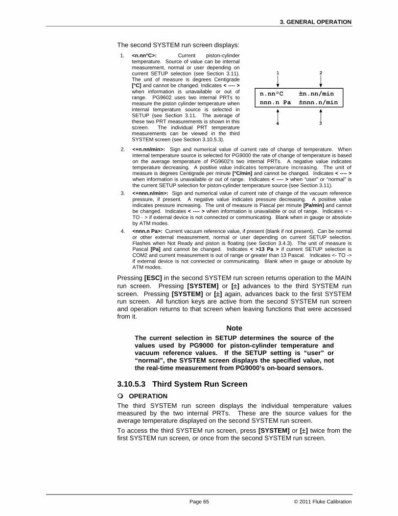
3. GENERAL OPERATION
Page 65 © 2011 Fluke Calibration
The second SYSTEM run screen displays: 1. <n.nn°C>: Current piston-cylinder
temperature. Source of value can be internal measurement, normal or user depending on current SETUP selection (see Section 3.11). The unit of measure is degrees Centigrade [°C] and cannot be changed. Indicates < ---- > when information is unavailable or out of range. PG9602 uses two internal PRTs to measure the piston cylinder temperature when internal temperature source is selected in SETUP (see Section 3.11. The average of these two PRT measurements is shown in this screen. The individual PRT temperature measurements can be viewed in the third SYSTEM screen (see Section 3.10.5.3).
n.nn°C ±n.nn/min nnn.n Pa ±nnn.n/min
2. <+n.nn/min>: Sign and numerical value of current rate of change of temperature. When internal temperature source is selected for PG9000 the rate of change of temperature is based on the average temperature of PG9602’s two internal PRTs. A negative value indicates temperature decreasing. A positive value indicates temperature increasing. The unit of measure is degrees Centigrade per minute [°C/min] and cannot be changed. Indicates < ---- > when information is unavailable or out of range. Indicates < ---- > when “user” or “normal” is the current SETUP selection for piston-cylinder temperature source (see Section 3.11).
3. <+nnn.n/min>: Sign and numerical value of current rate of change of the vacuum reference pressure, if present. A negative value indicates pressure decreasing. A positive value indicates pressure increasing. The unit of measure is Pascal per minute [Pa/min] and cannot be changed. Indicates < ---- > when information is unavailable or out of range. Indicates < - TO - > if external device is not connected or communicating. Blank when in gauge or absolute by ATM modes.
4. <nnn.n Pa>: Current vacuum reference value, if present (blank if not present). Can be normal or other external measurement, normal or user depending on current SETUP selection. Flashes when Not Ready and piston is floating (see Section 3.4.3). The unit of measure is Pascal [Pa] and cannot be changed. Indicates < >13 Pa > if current SETUP selection is COM2 and current measurement is out of range or greater than 13 Pascal. Indicates <- TO -> if external device is not connected or communicating. Blank when in gauge or absolute by ATM modes.
Pressing [ESC] in the second SYSTEM run screen returns operation to the MAIN run screen. Pressing [SYSTEM] or [±] advances to the third SYSTEM run screen. Pressing [SYSTEM] or [±] again, advances back to the first SYSTEM run screen. All function keys are active from the second SYSTEM run screen and operation returns to that screen when leaving functions that were accessed from it.
Note The current selection in SETUP determines the source of the values used by PG9000 for piston-cylinder temperature and vacuum reference values. If the SETUP setting is “user” or “normal”, the SYSTEM screen displays the specified value, not the real-time measurement from PG9000’s on-board sensors.
3.10.5.3 Third System Run Screen OPERATION The third SYSTEM run screen displays the individual temperature values measured by the two internal PRTs. These are the source values for the average temperature displayed on the second SYSTEM run screen. To access the third SYSTEM run screen, press [SYSTEM] or [±] twice from the first SYSTEM run screen, or once from the second SYSTEM run screen.
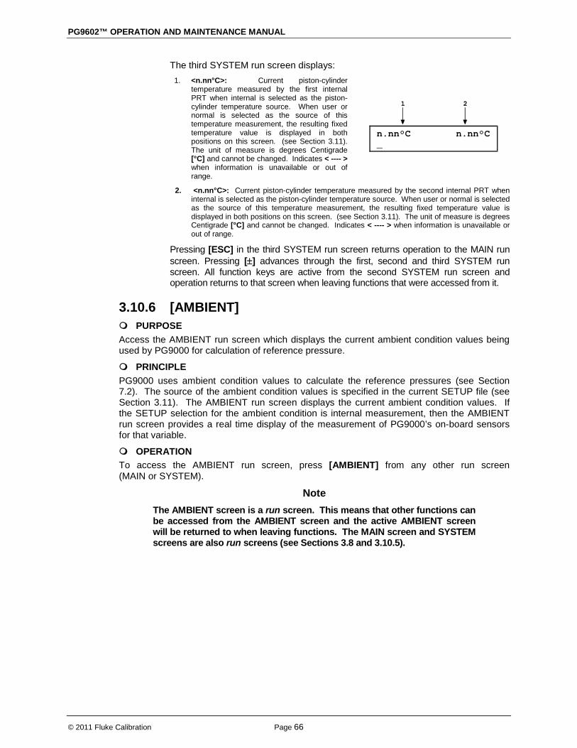
PG9602™ OPERATION AND MAINTENANCE MANUAL
© 2011 Fluke Calibration Page 66
The third SYSTEM run screen displays: 1. <n.nn°C>: Current piston-cylinder
temperature measured by the first internal PRT when internal is selected as the piston-cylinder temperature source. When user or normal is selected as the source of this temperature measurement, the resulting fixed temperature value is displayed in both positions on this screen. (see Section 3.11). The unit of measure is degrees Centigrade [°C] and cannot be changed. Indicates < ---- > when information is unavailable or out of range.
n.nn°C n.nn°C _
2. <n.nn°C>: Current piston-cylinder temperature measured by the second internal PRT when internal is selected as the piston-cylinder temperature source. When user or normal is selected as the source of this temperature measurement, the resulting fixed temperature value is displayed in both positions on this screen. (see Section 3.11). The unit of measure is degrees Centigrade [°C] and cannot be changed. Indicates < ---- > when information is unavailable or out of range.
Pressing [ESC] in the third SYSTEM run screen returns operation to the MAIN run screen. Pressing [±] advances through the first, second and third SYSTEM run screen. All function keys are active from the second SYSTEM run screen and operation returns to that screen when leaving functions that were accessed from it.
3.10.6 [AMBIENT] PURPOSE Access the AMBIENT run screen which displays the current ambient condition values being used by PG9000 for calculation of reference pressure.
PRINCIPLE PG9000 uses ambient condition values to calculate the reference pressures (see Section 7.2). The source of the ambient condition values is specified in the current SETUP file (see Section 3.11). The AMBIENT run screen displays the current ambient condition values. If the SETUP selection for the ambient condition is internal measurement, then the AMBIENT run screen provides a real time display of the measurement of PG9000’s on-board sensors for that variable.
OPERATION To access the AMBIENT run screen, press [AMBIENT] from any other run screen (MAIN or SYSTEM).
Note The AMBIENT screen is a run screen. This means that other functions can be accessed from the AMBIENT screen and the active AMBIENT screen will be returned to when leaving functions. The MAIN screen and SYSTEM screens are also run screens (see Sections 3.8 and 3.10.5).

3. GENERAL OPERATION
Page 67 © 2011 Fluke Calibration
The AMBIENT run screen displays: 1. <nnnnnnn uuuu>: Current numerical value and pressure
unit of atmospheric pressure. Source of value can be internal measurement, remote barometer, normal or user depending on current SETUP selection (see Section 3.11). The unit of measure is determined by the UNIT function setting (see Section 3.10.3). ATM head is applied to internal or external barometer reading to correct atmospheric pressure to the PG9000 reference level (see Section 3.12.3). Indicates < ---- > when information is unavailable or out of range. Indicates <TIMEOUT> if the current SETUP selection is a remote barometer and PG9000 communication with the barometer times out.
nnnnnnn uuuu nn.n°C nn%RH n.nnnnnn/s2
2. <n.nn°C>: Current ambient temperature. Source of value can be internal measurement, normal or user depending on current SETUP selection. The unit of measure is degrees Centigrade [ºC] and cannot be changed. Indicates < ---- > when information is unavailable or out of range.
3. <n.nnnnnnm/s2>: Value of local acceleration due to gravity. Can be normal or user depending on current SETUP selection. The unit of measure is meters per second squared (m/s2) and cannot be changed.
4. <nn%RH>: Current ambient relative humidity. Can be internal measurement, normal or user depending on current SETUP selection (see Section 3.11). The unit of measure is percent relative humidity (%RH) and cannot be changed. Indicates < -- > if current SETUP selection is internal and current measurement is unavailable or out of range.
Pressing [ESC] in the AMBIENT run screen returns operation to the MAIN run screen. All function keys are active from the AMBIENT run screen and operation returns to that screen when leaving functions that were accessed from it.
Note • The current selection in SETUP determines the source of the values used
by PG9000 for atmospheric pressure, ambient temperature and relative humidity. If the SETUP setting is “user” or “normal”, the AMBIENT screen displays the specified value, not the real-time measurement from PG9000’s on-board sensors.
• To change the ambient pressure units of measure, see Section 3.10.3. When the current pressure unit of measure is an altitude unit, atmospheric pressure in the AMBIENT run screen is expressed in kPa if the altitude unit is meters (m) or psi if the altitude unit is feet (ft).
3.10.7 [HEAD] PURPOSE To make a fluid head pressure correction for the height difference between the PG9000 and a DUT.
PRINCIPLE Calculation of the fluid head requires determination of the difference in height between the PG9000 reference level and the level of the DUT. The PG9000 reference level takes into consideration the piston-cylinder natural reference level, geometry and position. The natural reference level of a piston-cylinder is defined as the height at which changes in fluid density have no effect on the defined pressure. For a solid floating piston the natural reference level is located at the bottom of the piston. For hollow pistons (i.e. model PC-7100/7600-10) the geometry is irregular and the natural reference level is located above the bottom of the piston. In order to create a convenient, single location for reference level determination the PG9000 defines the reference level as the location of solid pistons at mid stroke. The calculated reference level offset (a variable that is associated with the piston-cylinder metrological data file) of hollow pistons normalizes the different natural reference levels to the same height, for convenience – the position of a solid piston at mid stroke or reference level (see Figure 20). In this way the DUT height does not need to be determined for each piston-cylinder that is used.

PG9602™ OPERATION AND MAINTENANCE MANUAL
© 2011 Fluke Calibration Page 68
Note • See Section 7.2.2 for information on calculation of the three fluid head
correction functions. • It is important to account for the DUT head, reference level offset and
piston position if performing pressure calculations independently of the PG9000 platform (see Section 7.2.2 for PG9000 fluid head calculations).
• Relative to the mid stroke position, the piston position is automatically corrected in the piston head calculation feature which can be turned ON or OFF (see Section 3.12.3.4).
The pressure defined by a PG9000 floating piston is the pressure at the PG9000 reference level. The reference level is shown in Figure 20 for PG9000 platforms. Frequently, when performing a calibration or test, the device under test is at a different height than the PG9000 reference level. This difference in height (referred to as DUT head) has the potential to cause a significant difference between the pressure defined by the PG9000 at its reference level and the pressure actually applied to the device under test located at a different height. In this case, it is useful to make a head correction to the pressure defined by the PG9000 at its reference level in order to accurately predict the pressure applied at a different height. The HEAD function allows this head correction to be applied automatically for a variety of fluids based on operator entry of the height difference. The fluid used and the HEAD function units of measure are set by pressing [SPECIAL] and selecting <3head> (see Section 3.12.3).
Figure 20. PG9000 Platform Reference Level Location
PG9000 can accurately determine head pressures for nitrogen, helium and air as the pressurized medium. OPERATION To access the HEAD function, press [HEAD]. The display is:
1. Test fluid currently specified for the head correction. 2. Entry field for head height (-999 to 999 cm or in.).
Edit DUT head height 95 cm N2
Entering a value of zero turns the HEAD function OFF. Entering a value other than zero turns the HEAD function ON using the height entered. Pressing [ESC] returns to the main run screen with NO change to the current head setting.

3. GENERAL OPERATION
Page 69 © 2011 Fluke Calibration
Note • The DUT head height should be entered as a positive value if the device or
system under test is above the PG9000 reference level and negative if it is below (see Figure 20).
• The reference level is indicated by a marking on the mounting post or may be determined as a distance of 16.4 mm from the lip of the platform baseplate (see Figure 20).
• To change units of DUT head height between inches and centimeters and to change the test fluid, press [SPECIAL] and select <3Head> (see Section 3.12.3).
• When the HEAD function is ON the application of a head correction is indicated by <h> in the right side of the top line of the MAIN run screen (see Section 3.8). When the HEAD function is OFF, the <h> is NOT shown. PG9000’s also have a separate head correction to compensate for the deviation between the current piston position and mid-stroke (see Section 3.12.3.4). This PISTON head can be turned ON and OFF.
3.10.8 [ROTATE] PURPOSE To turn automatic control of motorized piston rotation (acceleration and brake) ON and OFF.
Note See Section 3.10.13 for information on manual control of motorized piston rotation.
PRINCIPLE The motorized piston rotation system is used to start or increase piston rotation when the piston is floating. It is also used to stop piston rotation when necessary, for example before manipulating mass to set a new pressure. The system operates on an as-needed basis – it engages only when required to bring the rotation rate up to speed, and then it disengages allowing the piston to freely rotate. It rotates the piston by engaging a motor driven belt around the bottom of the mass loading bell to accelerate or brake the rotation rate of the mass bell and piston. The motorized rotation system can engage with the piston at any position in its stroke and at any rotation speed with minimal impact on piston position and the defined pressure. When the motorized rotation system disengages, the piston is completely free. With automatic motorized rotation ON, the motorized rotation system engages and disengages automatically as needed when the piston is floating to maintain the piston rotation rate above the minimum rate Ready limit (see Section 3.4.2). The rotation rate is measured by PG9000 on board sensors and the rotation rate limits are set in the file of the active piston cylinder (see Section 3.12.1.1). Whenever the piston is floating, the motorized rotation system will attempt to maintain the piston rotation rate within the Ready limits (except under the cutoff mass load of 3 kg, at which the low limit is reduced to minimum to maximize free rotation time. The piston rotation Ready/Not Ready indication character indicates Not Ready to alert the operator when the motorized rotation system is about to engage. The rotation system will not engage when the current mass load is less than the mass of the piston + mass loading bell. The motorized rotation system is also used to brake and stop rotation when starting a new pressure point. If the piston is floating and rotating when [ENT/SET P] is pressed, the motorized rotation system engages at a speed near the rotation rate of the piston and then brakes it to a stop. Piston rotation is stopped to avoid loading and unloading masses on the rotating piston and to avoid stopping rotation by friction between the piston and the piston end of stroke stops.

PG9602™ OPERATION AND MAINTENANCE MANUAL
© 2011 Fluke Calibration Page 70
With automatic motorized rotation OFF, the motorized rotation system engages only when actuated by the operator. Pressing [ ] accelerates rotation or [ ] followed by [←] stops rotation (see Section 3.10.13). Automatic motorized rotation is generally left ON for normal operation. It is turned OFF in situations where rotation system actuation independent of operator initiative is undesired (e.g. when performing a crossfloat intercomparison with another piston gauge).
OPERATION
To access the AutoRotate functions, press [ROTATE]. The display is:
AutoRotate OFF 1on 2pre-decel
<AutoRotate ON> or <AutoRotate OFF> indicates the current state of AutoRotate. Use <1on> or <1off> to change the state. When automated rotation is OFF, the PG9000 motorized rotation system will only engage if the operator presses [ ] or [ ] followed by [←] (see Section 3.10.13). When automated rotation is ON, the automated rotation system engages automatically. When the piston is floating, it engages as needed to maintain the piston rotation rate above the Ready limit (see Section 3.4.2). When [ENTER/SET P] is pressed, it engages to stop rotation before masses are loaded and/or the pressure is adjusted (this function can be turned ON and OFF, see Section 3.10.8.1). Manual control using [ ] and [ ] followed by [←] is also still active.
Note • Automatic motorized piston rotation is dependent on PG9000’s
measurements of piston position and rotation rate. These measurements are only available when the mass loading bell is installed on the piston. Automatic piston rotation is suspended when the current PG9000 mass load does not include the mass loading bell.
• Proper operation of the rotation system is dependent on PG9000’s measurements of piston position. When using AutoGen, be sure that the piston position indication system is properly adjusted (see Section 5.2.2).
• When PG9000 is operating in absolute by vacuum mode using the internal vacuum sensor to measure reference vacuum, automatic motorized piston rotation will not engage until the reference vacuum value is within the Ready limit (see Section 3.4.3).
3.10.8.1 <2Pre-Decel> PURPOSE To turn ON and OFF a function that causes the automated rotation system to begin the piston rotation deceleration when [ENT/SET P] is pressed rather than at the time mass is to be loaded. On a PG9000 Platform equipped with motorized rotation, when AutoRotate is on, the piston rotation deceleration function is used to stop rotation before masses are loaded or pressure is adjusted. For larger mass loads, the deceleration function can take up to one minute to execute. Deceleration can therefore be initiated the moment that [ENT/SET P] is pressed to enter a new pressure or mass target. The deceleration function then runs while the new target value is being entered. However, when the next target does not require changing main masses, it may not be necessary to stop piston rotation. In these cases, running the deceleration function is probably not desired and it is not beneficial for piston deceleration to initiate when [ENT/SET P] is pressed. For this reason, the function to start piston deceleration when [ENT/SET P] is pressed can be turned ON or OFF. If pre-deceleration is ON and AutoRotate is ON, then piston rotation deceleration always initiates immediately when [ENT/SET P] is pressed.
3. GENERAL OPERATION
Page 71 © 2011 Fluke Calibration
If pre-deceleration is OFF and AutoRotate is ON, then piston rotation deceleration occurs after entry of the pressure or mass target value and only if the new target requires changing of the main masses with a manual mass set, or operation of the AMH if an automated mass handling system is active.
OPERATION To turn ON and OFF the function that causes stopping of the piston rotation to initiate when [ENT/SET P] is pressed, press [ROTATE], <2pre-decel>. The cursor is on the choice corresponding to the current state. Select <2on> for piston rotation deceleration to initiate when [ENT/SET P] is pressed. Select <1off> for deceleration to initiate only after entry of a new pressure or mass target and only if the main masses need to be moved, or if the AMH needs to be operated. The default is <2on>.
3.10.9 [GEN] PURPOSE To turn ON and OFF automated pressure generation / control, and to view and edit the automated pressure control settings. Requires that an automated pressure generation / control component (such as a PPC4) be included in the PG9000 system and properly configured (see Section 2.4.11).
PRINCIPLE PG9000s support automated pressure generation / control components. These components, when properly configured and interfaced with the PG9000 platform, are controlled by the PG9000 platform to automatically set and adjust pressure to float the piston. Automated pressure generation and control components are interfaced with the PG9000 platform via the COM3 RS232 port (see Section 3.12.5.1). Once an automated pressure generation/control component has been configured and interfaced with the PG9000 platform, the functions under [GEN] are used to turn automated pressure generation/control ON or OFF and to set operating parameters associated with automated pressure control. With automated pressure generation/control ON, PG9000 uses the automated control component to float and refloat the piston when a pressure or mass value is entered. [SET P / ENT] is pressed to initiate a new set command. The automated control function is suspended when any function key is pressed, when entering remote mode or if automated pressure control is turned OFF. After a target pressure or target mass has been entered (locally or remotely) and the required mass has been loaded, the GEN function controls the pressure control component to float the PG9000 piston to the piston float target (see Section 3.10.9.1) and refloat it when necessary. If the piston moves beyond the high or low piston position Ready limit the GEN function refloats it to the piston float target. The piston float target and piston position ready limits are user adjustable (see Section 3.11.2 and 3.11.3 <6READY>). See Section 3.5, Figure 14 for a description of the piston position stroke zones and limits. With automated pressure generation/control OFF, PG9000 leaves the automated pressure generation/control component idle and does not attempt to use it. If an automated pressure control component is included in the PG9000 system, automated pressure generation/control is generally left ON for normal operation. It is turned OFF in situations where pressure control independent of operator initiative is undesired (e.g. when performing a crossfloat intercomparison with another piston gauge). The [GEN] menu includes:
1. Turning the GEN function ON and OFF. 2. The adjustable piston float target that defines the position to which the piston is set
when floated (see Section 3.10.9.1). (e.g. how far above mid float must the piston be before the float process is considered completed)
3. A choice to have the piston raised to the top of the stroke before manipulating mass using an AMH (see Section 3.10.9.2).

PG9602™ OPERATION AND MAINTENANCE MANUAL
© 2011 Fluke Calibration Page 72
4. Viewing and setting the UPPER LIMIT of the automated pressure generation component to avoid accidental overpressure (see Section 3.10.9.3).
5. Viewing and setting the assumed pressure controller tolerance used to determine pressure setting limits when floating the PG9000 piston (see Section 3.10.9.4).
6. A choice to not readjust piston position if the piston is already floating within the Ready position limit after a new target is executed (see Section 3.10.9.5).
OPERATION
To access the GEN functions, press [GEN]. The display is:
AutoGen OFF 1on 2target 3raise 4UL 5tol 6refloat
<AutoGen ON> or <AutoGen OFF> indicates the current state of AutoGen. Use <1on> or <1off> to change the state. If automated pressure control is OFF, PG9000 attempts to turn automated pressure control ON when <1on> is pressed. To do so, communication must be established with a valid automated pressure control component over the COM3 RS232 port (see Section 3.12.5.1). If PG9000 is not able to establish communication with the pressure control component, <P control timeout, autogen off> is displayed momentarily. Correct the communications error with the pressure control component and try again. If PG9000 is able to establish communications with a valid automated pressure control component, <Turning ON automated generation> is displayed momentarily and automated control is turned ON. The PG9000 automated control function will attempt to float the piston within the piston position ready limits (see Section 3.4.1) after any mass-to-pressure or pressure-to-mass command has been confirmed. It will continue to attempt to float the piston until [ENT] is pressed to initiate a new command, a function key is pushed to interrupt AutoGen, or automated pressure control is turned OFF using [GEN]. If automated pressure control is ON and <1off> is pressed, <Turning OFF automated generation> is displayed momentarily and automated control is turned OFF. The PG9000 automated control function is inactive.
Note • Automated pressure generation/control ON is indicated by a <G> in the
right of the top line of the PG Terminal main run screen. The <G> flashes when automated generation is active (see Section 3.8).
• If <G> does not flash after a new pressure target has been executed then it indicates a fault. Turn off AutoGen and turn it back on to reinitialize communication with the automated pressure generation / control device.
• Proper operation of the automated pressure generation/control function is dependent on PG9000’s measurements of piston position. When using AutoGen, be sure that the piston position indication system is properly adjusted (see Section 5.2.2).
• Proper operation of the automated pressure generation/control function is dependent on PG9000’s measurements of piston position and rotation rate. These measurements are only available when the mass loading bell is installed on the piston. Automated pressure generation/control is automatically turned off when the PG9000 entered pressure or mass load does not include the mass loading bell.
Caution To help protect against accidental overpressure, when using automated pressure generation/control, set the upper limit (UL) of the pressure control system using [GEN], <4UL> (see Section 3.10.9.3).

3. GENERAL OPERATION
Page 73 © 2011 Fluke Calibration
3.10.9.1 <2target> PURPOSE To adjust the distance from midstroke to which the piston position must be set before the automated generation system considers the piston floating process complete (see Sections 3.10.9, 3.5).
OPERATION To adjust the AutoGen piston float target press [GEN], <2target>. Edit the value of the target as desired. The default is + 1 mm. The entry should not exceed + 2.5 mm.
3.10.9.2 <3raise> PURPOSE To turn ON and OFF a function that causes the automated generation component to raise the PG9000 piston to the top of its stroke before automated mass manipulation by an AMH. This can avoid a large pressure change which may occur in certain circumstances when the AMH lifts the mass load off of the piston.
OPERATION To turn ON and OFF the raise piston before mass loading function, press [GEN], <3raise>. The cursor is on the choice corresponding to the current state. Select <1no> for the piston not to be raised or <2yes> to raise the piston. The default is <1no>.
3.10.9.3 <4UL> PURPOSE To read and/or set the UPPER LIMIT (UL) of the automated pressure generation component used by AutoGen. This function is used to protect against accidental overpressure when using the PG9000 automated pressure generation function (see Section 3.10.9 and the generation component’s Operation and Maintenance Manual, UL section).
OPERATION To view or set the UPPER LIMIT of the automated pressure control component used by AutoGen, press [GEN], <4UL>. If AutoGen is not currently ON, the control component UPPER LIMIT cannot be accessed and an error message is displayed. If AutoGen is ON, the current UPPER LIMIT of the automated control component is displayed and can be edited. The automated pressure control component will abort pressure generation and beep repeatedly if its UPPER LIMIT is exceeded.
3.10.9.4 <5tol> PURPOSE To read and/or set the pressure measuring tolerance of the pressure controller used by AutoGen to automate pressure control.
Note This function is used when the pressure controller is a PPC3 or PPC4.
PRINCIPLE The control tolerance function can be used to reduce the time required to set pressure and float the PG9000 piston when the pressure controller used is significantly more accurate than the default tolerance value. The tolerance can also be described as the degree of agreement between the pressure control’s pressure measurement and the pressure value set by the PG9000 when the piston is floating. In general, making the

PG9602™ OPERATION AND MAINTENANCE MANUAL
© 2011 Fluke Calibration Page 74
tolerance smaller reduces the time required to float the piston and making the tolerance wider increases the time. However, if the tolerance is set too small so that it does not correctly reflect the degree of agreement between the pressure controller pressure measurement and the PG9000’s floating piston, overshoot of the piston float point or inability to float the piston will result. The pressure controller tolerance determines, when applicable:
a) the distance from the actual pressure target that pressure is set before the AutoGen function begins to seek movement of the piston.
b) the amount of pressure overshoot that must occur before “forced rotation” is used to overcome possible friction between the piston and the cylinder.
OPERATION To view or set the pressure control tolerance, press [GEN], <5tol>. The current value of the pressure control tolerance is displayed. The value is in % of full scale of the pressure controller. If the pressure controller is AutoRanged, the AutoRange maximum pressure is used as full scale (see the pressure controller’s Operation and Maintenance Manual). The default tolerance value is 0.05% of full scale. Edit the tolerance value if desired. Do not make the pressure tolerance less than the worst case agreement between the pressure controller pressure measurement and the pressure indicated by the PG9000 when its piston is floating.
3.10.9.5 <6refloat> PURPOSE To turn ON and OFF a function that causes the automated generation component (see Section 3.10.9) to refloat the piston to the target piston position after a new pressure or mass target is entered, even if the piston is already floating within the piston position Ready limits. When Refloat is ON, the piston is always refloated to the target piston position after a new pressure or mass target command. This gives the full stroke of the piston to drop before refloat is necessary. When Refloat is OFF, the time required to activate the pressure control component and refloat the piston is eliminated if it is not needed. This can result in very rapid pressure setting when the piston is still floating after a mass load change.
OPERATION To turn ON and OFF the Refloat function, press [GEN], <6refloat>. The cursor is on the choice corresponding to the current state. Select <1no> for the piston NOT to be controlled to the target position after a pressure or mass command if the piston is already in the Ready piston position limits. Select <2yes> for the piston to always to be controlled to the raise the piston. The default is <2yes>.
3.10.10 [RES] PURPOSE To set the mass loading resolution with which PG9000 loads mass in response to pressure or mass commands (see Section 3.10.12). The resolution is commonly set to 0.1 kg. This does not affect the pressure display resolution as it will always be displayed to the highest resolution of digits.

3. GENERAL OPERATION
Page 75 © 2011 Fluke Calibration
PRINCIPLE PG9000 piston-cylinders are sized such that there is a whole number, nominal relationship between mass loaded on the piston in kilograms [kg] and the pressure at which the piston will float in kilo Pascal [kPa] or Mega Pascal [MPa]. This relationship is called the pressure-to-mass conversion coefficient and is expressed as kPa/kg or MPa/kg. The pressure-to-mass conversion coefficient is marked on the cap of each piston.
PG9000 mass sets are made up of masses in multiples and submultiples of the kilogram making it simple to load mass values rounded to 0.01 g, 1 g, 10 g or 0.1 kg. When using PG9000 to define pressure, the desired pressure value is entered and PG9000 prompts the user with the mass value to be loaded. Due to the many variables that influence the pressure-to-mass relationship for a piston-cylinder the mass value to load to reach exactly the pressure requested is not a nominal mass value. Therefore, defining the exact pressure value requested always requires loading mass with 0.01 g resolution.
When it is acceptable for the pressure values defined to not be the exact the nominal pressure value, then the operation can be simplified and mass loading errors can be reduced by loading mass with a lower level of resolution and using the pressure that the lower level resolution mass load generates. For example, on a piston-cylinder with a nominal pressure-to-mass relationship of 10 kPa/kg, defining a pressure of exactly 100 kPa, nominally requires loading 10 kg of mass. However, once all the influences on the measurement are taken into consideration, the actual mass to load to define exactly 100 kPa will not be 10.00000 kg, it will be a value near 10 kg such as 9.99731 kg. This value is more complex to load, as it requires relatively complex mass accounting and the manipulation of very small sub-gram “trim” masses. To avoid handling a difficult, odd mass value, one might instead decide to load 10 kg and use whatever pressure results as the reference pressure. In this example, loading 10 kg rather than 9.99731 kg would result in defining 100.0269 kPa rather than 100.0000 kPa. The pressure defined is only very slightly different from the nominal value and there is no additional uncertainty if that value is used. The savings in time and reduction of possible mass loading errors are significant.
The PG9000 RES function is used to cause PG9000 to automatically calculate mass loads to a whole number value starting at 0.01 g and increasing in powers of 10 to 0.1 kg. This function is very useful to make operation more convenient and less error prone when it is not imperative that the pressure defined by PG9000 be exactly the nominal pressure of the test or calibration sequence.
Note • The mass loading resolution of AMH systems is 0.1 kg. The
default mass loading resolution when AMH is initialized is 0.1 kg. If resolution finer than 0.1 kg is set when AMH is active, the AMH loads the required mass value with 0.1 kg resolution and the operator is prompted with an instruction to load the trim mass under 0.1 kg.
• For fully automated operation, the mass loading resolution should always be set to 0.1 kg.
OPERATION
To access the resolution function, press [RES]. The display is:
Mass loading rsltn: 0.01 g < and >
Press the [←] and [→] keys to select the desired level of resolution. [←] decreases resolution and [→] increases resolution. Press [ENT] to set the selected resolution and return to the main run screen. The resolution range is from 0.01 g to 0.1 kg in powers of 10.
Note The RES setting has no affect in mass-to-pressure mode. The RES setting only affects the resolution of the mass commands that result from pressure entries in pressure-to-mass mode (see Section 3.10.12).

PG9602™ OPERATION AND MAINTENANCE MANUAL
© 2011 Fluke Calibration Page 76
3.10.11 [ENT / SET P]
PURPOSE To execute a command option, or to bring up the target pressure entry screen. This button must be pressed before a pressure target can be entered. (see Section 3.10.12).
PRINCIPLE PG9000 calculates and displays the mass to be loaded to achieve a requested target pressure value (pressure-to-mass mode). It also can be used in reverse order to calculate the pressure resulting from an entered mass load (mass-to-pressure mode). The [P OR M] function is used to toggle between pressure-to-mass or mass-to-pressure modes (see Section 3.10.12). Pressing [SET P] from any run screen (MAIN, SYSTEM or AMBIENT) accesses the pressure or mass entry screen which allows the command value to be entered, and then proceed through the sequence to set or read the pressure defined by PG9000.
OPERATION To access the pressure or mass entry screen, press [ENT / SET P] from any run screen. The sequence after [ENT / SET P] has been pressed varies between mass-to- pressure and pressure-to-mass mode. The mode is selected by pressing [P OR M] (see Section 3.10.12). See Section 3.10.11.1 for details on [ENT /SET P] in pressure-to-mass mode and Section 3.10.11.2 for mass-to-pressure mode. See below for typical operational sequences in gauge and absolute modes. See Section 3.10.4.1, Operating in Differential Mode, for typical differential mode operational sequence.
Press [MODE] and select gauge or absolute by ATM mode as desired (see Section Typical Gauge and Absolute by ATM Mode Operational Sequence:
3.10.4). Press [P OR M] and select pressure-to-mass or mass-to-pressure mode (see Section
3.10.12). Press [ENT / SET P] and enter a target pressure or mass value. (If the piston is floating and
AutoRoate is ON, the braking function engages to stop piston rotation. See Section 3.10.8.1). Load mass as instructed (see Section 3.6). If an AMH system is active, the mass is
loaded automatically with resolution of 0.1 kg. Use the system pressure control component to float the PG9000 piston. If the AutoGen
function is ON, the automated pressure control component floats the piston automatically (see Section 3.10.9).
When PG9000 indicates Ready on all Ready/Not Ready indicators (see Section 3.4), record the measured DUT pressure and the calculated reference pressure as indicated on the top line of PG9000 display.
Repeat Steps through for each desired pressure value.
Press [MODE] and select absolute by vacuum (avac) mode (see Section Typical Absolute by Vacuum Mode Operational Sequence:
3.10.4). Press [P OR M] and select pressure-to-mass or mass-to-pressure mode (see Section
3.10.12). Press [ENT/SET P] and enter a target pressure or mass value. (If AutoRoate is ON, the
braking function engages to stop piston rotation. See Section 3.10.8.1). Load mass as instructed (see Section 3.6). If an AMH system is active, the mass is
loaded automatically to resolution of 0.1 kg. Install the bell jar on the PG9000, and operate the valves required to allow the vacuum to
pump to pull down. Wait for the vacuum under bell jar to reach Ready condition (see Section 3.4.3).
Use system pressure control component to float the PG9000 piston. If the AutoGen function is ON, the automated pressure control component floats the piston automatically when the reference vacuum becomes low enough (see Section 3.10.9).
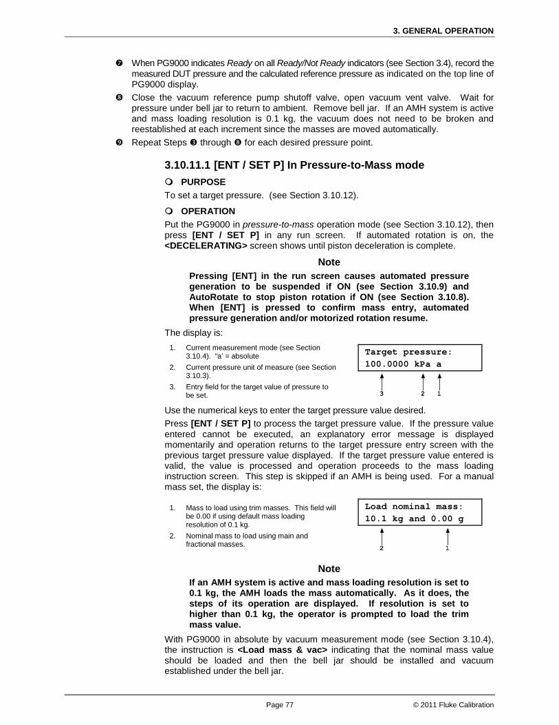
3. GENERAL OPERATION
Page 77 © 2011 Fluke Calibration
When PG9000 indicates Ready on all Ready/Not Ready indicators (see Section 3.4), record the measured DUT pressure and the calculated reference pressure as indicated on the top line of PG9000 display.
Close the vacuum reference pump shutoff valve, open vacuum vent valve. Wait for pressure under bell jar to return to ambient. Remove bell jar. If an AMH system is active and mass loading resolution is 0.1 kg, the vacuum does not need to be broken and reestablished at each increment since the masses are moved automatically.
Repeat Steps through for each desired pressure point.
3.10.11.1 [ENT / SET P] In Pressure-to-Mass mode PURPOSE To set a target pressure. (see Section 3.10.12).
OPERATION Put the PG9000 in pressure-to-mass operation mode (see Section 3.10.12), then press [ENT / SET P] in any run screen. If automated rotation is on, the <DECELERATING> screen shows until piston deceleration is complete.
Note Pressing [ENT] in the run screen causes automated pressure generation to be suspended if ON (see Section 3.10.9) and AutoRotate to stop piston rotation if ON (see Section 3.10.8). When [ENT] is pressed to confirm mass entry, automated pressure generation and/or motorized rotation resume.
The display is: 1. Current measurement mode (see Section
3.10.4). “a’ = absolute 2. Current pressure unit of measure (see Section
3.10.3). 3. Entry field for the target value of pressure to
be set.
Target pressure: 100.0000 kPa a
Use the numerical keys to enter the target pressure value desired. Press [ENT / SET P] to process the target pressure value. If the pressure value entered cannot be executed, an explanatory error message is displayed momentarily and operation returns to the target pressure entry screen with the previous target pressure value displayed. If the target pressure value entered is valid, the value is processed and operation proceeds to the mass loading instruction screen. This step is skipped if an AMH is being used. For a manual mass set, the display is:
1. Mass to load using trim masses. This field will be 0.00 if using default mass loading resolution of 0.1 kg.
2. Nominal mass to load using main and fractional masses.
Load nominal mass: 10.1 kg and 0.00 g
Note If an AMH system is active and mass loading resolution is set to 0.1 kg, the AMH loads the mass automatically. As it does, the steps of its operation are displayed. If resolution is set to higher than 0.1 kg, the operator is prompted to load the trim mass value.
With PG9000 in absolute by vacuum measurement mode (see Section 3.10.4), the instruction is <Load mass & vac> indicating that the nominal mass value should be loaded and then the bell jar should be installed and vacuum established under the bell jar.
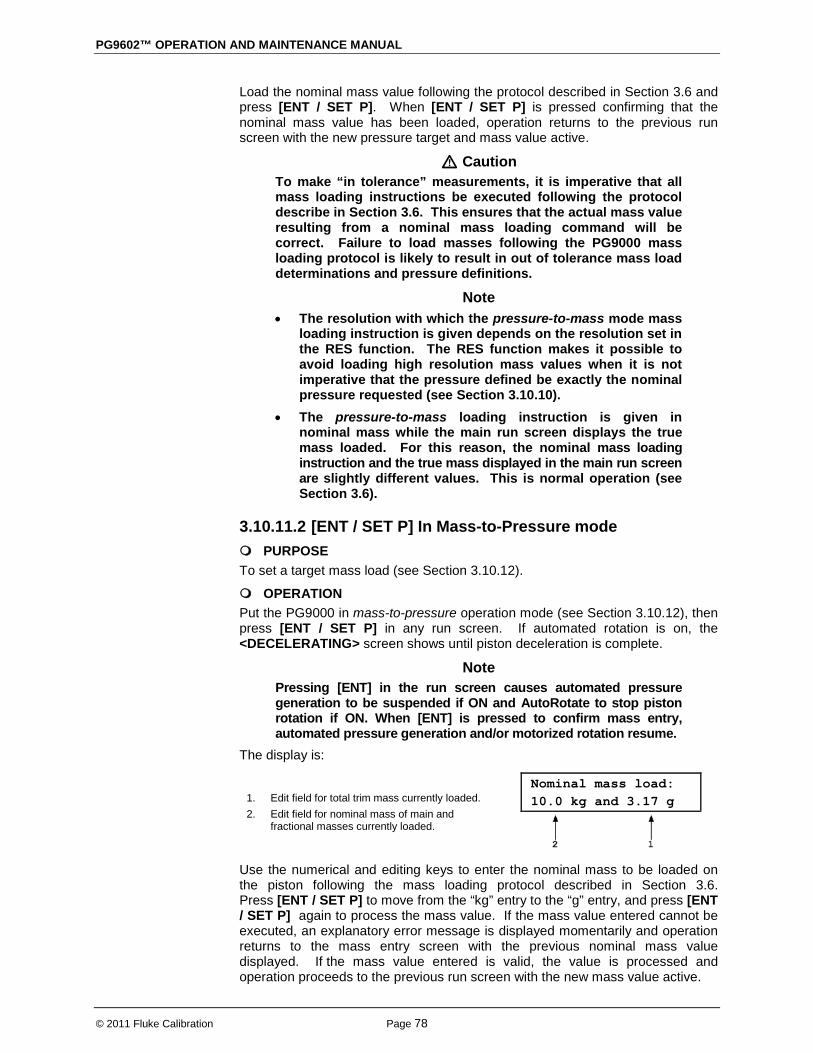
PG9602™ OPERATION AND MAINTENANCE MANUAL
© 2011 Fluke Calibration Page 78
Load the nominal mass value following the protocol described in Section 3.6 and press [ENT / SET P]. When [ENT / SET P] is pressed confirming that the nominal mass value has been loaded, operation returns to the previous run screen with the new pressure target and mass value active.
Caution To make “in tolerance” measurements, it is imperative that all mass loading instructions be executed following the protocol describe in Section 3.6. This ensures that the actual mass value resulting from a nominal mass loading command will be correct. Failure to load masses following the PG9000 mass loading protocol is likely to result in out of tolerance mass load determinations and pressure definitions.
Note • The resolution with which the pressure-to-mass mode mass
loading instruction is given depends on the resolution set in the RES function. The RES function makes it possible to avoid loading high resolution mass values when it is not imperative that the pressure defined be exactly the nominal pressure requested (see Section 3.10.10).
• The pressure-to-mass loading instruction is given in nominal mass while the main run screen displays the true mass loaded. For this reason, the nominal mass loading instruction and the true mass displayed in the main run screen are slightly different values. This is normal operation (see Section 3.6).
3.10.11.2 [ENT / SET P] In Mass-to-Pressure mode PURPOSE To set a target mass load (see Section 3.10.12).
OPERATION Put the PG9000 in mass-to-pressure operation mode (see Section 3.10.12), then press [ENT / SET P] in any run screen. If automated rotation is on, the <DECELERATING> screen shows until piston deceleration is complete.
Note Pressing [ENT] in the run screen causes automated pressure generation to be suspended if ON and AutoRotate to stop piston rotation if ON. When [ENT] is pressed to confirm mass entry, automated pressure generation and/or motorized rotation resume.
The display is:
1. Edit field for total trim mass currently loaded. 2. Edit field for nominal mass of main and
fractional masses currently loaded.
Nominal mass load: 10.0 kg and 3.17 g
Use the numerical and editing keys to enter the nominal mass to be loaded on the piston following the mass loading protocol described in Section 3.6. Press [ENT / SET P] to move from the “kg” entry to the “g” entry, and press [ENT / SET P] again to process the mass value. If the mass value entered cannot be executed, an explanatory error message is displayed momentarily and operation returns to the mass entry screen with the previous nominal mass value displayed. If the mass value entered is valid, the value is processed and operation proceeds to the previous run screen with the new mass value active.
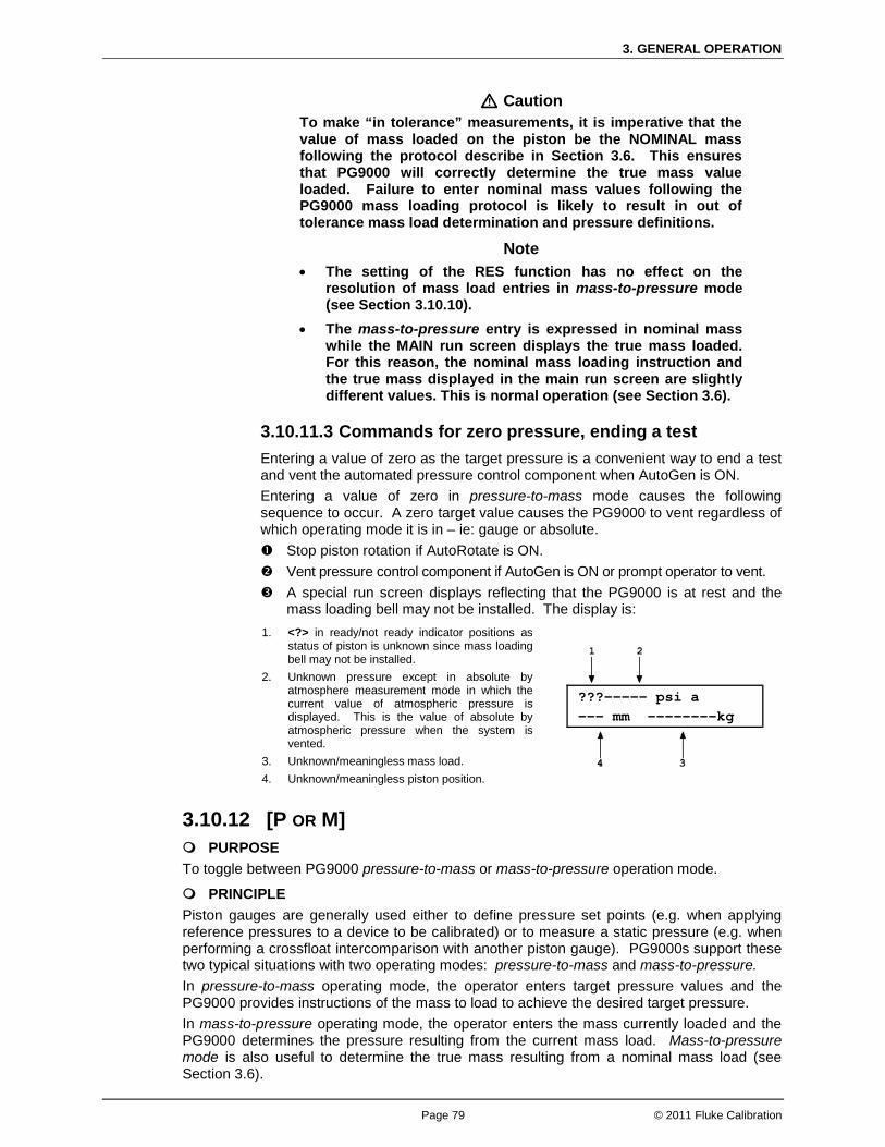
3. GENERAL OPERATION
Page 79 © 2011 Fluke Calibration
Caution To make “in tolerance” measurements, it is imperative that the value of mass loaded on the piston be the NOMINAL mass following the protocol describe in Section 3.6. This ensures that PG9000 will correctly determine the true mass value loaded. Failure to enter nominal mass values following the PG9000 mass loading protocol is likely to result in out of tolerance mass load determination and pressure definitions.
Note • The setting of the RES function has no effect on the
resolution of mass load entries in mass-to-pressure mode (see Section 3.10.10).
• The mass-to-pressure entry is expressed in nominal mass while the MAIN run screen displays the true mass loaded. For this reason, the nominal mass loading instruction and the true mass displayed in the main run screen are slightly different values. This is normal operation (see Section 3.6).
3.10.11.3 Commands for zero pressure, ending a test Entering a value of zero as the target pressure is a convenient way to end a test and vent the automated pressure control component when AutoGen is ON. Entering a value of zero in pressure-to-mass mode causes the following sequence to occur. A zero target value causes the PG9000 to vent regardless of which operating mode it is in – ie: gauge or absolute. Stop piston rotation if AutoRotate is ON. Vent pressure control component if AutoGen is ON or prompt operator to vent. A special run screen displays reflecting that the PG9000 is at rest and the
mass loading bell may not be installed. The display is: 1. <?> in ready/not ready indicator positions as
status of piston is unknown since mass loading bell may not be installed.
2. Unknown pressure except in absolute by atmosphere measurement mode in which the current value of atmospheric pressure is displayed. This is the value of absolute by atmospheric pressure when the system is vented.
3. Unknown/meaningless mass load. 4. Unknown/meaningless piston position.
???----- psi a --- mm --------kg
3.10.12 [P OR M] PURPOSE To toggle between PG9000 pressure-to-mass or mass-to-pressure operation mode.
PRINCIPLE Piston gauges are generally used either to define pressure set points (e.g. when applying reference pressures to a device to be calibrated) or to measure a static pressure (e.g. when performing a crossfloat intercomparison with another piston gauge). PG9000s support these two typical situations with two operating modes: pressure-to-mass and mass-to-pressure. In pressure-to-mass operating mode, the operator enters target pressure values and the PG9000 provides instructions of the mass to load to achieve the desired target pressure. In mass-to-pressure operating mode, the operator enters the mass currently loaded and the PG9000 determines the pressure resulting from the current mass load. Mass-to-pressure mode is also useful to determine the true mass resulting from a nominal mass load (see Section 3.6).

PG9602™ OPERATION AND MAINTENANCE MANUAL
© 2011 Fluke Calibration Page 80
OPERATION
Note For details on pressure-to-mass and mass-to-pressure operation, see Section 3.10.11.
To access the P OR M function, press [P OR M], the display is:
Select entry mode: 1pressure 2mass
Selecting <1pressure> activates pressure-to-mass mode and returns to the previous run screen. Selecting <2mass> activates mass-to-pressure mode and returns to the previous run screen.
3.10.13 [ ] and [ ] + [←] PURPOSE To manually activate motorized piston rotation or braking function.
PRINCIPLE Under normal operations, it is recommend that the motorized rotation should be enabled to automatically engage and disengage the rotation of the PG9000 piston. Motorized rotation can be set to operate automatically to maintain the piston within Ready condition rotation rate limits when the piston is floating and stop rotation before changing the pressure or mass load (see Section 3.10.8). Motorized rotation can also be engaged manually to accelerate or brake the piston rotation at any time under direct operator control. [ ] is used for momentary acceleration of piston rotation. Pressing and holding [ ] followed by [←] is used to start a function that stops piston rotation.
OPERATION To momentarily engage the motorized piston rotation system and accelerate the piston, press and hold [ ] from any run screen. The motorized rotation system engages and remains engaged until maximum rotation rate has been achieved or until the key is released. The display is a modified version of the 1st system run screen to indicate the piston rotation is being accelerated while showing rotation rate and position:
1. Measured piston rotation rate. 2. Current rate of piston vertical displacement. 3. Measured piston position.
12 rpm ACCELERATING + 2.05 mm 0.1/min
To start the piston braking function press and hold [ ], then press [←]. The motorized rotation system engages and stays engaged until the piston rotation is stopped. Once the braking function starts the keys may be released and the function will complete unless [ESC] is pressed.
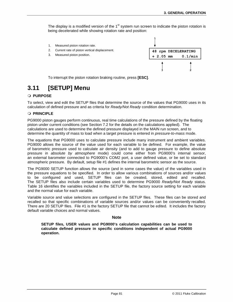
3. GENERAL OPERATION
Page 81 © 2011 Fluke Calibration
The display is a modified version of the 1st system run screen to indicate the piston rotation is being decelerated while showing rotation rate and position:
1. Measured piston rotation rate. 2. Current rate of piston vertical displacement. 3. Measured piston position.
48 rpm DECELERATING + 2.05 mm 0.1/min
To interrupt the piston rotation braking routine, press [ESC].
3.11 [SETUP] Menu PURPOSE
To select, view and edit the SETUP files that determine the source of the values that PG9000 uses in its calculation of defined pressure and as criteria for Ready/Not Ready condition determination.
PRINCIPLE
PG9000 piston gauges perform continuous, real time calculations of the pressure defined by the floating piston under current conditions (see Section 7.2 for the details on the calculations applied). The calculations are used to determine the defined pressure displayed in the MAIN run screen, and to determine the quantity of mass to load when a target pressure is entered in pressure-to-mass mode.
The equations that PG9000 uses to calculate pressure include many instrument and ambient variables. PG9000 allows the source of the value used for each variable to be defined. For example, the value of barometric pressure used to calculate air density (and to add to gauge pressure to define absolute pressure in absolute by atmosphere mode) could come either from PG9000’s internal sensor, an external barometer connected to PG9000’s COM2 port, a user defined value, or be set to standard atmospheric pressure. By default, setup file #1 defines the internal barometric sensor as the source.
The PG9000 SETUP function allows the source (and in some cases the value) of the variables used in the pressure equations to be specified. In order to allow various combinations of sources and/or values to be configured and used, SETUP files can be created, stored, edited and recalled. The SETUP files also include certain variables used to determine PG9000 Ready/Not Ready status. Table 16 identifies the variables included in the SETUP file, the factory source setting for each variable and the normal value for each variable.
Variable source and value selections are configured in the SETUP files. These files can be stored and recalled so that specific combinations of variable sources and/or values can be conveniently recalled. There are 20 SETUP files. File #1 is the factory SETUP file that cannot be edited. It includes the factory default variable choices and normal values.
Note SETUP files, USER values and PG9000’s calculation capabilities can be used to calculate defined pressure in specific conditions independent of actual PG9000 operation.
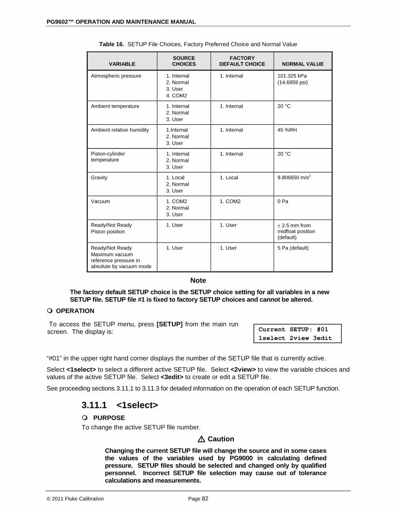
PG9602™ OPERATION AND MAINTENANCE MANUAL
© 2011 Fluke Calibration Page 82
Table 16. SETUP File Choices, Factory Preferred Choice and Normal Value
VARIABLE
SOURCE CHOICES
FACTORY DEFAULT CHOICE
NORMAL VALUE
Atmospheric pressure 1. Internal 2. Normal 3. User 4. COM2
1. Internal 101.325 kPa (14.6959 psi)
Ambient temperature 1. Internal 2. Normal 3. User
1. Internal 20 °C
Ambient relative humidity 1.Internal 2. Normal 3. User
1. Internal 45 %RH
Piston-cylinder temperature
1. Internal 2. Normal 3. User
1. Internal 20 °C
Gravity 1. Local 2. Normal 3. User
1. Local 9.806650 m/s2
Vacuum 1. COM2 2. Normal 3. User
1. COM2 0 Pa
Ready/Not Ready Piston position
1. User 1. User ± 2.5 mm from midfloat position (default)
Ready/Not Ready Maximum vacuum reference pressure in absolute by vacuum mode
1. User 1. User 5 Pa (default)
Note The factory default SETUP choice is the SETUP choice setting for all variables in a new SETUP file. SETUP file #1 is fixed to factory SETUP choices and cannot be altered.
OPERATION
To access the SETUP menu, press [SETUP] from the main run screen. The display is:
Current SETUP: #01 1select 2view 3edit
“#01” in the upper right hand corner displays the number of the SETUP file that is currently active.
Select <1select> to select a different active SETUP file. Select <2view> to view the variable choices and values of the active SETUP file. Select <3edit> to create or edit a SETUP file.
See proceeding sections 3.11.1 to 3.11.3 for detailed information on the operation of each SETUP function.
3.11.1 <1select> PURPOSE To change the active SETUP file number.
Caution Changing the current SETUP file will change the source and in some cases the values of the variables used by PG9000 in calculating defined pressure. SETUP files should be selected and changed only by qualified personnel. Incorrect SETUP file selection may cause out of tolerance calculations and measurements.

3. GENERAL OPERATION
Page 83 © 2011 Fluke Calibration
OPERATION To select a SETUP file number to make it the active SETUP file, press [SETUP] and select <1select>. In the following screen enter the number of the desired SETUP file and press [ENT]. If a valid SETUP file number has been entered, operation returns to the previous run screen with the selected SETUP file number displayed and active.
Note • Entering an invalid SETUP file number causes an error message to be
displayed briefly and returns to the select SETUP file screen. • If the SETUP file selected specifies COM2 as the source of barometric
pressure, PG9000 will attempt to read a barometer on COM2 when initializing the new SETUP file. If PG9000 is unable to read a barometer on COM2, a communications time out message is displayed briefly and operation returns to the select SETUP file screen. See Section 3.12.5.4 for information on configuring COM2 to read an external barometer.
3.11.2 <2view> PURPOSE To view the variable source choices and values of any SETUP file number.
OPERATION
Note • Selecting <2view> SETUP allows the variable source choices and values of
the active SETUP file for viewing only. <2view> does not make the viewed SETUP file active. To select the active SETUP file, press [SETUP] and select <1select>.
• See Table 16 for a listing of the source choices for each variable. To view an existing SETUP file, press [SETUP] and select <2view>. The display is:
1. Entry field for number of SETUP file to be viewed. Defaults to SETUP file currently selected. Must be a number from 2 to 10.
View SETUP file: #02
Enter the desired SETUP file number and press [ENT].
<1atmP> to view the atmospheric pressure variable source choice and current value. The value is displayed in the current pressure units (see Section 3.10.3). <2ambT> to view the ambient temperature variable source choice and the current value. The value is displayed in degrees Centigrade (°C). <3%RH> to view the ambient relative humidity variable source choice and the current value. The value is displayed in “%RH”. <4PCT> to view the piston-cylinder temperature variable source choice and the current value. The value is displayed in degrees Centigrade (°C). <5g> to view the gravity variable source choice and the current value. The value is displayed in meters per second squared (m/s2).
If a valid SETUP file number is entered, the display is: View #02 latmP 2ambT 3%RH 4PCT 5g 6READY 7vac

PG9602™ OPERATION AND MAINTENANCE MANUAL
© 2011 Fluke Calibration Page 84
<6READY> to view the values of Ready/Not Ready status criteria (see Section 3.4). These include:
<1Pposition>: Piston position Ready/Not Ready limits (see Section 3.4.1). The value is displayed as a band in millimeters about mid-float position (± mm). (see Section 3.5).
<2vac>: Maximum reference vacuum pressure limit when operating in absolute by vacuum mode. The value is displayed in Pascal (Pa).
<7vac>: to view the reference vacuum variable source choice and the current value. The value is displayed in Pascal (Pa).
3.11.3 <3edit> PURPOSE To edit an existing SETUP file and/or to create a new SETUP file.
OPERATION
Note • SETUP file #1 is the factory default file and it cannot be edited. • See Table 16 for a listing of the source choices for each variable.
To edit an existing SETUP file or create a new SETUP file, press [SETUP] and select <3edit>. The display is:
1. Entry field for number of SETUP file to be edited or created. Defaults to SETUP file currently selected. Must be a number from 2 to 10.
Edit SETUP file: #02
Enter the desired SETUP file number and press [ENT].
If a valid SETUP file number is entered, the display is: Edit #02 latmP 2ambT 3%RH 4PCT 5g 6READY 7vac
Selecting an item leads to the variable source choices menu for that item. The cursor is on the source choice that is currently selected in that SETUP file number. Select the desired variable source. The selection causes the variable choice selection to be made and returns to the edit menu. From the variable source choice menus, pressing [ENT] or [ESC] returns to the edit selection menu. This allows easy, discreet movement between variable source choices when editing a SETUP file. Select <1atmP> to specify the atmospheric pressure variable source for the pressure values that are used to calculate ambient air density and to add to gauge pressure measurements to calculate absolute pressure in absolute by addition of atmosphere mode. Selecting <1atmP> offers the atmospheric pressure variable source choices:
<1internal> Use real time readings from PG9000’s on-board barometer.
<2normal> Use a fixed value of 101.325 kPa (14.6959) psi.
<3user> Use a fixed user defined value. If <3user> is selected, the user value must be entered, in the current pressure unit of measure (see Section 3.10.3).
<4COM2> Use real time readings from the device connected by RS232 to PG9000’s COM2 port. The external barometer must be properly set up to communicate with PG9000 (see Section 3.12.5.4 for information on setting up to read an external barometer).
Note For differential mode operation (see Section 3.10.4.1) the AtmP selection must be <4COM2>.

3. GENERAL OPERATION
Page 85 © 2011 Fluke Calibration
Select <2ambT> to specify the ambient temperature variable source for the temperature values that are used to calculate ambient air density. Selecting <2ambT> offers the temperature variable source choices:
<1internal>: Use real time readings from PG9000’s ambient temperature platinum resistance thermometer in the Temperature - Humidity (TH) Probe.
<2normal>: Use a fixed value of 20 °C.
<3user>: Use a fixed user defined value. If <3user> is selected, the user value must be entered, in degrees Centigrade (°C).
Select <3%RH> to specify the relative humidity variable source for the relative humidity values that are used to calculate ambient air density. Selecting <3%RH> offers the relative humidity variable source choices:
<1internal>: Use real time readings from PG9000’s relative humidity sensor in the Temperature - Humidity (TH) Probe.
<2normal>: Use a fixed value of 45 %RH.
<3user>: Use a fixed user defined value. If <3user> is selected, the user value must be entered, in percent relative humidity (%RH).
Select <4PCT> to specify the piston-cylinder temperature variable source for the temperature values that are used to compensate for thermal expansion of the piston-cylinder effective area. Selecting <4PCT> offers the temperature variable source choices:
<1internal>: Use real time readings from PG9000’s on-board piston-cylinder temperature platinum resistance thermometers (embedded in the piston-cylinder module mounting post).
<2normal>: Use a fixed value of 20 °C.
<3user>: Use a fixed user defined value. If <3user> is selected, the user value must be entered, in degrees Centigrade (°C).
Select <5g> to specify the value of acceleration due to gravity that is used in calculating the force applied to the piston. Pressing <5g> offers the gravity variable source choices:
<1locall>: Use the fixed value of local gravity stored under [SPECIAL], <6gl> (see Section 3.12.6).
<2normal>: Use a fixed value of 9.806650 m/s2.
<3user>: Use a fixed user defined value different from the current local gravity value stored in the [SPECIAL], <6gl> menu option. If <3user> is selected, the user value must be entered in units of meters per second squared (m/s2).
Select <6READY> to edit the values of Ready/Not Ready status criteria (see Section 3.4). These include:
<1Pposition>: Piston position limits. Edit the fixed value, in millimeters (mm), of the band around mid-float position within which the piston position is Ready (see Section 3.4.1). This also determines the limit at which the piston is refloated by the GEN function when GEN is ON (see Section 3.10.9).
<2vac>: Maximum reference vacuum pressure when operating in absolute by vacuum mode. Edit the value, in Pascal (Pa), under which the reference vacuum must be for a vacuum Ready condition to occur (see Section 3.4.3).

PG9602™ OPERATION AND MAINTENANCE MANUAL
© 2011 Fluke Calibration Page 86
Select <7vac> to specify the reference vacuum variable source for the value used for the pressure under the bell jar when calculating the absolute pressure defined in absolute by vacuum mode. Pressing <7vac> offers the reference vacuum variable source choices:
<1COM2>: Use real time readings from the device connected by RS232 to PG9000’s COM2 port. <1COM2> is the selection for the standard PG9000 reference vacuum sensor included with the optional vacuum reference hardware. If a different external vacuum gauge is used in place of the default, it must be properly set up to communicate with PG9000 (see Section 3.12.5.5).
<2normal>: Use a fixed value of 0 Pa.
<3user>: Use a fixed user entered value. If <3user> is selected, the user value must be entered, in Pascal (Pa).
3.12 [SPECIAL] Menu PURPOSE
The [SPECIAL] key accesses a menu of PG9000 functions and settings that are less commonly or not regularly used in normal operation.
OPERATION
To access the SPECIAL menu, press [SPECIAL] from the main run screen. This display is:
1PC/MS 2presU 3head
4prefs 5remote 6gl
7cal 8AMH 9reset
Note Some screens, such as the SPECIAL menu, go beyond the two lines provided by the display. This is indicated by a flashing arrow in the second line of the display. Press the [←] and [→] keys to move the cursor to access the lines that are NOT visible or directly enter the number of the hidden menu choice if you know it.
Special menu choices include:
<1PC/MS>: Edit and view stored piston-cylinder module and mass set metrological information. Select mass set to be used (see Section 3.12.1).
<2presU>: Customize the pressure unit of measure choices available under [UNIT] (see Section 3.12.2).
<3head>: Change the height unit of measure and the fluid used in DUT head corrections; adjust the barometer head height; turn the automated piston position head correction ON and OFF (see Section 3.12.3).
<4prefs>: To access a menu of internal PG9000 operational preferences and functions including screen saver, sounds, time/date, instrument ID and user level protection (see Section 3.12.4).
<5remote>: Set up/modify PG9000 RS232 (COM1, COM2, COM3, COM4) and IEEE-488 interfaces. Test RS232 ports. Set up external barometer or vacuum gauge communications (see Section 3.12.5).
<6gl>: Set the value of local gravity used by PG9000 in reference pressure calculations when gl is specified as the gravity value in the active SETTINGS file (see Section 3.12.6).
<7cal>: View the output and/or adjust PG9000 internal sensors and measurement systems (see Section 3.12.7).
<8AMH>: View the status and directly control an AMH (see Section 3.12.8).
<9reset>: Access and execute various reset options (see Section 3.12.9).
3. GENERAL OPERATION
Page 87 © 2011 Fluke Calibration
3.12.1 <1PC/MS> PURPOSE To perform the following piston-cylinder module and mass set metrological functions: • View and edit piston-cylinder module metrological information. • Create new piston-cylinder modules. • View and edit mass set and mass loading bell information. • Create new mass sets and mass loading bells. • Select the active mass set and mass loading bell.
Note See Section 3.10.2 for information on more direct access to selecting the active piston-cylinder module.
Caution The piston-cylinder module and mass set information contained in <1PC/MS> is element specific metrological data. Uninformed or accidental altering of this information may lead to out of tolerance measurements. Piston-cylinder module and mass set information should only be edited by qualified personnel as part of the PG9000 calibration or recalibration process.
PRINCIPLE To calculate the pressure defined by its floating piston, PG9000 must have available the specific characteristics of the piston-cylinder module, mass set and mass loading bell that are being used. This information is entered, viewed and edited under [SPECIAL], <1PC/MS>. This is also where the active mass and mass loading bell are selected. The piston-cylinder module and mass set information required by PG9000 is reported on the calibration reports that are delivered with the metrological elements. When the PG9000 Platform and metrological elements are delivered together, the metrological data information is entered by Fluke Calibration at the factory. If the metrological elements are delivered separately from the platform, or after a recalibration when new data is available, the information must be updated by the user.
OPERATION
To access the piston-cylinder, mass set and mass loading bell information, press [SPECIAL] and select <1PC/MS>. The display is:
1PC 2mass set 3mass bell
Select the type of metrological data that you would like to view, edit, create or select. See Sections 3.12.1.1 to 3.12.1.15 for operation of specific piston-cylinder module, mass set and mass bell functions as follows: • Create a new piston-cylinder module (see Section 3.12.1.1). • Edit piston-cylinder module information (see Section 3.12.1.2). • View piston-cylinder module information (see Section 3.12.1.3). • Delete a piston-cylinder module (see Section 3.12.1.4). • Select the active piston-cylinder module (see Section 3.12.1.5). • Create a new mass set (see Section 3.12.1.6). • Edit mass set information (see Section 3.12.1.7). • View mass set information (see Section 3.12.1.8). • Delete a mass set (see Section 3.12.1.9). • Select a mass set (see Section 3.12.1.10). • Add a mass loading bell (see Section 3.12.1.11).
PG9602™ OPERATION AND MAINTENANCE MANUAL
© 2011 Fluke Calibration Page 88
• Edit mass loading bell information (see Section 3.12.1.12). • View the active mass loading bell (see Section 3.12.1.13). • Delete a mass loading bell (see Section 3.12.1.14). • Select a mass loading bell (see Section 3.12.1.15).
3.12.1.1 Create a Piston-Cylinder Module PURPOSE To create a new piston-cylinder module that will be available for selection from the [P-C] function key. Use this function when a new piston-cylinder module has been acquired.
Note If the piston-cylinder module and PG9000 Platform were delivered together, the piston cylinder metrological data has already been entered at the factory. Before creating a new piston-cylinder module, press [P-C] to check if it already exists (see Section 3.10.2).
PRINCIPLE The PG9000 add and edit piston-cylinder module functions allow piston-cylinder metrological data to be defined and stored. This data will be used by PG9000 in calculating the defined pressure, piston-cylinder range, pressure-to-mass and mass-to-pressure values when the piston-cylinder module is made active. The required data can be found in the calibration report for the piston-cylinder module. Setting up or editing a piston-cylinder module requires specifying, in sequential order, the following:
Serial number (S/N) [nnnn].
Effective area (Ae) at 0 kPag pressure and 20 °C [mm2].
Piston temperature coefficient [linear thermal expansion/°C].
Cylinder temperature coefficient [linear thermal expansion/°C].
Effective area pressure coefficient [change in Ae/MPa].
Piston-cylinder surface tension effect [N/m].
Reference level offset [mm].
Piston assembly mass (true mass) [kg].
Piston assembly average density [kg/m3].
Rotation rate ready limits [rpm].
k(P) [kg/mm/min].
Calibration report number [nnnnnnnnnn].
Calibration report date [yyyymmdd].
OPERATION
Note • PG9000 can store up to 18 piston-cylinder module (PC) files.
When <3add> is selected and all the files have already been used, a warning is displayed -- a file must be deleted before a file can be added.

3. GENERAL OPERATION
Page 89 © 2011 Fluke Calibration
To create a new piston-cylinder module press [SPECIAL] , <1PC/MS> and select <1PC>, <3add>. A series of data entry menus will be presented. Edit each menu to reflect the correct information on the piston-cylinder module being added. Press [ENT] after each entry to proceed to the next menu. Pressing [ESC] at any point offers an <Abandon edits?> query and then returns to the <1PC> menu without saving any of the edited data or [ENT] returns to the add piston-cylinder module process. The data entry screens to add or edit a piston-cylinder module are, in order:
• Serial number (S/N): Edit the serial number using four digits. This value is marked on the piston cap. The default is 1.
• Effective area at 0 pressure and 20 °C: Edit the value of the piston-cylinder effective area at 0 pressure and 20 °C. The value must be entered in square millimeters [mm2]. This value is reported in the calibration report for the piston-cylinder module. The default is 0.
• Piston temperature coefficient: Edit the value of the piston material linear thermal expansivity. The value must be entered in terms of relative change per degree centigrade [nn x 10-6/°C]. The E-6 exponent is fixed. This value is reported in the calibration report for the piston-cylinder module. The default is 00.
• Cylinder temperature coefficient: Edit the value of the cylinder material linear thermal expansivity. The value must be entered in terms of relative change per degree centigrade [nn x 10-6/°C]. The 10-6 exponent is fixed. This value is reported in the calibration report for the piston-cylinder module. The default is 00.
• Effective area pressure coefficient: Edit the value of the piston-cylinder change in effective area in terms of relative change per MegaPascal [n.nn x 10-6/MPa]. This value is reported in the calibration report for the piston-cylinder module. The default is 0.00.
• Piston-cylinder surface tension effect: Edit the value of the surface tension effect of the pressurized fluid on the piston. The value must be entered in Newtons per meter [N/m]. This value is reported in the calibration report for the piston-cylinder module. The default is 0.00. The correct value for all gas lubricated, gas operated piston-cylinders is 0.
• Reference level offset: Edit the value of the reference level offset which corrects the piston-cylinder reference level for hollow pistons (10 kPa/kg, 20 kPa/kg and 50 kPa/kg gas lubricated piston-cylinder modules only) to the reference level marked on the mounting post (see Section 3.10.7). The value must be entered in millimeters [mm]. This value is reported in the calibration report. It is 0 mm for the 100 kPa/kg and 200 kPa/kg piston-cylinders. The default is 0.00.
• Piston assembly mass: Edit the value of the mass of the piston assembly (piston + piston head + piston cap). The value must be entered in kilogram [kg]. This value is reported in the calibration report for the piston-cylinder module. The default is 0.200000.
• Piston assembly average density: Edit the value of the average density of the piston assembly (piston + piston head + cap). The value must be entered in kilogram per cubic meter [kg/m3]. This value is reported in the calibration report for the piston-cylinder module. The default is 0.
• Rotation rate ready limits [rpm]: The minimum Ready rotation rate (see Section 3.4.2) and the target maximum rate. The values must be entered in rotations per minute [rpm]. The values (min and max) must be entered in rotations per minute [rpm]. The value automatically defaults to the factory recommended value for the piston-cylinder size and pressurized medium. In most circumstances, the factory default values should be used.

PG9602™ OPERATION AND MAINTENANCE MANUAL
© 2011 Fluke Calibration Page 90
• k(P) coefficient [kg/mm/min]: Edit the value of the mass to equilibrium fall rate proportionality coefficient. This value is not used for PG9000. The default value is 0.00.
• Calibration report number: Edit the calibration report number to reflect the number of the piston-cylinder module calibration report that is currently valid. The number can be up to ten digits. The default is 1.
• Calibration report date: Edit the date of the current calibration report. The date must be expressed in yyyymmdd format. The default is 20000101.
After pressing [ENT] to accept the edited calibration report date, the option to save the edited piston-cylinder module information is presented. The display is:
Save PC S/N nnnn 1no 2yes
Select <2yes> to save the piston-cylinder module information under serial number nnnn and return to the <1PC/MS> menu. Select <1no> to discard all edits and return to the <1PC/MS> menu.
3.12.1.2 Edit a Piston-Cylinder Module PURPOSE To edit information contained in an existing piston-cylinder module file. Use this function to change piston-cylinder module data after a recalibration.
PRINCIPLE & OPERATION
Caution Piston-cylinder module information is element specific metrological data. Uninformed or accidental altering of this information may lead to out of tolerance measurements. Piston cylinder module information should only be edited by qualified personnel as part of the PG9000 calibration or recalibration process.
The previous section describes adding a new piston-cylinder module. The principles and procedures to edit a piston-cylinder module are identical to the process for adding a new one except for the identification of the piston-cylinder module to be edited. To edit information on an existing piston-cylinder module, press [SPECIAL] , <1PC/MS> and select <1PC>, <2edit>. The display identifies the currently active piston-cylinder module. Press [ENT] to edit the active piston-cylinder module or press [P-C] or [←] or [→] to cycle through the other piston-cylinder modules available. When the desired piston-cylinder module is identified, press [ENT] to activate and proceed with editing piston-cylinder module information. Operation of the editing function is identical to the add new piston-cylinder module procedure (see Section 3.12.1.1, OPERATION).
3.12.1.3 View a Piston-Cylinder Module PURPOSE To view the information contained in an existing piston-cylinder module file.
PRINCIPLE & OPERATION See Section 3.12.1.1, PRINCIPLE. The piston-cylinder module viewing function allows the piston-cylinder module information to be viewed but not altered. To view information on an existing piston-cylinder module, press [SPECIAL] , <1PC/MS> and select <1PC>, <3view>.
3. GENERAL OPERATION
Page 91 © 2011 Fluke Calibration
The display identifies the active piston-cylinder module. Press [ENT] to view the active piston-cylinder module or press [P-C] or [←] or [→] to cycle through the other piston-cylinder modules available (see Section 3.10.2). When the desired piston cylinder module is identified, press [ENT] to proceed with viewing piston-cylinder module information. Successive pressing of [ENT] steps through the piston-cylinder information screens in the same order as the add and edit functions (see Section 3.12.1, View Piston-Cylinder Module, Principle
3.12.1.4 Delete a Piston-Cylinder Module
).
PURPOSE To delete a piston-cylinder module file so that it is no longer included in the piston-cylinder modules available for selection by pressing [P-C].
OPERATION
Caution Once a piston-cylinder module file has been deleted it cannot be recovered. To recreate it, the add piston-cylinder module function must be used (see Section 3.12.1.1) which requires entering all the piston-cylinder module information. Before deleting a piston-cylinder module, consider editing it (see Section 3.12.1.2).
To delete a piston-cylinder module press [SPECIAL] , <1PC/MS> and select <1PC>, <4delete>. The display identifies the active piston-cylinder module. Press [P-C] or press [←] or [→] to advance through the piston-cylinder modules available (see Section 3.10.2). When the desired piston cylinder module is identified, press [ENT] to proceed with deleting the piston cylinder module information. Confirmation to delete is required. Select <2yes> to delete the piston-cylinder module. Select <1no> to NOT delete.
Note The active piston-cylinder module (piston-cylinder module that is currently selected) cannot be deleted. Before attempting to delete a piston-cylinder module, be sure it is not currently selected.
3.12.1.5 Select The Active Piston-Cylinder Module PURPOSE To select the piston-cylinder module that is to active and to be used by PG9000 in calculating the defined pressure.
OPERATION To select the active piston-cylinder module press [SPECIAL], <1PC/MS> and select <1PC>, <5select>. The display identifies the active piston-cylinder module. Press [P-C] or press [←] or [→] to advance through the piston-cylinder modules available (see Section 3.10.2). When the desired piston cylinder module is identified, press [ENT] to make active.
3.12.1.6 Add a Mass Set PURPOSE To create a new mass set that will be available for selection as an active mass set. Use this function when a new mass set has been acquired or a mass set was deleted and must be reentered.

PG9602™ OPERATION AND MAINTENANCE MANUAL
© 2011 Fluke Calibration Page 92
Note If the mass set and PG9000 Platform were delivered together, the mass set data was entered at the factory. Before creating a new mass set, check whether it already exists using the view mass set function (see Section 3.12.1.8).
PRINCIPLE The PG9000 add and edit mass set functions allow mass set composition and metrological data to be defined and stored. These values will be used by PG9000 when the mass set is made active to calculate nominal mass instructions and true mass loads. Up to three mass sets can be stored. Setting up or editing a mass set requires defining the density of the masses, the mass set composition and the true mass
Note
value of each individual mass. This information can be found in the calibration report for the mass set.
The calculated reference pressure is based on using True Mass values – do not use apparent mass values when defining a mass set.
Mass sets are created and edited in terms of mass groups reflecting the normal composition of a PG9000 mass set. Standard PG9000 mass sets are made up of these groups (see Section 2.1.2.2 for listings of standard PG9000 mass set compositions, and Section 3.6 on the theory of mass loading protocol). The mass groups of a MANUAL mass set include: 1. Make Up mass (4 or 9 kg): A single mass, sequentially numbered 1.
The value of this mass is 9 kg if the mass set main masses are 10 kg and 4 kg if the mass set main masses are 5 kg. The purpose of this mass is to arrive at a whole number nominal mass load equal to the set’s main masses (10 kg or 5 kg) when added to the piston and mass loading bell.
2. 10 kg masses: The main masses in a standard 80 or 100 kg mass set. Sequentially numbered from 1 up to the total number of 10 kg masses. Mass sets of less than 80 kg do not normally include 10 kg masses.
3. 5 kg masses: The main masses in any standard mass set of less than 80 kg. Sequentially numbered from 1 up to the total number of 5 kg masses. Standard 80 and 100 kg mass sets have one 5 kg mass.
4. 2 kg masses: Every standard mass set has two 2 kg masses numbered 1 and 2.
5. 1 kg masses: Every standard mass set has one 1 kg mass numbered 1. 6. 0.5 kg masses: Every standard mass set has one 0.5 kg mass number 1. 7. 0.2 kg masses: Every standard mass set has two 0.2 kg masses numbered 1
and 2. 8. 0.1 kg masses: Every standard mass set has one 0.1 kg mass numbered 1. 9. Trim masses: Every standard mass set has a trim mass set made up of
masses from 50 to 0.01 g. These masses are NOT defined and entered as part of the mass set.
The mass groups for an AMH mass set include: 1. 10.1 kg Main masses: Sequentially numbered from 1 to a maximum of 9. 2. 6.4 kg mass: Single tubular, binary mass. 3. 3.2 kg mass: Single tubular, binary mass. 4. 1.6 kg mass: Single tubular, binary mass. 5. 0.8 kg mass: Single tubular, binary mass. 6. 0.4 kg mass: Single tubular, binary mass.

3. GENERAL OPERATION
Page 93 © 2011 Fluke Calibration
7. 0.2 kg mass: Single tubular, binary mass. 8. 0.1 kg mass: Single tubular, binary mass. 9. Trim masses: Every standard mass set has a trim mass set made up of
masses from 50 to 0.01 g. These masses are NOT defined and entered as part of the mass set.
Caution When PG9000 provides mass loading instructions and calculates the true mass of the mass currently loaded, it assumes that the mass set in use has been set up correctly and that masses have been loaded following PG9000 mass loading protocol (see Section 3.6). For PG9000 mass loading protocol to operate properly, the mass set in use must be EXACTLY the mass set that has been defined by the add and/or edit mass function. No extra mass can be included, no mass used can be missing and the sequential numbers of masses in each mass group must be followed with the correct true mass value entered for each individual mass. Using a mass set that is not accurately set up may result in out of tolerance pressure definitions.
Note Though the piston and the mass loading bell constitute part of the mass load, they are not included in the definition of a mass set. Also, one PG9000 system may be used with several piston-cylinder modules, mass loading bells and mass sets. Therefore, the piston mass and mass loading bell mass information are not part of the mass set. Piston mass information is defined and stored in the piston-cylinder module file (see Section 3.12.1.1) and mass loading bell information is defined and stored in a separate mass loading bell files (see Section 3.12.1.11). In an AMH mass set, the binary mass carrier and mass lifting shaft are considered part of the bell.
OPERATION
To create a new PG9000 mass set there are three sequential steps:
Initialize mass set: Define the serial number, density, mass set type (manual or AMH), calibration report number and date.
Define the individual masses: edit, add and delete mass groups as necessary to identify and define all masses in the mass set.
Save mass set file or abandon changes.
Press [SPECIAL] , <1PC/MS> and select <2mass set>, <3add>. Step : Initialize Mass Set
Edit the serial number to the number of the mass set being added and press [ENT]. The display is:
Add mass set: S/N 1
Edit the density of the masses being added (all PG9000 mass sets have density of 8000 kg/m3) and press [ENT]. The display is:
Mass density: 8000 kg/m3
Select <1manual> for a manual mass set or <2AMH> for an automated mass handler mass set.
Mass set type: 1manual 2AMH

PG9602™ OPERATION AND MAINTENANCE MANUAL
© 2011 Fluke Calibration Page 94
Edit the calibration report number (up to ten digits) to the number of the current calibration report of the mass set that is being added and press [ENT]. The display is:
Cal report number? 1
Edit the calibration report date to the date of the current calibration report of the mass set that is being added (format must be YYYYMMDD) and press [ENT]. [ENT] leads to the second step of mass set adding or editing.
Cal report date? 20000101
Pressing [ESC] at any point goes to an abandon edits warning screen. To continue with defining the mass set proceed to Step .
Caution Mass set information is element specific metrological data. Uninformed or accidental altering of this information may lead to out of tolerance measurements. Mass set information should only be edited by qualified personnel as part of the PG9000 calibration or recalibration process.
Note • To use the create or edit mass set function with a manual
mass set, it is important to have an understanding of mass set structure and mass groups. Consult Section 3.6, PRINCIPLE, to familiarize yourself with this information before attempting to create or edit a mass set. Before creating or editing an AMH automated mass handler mass set, see Section 3.7.
• PG9000 can store up to 3 MS (mass set) files. When <3add> is selected and all the files have already been used, a warning is displayed. A mass set must be deleted before a mass set can be added.
This step can only be reached by going through Step . Step : Define Individual Masses
If the mass set is a MANUAL mass set, the display is:
(Note: this is the default screen. For the 80 and 100 kg mass set, a 10 kg mass group must be ADDED to allow the 10 kg masses to be programmed.)
Select mass grp (kg) MKUP 5.00 2.00 1.001 0.50 0.20 0.10 ADD
If the mass set is an AMH mass set, the display is:
Select mass grp (kg) MAIN 6.40 3.20 1.60 0.80 0.40 0.20 0.10
Note Some screens, such as the SPECIAL menu, go beyond the two lines provided by the display. This is indicated by a flashing downward pointing arrow on the second line of the display. Press the [←] and [→] keys to move the cursor to access the lines that are NOT visible or directly enter the number of the hidden menu choice if you know it.
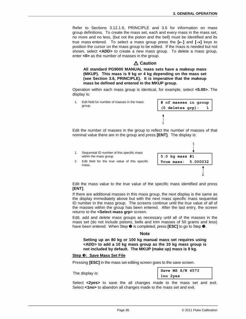
3. GENERAL OPERATION
Page 95 © 2011 Fluke Calibration
Refer to Sections 3.12.1.6, PRINCIPLE and 3.6 for information on mass group definitions. To create the mass set, each and every mass in the mass set, no more and no less, (but not the piston and the bell) must be identified and its true mass entered. To select a mass group press the [←] and [→] keys to position the cursor on the mass group to be edited. If the mass is needed but not shown, select <ADD> to create a new mass group. To delete a mass group, enter <0> as the number of masses in the group.
Caution All standard PG9000 MANUAL mass sets have a makeup mass (MKUP). This mass is 9 kg or 4 kg depending on the mass set (see Section 3.6, PRINCIPLE). It is imperative that the makeup mass be defined and entered in the MKUP group.
Operation within each mass group is identical, for example, select <5.00>. The display is:
1. Edit field for number of masses in the mass group.
# of masses in group (0 deletes grp): 1
Edit the number of masses in the group to reflect the number of masses of that nominal value there are in the group and press [ENT]. The display is:
1. Sequential ID number of this specific mass within the mass group.
2. Edit field for the true value of this specific mass.
5.0 kg mass #1 True mass: 5.000032
Edit the mass value to the true value of the specific mass identified and press [ENT]. If there are additional masses in this mass group, the next display is the same as the display immediately above but with the next mass specific mass sequential ID number in the mass group. The screens continue until the true value of all of the masses within the group has been entered. After the last entry, the screen returns to the <Select mass grp> screen. Edit, add and delete mass groups as necessary until all of the masses in the mass set (do not include pistons, bells and trim masses of 50 grams and less) have been entered. When Step is completed, press [ESC] to go to Step .
Note Setting up an 80 kg or 100 kg manual mass set requires using <ADD> to add a 10 kg mass group as the 10 kg mass group is not included by default. The MKUP (make up) mass is 9 kg.
Pressing [ESC] in the mass set editing screen goes to the save screen.
Step : Save Mass Set File
The display is: Save MS S/N 4573 1no 2yes
Select <2yes> to save the all changes made to the mass set and exit. Select <1no> to abandon all changes made to the mass set and exit.
PG9602™ OPERATION AND MAINTENANCE MANUAL
© 2011 Fluke Calibration Page 96
3.12.1.7 Edit a Mass Set PURPOSE To edit information contained in an existing mass set file. Use this function to change mass set data after a recalibration or if a mass set configuration changes.
PRINCIPLE & OPERATION
Caution Mass set information is element specific metrological data. Uninformed or accidental altering of this information may lead to out of tolerance measurements. Mass set information should only be edited by qualified personnel as part of the PG9000 calibration or recalibration process.
See Section 3.12.1.6 describing adding a new mass set. The principles and procedures to add or edit a mass set are identical except that the mass set to edit is selected from the existing mass sets screen. The mass set type (manual or AMH) cannot be changed when a mass set is edited.
3.12.1.8 View a Mass Set PURPOSE To view the individual mass set details of an existing mass set.
OPERATION To view information contained in an existing mass set file press [SPECIAL], <1PC/MS> and select <2mass set>, <1view>. The viewing function operates in the same manner as the add function (see Section 3.12.1.6).
3.12.1.9 Delete a Mass Set PURPOSE To delete an existing mass set file.
OPERATION
Caution Once a mass set file has been deleted it cannot be recovered. To recreate it, the add mass set function must be used (see Section 3.12.1.6) which requires entering all the mass set information. Before deleting a mass set, consider editing it (see Section 3.12.1.7).
To delete a mass set press [SPECIAL], <1PC/MS> and select <2mass set>, <4delete>. Select the mass set to be deleted and press [ENT]. Select <2yes> to confirm the mass set deletion. Press <1no> to NOT delete.
Note The active mass set (mass set that is currently selected) cannot be deleted. Before attempting to delete a mass bell, be sure it is not currently selected.
3.12.1.10 Select Mass Set PURPOSE To select a mass set to be active and used by PG9000 in its calculation of the reference pressure. To initialize the optional AMH automated if present.

3. GENERAL OPERATION
Page 97 © 2011 Fluke Calibration
OPERATION To select the active mass set press [SPECIAL], <1PC/MS> and select <2mass set>, <5select>. Mass sets for an AHM are identified by a letter <A> after their serial number. Put the cursor on the desired mass set and press [ENT]. If a MANUAL mass set is selected, operation returns to the MAIN run screen. If an AMH mass set is selected, the PG9000 platform attempts to establish communication with the AMH and initialize it. If the communication cannot be established with the AMH, an error is displayed. If communication with the AMH is established, then it’s initialized and all masses are loaded. This initialization process is the same that occurs when pressing [SPECIAL], <8AMH>, <2control>, <3loadall>. If the AMH is unable to complete initialization, an error message is displayed. The most common reason for failure to complete initialization is inadequate drive pressure supply to the AMH. If the AMH initialization completes successfully, operation returns to the main run screen with the AMH active. The AMH remains active until a non-AMH mass set is selected. The PG9000 platform will attempt to initialize the AMH on power up if an AMH mass set is the active mass set.
3.12.1.11 Add a Mass Loading Bell PURPOSE To create a new mass loading bell that will be available for selection as the active mass loading bell. Use this function when a new mass bell has been acquired.
Note If the mass loading bell and PG9000 Platform were delivered together, the mass loading bell has already been entered at the factory. Before creating a new mass loading bell, check whether it already exists (see Section 3.12.1.13).
PRINCIPLE The principle is the same as adding a new mass set. See Section 3.12.1.6, PRINCIPLE.
OPERATION
Caution Mass loading bell information is element specific metrological data. Uninformed or accidental altering of this information may lead to out of tolerance measurements. Mass loading bell information should only be edited by qualified personnel as part of the PG9000 calibration or recalibration process.
Note PG9000 can store up to 3 mass bell files. When <3add> is selected and all the files have already been used, a warning is displayed. A mass loading bell must be deleted before a mass loading bell can be added.
To create a new PG9000 mass loading bell press [SPECIAL] and select <1PC/MS>, <3mass bell>, <3add>.
Edit the serial number to the number of the mass bell being added and press [ENT]. The display is:
Add mass bell: S/N 1

PG9602™ OPERATION AND MAINTENANCE MANUAL
© 2011 Fluke Calibration Page 98
Edit the average mass density of the mass loading bell and press [ENT]. The value defaults to the default density for the typical mass loading bell for the PG9000 model. The display is:
Mass density? 5058 kg/m3
Note The AMH automated mass handler mass bell includes the bell, the binary mass carrier and the mass lifting shaft.
Edit the calibration report number (up to ten digits) to the number of the current calibration report of the mass loading bell that is being added and press [ENT]. The display is:
Cal report number? 1775
Edit the calibration report date to the date of the current calibration report of the mass loading bell that is being added and press [ENT]. The display is:
Cal report date? 20040101
Edit the true mass value of the mass loading bell that is being added and press [ENT]. The value defaults to the nominal mass of the typical mass loading bell for the PG9000 model. The display is:
Bell #2832 True mass: 0.799985
Select <2yes> to save the all changes made to the mass loading bell and exit. Select <2no> to abandon all changes made to the mass loading bell and exit.
Save bell S/N 2832? 1no 2yes
3.12.1.12 Edit a Mass Loading Bell PURPOSE To edit information contained in an existing mass loading bell file. Use this function to change mass loading bell data after a recalibration.
PRINCIPLE & OPERATION
Caution Mass loading bell information is element specific metrological data. Uninformed or accidental altering of this information may lead to out of tolerance measurements. Mass loading bell information should only be edited by qualified personnel as part of the PG9000 calibration or recalibration process.
See Section 3.12.1.11 describing adding a new mass loading bell. The principles and procedures to add or edit a mass loading bell are identical except that the mass loading bell to edit is selected from the existing mass loading bell screen.
3.12.1.13 View a Mass Loading Bell PURPOSE To view information contained in an existing mass loading bell file.
OPERATION To view information contained in an existing mass loading bell file press [SPECIAL] and select <1PC/MS>, <3mass bell>, <1view>. The viewing function is identical to the add function (see Section 3.12.1.11).

3. GENERAL OPERATION
Page 99 © 2011 Fluke Calibration
3.12.1.14 Delete A Mass Loading Bell PURPOSE To delete an existing mass loading bell file entirely.
OPERATION
Caution Once a mass loading bell file has been deleted it cannot be recovered. To recreate it, the add mass loading bell function must be used (see Section 3.12.1.11) which requires entering all the mass loading bell information. Before deleting a mass loading bell, consider editing it (see Section 3.12.1.12).
To delete a mass loading bell press [SPECIAL], <1PC/MS> and select <3mass bell>, <4delete>. Confirmation to delete is requested. Select <2yes> to delete the mass loading bell. Press <1no> to NOT delete.
Note The active mass bell (mass bell that is currently selected) cannot be deleted. Before attempting to delete a mass bell, be sure it is not currently selected.
3.12.1.15 Select a Mass Loading Bell PURPOSE To select the mass loading bell that is active and used by PG9000 in its mass loading and calculation of the reference pressure.
OPERATION To select the active mass loading bell set press [SPECIAL], <1PC/MS> and select <3mass bell>, <5select>.
3.12.2 <2presU> PURPOSE To customize the selection of pressure units that are available for selection from the UNIT function key (see Section 3.10.3).
PRINCIPLE & OPERATION When the [UNIT] key is pressed there are six units of measure. These six are displayed as a convenience to quickly access and change unit of measure. To edit the display, the [SPECIAL],<2presU> is used to select the desired unit and the place holder where it is to be displayed. See Section 3.10.3.1.
3.12.3 <3head> PURPOSE To edit the DUT head configuration; to edit the ATM head height; to turn the PISTON head correction ON and OFF.
PRINCIPLE PG9000 supports three different fluid head correction functions. 1. There is a correction to consider the difference in height between the PG9000 reference
level and a device under test (see Section 3.10.7, PRINCIPLE). This head correction is referred to as DUT head. The head height can be adjusted by pressing the [HEAD] key. The head unit of measure and fluid are adjusted by pressing [SPECIAL] and selecting <3head>, <1fluid> and <2unit>.

PG9602™ OPERATION AND MAINTENANCE MANUAL
© 2011 Fluke Calibration Page 100
2. The second head function is the head correction for the PG9000 reading of atmospheric pressure that is used to calculate air density, and/or to add to atmospheric pressure in absolute by adding atmosphere mode. The barometer reading atmospheric pressure may not be at the same height as the piston reference level and, if so, a head correction is needed to determine atmospheric pressure at the piston reference level. This head correction is referred to as ATM head. The ATM head height can be edited by pressing [SPECIAL] and selecting <3head>, <3atm>. The ATM head is only applied to internal or external barometer readings. It is not applied to normal or user values of atmospheric pressure.
3. The third head function is the automated correction for the piston position, referred to as PISTON head. The PG9602 reference level marked on the mounting post is the level at which pressures are defined when the piston is in midstroke position – 0.0 mm. As the piston moves away from midstroke, the pressure definition reference level moves proportionally. PG9000’s automated correction for piston position calculates the head pressure corresponding to the change in piston position from midstroke and compensates the defined pressure. In this way, the defined pressure calculated by PG9000 is always the pressure at the reference level marked on the mounting post, even if the piston is not at midstroke position. The PISTON head function can be turned ON and OFF by pressing [SPECIAL] and selecting <3head>, <4piston>.
Note See Section 7.2.2 for information on calculation of the three fluid head correction functions.
OPERATION
To access various fluid HEAD correction functions press [SPECIAL], and select <3head>. The display is:
Edit head: 1fluid 2unit 3atm 4piston
• <1fluid> to change the DUT head fluid (see Section 3.12.3.1). • <2unit> to specify the DUT head height unit of measure (see Section 3.12.3.2). • <3atm> to adjust the ATM head height (see Section 3.12.3.3). • <4piston> to turn the PISTON head correction ON and OFF (see Section 3.12.3.4).
3.12.3.1 <3head>, <1fluid> OPERATION
• To specify the DUT head fluid (see Section 3.12.3, PRINCIPLE), press [SPECIAL] and select <3head>, <1fluid>. The display is:
Head fluid: 1gas 2liquid
• If <1gas> is selected, the display offers the choice of three gasses. Making a gas selection returns to the previous run screen with that gas active for the DUT head function. The display is:
Gas type: 1N2 2He 3Air
• If <2liquid> is selected, the display offers the choice of oil, water or a user defined liquid. If the user defined liquid is selected, its density must be specified. Making a liquid selection returns to the previous run screen with that liquid active for the DUT head function. The display is:
Liquid type: 1oil 2H20 3user

3. GENERAL OPERATION
Page 101 © 2011 Fluke Calibration
Note In systems using fluid interfaces, the head fluid selected should be the medium used that separates the PG9000 reference level from the device under test.
3.12.3.2 <3head>, <2unit> OPERATION
To specify the DUT and ATM head height unit (see Section 3.12.3, PRINCIPLE), press [SPECIAL] and select <3head>, <2unit>. The display is:
Head height unit: 1in 2cm
Selecting the desired unit returns to the previous run screen with that unit active for the DUT and ATM head function heights.
3.12.3.3 <3head>, <3atm> OPERATION
To specify the ATM head height (see Section 3.12.3, PRINCIPLE), press [SPECIAL] and select <3head>, <3atm>. The display is:
Edit ATM head unit: -17.30 cm
Entering the ATM head returns to the previous run screen with the new height active. The correct head height when using the PG9000 internal barometer is the distance from the reference level of the PG base (laser mark on the mounting post) to the mid line of the barometer in the Remote Electronics Module (see Section 3.11). If the Base and REM are on the same surface and the REM is horizontal, the distance is -17.3 cm for PG9602. The default value of -10 cm must be edited to reflect the actual distance used with the PG9602.
Note • The ATM head height is negative if the barometer is below
the PG9000 reference level and positive if the barometer is above the reference level. The ATM head fluid is air and it cannot be changed. The ATM head height unit is set by pressing [SPECIAL] and selecting <3head>, <2unit>.
• The default ATM head height is -10.0 cm! This value must be edited prior to using the PG9602 in order to minimize error.
3.12.3.4 <3head>, <4piston> OPERATION To turn the PISTON head correction function ON and OFF (see Section 3.12.3, PRINCIPLE), press [SPECIAL] and select <3head>, <4piston>. Select <1on> to turn the PISTON head correction function ON so that a head correction for piston position IS automatically applied. Select <2off> to turn the PISTON head correction function OFF so that a head correction for piston position IS NOT applied.
Note The PISTON head is automatically turned OFF (has no effect) in gauge or differential measurement mode when the set pressure is zero (system vented or bypassed). When the system is vented or bypassed, the piston position no longer affects the head.

PG9602™ OPERATION AND MAINTENANCE MANUAL
© 2011 Fluke Calibration Page 102
3.12.4 <4prefs> PURPOSE To access a menu of PG9000 internal operational preferences and functions including screen saver, sounds, time and date, instrument ID and user protection levels.
OPERATION
To access the PREFS menu press [SPECIAL], and select <4prefs>. The display is:
1ScrSvr 2sound 3time 4ID 5level
Prefs menu choices include:
<1ScrSvr>: View and change the screen saver function (see Section 3.12.4.1).
<2sound>: View and change keypad press and piston position sound settings (see Section 3.12.4.2).
<3time>: View and edit the internal time and date settings (see Section 3.12.4.3).
<4ID>: View and edit the PG9000 user ID (see Section 3.12.4.4).
<5level>: View and edit user protection levels and password (see Section 3.12.4.5).
3.12.4.1 <4prefs>, <1ScrSvr> PURPOSE To adjust the time of inactivity after which PG9000’s SCREEN SAVER function activates or to turn off the screen saver function. PRINCIPLE PG9000 has a SCREEN SAVER function which causes the display to dim after a front panel key is NOT pressed for a certain amount of time. The default time activates the screen saver after 10 minutes. The time can be adjusted by the user or screen saving can be disabled. OPERATION To access the SCREEN SAVER function, press [SPECIAL] and select <4prefs>, <1ScrSav>. Edit the time, in minutes, after which the screen saver will activate to dim the screen. Set zero to disable the SCREEN SAVER function. It is recommended to enable the screen saver to help extend the life of the PG Terminal display.
Note Setting the screen saver time to zero disables the screen saver function so that the display remains permanently at full brightness.
3.12.4.2 <4prefs>, <2sound> PURPOSE To adjust the sounds associated with key pad presses, and to turn the piston position sounds ON and OFF.
PRINCIPLE PG9000 provides audible feedback of valid and invalid key presses and of when the piston leaves the high or low stop position (see Section 3.5). An audible “chirp” sound is emitted when the piston begins to move away from either the low or high stop. This feature is useful to indicate to the operator when the attention should be refocused from the pressure generation device to the piston position indication. Key press sounds can be adjusted in frequency or turned OFF completely. Piston position sounds may be turned ON and OFF.
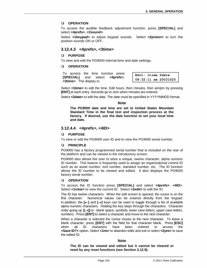
3. GENERAL OPERATION
Page 103 © 2011 Fluke Calibration
OPERATION To access the audible feedback adjustment function, press [SPECIAL] and select <4prefs>, <2sound>. Select <1keypad> to adjust keypad sounds. Select <2piston> to turn the position sounds ON or OFF.
3.12.4.3 <4prefs>, <3time> PURPOSE To view and edit the PG9000 internal time and date settings.
OPERATION
To access the time function press [SPECIAL] and select <4prefs>, <3time>. The display is:
Edit: 1time 2date 08:32:11 am 20031025
Select <1time> to edit the time. Edit hours, then minutes, then am/pm by pressing [ENT] at each entry. Seconds go to zero when minutes are entered. Select <2date> to edit the date. The date must be specified in YYYYMMDD format.
Note The PG9000 date and time are set to United States Mountain Standard Time in the final test and inspection process at the factory. If desired, use the date function to set your local time and date.
3.12.4.4 <4prefs>, <4ID> PURPOSE To view or edit the PG9000 user ID and to view the PG9000 serial number.
PRINCIPLE PG9000 has a factory programmed serial number that is included on the rear of the platform and can be viewed in the introductory screen. PG9000 also allows the user to store a unique, twelve character, alpha numeric ID number. This feature is frequently used to assign an organizational control ID such as an asset number, tool number, standard number, etc. The ID function allows the ID number to be viewed and edited. It also displays the PG9000 factory serial number.
OPERATION To access the ID function press [SPECIAL] and select <4prefs>, <4ID>. Select <1view> to view the current ID. Select <2edit> to edit the ID. The ID has twelve characters. When the edit screen is opened, the cursor is on the first character. Numerical values can be entered directly from the keypad. In addition, the [←] and [→] keys can be used to toggle through a list of available alpha numeric characters. Holding the key steps through the characters. Character order going up ([→]) is: blank space, symbols, lower case letters, upper case letters, numbers. Press [ENT] to select a character and move to the next character. When a character is selected the cursor moves to the next character. To leave a blank character, press [ENT] with the field for that character blank. Press [ESC] when all ID characters have been entered to access the <Save ID?> option. Select <1no> to abandon edits and exit or select <2yes> to save the edited ID.
Note The ID can be viewed and edited but it cannot be cleared or reset by any reset functions (see Section 3.12.9).

PG9602™ OPERATION AND MAINTENANCE MANUAL
© 2011 Fluke Calibration Page 104
3.12.4.5 <4prefs>, <5level> PURPOSE This is the user access level restrictions. Allow the operator to set user protection levels that restrict access to certain functions, and to create or edit the password required for changing User Levels.
PRINCIPLE The PG Terminal provides access to all PG9000 user defined data, settings and functions which include the metrological calibration data. Inadvertent, uninformed or unauthorized altering or deleting of data, settings and functions could require extensive reconfiguration by the user and might cause invalid readings. For these reasons, depending upon the application in which PG9000 is being used, it may be desirable to restrict access to certain functions. The USER LEVEL function provides a means of restricting access to certain functions. Four different levels of security are available: none, low, medium and high. Access to changing security levels can be left open, or be protected by a password so that security levels can be used as a convenient way to avoid accidental changing of data or as a secured means of preventing tampering with PG9000 settings. At a minimum it is recommended to operate at a “Low” access restriction as this will prevent inadvertent edits to the key metrological data. The security levels are structured to support typical operating environments as follows:
None This level is intended for use only by the system manager and/or calibration facility. It allows access and editing in all areas including critical metrological information and other settings that affect measurement integrity.
Low Low security is designed to protect the core specific metrological information and system diagnostic and maintenance functions of the system against accidental alteration. It is intended for an advanced operator performing many different tasks. Low security is the default User Level setting.
Medium Medium security is designed to protect specific metrological information in the system and to ensure that PG9000 is operated using consistent operational parameters.
High High security protects all operating parameters. It is intended to minimize operator choices (e.g., to perform repeated identical tests under consistent conditions).
Caution • PG9000 is delivered with the security level set to low to
avoid inadvertent altering of critical internal settings but with unrestricted access to changing security level setting. It is recommended that the low security level be maintained at all times and password protection be implemented if control over setting of security levels is desired.
• If there is a risk of unauthorized changing of the security level, changing authority should be password protected (see OPERATION of this section).
• The High security level disables remote communications and returns an error message (“ERROR”) to all remote commands. All other security levels have NO effect on remote communications.
The security levels are structured to support typical levels of operation. Specifically, the security levels prevent execution of the functions in Table 17 marked by “•”:

3. GENERAL OPERATION
Page 105 © 2011 Fluke Calibration
Table 17. Security Levels - Functions NOT Executed Per Function/Level
FUNCTION LOW MEDIUM HIGH
[P-C] •
[UNIT] •
[MODE] •
[SYSTEM] •
[AMBIENT] •
[HEAD] • •
[ROTATE] •
[GEN] •
[RES] (change setting) • •
[P OR M] • •
[SETUP], <1select> • •
[SETUP], <2view> •
[SETUP], <3edit> • •
[SPECIAL], <1PC/MS>, <any selection>, <1view> •
[SPECIAL], <1PC/MS>, <any selection>, <2edit> • • •
[SPECIAL], <1PC/MS>, <any selection>, <3add> • • •
[SPECIAL], <1PC/MS>, <any selection>, <4delete> • • •
[SPECIAL], <1PC/MS>, <1PC>, <5select> •
[SPECIAL], <1PC/MS>, <2mass set>, <5select> • •
[SPECIAL], <1PC/MS>, <2mass bell>, <5select> • •
[SPECIAL], <2presU> • •
[SPECIAL], <3head> • •
[SPECIAL], <4prefs> • •
[SPECIAL], <4prefs>, <3time> (make changes) • • •
[SPECIAL], <4prefs>, <4ID>, <2edit> • • •
[SPECIAL], <6remote> (access) •
[SPECIAL], <6remote> (make changes) • •
[SPECIAL], <5prefs>, <3time> (make changes) • • •
[SPECIAL], <6gl> (access) • • •
[SPECIAL], <7cal>, (access) •
[SPECIAL], <7cal>, <any selection except 5Pposition>, <2cal> • • •
[SPEICAL], <8AMH>, <any selection> • •
[SPECIAL], <9reset> • •
[SPECIAL], <9reset>, <1sets> • • •
[SPECIAL], <9reset>, <3com> • • •
[SPECIAL], <9reset>, <4cal> • • •
[SPECIAL], <9reset>, <5setups> • • •
[SPECIAL], <9reset>, <6all> • • •
Remote communications disabled •

PG9602™ OPERATION AND MAINTENANCE MANUAL
© 2011 Fluke Calibration Page 106
OPERATION
Note PG9000 is delivered with NO active password so access to the User Level menu is open. The User Level is set to <2Low>. User Levels can be changed freely until a password has been created. Reset functions (see Section 3.12.9) do not affect the password setting.
To access the User Level function, press [SPECIAL] and select <2level>.
If no password yet exists or if the correct password has been entered, the display is:
1change user level 2edit password
Selecting <1change user level> brings up the restriction menu:
Restriction: 1none 2low 3medium 4high
You can then select the current restriction level, or press [ESC] to return to the main run screen.
Selecting <2edit password> displays the user password and allows it to be edited. Passwords can be up to six numbers in length and cannot start with a zero.
Password: pppppp 0 disables password
If 0 is entered as the password value, then the password is made inactive and a password will NOT be required to access the User Level menu. This is the factory default with a security level of <2low>.
Caution Once a password has been entered, the User Level cannot be changed without reentering the password.
If there is an active password, the PG9000 password entry screen appears.
PG9000 NS nnn-xx Password: pppppp
The user must enter the user defined password or the factory secondary password to proceed. When a password is entered correctly, operation proceeds to the <1change user level 2edit password> screen. The first field, <nnnn>, is the serial number of PG9000, followed by a second field, <xx>. That counts the number of times that a secondary password has been used. This second field increments each time a secondary password is used. The third field, <pppppp>, is for standard password entry. The factory secondary password is available in case the user’s password has been misplaced or forgotten. It can be obtained by contacting a Fluke Calibration Authorized Service Provider. The factory secondary password is different for all PG9000’s and changes each time it is used.
3.12.5 <5remote> PURPOSE To configure the PG9000 COM1, COM2, COM3, COM4 and IEEE-488 communication ports. To test COM1, COM2, COM3 and COM4 communications.
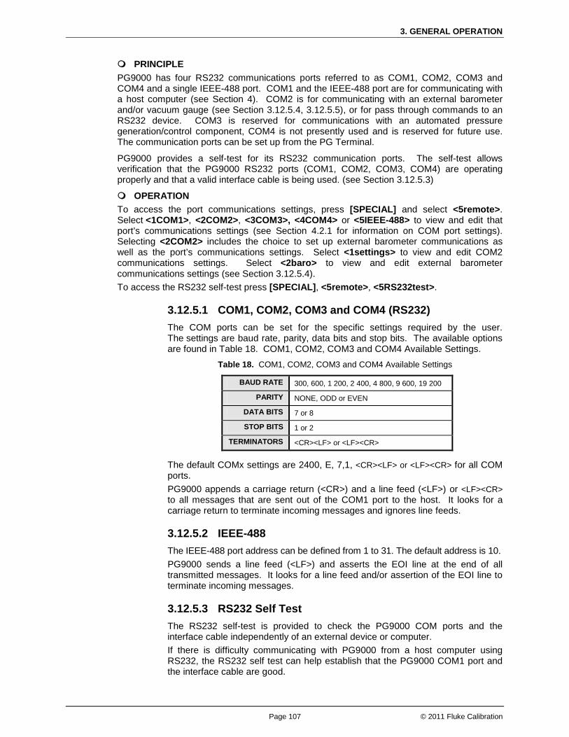
3. GENERAL OPERATION
Page 107 © 2011 Fluke Calibration
PRINCIPLE PG9000 has four RS232 communications ports referred to as COM1, COM2, COM3 and COM4 and a single IEEE-488 port. COM1 and the IEEE-488 port are for communicating with a host computer (see Section 4). COM2 is for communicating with an external barometer and/or vacuum gauge (see Section 3.12.5.4, 3.12.5.5), or for pass through commands to an RS232 device. COM3 is reserved for communications with an automated pressure generation/control component, COM4 is not presently used and is reserved for future use. The communication ports can be set up from the PG Terminal.
PG9000 provides a self-test for its RS232 communication ports. The self-test allows verification that the PG9000 RS232 ports (COM1, COM2, COM3, COM4) are operating properly and that a valid interface cable is being used. (see Section 3.12.5.3)
OPERATION To access the port communications settings, press [SPECIAL] and select <5remote>. Select <1COM1>, <2COM2>, <3COM3>, <4COM4> or <5IEEE-488> to view and edit that port’s communications settings (see Section 4.2.1 for information on COM port settings). Selecting <2COM2> includes the choice to set up external barometer communications as well as the port’s communications settings. Select <1settings> to view and edit COM2 communications settings. Select <2baro> to view and edit external barometer communications settings (see Section 3.12.5.4). To access the RS232 self-test press [SPECIAL], <5remote>, <5RS232test>.
3.12.5.1 COM1, COM2, COM3 and COM4 (RS232) The COM ports can be set for the specific settings required by the user. The settings are baud rate, parity, data bits and stop bits. The available options are found in Table 18. COM1, COM2, COM3 and COM4 Available Settings.
Table 18. COM1, COM2, COM3 and COM4 Available Settings
BAUD RATE 300, 600, 1 200, 2 400, 4 800, 9 600, 19 200
PARITY NONE, ODD or EVEN
DATA BITS 7 or 8
STOP BITS 1 or 2
TERMINATORS <CR><LF> or <LF><CR>
The default COMx settings are 2400, E, 7,1, <CR><LF> or <LF><CR> for all COM ports. PG9000 appends a carriage return (<CR>) and a line feed (<LF>) or <LF><CR> to all messages that are sent out of the COM1 port to the host. It looks for a carriage return to terminate incoming messages and ignores line feeds.
3.12.5.2 IEEE-488 The IEEE-488 port address can be defined from 1 to 31. The default address is 10. PG9000 sends a line feed (<LF>) and asserts the EOI line at the end of all transmitted messages. It looks for a line feed and/or assertion of the EOI line to terminate incoming messages.
3.12.5.3 RS232 Self Test The RS232 self-test is provided to check the PG9000 COM ports and the interface cable independently of an external device or computer. If there is difficulty communicating with PG9000 from a host computer using RS232, the RS232 self test can help establish that the PG9000 COM1 port and the interface cable are good.

PG9602™ OPERATION AND MAINTENANCE MANUAL
© 2011 Fluke Calibration Page 108
To run a self test of a pair of RS232 ports (COM1 and COM2, COM1 and COM3 or COM1 and COM4), press [SPECIAL] and select <5remote>, <5RS232test>. Then select <1COM2> to test COM1 and COM2 or <2COM3> to test COM1 and COM3 or <3COM4> to test COM1 and COM4. The display prompts you to connect COM1 to COM2, COM1 to COM3 or COM1 and COM4 using a standard pin-to-pin DB-9F to DB-9M RS232 cable (see Section 4.2.1). Once the cable has been installed, press [ENT] to run the self-test. The test is first executed in the COM1→COM2/3/4 direction and then in the COM2/3/4→COM1 direction. If the COM1→COM2 (or COM3/4) test passes: <PASSED> displays briefly and the test proceeds to COM2/3/4 →COM1. If COM2/3/4→COM1 passes: <PASSED> is displayed briefly followed by the conclusion, <PG9000 RS232 test has PASSED>. If a test fails: Execution is suspended until [ENT] is pressed.
Note The PG9000 RS232 test can fail for two reasons: 1. The RS232 cable being used is incorrect (see Section 4.2.1, for
information on the correct cable). An incorrect or faulty cable will fail on all of the ports when testing.
2. One of the COM ports is defective. The reason for failed communications is almost always a cable or incorrect RS232 interface settings. Be sure that these are correct before concluding that a COM port is defective.
3.12.5.4 External Barometer (RPM) Communications (COM2) PURPOSE To set up communications with an external barometer from which PG9000 will read the value of atmospheric pressure and use it for internal calculations. The external device is also used for reading the static pressure when PG9000 is used in differential mode (see Section 3.10.4.1).
Note The source of the values of atmospheric pressure used by PG9000 in its internal calculations is determined by the AtmP setting in the current SETUP file (see Section 3.11). Setting up communications with an external barometer does NOT set PG9000 to utilize the external barometer.
PRINCIPLE PG9000 uses atmospheric pressure values in its calculations of defined pressure (see Section 7.2). The source of the value is determined by the AtmP setting in the current SETUP file (see Section 3.10). One of the possible sources is COM2, which allows an external barometer, connected to PG9000’s COM2 RS232 port to be read automatically to obtain the atmospheric pressure values that are used. In order to communicate with an the external barometer PG9000’s COM2 must be properly set up. This setup occurs by pressing [SPECIAL] and selecting <5remote>, <2COM2>, <2baro>.
OPERATION To configure PG9000’s COM2 port to communicate with an external barometer, press [SPECIAL] and select <5remote>, <2COM2>, <2baro>. Select <1RPMx> if the external barometer is a Fluke Calibration (DH Instruments) RPM. Select <2user> to set up communications with a barometer other than a DH Instruments RPM.

3. GENERAL OPERATION
Page 109 © 2011 Fluke Calibration
Note For a remote barometer to be able to be used for automated atmospheric pressure readings on PG9000 COM2, the following requirements apply to the remote barometer’s communications: • Replies to a request to send string within 2 seconds. • Accepts <CR, LF> terminators. • Supplies <CR> or <CR, LF> terminators. • Request to send string must be printable alphanumeric (no control modes or nulls).
Setting Up for User Barometer Communications:
After pressing [SPECIAL] and selecting <5remote>, <2COM2>, <2baro>, <2user>, the display is:
COM2 meas req string
The string value is entered on the second line. It may have up to 20 characters. When the string screen is opened, the cursor is on the first character. Numerical values can be entered directly from the keypad. In addition, the [←] and [→] keys can be used to toggle through a list of available alpha numeric characters. Holding the key steps through the characters. Character order going up ([→]) is: blank space, symbols, lower case letters, upper case letters, numbers. Press [ENT] to select a character and move to the next character. When a character is selected the cursor moves to the next character. To leave a character blank, press [ENT] with the field for that character blank. After the last character has been entered, press [ESC]. This causes a <Save edits?> screen to appear. Select <2yes> to save the edited string and move to the next screen. Select <1no> abandon the edits. Also, if [ENT] is pressed on the 20th character, the string is saved automatically and operation advances to the next screen.
Note The external barometer parameters including the communication string can also be set by remote command, which is more convenient than front panel entry (see Section 4.3.4.2, “UDD” command).
After the string value has been entered the display is:
Reply conv coef: 1.000000 Pa/unit
<conv coef> is the conversion coefficient that PG9000 will use to convert readings from the external barometer to the pressure unit of measure Pascal (Pa). If the readings from the external barometer are NOT Pascal, edit the conversion coefficient value as needed to convert the readings to Pascal.
When the conversion coefficient is entered the next setup screen is opened. The display is:
Leading characters to Strip: 0
This entry specifies the leading characters in the return string that precede the numerical value of the pressure. PG9000 only works with numeric values, if there are non-numeric characters proceeding the barometric pressure value, these need to be stripped. PG9000 will strip the specified number of characters from the front of the return string and assume that the next character is the first number defining the current value of atmospheric pressure. To verify whether external barometer communications have been set up properly, select a SETUP file that specifies COM2 as the source for AtmP (see Section 3.11) and verify that communications with the external barometer are achieved. Then view current barometer readings in the AMBIENT run screen (see Section 3.10.6)

PG9602™ OPERATION AND MAINTENANCE MANUAL
© 2011 Fluke Calibration Page 110
and verify that the readings are correct. Note that a fluid head correction should be set if the external barometer is not at the PG9000 reference level. This correction may cause the reading of the external barometer and the value of ambient pressure indicated by the PG9000 to not be identical (see Section 3.12.3.3).
Note For communications with an external barometer on COM2 to be established properly, the inquiry string to send to the barometer must be defined following this section and the PG9000 COM2 port and barometer COM port must have the same communications settings. Press [SPECIAL] and select <5remote>, <2COM2>, <1settings> to set up PG9000 COM2 communications settings. When unable to establish communications between COM2 and the external barometer, consider using the PG9000 RS232 self test to verify COM2 operation (see Section 3.12.5.3). If both a barometer and a vacuum gauge are connected, the barometer must be an RPM3 or RPM4 and must always be the first device connected to the PG9000 Platform COM2.
3.12.5.5 External Vacuum Gauge Communications (COM2) PURPOSE To configure communications with an external vacuum gauge from which PG9000 will read the value of reference vacuum under the bell jar used in the calculation of absolute pressure in absolute by vacuum measurement mode (see Section 3.10.4).
Note The source of the value of vacuum pressure used by PG9000 in its internal calculations is determined by the Vac setting in the current SETUP file (see Section 3.11. Configuring communications with an external vacuum gauge does NOT set PG9000 to utilize the external vacuum gauge.
PRINCIPLE PG9000 measures the reference vacuum under the bell jar in its calculation of the pressure defined by the PG in absolute by vacuum measurement mode (see Section 7.2). The source of the value is determined by the Vac setting in the current SETUP file (see Section 3.11). The standard source of this value is COM2, which allows an vacuum gauge connected to PG9000’s COM2 RS232 port to be read automatically to obtain the reference vacuum values that are used. In order to communicate with the external vacuum gauge, PG9000’s COM2 must be properly set up. This setup occurs by pressing [SPECIAL] and selecting <5remote>, <2COM2>, <3vac>.
Note If a Fluke Calibration (DH Instruments) RPM3 or RPM4 is being used on COM2 for external measurement of barometric pressure, the vacuum gauge may be connected to COM2 of the RPM. In this case, COM2 of the RPM barometer must be configured with the same communication settings as the external vacuum gauge. If both a barometer and a vacuum gauge are connected, the barometer must always be the first device connected to the PG9000 Platform COM2.

3. GENERAL OPERATION
Page 111 © 2011 Fluke Calibration
OPERATION To set up or verify PG9000’s COM2 port to communicate with an external vacuum gauge, press [SPECIAL] and select <5remote>, <2COM2>, <3vac>. Select <1RPMx> if the external vacuum gauge is a DH Instruments RPM. Select <2user> to set up communications with a vacuum gauge other than a DH Instruments RPM. Select <3dflts> to set COM2 settings, measurement request string and conversion coefficient to support the standard vacuum gauge supplied with the PG9000 vacuum reference hardware.
Note Setting Up for User Vacuum Gauge Communications
For an external vacuum gauge to be able to be used for automated reference vacuum readings on PG7601 COM2 or a DH Instruments RPM’s COM2, the following requirements apply to the remote vacuum gauge’s communications: • Replies to a request to send string within 2 seconds. • Accepts <CR, LF> terminators. • Supplies <CR> or <CR, LF> terminators. • Request to send string must be printable alphanumeric
(no control modes or nulls).
After pressing [SPECIAL] and selecting <5remote>, <2COM2>, <3vac>, <2user>, the display is:
COM2 meas req string
The measurement request string value is entered on the second line. It may have up to 20 characters. When the string screen is opened, the cursor is on the first character. Numerical values can be entered directly from the keypad. In addition, the [←] and [→] keys can be used to toggle through a list of available alpha numeric characters. Holding the key steps through the characters. Character order going up ([→]) is: blank space, symbols, lower case letters, upper case letters, numbers. Press [ENT] to select a character and move to the next character. When a character is selected the cursor moves to the next character. To leave a character blank, press [ENT] with the field for that character blank. After the last character has been entered, press [ESC]. This causes a <Save edits?> screen to appear. Select <2yes> to save the edited string and move to the next screen. Select <1no> abandon the edits. Also, if [ENT] is pressed on the 20th character, the string is saved automatically and operation advances to the next screen.
Note The external vacuum gauge parameters including the communication string can also be set by remote command which is more convenient than front panel entry (see Section 4.3.4.2, “UDV” command). By default the external vacuum gauge parameters are preset to match the standard external vacuum gauge supplied with the PG9000 vacuum reference hardware.
After the string value has been entered the display is:
Reply conv coef: 1.000000 Pa/unit
<conv coef> is the conversion coefficient that PG9000 will use to convert readings from the external vacuum gauge to the pressure unit of measure Pascal [Pa]. If the readings from the external vacuum gauge are NOT Pascal, edit the conversion coefficient value as needed to convert the readings to Pascal.
When the conversion coefficient is entered the next setup screen is opened. The display is:
Leading characters to Strip: 0
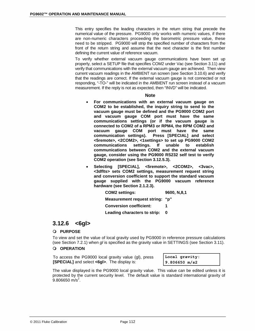
PG9602™ OPERATION AND MAINTENANCE MANUAL
© 2011 Fluke Calibration Page 112
This entry specifies the leading characters in the return string that precede the numerical value of the pressure. PG9000 only works with numeric values, if there are non-numeric characters proceeding the barometric pressure value, these need to be stripped. PG9000 will strip the specified number of characters from the front of the return string and assume that the next character is the first number defining the current value of reference vacuum. To verify whether external vacuum gauge communications have been set up properly, select a SETUP file that specifies COM2 under Vac (see Section 3.11) and verify that communications with the external vacuum gauge are achieved. Then view current vacuum readings in the AMBIENT run screen (see Section 3.10.6) and verify that the readings are correct. If the external vacuum gauge is not connected or not responding, “-TO-” will be indicated in the AMBIENT run screen instead of a vacuum measurement. If the reply is not as expected, then “INVD” will be indicated.
Note • For communications with an external vacuum gauge on
COM2 to be established, the inquiry string to send to the vacuum gauge must be defined and the PG9000 COM2 port and vacuum gauge COM port must have the same communications settings (or if the vacuum gauge is connected to COM2 of a RPM3 or RPM4, the RPM COM2 and vacuum gauge COM port must have the same communication settings). Press [SPECIAL] and select <5remote>, <2COM2>, <1settings> to set up PG9000 COM2 communications settings. If unable to establish communications between COM2 and the external vacuum gauge, consider using the PG9000 RS232 self test to verify COM2 operation (see Section 3.12.5.3).
• Selecting [SPECIAL], <5remote>, <2COM2>, <3vac>, <3dflts> sets COM2 settings, measurement request string and conversion coefficient to support the standard vacuum gauge supplied with the PG9000 vacuum reference hardware (see Section 2.1.2.3).
COM2 settings: 9600, N,8,1 Measurement request string: “p” Conversion coefficient: 1 Leading characters to strip: 0
3.12.6 <6gl> PURPOSE To view and set the value of local gravity used by PG9000 in reference pressure calculations (see Section 7.2.1) when gl is specified as the gravity value in SETTINGS (see Section 3.11). OPERATION
To access the PG9000 local gravity value (gl), press [SPECIAL] and select <6gl>. The display is:
Local gravity: 9.806650 m/s2
The value displayed is the PG9000 local gravity value. This value can be edited unless it is protected by the current security level. The default value is standard international gravity of 9.806650 m/s2.
3. GENERAL OPERATION
Page 113 © 2011 Fluke Calibration
Note The local gravity (gl) value may or may not be used by PG9000 in its calculations of defined pressure. Whether gl or another value, such as normal gravity, is used is determined by the active SETUP file selection (see Section 3.11), not by what is entered by pressing [SPECIAL] and selecting <6gl>.
3.12.7 <7cal> PURPOSE To view or edit the calibration coefficients for PG9000’s internal sensors and measurement systems including:
Barometric pressure Ambient relative humidity Ambient temperature Piston-cylinder module temperature Vacuum Piston position Piston rotation rate
Note In normal operation, the measurements made by PG9000s internal sensors can be viewed in the SYSTEM and AMBIENT run screens by pressing [SYSTEM] or [AMBIENT] (see Sections 3.10.5 and 3.10.6).
PRINCIPLE/OPERATION PG9000 internal sensor calibration functions are considered part of PG9000 maintenance and are covered in the maintenance section of this manual (see Section 5).
3.12.8 <8AMH> PURPOSE Control the optional AMH system and to view its status (see Section 3.7).
PRINCIPLE An optional automated mass handling system is available for PG9000 Platforms. AMH-100-VAC operates in either atmospheric reference (gauge or absolute by ATM) or vacuum reference (absolute by vac or differential) modes (see Section 3.10.4). Operation of the AMH is integrated into PG9000 Platform operation so that mass handling occurs automatically when required. The PG9000 commands the operation of the AMH. [SPECIAL], <8AMH> accesses functions to view the current mass loading status, load all masses, unloaded all masses and load specific masses.
OPERATION To access the AMH status and control functions, an AMH must already be initialized by selecting an AMH type mass set (see Section 3.12.1.10). To access the AMH status and control functions, press [SPECIAL], <8AMH>. Select <1status> for a display of the current loaded/not loaded status of AMH masses (the indication is the same as the discreet control function screen in Section 3.12.8.2). Select <2control> to control AMH directly:
<1up/down> to move the AMH mass actuator up or down (see Section 3.12.8.1). <2discreet> to specify the masses to be loaded and unloaded (see Section 3.12.8.2).
<3loadall> to load all the AMH masses onto the piston (see Section 3.12.8.3). <4unloadall> to unload all the AMH masses from the piston (see Section 3.12.8.4).

PG9602™ OPERATION AND MAINTENANCE MANUAL
© 2011 Fluke Calibration Page 114
3.12.8.1 <2control>, <1up/down> PURPOSE To move the AMH mass load to the up or down position (see Section 3.7.1).
OPERATION To move the mass handler actuator to the up and down positions, press [SPECIAL], <8AMH>, <1up/down>. The display indicates the current position. Press [ENT] to change the position. This control does not actually change the state of the binary mass pins nor the main mass column positions.
Warning Do not put fingers or anything else under the AMH trim mass tray. When the mass load is lowered, it can pinch or crush anything under it.
3.12.8.2 <2control>, <2discreet> PURPOSE To load and unload specific AMH masses.
OPERATION To load and unload specific AMH masses, press [SPECIAL], <8AMH>, <2control>, <2discreet>.
The display is: 1* 2 4* 8 16 32 64 Main:1
The <1>, <2>, <4>, <8>, <16>, <32> and <64> indicate the 0.1, 0.2, 0.4, 0.8, 1.6, 3.2 and 6.4 kg binary tube masses. <*> indicates that the mass is loaded. Move the cursor to a mass and press [+/-] or [.] to change its status. <Main:> indicates the number of main masses that are loaded. Edit this number to the desired value. If any condition in the discreet display is changed the bottom right of the display changes to <ENT loads>. Pressing the [ENT] key to causes AMH to operate to load the new mass configuration. Press [ESC] to return to the AMH menu with no change in mass load.
Warning Do not put fingers or anything else under the AMH trim mass tray. When the mass load is lowered, it can pinch or crush anything under it.
3.12.8.3 <2control>, <3loadall> PURPOSE To clear the AMH and cause all the masses in the AMH mass set to be loaded onto the piston. The function is used to remove all the masses from the mass handler and prepare it to be removed from or installed onto the PG9000 platform.
OPERATION To load all AMH masses, press [SPECIAL], <8AMH>, <3loadall>. Confirm the load all instruction and AMH proceeds to lower all the masses onto the piston.
Warning
Do not put fingers or anything else under the AMH trim mass tray. When the mass load is lowered, it can pinch or crush anything under it.

3. GENERAL OPERATION
Page 115 © 2011 Fluke Calibration
3.12.8.4 <2control>, <4unloadall> PURPOSE To clear the AMH and cause all the masses in the AMH mass set to be unloaded from the piston (removes them from the piston and retains in the AMH).
OPERATION To unload all AMH masses, press [SPECIAL], <8AMH>, <4unloadall>. Confirm the unload all instruction and AMH proceeds to raise all the masses off the piston. When the mass handler lowers, the bell and mass lifting shaft are still loaded on the piston.
Warning Do not put fingers or anything else under the AMH trim mass tray. When the mass load is lowered, it can pinch or crush anything under it.
3.12.9 <9reset> PURPOSE To reset various PG9000 settings to default or factory values. PG9000 stores its user definable settings in non-volatile memory. The reset menu allows the user to selectively or completely reset these settings to factory defaults. Resets clear settings that the user may have made, and should be used only to restore the PG9000 to a known state. PG9000 will go through its reboot routine after any type of reset is executed.
OPERATION
To access the reset choices press [SPECIAL] and select <9reset>. The display is:
1sets 2units 3com 4cal 5setups 6all
Select the desired reset. After confirmation, the reset occurs. A reset always puts PG9000 through its start up routine as if power had been turned OFF and back ON. See Sections 3.11.9.1 through 3.11.9.6 for detailed information on the specific reset choices.
Caution Reset functions change user settings that affect pressure measurement. If not used properly, resetting can cause out of tolerance measurements. Reset functions should only be used by qualified personnel with reference to this manual for information on the reset functions.
3.12.9.1 <9reset>, <1sets> PURPOSE / OPERATION To access Reset - Sets, press [SPECIAL] and select <1reset>, <1sets>. Reset - Sets clears and sets to default the user settings. This is a low level reset and is considered as a safe means to restore the PG9000 when odd behavior is observed. The reset 1sets includes:
• Pressure unit of measure to pressure unit #1 of [UNIT] (see Section 3.10.3).
• Measurement mode to gauge (see Section 3.10.4). • DUT head height to zero and ATM head height to default (see Sections
3.10.7, 3.12.3.3). • DUT head height units to centimeters (see Section 3.12.3.2). • PISTON head correction ON (see Section 3.12.3.4). • Set up file to #1 (see Section 3.11). • Active piston-cylinder module, mass set and mass loading bell to #1 (first
in list) (see Sections 3.12.1.5, 3.12.1.10, 3.12.1.15).

PG9602™ OPERATION AND MAINTENANCE MANUAL
© 2011 Fluke Calibration Page 116
• Mass loading resolution to 0.01 g (see Section 3.10.10). • Automatic rotation off (see Section 3.10.8). • Automatic rotation pre-decel on (see Section 3.10.8.1). • Automatic pressure generation off (see Section 3.10.9). • Automatic pressure generation controller raise function to OFF (see
Section 3.10.9.2). • Automatic pressure generation controller tolerance to 0.05% of full scale
(see Section 3.10.9.4). • Automatic pressure generation controller refloat function to ON (see
Section 3.10.9.5). • Mode to pressure-to-mass (see Section 3.10.12). • Screen saver to 10 minutes (see Section 3.12.4.1). • PC sounds to ON and keyboard sounds to medium frequency (see
Section 3.12.4.2).
3.12.9.2 <9reset>, <2units> PURPOSE / OPERATION To access Reset - Units, press [SPECIAL] and select <1reset>, <2units>. Reset - Units clears and sets to default all unit of measure functions. This includes:
• [UNIT] pressure unit of measure selections to defaults and active unit to #1 (see Section 3.10.3).
• Sets the user pressure unit coefficient to 1.00/Pa (see Section 3.10.3.1).
3.12.9.3 <9reset>, <3com> OPERATION / PURPOSE To access Reset - Com, press [SPECIAL] and select <1reset>, <3com>. Reset - Com clears and sets to default the PG9000 communications ports (see Section 3.11.5). This includes:
COM1, COM3 and COM4 Baud Rate
Parity Data Bits Stop Bits
Terminating Characters
2400 Even 7 1 <CR>, <LF>
COM2 Baud Rate
Parity Data Bits Stop Bits
Terminating Characters
9600 None 8 1 <CR>, <LF>
IEEE-488 (GPIB) Address
Terminating Characters
10 <CR>, <LF>
COM2 User Barometer Inquiry String and Characters see Section 3.12.5.4 COM2 Vacuum Gauge Inquiry String and Characters see Section 3.12.5.5

3. GENERAL OPERATION
Page 117 © 2011 Fluke Calibration
3.12.9.4 <9reset>, <4cal> OPERATION / PURPOSE
Caution Use caution with this reset as critical calibration data may be altered.
To access Reset - Cal, press [SPECIAL] and select <1reset>, <4cal>. Reset - Cal DOES NOT reset piston-cylinder module, mass set and mass bell files. There is no user available reset for them. Reset - Cal clears and sets to default the user calibration coefficients for PG9000 on-board sensors (see Section 5.2.1). This includes:
Barometric Sensor Adder
Multiplier Calibration Date
0 1 20000101
Humidity Sensor Adder
Multiplier Calibration Date
0 1 20000101
Ambient Temperature Sensor Adder
Multiplier Calibration Date
0 1 20000101
Piston-Cylinder Module Temperature Sensors RZ
Slope Calibration Date
100.000 Ω 0.3896 20000101
Vacuum Gauge Adder
Multiplier Calibration Date
0 1 20000101
Note Reset - Cal has no effect on the reference resistance values used to calibrate PG9000s internal ohmic measurement system (see Section 5.2.1.5) as these are not normal user accessible data.
3.12.9.5 <9reset>, <5setups> To access Reset - Setups, press [SPECIAL] and select <1reset>, <5setups>. Reset - Setups deletes all SETUP files and selects SETUP file #1 as the active SETUP file (see Section 3.11).
3.12.9.6 <9reset>, <6all> OPERATION / PURPOSE To return PG9000 to the original, as delivered, factory condition. To access Reset - All, press [SPECIAL] and select <1reset>, <6all>.
• Performs the functions of the Sets, Units, Cal and Com resets (see Sections 3.12.9.1 to 3.12.9.5).
• User security level to low, but does not affect the User Level password (see Section 3.12.4.5).
• Local gravity to 9.80665 m/s2 (see Section 3.12.6)

PG9602™ OPERATION AND MAINTENANCE MANUAL
© 2011 Fluke Calibration Page 118
Notes

Page 119 © 1998-2010 Fluke Calibration
4. Remote Operation
4.1 Overview Most of the PG9000 Terminal’s front panel functions can also be executed by commands from a remote computer. The host computer can communicate with PG9000 using the COM1 RS232 port or the IEEE-488 port located on the PG9000 Remote Electronics Module (REM) rear panel. The command syntax is the same for either port except when using the IEEE STD. 488.2 Common commands.
4.2 Interfacing Sending a command to PG9000 places it in remote mode. The function keys on the front panel are locked-out, except for the [SYSTEM] and [AMBIENT] keys which still respond to allow the user to change the data displayed. Pressing the [ESC] key returns PG9000 to local mode unless the “REMOTE” command was sent which locks out keypad operation until the “LOCAL” command is sent.
Most remote commands return a reply within 500 ms. The following commands may query external devices connected to PG9000’s COM2 and/or COM3 ports and can take up to 5 to 10 seconds to reply:
“MASS=” (possible communications with an external AMH mass handler) “PGEN=” (requires communications with an external pressure controller) “SETUP=” (possible communications with external barometer or vacuum gauge) “AMHLOAD=” (possible delay while AHM completes the action)
You must wait for this reply before issuing another command to PG9000. This ensures that PG9000 has completed the command. An exception is the use of any of the IEEE STD. 488.2 Common Commands (see Section 4.3.4.1) via the IEEE-488 interface (common commands all start with an asterisk, “*”). The common commands only generate a reply if using the COM1 port or if the query form of the common command is used (command followed by a “?”).
4.2.1 RS232 interface To establish RS232 communications a standard pin-to-pin DB-9F to DB-9M RS232 cable must be used to connect the host COM port to PG9000 COM1. The interface settings of both ports must be the same.
Note PG9000 supports an independent RS232 self-test to verify that the PG9000 RS232 ports are operating correctly and the interface cable being used is valid. Use this self-test to troubleshoot if you are having difficulty establishing communications with any PG9000 COM1 (see Section 3.12.5.3).
4.2.1.1 COM1 The PG9000 COM1 RS232 interface is located on the PG9000 Remote Electronics Module (REM) rear panel. It is a 9-pin female DB-9F connector configured as a DCE device. Data is transmitted out of PG9000 using pin 2, and is received on pin 3. This allows a standard pin-to-pin DB-9M to DB-9F RS232 cable to be used to connect to a DTE host (see Table 19). Handshaking is NOT required or supported. COM1 RS232 commands must be terminated with at least a single carriage return character, while line feed characters are ignored. All RS232 responses from PG9000 are terminated with a carriage return character and a line feed character (either <CR><LF> or <LF><CR> see Section 3.12.5.1).
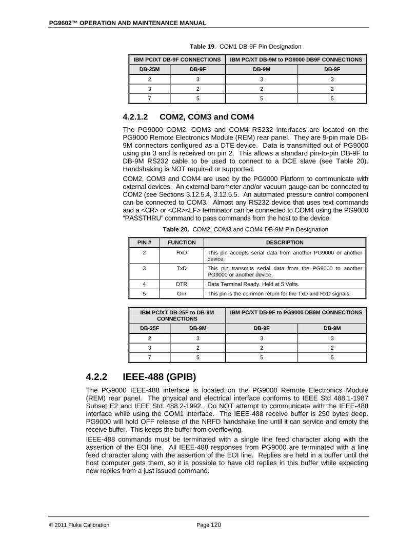
PG9602™ OPERATION AND MAINTENANCE MANUAL
© 2011 Fluke Calibration Page 120
Table 19. COM1 DB-9F Pin Designation
IBM PC/XT DB-9F CONNECTIONS IBM PC/XT DB-9M to PG9000 DB9F CONNECTIONS
DB-25M DB-9F DB-9M DB-9F
2 3 3 3
3 2 2 2
7 5 5 5
4.2.1.2 COM2, COM3 and COM4 The PG9000 COM2, COM3 and COM4 RS232 interfaces are located on the PG9000 Remote Electronics Module (REM) rear panel. They are 9-pin male DB-9M connectors configured as a DTE device. Data is transmitted out of PG9000 using pin 3 and is received on pin 2. This allows a standard pin-to-pin DB-9F to DB-9M RS232 cable to be used to connect to a DCE slave (see Table 20). Handshaking is NOT required or supported. COM2, COM3 and COM4 are used by the PG9000 Platform to communicate with external devices. An external barometer and/or vacuum gauge can be connected to COM2 (see Sections 3.12.5.4, 3.12.5.5. An automated pressure control component can be connected to COM3. Almost any RS232 device that uses text commands and a <CR> or <CR><LF> terminator can be connected to COM4 using the PG9000 “PASSTHRU” command to pass commands from the host to the device.
Table 20. COM2, COM3 and COM4 DB-9M Pin Designation
PIN # FUNCTION DESCRIPTION
2 RxD This pin accepts serial data from another PG9000 or another device.
3 TxD This pin transmits serial data from the PG9000 to another PG9000 or another device.
4 DTR Data Terminal Ready. Held at 5 Volts.
5 Grn This pin is the common return for the TxD and RxD signals.
IBM PC/XT DB-25F to DB-9M CONNECTIONS
IBM PC/XT DB-9F to PG9000 DB9M CONNECTIONS
DB-25F DB-9M DB-9F DB-9M
2 3 3 3
3 2 2 2
7 5 5 5
4.2.2 IEEE-488 (GPIB) The PG9000 IEEE-488 interface is located on the PG9000 Remote Electronics Module (REM) rear panel. The physical and electrical interface conforms to IEEE Std 488.1-1987 Subset E2 and IEEE Std. 488.2-1992. Do NOT attempt to communicate with the IEEE-488 interface while using the COM1 interface. The IEEE-488 receive buffer is 250 bytes deep. PG9000 will hold OFF release of the NRFD handshake line until it can service and empty the receive buffer. This keeps the buffer from overflowing. IEEE-488 commands must be terminated with a single line feed character along with the assertion of the EOI line. All IEEE-488 responses from PG9000 are terminated with a line feed character along with the assertion of the EOI line. Replies are held in a buffer until the host computer gets them, so it is possible to have old replies in this buffer while expecting new replies from a just issued command.
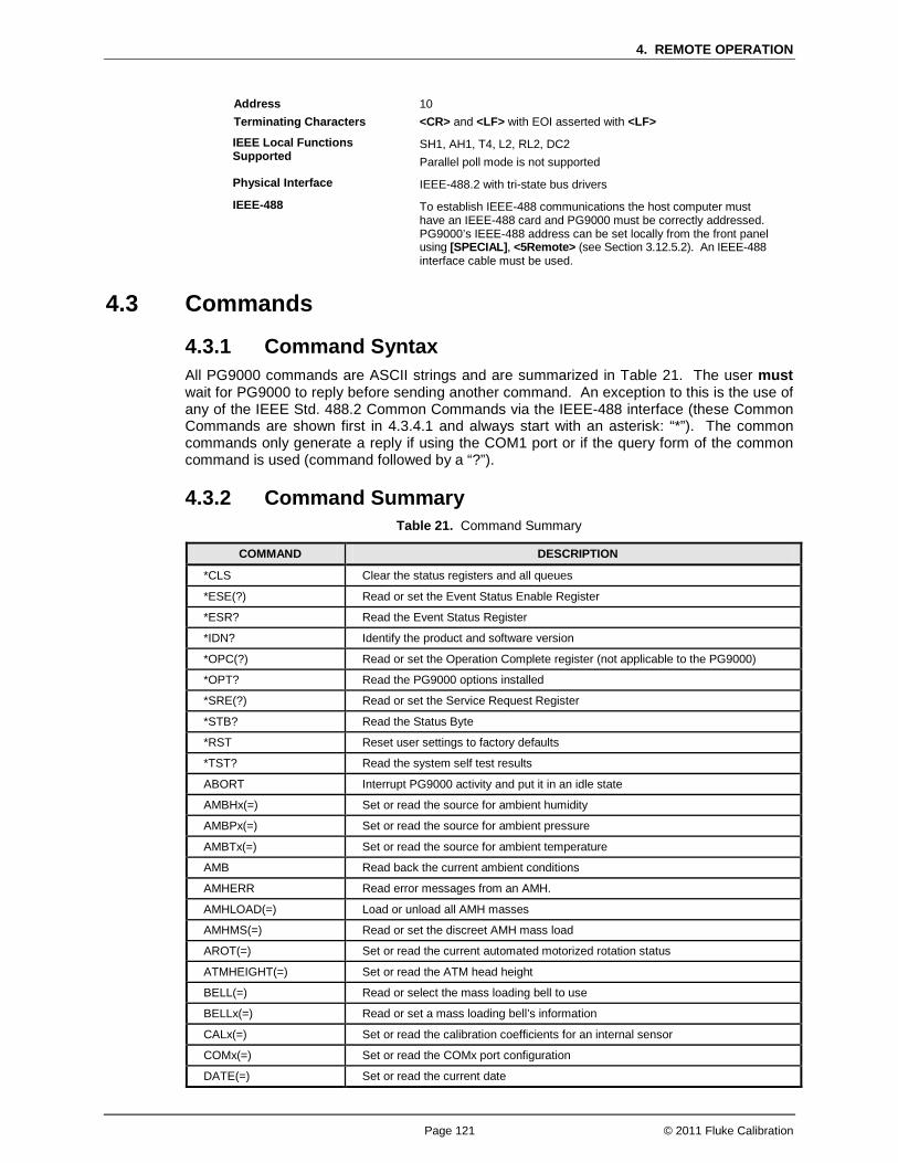
4. REMOTE OPERATION
Page 121 © 2011 Fluke Calibration
Address Terminating Characters
10 <CR> and <LF> with EOI asserted with <LF>
IEEE Local Functions Supported
SH1, AH1, T4, L2, RL2, DC2 Parallel poll mode is not supported
Physical Interface IEEE-488.2 with tri-state bus drivers
IEEE-488 To establish IEEE-488 communications the host computer must have an IEEE-488 card and PG9000 must be correctly addressed. PG9000’s IEEE-488 address can be set locally from the front panel using [SPECIAL], <5Remote> (see Section 3.12.5.2). An IEEE-488 interface cable must be used.
4.3 Commands
4.3.1 Command Syntax All PG9000 commands are ASCII strings and are summarized in Table 21. The user must wait for PG9000 to reply before sending another command. An exception to this is the use of any of the IEEE Std. 488.2 Common Commands via the IEEE-488 interface (these Common Commands are shown first in 4.3.4.1 and always start with an asterisk: “*”). The common commands only generate a reply if using the COM1 port or if the query form of the common command is used (command followed by a “?”).
4.3.2 Command Summary Table 21. Command Summary
COMMAND DESCRIPTION
*CLS Clear the status registers and all queues
*ESE(?) Read or set the Event Status Enable Register
*ESR? Read the Event Status Register
*IDN? Identify the product and software version
*OPC(?) Read or set the Operation Complete register (not applicable to the PG9000)
*OPT? Read the PG9000 options installed
*SRE(?) Read or set the Service Request Register
*STB? Read the Status Byte
*RST Reset user settings to factory defaults
*TST? Read the system self test results
ABORT Interrupt PG9000 activity and put it in an idle state
AMBHx(=) Set or read the source for ambient humidity
AMBPx(=) Set or read the source for ambient pressure
AMBTx(=) Set or read the source for ambient temperature
AMB Read back the current ambient conditions
AMHERR Read error messages from an AMH.
AMHLOAD(=) Load or unload all AMH masses
AMHMS(=) Read or set the discreet AMH mass load
AROT(=) Set or read the current automated motorized rotation status
ATMHEIGHT(=) Set or read the ATM head height
BELL(=) Read or select the mass loading bell to use
BELLx(=) Read or set a mass loading bell’s information
CALx(=) Set or read the calibration coefficients for an internal sensor
COMx(=) Set or read the COMx port configuration
DATE(=) Set or read the current date
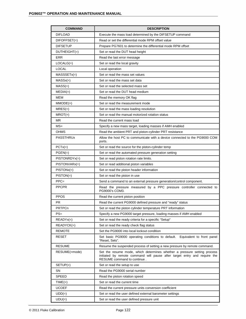
PG9602™ OPERATION AND MAINTENANCE MANUAL
© 2011 Fluke Calibration Page 122
COMMAND DESCRIPTION
DIFLOAD Execute the mass load determined by the DIFSETUP command
DIFOFFSET(=) Read or set the differential mode RPM offset value
DIFSETUP Prepare PG7601 to determine the differential mode RPM offset
DUTHEIGHT(=) Set or read the DUT head height
ERR Read the last error message
LOCALG(=) Set or read the local gravity
LOCAL Local operation
MASSSETx(=) Set or read the mass set values
MASSx(=) Set or read the mass set data
MASS(=) Set or read the selected mass set
MEDIA(=) Set or read the DUT head medium
MEM Read the memory OK flag
MMODE(=) Set or read the measurement mode
MRES(=) Set or read the mass loading resolution
MROT(=) Set or read the manual motorized rotation status
MR Read the current mass load
MS= Specify a new mass target, loading masses if AMH enabled
OHMS Read the ambient PRT and piston-cylinder PRT resistance
PASSTHRUx Allow the host PC to communicate with a device connected to the PG9000 COM ports.
PCTx(=) Set or read the source for the piston-cylinder temp
PGEN(=) Set or read the automated pressure generation setting
PISTONRDYx(=) Set or read piston rotation rate limits.
PISTONVARx(=) Set or read additional piston variables
PISTONx(=) Set or read the piston header information
PISTON(=) Set or read the piston in use
PPC= Send a command to an external pressure generation/control component.
PPCPR Read the pressure measured by a PPC pressure controller connected to PG9000’s COM3.
PPOS Read the current piston position
PR Read the current PG9000 defined pressure and “ready” status
PRTPCn Set or read the piston cylinder temperature PRT information
PS= Specify a new PG9000 target pressure, loading masses if AMH enabled
READYx(=) Set or read the ready criteria for a specific “Setup”
READYCK(=) Set or read the ready check flag status
REMOTE Set the PG9000 into local lockout condition
RESET Set basic PG9000 operating conditions to default. Equivalent to front panel “Reset, Sets”.
RESUME Resume the suspended process of setting a new pressure by remote command.
RESUME(=mode) Set the resume mode, which determines whether a pressure setting process initiated by remote command will pause after target entry and require the RESUME command to continue .
SETUP(=) Set or read the setup to use
SN Read the PG9000 serial number
SPEED Read the piston rotation speed
TIME(=) Set or read the current time
UCOEF Read the current pressure units conversion coefficient
UDD(=) Set or read the user defined external barometer settings
UDU(=) Set or read the user defined pressure unit

4. REMOTE OPERATION
Page 123 © 2011 Fluke Calibration
COMMAND DESCRIPTION
UDV(=) Set or read the user defined external vacuum gauge settings
UL(=) Set or read the upper limit of an external pressure generation/control component.
UNIT(=) Set or read the current pressure unit
VACPx(=) Set or read the source for the vacuum measurement
VAC(=) Set or read the vacuum reference flag
VENT(=) To vent the test pressure to atmosphere if an automated pressure generation/control component is being used for automatic pressure generation.
VER Read version number of the internal software
# Send a command through PG9000 to an external device on COM2
4.3.3 Error Messages The PG9000 always replies to a command. If the command is incorrect or contains invalid data, an error number is returned in the form “ERR# n” where n is an integer number that represents a specific error. This allows for easy error trapping by the host computer. Table 22 is a list of the possible error numbers and the error description for each.
Table 22. Error Messages
REPLY DESCRIPTION
ERR #0 OK
ERR #1 First argument missing or out of range
ERR #2 Second argument missing or out of range
ERR #3 Third argument missing or out of range
ERR #4 Fourth argument missing or out of range
ERR #5 Fifth argument missing or out of range
ERR #6 Sixth argument missing or out of range
ERR #7 Seventh argument missing or out of range
ERR #8 Eighth argument missing or out of range
ERR #9 Unknown command
ERR #10 Motorized rotation recovering from overload
ERR #11 Command missing argument
ERR #12 System overpressured
ERR #13 External RPM or PG9000 not detected
ERR #14 User unit not defined
ERR #15 Range jumper setting invalid
ERR #16 Element not defined
ERR #17 UDD not defined
ERR #18 Command not yet available
ERR #19 Not available with gauge units
ERR #20 Not available with vacuum reference
ERR #21 Internal pointer error
ERR #22 Pressure must be below 20 psia
ERR #23 Option not available or installed
ERR #24 Not available with isolation on
ERR #25 Must be READY set
ERR #26 COM port failed to initialize
ERR #27 Internal device time out error
ERR #28 External device time out error
ERR #29 File not opened

PG9602™ OPERATION AND MAINTENANCE MANUAL
© 2011 Fluke Calibration Page 124
REPLY DESCRIPTION
ERR #30 File end
ERR #35 PG9000 must first be setup for differential mode
ERR #36 Mass load invalid
ERR #37 External device invalid
ERR #38 External device configured incorrectly
ERR #39 External device reply invalid
ERR #40 Not ready
ERR #41 Measurement outside limits
ERR #42 Storage Fault
ERR #43 Storage verification error
4.3.3.1 AMH Errors If the optional AMH is being used, it can generate its own error messages during operation. This usually occurs if the AMH is not properly setup, or has a mechanical failure. The 3rd character of the “PR” query reply will be an ‘E’ to indicate if the AMH has failed to operate as expected. If this occurs the “AMHERR” command may be used to get the specific AMH error message. See Section 3.7.2.8 for more details.
4.3.4 Command Descriptions Each command description gives the full syntax showing usage. Ranges of parameters or parameter types are indicated. There are two types of commands. The Common and Status Commands support IEEE STD 488.2, while the PG9000 commands access all other functions.
4.3.4.1 IEEE Std. 488.2 Common And Status Commands PG9000 supports a set of commands that are common to all instruments conforming to IEEE Std. 488.2 protocol. Though defined by the IEEE-488.2 standard, they also apply to PG9000 RS232 (COM1) communications. These commands make it easy to perform basic functions for any device that supports them. These command also cover the status reporting commands. Refer to Section 4.4 for details on the status registers mentioned in these commands. Query forms of these commands must be followed by a question mark and IEEE-488.2 Common Commands always start with an asterisk (“*”). Unlike the other PG9000 commands, they must have a space instead of an equals sign (“=”) between the command and any arguments. Also unlike the other PG9000 commands, if using the IEEE-488 port, the query form (command is immediately followed by a “?”) must be used to get a reply. If using the COM1 port and the command is not a query, “OK” will be returned.
∗CLS Purpose Clear all of the status and event structures. Syntax “∗CLS” Remarks This program message clears the following evens and status registers:
Standard Byte Register (STB) Standard Event Status Register (ESR) Error Queue AMH error message Pending OPC operations
Example Command: Reply:
“*CLS” “OK” (using COM1. No reply if IEEE-488 port)

4. REMOTE OPERATION
Page 125 © 2011 Fluke Calibration
∗ESE(?) Purpose Read or set the Standard Event Status Enable Register. Syntax “∗ESE n” “∗ESE?” Parameters n: ’0 to 255’ This is the decimal representation of the bit(s) to
enable. To enable the PON and QYE bits, the argument would be 128 + 4 = 132.
Query Reply n (0 to 255) Remarks The Standard Event Status Enable register determines which bits in the standard Event
Status Register are enabled and included in the Status Byte Register (ESB bit), and can assert the SRQ line. The reply is in decimal numeric form.
Example Command: Reply:
“*ESE 132” “OK” (using COM1. No reply if IEEE-488 port)
Command: Reply:
“*ESE?” “132”
∗ESR? Purpose Read the Standard Event Register. Syntax “∗ESR?” Query Reply n (0 to 255) Remarks The Standard Event Register contents are cleared after reading. The reply is in decimal
numeric form. Example Command:
Reply: “*ESR?” “4”
∗IDN? Purpose Identify the PG9000 model, and serial number. Syntax “∗IDN?” Remarks The identification reply is made up of the manufacturer, the model, the serial number
and the software version. Each is separated by a comma. Query Reply The version string. Example Command:
Reply: “*IDN?” “FLUKE, PG9602, 1001, Ver3.00a-Lib:nmcm
∗OPC(?) Purpose Sets the operation complete bit when all operations have completed. Syntax “∗OPC” “∗OPC?” Remarks This Command enables PG9000 to set the OPC bit in the Standard Event Status Register
when it has completed all pending functions. The Query replies with a “1” when all functions are complete. Since PG9000 does not support overlapping commands, this command has no practical use.
Query Reply “0” or “1” Example Command:
Reply: “*OPC” “OK” (using COM1. No reply if IEEE-488 port)
Command: Reply:
“*OPC?” “1”
∗OPT? Purpose Reads the list of installed PG9000 options. Syntax “∗OPT?” Remarks This Query returns any registered option(s) installed in the PG. Each option is
separated by a comma. Query Reply A comma delimited text field of the installed options. Example Command:
Reply: Reply:
“*OPT?” “NONE” (no options installed) “auto rotation” (auto rotation option)
∗RST Purpose Resets the PG9000 settings to factory settings. Syntax “∗RST” Remarks This Command sets the PG9000 settings to factory settings which is equivalent to a
front panel executed [SPECIAL], <5Reset>, 1sets. This does not affect the communications settings.
Example Command: Reply:
“*RST” “OK” (using COM1. No reply if IEEE-488 port)
See Also: 3.12.9.1

PG9602™ OPERATION AND MAINTENANCE MANUAL
© 2011 Fluke Calibration Page 126
∗SRE(?) Purpose Read or set the Service Request Enable Register. Syntax “∗SRE n” “∗SRE?” Parameters n: ’0 to 255’ This is the decimal representation of the bit(s) to enable. To allow the MAV and ESB
bits to assert the SRQ line, the argument would be 32 + 16 = 48. Bit 6 (64) is reserved and cannot be set.
Remarks The Service Request Enable Register determines which bits of the Status Byte can set the MSS bit of the Status Byte and request service by asserting the SRQ line of the IEEE-488 interface.
Query Reply n (0 to 255) Example Command:
Reply: “*SRE 48” “OK” using COM1. No reply if IEEE-488 port)
Command: Reply:
“*SRE?” “48”
∗STB? Purpose Read the Status Byte Register. Syntax “∗STB?” Remarks The Status Byte Register reflects the general status of the PG. The ‘MSS’ bit state is
represented by bit 6. Query Reply n (0 to 255) Example Command:
Reply: “*STB?” “4”
∗TST? Purpose Read the power on self test status. Syntax “∗TST?” Remarks The PG9000 system memory stores the user settings (units, mode, resolution) and
retains them when the unit is shut off. On power up, this memory is checked. If this memory is corrupted, all user settings are reset to default (as if the “∗RST” program message was executed), and the ∗TST query returns a ‘1’. If PG9000 passed the test on power up OR if the ∗TST query was used at least once since the unit was powered up the reply is ‘0’.
Query Reply “0” or “1” Example Command:
Reply: “*TST?” “1”
See Also 3.12.9.1
4.3.4.2 PG9000 Commands # Purpose To send a command through PG9000 to an external device on COM2. Syntax “#ddddd” Default N/A Argument N/A Remarks If PG9000 receives a command from the serial port (COM1) with a “#” as the leading
character, the character is stripped off and the command is sent out the secondary serial port (COM2). The PG9000 will then wait for up to 4 seconds for a reply. Do not attempt to communicate with a device that is currently being used by the PG9000 as a vacuum sensor or barometer.
Example Typical command: Typical reply:
“#*0100P3” “*000114.503”
Error ERR# 27 Device is currently active ERR# 28 Device did not reply within 4 seconds
ABORT Purpose Aborts any active process executing in the PG9000. Syntax “ABORT” Default N/A Argument N/A Remarks The ABORT command places the PG9000 in an Idle state, halting the execution of any
active processes. This includes automated AMH mass loads, auto float and auto rotation operations or any differential mode preparation sequence.
Example Typical command: Typical reply:
“ABORT” “ABORT”
Error None See Also “PS=”, “MS=”, “AROT”, “DIFOFFSET”, “DIFSETUP”

4. REMOTE OPERATION
Page 127 © 2011 Fluke Calibration
AMBHx(=) Purpose Set or read the source for the ambient humidity measurement. Also optionally sets the
USER defined measurement. Syntax “AMBHx=source, meas”
“AMBHx=source” “AMBHx”
Default INTERNAL Argument x: The setup number from 1 to 13. See the SETUP command. Source: The measurement source. This can be INTERNAL, NORMAL
or USER. Meas: The current measurement used. This can only be set if the
source argument is USER. If specified, the limit for this argument is 0 to 100 %.
Remarks PG9000 has an on-board humidity sensor that can be used as the source of ambient humidity values in calculations. You may also request that another source be used for this measurement. The measurement source can be the internal sensor, a user defined fixed value, or a normal value. The SETUP function allows 13 separate source configurations for the various SETUP variables to be saved in 12 files. The SETUP command selects which of the files to make active. Setup number 1 is restricted as INTERNAL only to serve as a manufacturer’s fixed Setup, and cannot be changed.
Example Typical command: Typical reply:
“AMBH2=USER,50” “USER, 50 %”
Typical command: Typical reply:
“AMBH9=INTERNAL” “INTERNAL, 25 %”
Error See 9.3.2 Error Messages ERR #1
ERR #2 ERR #3
The setup number x is invalid The source argument is invalid The meas argument is invalid
See Also 1.2.1.3, 3.1, 3.10.6, 3.11, “SETUP”
AMBPx(=) Purpose Set or read the source for the ambient pressure measurement. Also optionally sets the
USER defined measurement. Syntax “AMBPx=source, meas”
“AMBPx=source” “AMBPx”
Default INTERNAL Argument x: The setup number from 1 to 13. See the SETUP command. Source: The measurement source. This can be INTERNAL, NORMAL,
USER, RPM or the user defined barometer “label”. Meas: The current measurement used in kPaa. This can only be set if
the source argument is USER. If specified, the limit for this argument is 70 to 110 kPaa.
Remarks PG9000 has an internal atmospheric pressure sensor that can be used as the source of ambient pressure values in calculations. You may also request that another source be used for this measurement. The measurement source can be the internal sensor, a user defined fixed value, the normal value, an external RPM, or a user defined external barometer. If an external RPM or a user defined external barometer is chosen, you must setup the COM2 port to the proper settings. It is also advised to set this up prior to selecting the setup to make the device active. If you specify “RPM” or the user defined barometer “label” , then all other barometer source setups set to “RPM” or the user defined barometer will change to this source, as it is a global selection. The SETUP function allows 13 separate source configurations for the various SETUP variables to be saved in 12 files. The SETUP command selects which of the files to make active. Setup number 1 is the manufacturer’s preferred Setup, and cannot be changed. The meas argument is used to allow the user to define a fixed value if the source is set to USER. The reply will always include the source and the meas fields.
Example Typical command: Typical reply:
“AMBP2=USER,101.90” “USER, 101.90 kPaa”
Typical command: Typical reply:
“AMBP9=INTERNAL” “INTERNAL, 98.234kPaa”
Error See the “UDU” command See the “COM2” command See 9.3.2 Error Messages
ERR #1 ERR #2 ERR #3
The setup number x is invalid The source argument is invalid The meas argument is invalid
See Also 1.2.1.3, 3.1, 3.10.6, 3.11, “SETUP”, “UDU”, “COM2”

PG9602™ OPERATION AND MAINTENANCE MANUAL
© 2011 Fluke Calibration Page 128
AMBTx(=) Purpose Set or read the source for the ambient temperature measurement. Also optionally sets
the USER defined measurement. Syntax “AMBTx=source, meas”
“AMBTx=source” “AMBTx”
Default INTERNAL Argument x: The setup number from 1 to 13. See the SETUP command. Source: The measurement source. This can be INTERNAL, NORMAL
or USER. Meas: The current measurement used is degrees Celsius. This can
only be set if the source argument is USER. If specified, the limit for this argument is 0 to 50 ° C.
Remarks PG9000 has an internal ambient temperature sensor that can be used as the source of ambient temperature values in calculations. You may also request that another source be used for this measurement. The measurement source can be the internal sensor, a user defined fixed value or the normal value. The SETUP function allows 13 separate source configurations for the various SETUP variables to be saved in 12 files. The SETUP command selects which of the files to make active. The SETUP command selects which of the 13 to use. Setup number 1 is restricted as INTERNAL only to serve as a manufacturer’s fixed Setup, and cannot be changed. The meas argument is used to allow the user to define a fixed value if the source is set to USER. The reply will always include the source and the meas fields.
Example Typical command: Typical reply:
“AMBT2=USER,22.00” “USER, 22.0 dC”
Typical command: Typical reply:
“AMBT9=INTERNAL” “INTERNAL, 23.2 dC”
Error See Section 4.3.34.3.3Error Messages ERR #1
ERR #2 ERR #3
The setup number x is invalid The source argument is invalid The meas argument is invalid
See Also 1.2.1.3, 3.1, 3.10.6, 3.11, “SETUP”
AMB Purpose To read all of the ambient conditions from the sources defined by the current setup. Syntax “AMB” Default N/A Argument None Remarks PG calculations uses ambient conditions to calculate the current pressure. The source
of these ambient conditions is defined by the current setup (see the SETUP command). These ambient values can be read at once using this command. They are returned along with the measurement units, and are separated by commas. The units and resolution of the measurement fields are fixed. The format returned depends on the PG model: PG9602 has two piston-cylinder PRT measurements: “xxx.xxxx kPaa, xxx.x Paa, xxx %, xx.xx dC, xx.xx dC, xx.xx dC, xx.xx dC” The first field is the atmospheric pressure. The second field is the vacuum under the bell jar (Abs by Vac only). The third field is the relative humidity. The fourth field is the ambient temperature. The fifth field is the average of the piston-cylinder temperatures (PRT1 & PRT2). The sixth field is the first piston-cylinder temperature (PRT1). The seventh field is the second piston-cylinder temperature (PRT2).
Example Typical cmd: Typical reply:
“AMB” “98,4594 kPaa,18.3 Paa,24%,23.45 dC,22.55 dC,22.53 dC, 22.57 dC
Error None See Also 1.2.1.3, 3.1, 3.10.6, 3.11, “SETUP”

4. REMOTE OPERATION
Page 129 © 2011 Fluke Calibration
AMHERR Purpose To read the last known error message from an active AMH. Syntax “AMHERR” Remarks If an optional AMH is being used, it can generate its own error message during
operation. This usually occurs if the AMH is not properly setup, for example the drive air pressure is inadequate, or it has a mechanical failure. If the AMH fails to operate as expected, the 3rd character of the “PR” command reply is an “E”. If this occurs, the “AMHERR” command can be used to get the specific AMH error message, refer to Section 3.7.2.8. It is not recommended to routinely poll the PG with the AMHERR command as the response may contain a previous error that is recoverable by the PG. It is instead recommended to use the “PR” command to detect an AMH error first. The AMH error message is cleared by the next successful AMH operation or by sending the “*CLS” command. If there is no error, “OK” is returned.
Example Typical command: Typical reply: Typical reply:
“AMHERR” “ERR#122” (Section 3.7.2.8) “OK” (no AMH errors or AHM not active)
See Also Section 3.7.2.8; ”PR”
AMHLOAD(=) Purpose Load or unload all the AMH’s masses (used with optional AMH automated mass
handling system). Syntax “AMHLOAD=action” Default N/A Argument action: ‘0’ Unloads masses from off the piston-cylinder
‘1’ Loads all masses onto the piston-cylinder Remarks The optional AMH system can load and unload masses on the PG9000 piston-cylinder
automatically. The masses can all be loaded onto the piston or unloaded and held in the mass handler by a single command. Setting ‘1’ causes the AMH to operate to load all the masses. Setting ‘0’ causes the AMH to operate to unload all the masses. This command can only be executed when the an AMH mass set is selected and the AMH is idle. The operation can take several seconds to complete before the PG replies to this command. The PG uses the resulting mass load for its current pressure target. The PR command should be used to check for the presence of AMH errors after the load change. If PR returns with an “E”, then issue AMHERR for a specific list of AMH errors.
Example Typical command: Typical reply:
“AMHLOAD=1” “AMHLOAD=1”
Error See Section 4.3.3 above Error Messages ERR #1 Invalid or missing argument ERR# 13 AMH is not enabled ERR# 37 AMH load / unload operation error ERR# 40 AMH is not idle
See Also 3.12.8, 3.12.8.3, 3.12.8.4, 3.7
See Also 2.4.10, 3.7.1, “MASS=”, “MASSn” Error See Section 4.3.3 Error Messages
ERR #1 Invalid mass load or AMH not active.
AMHMS(=) Purpose Read or set the discrete AMH mass load. Syntax “AMHMS=main, binary”
“AMHMS” Argument main:
bin: The number of main masses to load The binary mass load. This is a sum of the binary masses to load: 1: 0.1 kg mass 2: 0.2 kg mass 4: 0.4 kg mass 8: 0.8 kg mass 16: 1.6 kg mass 32: 3.2 kg mass 64: 6.4 kg mass
Remarks An AMH mass set must be active and an AMH must already be initialized to use this command. The PG9000 will reflect the requested mass load in the displayed pressure measurements. The RESUME command is not required to initiate the auto float sequence when automatic pressure generation is enabled.
Example Typical command: Typical reply:
“AMH=3,19” (3 main masses plus 1.9 kg binary mass load, where 19 = 1+2+16) “3, 19”
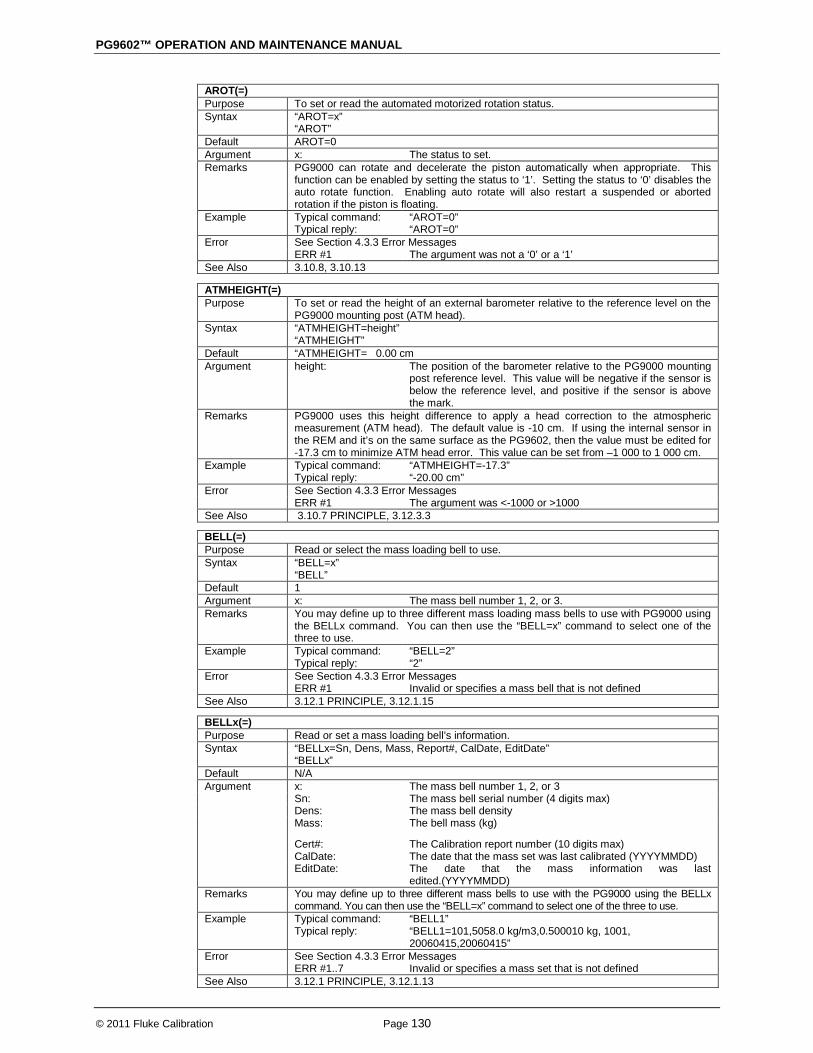
PG9602™ OPERATION AND MAINTENANCE MANUAL
© 2011 Fluke Calibration Page 130
AROT(=) Purpose To set or read the automated motorized rotation status. Syntax “AROT=x”
“AROT” Default AROT=0 Argument x: The status to set. Remarks PG9000 can rotate and decelerate the piston automatically when appropriate. This
function can be enabled by setting the status to ‘1’. Setting the status to ‘0’ disables the auto rotate function. Enabling auto rotate will also restart a suspended or aborted rotation if the piston is floating.
Example Typical command: Typical reply:
“AROT=0” “AROT=0”
Error See Section 4.3.3 Error Messages ERR #1 The argument was not a ‘0’ or a ‘1’ See Also 3.10.8, 3.10.13
ATMHEIGHT(=) Purpose To set or read the height of an external barometer relative to the reference level on the
PG9000 mounting post (ATM head). Syntax “ATMHEIGHT=height”
“ATMHEIGHT” Default “ATMHEIGHT= 0.00 cm Argument height: The position of the barometer relative to the PG9000 mounting
post reference level. This value will be negative if the sensor is below the reference level, and positive if the sensor is above the mark.
Remarks PG9000 uses this height difference to apply a head correction to the atmospheric measurement (ATM head). The default value is -10 cm. If using the internal sensor in the REM and it’s on the same surface as the PG9602, then the value must be edited for -17.3 cm to minimize ATM head error. This value can be set from –1 000 to 1 000 cm.
Example Typical command: Typical reply:
“ATMHEIGHT=-17.3” “-20.00 cm”
Error See Section 4.3.3 Error Messages ERR #1 The argument was <-1000 or >1000 See Also 3.10.7 PRINCIPLE, 3.12.3.3
BELL(=) Purpose Read or select the mass loading bell to use. Syntax “BELL=x”
“BELL” Default 1 Argument x: The mass bell number 1, 2, or 3. Remarks You may define up to three different mass loading mass bells to use with PG9000 using
the BELLx command. You can then use the “BELL=x” command to select one of the three to use.
Example Typical command: Typical reply:
“BELL=2” “2”
Error See Section 4.3.3 Error Messages ERR #1 Invalid or specifies a mass bell that is not defined See Also 3.12.1 PRINCIPLE, 3.12.1.15
BELLx(=) Purpose Read or set a mass loading bell’s information. Syntax “BELLx=Sn, Dens, Mass, Report#, CalDate, EditDate”
“BELLx” Default N/A Argument x: The mass bell number 1, 2, or 3 Sn: The mass bell serial number (4 digits max) Dens: The mass bell density Mass: The bell mass (kg)
Cert#: The Calibration report number (10 digits max) CalDate: The date that the mass set was last calibrated (YYYYMMDD) EditDate: The date that the mass information was last
edited.(YYYYMMDD) Remarks You may define up to three different mass bells to use with the PG9000 using the BELLx
command. You can then use the “BELL=x” command to select one of the three to use. Example Typical command:
Typical reply: “BELL1” “BELL1=101,5058.0 kg/m3,0.500010 kg, 1001, 20060415,20060415”
Error See Section 4.3.3 Error Messages ERR #1..7 Invalid or specifies a mass set that is not defined See Also 3.12.1 PRINCIPLE, 3.12.1.13
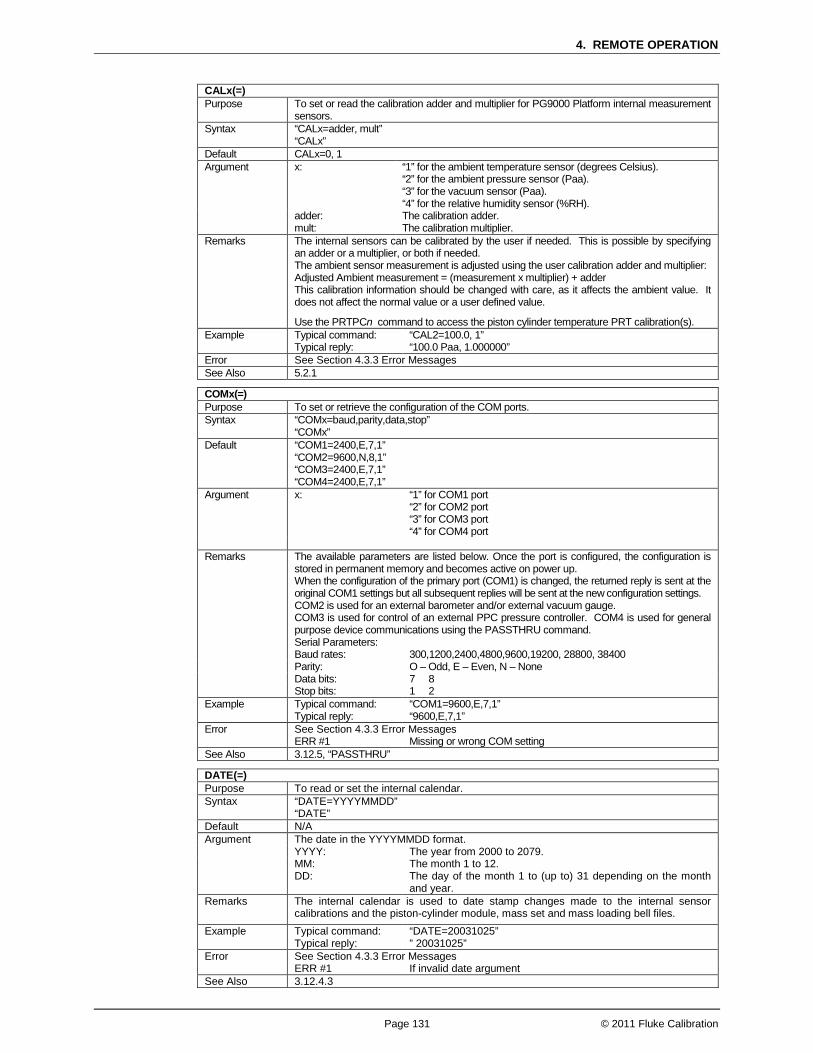
4. REMOTE OPERATION
Page 131 © 2011 Fluke Calibration
CALx(=) Purpose To set or read the calibration adder and multiplier for PG9000 Platform internal measurement
sensors. Syntax “CALx=adder, mult”
“CALx” Default CALx=0, 1 Argument x: “1” for the ambient temperature sensor (degrees Celsius).
“2” for the ambient pressure sensor (Paa). “3” for the vacuum sensor (Paa). “4” for the relative humidity sensor (%RH).
adder: The calibration adder. mult: The calibration multiplier. Remarks The internal sensors can be calibrated by the user if needed. This is possible by specifying
an adder or a multiplier, or both if needed. The ambient sensor measurement is adjusted using the user calibration adder and multiplier: Adjusted Ambient measurement = (measurement x multiplier) + adder This calibration information should be changed with care, as it affects the ambient value. It does not affect the normal value or a user defined value.
Use the PRTPCn command to access the piston cylinder temperature PRT calibration(s). Example Typical command:
Typical reply: “CAL2=100.0, 1” “100.0 Paa, 1.000000”
Error See Section 4.3.3 Error Messages See Also 5.2.1
COMx(=) Purpose To set or retrieve the configuration of the COM ports. Syntax “COMx=baud,parity,data,stop”
“COMx” Default “COM1=2400,E,7,1”
“COM2=9600,N,8,1” “COM3=2400,E,7,1” “COM4=2400,E,7,1”
Argument x: “1” for COM1 port “2” for COM2 port “3” for COM3 port “4” for COM4 port
Remarks The available parameters are listed below. Once the port is configured, the configuration is
stored in permanent memory and becomes active on power up. When the configuration of the primary port (COM1) is changed, the returned reply is sent at the original COM1 settings but all subsequent replies will be sent at the new configuration settings. COM2 is used for an external barometer and/or external vacuum gauge. COM3 is used for control of an external PPC pressure controller. COM4 is used for general purpose device communications using the PASSTHRU command. Serial Parameters:
Baud rates: 300,1200,2400,4800,9600,19200, 28800, 38400 Parity: O – Odd, E – Even, N – None Data bits: 7 8 Stop bits: 1 2 Example Typical command:
Typical reply: “COM1=9600,E,7,1” “9600,E,7,1”
Error See Section 4.3.3 Error Messages ERR #1 Missing or wrong COM setting See Also 3.12.5, “PASSTHRU”
DATE(=) Purpose To read or set the internal calendar. Syntax “DATE=YYYYMMDD”
“DATE” Default N/A Argument The date in the YYYYMMDD format. YYYY: The year from 2000 to 2079. MM: The month 1 to 12. DD: The day of the month 1 to (up to) 31 depending on the month
and year. Remarks The internal calendar is used to date stamp changes made to the internal sensor
calibrations and the piston-cylinder module, mass set and mass loading bell files. Example Typical command:
Typical reply: “DATE=20031025” ” 20031025”
Error See Section 4.3.3 Error Messages ERR #1 If invalid date argument See Also 3.12.4.3

PG9602™ OPERATION AND MAINTENANCE MANUAL
© 2011 Fluke Calibration Page 132
DIFLOAD Purpose Executes the mass load determined by the DIFSETUP command. Syntax “DIFLOAD” Remarks This command must be preceded by the DIFSETUP command. The DIFSETUP
command sets up the PG9000 and determines the proper mass load for offset determination. The DIFLOAD command executes the mass load determined by the DIFSETUP command and places the PG9000 into the offset determination mode. When in this mode, use the DIFOFFSET command to query the PG for the calculated differential offset. The DIFOFFSET command is also used to save the offset as the new differential mode RPM offset value, and to exit the offset determination mode. The ABORT command can also be used to exit the offset determination mode. The reply is the same nominal mass values returned by the DIFSETUP command that is expected to be loaded.
Example Typical command: Typical reply:
“DIFLOAD” “9.7 kg, 28.05 g”
Error See the “DIFSETUP” and “DIFOFFSET” commands. ERR #1
ERR #23 ERR #35
Argument is invalid. Vacuum reference not supported by this PG9000. The “DIFSETUP” was not used prior to this command.
See Also 3.10.4.1, “DIFLOAD”, “DIFSETUP”
DIFOFFSET(=) Purpose Set or read the differential offset value. Syntax “DIFOFFSET=offset, pressure”
“DIFOFFSET” Default Offset:
Pressure: 0 Pa 101325.0 Paa
Argument Offset:
“NEW” Saves the current calculation of RPM offset if PG9000 is currently in the offset determination mode, else set the differential offset value in Pa.
Pressure: The PG9000 defined pressure when the previously determined differential offset was saved or if Offset is “NEW”. This argument is ignored and should not be used.
Remarks The DIFOFFSET commands have two types of operation. If PG9000 is in the offset determination mode, the calculated offset of the external measurement device from the PG9000 defined pressure is returned along with the current PG9000 pressure. If the “NEW” arguments is given with this command, the calculated offset and PG9000 pressure are saved as the new RPM offset and pressure, and PG9000 exits the offset determination mode returning to normal operation with differential measurement mode enabled. If the PG9000 is not in the offset determination mode, this command reads back only the RPM offset and pressure as determined previously. The command can also be used to set them to another value.
Example Typical command: Typical reply:
“DIFOFFSET=7.1,97.100” “7.10 Pa, 97.10 000 Paa”
If PG7601 is in the offset determination mode: Typical command:
Typical reply: “DIFOFFSET=NEW” “4.13 Pa, 96.14321 Paa”
Error See the “DIFSETUP” and “DIFLOAD” commands. ERR #1
ERR #2 ERR #35
The Offset field is invalid or missing. The Pressure field is invalid or missing. Offset was “NEW” but the PG is not in the offset determination mode.
See Also 3.10.4.1, “DIFLOAD”, “DIFSETUP”

4. REMOTE OPERATION
Page 133 © 2011 Fluke Calibration
DIFSETUP Purpose Prepare PG9000 to determine the differential RPM mode offset. Syntax “DIFSETUP” Remarks The differential mode of operation requires that an RPM offset be determined. This
command sets up PG9000 to determine the RPM offset. The PG measurement mode is changed to absolute by vacuum, the mass load resolution is set to 0.01g, and the head correction is disabled. PG9000 must be setup to use an external pressure measurement device (RPM) connected to COM2 to execute this command. The reply to this command is the external device measurement; the true and the nominal mass load needed to generate the pressure indicated by the external device. After using this command to setup PG9000 for offset determination, use the “DIFLOAD” command to execute the mass load determined by this command. The external device (RPM) measurement, the actual true mass value, the main mass nominal value, and trim mass values that need to be loaded are returned by this command. It is provided in the following comma delimited format: bb.bbbbb Paa, aa.aaaaaa kg, mm.m kg, t.ttt g Where:
bb.bbbbb Paa: The barometer measurement in units of Pascal absolute. aa.aaaaaa kg: The actual total true mass value in units of kg. mm.m kg: The total of the main mass's nominal values in units of kg. t.tttg: The trim mass loaded in units of grams. Example Typical command:
Typical reply: “DIFSETUP” “97.23238 Paa, 9.728002 kg, 9.7 ,g, 28.05 g”
Error See the “DIFLOAD” and “DIFOFFSET” commands ERR #1 The barometer measurement resulted in an invalid mass load ERR #23
ERR #28 Vacuum reference not supported by this PG9000 An external measurement device has not been SETUP
See Also 3.10.4.1, “DIFLOAD”, “DIFOSSET(=)”
DUTHEIGHT(=) Purpose To set or read the height of an external Device Under Test (DUT) relative to the
reference level on the PG9000 mounting post (DUT head). Syntax “DUTHEIGHT=height”
“DUTHEIGHT” Default “ATMHEIGHT=0.00cm” Argument height: The position of the device under test relative to the PG9000
mounting post reference mark. This value will be negative if the DUT is below the reference level, and positive if the DUT is above the reference level.
Remarks PG9000 uses this height difference to apply a head correction to the pressure calculation. This value can be set from –1 000 to 1 000 cm.
Example Typical command: Typical reply:
“DUTHEIGHT=20” “20.00cm”
Error See Section 4.3.3 Error Messages ERR #1 The argument was <-1000 or >1000 See Also 3.10.7, 3.10.3
ERR Purpose To read the error messages of the last command. Syntax “ERR” Default ERR#=OK Argument N/A Remarks If the last response returned from PG9000 was an error (ERR#xx), then the error
message that corresponds to that error can be read. If an error is received and a valid command is sent to PG9000 before the “ERR” command has been sent, the error pointer is reset and an “ERR# 0 = OK” will be returned with the next “ERR” command. The *CLS command clears any pending error messages. See Error Message Summary List Section 4.3.3.
Example Typical command: Typical reply: Typical reply:
“ERR” “Unknown command” (previous invalid command) “OK” (no error)
Error None See Also 4.3.3, “AMHERR”

PG9602™ OPERATION AND MAINTENANCE MANUAL
© 2011 Fluke Calibration Page 134
LOCALG(=) Purpose Set or read the PG9000 local gravity. Syntax “LOCALG=x”
“LOCALG” Default “LOCALG=9.80665” Argument X: The current local gravity. Remarks The local gravity is used in the mass-to-pressure calculation. The Setup determines if
the local gravity, the normal gravity or a user defined gravity will be used for this calculation. The unit of measure is m/s2.
Example Typical command: Typical reply:
“LOCALG=9.805” “9.80500”
Error See Section 4.3.3 Error Messages ERR #1 If x is <8 or >11 See Also 2.4.3, 3.11, 3.12.6
LOCAL Purpose Place the device in the LOCAL mode. Syntax “LOCAL” Default N/A Argument N/A Remarks In LOCAL mode all front panel operations are available. The LOCAL command
deactivates REMOTE mode. Example Typical command:
Typical reply: “LOCAL” “LOCAL”
Error None See Also “REMOTE”
MASS(=) Purpose Read or set the current mass set. Syntax “MASS=n”
“MASS” Default N/A Argument N: The mass set number 1, 2, or 3. Remarks You may define up to three different mass sets to use with PG9000 using the MASSx
and MASSSETx commands. The MASS(=) command is then used to select the current active mass set. A mass set must be defined before selecting it. If an AMH mass set is specified, the AMH automated mass handler is initialized.
Example Typical command: Typical reply:
“MASS” “MASS=1”
Error See Section 4.3.3 Error Messages ERR #1
ERR #13 n invalid or specifies a mass set that is not defined AMH mass set was specified but an AMH automated mass handler was not detected.
See Also 3.12.1.10, 3.12.1 PRINCIPLE
MASSx(=) Purpose Read or set a mass set’s general information. Syntax “Massx=Sn,Dens,extra1,extra2,extra3,Cert#,CalDate,EditDate, AMH”
“Massx” Default N/A Argument x: The mass set number 1, 2, or 3. Sn: The mass set serial number (4 digits max). Dens: The main mass density. extra1/2/3: These are placeholders for data fields that are obsolete and are
always ‘0’. Cert#: The calibration report number (10 digits max). CalDate: The date that the mass set was last calibrated (YYYYMMDD). EditDate:
AMH:
The date that the mass information was last edited (YYYYMMDD). ‘0’ for a manual mass set ‘1’ for an AMH mass set.
Remarks You may define up to three different mass sets to use with PG9000 using the MASSx and MASSSETx command. The MASSSETx command must be used first. The MASSx command is then used to edit the mass set general information. If the “AMH” flag is set, the mass set defined must correspond exactly to the AMH’s mass set.
Example Typical command: Typical reply:
“MASS1” “MASS1=101,8000.0 kg/m3,0,0,0,1002, 20060415, 20060415, 0”
Error See Section 4.3.3 Error Messages ERR #1..9 Invalid arguments See Also 3.6, 3.12.1.6, 3.12.1 PRINCIPLE, “MASSSETx”
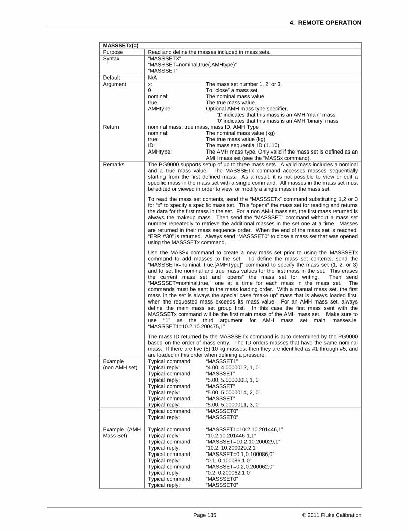
4. REMOTE OPERATION
Page 135 © 2011 Fluke Calibration
MASSSETx(=) Purpose Read and define the masses included in mass sets. Syntax “MASSSETX”
“MASSSET=nominal,true(,AMHtype)” “MASSSET”
Default N/A Argument x: The mass set number 1, 2, or 3. 0 To “close” a mass set. nominal: The nominal mass value. true:
AMHtype: The true mass value. Optional AMH mass type specifier. ‘1’ indicates that this mass is an AMH ‘main’ mass ‘0’ indicates that this mass is an AMH ‘binary’ mass
Return nominal mass, true mass, mass ID, AMH Type nominal:
true: ID: AMHtype:
The nominal mass value (kg) The true mass value (kg) The mass sequential ID (1..10) The AMH mass type. Only valid if the mass set is defined as an AMH mass set (see the “MASSx command).
Remarks The PG9000 supports setup of up to three mass sets. A valid mass includes a nominal and a true mass value. The MASSSETx command accesses masses sequentially starting from the first defined mass. As a result, it is not possible to view or edit a specific mass in the mass set with a single command. All masses in the mass set must be edited or viewed in order to view or modify a single mass in the mass set. To read the mass set contents, send the “MASSSETx” command substituting 1,2 or 3 for “x” to specify a specific mass set. This “opens” the mass set for reading and returns the data for the first mass in the set. For a non AMH mass set, the first mass returned is always the makeup mass. Then send the “MASSSET” command without a mass set number repeatedly to retrieve the additional masses in the set one at a time. Masses are returned in their mass sequence order. When the end of the mass set is reached, “ERR #30” is returned. Always send “MASSSET0” to close a mass set that was opened using the MASSSETx command. Use the MASSx command to create a new mass set prior to using the MASSSETx command to add masses to the set. To define the mass set contents, send the “MASSSETx=nominal, true,[AMHType]” command to specify the mass set (1, 2, or 3) and to set the nominal and true mass values for the first mass in the set. This erases the current mass set and “opens” the mass set for writing. Then send “MASSSET=nominal,true,” one at a time for each mass in the mass set. The commands must be sent in the mass loading order. With a manual mass set, the first mass in the set is always the special case “make up” mass that is always loaded first, when the requested mass exceeds its mass value. For an AMH mass set, always define the main mass set group first. In this case the first mass sent with the MASSSETx command will be the first main mass of the AMH mass set. Make sure to use “1” as the third argument for AMH mass set main masses.ie. “MASSSET1=10.2,10.200475,1” The mass ID returned by the MASSSETx command is auto determined by the PG9000 based on the order of mass entry. The ID orders masses that have the same nominal mass. If there are five (5) 10 kg masses, then they are identified as #1 through #5, and are loaded in this order when defining a pressure.
Example (non AMH set)
Typical command: Typical reply:
“MASSSET1” “4.00, 4.0000012, 1, 0”
Typical command: Typical reply:
“MASSSET” “5.00, 5.0000008, 1, 0”
Typical command: Typical reply:
“MASSSET” “5.00, 5.0000014, 2, 0”
Typical command: Typical reply:
“MASSSET” “5.00, 5.0000011, 3, 0”
Typical command: Typical reply:
“MASSSET0” “MASSSET0”
Example (AMH Mass Set)
Typical command: Typical reply:
“MASSSET1=10.2,10.201446,1” “10.2,10.201446,1,1”
Typical command: Typical reply:
“MASSSET=10.2,10.200029,1” “10.2, 10.200029,2,1”
Typical command: Typical reply:
”MASSSET=0.1,0.100086,0” “0.1, 0.100086,1,0”
Typical command: Typical reply:
”MASSSET=0.2,0.200062,0” “0.2, 0.200062,1,0”
Typical command: Typical reply:
“MASSSET0” “MASSSET0”
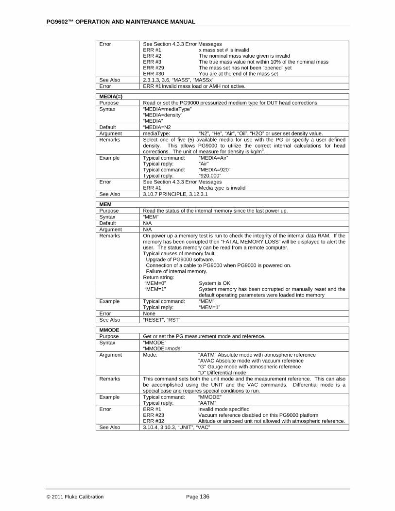
PG9602™ OPERATION AND MAINTENANCE MANUAL
© 2011 Fluke Calibration Page 136
Error See Section 4.3.3 Error Messages ERR #1
ERR #2 ERR #3 ERR #29 ERR #30
x mass set # is invalid The nominal mass value given is invalid The true mass value not within 10% of the nominal mass The mass set has not been “opened” yet You are at the end of the mass set
See Also 2.3.1.3, 3.6, “MASS”, “MASSx” Error ERR #1 Invalid mass load or AMH not active.
MEDIA(=) Purpose Read or set the PG9000 pressurized medium type for DUT head corrections. Syntax “MEDIA=mediaType”
“MEDIA=density” “MEDIA”
Default “MEDIA=N2 Argument mediaType: “N2”, “He”, “Air”, “Oil”, “H2O” or user set density value. Remarks Select one of five (5) available media for use with the PG or specify a user defined
density. This allows PG9000 to utilize the correct internal calculations for head corrections. The unit of measure for density is kg/m3.
Example Typical command: Typical reply: Typical command: Typical reply:
“MEDIA=Air” “Air” “MEDIA=920” “920.000”
Error See Section 4.3.3 Error Messages ERR #1 Media type is invalid See Also 3.10.7 PRINCIPLE, 3.12.3.1
MEM Purpose Read the status of the internal memory since the last power up. Syntax “MEM” Default N/A Argument N/A Remarks On power up a memory test is run to check the integrity of the internal data RAM. If the
memory has been corrupted then “FATAL MEMORY LOSS” will be displayed to alert the user. The status memory can be read from a remote computer. Typical causes of memory fault: Upgrade of PG9000 software. Connection of a cable to PG9000 when PG9000 is powered on. Failure of internal memory.
Return string: “MEM=0” System is OK “MEM=1” System memory has been corrupted or manually reset and the
default operating parameters were loaded into memory Example Typical command:
Typical reply: “MEM” “MEM=1”
Error None See Also “RESET”, “RST”
MMODE Purpose Get or set the PG measurement mode and reference. Syntax “MMODE”
“MMODE=mode” Argument Mode: "AATM" Absolute mode with atmospheric reference
"AVAC Absolute mode with vacuum reference "G" Gauge mode with atmospheric reference "D" Differential mode
Remarks This command sets both the unit mode and the measurement reference. This can also be accomplished using the UNIT and the VAC commands. Differential mode is a special case and requires special conditions to run.
Example Typical command: Typical reply:
“MMODE” “AATM”
Error ERR #1 ERR #23 ERR #32
Invalid mode specified Vacuum reference disabled on this PG9000 platform Altitude or airspeed unit not allowed with atmospheric reference.
See Also 3.10.4, 3.10.3, “UNIT”, “VAC”

4. REMOTE OPERATION
Page 137 © 2011 Fluke Calibration
MRES(=) Purpose Read or set the PG9000 mass loading resolution. Syntax “MRES=massResolution”
“MRES” Default “MRES=0.01g Argument MassResolution: The mass loading resolution in grams. Remarks You must set the resolution that PG9000 uses to convert user provided pressure
requests into mass loads. PG9000 will calculate the required mass load to the precision defined by the mass loading resolution. The maximum resolution is 0.001 gram, and the minimum is 100 g. The mass resolution is automatically set to 100 g whenever an AMH mass set is made active or AMH is initialized.
Example Typical command: Typical reply:
“MRES=.01” “MRES=0.010g”
Error See Section 4.3.3 Error Messages ERR #1 The resolution given is greater that 100g of less than 0.001 g See Also 3.10.10
MROT(=) Purpose Read or set the manual motorized piston rotation status. Syntax “MROT=rotationStatus”
“MROT” Default “MROT=0” Argument Rotation Status: “ 1” Accelerates the piston rotation.
“-1” Decelerates (brakes) the piston rotation. “ 0” Aborts current acceleration or deceleration
Remarks The rotation of the PG9000 piston (with bell installed) may be controlled manually instead of using the auto rotate function (see the “AROT” command). The PG9000 will only rotate the piston if the bell is installed and the piston position is not near or against the top stop or bottom stop of the piston travel. This command is not typically used when the auto-rotate feature is enabled.
Example Typical command: Typical reply:
“MROT=1” “MROT=1”
Error See Section 4.3.3 Error Messages ERR #1 The argument given is not “-1”, “0” or a “1” See Also 3.10.13, 3.10.8, “AROT”
MR Purpose Read the current mass load variables. Syntax “MR” Default N/A Argument N/A Remarks The actual true mass value, main mass nominal value, and trim mass values of the
active mass load are retrieved with this command. The data is provided in the following comma delimited format: aa.aaaaaaa kg, mm.m kg, t.ttt g Where:
aa.aaaaaaa kg: The actual total true mass value. mm.m kg: The total of the main masses nominal values (mass > 0.1 kg). t.tttg: The trim mass loaded. These values are the result of a user provided pressure request or mass request. Since
the actual total true mass value is a result of the true mass values, its resolution is not controlled by the “MRES” command.
Example Typical command: Typical reply:
“MR” “20.687002 kg, 20.6 Kg, 77.000 g”
Error None See Also 3.6

PG9602™ OPERATION AND MAINTENANCE MANUAL
© 2011 Fluke Calibration Page 138
MS(=) Purpose To set the nominal main (mass ≥ 0.1 kg) and trim mass to be loaded on PG9000. The
actual mass value used is determined by the true mass values of the selected mass set. Syntax “MS=mm.m kg, t.ttt g” Default N/A Argument mm.m kg: The total of the main masses nominal values to be loaded. t.ttt g: The trim mass to be loaded. Remarks The user may specify a target for PG9000 in mass or pressure. When a mass target is
given, the selected mass set is used to determine the masses available for loading. PG9000 starts at the largest value (with the lowest sequence numbered) main mass until enough mass has been found to satisfy the main mass request. The trim mass is then added to the total of the required true mass values. Then a series of actions may occur: 1. If auto rotate feature is enabled, the masses are decelerated to a stop. 2. If the auto generation piston raise feature is enabled, the piston is be lifted. 3. If an AMH mass handler is active, the appropriate mass is loaded. 4. If the auto generation is enabled, the external PPC attempts to float the piston. 5. If the automatic rotation is enabled, the masses are rotated when floating. 6. The PG9000 achieves a Ready condition at the requested mass load.
This command replies before execution of the steps actually starts. The “PR” command can be used to monitor the status of these events and determine when the PG9000 measurement is Ready. The “ABORT” command or changing to local front panel operation using the [ESC] key, the LOCAL command or a GPIB go to local function stops the operation.
Example Typical command: Typical reply:
“MS=5, 50” “5.0 kg, 50.000 g”
Error See Section 4.3.3 Error Messages ERR #1
ERR #2 If the first argument is invalid If the second argument is invalid
See Also 3.10.12, 3.6, 3.10.11, 3.10.11.1, “PR” , “PS=” , “ABORT” , “AROT” , “PGEN”
OHMS Purpose Read the mounting post PRT resistances. Syntax “OHMS” Default N/A Argument N/A Remarks The mounting post temperature is measured and used for internal calculations. This
command always returns the last measured value using the internal PRTs. If the current Setup does not specify “INTERNAL” as the measurement source, this measurement is not made, and the value returned is a measurement made when the unit was powered up. The PG9000 uses two PRTs to independently measure the mounting post temperature (“PRT1” and “PRT2”).
Example Typical command: Typical reply:
“OHMS” “109.519 ohms, 110.995 ohms” (PG9000)
Error None See Also 5.2.1.5

4. REMOTE OPERATION
Page 139 © 2011 Fluke Calibration
PASSTHRUx Purpose To allow the host PC to communicate with a device connected to the PG9000 COM
ports. Syntax “PASSTHRUx = cmd”
“PASSTHRUx” Arguments x:
cmd: 2, 3 or 4 to access the COM2, COM3 or COM4 ports. The command string to send to the external device
Remarks The COM2, COM3 and COM4 ports are used by the PG9000 to communicate with external devices. The PASSTHRU command allows direct communications with a device connected to one of these ports as long as the device is not actively being used by the PG (such as an active barometer or vacuum sensor on COM2 or a PPC pressure controller on COM3). The device must be set to the same port settings as the PG and accept a carriage return followed by a line feed as a terminator. When the PASSTHRU command is used to send a command to a device, any replies from the device will be passed back as a reply. This pass back function continues until any other command is sent to the PG9000. If the device does not reply, then no reply will be generated from the PASSTHRUx= command. The Query format (no argument) will allow the external device to pass replies back thru the PG9000 without issuing a command first. This continues until any other command is sent to the PG9000. If communicating with a PPC via the COM3 port for the purpose of polling the PPC output pressure, the preferred command is PPCPR.
Example Cmd sent: Query reply:
“PASSTHRU3=VER” “FLUKE PPC4 VER1.01a” (device is a PPC4 on COM3)
Error See Section 4.3.3 Error Messages ERR #1
ERR#27 Invalid port ‘x’ The device on the port is currently active
See Also “COMx”, “PPCPR”
PCTx(=) Purpose Set or read the source for the piston-cylinder temperature measurement. Also optionally
sets the USER defined measurement. Syntax “PCTx=source, meas”
“PCTx=source” “PCTx”
Default 20 °C if the source is DEFAULT Argument x: The setup number from 1 to 13. See the SETUP command.
Setup is reserved for remote command use only. Source: The measurement source. This can be INTERNAL, NORMAL,
or USER. Meas: The current measurement used. This can only be set if the
source argument is USER. If specified, the limit for this argument is 0 to 40 °C
Remarks PG9000 has two internal piston-cylinder mounting post PRT sensors, using the average of the two values for piston-cylinder temperature in calculations. Optionally another source may be used for this measurement. The measurement source can be the internal sensors, a user defined fixed value, or the normal value. The Setup number allows 13 separate configurations for each sensor. The SETUP command selects which of the 13 to use. Setup number 1 is restricted as INTERNAL only to serve as manufacturer’s fixed Setup, and cannot be changed. The meas argument is used to allow the user to define a fixed value if the source is set to USER. The reply will always include the source and the meas fields.
Example Typical command: Typical reply:
“PCT2=USER,25” “USER,25dC”
Typical command: Typical reply:
“PRT9=INTERNAL” “INTERNAL, 21.34 dC”
Error See Section 4.3.3 Error Messages ERR #1
ERR #2 ERR #3
The setup number x is invalid The source argument is invalid The meas argument is invalid
See Also 3.11, 1.2.1.3, “SETUP”

PG9602™ OPERATION AND MAINTENANCE MANUAL
© 2011 Fluke Calibration Page 140
PGEN(=) Purpose Set or read the piston float target for automatic piston floating (using an external
pressure generation/control component). Also can turn the automated pressure generation function OFF and ON.
Syntax “PGEN=m.m” “PGEN”
Default PGEN=0.0 (off) Argument N/A Remarks An external pressure generation/control component can be used to automatically float
the PG9000 piston. This command specifies the piston position to which the automated pressure generation function sets the piston when floating or refloating it. The auto generation stops pressure control once the piston passes the piston float target and then does not control again until the piston falls outside of the piston position "Ready" limits (see PISTONRDY cmd). Setting PGEN to 0 turns OFF automated pressure generation in the same manner as turning it OFF locally from the PG Terminal. The pressure generation/control component should be “configured” (see pressure generation/control component Operation and Maintenance Manual) and the “PGEN” command should be issued whenever the Device Under Test is changed or the piston is changed.
Example Typical command: Typical reply:
“PGEN=1.5” “PGEN=1.5mm”
Error See Section 4.3.3 Error Messages ERR #1 The argument is invalid See Also 3.10.9, “PPC”, “READYx”
PISTONRDYx(=) Purpose Read or set a piston-cylinder module’s rotation rate limits. Syntax “PISTONRDYx=MinRPM, MaxRPM
“PISTONRDYx” Default N/A Argument MinRPM: The minimum allowed rotation speed at which the measurement
becomes Ready [rpm]. If autorotate is enabled, this is also the point at which the rotation system will engage. This does not apply if the bell is not loaded.
MaxRPM: The target maximum rotation rate when automated rotation engages to rotate the piston. This does not apply if the bell is not loaded.
Remarks There are a number of conditions to allow the PG9000 measurement to become Ready. These two piston-cylinder module dependent limits determine when the rotation rate is in the correct limits. Below 3 kg mass load the MinRPM limit is over ridden to a lower value to help optimize performance at lower mass loads.
Example Typical command: Typical reply:
“PISTONRDY1” “10, 50”
Error See Section 4.3.3 Error Messages ERR #1..2 x invalid first or second argument See Also 3.4, 3.4.2, 3.12.1.1, “READYx”
PISTONVARx(=) Purpose Read or set a piston-cylinder module’s characteristics. Syntax “PISTONVARx=Sn,PCalpha,CylAlpha,DefCoef,Tension,Offset, k (P)”
“PISTONVARx” Default N/A Argument x: The piston-cylinder number 1, 2, or 3 Sn: The piston-cylinder serial number (4 digits max) Pcalpha: The piston temperature coefficient CylAlpha: The cylinder temperature coefficient DefCoef: The piston-cylinder Ae pressure coefficient Tension: The surface tension Offset: The reference level offset from the mounting post reference
mark Remarks You may define up to seventeen different piston-cylinder sets to use with PG9000 using
the PISTONx command. Once defined, the piston cylinder variables are edited using the PISTONVARx command. This would commonly be used for updating the variables after a calibration.
Example Typical command: Typical reply:
“PISTONVAR1” 225, 5.5000 E-6/dC, 4.5000 E-6/dC, 5.3800 E-6/MPa, 0.0000000, 32.4600mm , 0.000 E-6
Error See Section 4.3.3 Error Messages ERR #1..7 x invalid first through seventh argument See Also 3.12.1.1, PISTONx(=)
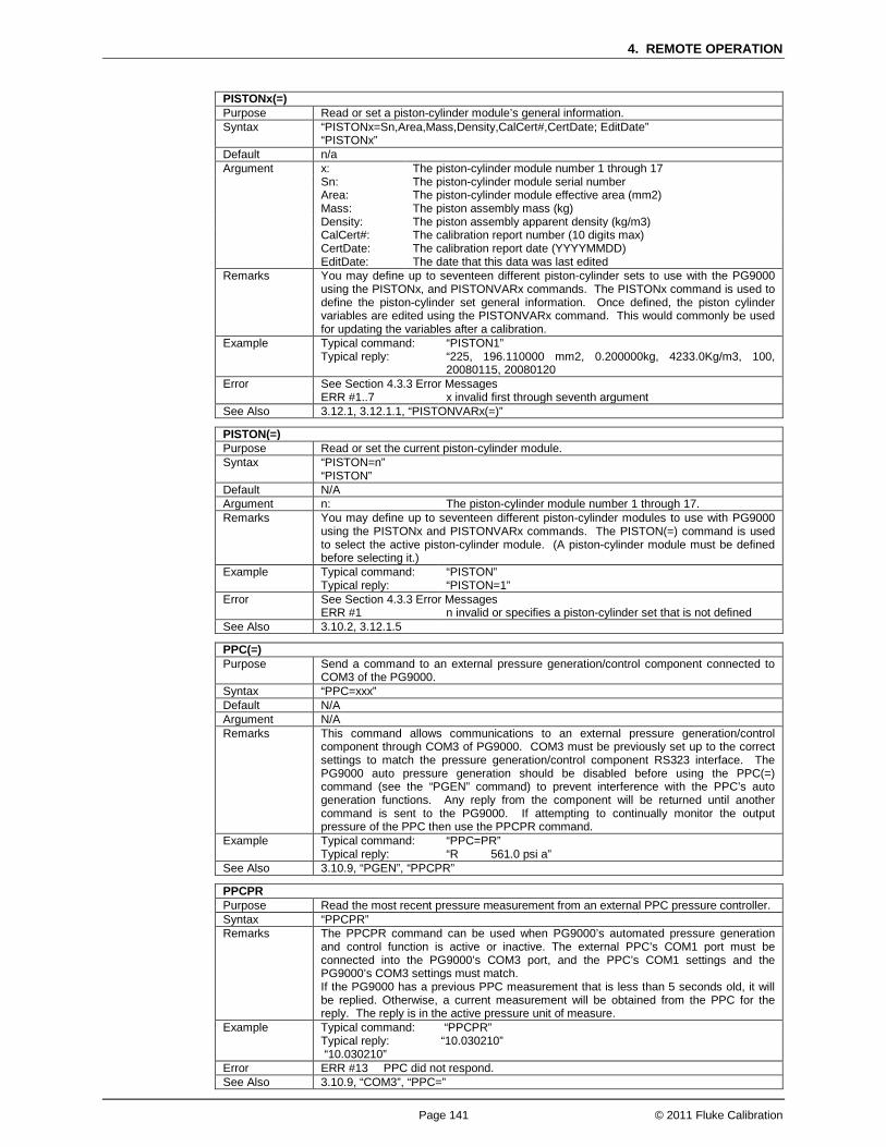
4. REMOTE OPERATION
Page 141 © 2011 Fluke Calibration
PISTONx(=) Purpose Read or set a piston-cylinder module’s general information. Syntax “PISTONx=Sn,Area,Mass,Density,CalCert#,CertDate; EditDate”
“PISTONx” Default n/a Argument x: The piston-cylinder module number 1 through 17 Sn: The piston-cylinder module serial number Area: The piston-cylinder module effective area (mm2) Mass: The piston assembly mass (kg) Density: The piston assembly apparent density (kg/m3) CalCert#: The calibration report number (10 digits max) CertDate: The calibration report date (YYYYMMDD) EditDate: The date that this data was last edited Remarks You may define up to seventeen different piston-cylinder sets to use with the PG9000
using the PISTONx, and PISTONVARx commands. The PISTONx command is used to define the piston-cylinder set general information. Once defined, the piston cylinder variables are edited using the PISTONVARx command. This would commonly be used for updating the variables after a calibration.
Example Typical command: Typical reply:
“PISTON1” “225, 196.110000 mm2, 0.200000kg, 4233.0Kg/m3, 100, 20080115, 20080120
Error See Section 4.3.3 Error Messages ERR #1..7 x invalid first through seventh argument See Also 3.12.1, 3.12.1.1, “PISTONVARx(=)”
PISTON(=) Purpose Read or set the current piston-cylinder module. Syntax “PISTON=n”
“PISTON” Default N/A Argument n: The piston-cylinder module number 1 through 17. Remarks You may define up to seventeen different piston-cylinder modules to use with PG9000
using the PISTONx and PISTONVARx commands. The PISTON(=) command is used to select the active piston-cylinder module. (A piston-cylinder module must be defined before selecting it.)
Example Typical command: Typical reply:
“PISTON” “PISTON=1”
Error See Section 4.3.3 Error Messages ERR #1 n invalid or specifies a piston-cylinder set that is not defined See Also 3.10.2, 3.12.1.5
PPC(=) Purpose Send a command to an external pressure generation/control component connected to
COM3 of the PG9000. Syntax “PPC=xxx” Default N/A Argument N/A Remarks This command allows communications to an external pressure generation/control
component through COM3 of PG9000. COM3 must be previously set up to the correct settings to match the pressure generation/control component RS323 interface. The PG9000 auto pressure generation should be disabled before using the PPC(=) command (see the “PGEN” command) to prevent interference with the PPC’s auto generation functions. Any reply from the component will be returned until another command is sent to the PG9000. If attempting to continually monitor the output pressure of the PPC then use the PPCPR command.
Example Typical command: Typical reply:
“PPC=PR” “R 561.0 psi a”
See Also 3.10.9, “PGEN”, “PPCPR”
PPCPR Purpose Read the most recent pressure measurement from an external PPC pressure controller. Syntax “PPCPR” Remarks The PPCPR command can be used when PG9000’s automated pressure generation
and control function is active or inactive. The external PPC’s COM1 port must be connected into the PG9000’s COM3 port, and the PPC’s COM1 settings and the PG9000’s COM3 settings must match. If the PG9000 has a previous PPC measurement that is less than 5 seconds old, it will be replied. Otherwise, a current measurement will be obtained from the PPC for the reply. The reply is in the active pressure unit of measure.
Example Typical command: “PPCPR” Typical reply: “10.030210” “10.030210”
Error ERR #13 PPC did not respond. See Also 3.10.9, “COM3”, “PPC=”
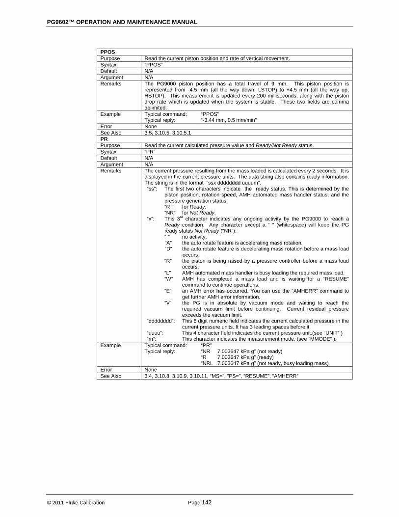
PG9602™ OPERATION AND MAINTENANCE MANUAL
© 2011 Fluke Calibration Page 142
PPOS Purpose Read the current piston position and rate of vertical movement. Syntax “PPOS” Default N/A Argument N/A Remarks The PG9000 piston position has a total travel of 9 mm. This piston position is
represented from -4.5 mm (all the way down, LSTOP) to +4.5 mm (all the way up, HSTOP). This measurement is updated every 200 milliseconds, along with the piston drop rate which is updated when the system is stable. These two fields are comma delimited.
Example Typical command: Typical reply:
“PPOS” “-3.44 mm, 0.5 mm/min”
Error None See Also 3.5, 3.10.5, 3.10.5.1 PR Purpose Read the current calculated pressure value and Ready/Not Ready status. Syntax “PR” Default N/A Argument N/A Remarks The current pressure resulting from the mass loaded is calculated every 2 seconds. It is
displayed in the current pressure units. The data string also contains ready information. The string is in the format “ssx dddddddd uuuum”. “ss”: The first two characters indicate the ready status. This is determined by the
piston position, rotation speed, AMH automated mass handler status, and the pressure generation status:
“R ” for Ready, “NR” for Not Ready. “x”: This 3rd character indicates any ongoing activity by the PG9000 to reach a
Ready condition. Any character except a “ ” (whitespace) will keep the PG ready status Not Ready (“NR”): “ ” no activity. “A” the auto rotate feature is accelerating mass rotation. “D” the auto rotate feature is decelerating mass rotation before a mass load
occurs. “R” the piston is being raised by a pressure controller before a mass load
occurs. “L” AMH automated mass handler is busy loading the required mass load. “W” AMH has completed a mass load and is waiting for a “RESUME”
command to continue operations. “E” an AMH error has occurred. You can use the “AMHERR” command to
get further AMH error information. “V” the PG is in absolute by vacuum mode and waiting to reach the
required vacuum limit before continuing. Current residual pressure exceeds the vacuum limit.
“dddddddd”: This 8 digit numeric field indicates the current calculated pressure in the current pressure units. It has 3 leading spaces before it.
“uuuu”: This 4 character field indicates the current pressure unit.(see “UNIT” ) “m”: This character indicates the measurement mode. (see “MMODE” ).
Example Typical command: Typical reply:
“PR” “NR 7.003647 kPa g” (not ready) “R 7.003647 kPa g” (ready) “NRL 7.003647 kPa g” (not ready, busy loading mass)
Error None See Also 3.4, 3.10.8, 3.10.9, 3.10.11, “MS=”, “PS=”, “RESUME”, “AMHERR”

4. REMOTE OPERATION
Page 143 © 2011 Fluke Calibration
PRTPCn Purpose Set or read the mounting post PRT temperature sensor calibration data. Syntax “PRTPCn=Sn, slope, zero, report number, cal date”
“PRTPC=Sn, slope, zero, report number, cal date” “PRTPCn” “PRTPC”
Suffix n: ‘1’ to access PRT1, ‘2’ to access PRT2. Optional (defaults to ‘1’) Default 1, 0.3896, 100.00, 1, 19880101 Argument Sn: The serial number from 0 to 9999 slope: The PRT slope (Ohms/0 °C) zero: The PRT resistance at 0 °C cert number: The calibration report number cal date The calibration date (yyyymmdd) Remarks The mounting post PRT data can be read or set using this command. Care must be
taken to ensure that this data is not overwritten.
PG9600 has two piston-cylinder mounting post PRTs. Example Typical command:
Typical reply: “PRTPC1” “103, 0.3896 ohms/dC, 99.999500 ohms, 1001, 20080115
Error See Section 4.3.3 Error Messages ERR #1..5
ERR #7 If the arguments are missing or invalid The date is invalid
See Also 5.2.1, 5.2.1.5
PS= Purpose To set a new PG9000 target pressure. Syntax “PS=targ” Default N/A Argument N/A Remarks The pressure command is interpreted in the current pressure unit of measure. If a
pressure is requested that is outside the range of operation, the pressure request is not implemented and an error message is returned. The mass load needed to set the pressure is calculated using the current mass loading resolution and the measured pressure resulting from this mass is calculated. . Then a series of actions can occur:
1. If the auto rotate feature is enabled, the masses are decelerated to a stop.
2. If the auto generation piston raise feature is enabled, the piston is lifted.
3. If an AMH automated mass handler is active, the appropriate mass is loaded.
4. If an AMH is active and the mass resolution is set to less than 100g, the PG9000 waits for the “RESUME” command to be sent before proceeding. This gives the host program the opportunity to instruct the operator to load trim mass before pressure generation and piston rotation proceed.
5. If auto generation is enabled, the external PPC attempts to float the piston.
6. If the automatic rotation is enabled, the masses are rotated when floating. This command replies before these actions actually start. Once a pressure generation command is executed the “PR” command can subsequently be used to monitor the Ready status. To stop the operation, use any of the following: the “ABORT” command or changing to local front panel operation using the [ESC] key, the LOCAL command, or a GPIB go-to-local function will stop the operation.
Example Typical command: Typical reply:
“PS=100” “100.0000 kPa g”
Error See Section 4.3.3 Error Messages ERR #1 If target results in an invalid mass load See Also 3.10.11, 3.10.12, 3.10.10, 3.10.3, “MS=”, “PR”, “UNIT=”, “RESUME”

PG9602™ OPERATION AND MAINTENANCE MANUAL
© 2011 Fluke Calibration Page 144
READYx(=) Purpose Set or read the ready criteria for a specific “Setup” Syntax “READYx=USER, RdyBand, RdyVac”
“READYx=”DEFAULT” (specifies to use fixed defaults) “READYx”
Default “READYx=USER, 2.5mm, 5Paa” Argument x:
RdyBand:
The setup number whose ready criteria are to be accessed (1 to 13) Piston position “ready band” (±mm)
VacLim: The vacuum ready limit (Paa) Remarks The PG9000 uses the piston position and the vacuum measurement (in absolute by vac
mode) to determine if the Ready/Not Ready condition. Other factors can also keep the PG9000 measurement from being Ready (such as an active external pressure controller, active rotation system, active AMH automated mass handler). The piston position must be within the ready band (“RdyBand”) to allow a ready condition. In absolute by vacuum measurement mode, the vacuum measurement must also be below the Vacuum Limit (“VacLim”). Each “Setup” defined for the PG9000 can have a different set of Ready/Not Ready criteria. If DEFAULT settings are specified, then the values are fixed and cannot be changed. The piston position ready limits define the piston position beyond which the GEN function refloats the piston when GEN is ON. Piston rotation rate limits are in the individual piston-cylinder file.
Example Typical command: Typical reply:
“READY2=USER, 3, 10” “USER, 3.0mm, 10Paa”
Error See Section 4.3.3 Error Messages ERR #1,2,3,4 Invalid arguments See Also 3.4, 3.12.1.1, “SETUP”, “VACP”, “PISTONRDYx(=)”, “READYCK(=)”
READYCK(=) Purpose To set or check the ready check flag, or, used to determine if a Not Ready condition has
occurred. Syntax “READYCK=1”
“READYCK” Default READYCK=0 Argument N/A Remarks The internal ready check flag is cleared whenever PG9000 reaches a Not Ready (NR)
condition. The “READYCK” command will return the status of this flag. This flag can be set only by sending the “READYCK=1” command while PG9000 is in a Ready condition. If you send the “READYCK=1” command when PG9000 is in a Not Ready (NR) condition, the reply will be “READYCK=0”. If you set READYCK=1 when PG9000 achieves a Ready (R) condition, you can use READYCK later to determine if a Not Ready (NR) condition has occurred. If NR has occurred READYCK returns “0”. If NR has not occurred READYCK returns “1”.
Example Typical command: Typical reply: Typical reply:
“READYCK=1” “READYCK=1” (If PG9000 condition is Ready) “READYCK=0” (if PG9000 condition is Not Ready)
Error See Section 4.3.3 Error Messages ERR #1 If n is not a 1 See Also 3.4
REMOTE Purpose To place PG9000 into a remote lock-out mode. Syntax “REMOTE” Default N/A Argument N/A Remarks A REMOTE command deactivates the front panel. All front panel controls will be disabled.
The REMOTE command can only be canceled by a LOCAL command or by turning off PG9000 power then reapplying it.
Example Typical command: Typical reply:
“REMOTE” “REMOTE”
Error None See Also LOCAL

4. REMOTE OPERATION
Page 145 © 2011 Fluke Calibration
RESET Purpose To reset all operating parameters to factory default settings. Syntax “RESET” Default N/A Argument N/A Remarks The reset command can be given to return the PG9000 to a known state.
This command is the same as locally executing a “Reset Sets”. Example Typical command:
Typical reply: “RESET” “RESET”
Error None See Also 3.12.9.1
RESUME(=mode) Purpose Sets the resume mode. Syntax “RESUME=mode” Default “RESUME=1” Argument Mode: ‘0’ “RESUME” command is not needed to complete a remote pressure
set operation . ‘1’ “RESUME” command is needed to complete any remote pressure
set operation Remarks “RESUME=1” is needed only if it is necessary for PG9000 operation to pause after a
pressure target has been given to allow the operator to load mass. This is the case when using a manual mass set or when using AMH automated mass handling and manually loading trim masses.
Example Typical command: Typical reply:
“RESUME=1” “RESUME=1”
Error None See Also 3.10.11, 3.4, “PS=”, “RESUME”
RESUME Purpose Resume the suspended process of setting a pressure. Syntax “RESUME” Default N/A Argument N/A Remarks When “RESUME=1” using RESUME(=mode), after setting a new target pressure using
the “PS=” command, the process of setting the pressure is suspended after the PG9000 calculates the new target mass load (and loads the if an AMH automatic mass handler is active). The pause is too allow a host program to instruct the operator to load trim mass if desired. The RESUME command ends the pause, allowing the auto-rotate and auto-generate functions to execute is enabled. The activity status field of the “PR” field can be used to determine when the PG9000 has suspended operation and is waiting for the “RESUME” command.
Example Typical command: Typical reply:
“RESUME” “RESUME”
Error None See Also 3.10.11, 3.4, “PS=”, “PR=”, “RESUME(=mode)”
SETUP(=) Purpose To change or read the current SETUP to be used. Syntax “SETUP=n”
“SETUP” Default “SETUP=1” Argument N/A Remarks Up to 13 SETUP files can be created by the user to allow quick change from one
configuration of pressure calculation sources to another. Each configuration can specify the source of the ambient measurements, the gravity, and the Ready/Not Ready criteria. The “AMBHx”, “AMBPx”, “AMBTx”, “READYx”, “VACP” and “PCTX” commands reference the SETUP command. The first setup (“SETUP=1”) is reserved for the factory default setup, and cannot be changed. Selecting a setup that references an external device (barometer or vacuum gauge) can take up to 5 seconds to reply.
Example Typical command: Typical reply:
“SETUP=2” “2”
Error See Section 4.3.3 Error Messages ERR #1
ERR #13 If setup is invalid Setup requires use of external device which is not responding.
See Also 3.11, “AMBHx”, “AMBPx”, “AMBTx”, “READYx”, “VACP”, “PCT”

PG9602™ OPERATION AND MAINTENANCE MANUAL
© 2011 Fluke Calibration Page 146
SN Purpose To read the PG9000 serial number. Syntax “SN” Default N/A Argument N/A Remarks Each PG9000 is assigned a serial number. This command reads this number back. Example Typical command:
Typical reply: “SN” “201”
Error None
SPEED Purpose To read the current piston rotation speed and rotation decay (deceleration). Syntax “SPEED” Default N/A Argument N/A Remarks The current piston rotation speed and decay rate are returned separated by a comma.
The decay rate is returned as ‘0’ if there is not enough valid data to calculate the rate. The speed will also be returned as ‘0’ if the bell is not installed.
Example Typical command: Typical reply:
“SPEED” “44.2 rpm, 2.3 rpm/min
Error None See Also 3.10.5
TIME(=) Purpose To read or set the internal real time clock. Syntax “TIME=HH:MMxp”
“TIME” Default N/A Argument The time is in the HH:MMxp format. HH:
MM: xp:
The hour 1 to 12 The minute 00 to 59 “am” or “pm”
Remarks The internal time clock is part of the internal calendar. The seconds are always set to “00” when setting the time.
Example Typical command: Typical reply:
“TIME=8:10PM” “8:10pm”
Error See Section 4.3.3 Error Messages ERR #1 If invalid time argument See Also 3.12.4.3
UCOEF Purpose To read the conversion coefficient used to convert Pascal to the current pressure unit of
measure. Syntax “UCOEF” Default N/A Argument N/A Remarks Use this command to read the pressure conversion coefficient used to convert pressure
in Pascal to the displayed pressure units. Pressure in Pascal multiplied by this coefficient yields the pressure in the PG9000 units.
Example Typical command: Typical reply:
“UCOEF” (current units are “kPa”) “1.000000e-003”
Error None See Also 7.1.1, 3.10.3, “UNIT”
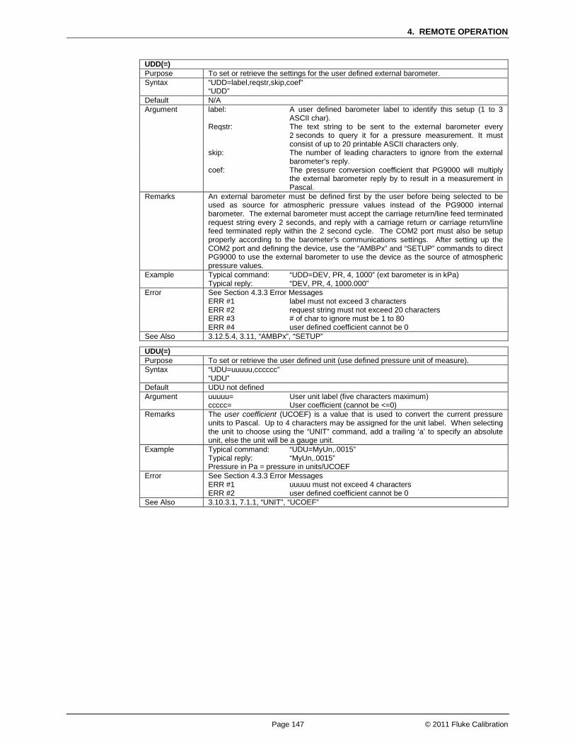
4. REMOTE OPERATION
Page 147 © 2011 Fluke Calibration
UDD(=) Purpose To set or retrieve the settings for the user defined external barometer. Syntax “UDD=label,reqstr,skip,coef”
“UDD” Default N/A Argument label: A user defined barometer label to identify this setup (1 to 3
ASCII char). Reqstr: The text string to be sent to the external barometer every
2 seconds to query it for a pressure measurement. It must consist of up to 20 printable ASCII characters only.
skip: The number of leading characters to ignore from the external barometer’s reply.
coef: The pressure conversion coefficient that PG9000 will multiply the external barometer reply by to result in a measurement in Pascal.
Remarks An external barometer must be defined first by the user before being selected to be used as source for atmospheric pressure values instead of the PG9000 internal barometer. The external barometer must accept the carriage return/line feed terminated request string every 2 seconds, and reply with a carriage return or carriage return/line feed terminated reply within the 2 second cycle. The COM2 port must also be setup properly according to the barometer’s communications settings. After setting up the COM2 port and defining the device, use the “AMBPx” and “SETUP” commands to direct PG9000 to use the external barometer to use the device as the source of atmospheric pressure values.
Example Typical command: Typical reply:
“UDD=DEV, PR, 4, 1000” (ext barometer is in kPa) “DEV, PR, 4, 1000.000”
Error See Section 4.3.3 Error Messages ERR #1
ERR #2 ERR #3 ERR #4
label must not exceed 3 characters request string must not exceed 20 characters # of char to ignore must be 1 to 80 user defined coefficient cannot be 0
See Also 3.12.5.4, 3.11, “AMBPx”, “SETUP”
UDU(=) Purpose To set or retrieve the user defined unit (use defined pressure unit of measure). Syntax “UDU=uuuuu,cccccc”
“UDU” Default UDU not defined Argument uuuuu=
ccccc= User unit label (five characters maximum) User coefficient (cannot be <=0)
Remarks The user coefficient (UCOEF) is a value that is used to convert the current pressure units to Pascal. Up to 4 characters may be assigned for the unit label. When selecting the unit to choose using the “UNIT” command, add a trailing ‘a’ to specify an absolute unit, else the unit will be a gauge unit.
Example Typical command: Typical reply:
“UDU=MyUn,.0015” “MyUn,.0015”
Pressure in Pa = pressure in units/UCOEF Error See Section 4.3.3 Error Messages ERR #1
ERR #2 uuuuu must not exceed 4 characters user defined coefficient cannot be 0
See Also 3.10.3.1, 7.1.1, “UNIT”, “UCOEF”

PG9602™ OPERATION AND MAINTENANCE MANUAL
© 2011 Fluke Calibration Page 148
UDV(=) Purpose To set or retrieve the settings for the user defined external vacuum gauge. Syntax “UDV=label,reqstr,skip,coef”
“UDV” Default N/A Argument label: A user defined vacuum gauge label to identify this setup (1 to 3
ASCII char). Reqstr: The text string to be sent to the external vacuum gauge every
2 seconds to query it for a pressure measurement. It must consist of up to 20 printable ASCII characters only.
skip: The number of leading characters to ignore from the external vacuum gauge’s reply.
coef: The pressure conversion coefficient that PG9000 will multiply the external vacuum sensor’s reply by to result in a measurement in Pascal.
Remarks An external vacuum gauge must be defined before being selected as a source of vacuum pressure under the PG9000 bell jar. The external vacuum gauge must accept the carriage return/line feed terminated request string every 2 seconds, and reply with a carriage return or carriage return/line feed terminated reply within the 2 second cycle. The COM2 port must also be setup properly according to the vacuum gauge’s communications settings. After setting up the COM2 port and defining the device, use the “VACPx” and “SETUP” commands. It is possible to read both an external barometer and an external vacuum sensor with the PG COM2 port. The barometer must be an RPM3 or RPM4 plugged into the PG COM2 port, and selected as an active external barometer. The vacuum sensor is then plugged into the RPM3/RPM4’s COM2 port. The RPM3/RPM4’s COM2 port must be set to the same settings as the vacuum sensor.
Example Typical command: Typical reply:
“UDV=DEV, PR, 4, 100” (ext vacuum sensor is in mbar) “DEV, PR, 4, 100.0000”
Error See Section 4.3.3 Error Messages ERR #1
ERR #2 ERR #3 ERR #4
label must not exceed 3 characters request string must not exceed 20 characters # of char to ignore must be 1 to 80 user defined coefficient cannot be 0
See Also 3.12.5.5, 3.11, “VACPx”, “SETUP”, “COM2”
UL(=) Purpose Set or read the upper limit of an external pressure generation/control component. Syntax “UL=xxxx”
“UL” Default Default N/A. Argument xxxx= Controller’s upper limit in the controller’s pressure units Remarks An external pressure controller can have an upper limit set to prevent accidental
overpressure conditions. The controller must be properly initialized prior to using this command. The reply will be in the controller’s format. Please consult the controller’s Operation and Maintenance Manual, UL Section, for details about its upper limit and “UL” reply.
Example Typical command: Typical reply:
“UL=1000” “1000.00 kPa g”
Error See the controller’s manual for details about its “UL” command. ERR #13 External controller not detected See Also 3.10.9.3 “PGEN”
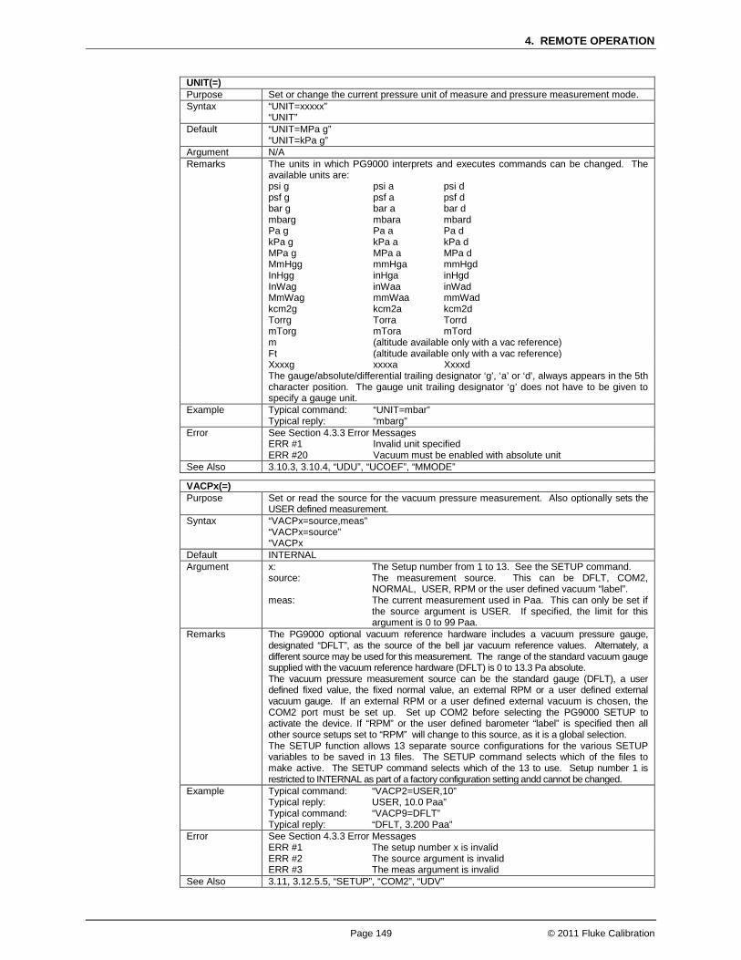
4. REMOTE OPERATION
Page 149 © 2011 Fluke Calibration
UNIT(=) Purpose Set or change the current pressure unit of measure and pressure measurement mode. Syntax “UNIT=xxxxx”
“UNIT” Default “UNIT=MPa g”
“UNIT=kPa g” Argument N/A Remarks The units in which PG9000 interprets and executes commands can be changed. The
available units are: psi g
psf g bar g mbarg Pa g kPa g MPa g MmHgg InHgg InWag MmWag kcm2g Torrg mTorg
psi a psf a bar a mbara Pa a kPa a MPa a mmHga inHga inWaa mmWaa kcm2a Torra mTora
psi d psf d bar d mbard Pa d kPa d MPa d mmHgd inHgd inWad mmWad kcm2d Torrd mTord
m (altitude available only with a vac reference) Ft (altitude available only with a vac reference) Xxxxg xxxxa Xxxxd The gauge/absolute/differential trailing designator ‘g’, ‘a’ or ‘d’, always appears in the 5th
character position. The gauge unit trailing designator ‘g’ does not have to be given to specify a gauge unit.
Example Typical command: Typical reply:
“UNIT=mbar” “mbarg”
Error See Section 4.3.3 Error Messages ERR #1
ERR #20 Invalid unit specified Vacuum must be enabled with absolute unit
See Also 3.10.3, 3.10.4, “UDU”, “UCOEF”, “MMODE”
VACPx(=) Purpose Set or read the source for the vacuum pressure measurement. Also optionally sets the
USER defined measurement. Syntax “VACPx=source,meas”
“VACPx=source” “VACPx
Default INTERNAL Argument x: The Setup number from 1 to 13. See the SETUP command. source: The measurement source. This can be DFLT, COM2,
NORMAL, USER, RPM or the user defined vacuum “label”. meas: The current measurement used in Paa. This can only be set if
the source argument is USER. If specified, the limit for this argument is 0 to 99 Paa.
Remarks The PG9000 optional vacuum reference hardware includes a vacuum pressure gauge, designated “DFLT”, as the source of the bell jar vacuum reference values. Alternately, a different source may be used for this measurement. The range of the standard vacuum gauge supplied with the vacuum reference hardware (DFLT) is 0 to 13.3 Pa absolute. The vacuum pressure measurement source can be the standard gauge (DFLT), a user defined fixed value, the fixed normal value, an external RPM or a user defined external vacuum gauge. If an external RPM or a user defined external vacuum is chosen, the COM2 port must be set up. Set up COM2 before selecting the PG9000 SETUP to activate the device. If “RPM” or the user defined barometer “label” is specified then all other source setups set to “RPM” will change to this source, as it is a global selection. The SETUP function allows 13 separate source configurations for the various SETUP variables to be saved in 13 files. The SETUP command selects which of the files to make active. The SETUP command selects which of the 13 to use. Setup number 1 is restricted to INTERNAL as part of a factory configuration setting andd cannot be changed.
Example Typical command: Typical reply:
“VACP2=USER,10” USER, 10.0 Paa”
Typical command: Typical reply:
“VACP9=DFLT” “DFLT, 3.200 Paa”
Error See Section 4.3.3 Error Messages ERR #1
ERR #2 ERR #3
The setup number x is invalid The source argument is invalid The meas argument is invalid
See Also 3.11, 3.12.5.5, “SETUP”, “COM2”, “UDV”
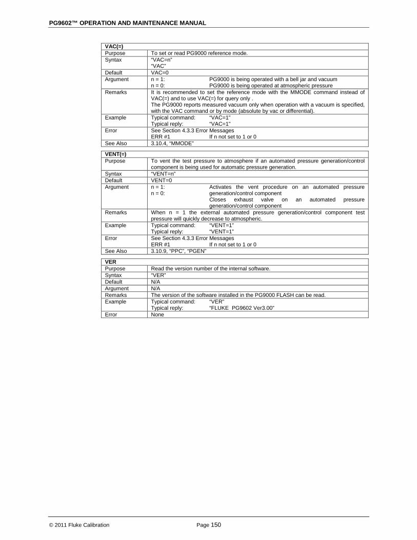
PG9602™ OPERATION AND MAINTENANCE MANUAL
© 2011 Fluke Calibration Page 150
VAC(=) Purpose To set or read PG9000 reference mode. Syntax “VAC=n”
“VAC” Default VAC=0 Argument n = 1:
n = 0: PG9000 is being operated with a bell jar and vacuum PG9000 is being operated at atmospheric pressure
Remarks It is recommended to set the reference mode with the MMODE command instead of VAC(=) and to use VAC(=) for query only . The PG9000 reports measured vacuum only when operation with a vacuum is specified, with the VAC command or by mode (absolute by vac or differential).
Example Typical command: Typical reply:
“VAC=1” “VAC=1”
Error See Section 4.3.3 Error Messages ERR #1 If n not set to 1 or 0 See Also 3.10.4, “MMODE”
VENT(=) Purpose To vent the test pressure to atmosphere if an automated pressure generation/control
component is being used for automatic pressure generation. Syntax “VENT=n” Default VENT=0 Argument n = 1:
n = 0: Activates the vent procedure on an automated pressure generation/control component Closes exhaust valve on an automated pressure generation/control component
Remarks When n = 1 the external automated pressure generation/control component test pressure will quickly decrease to atmospheric.
Example Typical command: Typical reply:
“VENT=1” “VENT=1”
Error See Section 4.3.3 Error Messages ERR #1 If n not set to 1 or 0 See Also 3.10.9, “PPC”, “PGEN”
VER Purpose Read the version number of the internal software. Syntax “VER” Default N/A Argument N/A Remarks The version of the software installed in the PG9000 FLASH can be read. Example Typical command:
Typical reply: “VER” “FLUKE PG9602 Ver3.00”
Error None

4. REMOTE OPERATION
Page 151 © 2011 Fluke Calibration
4.4 Status System The status system includes the status reporting system which reports general PG9000 events. The user can select which PG9000 events will cause a status change event. These events are then reported to the status system (bit7 and bit3 of the status byte register), which also must be configured for the STATus subsystem to generate the service requests described in Section 4.4.1, Status Reporting System.
There are two 16 bit event registers that make up the top layer of the status subsystem. The OPERation status register handles conditions that are normal for PG9000. The QUEStionable status register handles events that could cause measurements to be made under questionable conditions.
4.4.1 Status Reporting System The PG9000 status reporting system is used to track and report system status and errors. The status subsystem is layered under and reports to the status reporting system. It follows the model of the IEEE Std 488.2 and works for the COM1 and the IEEE-488 port with slight differences. PG9000 can be programmed to respond to various status conditions by asserting the SRQ of the IEEE-488 interface. The COM1 port cannot be supported in this manner, so polling must be used.
4.4.1.1 Status Byte Register PG9000 contains an 8 bit status byte register that reflects the general status of PG9000.
Table 23. Status Byte Register
OPER (128)
RQS/MSS (64)
ESB (32)
MAV (16)
N/A (8)
ERROR (4)
N/A (2)
RSR (1)
This register is affected by the PG9000 reply output queue, the error queue, the Standard Event Status register, the Ready Event Status register, and the STATus subsystem.
(“∗STB?” or “∗SRE n”)
OPERation Bit7 (128)
OPERation summary bit
RQS/MSS Bit6 (64)
Standard Event Status Register (“∗ESR?” or “∗ESE n”)
ESB Bit5 (32)
PON Bit7
URQ Bit6
CMD Bit5
EXE Bit4
DDE Bit3
QYE Bit2
RQC Bit1
OPC Bit0
MAV Bit4 (16)
OUTPUT QUEUE
N/A Bit3 (8)
ERROR Bit2 (4)
ERROR QUEUE
N/A Bit1 (2)
N/A Bit0 (1)
Figure 21. Status Byte Register

PG9602™ OPERATION AND MAINTENANCE MANUAL
© 2011 Fluke Calibration Page 152
The status byte register can be read using the “*STB?” query, or by performing a serial poll on the IEEE-488 bus. If you read this using a serial poll then bit 6 is the RQS. If the “∗STB?” query is used, then bit 6 is the MSS bit. All of the other bits are common to both types of query. Each of these status bits can cause an SRQ to occur. The Service Request Enable Register (“∗SRE” program message) determines which of these flags are able to assert the SRQ line. This enabled register has a matching set of bits that each will enable the designated bit to cause an SRQ, except for the RQS/MSS bit(s) which cannot cause an SRQ. If you set this register to 20 ($14 hex), an SRQ will occur if the MAV or the ERROR bit are set. The description of these bits are given as:
• OPER: OPERational event register summary bit (Bit 7) This bit is not supported by PG9000.
• RQS: Requested Service (Bit 6) Indicates that the SRQ line of the IEEE-488 interface has been asserted by PG9000. This bit is cleared when a serial poll is performed on PG9000, and is a part of the status byte register when read using a serial poll. This bit does not apply if the COM1 port is being used.
• MSS: Master Summary Status (Bit 6) Indicates that an event or events occurred that caused PG9000 to request service from the Host, much like the RQS bit. Unlike the RQS bit, it is READ ONLY and can be only cleared when the event(s) that caused the service request are cleared.
• ESB: Event Summary Bit (Bit 5) Indicates if an enabled bit in the Standard Event Status Register became set. (See the section below.)
• MAV: Message Available Bit (Bit 4) Indicates that at least one reply message is waiting in the PG9000 IEEE-488 output queue.
• ERR: Error Queue not empty (Bit 2) Indicates that at least one command error message is waiting in the PG9000 IEEE-488 error message queue. Use the “SYSTem:ERRor?” query to get this message.

4. REMOTE OPERATION
Page 153 © 2011 Fluke Calibration
4.4.1.2 Standard Event Register PG9000 contains an 8 bit Standard Event Register that reflects specific PG9000 events. Enabled events in this register will set or clear the ESB bit of the status byte register.
Table 24. Standard Event Register
PON (128)
URQ (64)
CMD (32)
EXE (16)
DDE (8)
QYE (4)
RQC (2)
OPC (1)
This register can be read using the “*ESR?” query. Each of these status bits can set the ESB bit of the status byte register, causing a SRQ to occur IF the ESB bit is enabled to do so. The Standard Event Status Enable Register (“∗ESE” program message) determines which of these flags are able to assert the ESB bit. The description of these bits are given as:
• PON: Power On (Bit 7) Indicates that the PG9000 power has been cycled since the last time this bit was read or cleared.
• URQ: User Request (Bit 6) Indicates that PG9000 was set to local operation manually from the front panel by the user (pressing the ESC key).
• CMD: Command Error (Bit 5) Indicates that a remote command error has occurred. A command error is typically a syntax error in the use of a correct program message.
• EXE: Execution Error (Bit 4) Indicates if a remote program message cannot be processed due to device related condition.
• DDE: Device Dependent Error (Bit 3) Indicates that an internal error has occurred in PG9000 such as a transducer time-out.
• QYE: Query Error (Bit 2) Indicates that an error has occurred in the protocol for program message communications. This is typically caused by a program message being sent to PG9000 without reading a waiting reply.
• RQC: Request Control (Bit 1) This bit is not supported as PG9000 cannot become the active controller in charge.
• OPC: Operation Complete (Bit 0) Indicates that PG9000 has completed all requested functions.

PG9602™ OPERATION AND MAINTENANCE MANUAL
© 2011 Fluke Calibration Page 154
Notes
Page 155 © 1998-2010 Fluke Calibration
5. Maintenance, Adjustments And Calibration
5.1 Introduction PG9000 was designed for very low maintenance operation. Standard preventative maintenance includes:
• Adjustment of piston position measurement system (see Section 5.2.2) • Cleaning piston-cylinders (see Sections 5.3.3). • Lubricating piston-cylinder modules (see Section 5.3.4) • Cleaning masses (see Section 5.4.1) • Adjustment/calibration of on-board ambient conditions sensors (see Sections 5.2.1.2 - 5.2.1.4 ) • Calibration of piston-cylinder temperature platinum resistance thermometer(s) (PRT) (see Section
5.2.1.5) • Calibration of reference vacuum sensor (see Section 5.2.1.6) • Calibration of piston-cylinder modules and mass set (see Sections 5.3.5, 5.4.2) • Drive belt replacement (see Section 5.2.3)
This section provides information on maintenance, adjustment and calibration procedures and certain repair procedures.
Note Calibration, maintenance and repair services for PG9000 are offered by authorized Fluke Calibration Authorized Service Providers (see Table 28).
Caution • PG9000 is a sophisticated measuring instrument with advanced on-board
features and functions. Before assuming that unexpected behavior is caused by a system defect or breakdown, use this manual and other training facilities to become thoroughly familiar with PG9000 operation. For rapid assistance in specific situations, see Section 6, Troubleshooting.
• PG9000 is covered by a limited 1 year warranty (see Section 7.4). Unauthorized service or repair during the warranty period is undertaken at the owner's risk and may cause damage that is NOT covered under product warranty and/or may void the product warranty.
Warning • Use only specified replacement fuses (see Section 1.2.1).
• PG9000 should only be repaired by an approved technician.
PG9602™ OPERATION AND MAINTENANCE MANUAL
© 2011 Fluke Calibration Page 156
5.2 Platform The PG9000 Platform consists of the PG9000 Base, PG Terminal and the PG9000 Remote Electronics Module (REM). Local user interface is through the keypad and display on the PG Terminal. Remote communications and on board (built in) sensors are connected to the REM or located inside.
5.2.1 Calibration / Adjustment Of On-board Measurement Functions
5.2.1.1 Principles The PG9000 Platform includes sensors to measure ambient and instrument conditions. These sensors may need calibration or adjustment. The calibration and/or adjustments are performed using functions accessed by pressing [SPECIAL] and selecting <7cal>. The on-board measurement functions that can be adjusted or calibrated include:
• Barometric pressure sensor – internal to REM • Relative humidity sensor – TH Probe external to REM (Hart 2626-S) • Ambient temperature sensor – TH Probe external to REM (Hart 2626-S) • Piston-cylinder module temperature sensors – Internal to mounting post • Piston position measurement system – Internal to Base • Reference vacuum gauge (optional) – External to bell jar
The measurement uncertainty specification of the on-board sensor should be taken into consideration when selecting a reference relative to which to adjust them (see Section 1.2.1.3). The ambient pressure, temperature and relative humidity sensors do not require a high level reference. They are typically verified and adjusted relative to a reference without being removed from the platform. The PG9000 CAL function supports a user defined adder and multiplier that are used to offset and, if necessary, adjust the slope of the sensors output. The adder and multiplier adjust the sensor output as follows:
Corrected Output = (Measured Output X Multiplier) + Adder Where:
• Corrected output, measured output and adder are in the current unit of measure of the sensor
• Multiplier is dimensionless [SPECIAL], <7cal> provides capabilities to view internal sensor outputs and edit the Adders and Multipliers. The CAL view function provides an additional digit of resolution relative to other displays of internal sensor outputs. To calibrate or adjust the on-board sensors, compare their outputs to a reference and adjust the corresponding Adder and/or Multiplier as needed to arrive at acceptable agreement.
5.2.1.2 Barometric Pressure Sensor PURPOSE To view and adjust the output of the on-board barometric sensor.
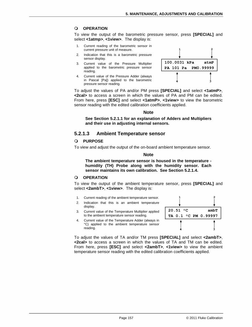
5. MAINTENANCE, ADJUSTMENTS AND CALIBRATION
Page 157 © 2011 Fluke Calibration
OPERATION To view the output of the barometric pressure sensor, press [SPECIAL] and select <1atmp>, <1view>. The display is:
1. Current reading of the barometric sensor in current pressure unit of measure.
2. Indication that this is a barometric pressure sensor display.
3. Current value of the Pressure Multiplier applied to the barometric pressure sensor reading.
4. Current value of the Pressure Adder (always in Pascal [Pa]) applied to the barometric pressure sensor reading.
100.0031 kPa atmP PA 101 Pa PM0.99999
To adjust the values of PA and/or PM press [SPECIAL] and select <1atmP>, <2cal> to access a screen in which the values of PA and PM can be edited. From here, press [ESC] and select <1atmP>, <1view> to view the barometric sensor reading with the edited calibration coefficients applied.
Note See Section 5.2.1.1 for an explanation of Adders and Multipliers and their use in adjusting internal sensors.
5.2.1.3 Ambient Temperature sensor PURPOSE To view and adjust the output of the on-board ambient temperature sensor.
Note The ambient temperature sensor is housed in the temperature - humidity (TH) Probe along with the humidity sensor. Each sensor maintains its own calibration. See Section 5.2.1.4.
OPERATION To view the output of the ambient temperature sensor, press [SPECIAL] and select <2ambT>, <1view>. The display is:
1. Current reading of the ambient temperature sensor. 2. Indication that this is an ambient temperature
display. 3. Current value of the Temperature Multiplier applied
to the ambient temperature sensor reading. 4. Current value of the Temperature Adder (always in
°C) applied to the ambient temperature sensor reading.
20.51 °C ambT TA 0.1 °C PM 0.99997
To adjust the values of TA and/or TM press [SPECIAL] and select <2ambT>, <2cal> to access a screen in which the values of TA and TM can be edited. From here, press [ESC] and select <2ambT>, <1view> to view the ambient temperature sensor reading with the edited calibration coefficients applied.

PG9602™ OPERATION AND MAINTENANCE MANUAL
© 2011 Fluke Calibration Page 158
5.2.1.4 Relative Humidity Sensor PURPOSE To view and adjust the output of the on-board relative humidity sensor.
Note The relative humidity sensor is housed in the temperature - humidity (TH) Probe along with the ambient temperature sensor. Each sensor maintains its own calibration. See Section 5.2.1.3.
OPERATION To view the output of the relative humidity sensor, press [SPECIAL] and select <3%RH>, <1view>. The display is:
1. Current reading of the relative humidity sensor.
2. Indication that this is a relative humidity display.
3. Current value of the Humidity Multiplier applied to the relative humidity sensor reading.
43.2 %RH amb%RH HA 5 %RH HM 0.99984
4. Current value of the Humidity Adder (always in %RH) applied to the relative humidity sensor reading.
To adjust the values of HA and/or HM press [SPECIAL] and select <3%RH>, <2cal> to access a screen in which the values of HA and HM can be edited. From here, press [ESC] and select <3%RH>, <1view> to view the relative humidity sensor reading with the edited calibration coefficients applied.
Note See Section 5.2.1.1 for an explanation of Adders and Multipliers and their use in adjusting internal sensors.
5.2.1.5 Piston-Cylinder Module Temperature Sensors PURPOSE To view and adjust the output of the on-board temperature sensors that are used to measure the temperature of the piston-cylinder module.
PRINCIPLE The piston-cylinder module temperature is measured by two platinum resistance thermometers (PRTs) embedded into the PG9000 mounting post. The two PRT values are averaged to determine the piston-cylinder module temperature. The resistances of the PRTs are read by PG9000's internal ohmic measurement system and temperature is calculated as follows:
Temperature = (Measured resistance - resistance at 0 °C) / slope
The PRTs are 10052 4-pole type following DIN Norm 43760. The current supplied to the PRTs is 1 mA and the slope of resistance relative to temperature over the valid temperature range of 0 to 40 °C is 0.3896 Ω/°C. The uncertainty specification is ± 0.1 °C (± 0.04 Ω) with a resolution of 0.01 °C. The ohmic measurement system in PG9000 is self-calibrated using on-board 100 and 107 Ω reference resistors. The normal calibration procedure of the PRTs is to remove them from the PG9000 mounting post and determine the offsets (actual resistances at 0 °C) by calibration. To remove the PRTs from the PG9000 mounting post, follow the instructions provided at the end of this section, Mounting Post PRT Removal.
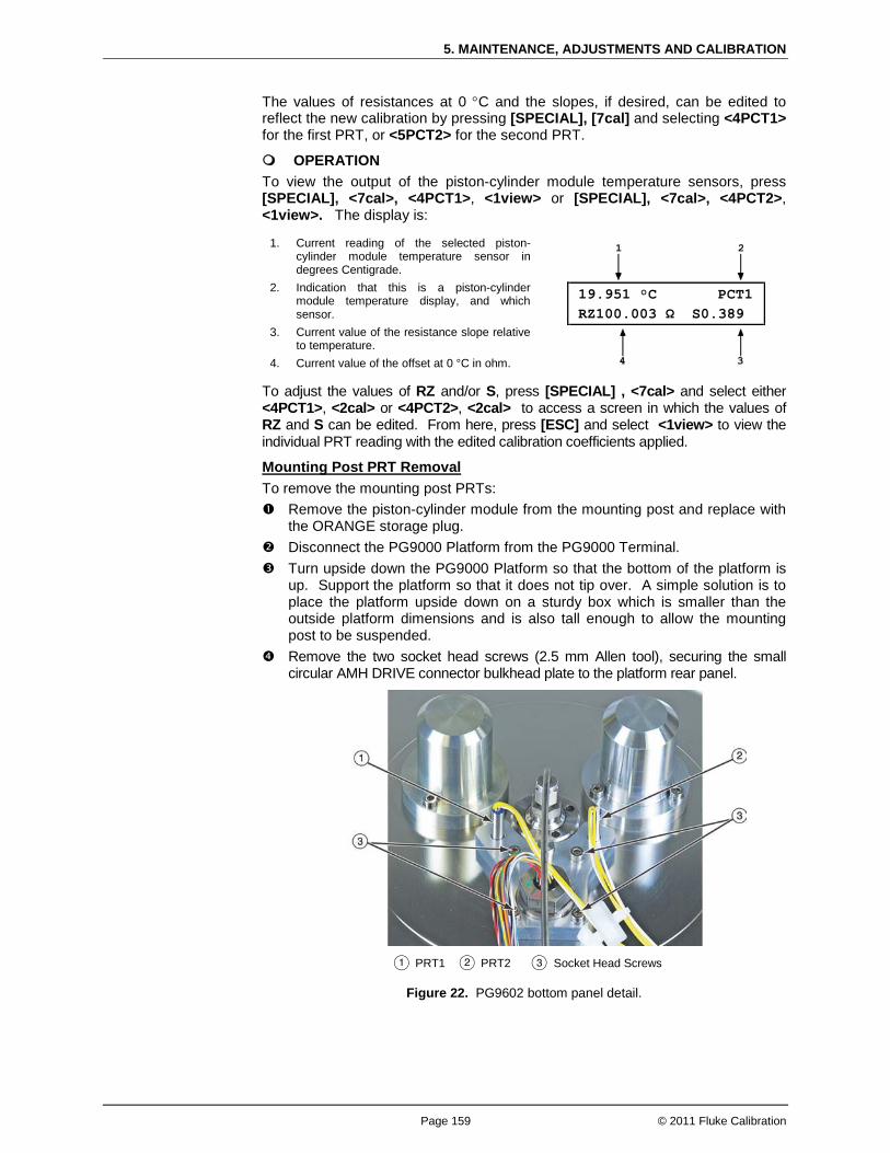
5. MAINTENANCE, ADJUSTMENTS AND CALIBRATION
Page 159 © 2011 Fluke Calibration
The values of resistances at 0 °C and the slopes, if desired, can be edited to reflect the new calibration by pressing [SPECIAL], [7cal] and selecting <4PCT1> for the first PRT, or <5PCT2> for the second PRT.
OPERATION To view the output of the piston-cylinder module temperature sensors, press [SPECIAL], <7cal>, <4PCT1>, <1view> or [SPECIAL], <7cal>, <4PCT2>, <1view>. The display is:
1. Current reading of the selected piston-cylinder module temperature sensor in degrees Centigrade.
2. Indication that this is a piston-cylinder module temperature display, and which sensor.
3. Current value of the resistance slope relative to temperature.
4. Current value of the offset at 0 °C in ohm.
19.951 °C PCT1 RZ100.003 Ω S0.389
To adjust the values of RZ and/or S, press [SPECIAL] , <7cal> and select either <4PCT1>, <2cal> or <4PCT2>, <2cal> to access a screen in which the values of RZ and S can be edited. From here, press [ESC] and select <1view> to view the individual PRT reading with the edited calibration coefficients applied.
To remove the mounting post PRTs: Mounting Post PRT Removal
Remove the piston-cylinder module from the mounting post and replace with the ORANGE storage plug.
Disconnect the PG9000 Platform from the PG9000 Terminal. Turn upside down the PG9000 Platform so that the bottom of the platform is
up. Support the platform so that it does not tip over. A simple solution is to place the platform upside down on a sturdy box which is smaller than the outside platform dimensions and is also tall enough to allow the mounting post to be suspended.
Remove the two socket head screws (2.5 mm Allen tool), securing the small circular AMH DRIVE connector bulkhead plate to the platform rear panel.
PRT1 PRT2 Socket Head Screws
Figure 22. PG9602 bottom panel detail.

PG9602™ OPERATION AND MAINTENANCE MANUAL
© 2011 Fluke Calibration Page 160
Loosen - but do not remove - the four socket head screws (3 mm) located on the PRT/cable pass through plate. The plate is located on the underside of the platform. Make sure to note the location of PRT1 and PRT2: PRT1 has longer leads than PRT2. PRT1 installs in the mounting post hole that is furthest from the circular connector location on the rear panel. Maintaining orientation of PRT1 and PRT2 assures consistency of piston-cylinder temperature measurement. The PRTs are able to be removed by gently grasping the shafts (not the wires) and sliding out in a straight motion.
Slide the PRTs out of the mounting post.
Note Once the PRTs are removed from the Base it is recommended that they be reconnected to the REM for temperature readout. The REM includes 100 and 107 ohm reference resistors . Reading resistance on the PRTs in combination with the REM includes any errors contributed by the reference resistors and the ohmic measurement circuit.
After reinstalling the PRTs in their correct position (see step 5) and tightening the four socket head screws, reassemble in the reverse order. Thermal grease may be applied lightly to the PRTs, if available.
Reconnect the PG9000 terminal to the PG9000 Platform using the cable supplied.
Power up PG9000 and verify proper operation of all on-board sensors.
5.2.1.6 Reference Vacuum Sensor (optional) PURPOSE To view and adjust the output of the reference vacuum sensor.
OPERATION To view the output of the reference vacuum sensor, press [SPECIAL] and select <7cal>, <6vac>, <1view>. The display is:
1. Current reading of the vacuum sensor in Pascal. Reads “> 13” whenever the current reading is greater than 13 Pa.
2. Indication that this is a vacuum display. 3. Current value of the Vacuum Multiplier
applied to the vacuum sensor reading. 4. Current value of the Vacuum Adder (always
in Pa) applied to the vacuum sensor reading.
6.52 Pa vac VA 0.5 VM 0.99984
To adjust the values of VA and/or VM press [SPECIAL] and select <6vac>, <2cal> to access a screen in which the values of VA and VM can be edited. From here, press [ESC] and select <6vac>, <1view> to view the vacuum sensor reading with the edited calibration coefficients applied.
Note See Section 5.2.1.1 for an explanation of Adders and Multipliers and their use in adjusting internal sensors.

5. MAINTENANCE, ADJUSTMENTS AND CALIBRATION
Page 161 © 2011 Fluke Calibration
5.2.2 Piston Position Detection Adjustment PURPOSE To adjust the piston position measurement system.
PRINCIPLE The PG9000 piston position measurement operates on the LVDT (Linear Variable Differential Transformer) principle. There is a pair of LVDT sensors embedded in the mounting post, near the bottom, on opposite sides. The bottom of the mass loading bell has an iron speed ring that couples with the field produced by the LVDTs. As the bell moves, the LVDT signal changes proportionally to bell position, and therefore piston position. The signal is translated into relative position in the ± 4.5 mm stroke of the piston (see Section 3.5). This provides a non-contact method of determining piston position relative to a lower and upper travel stop. The piston position and fall rate can be viewed from the [SYSTEM] run screen (see Section 3.10.5.1). The piston position indication system must be periodically realigned by a semi-automated on-board routine. This routine defines and records the LVDT output at the piston HI and LO stop positions.
OPERATION The operation of adjusting the piston position is different based on using a manual mass set versus an AMH mass set. See the appropriate sections below based on which type of mass set is being used.
Note • Refer to piston stroke schematic Figure 14. • If the PG9000 Platform is equipped with an AMH mass set, see Special
Considerations When Using an AMH Mass Set.
To adjust the PG9000 piston position indication system, load the mass bell on the piston and a 5 kg mass disc. Then press [SPECIAL], <7cal>, <5Pposition>, <2cal>.
Special Considerations When Using a Manual Mass Set
The prompt <Hold piston at max down stop> appears. Place the piston in the fully down position – be sure the system pressure is vented and that the piston low stop springs are fully compressed. Press [ENT]. The lower travel position is now defined. The prompt <Hold piston at max up stop> appears. Increase pressure to the PG9000 TEST connection to raise the piston to the full top stop position. The objective is to fully compress the springs so that the piston is truly at the high stop position. Apply pressure underneath the piston that is the equivalent to at least 5 kg greater than the pressure required to float the piston with the current load. For example, if a 10 kPa/kg piston-cylinder is being used, apply enough pressure that is at least equivalent to 5 kg + 5 kg = 100 kPag. Press [ENT]. The upper travel position is now defined. Press [SPECIAL] and select <7cal>, <5Pposition>, <1view> to view the piston position indication. Position is on the left and fall rate is on the right. The upper travel stop should be +4.5 mm and the lower stop should be – 4.5 mm.
The tubular binary masses of an AMH mass set have some influence on the piston position detection system so it is important to adjust the piston position detection system with all the binary masses loaded.
Special Considerations When Using an AMH Mass Set
To adjust the PG9000 piston position system when an AMH mass set is being used, proceed as follows: Vent pressure. Select [SPECIAL], <8AMH>, .<2control>, <2discreet> and load all of the binary masses
and none of the main masses (see Section 3.12.8.2). The binary mass values with an “*”
PG9602™ OPERATION AND MAINTENANCE MANUAL
© 2011 Fluke Calibration Page 162
indicate the mass is to be loaded onto the piston. A value of “0” for the MAIN masses indicates that no main masses will be loaded. Press [ENT] to activate the mass load change.
Press [SPECIAL], <7cal>, <5Pposition>, <2cal>. The prompt <Hold piston at max down stop> appears. Check that the pressure under the
piston is completely vented and press [ENT]. The lower travel position is now defined. The prompt <Hold piston at max up stop> appears. Without changing the mass load,
generate a pressure under the piston great enough to ensure that the piston will go completely to the top stop. This requires a pressure equivalent to a mass load of 18 kg. For example, if a 10 kPa/kg piston-cylinder is being used, apply enough pressure that is at least equivalent to 180 kPag. Press [ENT]. The upper travel position is now defined.
Process is complete. Use [SPECIAL], select <7cal>, <5Pposition>, <1view> to verify that piston position is +4.5 mm when fully up and -4.5 mm when fully down.
5.2.3 Drive Belt Replacement Periodic replacement of the drive system belts may be necessary to retain maximum performance of the rotational engagement system. Over time the belts tend to dry out or develop a sheen on the surface that makes them less able to grip the mass carrying bell. A common maintenance effort is to remove the belt and wash with soap and water to partially restore the ability for the belt to grip the mass bell. If this does not yield the desired results then it may be necessary to replace the drive belts
Note A set of spare drive belts is included in the accessories delivered with the PG9000 Platform.
To remove the drive belts: Using a 3 mm hex tool, remove the three screws on the lower flange of the pulley plate.
Do not remove the screws on the upper flange (inner diameter) as the pulleys are attached to the underside of the plate. The pulley plate is located directly around the mounting post.
Remove the two drive belts and replace them with the new ones. Take care to clean the new belts with soap and water to remove any remaining mold release to ensure good contact with the mass bell. It is suggested to wear gloves when handling the drive belts to avoid transferring oils to the drive belt surfaces.
Realign the notched pulley with the pins on the drive motor. Replace the pulley plate and three screws. Engage the drive system to ensure proper operation.
5.3 Piston-Cylinder Modules: Disassembly, Cleaning, and Maintenance
PURPOSE
To disassemble and reassemble piston-cylinder modules, clean the piston-cylinder elements, evaluate cleaning results, lubrication of piston-cylinder module, and recalibration of piston-cylinder effective area.
PRINCIPLE
The PG9602 uses the same gas operated piston-cylinder modules as used with PG7102 and PG7601 – identified as PC-7100/7600-xx. These piston-cylinders are interchangeable between the three platforms.
Note A piston-cylinder delivered with a PG7102 or PG7601 is compatible with PG9602, however its metrological properties must be recertified for operation to determine uncertainty at higher mass loads.
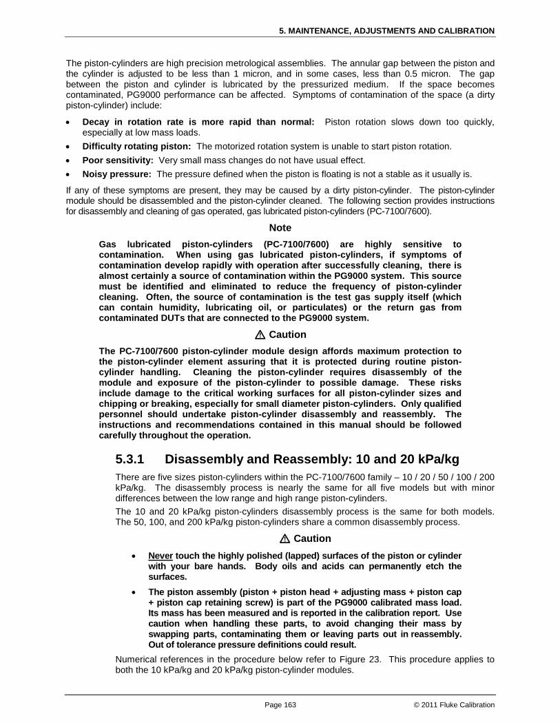
5. MAINTENANCE, ADJUSTMENTS AND CALIBRATION
Page 163 © 2011 Fluke Calibration
The piston-cylinders are high precision metrological assemblies. The annular gap between the piston and the cylinder is adjusted to be less than 1 micron, and in some cases, less than 0.5 micron. The gap between the piston and cylinder is lubricated by the pressurized medium. If the space becomes contaminated, PG9000 performance can be affected. Symptoms of contamination of the space (a dirty piston-cylinder) include:
• Decay in rotation rate is more rapid than normal: Piston rotation slows down too quickly, especially at low mass loads.
• Difficulty rotating piston: The motorized rotation system is unable to start piston rotation. • Poor sensitivity: Very small mass changes do not have usual effect. • Noisy pressure: The pressure defined when the piston is floating is not a stable as it usually is.
If any of these symptoms are present, they may be caused by a dirty piston-cylinder. The piston-cylinder module should be disassembled and the piston-cylinder cleaned. The following section provides instructions for disassembly and cleaning of gas operated, gas lubricated piston-cylinders (PC-7100/7600).
Note Gas lubricated piston-cylinders (PC-7100/7600) are highly sensitive to contamination. When using gas lubricated piston-cylinders, if symptoms of contamination develop rapidly with operation after successfully cleaning, there is almost certainly a source of contamination within the PG9000 system. This source must be identified and eliminated to reduce the frequency of piston-cylinder cleaning. Often, the source of contamination is the test gas supply itself (which can contain humidity, lubricating oil, or particulates) or the return gas from contaminated DUTs that are connected to the PG9000 system.
Caution The PC-7100/7600 piston-cylinder module design affords maximum protection to the piston-cylinder element assuring that it is protected during routine piston-cylinder handling. Cleaning the piston-cylinder requires disassembly of the module and exposure of the piston-cylinder to possible damage. These risks include damage to the critical working surfaces for all piston-cylinder sizes and chipping or breaking, especially for small diameter piston-cylinders. Only qualified personnel should undertake piston-cylinder disassembly and reassembly. The instructions and recommendations contained in this manual should be followed carefully throughout the operation.
5.3.1 Disassembly and Reassembly: 10 and 20 kPa/kg There are five sizes piston-cylinders within the PC-7100/7600 family – 10 / 20 / 50 / 100 / 200 kPa/kg. The disassembly process is nearly the same for all five models but with minor differences between the low range and high range piston-cylinders. The 10 and 20 kPa/kg piston-cylinders disassembly process is the same for both models. The 50, 100, and 200 kPa/kg piston-cylinders share a common disassembly process.
Caution • Never
• The piston assembly (piston + piston head + adjusting mass + piston cap + piston cap retaining screw) is part of the PG9000 calibrated mass load. Its mass has been measured and is reported in the calibration report. Use caution when handling these parts, to avoid changing their mass by swapping parts, contaminating them or leaving parts out in reassembly. Out of tolerance pressure definitions could result.
touch the highly polished (lapped) surfaces of the piston or cylinder with your bare hands. Body oils and acids can permanently etch the surfaces.
Numerical references in the procedure below refer to Figure 23. This procedure applies to both the 10 kPa/kg and 20 kPa/kg piston-cylinder modules.

PG9602™ OPERATION AND MAINTENANCE MANUAL
© 2011 Fluke Calibration Page 164
Place the piston-cylinder module upside down on a clean stable surface (piston cap (2) down).
Using the 10 kPa/kg side of the sleeve nut tool (see Figure 24), remove the sleeve nut (9). The sleeve nut tool is a spanner that fits into the two holes on the sleeve nut.
Step 1 and 2
Remove the O-ring assembly (8). Then, being sure to support the cylinder (7) so it doesn’t fall out, turn the remaining assembly over so that the piston cap (2) is up.
Step 3
While firmly holding down the cap (2), use a 5 mm Allen tool (supplied with PG9000 accessories), to loosen the socket head cap retaining screw (1). The cap retaining screw will not fully disengage from the piston cap due to the adjustment mass (3). Gently remove the cap and screw from the assembly.
Step 4

5. MAINTENANCE, ADJUSTMENTS AND CALIBRATION
Page 165 © 2011 Fluke Calibration
Remove the main module housing (4) by sliding it upward leaving behind the piston-cylinder assembly.
Caution Do not touch the polished surfaces of the piston or the cylinder at any time.
Step 5
Reinstall the piston cap (2) directly onto the piston head (5).
Step 6

PG9602™ OPERATION AND MAINTENANCE MANUAL
© 2011 Fluke Calibration Page 166
Place the 10 kPa/kg piston insertion tool (see Section 5.3.1.1) on the work surface with the large diameter down.
Caution Do not touch the white plastic alignment ring of the piston insertion tool. The ring will come in contact with the inside of the cylinder and could introduce cross contamination.
Note In reassembly, see Section 5.3.1.1 for instructions on using the insertion tool to put the cylinder back into the piston.
Holding the cylinder (7) to prevent it from falling off, place the piston-cylinder assembly onto the tool sliding the hollowed end of the piston (6) onto the tool shaft. Carefully allow the cylinder to drop down over the white plastic centering ring. Holding the cylinder, gently remove the piston (6) from the tool. Finally, remove the tool from the cylinder.
Step 7 and 8
To reassemble follow the steps above in reverse order. See the following section about the piston insertion tool for additional details on reassembly of the cylinder onto the piston using the piston insertion tool. Follow the notes carefully and refer to the lubrication recommendations in Section 5.3.4
Caution The orientation of the piston in the cylinder is important. In reassembly, the end of the cylinder that is marked with the serial number should go into the main module housing first. The piston enters the end of the cylinder that is marked with the serial number. Installing the cylinder with the wrong orientation may lead to out of tolerance measurements.

5. MAINTENANCE, ADJUSTMENTS AND CALIBRATION
Page 167 © 2011 Fluke Calibration
Figure 23. 10 kPa/kg piston-cylinder module (expanded view)
Figure 24. Gas piston-cylinder module sleeve nut tool
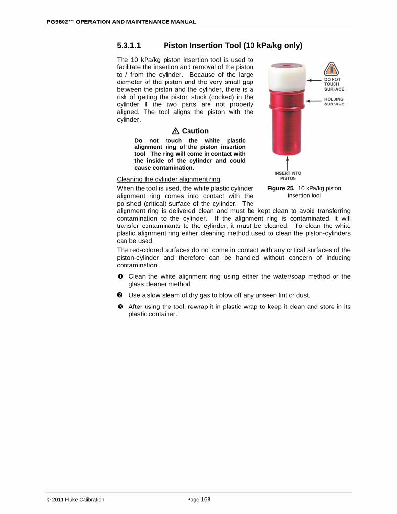
PG9602™ OPERATION AND MAINTENANCE MANUAL
© 2011 Fluke Calibration Page 168
5.3.1.1 Piston Insertion Tool (10 kPa/kg only)
The 10 kPa/kg piston insertion tool is used to facilitate the insertion and removal of the piston to / from the cylinder. Because of the large diameter of the piston and the very small gap between the piston and the cylinder, there is a risk of getting the piston stuck (cocked) in the cylinder if the two parts are not properly aligned. The tool aligns the piston with the cylinder.
Caution Do not touch the white plastic alignment ring of the piston insertion tool. The ring will come in contact with the inside of the cylinder and could cause contamination.
When the tool is used, the white plastic cylinder alignment ring comes into contact with the polished (critical) surface of the cylinder. The alignment ring is delivered clean and must be kept clean to avoid transferring contamination to the cylinder. If the alignment ring is contaminated, it will transfer contaminants to the cylinder, it must be cleaned. To clean the white plastic alignment ring either cleaning method used to clean the piston-cylinders can be used.
Cleaning the cylinder alignment ring
The red-colored surfaces do not come in contact with any critical surfaces of the piston-cylinder and therefore can be handled without concern of inducing contamination.
Clean the white alignment ring using either the water/soap method or the glass cleaner method.
Use a slow steam of dry gas to blow off any unseen lint or dust.
After using the tool, rewrap it in plastic wrap to keep it clean and store in its plastic container.
Figure 25. 10 kPa/kg piston
insertion tool

5. MAINTENANCE, ADJUSTMENTS AND CALIBRATION
Page 169 © 2011 Fluke Calibration
Installing the cylinder onto the pistonTo install the cylinder onto the piston, proceed as follows, being sure not to touch any polished surfaces of the piston or the cylinder:
Place the piston-cylinder module on a clean stable surface with the piston cap down.
Insert the red end of the insertion tool into the hollow piston. Hold the tool by the holding area; do not touch the white plastic cylinder centering ring.
Step 1 and 2
Orient the cylinder so that the end etched with the serial number is down and will meet the piston first. Gently slide the cylinder down over the white plastic cylinder centering ring, keeping it straight and aligning it with the cylinder to get it to slide down onto the cylinder.
Pick up the piston-cylinder and move the cylinder on the piston, checking that they are both clean and there is good mobility of the piston in the cylinder. Then reassemble the piston-cylinder module.
Caution The orientation of the piston in the cylinder is important. The piston enters the end of the cylinder that is marked with the serial number. Installing the cylinder with the wrong orientation may lead to out of tolerance measurements.
Step 3 and 4
5.3.2 Disassembly and Reassembly: 50, 100 and 200 kPa/kg There are five sizes piston-cylinders within the PC-7100/7600 family – 10 / 20 / 50 / 100 / 200 kPa/kg. The disassembly process is nearly the same for all five models but with minor differences between the low range and high range piston-cylinders. The 10 and 20 kPa/kg piston-cylinders disassembly and reassembly process is the same for both models. The 50, 100, and 200 kPa/kg piston-cylinders share a common disassembly process.

PG9602™ OPERATION AND MAINTENANCE MANUAL
© 2011 Fluke Calibration Page 170
Caution • Never
• The piston assembly (piston + piston head + adjusting mass + piston cap + piston cap retaining screw) is part of the PG9000 calibrated mass load. Its mass has been measured and is reported in the calibration report. Use caution when handling these parts, to avoid changing their mass by swapping parts, contaminating them or leaving parts out in reassembly. Out of tolerance pressure definitions could result.
touch the highly polished (lapped) surfaces of the piston or cylinder with your bare hands. Body oils and acids can permanently etch the surfaces.
Numerical references in the procedure below refer to Figure 26. This procedure applies to the 50 kPa/kg, 100 kPa/kg and 200 kPa/kg piston-cylinder modules.
Place the piston-cylinder module on a clean stable surface with the piston cap (2) up.
Using a 3 mm Allen tool (supplied with PG9000 accessories), loosen the two sleeve retaining socket head screws (5) from the opposing sides of the main module housing (4).
Note
In reassembly, after the two sleeve retaining screws (5) are installed, the sleeve (7) must still have a small amount of freedom to move and rotate within the main module housing (4). Do not over tighten the screws.
Step 1 and 2
While firmly holding down the cap (2), use a 5 mm Allen tool (supplied with PG9000 accessories) to loosen the socket head cap retaining screw (1). The cap retaining screw will not fully disengage from the piston cap due to the adjustment mass (3). Gently remove the cap and screw from the assembly.
Step 3
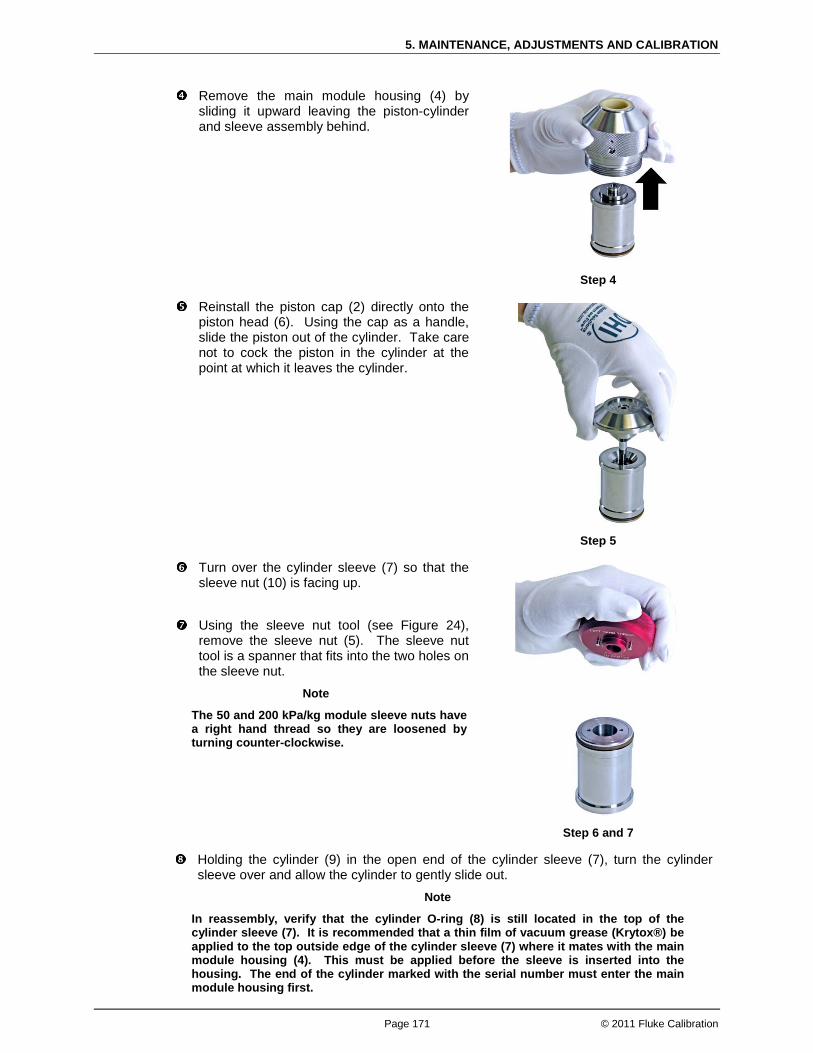
5. MAINTENANCE, ADJUSTMENTS AND CALIBRATION
Page 171 © 2011 Fluke Calibration
Remove the main module housing (4) by sliding it upward leaving the piston-cylinder and sleeve assembly behind.
Step 4
Reinstall the piston cap (2) directly onto the piston head (6). Using the cap as a handle, slide the piston out of the cylinder. Take care not to cock the piston in the cylinder at the point at which it leaves the cylinder.
Step 5
Turn over the cylinder sleeve (7) so that the sleeve nut (10) is facing up.
Step 6 and 7
Using the sleeve nut tool (see Figure 24), remove the sleeve nut (5). The sleeve nut tool is a spanner that fits into the two holes on the sleeve nut.
Note
The 50 and 200 kPa/kg module sleeve nuts have a right hand thread so they are loosened by turning counter-clockwise.
Holding the cylinder (9) in the open end of the cylinder sleeve (7), turn the cylinder sleeve over and allow the cylinder to gently slide out.
Note
In reassembly, verify that the cylinder O-ring (8) is still located in the top of the cylinder sleeve (7). It is recommended that a thin film of vacuum grease (Krytox®) be applied to the top outside edge of the cylinder sleeve (7) where it mates with the main module housing (4). This must be applied before the sleeve is inserted into the housing. The end of the cylinder marked with the serial number must enter the main module housing first.

PG9602™ OPERATION AND MAINTENANCE MANUAL
© 2011 Fluke Calibration Page 172
Caution
In reassembly, the two sleeve retaining screws (5) MUST be reinstalled before pressure is applied to the piston-cylinder module. Damage to equipment and injury to personnel may result from pressurizing the piston-cylinder module without the sleeve retaining screws installed.
To reassemble follow the steps above in reverse order. Follow the notes carefully and refer to the lubrication recommendations in Section 5.3.4.
Figure 26. 50, 100 and 200 kPa/kg gas piston-cylinder modules (exploded view)
5.3.3 Cleaning Piston-Cylinders There are two general methods for cleaning a piston-cylinder. They are a water / detergent method, or a quicker method using Windex® brand (or equivalent) glass cleaner.
Caution • Never
• Do not undertake piston-cylinder module disassembly without familiarizing yourself with Section 5.3.1 of this manual. Incorrect disassembly may damage or destroy the piston-cylinder element.
touch the lapped surfaces (polished appearance) of the piston or cylinder with your bare hands. Body oils and acids can permanently etch the surfaces.
5. MAINTENANCE, ADJUSTMENTS AND CALIBRATION
Page 173 © 2011 Fluke Calibration
5.3.3.1 Water / Detergent Cleaning method: Of the two cleaning methods, the water/detergent method is more time consuming but more thorough.
Disassemble the piston-cylinder module. Reinstall the cap on the piston and insert the piston into the cylinder. Create a bath of water and mild liquid dishwashing detergent. Distilled
water is acceptable. De-ionized water is best. Detergent must be free of additives (i.e., lotions or softening agents which may leave a residue after cleaning). To avoid undesired thermal effects, bring the bath to room temperature.
Holding the piston-cylinder assembly by the outside of the cylinder and the piston cap, submerge the assembly in the bath. Using a rotating motion, thoroughly work the detergent into the piston-cylinder assembly.
With the piston-cylinder still assembled, thoroughly rinse the assembly in a bath of water only. Use the same rotating motion as in the previous step.
Remove the piston from the cylinder and thoroughly dry all areas of the assembly using a paper towel. DO NOT touch the critical lapped surfaces of the piston or the cylinder with anything other than the drying wipe. Use only one side of the wipe during this process as the other side will become contaminated by contact with the operator’s hands. Just dry thoroughly.
Test the mobility of the piston in the cylinder by simultaneously moving the piston in and out of the cylinder and rotating them one relative to the other. The piston should feel perfectly free, like an air bearing, with no evidence of mechanical contact. If it does not, back up in the cleaning process. If the assembly temperature was elevated during cleaning, it may be necessary to wait to allow the temperature of the assembly to return to ambient temperature before the assembly will operate normally. With experience, the difference in feel between a piston-cylinder that is truly clean, and one that is mildly contaminated, becomes obvious.
Reassemble the piston-cylinder module.
5.3.3.2 Quick Method: Of the two cleaning methods, the quick method is less demanding, but potentially less thorough. However, it is a recommended method based on efficiency of time and end results.
Disassemble the piston-cylinder module. Reinstall the cap on the piston – use it as a handle for manipulating the piston. Apply a small amount of Windex® brand glass cleaner to a paper towel.
Wipe the lapped surfaces (polished appearance) of both the piston and cylinder with the cleaner. Let the piston and cylinder dry.
Using a separate, clean paper towel, wipe the surfaces again to remove the dry Windex® residue. Finish by blowing the surfaces off with a slow flow of compressed nitrogen.
Test the mobility of the piston in the cylinder by simultaneously moving the piston in and out of the cylinder and rotating them one relative to the other. They should feel perfectly free, like an air bearing, with no evidence of mechanical contact. If there is any feel of resistance or friction, back up in the cleaning process. If the assembly temperature was elevated during cleaning, it may be necessary to wait to allow the temperature of the assembly to return to ambient temperature before the assembly will operate normally. With experience, the difference in feel between a piston-cylinder that is truly clean, and one that is even mildly contaminated, becomes obvious.
Reassemble the piston-cylinder module.

PG9602™ OPERATION AND MAINTENANCE MANUAL
© 2011 Fluke Calibration Page 174
5.3.4 Lubricating Piston-Cylinder Modules The purpose of piston-cylinder module lubrication is to minimize wear to components of the piston-cylinder module. The proper long term functioning of the module requires that specific areas of certain components be properly lubricated, especially after they have been cleaned. Of main concern is lubrication of the threads on the outside of the piston-cylinder module. This interacts with the threaded mounting post and represents potential for galling if not properly lubricated. This critical area is highlighted with a red circle.
Lubricant Vacuum Grease: DuPont Krytox® GPL-205/6 is the recommended lubricant. Krytox® is selected because it is a non-reactive, nonflammable, hydrocarbon free grease. Very small amounts are used. Krytox® is made of perfluoropolyether (PFPE) thickened with polytetrafluoroethylene (PTFE). Users should avoid contact with eyes and skin. A tube of Krytox GPL-205/6 is included in the PG9000 accessory kit.
Where to lubricate The lubrication image below shows the areas that require application of lubricant. A thin film (i.e. just enough lubricant to fully cover the area indicated) applied to these areas is all that is necessary. Lubrication with more than a thin film will increase the cost of lubrication and may result in contamination of the piston and/or cylinder. Areas not indicated for lubrication should be kept free of lubricant.
Note Under application of a hard and prolonged vacuum, the risk increases for vacuum grease to migrate away from the surface it was applied and potentially get deposited on the critical surfaces of the piston-cylinder.
The principle area to lubricate is the threads on the outside of the piston-cylinder housing (referred to as the NUT in the diagram below). A couple dabs of lubricant spread around the perimeter of the threads will help minimize the potential for metal galling which could prevent the removal of the piston-cylinder module from the mounting post.
Lubricating O-rings The o-rings typically do not require lubrication. The intent is to keep the polymers from drying out and cracking. Periodically inspect the o-rings to ensure they remain pliable and free of cracks. If lubrication is required, the process is to remove the o-ring, coat with Krytox, then wipe away all excess lubricant with a paper towel. The idea is to leave behind a micro-thin film.
Pistons and cylinders Pistons and cylinders should be kept perfectly free from vacuum grease and any other contaminant. Vacuum grease or other contaminants on the piston or cylinder will prevent the piston-cylinder from operating correctly.
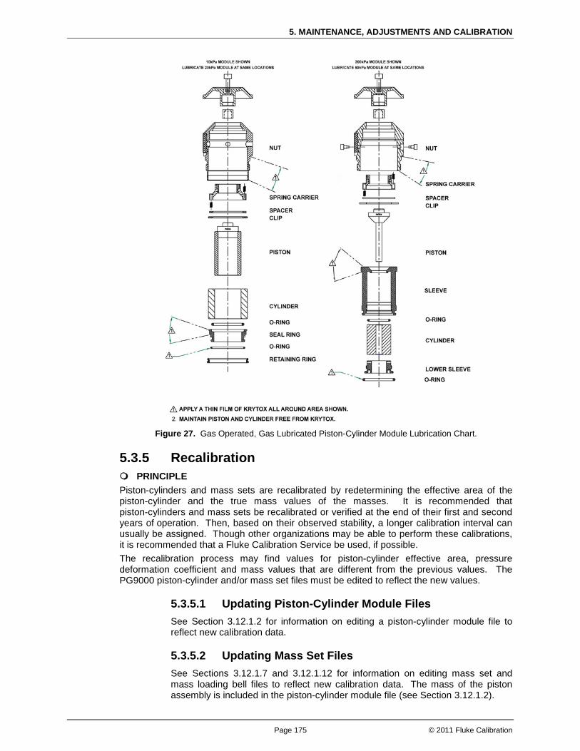
5. MAINTENANCE, ADJUSTMENTS AND CALIBRATION
Page 175 © 2011 Fluke Calibration
Figure 27. Gas Operated, Gas Lubricated Piston-Cylinder Module Lubrication Chart.
5.3.5 Recalibration PRINCIPLE Piston-cylinders and mass sets are recalibrated by redetermining the effective area of the piston-cylinder and the true mass values of the masses. It is recommended that piston-cylinders and mass sets be recalibrated or verified at the end of their first and second years of operation. Then, based on their observed stability, a longer calibration interval can usually be assigned. Though other organizations may be able to perform these calibrations, it is recommended that a Fluke Calibration Service be used, if possible. The recalibration process may find values for piston-cylinder effective area, pressure deformation coefficient and mass values that are different from the previous values. The PG9000 piston-cylinder and/or mass set files must be edited to reflect the new values.
5.3.5.1 Updating Piston-Cylinder Module Files See Section 3.12.1.2 for information on editing a piston-cylinder module file to reflect new calibration data.
5.3.5.2 Updating Mass Set Files See Sections 3.12.1.7 and 3.12.1.12 for information on editing mass set and mass loading bell files to reflect new calibration data. The mass of the piston assembly is included in the piston-cylinder module file (see Section 3.12.1.2).

PG9602™ OPERATION AND MAINTENANCE MANUAL
© 2011 Fluke Calibration Page 176
5.4 Mass Sets
5.4.1 Cleaning Care should always be taken with all PG9000 masses, including the piston assembly and the mass loading bell, to avoid contaminating them with liquids or particles. They should never be handled with bare hands. Over time, or by an accidental incident, masses may become soiled. In these cases, they can be cleaned. Masses should be cleaned with a non-abrasive general purpose cleaner (such as glass cleaner) and wiped dry with lint free paper towels.
Note Cleaning masses can change mass values. If knowledge of as received condition of the masses is required then masses should be cleaned after as received mass determination is taken and before as left mass determination.
5.4.2 Recalibration See Section 5.3.5.
5.5 Updating Embedded Software for PG9000 PG9000 uses FLASH memory. This allows the embedded software that controls PG9000 operations and functions to be written to the PG9000 over its COM1 port from a computer using the WinFlashTM utility program.
To replace corrupted software or upgrade your software, two pieces are required – the binary software file for PG9600 and the WinFlashTM utility. Both files are available for download from www.flukecal.com – from the “Service and Support” link. Be careful that the “PG7000 / PG9000” package is used as “PG7000” by itself is only for the older revisions of the PG7000 family of piston gauges.
Note • Do not power down the PG9000 while upgrading the software. Only
upgrade software to a newer version. Never backwards flash to an earlier version unless explicitly instructed to do so. After the upgrade, a message on the PG9000 terminal may indicate “PL REPROGRAMMING! TAKES 30 SEC”. Do not power down while this message is displayed. A message will follow instructing when programming is complete to cycle the PG9000 power.
• The Fluke Calibration flash software loading utility and PG9000 embedded software are available for download from the Service and Support section of Fluke Calibration’s worldwide web site at www.flukecal.com.
5.6 Disassembly and Reassembly of PG9000
5.6.1 Platform Disassembly of the PG9600 platform is minimal and consists of loosening a few screws from the bottom to access the PRTs and removing screws to access the piston drive belts. See Section 5.2.1.5, Piston-Cylinder Module Temperature Sensors and Section 5.2.3 for instructions.

5. MAINTENANCE, ADJUSTMENTS AND CALIBRATION
Page 177 © 2011 Fluke Calibration
5.6.2 Terminal For routine maintenance, there is not a requirement to open the PG Terminal. The power supply fuse is located in the power entry module and has a pull out fuse tray that is accessible from the outside of the PG Terminal. To open the PG9000 Terminal proceed as follows: Disconnect power. Remove the pop-off screw covers on the bottom of the case. Remove the four case screws. Lift OFF the cover. Be careful not to over stress the ribbon cables connecting the display
and keypad in the cover to the printed circuit board in the base. Disconnect the cover to base ribbon cables at the connectors on the base printed
circuit board. Be aware that the connectors are locking connectors. To reassemble, proceed in reverse order.
5.6.3 AMH Removal To remove the AMH-100-VAC from the PG9000 Platform, see Section 3.7.2.2.

PG9602™ OPERATION AND MAINTENANCE MANUAL
© 2011 Fluke Calibration Page 178
Notes
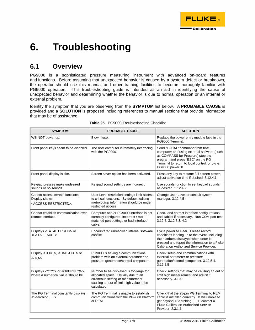
Page 179 © 1998-2010 Fluke Calibration
6. Troubleshooting
6.1 Overview PG9000 is a sophisticated pressure measuring instrument with advanced on-board features and functions. Before assuming that unexpected behavior is caused by a system defect or breakdown, the operator should use this manual and other training facilities to become thoroughly familiar with PG9000 operation. This troubleshooting guide is intended as an aid in identifying the cause of unexpected behavior and determining whether the behavior is due to normal operation or an internal or external problem.
Identify the symptom that you are observing from the SYMPTOM list below. A PROBABLE CAUSE is provided and a SOLUTION is proposed including references to manual sections that provide information that may be of assistance.
Table 25. PG9000 Troubleshooting Checklist
SYMPTOM PROBABLE CAUSE SOLUTION
Will NOT power up. Blown fuse. Replace the power entry module fuse in the PG9000 Terminal.
Front panel keys seem to be disabled. The host computer is remotely interfacing with the PG9000.
Send “LOCAL” command from host computer; or if using external software (such as COMPASS for Pressure) stop the program and press “ESC” on the PG Terminal to return to local control; or cycle PG9000 power. 0
Front panel display is dim. Screen saver option has been activated. Press any key to resume full screen power, adjust activation time if desired. 3.12.4.1
Keypad presses make undesired sounds or no sounds.
Keypad sound settings are incorrect. Use sounds function to set keypad sounds as desired. 3.12.4.2
Cannot access certain functions. Display shows: <ACCESS RESTRICTED>.
User Level restriction settings limit access to critical functions. By default, editing metrological information should be under restricted access.
Change User Level or consult system manager. 3.12.4.5
Cannot establish communication over remote interface.
Computer and/or PG9000 interface is not correctly configured; incorrect / mis-matched port settings or bad interface cable.
Check and correct interface configurations and cables if necessary. Run COM port test. 3.12.5, 3.12.5.3, 4.2
Displays <FATAL ERROR> or <FATAL FAULT>.
Encountered unresolved internal software conflict.
Cycle power to clear. Please record conditions leading up to the event, including the numbers displayed when enter is pressed and report the information to a Fluke Calibration Authorized Service Provider.
Display <TOUT>, <TIME-OUT> or <-TO->
PG9000 is having a communications problem with an external barometer or pressure generation/control component.
Check setup and communications with external barometer or pressure generation/control component. 3.12.5.4, 3.12.5.5
Displays <******> or <OVERFLOW> where a numerical value should be.
Number to be displayed is too large for allocated space. Usually due to an erroneous setting or measurement causing an out of limit high value to be calculated.
Check settings that may be causing an out of limit high measurement and adjust if necessary. 3.10.3
The PG Terminal constantly displays <Searching …. >.
The PG Terminal is unable to establish communications with the PG9000 Platform or REM.
Check that the 25-pin PG Terminal to REM cable is installed correctly. If still unable to get beyond <Searching …. >, contact a Fluke Calibration Authorized Service Provider. 2.3.1.1

PG9602™ OPERATION AND MAINTENANCE MANUAL
© 2011 Fluke Calibration Page 180
SYMPTOM PROBABLE CAUSE SOLUTION
The run screen is not the normal MAIN run screen.
You are in the SYSTEM or AMBIENT run screen.
Operation is normal. Press [ESC] to return, may need to press several times. 3.8
Displays of ambient conditions values are not accurate.
The reference to which the ambient condition values are being compared is not accurate or the specifications of the ambient conditions sensors are not being evaluated correctly.
Check the specifications and operation of the reference being used for ambient conditions. Consider the specifications of the ambient conditions measurements. 1.2.1.3
Another Setup file, other than Setup file #1, is being used and configured with alternate settings.
Select Setup file #1. 3.11.1
On power up, PG Terminal displays <RH Sensor ERR#xx> or PRT or RH field displays flashing <ERR>
TH Probe is not connected Turn power off. Check TH Probe connection. Turn power on. 2.3.1.1
Piston drop rate is excessive. There is a leak in the pressurized system or the device under test itself.
Correct leak.
You’re working with high pressure and the adiabatic effects are inducing an initial rapid drop in pressure.
Continue to make slight adjustments to the piston float position until the adiabatic effects settle out.
Piston rotation rate decay rate is excessive.
Piston position detection is out of adjustment is piston is in spring zone, not floating freely.
Adjust piston position detection. 5.2.2
Piston-cylinder is dirty – most evident at low mass loads.
Clean the piston-cylinder. 5.3.3
Motorized rotation will not engage. Motorized rotation system recovering from overload or the measurement is absolute by vacuum and reference vacuum is not low enough.
Wait 25 seconds for system to recover. 3.10.13, 3.10.8 P Gen and rotation will not engage until the reference vacuum is ready.
Automated motorized rotation is not operating.
Automated motorized rotation is OFF. Press [ROTATE] and enable the feature. 3.10.8
Manually activated motorized rotation cutoff while the [ ] was still pressed.
Motorized rotation has overloaded or maximum rotation rate was reached.
Operation is normal. Wait 25 seconds for system to recover from overload or wait until rotation rate is below maximum. 3.10.8
Automated motorized rotation is not engaging even though rotation rate is less than minimum Ready rotation rate.
Current mass load is under cutoff load of 3 kg.
Operation is normal. 3.4.2 At low mass loads the minimum limit is reduced to maximize rotation time.
Motorized rotation unable to start piston rotation.
Possible combination of a large mass load, a dirty piston-cylinder, and polished drive belts.
Clean piston-cylinder. 5.3.3 Clean or replace drive belts. 5.2.3
The piston deceleration function starts immediately when [ENT/SET P] is pressed.
Operation is normal but can be modified so that deceleration does not occur if it is not needed.
Turn off the PRE-DECEL function. 3.10.8.1
Piston rotation rate slows down too quickly; motorized rotation engages too frequently.
Piston-cylinder dirty, PG9000 Platform not level, PG9000 subjected to excessive vibration.
Clean piston-cylinder, level PG9000 Platform, adjust piston position indication, remove sources of vibration. 2.3.1.1, Error! Reference source not found.
Piston position indication is not properly calibrated and piston is not floating when rotation engages – trying to rotate when still in the spring zone.
Calibrate piston position indication system. 5.2.2. Figure 14
The mass value loading instruction resulting from a pressure entry and the mass value displayed in the MAIN run screen are not the same.
Mass entries are in nominal mass and MAIN run screen displays actual mass.
Operation is normal. Review PG9000 mass protocol. 3.6
The resolution of mass loading instructions doesn’t seem correct.
The mass loading resolution setting is set incorrectly.
Use [RES] to set mass loading resolution as desired. 3.10.10 The recommended default setting is 0.1 kg.
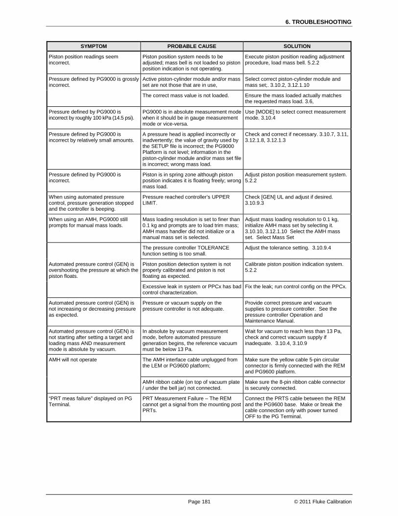
6. TROUBLESHOOTING
Page 181 © 2011 Fluke Calibration
SYMPTOM PROBABLE CAUSE SOLUTION
Piston position readings seem incorrect.
Piston position system needs to be adjusted; mass bell is not loaded so piston position indication is not operating.
Execute piston position reading adjustment procedure, load mass bell. 5.2.2
Pressure defined by PG9000 is grossly incorrect.
Active piston-cylinder module and/or mass set are not those that are in use,
Select correct piston-cylinder module and mass set;. 3.10.2, 3.12.1.10
The correct mass value is not loaded. Ensure the mass loaded actually matches the requested mass load. 3.6,
Pressure defined by PG9000 is incorrect by roughly 100 kPa (14.5 psi).
PG9000 is in absolute measurement mode when it should be in gauge measurement mode or vice-versa.
Use [MODE] to select correct measurement mode. 3.10.4
Pressure defined by PG9000 is incorrect by relatively small amounts.
A pressure head is applied incorrectly or inadvertently; the value of gravity used by the SETUP file is incorrect; the PG9000 Platform is not level; information in the piston-cylinder module and/or mass set file is incorrect; wrong mass load.
Check and correct if necessary. 3.10.7, 3.11, 3.12.1.8, 3.12.1.3
Pressure defined by PG9000 is incorrect.
Piston is in spring zone although piston position indicates it is floating freely; wrong mass load.
Adjust piston position measurement system. 5.2.2
When using automated pressure control, pressure generation stopped and the controller is beeping.
Pressure reached controller’s UPPER LIMIT.
Check [GEN] UL and adjust if desired. 3.10.9.3
When using an AMH, PG9000 still prompts for manual mass loads.
Mass loading resolution is set to finer than 0.1 kg and prompts are to load trim mass; AMH mass handler did not initialize or a manual mass set is selected.
Adjust mass loading resolution to 0.1 kg, initialize AMH mass set by selecting it. 3.10.10, 3.12.1.10 Select the AMH mass set. Select Mass Set
Automated pressure control (GEN) is overshooting the pressure at which the piston floats.
The pressure controller TOLERANCE function setting is too small.
Adjust the tolerance setting. 3.10.9.4
Piston position detection system is not properly calibrated and piston is not floating as expected.
Calibrate piston position indication system. 5.2.2
Excessive leak in system or PPCx has bad control characterization.
Fix the leak; run control config on the PPCx.
Automated pressure control (GEN) is not increasing or decreasing pressure as expected.
Pressure or vacuum supply on the pressure controller is not adequate.
Provide correct pressure and vacuum supplies to pressure controller. See the pressure controller Operation and Maintenance Manual.
Automated pressure control (GEN) is not starting after setting a target and loading mass AND measurement mode is absolute by vacuum.
In absolute by vacuum measurement mode, before automated pressure generation begins, the reference vacuum must be below 13 Pa.
Wait for vacuum to reach less than 13 Pa, check and correct vacuum supply if inadequate. 3.10.4, 3.10.9
AMH will not operate The AMH interface cable unplugged from the LEM or PG9600 platform;
Make sure the yellow cable 5-pin circular connector is firmly connected with the REM and PG9600 platform.
AMH ribbon cable (on top of vacuum plate / under the bell jar) not connected.
Make sure the 8-pin ribbon cable connector is securely connected.
“PRT meas failure” displayed on PG Terminal.
PRT Measurement Failure – The REM cannot get a signal from the mounting post PRTs.
Connect the PRTS cable between the REM and the PG9600 base. Make or break the cable connection only with power turned OFF to the PG Terminal.

PG9602™ OPERATION AND MAINTENANCE MANUAL
© 2011 Fluke Calibration Page 182
Notes

Page 183 © 1998-2010 Fluke Calibration
7. Appendix
7.1 Conversion Of Numerical Values PG9000 performs all internal calculations in SI units. Numerical values input or output in other units are converted to SI immediately after entry and back to other units just before output as needed.
Table 26 provides the conversion coefficients used by PG9000 to convert numerical values expressed in SI units to corresponding values expressed in other units.
7.1.1 Pressure Table 26. Pressure Unit of Measure Conversions
To convert from Pa to Multiply by
Pa Pascal 1.0
mbar millibar 1.0 E-02
kPa kilo Pascal 1.0 E-03
bar Bar 1.0 E-05
mmWa @ 4°C millimeter of water 1.019716 E-01
mmHg @ 0°C millimeter of mercury 7.50063 E-03
psi pound per square inch 1.450377 E-04
psf pound per square foot 0.0208854
inWa @ 4°C inch of water 4.014649 E-03
inWa @ 20°C inch of water 4.021732 E-03
inWa @ 60°F inch of water 4.018429 E-03
inHg @ 0°C inch of mercury 2.953 E-04
kcm2 kilogram force per centimeter square 1.019716 E-05
Torr Torr (mmHg @ 0°C) 7.50063 E-03
mTor milli Torr (micron Hg @ 0°C) 7.50063
user User User defined coefficient

PG9602™ OPERATION AND MAINTENANCE MANUAL
© 2011 Fluke Calibration Page 184
7.2 Defined Pressure Calculations Sections 7.2.1 and 7.2.2 document the calculations used by PG9000 piston gauges to obtain the defined pressure.
Table 27 defines the pressure calculation variables used in Sections 7.2.1 and 7.2.2. Table 27. PG9000 Defined Pressure Calculation Variables
VARIABLE DEFINITION UNITS SOURCE OF VALUE
/πΑ Pθ , Piston radius at temperature θ and pressure P
m Calculated.
A20,0 Piston effective area at 20°C, Patm mm2 Piston-cylinder module file (3.12.1.3). Aθ,P Piston effective area at temperature θ,
pressure P m2 Calculated from A20,0 in piston-cylinder
module file (3.12.1.3). G Local gravity m/s2 Local, standard or user as specified in
current SETUP file (3.11, 3.12.6). KN Nominal mass-to-pressure conversion
coefficient for a given piston-cylinder size Pa/kg Calculated from A20,0 and standard
conditions. M Mass load kg Current mass loading instruction (3.6,
3.10.11). PA Absolute pressure Paa Calculated. Patm Atmospheric (ambient) pressure Paa Internal measurement, user entered value
or standard as specified by SETUP file (3.11). PG Gauge pressure Pa Calculated. PHA Fluid head correction in absolute mode Pa Calculated using device heights and
medium (7.2.2, 3.10.7, 3.12.3). PHG Fluid head correction in gauge mode Pa Calculated using device heights and
medium (7.2.2, 3.10.7, 3.12.3). Pnom Nominal pressure Pa In pressure-to-mass mode Pnom=Preq
In mass-to-pressure mode Pnom=M·KN Poffset Difference between PG9000 and RPM at
the static pressure of differential mode Pa Determined experimentally in PG9000
differential mode operation (see Section 3.10.4.1, Selecting Differential Mode, Setting Static Pressure, Finding RPM Offset (<1run>)
PRPM
. Current static pressure reading from reference pressure monitor
Paa Read automatically from external atm P source specified by SETUP file. Used in differential mode only (3.11, 3.10.4.1).
∆PD Differential pressure Pa Calculated. Differential mode only (3.10.4.1).
Γ Surface tension coefficient N/m Piston-cylinder module file (3.12.1.3). αC Cylinder linear thermal expansion coefficient °C-1 Piston-cylinder module file (3.12.1.3). αP Piston linear thermal expansion coefficient °C-1 Piston-cylinder module file (3.12.1.3). λ Piston-cylinder pressure coefficient Pa-1 Piston-cylinder module file (3.12.1.3). θ Temperature of piston-cylinder °C Internal measurement, user entered value
or standard as specified by SETUP file (3.11). ρa Air density kg/m3 Calculated from standard air density
corrected for actual atmospheric pressure, ambient temperature and relative humidity (atm p, humidity and temp source are specified by SETUP file) (3.11).
ρm Mass density kg/m3 Mass set file (3.12.1.8).
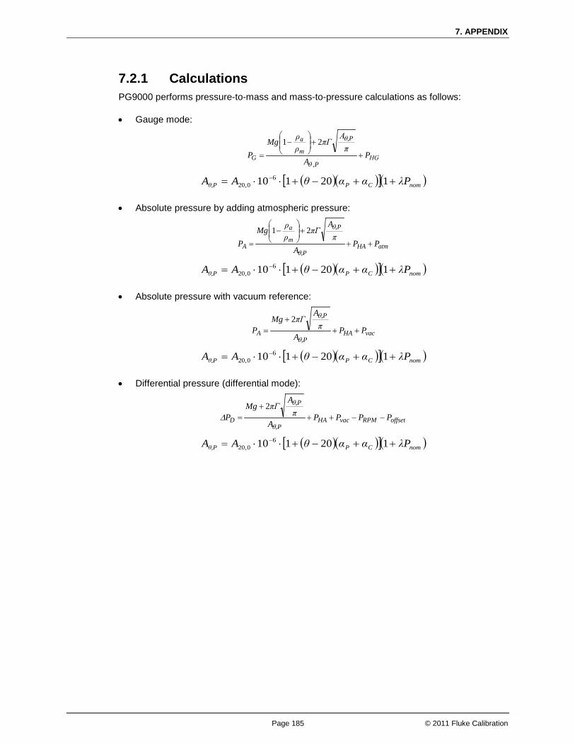
7. APPENDIX
Page 185 © 2011 Fluke Calibration
7.2.1 Calculations PG9000 performs pressure-to-mass and mass-to-pressure calculations as follows:
• Gauge mode:
ΗGP,
,P
m
a
G PA
πΑ
πΓρρMg
P +
+
−
=θ
θ21
( )( )[ ]( )nomCP,Pθ PλααθAA ++−+⋅⋅= − 120110 60,20
• Absolute pressure by adding atmospheric pressure:
atmHA,P
,P
m
a
A PPA
πA
πΓρρMg
P ++
+
−
=θ
θ21
( )( )[ ]( )nomCP,Pθ PλααθAA ++−+⋅⋅= − 120110 60,20
• Absolute pressure with vacuum reference:
vacHA,P
,P
A PPA
πA
πΓMgP ++
+=
θ
θ2
( )( )[ ]( )nomCP,Pθ PλααθAA ++−+⋅⋅= − 120110 60,20
• Differential pressure (differential mode):
offsetRPMvacHA,P
,P
D PPPPA
πA
πΓMgP −−++
+=
θ
θ
∆2
( )( )[ ]( )nomCP,Pθ PλααθAA ++−+⋅⋅= − 120110 60,20

PG9602™ OPERATION AND MAINTENANCE MANUAL
© 2011 Fluke Calibration Page 186
7.2.2 Fluid Heads
7.2.2.1 Fluid Head Components PG9000 supports three different fluid head components (see Sections 3.12.3, 3.10.7): DUT head, ATM head and Piston head. The three components are combined to create the overall head correction for each PG9000 measurement mode (see Section 7.2.2.2).
DUT head: Calculates and applies a fluid head correction to predict the defined pressure at a level other than the PG9000’s reference level (see Section 3.10.7). The DUT head is calculated following:
( ) DafH ghPDUT
ρρ −=
Where:
DUTHP , DUT head [Pa] = fluid head correction applied to the defined pressure
calculated at the PG9000 reference level.
ρ f, fluid density [kg/m3] = density of the pressurized medium (oil density = 916 kg/m3, water density = 998.2321 kg/m3, gas densities are calculated for N2, He or air dependent on current pressure and temperature).
ρ a, air density [kg/m3] = density of ambient air calculated using current ambient pressure, temperature and relative humidity (values as specified in the active SETUP file, see Section 3.11). Assumed to be zero when operating in absolute with a vacuum reference mode. Calculated using static pressure density measured by RPM in differential mode.
g, gravity [m/s2] = acceleration due to gravity (value as specified in the active SETUP file, see Section 3.11).
hD, DUT height [m] = Height of DUT above PG9000 reference level. Value is negative if below reference level.
ATM head: Calculates and applies a fluid head correction to internal or external barometer readings to correct the atmospheric pressure value to the PG9000’s reference level if the barometer is reading at a different level (see Section 3.12.3). The ATM head is calculated following:
BasH ghρPatm
=
Where:
atmHP , ATM head [Pa] = fluid head correction applied to the internal or external
barometer reading.
ρas, air density [kg/m3] = standard air density of 1.2 kg/m3.
g, gravity [m/s2] = acceleration due to gravity (value as specified in the active SETUP file, see Section 3.11).
hB, barometer height [m] = Height of the internal or external barometer above the PG9000 reference level. Value is negative if below reference level.

7. APPENDIX
Page 187 © 2011 Fluke Calibration
PISTON head: Calculates and applies a fluid head correction to compensate for the difference between the current piston position and the PG9000’s reference level (see Section 3.12.3.4). The Piston head is calculated following:
( ) ( )rloPafH hhgPP
+−= ρρ
Where:
PHP , Piston head [Pa] = fluid head correction applied to calculate defined
pressure.
ρ f, fluid density [kg/m3] = Density of test fluid at current pressure.
ρ a, air density [kg/m3] = density of ambient air calculated using current ambient pressure, temperature and relative humidity (values as specified in the active SETUP file, see Section 3.11). Assumed to be zero when operating in absolute with a vacuum reference mode. When using PG Differential mode, calculated using static pressure density measured by the Diff. Mode reference pressure monitor.
g, gravity [m/s2] = acceleration due to gravity (value as specified in the active SETUP file, see Section 3.11).
hP, piston height [m] = Height of the current piston position above PG9000 reference level (0.0 mm).
hrlo,reference level offset [m] = Reference level offset of the piston (see Section 3.10.7).
7.2.2.2 Overall Fluid Head Correction The overall fluid head correction for each PG9000 mode results from combining the three head components. In general, overall head correction is given by:
PatmDUT HHHH PPPP +−−=
Gauge mode: ( ) ( ) ( )rloPafDafHG hhgghP +−+−−= ρρρρ
Absolute mode by adding atmospheric pressure: Air density is zero for all components except for the ATM head which is used to compensate for barometer height.
( )rloPfBasDfHA hhgghghP ++−−= ρρρ
Absolute mode with vacuum reference: Air density is zero for all terms and no barometer is used.
( )rloPfDfHA hhgghP ++−= ρρ
Differential mode: Head correction is the same as for absolute mode with vacuum reference. Head correction for the height of the RPM is unnecessary through the use of the RPM offset.
( )rloPfDfHA hhgghP ++−= ρρ

PG9602™ OPERATION AND MAINTENANCE MANUAL
© 2011 Fluke Calibration Page 188
7.3 Glossary Absolute As in absolute pressure. Pressure expressed relative to vacuum.
Absolute by vacuum, avac
Absolute pressure determined by defining pressure relative to vacuum in an evacuated bell jar.
Absolute by atmosphere, aatm
Absolute pressure determined by adding atmospheric pressure to gauge pressure.
Adder A value added to internal sensor readings to offset the reading (pressure adder, temperature adder, humidity adder, vacuum adder) for calibration adjustment.
Ae Piston-cylinder effective area.
AMH Automated Mass Handling system. Sometimes written as “AMH-100” to denote an AMH capable of operating with up to a 100 kg mass set.
ATM Head Pressure head correction to the barometer measurement to take into consideration the difference between the actual barometer height and the PG9000 reference level.
Crossfloat Process of comparison of two piston cylinders in which they are connected together under pressure and the mass of one is adjusted so that both pistons float together at a common pressure.
Default The initial value of a quantity in the PG9000 that may be changed by the user. A value entered or created for a standard configuration or on power up.
Differential As in differential pressure – all pressure is by definition a differential between two values. Specifically to PG9000 operating modes, it is pressure expressed relative to atmospheric or another static pressure determined by subtracting the static pressure from absolute by vacuum (differential measurement mode).
DUT (Device Under Test)
The device being tested or calibrated. Synonymous with UUT or TI.
DUT Head Fluid head correction to the pressure defined by PG9000 to predict the pressure at the level of the DUT, which may be different from the PG9000 reference level.
FS (Full Scale) The full scale value is the maximum value of a measurement range. Limits and specifications are often expressed as % FS.
g, gl Acceleration due to gravity (g). Acceleration due to gravity at location of use (gl). The accelerational pull of gravity varies from one location to another.
Gauge As in gauge pressure. Pressure expressed relative to atmospheric pressure.
He Helium gas.
Head Fluid head, a pressure difference due to a difference in height. See also ATM head, DUT head and PISTON head.
HSTOP, LSTOP High stop and Low stop, piston maximum end of stroke positions.
InHg Pressure unit of measure, inches of mercury.
InWa Pressure unit of measure, inches of water.
kcm2 Pressure unit of measure, kilogram per centimeter square.
Measurement Mode Mode in which PG9000 is defining pressures. These include gauge (pressure relative to atmospheric pressure), absolute by atmosphere (pressure relative to vacuum but determined by adding atmospheric pressure to gauge pressure), absolute by vacuum (pressure relative to vacuum determined by establishing a vacuum around the mass load), differential (pressure relative to atmospheric or another static pressure determined by subtracting the static pressure from absolute by vacuum).
MS (Mass Set) A group of masses composed for use with a PG9000 piston gauge. There are two types: Manual and AMH.
Mass Bell The sleeve loaded onto the piston to carry other masses.
Mass Entry Mode (mass-to-pressure)
Operating mode in which the user enters the mass loaded on the piston and the PG9000 calculates the defined pressure. See also Pressure Entry Mode.
Medium, pressurized The pressurized fluid.
Multiplier A value by which internal sensor readings are multiplied to change their slope (pressure multiplier, temperature multiplier, humidity multiplier, vacuum multiplier) for calibration adjustment.

7. APPENDIX
Page 189 © 2011 Fluke Calibration
N2 Nitrogen gas.
Nominal Mass The mass loaded on the piston in terms of the nominal values as indicated on the individual masses. See also True Mass.
Normal A conventional or standard value.
PC, P-C, P/C Piston-Cylinder, piston-cylinder module.
Pressure Entry Mode (pressure-to-mass)
Operating mode in which the user enters the pressure to be defined and PG9000 calculates the mass to load. See also Mass entry mode.
PISTON head Fluid head correction based on the difference between the piston’s current position and the reference level.
PRT Platinum Resistance Thermometer. The devices used in the piston-cylinder mounting post to measure the temperature of the piston-cylinder.
Ready/Not Ready Indication of when conditions are present to make in tolerance pressure definitions based on specific criteria for each condition. Parameters include piston float position, rotation rate, correct reference vacuum when applicable.
Reference Level Height at which pressures are defined. PG9000 defines pressures at its reference level (bottom of piston when at mid-float, 0.0 mm). Fluid head corrections correct the pressure relative to the reference level.
SETUP file A configuration file specifying the source of values for the variables used by PG9000 to calculate defined pressure.
Static Pressure Pressure on the low side in PG9000 differential mode.
True Mass The actual mass loaded on the piston using the measured value of each mass. See also Nominal Mass.
User Level Level of security that can be set to limit access to certain PG9000 functions. Commonly used to protect against accidental or unauthorized editing of the metrological data.
PG9602™ OPERATION AND MAINTENANCE MANUAL
© 2011 Fluke Calibration Page 190
7.4 Limited Warranty and Limitation of Liability Each Fluke product is warranted to be free from defects in material and workmanship under normal use and service. The warranty period is one year and begins on the date of shipment. Parts, product repairs and services are warranted for 90 days. This warranty extends only to the original buyer or end-user customer of a Fluke authorized reseller, and does not apply to fuses, disposable batteries or to any product which, in Fluke's opinion, has been misused, altered, neglected, contaminated, or damaged by accident or abnormal conditions of operation or handling. Fluke warrants that software will operate substantially in accordance with its functional specifications for 90 days and that it has been properly recorded on non-defective media. Fluke does not warrant that software will be error free or operate without interruption.
Fluke authorized resellers shall extend this warranty on new and unused products to end-user customers only but have no authority to extend a greater or different warranty on behalf of Fluke. Warranty support is available only if product is purchased through a Fluke authorized sales outlet or Buyer has paid the applicable international price. Fluke reserves the right to invoice Buyer for importation costs of repair/replacement parts when product purchased in one country is submitted for repair in another country.
Fluke's warranty obligation is limited, at Fluke's option, to refund of the purchase price, free of charge repair, or replacement of a defective product which is returned to a Fluke authorized service center within the warranty period.
To obtain warranty service, contact your nearest Fluke authorized service center to obtain return authorization information, then send the product to that service center, with a description of the difficulty, postage and insurance prepaid (FOB Destination). Fluke assumes no risk for damage in transit. Following warranty repair, the product will be returned to Buyer, transportation prepaid (FOB Destination). If Fluke determines that failure was caused by neglect, misuse, contamination, alteration, accident or abnormal condition of operation or handling, including overvoltage failures caused by use outside the product’s specified rating, or normal wear and tear of mechanical components, Fluke will provide an estimate of repair costs and obtain authorization before commencing the work. Following repair, the product will be returned to the Buyer transportation prepaid and the Buyer will be billed for the repair and return transportation charges (FOB Shipping Point).
THIS WARRANTY IS BUYER'S SOLE AND EXCLUSIVE REMEDY AND IS IN LIEU OF ALL OTHER WARRANTIES, EXPRESS OR IMPLIED, INCLUDING BUT NOT LIMITED TO ANY IMPLIED WARRANTY OF MERCHANTABILITY OR FITNESS FOR A PARTICULAR PURPOSE. FLUKE SHALL NOT BE LIABLE FOR ANY SPECIAL, INDIRECT, INCIDENTAL OR CONSEQUENTIAL DAMAGES OR LOSSES, INCLUDING LOSS OF DATA, ARISING FROM ANY CAUSE OR THEORY.
Since some countries or states do not allow limitation of the term of an implied warranty, or exclusion or limitation of incidental or consequential damages, the limitations and exclusions of this warranty may not apply to every buyer. If any provision of this Warranty is held invalid or unenforceable by a court or other decision-maker of competent jurisdiction, such holding will not affect the validity or enforceability of any other provision.
Fluke Corporation Fluke Europe B.V. P.O. Box 9090 P.O. Box 1186 Everett, WA 98206-9090 5602 BD Eindhoven U.S.A. The Netherlands

7. APPENDIX
Page 191 © 2011 Fluke Calibration
Table 28. Fluke Calibration Authorized Service Providers
COMPANY
TELEPHONE, FAX AND EMAIL NORMAL SUPPORT REGION
Fluke Calibration US Customer Service (Regional)
Tel: 1-877-355-3225 [email protected]
North America
Fluke Do Brazil (Brazil)
Tel: (11) 3759-7600 Fax: (11) 3759-7630 [email protected]
South America
Minerva Meettechniek BV
Tel: +31/33.46.22.000 [email protected]
Europe, Middle East, Africa
europascal GmbH Tel: +49 61 81 42 309 0 Fax: +49 61 81 42 309 22 [email protected]
Germany, Austria, and Switzerland
Ohte Giken Inc. Technology Center
Tel: 81/29.840.9111 Fax: 81/29.840.9100
Japan
Fluke South East Asia PTE LTD
Tel: 65 6799-5588 Fax: 65 6799-5589 [email protected]
Southeast Asia
Fluke Int'l Corporation Tel: +86-10-400-810-3435, Ext 2 [email protected]
Peoples Republic of China
Fluke Australia Pty LTD Tel: +61-2-9771-9300 [email protected]
Pacific Rim

PG9602™ OPERATION AND MAINTENANCE MANUAL
© 2011 Fluke Calibration Page 192
Notes