operation and service manual - stantronicstantronic.com/files/m/ar-3705-65-70-80-hypotiii-m.pdf ·...
TRANSCRIPT
OPERATION AND SERVICE MANUAL
Hypot III
MODEL 3705 (AC ONLY HIPOT WITH GROUND CONTINUITY CHECK)MODEL 3765 (AC/DC HIPOT WITH GROUND CONTINUITY CHECK)MODEL 3770 (AC/DC HIPOT WITH IR AND GROUND CONTINUITY)
MODEL 3780 (500VA AC ONLY HIPOT WITH GROUND CONTINUITY CHECK)
SERIAL NUMBER
Models3705/3765/3770/3780
© Associated Research, Inc., 201213860 West Laurel Drive
Lake Forest, Illinois, 60045-4546U.S.A.
Item 39011 Ver 1.23 Printed October 9th, 2012
DECLARATION OF CONFORMITYManufacturer: Associated Research, Inc.
Address: 13860 W. Laurel Dr.Lake Forest, IL 60045USA
Product Name: Hypot® III Dielectric WithstandVoltage Tester
Model Number: 3705/3765/3770
Conforms to the following Standards:
Safety: IEC 61010-1: 1993 + A2
EMC: EN 61326: 1997 + A1: 1998 Class AEN 61000-4-2: 1995, EN 61000-4-3: 1996,EN 61000-4-4: 1995, EN 61000-4-5: 1995,EN 61000-4-6: 1996, EN 61000-4-8: 1993,EN 61000-4-11: 1994.
Supplementary Information
The product herewith complies with the requirements of the Low Voltage Directive73/23/EEC as amended by 93/68/EEC and the EMC Directive 89/336/EEC as amended by92/31/EEC.
The CE marking has been affixed on the device according to article 10 of the EMC Directive8/336/EEC.
The technical file and other documentation are on file with Associated Research, Inc.
______________________________
Joseph GuerrieroVice President / General Manager
Associated Research, Inc.Lake Forest, Illinois USAApril 3, 2002

DECLARATION OF CONFORMITYManufacturer: Associated Research, Inc.
Address: 13860 W. Laurel Dr.Lake Forest, IL 60045USA
Product Name: Hypot® III Dielectric WithstandVoltage Tester
Model Number: 3780
Conforms to the following Standards:
Safety: EN 61010-1:2001 (Second Addition)EN 61010-031:2002+A1:2008
EMC: EN 61326-1:2006 Class A, EN 61000-3-3:2008EN 61326-1:2006 (industrial locations)IEC 61000-4-2:2008, IEC 61000-4-3:2006+A1:2007+A2:2010IEC 61000-4-4:2004+A1:2010, IEC 61000-4-5:2005IEC 61000-4-6:2008, IEC 61000-4-8:2009, IEC 61000-4-11:2004
Supplementary Information
The product herewith complies with the requirements of the Low Voltage Directive2006/95/EC and the EMC Directive 2004/108/EC.
The CE marking has been affixed on the device according to article 10 of the EMC Directive2004/108/EC.
The technical file and other documentation are on file with Associated Research, Inc.
______________________________
Joseph GuerrieroVice President / General Manager
Associated Research, Inc.Lake Forest, Illinois USADecember 12, 2011

i
TABLE OF CONTENTS
1. INTRODUCTION .............................................................................................. 11.1. Warranty Policies ....................................................................................... 11.2. Safety Symbols .......................................................................................... 3
1.2.1. Product Marking Symbols ............................................................... 31.2.2. Caution and Warning Symbols ....................................................... 3
1.3. Glossary of Terms ..................................................................................... 31.4. Safety .......................................................................................................... 5
1.4.1. Service and Maintenance ............................................................... 51.4.2. Test Station ...................................................................................... 61.4.3. Test Operator ................................................................................... 7
1.5. Key Features of the Hypot III ................................................................... 82. GETTING STARTED ........................................................................................ 9
2.1. Unpacking and Inspection ........................................................................ 92.1.1. Packaging ......................................................................................... 92.1.2. Contents of Carton........................................................................... 92.1.3. Returning the Instrument for Service or Calibration ................... 102.1.4. Returning the Instrument for Service or Calibration ................... 10
2.2. Installation ................................................................................................ 102.2.1. Work Area ....................................................................................... 102.2.2. Power Requirements ..................................................................... 112.2.3. Basic Connections ......................................................................... 112.2.4. Environmental Conditions ............................................................. 11
3. SPECIFICATIONS .......................................................................................... 133.1. Hypot III Functional Specifications ......................................................... 133.2. Hypot III Functional Specifications ......................................................... 163.3. Instrument Controls ................................................................................. 19
3.3.1. Front Panel Controls ...................................................................... 193.3.2. Rear Panel Controls ...................................................................... 213.3.3. Front Panel Controls ...................................................................... 233.3.4. Front Panel Controls ...................................................................... 24
4. PROGRAMMING INSTRUCTIONS ................................................................ 264.1. Power Up .................................................................................................. 26
4.1.1. Memory, Step and Connected Step Indicator ............................. 264.1.2. Main Menu ...................................................................................... 264.1.3. Results, Tests and System Selections ........................................ 27
4.2. System Setup ........................................................................................... 284.2.1. System Setup Soft keys ................................................................ 284.2.2. System Parameters ....................................................................... 294.2.3. Default System Parameters .......................................................... 334.2.4. Memory, Step, and Default System Parameter Initialization ..... 33
4.3. Test Setup ................................................................................................ 34

ii
4.3.1. Test Setup Soft Keys ..................................................................... 344.3.2. Test Parameters ............................................................................ 344.3.3. Default Test Parameters ............................................................... 364.3.4. Setting Up a Test ........................................................................... 36
5. OPERATING INSTRUCTIONS ....................................................................... 395.1. Instrument Connections .......................................................................... 39
5.1.1. Connecting the Test Leads ........................................................... 395.1.2. Connecting the Adapter Box ......................................................... 395.1.3. Interlock Connector........................................................................ 40
5.2. Performing a Test .................................................................................... 405.3. Test Metering ........................................................................................... 415.4. Results Screens ....................................................................................... 415.5. Error Messages........................................................................................ 42
6. CONNECTION OF REMOTE I/O .................................................................... 446.1. Remote Signal Outputs ........................................................................... 446.2. Signal Inputs of Remote I/O and Memory Access................................ 456.3. Remote Signal Inputs .............................................................................. 45
7. BUS REMOTE INTERFACE........................................................................... 487.1. RS-232 Interface ...................................................................................... 48
7.1.1. RS-232 Connector ......................................................................... 487.1.2. Communications Port Configuration ............................................ 487.1.3. Sending and Receiving Commands............................................. 48
7.2. RS-232 Command List ............................................................................ 497.2.1. Test Execution Commands ........................................................... 497.2.2. File Editing Commands ................................................................. 497.2.3. Test Parameter Editing Commands ............................................. 517.2.4. System Parameter Editing Commands and Companion Queries527.2.5. Query Commands .......................................................................... 527.2.6. Query Commands and Displayed Messages .............................. 53
8. OPTIONS ........................................................................................................ 559. CALIBRATION PROCEDURE ....................................................................... 58
9.1. Verification Initialization........................................................................... 589.2. Verification Menu ..................................................................................... 58
9.2.1. Continuity Verification .................................................................... 599.2.2. AC Hipot Verification ..................................................................... 609.2.3. DC Hipot Verification ..................................................................... 619.2.4. IR Verification ................................................................................. 62
10. CALIBRATION PROCEDURE ..................................................................... 6310.1. Warranty Requirements ........................................................................ 6310.2. Warranty Requirements ........................................................................ 6410.3. Calibration Initialization ......................................................................... 64
11. REPLACEMENT PARTS LIST ..................................................................... 6912. SCHEMATIC INDEX ..................................................................................... 71

iii
Index is located at the back of the manual


1
1. INTRODUCTION
1.1. Warranty PoliciesAssociated Research, Inc., certifies that the instrument listed in this manual meets orexceeds published manufacturing specifications. This instrument was calibrated usingstandards that are traceable to the National Institute of Standards and Technology(NIST).
Your new instrument is warranted to be free from defects in workmanship and materialfor a period of (1) year from the date of shipment. You must complete the onlineregistration at http://www.asresearch.com/support/register/login.aspx or call 1-800-858-TEST (8378) ext. 210 to register over the phone.
5-Year ProgramAssociated Research, Inc. recommends that your instrument be recertified on atwelve-month cycle. Instruments purchased and used in North America only may havetheir warranty extended in (1) year increments to a maximum of (5) Years providedthey are serviced by an Associated Research, Inc. technician. The recertification andinspection must be performed annually following receipt of the instrument. Anyinstrument not recertified and inspected annually will not be eligible for extendedwarranty status. This extended warranty is non-transferable and is offered only to theoriginal purchaser. A return material authorization (RMA) must be obtained fromAssociated Research, Inc. before returning this instrument for warranty service.Please contact our customer support center at 1-800-858-TEST (8378) to obtain anRMA number. It is important that the instrument is packed in its original container forsafe transport. If the original container is not available or in poor condition pleasecontact our customer support center for proper instructions on packaging. Damagessustained as a result of improper packaging will not be honored. Transportation costsfor the return of the instrument for warranty service must be prepaid by the customer.Associated Research, Inc. will assume the return freight costs when returning theinstrument to the customer. The return method will be at the discretion of AssociatedResearch, Inc.
3-Year ProgramA 3-Year warranty is also available for instruments purchased and used in NorthAmerica. All costs for this warranty are paid with the initial purchase and includewarranty coverage, annual recertification and standard ground return freight for (3)Years. However, unlike our 5-Year program, annual recertification and inspection byAssociated Research, Inc. is not required.
Except as provided herein, Associated Research, Inc. makes no warranties to thepurchaser of this instrument and all other warranties, express or implied (including,without limitation, merchantability or fitness for a particular purpose) are herebyexcluded, disclaimed and waived.

2
Operator ModificationsAny non-authorized modifications, tampering or physical damage will void thiswarranty. Elimination of any connections in the earth grounding system or bypassingany safety systems will void this warranty. This warranty does not cover accessoriesnot of Associated Research, Inc. manufacture. Parts used must be parts that arerecommended by Associated Research, Inc. as an acceptable specified part. Use ofnon-authorized parts in the repair of this instrument will void the warranty.
Associated Research, Inc. will not be responsible for any injuries sustained due tounauthorized equipment modifications or use of parts not specified by AssociatedResearch, Inc. Instruments returned to Associated Research, Inc. with unsafemodifications will be returned to their original operating condition at the customer’sexpense.

3
1.2. Safety Symbols
1.2.1. Product Marking Symbols
Product will be marked with this symbol when it is necessary to refer to theoperation and service manual in order to prevent injury or equipmentdamage.
Product will be marked with this symbol when hazardous voltages may bepresent.
Product will be marked with this symbol at connections that require earthgrounding.
1.2.2. Caution and Warning Symbols
Calls attention to a procedure, practice, or condition that couldpossibly cause bodily injury or death.
Calls attention to a procedure, practice, or condition that couldpossibly cause damage to equipment or permanent loss of data.
1.3. Glossary of Terms
(As used in this manual)
Alternating Current, AC: Current that reverses direction on a regular basis. Utility power isusually generated in the form of a sinusoid at a frequency of 60 times per second in the United Statesand 50 times per second in other countries.
Arc: A partial momentary breakdown due to the force of a strong electric field on closely spacedconductors, sometimes evidenced by corona or a luminous flashover.
Breakdown: The failure of insulation to effectively prevent the flow of current. If the test voltage isgradually raised, breakdown will begin suddenly at a certain voltage level and current flow will not bedirectly proportional to voltage. Once a breakdown occurs, especially for a period of time, the nextgradual application of voltage will often cause a breakdown to begin at a lower voltage.
Conductor: A solid or liquid material which permits the flow of electrons. A material which has avolume resistivity of no more than 103 -cm.
Current: The movement of electrons through a conductor. Current is measured in amperes (A),milliamperes (mA), microamperes (uA). Symbol = I
Dielectric: An insulating material that is positioned between two conductive materials in such a waythat a charge or voltage may appear across the two conductive materials.
4
Direct Current, DC: Current that flows in one direction only. The source of direct current is said tobe polarized and has one terminal that is always at a higher potential than the other.
Frequency: The number of cycles an AC waveform repeats over time. Usually given in Hertz (Hz).
Ground: Refers to the point of low potential in a circuit to which all other voltages are referenced.May or may not be tied to the earth. Also referred to as Earth.
Hot: Used to refer to the test lead or output side of an instrument that is at high potential.
Impedance: The property of capacitive or inductive items to limit certain frequencies.
Insulation: Gas, liquid or solid material which has a volume resistivity of at least 1012 -cm and isused for the purpose of restricting current flow between conductors.
Leakage: AC or DC current flow through insulation and over its surfaces. Current flow is directlyproportional to voltage. The insulation is thought of as a constant impedance unless breakdownoccurs.
Neutral: The point of low potential in a circuit to which all other voltages are referenced. Also knownas Common.
Peak Current: The maximum amplitude of an AC current waveform. For a sinusoid, 1.414 x theRMS value.
Power: The amount of work performed by an energy source over time, given in Watts (W).
PF (Power factor): Power Factor = W/VA where W =Watts (Real Power) and VA =Volts x Amps(apparent power). It is important to note that the closer the power factor is to "1" the more resistive theDUT is. The closer the power factor is to 0 the more reactive (inductive or capacitive) the DUT is.
Reactive Current: The current component due to the reactive impedance of a load. Also calledimaginary current.
Real Current: The current component due to the resistance of a load.
Resistance: The property of a substance that impedes current and results in the dissipation ofpower in the form of heat. The practical unit of resistance is the ohm ( ). Symbol = R
Return: The path by which current returns to a source.
RMS: The Root Mean Squared value of a voltage or current waveform. An RMS waveform deliversthe same amount of energy to a load as a DC waveform of the same value. For a sinusoid, the RMSvalue is .707 x the peak value.
Total Current: The vector sum of the real current component and the reactive current componentproduced by an applied voltage.
VA: A rating of instantaneous power found by multiplying an instrument’s maximum output current byits maximum output voltage.
5
The Hypot III producesvoltages and currents thatcan cause harmful or fatalelectric shock. To preventaccidental injury or death,these safety proceduresmust be strictly observedwhen handling and using thetest instrument.
(PHONE: 1 (847) 367-40771 (800) 858-TEST (8378)FAX: 1 (847) 367-4080
E-MAIL: [email protected]
This instrumentmeets ULrequirements foraudible and visualfailure indication.
SAFETY
Voltage: The force which causes current through an electrical conductor, given in volts (V).Symbol = V
1.4. SafetyThis product and its related documentationmust be reviewed for familiarization withsafety markings and instructions beforeoperation.
This product is a Safety Class I instrument(provided with a protective earth terminal).Before applying power verify that theinstrument is set to the correct line voltage(115 or 230) and the correct fuse isinstalled.
This product carries an NRTL (NationallyRecognized Testing Laboratory) andcomes equipped with an audible and visual failure indicator.
1.4.1. Service and Maintenance
User ServiceTo prevent electric shock do not remove theinstrument cover. There are no internal userserviceable parts. Routine maintenance orcleaning of internal parts is not necessary. Avoidthe use of cleaning agents or chemicals on theinstrument, as some chemicals may damageplastic parts or lettering. Any external cleaningshould be done with a clean, dry or slightly dampcloth. Schematics, when provided, are forreference only. Refer servicing and certification to an Associated Research, Inc.authorized service center.
Service IntervalAssociated Research, Inc. will not be held liable for injuries suffered if the instrumentis not properly maintained and safety checked annually. See section 1.1. WarrantyPolicies for more information.
ASSOCIATED RESEARCH, INC.13860 WEST LAUREL DRIVE
LAKE FOREST, IL 60045-4546 U.S.A.
6
ESD TESTING
1.4.2. Test Station
LocationSelect an area away from the mainstream of activity where employees do not walkwhile performing their normal duties. If this is not practical because of production lineflow, then the area should be roped off and marked for HIGH VOLTAGE TESTING.No employees other than test operators should be allowed inside.
If benches are placed back-to-back, be especially careful about the use of the benchopposite the test station. Signs should be posted: “DANGER – HIGH VOLTAGETEST IN PROGRESS – UNAUTHORIZED PERSONNEL KEEP AWAY.”
Work AreaWhen possible, use the instrument on a non-conducting table or workbench. If youcannot avoid using a conductive surface, be certain that it is connected to a goodearth ground and the high voltage connection is insulated from the grounded surface.
There should not be any metal in the work area between the operator and the locationwhere products being tested will be positioned. Any other metal in the work areashould be connected to a good ground, never left “floating”.
Keep the area clean and uncluttered. All test equipment and unnecessary test leadsshould be removed from the test bench and putaway. It should be apparent to both the operatorand to any observers which product is under test,which product is waiting to be tested and whichproduct has already been tested
PowerThe outlet used to supply power to the instrumentshould be easily accessible. Power to the teststation should be arranged so that it can be shut offby one prominently marked switch located at theentrance to the test area. In case of an emergency,anyone should be able to cut off the power beforeentering the test area to offer assistance.
More InformationFor more information on setting up a safe work station, please visit the Events andTraining section of our website at http://www.asresearch.com/events-training/Default.aspx
Electrical safety testsshould not beperformed in or aroundESD testing areas.ESD methods shouldnot be employed duringelectrical safety testing,as this could cause ahazardous condition forequipment and testoperators.
7
KEY SAFETY POINTS TOREMEMBER
1.4.3. Test Operator
This instrument generates voltages and currents that can causeharmful or fatal electric shock and must only be operated by askilled worker trained in its use. The operator should
understand the electrical fundamentals of voltage, current, and resistance.
RulesOperators should be thoroughly trained to follow all national safety standardguidelines for electrical safety testing in the workplace. Defeating any safety systemshould be considered a serious offense with severe penalties. Allowing unauthorizedpersonnel in the area during a test should also be dealt with as a serious offense.Test operators should be familiar with methods to properly discharge a device undertest in case test leads become disconnected during testing. If the instrument is used ina manner not specified by Associated Research, Inc. the protection provided by theinstrument may be impaired.
Refer to the following standards for more information:
NFPA 70E OSHA 1910 subpart (S) EN50191
DressOperators should not wear jewelry that could accidentally complete a circuit.
ESD protocols should not be observed while performingelectrical safety tests. Intentionally grounding the test operatorcould lead to a harmful or fatal electric shock.
Medical RestrictionsPersonnel with heart ailments or devices such as pacemakers should be informed thatthe voltages and currents generatedby the instrument are very dangerous.If contacted, the instrument maycause heart-related problems.Please have the test operator consulta physician for recommendations.
Keep unqualified andunauthorized personnel awayfrom the test area.
Arrange the test station in a safeand orderly manner.
In case of any problem, turn offthe high voltage first.

8
1.5. Key Features of the HYPOT III
PATENTED SMARTGFI
SmartGFI™ disables the instrument’s outputvoltage in less than 1 millisecond if excessiveleakage to ground is detected. If enabled,SmartGFI™ automatically detects if the DUT isfloating or grounding and turns ON or OFFaccordingly.
10 PROGRAMMABLEMEMORY LOCATIONS
Each Memory Location can be configured to storeand perform up to 3 test steps. Test steps can belinked and run in any order for easy touch-and-gotest routines.
DIGITALLY CONTROLLEDARC DETECTION SYSTEM
Allows the operator to choose whether low-levelarcs should be detected. The operator can selectfrom multiple sensitivity levels.
PLC REMOTE INPUTS ANDOUTPUTS
Two standard 9 pin interfaces provide inputs andoutputs for simple PLC relay control. Outputsinclude: PASS, FAIL, RESET and TEST INPROCESS signals. Inputs include: TEST,INTERLOCK, RESET and remote recall ofMEMORY 1, 2 and 3.
ELECTRONIC RAMPING (UP& DOWN)
Allows the operator to increase or decrease theoutput voltage linearly over a specified period oftime. Minimizes any damage to sensitive DUT’sfrom quick high voltage changes.
SEPARATE HIGH AND LOWLIMIT FAILURE DETECTORS
Allows the operator to create an acceptableleakage current window. Excessive or minimalleakage current readings will cause a test failure.
SINGLE STEP FEATUREAllows the operator to perform multiple test stepsin a Memory Location with one button push, orrequires that the operator initiate each test step ina Memory Location. User selectable.
CAL-ALERT Alerts the operator that the machine is due forcalibration in advance of the calibration due date.
PROGRAMMABLECONTINUITY TEST WITHOFFSET
Low current Continuity test may be performedsimultaneously with an AC/DC Hipot test. Passingthe Continuity test is required to continue withHipot testing.
VERI-CHEKAllows the operator to self-verify the instrument’sfailure detectors.
MULTIPLE RESULTSDISPLAYS
Allows the user to configure the tester to displayresults in either Pass/Fail, Last or All conditions.
SECURITY ACCESSThe Lock and Memory Lock features limit operatoraccess to test setup screens so only authorizedusers can configure or change test parameters.

9
2. GETTING STARTED
IntroductionThis section contains information for the unpacking, inspection, preparation andstorage of your Associated Research, Inc., product.
2.1. Unpacking and Inspection
2.1.1. PackagingYour instrument was shipped in a custom foam insulated container. If the shippingcarton is damaged, inspect the contents for visible damage such as dents, scratchesor a broken display. If the instrument is damaged, notify the carrier and AssociatedResearch, Inc.’s customer support department. Please save the shipping cartonand packing material for the carrier’s inspection. Our customer supportdepartment will assist you in the repair or replacement of your instrument. Please donot return your product without first notifying us and receiving an RMA (return materialauthorization) number. To receive an RMA number, please contact our customersupport department at 1-800-858-TEST (8378).
NOTE: Please retain all of the original packaging materials.
2.1.2. Contents of the CartonInside the carton should be the following:Description AR Part NumberHypot III Instrument 37XXHigh Voltage Cable 04040A-08Return Cable 02100A-13 (Qty. 2)Fuse (3705,3765,3770) 37880, 3.15 Amp, fast
acting 250VACFuse (3780) 38430, 115Vac, 230VAC -
15A/250VAC Slow-BlowRS-232 Cable 37863Line Cord*(3705,3765,3770)
33189 – Standard 10ACord
Line Cord* (3780) 38071 – 15A CordAdapter Box* 36544 StandardInterlock Disable Key 38075
NOTE: The Adapter Box (universal US polarity) and line cord listed areAmerican. Other combinations of line cord and Adapter Box are available uponrequest.

10
2.1.3. Returning the Instrument for Service or CertificationWhen it is necessary to return the instrument for servicing or certification, repackagethe instrument in its original container as long as it is in good condition. Pleaseinclude all accessories and test leads. Mark the container “FRAGILE” to ensureproper handling. Before shipping, contact an Associated Research, Inc. customersupport representative at 1-800-858-TEST (8378) to indicate and explain the reasonfor service. At this time you will be supplied with an RMA (return materialauthorization) number. Please refer to this number in all correspondence.
If you do not have the original packaging materials, please follow these guidelines:
Wrap the instrument securely in a bubble pack or similar foam. Enclose thesame items as above.
Use a strong double-wall container that is made for shipping instrumentation.350-lb. test material is adequate.
Use a layer of shock-absorbing material 70 to 100 mm (3 to 4 inch) thickaround all sides of the instrument. Protect the control panel with cardboard.
Seal the container securely. Mark the container “FRAGILE” to insure proper handling. Please refer in all correspondence to your RMA number.
Do not ship more than 1 unit per box.
2.2. Installation
2.2.1. Work Area
Locate a suitable testing area and be sure you have read allsafety instructions for the operation of the instrument and
11
suggestions on the test area setup in section 1.4. Safety. Make sure the work areayou choose has a three-prong grounded outlet capable of supplying the necessaryinput current to the power source. Be sure the outlet has been tested for proper wiringbefore connecting the instrument to it.
2.2.2. Power RequirementsThis instrument requires a power source of either 115 volts AC ± 10%, 50/60 Hzsingle phase or 230 volts AC ±10%, 50/60 Hz single phase. Before applying powerverify that the instrument is set to the correct line voltage (115 or 230 volts). Adjustthe voltage select switch to 115 for use with a 115 volt input. Adjust the voltage selectswitch to 230 for use with a 230 volt input. See section 3.2.2. Rear Panel Controlsfor an image of the rear panel.
Do not switch the line voltage selector switch located on therear panel while the instrument is on or operating. This maycause internal damage and represents a safety risk to the
operator.
The Hypot III must be connected to a good ground. Be certainthat the power wiring is properly polarized and that the properlow resistance bonding to ground is in place.
2.2.3. Basic Connections
Power CableThe instrument is shipped with a line cord containing a protective earth ground. Whenthe line cord is connected to an appropriate AC power source the cable will connectthe chassis to earth ground.
The main plug shall only be inserted in a socket outlet with aprotective ground (earth) contact. This protective ground mustnot be defeated by the use of an extension cord without a
protective conductor.
Return ConnectionWhen the instrument’s return is grounded, any internal and external stray leakage willbe monitored due to currents that flow from high voltage to earth ground (such as fromhigh voltage to the chassis of the instrument). These currents are inherent and willcause errors when trying to monitor very low leakage currents in the microamp range.
The output power supplies of this instrument are referenced directly to earth ground.Any conductor that completes a path between the high voltage and earth ground willform a completed circuit.
2.2.4. Environmental ConditionsThis equipment is intended for indoor use only. The equipment has been evaluatedaccording to Installation Category II and Pollution Degree 2 as specified in IEC 60664.
12
This instrument may be operated in environments with the following limits:Temperature… .................. 32° - 104° F (0° - 40°C)Relative humidity… ........... 0 – 80%Altitude… ......................... 6560 feet (2,000 meters)
NOTE: Keep the ventilation slits uncovered during operation. Failure to do socould cause the instrument to overheat and may damage internal components.
Storage and Shipping EnvironmentThis instrument may be stored or shipped in environments with the following limits:
Temperature… .................. -40° - 167° F (-40° - 75°C)Altitude… ......................... 50,000 feet (15,240 meters)
The instrument should also be protected against temperature extremes that maycause condensation within the instrument.
Failure to operate this instrument within the specified conditionscould result in damage.
More InformationFor more information on test operator and workstation safety please visit the Eventsand Training section of our website at http://www.asresearch.com/events-training/Default.aspx
13
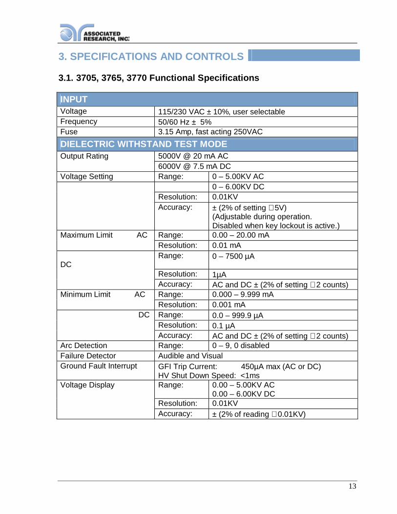
3. SPECIFICATIONS AND CONTROLS
3.1. 3705, 3765, 3770 Functional Specifications
INPUTVoltage 115/230 VAC ± 10%, user selectableFrequency 50/60 Hz ± 5%Fuse 3.15 Amp, fast acting 250VACDIELECTRIC WITHSTAND TEST MODEOutput Rating 5000V @ 20 mA AC
6000V @ 7.5 mA DCVoltage Setting Range: 0 – 5.00KV AC
0 – 6.00KV DCResolution: 0.01KVAccuracy: ± (2% of setting + 5V)
(Adjustable during operation.Disabled when key lockout is active.)
Maximum Limit AC Range: 0.00 – 20.00 mAResolution: 0.01 mA
DCRange: 0 – 7500 µA
Resolution: 1µAAccuracy: AC and DC ± (2% of setting + 2 counts)
Minimum Limit AC Range: 0.000 – 9.999 mAResolution: 0.001 mA
DC Range: 0.0 – 999.9 µAResolution: 0.1 µAAccuracy: AC and DC ± (2% of setting + 2 counts)
Arc Detection Range: 0 – 9, 0 disabledFailure Detector Audible and VisualGround Fault Interrupt GFI Trip Current: 450µA max (AC or DC)
HV Shut Down Speed: <1msVoltage Display Range: 0.00 – 5.00KV AC
0.00 – 6.00KV DCResolution: 0.01KVAccuracy: ± (2% of reading + 0.01KV)
14
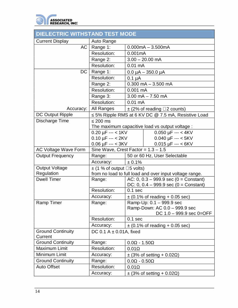
DIELECTRIC WITHSTAND TEST MODECurrent Display Auto Range
AC Range 1: 0.000mA – 3.500mAResolution: 0.001mARange 2: 3.00 – 20.00 mAResolution: 0.01 mA
DC Range 1: 0.0 µA – 350.0 µAResolution: 0.1 µARange 2: 0.300 mA – 3.500 mAResolution: 0.001 mARange 3: 3.00 mA – 7.50 mAResolution: 0.01 mA
Accuracy: All Ranges ± (2% of reading + 2 counts)DC Output Ripple ≤ 5% Ripple RMS at 6 KV DC @ 7.5 mA, Resistive LoadDischarge Time ≤ 200 ms
The maximum capacitive load vs output voltage :0.20 µF --- < 1KV0.10 µF --- < 2KV0.06 µF --- < 3KV
0.050 µF --- < 4KV0.040 µF --- < 5KV0.015 µF --- < 6KV
AC Voltage Wave Form Sine Wave, Crest Factor = 1.3 – 1.5Output Frequency Range: 50 or 60 Hz, User Selectable
Accuracy: ± 0.1%Output VoltageRegulation
± (1 % of output + 5 volts)from no load to full load and over input voltage range.
Dwell Timer Range: AC: 0, 0.3 – 999.9 sec (0 = Constant)DC: 0, 0.4 – 999.9 sec (0 = Constant)
Resolution: 0.1 secAccuracy: ± (0.1% of reading + 0.05 sec)
Ramp Timer Range: Ramp-Up: 0.1 – 999.9 secRamp-Down: AC 0.0 – 999.9 sec DC 1.0 – 999.9 sec 0=OFF
Resolution: 0.1 secAccuracy: ± (0.1% of reading + 0.05 sec)
Ground ContinuityCurrent
DC 0.1 A ± 0.01A, fixed
Ground Continuity Range: 0.0Ω - 1.50ΩMaximum Limit Resolution: 0.01ΩMinimum Limit Accuracy: ± (3% of setting + 0.02Ω)Ground Continuity Range: 0.0Ω - 0.50ΩAuto Offset Resolution: 0.01Ω
Accuracy: ± (3% of setting + 0.02Ω)

15
INSULATION RESISTANCE TEST MODEVoltage Setting Range: 30 – 1000V DC
Resolution: 1VAccuracy: ± (2% of setting + 5 volts)
Voltage Display Range: 0 – 1000 VResolution: 1VAccuracy: ± (2% of reading + 2 counts)
Resistance Display Range: 1 – 9999 MΩ (4 Digit, Auto Ranging)Resolution: 500VDC - 1000VDC
MΩ MΩ0.001 1.000 - 9.9990.01 10.00 - 99.990.1 100.0 - 999.91 1000 - 9999
Accuracy: ± (2% of reading + 2 counts) at testvoltage500 – 1000V and 1 – 999.9 MΩ
± (5% of reading + 2 counts) at testvoltage500 – 1000V and 1000 – 9999 MΩ
± (8% of reading + 2 counts) at testvoltage30 – 500V and 1 – 1000 MΩ
Maximum Limit Range: 0,1 – 9999 MΩ (0 = Off)Resolution 1MΩAccuracy Same as Resistance display
Minimum Limit Range: 1 – 9999 MΩResolution 1MΩAccuracy Same as Resistance display
Short Circuit Current Maximum: 9mA-peakRamp Timer Range:
Resolution:Accuracy:
Ramp-Up: 0.1 – 999.9 secRamp-Down: 1.0 – 999.9 sec 0=OFF0.1 sec± (0.1% of reading + 0.05 sec)
Delay Timer Range: 0, 0.5 – 999.9 sec (0 = Constant)Resolution: 0.1 secAccuracy: ± (0.1% of reading + 0.05 sec)
Ground Fault Interrupt GFI Trip Current: 450µA maxHV Shut Down Speed: <1ms
16
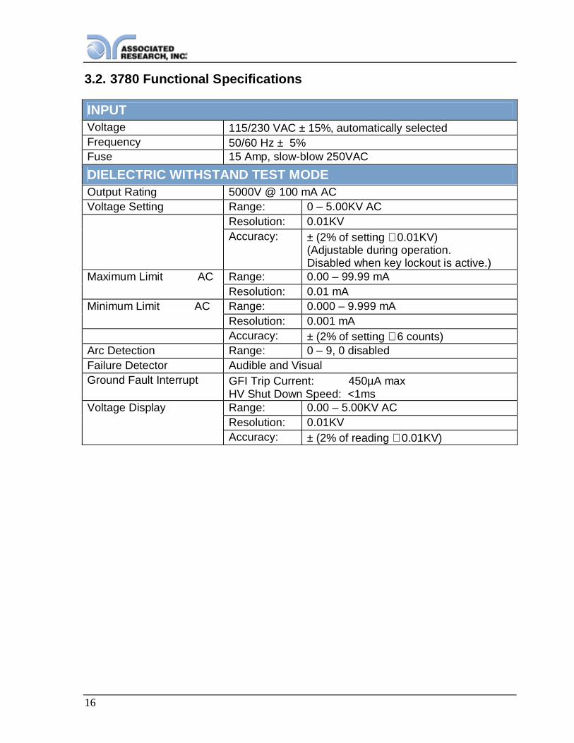
3.2. 3780 Functional Specifications
INPUTVoltage 115/230 VAC ± 15%, automatically selectedFrequency 50/60 Hz ± 5%Fuse 15 Amp, slow-blow 250VACDIELECTRIC WITHSTAND TEST MODEOutput Rating 5000V @ 100 mA ACVoltage Setting Range: 0 – 5.00KV AC
Resolution: 0.01KVAccuracy: ± (2% of setting + 0.01KV)
(Adjustable during operation.Disabled when key lockout is active.)
Maximum Limit AC Range: 0.00 – 99.99 mAResolution: 0.01 mA
Minimum Limit AC Range: 0.000 – 9.999 mAResolution: 0.001 mAAccuracy: ± (2% of setting + 6 counts)
Arc Detection Range: 0 – 9, 0 disabledFailure Detector Audible and VisualGround Fault Interrupt GFI Trip Current: 450µA max
HV Shut Down Speed: <1msVoltage Display Range: 0.00 – 5.00KV AC
Resolution: 0.01KVAccuracy: ± (2% of reading + 0.01KV)

17
DIELECTRIC WITHSTAND TEST MODECurrent Display Auto Range
AC Range 1: 0.000mA – 3.500mAResolution: 0.001mAAccuracy: ± (2% of setting + 2 counts)Range 2: 3.00 – 99.99 mAResolution: 0.01 mAAccuracy: ± (2% of setting + 6 counts)
AC Voltage Wave Form Sine Wave, Crest Factor = 1.3 – 1.5Output Frequency Range: 50 or 60 Hz, User Selectable
Accuracy: ± 0.1%Output VoltageRegulation
± (1 % of output + 5 volts)from no load to full load and over input voltage range.
Dwell Timer Range: 0, 0.3 – 999.9 sec (0 = Constant)Resolution: 0.1 secAccuracy: ± (0.1% of reading + 0.05 sec)
Ramp Timer Range: Ramp-Up: 0.1 – 999.9 secRamp-Down: AC 0.0 – 999.9 sec
Resolution: 0.1 secAccuracy: ± (0.1% of reading + 0.05 sec)
Ground ContinuityCurrent
DC 0.1 A ± 0.01A, fixed
Ground Continuity Range: 0.0Ω - 1.50ΩMaximum Limit Resolution: 0.01ΩMinimum Limit Accuracy: ± (3% of setting + 0.02Ω)Ground Continuity Range: 0.0Ω - 0.50ΩAuto Offset Resolution: 0.01Ω
Accuracy: ± (3% of setting + 0.02Ω)Output Short CircuitCurrent
> 200mA

18
GENERALRemote Input-OutputControl
The following input and output signals are providedthrough two 9 pin D-type connectors:1. Remote control: Test, Reset, and Remote
Interlock.2. Remote recall of memory program 1, 2 and 33. Outputs: Pass, Fail, Test-in-Process, and Reset
Program Memory 10 memories, 3 steps per memory, all steps within amemory are linkable.
Security Key Lock capability to avoid unauthorized access toall test parameters. Memory Lock capability to avoidunauthorized access to memory locations.
Ground Fault Interrupt Built-in Smart GFI circuitDisplay 128 x 64 dot resolution with front panel contrast
setting.Alarm Volume Setting Front panel adjustable volume setting with 10 set
points.Line Cord Detachable 7 ft. (2.13m) power cable terminated in a
three prong grounding plug.Terminations Detachable 5ft.(1.52m) high voltage and return leads
(2) with clips and a standard U.S. style (NEMA 5-15)remote receptacle box for testing items terminatedwith a line cord. International receptacles alsoavailable. Front and Rear outputs standard.
Mechanical Tilt up front feet.Dimensions: (W x H x D) (215 x 89 x 370 mm)(3705,3765,3770)Dimensions: (W x H x D) (430 x 133 x 350 mm)(3780)Weight: 20.96 lbs. (9.53Kgs) (3705,3765,3770)Weight: 49lbs. (22.23Kgs) (3780)
Environmental Operating Temperature : (0° - 40°C)Relative Humidity - 0 to 80%
Calibration Traceable to National Institute of Standards andTechnology (NIST). Calibration controlled bysoftware. Adjustments are made through front panelkeypad in a restricted access calibration mode.Calibration information stored in non-volatile memory.

19
3.3. Instrument Controls
3.3.1. Front Panel Controls
1. RESET BUTTON: Resets the instrument. If a failure condition occurs during atest, pressing this button will reset the system and shut off the alarm. Pressing thebutton a second time will clear the failure condition. The RESET button must bepressed before performing another test or changing any of the setup parameters.This button also serves as an abort signal to stop any test in progress.
2. TEST BUTTON: Starts a test.
3. GRAPHIC LCD: 128 X 64 Monographic LCD.
4. SOFT KEYS: Multifunction keys used to select screens and change parameters.
5. CONTINUITY OUTPUT TERMINAL: Connector used to attach the return testlead, adaptor box return lead, or test fixture return lead used during Continuitytesting.
6. RETURN OUTPUT TERMINAL: Connector used to attach the return test lead,adapter box return lead or test fixture return lead to the instrument. Thisconnection provides the return current path.
7. POWER SWITCH: Turns the Hipot tester ON or OFF.
8. HIGH VOLTAGE INDICATOR: This indicator flashes to warn the operator thathigh voltage is present at the high voltage output terminal.

20
9. HIGH VOLTAGE OUTPUT TERMINAL: Connector used to attach the highvoltage test lead, adapter box high voltage lead or test fixture high voltage lead tothe instrument. This connection provides the high voltage used during a Hipot test.

21
3.3.2. Rear Panel Controls
1. REAR PANEL OUTPUT TERMINALS: Second set of output connectors inparallel with the front panel connectors.
2. FUSE RECEPTACLE: To change the fuse, unplug the power (mains) cord andturn the fuse receptacle counter-clockwise. The fuse compartment will beexposed. Please replace the fuse with one of the proper rating (250 VAC, 15 A).
3. INPUT POWER RECEPTACLE: Standard IEC 320 connector for connection to astandard NEMA style line power (mains) cord.
4. INPUT POWER SWITCH: Sets the line voltage configuration of the instrument. Inthe left position it is set for 115 volt operation, in the right position it is set for 230volt operation.
5. CHASSIS GROUND (EARTH) CONNECTION: This terminal should be connectedto a good earth ground before operation.
6. BUS INTERFACE: Standard connector for interconnection to the RS-232 Businterface.
7. REMOTE SIGNAL OUTPUT: 9-Pin D-type subminiature female connector formonitoring PASS, FAIL, and PROCESSING output relay signals (See section 6.Connection of Remote I/O for more detailed information).
8. REMOTE SIGNAL INPUT: 9 pin D-type subminiature male connector for remotecontrol of TEST, RESET, and REMOTE INTERLOCK DISABLE functions, as wellas MEMORY SELECTION (See section 6. Connection of Remote I/O for moredetailed information).

22
9. CALIBRATION BUTTON: To put the instrument into the calibration mode pushthis button and turn on the power switch simultaneously.
23
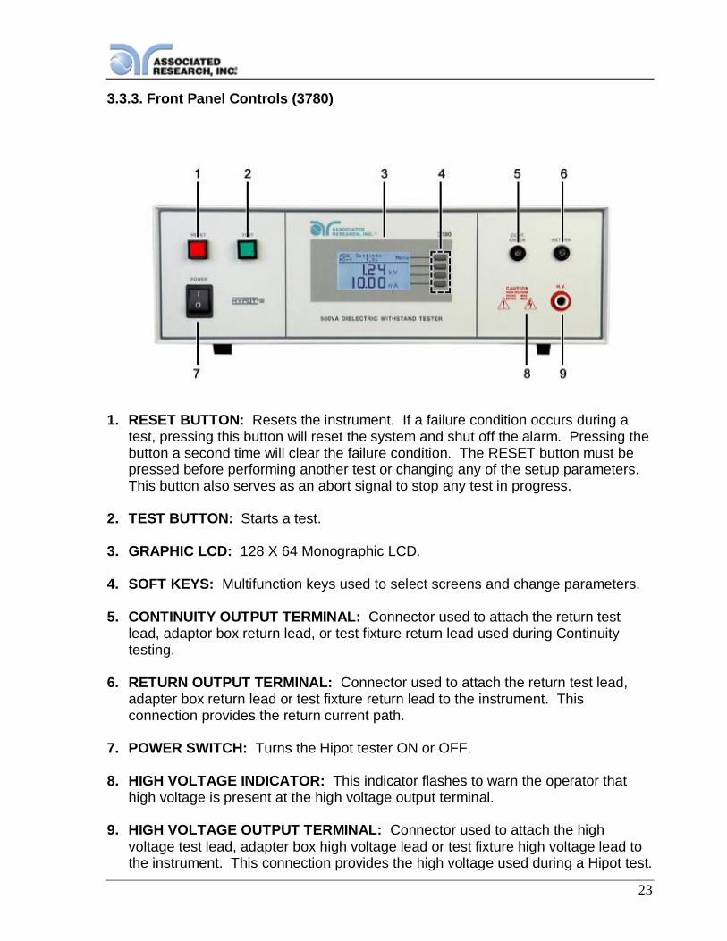
3.3.3. Front Panel Controls (3780)
1. RESET BUTTON: Resets the instrument. If a failure condition occurs during atest, pressing this button will reset the system and shut off the alarm. Pressing thebutton a second time will clear the failure condition. The RESET button must bepressed before performing another test or changing any of the setup parameters.This button also serves as an abort signal to stop any test in progress.
2. TEST BUTTON: Starts a test.
3. GRAPHIC LCD: 128 X 64 Monographic LCD.
4. SOFT KEYS: Multifunction keys used to select screens and change parameters.
5. CONTINUITY OUTPUT TERMINAL: Connector used to attach the return testlead, adaptor box return lead, or test fixture return lead used during Continuitytesting.
6. RETURN OUTPUT TERMINAL: Connector used to attach the return test lead,adapter box return lead or test fixture return lead to the instrument. Thisconnection provides the return current path.
7. POWER SWITCH: Turns the Hipot tester ON or OFF.
8. HIGH VOLTAGE INDICATOR: This indicator flashes to warn the operator thathigh voltage is present at the high voltage output terminal.
9. HIGH VOLTAGE OUTPUT TERMINAL: Connector used to attach the highvoltage test lead, adapter box high voltage lead or test fixture high voltage lead tothe instrument. This connection provides the high voltage used during a Hipot test.
24
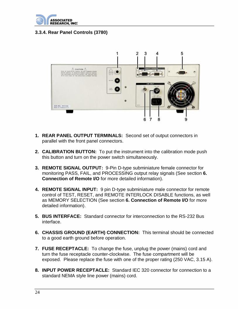
3.3.4. Rear Panel Controls (3780)
1. REAR PANEL OUTPUT TERMINALS: Second set of output connectors inparallel with the front panel connectors.
2. CALIBRATION BUTTON: To put the instrument into the calibration mode pushthis button and turn on the power switch simultaneously.
3. REMOTE SIGNAL OUTPUT: 9-Pin D-type subminiature female connector formonitoring PASS, FAIL, and PROCESSING output relay signals (See section 6.Connection of Remote I/O for more detailed information).
4. REMOTE SIGNAL INPUT: 9 pin D-type subminiature male connector for remotecontrol of TEST, RESET, and REMOTE INTERLOCK DISABLE functions, as wellas MEMORY SELECTION (See section 6. Connection of Remote I/O for moredetailed information).
5. BUS INTERFACE: Standard connector for interconnection to the RS-232 Businterface.
6. CHASSIS GROUND (EARTH) CONNECTION: This terminal should be connectedto a good earth ground before operation.
7. FUSE RECEPTACLE: To change the fuse, unplug the power (mains) cord andturn the fuse receptacle counter-clockwise. The fuse compartment will beexposed. Please replace the fuse with one of the proper rating (250 VAC, 3.15 A).
8. INPUT POWER RECEPTACLE: Standard IEC 320 connector for connection to astandard NEMA style line power (mains) cord.

25
9. THERMAL COOLING FAN: Full time cooling fan.
26
4. PROGRAMMING INSTRUCTIONS
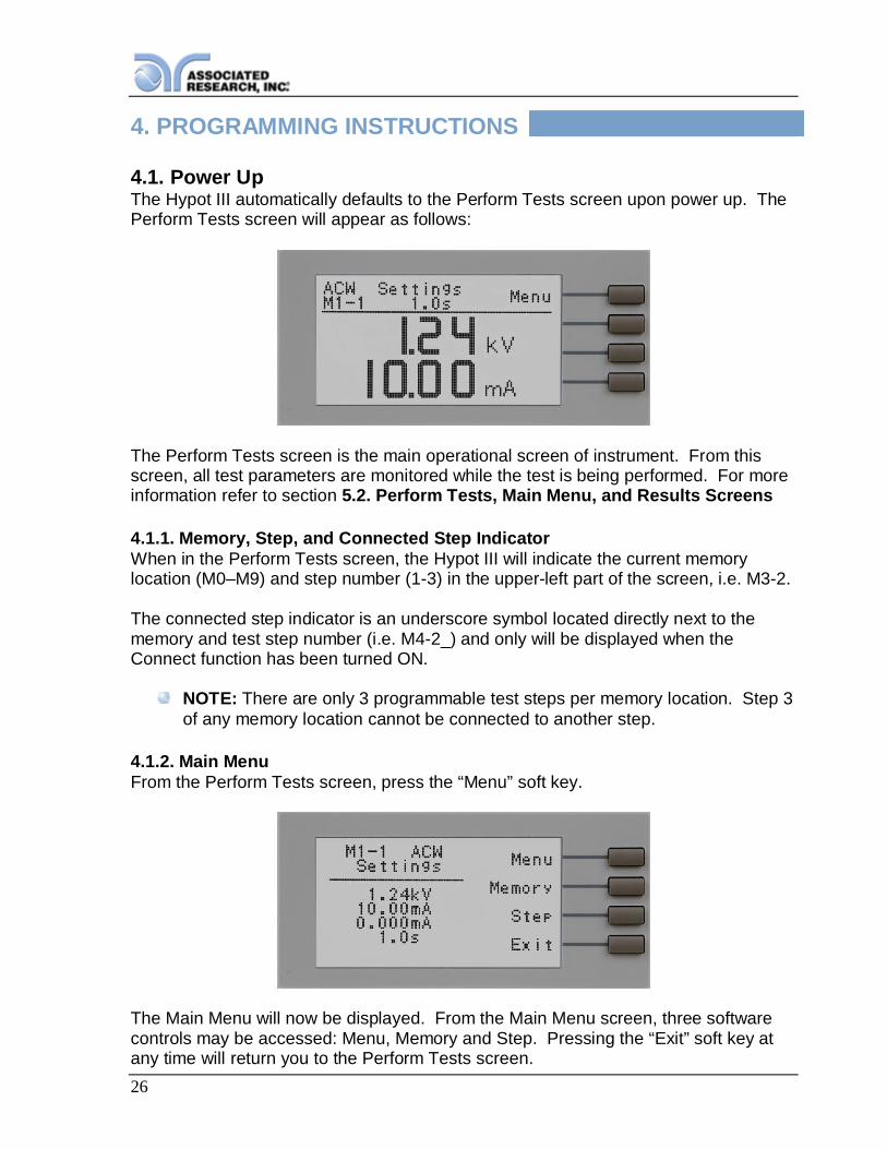
4.1. Power UpThe Hypot III automatically defaults to the Perform Tests screen upon power up. ThePerform Tests screen will appear as follows:
The Perform Tests screen is the main operational screen of instrument. From thisscreen, all test parameters are monitored while the test is being performed. For moreinformation refer to section 5.2. Perform Tests, Main Menu, and Results Screens
4.1.1. Memory, Step, and Connected Step IndicatorWhen in the Perform Tests screen, the Hypot III will indicate the current memorylocation (M0–M9) and step number (1-3) in the upper-left part of the screen, i.e. M3-2.
The connected step indicator is an underscore symbol located directly next to thememory and test step number (i.e. M4-2_) and only will be displayed when theConnect function has been turned ON.
NOTE: There are only 3 programmable test steps per memory location. Step 3of any memory location cannot be connected to another step.
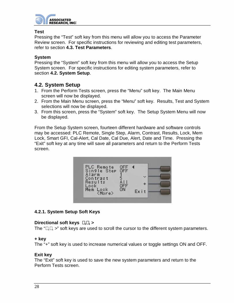
4.1.2. Main MenuFrom the Perform Tests screen, press the “Menu” soft key.
The Main Menu will now be displayed. From the Main Menu screen, three softwarecontrols may be accessed: Menu, Memory and Step. Pressing the “Exit” soft key atany time will return you to the Perform Tests screen.

27
MenuPressing the “Menu” soft key from the Main Menu will display the Results, Test andSystem selections. Please refer to section 5.2.3. Results, Test, and SystemSelections.
MemoryThe Hypot III has 10, 3-step programmable memory locations (M0-M9). Press the“Memory” soft key to increment the instrument to the desired memory location. As the“Memory” soft key is pressed, the parameters of the selected memory location areautomatically loaded into the instrument.
StepEach of the 10 memory locations in Hypot III has 3 programmable test steps that maybe connected together to create a multi-step test sequence. Press the “Step” soft keyto increment the test step number.
4.1.3. Results, Tests and System SelectionsFrom the Main Menu, press the “Menu” soft key.
From this screen, three software controls may be accessed: Results, Test andSystem. Pressing the “Exit” soft key at any time will return you to the Main Menuscreen.
ResultsPressing the “Results” soft key from this menu will allow you to review the test resultsof the last test performed. An example of a Results screen is shown below.
28
TestPressing the “Test” soft key from this menu will allow you to access the ParameterReview screen. For specific instructions for reviewing and editing test parameters,refer to section 4.3. Test Parameters.
SystemPressing the “System” soft key from this menu will allow you to access the SetupSystem screen. For specific instructions for editing system parameters, refer tosection 4.2. System Setup.
4.2. System Setup1. From the Perform Tests screen, press the “Menu” soft key. The Main Menu
screen will now be displayed.2. From the Main Menu screen, press the “Menu” soft key. Results, Test and System
selections will now be displayed.3. From this screen, press the “System” soft key. The Setup System Menu will now
be displayed.
From the Setup System screen, fourteen different hardware and software controlsmay be accessed: PLC Remote, Single Step, Alarm, Contrast, Results, Lock, MemLock, Smart GFI, Cal-Alert, Cal Date, Cal Due, Alert, Date and Time. Pressing the“Exit” soft key at any time will save all parameters and return to the Perform Testsscreen.
4.2.1. System Setup Soft Keys
Directional soft keys ∧,∨, >The “∧,∨, >” soft keys are used to scroll the cursor to the different system parameters.
+ keyThe “+” soft key is used to increase numerical values or toggle settings ON and OFF.
Exit keyThe “Exit” soft key is used to save the new system parameters and return to thePerform Tests screen.

29
You can control yourAssociated Research, Inc.instrument using basic PLCinputs and outputs. Executetests and read PASS/FAILconditions remotely, selectmemory locations, or set upa safe work station by usingan interlocked enclosure.
DID YOU KNOW?
4.2.2. System ParametersUse the directional soft keys, “∨,∧,>”, to navigate the system parameters duringreviewing and editing. The directional softkeys will change depending on whichparameter the cursor is pointing to.
PLC RemoteWhen the PLC remote is turned ON the frontpanel TEST button is disabled and a testmay only be started through the rear panelI/O. If you attempt to start a test from theTEST button on the front panel when thePLC Remote function is turned ON, a pop-up message will be displayed. The pop-upmessage will appear as follows:
Refer to the section 6. Connection of Remote I/O for more details.
Single StepThis function is used to temporarily override the automatic connection feature. Whenthe Single Step function is ON the instrument will pause after each test step iscompleted. To continue the test sequence, press the TEST button to execute the nextconnected test step. Each time the TEST button is pressed the next connected teststep will execute. If you press the RESET button before completing all connected teststeps, it will return you to the original starting test step. If a step fails and you wish tocontinue to the next test step press TEST.
Alarm VolumeThe numbers 0 through 9 correspond to different volume settings, 0 meaning thevolume is OFF and 9 meaning the volume is at the loudest setting. After the “+” softkey is pressed a momentary alarm chirp will occur to indicate the volume of the newsetting.
LCD ContrastThe numbers 0 through 9 correspond to the different contrast settings, 0 meaning thelightest color of displayed characters and 9 meaning the darkest color of displayedcharacters. After the “+” soft key is pressed the display will automatically adjust to thenew display setting.
30
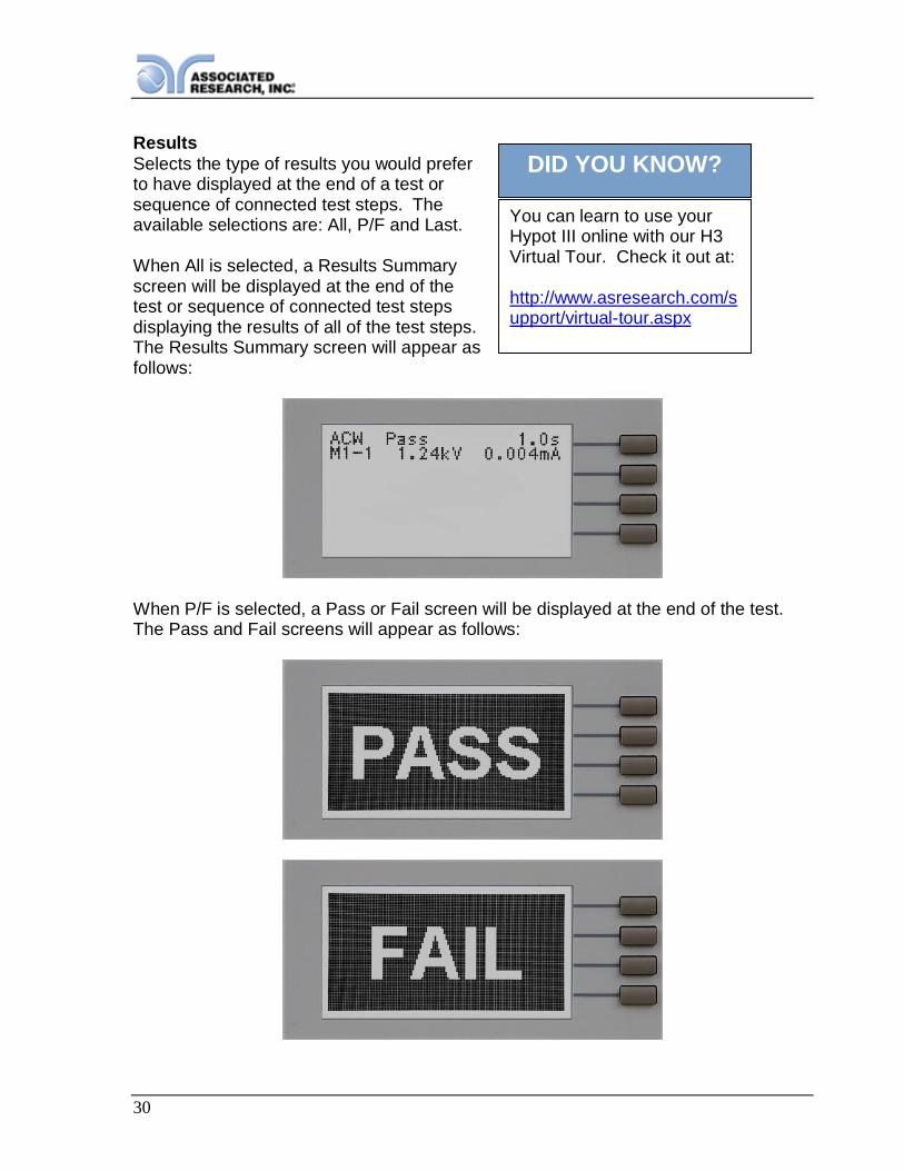
DID YOU KNOW?ResultsSelects the type of results you would preferto have displayed at the end of a test orsequence of connected test steps. Theavailable selections are: All, P/F and Last.
When All is selected, a Results Summaryscreen will be displayed at the end of thetest or sequence of connected test stepsdisplaying the results of all of the test steps.The Results Summary screen will appear asfollows:
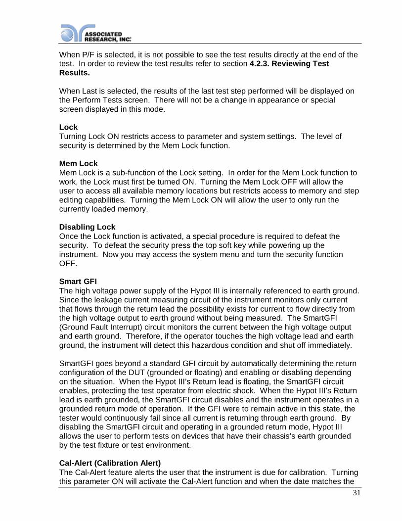
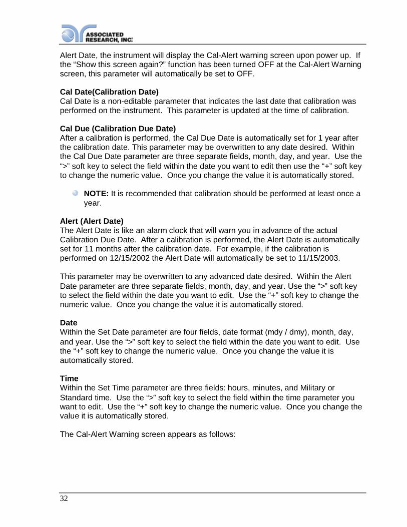
When P/F is selected, a Pass or Fail screen will be displayed at the end of the test.The Pass and Fail screens will appear as follows:
You can learn to use yourHypot III online with our H3Virtual Tour. Check it out at:
http://www.asresearch.com/support/virtual-tour.aspx
31
When P/F is selected, it is not possible to see the test results directly at the end of thetest. In order to review the test results refer to section 4.2.3. Reviewing TestResults.
When Last is selected, the results of the last test step performed will be displayed onthe Perform Tests screen. There will not be a change in appearance or specialscreen displayed in this mode.
LockTurning Lock ON restricts access to parameter and system settings. The level ofsecurity is determined by the Mem Lock function.
Mem LockMem Lock is a sub-function of the Lock setting. In order for the Mem Lock function towork, the Lock must first be turned ON. Turning the Mem Lock OFF will allow theuser to access all available memory locations but restricts access to memory and stepediting capabilities. Turning the Mem Lock ON will allow the user to only run thecurrently loaded memory.
Disabling LockOnce the Lock function is activated, a special procedure is required to defeat thesecurity. To defeat the security press the top soft key while powering up theinstrument. Now you may access the system menu and turn the security functionOFF.
Smart GFIThe high voltage power supply of the Hypot III is internally referenced to earth ground.Since the leakage current measuring circuit of the instrument monitors only currentthat flows through the return lead the possibility exists for current to flow directly fromthe high voltage output to earth ground without being measured. The SmartGFI(Ground Fault Interrupt) circuit monitors the current between the high voltage outputand earth ground. Therefore, if the operator touches the high voltage lead and earthground, the instrument will detect this hazardous condition and shut off immediately.
SmartGFI goes beyond a standard GFI circuit by automatically determining the returnconfiguration of the DUT (grounded or floating) and enabling or disabling dependingon the situation. When the Hypot III’s Return lead is floating, the SmartGFI circuitenables, protecting the test operator from electric shock. When the Hypot III’s Returnlead is earth grounded, the SmartGFI circuit disables and the instrument operates in agrounded return mode of operation. If the GFI were to remain active in this state, thetester would continuously fail since all current is returning through earth ground. Bydisabling the SmartGFI circuit and operating in a grounded return mode, Hypot IIIallows the user to perform tests on devices that have their chassis’s earth groundedby the test fixture or test environment.
Cal-Alert (Calibration Alert)The Cal-Alert feature alerts the user that the instrument is due for calibration. Turningthis parameter ON will activate the Cal-Alert function and when the date matches the
32
Alert Date, the instrument will display the Cal-Alert warning screen upon power up. Ifthe “Show this screen again?” function has been turned OFF at the Cal-Alert Warningscreen, this parameter will automatically be set to OFF.
Cal Date(Calibration Date)Cal Date is a non-editable parameter that indicates the last date that calibration wasperformed on the instrument. This parameter is updated at the time of calibration.
Cal Due (Calibration Due Date)After a calibration is performed, the Cal Due Date is automatically set for 1 year afterthe calibration date. This parameter may be overwritten to any date desired. Withinthe Cal Due Date parameter are three separate fields, month, day, and year. Use the“>” soft key to select the field within the date you want to edit then use the “+” soft keyto change the numeric value. Once you change the value it is automatically stored.
NOTE: It is recommended that calibration should be performed at least once ayear.
Alert (Alert Date)The Alert Date is like an alarm clock that will warn you in advance of the actualCalibration Due Date. After a calibration is performed, the Alert Date is automaticallyset for 11 months after the calibration date. For example, if the calibration isperformed on 12/15/2002 the Alert Date will automatically be set to 11/15/2003.
This parameter may be overwritten to any advanced date desired. Within the AlertDate parameter are three separate fields, month, day, and year. Use the “>” soft keyto select the field within the date you want to edit. Use the “+” soft key to change thenumeric value. Once you change the value it is automatically stored.
DateWithin the Set Date parameter are four fields, date format (mdy / dmy), month, day,and year. Use the “>” soft key to select the field within the date you want to edit. Usethe “+” soft key to change the numeric value. Once you change the value it isautomatically stored.
TimeWithin the Set Time parameter are three fields: hours, minutes, and Military orStandard time. Use the “>” soft key to select the field within the time parameter youwant to edit. Use the “+” soft key to change the numeric value. Once you change thevalue it is automatically stored.
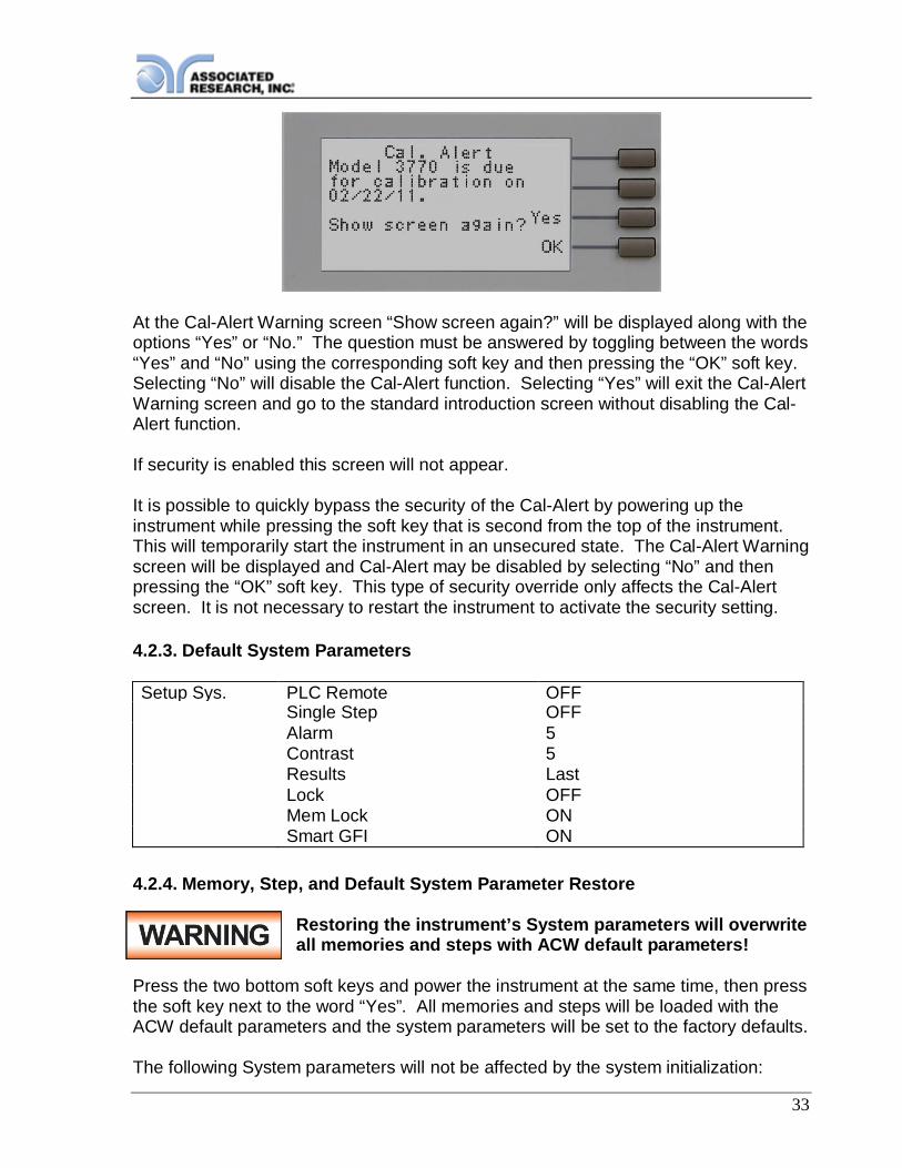
The Cal-Alert Warning screen appears as follows:
33
At the Cal-Alert Warning screen “Show screen again?” will be displayed along with theoptions “Yes” or “No.” The question must be answered by toggling between the words“Yes” and “No” using the corresponding soft key and then pressing the “OK” soft key.Selecting “No” will disable the Cal-Alert function. Selecting “Yes” will exit the Cal-AlertWarning screen and go to the standard introduction screen without disabling the Cal-Alert function.
If security is enabled this screen will not appear.
It is possible to quickly bypass the security of the Cal-Alert by powering up theinstrument while pressing the soft key that is second from the top of the instrument.This will temporarily start the instrument in an unsecured state. The Cal-Alert Warningscreen will be displayed and Cal-Alert may be disabled by selecting “No” and thenpressing the “OK” soft key. This type of security override only affects the Cal-Alertscreen. It is not necessary to restart the instrument to activate the security setting.
4.2.3. Default System Parameters
Setup Sys. PLC Remote OFFSingle Step OFFAlarm 5Contrast 5Results LastLock OFFMem Lock ONSmart GFI ON
4.2.4. Memory, Step, and Default System Parameter Restore
Restoring the instrument’s System parameters will overwriteall memories and steps with ACW default parameters!
Press the two bottom soft keys and power the instrument at the same time, then pressthe soft key next to the word “Yes”. All memories and steps will be loaded with theACW default parameters and the system parameters will be set to the factory defaults.
The following System parameters will not be affected by the system initialization:
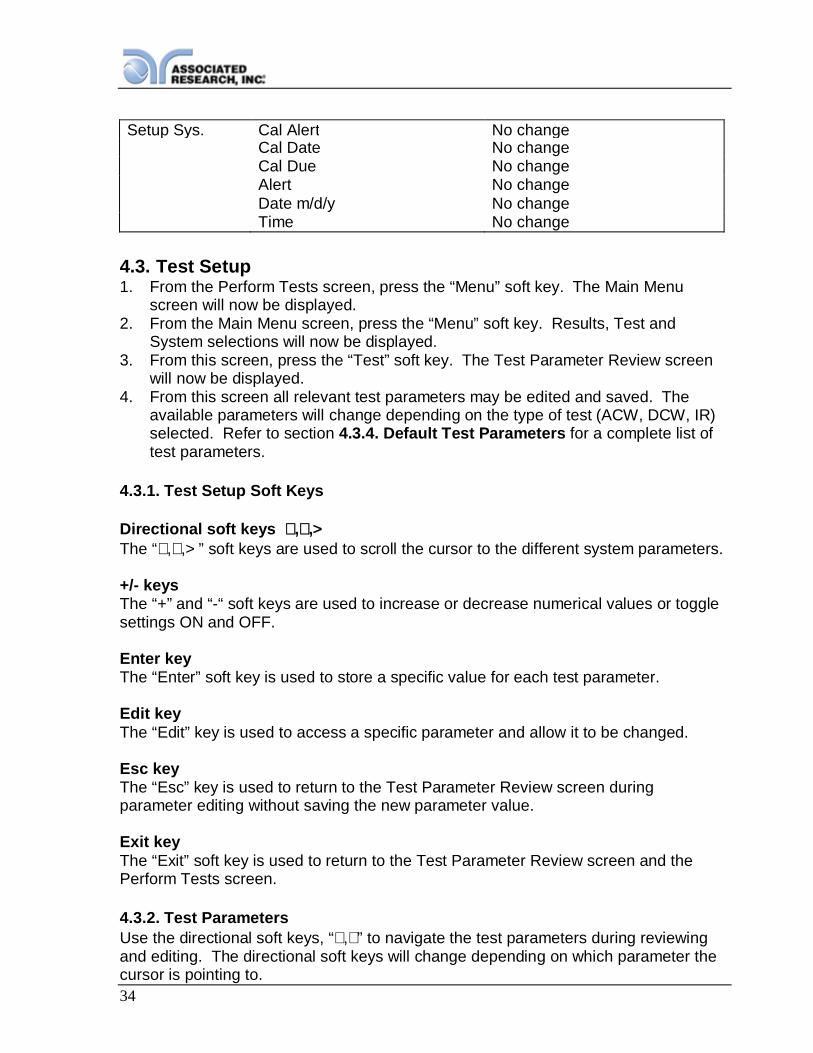
34
Setup Sys. Cal Alert No changeCal Date No changeCal Due No changeAlert No changeDate m/d/y No changeTime No change
4.3. Test Setup1. From the Perform Tests screen, press the “Menu” soft key. The Main Menu
screen will now be displayed.2. From the Main Menu screen, press the “Menu” soft key. Results, Test and
System selections will now be displayed.3. From this screen, press the “Test” soft key. The Test Parameter Review screen
will now be displayed.4. From this screen all relevant test parameters may be edited and saved. The
available parameters will change depending on the type of test (ACW, DCW, IR)selected. Refer to section 4.3.4. Default Test Parameters for a complete list oftest parameters.
4.3.1. Test Setup Soft Keys
Directional soft keys ∧,∨,>The “∧,∨,> ” soft keys are used to scroll the cursor to the different system parameters.
+/- keysThe “+” and “-“ soft keys are used to increase or decrease numerical values or togglesettings ON and OFF.
Enter keyThe “Enter” soft key is used to store a specific value for each test parameter.
Edit keyThe “Edit” key is used to access a specific parameter and allow it to be changed.
Esc keyThe “Esc” key is used to return to the Test Parameter Review screen duringparameter editing without saving the new parameter value.
Exit keyThe “Exit” soft key is used to return to the Test Parameter Review screen and thePerform Tests screen.
4.3.2. Test ParametersUse the directional soft keys, “∨,∧” to navigate the test parameters during reviewingand editing. The directional soft keys will change depending on which parameter thecursor is pointing to.

35
DID YOU KNOW?
Voltage: The voltage that is applied to the High Voltage and Return Terminals duringa test.
Max Lmt: The maximum current or resistance threshold that triggers a failure whenexceeded.
Min Lmt: The minimum current or resistance threshold that triggers a failure when notexceeded.
Ramp Up: The length of time that is allowed for the test voltage to climb from 0 to theprogrammed test voltage.
Dwell: The length of time that is allowed for the programmed test voltage to beapplied.
Delay: The length of time that the programmed test voltage is applied but no judgmentof the set parameters is made. Judgment of the parameters is not made until the endof the delay time.
Ramp Dn: The length of time that is allowed for the testvoltage to decay from programmed test voltage to 0.
Arc Sense: The maximum allowable threshold forarcing. The numbers 0 through 9 correspond to thedifferent arc sensitivity levels, 1 being the mostsensitive, 9 being the least sensitive, and 0 being OFF.After the “+” or “-” soft keys are pressed, the arcsensitivity will automatically adjust to the new setting.Arc detection is not required for testing, but may beused as a diagnostic tool. Contact AssociatedResearch, Inc. or visit our website for more information.
Frequency: This parameter is available in AC testingonly and may be toggled between 50 and 60 Hz.
Continuity: This function checks for a connection between the Cont. Check andReturn Terminals. This is a basic DC continuity check that measures the continuityvalue but does not display it. Continuity may be turned ON or OFF.
Offset: Used during the Continuity test to factor out test lead and fixturing resistance.
Connect: This function will connect or link the current test step to the next test step.The third test step in a memory will not have this function because it is the last teststep of the memory location.
Associated Research, Incprovides detailedwhitepapers and articleson our website. Checkout the following link formore information on ArcSensitivity:http://www.asresearch.com/events-training/articles.aspx
36
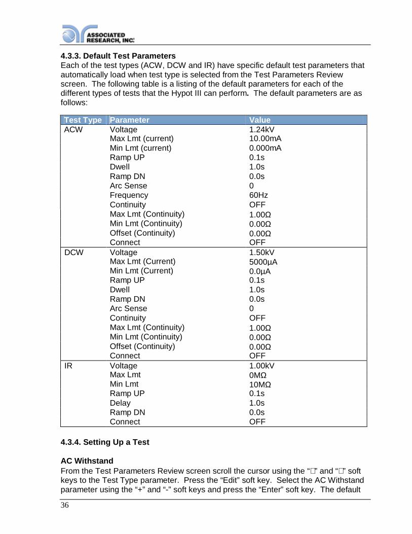
4.3.3. Default Test ParametersEach of the test types (ACW, DCW and IR) have specific default test parameters thatautomatically load when test type is selected from the Test Parameters Reviewscreen. The following table is a listing of the default parameters for each of thedifferent types of tests that the Hypot III can perform. The default parameters are asfollows:
Test Type Parameter ValueACW Voltage 1.24kV
Max Lmt (current) 10.00mAMin Lmt (current) 0.000mARamp UP 0.1sDwell 1.0sRamp DN 0.0sArc Sense 0Frequency 60HzContinuity OFFMax Lmt (Continuity) 1.00ΩMin Lmt (Continuity) 0.00ΩOffset (Continuity) 0.00ΩConnect OFF
DCW Voltage 1.50kVMax Lmt (Current) 5000µAMin Lmt (Current) 0.0µARamp UP 0.1sDwell 1.0sRamp DN 0.0sArc Sense 0Continuity OFFMax Lmt (Continuity) 1.00ΩMin Lmt (Continuity) 0.00ΩOffset (Continuity) 0.00ΩConnect OFF
IR Voltage 1.00kVMax Lmt 0MΩMin Lmt 10MΩRamp UP 0.1sDelay 1.0sRamp DN 0.0sConnect OFF
4.3.4. Setting Up a Test
AC WithstandFrom the Test Parameters Review screen scroll the cursor using the “∧” and “∨” softkeys to the Test Type parameter. Press the “Edit” soft key. Select the AC Withstandparameter using the “+” and “-” soft keys and press the “Enter” soft key. The default

37
AC Withstand parameters will now be loaded into the currently selected memory andstep. Press the “Enter” soft key to accept the parameters or press the “Esc” soft keyreturn to exit without saving.
From the AC Withstand Parameter Review screens the following parameters may beselected for editing: Voltage, Max-Limit, Min-Limit, Ramp Up, Dwell Time, RampDown, Arc Sense, Frequency, Arc Detect (ON/OFF), Continuity selection (ON/OFF),Continuity Max-Limit, Continuity Min-Limit, and Continuity Offset.
DC Withstand (Models 3765 and 3770)From the Test Parameter Review screen scroll the cursor using “∧” and “∨” soft keysto the Test Type parameter. Press the “Edit” soft key. Select the DC Withstandparameter using the “+” and “-” soft keys and press the “Enter” soft key. The defaultDC Withstand parameters will now be loaded into the currently selected memory andstep. Press the “Enter” soft key to accept the parameters or press the “Esc” soft keyto exit without saving.
From the DC Withstand Setting screen the following parameters may be controlled:Voltage, Max-Limit, Min-Limit, Ramp Up, Dwell Time, Ramp Down, Arc Sense, ArcDetect (ON/OFF), and Continuity (ON/OFF).
OffsetWhen the Continuity feature is turned ON, the Offset function may be used tocompensate for lead and test fixture resistance during the Continuity test. Using the“∧” and “∨” soft keys scroll the cursor to the Offset parameter and press the “Edit” softkey. You may now manually or automatically set an Offset value.
38
To manually set the Offset use the “+” and “-” soft keys to increase and decrease theresistance value. Press the “Enter” soft key to accept the new value or press the“Esc” soft key to return to the previous screen without saving.
To automatically set an Offset value, set the output voltage, current, and frequency tothe values that will be used on the DUT and connect the test cables and all testfixturing to the instrument. Next, connect the ends of the test cables together andpress the TEST button. The instrument will now read the lead resistance and updateOffset parameter automatically. Press the “Enter” soft key to accept the new value orpress the “Esc” soft key to exit without saving.
NOTE: do not connect the DUT to the instrument when performing an offset.This will create erroneous results when a test is performed.
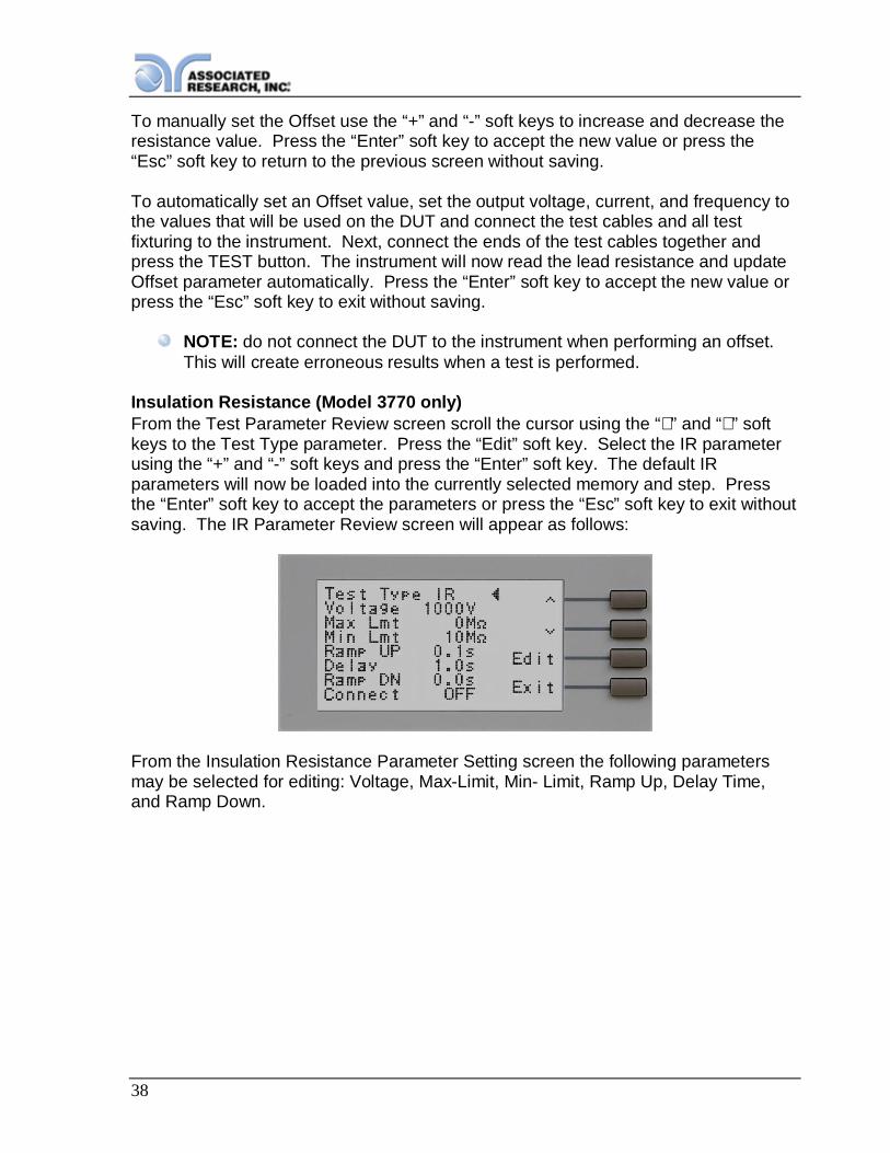
Insulation Resistance (Model 3770 only)From the Test Parameter Review screen scroll the cursor using the “∧” and “∨” softkeys to the Test Type parameter. Press the “Edit” soft key. Select the IR parameterusing the “+” and “-” soft keys and press the “Enter” soft key. The default IRparameters will now be loaded into the currently selected memory and step. Pressthe “Enter” soft key to accept the parameters or press the “Esc” soft key to exit withoutsaving. The IR Parameter Review screen will appear as follows:
From the Insulation Resistance Parameter Setting screen the following parametersmay be selected for editing: Voltage, Max-Limit, Min- Limit, Ramp Up, Delay Time,and Ramp Down.

39
5. OPERATING INSTRUCTIONS
5.1. Instrument ConnectionsThe test leads and the adaptor box may be connected to the jacks located on the frontor back of Hypot III. These receptacles are wired in parallel and either set can beused depending on the specific application.
5.1.1. Connecting the Test LeadsThe instrument comes with all cables necessary for performing a Hipot, IR orContinuity test. Plug the red alligator clip into the High Voltage Terminal on the HypotIII. Connect one of two black alligator clip leads to the Return Terminal and the otherto the Cont. Check Terminal.
5.1.2. Connecting the Adapter BoxThe adapter box provides an easy way to connect a line cord-terminated DUT to theHypot III. The following diagram shows how to connect the adapter box to the HypotIII and to the DUT.

40
5.1.3. Interlock ConnectorHypot III is equipped with a Remote Interlock feature. Remote Interlock utilizes a setof closed contacts to enable the instrument’s output. If the Remote Interlock contactsare open the output of the instrument will be disabled. To disable the RemoteInterlock feature connect the Interlock Key into the Signal Input port located on theback of the tester.
5.2. Performing a Test1. From the Main Menu, select the memory and step you wish to perform then press
the “Exit” soft key to return to the Perform Tests screen.2. Attach the appropriate load or DUT to the instrument. Refer to section 5.1.
Instrument Connections for instrument connections.3. Press the TEST button.4. The instrument will now perform the test or sequence of connected tests.
NOTE: If the test is started from a step other than 01, it will alwaysreturn to the originally selected step when you push RESET or TESTbuttons.
Manual Voltage AdjustmentWhen Hypot III is performing a test, “+” and “-” soft key selections will appear. Thesesoft keys may be used to adjust the output voltage while performing a test.

41
Pressing the “+” soft key will increase the output voltage and pressing the “-” soft keywill decrease the output voltage. Manual voltage adjustment temporarily overrides thevoltage setting and only remains in effect until the test is terminated by Pass, Fail, orAbort conditions.
When the Lock parameter is ON in the System Menu, manual voltage adjustment isdisabled. You will not see the “+” and “-” soft key selections in this case.
5.3. Test MeteringEach test performed by the Hypot III contains a unique set of parameters andtherefore requires specialized metering for each test. The following table describesthe meters displayed for each of the different tests.
TEST TYPE CURRENT VOLTAGE TIME RESISTANCEAC
Withstand X X X -
DCWithstand X X X -
IR - X X X
5.4. Results ScreensThe Hypot III may be configured to display one of three different types of Resultsscreens (see section 4.2. Setup System for more information). To access the resultsscreen use one of the following methods:
Method 1, Hot keyPressing the bottom soft key at the Perform Tests screen will display the Resultsscreen.
Method 2, Menu Selection1. From the Perform Tests screen, press the “Menu” soft key. The Main Menu will
now be displayed.2. From the Main Menu screen, press the “Menu” soft key. The Results, Test and
System selections will now be displayed.3. From this screen, press the “Result” soft key. The Results screen will now be
displayed. The Results screen will appear as follows:

42
NOTE: For multi-step tests, use the “∧” and “∨” soft keys to scroll through theresults.
5.5. Error MessagesWhile performing tests a number of messages will be displayed to indicate the teststate or test results. These messages are displayed in the status area of the screenlocated on the first line at the top of the LCD. These messages are also used on otherscreens where test results are displayed.
Abort: This message appears on the display if the test in process is aborted with theRESET button or remote RESET control.
Max-Fail: This message appears on the display if the measured reading exceeds theMax Lmt current setting of the AC/DC Withstand test or Max Lmt resistance setting ofthe Insulation Resistance test.
Min-Fail: This message appears on the display if the measured reading drops belowthe Min Lmt current setting of the AC/DC Withstand test or Min Lmt resistance settingof the Insulation Resistance test.
Cont. Max: This message appears on the display during the AC/DC Withstand test ifthe measured reading exceeds the Max Lmt continuity resistance setting (Continuityfunction must be turned ON).
Cont. Min: This message appears on the display during the AC/DC Withstand test ifthe measured reading drops below the Min Lmt continuity resistance setting(Continuity function must be turned ON).
43
Arc-Fail: This message appears on the display if the DUT arcing current exceeds theArc Sense limit and Arc function is active (Arc Sense = 1… 9) during the AC/DCWithstand test.
Short: This message appears on the display if the instrument detects a short circuitcondition
Breakdown: This message appears on the display if the DUT current is well beyondthe metering range of the test and the arcing condition is beyond the arc sense limit.
GND-Fault: This message appears on the display if the GFI threshold is exceededduring the test.
Interlock Open: This message appears on the display if the Remote Interlock featureis activated before or during a test. See section 6.2. Remote Signal Inputs andMemory Access for more information.
Out-Error: This message appears on the display if the instrument has an internalproblem and the TEST button is pressed. The RESET button is not active while thisscreen is displayed. To clear this screen and return to test mode press the “Exit” softkey. When the “Exit” soft key is pressed the instrument will continue with its normalfailure indication process. The failure light and Alarm can then be cleared by pressingthe RESET button.
NOTE: If the instrument continues to power up in this condition it should besent in for service or repair.

44
6. CONNECTION OF REMOTE I/OTwo 9 pin D-type connectors mounted on the rear panel provide REMOTE-INPUT-OUTPUT control and information. These connectors mate with astandard 9 pin D-type subminiature connector provided by the user. The outputmates to a male (plug) connector while the input mates to a female (receptacle)connector. For best performance, a shielded cable should be used. To avoidground loops the shield should not be grounded at both ends of the cable.Suggested AMP part numbers for interconnecting to the Remote I/O are shownbelow:
205204-4 PLUG SHELL WITH GROUND INDENTS205203-3 RECEPTACLE SHELL745254-7 CRIMP SNAP-IN PIN CONTACT (for plug)745253-7 CRIMP SNAP-IN SOCKET CONTACT (for receptacle)745171-1 SHIELDED CABLE CLAMP (for either plug or receptacle)747784-3 JACKSCREW SET (2)
6.1. Remote Signal OutputsThe rear panel connector provides three output signals to remotely monitorPASS, FAIL, and PROCESSING conditions. The monitoring signals areprovided by three normally open internal relays that toggle ON and OFF toindicate the condition of the tester. These are normally open free contacts andwill not provide any voltage or current. The ratings of the contacts are 1 AAC /
45
The Remote Signal Inputconnector may be used withvarious accessories,including light curtains, footswitches, and safety probes.Contact AssociatedResearch, Inc. for moreinformation.
DID YOU KNOW?
125 VAC (0.5 ADC / 30 VDC). The signal outputs are provided on the 9 pinfemale D-type connector. Below is a list that indicates what conditions activateeach pin. When a terminal becomes active the relay closes thereby allowing theexternal voltage to operate an external device.
Pins 1 and 2 provide the PASS signal.Pins 3 and 4 provide the FAIL signal.Pins 5 and 6 provide the PROCESSING signal.Pins 7 and 8 provide the RESET OUT signal.
The following describes how the relays operate for each test condition:
PROCESSING – The relay contact closes the connection between pin (5) andpin (6) while the instrument is performing a test. The connection is opened at theend of the test.
PASS – The relay contact closes the connection between pin (1) and pin (2) afterdetecting that the item under test passed all tests. The connection is openedwhen the next test is initiated or the reset function is activated.
FAIL – The relay contact closes the connection between pin (3) and pin (4) afterdetecting that the item under test failed. The connection will open when the nexttest is initiated or the reset function activated.
RESET OUT – The relay contact closes the connection between pin (7) and pin(8) while the reset function is activated. This is only a continuous closuredependent on the length of time the reset button is held in an active state.
6.2. Remote Signal Inputs and Memory AccessThe Hypot III remote connector enables remote operation of the TEST, RESET,and REMOTE INTERLOCK functions, and allows the operator to select MemoryLocation 1, 2, and 3.
When the PLC Remote mode is on, the Hypot III will respond to simple switch orrelay contacts closures. A normally open momentary switch can be wired acrosspins 3 and 5 to allow remote operation of theTEST function. A minimum pulse width orcontact closure of 20mS is required to guaranteea test start. A normally open momentary switchcan be wired across pins 2 and 5 to allow remoteoperation of the RESET function. A minimumpulse width or contact closure of 50mS isrequired to guarantee that a running test willabort. When the PLC remote function is (ON) theTEST switch on the front panel will be disabled toprevent a test from being activated through thisswitch. For safety, the front panel RESET switch
46
remains active even when a remote reset switch is connected so that highvoltage can be shut down from either location.
The Remote File Select function gives the user the capability to quickly changeparameters and initiate a test remotely. Three internal memory programs can beaccessed by connecting terminals 7, 8, and 9 in different combinations. Thememory select bits should be set simultaneously and remain set for a minimumof 1ms to guarantee that the correct memory will be selected.
ACTIVATING MEMORY PROGRAM FUNCTIONSTHROUGH THE REMOTE CONNECTOR, SELECTS THEPROGRAM AND STARTS THE TEST WHICH IS
PREPROGRAMMED INTO THAT MEMORY
DO NOT CONNECT VOLTAGE OR CURRENT TO THESIGNAL INPUTS, THIS COULD RESULT IN DAMAGE TOTHE CONTROL CIRCUITRY.
Memory Location 1 – Momentarily connecting terminal 7 to 8 signals theinstrument to immediately begin the test program that is stored in MemoryLocation 1.
Memory Location 2 – Momentarily connecting terminal 7 to 9 signals theinstrument to immediately begin the test program that is stored in MemoryLocation 2.
Memory Location 3 – Momentarily connecting terminal 7 to terminals 8 and 9signals the instrument to immediately begin the test program that is stored inMemory Location 3.
Remote InterlockHypot III is equipped with a Remote Interlock feature. Remote Interlock utilizes aset of closed contacts to enable the instrument’s output. If the Remote Interlockcontacts are open the output of the instrument will be disabled. Remote Interlockcould also be referred to as a remote system lockout, utilizing “fail when open”logic. If the Remote Interlock contacts are open and the TEST button is pushed,a pop-up message will be displayed on the screen for two seconds. Themessage will appear as follows:

47
If the Remote Interlock contacts are opened during a test, the pop-up messagewill be displayed and the test will abort. The hardware and has been configuredto provide the interlock connections on pins 4 and 5 of the Remote Interface,Signal Input port. The instrument can still be used without the external interlockdevice as long as the Interlock Disable Key (38075 provided with unit) is pluggedinto the Remote Interface, Signal Input port. If there is nothing connected to theRemote Interface, Signal Input port to provide a connection to the RemoteInterlock, the instrument will not perform tests.

48
7. BUS REMOTE INTERFACEThis section provides information on the proper use and configuration of bus remoteinterface. The RS-232 remote interface is standard on all 3700 series models.
7.1. RS-232 InterfaceThis interface is standard on Hypot III. This interface provides all of the controlcommands and parameter setting commands. All commands can be found in thecommand list, section 7.2.1 to 7.2.5 of this manual.
7.1.1. RS-232 ConnectorThe RS-232 cabling should be configured as follows for a 9-pin serial port interface:
7.1.2. Communications Port ConfigurationThe COM port should have the following configuration:
19200 baud 8 data bits 1 stop bit No parity
This interface does not support XON/XOFF protocol or any hardware handshaking.The controller should be configured to ignore the handshaking lines DTR (pin 4), DSR(pin 6) CTS (pin 8) and RTS (pin 7). If the port cannot be configured through softwareto ignore these lines the handshake lines should be jumpered together in two differentsets. Pins 4 and 6 should be jumpered together and pins 7 and 8 should be jumperedtogether at the controller end of the cable.
7.1.3. Sending and Receiving Commands
Sending DataOnce a command is sent to the instrument over the RS-232 bus the instrument willsend one of two responses. If the transfer was recognized and completed theinstrument will return with 06 hex or 6 decimal, the Acknowledge (ACK) ASCII controlcode. If there is an error with the command string that is sent, the instrument willrespond with 15 hex or 21 decimal, the Not Acknowledge (NAK) ASCII control code.The ACK or NAK response allows for software handshaking to monitor and controldata flow.
Instrument RS-232 Port PC / Bus Controller
2
3
5
2
3
5
TD
RD
TD
RD
SIGGND
SIGGND
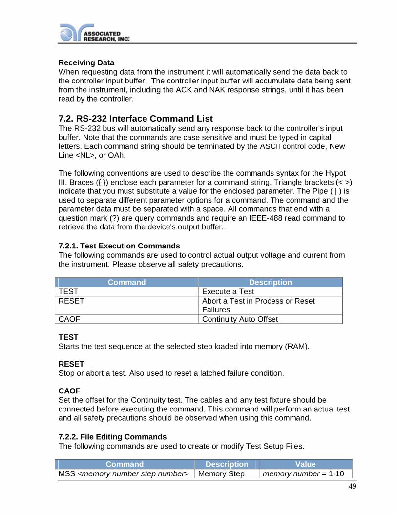
49
Receiving DataWhen requesting data from the instrument it will automatically send the data back tothe controller input buffer. The controller input buffer will accumulate data being sentfrom the instrument, including the ACK and NAK response strings, until it has beenread by the controller.
7.2. RS-232 Interface Command ListThe RS-232 bus will automatically send any response back to the controller's inputbuffer. Note that the commands are case sensitive and must be typed in capitalletters. Each command string should be terminated by the ASCII control code, NewLine <NL>, or OAh.
The following conventions are used to describe the commands syntax for the HypotIII. Braces ( ) enclose each parameter for a command string. Triangle brackets (< >)indicate that you must substitute a value for the enclosed parameter. The Pipe ( | ) isused to separate different parameter options for a command. The command and theparameter data must be separated with a space. All commands that end with aquestion mark (?) are query commands and require an IEEE-488 read command toretrieve the data from the device's output buffer.
7.2.1. Test Execution CommandsThe following commands are used to control actual output voltage and current fromthe instrument. Please observe all safety precautions.
Command DescriptionTEST Execute a TestRESET Abort a Test in Process or Reset
FailuresCAOF Continuity Auto Offset
TESTStarts the test sequence at the selected step loaded into memory (RAM).
RESETStop or abort a test. Also used to reset a latched failure condition.
CAOFSet the offset for the Continuity test. The cables and any test fixture should beconnected before executing the command. This command will perform an actual testand all safety precautions should be observed when using this command.
7.2.2. File Editing CommandsThe following commands are used to create or modify Test Setup Files.
Command Description ValueMSS <memory number step number> Memory Step memory number = 1-10

50
Select step number 1-3ACW Step Add ACW
testDCW Step Add DCW
testIR Step Add IR testSALL<memory+step,type,p1,p2,p3… > Add all
Parameters of aTest
MSS<memory number step number>Load a file by memory and step number. The first digit is the memory number and thesecond digit is the step number. Example: MSS <11> = memory 1 step 1
ACW, DCW, IRThese commands add the appropriate test type within the memory at the step locationthat has been selected. The parameters of the previous test type will be deleted andthe default values for the new test type will be recalled. If the same test type isselected that already exists, the default values will replace the previous parameters.
SALL <memory+step, type, p1, p2, p3… >This command edits all parameters in a memory and step. Parameters will be editedat the step location that has been selected. See the command summary tables to seethe specific test type for each of these commands. Example:SALL<01,ACW,1.24,10.00… >
The parameter <memory+step> indicated the memory and step number. Theparameter <type> indicated the test type. The values ACW, DCW, or IR must be used.The parameters <p1,p2> etc. indicate the individual settings for each test. Allparameters must be included with the command and should appear in the same orderthat is shown in the table below. Also, like the individual parameter editing commands,the unit should not be included with the value. Only the numeric value should beincluded in the command string. The list of parameters can also be found in thedefault parameters section of the manual, or refer to the Test Parameter Editingcommands section for the proper values. The parameter values should use completetext and not use the coded values that are associated with the individual parametersetting commands such as "ON" and "OFF" for toggle field.
ACW DCW IR1 Voltage Voltage Voltage2 Max Limit Max Limit Max Limit3 Min Limit Min Limit Min Limit4 Ramp Up Ramp Up Ramp Up5 Dwell Dwell Delay6 Ramp Down Ramp Down Ramp Down7 Arc Sense Arc Sense Connect
(ON/OFF)
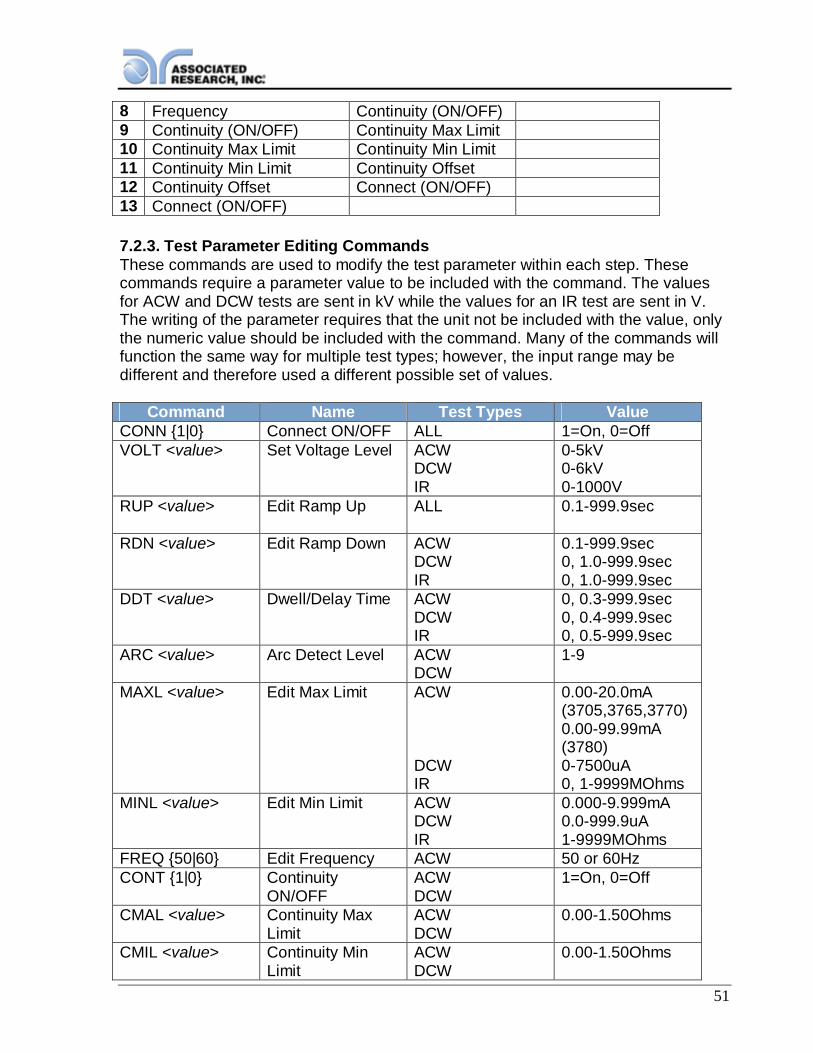
51
8 Frequency Continuity (ON/OFF)9 Continuity (ON/OFF) Continuity Max Limit10 Continuity Max Limit Continuity Min Limit11 Continuity Min Limit Continuity Offset12 Continuity Offset Connect (ON/OFF)13 Connect (ON/OFF)
7.2.3. Test Parameter Editing CommandsThese commands are used to modify the test parameter within each step. Thesecommands require a parameter value to be included with the command. The valuesfor ACW and DCW tests are sent in kV while the values for an IR test are sent in V.The writing of the parameter requires that the unit not be included with the value, onlythe numeric value should be included with the command. Many of the commands willfunction the same way for multiple test types; however, the input range may bedifferent and therefore used a different possible set of values.
Command Name Test Types ValueCONN 1|0 Connect ON/OFF ALL 1=On, 0=OffVOLT <value> Set Voltage Level ACW
DCWIR
0-5kV0-6kV0-1000V
RUP <value> Edit Ramp Up ALL 0.1-999.9sec
RDN <value> Edit Ramp Down ACWDCWIR
0.1-999.9sec0, 1.0-999.9sec0, 1.0-999.9sec
DDT <value> Dwell/Delay Time ACWDCWIR
0, 0.3-999.9sec0, 0.4-999.9sec0, 0.5-999.9sec
ARC <value> Arc Detect Level ACWDCW
1-9
MAXL <value> Edit Max Limit ACW
DCWIR
0.00-20.0mA(3705,3765,3770)0.00-99.99mA(3780)0-7500uA0, 1-9999MOhms
MINL <value> Edit Min Limit ACWDCWIR
0.000-9.999mA0.0-999.9uA1-9999MOhms
FREQ 50|60 Edit Frequency ACW 50 or 60HzCONT 1|0 Continuity
ON/OFFACWDCW
1=On, 0=Off
CMAL <value> Continuity MaxLimit
ACWDCW
0.00-1.50Ohms
CMIL <value> Continuity MinLimit
ACWDCW
0.00-1.50Ohms

52
COFF <value> Continuity Offset ACWDCW
0.00-0.50Ohms
7.2.4. System Parameter Editing Commands and Companion QueriesThese commands are used to modify the system parameters for the instrument.Thesecommands require a parameter value to be included with the command.
Command Name ValuePLC 1|0 PLC Remote ON/OFF 1=On, 0=OffSSTP 1|0 Single Step ON/OFF 1=On, 0=OffSGFI 1|0 Smart GFI 1=On, 0=OffALAR <value> Alarm Level 0-9CNTR <value> Contrast Level 0-9RLT L|A|P Result Setting L=Last, A=All, P=P/F
7.2.5. Query CommandsThese query commands will retrieve data from the instrument. These commandsinclude functions for retrieving test data, test results and remote hardware.
Command Name Value*IDN? Identification
QueryAssociated Research Inc., ModelNumber, Serial Number, FirmwareRevision
TD? List TestingData
Data from test in Process
RD <step number>? Result DataQuery
1-3
SALL? List StepParameters
Response:SALLmemory+step,type,p1,p2,p3…
RR? Read ResetQuery
1=Open, 0=Closed
RI? Read InterlockQuery
1=Open, 0=Closed
*IDN?Read the instrument identification string. Company = Associated Research Inc.
TD?Read the active data being displayed on the LCD display while the test is in process. Itwill also read the last data taken when the test sequence has completed. Eachparameter is separated by commas and includes step number, test type, test status,and metering. The syntax for this command response is memory - step, test type,status, meter 1, meter 2, meter 3. ACW test displays 4 meters. Each meter willcontain both the value and the units. In the case of DCW current where both uA and
53
mA are used on the display, the command response will always indicate the current inuA for example 2.0mA will respond with 2000uA.
RD <step number>?Read the results for an individual step. The step number is the actual step numberthat has been saved within the file, not the order of which the steps were executed.For example if the test was executed starting from step 3 and ending with step 5 thenthe first step test results will be found in location 3 not in location 1. Each parameter isseparated by commas and includes step number, test type, test status, and metering.The syntax for this command response is memory - step, test type, status, meter 1,meter 2, meter 3. ACW test displays 4 meters. Each meter will contain both the valueand the units. In the case of DCW current where both uA and mA are used on thedisplay the command response will always indicate the current in uA for example2.0mA will respond with 2000uA.
SALL?Lists all the step parameters for the step currently selected. Each parameter isseparated by commas and includes memory and step number, test type, andparameter values. The syntax for this command response is SALL memory+step,type, parameter 1, parameter 2, parameter 3… . In the case of DCW current whereboth uA and mA are used on the display, the command response will always indicatethe current in uA for example 2.0mA will respond with 2000uA.
RR?Read the remote Reset input signal. When the remote reset has be activated byclosing thecontacts the query will return a value of 0 to indicate the instrument is being Reset.
RI?Read the remote Interlock input signal. When the remote Interlock has be activated byopening the contacts the query will return a value of 1 to indicate the instrument is inthe Interlock state and will not be able to generate output voltage or current.
7.2.6. Query Commands and Displayed MessagesWhile performing tests, a number of messages will be displayed to indicate the teststate or test results. These messages are displayed in the status area of the screen,located on the first line at the top of the LCD. Query commands are used to retrievethis information remotely. The following examples outline the syntax for variousdisplayed messages using the TD? and RD X? query commands.
NOTE: the format for the TD? and RD X? query commands:memory-step,test type,status,meter1,meter2,meter3.
Below is an example response showing descriptions of the individual parameters foreach test type:

54
DisplayedMessage Example Query Response
Memory-Step
TestType Status Meter 1
(Voltage)Meter 2
(LeakageCurrent)
Meter 3(Timer)
Dwell M1-1 ACW Dwell 0.30kV 0.296mA 0.5sDwell M1-2 DCW Dwell 1.00kVDwell M1-3 IR Dwell 0.50kV
For example, if a 3700 unit running an ACW test at 3800V and reading 2.3mA leakagecurrent was queried with the TD? command 1.2sec into the dwell cycle, it wouldrespond with:
M1-1,ACW,Dwell,3.80,2.30,1.2
The table below shows queries response examples for every displayed message type:
Displayed Message Example Query ResponseDwell M1-1 ,ACW,Dwell,0.30kV,0.296mA,0.5sDelay M1-1 ,ACW,Delay,0.30kV,0.192mA,0.2sRamp UP M1-1 ,ACW,Ramp UP,0.15kV,0.090mA,0.1sRamp DN M1-1 ,ACW,Ramp DN,0.10kV,0.122mA,10.0sPass M1-1 ,ACW,Pass,1.00kV,0.296mA,2.0sAbort M1-1 ,ACW,Abort,0.30kV,0.291mA,0.4sMax Fail M1-1 ,ACW,Max Fail,0.30kV,0.296mA,0.2sMin Fail M1-1 ,ACW,Min Fail,0.30kV,0.296mA,0.2sCont Max M1-1 ,ACW,Cont Max,0.30kV,0.296mA,0.2sCont Min M1-1 ,ACW,Cont Min,0.30kV,0.296mA,0.2sArc Fail M1-1 ,ACW,Arc Fail,1.97kV,0.613mA,1.2sShort M1-1 ,ACW,Short,1.23kV,0.720mA,0.5sBreakdown M1-1 ,ACW,Breakdown,0.30kV,0.300mA,10.0sGND Fault M1-1 ,ACW,GND Fault,0.40kV,0.290mA,11.0s

55
8. OPTIONSIntroductionThis section contains descriptions of available factory installed options at the time ofthis printing. The list of options contains an option code number that can bereferenced on the data plate on the rear panel of the unit.
Option LabelOn the rear panel of the instrument, you will find a label that contains the option code.
For example, your options code would appear as follows:Fitted with option 01… ......................................................... OPT: 01Fitted with option 01 and 02................................................ OPT: 0102
Hypot III Options
Option ListCode Description01 High Resolution IR Limits02 5mA Output Current03 5Ω Continuity04 PLC Ready Output05 3mA Output Current
Description
01 High Resolution IR Limits (3770 only)The High Resolution IR Limits option increases the resolution of the Max and Min trippoint limits from 1MΩ to 0.1MΩ, in the range of 0.0 to 999.9MΩ.
The Max and Min Lmt set points automatically range while being edited according tothe specification table below. This is unique only to this feature because this optionhas multiple ranges.
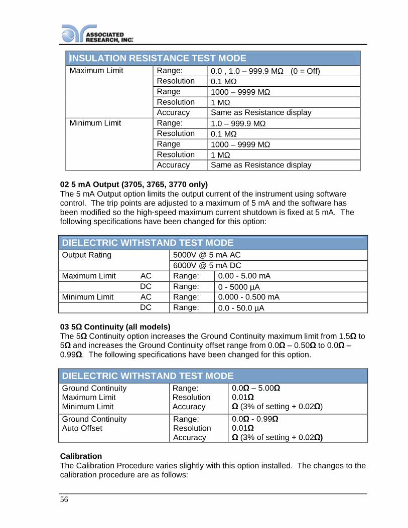
56
INSULATION RESISTANCE TEST MODEMaximum Limit Range: 0.0 , 1.0 – 999.9 MΩ (0 = Off)
Resolution 0.1 MΩRange 1000 – 9999 MΩResolution 1 MΩAccuracy Same as Resistance display
Minimum Limit Range: 1.0 – 999.9 MΩResolution 0.1 MΩRange 1000 – 9999 MΩResolution 1 MΩAccuracy Same as Resistance display
02 5 mA Output (3705, 3765, 3770 only)The 5 mA Output option limits the output current of the instrument using softwarecontrol. The trip points are adjusted to a maximum of 5 mA and the software hasbeen modified so the high-speed maximum current shutdown is fixed at 5 mA. Thefollowing specifications have been changed for this option:
DIELECTRIC WITHSTAND TEST MODEOutput Rating 5000V @ 5 mA AC
6000V @ 5 mA DCMaximum Limit AC Range: 0.00 - 5.00 mA DC Range: 0 - 5000 µAMinimum Limit AC Range: 0.000 - 0.500 mA DC Range: 0.0 - 50.0 µA
03 5 Continuity (all models)The 5 Continuity option increases the Ground Continuity maximum limit from 1.5 to5 and increases the Ground Continuity offset range from 0.0 – 0.50 to 0.0 –0.99 . The following specifications have been changed for this option.
DIELECTRIC WITHSTAND TEST MODEGround ContinuityMaximum LimitMinimum Limit
Range:ResolutionAccuracy
0.0 –5.000.01
(3% of setting + 0.02 )Ground ContinuityAuto Offset
Range:ResolutionAccuracy
0.0 - 0.990.01
(3% of setting + 0.02 )
CalibrationThe Calibration Procedure varies slightly with this option installed. The changes to thecalibration procedure are as follows:
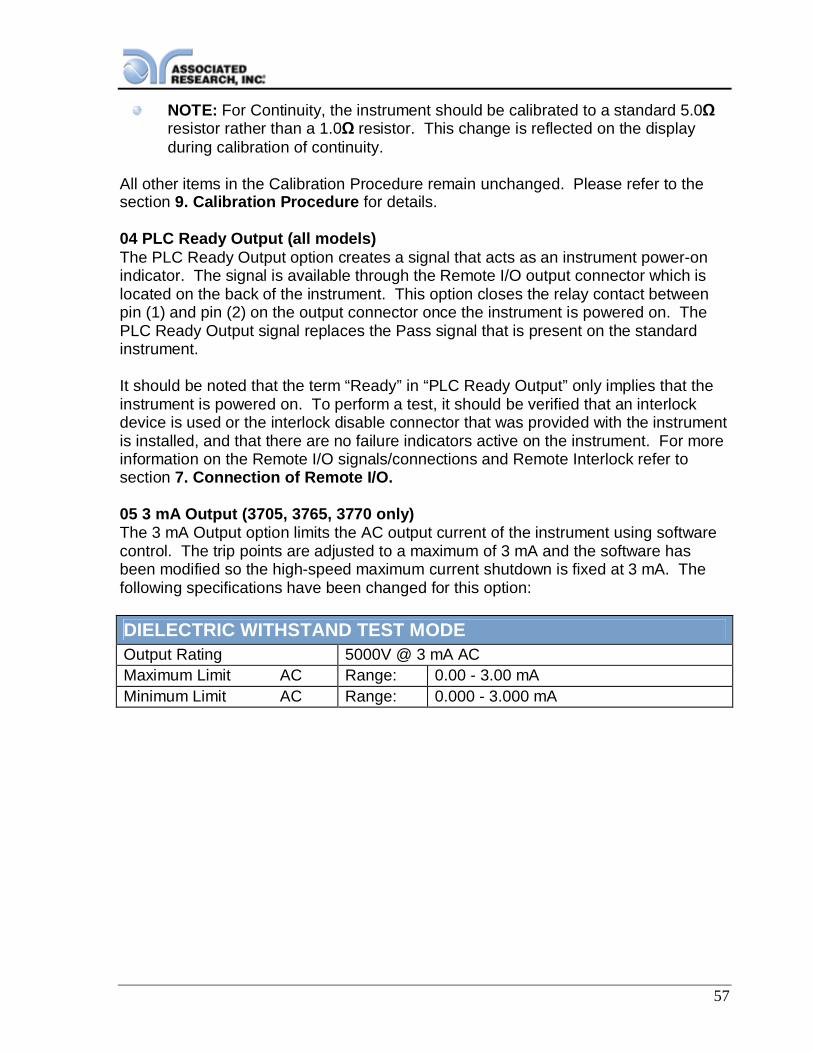
57
NOTE: For Continuity, the instrument should be calibrated to a standard 5.0resistor rather than a 1.0 resistor. This change is reflected on the displayduring calibration of continuity.
All other items in the Calibration Procedure remain unchanged. Please refer to thesection 9. Calibration Procedure for details.
04 PLC Ready Output (all models)The PLC Ready Output option creates a signal that acts as an instrument power-onindicator. The signal is available through the Remote I/O output connector which islocated on the back of the instrument. This option closes the relay contact betweenpin (1) and pin (2) on the output connector once the instrument is powered on. ThePLC Ready Output signal replaces the Pass signal that is present on the standardinstrument.
It should be noted that the term “Ready” in “PLC Ready Output” only implies that theinstrument is powered on. To perform a test, it should be verified that an interlockdevice is used or the interlock disable connector that was provided with the instrumentis installed, and that there are no failure indicators active on the instrument. For moreinformation on the Remote I/O signals/connections and Remote Interlock refer tosection 7. Connection of Remote I/O.
05 3 mA Output (3705, 3765, 3770 only)The 3 mA Output option limits the AC output current of the instrument using softwarecontrol. The trip points are adjusted to a maximum of 3 mA and the software hasbeen modified so the high-speed maximum current shutdown is fixed at 3 mA. Thefollowing specifications have been changed for this option:
DIELECTRIC WITHSTAND TEST MODEOutput Rating 5000V @ 3 mA ACMaximum Limit AC Range: 0.00 - 3.00 mAMinimum Limit AC Range: 0.000 - 3.000 mA
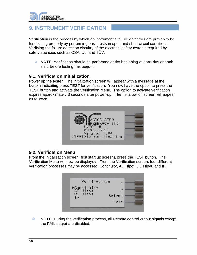
58
9. INSTRUMENT VERIFICATION
Verification is the process by which an instrument’s failure detectors are proven to befunctioning properly by performing basic tests in open and short circuit conditions.Verifying the failure detection circuitry of the electrical safety tester is required bysafety agencies such as CSA, UL, and TÜV.
NOTE: Verification should be performed at the beginning of each day or eachshift, before testing has begun.
9.1. Verification InitializationPower up the tester. The initialization screen will appear with a message at thebottom indicating press TEST for verification. You now have the option to press theTEST button and activate the Verification Menu. The option to activate verificationexpires approximately 3 seconds after power-up. The Initialization screen will appearas follows:
9.2. Verification MenuFrom the Initialization screen (first start up screen), press the TEST button. TheVerification Menu will now be displayed. From the Verification screen, four differentverification processes may be accessed: Continuity, AC Hipot, DC Hipot, and IR.
NOTE: During the verification process, all Remote control output signals exceptthe FAIL output are disabled.
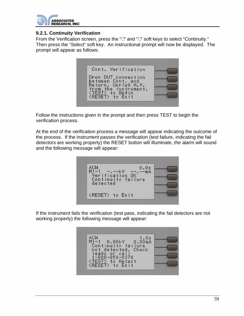
59
9.2.1. Continuity VerificationFrom the Verification screen, press the “∧” and “∨” soft keys to select “Continuity.”Then press the “Select” soft key. An instructional prompt will now be displayed. Theprompt will appear as follows:
Follow the instructions given in the prompt and then press TEST to begin theverification process.
At the end of the verification process a message will appear indicating the outcome ofthe process. If the instrument passes the verification (test failure, indicating the faildetectors are working properly) the RESET button will illuminate, the alarm will soundand the following message will appear:
If the instrument fails the verification (test pass, indicating the fail detectors are notworking properly) the following message will appear:

60
9.2.2. AC Hipot VerificationFrom the Verification screen, press the “∧” and “∨” soft keys to select “AC Hipot.”Then press the “Select” soft key. An instructional prompt will now be displayed. Theprompt will appear as follows:
Follow the instructions given in the prompt and then press TEST to begin theverification process.
At the end of the verification process a message will appear indicating the outcome ofthe process. If the instrument passes the verification (test failure, indicating the faildetectors are working properly) the RESET button will illuminate, the alarm will soundand the following message will appear:
If the instrument fails the verification (test pass, indicating the fail detectors are notworking properly) the following message will appear:
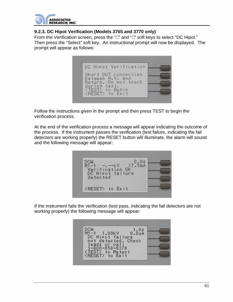
61
9.2.3. DC Hipot Verification (Models 3765 and 3770 only)From the Verification screen, press the “∧” and “∨” soft keys to select “DC Hipot.”Then press the “Select” soft key. An instructional prompt will now be displayed. Theprompt will appear as follows:
Follow the instructions given in the prompt and then press TEST to begin theverification process.
At the end of the verification process a message will appear indicating the outcome ofthe process. If the instrument passes the verification (test failure, indicating the faildetectors are working properly) the RESET button will illuminate, the alarm will soundand the following message will appear:
If the instrument fails the verification (test pass, indicating the fail detectors are notworking properly) the following message will appear:
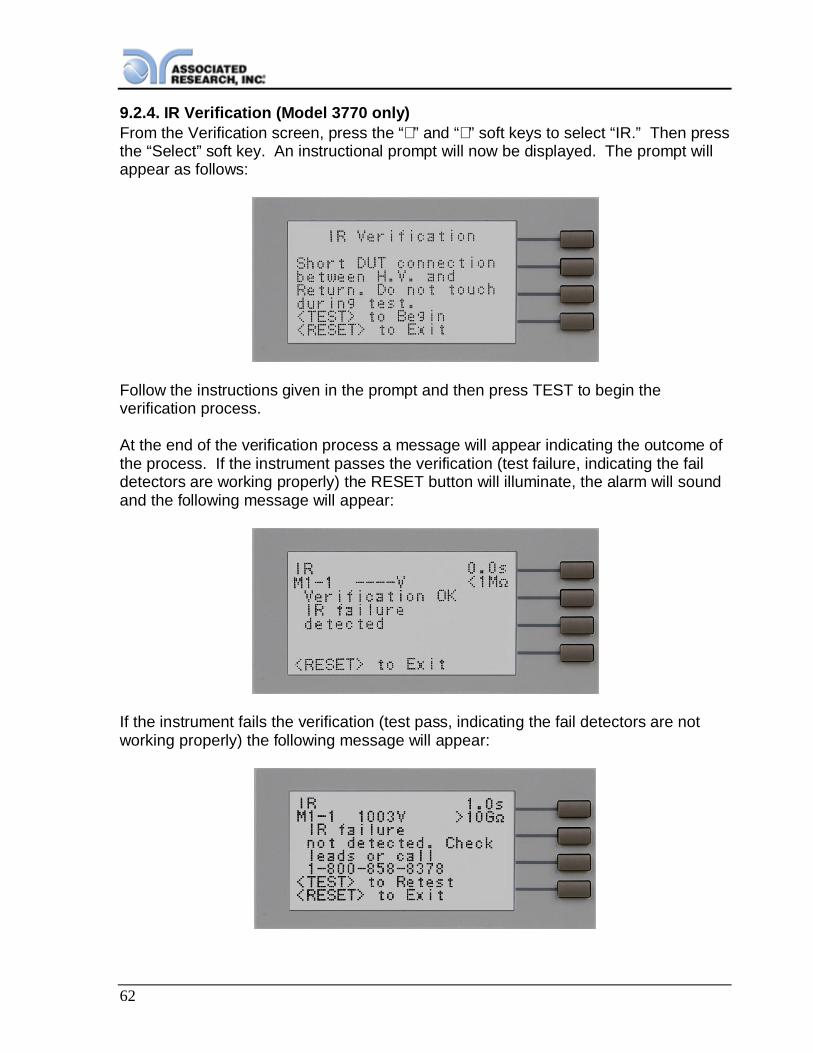
62
9.2.4. IR Verification (Model 3770 only)From the Verification screen, press the “∧” and “∨” soft keys to select “IR.” Then pressthe “Select” soft key. An instructional prompt will now be displayed. The prompt willappear as follows:
Follow the instructions given in the prompt and then press TEST to begin theverification process.
At the end of the verification process a message will appear indicating the outcome ofthe process. If the instrument passes the verification (test failure, indicating the faildetectors are working properly) the RESET button will illuminate, the alarm will soundand the following message will appear:
If the instrument fails the verification (test pass, indicating the fail detectors are notworking properly) the following message will appear:

63
This instrument has beenfully calibrated at the factoryin accordance to ourpublished specifications andwith standards traceable tothe National Institute ofStandards & Technology(NIST).
DID YOU KNOW?
10. CALIBRATION
You will find in this manual a copy of the"Certificate of Calibration". It is recommended thatyou have this instrument recertified at least onceper year. Associated Research, Inc. recommendsyou use "Calibration Standards" that are NISTtraceable or traceable to agencies recognized byNIST to keep this instrument within publishedspecifications. Unless necessary, do notrecalibrate the instrument within the first 12months.
End user metrology standards or practices mayvary. These metrology standards determine the
measurement uncertainty ratio of the calibration standards being used. Calibrationadjustments can only be made in the Calibration mode and calibration checks orverifications can only be made while operating in Test mode.
NOTE: Verification should be performed before and after calibration.Calibration effects will only be noticeable after exiting calibration mode.
10.1. Warranty RequirementsAssociated Research, Inc. offers a standard one-year manufacturer’s warranty. Thiswarranty can be extended an additional four years provided that the instrument isreturned each year to Associated Research, Inc. for its annual recertification. In orderto be eligible for the extended warranty instruments must be returned to AssociatedResearch, Inc. for certification service at least once every twelve months.
A return material authorization number (RMA) must be obtained from AssociatedResearch, Inc. before returning this instrument for calibration. To obtain an RMAnumber or for information regarding our warranty, please contact our customersupport representatives at 1-800-858-TEST (8378) or setup an RMA online athttp://www.asresearch.com/support/RMA-request.aspx.
Required Calibration Equipment 0 - 5 KV AC/DC Metered Voltage Divider. 20 mA AC, 10 mA DC Ammeter. 1Ω, 0.25 watt resistor, 250 volt. 50MΩ, 0.25 watt resistor, 1000 volt. 500MΩ, 0.25 watt resistor, 1000 volt. 100KΩ, 175 watt resistor, 4000 volt. 1MΩ, 20 watt resistor, 4000 volt.

64
10.2. Warranty RequirementsAssociated Research, Inc. offers a standard 1-Year manufacturer’s warranty. Thiswarranty can be extended an additional (4) years provided that the instrument isreturned each year to Associated Research, Inc. for its annual recertification. In orderto be eligible for the extended warranty instruments must be returned to AssociatedResearch, Inc. for certification service at least once every twelve months.
A return material authorization number (RMA) must be obtained from AssociatedResearch, Inc. before returning this instrument for calibration. To obtain an RMAnumber or for information regarding our warranty, please contact our customersupport representatives at 1-800-858-TEST (8378) or setup an RMA online athttp://www.asresearch.com/support/RMA-request.aspx
10.3. Calibration InitializationPress and hold the Calibration key on the rear panel with a pen, pencil or smallscrewdriver while powering on the Hypot III. The Hypot III enters calibration modeafter the power on sequence is complete. The Calibration screen will appear asfollows for the 3705, 3765 and 3770:
The Calibration screen will appear as follows for the 3780:
Calibration of ParametersFrom the Calibration screens, use the “∨” soft key to scroll the cursor to the parameteryou wish to calibrate. Once the cursor is pointing to the parameter you wish tocalibrate, press the “Select” soft key. A Calibration Prompt screen will now appear
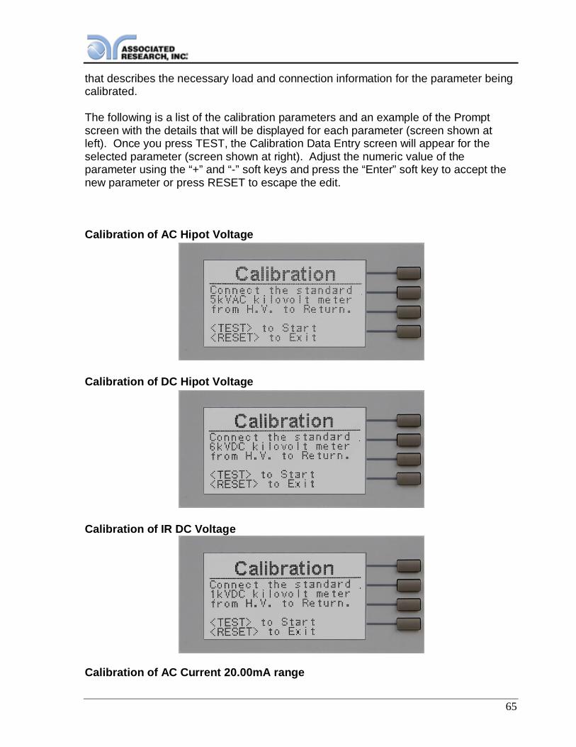
65
that describes the necessary load and connection information for the parameter beingcalibrated.
The following is a list of the calibration parameters and an example of the Promptscreen with the details that will be displayed for each parameter (screen shown atleft). Once you press TEST, the Calibration Data Entry screen will appear for theselected parameter (screen shown at right). Adjust the numeric value of theparameter using the “+” and “-” soft keys and press the “Enter” soft key to accept thenew parameter or press RESET to escape the edit.
Calibration of AC Hipot Voltage
Calibration of DC Hipot Voltage
Calibration of IR DC Voltage
Calibration of AC Current 20.00mA range

66
Calibration of AC Current 99.99mA range (3780 Only)
Calibration of AC Current 3.50mA range
Calibration of DC Current 7.50mA range
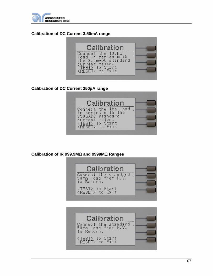
67
Calibration of DC Current 3.50mA range
Calibration of DC Current 350µA range
Calibration of IR 999.9MΩ and 9999MΩ Ranges

68
Calibration of Continuity, Step 1
Calibration of Continuity, Step 2
Calibration of Continuity, Step 3
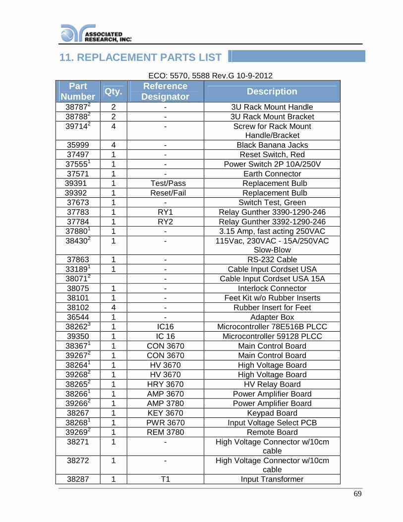
69
11. REPLACEMENT PARTS LISTECO: 5570, 5588 Rev.G 10-9-2012
PartNumber Qty. Reference
Designator Description387872 2 - 3U Rack Mount Handle387882 2 - 3U Rack Mount Bracket397142 4 - Screw for Rack Mount
Handle/Bracket35999 4 - Black Banana Jacks37497 1 - Reset Switch, Red375551 1 - Power Switch 2P 10A/250V37571 1 - Earth Connector
39391 1 Test/Pass Replacement Bulb39392 1 Reset/Fail Replacement Bulb37673 1 - Switch Test, Green37783 1 RY1 Relay Gunther 3390-1290-24637784 1 RY2 Relay Gunther 3392-1290-246378801 1 - 3.15 Amp, fast acting 250VAC384302 1 - 115Vac, 230VAC - 15A/250VAC
Slow-Blow37863 1 - RS-232 Cable331891 1 - Cable Input Cordset USA380712 - Cable Input Cordset USA 15A38075 1 - Interlock Connector38101 1 - Feet Kit w/o Rubber Inserts38102 4 - Rubber Insert for Feet36544 1 - Adapter Box382623 1 IC16 Microcontroller 78E516B PLCC39350 1 IC 16 Microcontroller 59128 PLCC383671 1 CON 3670 Main Control Board392672 1 CON 3670 Main Control Board382641 1 HV 3670 High Voltage Board392682 1 HV 3670 High Voltage Board382652 1 HRY 3670 HV Relay Board382661 1 AMP 3670 Power Amplifier Board392662 1 AMP 3780 Power Amplifier Board38267 1 KEY 3670 Keypad Board382681 1 PWR 3670 Input Voltage Select PCB392692 1 REM 3780 Remote Board38271 1 - High Voltage Connector w/10cm
cable38272 1 - High Voltage Connector w/10cm
cable38287 1 T1 Input Transformer

70
382881 1 T2 Output High Voltage Transformer392772 1 T2 Output High Voltage Transformer38320 1 - 128 x 64 Graphic Display
04040A-08
1 - High Voltage Output cable
02100A-13
2 - Return cable
13705, 3765, 3770 Only23780 Only33705, 3765, 3770 Firmware 1.04 and below
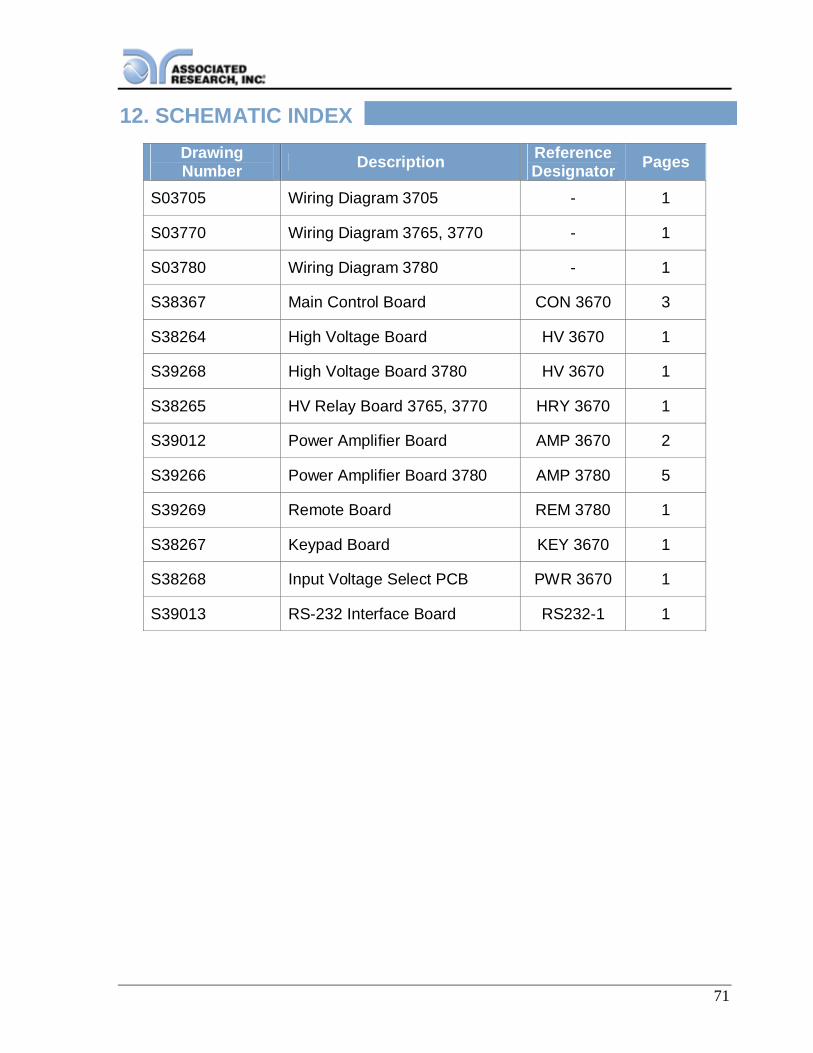
71
12. SCHEMATIC INDEXDrawingNumber Description Reference
Designator Pages
S03705 Wiring Diagram 3705 - 1
S03770 Wiring Diagram 3765, 3770 - 1
S03780 Wiring Diagram 3780 - 1
S38367 Main Control Board CON 3670 3
S38264 High Voltage Board HV 3670 1
S39268 High Voltage Board 3780 HV 3670 1
S38265 HV Relay Board 3765, 3770 HRY 3670 1
S39012 Power Amplifier Board AMP 3670 2
S39266 Power Amplifier Board 3780 AMP 3780 5
S39269 Remote Board REM 3780 1
S38267 Keypad Board KEY 3670 1
S38268 Input Voltage Select PCB PWR 3670 1
S39013 RS-232 Interface Board RS232-1 1
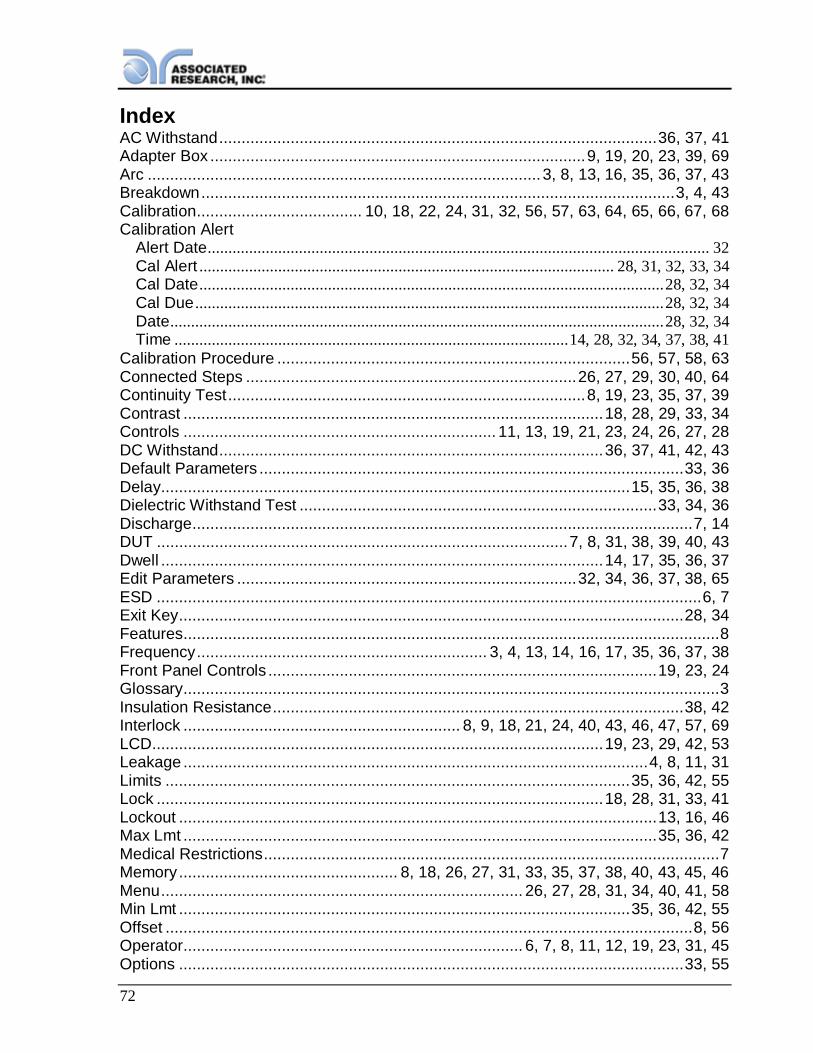
72
IndexAC Withstand .................................................................................................. 36, 37, 41Adapter Box .................................................................................... 9, 19, 20, 23, 39, 69Arc ........................................................................................ 3, 8, 13, 16, 35, 36, 37, 43Breakdown .......................................................................................................... 3, 4, 43Calibration ..................................... 10, 18, 22, 24, 31, 32, 56, 57, 63, 64, 65, 66, 67, 68Calibration Alert
Alert Date ......................................................................................................................... 32Cal Alert .................................................................................................... 28, 31, 32, 33, 34Cal Date ................................................................................................................ 28, 32, 34Cal Due ................................................................................................................. 28, 32, 34Date ....................................................................................................................... 28, 32, 34Time ............................................................................................... 14, 28, 32, 34, 37, 38, 41
Calibration Procedure ............................................................................... 56, 57, 58, 63Connected Steps .......................................................................... 26, 27, 29, 30, 40, 64Continuity Test ................................................................................ 8, 19, 23, 35, 37, 39Contrast .............................................................................................. 18, 28, 29, 33, 34Controls ...................................................................... 11, 13, 19, 21, 23, 24, 26, 27, 28DC Withstand ...................................................................................... 36, 37, 41, 42, 43Default Parameters ............................................................................................... 33, 36Delay ......................................................................................................... 15, 35, 36, 38Dielectric Withstand Test ................................................................................ 33, 34, 36Discharge ................................................................................................................ 7, 14DUT ............................................................................................ 7, 8, 31, 38, 39, 40, 43Dwell ................................................................................................... 14, 17, 35, 36, 37Edit Parameters ............................................................................ 32, 34, 36, 37, 38, 65ESD .......................................................................................................................... 6, 7Exit Key ................................................................................................................. 28, 34Features ........................................................................................................................ 8Frequency ................................................................. 3, 4, 13, 14, 16, 17, 35, 36, 37, 38Front Panel Controls ....................................................................................... 19, 23, 24Glossary ........................................................................................................................ 3Insulation Resistance ............................................................................................ 38, 42Interlock .............................................................. 8, 9, 18, 21, 24, 40, 43, 46, 47, 57, 69LCD ..................................................................................................... 19, 23, 29, 42, 53Leakage ........................................................................................................ 4, 8, 11, 31Limits ........................................................................................................ 35, 36, 42, 55Lock .................................................................................................... 18, 28, 31, 33, 41Lockout ........................................................................................................... 13, 16, 46Max Lmt .......................................................................................................... 35, 36, 42Medical Restrictions ...................................................................................................... 7Memory ................................................. 8, 18, 26, 27, 31, 33, 35, 37, 38, 40, 43, 45, 46Menu ................................................................................. 26, 27, 28, 31, 34, 40, 41, 58Min Lmt ..................................................................................................... 35, 36, 42, 55Offset ...................................................................................................................... 8, 56Operator ............................................................................ 6, 7, 8, 11, 12, 19, 23, 31, 45Options ................................................................................................................. 33, 55
ParametersSystem Parameters ............................................................................................. 28, 29, 34Test Parameters ...................................................................................... 18, 26, 28, 35, 36
PLC ................................................................................................. 8, 28, 29, 33, 34, 45Power .................................................................................................................. 4, 6, 11Power Factor................................................................................................................. 4Programming .............................................................................................................. 26Ramping ....................................................................................................................... 8Rear Panel Controls .............................................................................................. 11, 21Receptacle .......................................................................................... 18, 21, 24, 39, 44Regulation ............................................................................................................. 14, 17Remote ................... 8, 18, 21, 24, 28, 29, 33, 34, 40, 42, 43, 44, 45, 46, 47, 48, 57, 58Remote Interlock ........................................................................... 18, 40, 43, 46, 47, 57Resistance ................................................................ 4, 7, 11, 15, 35, 37, 38, 41, 42, 56Return ......................................................................................................................... 11Reviewing Test Results .............................................................................................. 31RS-232 .................................................................................................................. 21, 24Safety ................................................................................................ 2, ii, 3, 5, 7, 11, 18Safety Symbols ............................................................................................................. 3Schematic ................................................................................................................... 70Schematic Index ......................................................................................................... 70Security ....................................................................................................... 8, 18, 31, 33Sequence ............................................................................................ 27, 29, 30, 40, 64Service .......................................................................................... 1, 3, 5, 10, 43, 63, 64Service Interval ............................................................................................................. 5Setup .................................................................................. 8, 11, 19, 23, 28, 33, 34, 41Short ............................................................................................................... 15, 43, 58Single Step ........................................................................................... 8, 28, 29, 33, 34Smart GFI ................................................................................................. 18, 28, 31, 33Specifications ........................................................................................................ 13, 16System Parameters .................................................................................. 28, 29, 33, 34Test Parameters ............................................................................. 8, 18, 26, 28, 34, 36Test Station ............................................................................................................... 6, 7Trip Point ...................................................................................... 35, 36, 37, 38, 42, 55UL ............................................................................................................................... 58Unpacking ..................................................................................................................... 9Verification .......................................................................................... 58, 59, 60, 61, 62Warranty ....................................................................................................... 1, 2, 63, 64Warranty Policies .......................................................................................................... 1