operation / installation manual -...
TRANSCRIPT
Operation / Installation Manual
– Do not store or use gasoline or other flammable vapors and liquids in the vicinity of this or any other appliance.
– WHAT TO DO IF YOU SMELL GAS
• Do not try to light any appliance.
• Do not touch any electrical switch; do not use any phone in your building.
• Immediately call your gas supplier from a neighbor's phone. Follow the gas supplier's instructions.
• If you cannot reach your gas supplier, call the fire department.
– Installation and service must be performed by a qualified installer, service agency or the gas supplier.
WARNING: If the information in these instructions is not followed exactly, a fire or explosion may result causing property damage, personal injury or death.
(Residential and Commercial indoor unit)
To Suit Models:
REU-V2520FFU...... R53 REU-V2520FFUC... C53REU-V2532FFU...... R85REU-V2532FFUC.... C85
ANS Z21.10.3=CSA 4.3
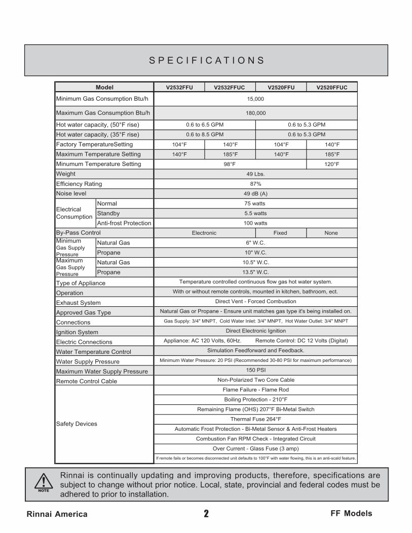
V2532FFU
15,000
180,000
104°F 140°F 104°F 140°F
140°F 185°F 140°F 185°F
98°F 120°F
49 Lbs.
87%
49 dB (A)
Normal 75 watts
Standby 5.5 watts
Anti-frost Protection 100 watts
Electronic Fixed None
Natural Gas 6" W.C.
Propane 10" W.C.
Natural Gas 10.5" W.C.
Propane 13.5" W.C.
Ignition System
Water Temperature Control
Water Supply Pressure
Electric Connections
Minimum Water Pressure: 20 PSI (Recommended 30-80 PSI for maximum performance)
Safety Devices
Maximum Water Supply Pressure
Remote Control CableFlame Failure - Flame Rod
Boiling Protection - 210°F
Over Current - Glass Fuse (3 amp)
If remote fails or becomes disconnected unit defaults to 100°F with water flowing, this is an anti-scald feature.
Remaining Flame (OHS) 207°F Bi-Metal Switch
Thermal Fuse 264°F
Direct Electronic Ignition
Appliance: AC 120 Volts, 60Hz. Remote Control: DC 12 Volts (Digital)
Simulation Feedforward and Feedback.
Gas Supply: 3/4" MNPT, Cold Water Inlet: 3/4" MNPT, Hot Water Outlet: 3/4" MNPT
Model
Minimum Gas Consumption Btu/h
Maximum Gas Consumption Btu/h
With or without remote controls, mounted in kitchen, bathroom, ect.
Connections
By-Pass ControlMinimumGas Supply PressureMaximumGas Supply Pressure
Type of Appliance
Operation
Exhaust System
Approved Gas Type
ElectricalConsumption
Hot water capacity, (50°F rise)
Hot water capacity, (35°F rise)
Factory TemperatureSetting
Maximum Temperature Setting
Minumum Temperature Setting
Weight
Noise level
Efficiency Rating
Automatic Frost Protection - Bi-Metal Sensor & Anti-Frost Heaters
Combustion Fan RPM Check - Integrated Circuit
150 PSI
Non-Polarized Two Core Cable
0.6 to 5.3 GPM
0.6 to 5.3 GPM
Direct Vent - Forced Combustion
Natural Gas or Propane - Ensure unit matches gas type it's being installed on.
0.6 to 6.5 GPM
0.6 to 8.5 GPM
Temperature controlled continuous flow gas hot water system.
V2532FFUC V2520FFU V2520FFUC
2Rinnai America FF Models
S P E C I F I C A T I O N S
Rinnai is continually updating and improving products, therefore, specifications are subject to change without prior notice. Local, state, provincial and federal codes must be adhered to prior to installation.
3Rinnai America FF Models
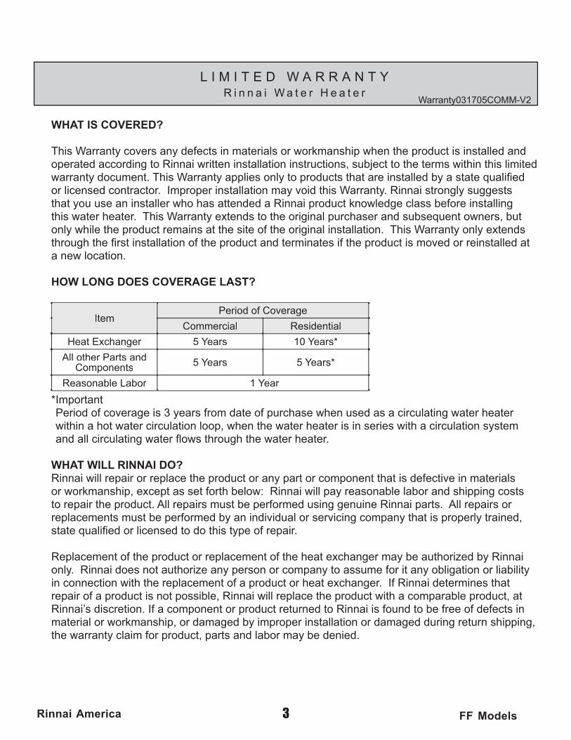
WHAT IS COVERED?
This Warranty covers any defects in materials or workmanship when the product is installed and operated according to Rinnai written installation instructions, subject to the terms within this limited warranty document. This Warranty applies only to products that are installed by a state qualifi ed or licensed contractor. Improper installation may void this Warranty. Rinnai strongly suggests that you use an installer who has attended a Rinnai product knowledge class before installing this water heater. This Warranty extends to the original purchaser and subsequent owners, but only while the product remains at the site of the original installation. This Warranty only extends through the fi rst installation of the product and terminates if the product is moved or reinstalled at a new location.
HOW LONG DOES COVERAGE LAST?
ItemPeriod of Coverage
Commercial Residential
Heat Exchanger 5 Years 10 Years*
All other Parts and Components 5 Years 5 Years*
Reasonable Labor 1 Year
*ImportantPeriod of coverage is 3 years from date of purchase when used as a circulating water heater within a hot water circulation loop, when the water heater is in series with a circulation system and all circulating water fl ows through the water heater.
WHAT WILL RINNAI DO?Rinnai will repair or replace the product or any part or component that is defective in materials or workmanship, except as set forth below: Rinnai will pay reasonable labor and shipping costs to repair the product. All repairs must be performed using genuine Rinnai parts. All repairs or replacements must be performed by an individual or servicing company that is properly trained, state qualifi ed or licensed to do this type of repair.
Replacement of the product or replacement of the heat exchanger may be authorized by Rinnai only. Rinnai does not authorize any person or company to assume for it any obligation or liability in connection with the replacement of a product or heat exchanger. If Rinnai determines that repair of a product is not possible, Rinnai will replace the product with a comparable product, at Rinnai’s discretion. If a component or product returned to Rinnai is found to be free of defects in material or workmanship, or damaged by improper installation or damaged during return shipping, the warranty claim for product, parts and labor may be denied.
Warranty031705COMM-V2
L I M I T E D W A R R A N T YR i n n a i W a t e r H e a t e r
4Rinnai America FF Models
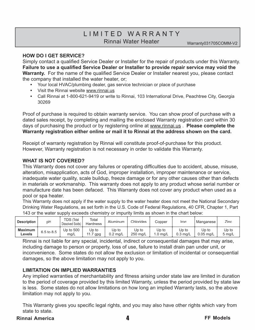
HOW DO I GET SERVICE?Simply contact a qualifi ed Service Dealer or Installer for the repair of products under this Warranty. Failure to use a qualifi ed Service Dealer or Installer to provide repair service may void the Warranty. For the name of the qualifi ed Service Dealer or Installer nearest you, please contact the company that installed the water heater, or;
• Your local HVAC/plumbing dealer, gas service technician or place of purchase • Visit the Rinnai website www.rinnai.us • Call Rinnai at 1-800-621-9419 or write to Rinnai, 103 International Drive, Peachtree City, Georgia
30269
Proof of purchase is required to obtain warranty service. You can show proof of purchase with a dated sales receipt, by completing and mailing the enclosed Warranty registration card within 30 days of purchasing the product or by registering online at www.rinnai.us . Please complete the Warranty registration either online or mail it to Rinnai at the address shown on the card.
Receipt of warranty registration by Rinnai will constitute proof-of-purchase for this product. However, Warranty registration is not necessary in order to validate this Warranty.
WHAT IS NOT COVERED?This Warranty does not cover any failures or operating diffi culties due to accident, abuse, misuse, alteration, misapplication, acts of God, improper installation, improper maintenance or service, inadequate water quality, scale buildup, freeze damage or for any other causes other than defects in materials or workmanship. This warranty does not apply to any product whose serial number or manufacture date has been defaced. This Warranty does not cover any product when used as a pool or spa heater. This Warranty does not apply if the water supply to the water heater does not meet the National Secondary Drinking Water Regulations, as set forth in the U.S. Code of Federal Regulations, 40 CFR, Chapter 1, Part 143 or the water supply exceeds chemistry or impurity limits as shown in the chart below:
Description pH TDS (Total Dissoived Soids)
Total Hardness Aluminum Chlorides Copper Iron Manganese Zinc
Maximum Levels 6.5 to 8.5 Up to 500
mg/LUp to
11.7 gpgUp to
0.2 mg/LUp to
250 mg/LUp to
1.0 mg/LUp to
0.3 mg/LUp to
0.05 mg/LUp to
5 mg/L
Rinnai is not liable for any special, incidental, indirect or consequential damages that may arise, including damage to person or property, loss of use, failure to install drain pan under unit, or inconvenience. Some states do not allow the exclusion or limitation of incidental or consequential damages, so the above limitation may not apply to you.
LIMITATION ON IMPLIED WARRANTIESAny implied warranties of merchantability and fi tness arising under state law are limited in duration to the period of coverage provided by this limited Warranty, unless the period provided by state law is less. Some states do not allow limitations on how long an implied Warranty lasts, so the above limitation may not apply to you.
This Warranty gives you specifi c legal rights, and you may also have other rights which vary from state to state.
Warranty031705COMM-V2
L I M I T E D W A R R A N T YRinnai Water Heater

5Rinnai America FF Models
C O N T E N T S
Specifi cations ................................................................................2
Limited Warranty ........................................................................3,4
Owner’s Installation Information ...................................................6
Features of Your New Water Heater ............................................7
Safety Issues ................................................................................8
Basic Operation ............................................................................9
About Hot Water .........................................................................10
Scalds-First Aid ...........................................................................10
General Controller Information ................................................... 11
Remote Controller Operation ......................................................12
Deluxe Controller .................................................... 13,14,15,16,17
Controllers Set Pattern/Temperature Tables ...............................18
Error Messages ..........................................................................19
Maintenance & Service Information ......................................20,21
Trouble Shooting and Common Questions ................................22
For Your Safety Read Before Operating ....................................23
Operating Instructions ............................................................23,24
Care & Lime Condition Warning ...............................................24
Installer’s Instructions ...........................................................25-47
6Rinnai America FF Models
O W N E R ’ S I N S T A L L A T I O N I N F O R M A T I O N
All Rinnai water heater(s) MUST be installed by a state qualifi ed or licensed contractor. Failure to comply with state and local codes pertaining to water heater installations may void the warranty on your new water heater(s). It is the responsibility of the person having the water heater installed to ensure the installing contractor has proper licences and permits for installing water heater(s) in your location. In addition to licensing and permits, Rinnai encourages all installing contractors to attend a product knowledge class before installing any of our water heaters to help insure maximum customer satisfaction and maximum warranty coverage. Failure to comply with state and local codes may result in non-compliance and may void the warranty of the water heater(s).
This appliance must be installed in accordance with local codes, or in the ab-sence of local codes, the National Fuel Gas Code, ANSI Z223.1/NFPA 54 and/or the CSA B149.1, Natural Gas and Propane Installation Code.
Install this product indoors ONLY, DO NOT install outdoors.
Do Not use this appliance if any part has been underwater. Immediately call a qualifi ed service technician to inspect the appliance and to replace any part of the control system and any gas control which has been underwater.
Detailed instructions on the proper installation practices to follow for the installation of your new hot water heater(s) are included at the back of this manual.
7Rinnai America FF Models
F E A T U R E S O F Y O U R N E W WATER HEATER
? The Rinnai Water Heater is one of the most advanced water heaters available. It supplies hot water continuously at the temperature preset in the unit or at the temperature set on the optional remote controller(s). Installation of remote controller(s) are recommended for optimum performance.
? The Rinnai Water Heater never runs out of hot water. While electricity, water and gas supplies are connected, the Rinnai Water Heater produces hot water whenever the hot tap is open.
? The gas burner lights automatically when the hot water tap is opened, and goes out when the tap is closed. Ignition is electronic, there is no pilot light. When the hot water tap is off, no gas is used. You save energy and money with the Rinnai Water Heater.
? The temperature of the outgoing hot water is constantly monitored by a built in sensor. If the temperature of the outgoing water rises to more than 6 degrees above the selected temperature (shown on the digital remote control) the gas burner will automatically go out. The gas burner will re-ignite once the outgoing hot water temperature falls below the selected temperature.
? Built into the microprocessor of the Rinnai Water Heater is the ability to LIMIT THE MAXIMUM TEMPERATURE of the hot water supplied by the Rinnai Water Heaters. Without the connection of a remote controller(s), the Rinnai Water Heater is preset to deliver water at 104OF (Residential) and 140OF (Commercial).
? Residential Unit: With the remote controller(s) the water temperature is adjustable from 98 to 140OF. The water temperature cannot be set to a temperature other than 120OF without the use of a remote controller unit.
? Commercial Unit: With the remote controller the water temperature is adjustable up to 185OF. The water temperature cannot be set to a temperature other than 140OF without the use of a remote controller unit.
? Error messages are displayed on the optional remote controller(s), simplifying service calls.
? The Rinnai Water Heater incorporates a device to minimize temperature fl uctuations (cold water sandwich effect) when the water is off, then on again. This effect can be eliminated by installing the Rinnai Water Heaters with a circulation loop with a small storage tank.
? The sound (noise) level from the Rinnai Water Heaters is very low.
? The Rinnai Water Heater is a very compact direct vented device. It saves valuable fl oor and wall space.
HOTHOT
COLDON!ON!100oF
140oF
SOLVENT
HOTHOT
COLDON!ON!98 F
o
o
110 F
HOTHOT
COLDON!ON!
HOT!
8Rinnai America FF Models
S A F E T Y I S S U E S
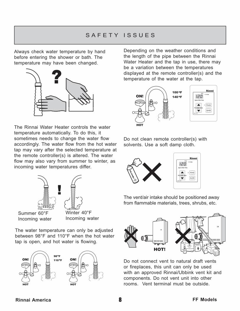
Do not clean remote controller(s) with solvents. Use a soft damp cloth.
The water temperature can only be adjusted between 98°F and 110°F when the hot water tap is open, and hot water is fl owing.
Always check water temperature by hand before entering the shower or bath. The temperature may have been changed.
Depending on the weather conditions and the length of the pipe between the Rinnai Water Heater and the tap in use, there may be a variation between the temperatures displayed at the remote controller(s) and the temperature of the water at the tap.
The Rinnai Water Heater controls the water temperature automatically. To do this, it sometimes needs to change the water fl ow accordingly. The water fl ow from the hot water tap may vary after the selected temperature at the remote controller(s) is altered. The water fl ow may also vary from summer to winter, as incoming water temperatures differ.
The vent/air intake should be positioned away from fl ammable materials, trees, shrubs, etc.
Do not connect vent to natural draft vents or fireplaces, this unit can only be used with an approved Rinnai/Ubbink vent kit and components. Do not vent unit into other rooms. Vent terminal must be outside.
Summer 60°FIncoming water
Winter 40°FIncoming water

HOTHOT
COLDCOLDON!ON!
9Rinnai America FF Models
B A S I C O P E R A T I O N
CHECK WATER TEMPERA-TURE BEFORE ENTERING SHOWER OR BATH.
TEMPERATURE CANNOT BE ADJUST-ED EXCEPT BETWEEN 98 OF AND 110OF WHEN ANY HOT WATER TAP IS OPEN.
To operate the Rinnai Water Heater simply turn any hot water tap on. This will automatically light the burner providing hot water at the preset temperature. If the optional remote controller(s) have been installed, the red “IN USE” indicator will glow on all remote controller(s).
Adjusting Temperature 1
To take control of the Rinnai Water Heater all hot water taps must be closed. Press the "Priority button" on the Controller you want to set the temperature with, and the green "Priority" indicator light will
The outlet water temperature of the Rinnai Water Heater can only be adjusted by the user using the remote controller(s). To adjust the setpoint temperature of the Rinnai Water Heater, all hot water taps must be closed, and all circulating pumps turned off (where applicable). The temperature displayed on this remote controller will also be displayed on all other remote controller(s).
3 Simply press the or button until the required temperature is displayed on the Digital Monitor. There is a hot water scald potential if the thermostat is set to high.
4
2
glow. This indicates that the Rinnai Water Heater is ready to supply hot water at the set temperature as soon as a tap is opened.
Note: Rinnai Water Heater will not provide hot water instantly at the hot water fi xtures. Any cold water existing in the hot water lines must be purged fi rst.
CHECK LOCAL CODESFOR THE MAXIMUMWATER TEMPERATURESETTING ALLOWEDWHEN USED INNURSING HOMES,SCHOOL, DAY CARECENTERS, AND ALLOTHER PUBLICAPPLICATIONS.

10Rinnai America FF Models
A B O U T H O T W A T E R
Hot Water Is Dangerous, especially for the young and the elderly or the infi rm. The Rinnai Water Heater allows you to precisely control the temperature of your hot water, ensuring safe hot water temperatures.
Water Temperatures over 125°F can cause severe burns instantly or death from scalds.
Hot Water can cause fi rst degree burns with exposure for as little as:
3 seconds at 140 °F 20 seconds at 130 °F 8 minutes at 120 °F
Test the temperature of the water with your elbow before placing a child in the bath or shower.
Do not leave a child or an infi rm person in the bath unsupervised.
S c a l d s - F i r s t A i d
1) Remove clothing; Remove all wet clothing, quickly. Wet clothing retains the heat. 2) Apply cold water for 30 minutes; Immediately submerge the burnt area in cold
water for 30 minutes to reduce the heat in the skin, preventing deeper burning. Never use butter, oils or ointment to cover the burn. They may retain the heat.
3) Keep the scalded person warm; Place a blanket around the person.
4) Seek Medical Advice; Call your medical advice hotline and describe the scald, follow their directions.
BURN

11Rinnai America FF Models
GENERAL CONTROLLER INFORMATION
The controller(s) for the Rinnai Water Heater allow the customer to control the functions of the water heater and to diagnose certain fault conditions
REMOTE CONTROLLERS IDENTIFICATION
MC-91-1US (comes with the unit)
MC-100V-1US (optional)
BC-100V-1US (optional)
12Rinnai America FF Models
R E M O T E C O N T R O L L E R O P E R AT I O N
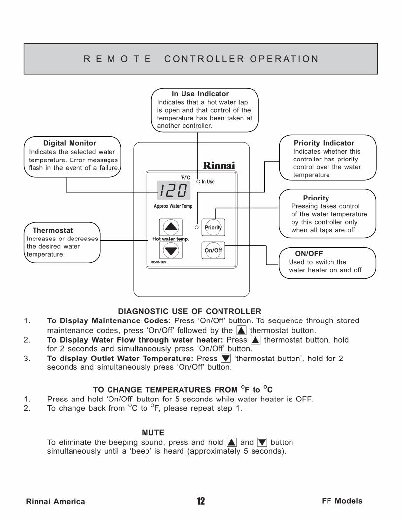
DIAGNOSTIC USE OF CONTROLLER1. To Display Maintenance Codes: Press ‘On/Off’ button. To sequence through stored maintenance codes, press ‘On/Off’ followed by the thermostat button. 2. To Display Water Flow through water heater: Press thermostat button, hold for 2 seconds and simultaneously press ‘On/Off’ button. 3. To display Outlet Water Temperature: Press ‘thermostat button’, hold for 2 seconds and simultaneously press ‘On/Off’ button.
Digital MonitorIndicates the selected watertemperature. Error messagesfl ash in the event of a failure.
ThermostatIncreases or decreases the desired water temperature.
In Use IndicatorIndicates that a hot water tap is open and that control of the temperature has been taken at another controller.
ON/OFF Used to switch the water heater on and off
PriorityPressing takes controlof the water temperatureby this controller only when all taps are off.
Priority Indicator Indicates whether this controller has priority control over the water temperature
MUTE To eliminate the beeping sound, press and hold and button simultaneously until a ‘beep’ is heard (approximately 5 seconds).
TO CHANGE TEMPERATURES FROM OF to OC 1. Press and hold ‘On/Off’ button for 5 seconds while water heater is OFF.2. To change back from OC to OF, please repeat step 1.

With power interruption, water heater will automatically default to the ON position to provide hot water.
Digital MonitorIndicates the selected water temperature. Error messages flash in the event of a failure.
ON/OFFUsed to switch the water heater on and off.
PriorityPressing takes control of the water temperature by this controller only when all taps are open.
FunctionEnables the user to set the clock and sound volume functions.
ThermostatIncreases or decreases the desired water temperature.
In Use IndicatorIndicates that a hot water tap is open and that control of the temperature is taken at another controller.
Water Temperature IndicatorIndicates the selected hot water temperature.
Clock12 Hour AM / PM clock. In the event of a fault, codes for error messages will flash here.
CallAllows user to contact another controller. Can be used as a communication channel for errands or in emergency situations.
In Use IndicatorIndicates that a hot water tap is open and that control of the temperature is taken at another controller.
PriorityPressing takes control of the water temperature by this controller only when all taps are off.
CallAllows user to contact another controller. Can be used as a communication channel for errands or in emergency situations.
Clock12 Hour AM / PM clock. In the event of a fault, codes for error messages will flash here.
ThermostatIncreases or decreases the desired water temperature.
Sound VolumeUsed to select the voice prompt volume.
Water Smart / Bath Fill IndicatorUsed to select Water Smart / Bath Fill Function.
ON/OFFUsed to switch the water heater on and off.
Water Smart / Bath FillUsed to select Water Smart / Bath Fill Function.
Power SaveIndicates that the remote is in the energy saving mode.
Water VolumeUsed to select Water Smart / Bath Fill volumes.
13Rinnai America FF Models
DELUXE CONTROLLER
ABOUT THE DELUXE CONTROLLER (MC-100V-1US)
ABOUT THE THE DELUXE BATHROOM CONTROLLER (BC-100V-1US)
DELUXE BATHROOM CONTROLLER
HOTHOT
COLDCOLDON!ON!
14Rinnai America FF Models
DELUXE CONTROLLER
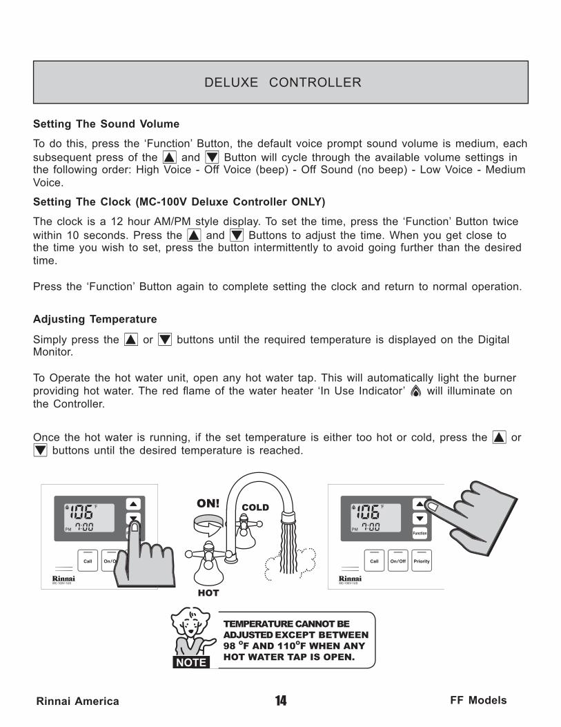
Setting The Clock (MC-100V Deluxe Controller ONLY)
The clock is a 12 hour AM/PM style display. To set the time, press the ‘Function’ Button twice within 10 seconds. Press the and Buttons to adjust the time. When you get close to the time you wish to set, press the button intermittently to avoid going further than the desired time.
Press the ‘Function’ Button again to complete setting the clock and return to normal operation.
Adjusting Temperature
Simply press the or buttons until the required temperature is displayed on the Digital Monitor.
To Operate the hot water unit, open any hot water tap. This will automatically light the burner providing hot water. The red fl ame of the water heater ‘In Use Indicator’ will illuminate on the Controller.
Once the hot water is running, if the set temperature is either too hot or cold, press the or buttons until the desired temperature is reached.
Setting The Sound Volume
To do this, press the ‘Function’ Button, the default voice prompt sound volume is medium, each subsequent press of the and Button will cycle through the available volume settings in the following order: High Voice - Off Voice (beep) - Off Sound (no beep) - Low Voice - Medium Voice.
TEMPERATURE CANNOT BE ADJUSTED EXCEPT BETWEEN 98 OF AND 110OF WHEN ANY HOT WATER TAP IS OPEN.
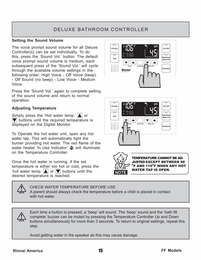
CHECK WATER TEMPERATURE BEFORE USE.A parent should always check the temperature before a child is placed in contactwith hot water.
Each time a button is pressed, a ‘beep’ will sound. The ‘beep’ sound and the ‘bath fill complete’ buzzer can be muted by pressing the Temperature Controller Up and Down buttons simultaneously for more than 3 seconds. To return to original settings, repeat this step.
Avoid getting water in the speaker as this may cause damage.
15Rinnai America FF Models
DELUXE BATHROOM CONTROLLER
Setting the Sound Volume
The voice prompt sound volume for all Deluxe Controller(s) can be set individually. To do this, press the ‘Sound Vol.’ button. The default voice prompt sound volume is medium, each subsequent press of the ‘Sound Vol.’ will cycle through the available volume settings in the following order: High Voice - Off Voice (beep) - Off Sound (no beep) - Low Voice - Medium Voice.
Press the ‘Sound Vol.’ again to complete setting of the sound volume and return to normal operation.
Adjusting Temperature
Simply press the ‘Hot water temp.’ or buttons until the required temperature is
displayed on the Digital Monitor.
To Operate the hot water unit, open any hot water tap. This will automatically light the burner providing hot water. The red fl ame of the water heater ‘In Use Indicator’ will illuminate on the Temperature Controller.
Once the hot water is running, if the set temperature is either too hot or cold, press the ‘hot water temp. or buttons until the desired temperature is reached.
TEMPERATURE CANNOT BE AD-JUSTED EXCEPT BETWEEN 98 OF AND 110OF WHEN ANY HOT WATER TAP IS OPEN.
IT IS THE CUSTOMERS RESPONSIBILITY TO MONITOR THE BATH FILL REMOTE CONTROLLER FUNCTIONS.
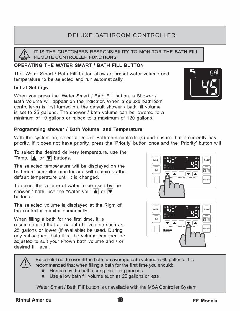
Be careful not to overfi ll the bath, an average bath volume is 60 gallons. It is recommended that when fi lling a bath for the fi rst time you should:= Remain by the bath during the fi lling process.= Use a low bath fi ll volume such as 25 gallons or less.
‘Water Smart / Bath Fill’ button is unavailable with the MSA Controller System.
16Rinnai America FF Models
DELUXE BATHROOM CONTROLLER
OPERATING THE WATER SMART / BATH FILL BUTTON
The ‘Water Smart / Bath Fill’ button allows a preset water volume and temperature to be selected and run automatically.
Initial Settings
When you press the ‘Water Smart / Bath Fill’ button, a Shower / Bath Volume will appear on the indicator. When a deluxe bathroom controller(s) is fi rst turned on, the default shower / bath fi ll volume is set to 25 gallons. The shower / bath volume can be lowered to a minimum of 10 gallons or raised to a maximum of 120 gallons.
Programming shower / Bath Volume and Temperature
With the system on, select a Deluxe Bathroom controller(s) and ensure that it currently has priority, If it does not have priority, press the ‘Priority’ button once and the ‘Priority’ button will
To select the desired delivery temperature, use the ‘Temp.’ or buttons.
The selected temperature will be displayed on the bathroom controller monitor and will remain as the default temperature until it is changed.
To select the volume of water to be used by the shower / bath, use the ‘Water Vol.’ or buttons.
The selected volume is displayed at the Right of the controller monitor numerically.
When fi lling a bath for the fi rst time, it is recommended that a low bath fi ll volume such as 25 gallons or lower (if available) be used. During any subsequent bath fi lls, the volume can then be adjusted to suit your known bath volume and / or desired fi ll level.
HOTHOT
COLDCOLDON!ON!
HOTHOT
COLDON!OFF! COLD
17Rinnai America FF Models
DELUXE BATHROOM CONTROLLER
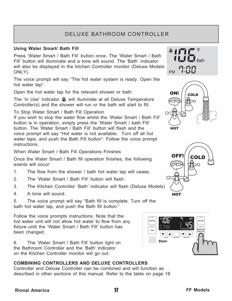
Using Water Smart/ Bath Fill
Press ‘Water Smart / Bath Fill’ button once. The ‘Water Smart / Bath Fill’ button will illuminate and a tone will sound. The ‘Bath’ indicator will also be displayed in the kitchen Controller monitor (Deluxe Models ONLY).
The voice prompt will say “The hot water system is ready. Open the hot water tap”.
Open the hot water tap for the relevant shower or bath.
The ‘In Use’ indicator will illuminate at all Deluxe Temperature Controller(s) and the shower will run or the bath will start to fill.
To Stop Water Smart / Bath Fill OperationIf you wish to stop the water flow whilst the ‘Water Smart / Bath Fill’ button is in operation, simply press the ‘Water Smart / bath Fill’ button. The ‘Water Smart / Bath Fill’ button will flash and the voice prompt will say “Hot water is not available. Turn off all hot water taps, and push the Bath Fill button”. Follow the voice prompt instructions.
When Water Smart / Bath Fill Operations Finishes
Once the Water Smart / Bath fill operation finishes, the following events will occur:
1. The flow from the shower / bath hot water tap will cease.
2. The ‘Water Smart / Bath Fill’ button will flash.
3. The Kitchen Controller ‘Bath’ indicator will flash (Deluxe Models)
4. A tone will sound.
5. The voice prompt will say “Bath fill is complete. Turn off the bath hot water tap, and push the Bath fi ll button.”
Follow the voice prompts instructions. Note that the hot water unit will not allow hot water to fl ow from any fi xture until the ‘Water Smart / Bath Fill’ button has been changed.
6. The ‘Water Smart / Bath Fill’ button light on the Bathroom Controller and the ‘Bath’ indicator on the Kitchen Controller monitor will go out.
COMBINING CONTROLLERS AND DELUXE CONTROLLERSController and Deluxe Controller can be combined and will function asdescribed in other sections of this manual. Refer to the table on page 18
aP teS rellortnoC t )ledoM FF( nret
+++SU1-19-CM1++SU1-19-CM+SU1-19-CM2+SU1-19-CM+SU1-19-CM+SU1-19-CM3
SU1-19-CM +SU1-19-CM+SU1-19-CM+SU1-19-CM4001-CM +V001-CB ++SU1-19-CM5 V
001-CM+V001-CB+SU1-19-CM+SU1-19-CM6 V
t dna”ytiroirP“ eht dloh dna sserp ,rellortnoc htrof eht roF ** snottub "ffO/nO" ehsdnoces 5 yletamixorppa( draeh si ”peeb“ a litnu ylsuoenatlumis .)
etomeR exuleD dna srellortnoC— — —
— ——
—**
ledom
04153103152102151101180160140120100189
581061051041531031521021———
———
—————
REU-V2532FFUREU-V2520FFU
REU-V2520FFUC
REU-V2532FFUC 58106105104153103152102151101180160140120100189A .xorpp
(°C) erutarepmet 58176606754525946434241404938373
erutarepmet
Water Smart / Bath Fill Temperature Table
water smart/bath fill temperature 02181161141121101180160140120100189Approx.temperature (°C) 948474644434241404938373
erutarepmet
18Rinnai America FF Models
CONTROLLERS SET PATTERN/TEMPERATURE TABLES
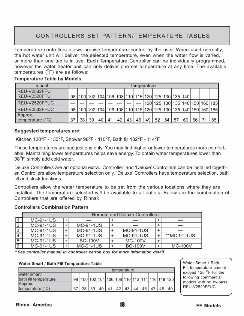
Temperature controllers allows precise temperature control by the user. When used correctly, the hot water unit will deliver the selected temperature, even when the water fl ow is varied, or more than one tap is in use. Each Temperature Controller can be individually programmed, however the water heater unit can only deliver one set temperature at any time. The available temperatures (OF) are as follows:
Suggested temperatures are:
Kitchen 120OF - 130OF, Shower 98OF - 110OF, Bath fi ll 102OF - 114OF
These temperatures are suggestions only. You may fi nd higher or lower temperatures more comfort-able. Maintaining lower temperatures helps save energy. To obtain water temperatures lower than 98OF, simply add cold water.
Deluxe Controllers are an optional extra. ‘Controller’ and ‘Deluxe’ Controllers can be installed togeth-er. Controllers allow temperature selection only. ‘Deluxe’ Controllers have temperature selection, bath fi ll and clock functions.
Controllers allow the water temperature to be set from the various locations where they are installed. The temperature selected will be available to all outlets. Below are the combination of Controllers that are offered by Rinnai:
**See controller manual in controller carton box for more infomation detail.
Water Smart / Bath Fill temperature cannot exceed 120 OF for the following commercial models with no by-pass: REU-V2520FFUC.
Temperature Table by Models
Controllers Combination Pattern
19Rinnai America FF Models
E R R O R M E S S A G E S
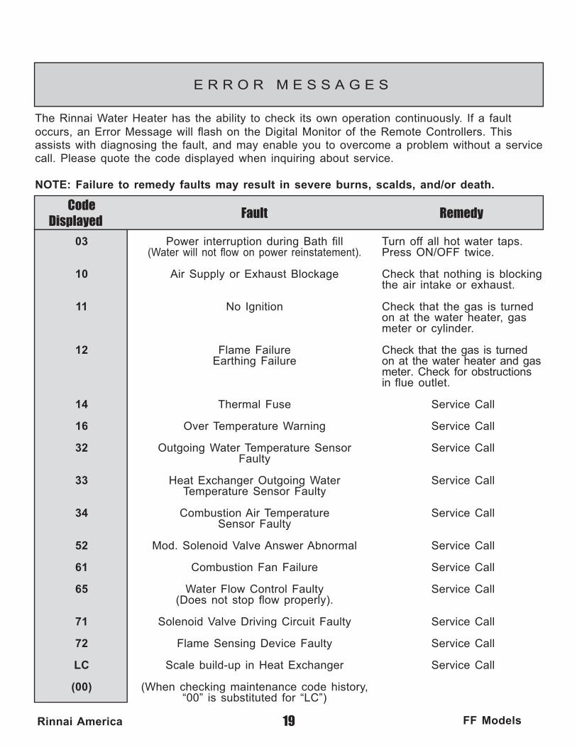
The Rinnai Water Heater has the ability to check its own operation continuously. If a fault occurs, an Error Message will fl ash on the Digital Monitor of the Remote Controllers. This assists with diagnosing the fault, and may enable you to overcome a problem without a service call. Please quote the code displayed when inquiring about service.
NOTE: Failure to remedy faults may result in severe burns, scalds, and/or death.
Code Displayed Fault Remedy
Turn off all hot water taps.Press ON/OFF twice.
Check that nothing is blocking the air intake or exhaust. Check that the gas is turned on at the water heater, gas meter or cylinder.
Check that the gas is turned on at the water heater and gas meter. Check for obstructions in flue outlet.
Service Call
Service Call
Service Call
Service Call
Service Call
Service Call
Service Call
Service Call
Service Call
Service Call
Service Call
03
10
11
12
14
16
32
33
34
52
61
65
71
72
LC
(00)
Power interruption during Bath fi ll(Water will not fl ow on power reinstatement).
Air Supply or Exhaust Blockage
No Ignition
Flame Failure
Earthing Failure
Thermal Fuse
Over Temperature Warning
Outgoing Water Temperature Sensor
Faulty
Heat Exchanger Outgoing WaterTemperature Sensor Faulty
Combustion Air Temperature
Sensor Faulty
Mod. Solenoid Valve Answer Abnormal
Combustion Fan Failure
Water Flow Control Faulty(Does not stop fl ow properly).
Solenoid Valve Driving Circuit Faulty
Flame Sensing Device Faulty
Scale build-up in Heat Exchanger
(When checking maintenance code history,“00” is substituted for “LC”)
20Rinnai America FF Models
M A I N T E N A N C E & S E R V I C E I N F O R M A T I O N
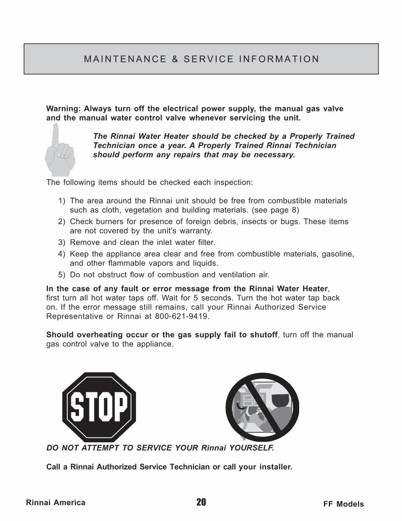
Warning: Always turn off the electrical power supply, the manual gas valve and the manual water control valve whenever servicing the unit.
The Rinnai Water Heater should be checked by a Properly Trained Technician once a year. A Properly Trained Rinnai Technician should perform any repairs that may be necessary.
The following items should be checked each inspection:
1) The area around the Rinnai unit should be free from combustible materials such as cloth, vegetation and building materials. (see page 8)
2) Check burners for presence of foreign debris, insects or bugs. These items are not covered by the unit’s warranty.
3) Remove and clean the inlet water fi lter.
4) Keep the appliance area clear and free from combustible materials, gasoline, and other fl ammable vapors and liquids.
5) Do not obstruct fl ow of combustion and ventilation air.
In the case of any fault or error message from the Rinnai Water Heater, fi rst turn all hot water taps off. Wait for 5 seconds. Turn the hot water tap back on. If the error message still remains, call your Rinnai Authorized Service Representative or Rinnai at 800-621-9419.
Should overheating occur or the gas supply fail to shutoff, turn off the manual gas control valve to the appliance.
DO NOT ATTEMPT TO SERVICE YOUR Rinnai YOURSELF.
Call a Rinnai Authorized Service Technician or call your installer.
21Rinnai America FF Models
M A I N T E N A N C E & S E R V I C E I N F O R M A T I O N
MAINTENANCE SUGGESTIONS
This water heater has been designed and constructed for a long performance life when installed and operated properly under normal conditions. Regular inspections, as outlined in this section, are strongly recommended as a means of keeping your heater operating effi ciently.
1. Cleaning The water heater must be cleaned annually. Keep the water heater clear of dust and debris especially in and around burner. Cleaning procedures for the Rinnai Water Heater are as follows: 1) Turn off and disconnect electrical power. Allow
to cool for one hour. 2) Remove the Front Panel by removing screws.
See parts breakdown on panels. 3) Use pressurized air to remove dust from around
main burner. 4) Use soft dry cloth to wipe cabinet.
DO NOT DAMAGE OR DISTORT ANY PARTS OF HEATER.
DO NOT USE WET CLOTH OR SPRAY CLEANERS ON BURNER.
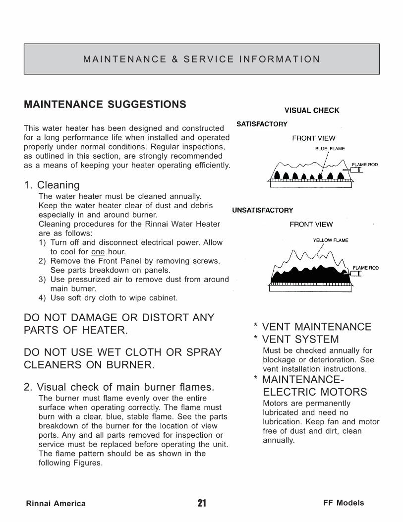
2. Visual check of main burner fl ames. The burner must fl ame evenly over the entire surface when operating correctly. The fl ame must burn with a clear, blue, stable fl ame. See the parts breakdown of the burner for the location of view ports. Any and all parts removed for inspection or service must be replaced before operating the unit.The fl ame pattern should be as shown in the following Figures.
* VENT MAINTENANCE * VENT SYSTEM
Must be checked annually for blockage or deterioration. See vent installation instructions.
* MAINTENANCE-ELECTRIC MOTORS Motors are permanently lubricated and need no lubrication. Keep fan and motor free of dust and dirt, clean annually.

22Rinnai America FF Models
TROUBLE SHOOTING AND COMMON QUESTIONS
Q - I don't have any hot water when I open the tap!
A - Make sure there is gas, water and electricity to the Rinnai Water Heater(the power is turned on and the gas is turned on)
Q - When I was using the hot water, the water got cold!
A - If you adjusted the fl ow from the tap to lessen it, you may have gone below the minimum fl ow required. The Rinnai Water Heater requires a minimum fl ow rate to operate (see specifi cation page for fl ow rate of your unit). If you mix the water with a tap and attempt to get a temperature well below the temperature being controlled by the unit, it may drop the fl ow below the desired minimum fl ow rate. Decrease the temperature supplied by the Rinnai Water Heater at the remote control or increase your total fl ow.
Q - White smoke comes out of the exhaust!
A - During colder weather when the exhaust temperature is hotter than the air, the exhaust fumes condense producing white steam.
Q - When I open a hot tap. I do not immediately get hot water!
A - Hot water must travel through your plumbing from the Rinnai Water Heater to the faucet. The time period for hot water to reach your fi xture is determined by the amount of water in your plumbing system between your water heater and the fi xture, water pressure, fl ow rate of fi xture in use, etc.
Q - After I turn off the hot water tap, the fan on the Rinnai Water Heaters continues to run!
A - The fan is designed to be on for 65 seconds after the fl ow of water stops.This is to ensure constant water temperatures during rapid starting and stopping, as well as exhausting any residual gas fl ue products from the unit.
23Rinnai America FF Models
FOR YOUR SAFETY READ BEFORE OPERATING
Warning: If you do not follow these instructions exactly, a fi re or explosion may result causing property damage, personal injury or loss of life.
A. This appliance does not have a pilot. It is equipped with a direct ignition device which automatically lights the burner. Do not try to light the burner by hand.
B. BEFORE OPERATING: Smell all around the appliance area for gas. Be sure to smell next to the fl oor be cause some gas is heavier than air and will settle on the fl oor.
WHAT TO DO IF YOU SMELL GAS
• Do not try to light any appliance.
• Do not touch any electric switch, do not use any phone in your building.
• Immediately call your gas supplier from a neighbor’s phone. Follow the gas supplier’s instructions.
• If you cannot reach your gas supplier, call the fi re department.
C. Use only your hand to operate remote control keypad. Never use tools. If the remote keypad doesn’t work, do not try to repair it, call a qualifi ed service technician. Force or attempted repair may result in a fi re or explosion.
D. Do not use this appliance if any part has been under water. Immediately call a qualifi ed service technician to inspect the appliance and to replace any part of the control system and any gas control which has been under water.
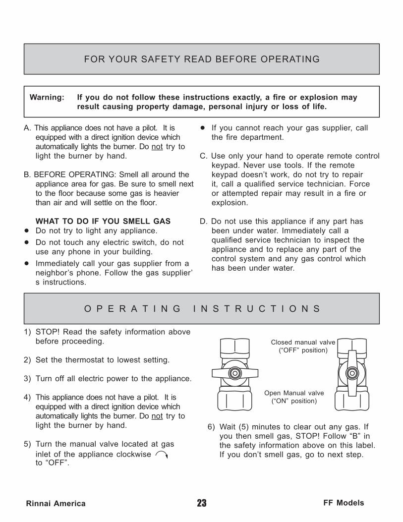
6) Wait (5) minutes to clear out any gas. If you then smell gas, STOP! Follow “B” in the safety information above on this label. If you don’t smell gas, go to next step.
Closed manual valve(“OFF” position)
Open Manual valve(“ON” position)
1) STOP! Read the safety information above before proceeding.
2) Set the thermostat to lowest setting.
3) Turn off all electric power to the appli ance.
4) This appliance does not have a pilot. It is equipped with a direct ignition device which automatically lights the burner. Do not try to light the burner by hand.
5) Turn the manual valve located at gas inlet of the appliance clockwise to “OFF”.
O P E R A T I N G I N S T R U C T I O N S
24Rinnai America FF Models
O P E R A T I N G I N S T R U C T I O N S
7) Turn the manual valve located at the gas inlet of appliance counterclockwis
to “ON”.
8) Turn on all electric power to the appliance.
C A R E & L I M E C O N D I T I O N W A R N I N G
9) Set thermostat to desired setting.
10) If the appliance will not operate, Follow the instructions “To Turn Off Gas To Appliance” and call yourservice technician or gas supplier.
To Turn Off Gas To Appliance
1) Set the thermostat to lowest setting.
2) Turn off all electric power to the appliance if service is to be performed.
3) Turn the manual valve at gas inlet of appliance clockwise to “OFF”
Care of Unit’s Exterior:
Keep the exterior cabinet clean. Use a soft cloth and warm water when cleaning the cabinet. Do Not use volatile substances such as benzene and thinners, as they may ignite, or cause fading of the paint.
Lime Condition Warning Signal:
If you notice “LC” fl ashing on the remote key pad, this means the unit is beginning to lime up, and MUST be fl ushed. Contact a qualifi ed Rinnai service technician to fl ush the appliance. Failure to fl ush the appliance when “LC” is fl ashing, will cause damage to the heat exchanger. Damage caused by lime build up is not covered by the unit’s warranty. To reset the LC Fault Code, turn the power off to the unit. Once power is restored, the LC code will be reset.
25Rinnai America FF Models
Installer’s InstructionsThis section is for the Qualified Installer only. If you are not properly trained, you should not install this unit. The warranty may be voided due to installation by a non-qualifi ed installer. For information on Rinnai Training Courses, call 1-800-621-9419.
www.rinnai.us800-621-9419
Warnings .................................................................. 26,27Locating the Vent Terminal ...................................... 28,29Performance Data ......................................................... 30Dimensions ................................................................... 31Recommended Piping for Installation ............ 32,33,34,35Venting ..................................................................... 36,37Freeze Protection ......................................................... 38Gas Piping Sizing Chart ............................................... 39Gas Piping Notes ......................................................... 40Water Piping Notes ...................................................... 41Pressure Relief Valve ................................................... 41Electrical Connection Notes ......................................... 42Lighting the Unit ........................................................... 43Remote Controllers .................................................. 44,45Testing .......................................................................... 46Schematic Diagram ...................................................... 47
Contentsof Installer’s
Manual

26Rinnai America FF Models
This manual must be followed exactly.
1) Read the safety issues completely before installing the Rinnai Water Heater.
2) This water heater is suitable for residential water (potable) heating ONLY. DO NOT use this water heater for space heating, combination space heating/
domestic water heating, or commercial water heating applications.
3) The Rinnai Water Heater is not suitable for use in pool or spa applications.
4) This unit is designed to be installed indoors using the proper vent piping to exhaust by-products of combustion to the outside environment. Contact your dealer or Rinnai for proper vent kits. DO NOT operate this unit without vent piping connected. Exhaust gasses must be expelled outside the home. All pipe joints shall be taped to help prevent leakage around joints. (Aluminum tape is recommended.)
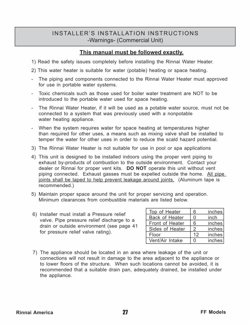
5) Maintain proper space around the unit for proper servicing and operation. Minimum clearances from combustible materials are listed below.
Top of Heater 6 inches Back of Heater 0 inch Front of Heater 6 inches Sides of Heater 2 inches Floor 12 inches Vent/Air Intake 0 inches
6) Installer must install a Pressure relief valve. Pipe pressure relief discharge to a drain or outside environment (see page 41 for pressure relief valve rating).
7) The appliance should be located in an area where leakage of the unit or connections will not result in damage to the area adjacent to the appliance or to lower fl oors of the structure. When such locations cannot be avoided, it is recommended that a suitable drain pan, adequately drained, be installed under the appliance. The pan must not restrict combustion air fl ow.
INSTALLER’S INSTALLATION INSTRUCTIONS-Warnings- (Residential Unit)
27Rinnai America FF Models
This manual must be followed exactly.
1) Read the safety issues completely before installing the Rinnai Water Heater.
2) This water heater is suitable for water (potable) heating or space heating.
- The piping and components connected to the Rinnai Water Heater must approved for use in portable water systems.
- Toxic chemicals such as those used for boiler water treatment are NOT to be introduced to the portable water used for space heating.
- The Rinnai Water Heater, if it will be used as a potable water source, must not be connected to a system that was previously used with a nonpotable water heating appliance.
- When the system requires water for space heating at temperatures higher than required for other uses, a means such as mixing valve shall be installed to temper the water for other uses in order to reduce the scald hazard potential.
3) The Rinnai Water Heater is not suitable for use in pool or spa applications
4) This unit is designed to be installed indoors using the proper vent piping to exhaust by-products of combustion to the outside environment. Contact your dealer or Rinnai for proper vent kits. DO NOT operate this unit without vent piping connected. Exhaust gasses must be expelled outside the home. All pipe joints shall be taped to help prevent leakage around joints. (Aluminum tape is recommended.)
5) Maintain proper space around the unit for proper servicing and operation. Minimum clearances from combustible materials are listed below.
Top of Heater 6 inches Back of Heater 0 inch Front of Heater 6 inches Sides of Heater 2 inches Floor 12 inches Vent/Air Intake 0 inches
INSTALLER’S INSTALLATION INSTRUCTIONS-Warnings- (Commercial Unit)
6) Installer must install a Pressure relief valve. Pipe pressure relief discharge to a drain or outside environment (see page 41 for pressure relief valve rating).
7) The appliance should be located in an area where leakage of the unit or connections will not result in damage to the area adjacent to the appliance or to lower fl oors of the structure. When such locations cannot be avoided, it is recommended that a suitable drain pan, adequately drained, be installed under the appliance.

Maintain 12” of clearance above the highest anticipated snow
level or grade, or w
hichever is greater. Please refer to your local codes for the snow
level in your area.
28Rinnai America FF Models
INSTALLER’S INSTALLATION INSTRUCTIONSLocating the vent terminal
Terminals should be so positioned as to avoid products of
combustion entering openings into buildings or other flues or
vents.
RE
CO
MM
EN
DE
D V
EN
T/A
IR IN
TA
KE
TE
RM
INA
L P
OS
ITIO
N
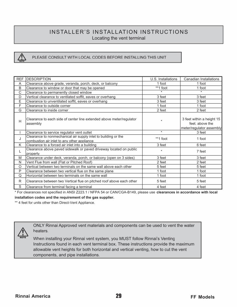
PLEASE CONSULT WITH LOCAL CODES BEFORE INSTALLING THIS UNIT
ONLY Rinnai Approved vent materials and components can be used to vent the water heaters.
When installing your Rinnai vent system, you MUST follow Rinnai’s VentingInstructions found in each vent terminal box. These instructions provide the maximum allowable vent heights for both horizontal and vertical venting, how to cut the vent components, and pipe installations.
snoitallatsnI .S.U NOITPIRCSEDFER snoitallatsnI naidanaC ynoclab ro ,kced ,hcrop ,adnarev ,edarg evoba ecnaraelCA toof 1toof 1
denepo eb yam taht rood ro wodniw ot ecnaraelCB toof 1toof 1**wodniw desolc yltnenamrep ot ecnaraelCC **
teef 3teef 3gnahrevo ro sevae ,tiffos detalitnev ot ecnaraelc lacitreVDteef 3teef 3gnahrevo ro sevae ,tiffos detalitnevnu ot ecnaraelCEtoof 1toof 1renroc edistuo ot ecnaraelCFteef 2teef 2renroc edisni ot ecnaraelCG
Hrotaluger/retem evoba dednetxe enil retnec fo edis hcae ot ecnaraelC
ylbmessa*
51 thgieh a nihtiw teef 3eht evoba .teef
ylbmessa rotaluger/retem*teltuo tnev rotaluger ecivres ot ecnaraelCI teef 3
Jeht ro gnidliub ot telni ylppus ria lacinahcemnon ot ecnaraelC
na ot telni ria noitsubmoc y a rehto pp ecnailtoof 1toof 1**
teef 6teef 3gnidliub a otni telni ria decrof a ot ecnaraelCK
Lcilbup no detacol yawevird devap ro klawedis devap evoba ecnaraelC
p or p tre yteef 7*
teef 3teef 3)sedis 3 no nepo( ynoclab ro ,hcrop ,adnarev ,kced rednu ecnaraelCMteef 2teef 2)fooR dehctiP ro talF( llaw morf eulF tneVNteef 5teef 5rehto hcae evoba llaw emas eht no slanimret owt neewteb lacitreVOtoof 1toof 1enalp emas eht no eulf lacitrev owt neewteb ecnaraelCPtoof 1toof 1llaw emas eht no slanimret owt neewteb latnoziroHQ
teef 5teef 5rehto hcae evoba foor dehctip no eulf lacitreV owt neewteb ecnaraelCR
S teef 4teef 4lanimret a gnicaf lanimret morf ecnaraelC
esu esaelp ,941B-AGC/NAC ro 45 APFN / 1.322Z ISNA ni deificeps ton secnaraelc roF * lacol htiw ecnadrocca ni secnaraelc
.ecnailppA tneV-tceriD naht rehto stinu rof teef 4 **
.reilppus sag eht fo tnemeriuqer eht dna sedoc noitallatsni
29Rinnai America FF Models
INSTALLER’S INSTALLATION INSTRUCTIONSLocating the vent terminal
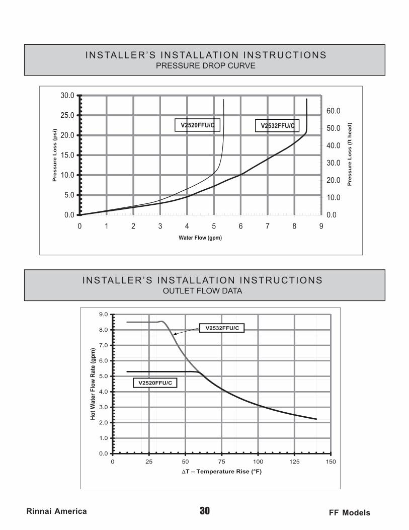
0.0
0.5
0.01
0.51
0.02
0.52
0.03
9876543210)mpg( wolF retaW
Pre
ss
ure
Lo
ss
(p
si)
0.0
0.01
0.02
0.03
0.04
0.05
0.06
Pre
ss
ure
Lo
ss
(ft
he
ad
)V2532FFU/CV2520FFU/C
0.0
0.1
0.2
0.3
0.4
0.5
0.6
0.7
0.8
0.9
0515210015705520
Hot
Wat
er F
low
Rat
e (g
pm)
V2520FFU/C
V2532FFU/C
30Rinnai America FF Models
INSTALLER’S INSTALLATION INSTRUCTIONSPRESSURE DROP CURVE
INSTALLER’S INSTALLATION INSTRUCTIONSOUTLET FLOW DATA
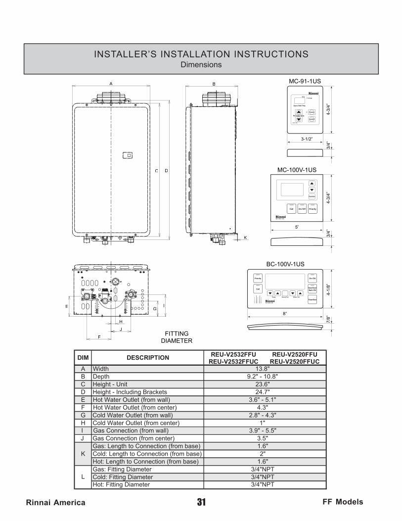
8”
7/8”
4-1/8”
3/4”
5”
4-3/4”
3/4”
3-1/2”
4-3/4”
BC-100V-1US
FITTINGDIAMETER
MC-100V-1US
MC-91-1US
C
BA
G
F
D
IE
H
J
K
DIM DESCRIPTION REU-V2532FFU REU-V2532FFUC
REU-V2520FFU REU-V2520FFUC
A WidthB DepthC Height - UnitD Height - Including BracketsE Hot Water Outlet (from wall)F Hot Water Outlet (from center)G Cold Water Outlet (from wall)H Cold Water Outlet (from center)I Gas Connection (from wall)J Gas Connection (from center)
Gas: Length to Connection (from base)Cold: Length to Connection (from base)Hot: Length to Connection (from base)Gas: Fitting DiameterCold: Fitting DiameterHot: Fitting Diameter
13.8"9.2" - 10.8"
23.6"24.7"
3.6" - 5.1"4.3"
2.8" - 4.3"1"
3.9" - 5.5"3.5"1.6"2"
1.6"3/4"NPT3/4"NPT3/4"NPT
K
L
31Rinnai America FF Models
INSTALLER’S INSTALLATION INSTRUCTIONSDimensions
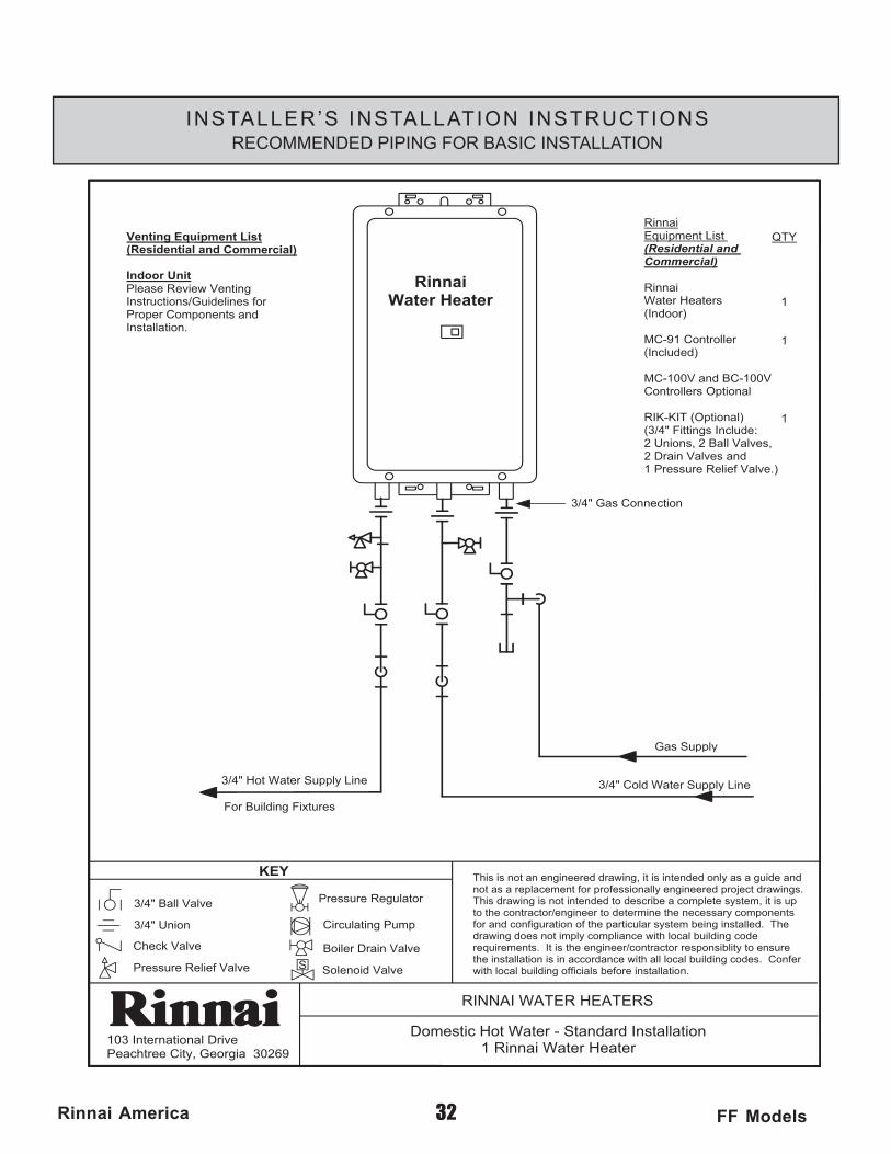
Gas Supply
3/4" Cold Water Supply Line3/4" Hot Water Supply Line
RinnaiWater Heater
RinnaiEquipment List (Residential and Commercial)
RinnaiWater Heaters(Indoor)
MC-91 Controller(Included)
MC-100V and BC-100V Controllers Optional
RIK-KIT (Optional)(3/4" Fittings Include:2 Unions, 2 Ball Valves,2 Drain Valves and 1 Pressure Relief Valve.)
QTY
1
1
1
3/4" Gas Connection
Venting Equipment List
Indoor UnitPlease Review VentingInstructions/Guidelines forProper Components andInstallation.
For Building Fixtures
103 International DrivePeachtree City, Georgia 30269
RINNAI WATER HEATERS
Domestic Hot Water - Standard Installation1 Rinnai Water Heater
This is not an engineered drawing, it is intended only as a guide and not as a replacement for professionally engineered project drawings. This drawing is not intended to describe a complete system, it is up to the contractor/engineer to determine the necessary components for and configuration of the particular system being installed. The drawing does not imply compliance with local building code requirements. It is the engineer/contractor responsiblity to ensure the installation is in accordance with all local building codes. Confer with local building officials before installation.Pressure Relief Valve
3/4" Ball Valve
3/4" Union
Check Valve
S
Pressure Regulator
Circulating Pump
Solenoid Valve
Boiler Drain Valve
KEY
(Residential and Commercial)
32Rinnai America FF Models
INSTALLER’S INSTALLATION INSTRUCTIONSRECOMMENDED PIPING FOR BASIC INSTALLATION
103 International DrivePeachtree City, Georgia 30269
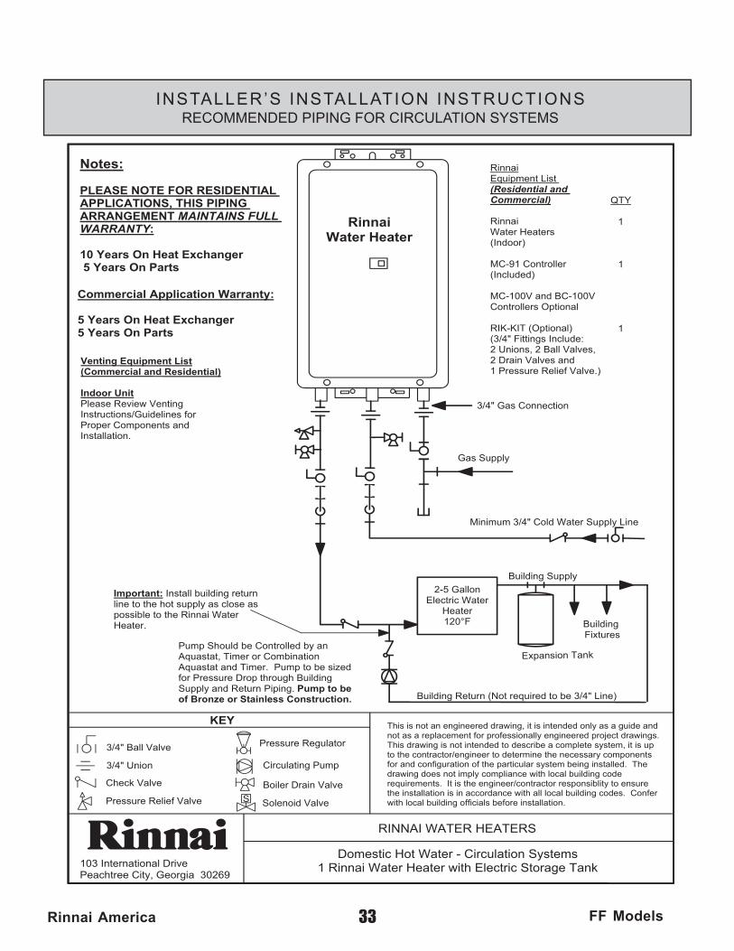
RINNAI WATER HEATERS
Domestic Hot Water - Circulation Systems1 Rinnai Water Heater with Electric Storage Tank
This is not an engineered drawing, it is intended only as a guide and not as a replacement for professionally engineered project drawings. This drawing is not intended to describe a complete system, it is up to the contractor/engineer to determine the necessary components for and configuration of the particular system being installed. The drawing does not imply compliance with local building code requirements. It is the engineer/contractor responsiblity to ensure the installation is in accordance with all local building codes. Confer with local building officials before installation.Pressure Relief Valve
3/4" Ball Valve
3/4" Union
Check Valve
S
Pressure Regulator
Circulating Pump
Solenoid Valve
Boiler Drain Valve
KEY
Minimum 3/4" Cold Water Supply Line
2-5 GallonElectric Water
Heater120°F Building
Fixtures
Building Return (Not required to be 3/4" Line)
Building Supply
Expansion Tank
Gas Supply
QTY
1
1
1
RinnaiWater Heater
Pump Should be Controlled by an Aquastat, Timer or Combination Aquastat and Timer. Pump to be sized for Pressure Drop through Building Supply and Return Piping. Pump to be of Bronze or Stainless Construction.
Notes:
PLEASE NOTE FOR RESIDENTIAL APPLICATIONS, THIS PIPING ARRANGEMENT MAINTAINS FULL WARRANTY:
10 Years On Heat Exchanger 5 Years On Parts
Commercial Application Warranty:
5 Years On Heat Exchanger5 Years On Parts
RinnaiEquipment List (Residential and Commercial)
RinnaiWater Heaters(Indoor)
MC-91 Controller(Included)
MC-100V and BC-100V Controllers Optional
RIK-KIT (Optional)(3/4" Fittings Include:2 Unions, 2 Ball Valves,2 Drain Valves and 1 Pressure Relief Valve.)
3/4" Gas Connection
Important: Install building return line to the hot supply as close as possible to the Rinnai Water Heater.
Venting Equipment List(Commercial and Residential)
Indoor UnitPlease Review VentingInstructions/Guidelines forProper Components andInstallation.
33Rinnai America FF Models
INSTALLER’S INSTALLATION INSTRUCTIONSRECOMMENDED PIPING FOR CIRCULATION SYSTEMS
103 International DrivePeachtree City, Georgia 30269
RINNAI WATER HEATERS
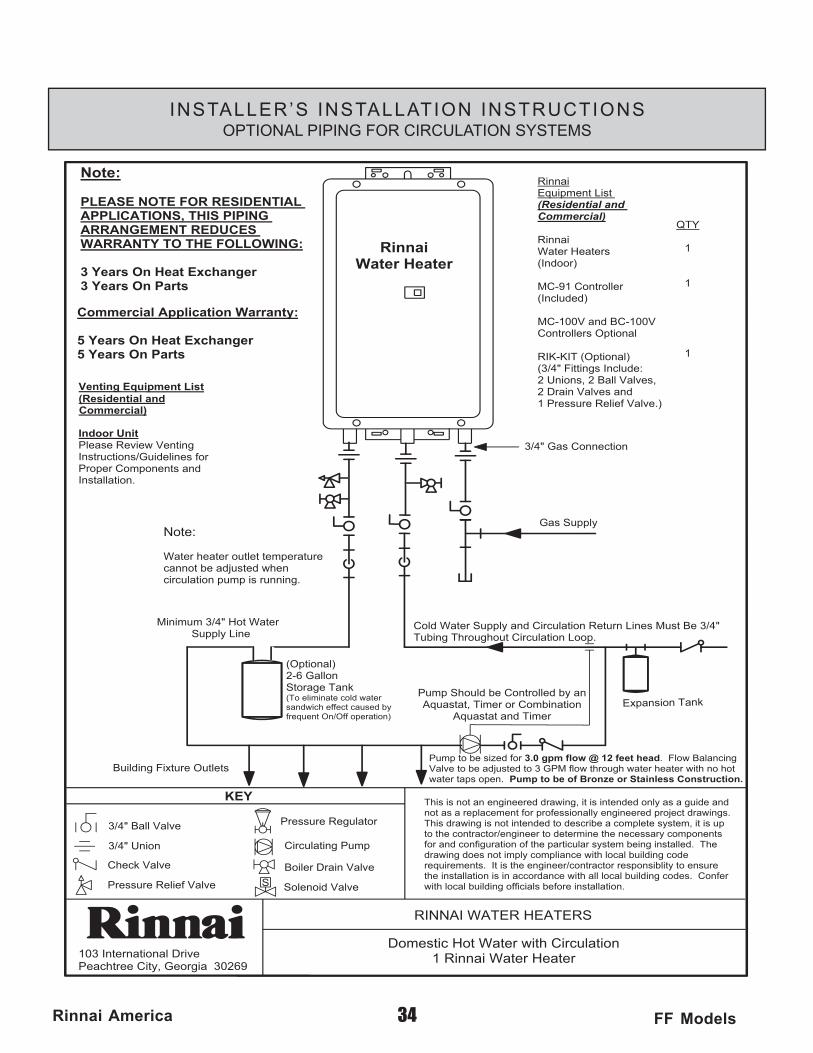
Domestic Hot Water with Circulation1 Rinnai Water Heater
This is not an engineered drawing, it is intended only as a guide and not as a replacement for professionally engineered project drawings. This drawing is not intended to describe a complete system, it is up to the contractor/engineer to determine the necessary components for and configuration of the particular system being installed. The drawing does not imply compliance with local building code requirements. It is the engineer/contractor responsiblity to ensure the installation is in accordance with all local building codes. Confer with local building officials before installation.Pressure Relief Valve
3/4" Ball Valve
3/4" Union
Check Valve
S
Pressure Regulator
Circulating Pump
Solenoid Valve
Boiler Drain Valve
KEY
Minimum 3/4" Hot Water Supply Line
Building Fixture Outlets
(Optional)2-6 GallonStorage Tank(To eliminate cold watersandwich effect caused by frequent On/Off operation)
Pump Should be Controlled by an Aquastat, Timer or Combination
Aquastat and Timer
Pump to be sized for 3.0 gpm flow @ 12 feet head. Flow Balancing Valve to be adjusted to 3 GPM flow through water heater with no hot water taps open. Pump to be of Bronze or Stainless Construction.
Cold Water Supply and Circulation Return Lines Must Be 3/4" Tubing Throughout Circulation Loop.
Note:
Water heater outlet temperature cannot be adjusted when circulation pump is running.
QTY
1
1
1
Expansion Tank
RinnaiWater Heater
Note:
PLEASE NOTE FOR RESIDENTIAL APPLICATIONS, THIS PIPING ARRANGEMENT REDUCES WARRANTY TO THE FOLLOWING:
3 Years On Heat Exchanger3 Years On Parts
RinnaiEquipment List (Residential and Commercial)
RinnaiWater Heaters(Indoor)
MC-91 Controller(Included)
MC-100V and BC-100V Controllers Optional
RIK-KIT (Optional)(3/4" Fittings Include:2 Unions, 2 Ball Valves,2 Drain Valves and 1 Pressure Relief Valve.)
3/4" Gas Connection
Commercial Application Warranty:
5 Years On Heat Exchanger5 Years On Parts
Gas Supply
Venting Equipment List(Residential and
Indoor UnitPlease Review VentingInstructions/Guidelines forProper Components andInstallation.
Commercial)
34Rinnai America FF Models
INSTALLER’S INSTALLATION INSTRUCTIONSOPTIONAL PIPING FOR CIRCULATION SYSTEMS
RinnaiWater Heater
103 International DrivePeachtree City, Georgia 30269
RINNAI WATER HEATERS
Domestic Hot Water - Scale Flush Procedure1 Rinnai Water Heater
This is not an engineered drawing, it is intended only as a guide and not as a replacement for professionally engineered project drawings. This drawing is not intended to describe a complete system, it is up to the contractor/engineer to determine the necessary components for and configuration of the particular system being installed. The drawing does not imply compliance with local building code requirements. It is the engineer/contractor responsiblity to ensure the installation is in accordance with all local building codes. Confer with local building officials before installation.Pressure Relief Valve
3/4" Ball Valve
3/4" Union
Check Valve
S
Pressure Regulator
Circulating Pump
Solenoid Valve
Boiler Drain Valve
KEY
Gas Supply
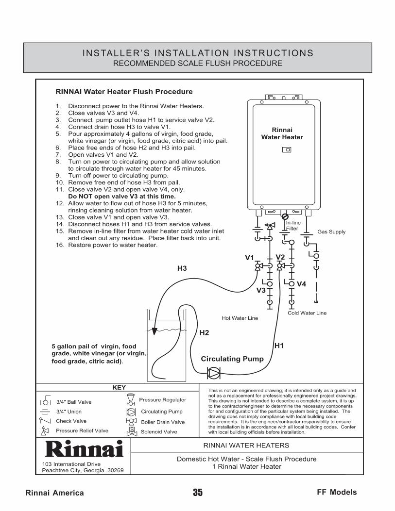
RINNAI Water Heater Flush Procedure
1. Disconnect power to the Rinnai Water Heaters.2. Close valves V3 and V4.3. Connect pump outlet hose H1 to service valve V2.4. Connect drain hose H3 to valve V1.5. Pour approximately 4 gallons of virgin, food grade, white vinegar (or virgin, food grade, citric acid) into pail.6. Place free ends of hose H2 and H3 into pail.7. Open valves V1 and V2.8. Turn on power to circulating pump and allow solution to circulate through water heater for 45 minutes.9. Turn off power to circulating pump.10. Remove free end of hose H3 from pail.11. Close valve V2 and open valve V4, only.
Do NOT open valve V3 at this time.12. Allow water to flow out of hose H3 for 5 minutes, rinsing cleaning solution from water heater.13. Close valve V1 and open valve V3.14. Disconnect hoses H1 and H3 from service valves.15. Remove in-line filter from water heater cold water inlet and clean out any residue. Place filter back into unit.16. Restore power to water heater.
V1
V3
V2
V4
H1
H2
H3
Circulating Pump
5 gallon pail of virgin, food grade, white vinegar (or virgin, food grade, citric acid).
Cold Water LineHot Water Line
n-lineFilterI
35Rinnai America FF Models
INSTALLER’S INSTALLATION INSTRUCTIONSRECOMMENDED SCALE FLUSH PROCEDURE
36Rinnai America FF Models
INSTALLER’S INSTALLATION INSTRUCTIONSVenting
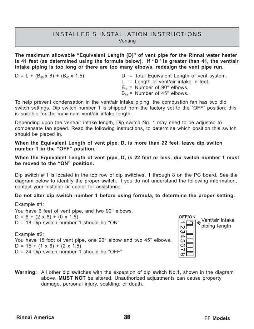
The maximum allowable “Equivalent Length (D)” of vent pipe for the Rinnai water heater is 41 feet (as determined using the formula below). If “D” is greater than 41, the vent/air intake piping is too long or there are too many elbows, redesign the vent pipe run.
D = L + (B90 x 6) + (B45 x 1.5) D = Total Equivalent Length of vent system. L = Length of vent/air intake in feet. B90 = Number of 90° elbows. B45 = Number of 45° elbows.
To help prevent condensation in the vent/air intake piping, the combustion fan has two dip switch settings. Dip switch number 1 is shipped from the factory set to the “OFF” position; this is suitable for the maximum vent/air intake length.
Depending upon the vent/air intake length, Dip switch No. 1 may need to be adjusted to compensate fan speed. Read the following instructions, to determine which position this switch should be placed in.
When the Equivalent Length of vent pipe, D, is more than 22 feet, leave dip switch number 1 in the “OFF” position.
When the Equivalent Length of vent pipe, D, is 22 feet or less, dip switch number 1 must be moved to the “ON” position.
Dip switch # 1 is located in the top row of dip switches, 1 through 8 on the PC board. See the diagram below to identify the proper switch. If you do not understand the following information, contact your installer or dealer for assistance.
Do not alter dip switch number 1 before using formula, to determine the proper setting.
Example #1:
Vent/air intakepiping length
You have 6 feet of vent pipe, and two 90° elbows.D = 6 + (2 x 6) + (0 x 1.5)D = 18 Dip switch number 1 should be “ON”
Example #2: You have 15 foot of vent pipe, one 90° elbow and two 45° elbows. D = 15 + (1 x 6) + (2 x 1.5) D = 24 Dip switch number 1 should be “OFF”
Warning: All other dip switches with the exception of dip switch No.1, shown in the diagram above, MUST NOT be altered. Unauthorized adjustments can cause property damage, personal injury, scalding, or death.
Horizontal Direct
Horizontal Extension
Vertical Direct
37Rinnai America FF Models
INSTALLER’S INSTALLATION INSTRUCTIONSVenting
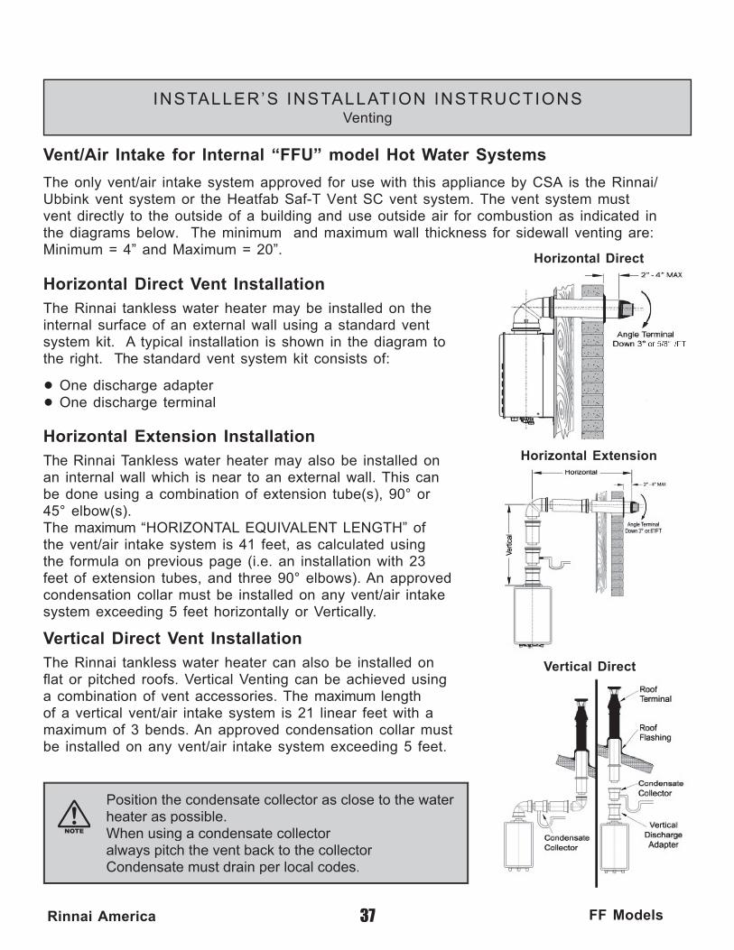
Vent/Air Intake for Internal “FFU” model Hot Water Systems
The only vent/air intake system approved for use with this appliance by CSA is the Rinnai/Ubbink vent system or the Heatfab Saf-T Vent SC vent system. The vent system must vent directly to the outside of a building and use outside air for combustion as indicated in the diagrams below. The minimum and maximum wall thickness for sidewall venting are: Minimum = 4” and Maximum = 20”.
Horizontal Direct Vent InstallationThe Rinnai tankless water heater may be installed on the internal surface of an external wall using a standard vent system kit. A typical installation is shown in the diagram to the right. The standard vent system kit consists of:
• One discharge adapter
• One discharge terminal
Horizontal Extension InstallationThe Rinnai Tankless water heater may also be installed on an internal wall which is near to an external wall. This can be done using a combination of extension tube(s), 90° or 45° elbow(s). The maximum “HORIZONTAL EQUIVALENT LENGTH” of the vent/air intake system is 41 feet, as calculated using the formula on previous page (i.e. an installation with 23 feet of extension tubes, and three 90° elbows). An approved condensation collar must be installed on any vent/air intake system exceeding 5 feet horizontally or Vertically.
Vertical Direct Vent InstallationThe Rinnai tankless water heater can also be installed on fl at or pitched roofs. Vertical Venting can be achieved using a combination of vent accessories. The maximum length of a vertical vent/air intake system is 21 linear feet with a maximum of 3 bends. An approved condensation collar must be installed on any vent/air intake system exceeding 5 feet.
Position the condensate collector as close to the waterheater as possible. When using a condensate collector always pitch the vent back to the collectorCondensate must drain per local codes.
Rinnai is continually updating and improving products, therefore, specifi cations are subject to change without prior notice. Local, state, provincial and federal codes must be adhered to prior to installation.
Climate conditions can dictate special applications. Please refer to local codes before installing product.
Filter
Drain
GasValve
GasColdHot
Turn Water Off
Turn Gas Off
Drain WaterValveWater
38Rinnai America FF Models
INSTALLER’S INSTALLATION INSTRUCTIONSFreeze Protection
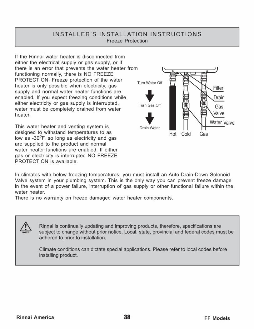
If the Rinnai water heater is disconnected fromeither the electrical supply or gas supply, or ifthere is an error that prevents the water heater fromfunctioning normally, there is NO FREEZEPROTECTION. Freeze protection of the waterheater is only possible when electricity, gassupply and normal water heater functions areenabled. If you expect freezing conditions whileeither electricity or gas supply is interrupted, water must be completely drained from waterheater.
This water heater and venting system isdesigned to withstand temperatures to as low as -30OF, so long as electricity and gasare supplied to the product and normal water heater functions are enabled. If eithergas or electricity is interrupted NO FREEZEPROTECTION is available.
In climates with below freezing temperatures, you must install an Auto-Drain-Down Solenoid Valve system in your plumbing system. This is the only way you can prevent freeze damage in the event of a power failure, interruption of gas supply or other functional failure within the water heater. There is no warranty on freeze damaged water heater components.

39Rinnai America FF Models
INSTALLER’S INSTALLATION INSTRUCTIONSGas Piping Sizing Chart
Capacity Table for Natural Gascubic feet / hour
(table assumes .3 inch pressure drop, specifi c gravity of .60)Nominal Length of Pipe in FeetIron PipeSizeInches 10 20 30 40 50 60 70 80 90 100 125 150 175 2003/4 278 190 152 130 115 105 96 90 84 79 72 64 59 551 520 350 285 245 215 195 180 170 160 150 130 120 110 1001-1/4 1050 730 590 500 440 400 370 350 320 305 275 250 225 2101-1/2 1600 1100 890 760 670 610 560 530 490 460 410 380 350 320
After determining the length of pipe required select the pipe size that will supply the cubic feet per hour of gas required for the input rating of the Rinnai Water Heaters.The formula for fi guring the cubic feet per hour required is:
Gas Input of Rinnai water heater (BTU/HR) CFH = Heating Value of Gas(BTU/FT3)
*Gas input requirement is on the water heater data plate *The heating value of the gas can be obtained from the local Natural Gas Utility
Capacity Table for LP Gas BTUH of undiluted liquifi ed petroleum gases
(table assumes 11 inches of water column pressure at the inlet, .5 inch drop)
Nominal Length of Pipe in FeetIron PipeSizeInches 10 20 30 40 50 60 70 80 90 100 125 1501/2 275 189 152 1293/4 567 393 315 267 237 217 196 185 173 162 1461 1071 732 590 504 448 409 378 346 322 307 275 2521-1/4 2205 1496 1212 1039 913 834 771 724 677 630 567 511

40Rinnai America FF Models
INSTALLER’S INSTALLATION INSTRUCTIONSGas Piping Notes
1) A manual gas control valve must be placed upon the gas supply line to the Rinnai Water Heater. A union can be used on the connection above the shut off valve for the future servicing or disconnection of the unit.
2) Check the type of gas and the gas inlet pressure before connecting the Rinnai Water Heater if the Rinnai Water Heater is not of the gas type that the building is supplied with, DO NOT connect the water heater. Contact the dealer for the proper unit to match the gas type.
3) Minimum and Maximum Gas pressures are listed below: * Minimum value is for input adjustment
Natural Gas: Minimum 6" WC Propane Gas: Minimum 10"WC Maximum 10.5" WC Maximum 13.5" WC
WARNING: Conversion of this unit from natural gas to propane or propane to natural gas CANNOT be done in the fi eld.
4) After completion of gas pipe connections, all joints including the heater must be checked for gas-tightness by means of leak detector solution, soap and water, or an equivalent nonfl ammable solution, as applicable. Caution: Since some leak test solutions, including soap and water, may cause corrosion or stress cracking, the piping must be rinsed with water after testing, unless it has been determined that the leak solution is non-corrosive.
5) The Rinnai Water Heater must be leak tested before it is placed into operation.
6) The Rinnai Water Heater and its individual shut-off valve must be disconnected from the gas supply piping system when pressure testing of the gas supply piping system at test pressures greater than 1/2 psi (3.5 kPa).
7) Always use approved connectors to connect the unit to the gas line. Always purge the gas line of any debris before connection to the water heater.
8) The Rinnai Water Heater must be isolated from the gas supply piping system by closing it's individual manual shutoff valve during any pressure testing of the gas supply piping system at test pressures equal to or less than 1/2 psi (3.5 kPa).
9) The Rinnai Water Heater Installation location must provide adequate Combustion and Ventilation airfl ow.
41Rinnai America FF Models
INSTALLER’S INSTALLATION INSTRUCTIONSWater Piping Notes
1) A manual water control valve must be placed upon the water inlet connection to the Rinnai Water Heater before it is connected to the water line. Unions may be used on both the hot/cold water supply lines, for the future servicing or disconnection of the unit.
2) All soldering materials and piping must be compatible with potable water.
3) Purge the water line to remove from it all debris and air. Debris will damage the Rinnai Water Heaters.
4) There is a wire mesh strainer on the Rinnai Water Heater’s inlet to discourage the introduction of debris to the unit. It will need to be cleaned periodically. DO NOT operate unit without fi lter in place. Clean this fi lter before leaving the job site.
5) It is recommended that auto drain down solenoids are installed in all applications below freezing.
WARNING: DO NOT reverse the inlet and outlet (cold and hot water) connections on the unit. This would cause the Rinnai Water Heater to operate dangerously or not at all.
INSTALLER’S INSTALLATION INSTRUCTIONSPressure Relief Valve
1) ANSI code calls for the addition of an approved pressure relief valve to all water heating systems.
2) The pressure relief valve must meet the following criteria: The relief valve must comply with the standard for Relief Valves and Automatic Gas Shutoff Devices for Hot Water Supply Systems ANSI Z21. 22 and/or the standard CAN1-4.4 Temperature, Pressure, Temperature and Pressure Relief Valves and Vacuum Relief Valves. This relief valve must be rated up to 150 PSI of pressure.
3) The relief valve should be added to the hot water outlet line per manufacturer's instructions. DO NOT place any other type valve or shut off device between the relief valve and the hot water heater.
4) The discharge from the pressure relief valve should be piped to the ground or into a drain system to prevent exposure or possible burn hazards to humans or other plant or animal life. Water discharged from the relief valve could cause severe burns instantly, scalds and/or death.
5) Do not plug the relief valve and do not install any reducing fi ttings or other restrictions in the relief line. The relief line should allow for complete drainage of the valve and the line.
6) If a relief valve discharges periodically, this may be due to thermal expansion in a closed water supply system. Contact the water supplier or local plumbing inspector on how to correct this situation. Do not plug the relief valve.
7) Pressure relief valve must be manually operated once a year to check for correct operation. Caution: See Item 4 before manually operating relief valve.
8) Should overheating occur or the gas supply fail to shut off, turn off the manual gas valve on the Rinnai.
PCB
GROUND ON
OFFTERMINAL
DISCONNECTSWITCH
120VAC CONNECTION WIRES (Black-Hot/White-Neutral)
42Rinnai America FF Models
INSTALLER’S INSTALLATION INSTRUCTIONSElectrical Connection Notes
WARNING: The Rinnai Water Heaters must be electrically grounded in accordance with local codes or in the absence of local codes with the most recent edition of the National Electrical Code, ANSl/NFPA 70. In Canada, all electrical wiring to the Rinnai Water Heaters should be in accordance with local codes and the Canadian Electrical Code, CSA C22.1 Part 1. Do not rely on the gas or water piping to ground the metal parts of the water heater.
CAUTION: Label all wires prior to disconnection when servicing controls. Wiring errors can cause improper and dangerous operation. Verify proper operation after servicing.
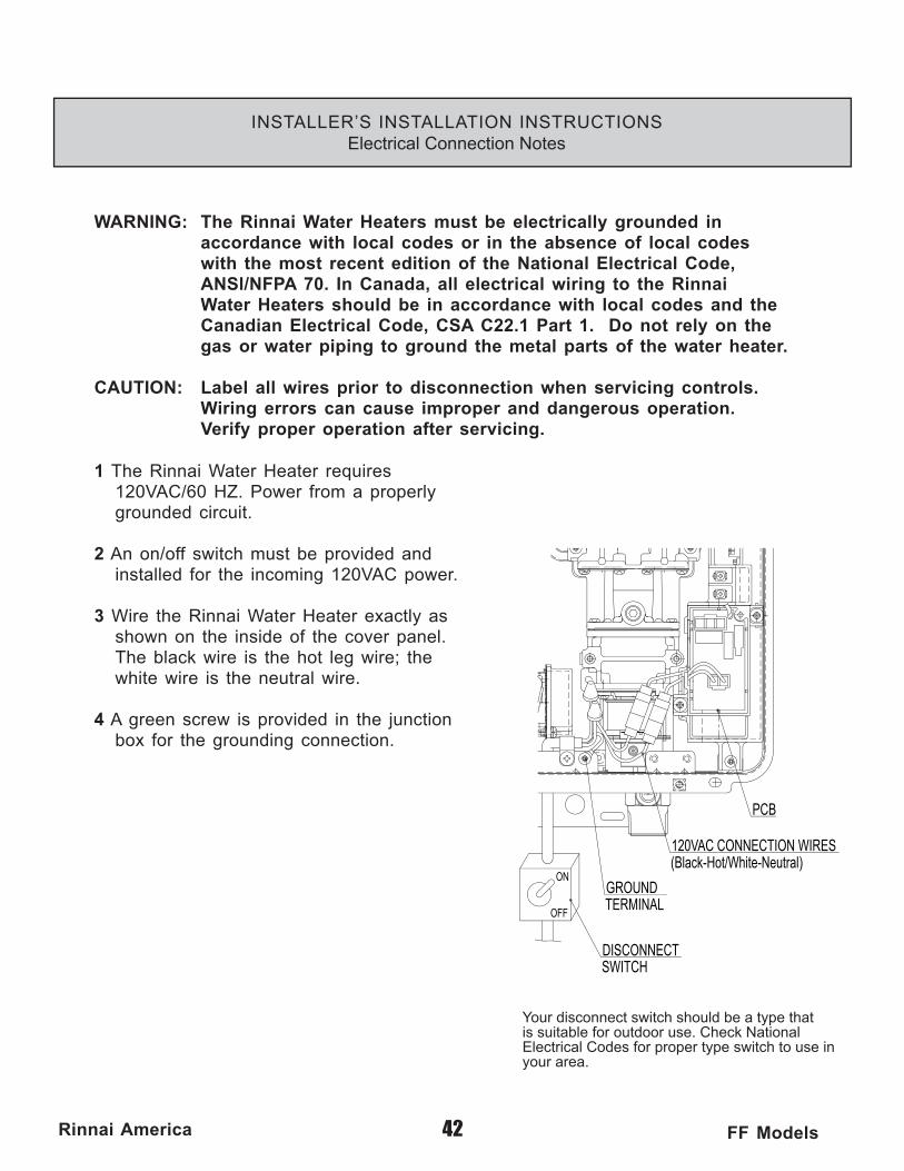
1 The Rinnai Water Heater requires 120VAC/60 HZ. Power from a properly grounded circuit.
2 An on/off switch must be provided and installed for the incoming 120VAC power.
3 Wire the Rinnai Water Heater exactly as shown on the inside of the cover panel. The black wire is the hot leg wire; the white wire is the neutral wire.
4 A green screw is provided in the junction box for the grounding connection.
Your disconnect switch should be a type that is suitable for outdoor use. Check National Electrical Codes for proper type switch to use in your area.
43Rinnai America FF Models
INSTALLER’S INSTALLATION INSTRUCTIONSLighting the Unit
WARNING: If you do not follow these instructions exactly, a fi re or explosion may result causing property damage, personal injury or loss of life.
1) This water heater does not have a pilot. It is equipped with a direct ignition device which automatically lights the burner. DO NOT TRY TO LIGHT THE BURNER BY HAND.
2) Before operating the Rinnai Water Heater smell all around the unit for gas. Be sure to smell near the ground as leaking gas may settle there.
3) Turn the manual gas control valve on.
STOP!! READ THE SAFETY ISSUES ON PAGES 8
4) Turn on any hot water tap. The Rinnai Water Heater should light and begin heating your water.
If the Rinnai Water Heater fails to light
1) DO NOT ATTEMPT TO LIGHT BY HAND.
2) Turn off the electrical power to the unit.
3) Turn off the manual gas control.
4) Wait 5 minutes, if you smell gas, go to a neighbor's house and call the gas company or the fi re department. If you do not smell gas, go to the next step.
5) Turn the manual gas control valve on.
6) Turn the electrical power to the unit on.
7) Turn on any hot water tap.
8) If the unit still fails to light, turn off the electricity and gas to the unit and call Rinnai 1-800-621-9419.

When the Temperature Controller(s) is used in public applications, it should be installed where it can not be adjusted by the public (i.e. a maintenance room or manager’s offi ce).
The Temperature Controller(s) have default temperature settings for The Rinnai Water Heater models. See page 18 for details.
44Rinnai America FF Models
INSTALLER’S INSTALLATION INSTRUCTIONSRemote Controllers- General
The remote controls for the Rinnai Water Heater allow the customer to control the functions of the water heater and to diagnose certain fault conditions.
Before installing the remote controllers, determine the most convenient location(s). When deciding on the best location for the remote controllers, please consider the following items:
1) Place the controllers out of reach of small children.
2) Avoid locations where remote controller(s) will become hot. (over the stove, near the oven or a radiant heater.
3) Avoid direct sunlight. (The digital monitor can be diffi cult to read in direct sunlight)
4) Avoid areas where remote controller(s) can be splashed with cooking water, oil or sauce.
5) Remote controller(s) cables carry low voltage, 12VDC digital.
Remote controller(s) can be wired in series or in parallel depending on the distance from the Rinnai Water Heaters to the controllers.
Every installation is different
Rinnai
Main ControllerMain Controller
Bath Controller
Bath Controller
Rinnai
Series Parallel

1-11/32”
3-5/16”
45Rinnai America FF Models
INSTALLER’S INSTALLATION INSTRUCTIONSRemote Controllers - Installation
1) Determine a suitable location for the controller.
2) Make three holes on the wall as shown.
3) Run the cable between the controller and the Rinnai Water Heater or the controller and the other controller.
4) Remove the face plate from the remote controller(s), using a screw driver.
5) Connect the cable to the remote controller(s).
6) Mount the controller to the wall using the holes drilled in step 2.
Note: If the cable cannot be run in the wall cavity, the plastic knockout should be removed from the top or bottom of the controller to allow fl ush mounting with the wall
7) Disconnect the power from the Rinnai Water Heater.
8) Remove the cover of the Rinnai Water Heater.
9) Remove the plastic cover from the PCB and electrical connections.
DO NOT ATTEMPT TO CONNECT THE REMOTE CONTROLLERS WITH THE POWER ON, THERE'S 120 VOLT POTENTIAL, NEXT TO THE REMOTE CONTROLLER CONNECTIONS INSIDE THE UNIT. All service and wiring should be performed by a certifi ed installer.
10) Thread the cable through the access hole at the base of the unit and connect the wires to the controller terminals on the right hand side bottom of the PCB.
11) Secure the controller cable using the clamp provided.
12) Replace plastic cover over PCB and then replace the cover of the Rinnai Water Heaters.

Model # Inlet Gas Pressure Manifold Forced Low Fire Manifold Forced High FireREU1616-W Series 6" - 10.5" 0.73" 3.5"REU2020-W Series 6" - 10.5" 0.74" 3.7"REU2526-W Series 6" - 10.5" 0.56" 3.4"REU2532-W Series 6" - 10.5" 0.56" 3.4"
Model # Inlet Gas Pressure Manifold Forced Low Fire Manifold Forced High FireREU1616-W Series 10" - 13.5" 0.72" 3.3"REU2020-W Series 10" - 13.5" 0.74" 3.7"REU2526-W Series 10" - 13.5" 0.88" 5.1"REU2532-W Series 10" - 13.5" 0.88" 5.1"
REU2520FFU Series 6" - 10.5" 0.77" 3.7"REU2532FFU Series 6" - 10.5" 0.77" 3.7"
REU2520FFU Series 10" - 13.5" 0.93" 4.2"REU2532FFU Series 10" - 13.5" 0.93" 4.2"
Propane Gas Inlet and Manifold Gas Pressure by Model
Natural Gas Inlet and Manifold Gas Pressure by Model
Propane Gas Inlet and Manifold Gas Pressure by Model
Natural Gas Inlet and Manifold Gas Pressure by Model
46Rinnai America FF Models
INSTALLER’S INSTALLATION INSTRUCTIONSTesting
1) Turn on the gas and water.
2) Check for water and gas leaks. Use soapy water to test for gas leaks.
3) Remove pressure test point screw, attach pressure gauge to test point.
4) Turn Power on.
5) Open any hot water tap fully.
6) Check test point or supply pressure in water columns per inch.
NOTE: The pressure may be low due to too little fl ow, too high an incoming temperature, and/or undersized gas piping. Examine these areas before determining that the pressure needs to be adjusted. Contact Rinnai before adjusting manifold pressures at 1-800-621-9419. Failure to contact Rinnai, could void unit’s warranty.
7) If it is determined that the gas pressure needs adjusting, fi rst check the in coming pressure at the test point on the gas inlet. If it is correct follow the adjusting procedure contained in the pouch of the unit EXACTLY.
The regulator is pre-set at the factory, it should not need resetting.
8) Turn the hot water off. Turn the power off. Remove the pressure guage and replace the test point screw. Check for a gas leak around the test point screw.
9) Replace the front cover.
10) Turn the power back on.
11) Check the operation of the unit. Check the operation of each of the remote controller(s). Check the operation of the Power failure protection system.
12) Explain the proper operation of the Rinnai Water Heaters to the customer.
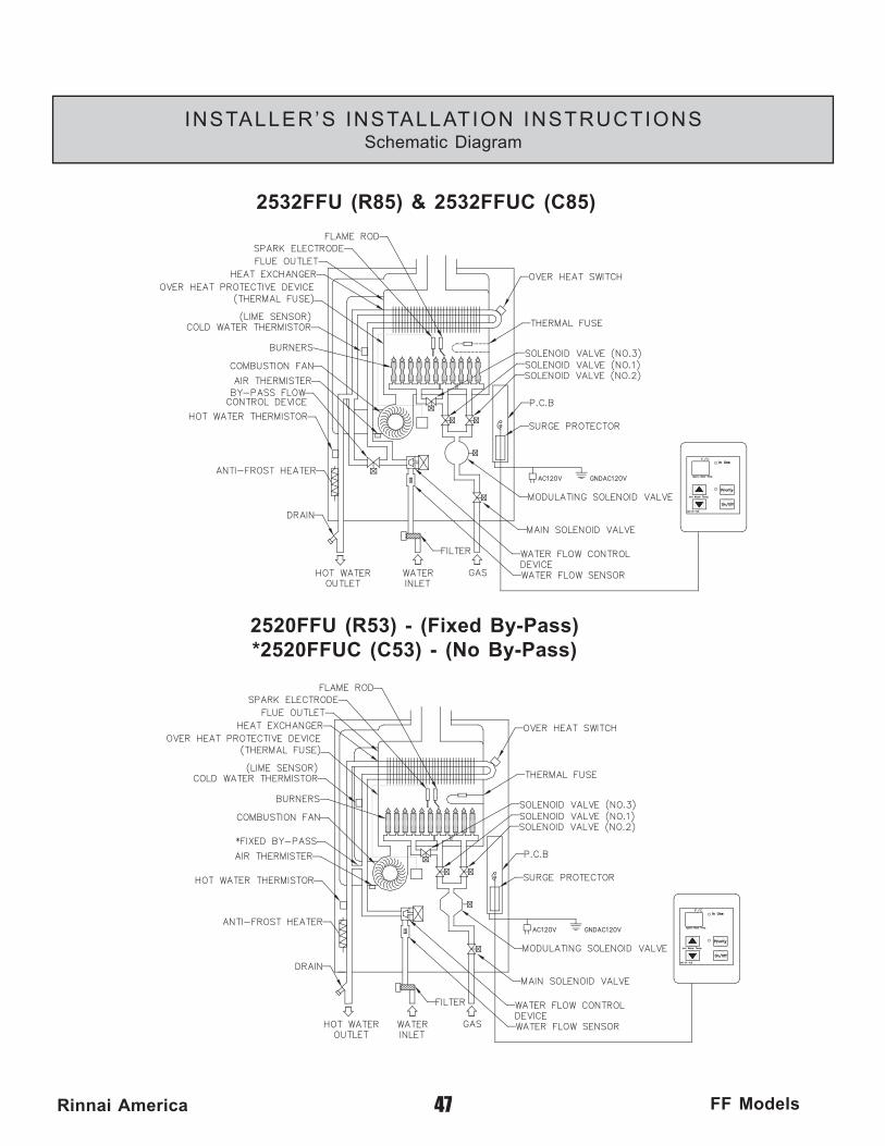
47Rinnai America FF Models
INSTALLER’S INSTALLATION INSTRUCTIONSSchematic Diagram
2532FFU (R85) & 2532FFUC (C85)
2520FFU (R53) - (Fixed By-Pass)*2520FFUC (C53) - (No By-Pass)
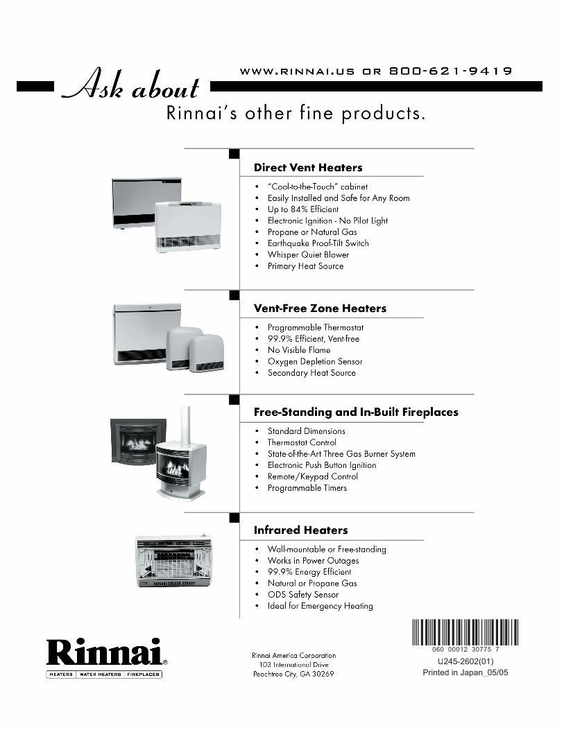
060 00012 30775 7
U245-2602(01)Printed in Japan_05/05