operation & maintenance manual type gis 36 kv cubicle · 2019-04-15 · 3.1. - cubicle...
TRANSCRIPT

OPERATION & MAINTENANCE MANUAL TYPE GIS 36 kV CUBICLE
INTRODUCTION
SPECIFICATIONSSTANDARDS & OPERATING CONDITIONSTECHNICAL DATANORMAL SERVICE CONDITIONS FOR INDOOR
STRUCTURAL DETAILS & GENERAL ARRANGEMENTCUBICLE STRUCTURETYPICAL ARRANGEMENTSF6 GAS SYSTEMPRESSURE RELIEF DISC
HANDLING & STORAGEPRECAUTIONS TO BE TAKEN CAREPACKING AND UNPACKINGTRANSPORT AND HANDLINGSTORAGE
INSTALLATIONCHECKS PRIOR TO INSTALLATIONFOUNDATION WORKCUBICLE INSTALLATIONCONNECTING CONTROL WIRINGCONNECTING POWER CABLEINSPECTION AFTER INSTALLATION
COMMISSIONING / TESTINGPRELIMINARY CHECKSTESTINGSTART-UPSWITCHING OPERATIONSSAFETY INTERLOCKS IN GIS SWITCHGEARS
MAINTENANCE AND INSPECTIONFUNDAMENTAL PHILOSOPHY OF MAINTENANCE AND INSPECTIONCLASSIFICATION OF MAINTENANCE AND INSPECTION
1.0
2.0
3.0
2.12.22.3
3.13.23.33.4
01
02
0202
0303030404
0505050607
09090912141414
151515151516
191919
4.0
5.0
6.0
7.0
4.14.24.34.4
5.15.25.35.45.55.6
6.16.26.36.46.5
7.17.2
CONTENTS
SubCl No
DescriptionClNo
PageNo

INTRODUCTION
Operation & Maintenance Manual 01
1.0 INTRODUCTIONThis manual describes the fundamental handling, operation & maintenance of the GIS GV3 switchgear and its standard handling procedures.
This metalclad SF6 Gas Insulated Switchgear, GV3 with all its devices housed within a compact cubicle and gas sealed is a type tested indoor cubicle for rated voltages up to 36kV.
GV3The cubicle is �tted with a vacuum circuit breaker for single busbar system. The insulating medium is SF6 subjected to a minimum pressure.

SPECIFICATIONS
Operation & Maintenance Manual 02
2.1. - Standards and Operating Conditions:
Applicable standard:IEC 62271-200, IEC 62271-100, IEC 62271-102, IEC 60376 & IEC 60480.
Operating conditions: The GV3 SF6 Insulating Gas cubicle is sealed with a rated gas pressure of 1.35kg/cm² atmospheric at 20°C for the breaker, disconnecting switch, busbar. It is suitable for indoor application only.
2.0 SPECIFICATIONS
2.2. - Technical Data:
Electrical Characteristics
Rated Voltage
Table 2.2: Technical Data
kV
Rated Current
Rated Frequency
Rated Short Time Current
Rated short circuitMaking Current
Rated short circuit symmetricbreaking Current
Rated Lighting ImpulseVoltage (1.2/50 Micro Sec.)
Rated A.C. 1 min pf voltage
Width
Depth*
Height*
A
Hz
kA/3sec
kAp
kA
kVp
kV rms
mm
mm
mm
36
50 / 60
630 1250 2000 2500
25/31.5
63/80
25/31.5
170
70
600
1130
2475
600
1130
2475
800
1780
2570
800
1780
2570
2.3. - Normal Service Conditions for Indoor Switchgear
1) Ambient air temperature
- -10°C ~ +40°C
- Minimum ambient air temperature is -10°C
- Maximum ambient air temperature < 40°C
2) The altitude does not exceed 1000m above sea level
3) Humidity
- average value of the relative humidity over 24 hr < 95%
- average value of vapor pressure over 24hr < 22 mbar
- average value of the relative humidity over a month < 90%
*Height and Depth may very on different configurations.

Operation & Maintenance Manual 03
STRUCTURAL DETAILS & GENERAL ARRANGEMENT
3.0 STRUCTURAL DETAILS &GENERAL ARRANGEMENT3.1. - Cubicle Structure
The substation facility comprises 3 compartments sealed with a 1.35 kg/cm2 rated pressure SF6 gas and a control circuit compartment �tted with control devices mechanism and a gas pressure monitoring device.
The main circuit live section is divided into a busbar compart-ment in which the bus running through all the cubicles. A load-side device compartment consist of a vacuum circuit breaker and isolator. The busbar compartment and the load-side device compartments are gas-sectionalized from each other. CTs are mounted in cable compartment and VTs are top mounted.
Figure 3 - Details for Transformer feeder with PT
LEGEND:1. END COVER2. EARTH BAR TO CONNECT MAIN EARTH GRID AT SITE3. VIEWING WINDOW FOR BUSBAR CHAMBER SF6 GAS PRESSURE MONITORING DEVICE 4. VIEWING WINDOW & FACIA FOR DISCONNECTOR SWITCH5. PADLOCKABLE HANDLE FOR METERING COMPARTMENT6. BREAKER FACIA & BREAKER CHAMBER SF6 GAS PRESSURE MONITORING DEVICE7. PADLOCKABLE HANDLE FOR VCB COMPARTMENT8. VIEWING WINDOW FOR BREAKER & BREAKER INDICATIONS9. PADLOCKABLE HANDLE FOR AUX COMPARTMENT10. HOLE FOR ROUTING INTERPANEL WIRES11. PLUG IN TYPE POTENTIAL TRANSFORMER
12. BUSBAR GAS COMPARTMENT13. BUSBAR14. FAULT PASSAGE SENSOR15. GLAND PLATE16. POWER CABLE17. CURRENT TRANSFORMER18. REAR COVER19. BURSTING DISK20. DUCT FOR HOT GAS21. POWER CABLE ADAPTER22. EARTH BAR23. MAGNETIC INTERLOCK & PUSH BUTTON24. REAR COVER LIMIT SWITCH25. REAR COVER HANDLE26. BASE FRAME
3.2. - Typical Arrangement
23
METERING &DISCONNECTOR
SWITCHCOMPARTMENT
VCBCOMPARTMENT
CIRCUITBREAKER
AUXCOMPARTMENT
FINISH FLOORLEVEL
AUXCOMPARTMENT
LVCOMPARTMENT
GAS DUCTCONTROL
CABLE ENTRYPOWER
CABLE ENTRY
BREAKERMECHANISM
DISCONNECTORMECHANISM
BREAKER + DISCONNECTORGAS COMPARTMENT
712
24
2626
25
27
Front View Side View

Operation & Maintenance Manual 04
STRUCTURAL DETAILS & GENERAL ARRANGEMENT
3.3 SF6 GAS SYSTEM
The gas-tight compartments and the gas seals ensure long service life.
A gas density monitor which is temperature compensated provides accurate readings on the internal gas condition of the switchgear.
3.3.1 - SF6 Gas Pressure Monitoring Device
The Breaker and Busbar compartment is sealed with SF6 gas at 1.35 kg/cm2 @ 20 deg. C, which is continuously monitored by a density monitor.
SF6 Gas density monitor shall be provided for each separate compartment consisting of SF6 gas.
WIKA make Gas density monitor with model number 233.52.063 is as shown in �gure 3.3.1 below:
� The safe permissible Gas pressure range is between 1.2 to 1.35 bars @ 20 deg. C
� Some special features of the gas density monitor are as follows:
- Hermetically leak tight, therefore no negative impact by atmospheric pressure �uctuations and differences in altitude.
- Local readout with alarm contacts.
- Temperature compensated.
� The Gas Density Monitor is available with maximum two magnetic snap action switching contacts. These contacts can be normally close (NC) or normally open (NO).
� These 2 contacts can be used for alarm and tripping purpose.
� Let us consider switching contacts are normally closed (NC). The terminal number details are as shown in �gure 3.3.2 :
When gas pressure inside tank is more than 1.25 Kg/cm² then these two contacts shall be open.
1. When gas pressure decreases to less than 1.25 Kg/cm², contact with terminal no. 3-4 becomes Close. This contact can be used to give an alarm, so that gas can be re�lled before gas pressure falls to minimum permissible pressure. When the gas is re�lled and the internal pressure exceeds 1.25 Kg/cm² then the switch is automatically reset (becomes open).
2. When gas pressure decreases to less than 1.20 Kg/cm², contact with terminal no. 1-2 becomes Close. This contact can be used to trip VCB. When the gas is re�lled and the internal pressure exceeds 1.20 Kg/cm² then the switch is automatically reset (becomes open).
Note: The switching point is not adjustable
3.3.2 - PRESSURE RELIEF DISC
The bursting disc is located on the rear of the breaker chamber of every panel. For the bus compartment, it is located at the top rear with an arcing chute for the main busbar direct arcing produced to the top. When the gas pressure in the compartment exceeds 3.5kg/cm² during an arc fault, this disc will burst.
MOLECULAR SIEVES
For proper working condition of the SF6 insulated switchgear, the moisture content of the gas must be kept below 150ppm. Condensation within the gas compartment is taken care of by the molecular sieve, which absorbs moisture.
3.3.3 - GAS FILLING
Please refer WIKA or Gas Filling unit manufacturer Operationand Maintenance manual for Gas Vacuuming and Gas Filling procedures.
Figure 3.3.1 - Gas pressure monitor (model 233.52.063)
Figure 3.3.2 - Normally closed switching contacts
1
2
3
4
SF6 GASLIMIT S/W

Operation & Maintenance Manual 05
HANDLING AND STORAGE
4.0 HANDLING AND STORAGE4.1. Precautions to be taken care
4.1 .1 - Safety Aspects
� The Switchgear panels are designed for Indoor Application with all required safety features.
� Before carrying out any installation, operation and maintenance, the service person should be fully acquainted with the relevant safety regulations covering this equipment as well as with the inside of the substation.
� Check that the personnel operating the apparatus have this instruction manual with them.
� We recommend that installation and commissioning should be carried out by quali�ed and authorized personnel.
� Ensure compliance of local (site) legal and safety norms.
4.1.2 - Unloading & Transportation
� The switchgear panels are dispatched in appropriate packaging for the prevailing conditions, e.g. seaworthy packaging.
� Unloading of Panels shall be done as per Instruction stickers given on Panels.
� Panel shall be unloaded with suf�cient capacity of crane or Hydra. If unloading is done with wire ropes, �t lifting ropes of appropriate load capacity with shackles and ensure that lifting hooks are locked properly.
� Transport switchgear panels upright only. Carry out loading operations only when it has been ensured that all precautionary measures to protect personnel and materials have been taken and using a
- crane,
- fork-lift truck and/or
- manual trolley jack
� Never tilt the crates over as shown below. Non Compliance with this stipulation may damage the equipment. Always keep it upright.
4.2. PACKING AND UNPACKING
4.2.1. Shipping Condition
The GIS panel is packed in the following crates.
1) Cubicle Body - In principle, 1 to 4 cubicles in one packing
2) Foundation framework and fastening bolts.
4.2.2. Precautions for Unpacking
� Upon arrival at site, the consignment shall be unpacked within one (1) week and checked against the packing list or the delivery note.
� While unpacking wooden cases, top must be removed �rst.
� It is advisable to locate the switchgear at the sub-station before unpacking. (THE EQUIPMENT SHOULD BE EXAMINED IMMEDIATELY AFTER THE RECEIPT.)
� In case of shortage in supply or damage to the items, report the same within two (2) weeks, accompanied with a full description/ photographs of the missing/damaged parts. Any delay in making the claims will not be entertained.
TOP KEEP DRY LIFTINGARRANGMENT
Figure 4.1..2 - Crate Positioning

Operation & Maintenance Manual 06
HANDLING AND STORAGE
4.3. Transport and Handling
The following precautions should be taken in moving the unpacked GIS.
4.3.1. Precautions for Moving
The equipment may be moved either by suspending it with a lifting apparatus or by hauling with lifting trucks. The following precautions should be observed.
1) The channel on the ceiling of the cubicle may be used for transport by cranes. The lifting rope angle at the hook should not be more than 120 degrees. Rope with appropriate strength to be used.
2) When the equipment is hauled on manual lifting truck, be sure that the pallet is of suf�cient loading capacity. Furthermore, do not lower the cubicle on its edge as this may result in mechanical damage. The cubicle is provided with a transportation channel base to accommodate the fork of the pallet truck.
3) Rollers may be used for single units of single bus cubicles. Use rollers more than 2.0 meter long with equal diameters. Move the cubicle carefully so that it will not tip over.
Figure 4.3.3 - Using Roller To Move Cubicle
Figure 4.3.1 - Li�ing The Cubicle
CRANE CRANE

Operation & Maintenance Manual 07
HANDLING AND STORAGE
4.4. STORAGE
The type of packing depends on the duration and nature of storage.
The standard cubicle packing is meant for indoor storage where there is no possibility of condensation. If the equipment after being unpacked is to be left as it is or stored for some period of time until the installation commences or the equipment after having been installed is left idle. The cubicle should be covered to avoid contamination of dust on cubicle surface.
� The switchgear is meant for indoor operation and should be stored in a clean, dry and well-ventilated environment.
� The storage area must shelter the equipment from deterioration by agents like
- Water
- Water Vapour
- Salt Laden air
- Pollution of any type
- Micro-organisms
� Store switchgear panels standing upright
� Do not stack switchgear panels.
� Switchgear panels are not weather-proof and should not be left outdoor where rain and moisture may cause irreparable damages.
� For temporary indoor storage for less than two (2) weeks, cover the switchgear with plastic sheets to protect it against ingress of dust.
� Do not walk on the roof of the panels.
4.4.1 - Intervention Levels
Definition Level
Operations carried out by the client
Operations requiring training and which can be performed by an approved third party
Work which can only be carried out by L&T
1
2
3
Figure 4.4 - Storage Conditions

Operation & Maintenance Manual 08
HANDLING AND STORAGE
Wrapped under plastic Film
X X X
X X
X X
X X
-
-
-
Packaging should be periodically inspected
When the equipment is unpacked
10-12 times manoeuvres should be carried out in order to check the mechanicaloperation of the equipment
The minimum threshold (85% of Un) of the coil electrical operation should be tested
2 31
4.4.2 - Special Instruction for a storage period between 0 and 6 months
Wrapped under heat sealing cloth with desiccant bags
Packaging should be periodically inspected (absence of any perforation amongst others)
When the equipment is unpacked : -slightly dilute the dry greases with neutral paraffin oil
10-12 times manoeuvres should be carried out in order to check the mechanicaloperation of the equipment
The minimum threshold (85% of Un) of the coil electrical operation should be tested
X X X
X X-
X X-
X X-
1 2 3
4.4.3 - Special Instruction for a storage between 6 and 12 months period
4.4.4 - Special Instructions for a storage period between 12 and 24 months
- X-
- X-
X X X
X X X
1 2 3Wrapped under heat sealing cloth with inspection doors to change thedesiccant bags
Packaging should be periodically inspected (absence of any perforation amongst others)
The desiccant bags should be regularly changed
When the equipment is unpacked : -light maintenance operations should be performed
The minimum threshold (85% of Un) of the coil electrical operation should of the coilelectrical operation should be tested

Operation & Maintenance Manual 09
INSTALLATION
5.0 INSTALLATION
0
30
2
10
60
.50
0
13
60
.50
0
0 20
580 622
1182 1224
1784 1804
1360.500
Figure 5.2 b - Base Frame
Figure 5.2 a - Base Frame For 3 Panels Switchboard
5.1. Checks Prior to Installation
Check the order of cubicle arrangement, quantity and external dimensions of the cubicle and base frame according to the drawing provided (Refer �gure 5.2 a).
5.2. Foundation Work
Hack out the �oor cement surface out to a level of 50mm below the �oor level. The framework is then seated on the sunken �oor and is anchored to the �oor by angle iron brackets. If the panels are factory coupled with base frames then it can be also �xed on �at �oor and channels.
Adjustment on the M12 anchor bolts is required to level the frame on which the switchgear is to be installed. Leveling must be done with an accurate level gauge. If not level, the GIS switchboard may be distorted, leading to eventual failure of the installed equipment. Please ensure that panel base frame and base frame in �nished �oor level shall be matched. Both the base frame or base frame and channel shall be bolted or tag welded. Installation should be done in the following order so that the level errors are within an allowable range.

Operation & Maintenance Manual 10
INSTALLATION
Figure 5.2 c - Typical Floor Cutout Arrangement for GIS SWBD (Top Cabling)
TOP VIEW
SIDE VIEW
1450
1250100
100
ISM
C 10
0
ISM
C 10
0
1450
1250100
100
ISM
C 10
0
ISM
C 10
0
600
1350
600
1350
5050
REAR FRONT
PANEL
FIN.FL.LVL
CEMENT FILLINGFOR LEVELINGWITH FINISHEDFLOOR LEVEL
THIS FRAMEASSEMBLY USED
FOR PROPER LEVELING
FINISH FLOOR LEVEL
75 X 125 X 6EDGE ANGLE
50 X 100X 6 ISMC
50 X 100X 6 ISMC
100
100
1250
75 X 125 X 6EDGE ANGLE
TOP OPNG.FOR POWER CABLE
TOP OPNG.FOR POWER CABLE
1400 (PANEL WITH DOORS)CEMENT FILLING FOR LEVELINGWITH FINISHED FLOOR LEVEL
PANEL BASE FRAME
Operation & Maintenance Manual 11
INSTALLATION
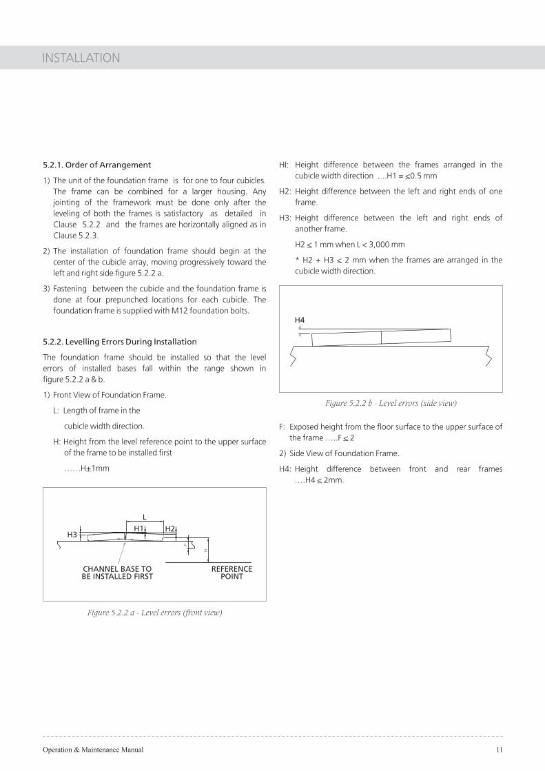
5.2.1. Order of Arrangement
1) The unit of the foundation frame is for one to four cubicles. The frame can be combined for a larger housing. Any jointing of the framework must be done only after the leveling of both the frames is satisfactory as detailed in Clause 5.2.2 and the frames are horizontally aligned as in Clause 5.2.3.
2) The installation of foundation frame should begin at the center of the cubicle array, moving progressively toward the left and right side �gure 5.2.2 a.
3) Fastening between the cubicle and the foundation frame is done at four prepunched locations for each cubicle. The foundation frame is supplied with M12 foundation bolts.
5.2.2. Levelling Errors During Installation
The foundation frame should be installed so that the levelerrors of installed bases fall within the range shown in�gure 5.2.2 a & b.
1) Front View of Foundation Frame.
L: Length of frame in the
cubicle width direction.
H: Height from the level reference point to the upper surface of the frame to be installed �rst
��H+1mm
Figure 5.2.2 a - Level errors (front view)
REFERENCEPOINT
CHANNEL BASE TOBE INSTALLED FIRST
H3H1 H2
L
HI: Height difference between the frames arranged in the cubicle width direction ....H1 = <0.5 mm
H2: Height difference between the left and right ends of one frame.
H3: Height difference between the left and right ends of another frame.
H2 < 1 mm when L < 3,000 mm
* H2 + H3 < 2 mm when the frames are arranged in the cubicle width direction.
F: Exposed height from the �oor surface to the upper surface of the frame �..F < 2
2) Side View of Foundation Frame.
H4: Height difference between front and rear frames �.H4 < 2mm.
Figure 5.2.2 b - Level errors (side view)
H4

Operation & Maintenance Manual 12
INSTALLATION
5.2.3. Horizontal Deviations
Horizontal deviations of frames in the lateral and longitudinal directions should be within the range shown in �gure 5.2.3.
A: Distance from the reference point to the cubicle installation start point
......................A < 1 mm
B: Distance from the reference point to the front side of the frame
......................B < 1 mm
C: Longitudinal deviation (in the front and back direction) between the frames arranged in the cubicle lateral direction
......................C < 1 mm
D: Gap between the laterally arranged, adjacent frames
......................D < 1 mm
Figure 5.2.3 - Longitudinal deviations (top view)
5.2.4. Foundation Frame
After the foundation frame installation is completed, �ll the hollowed �oor around the perimeter of the frame with cement as in Figure 16.
5.3. Cubicle Installation
5.3.1. Location of Fastenings
GIS is divided into unit cubicles. Parts (bolts, nuts, etc) used for installation are packed in a vinyl bag with a tag and attached to the cubicle body.
5.3.2. Order of Installation
1) Draw cubicle reference line on the foundation frame. These reference lines will serve a guide for more accurate alignment of the cubicle.
2) Remove the transportation bolt on the top of the cubicle.
3) Locate the �rst panel onto the center position with the aid of a hydraulic jack, making sure that its front base channel is aligned to the reference line. If the alignment is good, the four foundation bolts can be quite easily inserted into the framework holes.
4) When panel coupling is done at site check before mounting that the O-ring surface is neither scoured nor is any foreign matter adhering to it. Any trapped foreign substance may result in the leakage of SF6 gas. Apply a thin �lm of gel onto the groove of the Aluminium plate and then insert the O-ring into this groove making sure that no sand or dirt is deposited onto the plate. Af�x this plate onto the side opening of the busbar compartment and then proceed in the same manner for the side opening in the adjacent cubicle. Fasten the cubicle together using M12 bolts (with a fastening torque of
Figure 5.2.4 - Cement Filling
FOUNDATIONFRAME
CEMENT MUST BE SAMELEVEL WITH THE FRAME
TRENCH
BASE TO BEINSTALLED FIRST
REFERENCEPOINT
A
B D
INSTALLATIONSTART POINT
C
FRONT SIDEOF CUBICLE

Operation & Maintenance Manual 13
INSTALLATION
Figure 5.3.2 - Connecting the Adjacent Panel
75 NM) making sure that there is a maximum gap of 1mm in between plate and cubicle. Refer to �gure 5.3.2. Repeat the same procedure as in item 5 & 6 for the main bus.
5) Next, using the interpanel coupling bolts, fasten the lowermost jointing portions. After arranging all cubicles in
this way, fasten the remaining coupling bolts (with a fastening torque of 75 NM). Fasten the cubicle body to the bases.
6) Tighten the M12 foundation bolts to the appropriate torque or tag welding should be done to base frame.
5.3.3. Connecting Buses
When panel coupling is done at site buses are provided at the back of each cubicle. After the cubicle coupling is complete, connect the buses as below.
1) Ensure that the connecting surfaces of the buses are cleaned with a dry & clean lint free cloth. Cleanliness of the internal parts is essential to problem-free operation in service condition.
2) Connect the jointing portions with bolts and nuts with a fastening torque. For bolt size of M12 / M10 torque shall be 75 NM / 47NM respectively.
3) Before closing the covers, conduct a further check on tightness of joints with contact resistance measurement of the complete bus.
4) Attach the 0-ring to the seal cover for the rear bus compartment in the same manner as described in 5.3.2 items 6, and mount the cover to the bus compartment opening by fastening M12 nuts on the studs with a fastening torque of 75 NM.
5) After completely sealing the bus compartment, connect a vacuum pump to the gas pipe at the front of the cubicle. Evacuate the cubicle and then supply the speci�ed amount of SF6 gas into the cubicle (1.35kg/cm2).
6) After SF6 gas is sealed, check that there is no gas leakage from the sealed portion by using a leakage detector.

Operation & Maintenance Manual 14
INSTALLATION
Figure 5.3.5 - Assembly of The Earthing Bus
Earth Bar
Connection of Earth BarBetween 2 Panels
The procedure for �xing the gland plate is as below:
a) The gland plate can be cut into two for easy installation.
b) Measure the diameter of the cable.
c) Cut a semicircle on each half of the gland plates to match the cable diameter.
d) Adjust the position of the power cable and mount the cable gland plates onto the welded studs at the cubicle base plate. Tighten the nuts securely.
e) If there is any gap between the power cables to �ll the gap with sealing compound.
f) The Cable screen should be properly connected to the panel earthing.
Note: Connect only one end of the cable earth and not both. For single core cables, there should be a gap between the split plates and the same to be sealed with compound. This is to prevent eddy current circulation.
5.6. Inspection after Installation
5.6.1. General Inspection
1) Check that the door can be smoothly opened and closed.
2) Make sure that the bolts and nuts that were tightened during installation are not loose.
3) Factory-tightened bolts and nuts are torque-marked with a red paint. Check that the marks on these fastenings are not shifted.
4) Check that the earthing bars are correctly connected and that the earth is connected at one point to the substation earthing.
5) Inspect all protection relays and meters. Remove shipping stops, if any.
6) Check the connection for control wiring.
7) Clean complete panel from inside and outside.
5.3.5. Connecting the Earthing Bus
The earthing bus is provided at the lower back of each cubicle. After the cubicle and busbar coupling is completed, connect the earthing buses. The GIS is divided into unit cubicles as shown in �gure 5.3.5 and the earthing bus is likewise divided at the same positions.
1) The earth terminal is provided at the left-end unit of the cubicle array. Draw out the earthing wire from here.
2) Determine the earthing wire drawout position according to the separate GIS �oor plan.
3) The earthing wire should have a minimum of 180mm² stranded bare hard copper wire.
4) Cable earthing shall be done on holes provided on earth bar.
5.4. Connecting Control Wiring
The multicore cable termination for the control cable is provided at the front on the right side. Connection should be made according to the connection diagram given.
Precautions:
The terminals must be tightly, fastened.
Check the tightness of all terminals before energizing.
5.5. Connecting Power Cable
Termination and connection of the power cable should follow the instructions of cable termination manufacturer.
Terminate power cable into bushing. Ensure correct phase co-ordination. Insert termination cables into sockets located at the rear compartment and secure with screws. Align cable and support cables properly to avoid tension.

Operation & Maintenance Manual 15
COMMISSIONING
This section is a guide to the minimum checks and tests that should be performed on site prior to energising the equipment.
6.1. PRELIMINARY CHECKS
Preliminary inspections should be carried out prior to the connection of the high voltage supply:
1) Check the mechanical and electrical interlocks for correct operation.
2) Check that the switchboard is earthed to the station earthing.
3) Check the gas monitors for correct operating pressure within the green zone.
4) Check that the control power is on.
5) Conduct a primary current injection on the protection relay to ensure functional operation with proper test set.
6) Perform a dielectric test on the power cables to appropriate standards.
7) Conduct an operational test on the panel's control and protection system.
8) Check the general condition of the switchboard for any abnormalities that will affect operations.
9) Check external equipment such as remote controls, auxiliary power source and substation condition.
6.2. TESTING
On site test for the gas-�lled compartments should include the
following:
a) Hipot test of the main circuits. (PT should be isolated from
the main circuit before test)
b) Moisture content of gas one day after gas �lling. (PT shall
be isolated from main circuit before Hipot Test)
c) Contact resistance & Insulation resistance
d) Current Injection on Primary & Secondary Circuit
6.3. START-UP
1) During start-up, safety regulations should be observed.
2) Ensure that all the switch-disconnect ors and circuit breakers are in off position.
3) Remove any connecting or shorting links used during the preliminary tests.
4) Energise the switchboard step-by-step, observing all signals and indicators.
5) Check the phasing of the incomers.
6) Watch for any abnormalities.
6.4 SWITCHING OPERATIONS
6.4.1.3-POSITION ISOLATION
The 3-position disconnecting switch selects one of three positions-ON, OFF and Earth by a pair of blades.
The cable side may be earthed through the circuit breaker. It can be electrically and mechanically interlocked with an associated circuit breaker. For details, refer to the relevant instruction manual.
Manual operation: Please refer to the attached manual (and the caution plate on the operating device). for the operation of the Disconnecting Switch.
Electrical operation: As a precaution for electrical operation, the manual operation handle must be OUT. After the interlock is cancelled, turn the handle of the isolator control switch on the front door panel. Only one disconnecting switch can be operated at any one time.
This section is a guide to the minimum checks and tests that should be performed on site prior to energising the equipment.
6.4.2. Interlocks between VCB and 3-Position
Disconnecting Switch.
The disconnecting switch cannot interrupt load current. Hence, the switch can only be operated when the breaker is OFF.
When the breaker is ON, the mechanical and electrical interlocks prevent the disconnecting switch from being operated.
In addition, closure of breaker is not possible when the disconnecting switch operation is in progress. Operation of the switches or breaker is not possible with the shutter of the switch opened.
PRECAUTION: The interlock system may differ from case to case. Refer to the operating system in the schematic drawings.
6.0 COMMISSIONING

Operation & Maintenance Manual 16
COMMISSIONING
6.4.3. Circuit Breaker Operation
Manual operation: Refer to the Breaker Installation Manual and the caution plate of the operating device for the operation of the breaker.
Electrical operation: Turn the local breaker control switch (TNC) handle on the front door panel to OFF or ON or remotely switch the breaker. The status of the device can be checked with the indicators located at the front door.
6.4.4. Earthing of Bus and Switches
An interlock allows the bus to be earthed when all the feeder switches are disconnected from the bus (Dead Bus Check).
This is to ensure the respective bus is dead before earthing. This applies to both single and double bus design.
Motorised version of the earth switch is provided as standard package.
Unless speci�ed, only a manual earth switch is allocated. Any special interlocks for earthing operations will be shown in the technical project drawings.
6.5. - Safety interlocks in GIS Switchgears
Following Interlocks are provided in GIS switchgear for safety purpose during operation & maintenance :-
1. Mechanical & Electrical interlocks prevent the operation of disconnector switch, when the breaker is ON.
2. Disconnector switch can be operated only when VCB is off.
3. Closure of VCB is not possible when the disconnector switch is in operation.
4. At a time, Disconnector switch can be operated either electrically or mechanically but not simultaneously.
5. Closure of VCB is not possible unless the spring is fully charged.
Padlocking Facility :-
1. Metering & DS mechanism compartment door handle.
2. VCB compartment door handle.
3. Aux./ front cable entry compartment door handle.
4. DS operating hole pad loack.
Visual Indications :-
1. ON & OFF status of VCB.
2. ON , OFF & EARTH status of Disconnector Switch.
3. Operation counter (5digit) on VCB front facia.
4. Spring Charged/Discharged indication �ag on VCB front facia.
5. SF6 Gas pressure monitoring device on VCB compartment door facia for VCB & DS compartment tank.
6. SF6 Gas pressure monitoring device on Metering & DS mechanism compartment door facia for busbar chamber tank. This device is provided in any one panel of the board as bus bar chamber tank is common.
Optional Interlock and Visual Indication :-
Following Optional interlocks can be provided:-
1. M.I.L. solenoid interlock is provided to prevent opening of rear cable cover.
2. VCB is tripped electrically if SF6 Gas pressure falls below the minimum permissible value i.e., 1.2 bars.
3. Semaphore indication is provided.
Operation & Maintenance Manual 17
COMMISSIONING
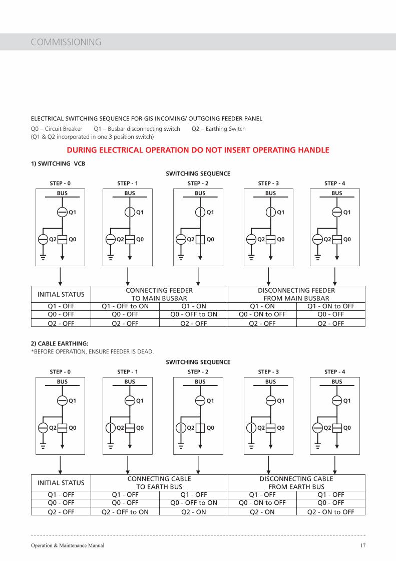
ELECTRICAL SWITCHING SEQUENCE FOR GIS INCOMING/ OUTGOING FEEDER PANEL
Q0 � Circuit Breaker Q1 � Busbar disconnecting switch Q2 � Earthing Switch(Q1 & Q2 incorporated in one 3 position switch)
INITIAL STATUS
Q1 - OFFQ0 - OFFQ2 - OFF
CONNECTING FEEDER TO MAIN BUSBAR
Q1 - OFF to ONQ0 - OFF
Q1 - ONQ0 - OFF to ON
Q2 - OFF Q2 - OFF
DISCONNECTING FEEDER FROM MAIN BUSBAR
Q1 - ON to OFFQ0 - OFF
Q2 - OFF Q2 - OFF
Q1 - ONQ0 - ON to OFF
SWITCHING SEQUENCE
STEP - 0
BUS
Q0
Q1
Q2
STEP - 1
BUS
Q0
Q1
Q2
STEP - 2
BUS
Q0
Q1
Q2
STEP - 3
BUS
Q0
Q1
Q2
STEP - 4
BUS
Q0
Q1
Q2
1) SWITCHING VCB
INITIAL STATUS
Q1 - OFFQ0 - OFFQ2 - OFF
CONNECTING CABLETO EARTH BUS
Q1 - OFFQ0 - OFF
Q1 - OFFQ0 - OFF to ON
Q2 - OFF to ON Q2 - ON
DISCONNECTING CABLEFROM EARTH BUS
Q1 - OFFQ0 - OFF
Q2 - ON Q2 - ON to OFF
Q1 - OFFQ0 - ON to OFF
SWITCHING SEQUENCE
STEP - 0
BUS
Q0
Q1
Q2
STEP - 1
BUS
Q0
Q1
Q2
STEP - 2
BUS
Q0
Q1
Q2
STEP - 3
BUS
Q0
Q1
Q2
STEP - 4
BUS
Q0
Q1
Q2
2) CABLE EARTHING:*BEFORE OPERATION, ENSURE FEEDER IS DEAD.
DURING ELECTRICAL OPERATION DO NOT INSERT OPERATING HANDLE

Operation & Maintenance Manual 18
COMMISSIONING
Table 5: List of Inspection Items
Category Description
Externals
Open - close indication: lamp indication
Abnormal noise and smell
Rust and damage of Cubicle
Tightness of fastenings
Number of operations
Structural
Cracks or breaks of bushing
Broken wire
Tightness of terminalsof low - voltage circuit
wiring
Overheat and discoloration of low voltage circuit wiring terminals
Rust and damage of air- insulated section inside cubicle
Rust and damage of gas piping
Gas pressure
Monitor indication ( if Monitor is provided)
Operating devices
Cleaning oiling and greasing
Facility as a whole
Facility as a whole
Circuit breaker
Tightness of terminalsof low-voltage circuit
wiring
Conduction of auxiliary switches
Tightness of bolts and nuts
Internal check of operation mechanisms
During patrol
During patrol
During patrol
Once every3 years
During patrol
Once every6 years
IsolatorWith earthing switch
Once every3 years
Once every6 years
Once every3 years
Once every6 years
Once every3 years
Once every3 years
Inspection item Routine
patrol inspection
Ordinary inspection
Detailed inspection
Servicing Interval Target equipment

Operation & Maintenance Manual 19
MAINTENANCE AND INSPECTION
GIS is designed to be maintenance-free, requiring only very simple maintenance and inspection, lowering the running cost.
To keep the desired level of performance of the installed devices, enable early detection of faulty parts and thereby forestall possible troubles, it is recommended that the following check is performed according to IEC 1208:
Inspection ~ to predict actual condition
Servicing ~ to preserve speci�ed conditions
Repairs ~ to reestablish speci�ed conditions
Maintenance servicing may only be performed by trained specialists familiar with the peculiar characteristics of the switchboard. It is recommended that L&T engineers be called in to carry out some critical maintenance or repair works.
7.1. Fundamental Philosophy of Maintenance and Inspection
- The gas-sealed sections are continually monitored by the gas monitoring device so it does not require a periodical overhaul and inspection.
- It is recommended that an ordinary inspection centering on operations. Check be performed one year after installation and there after once every 2-4 years depending on operating and local conditions.
- It is recommended that operation mechanisms for circuits breakers and other devices be subjected to a detailed inspection once every 6 years.
- When any abnormal conditions is detected or when a speci�ed number of operations is reached, an inspection should be performed.
7.2. Classi�cation of Maintenance and Inspection
1) Routine Patrol Inspection
This inspection is performed externally while the panel is in operation such as voltage and current readings and any deviation from normal conditions. This inspection is part of the routine patrol on the facility as a whole.
2) Periodically Inspection (Ordinary and Detailed)
This inspection is performed periodically at speci�ed intervals to keep the GIS and installed devices in good condition and at the required level of performance.
- Ordinary inspection:
GIS operation is not interrupted and check is made mainly external such as the effects of pollution or any other environmental in�uences.
- Detailed inspection:
GIS operation is interrupted and checked for protection and control functions and operations of signaling devices and interlock Mechanisms. Parts replacement is done according to criteria.
3) Servicing.
Servicing is performed in the following cases:
- when an abnormal condition is found as a result of inspection and
- when a speci�ed number of operation is reached. Refer to breaker and switch manuals for further detailed instructions.
Basic work on the panels should include but not limited to the following:
- general cleaning of the panels. Clean off all contamination and condensation when panels are installed in the tropics. Remove any dust or dirt deposits, which can be lightly swept off with a lint free cloth. Remove any sticky and greasy deposits on insulators with a lint-free cloth dipped in an approved cleaning agent.
- Procedure as in detailed inspection.
7.0 MAINTENANCE AND INSPECTION

Operation & Maintenance Manual
OPERATION AND MAINTENANCE MANUALTYPE GIS DISCONNECTING SWITCH
Introduction, Speci�cations, Disconnecting Switch,Operating Mechanism, Interlock FeaturesMaintenance & Inspection Criteria and StandardAccessories
Operation & Maintenance Manual
CONTENTS
SubCl No
DescriptionClNo
PageNo
1.0
2.0
3.0
4.0
5.0
2.12.2
3.13.1.13.1.23.23.2.13.2.23.2.33.33.4
4.14.24.3
5.1
INTRODUCTION
SPECIFICATIONSSTANDARDS & OPERATING CONDITIONSTECHNICAL DATA
DISCONNECTING SWITCHEXTERNAL VIEWFACIA OF DISCONNECTING SWITCHPOSITION OF SWITCH BLADESOPERATING MECHANISMELECTRICAL OPERATIONMANUAL OPERATIONEMERGENCY OPERATIONINTERLOCK FEATURESSTANDARD WIRING DIAGRAM
MAINTENANCE & INSPECTION CRITERIAINSPECTION & SERVICING CRITERIACONTENTS OF INSPECTIONCHECK POINTS FOR MAINTENANCE & INSPECTION
STANDARD ACCESSORIESMANUAL OPERATING HANDLE
01
020202
03030304050506070708
09909010
1111

INTRODUCTION
Operation & Maintenance Manual 01
1.0 INTRODUCTIONThis manual describes the handling and operation methods for the disconnecting switch installed in the gas-insulated switchgear panel.
The disconnecting switch is dedicated for installation in the gas-insulated switchgear type GV3/GV3D and its performance is guaranteed under the condition that a speci�ed pressure of SF6 gas is sealed in the GIS.
The conditions of use shall conform with those stipulated inIEC-62271-102. Other conditions are as speci�ed in this manual.
DS30For safe, long service, this manual should be read for thorough understanding and be kept for quick reference.
DisconnectingSwitches

SPECIFICATIONS
Operation & Maintenance Manual 02
2.1. - Standards and Operating Conditions:
Applicable standard: IEC 129.Operating conditions: Switch is mounted in type GV cubicle with minimum gas pressure of 1.2 bars absolute above atmosphere at 20°C.
2.2. - Technical Data:
Electrical Characteristics
Rated Voltage
2500A
Table 2.2 - Technical Data
2.0 SPECIFICATIONS
2000A1250A630A
kV
Rated Current
Rated Frequency
Rated Short Time Current
Rated short circuitMaking Current
Rated short circuit symmetricbreaking Current
Rated Lighting ImpulseVoltage (1.2/50 Micro Sec.)
Rated a.c. 1 min pf voltage
A
Hz
kA/3sec
kAp
kA
kVp
kV rms
36
50
630 1250 2000 2500
25/31.5
63/80
25/31.5
170
70
SF6 Gas Sealing Pressure kg/cm²0abS@20 C
1.35
Operating method Motor-spring/ Manual-spring operation
Operation Voltage 110 / 220 V DC
Operation Current 1-3.5A at 110 / 220 VDC
Mechanical operation life 1000 operations
DISCONNECTING SWITCH
Operation & Maintenance Manual 03
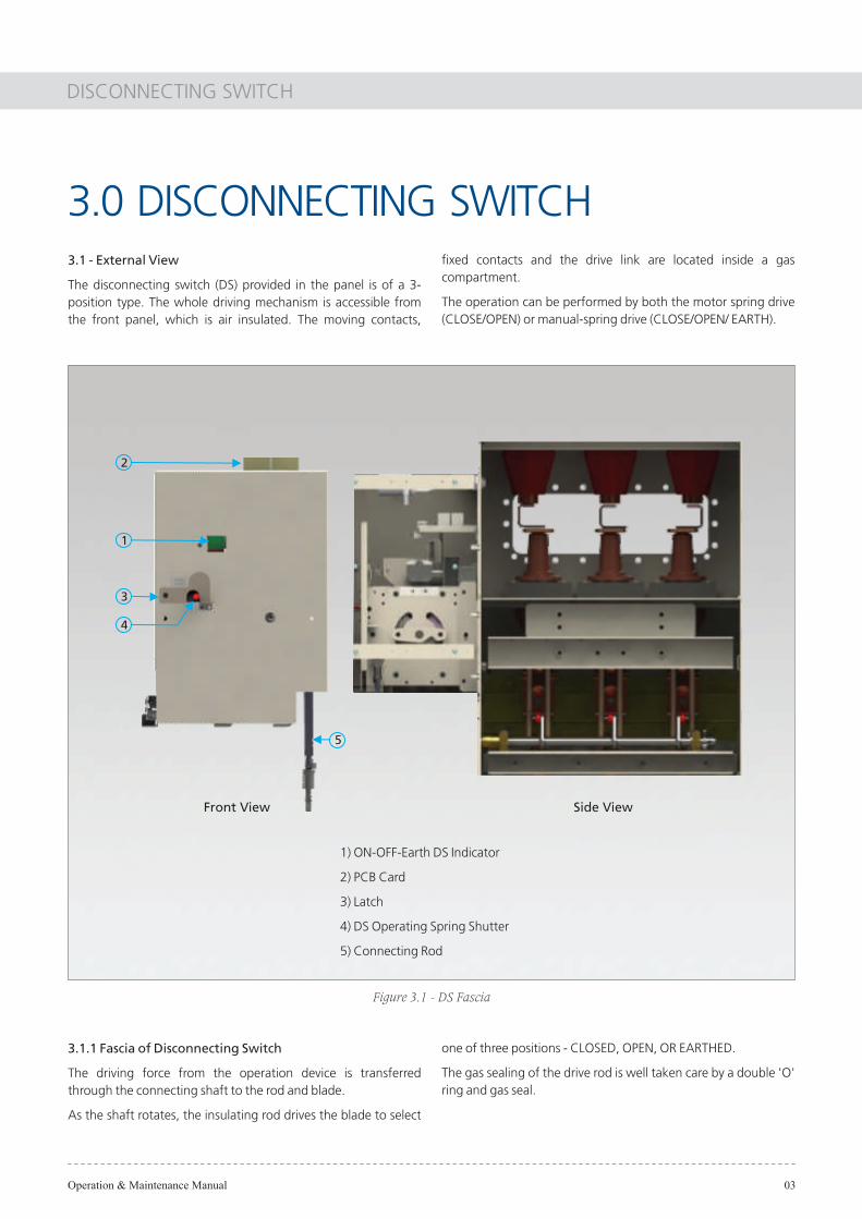
3.1 - External View
The disconnecting switch (DS) provided in the panel is of a 3-position type. The whole driving mechanism is accessible from the front panel, which is air insulated. The moving contacts,
3.0 DISCONNECTING SWITCH
Figure 3.1 - DS Fascia
3.1.1 Fascia of Disconnecting Switch
The driving force from the operation device is transferred through the connecting shaft to the rod and blade.
As the shaft rotates, the insulating rod drives the blade to select
�xed contacts and the drive link are located inside a gas compartment.
The operation can be performed by both the motor spring drive (CLOSE/OPEN) or manual-spring drive (CLOSE/OPEN/ EARTH).
one of three positions - CLOSED, OPEN, OR EARTHED.
The gas sealing of the drive rod is well taken care by a double 'O' ring and gas seal.
1) ON-OFF-Earth DS Indicator
2) PCB Card
3) Latch
4) DS Operating Spring Shutter
5) Connecting Rod
1
Front View Side View
2
3
5
4

DISCONNECTING SWITCH
Operation & Maintenance Manual 04
3.1.2 - Position of the Switch Blades
The moving contact consists of two coupled blades which can swing over to either sides to mate with the LOSE/EARTH contacts. The CLOSE contacts are mounted on independent resin cast insulators. The contacts are made of drawn copper conductors. Earth contacts are connected to the cubicle framework.
In the CLOSE operation, the blades connect the breaker to the busbar.
Whilst in OPEN operation, the blades are isolated from the breaker and earth.
For EARTH operation, the moving contacts connect breaker to the earth contacts mounted on the disconnect switch frame.
Figure 3.1.2 b - DS in CLOSE Position
Figure 3.1.2 c - DS in EARTH PositionFigure 3.1.2 a - DS Assembly in OPEN Position

DISCONNECTING SWITCH
Operation & Maintenance Manual 05
3.2. - Operating Mechanism
The opening and closing of the disconnecting switch can be electrically or manually operated.
However, the earthing operation is manual with an option for motorised operation.
3.2.1. - Electrical Operation
The driving force of the motor is conveyed to a set of gears and �nally to worm wheel Worm wheel rotates the mechanism main
Figure 3.2.1 - Structure Of Operating Mechanism
shaft, charging the closing spring. Towards the end of the operation, the closing spring will be released and this released energy drives the mechanism to rotate at high speed. This mechanism is connected to DS main shaft through a gas tight coupling. The driving force from the mechanism rotates the main DS shaft which in turn moves the contact blades. At the end of the operation, the mechanism switching is completed with an operation sound. The switch positions (open/ close / earth) are displayed by a mechanical �ag at the front of mechanism housing and indicating lamps are mounted on the front door.
Motor
Main Shaft
Worm Wheel
Closing Spring

DISCONNECTING SWITCH
Operation & Maintenance Manual 06
3.2.2. - Manual Operation
A caution plate, as detailed below, is attached to the cover. Check the interlock before proceeding to operate. The number of rotation for the manual handle is about 17.
To Operate Disconnecting switch manually
1. Remove the Padlock of Latch and rotate the latch � Refer �gure 3.2.2 a
2. Open the shutter in the direction of the arrow - Refer �gure 3.2.2. b
3. Insert the manual handle so that it engages with the pin of the shaft. Refer �gure 3.2.2. c
1) OPEN to CLOSE or EARTH to OPEN positions. Rotating the manual charging handle clockwise will cause the disconnecting switch to be operated.
2) CLOSED to OPEN or OPEN to EARTHED positions.
- Turn the manual handle counter-clockwise in the same manner asabove.
- After completion of the operation, rotate the shutter anticlockwise to release the lock. Then, remove the charging handle. The shutter will return automatically to its original position.
- The manual handle has a torque limiting feature which will cause the handle to slip when a torque in excess of the speci�ed value is applied.
- When the handle slips, do not rotate the handle forcibly.
- Check for the correct direction of rotation. After completion of manual operation i.e. when the switching sound is heard, continue to rotate the operating handle for approx. one and a half turns in the same direction of rotation.
Caution Before Manual Operation
Do not attempt to operate the Disconnecting switch if the circuit breaker is in closed position.
When the circuit breaker is in CLOSED position, interlocks prevents the shutter from being opened.
Figure 3.2.2 a - DS Front with cover
This is to enable the electrical interlocks to reset for the next motor operation.
Rotate the shutter knob anticlockwise to remove the operating handle. The shutter is spring loaded and will automatically close.
The interlock plunger resets as soon as the handle is removed.
SHUTTEROPEN

DISCONNECTING SWITCH
Operation & Maintenance Manual 07
3.2.3. - Emergency Operation
In case of emergency situations such as secondary power failure the following procedure applies.
In the event of secondary power failure, the interlocks will prevent the disconnecting switch from being operated manually. To disable the interlocks of the disconnecting switch for manualoperation of open/close/earth, remove the cover by �rst loosening those screws marked. The shutter interlock cam &plunger which prevents cam rotation are accessible once the cover is removed. Lift the plunger upwards with a screwdriver to free the cam and shutter. The shutter can then be opened and it is possible to insert the manual-charging handle for the required operation.
3.3. - Interlock Features
The basic electrical and mechanical interlocks are provided between the disconnecting switch (DS) and the circuit breaker are as follows:
1) DS can be operated only when the circuit breaker is in open condition.
2) While the DS is in operation, the circuit breaker cannot be closed.
3) On line transfer can be achieved by electrical operation.
Figure 3.2.2 b - DS Front cover without latch Figure 3.2.2 c - DS with handle
SHUTTEROPEN
SHUTTEROPEN

DISCONNECTING SWITCH
Operation & Maintenance Manual 08
3.4. - Standard Wiring Diagram
Figu
re 3
.4 -
Stan
dard
Wir
ing
Dia
gram
MO
TOR
SU
PPLY
:110
VD
C, B
LOC
KIN
G M
AG
NET
IC :1
10V
DC
OPE
NIN
G &
CLO
SIN
G C
IRC
UIT
:110
VD
C
NO
TE :
#1)
L4
& L
5 C
ON
TAC
T C
LOSE
D W
HEN
HA
ND
LE IS
INSE
RTED
.H
AN
DLE
IS IN
SERT
ED.
2) L
7 C
ON
TAC
T C
LOSE
D W
HEN
USE
(1) F
OR
ALL
FEE
DER
& B
US
SEC
TIO
N &
(2) F
OR
TRA
NSI
TIO
N P
AN
EL
LEG
END
DES
CR
IPTI
ON
INTE
RLO
CK
SW
ITC
HC
ON
TAC
T O
PERA
TES
WH
EN D
S SH
UTT
ER IS
MA
NU
ALL
Y O
PERA
TED
(IN
SERT
HA
ND
LE)
- C
ON
TRO
L C
ARD
L4-L
8
a1-a
8
b1-b
8
c1-c
2, c
4, c
6
ILM
XH
1, X
K1
D F R C M
XH
2, X
K2
DS
AU
X. C
ON
TAC
T -O
N
DS
AU
X. C
ON
TAC
T -O
FF
DS
AU
X. C
ON
TAC
T -E
ART
H
INTE
RLO
CK
MA
GN
ET
AuX
. REL
AY
CO
NTR
OL
RELA
Y
DIO
DES
FUSE
RESI
STO
RS
CA
PAC
ITO
R
MO
TOR
*K8
XK
1
*L4
*L4A
XH
1
INTE
RLO
CKSH
UTT
ER
*K9
DS
(WIT
HE.
SW.)
ILM*L
4
9
PRO
GRE
SS
XH
2
XQ
*-10
DS
IN*K10
5
8 12
XK
2
136
10 R2
CIR
CUIT
CLO
SIN
G
D1
R1
D2
1 *K1
7
R2
XH
1
R1
XH
1
D5
14 *K5
5
OPE
NIN
GC
IRCU
IT
*K4
15 XK
1
XK
2
*K3
XH
1
XH
23
R4
R4
D4
XK
1
42 3
XK
1
R3
R3
XK
1D
3
XH
1
*K2
D6
*K7
9F 7
XH
2
XK
2
XK
2
*K6
6 17 XH
2
R6
R7
XK
2
XH
2
R5
M3
*L7A *L
7
M4*L7
R5 1
24
11
MO
TOR
CIR
CUIT
13*L5A
BLU
E
RED
C1 C2
816 M
1
M1
M2
M2
M
12 *L5 *L5O
N
EART
H
OFF
2826
2430
38
2927
2537
39
4442
4056
54
5143
4155
52
53
16 15*L4A
*L4
19
18
21 22
C
NO
NC
#
C
NO
NC
C
NO
NC
#
#
17
*L5B
14
*L4B
*L4B
20 *L7B
*L7B
23
3231
3433
3635
4847
504957 58
*c01
*c02
*c1
*c2
511
*c1
6*c2
12
*c6
33 34
*c6
*c04
*c4
25 26
*c4
*c06
*b01
*b1
3 *b1
4
*b04
*b03
*b02
*b4
*b4
23
*b3
*b2
159
*b3
*b2
1610
24
*b05
*b5
*b5
29 30
*b06
*b6
*b6
35 36
*b07
*b7
*b7
39 40
*a03
*a02
*a01
*a04
*a3
*a3
*a2
*a1
7 *a2
1 *a1
82
13 14
*a4
21 *a4
22
*a05
*a5
27 *a5
28
*a06
*a6
31 *a6
32
*a07
*a7
37 *a7
38
17 *a8
18
*b8
59 *ab
8
60*ab
08
45 46X
Q*-
11*K
11

MAINTENANCE & INSPECTION CRITERIA
Operation & Maintenance Manual 09
The Disconnecting Switches require little maintenance during their normal working life. The criteria shown below shouldbe observed to keep the disconnecting switch serviceable for a long period of time.
4.1. - Inspection and Servicing Criteria
The inspection intervals should be shortened for equipment used in adverse conditions.
4.0 MAINTENANCE &INSPECTION CRITERIA
4.2. - Contents of Inspection
Check points in visual, ordinary and detailed inspection are listed in table 4.1.
Table 4.1 - Inspection Intervals
1) Visual inspection
2) Ordinary inspection
3) Detailed inspection and major service
: Arbitrary time
: Performed every 3 years
: Performed every 6 years or 2000 operations or whenever abnormal condition is found

DISCONNECTING SWITCH
Operation & Maintenance Manual 10
4.3. - Check Points for Maintenance & Inspection
Table 4.3 - Check Points
Externals
OperatingMechanism
Appearance (rust, dewpoint)
ControlCircuit
InspectionVisual Ordinary Detailed
Gas pressure
Open - close indicator
Abnormal noise and smell
Filings and chips, dislocatedparts, foreign matters
Deformation, damage, wear
Loose bolts and nuts
Visual check
Movement of operating spring
Movement of link
Greasing state in sliding androtating parts
Warping or galling of parts
Oiling (machine oil) state insliding and rotating parts
Remove old grease and applynew grease
Lubricationandoperation
Oiling andgreasing
Check for dislocatedconnectors and pins and fordeformation and breaks
Check for loose fastenings ofthe switch terminals and for rust
Contact state of auxiliary switches
Visual check
Check onMechanicalparts
Contact state of limit switches
Device operation test(measurement taken duringmotor operation)
Sequence test (interlockoperation)
Test
Category Check point
STANDARD ACCESSORIES
Operation & Maintenance Manual 11
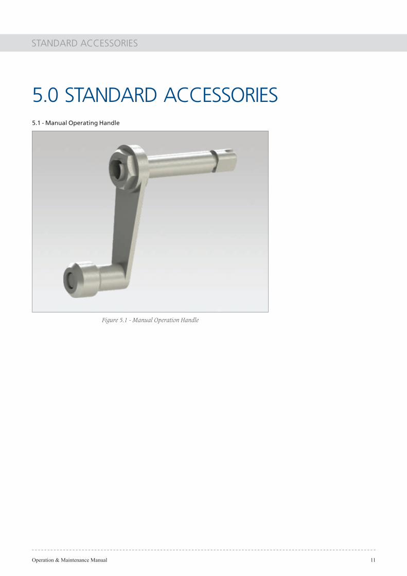
5.1 - Manual Operating Handle
5.0 STANDARD ACCESSORIES
Figure 5.1 - Manual Operation Handle
Operation & Maintenance Manual
OPERATION AND MAINTENANCE MANUALTYPE GIS BREAKER GV3
Introduction, Speci�cations, VCB, Maintenanceand Standard Accessories

1.0
2.0
3.0
4.0
5.0
6.0
2.12.2
3.13.1.13.1.23.23.2.13.2.23.2.33.2.43.33.3.13.3.23.43.5
4.14.2
5.1
INTRODUCTION
SPECIFICATIONSSTANDARDS & OPERATING CONDITIONSTECHNICAL DATA
VACUUM CIRCUIT BREAKERPOLE ASSEMBLYCLOSING OF INTERRUPTER CONTACTSOPENING OF INTERRUPTER CONTACTSVACUUM CIRCUIT BREAKER OPERATING MECHANISMMOTOR CHARGING MECHANISMMANUAL (EMERGENCY) CHARGINGCLOSINGOPENINGOPERATION OF CONTROL CIRCUITCLOSING SPRING CHARGING OPERATIONOPENING OPERATIONFIGURESSTANDARD WIRING DIAGRAM
MAINTENANCEINSPECTION & SERVICING CRITERIACONTENTS OF INSPECTION
STANDARD ACCESSORIESMANUAL CHARGING HANDLE
MANDATORY SPARES
NOTE
01
020202
0303030303030303040404040406
070707
0808
09
10
Operation & Maintenance Manual
CONTENTS
SubCl No
DescriptionClNo
PageNo

INTRODUCTION
Operation & Maintenance Manual 01
1.0 INTRODUCTIONThis manual describes the handling and operation methods for the vacuum circuit breaker types: GV30M25, GV30J25.
The vacuum circuit breaker is dedicated for installation in the GV3 cubicle type Gas insulated switchgear and its performance is guaranteed under the condition that a speci�ed pressure of SF6 gas is maintained in the GIS. The circuit breakers conform to IEC 62271-100 within the parameters of their technical data.
CircuitBreaker
GV3The type GV circuit breakers are not only suitable for frequent switching under normal load conditions but are also capable of a large number of short circuit breaking operations within the restrictions of the technical data. They are also suitable for auto-reclosing.
SPECIFICATIONS
Operation & Maintenance Manual 02
2.1. - Standards and Operating Conditions:
Applicable standard: IEC 62271-200, IEC 62271-100, IEC 62271-102, IEC 60376 & IEC 60480.Mounted in type GV cubicles with a rated gas pressure of 1.35 bars absolute above atmospheric at 20 °C.
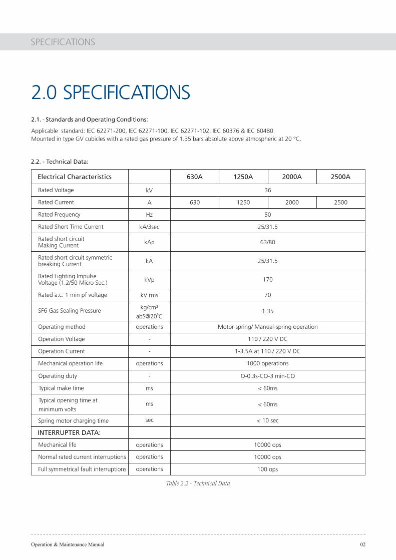
2.2. - Technical Data:
Table 2.2 - Technical Data
2.0 SPECIFICATIONS
O-0.3s-CO-3 min-COOperating duty
< 60ms
< 60ms
< 10 sec
INTERRUPTER DATA:
Mechanical life
Normal rated current interruptions
Full symmetrical fault interruptions
10000 ops
10000 ops
100 ops
Typical make time
Typical opening time at
minimum volts
Spring motor charging time
Electrical Characteristics
Rated Voltage
2500A2000A1250A630A
kV
Rated Current
Rated Frequency
Rated Short Time Current
Rated short circuitMaking Current
Rated short circuit symmetricbreaking Current
Rated Lighting ImpulseVoltage (1.2/50 Micro Sec.)
Rated a.c. 1 min pf voltage
A
Hz
kA/3sec
kAp
kA
kVp
kV rms
36
50
630 1250 2000 2500
25/31.5
63/80
25/31.5
170
70
SF6 Gas Sealing Pressure kg/cm²0abS@20 C
1.35
Operating method Motor-spring/ Manual-spring operation
Operation Voltage 110 / 220 V DC
Operation Current 1-3.5A at 110 / 220 V DC
Mechanical operation life 1000 operations
operations
operations
operations
ms
ms
sec
operations
-
-
-
operations
VACUUM CIRCUIT BREAKER
Operation & Maintenance Manual 03
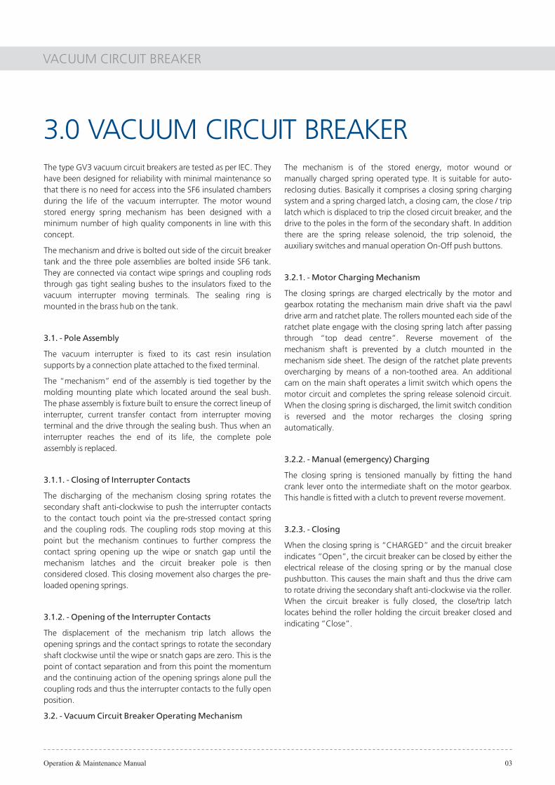
The type GV3 vacuum circuit breakers are tested as per IEC. They have been designed for reliability with minimal maintenance so that there is no need for access into the SF6 insulated chambers during the life of the vacuum interrupter. The motor wound stored energy spring mechanism has been designed with a minimum number of high quality components in line with this concept.
The mechanism and drive is bolted out side of the circuit breaker tank and the three pole assemblies are bolted inside SF6 tank. They are connected via contact wipe springs and coupling rods through gas tight sealing bushes to the insulators �xed to the vacuum interrupter moving terminals. The sealing ring is mounted in the brass hub on the tank.
3.1. - Pole Assembly
The vacuum interrupter is �xed to its cast resin insulation supports by a connection plate attached to the �xed terminal.
The �mechanism� end of the assembly is tied together by the molding mounting plate which located around the seal bush. The phase assembly is �xture built to ensure the correct lineup of interrupter, current transfer contact from interrupter moving terminal and the drive through the sealing bush. Thus when an interrupter reaches the end of its life, the complete pole assembly is replaced.
3.1.1. - Closing of Interrupter Contacts
The discharging of the mechanism closing spring rotates the secondary shaft anti-clockwise to push the interrupter contacts to the contact touch point via the pre-stressed contact spring and the coupling rods. The coupling rods stop moving at this point but the mechanism continues to further compress the contact spring opening up the wipe or snatch gap until the mechanism latches and the circuit breaker pole is then considered closed. This closing movement also charges the pre-loaded opening springs.
3.1.2. - Opening of the Interrupter Contacts
The displacement of the mechanism trip latch allows the opening springs and the contact springs to rotate the secondary shaft clockwise until the wipe or snatch gaps are zero. This is the point of contact separation and from this point the momentum and the continuing action of the opening springs alone pull the coupling rods and thus the interrupter contacts to the fully open position.
3.2. - Vacuum Circuit Breaker Operating Mechanism
3.0 VACUUM CIRCUIT BREAKERThe mechanism is of the stored energy, motor wound or manually charged spring operated type. It is suitable for auto-reclosing duties. Basically it comprises a closing spring charging system and a spring charged latch, a closing cam, the close / trip latch which is displaced to trip the closed circuit breaker, and the drive to the poles in the form of the secondary shaft. In addition there are the spring release solenoid, the trip solenoid, the auxiliary switches and manual operation On-Off push buttons.
3.2.1. - Motor Charging Mechanism
The closing springs are charged electrically by the motor and gearbox rotating the mechanism main drive shaft via the pawl drive arm and ratchet plate. The rollers mounted each side of the ratchet plate engage with the closing spring latch after passing through �top dead centre�. Reverse movement of the mechanism shaft is prevented by a clutch mounted in the mechanism side sheet. The design of the ratchet plate prevents overcharging by means of a non-toothed area. An additional cam on the main shaft operates a limit switch which opens the motor circuit and completes the spring release solenoid circuit. When the closing spring is discharged, the limit switch condition is reversed and the motor recharges the closing spring automatically.
3.2.2. - Manual (emergency) Charging
The closing spring is tensioned manually by �tting the hand crank lever onto the intermediate shaft on the motor gearbox. This handle is �tted with a clutch to prevent reverse movement.
3.2.3. - Closing
When the closing spring is �CHARGED� and the circuit breaker indicates �Open�, the circuit breaker can be closed by either the electrical release of the closing spring or by the manual close pushbutton. This causes the main shaft and thus the drive cam to rotate driving the secondary shaft anti-clockwise via the roller. When the circuit breaker is fully closed, the close/trip latch locates behind the roller holding the circuit breaker closed and indicating �Close�.
VACUUM CIRCUIT BREAKER
Operation & Maintenance Manual 04
3.2.4. - Opening
The circuit breaker can be opened by electrical trip or by the manual open pushbutton. The close / trip latch located behind the roller is displaced and the contact springs and opening springs rotate the secondary shaft clockwise to fully open the circuit breaker and indicating �Open�.
3.3. - Operation of Control Circuit
3.3.1. - Closing Spring Charging Operation
Figure 3.4a shows the control circuit of the circuit breaker when the closing spring is in the charged state and the circuit breaker is open. When the closing spring is discharged it rotates the mechanism main shaft with its switch operating cam and LS is switched on. In this state when M1 & M2 is connected to an auxiliary supply the motor automatically recharges the closing spring and LS is switched off (spring charging time <10secs). During this closing operation, the b contact of the auxiliary switch is turned off, and also the energised relay Y opens it contact Yb to complete the pumping prevention circuit. Thus, if the same close signal stays on, Yb remains open and prevents reclosing of the circuit breaker. The closing circuit is also provided with contact Xb from the control relay which prevents the spring release coil CC being energised while the closing spring is being charged.
3.3.2. - Opening Operation
The tripping circuit is formed by a1-TC. When the circuit breaker is closed and the external operating switch is turned to TRIP the trip coil TC is energised and the circuit breaker opens in<60ms. During the open operation the contact of the auxiliary switch is turned off de-energising the trip coil TC.
Note: the TC terminals are used to monitor the trip circuit.
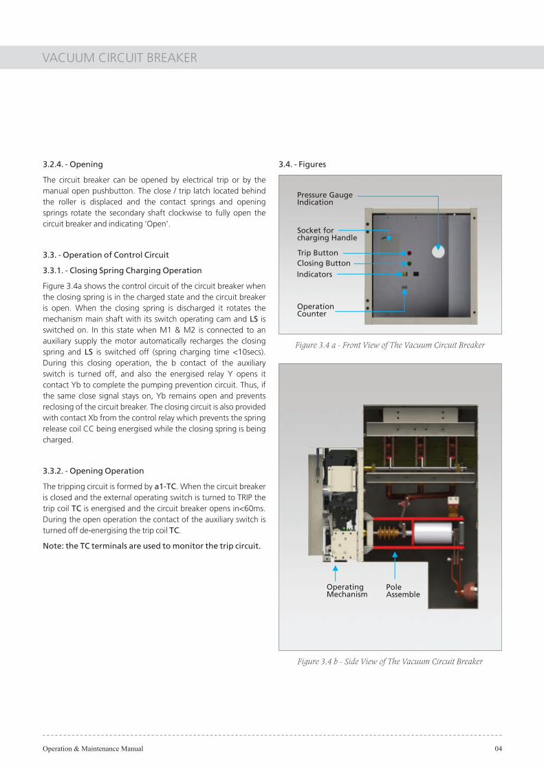
3.4. - Figures
Figure 3.4 a - Front View of The Vacuum Circuit Breaker
Figure 3.4 b - Side View of The Vacuum Circuit Breaker
Pressure GaugeIndication
Trip ButtonClosing Button
Socket forcharging Handle
Indicators
OperationCounter
PoleAssemble
OperatingMechanism

VACUUM CIRCUIT BREAKER
Operation & Maintenance Manual 05
Figure 3.3.4 shows the front view of the operation mechanism with the front panel of the circuit breakers removed.
Figure 3.3.4 b - General Structure of Operation Mechanism Figure 3.3.4 c - Side View of Operation Mechanism
Figure 3.3.4 a - Front View of The Operation Mechanism
Chargingspring
ChargingSpringSocket
VCBMechanism
Motor

VACUUM CIRCUIT BREAKER
Operation & Maintenance Manual 06
3.5. - Standard Wiring Diagram
Figure 3.5 - Motor Stored Energy
31 11 34 3516151413 3321 4117 22
N1
- CONTROL CARD
5
32
7
4
12
1
12
211 8
B03B02A04A03A02 A05 B04N2M2
7
27
LS
M
LS
2542 2423 26 43 44 45
a4a2
TC
a1 a3 a5 b2 b3 b4
H HT
240 Vac L
M1 LS A4A2K A3 A5 B2 B3 B436
B05
46
b5
B5
+ VE
- VE
OFF P/B
b1
CC
X-bX-bC
D5D6
D4 F
R3
D3 X-a
C
R2 R2
Y-b Y-b R4 R4
YX-a
D1
R1R1
X D2
LS
- VE ; 110 V DC
+VE ; 110 V DC
XQ0 4
XQ0 5
6 83 1 9 11 13 15 17 19 21 23
7 210 12 14 16 18 20 22 24
XQ0
XQ0
LEGEND DESCRIPTION
Y
Y-b
X
X-a
X-b
TC
M
CC
AUX. RELAY
Y RELAY N/C CONTACT
CONTROL RELAY
X RELAY N/O CONTACT
X RELAY N/C CONTACT
CLOSING COIL
TRIPPING COIL
SPRING CHARGING MOTOR
b
C
a BKR. AUX. CONTACT - N/O
BKR. AUX. CONTACT - N/C
CAPACITOR
DIODES
RESISTORS
FUSE
LEGEND DESCRIPTION
D1 - D6
R1 - R4
F
IL INTERLOCK SWITCH CONTACT CLOSES WHEN BREAKERIS AT CONNECTED OR DISCONNECTED POSITION.
LS LIMIT SWITCH CONTACT CHANGES OVERWHEN SPRING IS FULLY CHARGED.

MAINTENANCE
Operation & Maintenance Manual 07
Type GV vacuum circuit breakers require little maintenance during their normal working life. The pole assembly including the interrupter is considered maintenance free for the working life of the interrupter, the mechanism require regular inspection and little maintenance.
4.0 MAINTENANCE4.1. - Inspection and Servicing Criteria.
The inspection intervals should be reduced for equipment used in an adverse environment.
Arbitrary time
Table 4.1: Inspection Intervals
4.1.1. Visual inspection:
4.1.3. Detailed inspectionand major service:
Performed every 10,000 operations or 100 Operations at rated short circuit breaking Currentand rated voltage or when the wipe / snatch gap has reduced to 1mm.
Performed every 3 years or 2000 operations4.1.2. Ordinary inspection:
OperationMechanism
InspectionVisual Ordinary Detailed
Visual check
Category Check point
Operation
Greasing
Loose bolts and nuts
Dust and foreign matters
Dislocated parts
Filling and chips
Indication of indicator and Counter
Deformation, damage, wear
Resetting operation of trip prop andclosing prop
Movement of rollers and pins
Warping or galling of parts
Check on reset condition
Remove old grease and apply new grease
Check for dislocated connectors and pinsand for deformation and break
Check for loose fastenings of The switchterminals and for rust
Visual check
Operation of auxiliary switches
Contact state of limit switches
Electrical open-close operation
Check onmechanicalparts
ControlCircuit
Check on wipe dimension (Must be larger than 1mm)
Number of open-close operations (Replace the interrupterwhen 10,000 operations are exceeded)
Abnormal noise
Abnormal smell
Whole circuitbreaker
VacuumInterrupter
Others
4.2. - Contents of Inspection
Check points for visual, ordinary and detailed inspections are listed in table 4.2.
Table 4.2: Check points for maintenance and inspection
STANDARD ACCESSORIES
Operation & Maintenance Manual 08
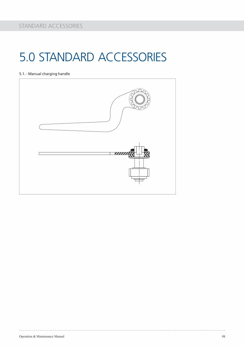
5.1. - Manual charging handle
5.0 STANDARD ACCESSORIES

MANDATORY SPARES
Operation & Maintenance Manual 09
1. Disconnecting Switch Operating Handle
2. VCB Spring Charging Handle
3. VCB Spring Charging Motor
4. Closing Coil
5. Tripping Coil
6. Indications Lamps
7. Electrical Contact grease (Preferred - Mosil EC-111)
8. Mechanical Grease (Preferred - Mosil GM-00)
9. Touchup Paint
Note - While Ordering Spares please mention "Board Drawing Number" as given in Switchboard Name Plate.
6.0 MANDATORY SPARES

Operation & Maintenance Manual 10
NOTES

Operation & Maintenance Manual 11
NOTES
Larsen & Toubro Limited, Electrical Systems & Equipment - Head OfficeGate No. 7, North Wing, Level 1, Saki-Vihar Road, Powai, Mumbai 400 072Tel: +91-22-6705 1748 Fax: +91-22-6705 1556 Email: [email protected]: www.Lntebg.com CIN: L99999MH1946PLC004768
GM
A1
9.0
6.2
014
Sales Offices - InternationalSales Offices - India
India
Gate No.7, Saki-Vihar RoadNorth Wing, Level 1Mumbai 400 072Tel:+91-22-6705 2813Fax:+91-22-6705 1024Email: [email protected]
Saudi Arabia
L&T Electricals Saudi Arabia Company Limited - L. L. CMH-4, Plot: 17+192nd Industrial Area, DammamKingdom of Saudi ArabiaTel: +966-3-8127708Fax: +966-3-8127780Email: [email protected]
UAE
2202, 22nd floorGreen Emirates Tower - AElectra Street, P.O. Box 30803Abu Dhabi, UAETel. : +971-2-676 5988Fax. : +971-2-676 6399Email: [email protected]
Oman
P.O.Box 598, Ruwi, Postal Code-112Sultanate of OmanTel:+968 98034317Mob:+968 98034317EMail: [email protected]
Malaysia
TAMCO SWITCHGEAR (MALAYSIA) SDN BHDSub Lot 24, Lot 16505, Jalan Keluli 1PO Box 2100, Bukit Raja Industrial Area, Section 740802 ShahAlam, Selangor, MalaysiaTel: +603 3361 8200Fax: +603 3341 6200Email: [email protected]
TAMCO Electrical Industries Australia Pty Ltd31 Kitchen Road, Dandenong 3175Melbourne, Victoria, AustraliaTel:+613 9706 7288Fax:+613 9706 9112Email: [email protected]
Australia
1A, 3rd FloorWestlands Business Park04, Chiromo LaneWestlands, PO Box no. 13903 - 00800Nairobi, KenyaTel. : +254-770-412 008Email: [email protected]
Kenya
2 & 3rd Floor, Building No. 209Zone 42, Street 230Najma Intersection, Opp: Doha CinemaC-Ring Road,P.O Box No- 24399Doha, QatarTel: +974-44-239 000Fax: +974-44-551 286Email: [email protected]
Qatar
Indonesia
PT. TAMCO IndonesiaF-36, Jalan Jababeka Raya Jababeka Industrial EstateCikarang Utara, Bekasi, 17530,IndonesiaTel.: +62 21 893 5070 Fax: +62 21 893 5071 Email: [email protected]
Chennai
Hyderabad
Kolkata
Mumbai
New Delhi
L&T Construction CampusTC-1 Building, II FloorMount-Poonamallee Road
Tel:+91-44-2270 6801Fax:+91-44-2270 6930Email: [email protected]
Post Bag 12, Vasantha Chambers2 floor, 5-10-73, Fateh Maidan RoadHyderabad 500 004Tel: +91-40-6672 0210Fax: +91-40-2324 2356Email: [email protected]
Post Bag 6193-B, Shakespeare SaraniKolkata 700 071Tel. : +91-33-4400 2550 / 2558Fax. : +91-33-22827587 / 1025Email: [email protected]
Gate No. 7, North Wing, Level 2Saki-Vihar Road, Powai
Tel:+91-22-6705 3083Fax:+91-22-6705 1556Email: [email protected]
Post Bag 622332, Shivaji MargNew Delhi 110 015Tel: +91-11-4141 9620/9942Fax: +91-11-4141 9625Email: [email protected]
Manapakkam, Chennai 600 089
Mumbai 400 072
Vadodara
Radhadaya Complex, J. P. RoadVadodara 390 015Tel: +91-265-66136 37/38Fax: +91-265-2336 184Email: [email protected]
Bengaluru
Bengaluru 560001Tel: 080-25020319Fax: 080-25596397Email: [email protected]
The information contained herein is correct at time of printing, but as the products and its manufacturing processes are being developed continuously,this information is subject to change without notice and the company cannot be held liable for any alleged misinterpretation howsoever arising.
Registered Office:L&T House, N. M. MargBallard EstateMumbai 400 001, INDIA