operation manual - apc by schneider electric · operation manual network management card 2 for...
TRANSCRIPT

Operation Manual
Network Management Card 2forModular PDU, RPP, and RDP
PDPM138H-5UPDPM138H-RPDPM144FPDPM277HPDPM72F-5U
990-9931-001
Publication Date: June 2016

Schneider Electric Legal DisclaimerThe information presented in this manual is not warranted by Schneider Electric to be authoritative, error free,
or complete. This publication is not meant to be a substitute for a detailed operational and site specific
development plan. Therefore, Schneider Electric assumes no liability for damages, violations of codes,
improper installation, system failures, or any other problems that could arise based on the use of this
Publication.
The information contained in this Publication is provided as is and has been prepared solely for the purpose of
evaluating data center design and construction. This Publication has been compiled in good faith by Schneider
Electric. However, no representation is made or warranty given, either express or implied, as to the
completeness or accuracy of the information this Publication contains.
IN NO EVENT SHALL SCHNEIDER ELECTRIC, OR ANY PARENT, AFFILIATE OR SUBSIDIARY COMPANY
OF SCHNEIDER ELECTRIC OR THEIR RESPECTIVE OFFICERS, DIRECTORS, OR EMPLOYEES BE
LIABLE FOR ANY DIRECT, INDIRECT, CONSEQUENTIAL, PUNITIVE, SPECIAL, OR INCIDENTAL
DAMAGES (INCLUDING, WITHOUT LIMITATION, DAMAGES FOR LOSS OF BUSINESS, CONTRACT,
REVENUE, DATA, INFORMATION, OR BUSINESS INTERRUPTION) RESULTING FROM, ARISING OUT,
OR IN CONNECTION WITH THE USE OF, OR INABILITY TO USE THIS PUBLICATION OR THE CONTENT,
EVEN IF SCHNEIDER ELECTRIC HAS BEEN EXPRESSLY ADVISED OF THE POSSIBILITY OF SUCH
DAMAGES. SCHNEIDER ELECTRIC RESERVES THE RIGHT TO MAKE CHANGES OR UPDATES WITH
RESPECT TO OR IN THE CONTENT OF THE PUBLICATION OR THE FORMAT THEREOF AT ANY TIME
WITHOUT NOTICE.
Copyright, intellectual, and all other proprietary rights in the content (including but not limited to software, audio,
video, text, and photographs) rests with Schneider Electric or its licensors. All rights in the content not expressly
granted herein are reserved. No rights of any kind are licensed or assigned or shall otherwise pass to persons
accessing this information.
This Publication shall not be for resale in whole or in part.

Table of Contents
Overview................................................................................................................1Important Information . . . . . . . . . . . . . . . . . . . . . . . . . . . . . . . . . . . . . . . . . . . . . . .1
About This Manual . . . . . . . . . . . . . . . . . . . . . . . . . . . . . . . . . . . . . . . . . . . . . . . .2Related Documents . . . . . . . . . . . . . . . . . . . . . . . . . . . . . . . . . . . . . . . . . . . . . . .2User Comments . . . . . . . . . . . . . . . . . . . . . . . . . . . . . . . . . . . . . . . . . . . . . . . . . .2
Safety . . . . . . . . . . . . . . . . . . . . . . . . . . . . . . . . . . . . . . . . . . . . . . . . . . . . . . . . . . .3
IMPORTANT SAFETY INSTRUCTIONS . . . . . . . . . . . . . . . . . . . . . . . . . . . . . . .3Regulatory Agency Approval . . . . . . . . . . . . . . . . . . . . . . . . . . . . . . . . . . . . . . . .4Waste Electrical and Electronic Equipment (WEEE) disposal . . . . . . . . . . . . . . .4
Additional Safety Information . . . . . . . . . . . . . . . . . . . . . . . . . . . . . . . . . . . . . . . . .5
Before you begin . . . . . . . . . . . . . . . . . . . . . . . . . . . . . . . . . . . . . . . . . . . . . . . . .5Operation and Adjustments . . . . . . . . . . . . . . . . . . . . . . . . . . . . . . . . . . . . . . . . .5
Commissioning ......................................................................................................6Pre-Start Checklists . . . . . . . . . . . . . . . . . . . . . . . . . . . . . . . . . . . . . . . . . . . . . . . .6
Initial Inspection Checklist . . . . . . . . . . . . . . . . . . . . . . . . . . . . . . . . . . . . . . . . . .6Electrical Inspection Checklist . . . . . . . . . . . . . . . . . . . . . . . . . . . . . . . . . . . . . . .6User Interface Inspection Checklist . . . . . . . . . . . . . . . . . . . . . . . . . . . . . . . . . . .6Final Inspection Checklist . . . . . . . . . . . . . . . . . . . . . . . . . . . . . . . . . . . . . . . . . . .6
Start-up Inspection Checklist . . . . . . . . . . . . . . . . . . . . . . . . . . . . . . . . . . . . . . . . .7
Operation ...............................................................................................................8Display Interface . . . . . . . . . . . . . . . . . . . . . . . . . . . . . . . . . . . . . . . . . . . . . . . . . .8
Navigate the display interface . . . . . . . . . . . . . . . . . . . . . . . . . . . . . . . . . . . . . . .8Top dynamic display . . . . . . . . . . . . . . . . . . . . . . . . . . . . . . . . . . . . . . . . . . . . . . .9Main Menu Screen . . . . . . . . . . . . . . . . . . . . . . . . . . . . . . . . . . . . . . . . . . . . . . . .9Password protection . . . . . . . . . . . . . . . . . . . . . . . . . . . . . . . . . . . . . . . . . . . . . . .9Menu tree . . . . . . . . . . . . . . . . . . . . . . . . . . . . . . . . . . . . . . . . . . . . . . . . . . . . . .10
Modules Submenu . . . . . . . . . . . . . . . . . . . . . . . . . . . . . . . . . . . . . . . . . . . . . . . .11
View Module status . . . . . . . . . . . . . . . . . . . . . . . . . . . . . . . . . . . . . . . . . . . . . .11View Power Distribution Module information . . . . . . . . . . . . . . . . . . . . . . . . . . .12View circuit status information . . . . . . . . . . . . . . . . . . . . . . . . . . . . . . . . . . . . . .13View load status . . . . . . . . . . . . . . . . . . . . . . . . . . . . . . . . . . . . . . . . . . . . . . . . .13View total load by phase . . . . . . . . . . . . . . . . . . . . . . . . . . . . . . . . . . . . . . . . . . .14View output voltages . . . . . . . . . . . . . . . . . . . . . . . . . . . . . . . . . . . . . . . . . . . . .14View the log . . . . . . . . . . . . . . . . . . . . . . . . . . . . . . . . . . . . . . . . . . . . . . . . . . . .15Clear the log . . . . . . . . . . . . . . . . . . . . . . . . . . . . . . . . . . . . . . . . . . . . . . . . . . . .15View the list of active alarms . . . . . . . . . . . . . . . . . . . . . . . . . . . . . . . . . . . . . . .16
NMC2 for Modular PDU, RPP, RDP i

Configuration........................................................................................................17Settings . . . . . . . . . . . . . . . . . . . . . . . . . . . . . . . . . . . . . . . . . . . . . . . . . . . . . . . .17
Set up the network . . . . . . . . . . . . . . . . . . . . . . . . . . . . . . . . . . . . . . . . . . . . . . .17Set the name and location of the circuits . . . . . . . . . . . . . . . . . . . . . . . . . . . . . .17Set individual alarm thresholds . . . . . . . . . . . . . . . . . . . . . . . . . . . . . . . . . . . . . .18Set alarm thresholds for all Modules in the PDU . . . . . . . . . . . . . . . . . . . . . . . .19Set and change the password settings . . . . . . . . . . . . . . . . . . . . . . . . . . . . . . . .19Change the display settings . . . . . . . . . . . . . . . . . . . . . . . . . . . . . . . . . . . . . . . .20Change date and time . . . . . . . . . . . . . . . . . . . . . . . . . . . . . . . . . . . . . . . . . . . .20
Modbus Configuration..........................................................................................21Modbus Serial Configuration . . . . . . . . . . . . . . . . . . . . . . . . . . . . . . . . . . . . . . .21Modbus TCP Configuration . . . . . . . . . . . . . . . . . . . . . . . . . . . . . . . . . . . . . . . .22
Network Management Configuration ...................................................................23Overview . . . . . . . . . . . . . . . . . . . . . . . . . . . . . . . . . . . . . . . . . . . . . . . . . . . . . . .23
Connections . . . . . . . . . . . . . . . . . . . . . . . . . . . . . . . . . . . . . . . . . . . . . . . . . . . .23Initial setup . . . . . . . . . . . . . . . . . . . . . . . . . . . . . . . . . . . . . . . . . . . . . . . . . . . . .23Device IP Configuration Wizard . . . . . . . . . . . . . . . . . . . . . . . . . . . . . . . . . . . . .24Supported Web browsers . . . . . . . . . . . . . . . . . . . . . . . . . . . . . . . . . . . . . . . . . .24Network management features . . . . . . . . . . . . . . . . . . . . . . . . . . . . . . . . . . . . .24
Log On . . . . . . . . . . . . . . . . . . . . . . . . . . . . . . . . . . . . . . . . . . . . . . . . . . . . . . . . .25
Overview . . . . . . . . . . . . . . . . . . . . . . . . . . . . . . . . . . . . . . . . . . . . . . . . . . . . . . .25URL address formats . . . . . . . . . . . . . . . . . . . . . . . . . . . . . . . . . . . . . . . . . . . . .25
User Account Overview . . . . . . . . . . . . . . . . . . . . . . . . . . . . . . . . . . . . . . . . . . . .26
Watchdog Features . . . . . . . . . . . . . . . . . . . . . . . . . . . . . . . . . . . . . . . . . . . . . . .27
Network interface watchdog mechanism . . . . . . . . . . . . . . . . . . . . . . . . . . . . . .27Resetting the network timer . . . . . . . . . . . . . . . . . . . . . . . . . . . . . . . . . . . . . . . .27
Recover from a Lost Password . . . . . . . . . . . . . . . . . . . . . . . . . . . . . . . . . . . . . .28
Maintenance ........................................................................................................29Parts Replacement. . . . . . . . . . . . . . . . . . . . . . . . . . . . . . . . . . . . . . . . . . . . . . . .29
Determine if you need a replacement part . . . . . . . . . . . . . . . . . . . . . . . . . . . . .29Return parts . . . . . . . . . . . . . . . . . . . . . . . . . . . . . . . . . . . . . . . . . . . . . . . . . . . .29
Power Distribution Modules . . . . . . . . . . . . . . . . . . . . . . . . . . . . . . . . . . . . . . . . .30
Component identification . . . . . . . . . . . . . . . . . . . . . . . . . . . . . . . . . . . . . . . . . .30Module Types . . . . . . . . . . . . . . . . . . . . . . . . . . . . . . . . . . . . . . . . . . . . . . . . . . .31Installation . . . . . . . . . . . . . . . . . . . . . . . . . . . . . . . . . . . . . . . . . . . . . . . . . . . . .33Remove a PDM . . . . . . . . . . . . . . . . . . . . . . . . . . . . . . . . . . . . . . . . . . . . . . . . .39
Troubleshooting ...................................................................................................40LED Indicators on PDMs . . . . . . . . . . . . . . . . . . . . . . . . . . . . . . . . . . . . . . . . . . .40
Status and Alarm Messages . . . . . . . . . . . . . . . . . . . . . . . . . . . . . . . . . . . . . . . .40
NMC2 for Modular PDU, RPP, RDP ii

Overview
Important InformationRead the instructions carefully to become familiar with this product before trying to install, operate, service or maintain it. The following messages may appear throughout this manual or on the equipment to warn of potential hazards or to call attention to information that clarifies or simplifies a procedure.
The addition of this symbol to a Danger or Warning safety label indicates that an electrical hazard exists which will result in personal injury if the instructions are not followed.
This is the safety alert symbol. It is used to alert you to potential personal injury hazards. Obey all safety messages that follow this symbol to avoid possible injury or death.
DANGERDANGER indicates an imminently hazardous situation which, if not avoided, will result in death or serious injury.
WARNINGWARNING indicates a potentially hazardous situation which, if not avoided, can result in death or serious injury.
CAUTIONCAUTION indicates a potentially hazardous situation which, if not avoided, can result in minor or moderate injury.
CAUTIONCAUTION, used without the safety alert symbol, indicates a potentially hazardous situation which, if not avoided, can result in equipment damage.
NOTICENOTICE addresses practices not related to physical injury including certain environmental hazards, potential damage or loss of data.
1 NMC2 for Modular PDU, RPP, RDP

About This Manual
This manual contains important safety warnings and instructions, gives an introduction to the display interface and provides detailed information for proper use of the equipment.
Related Documents
Download technical publications or look for updates to your manual at www.apc.com.
User Comments
Contact www.apc.com. We welcome your comments about this document.
NMC2 for Modular PDU, RPP, RDP2

SafetyIMPORTANT SAFETY INSTRUCTIONS
This manual contains important instructions that must be followed during installation, operation, and maintenance of the PDU. For safety reasons, only trained users are allowed to operate the display interface and replace the Power Distribution Modules (PDMs).
DANGERHAZARD OF ELECTRIC SHOCK, EXPLOSION, OR ARC FLASH
• Electrical equipment must be installed, operated, serviced, and maintained only by qualified personnel.
• To remove a Power Distribution Module:
1. Turn off all power supplying the equipment and perform appropriate lockout/tagout procedures before installing or removing the Power Distribution Module.OR
2. If a Symmetra PX UPS is providing power to the Modular PDU, place the UPS into battery operation (to reduce fault current) before removing the Power Distribution Module. To place the UPS into battery operation, see the UPS Operation Manual.
• The PDU must be installed in accordance with the National Electrical Code or the Canadian Electrical Code and all applicable local codes.
• Service access areas are locked with a Red Key. The Red Keys must remain under the control of qualified service personnel.
• Wear appropriate personal protection equipment (PPE) when performing maintenance on this PDU.
Failure to follow these instructions will result in death or serious injury.
WARNINGUNEXPECTED BEHAVIOR OF APPLICATION
Only trained users should operate the display or replace the Power Distribution Modules.
Failure to follow these instructions can result in death, serious injury, or equipment damage.
CAUTIONHAZARD OF EQUIPMENT DAMAGE
• For PDMs with Residual Current Devices (RCDs) installed, the occurrence of a ground fault will automatically open the adjacent circuit-breaker.
• PDMs with RCDs are equipped with a test button. Periodic testing of the RCD may be required. Check local codes for your region.
Failure to follow these instructions can result in equipment damage.
3 NMC2 for Modular PDU, RPP, RDP

Regulatory Agency Approval
This equipment has been tested and found to comply with the limits for a class A digital device, pursuant to part 15 of the FCC Rules. These limits are designed to provide reasonable protection against harmful interference, when the equipment is operated in a commercial environment. This equipment generates, uses, and can radiate radio frequency energy and, if not installed and used in accordance with the installation guide, may cause harmful interference to radio communications. Operation of this equipment in a residential area is likely to cause harmful interference in which case the user will be required to correct the interference at his own expense.
This class A digital apparatus complies with Canadian ICES-003.
Cet appareil numérique de la classe A est conforme à la norme NMB-003 du Canada.
This is a class A product. In a domestic environment this product may cause interference in which case the user may be required to take adequate measures.
Waste Electrical and Electronic Equipment (WEEE) disposal
Schneider Electric products comply with international directives on the Restriction of Hazardous Substances (RoHS) in electronic and electrical equipment and the disposal of Waste Electrical and Electronic Equipment (WEEE). Dispose of any waste electronic or electrical equipment with the appropriate recycling center. Contact Schneider Electric for assistance.
NMC2 for Modular PDU, RPP, RDP4

Additional Safety InformationBefore you begin
Verify that the system is free from all short circuits and grounds, except those grounds installed according to local regulations (according to the National Electrical Code in the U.S.A., for instance). If high-potential voltage testing is necessary, follow recommendations in equipment documentation to prevent accidental equipment damage.
Before energizing equipment:
• Remove tools, meters, and debris from equipment.
• Close the equipment enclosure door.
• Perform all start-up tests recommended by the manufacturer.
Operation and Adjustments
The following precautions are from the NEMA Standards Publication ICS 7.1-195 (English version prevails):
• Regardless of the care exercised in the design and manufacture of equipment or in the selection and ratings of components, there are hazards that can be encountered if such equipment is improperly operated.
• It is possible to misadjust the equipment and thus produce unsatisfactory or unsafe operation. Always use the manufacturer’s instructions as a guide for functional adjustments. Personnel who have access to these adjustments should be familiar with the equipment manufacturer's instructions and other equipment used with this product.
• Only those operational adjustments actually required by the operator should be accessible to the operator. Access to other controls should be restricted to prevent unauthorized changes in operating characteristics.
WARNINGUNGUARDED MACHINERY HAZARD
• Do not use this product with equipment which does not have point-of-operation protection.• Do not reach into equipment during operation.
Failure to follow these instructions can result in death, serious injury, or equipment damage.
5 NMC2 for Modular PDU, RPP, RDP
Commissioning
Pre-Start Checklists
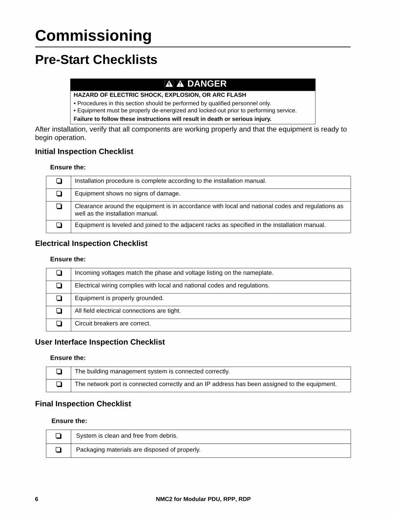
After installation, verify that all components are working properly and that the equipment is ready to begin operation.
Initial Inspection Checklist
Electrical Inspection Checklist
of
User Interface Inspection Checklist
Final Inspection Checklist
DANGERHAZARD OF ELECTRIC SHOCK, EXPLOSION, OR ARC FLASH
• Procedures in this section should be performed by qualified personnel only.• Equipment must be properly de-energized and locked-out prior to performing service.
Failure to follow these instructions will result in death or serious injury.
Ensure the:
Installation procedure is complete according to the installation manual.
Equipment shows no signs of damage.
Clearance around the equipment is in accordance with local and national codes and regulations as well as the installation manual.
Equipment is leveled and joined to the adjacent racks as specified in the installation manual.
Ensure the:
Incoming voltages match the phase and voltage listing on the nameplate.
Electrical wiring complies with local and national codes and regulations.
Equipment is properly grounded.
All field electrical connections are tight.
Circuit breakers are correct.
Ensure the:
The building management system is connected correctly.
The network port is connected correctly and an IP address has been assigned to the equipment.
Ensure the:
System is clean and free from debris.
Packaging materials are disposed of properly.
NMC2 for Modular PDU, RPP, RDP6

Start-up Inspection Checklist
.
DANGERHAZARD OF ELECTRIC SHOCK, EXPLOSION, OR ARC FLASH
Wear appropriate personal protective equipment (PPE) when checking hazardous voltages.
Failure to follow these instructions will result in death or serious injury.
Verify that the PDU is in Total Power OFF mode. All circuit breakers and modules are OFF.
Set all modules that will be used to ON
1. Power Up the PDU.2. Make sure the incoming power circuit breaker is set to ON.3. If applicable, set the Subfeed circuit breaker to ON.
Verify that the display interface is working properly.
Verify through the display interface that the PDU sees the correct number of power modules.
Using a phase rotation meter, verify phase rotation.
Resolve any unexpected alarms.
Configure the date and time through the display interface.
Review the Event Log. Check for abnormalities in the log. Resolve any abnormalities in the log. Clear the Event Log when you are finished.
7 NMC2 for Modular PDU, RPP, RDP

Operation
Display Interface
Navigate the display interface
Selector arrow. Press the UP or DOWN arrow key to move the selector arrow to a menu option or setting. Press the ENTER key to view the selected screen or modify the setting.
Continue arrows. Indicate that additional screens are available on a menu or status screen. Press the UP or DOWN arrow key to view the additional items.
Input arrows. Input arrows next to a selected setting indicate that the setting can be modified by pressing the UP or DOWN arrow key. Press the ENTER key to save the change or the ESC key to cancel.
Press the UP or DOWN arrow key to: a. navigate the selector arrow through the menu promptsb. change target item c. edit a text string. Press the UP or DOWN arrow key to change the character in the text string. Press ENTER to confirm and advance to the next character.
NORMAL LED When green, no alarms are present.
CHECK LOG LED When green, a new event has been added to the log.
WARNING LED When yellow, a warning alarm exists.
CRITICAL LED When red, there are one or more critical alarms in the system.
LCD SCREENDisplays alarms, status data, instructional help, and configuration items.
UP AND DOWN KEYS
Scrolls through menu items.
ENTER Opens menu items and confirms changes to system parameters.
HELP Opens context-sensitive help.
ESC Returns to previous screen.
ESC
?
Normal
CheckLog
Warning
Critical
NMC2 for Modular PDU, RPP, RDP8

Top dynamic display
Overview Screens When the system is running, the display will scroll through screens showing status information of the PDU and any active alarms.
Press the ENTER key to move from the Overview Screens to the Main Menu Screen.
Main Menu Screen
Use the Main Menu Screen to operate, configure, and monitor the system through the sub menu screens: Modules, Totals, Alarms, Log, Admin, and Help.
NOTE: 1. If the display interface is inactive for the time configured for the screen timeout,
the display will return to the scrolling status screens. 2. Pressing the UP arrow key when the selector arrow is at the first item of the main menu will take you to the last item on the menu.
Password protection
Certain screens can be configured to require a predefined password to allow access to those screens. Pressing the ENTER key after selecting a protected screen will result in the user being prompted for the password.
Active Alarms: 1 of 15
With Metering Board[1.6]
Overview Screens (No active alarms)
No Active Alarms
System Date/Time:01/09/2012 10:37:01
Output VoltageL1: 00V L1-2: 0VL2: 00V L2-3: 0V
Communication Lost
Overview screen Alarm Shown
Out Amps kWL1: 0.0 0.00L2: 0.0 0.00L3: 0.0 0.00 L3: 00V L3-1: 0V
Modules Admin
Alarms Totals Help Log
Main Menu Screen
Incorrect Password: Press any key to Try again...
Enter Password: *****
9 NMC2 for Modular PDU, RPP, RDP

Menu tree
The menu tree provides a quick overview of the functions and views you can access.
Modules
Main Menu
Overview Screen
Log
Admin
Help
Circuit Config
Module View
Electrical Cfg
Individual Load Cfg
Mass Configuration
Reset DefaultsCkt
Threshold Values
Threshold Enable
Breaker Position
Local Interface
Date & Time
Manufacturer Data
Network Setup
Device ID Device Name
Display Behavior
Current & Power
Percent Loading
Energy Usage
Module: 00 of 00
Status: Normal/Critical
Circuit Details
About This Module
Module Mfg Info
Cable Details
Breaker Ratings
Factory Defaults
Firmware Upgrade
Alarm Beeper: On/Off
Configure Modbus
Local Password
pd
x087
2b
Serial
TCP
Target ID: 000
Baud Rate: 9600/19200
Port: 00502
Access: Enabled/Disabled
Access: Enabled/Disabled
Total Load Status
Total Load by Phase
Volt-Meter
Total Load Summary
Total Output Current
Voltages/Frequency
Alarms
All Active Alarms
Active by Severity
Active by Type
NMC2 for Modular PDU, RPP, RDP10

Modules SubmenuView Module status
Module: 00 of 00Status: Critical Circuit Details About This Module
Module 00: Cable 0:>Cable 1: Normal>Cable 2: Critical>Cable 3: Normal
Module 00, Cable 0:Name:Circuit (Name)Power: 00.0 kW
Mod 00, Breakers:L1: ClosedL2: OpenL3: Closed
Mod 00, Cable 0:L1: 0.0A 0.0%L2: 0.0A 0.0% L3: 0.0A 0.0%
One-cord Modules
Three-cord Modules
Modules Admin
Alarms Totals Help Log
Module ViewLoad/Energy MeterCircuit Config
Select Modules on the Main Menu Screen and press ENTER. At the next screen, select Module View and press ENTER.
Press ENTER at the Module number. Scroll through the module list to the specific module and press ENTER.
To view more information about the module, select Circuit Details and press ENTER.
For 3-cord modules, select the relevant cable and press ENTER.
Scroll through the three status screens for information on the specific Power Distribution Module.
11 NMC2 for Modular PDU, RPP, RDP

View Power Distribution Module information
Select Modules on the Main Menu Screen and press ENTER. On the next screen, select Module View and press ENTER.
Press ENTER at the Module number. Scroll through the list of modules to the specific module and press ENTER.
Select About This Module and press ENTER.
The module you chose is shown in this submenu.Select and press ENTER to view: Module Mfg Info Cable Details Breaker Ratings
Module: 00 Module Mfg Info Cable Details Breaker Ratings
Module 00 Info:Model: xxxxxxxxxx
Mod 00, Cable: 0 of 0Length: 0.0ft (0.0m)Connector: IEC309-3WVoltages 400V
Mod: 00, Cable: 0 of 0Breaker Ratings:L1:0.0A L2:0.0A L3:0.0A
Module: 00 of 00Status: Normal Circuit Details About This Module
S/N: xxxxxxxxxxxxMfg Date: dd/mm/yyyy
Modules Admin
Alarms Totals Help Log
Module: 00 of 00Status: Critical Circuit Details About This Module
Module ViewLoad/Energy MeterCircuit Config
NMC2 for Modular PDU, RPP, RDP12

View circuit status information
Use the Load/Energy screens to view status information on a circuit level and the data is grouped by output cable. Scroll through the list to the specific circuit. The circuit names are listed for identification.
Refer to “Set the name and location of the circuits” on page 17 for information on how to set the circuit name.
Select Modules on the Main Menu Screen and press ENTER.
Select Load/Energy Meter on the submenu screen and press ENTER.
Select from the Circuit Loading submenu: Current & Power Percent Loading Energy Usage (kWh) Press ENTER at the Reset prompt to reset the kWh registration to zero and change the reset date to the current date.
View load status
Select Totals on the Main Menu Screen and press ENTER.
Select Total Load Status on the submenu and press ENTER.
Status can be Normal, Warning, or Critical. The total power factor and total load is shown in kW and kVA.
Circuit Loading: Current & Power Percent Loading Energy Usage
Mod: 00 Cable: 0 of 0 Circuit (Name)L1:0A L2:0A L3:0A
Mod 00, Cable: 0 of 0L1: 0.0A 0.0%L2: 0.0A 0.0%L3: 0.0A 0.0%
Mod: 00 Cable: 0 of 0 Circuit (Name)Energy: 0000000.0 kWh
Total Power: 0.00kW Reset: mm/dd/yyyy
Modules Admin Totals Help
LogAlarms
Module ViewLoad/Energy MeterCircuit Config
Modules Admin
Alarms Totals Help Log
Total Load StatusTotal Load by PhaseVolt-Meter
Total Load Summary
kVA: 000.0 PF: 0.00
Status: NormalkW: 000.0
13 NMC2 for Modular PDU, RPP, RDP

View total load by phase
Select Totals on the Main Menu Screen and press ENTER.
Select Total Load by Phase on the submenu and press ENTER.
View total output current and power for each phase. High!, Low!, Min!, or Max! indicates a reading above or below the threshold level.
View output voltages
Select Totals on the Main Menu Screen and press ENTER.
Select Volt-Meter on the submenu and press ENTER.
The Voltage Screen shows the output voltages for the three phases and the phase-to-phase voltages.
Modules Admin
Alarms Totals Help Log
Total Load StatusTotal Load by PhaseVolt-Meter
Total Output Current
L3: 000A 000%
L1: 000A 000% L2: 000A 000% high!
KVA kW PF
L3: 00.0 00.0 0.00
L1: 00.0 00.0 0.00 L2: 00.0 00.0 0.00
Modules Admin
Alarms Totals Help Log
Total Load StatusTotal Load by PhaseVolt-Meter
Voltage Freq: 60.0
L3: 0.0 L3-1: 0.0
L1: 0.0 L1-2: 0.0L2: 0.0 L2-3: 0.0
NMC2 for Modular PDU, RPP, RDP14

View the log Modules Admin Totals Help AlarmsLog
View New Log ItemsView Entire LogClear Entire Log
Log Item: 00 of 00mm/dd/yy hh:mm:ssAlarm Description
The log saves information every time a change in the PDU is detected. Alarms and events are recorded in the log and displayed as an active alarm. Status changes are only displayed in the log, and will not display as an active alarm. Viewing the log will clear the Check Log LED.
Select Log on the Main Menu Screen, and press ENTER.
Choose to view recently logged items or the entire log.
Use the arrow keys to scroll through the list of events. Press the ENTER key to view the date and time of a specific event.
Clear the log
Select Log on the Main Menu Screen, and press ENTER.
Select Clear Entire Log and press ENTER.
Select Yes and press ENTER to clear the entire log, or No to return to the Main Menu Screen.
Totals Help
View New Log ItemsView Entire LogClear Entire Log
Confirm: Clear Entire Log? NO, ABORT YES, Clear Log
Modules Admin
Log Alarms
15 NMC2 for Modular PDU, RPP, RDP

View the list of active alarms
The alarm menu lists all active alarms in the PDU. When an alarm is triggered, the PDU will create an alarm and the LEDs on the front panel will illuminate to signify that an alarm has been set.
From the Main Menu Screen, select Alarms.
View all alarms, or alarms by severity or type.Use the UP and DOWN arrow keys to scroll through the list.
All Active Alarms Active by Severity Active by typePress the ENTER key at the selected alarm to view the date and time of a specific alarm.
All Active AlarmsActive by SeverityActive by Type
Modules Admin Totals Help Log Alarms
No Active Alarms
System Date/Time:
View Active Alarms:Distribution (0)
View Active Alarms:Warning (0)Critical (0)
mm/dd/yyyy hh:m:ss
NMC2 for Modular PDU, RPP, RDP16

Configuration
Settings
Mode: Fixed IP AddrStatus: +Up
IP:xxx.xxx.xxx.xxx
Network SetupLocal InterfaceDate & TimeDevice ID
SM:xxx.xxx.xxx.xxx
MAC Address:GW:xxx.xxx.xxx.xxx
xx xx xx xx xx xx
Modules Admin Totals Help Log AlarmsSet up the network
Select Admin on the Main Menu Screen, and press ENTER.
Select Network Setup and press ENTER.
Mode choices are DHCP Only or BOOTP Only to set the IP-address and subnet mask for the system) or Fixed IP Address.
Press the continue arrow to set the Gateway address.The MAC address can be viewed on this screen.
Set the name and location of the circuitsModules Admin Totals Help AlarmsLog
Individual Load CfgMass ConfigurationReset Ckt Defaults
Circuit NameMod: xx Cable: 0 of 0
Name/LocationAlarm Configuration
Name: Circuit NameMxx, Cable y:
Location: Circuit Location
Electrical Config
Module ViewLoad/Energy MeterCircuit Config
Select Modules on the Main Menu Screen, and press ENTER.
Select Circuit Config on the submenu, and press ENTER.
Select Individual Load Cfg and press ENTER.
Select Name/Location and press ENTER.
Change the settings for circuit name and circuit location. Use the UP and DOWN arrow keys to select a character, press ENTER to confirm, and go to the next character.
17 NMC2 for Modular PDU, RPP, RDP

Set individual alarm thresholds
The Individual Load Cfg screens are used to set the alarm thresholds for a single Power Distribution Module.
Select Modules on the Main Menu Screen, and press ENTER.
Select Circuit Config on the submenu screen, and press ENTER.
Select Individual Load Cfg and press ENTER.
In the next submenu, scroll to the desired module. Press ENTER to select a module.
After the module has been selected, scroll to Alarm Configuration and press ENTER.
The selections for Alarm Configuration are: Alarms: Enable or disable. Alarm Thresholds: Change the settings. Reset to defaults: Reset to factory defaults.
Individual Load CfgMass ConfigurationReset Ckt Defaults
Circuit NameMod: 00, Cable: 0 of 0
Name/Location Alarm Configuration
Modules Admin Totals Help
Log Alarms
Module ViewLoad/Energy MeterCircuit Config
Electrical Config
Circuit NameMod: 00, Cable: 0 of 0
Name/Location Alarm Configuration
Alarms: Enabled/DisabledMod: 00, Cable 0:
Alarm ThresholdsReset to defaults
What do you want to
Mod 00 of Cable 0:All of Module 00
Warning ThresholdsMod: 00, Cable 0:
Critical ThresholdsPosition Alarms
reset to defaults?Warning ThresholdsMod: 00, Cable 0:
High: 00% [0.0 A]Alarm: Enabled
Warning ThresholdsMod: 00, Cable 0:
Low: 00% [0.6 A]Alarm: Enabled
Alarms: EnabledMod: 00, Cable 0:
Alarm Thresholds Reset to defaults
NMC2 for Modular PDU, RPP, RDP18

Set alarm thresholds for all Modules in the PDU
Select Modules on the Main Menu Screen, and press ENTER.
Select Circuit Config on the submenu screen, and press ENTER.
Select Mass Configuration and press ENTER.
Change the settings forThreshold Values:
Select the maximumand minimum valuesthat should generate an alarm.
Threshold Enable:Enable or disable the alarms for the different settings.
Breaker Position: Enable or disable alarms when a breaker is opened.
Select Apply to All and press ENTER to confirm your changes.
Set and change the password settings
Network SetupLocal InterfaceDate & TimeDevice ID
Local PasswordDisplay BehaviorAlarm Beeper: Off
Password: xxxxxTimeout: 10 minInvalidate NOW
Modules Admin Totals Help
Log AlarmsSet, change or set the time lock on password-protected
screens. Set the time limit before the display will lock, and a password will be required to make any changes.
Select Admin on the Main Menu screen and press ENTER.
Select Local Interface and press ENTER.
Select Local Password and press ENTER.
Select Password and enter the new password. Use the UP and DOWN arrow keys to select a character and press ENTER to confirm and go to the next character.
Individual Load Cfg Mass Configuration Reset Ckt Defaults
Breaker PositionAlarms: Enabled
Alarms: OFF Min: ON High: OFF Low: OFF Max: OFF Apply to All
Pick Alarm Limits: Min: xx% Hi: xx% Low: xx% Max: xx%
Threshold ValuesMass Configuration:
Threshold Enable Breaker Position
Apply to All Apply to All
Electrical Config
Modules Admin Totals Help
Log Alarms
Module ViewLoad/Energy MeterCircuit Config
19 NMC2 for Modular PDU, RPP, RDP

Change the display settings
Select Admin on the Main Menu screen and press ENTER.
Select Local Interface and press ENTER.
Select Display Behavior and press ENTER.
From this screen, change the settings for:a. Contrast - setting from 00 to 07 b. Key Click - Off/On c. Beeper Volume - Off/Low/Med/Highd. Check Log Light - Info/Warning/Critical/Disable
Change date and time
Select Admin on the Main Menu screen and press ENTER.
Select Date & Time and press ENTER.
The date format, date, and time can be changed from this screen.
Network SetupLocal InterfaceDate & TimeDevice ID
Local PasswordDisplay BehaviorAlarm Beeper: Off
Contrast: 0Key Click: OffBeeper Volume: Off
Check Log Light
Modules Admin Totals Help
Log Alarms
Network SetupLocal InterfaceDate & TimeDevice ID
Mode: ManualFormat:Date: xx-xxx-xx
Time: xx:xx:xx
Modules Admin Totals Help
Log Alarms
NMC2 for Modular PDU, RPP, RDP20

Modbus ConfigurationModbus Serial Configuration
Manufacturer DataFactory DefaultsFirmware UpgradeConfigure Modbus
TCPSerial
Access: DisabledTarget ID: 001Baud Rate: 9600
Modules Admin Totals Help
Log Alarms
Configure Modbus Serial through the Display Interface.
Path: Main > Admin > Configure Modbus > Serial
Use the Serial menu to set up communications between the equipment and the building management system.
Access: Enable or disable Modbus Serial
Target ID: Each Modbus device must have a unique target identification number. Enter a unique number, ranging from 1 to 247, for this unit.
Baud Rate: Choose either 9600 bps or 19200 bps.
Modbus communication is available at the console port (RS232 DB-9 connector).
Note: An RS232 to RS485 converter (not provided) must be used to connect to a building management system.
To communicate RS-232 to the RPP/RDP through the console port, the RS232 to RS485 converter must be configured as a DTE device with Send Data Control rather than RTS control (most converters are DCE - some can be ordered as DTE). Some devices like the Omega Model 285 Superverter support DCE/DTE selection with a switch. Other devices such as those produced by B&B Electronics require a zero ohm resistor re-position to configure as a DCE device - see the device data sheet for details. RTS or SD selection is generally accomplished with a jumper. An appropriate RS-232 cable like the APC 940-0024D is also required.
The console port can be configured to run at either 9600 or 19200 baud. This must match the Building Management System or Modbus network transfer rate.
Most serial converters are capable of either 4-wire or 2-wire modbus connections. The unit is designed to handle 2-wire, half-duplex communication. For a 2-wire, half-duplex connection, jumper connectors should be placed between R+ & T+, and R- & T-. Then the modbus + wire is connected to R+/T+ and the - wire is connected to R-/T-. Some converters like the B&B Electronics 4850T9L offer dip switches to accomplish the jumper connections.
Note: All RS232 to RS485 converters tested relied on a power supply that plugs into 110V AC wall receptacle.Note: There is a known modbus polarity labeling ambiguity between converters, so if the modbus communication isn’t successful, try reversing the 2-wire connection.
21 NMC2 for Modular PDU, RPP, RDP

Modbus TCP Configuration
Configure Modbus TCP through the Display Interface.
Path: Main > Admin > Configure Modbus > TCP
Use the TCP menu to set up communications between the equipment and the building management system through TCP.
Status: Enable or disable Modbus TCP to view the device through your building management service’s interface.
Port: Each Modbus TCP must have a unique target TCP port number. Enter a unique number, ranging from 502, 5000 to 32768.
Press ENTER, the display interface will navigate to the reboot page to save your settings.
Manufacturer DataFactory DefaultsFirmware UpgradeConfigure Modbus
TCPSerial
Status: DisabledPort: 502
Modules Admin Totals Help
Log Alarms
Reboot needed for this change. OK?
NO, Revert, YES, Reboot Now
NMC2 for Modular PDU, RPP, RDP22

Network Management Configuration
Overview NOTE: For complete Network Management Card setup instructions, see the online User Guide at www.apc.com.
Connections
Make the connection to the PDU: A Cat-5 cable is plugged into the bottom RJ-45 connector on the back of the unit. Connect the other end of the cable to a local computer or a network hub. Do not use the top RJ-45 connector above the serial port .
A serial cable can be connected at the serial port . Connect the other end to a local computer.
Initial setup
You must configure the following three TCP/IP settings before the Modular PDU can operate on a network:
• IP address of the Modular PDU
• Subnet mask
• Default gatewayIf a default gateway is unavailable, use the IP address of a computer (that is usually running) located on the same subnet as the NMC. The NMC uses the default gateway to test the network when traffic is light.NOTE: Do not use the loopback address as the default gateway address for the Network Management Card. You will lose communication with the equipment. Doing so will disable the card and require you to reset TCP/IP settings to their defaults using a local serial login.
TCP/IP configuration methods
Use one of the following methods to define the basic TCP/IP settings needed by the Network Management Card.
• APC Device IP Configuration Wizard
• BOOTP or DHCP server
• Networked computer
pd
x087
3a
23 NMC2 for Modular PDU, RPP, RDP

Device IP Configuration Wizard
The Wizard runs on Microsoft Windows 2000, Windows 2003, and Windows XP operating systems. The Device IP Configuration Wizard configures the IP address, subnet mask, and default gateway of one or more NMCs. You can use the Wizard in either of the following ways:
• Remotely over your TCP/IP network to discover and configure unconfigured NMCs on the same network segment as the computer running the Wizard.
• Through a direct connection from a serial port of your computer to the PDU to configure or reconfigure it.
Installation
Install the Wizard from a downloaded executable file:
1. Go to www.apc.com/tools/download.
2. Download the Device IP Configuration Wizard.
3. Run the executable file in the folder in which it was downloaded.
Launch the Wizard
The installation creates a shortcut link in the Start menu to launch the Wizard. Most software firewalls must be temporarily disabled for the Wizard to discover unconfigured NMCs.
Supported Web browsers
Use Microsoft® Internet Explorer (IE) 7.x and higher (Windows operating systems) or Mozilla Firefox 3.0.6 or higher (all operating systems) to access the NMC through its Web interface. Other commonly available browsers may work but have not been fully tested by Schneider Electric. The NMC cannot work with a proxy server. Before using a Web browser to access its Web interface, do one of the following:
• Configure the Web browser to disable the use of a proxy server for the NMC.
• Configure the proxy server so that it does not proxy the specific IP address of the NMC.
Network management features
These applications and utilities work with a Modular PDU that connects to the network through its Network Management Card:
• StruxureWare—Provide enterprise-level power management and management of agents, PDUs, information controllers, and environmental monitors
• PowerNet® Management Information Base (MIB) with a standard MIB browser—Perform SNMP SETs and GETs and to use SNMP traps
• Device IP Configuration Wizard—Configure the basic settings of one or more NMCs over the network
• Security Wizard—Create the components needed for high security for the NMC when using Secure Sockets Layer (SSL) and related protocols and encryption routines
NMC2 for Modular PDU, RPP, RDP24

Log OnOverview
Use the DNS name or System IP address of the unit for the URL address of the Web interface. Use your case-sensitive user name and password to log on.
The default user password for three account types is apc. The default user name differs by account type:
• apc for the Super User
• device for a Device User
• readonly for a Read-Only User
The Super User or an Administrator created by the Super User should define the user names, passwords, and other account characteristics for the lower tier users.
If you are using HTTPS (SSL/TSL) as your access protocol, your logon credentials are compared with information in a server certificate. If the certificate was created with the APC Security Wizard, and an IP address was specified as the common name in the certificate, you must use an IP address to log on to the unit. If a DNS name was specified as the common name on the certificate, you must use a DNS name to log on.
URL address formats
Type the DNS name or IP address of the unit in the URL address field of the Web browser and press ENTER. When you specify a non-default Web server port in Internet Explorer, you must include http:// or https:// in the URL.
Common browser error messages at log-on
URL format examples
• For a DNS name of Web1:
– http://Web1 if HTTP is your access mode
– https://Web1 if HTTPS (HTTP with SSL) is your access mode
• For a System IP address of 139.225.6.133 and the default Web server port (80):
– http://139.225.6.133 if HTTP is your access mode
– https//139.225.6.133 if HTTPS (HTTP with SSL) is your access mode
• For a System IP address of 139.225.6.133 and a non-default Web server port (5000):
– http://139.225.6.133:5000 if HTTP is your access mode
– https://139.225.6.133:5000 if HTTPS (HTTP with SSL) is your access mode
For a System IPv6 address of 2001:db8:1::2c0:b7ff:fe00:1100 and a non-default Web server port (5000):http://[2001:db8:1::2c0:b7ff:fe00:1100]:5000 if HTTP is your access mode
Error Message Browser Cause of the Error
“This page cannot be displayed.” Internet Explorer Web access is disabled, or the URL was not correct
“Unable to connect.” Firefox
25 NMC2 for Modular PDU, RPP, RDP

User Account OverviewThe Modular Power Distribution Unit arrives configured with three User Types, as well as associated User Names:
• Super User (User Name: apc)
• Device (User Name: device)
• Read-Only (User Name: readonly).
The initial default password for each of these is apc. All levels of access require user name and password permissions.
Both user name and password are case-sensitive, and have a 64 byte maximum, supporting up to 64 ASCII characters; less for multi-byte languages.
The Super User can define additional user accounts, as well as set other variables for the additional users. It is generally recommended that non-default user name and passwords be set.
NOTE: The Super User cannot be renamed or deleted, but it can be disabled. It is recommended that the Super User account is disabled once any additional Administrator accounts are created. Make sure that there is at least one Administrator account enabled before the Super User account is disabled.
In order to manage User settings from the web browser (accessed by entering the NMC IP address into the address bar), navigate to Configuration > Security > Local Users > Management.
• Click on Add User
The User types which can be added are:
• Administrator: The Administrator user has full access just as the Super User does, but this user type can be deleted. NOTE: A Super User account must be enabled before all administrator accounts are deleted or disabled.
• Device: The Device user has read-write access to the device-related menus only. The Administrator can enable or disable the Device user account.
• Read-Only: The Read-Only User account has read-only access, through the Web interface, to view status but not to control a device or change any configured value. The Administrator can enable or disable the Read-Only user account.
• Network-Only: The Network-Only user has read-write access to the network-related menus only. The Administrator can enable or disable the Network-Only user account.
NMC2 for Modular PDU, RPP, RDP26

Watchdog FeaturesWatchdog mechanisms detect internal problems. After a restart, a System: Warmstart event is recorded in the event log.
Network interface watchdog mechanism
Watchdog mechanisms protect the NMC from becoming inaccessible over the network. If it does not receive any network traffic for 9.5 minutes, it assumes there is a problem with its interface and restarts.
Resetting the network timer
To ensure the NMC does not restart if the network is quiet for 9.5 minutes, it attempts to contact the default gateway every 4.5 minutes. The gateway response resets the 9.5-minute timer. If your application does not require or have a gateway, specify the IP address of a computer that is running on the network most of the time and is on the same subnet. The network traffic of that computer will restart the 9.5-minute timer frequently enough to prevent the NMC from restarting.
27 NMC2 for Modular PDU, RPP, RDP

NMC2 for Modular PDU, RPP, RDP28
Recover from a Lost Password You can use a local computer (a computer connected to your power distribution unit through the serial port) to access the command line interface.
1. At the local computer, select a serial port, and disable any service that uses it. 2. Connect the provided serial cable to the selected serial port on the local computer and
the other end of the cable to the serial port on the power distribution unit.3. Open a terminal program (such as HyperTerminal®) and configure the port for:
9600 bps, 8 data bits, no parity, 1 stop bit, and no flow control.
4. Press ENTER, repeatedly if necessary, to display the User Name prompt. If you are unable to display the User Name prompt, verify the following:
– The serial port is not in use by another application.
– The terminal settings are correct as specified in step 3.
– The correct cable is being used as specified in step 2.
– SCROLL LOCK is not turned on.
5. Press the Reset button on the back of the unit. The Status LED will flash. Press the Reset button a second time while the LED is flashing to reset the user name and password to the default temporarily.
6. Press ENTER as many times as necessary to redisplay the User Name prompt, then use the default, apc, user name and password. (If you take longer than 30 seconds to log on after the User Name prompt is redisplayed, you must repeat step 5 and log on again.)
7. At the Command Console, use the following commands to change the password setting for the Super User account, for which the user name is always apc, and the password is now temporarily apc:
user -n apc -pw yourNewSuperUserPassword
Example: to change the Super User's password to p@ssword type:
user -n apc -pw p@ssword
NOTE: Because the Super User can also reset the password for any account, you can reset other user's passwords as well.Example: to change the password for user bmadmin to p@ssword type:
user -n bmadmin -pw p@ssword
NOTE: Changing user name information is no longer supported via the Command Console. If a user's user name needs to be changed, it must be deleted and re-created. The Super User will also have access now to log in and adjust any other user's password.
8. Type QUIT, EXIT, or BYE to log off. Remember to reconnect any serial cable you may have disconnected, and to restart any service you may have disabled. Return the local computer to its original configuration.
NOTE: Modbus and the Command Console share a common serial port. In some instances, the baud rate may be set to different speeds for other services, i.e. Modbus (19200 bps).

Maintenance
Parts ReplacementDetermine if you need a replacement part
To determine if you need a replacement part, contact Schneider Electric Customer Support and follow the procedure below so that a representative can assist you promptly:
1. The display interface may show additional screens if module replacement is necessary. Press any key to scroll through these lists, record the information, and provide it to the representative.
2. Write down the serial number of the unit so that you will have it easily accessible when you contact Customer Support.
3. If possible, call Customer Support from a telephone that is within reach of the unit so that you can gather and report additional information to the representative.
4. Be prepared to provide a detailed description of the problem. A representative will attempt to help you over the telephone, if possible, or will assign a Return Material Authorization (RMA) number to you. If a module is returned, this RMA number must be clearly printed on the outside of the package.
5. If the unit is within the warranty period, repairs or replacements will be performed free of charge. If it is not within the warranty period, there will be a charge.
6. If the unit is covered by a service contract, have the contract available to provide information to the representative.
Return parts
Contact Customer Support to obtain an (Returned Materials Authorization (RMA) number.
To return a module, pack the module in the original shipping materials, and return it by insured, prepaid carrier. The Customer Support representative will provide the destination address. If you no longer have the original shipping materials, ask the representative about obtaining a new set. Pack the module properly to avoid damage in transit. Never use Styrofoam beads or other loose packaging materials when shipping a module, as the module may settle in transit and become damaged. Enclose a letter in the package with your name, RMA number, address, a copy of the sales receipt, description of the problem, a phone number, and a check as payment (if necessary).
NOTE: Damages sustained in transit are not covered under warranty.
29 NMC2 for Modular PDU, RPP, RDP

NMC2 for Modular PDU, RPP, RDP30
Power Distribution Modules
Factory installed filler plates and slot locks cover each module position.
Before putting the unit into service, the backplane of each module position must be covered with a filler plate or a Power Distribution Module (PDM). All positions must be secured with a slot lock.
Component identification
Slot lock key
Slots (hold modules in place)
Backplane
Filler plate
Module slot lock
Power distribution module
NOTE: Two slot locks are attached together as a pair. The illustration shows the top lock removed from its slot but still attached to the installed lock below it.
DANGERHAZARD OF ELECTRIC SHOCK, EXPLOSION, OR ARC FLASH• Electrical equipment must be installed, operated, serviced, and maintained only by
qualified personnel.• To remove a Power Distribution Module:
1. Turn off all power supplying the equipment and perform appropriate lockout/tagout procedures before installing or removing the Power Distribution Module.OR
2. If a Symmetra PX UPS is providing power to the Modular PDU, place the UPS into battery operation (to reduce fault current) before removing the Power Distribution Module. To place the UPS into battery operation, see the UPS Operation Manual.
Failure to follow these instructions will result in death or serious injury.
NOTICE• Install only Schneider Electric PDMs with matching output voltage.
• Install PDMs starting from the bottom of the panel to avoid cable congestion.
• Save filler plates for future re-use. If a module is removed, a filler plate must be installed to cover the open space.
pdx1
041a
pd
x104
3a

Module Types
Test the Residual Current Device
NOTE: Pushing the test button will open circuit breakers, distributing power to the equipment.
Press the test button and confirm that the Residual Current Device (RCD) and adjacent circuit breaker trip to the OFF position.
Reset the RCD and circuit breaker to normal by pushing the toggle to the ON position.
NOTICE• A ground fault will automatically open the adjacent circuit breaker on PDMs with Residual
Current Devices (RCDs) installed. • PDMs with RCDs are equipped with a test button. Periodic testing of the RCD may be required.
Check local codes for your region.p
dx10
49a
pdx0
304a
pdx0
303a
pdx0
302a
ON position
ON position
PDM – Single and Three phase PDM with RCD (Residual Current Devices) - Three phase
PDM with RCD – Single phase
ON position
PDMs with RCDs
A ground fault will open the adjacent circuit breaker to the OFF position. The fault is indicated by a red strip on the RCD toggle.
The circuit breaker has been closed manually by pushing the toggle to the ON position.
Test button
Test button
pdx0
427a
31 NMC2 for Modular PDU, RPP, RDP

NOTE: Some module circuit breaker styles have circuit breaker handles that will pull all the breakers to the OFF position but can be flipped up to access the individual breakers separately.
pdx0
848b
OFF position ON positions
NMC2 for Modular PDU, RPP, RDP32

Installation
Open the front door of the unit.
Remove the slot lock
Use the key (provided) to remove the slot lock.
Insert the key in the slot lock as shown in the illustration.
Squeeze the sides of the key inward to grasp the slot lock firmly.
Pull the slot lock key out, while squeezing, to extract the lock from the slot.
DANGERHAZARD OF ELECTRIC SHOCK, EXPLOSION, OR ARC FLASH• Electrical equipment must be installed, operated, serviced, and maintained only by
qualified personnel.• To remove a Power Distribution Module:
1. Turn off all power supplying the equipment and perform appropriate lockout/tagout procedures before installing or removing the Power Distribution Module.OR
2. If a Symmetra PX UPS is providing power to the Modular PDU, place the UPS into battery operation (to reduce fault current) before removing the Power Distribution Module. To place the UPS into battery operation, see the UPS Operation Manual.
Failure to follow these instructions will result in death or serious injury.
pdx1
042a
33 NMC2 for Modular PDU, RPP, RDP

Remove the filler plates
Press down on the filler plate clip to release its locking mechanism.
Pull the filler plate along the slot until it is free.
Install a module
Make sure all circuit breakers on the PDM being installed are in the OFF (open) position.
Press the red button to release the latch on the PDM.
Pull open the latch.
pdx1
040a
pdx0
257b
NMC2 for Modular PDU, RPP, RDP34

Slide the PDM into the panel using the top and bottom guide tracks (slots) for that position. Slide the PDM all the way into position. Close the latch to tighten the electrical contacts in the PDM against the backplane.
Feed cable from the PDM through the slot in the roof.
pdx0
299a
pdx0
299b
Horizontal Rack Distribution Panel Vertical Rack Distribution Panel
pdx0
246a
35 NMC2 for Modular PDU, RPP, RDP

Vertical Rack Distribution Panel Only: Leave a minimum of 7 inches (178 mm) of slack in the cable behind the module. The slack is useful in case the module is ever removed or replaced. 10 to 20 inches (254 to 508 mm) is recommended but space restrictions in the PDU and cable diameter size will cause the amount of slack to necessarily vary. When installing PDMs near the top of the panel, feed the cable first, pulling up the slack, and then secure the module to the backplane to avoid cable congestion between the panel and the slot.Use plastic ties to secure loose cable(s) to the enclosure
pdx0
332a
pdx0
300a
NMC2 for Modular PDU, RPP, RDP36

Set the required breakers on the newly installed PDM to the ON (closed) position.
Install filler plates
Install filler plates to properly cover 3-pole panel positions not occupied by a PDM.
Position the filler plate in front of an open PDM location and insert the bottom tab of the filler plate into the slot.
Snap the filler plate into position. Check that the latch is secure.
pdx0
848c
One Circuit Breaker ON All Circuit Breakers ON
pdx1
055a
37 NMC2 for Modular PDU, RPP, RDP

Install a slot lock
NOTE: A slot lock must be installed in each module space whether filled by a module or filler plate.
Press the slot lock into the slots as shown in the illustration.
NOTE: Upon completion of PDM installation, close the door to the PDU.
pdx0
\105
3a
NMC2 for Modular PDU, RPP, RDP38

Connect Module cables
Connect the PDM cable to the appropriate Rack PDU or other equipment.
NOTE: Power can be restored to the PDU following connection of the PDM cables to the load.
Remove a PDM
Reverse the module installation procedure to remove a PDM.
DANGERHAZARD OF ELECTRIC SHOCK, EXPLOSION, OR ARC FLASH
• Electrical equipment must be installed, operated, serviced, and maintained only by qualified personnel.
• To remove a Power Distribution Module:
1. Turn off all power supplying the equipment and perform appropriate lockout/tagout procedures before installing or removing the Power Distribution Module.OR
2. If a Symmetra PX UPS is providing power to the Modular PDU, place the UPS into battery operation (to reduce fault current) before removing the Power Distribution Module. To place the UPS into battery operation, see the UPS Operation Manual.
Failure to follow these instructions will result in death or serious injury.
pdx1
057a
39 NMC2 for Modular PDU, RPP, RDP

Troubleshooting
LED Indicators on PDMs
pdx
1049
a
LED IndicatorsThere are three LEDs on each Power Distribution Module. The LEDs
indicate the following conditions:
• Red: A critical alarm.
• Yellow: A warning alarm
• Green: No alarm.
• Flashing green: The module is being identified by the system.
Status and Alarm Messages
Display Message Detailed Description Corrective Action
High Module Current. The high module current threshold has been exceeded.
Evaluate the threshold setting. Adjust for your situation.
High Subfeed Current. The high subfeed current threshold has been exceeded.
Evaluate the threshold setting. Adjust for your situation.
High Total Output Current The total output current exceeded the high threshold.
Evaluate the threshold setting. Adjust for your situation.
High Output Voltage The output voltage exceeded the high threshold.
Evaluate the threshold setting.Adjust for your situation.
Low Module Current. The low module current threshold has been exceeded.
Evaluate the threshold setting. Adjust for your situation.
Low Subfeed Current. The low subfeed current threshold has been exceeded.
Evaluate the threshold setting. Adjust for your situation.
Low Total Output Current The total output current dropped below the low threshold.
Evaluate the threshold setting. Adjust for your situation.
Low Output Voltage The output voltage dropped below the low threshold.
Evaluate the threshold setting. Adjust for your situation.
Maximum Module Current.
The maximum module current threshold has been exceeded.
Evaluate the threshold setting. Adjust for your situation.
Maximum Subfeed Current.
The maximum subfeed current threshold has been exceeded.
Evaluate the threshold setting. Adjust for your situation.
Max Total Output Current The total output current exceeded the maximum threshold.
Evaluate the threshold setting. Adjust for your situation.
Max Output Voltage The output voltage exceeded the maximum threshold.
Evaluate the threshold setting. Adjust for your situation.
Minimum Module Current. The minimum module current threshold has been exceeded.
Evaluate the threshold setting. Adjust for your situation.
Minimum Subfeed Current.
The minimum subfeed current threshold has been exceeded.
Evaluate the threshold setting. Adjust for your situation.

Modular Distribution Communication.
Communication has been lost with the modular distribution breakers.
Check the communication cables to ensure they are properly connected. Contact Customer Support.
Module Breaker Open. A modular circuit breaker is open.
Check the modular circuit breakers to see if one has overloaded. Replace if necessary.
Output Frequency The output frequency is exceeding the frequency deviation threshold.
Evaluate the threshold setting and the power quality. Adjust the threshold setting to accommodate your situation. Note: Some backup generators do not tightly regulate their output during normal operation and can trigger this alarm.
Subfeed Breaker Open. A subfeed circuit breaker is open.
Check the subfeed circuit breakers to see if one has been over-loaded.
Display Message Detailed Description Corrective Action
41 NMC2 for Modular PDU, RPP, RDP


Worldwide Customer Support
Customer support for this product is available at www.apc.com.
6/2016990-9931-001
© 2016 Schneider Electric. All rights reserved.