operation manual for the authorized specialist -...
TRANSCRIPT

Operation ManualFor the authorized specialist
Oil Duoblock BurnerRPD 30 - 100 L-R / S-R
03/2005 102.873.3388

2
Inhalt
General Information ............................................................. 3Technical Data Sheet .......................................................... 4Burner Construction .......................................................... 10Mounting the Burner to the Boiler ...................................... 11Combustion Air FanDrive Modes ...................................................................... 12Dimensioned Drawing for RPD Burner 20 - 100 ............... 13Burner scheme .................................................................. 15Hydraulic Scheme ............................................................. 17Hydraulic Scheme ............................................................. 18Mounting PositionLeak TestIgnition Gas ConnectionIgnition Burner Type ZT0 ................................................... 20Ignition Gas Solenoid Valve .............................................. 24Oil Connection ................................................................... 25Oil Connection ................................................................... 26Medium pressure screw pumps ........................................ 27Burner Pump AssemblyElectrical Connection ......................................................... 29Return Nozzle Rod DG 75 ................................................. 30Return Nozzle Rod MAT ................................................... 31Throughput Rate CharakteristicsLight Fuel Oil ..................................................................... 32Throughput Rate CharakteristicsHeavy Fuel Oil ................................................................... 40Dimensions of the Mixing Unit ........................................... 49Draw-out and Swing Mechanism ....................................... 50Air Flow AdjustmentOil Flow Adjustment .......................................................... 51Mechanical Compound Controller ..................................... 52Pressure Setting ................................................................ 53Removal and Replacing the Shaft Seal of the Return Flow Nozzle Assembly DG 75 ..................... 54Oil Pressure SwitchAir Pressure Switch ........................................................... 55Setting Pressure Switches and Control System .................................................................. 56Automatic Furnace Controller LAL... / LOK... .................... 57Flame Monitor Sensor Current Measurement ........................................... 58Actuator Type ARIS, WAN 3, 4, 4a, 5 ............................... 59Solenoid Safety Valves ..................................................... 602/2 Way Valve Type MK 15 ............................................... 632/2 Way Valve Type MK 20 ............................................... 65Pipe spring - Glycerine - ManometerBimetal - Pointer - Temperature controller ........................ 67Flushing and Oil Feed Start Thermostat ATH 22 ........................................................... 68Start-up Light Oil ............................................................... 69Start-up Heavy Oil ............................................................. 70Viscosity as a Function of Oil Temperature ....................... 71Oil Start-upBurner ShutdownMeasures in Case of Trouble ............................................ 72Exhaust Gas Test .............................................................. 73SO2-content in Exhaust Gasfrom Light Oil and Heavy Oil Combustion ......................... 74O2, CO2, Lambda Conversion Table ................................ 75O2, CO2, Lambda Conversion Table ................................ 76Trouble Shooting Instructions ............................................ 77
Contents

3
General Information
Important informationThe burners of type RPD 30...100 L/S-E.../R... have been designed for the combustion of natural gas or fuel oil.The burners should be installed and taken into operation by qualified person-nel only who will be responsible for the proper performance of this work in accordance with the applicable regulati-ons and guidelines.
Any repair work on monitors, limiters and automatic furnace controllers and on the other safety facilities are allowed to be done only by the manufacturers themselves or specialists authorized by them. Original parts should only be exchanged by a duly qualified specia-list.
Standards and regulationsThe following standards should be observed in the interest of a safe, easy-on-the-environment and energy-saving operation of the burner:
According to EN 267, the user must be instructed in the operation of the burner and according to DIN 4755, the user must be introducted in to gas firing system.
For the installation of an oil furnace system, care should be taken to observe DIN 4755, TRbF (Technical Regulation on Combustible Liquids) and the local furnace construction regulati-ons applicable in the country.
Start-upThe furnace system should be started initially by the installer, manufacturer or other specialized personnel. Prior to taking the furnace system into opera-tion, make a test of all automatic con-trol, safety and control facilities for proper functional order and check them for correct setting if of adjustable type. Furthermore, check the control circuits, fans, etc. for proper fuse rating, and whether suitable precautions have been taken to prevent accidental contact.
Inspection and Maintenance The furnace system should be inspec-ted and serviced at least once a year by an authorized specialist of the installer to ensure its proper functional order, operational safety and energy-saving operation. Check the system for absence of leaks and functional order. For the combustion analysis proceed as described in the section entitled „Exhaust Gas Test“. It is recommended to conclude a maintenance agreement to this effect.
WarrantyManufacturer will not accept any war-ranty if the operating instructions have not been duly observed in the start-up and maintenance of the burner and damages have been caused by impro-per installation, incorrect adjustment, unauthorized interference or operating errors.
Burner installation and accessories
Boiler liningThe boiler lining should be made of heat-resistant materials (temperature resistance >1400°C). Take care that the burner flame tube is covered by the boiler lining over its full length.The open space between the burner flame tube and the boiler lining should be packed with mineral wool.
Checks prior to burner installation
1 Check the mixing ignition unit according to the boiler output.
2 Oil nozzles and mixing ignition unit.
3 Pilot burner setting.
4 See dimensioned drawing for set-ting dimensions of mixing ignition unit.
5 Check the air cylinder for proper function (possible damage in transport).
6 Check the air damper setting according to flame pattern and fur-nace chamber geometry.
EN 267/ DIN 4787
Oil atomizer burners
VDE 0116 Electrical Equipment of furnace

4
Technical Data Sheet
Duoblock Oil Burner
Feld52:RPD 30 / 40 / 50 L-R / S-R
6215
8230
11160
1130901
1400
0
2000
4000
6000
8000
10000
12000
RPD 30 RPD 40 RPD 50
kW
Technical Data
Fuel flow rate (light oil)
Operating mode
Fuel type
Automatic burner controller
Flame sensor
Ignition burner
Ignition transformer
Pump output at 35 bar
Oil connection
Nozzle rod
Nozzle
Actuator
Weight
Pressure loss in mixing unit
Burner output
Output range
Art. Nr.: 102.876.773202/02
MAT oil control block
1130 - 6215 kW
RPD 30
96 - 524 kg/h
fully modulating
Light oil / heavy oil
LAL 2., LOK 16 or other approved models
QRB 3, RAR 7 or other approved models
MAT / Hegwein ZNVL (ZT0)
D-52 L5 KVZ112 K5
1200 l/h
SRB 19000/30
R 3/4" / 22 mm
MAT / DG 75
MAT - MK 27
WAN 4
300 kg
30 mbar or according to diagram
(MAT ignition burner) (Hegwein ignition burner)
901 - 8230 kW
RPD 40
76 - 694 kg/h
1850 l/h
SRB 19000/40
R 3/4" / 22 mm
MAT / DG 75
MAT - MK 27
WAN 4
350 kg
1400 - 11160 kW
RPD 50
118 - 941 kg/h
2400 l/h
SRB 19000/50
R 3/4" / 22 mm
MAT / DG 75
MAT - MK 27
WAN 4
450 kg
Technical Data Sheet
Duoblock Oil BurnerRPD 30, 40 & 50 L-R / S - R

5
RPD 30, 40 & 50 L-R / S - R
DescriptionDimensions
Operating modeFully automatic pressure jet oil burner, especially designed for high turn down ratios, safety equipment according to EN 267.
Electric designBurner pre-wired and ready to connect. All burner components wired to the bur-ner terminal rail. Burner control box supplied loose for installation in sepa-rate control panel. Separately fitted oil pump assembly.
Combustion airSeparate combustion air blower with stable and pulsation-free characteristics also on appliances with a high flue gas resistance. The combustion air volume is divided into a primary and a secon-
dary stream. The flame shape may be adapted by adjustable twist dampers.
Control systemsoil side : adjustable by means of return flow system with compound controller and spill back nozzle.air side : by means of compound con-troller with adjustable cam discs for pri-mary air (air dampers) and secondary air (air cylinder).
Monitoring systemFlame monitoring by means of flame sensor and tested burner control box . Combustion air monitoring achieved through differential air pressure switch, resp. speed control switch in case of burner with speed control regulation.
IgnitionDirect high voltage spark ignition, 5000 V, by means of an inbuilt ignition burner.
D2
W
D3
22,5 °
B8
X P4
P3
P1
P2
Y
B1
Z
B2
444
RPD 20 - 60
22,5 °
H3
H2
D1
H4 H
1
A1D2
D7
D4
D6
50%
D5
100
%
L6 50%
G
L4 100%
B3 B4 B5
RPD 70 - 100
D2
D3
Gewinde
Länge KStift M
Bohrungen Kesselplatte
B6
15°15°
L1
U
L5
R
RPD A1 B1 B2 B3 B4 B5 B6 B8 D1 D2 D3 D4 D5 D6 D7 G H1 H2 H3 H4 K L1 L4
30 745 78 19 260 375 70 705 416 830 790 385 371 290 323,5 17,5 317 620 373 993 650 30 700 124
40 745 78 19 260 375 70 705 416 830 790 423 409 340 367 17,5 442 620 373 993 650 30 700 95
50 950 78 19 315 375 70 760 535 1030 990 470 456 380 410 17,5 370 675 475 1150 740 30 770 110
RPD L5 L6 M P1 P2 P3 P4 R T T1 T2 T3 U V W X Y Z LB C FI F2 F3
30 1350 62 12 580 670 320 410 1265 - - - - 22x1,5 - 248 4x92 5x126 10 - - - - -
40 1425 50 12 580 670 320 410 1265 - - - - 22x1,5 - 248 4x92 5x126 10 - - - - -
50 1620 55 12 740 830 416 506 1743 - - - - 22x1,5 - 319 3x152 5x156 10 - - - - -
set screw Mlength K
Details of boiler front plate
6
Technical Data Sheet
Duoblock Oil Burner
Feld52:RPD 60 / 70 / 80 L-R / S-R
15418
20636
31938
23723620
5930
0
5000
10000
15000
20000
25000
30000
35000
RPD 60 RPD 70 RPD 80
kW
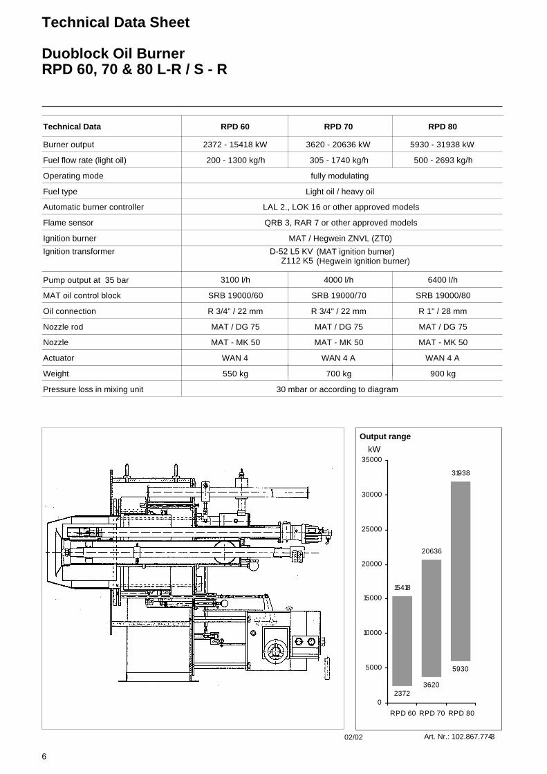
Technical Data
Fuel flow rate (light oil)
Operating mode
Fuel type
Automatic burner controller
Flame sensor
Ignition burner
Ignition transformer
Pump output at 35 bar
Oil connection
Nozzle rod
Nozzle
Actuator
Weight
Pressure loss in mixing unit
Burner output
Output range
Art. Nr.: 102.867.774302/02
MAT oil control block
2372 - 15418 kW
RPD 60
200 - 1300 kg/h
fully modulating
Light oil / heavy oil
LAL 2., LOK 16 or other approved models
QRB 3, RAR 7 or other approved models
MAT / Hegwein ZNVL (ZT0)
D-52 L5 KVZ112 K5
3100 l/h
SRB 19000/60
R 3/4" / 22 mm
MAT / DG 75
MAT - MK 50
WAN 4
550 kg
30 mbar or according to diagram
(MAT ignition burner) (Hegwein ignition burner)
3620 - 20636 kW
RPD 70
305 - 1740 kg/h
4000 l/h
SRB 19000/70
R 3/4" / 22 mm
MAT / DG 75
MAT - MK 50
WAN 4 A
700 kg
5930 - 31938 kW
RPD 80
500 - 2693 kg/h
6400 l/h
SRB 19000/80
R 1" / 28 mm
MAT / DG 75
MAT - MK 50
WAN 4 A
900 kg
Technical Data Sheet
Duoblock Oil BurnerRPD 60, 70 & 80 L-R / S - R

7
G
P4
P3X
P1
P2
YZ
B2B1444
RPD 20 - 60
H2
H3
D1
H1
H4
D7A1D2
D4
D5
100
%
D6
50%
L6 50%
L4 100%
B3 B4 B5W
RPD 70 - 100
D2 D2
Gewinde
Länge KStift M
D3 D3
Bohrungen Kesselplatte
B6
22,5 ° 22,5 °
B8
15°15°
L5L1
U
R
RPD A1 B1 B2 B3 B4 B5 B6 B8 D1 D2 D3 D4 D5 D6 D7 G H1 H2 H3 H4 K L1 L4
60 994 78 19 315 375 70 760 622 1080 1040 520 506 420 455,5 18 312 700 497 1197 825 30 735 125
70 1160 78 19 315 375 75 765 731 1240 1200 640 626 520 565,5 18 469 780 580 1360 900 30 740 170
80 1350 75 19 315 375 75 765 860 1450 1400 740 710 597 646 18 600 820 675 1495 1000 30 700 185
RPD L5 L6 M P1 P2 P3 P4 R T T1 T2 T3 U V W X Y Z LB C FI F2 F3
60 1695 62,5 12 750 840 470 560 1760 - - - - 22x1,5 - 379 4x129 5x160 10 - - - - -
70 1995 85 12 936 1026 600 690 2010 - - - - 28x1,5 - 410 5x128 7x140 10 - - - - -
80 2285 92 12 1102 1192 700 790 2320 - - - - 28x1,5 - 489 6x125 9x128 10 - - - - -
RPD 60, 70 & 80 L-R / S-R
DescriptionDimensions
Operating modeFully automatic pressure jet oil burner, especially designed for high turn down ratios, safety equipment according to EN 267.
Electric designBurner pre-wired and ready to connect. All burner components wired to the bur-ner terminal rail. Burner control box supplied loose for installation in sepa-rate control panel. Separately fitted oil pump assembly.
Combustion airSeparate combustion air blower with stable and pulsation-free characteristics also on appliances with a high flue gas resistance. The combustion air volume
is divided into a primary and a secon-dary stream. The flame shape may be adapted by adjustable twist dampers.
Control systemsoil side : adjustable by means of return flow system with compound controller and spill back nozzle.air side : by means of compound con-troller with adjustable cam discs for pri-mary air (air dampers) and secondary air (air cylinder).
Monitoring systemFlame monitoring by means of flame sensor and tested burner control box . Combustion air monitoring achieved through differential air pressure switch, resp. speed control switch in case of burner with speed control regulation.
IgnitionDirect high voltage spark ignition, 5000 V, by means of an inbuilt ignition burner.
set screw Mlength K
Details of boiler front plate

8
Technical Data Sheet
Duoblock Oil Burner
Feld52:RPD 90 / 100 L-R / S-R
42000
45000
70008183
0
5000
10000
15000
20000
25000
30000
35000
40000
45000
50000
RPD 90 RPD 100
kW
Technical Data
Fuel flow rate (light oil)
Operating mode
Fuel type
Automatic burner controller
Flame sensor
Ignition burner
Ignition transformer
Pump output at 35 bar
Oil connection
Nozzle rod
Nozzle
Actuator
Weight
Pressure loss in mixing unit
Burner output
Output range
Art. Nr.: 102.867.775402/02
MAT oil control block
7000 - 42000 kW
RPD 90
590 - 3540 kg/h
fully modulating
Light oil / heavy oil
LAL 2., LOK 16 or other approved models
QRB 3, RAR 7 or other approved models
MAT / Hegwein ZNVL (ZT0)
D-52 L5 KVZ112 K5
8900 l/h
SRB 19000/90
R 1" / 28 mm
MAT / DG 75
MAT - MK 50
WAN 5 A
1100 kg
30 mbar or according to diagram
(MAT ignition burner) (Hegwein ignition burner)
8183 - 45000 kW
RPD 100
690 - 3800 kg/h
9500 l/h
SRB 19000/90
R 1" / 28 mm
MAT / DG 75
MAT - MK 50
WAN 5 A
1150 kg
Technical Data Sheet
Duoblock Oil BurnerRPD 90 & 100 L-R / S-R

9
RPD 90 & 100 L-R / S-R
DescriptionDimensions
Operating modeFully automatic pressure jet oil burner, especially designed for high turn down ratios, safety equipment according to EN 267.
Electric designBurner pre-wired and ready to connect. All burner components wired to the bur-ner terminal rail. Burner control box supplied loose for installation in sepa-rate control panel. Separately fitted oil pump assembly.
Combustion airSeparate combustion air blower with stable and pulsation-free characteristics also on appliances with a high flue gas resistance. The combustion air volume
is divided into a primary and a secon-dary stream. The flame shape may be adapted by adjustable twist dampers.
Control systemsoil side : adjustable by means of return flow system with compound controller and spill back nozzle.air side : by means of compound con-troller with adjustable cam discs for pri-mary air (air dampers) and secondary air (air cylinder).
Monitoring systemFlame monitoring by means of flame sensor and tested burner control box . Combustion air monitoring achieved through differential air pressure switch, resp. speed control switch in case of burner with speed control regulation.
IgnitionDirect high voltage spark ignition, 5000 V, by means of an inbuilt ignition burner.
D4
L6 50%
G
L4 100%
RPD 20 - 60
P1
P2
Y
B1444
X
Z
T1 B2
P4
P3H
2
D1
H3
H4
T2
T3
V
D7A1D2
D5
100
%
D6
50%
H1
B3 B4 B5W
15°
D2
D3
15°
B6
D2
Stift MGewinde
Länge K
D3
B8
Bohrungen Kesselplatte
22,5 ° 22,5 °
RPD 70 - 100
U
L1
R
T
L5
RPD A1 B1 B2 B3 B4 B5 B6 B8 D1 D2 D3 D4 D5 D6 D7 G H1 H2 H3 H4 K L1 L4
90 1700 75 3 420 375 75 870 890 1800 1750 883 870 675 - 18 810 905 850 1755 1100 30 745 190
100 1700 75 3 420 375 75 870 890 1800 1750 935 920 830 - 18 810 905 850 1755 1100 30 745 190
RPD L5 L6 M P1 P2 P3 P4 R T T1 T2 T3 U V W X Y Z LB C FI F2 F3
90 2585 - 12 1300 1390 742 832 2720 - - - - 28x1,5 - 494 6x132 10x135 10 - - - - -
100 2585 - 12 1300 1390 742 832 2720 - - - - 28x1,5 - 494 6x132 10x135 10 - - - - -
set screw Mlength K
Details of boiler front plate

10
Burner Construction
1 Secondary air pressure switch2 Ignition gas valve group4 Inspection glasses5 Terminal box7 Secondary air connection11 Primary air damper12 Sleeve13 Combustion air for ignition burner14 Flame monitor18 Nozzle19 Turbulator20 Flame tube21 Burner tube
23 Secondary air control valve24 Extracting assembly26 Burner housing27 Ignition burner28 Nozzle rod 29 Oil pressure switch30 Oil flow rate controller32 Electric actuator
Combustion air connectionThe combustion air connection (Item 7) may be mounted at intervals of 45° for the RPD 30-60 version and 30° for the RPD 70-90 version. The burner equip-ment plate with control block and all val-ves and instruments will be retained in the vertical position in any case.
13 2 1 14 19 18 20 21 23 26 24 28 27
12
11
4
5 29,30 7 32

11
Mounting the Burner to the Boiler
The burner plate of the boiler must be fabricated to the specified dimensions. Mount the burner to the boiler with its insulation backing. Apply a layer to gra-phite or similar lubricant to the bolts and tighten by equal amounts. Mixing igni-tion units extended in length are availa-ble for boilers requiring a specific installation depth of the burner flame tube.
Refer to the drawing for the mounting dimensions of the burner and air duct and exhaust gas connection, if any.
Boiler liningThe boiler lining must consist of heat-resistant materials (temperature resi-stance >1400°C).
Take care that the burner flame tube is covered by the boiler lining over its full lenght.
The space between the burner flame tube and lining is packed with mineral wool.
Burner mounting inspection1. Check the mixing ignition unit
according to the boiler output.2. Adjust the pilot burner.3. Refer to the dimensioned drawing
for adjusting the mixing ignition unit.
Boiler lining
Burner flange sealing
Mineral wool
Bu
rner
Insulation
Boiler plate
Mounting bracket
Textile compensator
Air duct
Combustion air fan
Baseframe to anti-vibration mounting

12
Combustion Air FanDrive Modes
1. Direct driveIn this concept the motor is coupled directly to the fan impeller. The fan impeller is mounted directly on the motor shaft end. The speeds used are those of the drive motors only. The bea-ring of the motor shaft must be specifi-cally designed for the fan impeller used.
Recommendation: up to 10 MW out-put
2. Drive via flexible couplingThe fan impeller is mounted on its own shaft by means of a bearing specifically designed for the purpose. The power is transmitted from the drive motor via a torsionally flexible coupling. The speeds used are those of the drive motor.
3. V-belt driveThe fan impeller is mounted on its own shaft by means of a bearing specifically designed for the purpose. The power is transmitted from the drive motor via V-belts which can provide practically any desired speed.
Air duct and fanBaseframe: Pre-mount exactly.
Do not prestress for mounting.
Direction of rotation: Check for properdirection of rotation.
Fans with V-belt drive should be chek-ked for V-belt tension after about 12 hours of operation and the V-belts retensioned if necessary. If the V-belts are not properly tensioned this will cause slip with resultant lower speed and a considerably reduced service life.Mount the air ducts in a way to ensure an accurate and reliable fixing of the fan. Connect the air duct by means of a compensator to avoid transmission of stress. The air ducts are made from 3-4 mm metal sheet.

13
Dimensioned Drawing for RPD Burner 20 - 100
Oil, Gas and Dual-fuel Burners(without external exhaust gas return)
Bo
ilerp
late
ho
les S
et s
crew
MLe
nght
K
Att
enti
on
fo
r b
urn
ers
typ
e U
Mix
ing
unit
see
on s
epar
ate
shee
t

14 Dimensions of RPD Burner 20 - 100Oil, Gas and Dual-fuel burners(without external exhaust gas return)
*) Note: If longer flame tubes are used, the extended lenght must be added to the dimensiones G, R, L5
**) D4 = burner tube outside diameter***) Flange acc. to DIN 2631 for RPD 20 to 70, and acc. to DIN 2633 for RPD 80, 90 and 100
RPD A1 B1 B2 B3 B4 B5 B6 B8 D1 D2 D3 D4 D5 D6 D7 G H1 H2 H3 H4 K L1 L4 L5
**) 100% 50% *) MAT DG75 100% *)
20 530 53 29 90 314 91 560 325 530 500 270 260 210 - 12 250 385 265 650 425 30 465 - 68 780
30 745 78 19 260 375 70 705 416 830 790 385 371 290 323 17,5 317 620 373 993 650 30 550 700 124 1350
40 745 78 19 260 375 70 705 416 830 790 423 409 340 367 17,5 442 620 373 993 650 30 550 700 95 1425
50 950 78 19 315 375 70 760 535 1030 990 470 456 380 410 17,5 370 675 475 1150 740 30 600 770 110 1620
60 994 78 19 315 375 70 760 622 1080 1040 520 506 420 455 18 312 700 497 1197 825 30 650 735 125 1695
70 1160 78 19 315 375 75 765 731 1240 1200 640 626 520 565 18 469 780 580 1360 900 30 740 - 170 1995
80 1350 75 19 315 375 75 765 860 1450 1400 740 710 597 646 18 600 820 675 1495 1000 30 700 - 185 2285
90 1700 75 3 420 375 75 870 890 1800 1750 883 870 675 - 18 810 905 850 1755 1100 30 745 - 190 2585
100 1700 75 3 420 375 75 870 890 1800 1750 945 922 830 - 18 810 905 850 1755 1100 30 745 - 190 2585
RPD L6 M P1 P2 P3 P4 R S1 S2 T T1 T2 T3 U DN W X Y Z
50% *) ***)
20 - 10 430 510 236 316 - - - 112 150 240 - 18x1,5 50 190 2x143 4x120 10
30 62 12 580 670 320 410 1265 140 497 160 192 491 346 22x1,5 80 248 4x92 5x126 10
40 50 12 580 670 320 410 1265 140 497 160 192 491 346 22x1,5 80 248 4x92 5x126 10
50 55 12 740 830 416 506 1743 115 595 181 250 530 376 22x1,5 125 319 3x152 5x156 10
60 62 12 750 840 470 560 1760 195 622 181 270 555 401 22x1,5 125 379 4x129 5x160 10
70 85 12 936 1026 600 690 2010 270 705 181 365 610 450 28x1,5 125 410 5x128 7x140 10
80 92 12 1102 1192 700 790 2320 310 800 187 310 707 495 28x1,5 200 489 6x125 9x128 10
90 - 12 1300 1390 742 832 2720 240 845 224 310 832 620 28x1,5 200 494 6x132 10x135 10
100 - 12 1300 1390 742 832 2720 240 845 224 310 832 620 28x1,5 200 494 6x132 10x135 10
15
Burner scheme
RPD 30, 40 and 50 L - R / S - R
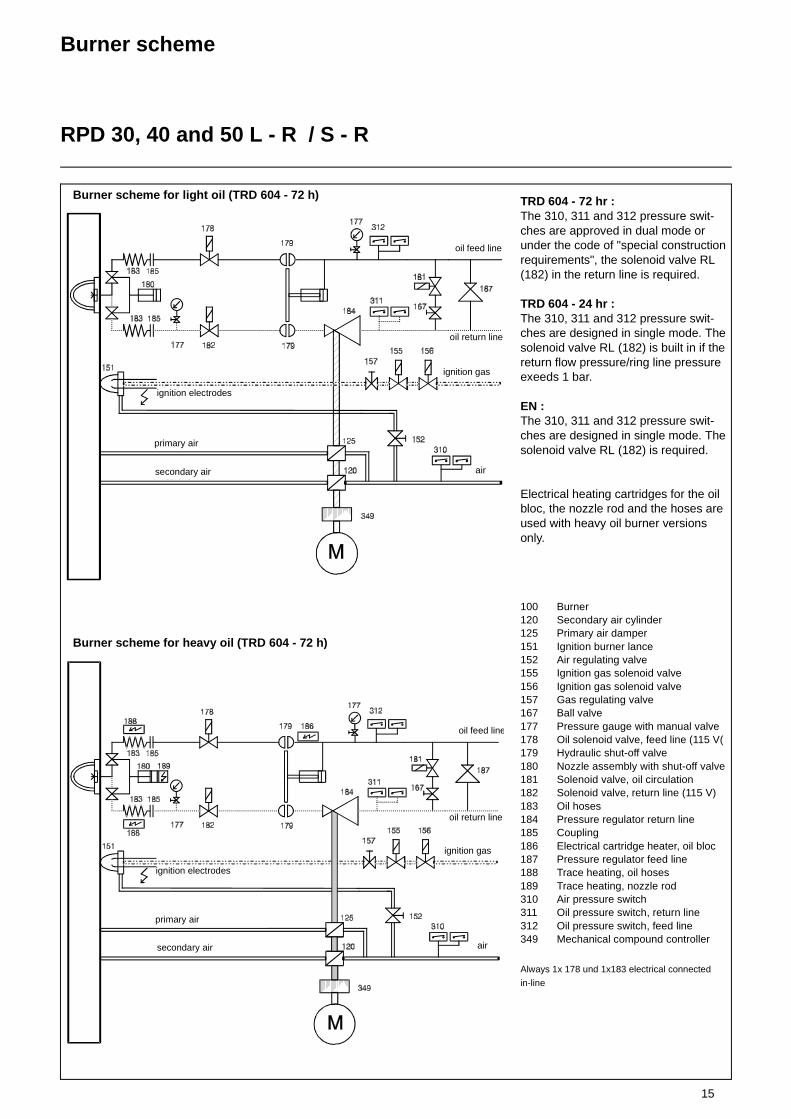
TRD 604 - 72 hr :The 310, 311 and 312 pressure swit-ches are approved in dual mode or under the code of "special construction requirements", the solenoid valve RL (182) in the return line is required.
TRD 604 - 24 hr :The 310, 311 and 312 pressure swit-ches are designed in single mode. The solenoid valve RL (182) is built in if the return flow pressure/ring line pressure exeeds 1 bar.
EN :The 310, 311 and 312 pressure swit-ches are designed in single mode. The solenoid valve RL (182) is required.
Electrical heating cartridges for the oil bloc, the nozzle rod and the hoses are used with heavy oil burner versions only.
Always 1x 178 und 1x183 electrical connected
in-line
100 Burner120 Secondary air cylinder125 Primary air damper151 Ignition burner lance152 Air regulating valve155 Ignition gas solenoid valve156 Ignition gas solenoid valve157 Gas regulating valve167 Ball valve177 Pressure gauge with manual valve178 Oil solenoid valve, feed line (115 V(179 Hydraulic shut-off valve180 Nozzle assembly with shut-off valve181 Solenoid valve, oil circulation182 Solenoid valve, return line (115 V)183 Oil hoses184 Pressure regulator return line185 Coupling186 Electrical cartridge heater, oil bloc187 Pressure regulator feed line188 Trace heating, oil hoses189 Trace heating, nozzle rod310 Air pressure switch311 Oil pressure switch, return line312 Oil pressure switch, feed line349 Mechanical compound controller
oil feed line
ignition electrodes
oil return line
air
primary air
secondary air
ignition gas
Burner scheme for light oil (TRD 604 - 72 h)
Burner scheme for heavy oil (TRD 604 - 72 h)
oil feed line
ignition electrodes
oil return line
air
primary air
secondary air
ignition gas

16
Burner scheme
RPD 60 - 100 L - R / S - R
TRD 604 - 72 hr :The 310, 311 and 312 pressure swit-ches are approved in dual mode or under the code of "special construction requirements", the second solenoid valve RL (182) in the return line is requi-red.
TRD 604 - 24 hr :The 310, 311 and 312 pressure swit-ches are designed in single mode. The second solenoid valve RL (182) is built in if the return flow pressure / ring line pressure exeeds 1 bar.
EN :The 310, 311 and 312 pressure swit-ches are designed in single mode. Both solenoid valves RL (182) are required.
Electrical heating cartridges for the oil bloc, the nozzle rod and the hoses are used with heavy oil burner versions only.
Always 1x 178 und 1x183 electrical connected
in-line
100 Burner120 Secondary air cylinder125 Primary air damper151 Ignition burner lance152 Air regulating valve155 Ignition gas solenoid valve156 Ignition gas solenoid valve157 Gas regulating valve167 Ball valve177 Pressure gauge with manual valve178 Oil solenoid valve, feed line (115 V)179 Hydraulic shut-off valve181 Solenoid valve, oil circulation182 Solenoid valve, return line (115 V)183 Oil hoses184 Pressure regulator return line185 Coupling186 Electrical cartridge heater, oil bloc187 Pressure regulator feed line188 Trace heating, oil hoses189 Trace heating, nozzle rod310 Air pressure switch311 Oil pressure switch, return line312 Oil pressure switch, feed line349 Mechanical compound controller
Burner scheme for light oil (TRD 604 - 72 h)
oil feed line
ignition electrodes
oil return line
air
primary air
secondary air
ignition gas
Burner scheme for heavy oil (TRD 604 - 72 h)
oil feed line
ignition electrodes
oil return line
air
primary air
secondary air
ignition gas

17
Hydraulic SchemeRPD 30 -50
Oil Control Block and Nozzle Rod DG 75
11
12 12
1414
16 1613
15
8
10
9 7 65
43 2
1
11
12 12
1414
16 16
1315
8
10
9 7 65
43 2
1
11
12 12
1414
1616
1315
8
10
9 7 65
43 2
1
Oil circuit at burner stand by(Zirkulation)
Oil circuit at burner pre-purge
Oil circuit at burner operation
1. Oil pressure pump2. Safety valve3. Oil filter 4. Pressure gauge (feed line)5. Oil regulating valve6. Manual valve (for bleeding)7. Circulating valve 9. Hydraulic cylinder for ball valves10. Oil regulating valve, return line
11. Pressure gauge (return line)12. Ball valve13. Inner nozzle oil line assembly14. Solenoid valves15. Return nozzle16. Pressure hoses

18
Hydraulic SchemeRPD 30 -100
Oil Control Block and Nozzle Rod MAT
11
12 12
14
14
14
14
1616
1517
17
17
17
13
10
9 7 65
43 2
1
11
12 12
10
9 7 65
43 2
1
14
14
14
14
1616
1513
Oil circuit at burner stand by(Zirkulation)
Oil circuit at burner operation
1. Oil pressure pump2. Safety valve3. Oil filter 4. Pressure gauge (feed line)5. Oil regulating valve6. Manual valve (for bleeding)7. Circulating valve 9. Hydraulic cylinder for ball valves10. Oil regulating valve, return line
11. Pressure gauge (return line)12. Ball valve13. Inner nozzle oil line assembly14. Solenoid valves15. Return nozzle16. Pressure hoses17. Non-return valves

19
1. oil solenoid valve circulation 2. oil regulating valve return flow 3. oil regulating valve bloc inlet pressure 4. regulating needle 5. spring 6. washer 7. shaft 8. surclip 9. O- ring seal N. 19 10. bush gland 11. gasket 12. washer
13. surclip 14. spring 15. washer 16. surclip 17. regulating needle 18. spring 19. washer 20. shaft 21. gasket 22. bush gland
29. shaft 30. piston 31. gasket 32. lock washer 33. nut M8 34. spring 35. spring cover 36. cover plate 37. aluminum washer 38. valve flange 39. double blocking valve 40. outer shaft ring 41. washer 42. fixing ring 43. valve cover 44. O ring gasket 45. cover 46. block body 47. nut M8
Oil C
on
trol B
lock

20
Mounting PositionLeak TestIgnition Gas ConnectionIgnition Burner Type ZT0
Mounting positionGas pressure regulators and valves can be mounted in vertical lines in any posi-tion within the 360° range. In horizontal lines they must not be mounted over-head and only 180° in the upper sector. The ball valve and filter can be mounted in any desired position. Take care that the housing does not make contact with the wall and is clear by minimum 20 mm. Do not use the spring bolt of the regulator and the solenoid elements of the valves as levers.
Leak testCheck the screwed joints and flanged connections for absence of leaks. The leak test of the joints should be made under pressure using only foaming agents approved by DVGW and not causing corrosion.
Electrical wiring of gas valvesCheck that the data given on the name-plate of the gas valves agree with the mains voltage.Open the terminal box of the valve. Feed the connection cable through the screwed union (conduit thread Pg 13.5) and connect the terminals marked accordingly.L = phaseN = zero conductor = protective conductor (green-yellow)
Disconnectable jointAn easy-to-disconnect joint with flat sealing (e.g. compensator) should be provided to allow the boiler door to be swivelled out if required for mainte-nance work on the boiler (furnace chamber). This compensator should also be designed to accommodate the axial or lateral expansion and absorb vibrations.
Ignition gas connectionAn ignition burner is used to ignite the main gas flame. The ignition gas line is branched out of the gas control group between the two gas valves and instal-led to the ignition burner on the shortest possible way. In the case of oil and dual-fuel burners the burner is ignited with propane supplied through a sepa-rate R „ propane connection. The igni-tion gas flow rate may be adjusted on the volumetric flow control valve of the ignition gas valve or directly on the igni-tion gas burner. The required gas pres-sure for the ignition gas burner is 50-150 mbar. It is advisable to install a gas pressure regulator upstream of the igni-tion gas burner. The air pressure for the ignition gas burner should be between 10 and 30 mbar. The boiler back pres-sure shall not be taken into account. The air pressure should be adjusted in accordance with the gas pressure to ensure an undelayed ignition and a good flame pattern.
1 Transformer unit with built-in ignition transformer
2 Electrical angular plug connector3 Gas connection, may be
connected on either side right and left with gas test socket
4 Air connection, mounted to transformer unit
5 Air test socket6 Igniter tube, mounted to air flange
7 Spacer ring8 Ignition electrode connection rods9 Gas tube10 Ignition electrode connection rods11 Gas nozzle for natural gas or
propane12 Mixing chamber
* The outside diameter will be 50 mm for tube lengths above 4000 mm and for all high-grade steel tubes.
Mounting flangeView A
Gas RP1/2normally left
Air Rp1Ignition Burner Type ZT0

21
Ignition Burner Type ZT0
Technical Data
Construction according to sectional drawingThe igniter consists mainly of the trans-former unit (Item 1) housing the ignition transformer, the igniter tube with air and mounting flange (Item 6), a gas tube (9) with nozzle (11) and the electrode car-rier ring (10). The igniter tube with the Rp1 air connection is bolted to the transformer unit. After the 4 bolts (Item 4) have been unscrewed it may be removed or turned by 90° if required by the position of the air connection. When turning the tubes care must be taken not to change the position of the inner supporting rings and rods because this might lead to operational trouble. The gas supply may be connected eit-her to the left-hand or right-hand ope-ning. The opening not used is closed with a screw plug which also carries the screw-in gas test socket (3). The elec-trode support ring (Item 10) is mounted to the end of the gas tube.
The ionization electrode and ignition electrode are extended with connecting rods (Item 8). These rods are installed through the bottom of the transformer housing in 2 ceramic insulators and car-ried by intermediate supporting rings (Item 7) spaced at 300 mm.
Flame monitorAn ionization electrode is provided for flame monitoring. The flame signal is generated by d.c. current which due to the ionization effect and the rectifier effect of the flame is caused to flow from the igniter tube earth via the flame to the ionization electrode and via the con-necting rod to the amplifier in the auto-matic furnace controller. The ionization electrode and ignition electrodes are adjusted in accordance with the dra-wing.
When installing new electrodes these must be bent, cut to length and adjusted as required. The internal resistance of the ionization system amounts to some megohms. Such a high resistance ensures a good insulating capacity of the electrodes and connecting rods. In a dust-laden com-bustion air environment it is therefore important to clean the insulators at shor-ter intervals. Humidity should be kept out. See also electrical function. The ceramic insulator of the ionization electrode must not be allowed to heat up above 500 °C because this could lead to shutdown on trouble. Therefore, a minimum air flow rate (10-20 % of the full-load rate) should be allowed to flow if this temperature is likely to be rea-ched by radiation or convection with the furnace chamber in hot condition and the burner flame turned off.
Technical data of ignition gas burner type ZT0
Fuel gases according to G 260Flame power max. 120 kWFlame length max. 600 mmGas connection Rp 1/2 right or leftAir connection Rp 1, may be turned by 4x90°Air flow rate max. 50 m³/hAir index 0.3-0.5; remaining air rate must be available from furnace chamberMax. ambient temperature 500°C in tube; if temperature is higher, keep combustion air
connected partly as cooling air; 0°C to +60°C in transformer unit
Transformer unit
Connection voltage 230 V, 50 HzConnector type plug connectorPower input ignition transformer 100 VA, 20% duty cycle (with thermal winding shield)
ignition 5 kV (2-3 seconds via automatic furnace controller)Ambient temperature 0°C to +60°CDegree of protection IP 54
Electrical connection
Cl. 1 (Mp)Cl. 8 (Ph) ignition transfer, primary Use shielded cable Z 912 F 00 for flame feedback.Cl. 10 ionization signal NOTE: The shield must not make contact with earth.

22
Ignition Burner Type ZT0
Gas Pressure AdjustmentParts List
Gas pressure adjustmentIn standard version the igniters are sui-table for a working range 50-150 mbar. If a higher gas pressure is required in the customer’s order, the two threaded gas inlet connections will be fitted with restrictors by the manufacturer already. The igniter will in this way be adjusted to the pressure above 150 mbar.If the higher inlet pressure is recognized at a later stage only, a restriction to maximum 150 mbar can also be achie-ved by means of a ball valve, for example.
Characteristicline Gas type Nozzle holes Flame length
P Propane 1x2,5 + 6x1,0 approx. 600 mm
M Natural gas 1x4,0 + 6x1,3 approx. 500 mm
N City gas 1x5,0 + 8x2,3 approx. 500 mm
Parts list
Item. Qty. Description Part No. Material
1 1 Transformer unit Z 112 K 5 Housing of GAL
2 1 Right-angle plug with 2 unions A 5 Z 1 10-pole, max. 2.5
3 1 Gas test socket Z 138 Z 2 Ms 58
4 4 Hexagon socket head screw W 826 F 10
5 1 Air test socket Z 138 Z 1 Ms 58
6 1 Igniter tube with rolled-in mixing chamber and mounting flange with Rp1 air inlet thread
Z 1050 Z...** GAL / steel
7 * Intermediate supporting ring with 2 ceramic insulators Z 545 F11
Z 960 K 4 St VII 23
8 2 Connecting rods Z 781 F...** Zinc-plated steel
9 1 Gas tube Z 521 F...** St 35
10 1 Electrode carrier ring Z 960 K 13 St VII 23
11 1 Gas nozzle Natural gasPropaneCity gas
Z 330 F 4013Z 330 F 2510Z 985 F 1
High-grade steel 1. 4104High-grade steel 1. 4104High-grade steel 1. 4104
12 - Mixing chamber with mixing ring Included in Item 6
High-grade steel, heat-resistant
* Quantity depends on pipe length: 3 intermediate rings per metre of tube length.** Additional data according to type (tube length).

23
Ignition Burner SettingsElectrode Carrier Ring
Frontview
Side view
110 mm for natural gas
90 mm for propane
Top view
Natural gas
Propane
Electrodes Z 707 F 3
Ceramic Z 545 F 11
Ring W 715F 101
Bush Z 789F 10
Preset amount of bend and adjustmentCut ionization electrode to length according to gas type.
24
Ignition Gas Solenoid Valve
Type MVD 505 / 5 single-stage
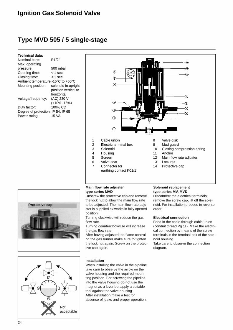
Technical data:Nominal bore: R1/2“Max. operating pressure: 500 mbarOpening time: < 1 secClosing time: < 1 secAmbient temperature:-15°C to +60°CMounting position: solenoid in upright
position vertical to horizontal
Voltage/frequency: (AC) 230 V(+10% -15%)
Duty factor: 100% CDDegree of protection: IP 54, IP 65Power rating: 15 VA
Main flow rate adjustertype series MVDUnscrew the protective cap and remove the lock nut to allow the main flow rate to be adjusted. The main flow rate adju-ster is supplied ex works in fully opened position. Turning clockwise will reduce the gas flow rate.Turning counterclockwise will increase the gas flow rate.After having adjusted the flame control on the gas burner make sure to tighten the lock nut again. Screw on the protec-tive cap again.
InstallationWhen installing the valve in the pipeline take care to observe the arrow on the valve housing and the required moun-ting position. For screwing the pipeline into the valve housing do not use the magnet as a lever but apply a suitable tool against the valve housing.After installation make a test for absence of leaks and proper operation.
Solenoid replacementtype series MV, MVDDisconnect the electrical terminals; remove the screw cap; lift off the sole-noid. For installation proceed in reverse order.
Electrical connectionFeed in the cable through cable union (conduit thread Pg 11). Make the electri-cal connection by means of the screw terminals in the terminal box of the sole-noid housing.Take care to observe the connection diagram.
1 Cable union2 Electric terminal box3 Solenoid4 Housing5 Screen6 Valve seat7 Connector for
earthing contact K01/1
8 Valve disk9 Mud guard10 Closing compression spring11 Anchor12 Main flow rate adjuster13 Lock nut14 Protective cap
Protective cap
Notacceptable
25
Oil ConnectionFuel Oil Supply
Oil connectionFor the installation of a furnace system care should be taken to observe the applicable rules and regulations. When installing an oil burner be sure to follow the recommendations outlined for oil-fired furnace systems (DIN 4787, DIN 51603 Parts 1&2, TRD 411). DIN 4736 Parts 1&2 describes the safety requirements applicable to the oil sup-ply systems of oil burners. DIN 4755 Part „Oil furnaces in heating installati-ons (safety requirements)“ outlines the safety recommendations for oil furnace systems of steam boilers.The installer has the duty to inform himself of the regulations applicable to gas and oil furnace systems.
Fuel oil supplyComplete oil feeding groups are availa-ble for the supply of the furnace systems with fuel oil. A fuel oil supply unit may consist of ball stop valve, suc-tion filter, pressure gauge, pump with coupling and three-phase motor. All units are all finished ready for connec-tion and mounted with anti-vibration ele-ments on an oil collecting tray. The oil supply lines must be selected in accordance with the technical instruc-tion sheets and installed in line with the applicable specifications. The total pipe-line length is understood to be the length of all horizontal and vertical lines and bends. The maximum permissible vacuum at the suction port of the pump may be -0.6 bar. A higher vacuum will lead to the escape of gas resulting in an unsteady delivery and damage to the pump. All connections must be tightened to avoid leaks. The sealing rings used should be of copper, aluminium or pla-stic. In no case should hemp or similar sealing material be used. The pipelines must be cleaned before they are con-nected to the pump.
Ring line operationIf several burners and storage tanks are installed in a system or if there is a large distance between the burner and the storage tank, a ring line system with gas-air separator will be needed for supplying the burners. NOTE: In case of pressurized oil feed, the suction pressure of the pump should not exceed 5 bar. All lines must be fixedly installed, welded to oil-tight stan-dards or connected with oil-tight unions or flanges.Flexible tubes are allowed only as con-necting pieces between the fixed line and the burner. The flexible tubes should be installed properly (in hanging position) and free of sharp bends. For the installation of the flexible tubes take care these do not get twisted. They should not be subject to torsional stress neither at the stage of installation nor during subsequent movements.
Oil pressure pump fillingPrior to initial operation make sure to fill the oil pressure pump and oil feed line with oil to prevent the pump from dry running and getting seized.
Oil filterIt is recommended to install a filter directly upstream of the pump to sepa-rate dirt particles contained in the oil or any other foreign matter produced during installation. When a fuel oil unit is mounted this will be fitted with an oil fil-ter already.
Starting the oil pump- Make sure all stop valves are
open.- Check the pump for direction of
rotation.- The safety overflow valve in the
pump is preset at 40 bar and may be readjusted by duly authorized specialists only.
Pressure atomizerThe oil throughput rate of the nozzle and thus the burner output is controlled by an oil regulator valve installed in the return line and coupled to the actuator and compound controller.
The oil throughput rates and oil flow pressures downstream of the nozzle rod must be set according to the applicable nozzle characteristic. As the oil control valve is closed or ope-ned the oil throughput rate of the nozzle will be increased or reduced, respec-tively.The oil pressure upstream of the nozzle rod must be set at 28 bar to 30 bar. Depending on the version this can be can be adjusted either on the fuel oil station or on the oil control block of the burner.

26
Oil ConnectionFuel Oil Supply
Oil connectionFor the installation of a furnace system care should be taken to observe the applicable rules and regulations. When installing an oil burner be sure to follow the recommendations outlined for oil-fired furnace systems (DIN 4787, DIN 51603 Parts 1&2, TRD 411). DIN 4736 Parts 1&2 describes the safety requirements applicable to the oil sup-ply systems of oil burners. DIN 4755 Part „Oil furnaces in heating installati-ons (safety requirements)“ outlines the safety recommendations for oil furnace systems of steam boilers.The installer has the duty to inform himself of the regulations applicable to gas and oil furnace systems.
Fuel oil supplyThe operational reliability of a burner system depends greatly on the oil sup-ply conditions.Oil supply lines must be determined according to the technical instruction sheets and installed by strict adherence to the applicable regulations. All joints must be mounted with due care to ensure they are absolutely tight. The sealing rings used must be made from copper, aluminium or plastic. In no case should hemp or a similar material be used. Make sure to remove any dirt from the pipelines before mounting them to the pump.
Normally, a ring pipe system will be used.In addition to the electric tracing lines, a ring pipe system for heavy oil installati-ons comprises the following major com-ponents:
oil delivery pump,oil filter,gas-air vent, andpressure control valves.
The electric tracing lines and the tank heaters will ensure that the fuel oil to be delivered is kept in a pumpable state. An oil filter must be installed in the feed line upstream of each burner to avoid that dirt particles and other impurities possibly left behind after pipe installa-tion cannot damage the solenoid and pressure control valves. Steam tracing or hot-water tracing systems can be used instead of the electric tracing lines.
To avoid burner trouble due to entrained air, a gas-air vent must be provided at the uppermost position of the ring pipe system.
The ring pipe pressure must be control-led in dependence of the fuel oil tempe-rature.As can be seen from the chart below, the static pressure of the oil at 130°C must be minimum 3 bar, for example.
Oil pressure in dependence of operating temperature
The fuel oil withdrawn from the ring pipe or gas-air vent is pumped to an oil pre-heater and on to the burner by means of a high-pressure pump. The return oil from the burner is fed into the ring pipe in any case and not directly into the tank.
Oil pressure pump fillingPrior to initial operation make sure to fill the oil pressure pump and oil feed line with oil to prevent the pump from dry running and getting seized.
Oil filterIt is recommended to install a filter directly upstream of the pump to sepa-rate dirt particles contained in the oil or any other foreign matter produced during installation. When a fuel oil unit is mounted this will be fitted with an oil fil-ter already.
Starting the oil pump- Make sure all stop valves are
open.- Check the pump for direction of
rotation.- The safety overflow valve in the
pump is preset at 40 bar and may be readjusted by duly authorized specialists only.
Pressure atomizerThe oil throughput rate of the nozzle and thus the burner output is controlled by an oil regulator valve installed in the return line and coupled to the actuator.
The oil throughput rates and oil flow pressures downstream of the nozzle rod must be set according to the applicable nozzle characteristic. As the oil control valve is closed or ope-ned the oil throughput rate of the nozzle will be increased or reduced, respec-tively.The oil pressure upstream of the nozzle rod must be set at 28 bar to 30 bar. Depending on the version this can be can be adjusted either on the fuel oil station or on the oil control block of the burner.
0
1
2
3
4
5
100 110 120 130 140 150 160Temperatur °C
Dru
ck b
ar
Temperature °C
Pre
ssur
e ba
r

27
Medium pressure screw pumps
InstallationCommissioningMaintenance
Medium pressure screw pumps
GeneralScrew pumps are rotating positive dis-placement pumps with strong suction, which can be used with self-lubricating agents.
1. Application guidelines
1.1 Shaft seals for normal versions
1.2 Pressure relief valveThis valve protects the pump against overloading and should not be used as a pressure control valve. This is absolu-tely necessary if a shut-off device is fit-ted in the pressure pipe. Standard pressure setting unless otherwise requi-red at the time of ordering. Low pres-sure pumps (type N) approx. 6 bar, medium pressure pumps (type M) approx. 40 bar or 10% above the speci-fied operating pressure, as with C-types. By turning the adjustment screw in a clockwise direction = pressure increase.
2. Installation
2.1Clean any plant parts (ensure no dirt or loose particles in the pipes) and fit pipes (flange) without any stress. Observe direction of flow as well as any possible heat expansion of the pipes.
2.2Ensure stress-free fitting of the pump or base frame.
2.3 CouplingMotor and pump shafts must be aligned. Axial play between the Coupling halves approx. 1.5 mm. It should be possible to turn the whole unit of pump shaft-Cou-pling-Motor shaft by hand. Installation of the coupling halves: Sliding on (tapping not permitted) in heated condition (min. 100°C); Press plastic couplings home in cold condition.
2.4Check direction of rotation of the motor and the pumps and protect the motor by means of a motor protection switch.
3. Commissioning
3.1 The pump must not be allowed to run dry!Before initial commissioning of the pump fill the pump with operating medium and open suction and shut-off devices on the pressure side. The medium must be free from solids.
3.2With hot medium (above 100°C) heat the pump before starting (pump heating facility). ATTENTION! The medium in the pump and pipes must be able to expand freely during heating (develop-ment of unauthorized pressures with enclosed medium).
3.3Viscous medium, which can only be pumped after heating, must be heated first in the pump and pipes (pump hea-ting as well as secondary heating for pipes). ATTENTION! Heat expansion of the medium (see above).When pumping heavy heating oil it is essential that cold starting of the pump is avoided (use pump heating provided), as this could also damage the shaft seal.
3.4Vent the pressure pipe during initial starting of the pump.
3.5Switching off the pump: Residual static pressure in the pressure pipe must no exceed that of the permissible supply pressure. If necessary, de-pressurize the pump through the non-return valve, as this pressure pressurizes the shaft seal which in turn could damage the seal. The same applies to parallel ope-ration of several pumps.
4. MaintenanceSpecial maintenance of the screw pumps is not required. In case of damage to the pump of the installation it is possible that medium will leak out. In order to avoid subsequent damage it is recommended that respective warning devices are fitted.
Type of seal Max. supplypressure
Max.Temperature
Rotary shaft 0,5 bar 80°CPacking rings 3 bar 150°CAxial face seal 5 bar 150°C

28
Medium pressure screw pumps
Technical specificationsFunctionVersions
Technical specifications
FunctionScrew pumps have three rotating spind-les, of which the main spindle supplies the hydraulic power and the auxiliary spindles, which run free, have only a rotating function. The two-speed main and auxiliary spindles create supply chambers within the enclosed housing, which move constantly from the suction to the pressure side. Due to this prin-ciple the screw pumps can also operate under high pressures, revolutions and provide strong suction, they are extre-mely quiet and almost pulse-free.
Safety valveAll types of medium pressure pumps can be supplied on request with or wit-hout a spring-loaded pressure control valve. The valve is installed to protect the pump and/or installation against excess pressure, but cannot be used solely as a control valve.
MaterialsSupply spindles Nitrided steelHousing Grey cast iron(M55 to M210) Nodular graphite
ironOperating housing Al-Si alloy *Cover plate Al-Si alloy *
* Guarantees the best emergency running characteristics and long service life
Flow rate Approx. 3 - 420 l/min
Operating pressure Max. 40 bar
Supply pressure See under versions
Operating temp. See under versions
Viscosity 1.0 E (6 cSt) to 100 E (758 cSt)and greater
Direction of rotation Right, viewed from drive
Heating Supplied on request
1. Main spindle2. Auxiliary spindle3. Enclosed housing4. Pump housing5. Safety valve (adjustable)6. Main spindle bearing7. Seal8. Compensating bore9. Compensating pistonS Suction chamberD Pressure chamber
The axial forces acting on the feed screws are balanced (compensated) by the compensating piston (9) and compensating bores (8).
VersionsMedium pressure screw pumps, as shown on the following pages, are supplied in various constructions. Depending on the application, the following types of seal are available:
Rotary shaft sealing rings
Normal packing and rotary shaft seal
Temperature: Max. 150°C (above 150°C on request)Supply pressure: Max. 5 bar (above 5 bar on request)
Temperature: Max. 80°CSupply pressure: Max. 0.5 bar
Temperature: Max. 80°CSupply pressure: Max. 0.5 bar
Axial face seal

29
Burner Pump AssemblyElectrical Connection
Burner pump assembly
The installation material and all electri-cal connections and earthing points must be in accordance with the VDE 0116 specifications and the local regulations. The electrical connection of the burner must be made as shown in the circuit diagram attached hereto. The electrical control lines are installed through the screwed cable joints and connected to the numbered terminal strip in accordance with the circuit dia-gram. Control boxes related to the bur-ner must also be connected in accordance with the enclosed circuit diagram and VDE 0116 and taking into account the local regulations. After the electrical connections have been com-pleted a check must be made for the correct wiring of all items of the equip-ment. Also the direction of rotation of the air fan and of the pump should be checked.
1 Electrical terminal box2 Plug connector3 Terminal strip4 Cable bushings
Electrical connection
1 Stop valve2 Pressure/vacuum gauge3 Ball valve4 Oil pressure pump
(volumetric)5 Drip tray6 Oil filter7 Ball valve8 Flange connection9 Pump bracket10 Pump-end coupling11 Motor-end coupling12 Electric motor

30
Return Nozzle Rod DG 75
Functional description
Pre-flushingThe oil delivered by the burner pump will enter the feed pipe (Item 2) via the connection block (Item 1). Then it flows through the feed pipe to the closing taper plug of the regulating piston (Item 4). The plug is permanently pressed against the nozzle head (Item 7) by a cylindrical pressure spring (Item 5) so that the feed pipe is kept in closed posi-tion. At the same time, pressure is app-lied to the connecting rod (Item 8) by a spring (Item 6) so that the valve needle (Item 12) is pressed against the return opening of the nozzle head (Item 7), thus keeping the latter in closed posi-tion. In this position the oil may only enter the return pipe (Item 9) through the opened flushing hole (Item 13) and will return to the gas-air separator and finally to the fuel tank. This will give an effective flush up to the nozzle.
Operating functionAfter the air pre-flushing period, an electromagnet will be operated and apply a tensile force via an arm (Item
10) to the connecting rod (Item 8). As the valve needle and the regulating piston are connected to one another, the feed pipe and return pipe will be opened at the same time so that the oil can flow to the nozzle through the hole of the nozzle head.At the same time the regulating piston (Item 4) will shut off the flushing hole (Item 13) to the return pipe. This causes the oil to be forced to the nozzle with part of the oil flowing back through the return opening of the nozzle (Item 11) and the nozzle rod. The return oil flow rate is controlled in dependence of the pressure by means of an output pres-sure regulating valve in accordance with the required load. When the burner is stopped the sole-noid actuator will be turned off so that through the action of the pressure springs in the feed and return pipes the valve needle and the regulating piston will shut off the return pipe and feed pipe, respectively.For the adjustment of the transmission arm (Item 10) it should be ensured that the solenoid actuator (Item 14) is de-energized. Care should also be taken to avoid any mechanical loads. Pull out
the anchor (Item 15) to the stop, uns-crew the lock nut (Item 16) and turn the anchor (Item 15). When the solenoid actuator is de-energized there should be a noticeable backlash in the trans-mission linkage. When operated electri-cally, the solenoid actuator should produce and audible noise when making contact with the mechanical stop. The valve needle (Item 12) must be operated over its full travel of 4 mm. Tighten the lock nut (Item 16).
Lift
Lift
Flushing nozzle rod DG-75 (complete)
Description of items1. Connection block2. Feed pipe3. Rod block4. Regulating piston5. Feed pressure spring6. Return pressure spring7. Nozzle head8. Connecting rod9. Return pipe10. Arm11. Return feed12. Valve needle13. Flushing hole
Transmission arm
Mount for arm
Feed Return

31
Return Nozzle Rod MAT
Functional descriptionThe oil delivered by the burner pump will enter the feed pipe (9) via the connection block (10). Then it flows through the feed pipe (9) at the pre-set pressure directly to the return nozzle. Part of the oil delivered will be returned through the return flow pipe (6) via the return flow hole of the nozzle.
The return flow rate is controlled according to the required output using an output pressure control valve.Approved shut-off valves are installed directly upstream of the inlet to the nozzle rod in the oil feed and oil return lines.
1. Union nut2. Nozzle plate3. Intermediate plate4. Swirl chamber 5. Nozzle rod6. Return pipe7. Feed flow8. Return flow9. Feed pipe10. Connection block

32
Throughput Rate CharakteristicsLight Fuel Oil
Return Nozzle MK 27
Article-No.: 145.513.5899
Oil
[kg
/h]
m·
2 al
ph
a [°
]
p return [bar]
Test conditions:

33
Throughput Rate CharakteristicsLight Fuel Oil
Return Nozzle MK 27
Article-No.: 145.513.5902
Oil
[kg
/h]
m·
2 al
ph
a [°
]
p return [bar]Test conditions:

34
Throughput Rate CharakteristicsLight Fuel Oil
Return Nozzle MK 27
Article-No.: 145.513.5913
Oil
[kg
/h]
m·
2 al
ph
a [°
]
p return [bar]
Test conditions:

35
Throughput Rate CharakteristicsLight Fuel Oil
Return Nozzle MK 27
Article-No.: 145.513.5924
Oil
[kg
/h]
m·
2 al
ph
a [°
]
p return [bar]
Test conditions:

36
Throughput Rate CharakteristicsLight Fuel Oil
Return Nozzle MK 50
Article-No.: 145.513.5946
Oil
[kg
/h]
m·
2 al
ph
a [°
]
p return [bar]
Test conditions:

37
Throughput Rate CharakteristicsLight Fuel Oil
Return Nozzle MK 50
Article-No.: 145.513.5957145.513.5968
Oil
[kg
/h]
m·
2 al
ph
a [°
]
p return [bar]
Test conditions:
38
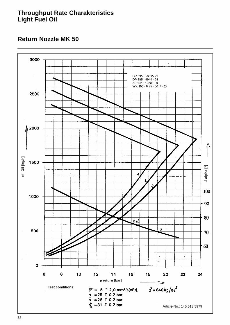
Throughput Rate CharakteristicsLight Fuel Oil
Return Nozzle MK 50
Article-No.: 145.513.5979
Oil
[kg
/h]
m·
2 al
ph
a [°
]
p return [bar]
Test conditions:
39
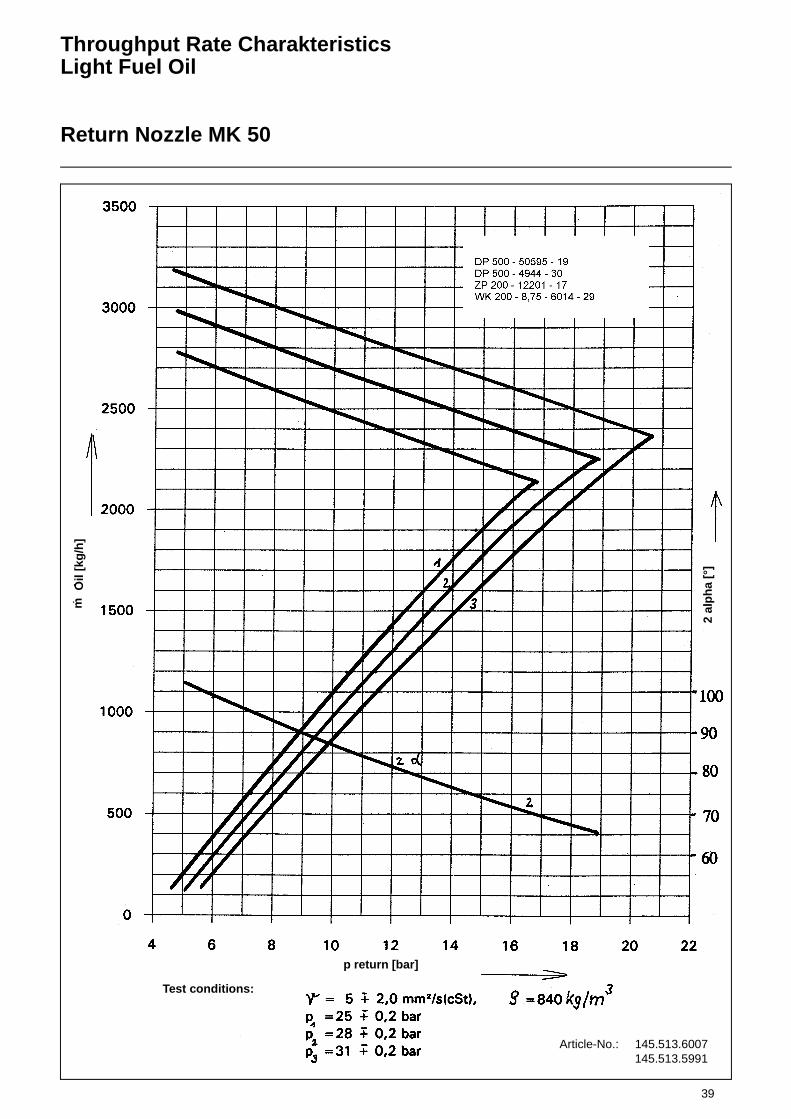
Throughput Rate CharakteristicsLight Fuel Oil
Return Nozzle MK 50
Article-No.: 145.513.6007145.513.5991
Oil
[kg
/h]
m·
2 al
ph
a [°
]
p return [bar]
Test conditions:

40
Throughput Rate CharakteristicsHeavy Fuel Oil
Return Nozzle MK 27
Article-No.: 145.513.5899
Oil
[kg
/h]
m·
2 al
ph
a [°
]
p return [bar]
Test conditions:
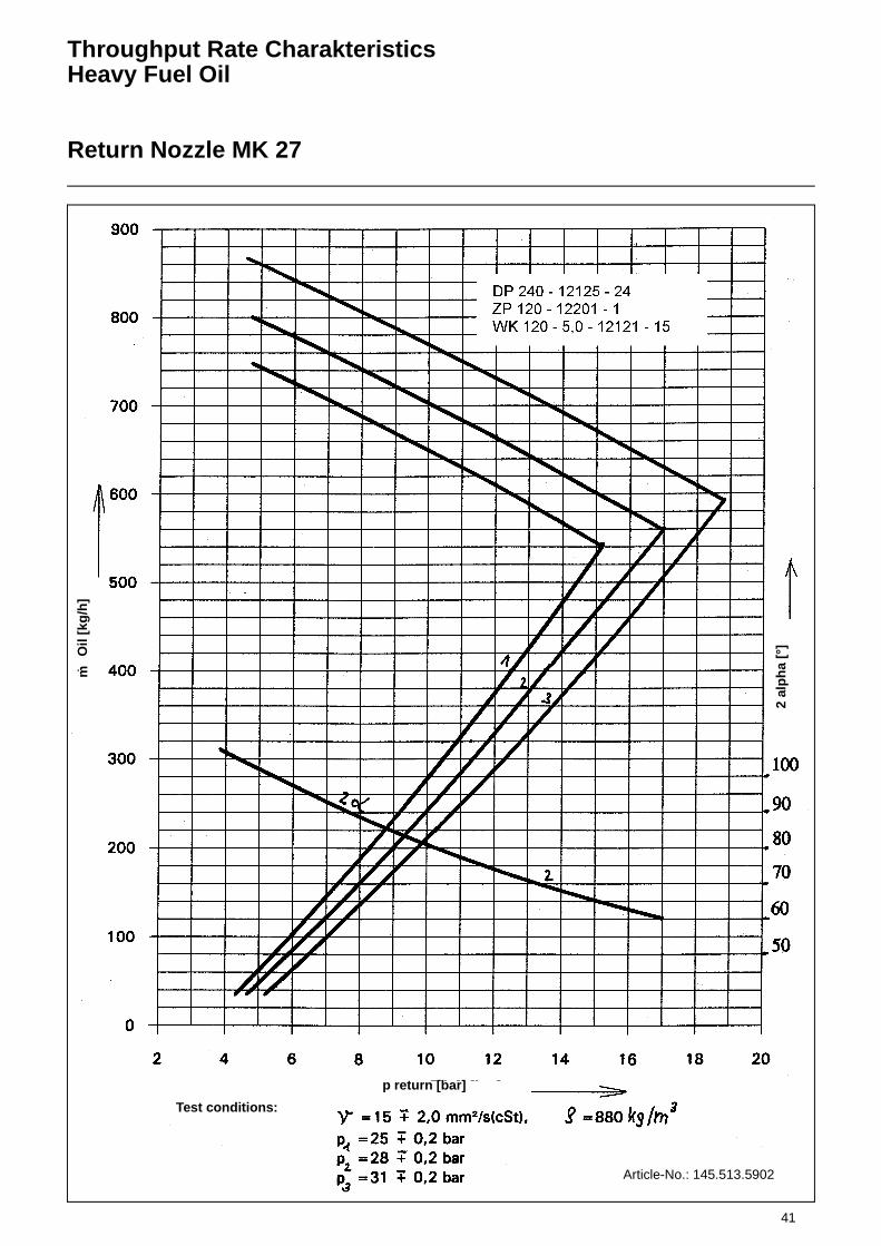
41
Throughput Rate CharakteristicsHeavy Fuel Oil
Return Nozzle MK 27
Article-No.: 145.513.5902
Oil
[kg
/h]
m·
2 al
ph
a [°
]
p return [bar]
Test conditions:

42
Throughput Rate CharakteristicsHeavy Fuel Oil
Return Nozzle MK 27
Article-No.: 145.513.5913
Oil
[kg
/h]
m·
2 al
ph
a [°
]
p return [bar]
Test conditions:

43
Throughput Rate CharakteristicsHeavy Fuel Oil
Return Nozzle MK 27
Article-No.: 145.513.5924
Oil
[kg
/h]
m·
2 al
ph
a [°
]
p return [bar]
Test conditions:

44
Throughput Rate CharakteristicsHeavy Fuel Oil
Return Nozzle MK 50
Article-No.: 145.513.5946
Oil
[kg
/h]
m·
2 al
ph
a [°
]
p return [bar]
Test conditions:

45
Throughput Rate CharakteristicsHeavy Fuel Oil
Return Nozzle MK 50
Article-No.: 145.513.5957,145.513.5968
Oil
[kg
/h]
m·
2 al
ph
a [°
]
p return [bar]
Test conditions:

46
Throughput Rate CharakteristicsHeavy Fuel Oil
Return Nozzle MK 50
Article-No.: 145.513.5980
Oil
[kg
/h]
m·
2 al
ph
a [°
]
p return [bar]
Test conditions:

47
Throughput Rate CharakteristicsHeavy Fuel Oil
Return Nozzle MK 50
Article-No.: 145.513.5979
Oil
[kg
/h]
m·
2 al
ph
a [°
]
p return [bar]
Test conditions:

48
Throughput Rate CharakteristicsHeavy Fuel Oil
Return Nozzle MK 50
Article-No.: 145.513.5991145.513.6007
Oil
[kg
/h]
m·
2 al
ph
a [°
]
p return [bar]
Test conditions:

49
Dimensions of the Mixing Unit(standard versions)
RPD 30 - RPD 80
RPD 30 RPD 40
RPD 50 RPD 60
RPD 70 RPD 80

50
Draw-out and Swing Mechanism
Burner Settings
Draw-out and swing mechanismThe duobloc burners type RPD are equipped with a draw-out and swing mechanism. This makes it possible to pull out and swing away the complete central tube for maintenance access to the mixing head and for adjusting the mixing and ignition units. Prior to this, the fastening bolts of the central tube must be unscrewed. The baseplate of the central tube carries the ignition burner, flame detector, nozzle rod assembly (only for oil and dual-fuel burners) and primary air connection. After the central tube has been remo-
ved, the air damper in the burner hou-sing will also be accessible.
NOTE: Before removing and swinging away the central tube take care to mount the draw-out and swing mecha-nism, disconnect the electric plug con-nectors of the flame detector and ignition burner, remove the primary air connection and disconnect the oil hoses (in oil and dual-fuel burners) with the quick-action couplings provided for this purpose.
Burner head adjustments
Burner combustion head adjustmentsIn order to enable service work on the burner combustion head and for adjust-ments of the ignition system the com-plete burner insert can be removed (see burner hinge arrangement). In case of component replacements or service work on the components of the burner head the correct position of the burner head components have to checked and if necessary the appropriate adjust-ments have to be carried out.The correct measurements can be seen in the burner dimensional sheet.The ignition electrodes must be set according to the dimensions shown in the diagramm.As the spray pattern of the oil nozzle depend on nozzle size the given dimen-sions can only be approximations. It may be necessary for the commission-ing engineer to alter the base settings to achieve the best start performance. The distance between nozzle tip and turbu-lator face depends on the nozzle spray pattern and the size of the turbulator core hole. The distance has to be adju-sted by the commissioning engineer so that the oil cone will impinge on the tur-bulator.The works setting of the burner head is carried out as shown in the dimensional sheet. In the base setting the nozzle face is positioned flush with the turbula-tor inner hole i.e. setting "0".It is recommended to note the distance between nozzle rod positioning bush and the end of the protruding nozzle rod as reference position.
123
4
5
6
7
Burner combustion head1 Burner tube2 Flame tube3 Cylinder for air stabilization4 Ignition Burner5 Turbulator6 Nozzle7 Primary air duct

51
Air Flow AdjustmentOil Flow Adjustment
Air adjustmentCheck that the air swirler setting is in accordance with the furnace/ combu-stion chamber geometry and re-set if required. In order to ensure uniform dis-tribution, close the air swirler at the air pipe entry against air inlet. The air curve of the compound controller is factory-set so that the air cylinder is closed at mini-mum settings and open at maximum settings.The combustion air ratio (secondary air) to the fuel can be obtained over the whole of the output range by turning the screws, which is then checked by measuring the exhaust.Before the compound controller screws can be adjusted, the lock nuts on the front face and underside of the com-pound controller must be loosened. Set-ting of the primary air is also carried out via a cam disk and it can be set accura-tely by adjusting the threaded studs as required. With a large control range the minimum combustion output is set by means of the primary air.
During adjustment care must be exerci-sed to ensure that over the whole of the control range the air pressure at the central pipe (primary side) is 1.5 - 2 mbar higher than the combustion cham-ber pressure.
Oil adjustmentFor taking into operation, the oil control block with flow control valve in the return line will be preset. The pump pressure is set at approx. 28 bar and the pressure upstream of the control valve at approx. 5 to 18 bar. After loose-ning of the lock screws of the socket-headed studs and sliding ball, the con-trol curve is adjusted over the whole control range by means of the cam disk, after which setting is then locked with the lock screws.
Heavy fuel oilHeavy fuel oils must generally be hea-ted up. On the one hand, this is perfor-med in the fuel oil storage tank to keep the oil in a pumpable state because the temperature must be above the setting point. Further preheating is required in the service tank, fluid preheater or elec-tric preheater to ensure the heavy fuel oil can be properly atomized and burns
readily. The level of preheating depends on the viscosity of the fuel oil and can be determined from the viscosity-tem-perature diagram. The atomizing visco-sity is at 12 to 15 cSt.
Spindle-flame
Longflame
Average lengthflame
Shortflame
Air swirler position
Flame formation
POS 1Air swirler angle Pressure loss
0 - 20°30 mbar
POS 2Air swirler angle Pressure loss
20 - 40°38 mbar
POS 3Air swirler angle Pressure loss
40 - 55°45 mbar
POS 4Air swirler angle Pressure loss
55 - 70°55 mbar
52
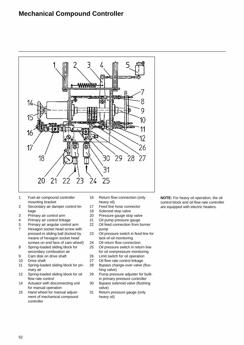
Mechanical Compound Controller
1 Fuel-air compound controller mounting bracket
2 Secondary air damper control lin-kage
3 Primary air control arm4 Primary air control linkage5 Primary air angular control arm7 Hexagon socket head screw with
pressed-in sliding ball (locked by means of hexagon socket head screws on end face of cam wheel)
8 Spring-loaded sliding block for secondary combustion air
9 Cam disk on drive shaft10 Drive shaft11 Spring-loaded sliding block for pri-
mary air12 Spring-loaded sliding block for oil
flow rate control14 Actuator with disconnecting unit
for manual operation15 Hand wheel for manual adjust-
ment of mechanical compound controller
16 Return flow connection (only heavy oil)
17 Feed line hose connector18 Solenoid stop valve20 Pressure gauge stop valve21 Oil pump pressure gauge22 Oil feed connection from burner
pump23 Oil pressure switch in feed line for
lack-of-oil monitoring24 Oil return flow connection25 Oil pressure switch in return line
for oil overpressure monitoring26 Limit switch for oil operation27 Oil flow rate control linkage28 Bypass change-over valve (flus-
hing valve)29 Pump pressure adjuster for built-
in primary pressure controller30 Bypass solenoid valve (flushing
valve)31 Return pressure gauge (only
heavy oil)
NOTE: For heavy oil operation, the oil control block and oil flow rate controller are equipped with electric heaters.

53
Pressure Setting
Oil pump pressure settingBefore commissioning the pump and oil pipes must be primed and vented.
1. Pump pressure- 28 to 30 bar for light fuel oil- 30 to 32 bar for heavy fuel oilSo as to protect the pump against excess pressures, the oil pressure con-trol valves of the high pressure pump have been factory set to 40 bar. The effective pump pressure is set and adju-sted at the burner control block or at the pressure control valve.
2. Pressure setting at the control valve (loop feeder pipe) at the burner pipe pressure
Light fuel oil settingLoop feeder pipe pressure 1,2 - 1,6 bar
Heavy fuel oil settingIn order to avoid evaporation of the water in the fuel oil, the pressure in the loop feeder pipe must be at least -see table:
Pressure control valveIn the piston-type pressure control valve, a piston (1) movably arranged in a cylinder is pressed against the valve needle (3) by a spring (2). As the pres-sure on the side of the valve needle rises above the spring pressure, the piston will be lifted and the oil caused to flow over to the pressureless side.For the installation of overflow valves of this type the following general informa-tion should be observed:The spring side (spring can be seen from outside) must in any case be cho-sen to be the return side, i.e. the pres-sureless side. Consequently, the direction of overflow is from the pressu-rized side to the pressureless spring side. Any counterpressure on the return side must thus be added to the selected spring pressure setting.It is of no consequence for the operation of this type of valves whether they are mounted in continuous lines or at line ends.The desired pressure is selected by means of the set screw (4). Turning the set screw (4) clockwise will increase the pressure, and turning it counterclock-wise will reduce the pressure.
Oil temperature at the burner
Loop feeder pipe pressure
125 °C 3,0 bar
130 °C 3,5 bar
135 °C 4,0 bar
140 °C 4,5 bar
4
2
1
3
Return
Feed
Light oil version Heavy oil version

54
Removal and Replacing the Shaft Seal of the Return Flow Nozzle Assembly DG 75
Removal:Before removal make a note of all rele-vent dimensions of the transmission lever etc.
1. Remove lock-nut (2), domed nut (1) and the connecting piece (3).
2. Remove end nut (4).3. Slide out the shaft seal (must not
be re-used).
Replacement:
1. In place of the end nut (4) use location tool (5).
2. Remove plug in sleeve (6) (fitted for protection of sleeve only) and move sleeve over threads and valve needle.
3. Using a piece of pipe, slide the new seal over sleeve (6) through the locating tool (5) until it bottoms in the seal housing (8). (The seal should not be compressed).
4. Remove the special tools.5. Replace the end nut (4), connec-
ting piece (3), lock nut (2) and domed nut (1).
6. Tighten the locking nut to the domed nut.
55
Oil Pressure SwitchAir Pressure Switch
Air pressure switchThe air pressure switch is provided for monitoring the pressure of the combu-stion air fan. The pressure switch DL 50A has been designed for switching on, off or over an electric circuit in the case of changes of the actual pressure levels from the set-point setting. The pressure switch DL 50A can be used as overpressure, vacuum or differential pressure monitor for air and non-aggressive gases but not for gases according to DVGW Worksheet G 260/l.
Determining the differential pre-flushing pressure and adjusting the differential pressure switch• Burner in the pre-aeration phase.• Measure pressure on test
connection (2).• Measure vacuum on test
connection (3).• Add the measured pressures.• Set the scale to 90% of the calculated
value.
CertificationThe pressure switch has been tested in accordance with DIN 3398 Part 2 and is registered by CE/DIN-DVGW. It has been registered in other important gas consumption countries.
Switch function testTest buttons are provided to check the switch functions for proper operation (with safety cut-out and interlock). The burner is normally run in partial-load condition when testing the safety functions. On pressing button (4) the vacuum will be removed which causes the differential pressure to drop below the required level. If it is necessary to test the pressure switch functions under full-load conditions this may be done by pressing button (1).
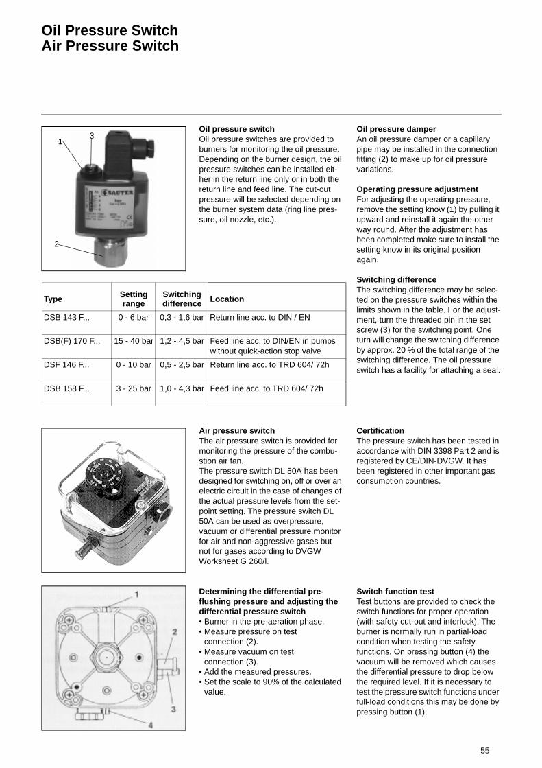
Oil pressure switch Oil pressure switches are provided to burners for monitoring the oil pressure. Depending on the burner design, the oil pressure switches can be installed eit-her in the return line only or in both the return line and feed line. The cut-out pressure will be selected depending on the burner system data (ring line pres-sure, oil nozzle, etc.).
Oil pressure damperAn oil pressure damper or a capillary pipe may be installed in the connection fitting (2) to make up for oil pressure variations.
Operating pressure adjustmentFor adjusting the operating pressure, remove the setting know (1) by pulling it upward and reinstall it again the other way round. After the adjustment has been completed make sure to install the setting know in its original position again.
Switching differenceThe switching difference may be selec-ted on the pressure switches within the limits shown in the table. For the adjust-ment, turn the threaded pin in the set screw (3) for the switching point. One turn will change the switching difference by approx. 20 % of the total range of the switching difference. The oil pressure switch has a facility for attaching a seal.
1
2
3
Type Setting range
Switching difference Location
DSB 143 F... 0 - 6 bar 0,3 - 1,6 bar Return line acc. to DIN / EN
DSB(F) 170 F... 15 - 40 bar 1,2 - 4,5 bar Feed line acc. to DIN/EN in pumps without quick-action stop valve
DSF 146 F... 0 - 10 bar 0,5 - 2,5 bar Return line acc. to TRD 604/ 72h
DSB 158 F... 3 - 25 bar 1,0 - 4,3 bar Feed line acc. to TRD 604/ 72h

56
Setting Pressure Switches and Control System
Setting of the oil pressure switchThe oil pressure switch is factory-set.The supply pressure switch is set in such a way, that perfect atomization is guaranteed. The return pressure switch is factory-set to 2 bar.The pre-set return pressure should nor-mally be 1 bar above the loop feeder system. After having set the correct pressure ensure that the setting screw is securely locked.
Setting of the air pressure switchThe differential pressure between bur-ner housing (overpressure) and air box (subatmospheric pressure) is measured with the burner in full-load condition. The pressure setting of the air pressure switch must therefore be smaller than the differential pressure measured. For adjustment, remove the protective hood and turn the setting scale accordingly.
Switching functions of air pressure switchWith increasing pressure:
P1 opensP2 closes
With decreasing pressure:P1 closesP2 opens
An industrial controller type KS 92 is used for the steplessly adjustable bur- ners. This controller has been specifi- cally designed for use with burner systems. It is mainly employed for tempe-rature or pressure control operations in conjunction with burners with a steadily adjustable fuel throughput rate. A specific software system is provided for adjusting the controller to the controlled variable, the desired setpoint range and the way of actual-value recording. Technical documentation KS 92 PMA
Infinitely variable control (modulating) with RWF 32 controllerA universal controller type RWF 32 can also be used with infinitely variable con-trollable burners. This controller is spe-cially designed for furnace temperature and pressure control of burners using constantly changing types of fuel. Depending on the use, the RWF 32 will function as either PID, PD or P control-ler. As the P part, which is correcting time and the D part can be adjusted to cover a wide range of limits, it is possi-ble to adapt the control behaviour of the installation to exact standards. The ope-rating time of the drive for compound control of fuel and air must be at least 2 secs. for the "small flame - nominal load setting" range.The actual value reading (temperature, pressure or combustion chamber pres-sure) is achieved by means of sensors and range or zone plugs in the form of a resistance value. The control output of the controller is a floating three-point switch used to control reversible servo-motors. The control signals for the actuating direction OPEN (y1) and CLOSED (y2) are displayed by LEDs, whilst the adaptation of the controller to the control led variable and the required specified value range is effected via the so-called range or zone plugs, which form the sensor part of the controller measuring bridge. The range or zone plug is also fitted with the setpoint scale. On the other hand, the setpoint value generator itself, which can be changed to be a remote setpoint value generator, is a fixed component of the controller.
Setting the controllerSetting a complete, infinitely variable heating installation required excellent technical and controller knowledge. The actual setting and commissioning of the installation is made considerably easier by the special setting instructions issued with the RWF 32 controller. Comprehensive special issues are available if required.The differential pressure between the burner housing (excess pressure) and the air receiver (negative pressure) is measured during the full load adjust-ment. The pressure set at the air pres-sure switch must be below the measured differential pressure. To carry out the setting remove the protective cover and turn the setting scale as required.
P 12
P
Air pressure switch circuit
KS 92
Oil pressure switch

57
Automatic Furnace Controller LAL... / LOK...
The automatic furnace controllers LAL... and LOK... are designed to control and monitor burners of stepless or modula-ting mode of operation. For a detailed functional description of the automatic furnace controllers with technical data and design information see the enclos-ure hereto and further descriptive mate-rial.
Technical documentsLAL 2.25LOK 16 L & G 7785 June 1996
Funktional diagram LAL ... / LOK ...A = Start commandA-B = Flame formation intervalB = Burner operating position
has been reachedB-C = Burner operation (heat
generation)C-D = Regular shut-offt1 Pre-flushing timet2 Safety periodt3 Short pre-ignition timet4 Option: interval between voltage
on terminal 18 and terminal 19 (valve 1 and 2 will open at the same time)
t5 Interval between voltage on terminal 19 and terminal 20 (interval between valve 2 and controller enable)
t6 After-flushing timet7 Interval between start command
and voltage on terminal 7t11 Air damper operating time
(OPEN)t12 Air damper operating time (MIN)t13 Permissible after-burning timet16 Interval to OPEN command for air
damper
R Temperature or pressure controllerG Blower motorZ Ignition transformerBV Fuel valve(s)LR Load controllerLK Air damperRV Steadily adjustable fuel valveFS Flame signal
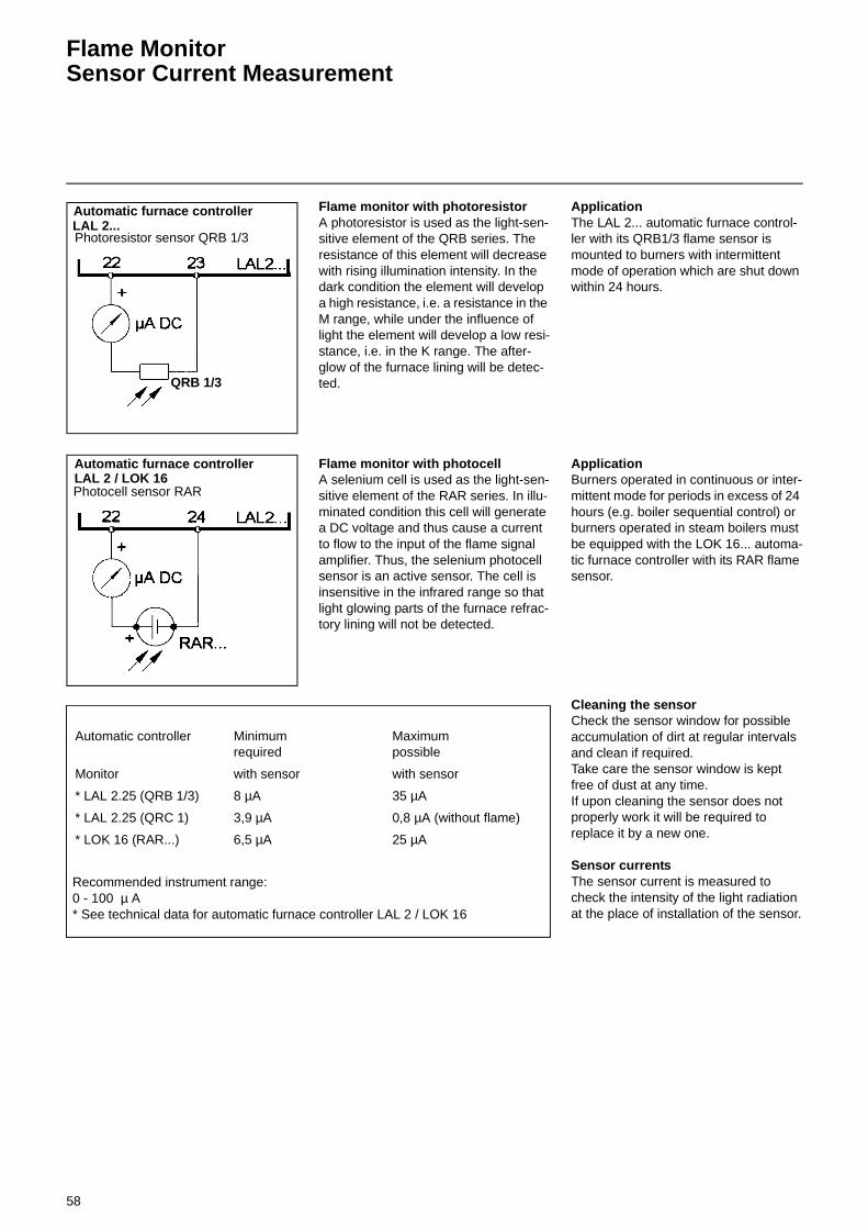
58
Flame Monitor Sensor Current Measurement
Flame monitor with photoresistorA photoresistor is used as the light-sen-sitive element of the QRB series. The resistance of this element will decrease with rising illumination intensity. In the dark condition the element will develop a high resistance, i.e. a resistance in the M range, while under the influence of light the element will develop a low resi-stance, i.e. in the K range. The after-glow of the furnace lining will be detec-ted.
Flame monitor with photocellA selenium cell is used as the light-sen-sitive element of the RAR series. In illu-minated condition this cell will generate a DC voltage and thus cause a current to flow to the input of the flame signal amplifier. Thus, the selenium photocell sensor is an active sensor. The cell is insensitive in the infrared range so that light glowing parts of the furnace refrac-tory lining will not be detected.
ApplicationThe LAL 2... automatic furnace control-ler with its QRB1/3 flame sensor is mounted to burners with intermittent mode of operation which are shut down within 24 hours.
ApplicationBurners operated in continuous or inter-mittent mode for periods in excess of 24 hours (e.g. boiler sequential control) or burners operated in steam boilers must be equipped with the LOK 16... automa-tic furnace controller with its RAR flame sensor.
Cleaning the sensorCheck the sensor window for possible accumulation of dirt at regular intervals and clean if required. Take care the sensor window is kept free of dust at any time.If upon cleaning the sensor does not properly work it will be required to replace it by a new one.
Sensor currentsThe sensor current is measured to check the intensity of the light radiation at the place of installation of the sensor.
Automatic furnace controller
Photoresistor sensor QRB 1/3
QRB 1/3
LAL 2...
Automatic furnace controller
Photocell sensor RARLAL 2 / LOK 16
Recommended instrument range: 0 - 100 µ A * See technical data for automatic furnace controller LAL 2 / LOK 16
Automatic controller Minimumrequired
Maximumpossible
Monitor with sensor with sensor
* LAL 2.25 (QRB 1/3) 8 µA 35 µA
* LAL 2.25 (QRC 1) 3,9 µA 0,8 µA (without flame)
* LOK 16 (RAR...) 6,5 µA 25 µA
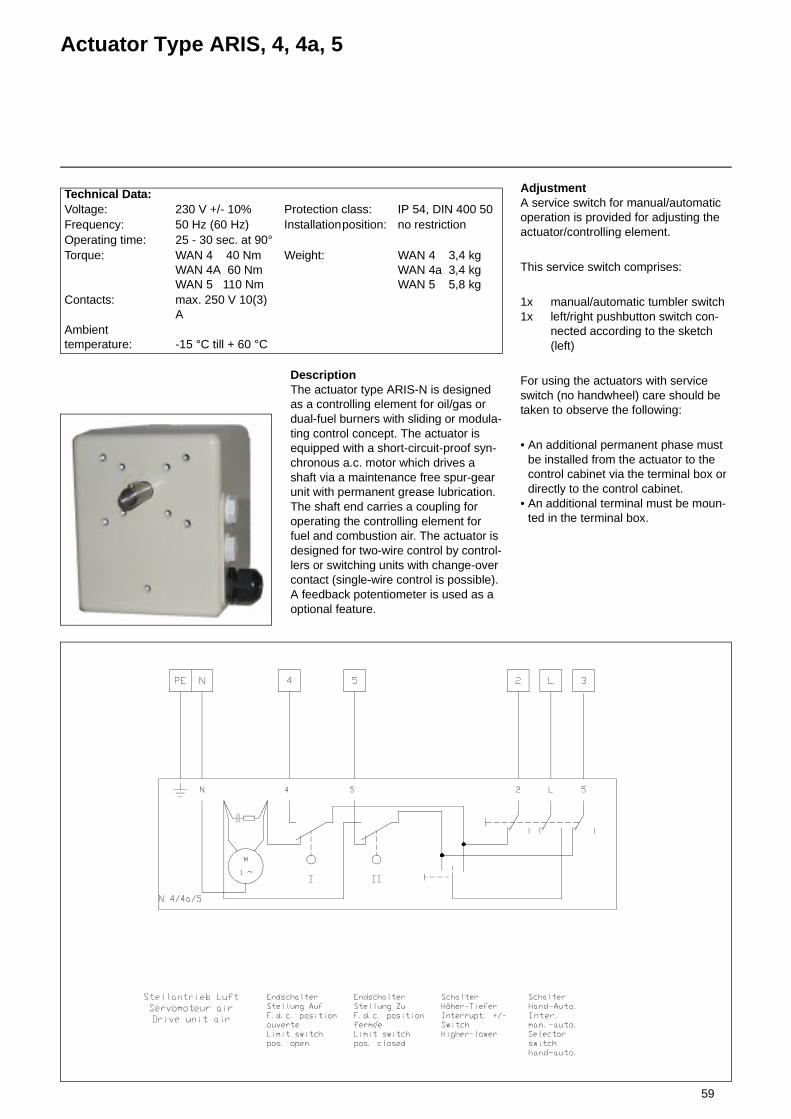
59
Actuator Type ARIS, 4, 4a, 5
DescriptionThe actuator type ARIS-N is designed as a controlling element for oil/gas or dual-fuel burners with sliding or modula-ting control concept. The actuator is equipped with a short-circuit-proof syn-chronous a.c. motor which drives a shaft via a maintenance free spur-gear unit with permanent grease lubrication. The shaft end carries a coupling for operating the controlling element for fuel and combustion air. The actuator is designed for two-wire control by control-lers or switching units with change-over contact (single-wire control is possible). A feedback potentiometer is used as a optional feature.
Technical Data:Voltage: 230 V +/- 10% Protection class: IP 54, DIN 400 50Frequency: 50 Hz (60 Hz) Installation position: no restrictionOperating time: 25 - 30 sec. at 90°Torque: WAN 4 40 Nm
WAN 4A 60 NmWAN 5 110 Nm
Weight: WAN 4 3,4 kgWAN 4a 3,4 kgWAN 5 5,8 kg
Contacts: max. 250 V 10(3) A
Ambient temperature: -15 °C till + 60 °C
AdjustmentA service switch for manual/automatic operation is provided for adjusting the actuator/controlling element.
This service switch comprises:
1x manual/automatic tumbler switch1x left/right pushbutton switch con-
nected according to the sketch (left)
For using the actuators with service switch (no handwheel) care should be taken to observe the following:
• An additional permanent phase must be installed from the actuator to the control cabinet via the terminal box or directly to the control cabinet.
• An additional terminal must be moun-ted in the terminal box.

60
Solenoid Safety Valves
For fuel oil EL, L, M, S according to DIN 51603
TECHNICAL DATA
Function 2/2 electromagnetic safety shut-off valve and rapid action device actuated in oil-firing equipment according to DIN 32725 (DIN EN 264). TÜV tested. Used as well in connec-tion with atomizing oil burners according to DIN 4787 and oil firing systems with steam boilers according to TRD 411.
Nominal diameter 2,5 to 15 mm
Port sizes G1/2
Mounting Direct pipe mounting or with two threaded holes at the lower connection area (please refer to dimensional drawing).
Mounting position Unrestricted
Material specifications Valve body from brass. Internal parts from stainless steel. Bearing plate from ruby and elastomere from oil resistant viton (FKN).
Pressure range Please refer to the table.
Switching times With fuel oil EL and alternating current coils:321 H types: switch-on operation approx. 300 ms,switch-off operation approx. 50 ms 121 G types: switch-on operation approx.50 ms,switch-off operation approx. 20 ms
Media Fuel oil EL, L, M, S (DIN 51603), please refer to the table.
Filter Filters according to DIN 32727 must be connected in series to the 321 H valve
Authorized minimum temperature
Please refer to the table.
Ambient temperature 0 °C to 60 °C
Flow factors kv = 2 to 60 (please refer to the table). The tolerance concerning flow factors is +/- 15 %.
Electrical components 121 G and 321 H types:High temperature and high capacity coil with screw terminal connection.
Coil housing Metallic housing covered with epoxy resin, 360° rotating, with Pg11 cable screwing. System of protection IP 44. Galvanized metallic housing, 360° rotating, with Pg11 cable screwing. System of protection IP 67.
Voltage ( alternating current only )
121 G and 321 H valve types:230 V / 50 Hz - 240 V / 60 Hz (T1)
Voltage tolerances + 10 % to - 10% of the line voltage.
Insulation class H 180 °C for 483824 and 483541coils .
Switch-on time 100 % admissible.
Power rating 9 to 20 Watt (please refer to the table).

61
Solenoid safety valves
321 H typesApplication: safety shut-off valve as rapid action device. Used as well in connection with atomizing oil burners according to DIN 4787 and oil firing systems with steam boilers according to TRD 411. A strainer must be con-nected.
Type:2/2 pre-controlled, closed when de-energized.
121 G typesApplication: safety shut-off valve as rapid action device for use in return pipes of atomizing oil burners accor-ding to DIN 4787 and TRD 411. With regard to current standards this valve must be connected in series with the valve mounted in the supply line (please refer to the schematic dra-wing).
Type:2/2 directly controlled, closed when de-energized by spring force.When the solenoid valve is de-energi-zed the return line medium pressure (against arrow direction) still opens the valve seat until 0,15 bar.
arrow stamped on the valve body

62
Solenoid safety valvesP
ort s
ize
G
Nom
inal
dia
met
er
mm
Kv
l/min
Pre
ssur
e ra
nge
bar
Med
ium
tem
pera
ture
°C
For fuel oil(DIN 51603)
TÜV tested
certified byDIN reg.-no.
Order no.
Pow
er r
atin
gdu
ring
oper
atio
n
Sys
tem
of p
rote
ctio
nD
IN 4
0050
EL L M S Vanne Cage Bobine Watt AC
pre-controlled solenoid valves, closed when de-energized
1/2 15 60 0-300 to
+160x x x x 1x19689 S 321 H 2523
8760.238520.23
483824T1 20IP 44IP 67
Strainers must be ordered separately Order no. type 3/8" : 481159 type 1/2" : 481209
Directly controlled solenoid valves for the return line, closed when de-energized
1/2 14251
252
to 301
0-0,22
0 to
+160x x x x 5 S 023/92 121 G 2523
8760.238520.23
483824T1 20IP 44IP 67
1 Pmax static in the direction of the safety shut-off valve 2 if the flow is in arrow direction (irrelevant with this application)
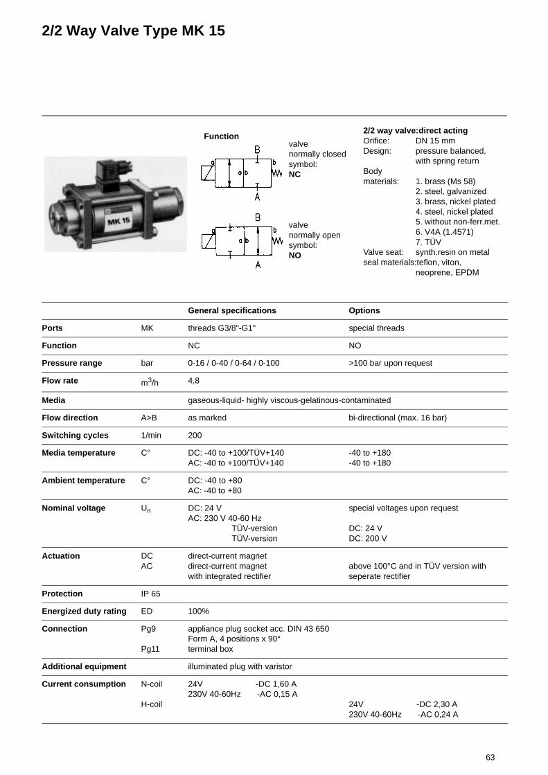
63
2/2 Way Valve Type MK 15
General specifications Options
Ports MK threads G3/8"-G1" special threads
Function NC NO
Pressure range bar 0-16 / 0-40 / 0-64 / 0-100 >100 bar upon request
Flow rate m3/h 4,8
Media gaseous-liquid- highly viscous-gelatinous-contaminated
Flow direction A>B as marked bi-directional (max. 16 bar)
Switching cycles 1/min 200
Media temperature C° DC: -40 to +100/TÜV+140AC: -40 to +100/TÜV+140
-40 to +180-40 to +180
Ambient temperature C° DC: -40 to +80AC: -40 to +80
Nominal voltage Un DC: 24 VAC: 230 V 40-60 Hz TÜV-version TÜV-version
special voltages upon request
DC: 24 VDC: 200 V
Actuation DCAC
direct-current magnetdirect-current magnetwith integrated rectifier
above 100°C and in TÜV version with seperate rectifier
Protection IP 65
Energized duty rating ED 100%
Connection Pg9
Pg11
appliance plug socket acc. DIN 43 650Form A, 4 positions x 90°terminal box
Additional equipment illuminated plug with varistor
Current consumption N-coil
H-coil
24V -DC 1,60 A230V 40-60Hz -AC 0,15 A
24V -DC 2,30 A230V 40-60Hz -AC 0,24 A
Functionvalvenormally closedsymbol:NC
valvenormally opensymbol:NO
2/2 way valve:direct actingOrifice: DN 15 mmDesign: pressure balanced,
with spring returnBody materials: 1. brass (Ms 58)
2. steel, galvanized3. brass, nickel plated4. steel, nickel plated5. without non-ferr.met.6. V4A (1.4571)7. TÜV
Valve seat: synth.resin on metalseal materials:teflon, viton,
neoprene, EPDM
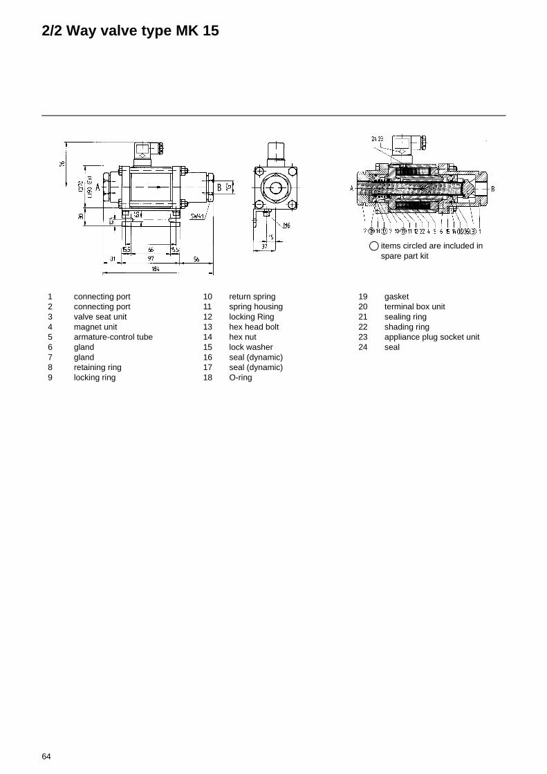
64
2/2 Way valve type MK 15
items circled are included in spare part kit
1 connecting port2 connecting port3 valve seat unit4 magnet unit5 armature-control tube6 gland7 gland8 retaining ring9 locking ring
10 return spring11 spring housing12 locking Ring13 hex head bolt14 hex nut15 lock washer16 seal (dynamic)17 seal (dynamic)18 O-ring
19 gasket20 terminal box unit21 sealing ring22 shading ring23 appliance plug socket unit24 seal

65
2/2 Way Valve Type MK 20
General specifications Options
Ports MK threads G3/4"-G11/4" special threads
Function NC NO
Pressure range bar 0-16 / 0-40 / 0-64 / 0-100 >100 bar upon request
Flow rate m3/h 7,4
Media gaseous-liquid- highly viscous-gelatinous-contaminated
Flow direction A>B as marked bi-directional (max. 16 bar)
Switching cycles 1/min 150
Media temperature C° DC: -40 to +100/TÜV+140AC: -40 to +100/TÜV+140
-40 to +180-40 to +180
Ambient temperature C° DC: -40 to +80AC: -40 to +80
Nominal voltage Un DC: 24 VAC: 230 V 40-60 Hz TÜV-version TÜV-version
special voltages upon request
DC: 24 VDC: 200 V
Actuation DCAC
direct-current magnetdirect-current magnetwith integrated rectifier
above 100°C and in TÜV version with seperate rectifier
Protection IP 65
Energized duty rating ED 100%
Connection Pg9
Pg11
appliance plug socket acc. DIN 43 650Form A, 4 positions x 90°terminal box
Additional equipment illuminated plug with varistor
Current consumption N-coil
H-coil
24V -DC 1,60 A230V 40-60Hz -AC 0,15 A
24V -DC 2,30 A230V 40-60Hz -AC 0,24 A
MK 20
Functionvalvenormally closedsymbol:NC
valvenormally opensymbol:NO
2/2 way valve:direct actingOrifice: DN 20 mmDesign: pressure balanced,
with spring returnBody materials: 1. brass (Ms 58)
2. steel, galvanized3. brass, nickel plated4. steel, nickel plated5. without non-ferr.met.6. V4A (1.4571)7. TÜV
Valve seat: synth.resin on metalseal materials:teflon, viton,
neoprene, EPDM

66
2/2 Way valve type MK 20
General operating instructionsTo ensure the proper operation of our maintenance-free units care should be taken to observe the following points:
1. Prior to installing the valve in the pipeline system make a check that the latter system is absolutely clean to avoid that any particles left behind by the line mounting work can be flushed into the valve when taking the system into ope-ration.
2. Valves with threaded connections should be installed to the pipeline system in a way that the frictional connection is not made in the lon-gitudinal axis of the valve. For screwing in the pipe, the mounting tool should be attached to the valve socket to which the pipe is mounted. For valves with flanged connection, care should be taken that no tensile, compressive and shearing loads are brought to bear on the valve because this could lead to functional trouble. The direction of flow indicated on the 2/2-way valves by arrows should in any case be adhered to.
3. For the electrical connection, uns-crew the terminal box cover or install the plug connectors. Prior to connecting the cables check that the voltage applied is as stated on the rating plate. Take care to observe the marking atta-ched to the terminal because if the connections are wrongly fitted this may cause damage to the valve when taken into operation.
items circled are included in spare part kit
1 connecting port2 connecting port3 valve seat unit4 magnet unit5 armature-control tube6 gland7 gland8 retaining ring9 locking ring
10 return spring11 spring housing12 locking Ring13 hex head bolt14 hex nut15 lock washer16 seal (dynamic)17 seal (dynamic)18 O-ring
19 gasket20 terminal box unit21 sealing ring22 shading ring23 appliance plug socket unit24 seal

67
Pipe spring - Glycerine - ManometerBimetal - Pointer - Temperature controller
Pipe spring - Glycerine - ManometerRF 63 - D 701
Port size G 1/4 A radialHousing from refined steel 1.4301Diameter 63 mm Class 1.6
Scale range Order no.
0 - 6 bar -
0 - 10 bar -
0 - 16 bar -
0 - 25 bar 3333 261 128
0 - 40 bar 109 016 0374
0 - 60 bar 109 811 4290
0 - 100 bar 109 811 4303
Bimetal - Pointer - Temperature controllerTBW 31 H
Measuring instrument: Bi-metallic spiralPort size G 1/4 "Sleeve and locking screw on the back sideHousing CrNi , Shaft length 50 mmDiameter 63 mmClass 1.0Scale range 0 - 160 °COrder no. 109 015 9651
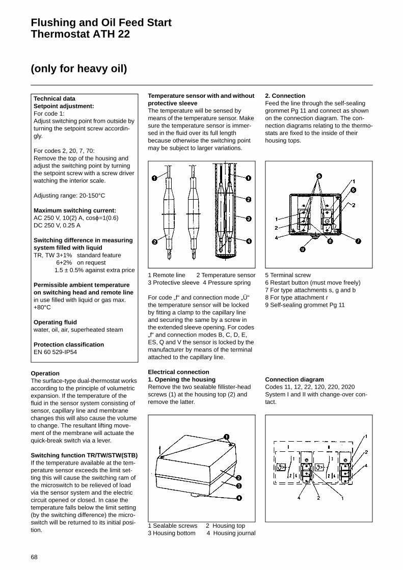
68
Flushing and Oil Feed Start Thermostat ATH 22
(only for heavy oil)
OperationThe surface-type dual-thermostat works according to the principle of volumetric expansion. If the temperature of the fluid in the sensor system consisting of sensor, capillary line and membrane changes this will also cause the volume to change. The resultant lifting move-ment of the membrane will actuate the quick-break switch via a lever.
Switching function TR/TW/STW(STB)If the temperature available at the tem-perature sensor exceeds the limit set-ting this will cause the switching ram of the microswitch to be relieved of load via the sensor system and the electric circuit opened or closed. In case the temperature falls below the limit setting (by the switching difference) the micro-switch will be returned to its initial posi-tion.
Temperature sensor with and without protective sleeveThe temperature will be sensed by means of the temperature sensor. Make sure the temperature sensor is immer-sed in the fluid over its full length because otherwise the switching point may be subject to larger variations.
1 Remote line 2 Temperature sensor3 Protective sleeve 4 Pressure spring
For code „f“ and connection mode „Ü“ the temperature sensor will be locked by fitting a clamp to the capillary line and securing the same by a screw in the extended sleeve opening. For codes „f“ and connection modes B, C, D, E, ES, Q and V the sensor is locked by the manufacturer by means of the terminal attached to the capillary line.
Electrical connection1. Opening the housingRemove the two sealable fillister-head screws (1) at the housing top (2) and remove the latter.
1 Sealable screws 2 Housing top3 Housing bottom 4 Housing journal
2. ConnectionFeed the line through the self-sealing grommet Pg 11 and connect as shown on the connection diagram. The con-nection diagrams relating to the thermo-stats are fixed to the inside of their housing tops.
5 Terminal screw6 Restart button (must move freely)7 For type attachments s, g and b8 For type attachment r9 Self-sealing grommet Pg 11
Connection diagramCodes 11, 12, 22, 120, 220, 2020 System I and II with change-over con-tact.
Technical dataSetpoint adjustment:For code 1:Adjust switching point from outside by turning the setpoint screw accordin-gly.
For codes 2, 20, 7, 70:Remove the top of the housing and adjust the switching point by turning the setpoint screw with a screw driver watching the interior scale.
Adjusting range: 20-150°C
Maximum switching current:AC 250 V, 10(2) A, cosϕ=1(0.6)DC 250 V, 0.25 A
Switching difference in measuring system filled with liquidTR, TW 3+1% standard feature
6+2% on request 1.5 ± 0.5% against extra price
Permissible ambient temperature on switching head and remote linein use filled with liquid or gas max. +80°C
Operating fluidwater, oil, air, superheated steam
Protection classificationEN 60 529-IP54

69
Start-up Light Oil
Checking Procedure
Function of the steplessly controlling light oil burner
The light oil is supplied to the high-pres-sure pump by an oil pump via ring line, gas-air separator and service tank.The light oil is flushed via the pressure control valve on the oil control block. When closing this flushing valve the oil pressure will build up and open the hydraulic ball-type valves in the feed and return lines.The pressure control valve (in oil control block) installed downstream of the high-pressure pump will keep the oil pres-sure at the constant level of 28-30 bar in accordance with an overflow principle. The nozzle rod assembly has 2 connec-tions, the oil feed and the oil return con-nections. Two types of nozzle rods can optionally be used, i.e. the DG75 and the MAT nozzle rods.In the light oil mode it will be possible to actuate the flushing valve, the feed and return valves and the needle-type stop valve in the nozzle rod assembly (in the case of the DG75 type) at the same time.After the nozzle needle valve has ope-ned in the nozzle rod the oil pressure will be controlled via an oil controller in the return line (minimum pressure approx. 3-5 bar; maximum pressure approx. 16-18 bar).If the compound controller is increased to maximum output, the oil pressure will be brought to approx. 16-18 bar (maxi-mum output of nozzle). This output must correspond to the rated output of the heat generator as shown in the nozzle output diagram. Simultaneously with the oil flow rate control, the air flow rate control cam of the compound control system will con-trol the air flow rate required for the combustion of the oil quantity supplied.
Check the following prior to the initial operation of the boiler system:
- Take care to observe the operating instructions supplied by the boiler manufacturer. The boiler must be mounted ready for operation.
- Ensure that the heating system is filled with water.
- Check the complete system for correct electrical wiring.
- Check the air fan and pump motor for correct direction of rotation.
- For checking the direction of rotation of the air fan and pump motors (direct connection) shortly actuate or press the contactor.
- In star-delta connection layouts it will be necessary to actuate the mains and star contactors at the same time.
- Check the correct direction of rotation of the oil pump by comparison with the direction-of-rotation arrow stamped to the pump.
- Check for the proper setting of the temperature and pressure controllers, limiters, safety switches and electrical limit switches.
- Bleed the fuel carrying lines, pumps and pre-heaters (make sure no air is contained).
- Check that the tank, lines and oil pump are filled with oil and that the proper oil nozzle has been fitted.
- Make a test of the hydraulic oil system for absence of leaks.
- Check the exhaust gas ports are ope-ned and sufficient fresh air is taken in.
- With the burner in starting position check that air damper is closed.
- Check that the automatic furnace con-troller is unlocked and in its original position.
Oil start-up
- Open all stop valves of the oil supply system; fill pumps with oil.
- Install feed pressure gauges, vacuum gauges, pumps, etc.
- If a ring line is provided fill this with oil and take it into operation. Check oil temperature.
NOTE: The hydraulic system is factory-filled with test oil which might lead to ignition trouble during initial start-up. To protect the pump the oil pressure con-troller is factory-set at a low pressure only. When starting the burner make sure to increase the oil pressure to ope-rating level gradually.
Prior to initial fuel feed start make a functional test of the burner program flow.
Disconnect the lifting magnet of the nozzle needle valve (solenoid valve) by reference to the wiring diagram.Start the burner and check the program flow for correct sequence of start-up operations.
1. Flush via oil control block.2. Fan.3. Air damper pre-ventilation (check
limit switch setting).4. Check air pressure.5. Air damper starting load (check
limit switch setting).6. Ignition (ignition gas valves).7. Fuel valves.8. Shutdown on trouble after safety
time has run down (see automatic furnace controller).
9. Unlock automatic furnace control-ler.

70
Start-up Heavy Oil
Checking Procedure
Function of the steplessly controlling heavy oil burner
The pumpable heavy oil is supplied to the high-pressure pump by an oil pump via ring line, gas-air separator and ser-vice tank.The high-pressure pump circulates the heavy oil through the preheater, pres-sure control valve and flushing valve of the oil control block. In this process the oil is heated up and brought to atomi-zing viscosity (approx. 12 to 15 cSt). The flushing valve will be closed after the preset oil temperature has been reached. The pressure control valve installed downstream of the high-pressure bur-ner pump will keep the oil pressure at the constant level of 28-30 bar in accor-dance with an overflow principle. The nozzle rod assembly has 2 connec-tions, the oil feed and the oil return con-nections. Two types of nozzle rods can optionally be used, i.e. the DG75 and the MAT nozzle rods.If the DG75 nozzle rod is used, the sole-noid valves will be opened in the feed and return lines for approx. 45 seconds prior to fuel feed start. A flushing pro-cess is started via the nozzle rod and output controller so as to ensure the required fuel oil temperature also imme-diately upstream of the nozzle. A flushing operation is not used with burners having the MAT nozzle rod. In this case the required viscosity is achie-ved by heating the nozzle rod.After the solenoid valves or nozzle needle have opened, the oil pressure will be controlled via an oil controller in the return line (minimum pressure approx. 3-5 bar; maximum pressure approx. 16-18 bar).If the compound controller is increased to maximum output, the oil pressure will be brought to approx. 16-18 bar (maxi-mum output of nozzle). This output must correspond to the rated output of the heat generator as shown in the nozzle output diagram. Simultaneously with the oil flow rate control, the air flow rate control cam of the compound control system will con-trol the air flow rate required for the combustion of the oil quantity supplied.
Check the following prior to the initial operation of the boiler system:
- Take care to observe the operating instructions supplied by the boiler manufacturer. The boiler must be mounted ready for operation.
- Ensure that the heating system is filled with water.
- Check the complete system for correct electrical wiring.
- Check the air fan and pump motor for correct direction of rotation.
- For checking the direction of rotation of the air fan and pump motors (direct connection) shortly actuate or press the contactor.In star-delta connection layouts it will be necessary to actuate the mains and star contactors at the same time. Check the correct direction of rotation of the oil pump by comparison with the direction-of-rotation arrow stamped to the pump.
- Check for the proper setting of the temperature and pressure controllers, limiters, safety switches and electrical limit switches.
- Bleed the fuel carrying lines, pumps and pre-heaters (make sure no air is contained).
- Check that the tank, lines and oil pump are filled with oil and that the proper oil nozzle has been fitted.
- Make a test of the hydraulic oil system for absence of leaks.
- Check the exhaust gas ports are ope-ned and sufficient fresh air is taken in.
- With the burner in starting position check that air damper is closed.
- Check that the automatic furnace con-troller is unlocked and in its original position.
Oil start-up
- Open all stop valves of the oil supply system; fill pumps with oil.
- Install feed pressure gauges, vacuum gauges, pumps, etc.
- If a ring line is provided fill this with oil and take it into operation. Check oil temperature (min. 50-60°C depending on viscosity).
NOTE: The hydraulic system is factory-filled with test oil which might lead to ignition trouble during initial start-up. To protect the pump the oil pressure con-troller is factory-set at a low pressure only. When starting the burner make sure to increase the oil pressure to ope-rating level gradually.
Prior to initial fuel feed start make a functional test of the burner program flow.
Disconnect the lifting magnet of the nozzle needle valve (solenoid valve) by reference to the wiring diagram.Start the burner and check the program flow for correct sequence of start-up operations.
1. Flushing (oil temperature).2. Fan.3. Air damper pre-ventilation (check
limit switch setting).4. Check air pressure.5. Air damper starting load (check
limit switch setting).6. Ignition (ignition gas valves).7. Fuel valves.8. Shutdown on trouble after safety
time has run down (see automatic furnace controller).
9. Unlock automatic furnace control-ler.

71
Viscosity as a Function of Oil Temperature
Temperature [°F]
Kin
emat
ic v
isco
sity
ν [
mm
²/s
= cS
t] Max. feeding viscosity
Maximum viscosity of heavy fuel oil acc. to DIN 51 603
Failure of heavy fuel oil
Temperature [°C]
max. Atomizing viscosity heavy fuel oil
Maximum
viscosity of fuel oil grade EL
acc to DIN 51603
usual feeding viscosity: 60 - 100 cStusual atomizing viscosity: 10 cSt

72
Oil Start-upBurner ShutdownMeasures in Case of Trouble
Oil start-up• Set the emergency and main switches
to „ON“.• Open all stop valves in the oil supply
system. If a ring line system is provi-ded for oil supply the ring line pump must be started.
• Set the fuel selector switch to the „Oil“ position.
• Set the control switch to position „1“. • Set the output selector switch to posi-
tion „0“ (= partial load) or „1“ (= regula-ting load). Select the „regulating load“ position for adjusting the burner.
• The „Manual/Automatic“ selector switch must be in its „Automatic“ posi-tion during the start-up phase and during operation.
• Change over to „Manual“ mode for adjusting the burner.
• Unlock the automatic furnace control-ler. The burner will start in accordance with the program flow of the automatic furnace controller. The burner is in operation now.
Burner shutdown1. Set the control switch to position
„0“.2. Set the fuel selector switch to
position „0“.3. Close the oil stop valves.4. For short periods of shutdown the
fuel stop valves may remain in their open positions.
5. For longer periods of shutdown and for inspections make sure to set all switches to their „OFF“ positions and close all oil stop val-ves.
6. Have the furnace system inspec-ted at least once a year by the local service company to ensure its efficient operation and com-pliance with the applicable air pol-lution control regulations.
7. Oil combustion should be without the development of smoke and the flame should burn steadily wit-hout the formation of soot. No visi-ble smoke must emerge from the chimney and no smell of oil must occur.
8. Any conditions deviating from standards and any faults should immediately be reported to the installer of the system and elimi-nated without delay.
Measures in case of troubleBurner trouble will be indicated by the illuminated pushbutton switch (red light) in the control cabinet or automatic fur-nace controller. As soon as the trouble is eliminated the automatic furnace con-troller can be unlocked by pressing any of the two illuminated pushbutton swit-ches which causes the burner to start in accordance with the program. If the bur-ner changes over to the trouble position again, call in the local service company.
Regular checks and maintenance measures• Check the oil pressure on the pressure
gauge.• Check the safety time of the automatic
furnace controller by pulling out the UV flame monitor.
• The safety time must be 5 seconds for start-up while during normal operation the burner must be shut down without delay.
• Clean the flame sensors if dirt has accumulated.
• Clean all filters at regular intervals and check for tight condition. Clean the oil filter each time a fresh oil supply has been taken in. Rinse the filter with pure benzine or similar solvent and blow out with compressed air. Remove residual dirt from filter housing, if any.

73
Exhaust Gas Test
Exhaust gas testTo ensure an economically efficient and trouble-free operation of the system it will be necessary to adjust the burner specifically in accordance with the furnace system. This is achieved by means of a fuel-combustion air compound control unit which adjusts the burner to ensure a proper combustion. Exhaust gas tests are required for this purpose. The percentage CO2 and O2 and the exhaust gas temperature will have to be measured to determine the efficiency and combustion quality.Prior to any measurement make sure to check the boiler and exhaust gas system for absence of leaks.
Secondary air will falsify the measured resultsCheck that the exhaust gases have a residual oxy-gen (O2) content as low as possible and a carbon dioxide (CO2) content as high as possible.The carbon monoxide content of the exhaust gases must be below the currently applicable specificati-ons in all load stages.In the fuel oil combustion mode the permissible soot number in the exhaust gas is not allowed to be exceeded.
Ratio between O2- and CO2- for light oil EL (CO2max =15,40%)
% O2 % CO2 % O2 % CO2
0,00 15,40 3,00 13,190,10 15,33 3,10 13,120,20 15,25 3,20 13,040,30 15,18 3,30 12,970,40 15,11 3,40 12,890,50 15,03 3,50 12,820,60 14,96 3,60 12,750,70 14,88 3,70 12,670,80 14,81 3,80 12,600,90 14,74 3,90 12,531,00 14,66 4,00 12,451,10 14,59 4,10 12,381,20 14,52 4,20 12,311,30 14,44 4,30 12,231,40 14,37 4,40 12,161,50 14,29 4,50 12,081,60 14,22 4,60 12,011,70 14,15 4,70 11,941,80 14,07 4,80 11,861,90 14,00 4,90 11,792,00 13,93 5,00 11,722,10 13,85 5,10 11,642,20 13,78 5,20 11,572,30 13,71 5,30 11,492,40 13,63 5,40 11,422,50 13,56 5,50 11,352,60 13,48 5,60 11,272,70 13,41 5,70 11,202,80 13,34 5,80 11,132,90 13,26 5,90 11,05
O2 21CO2max CO2gem–
CO2max-----------------------------------------------× %==O2 21CO2max CO2gem–
CO2max-----------------------------------------------× %==
Ratio between O2- and CO2- forheavy oil (CO2max =15,90%)
% O2 % CO2 % O2 % CO2
0,00 15,90 3,00 13,630,10 15,82 3,10 13,550,20 15,75 3,20 13,480,30 15,67 3,30 13,400,40 15,60 3,40 13,330,50 15,52 3,50 13,250,60 15,45 3,60 13,170,70 15,37 3,70 13,100,80 15,29 3,80 13,020,90 15,22 3,90 12,951,00 15,14 4,00 12,871,10 15,07 4,10 12,801,20 14,99 4,20 12,721,30 14,92 4,30 12,641,40 14,84 4,40 12,571,50 14,76 4,50 12,491,60 14,69 4,60 12,421,70 14,61 4,70 12,341,80 14,54 4,80 12,271,90 14,46 4,90 12,192,00 14,39 5,00 12,112,10 14,31 5,10 12,042,20 14,23 5,20 11,962,30 14,16 5,30 11,862,40 14,08 5,40 11,812,50 14,01 5,50 11,742,60 13,93 5,60 11,662,70 13,86 5,70 11,582,80 13,78 5,80 11,512,90 13,70 5,90 11,43
O2 21 2max CO2gem–
CO2max-----------------------------------------× %==

74
SO2-content in Exhaust Gasfrom Light Oil and Heavy Oil Combustion
SO2 -content in exhaust gas from light oil combustion
SO2 -content in exhaust gas from heavy oil combustion
SO2 in dry exhaust gas
Sulphur content in fuel [% by wt.]
CO 2 c
onte
nt in
exh
aust
gas
15%
by
vol.
CO2
[% by vol.]
CO2[% by vol.]
Sulphur content in fuel [% by wt.]
SO2 in dry exhaust gas
CO 2 c
onte
nt in
exh
aust
gas
[% b
y vo
l.]
1,2
% b
y w
t.
2,8
% b
y w
t.= m
ax. a
cc.
to D
IN 5
1 60
3

75
O2, CO2, Lambda Conversion Table
Light Fuel Oil
Relation between O2 and CO2 value for light fuel oil (CO2max=15,4 %)
%O2 %CO2 Air index
0,00 15,40 1,000,10 15,33 1,00
0,20 15,25 1,010,30 15,18 1,010,40 15,11 1,02
0,50 15,03 1,020,60 14,96 1,030,70 14,89 1,03
0,80 14,81 1,040,90 14,74 1,04
1,00 14,67 1,051,10 14,59 1,061,20 14,52 1,06
1,30 14,45 1,071,40 14,37 1,071,50 14,30 1,08
1,60 14,23 1,081,70 14,15 1,091,80 14,08 1,09
1,90 14,01 1,10
2,00 13,93 1,11
2,10 13,86 1,112,20 13,79 1,122,30 13,71 1,12
2,40 13,64 1,132,50 13,57 1,142,60 13,49 1,14
2,70 13,42 1,152,80 13,35 1,152,90 13,27 1,16
3,00 13,20 1,173,10 13,13 1,17
3,20 13,05 1,183,30 12,98 1,193,40 12,91 1,19
3,50 12,83 1,203,60 12,76 1,213,70 12,69 1,21
3,80 12,61 1,223,90 12,54 1,23
O2 21CO2max CO2gem–
CO2max-----------------------------------------------× %==
%O2 %CO2 Air index
4,00 12,47 1,244,10 12,39 1,24
4,20 12,32 1,254,30 12,25 1,264,40 12,17 1,27
4,50 12,10 1,274,60 12,03 1,284,70 11,95 1,29
4,80 11,88 1,304,90 11,81 1,30
5,00 11,73 1,315,10 11,66 1,325,20 11,59 1,33
5,30 11,51 1,345,40 11,44 1,355,50 11,37 1,35
5,60 11,29 1,365,70 11,22 1,375,80 11,15 1,38
5,90 11,07 1,39
6,00 11,00 1,40
6,10 10,93 1,416,20 10,85 1,426,30 10,78 1,43
6,40 10,71 1,446,50 10,63 1,456,60 10,56 1,46
6,70 10,49 1,476,80 10,41 1,48
6,90 10,34 1,49
7,00 10,27 1,50
7,10 10,19 1,517,20 10,12 1,527,30 10,05 1,53
7,40 9,97 1,547,50 9,90 1,567,60 9,83 1,57
7,70 9,75 1,587,80 9,68 1,597,90 9,61 1,60
%O2 %CO2 Air index
8,00 9,53 1,628,10 9,46 1,63
8,20 9,39 1,648,30 9,31 1,658,40 9,24 1,67
8,50 9,17 1,688,60 9,09 1,698,70 9,02 1,71
8,80 8,95 1,728,90 8,87 1,74
9,00 8,80 1,759,10 8,73 1,769,20 8,65 1,78
9,30 8,58 1,799,40 8,51 1,819,50 8,43 1,83
9,60 8,36 1,849,70 8,29 1,869,80 8,21 1,87
9,90 8,14 1,89
10,00 8,07 1,91
10,10 7,99 1,9310,20 7,92 1,9410,30 7,85 1,96
10,40 7,77 1,9810,50 7,70 2,0010,60 7,63 2,02
10,70 7,55 2,0410,80 7,48 2,06
10,90 7,41 2,08
11,00 7,33 2,10
11,10 7,26 2,1211,20 7,19 2,1411,30 7,11 2,16
11,40 7,04 2,1911,50 6,97 2,2111,60 6,89 2,23
11,70 6,82 2,2611,80 6,75 2,2811,90 6,67 2,31
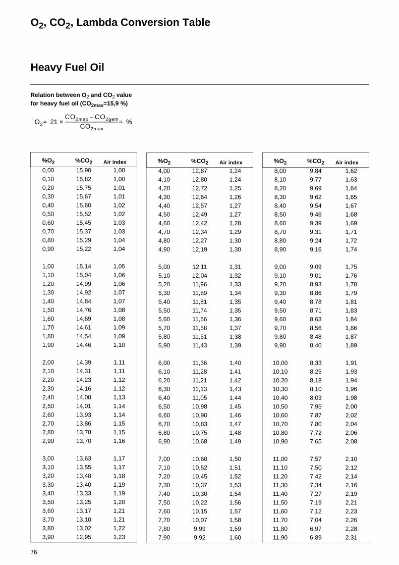
76
O2, CO2, Lambda Conversion Table
Heavy Fuel Oil
Relation between O2 and CO2 value for heavy fuel oil (CO2max=15,9 %)
%O2 %CO2 Air index
0,00 15,90 1,00
0,10 15,82 1,000,20 15,75 1,010,30 15,67 1,01
0,40 15,60 1,020,50 15,52 1,020,60 15,45 1,03
0,70 15,37 1,030,80 15,29 1,040,90 15,22 1,04
1,00 15,14 1,051,10 15,04 1,06
1,20 14,99 1,061,30 14,92 1,071,40 14,84 1,07
1,50 14,76 1,081,60 14,69 1,081,70 14,61 1,09
1,80 14,54 1,091,90 14,46 1,10
2,00 14,39 1,112,10 14,31 1,112,20 14,23 1,12
2,30 14,16 1,122,40 14,08 1,13
2,50 14,01 1,142,60 13,93 1,142,70 13,86 1,15
2,80 13,78 1,152,90 13,70 1,16
3,00 13,63 1,173,10 13,55 1,173,20 13,48 1,18
3,30 13,40 1,193,40 13,33 1,193,50 13,25 1,20
3,60 13,17 1,213,70 13,10 1,213,80 13,02 1,22
3,90 12,95 1,23
O2 21CO2max CO2gem–
CO2max-----------------------------------------------× %==
%O2 %CO2 Air index
4,00 12,87 1,244,10 12,80 1,244,20 12,72 1,25
4,30 12,64 1,264,40 12,57 1,274,50 12,49 1,27
4,60 12,42 1,284,70 12,34 1,294,80 12,27 1,30
4,90 12,19 1,30
5,00 12,11 1,31
5,10 12,04 1,325,20 11,96 1,335,30 11,89 1,34
5,40 11,81 1,355,50 11,74 1,355,60 11,66 1,36
5,70 11,58 1,375,80 11,51 1,385,90 11,43 1,39
6,00 11,36 1,406,10 11,28 1,41
6,20 11,21 1,426,30 11,13 1,436,40 11,05 1,44
6,50 10,98 1,456,60 10,90 1,46
6,70 10,83 1,476,80 10,75 1,486,90 10,68 1,49
7,00 10,60 1,507,10 10,52 1,51
7,20 10,45 1,527,30 10,37 1,537,40 10,30 1,54
7,50 10,22 1,567,60 10,15 1,577,70 10,07 1,58
7,80 9,99 1,597,90 9,92 1,60
%O2 %CO2 Air index
8,00 9,84 1,628,10 9,77 1,638,20 9,69 1,64
8,30 9,62 1,658,40 9,54 1,678,50 9,46 1,68
8,60 9,39 1,698,70 9,31 1,718,80 9,24 1,72
8,90 9,16 1,74
9,00 9,09 1,75
9,10 9,01 1,769,20 8,93 1,789,30 8,86 1,79
9,40 8,78 1,819,50 8,71 1,839,60 8,63 1,84
9,70 8,56 1,869,80 8,48 1,879,90 8,40 1,89
10,00 8,33 1,9110,10 8,25 1,93
10,20 8,18 1,9410,30 8,10 1,9610,40 8,03 1,98
10,50 7,95 2,0010,60 7,87 2,02
10,70 7,80 2,0410,80 7,72 2,0610,90 7,65 2,08
11,00 7,57 2,1011,10 7,50 2,12
11,20 7,42 2,1411,30 7,34 2,1611,40 7,27 2,19
11,50 7,19 2,2111,60 7,12 2,2311,70 7,04 2,26
11,80 6,97 2,2811,90 6,89 2,31

77
Exhaust Gas Test
Trouble Shooting Instructions
Exhaust gas lossExhaust gas loss by way of free heat will occur as a result of the temperature difference between the fuel-air mixture entering the furnace chamber and the gases discharged. Any increase in the excess of air and the resultant higher exhaust gas volume will cause the exhaust gas loss to rise. The exhaust gas loss can be calculated as follows:
Example:Data measured in fuel oil mode:CO2 content of exhaust gases 12,8%Exhaust gas temperature 195°CAir intake temperature 22°C
The exhaust gas loss can be calculated as follows:
q A = exhaust gas loss in %t A = exhaust gas temperature
in °Ct L = combustion air temperature
in °CCO2= volumetric content of carbon
dioxide in %
qA tA tL–( )A1
CO2----------- B+
⋅=
Light oilEL
Heavy oilS
A1 = 0,50 0,490
B = 0,007 0,007
In any case of trouble proceed with checking the basic conditions for a proper operation of the boiler system:1.Is electric power available?2.Is fuel oil contained in the tank?3.Are the shut-off valves opened?4.Are all control and safety instruments
such as boiler thermostat, water supply failure cut-out, limit switches,
etc. properly set?
1. Ignition failure
Cause Remedy
Ignition elec-trode short cir-cuit.
Adjust electrodes.
Wide ignition electrode spacing.
Adjust electrodes.
Dirty and wet electrodes.
Clean electrodes.
Cracked insulator.
Replace insulator.
Defective igni-tion transformer.
Replace transformer.
Defective auto-matic furnace controller.
Replace controller.
Burnt ignition cable.
Replace cable; search for cause and eliminate.
Pilot burner failure.
Adjust ignition gas pressure
Ignition gas valve does not open.
Search for cause and elimi-nate
Defective solenoid.
Replace
2. Motor running failure
Cause Remedy
Motor protection relay and fuses.
Check and replace if required.
Air pressure switch not changed over or defective.
Check and replace if required.
Defective motor. Replace motor.
Defective power contactor.
Replace contactor.
Air fan motor starts but stops after 20-25 secs.
Check for solenoid leaks
Air fan motor starts, but stops after about 10 secs in pre-venti-lating mode.
Air pressure switch fails to change over; replace switch if defective; clean switch if dirt has accumulated; check electrical connections.
3. Pump oil delivery failure
Cause Remedy
Shut-off valves closed.
Open valves.
Filter blocked by dirt.
Clean filter or replace cartridge.
Filter leaks. Replace filter
Oil lines leak. Retighten scre-wed unions; tigh-ten oil lines.
Suction valve leaks.
Remove and clean or replace.
Direction of rota-tion of pump.
Check irection of rotation.
Damaged gear-box.
Replace pump.
Reduced pump output.
Replace pump.
-Strong mechanical noise.
Pump takes in air Retighten scre-wed unions.
High vacuum in oil pipe
Clean filter; fully open valves.
For heavy oil:Incorrect oil tem-perature.
Check pre-hea-ter: thermostat set-ting, dirt

78
Trouble Shooting Instructions
8. Cleaning and lubricating instructionsDepending on the amount of dirt intro-duced by the combustion air it will be necessary to clean the fan impeller, ignition electrodes, flame sensors and air dampers as required.
For burner with mechanical compound controller:Lubricate the ball heads of the com-pound controller setting screws with grease.
The bearing points of the burner moving parts require no maintenance.Damages of ball bearings should be detected and eliminated at an early stage to avoid greater subsequent trouble. Listen to the motor bearing noise to identify possible irregularities.
4. Unsteady atomization
Cause Remedy
Loosened nozzle.
Tighten nozzle
Hole partly clog-ged.
Remove and clean or replace.
Worn by long-time use.
Replace by new one.
Oil flow blokkage
Due to clogged nozzle.
Remove and clean.
Nozzle leaking. Replace nozzle.
Shut-off valve in nozzle rod lea-king.
Replace valve.
5. No response to flame by automatic furnace controller with flame sensor
Cause Remedy
Dirty flame sen-sor.
Clean flame sensor.
Burner fails to start.
Check connection of automatic fur-nace controller.
Trouble lamp lights; flame trouble.
Unlock and search for cause
Weak flame sen-sor signals.
Check combus-tion setting.
Burner starts without flame formation. Solenoid valve fails to open.
Defective coil or rectifier. Check connec-tion.
6. Mixing unit gives poor com-bustion data due to heavy insideaccumulation of oil or coke
Cause Remedy
Incorrect set-tings.
Correct settings.
Incorrect mix-ture ignition unit.
Replace unit.
Nozzle too large or too small.
Replace nozzle.
Incorrect angle of spray.
Replace nozzle.
High or low com-bustion air flow rate.
Readjust burner.
Furnace cham-ber not suf-ficiently ventilated.
Furnace cham-ber to be ventila-ted through a non-closed ope-ning with a cross section of min. 50 % of all chim-ney cross sec-tions of the furnace system. Take care to observe the application regu-lations.
7. Solenoid valve fails to open
Cause Remedy
Defective coil. Replace coil.
Defective auto-matic furnace controller.
Replace auto-matic furnace controller.
Valve does not close tightly; dirt accumulated on sealing surfaces.
Open valve; remove foreign matter; replace valve if required.

44
Customer Service:
ECB GmbHStruppener Strasse01796 Pirna