operation manual - iwatsu
TRANSCRIPT
Operation ManualOperation Manual

ii
IntroductionIntroduction
•• Thank you for purchasing this IWATSU instrument.Thank you for purchasing this IWATSU instrument.
•• Please read this manual before using the instrument, then keep the manual handy forPlease read this manual before using the instrument, then keep the manual handy forfuture reference.future reference.
•• To ensure safe operation of this instrument and to prevent injury to the user or damageTo ensure safe operation of this instrument and to prevent injury to the user or damageto property, read and carefully observe the warnings and cautions in the followingto property, read and carefully observe the warnings and cautions in the followingsection.section.
•• This operation manual mainly describes notes on use, operation method, examples ofThis operation manual mainly describes notes on use, operation method, examples ofuse and performance of this instrument and remote control of RS-232C and GP-IB.use and performance of this instrument and remote control of RS-232C and GP-IB.
NoteNote
•• Parts of the contents of this manual may be modified without notice for improvementsParts of the contents of this manual may be modified without notice for improvementsin performance and functions.in performance and functions.
•• Reproduction or reprinting of the contents of this manual without prior permissionReproduction or reprinting of the contents of this manual without prior permissionfrom IWATSU is prohibited.from IWATSU is prohibited.
•• The TFT color LCD contains cold cathode fluorescent lamps. Observe local ordinancesThe TFT color LCD contains cold cathode fluorescent lamps. Observe local ordinancesand regulations when disposing of the LCD.and regulations when disposing of the LCD.
•• Windows and MS-DOS are registered trademarks of Microsoft Corporation.Windows and MS-DOS are registered trademarks of Microsoft Corporation.
•• For questions about this instrument, contact IWATSU at the address listed at the endFor questions about this instrument, contact IWATSU at the address listed at the endof this manual or our sales agent.of this manual or our sales agent.
Revision HistoryRevision History
November 1999November 1999 :: 1st edition1st edition
May 2000May 2000 :: 2nd edition2nd edition
KML037621KML037621 A1-212500(B)A1-212500(B)

iiii
Safety precautionsSafety precautions
To ensure safe operation of this instrument and to prevent injury to the user or damageTo ensure safe operation of this instrument and to prevent injury to the user or damageto property, read and carefully observe the warnings and cautions in the following sectionto property, read and carefully observe the warnings and cautions in the following sectionand associated symbols marked on the panel diagrams.and associated symbols marked on the panel diagrams.
Definitions of warnings and cautions used in this manualDefinitions of warnings and cautions used in this manual
STAND BYSTAND BY:: Standby mode is set when the main power supply of this instrument isStandby mode is set when the main power supply of this instrument isturned OFF.turned OFF.
Explanation of the symbols on the panelExplanation of the symbols on the panel
Symbol Symbol DescriptionDescription
Symbols used throughout the manual together with descriptions, to protect theSymbols used throughout the manual together with descriptions, to protect theoperator from injury and this instrument from damage.operator from injury and this instrument from damage.
Indicates that this is a frame or chassis terminal.Indicates that this is a frame or chassis terminal.
Indicates that there is a danger of electric shockIndicates that there is a danger of electric shock
Power ONPower ON
Stand byStand by
Incorrect operation or failure to observe the warning may result in death orIncorrect operation or failure to observe the warning may result in death orserious injury.serious injury.
Incorrect operation or failure to observe the caution may result in injury orIncorrect operation or failure to observe the caution may result in injury ordamage to instrument.damage to instrument.CautionCaution
WarningWarning

iiiiii
InstallationInstallation
•• Do not use in an environment with explosive gases. It may cause an explosion.Do not use in an environment with explosive gases. It may cause an explosion.
•• If you notice smoke, foul odor or abnormal noise, immediately stop measuring toIf you notice smoke, foul odor or abnormal noise, immediately stop measuring toavoid electric shock or fire. Turn off the instrument to be measured andavoid electric shock or fire. Turn off the instrument to be measured anddisconnect the power cable from the power outlet. Please contact IWATSU atdisconnect the power cable from the power outlet. Please contact IWATSU atthe address listed at the end of this manual or our sales agent. Do not attempt tothe address listed at the end of this manual or our sales agent. Do not attempt torepair the unit yourself.repair the unit yourself.
Power SupplyPower Supply
•• Always use this instrument only within the rated operating voltage. If usedAlways use this instrument only within the rated operating voltage. If usedover the rated range, electric shock, fire or failure may occur. The range ofover the rated range, electric shock, fire or failure may occur. The range ofoperating voltage is stated on the rear panel.operating voltage is stated on the rear panel.This instrument runs on single-phase, 115 V (90 to 132 V) or 220 V (180 toThis instrument runs on single-phase, 115 V (90 to 132 V) or 220 V (180 to250 V), AC power source at 45 to 66 Hz. No voltage selection is required, as250 V), AC power source at 45 to 66 Hz. No voltage selection is required, asthe instrument automatically adapts to the line voltage.the instrument automatically adapts to the line voltage.
•• Use a 3-prong grounded power cord. By connecting the attached 3-prong powerUse a 3-prong grounded power cord. By connecting the attached 3-prong powercord to a 3-wire receptacle, the grounding wire of the power cord is connectedcord to a 3-wire receptacle, the grounding wire of the power cord is connectedto ground. If this is not done, an electric shock or instrument damage couldto ground. If this is not done, an electric shock or instrument damage couldresult. When supplying power from a 2-wire receptacle using a 3-prong/2-prongresult. When supplying power from a 2-wire receptacle using a 3-prong/2-prongconversion adapter, connect the grounding terminal of the 3-prong/2-prongconversion adapter, connect the grounding terminal of the 3-prong/2-prongconversion adapter to ground.conversion adapter to ground.
•• Use of a 2-prong power cord may result in electric shock.Use of a 2-prong power cord may result in electric shock.
If the supply voltage is of a 200 V system (200 V to 240 V), use a 200 V systemIf the supply voltage is of a 200 V system (200 V to 240 V), use a 200 V system(rated 250 V) 3-prong power cord.(rated 250 V) 3-prong power cord.
Read the following safety information.Read the following safety information.
WarningsWarnings

iviv
Read the following safety information.Read the following safety information.
When measuringWhen measuring
•• Connect the probe ground and input connectors to the ground of the deviceConnect the probe ground and input connectors to the ground of the deviceunder test. Refer to “improper ground connections” shown below. Improperunder test. Refer to “improper ground connections” shown below. Improperground connections may cause electric shock or failure of the instrument, theground connections may cause electric shock or failure of the instrument, thedevice under test or other devices connected to the instrument.device under test or other devices connected to the instrument.
[Improper ground connections][Improper ground connections]
When measuring a floating potential, measurement by the differential methodWhen measuring a floating potential, measurement by the differential method(CH1, CH2 input) is recommended as shown in the example below.(CH1, CH2 input) is recommended as shown in the example below.
[Example of recommended measurement][Example of recommended measurement]
WarningsWarnings
•• Power cordPower cord
Do not use a damaged power cord or adapter, otherwise fire or electric shockDo not use a damaged power cord or adapter, otherwise fire or electric shockcould result. If the power cord is damaged, please contact IWATSU at the addresscould result. If the power cord is damaged, please contact IWATSU at the addresslisted at the end of this manual or our sales agent for repair.listed at the end of this manual or our sales agent for repair.
•• Do not modify the power cord.Do not modify the power cord. •• Do not pull the power cord.Do not pull the power cord.•• Do not forcibly bend the power cord.Do not forcibly bend the power cord. •• Do not heat the power cord.Do not heat the power cord.•• Do not twist the power cord.Do not twist the power cord. •• Do not let the power cord get wet.Do not let the power cord get wet.•• Do not bundle the power cord.Do not bundle the power cord.•• Do not put heavy objects on the power cord.Do not put heavy objects on the power cord.

vv
OperationOperation
•• Make sure no water gets on or inside the productMake sure no water gets on or inside the product
•• Do not use the product if wet, otherwise electric shock or fire could result. IfDo not use the product if wet, otherwise electric shock or fire could result. Ifwater gets on or inside the unit, turn the power switch to STBY and remove thewater gets on or inside the unit, turn the power switch to STBY and remove thepower cord. Immediately contact IWATSU at the address listed at the end ofpower cord. Immediately contact IWATSU at the address listed at the end ofthis manual or our sales agent.this manual or our sales agent.
•• Do not touch the plug of the power cord with wet hands, otherwise electricDo not touch the plug of the power cord with wet hands, otherwise electricshock could result.shock could result.
•• Operate the instrument on a stable platform. Do not place the instrument on anOperate the instrument on a stable platform. Do not place the instrument on anunstable support. Dropping the instrument during operation could result inunstable support. Dropping the instrument during operation could result inelectric shock, injury, or fire. If the instrument is dropped, turn the power switchelectric shock, injury, or fire. If the instrument is dropped, turn the power switchto STBY and remove the power cord. Immediately contact IWATSU at theto STBY and remove the power cord. Immediately contact IWATSU at theaddress listed at the end of the manual or our sales agent.address listed at the end of the manual or our sales agent.
•• Do not remove the chassis covers or rear panel. Removing covers exposes lethalDo not remove the chassis covers or rear panel. Removing covers exposes lethalhigh-voltage circuits within and could result in electric shock.high-voltage circuits within and could result in electric shock.Please contact IWATSU at the address listed at the end of the manual or ourPlease contact IWATSU at the address listed at the end of the manual or oursales agent for inspection, calibration, or repair.sales agent for inspection, calibration, or repair.
•• Do not modify this instrument. Modification of this instrument could result inDo not modify this instrument. Modification of this instrument could result inelectric shock, fire, or power failure, and repair of a modified instrument mayelectric shock, fire, or power failure, and repair of a modified instrument maybe refused.be refused.
•• Do not operate the instrument in conditions where foreign particles such asDo not operate the instrument in conditions where foreign particles such asmetals or inflammables could pass through the ventilation holes. Operationmetals or inflammables could pass through the ventilation holes. Operationunder these conditions could result in fire, electric shock, or instrument damage.under these conditions could result in fire, electric shock, or instrument damage.If any foreign matter has contaminated the unit, turn the power switch to STBYIf any foreign matter has contaminated the unit, turn the power switch to STBYand remove the power cord. Immediately contact IWATSU at the address listedand remove the power cord. Immediately contact IWATSU at the address listedat the end of the manual or our sales agent.at the end of the manual or our sales agent.
WarningsWarnings
Read the following safety information.Read the following safety information.

vivi
Read the following safety information.Read the following safety information.
InstallationInstallation•• Always use this instrument only within the rated operating range. If used overAlways use this instrument only within the rated operating range. If used over
the rated range, failure may occur.the rated range, failure may occur.Use this instrument only indoors.Use this instrument only indoors.Operating conditionsOperating conditionsTemperature:Temperature: 0 to +40°C0 to +40°CHumidity:Humidity: 80% RH or less (non-condensing)80% RH or less (non-condensing)Height:Height: 2,000 meters or less2,000 meters or less
•• Do not block the air ventilation holes or exhaust fan of this instrument. BlockingDo not block the air ventilation holes or exhaust fan of this instrument. Blockingthe airflow could result in excessive internal heating and fire or electric shock.the airflow could result in excessive internal heating and fire or electric shock.
•• Leave a space behind and to the sides of the instrument.Leave a space behind and to the sides of the instrument.Be careful to avoid overheating of the instrument when installing the instrumentBe careful to avoid overheating of the instrument when installing the instrumentin a rack mount or on another measurement machine. Failing to observe thisin a rack mount or on another measurement machine. Failing to observe thisprecaution may result in faulty operation or performance.precaution may result in faulty operation or performance.
•• Do not place this instrument in a location with excessive moisture or dust,Do not place this instrument in a location with excessive moisture or dust,otherwise fire or electric shock could result.otherwise fire or electric shock could result.
Power SupplyPower Supply•• Use only the specified fuse (Use only the specified fuse (φφ5 5 ×× 20 mm, 250 V, T3.15 A) when replacing the 20 mm, 250 V, T3.15 A) when replacing the
fuse. Failure to replace the fuse with the correct rating could result in fire,fuse. Failure to replace the fuse with the correct rating could result in fire,electric shock or damage to the unit.electric shock or damage to the unit.To replace the fuse:To replace the fuse:a) Turn the power switch to STBY before disconnecting the power cord.a) Turn the power switch to STBY before disconnecting the power cord.b) Disconnect the power cord before replacing the fuse.b) Disconnect the power cord before replacing the fuse.
When measuringWhen measuring
•• Do not apply a voltage exceeding the specified value to the input terminalsDo not apply a voltage exceeding the specified value to the input terminals(CH1, CH2, EXT TRIG). This may cause malfunction. The following is a(CH1, CH2, EXT TRIG). This may cause malfunction. The following is amaximum voltage that can be input.maximum voltage that can be input.
DirectDirect1 M1 MΩΩ : ±400 V (DC+ACpeak: ±400 V (DC+ACpeak≤≤5 k Hz)5 k Hz)When SS-0130R (10:1) equivalent probe is used: ±600 V (DC+ACpeak)When SS-0130R (10:1) equivalent probe is used: ±600 V (DC+ACpeak)
[Note][Note]:: Maximum voltage that can be input may decrease depending on theMaximum voltage that can be input may decrease depending on thefrequency or high voltage pulse of the input signal.frequency or high voltage pulse of the input signal.
•• When a probe or measurement cable is connected, be careful so that you do notWhen a probe or measurement cable is connected, be careful so that you do notpull the probe or measurement cable causing the instrument to overturn.pull the probe or measurement cable causing the instrument to overturn.
Letting the instrument overturn may cause electric shock, injury, fire orLetting the instrument overturn may cause electric shock, injury, fire ormalfunction.malfunction.
CautionsCautions

viivii
Read the following safety information.Read the following safety information.
HandlingHandling
•• Set the power switch to STAND BY before connecting or disconnecting theSet the power switch to STAND BY before connecting or disconnecting thepower cord.power cord.
•• Connecting or disconnecting the power cord while the power is supplied to theConnecting or disconnecting the power cord while the power is supplied to theinstrument may cause electric shock or malfunction.instrument may cause electric shock or malfunction.
•• When disconnecting the power cord from the receptacle, remove it by graspingWhen disconnecting the power cord from the receptacle, remove it by graspingthe plug. Do not pull on the cord itself, as doing so may damage the cord andthe plug. Do not pull on the cord itself, as doing so may damage the cord andcould result in fire or electric shock.could result in fire or electric shock.
•• Inspect all cables prior to use. Do not use any damaged cable or adapter,Inspect all cables prior to use. Do not use any damaged cable or adapter,otherwise fire or electric shock could result.otherwise fire or electric shock could result.
•• Do not place any objects on this instrument.Do not place any objects on this instrument.If any objects are placed on this instrument, the cover may be deformed and theIf any objects are placed on this instrument, the cover may be deformed and theinternal circuits shorted, which could result in electrical shock, fire, or damageinternal circuits shorted, which could result in electrical shock, fire, or damageto the instrument.to the instrument.
•• Be careful not to let the container fall over during set-up and use, otherwiseBe careful not to let the container fall over during set-up and use, otherwiseelectric shock, injury, or fire could result.electric shock, injury, or fire could result.
•• Do not use the instrument if broken, otherwise electric shock or fire could result.Do not use the instrument if broken, otherwise electric shock or fire could result.Contact IWATSU at the address listed at the end of the manual or our salesContact IWATSU at the address listed at the end of the manual or our salesagent for repair.agent for repair.
•• To avoid electric shock or fire, pull out the power supply plug from the outletTo avoid electric shock or fire, pull out the power supply plug from the outletfor safety if the instrument will not be used for a long time.for safety if the instrument will not be used for a long time.
Carrying the instrumentCarrying the instrument
•• Dropping the instrument could result in human injury or instrument failure. BeDropping the instrument could result in human injury or instrument failure. Becareful not to drop the instrument and always firmly grasp the middle of thecareful not to drop the instrument and always firmly grasp the middle of thehandle.handle.
(1) Disconnect the cables.(1) Disconnect the cables.
1.1. Disconnect the power cord and bundle it.Disconnect the power cord and bundle it.
2.2. Turn counterclockwise and disconnect the connectorTurn counterclockwise and disconnect the connectorof the probe.of the probe.
(2) Grasp the handle.(2) Grasp the handle.
1.1. Raise the handle.Raise the handle.
2.2. Grasp the middle of the handle when carryingGrasp the middle of the handle when carryingthe instrument.the instrument.
CautionsCautions

viiiviii
Check the items included in the package.Check the items included in the package.
When you receive the product, please check the items included. If any item is missing orWhen you receive the product, please check the items included. If any item is missing ordamaged , immediately contact IWATSUat the address listed at the end of the manual ordamaged , immediately contact IWATSUat the address listed at the end of the manual orour sales agent.our sales agent.
ComponentsComponents
•• Main unitMain unit ............................................................................................................................................................................11
•• AccessoriesAccessories
Fuse (250 V T3.15 A)Fuse (250 V T3.15 A) ....................................................................................................................................22
OperationOperation・・Commands ManualCommands Manual..............................................................................................11
Power cord (3-prong type)Power cord (3-prong type) ................................................................................................................11
** OptionOption
Thermal printer paper 10 pcsThermal printer paper 10 pcs
Type : TP80-1 Code : 21392-55-00Type : TP80-1 Code : 21392-55-00

ixix
Packing DiagramPacking Diagram

xx
ContentsContents
IntroductionIntroduction .............................................................................................................................................................................................. iiSafety precautionsSafety precautions ........................................................................................................................................................................ iiiiWarningsWarnings .................................................................................................................................................................................................. iiiiiiCautionsCautions .................................................................................................................................................................................................... viviCheck the items included in the packageCheck the items included in the package .................................................................................................... viiiviiiComponentsComponents ...................................................................................................................................................................................... viiiviiiMenu hierarchy and table of contentsMenu hierarchy and table of contents ................................................................................................................ xiiixiii
Section 1Section 1 Basic OperationBasic Operation ............................................................................................................................................ 11
AppearanceAppearance ............................................................................................................................................................................................ 22Rear/Bottom viewRear/Bottom view ............................................................................................................................................................................ 33Operating buttons and knobsOperating buttons and knobs .......................................................................................................................................... 44Menu (FUNCTION) operationMenu (FUNCTION) operation ............................................................................................................................................ 55Description of operation sectionDescription of operation section .................................................................................................................................... 66How to read screenHow to read screen ...................................................................................................................................................................... 88Before starting the measurementBefore starting the measurement .................................................................................................................... 10-1110-11
Contrast setting, Selection of language, HELP function, Setting of dateContrast setting, Selection of language, HELP function, Setting of date .......................... 1010Display date on the screen, Reverse display function (LCD),Display date on the screen, Reverse display function (LCD),
How to restore the setting at time of purchaseHow to restore the setting at time of purchase ..........................................................................................................1111Displaying CAL waveform by AUTOSETDisplaying CAL waveform by AUTOSET ........................................................................................ 12-1312-13
Probe connectionProbe connection ........................................................................................................................................................................................................................ 1212Probe compensationProbe compensation .............................................................................................................................................................................................................. 1313
Operating vertical axisOperating vertical axis .............................................................................................................................................. 14-1514-15OFFSET, VOLTS/DIV, ZoomOFFSET, VOLTS/DIV, Zoom .................................................................................................................................................................................. 1414COUPLING, BW, How to use voltsCOUPLING, BW, How to use volts ............................................................................................................................................................ 1515
Operating the horizontal axisOperating the horizontal axis .......................................................................................................................... 16-1716-17TIME/DIV, DELAY, ZERO DELAYTIME/DIV, DELAY, ZERO DELAY .................................................................................................................................................................. 1616Sampling rate, Memory length, PERSISTENCESampling rate, Memory length, PERSISTENCE ................................................................................................................ 1717
TriggerTrigger .......................................................................................................................................................................................... 18-1918-19Trigger signal, LevelTrigger signal, Level .............................................................................................................................................................................................................. 1818Trig Type, Slope, Source, Coupling, Hold offTrig Type, Slope, Source, Coupling, Hold off .......................................................................................................................... 1919
Sweep modeSweep mode ........................................................................................................................................................................ 20-2120-21

xixi
AUTO/NORM/SGL, Sweep mode in roll functionAUTO/NORM/SGL, Sweep mode in roll function ............................................................................................................ 2020RUN/STOPRUN/STOP .............................................................................................................................................................................................................................................. 2121
Cursor measurementCursor measurement ......................................................................................................................................................22-2322-23∆∆V/V/∆∆t/t/∆∆V & V & ∆∆t/t/∆∆V at t/OFF, FUNCTION, C1/C2/TCKV at t/OFF, FUNCTION, C1/C2/TCK ...................................................................................................... 2222Type of cursor measurementType of cursor measurement .............................................................................................................................................................................. 2323
Copy functionCopy function ..........................................................................................................................................................................24-2524-25Making a hard copyMaking a hard copy.................................................................................................................................................................................................................. 2424Loading printer roll paperLoading printer roll paper ............................................................................................................................................................................................ 2525
SAVE/UNDO of SETUPSAVE/UNDO of SETUP ...................................................................................................................................................... 2626SETUP SAVE, SETUP UNDOSETUP SAVE, SETUP UNDO .............................................................................................................................................................................. 2626
SAVE/CLEAR button of REFSAVE/CLEAR button of REF ........................................................................................................................................ 2727REF SAVE, REF CLEAR, Display, Recall, SetupREF SAVE, REF CLEAR, Display, Recall, Setup .............................................................................................................. 2727
Acquisition menuAcquisition menu ................................................................................................................................................................28-2928-29ACQUISITION mode/EQU Sample/Roll settingACQUISITION mode/EQU Sample/Roll setting ................................................................................................................ 2828Persist/Length setting, Acquisition mode vs. Sweep rangePersist/Length setting, Acquisition mode vs. Sweep range ...................................................................... 2929
DISPLAY menuDISPLAY menu ......................................................................................................................................................................30-3130-31Contrast/Join/Display TYPE settingContrast/Join/Display TYPE setting ........................................................................................................................................................ 3030Scale/Math/Status settingScale/Math/Status setting ............................................................................................................................................................................................ 3131
MEASURE (auto measurement) menuMEASURE (auto measurement) menu ....................................................................................................32-3332-33MEASURE, Setting measurement itemsMEASURE, Setting measurement items ...................................................................................................................................... 3232Measurement item, Auto-measurement parameterMeasurement item, Auto-measurement parameter ................................................................................................ 3333
SAVE/RECALL menuSAVE/RECALL menu ............................................................................................................................................................ 3434SAVE/RECALL /Device/Type/Style/Function settingSAVE/RECALL /Device/Type/Style/Function setting .................................................................................................... 3434
Saving panel settings to floppy diskSaving panel settings to floppy disk .................................................................................................................... 3535Recalling panel settings from floppyRecalling panel settings from floppy .................................................................................................................... 3535Saving waveform to floppy diskSaving waveform to floppy disk .................................................................................................................................. 3636Recalling waveform data from floppy diskRecalling waveform data from floppy disk ...................................................................................................... 3636Save/Recall menu (continuation)Save/Recall menu (continuation) .............................................................................................................................. 3737
Format, Auto save, Default Setup, DeleteFormat, Auto save, Default Setup, Delete .................................................................................................................................... 3737UTILITIES menuUTILITIES menu ............................................................................................................................................................................ 3838
Copy/Interface menu settingCopy/Interface menu setting .................................................................................................................................................................................. 3838Comment/Data/Config menu setting, Self calComment/Data/Config menu setting, Self cal .................................................................................................................... 3939
Section 2Section 2 Explanation of FunctionsExplanation of Functions .............................................................................................................. 4141
Waveform displayWaveform display ........................................................................................................................................................................ 4242Vertical axisVertical axis ...................................................................................................................................................................................... 4343

xiixii
Horizontal axisHorizontal axis ................................................................................................................................................................................ 4343SynchronizationSynchronization ............................................................................................................................................................................ 4444TV triggerTV trigger .............................................................................................................................................................................................. 4646ACQUISITIONACQUISITION .................................................................................................................................................................................. 4747
Peak detection (Peak Det)Peak detection (Peak Det) ........................................................................................................................................................................................ 4747Average (Average)Average (Average) ...................................................................................................................................................................................................................... 4848Equivalent sampling (EQU SMPL)Equivalent sampling (EQU SMPL) ............................................................................................................................................................ 4949Roll (ROLL)Roll (ROLL) ............................................................................................................................................................................................................................................ 5050Sweep mode in Roll operationSweep mode in Roll operation ........................................................................................................................................................................ 5151Persistence (PERSISTENCE)Persistence (PERSISTENCE) ............................................................................................................................................................................ 5252Memory lengthMemory length .................................................................................................................................................................................................................................. 5252
XY displayXY display ............................................................................................................................................................................................ 5353Calculated waveformCalculated waveform ................................................................................................................................................................ 5454Automatic measurement (MEASURE)Automatic measurement (MEASURE) ............................................................................................................ 5555Save/recall/deleteSave/recall/delete........................................................................................................................................................................ 6060CopyCopy ............................................................................................................................................................................................................ 6262AppendicesAppendices
Appendix 1:Appendix 1:Sampling Period and On-Screen Data Count for Short MemorySampling Period and On-Screen Data Count for Short Memory.......................................... 6464
Appendix 2:Appendix 2:Sampling Rate and Display Memory Length for Long MemorySampling Rate and Display Memory Length for Long Memory .............................................. 6565
Appendix 3: AUTOSET measuring conditionsAppendix 3: AUTOSET measuring conditions .................................................................................................................... 6666Appendix 4: <Panel setting> to be savedAppendix 4: <Panel setting> to be saved ...................................................................................................................................... 6767
Section 3Section 3 Daily CareDaily Care .......................................................................................................................................................... 6969
Maintenance methodMaintenance method .......................................................................................................................................................................................................... 7070Diagnostic guidelineDiagnostic guideline ............................................................................................................................................................................................................ 7272
Section 4Section 4 SpecificationsSpecifications .............................................................................................................................................. 7575
IndexIndex ............................................................................................................................................................................................ Index-1Index-1

xiiixiii
Menu hierarchy and table of contentsMenu hierarchy and table of contents
The numbers in parentheses indicate reference pages.The numbers in parentheses indicate reference pages.

xivxiv

xvxv

xvixvi
MemoMemo

IndexIndex−− 11
Buttons and KnobsButtons and Knobs[AUTO/NORM /SGL] button[AUTO/NORM /SGL] button ............................................66[AUTOSET] button[AUTOSET] button ..........................................................................77[C1/C2/TCK] button[C1/C2/TCK] button ......................................................................66[CH1/CH2 MENU] button[CH1/CH2 MENU] button ..................................................66[COPY] button[COPY] button ..........................................................................................77[COUPLING] button[COUPLING] button ......................................................................66[DELAY] knob[DELAY] knob ............................................................................................77[HELP] button[HELP] button ..........................................................................................77[MENU] button[MENU] button ........................................................................................66[OFFSET] knob[OFFSET] knob ......................................................................................66[PERSISTENCE] button[PERSISTENCE] button ......................................................77[RUN/STOP] button[RUN/STOP] button ......................................................................77[TIME/DIV] knob[TIME/DIV] knob ....................................................................................77[TRIG LEVEL] knob[TRIG LEVEL] knob ......................................................................66[TRIG MENU] button[TRIG MENU] button ....................................................................66[VOLTS/DIV] knob[VOLTS/DIV] knob ............................................................................66[ZERO DELAY] button[ZERO DELAY] button ..............................................................77REF[CLEAR] buttonREF[CLEAR] button ....................................................................77REF[SAVE] buttonREF[SAVE] button ............................................................................77SETUP[SAVE] buttonSETUP[SAVE] button ..................................................................77SETUP[UNDO] buttonSETUP[UNDO] button ............................................................77[[∆∆V, V, ∆∆t, t, ∆∆V/V/∆∆t, V at t, off] buttont, V at t, off] button ....................................66
AAACAC ............................................................................................................................ 1919AC CouplingAC Coupling ........................................................................................ 1515ACQUISITIONACQUISITION .......................................................... 17, 28, 4717, 28, 47Acquisition ModeAcquisition Mode ..............................................................................88AddAdd ............................................................................................................31, 5431, 54Amplitude parameterAmplitude parameter .......................................................... 5656ASCIIASCII ......................................................................................................37, 6137, 61ATA CardATA Card ............................................................................ 60, 61, 6360, 61, 63AutoAuto ............................................................................................ 20, 43, 4520, 43, 45
IndexIndex
Auto CopyAuto Copy...................................................................................... 50, 6350, 63Auto measurement menuAuto measurement menu ............................ 32, 3332, 33Auto SaveAuto Save ....................................................................................................3737AUTO/NORM/SGLAUTO/NORM/SGL ......................................................................2020AUTOSETAUTOSET ....................................................................................................1212AverageAverage ............................................................................................ 28, 4828, 48AxisAxis ................................................................................................................ 5, 315, 31
BBBinaryBinary.................................................................................................... 37, 6137, 61BMPBMP ........................................................................................................................6262BothBoth ........................................................................................................................4646Built-in printerBuilt-in printer ........................................................................ 25, 6225, 62BurstBurst ....................................................................................................................4444BWBW ............................................................................................................................1515
CCC1/C2/TCKC1/C2/TCK ..............................................................................................2222CAL waveformCAL waveform ....................................................................................1212Capacity displayCapacity display ............................................................................6060Centronics portCentronics port ................................................................................6262CoarseCoarse ............................................................................................................4444CommentComment ........................................................................ 31, 38, 3931, 38, 39ConfigConfig .......................................................................................... 9, 10, 119, 10, 11ContrastContrast .......................................................................................... 10, 3010, 30CopyCopy........................................................................................................ 24, 6224, 62CountCount .................................................................................................... 44, 4844, 48CounterCounter ..........................................................................................................3131CouplingCoupling ........................................................................................ 15, 1915, 19Cursor measurementCursor measurement .......................................... 22, 5322, 53
DDDateDate .......................................................................................... 10, 31, 3910, 31, 39DCDC .............................................................................................................. 15, 1915, 19

IndexIndex−− 22
DEFAULTDEFAULT ...................................................................................................... 1111DelayDelay...................................................................................................... 16, 4316, 43DeleteDelete .................................................................................................. 37, 6037, 60DeviceDevice ................................................................................................................6262DirectoryDirectory ........................................................................................................6262DisplayDisplay ........................................................................ 5, 30, 42, 535, 30, 42, 53Display areaDisplay area .............................................................................................. 88Display dataDisplay data ..........................................................................................4242Display with dotsDisplay with dots ..........................................................................5353DivisionDivision ..........................................................................................................1414DutyDuty .......................................................................................................... 33, 5833, 58
EEEdgeEdge ...................................................................................................... 19, 5919, 59EndlessEndless ............................................................................................ 20, 5120, 51Equ SampleEqu Sample ............................................................................ 28, 4928, 49EvenEven ......................................................................................................................4646EventEvent ...................................................................................................... 19, 4419, 44Excessive compensationExcessive compensation ............................................1313Expansion and reductionExpansion and reduction ..............................................4242ExtensionExtension ....................................................................................................6262ExtraExtra ......................................................................................................................4444
FFFall timeFall time .......................................................................................... 32, 5632, 56Field frequencyField frequency ................................................................................4646File NoFile No ..............................................................................................................6161FloppyFloppy ................................................................................................................6363FormatFormat ..............................................................................................................3737FrameFrame ...................................................................................................... 5, 315, 31freqfreq .............................................................................................. 32, 33, 5732, 33, 57FUNCTIONFUNCTION ............................................................................ 5, 6, 225, 6, 22
GGGNDGND ...................................................................................... 8, 9, 14, 158, 9, 14, 15GridGrid .............................................................................................................. 5, 315, 31
HHH cursorH cursor ...................................................................................................... 2222HF-REJHF-REJ .......................................................................................................... 1919Hold offHold off .......................................................................................................... 1919Horizontal axisHorizontal axis ................................................................................ 1616Horizontal sync signalHorizontal sync signal ...................................................... 4646
IIInsufficient compensationInsufficient compensation ........................................ 1313Interval timeInterval time .......................................................................................... 4444
JJJoinJoin ..........................................................................................................30, 4930, 49
LLLanguageLanguage ................................................................................................ 1010LCDLCD ........................................................................................................................1111LengthLength .................................................................................. 17, 29, 5217, 29, 52LevelLevel .................................................................................................................. 5959LF-REJLF-REJ .......................................................................................................... 1919Lissajous waveformLissajous waveform ............................................................ 5353LongLong .......................................................................................... 17, 49, 5217, 49, 52
MMMathMath .......................................................................................... 31, 42, 5431, 42, 54Maximum value (+PEAK)Maximum value (+PEAK) ............................................ 5858Maximum value/Minimum valueMaximum value/Minimum value .................... 4747Mean valueMean value ................................................................................33, 5733, 57MeasureMeasure ..........................................................................................32, 5532, 55Measurement intervalMeasurement interval ........................................................ 5555Memory lengthMemory length ................................................................................ 1717Minimum value (-PEAK)Minimum value (-PEAK) ................................................ 5858MissingMissing ..............................................................................................44, 4544, 45MultMult............................................................................................................31, 5431, 54

IndexIndex−− 33
NNNegNeg ...................................................................................................................... 1919Norm SmplNorm Smpl ................................................................................28, 4928, 49Norm/NormalNorm/Normal ........................................................................20, 4520, 45NTSCNTSC ................................................................................................................ 4646Number of filesNumber of files .............................................................................. 6363
OOObservation of differential signalObservation of differential signal ................ 5454OddOdd ...................................................................................................................... 4646OFFSETOFFSET ........................................................................................................ 1414
PPPALPAL ........................................................................................................................ 4646Paper feedPaper feed .............................................................................................. 2525PeakPeak ........................................................................................................28, 5828, 58Peak DetPeak Det ........................................................................................28, 4728, 47periodperiod ..................................................................................................33, 5733, 57PersistPersist ............................................................................................................ 2929PersistencePersistence ................................................................ 17, 28, 5217, 28, 52Plus (+) markPlus (+) mark .................................................................................... 5555PosPos ........................................................................................................................ 1919Power observationPower observation .................................................................. 5454ProbeProbe ....................................................................................................12, 4312, 43Pulse widthPulse width ................................................................................54, 5854, 58
RRRecallRecall .............................................................................................................. 6060REFREF ...................................................................................................................... 4242REF CLEARREF CLEAR .......................................................................................... 2727REF SAVEREF SAVE ................................................................................................ 2727Reference waveformReference waveform ..............................................27, 5527, 55Reference waveform displayReference waveform display .............................. 5353ResolutionResolution .............................................................................................. 5454ReverseReverse..........................................................................................................1111Rise timeRise time ......................................................................................32, 5632, 56
RMSRMS ......................................................................................................................3333RollRoll ............................................................................................................ 28, 5028, 50RUNRUN ........................................................................................................ 21, 4321, 43RUN/STOPRUN/STOP ..............................................................................................2121
SSSampling rateSampling rate .......................................................................... 8, 178, 17SaveSave ......................................................................................................................6060SAVE/RECALLSAVE/RECALL ....................................................................................3434SAVE/RECALL menuSAVE/RECALL menu ............................................................3434ScaleScale .......................................................................................................... 5, 315, 31SECAMSECAM ............................................................................................................4646Self calSelf cal ..............................................................................................................3939Setting numerical valueSetting numerical value ...................................................... 55SetupSetup ..................................................................................................................6060SETUP SAVESETUP SAVE ........................................................................................2626SETUP UNDOSETUP UNDO....................................................................................2626ShortShort ...................................................................................................... 17, 5217, 52Single/SnglSingle/Sngl ................................................................................ 20, 4520, 45SkewSkew ...................................................................................................... 33, 5933, 59SkewSkew ....................................................................................................................5959SlopeSlope ..................................................................................................................1919SmplSmpl ....................................................................................................................2828SourceSource ................................................................................................ 19, 6219, 62Spike noiseSpike noise ............................................................................................4444StatusStatus .................................................................................................. 31, 5531, 55STOPSTOP .................................................................................................... 21, 4321, 43StyleStyle ......................................................................................................................6161SubSub ............................................................................................................ 31, 5431, 54Sweep ModeSweep Mode ..................................................................8, 20, 518, 20, 51Sweep time TIME/DIVSweep time TIME/DIV ................................................ 8, 438, 43
TTTfTf ..................................................................................................................................5656TIFFTIFF ........................................................................................................................6262TIME/DIVTIME/DIV.......................................................................................... 16, 2116, 21

IndexIndex−− 44
Top-BaseTop-Base ....................................................................................................5656TrTr ................................................................................................................................5656TrTr ................................................................................................................................3232Trig TypeTrig Type ........................................................................................................1919TriggerTrigger ..............................................................................................................1818Trigger delayTrigger delay ..................................................................8, 16, 438, 16, 43Trigger levelTrigger level ................................................................................................ 88Trigger pointTrigger point ..........................................................................................1818Trigger signalTrigger signal ......................................................................................1818Trigger slope/trigger couplingTrigger slope/trigger coupling ................................ 88Trigger’dTrigger’d ........................................................................................................5151TVTV ................................................................................................................ 19, 4619, 46TypeType ........................................................................................................................4444
UUUNDOUNDO ................................................................................................................1212UtilitiesUtilities .......................................................... 9, 24, 38, 62, 639, 24, 38, 62, 63
VVV at tV at t ........................................................................................................ 23, 5223, 52V cursorV cursor ..........................................................................................................2222Valid triggerValid trigger ..............................................................................................4444Vertical axisVertical axis ..............................................................................................1414Vertical sync signalVertical sync signal ..................................................................4646Video signal bandwidthVideo signal bandwidth ..................................................4646VmeanVmean ..............................................................................................................5757VoltsVolts ........................................................................................................ 14, 1514, 15VOLTS/DIVVOLTS/DIV ...................................................................................... 8, 148, 14VrmsVrms ....................................................................................................................5757
WWWaveformWaveform ....................................................................................................6161Waveform display (non-display)Waveform display (non-display) ......................4242
XXXYXY ................................................................................................................ 30, 5030, 50
ZZZERO DELAYZERO DELAY ...................................................................................... 1616ZoomZoom ................................................................................................................ 1414
OthersOthers∆∆t/t/∆∆V at t/OFFV at t/OFF ...................................................................................... 2222∆∆VV ............................................................................................................................ 5353∆∆V & V & ∆∆t measurementt measurement ...................................................... 2222

11
Section 1Section 1 Basic OperationBasic Operation
This section describes theThis section describes the basic operation including start-up.basic operation including start-up.
See Section 2, “Explanation of Functions” for details.See Section 2, “Explanation of Functions” for details.
22
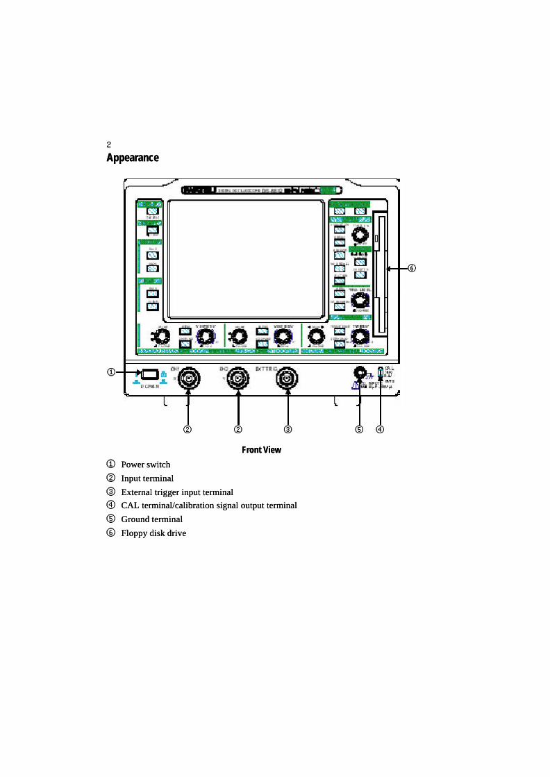
AppearanceAppearance
Front ViewFront View
①① Power switchPower switch
②② Input terminalInput terminal
③③ External trigger input terminalExternal trigger input terminal
④④ CAL terminal/calibration signal output terminalCAL terminal/calibration signal output terminal
⑤⑤ Ground terminalGround terminal
⑥⑥ Floppy disk driveFloppy disk drive
①①
②② ②② ③③ ④④⑤⑤
⑥⑥

33
Rear ViewRear View
①① Centronics portCentronics port
②② RS-232C portRS-232C port
③③ AC power inletAC power inlet
④④ Fuse holderFuse holder
⑤⑤ PCMCIA Type II slotPCMCIA Type II slot
Upper ViewUpper View
①① Built-in printerBuilt-in printer
①①
②② ⑤⑤
④④
③③
①①

44
KnobsKnobs
Single function knobSingle function knob: Turning or pressing the knob sets a range or level.: Turning or pressing the knob sets a range or level.CH1/CH2-VOLTS/DIV, CH1/CH2-OFFSET, TIME/DIV, DELAY, TRIG LEVELCH1/CH2-VOLTS/DIV, CH1/CH2-OFFSET, TIME/DIV, DELAY, TRIG LEVEL
FUNCTION knobFUNCTION knob: Selects and fixes an item on the menu screen and controls the V/H: Selects and fixes an item on the menu screen and controls the V/Hcursor position during cursor measurement.cursor position during cursor measurement.
Operation when knob is pressedOperation when knob is pressed
CH1/CH2-VOLTS/DIVCH1/CH2-VOLTS/DIV: Toggles the function 1-2-5 sequence or 1 to 2.5 times ZOOM: Toggles the function 1-2-5 sequence or 1 to 2.5 times ZOOMwhen the knob is rotated.when the knob is rotated.
CH1/CH2-OFFSETCH1/CH2-OFFSET : The trace shifts in 1-division steps in the direction the knob was: The trace shifts in 1-division steps in the direction the knob waslast turned.last turned.
TIME/DIVTIME/DIV: The sweep rate changes 10 times in the direction the knob was last turned.: The sweep rate changes 10 times in the direction the knob was last turned.
DELAY, TRIG LEVELDELAY, TRIG LEVEL: The setting value changes in 1-division steps in the direction the: The setting value changes in 1-division steps in the direction theknob was last turned.knob was last turned.
Operating buttons and knobsOperating buttons and knobs
Buttons Buttons
Single function buttonSingle function button: Pressing the button executes the associated function.: Pressing the button executes the associated function.
AUTOSET, RUN/STOP, HELP, COPY, SETUP SAVE, SETUP UNDO, REF SAVE,AUTOSET, RUN/STOP, HELP, COPY, SETUP SAVE, SETUP UNDO, REF SAVE,REF CLEAR, ZERO DELAYREF CLEAR, ZERO DELAY
Function selection buttonFunction selection button: Pressing the button changes the function.: Pressing the button changes the function.
CursorCursor:: ∆∆V/V/∆∆t/t/∆∆V&V&∆∆t/V at t/OFF, C1/C2/TCKt/V at t/OFF, C1/C2/TCKSweep modeSweep mode :: AUTO/NORM/SGLAUTO/NORM/SGLCouplingCoupling:: COUPLING, PERSISTENCECOUPLING, PERSISTENCE
Menu display buttonMenu display button: Pressing the : Pressing the MENU MENU button displays the menu screen. (For thebutton displays the menu screen. (For themenu hierarchy, see 0-14 to 19.) The color of the button is gray.menu hierarchy, see 0-14 to 19.) The color of the button is gray.
ACQUISITION, DISPLAY, MEASURE, SAVE/RECALL, UTILITIES, CH1, CH2, TRIGACQUISITION, DISPLAY, MEASURE, SAVE/RECALL, UTILITIES, CH1, CH2, TRIG

55
[Example][Example] Set “Scale” to “Grid” in the Display menu. Set “Scale” to “Grid” in the Display menu.
Selection method with FUNCTIONSelection method with FUNCTION
1.1. Press the DISPLAY button to show the display menu.Press the DISPLAY button to show the display menu.
2.2. Turn the FUNCTION knob to select Turn the FUNCTION knob to select ..3.3. Press the FUNCTION knob to fix the menu item.Press the FUNCTION knob to fix the menu item.The setting item is displayed in reverse video.The setting item is displayed in reverse video.4.4. Turn the FUNCTION knob to select Turn the FUNCTION knob to select ..5.5. Press the FUNCTION knob to fix the setting item.Press the FUNCTION knob to fix the setting item.The selected mThe selected meenu item is displayed in reverse video.nu item is displayed in reverse video.
Menu (FUNCTION) operationMenu (FUNCTION) operation
Selection method with MENU Selection method with MENU 1.1. Press the DISPLAY button to show the display menu.Press the DISPLAY button to show the display menu.2.2. Turn the FUNCTION knob to select Turn the FUNCTION knob to select ..
3.3. Pressing the DISPLAY button selects Frame, Grid or Axes.Pressing the DISPLAY button selects Frame, Grid or Axes.
Setting a numerical valueSetting a numerical value
There are two ways of selecting a setting item in the menu; one is to turn the FUNCTIONThere are two ways of selecting a setting item in the menu; one is to turn the FUNCTIONknob to select an item, and then press the knob to fix it, and the other is to fix the itemknob to select an item, and then press the knob to fix it, and the other is to fix the itemby pressing the menu button while the item is displayed.by pressing the menu button while the item is displayed.
Set the numerical value of Hold off in the trigger menu, Interval ofSet the numerical value of Hold off in the trigger menu, Interval ofEvent trigger or Line of TV as follows:Event trigger or Line of TV as follows:For the setting of File No. in SAVE/RECALL, Copy menu, see pagesFor the setting of File No. in SAVE/RECALL, Copy menu, see pages34 to 37.34 to 37.←← Pressing the FUNCTION knob changes the numerical value Pressing the FUNCTION knob changes the numerical valuedisplayed in reverse video one by one. Pressing the FUNCTION knobdisplayed in reverse video one by one. Pressing the FUNCTION knobagain after the numerical setting is done changes the settable menu toagain after the numerical setting is done changes the settable menu to“Coarse” after the values are confirmed.“Coarse” after the values are confirmed.←← Pressing the FUNCTION knob changes the numerical value in rough Pressing the FUNCTION knob changes the numerical value in roughsteps. The set value is displayed in reverse video. Pressing thesteps. The set value is displayed in reverse video. Pressing theFUNCTION knob again after the numerical setting is done changes theFUNCTION knob again after the numerical setting is done changes thesettable menu to “Hold off” after the values are confirmed.settable menu to “Hold off” after the values are confirmed.
From the following explanations, the operation of setting Scale in the DisplayFrom the following explanations, the operation of setting Scale in the Displaymenu to Grid (a series of operations 2 to 5 enclosed with dotted line above) ismenu to Grid (a series of operations 2 to 5 enclosed with dotted line above) isexpressed as follows:expressed as follows:Through [FUNCTION operation], set Scale menu to Grid.Through [FUNCTION operation], set Scale menu to Grid.
Bear in mind!!Bear in mind!!

66
[MENU] button[MENU] button : Displays the : Displays the ACQUISITION, DISPLAY,ACQUISITION, DISPLAY,MEASURE, SAVE/RECALLMEASURE, SAVE/RECALL and and UTILITIES UTILITIES menus.menus.
[FUNCTION] knob[FUNCTION] knob: Selects and fixes an item on the menu: Selects and fixes an item on the menuscreen and controls the V/H cursor position during cursorscreen and controls the V/H cursor position during cursormeasurement. (P5)measurement. (P5)
[[∆∆V, V, ∆∆t, t, ∆∆V/V/∆∆t, V at t, Off] buttont, V at t, Off] button: Selects the cursor measurement: Selects the cursor measurementitem from item from ∆∆V V →→ ∆∆t t →→ ∆∆V/V/∆∆t t →→ V at t V at t →→ Off. The selected Off. The selecteditem is displayed at the top of the screen. (P22)item is displayed at the top of the screen. (P22)
[C1/C2/TCK] button[C1/C2/TCK] button : Selects active cursors (C1, C2, or: Selects active cursors (C1, C2, ortracking) to be moved by the FUNCTION knob duringtracking) to be moved by the FUNCTION knob duringcursor measurement. (P22)cursor measurement. (P22)
Description of operation sectionDescription of operation sectionShown in ( ) is the reference page.Shown in ( ) is the reference page. [CH1/CH2 MENU] button[CH1/CH2 MENU] button:: Displays the CH-1Displays the CH-1
and CH-2 menus. (P14, P15, P42, 43)and CH-2 menus. (P14, P15, P42, 43)
[COUPLING] button[COUPLING] button:: Selects the input signalSelects the input signalcoupling from DC coupling from DC →→ Ground Ground →→ AC. (P15) AC. (P15)
[OFFSET] knob[OFFSET] knob:: Sets the vertical position of aSets the vertical position of atrace. (P14)trace. (P14)
[VOLTS/DIV] knob[VOLTS/DIV] knob: Continuously selects the deflection factor in 1-2-5 sequence or : Continuously selects the deflection factor in 1-2-5 sequence or ´1 to1 to´2.5 zoom as fine adjustment of the vertical deflection factor. Pressing the knob switches2.5 zoom as fine adjustment of the vertical deflection factor. Pressing the knob switchesbetween 1-2-5 sequence and zoom. (P14)between 1-2-5 sequence and zoom. (P14)
[TRIG MENU] button[TRIG MENU] button: Displays the TRIGGER menu. (P18): Displays the TRIGGER menu. (P18)
[TRIG LEVEL] knob[TRIG LEVEL] knob: Sets the trigger level. (P18): Sets the trigger level. (P18)
[AUTO/NORM/SGL] button[AUTO/NORM/SGL] button: Selects the sweep mode from Auto: Selects the sweep mode from Auto→→ Normal Normal →→ Single. (P20) Single. (P20)
77
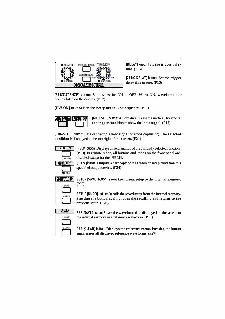
[HELP] button[HELP] button: Displays an explanation of the currently selected function.: Displays an explanation of the currently selected function.(P10). In remote mode, all buttons and knobs on the front panel are(P10). In remote mode, all buttons and knobs on the front panel aredisabled except for the [HELP].disabled except for the [HELP].
[DELAY] knob[DELAY] knob: Sets the trigger delay: Sets the trigger delaytime. (P16)time. (P16)
[ZERO DELAY] button[ZERO DELAY] button: Set the trigger: Set the triggerdelay time to zero. (P16)delay time to zero. (P16)
[AUTOSET] button[AUTOSET] button: Automatically sets the vertical, horizontal: Automatically sets the vertical, horizontaland trigger condition to show the input signal. (P12)and trigger condition to show the input signal. (P12)
[PERSISTENCE] button[PERSISTENCE] button : Sets overwrite ON or OFF. When ON, waveforms are: Sets overwrite ON or OFF. When ON, waveforms areaccumulated on the display. (P17)accumulated on the display. (P17)
[TIME/DIV] knob[TIME/DIV] knob: Selects the sweep rate in 1-2-5 sequence. (P16): Selects the sweep rate in 1-2-5 sequence. (P16)
[RUN/STOP] button[RUN/STOP] button: Sets capturing a new signal or stops capturing. The selected: Sets capturing a new signal or stops capturing. The selectedcondition is displayed at the top right of the screen. (P21)condition is displayed at the top right of the screen. (P21)
[COPY] button[COPY] button: Outputs a hardcopy of the screen or setup condition to a: Outputs a hardcopy of the screen or setup condition to aspecified output device. (P24)specified output device. (P24)
SETUP [SAVE] buttonSETUP [SAVE] button: Saves the current setup to the internal memory.: Saves the current setup to the internal memory.(P26)(P26)
SETUP [UNDO] buttonSETUP [UNDO] button: Recalls the saved setup from the internal memory.: Recalls the saved setup from the internal memory.Pressing the button again undoes the recalling and returns to thePressing the button again undoes the recalling and returns to theprevious setup. (P26)previous setup. (P26)
REF [SAVE] buttonREF [SAVE] button: Saves the waveform data displayed on the screen to: Saves the waveform data displayed on the screen tothe internal memory as a reference waveform. (P27)the internal memory as a reference waveform. (P27)
REF [CLEAR] buttonREF [CLEAR] button: Displays the reference menu. Pressing the button: Displays the reference menu. Pressing the buttonagain erases all displayed reference waveforms. (P27)again erases all displayed reference waveforms. (P27)
88
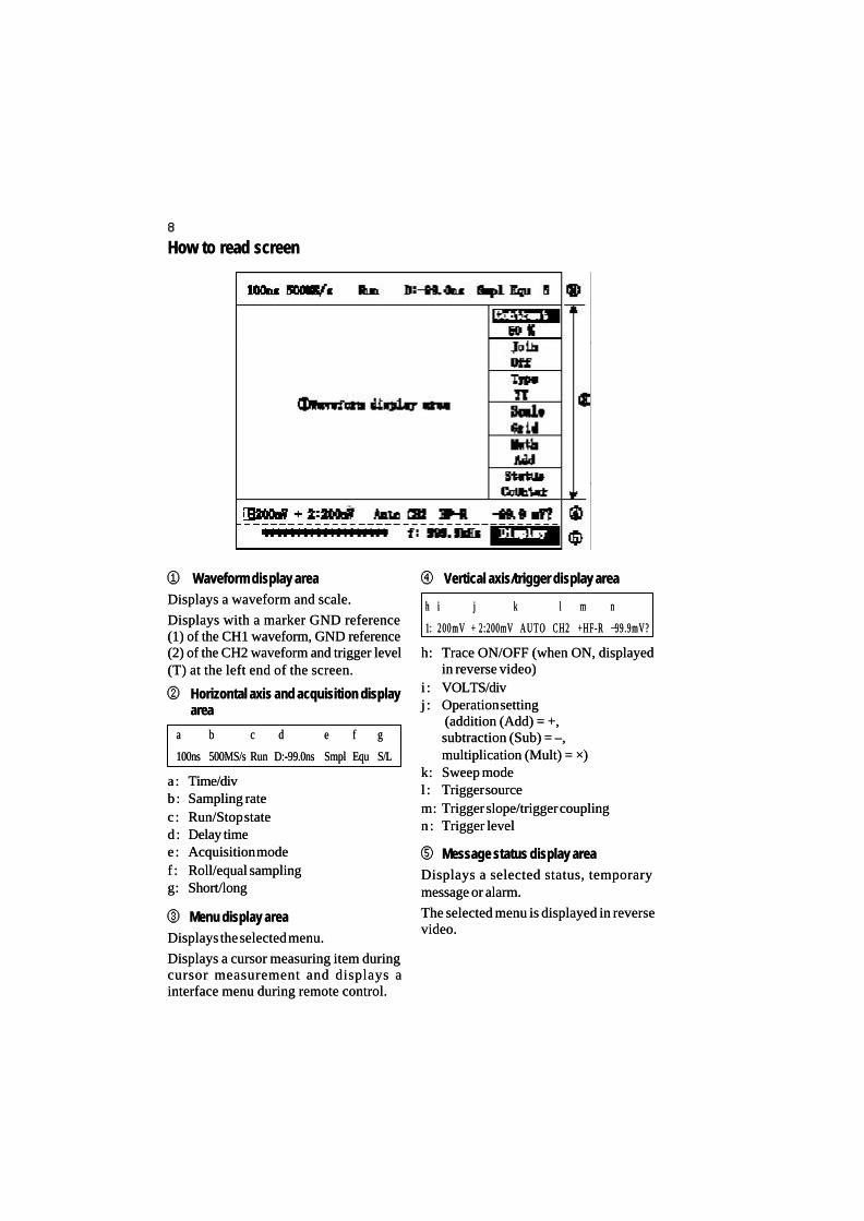
How to read screenHow to read screen
④④ Vertical axis/trigger display areaVertical axis/trigger display area
h:h: Trace ON/OFF (when ON, displayedTrace ON/OFF (when ON, displayedin reverse video)in reverse video)
i :i : VOLTS/divVOLTS/divj :j : Operation settingOperation setting
(addition (Add) = +, (addition (Add) = +,subtraction (Sub) = –,subtraction (Sub) = –,multiplication (Mult) = multiplication (Mult) = ××))
k:k: Sweep modeSweep model :l : Trigger sourceTrigger sourcem:m: Trigger slope/trigger couplingTrigger slope/trigger couplingn:n : Trigger levelTrigger level
⑤⑤ Message status display areaMessage status display areaDisplays a selected status, temporaryDisplays a selected status, temporarymessage or alarm.message or alarm.
The selected menu is displayed in reverseThe selected menu is displayed in reversevideo.video.
①① Waveform display areaWaveform display areaDisplays a waveform and scale.Displays a waveform and scale.
Displays with a marker GND referenceDisplays with a marker GND reference(1) of the CH1 waveform, GND reference(1) of the CH1 waveform, GND reference(2) of the CH2 waveform and trigger level(2) of the CH2 waveform and trigger level(T) at the left end of the screen.(T) at the left end of the screen.
②② Horizontal axis and acquisition displayHorizontal axis and acquisition displayareaarea
a:a: Time/divTime/divb:b : Sampling rateSampling ratec:c: Run/Stop stateRun/Stop stated :d : Delay timeDelay timee:e: Acquisition modeAcquisition modef :f : Roll/equal samplingRoll/equal samplingg:g: Short/longShort/long
③③ Menu display areaMenu display areaDisplays the selected menu.Displays the selected menu.
Displays a cursor measuring item duringDisplays a cursor measuring item duringcursor measurement and displays acursor measurement and displays ainterface menu during remote control.interface menu during remote control.
aa bb cc dd ee ff gg
100ns100ns 500MS/s500MS/s RunRun D:-99.0nsD:-99.0ns SmplSmpl EquEqu S/LS/L
hh ii j j kk ll mm nn
1:1: 200mV200mV ++ 2:200mV2:200mV A U T OA U T O CH2CH2 +HF-R+HF-R −−99.9mV?99.9mV?

99
GND: Reference mark displayGND: Reference mark displayIndicates the GND position withIndicates the GND position with‘_’. Up/down arrows ‘_’. Up/down arrows or or arearedisplayed at the upper or lowerdisplayed at the upper or lowerposition when the channel positionposition when the channel positionis outside of the display area.is outside of the display area.
Trigger level mark displayTrigger level mark displayIndicates the trigger position withIndicates the trigger position with‘T’ when the trigger coupling is DC‘T’ when the trigger coupling is DCor HF-REJ.or HF-REJ.
Up/down arrows Up/down arrows or or arearedisplayed at the upper or lowerdisplayed at the upper or lowerposition when the trigger delayposition when the trigger delayposition is outside the display area.position is outside the display area.
Delay mark displayDelay mark displayIndicates the trigger position withIndicates the trigger position with‘‘ ’.’.Right or left arrows Right or left arrows arearedisplayed when the trigger positiondisplayed when the trigger positionis outside the display area.is outside the display area.
←← Menu item: Displays the selection status in reverse video.Menu item: Displays the selection status in reverse video.←← Menu setting: Displays the current setting. If the setting is selectedMenu setting: Displays the current setting. If the setting is selected
in [FUNCTION operation], it is displayed in reverse video.in [FUNCTION operation], it is displayed in reverse video.
Understanding the menu structureUnderstanding the menu structure
Numerical value setting menuNumerical value setting menu
Press the FUNCTION Press the FUNCTION knob knob at this position to change the numericalat this position to change the numericalvalue one by one.value one by one.Press the FUNCTION Press the FUNCTION knob knob at this position to change the numericalat this position to change the numericalvalue in rough steps.value in rough steps.
←← Indicates that there are more items below.Indicates that there are more items below.
←← Shows the menu displayed in the menu display area.Shows the menu displayed in the menu display area.
Marks on waveform displayMarks on waveform display
CH1 GND reference markCH1 GND reference mark
Trigger level markTrigger level mark
CH2 GND reference markCH2 GND reference mark
Delay markDelay mark

1010
Setting of dateSetting of date
The date is used for time display but also for the time stamp when saving a file andThe date is used for time display but also for the time stamp when saving a file andcapturing a waveform.capturing a waveform.
1.1. Select Date in the UTILITIES menu with [FUNCTION operation].Select Date in the UTILITIES menu with [FUNCTION operation].
2.2. Press the FUNCTION knob to show the Date menu.Press the FUNCTION knob to show the Date menu.
3.3. Select Month from 1 to 12 with [FUNCTION operation].Select Month from 1 to 12 with [FUNCTION operation].
Set Date, Year, Hours and Minutes in the same way.Set Date, Year, Hours and Minutes in the same way.
The seconds are set to zero when fixing the date menu.The seconds are set to zero when fixing the date menu.
Before starting the measurementBefore starting the measurementMake the following adjustments if necessary.Make the following adjustments if necessary.
Contrast settingContrast setting
Adjusts the contrast of the screen.Adjusts the contrast of the screen.
The contrast is automatically set initially according to the ambient light when theThe contrast is automatically set initially according to the ambient light when thepower is turned on. You may adjust the contrast manually if necessary.power is turned on. You may adjust the contrast manually if necessary.
This manually-adjusted condition is maintained until the power is turned off.This manually-adjusted condition is maintained until the power is turned off.
1.1. Press the DISPLAY button to show the Display menu.Press the DISPLAY button to show the Display menu.
2.2. Adjust Contrast between 0 and 100% with [FUNCTION operation] to get theAdjust Contrast between 0 and 100% with [FUNCTION operation] to get theappropriate screen brightness.appropriate screen brightness.
Selection of languageSelection of language
Selects the HELP language.Selects the HELP language.
1.1. Select Config in the UTILITIES menu with [FUNCTION operation].Select Config in the UTILITIES menu with [FUNCTION operation].
2.2. Press the FUNCTION knob to show the Config menu.Press the FUNCTION knob to show the Config menu.
3.3. Select Language in the Language menu with [FUNCTION operation].Select Language in the Language menu with [FUNCTION operation].
Press the HELP button at the top left. An explanation of the last operated functionPress the HELP button at the top left. An explanation of the last operated functionis displayed.is displayed.
HELP is canceled by any operation.HELP is canceled by any operation.
HELP functionHELP function

1111
How to restore the setting at time of purchaseHow to restore the setting at time of purchase
1.1. Through [FUNCTION operation], set the SAVE/RECALL menu to DEFAULT.Through [FUNCTION operation], set the SAVE/RECALL menu to DEFAULT.
2.2. Pressing the FUNCTION knob shows a message "Push the FUNCTION to goPressing the FUNCTION knob shows a message "Push the FUNCTION to goon".on".
3.3. Pressing the FUNCTION knob again returns the panel setting (readout and partPressing the FUNCTION knob again returns the panel setting (readout and partof menu) to the factory setting.of menu) to the factory setting.Copy-related or interface-related settings, etc. are not changed (see Document 4).Copy-related or interface-related settings, etc. are not changed (see Document 4).
Reverse display function (LCD)Reverse display function (LCD)
Toggles the screen between Normal (white background) and Reverse (blueToggles the screen between Normal (white background) and Reverse (bluebackground).background).
This function affects only the LCD display and does not affect the copy output.This function affects only the LCD display and does not affect the copy output.
1.1. Select Config in the UTILITIES menu with [FUNCTION operation].Select Config in the UTILITIES menu with [FUNCTION operation].
2.2. Press the FUNCTION knob to display the Config menu.Press the FUNCTION knob to display the Config menu.
3.3. Set the LCD menu to Normal or Reverse with [FUNCTION operation].Set the LCD menu to Normal or Reverse with [FUNCTION operation].
Display date on the screenDisplay date on the screen
To display the date in the message area, select Date in the Status menu.To display the date in the message area, select Date in the Status menu.
1.1. Press the DISPLAY button.Press the DISPLAY button.
2.2. Select Date in the Status menu with [FUNCTION operation].Select Date in the Status menu with [FUNCTION operation].
3.3. The date is displayed at the bottom right of the screen.The date is displayed at the bottom right of the screen.
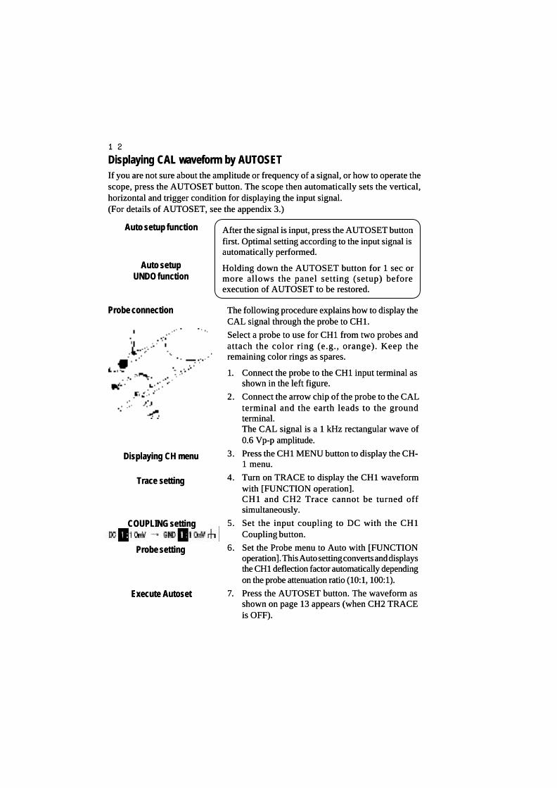
1212
The following procedure explains how to display theThe following procedure explains how to display theCAL signal through the probe to CH1.CAL signal through the probe to CH1.
Select a probe to use for CH1 from two probes andSelect a probe to use for CH1 from two probes andattach the color ring (e.g., orange). Keep theattach the color ring (e.g., orange). Keep theremaining color rings as spares.remaining color rings as spares.
1.1. Connect the probe to the CH1 input terminal asConnect the probe to the CH1 input terminal asshown in the left figure.shown in the left figure.
2.2. Connect the arrow chip of the probe to the CALConnect the arrow chip of the probe to the CALterminal and the earth leads to the groundterminal and the earth leads to the groundterminal.terminal.The CAL signal is a 1 kHz rectangular wave ofThe CAL signal is a 1 kHz rectangular wave of0.6 Vp-p amplitude.0.6 Vp-p amplitude.
3.3. Press the CH1 MENU button to display the CH-Press the CH1 MENU button to display the CH-1 menu.1 menu.
4.4. Turn on TRACE to display the CH1 waveformTurn on TRACE to display the CH1 waveformwith [FUNCTION operation].with [FUNCTION operation].CH1 and CH2 Trace cannot be turned offCH1 and CH2 Trace cannot be turned offsimultaneously.simultaneously.
5.5. Set the input coupling to DC with the CH1Set the input coupling to DC with the CH1Coupling button.Coupling button.
6.6. Set the Probe menu to Auto with [FUNCTIONSet the Probe menu to Auto with [FUNCTIONoperation]. This Auto setting converts and displaysoperation]. This Auto setting converts and displaysthe CH1 deflection factor automatically dependingthe CH1 deflection factor automatically dependingon the probe attenuation ratio (10:1, 100:1).on the probe attenuation ratio (10:1, 100:1).
7.7. Press the AUTOSET button. The waveform asPress the AUTOSET button. The waveform asshown on page 13 appears (when CH2 TRACEshown on page 13 appears (when CH2 TRACEis OFF).is OFF).
Displaying CAL waveform by AUTOSETDisplaying CAL waveform by AUTOSETIf you are not sure about the amplitude or frequency of a signal, or how to operate theIf you are not sure about the amplitude or frequency of a signal, or how to operate thescope, press the AUTOSET button. The scope then automatically sets the vertical,scope, press the AUTOSET button. The scope then automatically sets the vertical,horizontal and trigger condition for displaying the input signal.horizontal and trigger condition for displaying the input signal.(For details of AUTOSET, see the appendix 3.)(For details of AUTOSET, see the appendix 3.)
Probe connectionProbe connection
Displaying CH menuDisplaying CH menu
Trace settingTrace setting
Probe settingProbe setting
Execute AutosetExecute Autoset
COUPLING settingCOUPLING setting
Auto setup functionAuto setup function
Auto setupAuto setupUNDO functionUNDO function
After the signal is input, press the AUTOSET buttonAfter the signal is input, press the AUTOSET buttonfirst. Optimal setting according to the input signal isfirst. Optimal setting according to the input signal isautomatically performed.automatically performed.
Holding down the AUTOSET button for 1 sec orHolding down the AUTOSET button for 1 sec ormore allows the panel setting (setup) beforemore allows the panel setting (setup) beforeexecution of AUTOSET to be restored.execution of AUTOSET to be restored.

1313
Probe compensationProbe compensation
ProceduresProcedures
Adjust the variable capacitor of the probe by turning with a screwdriver to achieve aAdjust the variable capacitor of the probe by turning with a screwdriver to achieve aflat response on a square wave.flat response on a square wave.
The probe is used to provide a convenient, reliable and repeatable method ofThe probe is used to provide a convenient, reliable and repeatable method ofcoupling the DUT to the oscilloscope. The probe is used to minimizecoupling the DUT to the oscilloscope. The probe is used to minimizemeasurement error due to loading, poor shielding and limited frequencymeasurement error due to loading, poor shielding and limited frequencybandwidth.bandwidth.Consider the problems that arise when a wire is connected directly from a DUTConsider the problems that arise when a wire is connected directly from a DUTto the input terminal of an oscilloscope:to the input terminal of an oscilloscope:1)1) Susceptible to interference and noiseSusceptible to interference and noise2)2) Limited frequency bandwidthLimited frequency bandwidth3)3) Large loading effect on DUTLarge loading effect on DUTThe first problem can be remedied by using a coaxial cable or shielded wire.The first problem can be remedied by using a coaxial cable or shielded wire.However, this does not resolve the second and third problems.However, this does not resolve the second and third problems.The second problem of limited frequency bandwidth is caused by the inductanceThe second problem of limited frequency bandwidth is caused by the inductanceand stray capacitance of the wire. Use of a 10:1 probe will eliminate such anand stray capacitance of the wire. Use of a 10:1 probe will eliminate such aneffect.effect.The third problem, the large loading effect, is due to poor impedance matchingThe third problem, the large loading effect, is due to poor impedance matchingbetween the DUT and oscilloscope. This can be minimized by using anbetween the DUT and oscilloscope. This can be minimized by using anappropriate probe.appropriate probe.
10:1 PURPOSE OF THE PROBE10:1 PURPOSE OF THE PROBE
Correctly compensatedCorrectly compensatedwaveformwaveform
ExcessiveExcessivecompensationcompensation
Adjust it so that thisAdjust it so that thispart may be flat.part may be flat.
InsufficientInsufficientcompensationcompensation
Before using a probe, it is necessary to perform a probe compensation adjustment.Before using a probe, it is necessary to perform a probe compensation adjustment.Probe compensation adjusts the frequency characteristic of the probe to match theProbe compensation adjusts the frequency characteristic of the probe to match theoscilloscope input. If a probe is used without such probe compensation adjustment,oscilloscope input. If a probe is used without such probe compensation adjustment,the measured signal may contain a significant error.the measured signal may contain a significant error.

1414
Operating vertical axisOperating vertical axis
Sets the position of the waveform in the vertical direction.Sets the position of the waveform in the vertical direction.Pressing OFFSET moves the waveform inPressing OFFSET moves the waveform in1-division steps in the direction it was last1-division steps in the direction it was lastmoved. The offset variable range is as follows:moved. The offset variable range is as follows:2 mV to 50 mV/DIV:2 mV to 50 mV/DIV: ±1 V±1 V100 mV to 500 mV/DIV:100 mV to 500 mV/DIV: ±10 V±10 V1 V to 10 V/DIV:1 V to 10 V/DIV: ±100 V±100 V
OFFSETOFFSET
VOLTS/DIVVOLTS/DIV
ZoomZoom
DivisionDivision Enlarges or reduces the waveform based on the GND reference markEnlarges or reduces the waveform based on the GND reference mark(GND position).(GND position).
Pressing the VOLTS/DIV knob allows the vertical deflection factor toPressing the VOLTS/DIV knob allows the vertical deflection factor tobe alternately switched between 1-2-5 sequence and Zoom. (The samebe alternately switched between 1-2-5 sequence and Zoom. (The samefunction is available using the CH menu.)function is available using the CH menu.)If “Zoom” is selected, the setting varies continuously from 1.00 to 2.50If “Zoom” is selected, the setting varies continuously from 1.00 to 2.50(maximum 0.8 mV/div). (Expansion by software)(maximum 0.8 mV/div). (Expansion by software)The waveform is enlarged based on the screen center regardless of theThe waveform is enlarged based on the screen center regardless of theoffset setting.offset setting.
VoltsVolts
Selects the deflection factor in 1-2-5 sequence.Selects the deflection factor in 1-2-5 sequence.This function varies depending on the offset setting in the CH menu.This function varies depending on the offset setting in the CH menu.
Enlarges or reduces the waveform based on the screen center.Enlarges or reduces the waveform based on the screen center.Set the waveform to the screen center with the OFFSET knob. UsefulSet the waveform to the screen center with the OFFSET knob. Usefulfor observing the exact part of the waveform you are interested in.for observing the exact part of the waveform you are interested in.
CH1/CH2 MENUCH1/CH2 MENU
TraceTrace
Displays CH1 and/or CH2 MENU.Displays CH1 and/or CH2 MENU.
Selects display(On) or non-display(Off) of CH1/CH2 waveform.Selects display(On) or non-display(Off) of CH1/CH2 waveform.

1515
Selects the input signal coupling from DC Selects the input signal coupling from DC →→ Ground Ground →→ AC. AC.COUPLINGCOUPLING
BWBW
CautionCaution Do not apply a voltage exceeding the specified voltage to the inputDo not apply a voltage exceeding the specified voltage to the inputterminal.terminal.Direct connection:Direct connection: ±400 V (DC+AC peak)±400 V (DC+AC peak)When SS-0130R or equivalent probe is used:When SS-0130R or equivalent probe is used: ±600 V (DC+AC peak)±600 V (DC+AC peak)[Note][Note] The maximum input voltage is de-rated at a frequency of 1The maximum input voltage is de-rated at a frequency of 1
MHz or higher.MHz or higher.
AC coupling (V) AC coupling (V) : The signal is connected via a capacitor and the signal: The signal is connected via a capacitor and the signalof 10 Hz or below is attenuated and the DC component is blocked.of 10 Hz or below is attenuated and the DC component is blocked.
This coupling is used to observe the signal while canceling the DCThis coupling is used to observe the signal while canceling the DClevel.level.
DC coupling (V) DC coupling (V) : All signal frequency components including the DC: All signal frequency components including the DCcomponent are passed.component are passed.
GND ( ) GND ( ) : Displays the ground level (0 V).: Displays the ground level (0 V).
BW ON/OFFBW ON/OFF: The AC component of 10 MHz or higher is attenuated: The AC component of 10 MHz or higher is attenuatedwhen ON is selected.when ON is selected.
BW is used to reduce noise of 10 MHz or higher in the signal.BW is used to reduce noise of 10 MHz or higher in the signal.
The same function is available using the CH menu.The same function is available using the CH menu.
Square wave whenSquare wave whenAC is selectedAC is selected
Square wave whenSquare wave whenDC is selectedDC is selected
~~
If ripple or noise occurs in the power output, it is better to use Volts than ACIf ripple or noise occurs in the power output, it is better to use Volts than AC
coupling.coupling.
How to use VoltsHow to use Volts

1616
Operating the horizontal axisOperating the horizontal axis
TIME/DIVTIME/DIV
DELAYDELAY Sets the position of the trigger point in the horizontal direction.Sets the position of the trigger point in the horizontal direction.
The Delay time shows from the trigger point to the screen center as theThe Delay time shows from the trigger point to the screen center as thezero point.zero point.
Note that the setting range of the delay time varies depending on theNote that the setting range of the delay time varies depending on thesweep rate and memory length setting. (See Section 2.)sweep rate and memory length setting. (See Section 2.)
ZERO DELAYZERO DELAY Sets the trigger delay time to zero.Sets the trigger delay time to zero.
The trigger point comes to the screen center when zero.The trigger point comes to the screen center when zero.
Select the sweep rate per scale (approximately 9 mm). The setting rangeSelect the sweep rate per scale (approximately 9 mm). The setting rangeis 5 ns to 50 s/div in 1-2-5 sequence. The waveform is expanded oris 5 ns to 50 s/div in 1-2-5 sequence. The waveform is expanded orreduced based on the screen center. (See the figure below.) reduced based on the screen center. (See the figure below.) The operationThe operationvaries depending on the delay setting.varies depending on the delay setting.
POST TRIGGERPOST TRIGGER PRE TRIGGERPRE TRIGGER
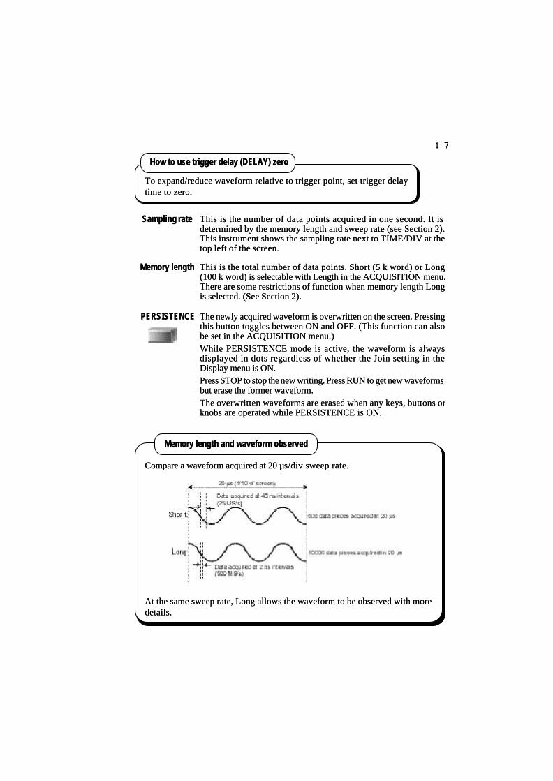
1717
Sampling rateSampling rate This is the number of data points acquired in one second. It isThis is the number of data points acquired in one second. It isdetermined by the memory length and sweep rate (see Section 2).determined by the memory length and sweep rate (see Section 2).This instrument shows the sampling rate next to TIME/DIV at theThis instrument shows the sampling rate next to TIME/DIV at thetop left of the screen.top left of the screen.
To expand/reduce waveform relative to trigger point, set trigger delayTo expand/reduce waveform relative to trigger point, set trigger delaytime to zero.time to zero.
How to use trigger delay (DELAY) zeroHow to use trigger delay (DELAY) zero
Memory length and waveform observedMemory length and waveform observed
Compare a waveform acquired at 20 Compare a waveform acquired at 20 µµs/div sweep rate.s/div sweep rate.
At the same sweep rate, Long allows the waveform to be observed with moreAt the same sweep rate, Long allows the waveform to be observed with moredetails.details.
Memory lengthMemory length This is the total number of data points. Short (5 k word) or LongThis is the total number of data points. Short (5 k word) or Long(100 k word) is selectable with Length in the ACQUISITION menu.(100 k word) is selectable with Length in the ACQUISITION menu.There are some restrictions of function when memory length LongThere are some restrictions of function when memory length Longis selected. (See Section 2).is selected. (See Section 2).
PERSISTENCEPERSISTENCE The newly acquired waveform is overwritten on the screen. PressingThe newly acquired waveform is overwritten on the screen. Pressingthis button toggles between ON and OFF. (This function can alsothis button toggles between ON and OFF. (This function can alsobe set in the ACQUISITION menu.)be set in the ACQUISITION menu.)While PERSISTENCE mode is active, the waveform is alwaysWhile PERSISTENCE mode is active, the waveform is alwaysdisplayed in dots regardless of whether the Join setting in thedisplayed in dots regardless of whether the Join setting in theDisplay menu is ON.Display menu is ON.Press STOP to stop the new writing. Press RUN to get new waveformsPress STOP to stop the new writing. Press RUN to get new waveformsbut erase the former waveform.but erase the former waveform.The overwritten waveforms are erased when any keys, buttons orThe overwritten waveforms are erased when any keys, buttons orknobs are operated while PERSISTENCE is ON.knobs are operated while PERSISTENCE is ON.

1818
TriggerTrigger
LevelLevel
Sets the trigger level voltage to generate a trigger signal.Sets the trigger level voltage to generate a trigger signal.
The trigger level setting range is ±5 div from the screen center.The trigger level setting range is ±5 div from the screen center.
A T mark is shown at the left end of the screen when the trigger couplingA T mark is shown at the left end of the screen when the trigger couplingis DC or HF-REJ.is DC or HF-REJ.
A “?” mark is displayed following the trigger level voltage display whenA “?” mark is displayed following the trigger level voltage display whenthe trigger coupling is AC or LF-REJ or the vertical coupling of the triggerthe trigger coupling is AC or LF-REJ or the vertical coupling of the triggersource channel is set to AC.source channel is set to AC.
The T mark position does not change when the voltage deflection factorThe T mark position does not change when the voltage deflection factor(VOLTS/DIV) is varied but the trigger level value is varied.(VOLTS/DIV) is varied but the trigger level value is varied.
Press the trigger level knob to set the trigger level in rough steps.Press the trigger level knob to set the trigger level in rough steps.
A trigger signal is generated at the cross point of the input signal and theA trigger signal is generated at the cross point of the input signal and thetrigger level.trigger level.
The relation between the trigger level, delay time and captured waveformThe relation between the trigger level, delay time and captured waveformis shown in the figure below.is shown in the figure below.
Trigger signalTrigger signal: : Sets the trigger level within the range of the signal amplitude to trigger.Sets the trigger level within the range of the signal amplitude to trigger.

1919
Trig TypeTrig Type
SlopeSlope
SourceSource
CouplingCoupling
Hold offHold off
Selects “Edge”, “EVENT” or “TV” Type in the TRIG menu.Selects “Edge”, “EVENT” or “TV” Type in the TRIG menu.(For EVENT and TV, see Section 2.)(For EVENT and TV, see Section 2.)The trigger signal is generated at the cross point of the input signalThe trigger signal is generated at the cross point of the input signaland the trigger level in the edge trigger as shown in the figure on pageand the trigger level in the edge trigger as shown in the figure on page19.19.
Use of EVENT trigger allows waveform to be acquired when a specific patternUse of EVENT trigger allows waveform to be acquired when a specific patternis established by specifying trigger generation count and synchronization.is established by specifying trigger generation count and synchronization.
Use of TV trigger allows stable observation of TV signal.Use of TV trigger allows stable observation of TV signal.
Selects the rising slope (Pos) or the falling slope (Neg) of the inputSelects the rising slope (Pos) or the falling slope (Neg) of the inputsignal to generate a trigger signal.signal to generate a trigger signal.
Selects the trigger signal source from CH1, CH2, EXT or LINE.Selects the trigger signal source from CH1, CH2, EXT or LINE.LINE generates a trigger signal the same as the power line frequency.LINE generates a trigger signal the same as the power line frequency.It is used for observing a signal synchronizing with the power supplyIt is used for observing a signal synchronizing with the power supplyfrequency.frequency.
Selects coupling of a trigger signal.Selects coupling of a trigger signal.AC coupling is useful for observing a signal on a DC voltage.AC coupling is useful for observing a signal on a DC voltage.HF-REJ rejects high frequency signal components such as noise toHF-REJ rejects high frequency signal components such as noise toensure stable triggering.ensure stable triggering.
ACAC Blocks the DC component of a trigger signal.Blocks the DC component of a trigger signal.DCDC Passes all frequency components of a trigger signal.Passes all frequency components of a trigger signal.HF-REJHF-REJ Low pass filter coupling. Rejects the frequencyLow pass filter coupling. Rejects the frequency
components above 10 kHz.components above 10 kHz.LF-REJLF-REJ High pass filter coupling. Rejects the frequencyHigh pass filter coupling. Rejects the frequency
components below 10 kHz.components below 10 kHz.
Specifies the trigger ignoring the period from the former trigger time.Specifies the trigger ignoring the period from the former trigger time.Setting range: 200 ns to 2 s and OFFSetting range: 200 ns to 2 s and OFF
EVENT trigger and TV triggerEVENT trigger and TV trigger
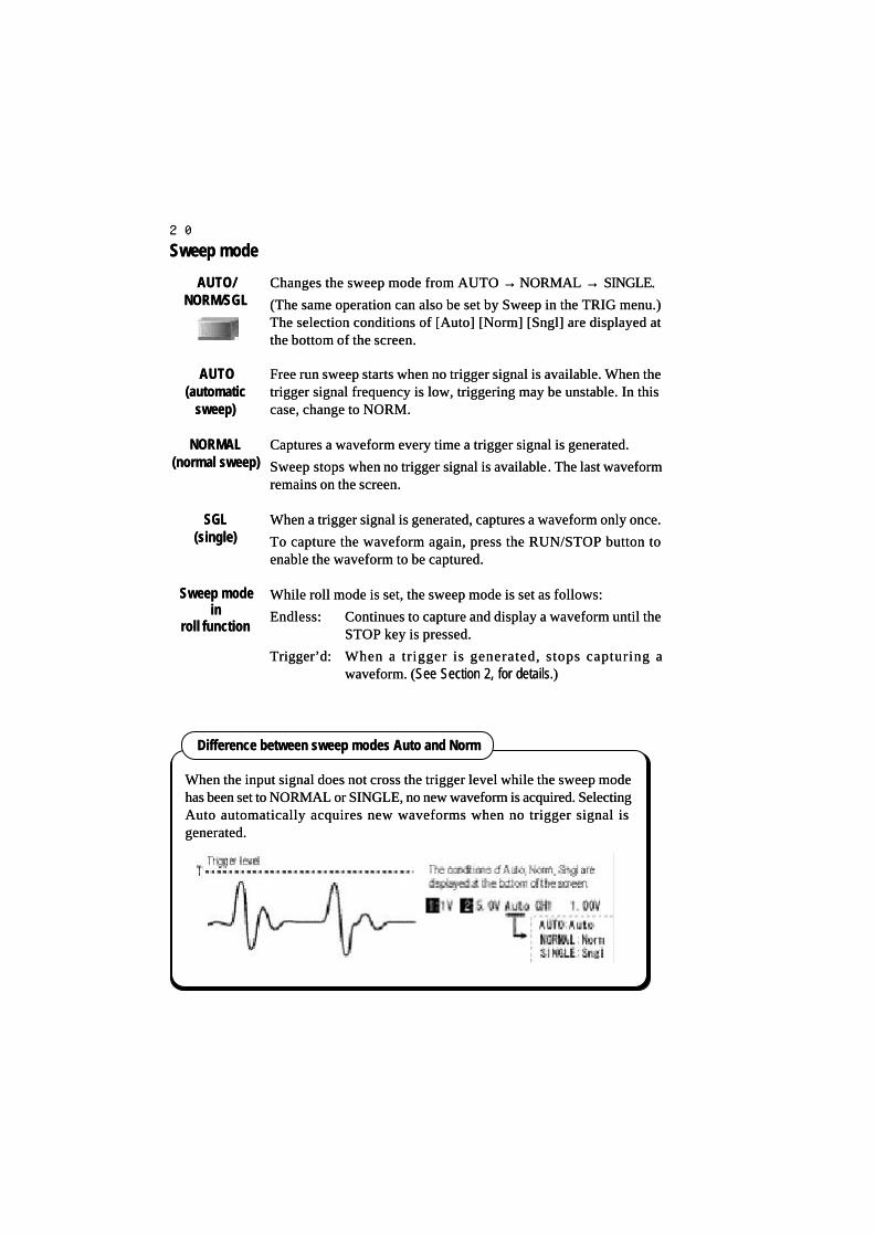
2020
Changes the sweep mode from AUTO Changes the sweep mode from AUTO →→ NORMAL NORMAL →→ SINGLE. SINGLE.
(The same operation can also be set by Sweep in the TRIG menu.)(The same operation can also be set by Sweep in the TRIG menu.)The selection conditions of [Auto] [Norm] [Sngl] are displayed atThe selection conditions of [Auto] [Norm] [Sngl] are displayed atthe bottom of the screen.the bottom of the screen.
Sweep modeSweep mode
AUTOAUTO(automatic(automatic
sweep)sweep)
NORMALNORMAL(normal sweep)(normal sweep)
SGLSGL(single)(single)
When the input signal does not cross the trigger level while the sweep modeWhen the input signal does not cross the trigger level while the sweep modehas been set to NORMAL or SINGLE, no new waveform is acquired. Selectinghas been set to NORMAL or SINGLE, no new waveform is acquired. SelectingAuto automatically acquires new waveforms when no trigger signal isAuto automatically acquires new waveforms when no trigger signal isgenerated.generated.
Difference between sweep modes Auto and NormDifference between sweep modes Auto and Norm
Sweep modeSweep modeinin
roll functionroll function
Free run sweep starts when no trigger signal is available. When theFree run sweep starts when no trigger signal is available. When thetrigger signal frequency is low, triggering may be unstable. In thistrigger signal frequency is low, triggering may be unstable. In thiscase, change to NORM.case, change to NORM.
Captures a waveform every time a trigger signal is generated.Captures a waveform every time a trigger signal is generated.
Sweep stops when Sweep stops when no trigger signal is availableno trigger signal is available. The last waveform. The last waveformremains on the screen.remains on the screen.
When a trigger signal is generated, captures a waveform only once.When a trigger signal is generated, captures a waveform only once.
To capture the waveform again, press the RUN/STOP button toTo capture the waveform again, press the RUN/STOP button toenable the waveform to be captured.enable the waveform to be captured.
While roll mode is set, the sweep mode is set as follows:While roll mode is set, the sweep mode is set as follows:
Endless:Endless: Continues to capture and display a waveform until theContinues to capture and display a waveform until theSTOP key is pressed.STOP key is pressed.
Trigger’d:Trigger’d: When a trigger is generated, stops capturing aWhen a trigger is generated, stops capturing awaveform. (waveform. (See Section 2, for details.See Section 2, for details.))
AUTO/AUTO/NORM/SGLNORM/SGL

2121
RUN/STOPRUN/STOP Sets start/stop of waveform capturing.Sets start/stop of waveform capturing.
Toggles between Run/Stop and displays the current condition at theToggles between Run/Stop and displays the current condition at thetop center of the screen.top center of the screen.
VOLTS/DIVVOLTS/DIV
TIME/DIVTIME/DIV
DELAYDELAY
Can be set to any range.Can be set to any range.
OperationOperationwhile STOPwhile STOP
OFFSETOFFSET
RUNRUN Starts the waveform capturing. Pressing RUN again while Run modeStarts the waveform capturing. Pressing RUN again while Run modestops the waveform capturing and captures a new waveform understops the waveform capturing and captures a new waveform undernew conditions.new conditions.
Stops capturing a new waveform in the STOP condition. The alreadyStops capturing a new waveform in the STOP condition. The alreadycaptured waveform (currently displayed waveform) can be enlargedcaptured waveform (currently displayed waveform) can be enlargedor reduced or its position can be varied for both the vertical andor reduced or its position can be varied for both the vertical andhorizontal axes.horizontal axes.
Can be set to any range.Can be set to any range.
Can be set to any range. However, there are some limitations ofCan be set to any range. However, there are some limitations of the theexpansion setting as follows.expansion setting as follows.
When memory length is Short: Max. 7 ranges expansionWhen memory length is Short: Max. 7 ranges expansion
When memory length is Long: Max. 11 ranges expansionWhen memory length is Long: Max. 11 ranges expansion
The reduction setting is limited to a maximum of 7 ranges irrespectiveThe reduction setting is limited to a maximum of 7 ranges irrespectiveof memory length.of memory length.
It is limited up to the screen center at both the top and tail of theIt is limited up to the screen center at both the top and tail of thewaveform.waveform.

2222
Cursor measurementCursor measurement
∆∆V/V/∆∆ t/t/∆∆V &V &∆∆ t/t/∆∆V at t/V at t/
OFFOFF
C1/C2/TCKC1/C2/TCK
FUNCTIONFUNCTION
When another menu is operatedWhen another menu is operated
∆∆V & V & ∆∆ttmeasurementmeasurement
It is possible to measure the voltage and time difference between twoIt is possible to measure the voltage and time difference between twocursors.cursors.
Horizontal (H cursor) and vertical (V cursor) are displayedHorizontal (H cursor) and vertical (V cursor) are displayedsimultaneously.simultaneously.
Cycles among the types of cursor measurement. The menu displayCycles among the types of cursor measurement. The menu displayarea shows the cursor measurement item and result.area shows the cursor measurement item and result.
Operating another menu erases the cursor measurement display.Operating another menu erases the cursor measurement display.To show it again, press the cursor button again.To show it again, press the cursor button again.
The cursor can be moved with the FUNCTION knob when cursorThe cursor can be moved with the FUNCTION knob when cursormeasurement is selected. (Normal menu operation is not possiblemeasurement is selected. (Normal menu operation is not possibleduring cursorduring cursor measurement.)measurement.)
Pressing the button of another menu returns to normal menu operations.Pressing the button of another menu returns to normal menu operations.
Pressing the FUNCTION knob moves the cursor in 1-division stepsPressing the FUNCTION knob moves the cursor in 1-division stepsin the direction the knob was last turned.in the direction the knob was last turned.
Selects the activeSelects the active cursor, either cursor 1 (C1) or cursor 2 (C2). cursor, either cursor 1 (C1) or cursor 2 (C2).
When TCK (Tracking) is selected, C1 and C2 can moveWhen TCK (Tracking) is selected, C1 and C2 can movesimultaneously.simultaneously.
The The activeactive cursor is displayed in the Select menu. cursor is displayed in the Select menu.
(In the following example, H-C2 is selected.)(In the following example, H-C2 is selected.)
IIt is selectable fromt is selectable from V-C1, V-C2, V-TRACK, H-C1, H-C2 and H-V-C1, V-C2, V-TRACK, H-C1, H-C2 and H-TRACK in TRACK in ∆∆V&V&∆∆tt measurement.measurement.
Operating cursorsOperating cursors
1.1. Pressing the Pressing the ∆∆V/V/∆∆t/t/∆∆V&V&∆∆t/t/∆∆Vat t/OFF button displays the CursorsVat t/OFF button displays the Cursorsmenu. Every depressing of the button changes Type (measurementmenu. Every depressing of the button changes Type (measurementtype) from type) from ∆∆VV→∆→∆ tt→∆→∆V&V&∆∆tt→∆→∆V at tV at t→→OFF. Here, OFF. Here, ∆∆V/V/∆∆t is set.t is set.
2.2. Every depressing of the C1/C2/TCK button switches SelectEvery depressing of the C1/C2/TCK button switches Select(operable cursor) from V-C1(operable cursor) from V-C1→→V-C2V-C2→→V-TRACKV-TRACK→→H-C1H-C1→→H-H-C2C2→→H-TRACK. Here, V-C1 is set.H-TRACK. Here, V-C1 is set.
3.3. Turn the FUNCTION knob to set the V-C1 cursor.Turn the FUNCTION knob to set the V-C1 cursor.
Repeat the operation in 2-3 to set V-C2, H-C1 and H-C2 likewise.Repeat the operation in 2-3 to set V-C2, H-C1 and H-C2 likewise.
4.4. Display the measured value of Display the measured value of ∆∆V/V/∆∆t in the menu.t in the menu.

2323
[Example] [Example] ∆∆V&V&∆∆ t measurementt measurement
V-C1V-C1
V-C2V-C2
H-C1H-C1 H-C2H-C2ΔΔ tt
ΔΔVV
→→ Measurement item currently selectedMeasurement item currently selected
→→ Cursor that can be operated by FUNCTIONCursor that can be operated by FUNCTIONknobknob
→→ ∆∆V measurement result at CH1 voltage sensitivityV measurement result at CH1 voltage sensitivity(When trace is OFF, *** is displayed)(When trace is OFF, *** is displayed)
→→ ∆∆V measurement result at CH2 voltage sensitivityV measurement result at CH2 voltage sensitivity
→→ Period Period ∆∆t measurementt measurement
→→ 1/1/∆∆t measurementt measurement
V at t measurementV at t measurement
Use of V at t allows measurement ofUse of V at t allows measurement ofthe voltage at the point at whichthe voltage at the point at whichwaveform crosses the H cursor andwaveform crosses the H cursor andthe time until the trigger point.the time until the trigger point.
Type of cursor measurementType of cursor measurement
Measurement typeMeasurement type DescriptionDescription Usable cursorUsable cursor
∆∆VV Voltage difference between V cursorsVoltage difference between V cursors V-C1, V-C2V-C1, V-C2∆∆t, 1/t, 1/∆∆tt Time difference between H cursors and 1/Time difference between H cursors and 1/∆∆tt H-C1, H-C2H-C1, H-C2∆∆V&V&∆∆tt Voltage difference between V cursorsVoltage difference between V cursors V-C1, V-C2V-C1, V-C2
Time difference between H cursors and 1/Time difference between H cursors and 1/∆∆tt H-C1, H-C2H-C1, H-C2V at tV at t Voltage at point that crosses H cursorVoltage at point that crosses H cursor H-C1H-C1
Time difference between trigger point to H cursorTime difference between trigger point to H cursor
Use of the MEASURE function allows automatic measurement of the amplitudeUse of the MEASURE function allows automatic measurement of the amplitudeof waveform, period and other 13 measurement items. (See Section 2.)of waveform, period and other 13 measurement items. (See Section 2.)
The H cursors are also used to specify the measurement area of automaticThe H cursors are also used to specify the measurement area of automaticmeasurement.measurement.
Using H cursors for other than cursor measurementUsing H cursors for other than cursor measurement

2424
Copy functionCopy function
CopyCopy
UTILITIESUTILITIES
Copy MenuCopy Menu
Outputs a hard copy of the screen to the built-in printer, floppy disk,Outputs a hard copy of the screen to the built-in printer, floppy disk,ATA card and Centronics port.ATA card and Centronics port.
Outputs a hard copy of the screen to a specified device.Outputs a hard copy of the screen to a specified device.
See Section 2, for details.See Section 2, for details.
Displays the UTILITIES menu. Select Copy in the UTILITIES menuDisplays the UTILITIES menu. Select Copy in the UTILITIES menuwith [FUNCTION operation].with [FUNCTION operation].
Select an output device, format and source. (See Section 2 for details.) Select an output device, format and source. (See Section 2 for details.)
Making a hard copyMaking a hard copy
1.1. Display the Copy menu in the UTILITIES menu.Display the Copy menu in the UTILITIES menu.
2.2. Through [FUNCTION operation], set the Device menu to Printer.Through [FUNCTION operation], set the Device menu to Printer.
3.3. Through [FUNCTION operation], set the Autocopy menu to OFF.Through [FUNCTION operation], set the Autocopy menu to OFF.
4.4. Through [FUNCTION operation], set the Source menu to Screen.Through [FUNCTION operation], set the Source menu to Screen.
5.5. Every depressing of the Copy button outputs a hard copy of theEvery depressing of the Copy button outputs a hard copy of thescreen to the built-in printer.screen to the built-in printer.
Copy to floppy/ATA cardCopy to floppy/ATA card
•• If the output device is set to a floppy disk or ATA card, every depressing of theIf the output device is set to a floppy disk or ATA card, every depressing of theCopy button allows a hard copy of the screen to be saved in TIFF or BMPCopy button allows a hard copy of the screen to be saved in TIFF or BMPformat. See Section 2 for details.format. See Section 2 for details.
•• When Auto Copy is selected, every acquisition of waveform allows a hardWhen Auto Copy is selected, every acquisition of waveform allows a hardcopy of the screen to be output to a specified device. See Section 2 for details.copy of the screen to be output to a specified device. See Section 2 for details.
Auto CopyAuto Copy
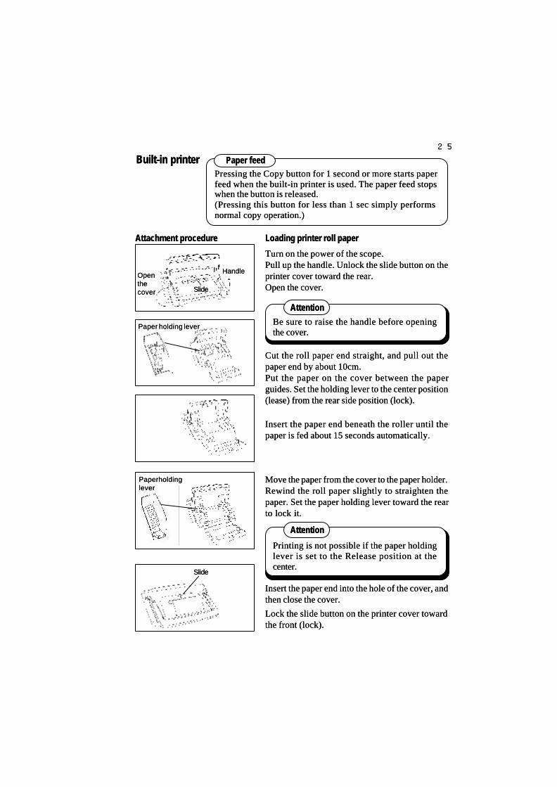
2525
Attachment procedureAttachment procedure
Built-in printerBuilt-in printerPressing the Copy button for 1 second or more starts paperPressing the Copy button for 1 second or more starts paperfeed when the built-in printer is used. The paper feed stopsfeed when the built-in printer is used. The paper feed stopswhen the button is released.when the button is released.(Pressing this button for less than 1 sec simply performs(Pressing this button for less than 1 sec simply performsnormal copy operation.)normal copy operation.)
Paper feedPaper feed
Paper holding leverPaper holding lever
SlideSlide
HandleHandleOpenOpenthethecovercover
Paper holdingPaper holdingleverlever
SlideSlide
Cut the roll paper end straight, and pull out theCut the roll paper end straight, and pull out thepaper end by about 10cm.paper end by about 10cm.Put the paper on the cover between the paperPut the paper on the cover between the paperguides. Set the holding lever to the center positionguides. Set the holding lever to the center position(lease) from the rear side position (lock).(lease) from the rear side position (lock).
Insert the paper end beneath the roller until theInsert the paper end beneath the roller until thepaper is fed about 15 seconds automatically.paper is fed about 15 seconds automatically.
Loading printer roll paperLoading printer roll paper
Turn on the power of the scope.Turn on the power of the scope.Pull up the handle. Unlock the slide button on thePull up the handle. Unlock the slide button on theprinter cover toward the rear.printer cover toward the rear.Open the cover.Open the cover.
Move the paper from the cover to the paper holder.Move the paper from the cover to the paper holder.Rewind the roll paper slightly to straighten theRewind the roll paper slightly to straighten thepaper. Set the paper holding lever toward the rearpaper. Set the paper holding lever toward the rearto lock it.to lock it.
Be sure to raise the handle before openingBe sure to raise the handle before openingthe cover.the cover.
AttentionAttention
AttentionAttention
Printing is not possible if the paper holdingPrinting is not possible if the paper holdinglever is set to the Release position at thelever is set to the Release position at thecenter.center.
Insert the paper end into the hole of the cover, andInsert the paper end into the hole of the cover, andthen close the cover.then close the cover.
Lock the slide button on the printer cover towardLock the slide button on the printer cover towardthe front (lock).the front (lock).

2626
SAVE/UNDO of SETUPSAVE/UNDO of SETUP
SSaves the current panel setting in internal memory. aves the current panel setting in internal memory. The internal memoryThe internal memorystores the condition immediately before the last pressing of the button.stores the condition immediately before the last pressing of the button.
Recalls the saved setup from the internal memory. Pressing this buttonRecalls the saved setup from the internal memory. Pressing this buttonagain undoes the recalling and returns to the previous setup.again undoes the recalling and returns to the previous setup.
[Example][Example] When two settings of measurement are switched alternately, oneWhen two settings of measurement are switched alternately, oneat a sweep rate of 1 ms and the other at a sweet rate of 0.1 ms.at a sweep rate of 1 ms and the other at a sweet rate of 0.1 ms.
1.1. After measurement is performed at a sweep rate of 1 ms/div, press theAfter measurement is performed at a sweep rate of 1 ms/div, press theSAVE button.SAVE button.
2.2. Set a sweep rate of 0.1 ms/div and carry out measurement.Set a sweep rate of 0.1 ms/div and carry out measurement.
3.3. Pressing the UNDO button recalls the panel setting at a sweep rate of 1Pressing the UNDO button recalls the panel setting at a sweep rate of 1ms/div.ms/div.
4.4. Pressing the UNDO button again recalls the 0.1 ms/div panel setting.Pressing the UNDO button again recalls the 0.1 ms/div panel setting.Pressing the UNDO button toggles the sweep rate between 1 ms/div andPressing the UNDO button toggles the sweep rate between 1 ms/div and0.1 ms/div.0.1 ms/div.
How to use SAVE/UNDO of SETUPHow to use SAVE/UNDO of SETUP
Simply pressing these buttons saves the current panel setting to internalSimply pressing these buttons saves the current panel setting to internalmemory or recalls the saved setting.memory or recalls the saved setting.
SETUPSETUPSAVESAVE
SETUPSETUPUNDOUNDO

2727
SAVE/CLEAR button of REFSAVE/CLEAR button of REF
REFREFCLEARCLEAR
Displays the reference menu. Pressing the button again erases allDisplays the reference menu. Pressing the button again erases allreference waveforms displayed.reference waveforms displayed.
Stores the currently displayed waveform as a reference waveform onStores the currently displayed waveform as a reference waveform onthe screen and saves the waveform data to internal memory with panelthe screen and saves the waveform data to internal memory with panelsetting data as reference data. (The CH1 and CH2 current traces aresetting data as reference data. (The CH1 and CH2 current traces areavailable, but the calculated waveform is not available.)available, but the calculated waveform is not available.)The oldest record is erased automatically when this button is pressed 6The oldest record is erased automatically when this button is pressed 6times or more as the internal memory has 5 units.times or more as the internal memory has 5 units.
Displays the REF menu. Pressing the button again erases all referenceDisplays the REF menu. Pressing the button again erases all referencewaveforms on the screen.waveforms on the screen.
How to operate the REF menuHow to operate the REF menu1.1. Press the REF SAVE button to store the REF waveform on thePress the REF SAVE button to store the REF waveform on the
screen.screen.2.2. Press the REF CLEAR button to display the REF menu.Press the REF CLEAR button to display the REF menu.3.3. Press the REF CLEAR button to erase all the displayed REFPress the REF CLEAR button to erase all the displayed REF
waveforms.waveforms.4.4. Select REF 1 to 5 in the Display menu with [FUNCTION operation];Select REF 1 to 5 in the Display menu with [FUNCTION operation];
the saved reference waveform is displayed on the screen. Thethe saved reference waveform is displayed on the screen. Therecorded waveform can be restored onto the screen by pressing therecorded waveform can be restored onto the screen by pressing theFUNCTION knob.FUNCTION knob.
5.5. Select Recall and press the FUNCTION knob with [FUNCTIONSelect Recall and press the FUNCTION knob with [FUNCTIONoperation].operation].Press the knob to restore the panel setting for capturing REFPress the knob to restore the panel setting for capturing REFwaveforms.waveforms.
The waveform recorded by REF cannot be enlarged or reduced.The waveform recorded by REF cannot be enlarged or reduced.
REF operation cannot be executed in the XY display.REF operation cannot be executed in the XY display.
REF waveformREF waveform
REFREFSAVESAVE

2828
Acquisition menuAcquisition menuACQUISITIONACQUISITION
ACQUISITIONACQUISITIONmode settingmode setting
EQU SampleEQU Samplesettingsetting
Roll settingRoll setting
AAverages the same sample point data on the time axis by plural sweepsverages the same sample point data on the time axis by plural sweepsand displays the averaged waveform. The averaging times (count)and displays the averaged waveform. The averaging times (count)can be set by the menu. Averaging can reduce random noise in thecan be set by the menu. Averaging can reduce random noise in thesignal.signal.
Normal samplingNormal sampling(Norm Smpl)(Norm Smpl)
Peak detectPeak detect(Peak Det)(Peak Det)
AveragingAveraging(Average)(Average)
In persistence mode, the overwritten waveform display is erased when you changeIn persistence mode, the overwritten waveform display is erased when you changethe V/H axis setting, and the scope restarts overwriting under the new setting.the V/H axis setting, and the scope restarts overwriting under the new setting.
The overwritten waveform display is erased, except when the waveform is acquiredThe overwritten waveform display is erased, except when the waveform is acquiredjust before pressing the RUN/STOP button when you change the V/H axis setting injust before pressing the RUN/STOP button when you change the V/H axis setting inthe STOP condition.the STOP condition.
Displays the acquisition menu.Displays the acquisition menu.
SSets various functions related to waveform capturing.ets various functions related to waveform capturing.((See Section 2 for detailsSee Section 2 for details.).)
SSelects from the following 3 functions. elects from the following 3 functions. At the top right of the screen,At the top right of the screen,the selection conditions of [Smpl] [Peak] [Avg] are shown.the selection conditions of [Smpl] [Peak] [Avg] are shown.
Samples the input signal in sweep rate related pitch.Samples the input signal in sweep rate related pitch.
Always samples the input signal at 500 MS/sec regardless of the sweepAlways samples the input signal at 500 MS/sec regardless of the sweeprate, and displays the waveform with Min/Max peak values betweenrate, and displays the waveform with Min/Max peak values betweenthe sweep rate related sample pitch.the sweep rate related sample pitch.Peak detect can capture glitches without missing events that cannotPeak detect can capture glitches without missing events that cannotbe captured by normal sampling.be captured by normal sampling.
SSets the equivalent sampling ON or OFF.ets the equivalent sampling ON or OFF.
When ON, detects the trigger position of the captured waveform withWhen ON, detects the trigger position of the captured waveform witha time resolution quicker than the sampling cycle and superimposesa time resolution quicker than the sampling cycle and superimposesit on the waveform, increasing the apparent sampling speed (max. 25it on the waveform, increasing the apparent sampling speed (max. 25GS/s). This setting is used to observe repetitive signals.GS/s). This setting is used to observe repetitive signals.
SSets roll mode ON or OFF.ets roll mode ON or OFF.
Displays the waveform in real time when ON. Set to ON to rollDisplays the waveform in real time when ON. Set to ON to rollincoming data continuously across the screen. incoming data continuously across the screen. Roll is useful forRoll is useful forcontinuously observing low frequency signals. The waveform can becontinuously observing low frequency signals. The waveform can beoutput simultaneously to the built-in printer.output simultaneously to the built-in printer.
Note: The sweep mode function is varied when roll is ON. (See pageNote: The sweep mode function is varied when roll is ON. (See page20.)20.)
Operation in persistence modeOperation in persistence mode
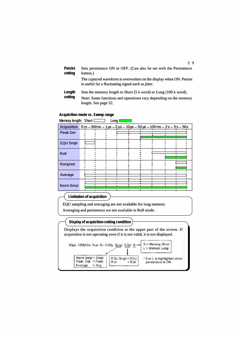
2929
PersistPersistsettingsetting
Sets persistence ON or OFF. (Can also be set with the PersistenceSets persistence ON or OFF. (Can also be set with the Persistencebutton.)button.)
The captured waveform is overwritten on the display when ON. PersistThe captured waveform is overwritten on the display when ON. Persistis useful for a fluctuating signal such as jitter.is useful for a fluctuating signal such as jitter.
LengthLengthsettingsetting
Sets the memory length to Short (5 k word) or Long (100 k word).Sets the memory length to Short (5 k word) or Long (100 k word).
Note: Some functions and operations vary depending on the memoryNote: Some functions and operations vary depending on the memorylength. See page 52.length. See page 52.
Acquisition mode vs. Sweep rangeAcquisition mode vs. Sweep rangeMemory length:Memory length: ShortShort LongLong Acquisition Acquisition 5 ns5 ns↔↔500 ns500 ns↔↔1 µs1 µs↔↔2 µs 2 µs ↔↔ 10 10 µsµs↔↔50 50 µµss↔↔100 ms100 ms↔↔2 s 2 s ↔↔ 5 s 5 s ↔↔ 50 s 50 s Peak Det Peak Det
EQU Smpl EQU Smpl
Roll Roll
Rol Rolll print print
Average Average
Norm Smpl Norm Smpl
Displays the acquisition condition at the upper part of the screen. IfDisplays the acquisition condition at the upper part of the screen. Ifacquisition is not operating even if it is not valid, it is not displayed.acquisition is not operating even if it is not valid, it is not displayed.
Display of acquisition setting conditionDisplay of acquisition setting condition
EQU sampling and averaging are not available for long memory.EQU sampling and averaging are not available for long memory.
Averaging and persistence are not available in Roll mode.Averaging and persistence are not available in Roll mode.
Limitation of acquisitionLimitation of acquisition
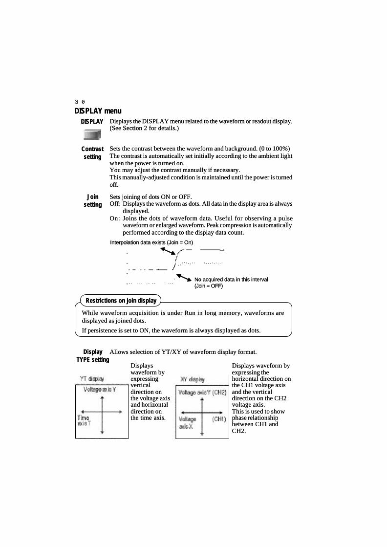
3030
Displays waveform byDisplays waveform byexpressing theexpressing thehorizontal direction onhorizontal direction onthe CH1 voltage axisthe CH1 voltage axisand the verticaland the verticaldirection on the CH2direction on the CH2voltage axis.voltage axis.This is used to showThis is used to showphase relationshipphase relationshipbetween CH1 andbetween CH1 andCH2.CH2.
DISPLAY menuDISPLAY menuDISPLAYDISPLAY Displays the DISPLAY menu related to the waveform or readout display.Displays the DISPLAY menu related to the waveform or readout display.
(See Section 2 for details.)(See Section 2 for details.)
ContrastContrastsettingsetting
JoinJoin setting setting
Sets joining of dots ON or OFF.Sets joining of dots ON or OFF.Off:Off: Displays the waveform as dots. All data in the display area is alwaysDisplays the waveform as dots. All data in the display area is always
displayed.displayed.On:On: Joins the dots of waveform data. Useful for observing a pulseJoins the dots of waveform data. Useful for observing a pulse
waveform or enlarged waveform. Peak compression is automaticallywaveform or enlarged waveform. Peak compression is automaticallyperformed according to the display data count.performed according to the display data count.
DisplayDisplayTYPE settingTYPE setting
Allows selection of YT/XY of waveform display format.Allows selection of YT/XY of waveform display format.
DisplaysDisplayswaveform bywaveform byexpressingexpressingverticalverticaldirection ondirection onthe voltage axisthe voltage axisand horizontaland horizontaldirection ondirection onthe time axis.the time axis.
Sets the contrast between the waveform and background. (0 to 100%)Sets the contrast between the waveform and background. (0 to 100%)The contrast is automatically set initially according to the ambient lightThe contrast is automatically set initially according to the ambient lightwhen the power is turned on.when the power is turned on.You may adjust the contrast manually if necessary.You may adjust the contrast manually if necessary.This manually-adjusted condition is maintained until the power is turnedThis manually-adjusted condition is maintained until the power is turnedoff.off.
Interpolation data exists (Join = On)Interpolation data exists (Join = On)
No acquired data in this intervalNo acquired data in this interval(Join = OFF)(Join = OFF)
While waveform acquisition is under Run in long memory, waveforms areWhile waveform acquisition is under Run in long memory, waveforms aredisplayed as joined dots.displayed as joined dots.
If persistence is set to ON, the waveform is always displayed as dots.If persistence is set to ON, the waveform is always displayed as dots.
Restrictions on join displayRestrictions on join display

3131
ScaleScalesettingsetting
Sets the scale for display (Grid, Axis, Frame) in the waveform displaySets the scale for display (Grid, Axis, Frame) in the waveform displayarea.area.
Example of selecting GridExample of selecting Grid
MathMathsettingsetting
Selects the following 3 types of waveforms cSelects the following 3 types of waveforms calculation.alculation.
Add:Add: Displays addition of the CH1 and CH2 waveforms.Displays addition of the CH1 and CH2 waveforms.Sub:Sub: Displays subtraction of the CH1 and CH2 waveforms.Displays subtraction of the CH1 and CH2 waveforms.Mult:Mult: Displays multiplication of the CH1 and CH2 waveforms.Displays multiplication of the CH1 and CH2 waveforms.
StatusStatus setting setting
Sets one of the following 4 Sets one of the following 4 display items in the temporary display area.display items in the temporary display area.
Counter:Counter: Displays the frequency of a trigger signal.Displays the frequency of a trigger signal.Date:Date: Displays the time and date.Displays the time and date.Measure:Measure: Displays the auto measurement result.Displays the auto measurement result.Comment:Comment: Displays the edited comment.Displays the edited comment.
Comments can be edited by setting the UTILITIES menuComments can be edited by setting the UTILITIES menuto Comment through [FUNCTION operation]. (See pageto Comment through [FUNCTION operation]. (See page39.)39.)
The status display is erased when CH1/CH2 offset is set or a temporaryThe status display is erased when CH1/CH2 offset is set or a temporarymessage is displayed, but can be displayed again by operating the menumessage is displayed, but can be displayed again by operating the menuand functions.and functions.
Grid:Grid:Displays the grid, whichDisplays the grid, whichdivides the vertical directiondivides the vertical directioninto eight divisions and theinto eight divisions and thehorizontal direction into tenhorizontal direction into tendivisions.divisions.The unit of this grid isThe unit of this grid isexpressed as 1DIV. Voltageexpressed as 1DIV. Voltagesensitivity VOLTS/DIV andsensitivity VOLTS/DIV andsweep time range TIME/DIVsweep time range TIME/DIVare set using this as the unit.are set using this as the unit.
Counter measurementCounter measurement
Selecting Counter in Status makes it possible to always measure the frequencySelecting Counter in Status makes it possible to always measure the frequencyof the input signal selected as the trigger signal source.of the input signal selected as the trigger signal source.
The mThe measurement is performed irrespective of waveform acquisition.easurement is performed irrespective of waveform acquisition.
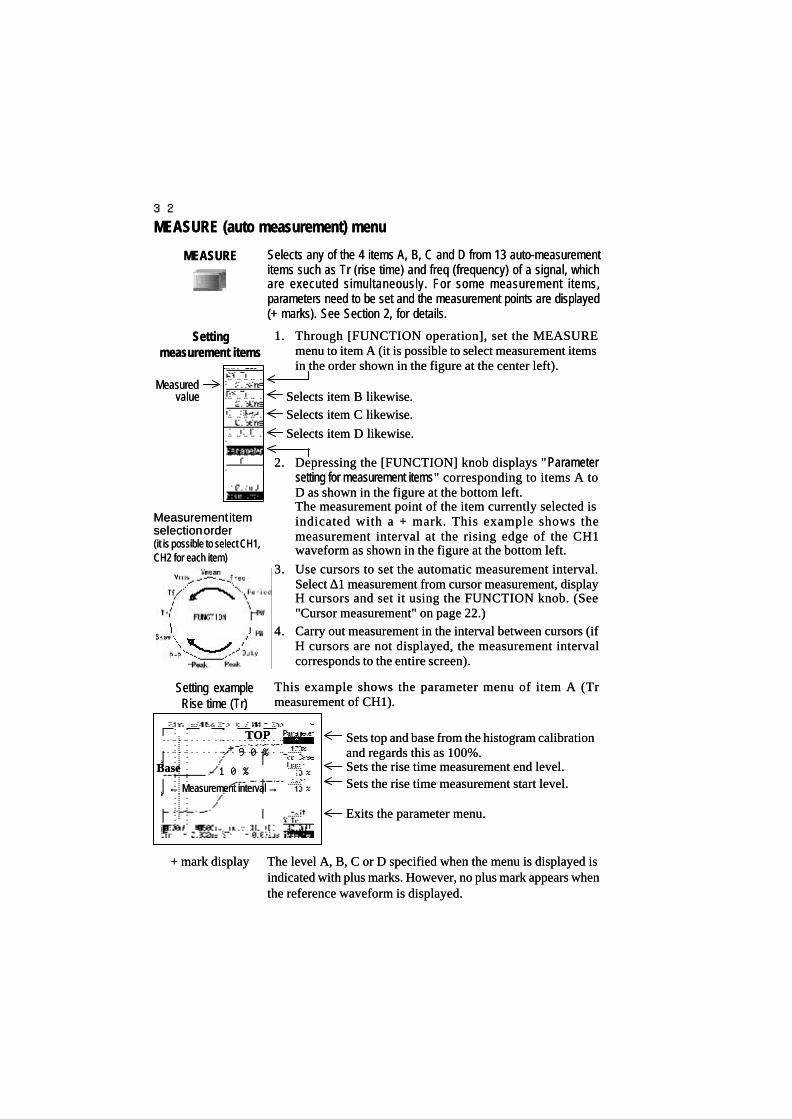
3232
1.1. Through [FUNCTION operation], set the MEASUREThrough [FUNCTION operation], set the MEASUREmenu to item A (it is possible to select measurement itemsmenu to item A (it is possible to select measurement itemsin the order shown in the figure at the center left).in the order shown in the figure at the center left).
Selects item B likewise.Selects item B likewise.Selects item C likewise.Selects item C likewise.
Selects item D likewise.Selects item D likewise.
2.2. Depressing the [FUNCTION] knob displays "Depressing the [FUNCTION] knob displays "ParameterParametersetting for measurement itemssetting for measurement items" corresponding to items A to" corresponding to items A toD as shown in the figure at the bottom left.D as shown in the figure at the bottom left.The measurement point of the item currently selected isThe measurement point of the item currently selected isindicated with a + mark. This example shows theindicated with a + mark. This example shows themeasurement interval at the rising edge of the CH1measurement interval at the rising edge of the CH1waveform as shown in the figure at the bottom left.waveform as shown in the figure at the bottom left.
3.3. Use cursors to set the automatic measurement interval.Use cursors to set the automatic measurement interval.Select Select ∆∆1 measurement from cursor measurement, display1 measurement from cursor measurement, displayH cursors and set it using the FUNCTION knob. (SeeH cursors and set it using the FUNCTION knob. (See"Cursor measurement" on page 22.)"Cursor measurement" on page 22.)
4.4. Carry out measurement in the interval between cursors (ifCarry out measurement in the interval between cursors (ifH cursors are not displayed, the measurement intervalH cursors are not displayed, the measurement intervalcorresponds to the entire screen).corresponds to the entire screen).
MEASURE (auto measurement) menuMEASURE (auto measurement) menu
MEASUREMEASURE Selects any of the 4 items A, B, C and D from 13 auto-measurementSelects any of the 4 items A, B, C and D from 13 auto-measurementitems such as Tr (rise time) and freq (frequency) of a signal, whichitems such as Tr (rise time) and freq (frequency) of a signal, whichare executed simultaneously. For some measurement items,are executed simultaneously. For some measurement items,parameters need to be set and the measurement points are displayedparameters need to be set and the measurement points are displayed(+ marks). See Section 2, for details.(+ marks). See Section 2, for details.
Measurement itemMeasurement itemselection orderselection order(it is possible to select CH1,(it is possible to select CH1,CH2 for each item)CH2 for each item)
SettingSettingmeasurement itemsmeasurement items
This example shows the parameter menu of item A (TrThis example shows the parameter menu of item A (Trmeasurement of CH1).measurement of CH1).
The level A, B, C or D specified when the menu is displayed isThe level A, B, C or D specified when the menu is displayed isindicated with plus marks. However, no plus mark appears whenindicated with plus marks. However, no plus mark appears whenthe reference waveform is displayed.the reference waveform is displayed.
Setting exampleSetting exampleRise time (Tr)Rise time (Tr)
+ mark display+ mark display
TOPTOP90%90%
BaseBase 10%10%
←← Measurement interval Measurement interval →→
Sets top and base from the histogram calibrationSets top and base from the histogram calibrationand regards this as 100%.and regards this as 100%.Sets the rise time measurement end level.Sets the rise time measurement end level.Sets the rise time measurement start level.Sets the rise time measurement start level.
Exits the parameter menu.Exits the parameter menu.
MeasuredMeasuredvaluevalue
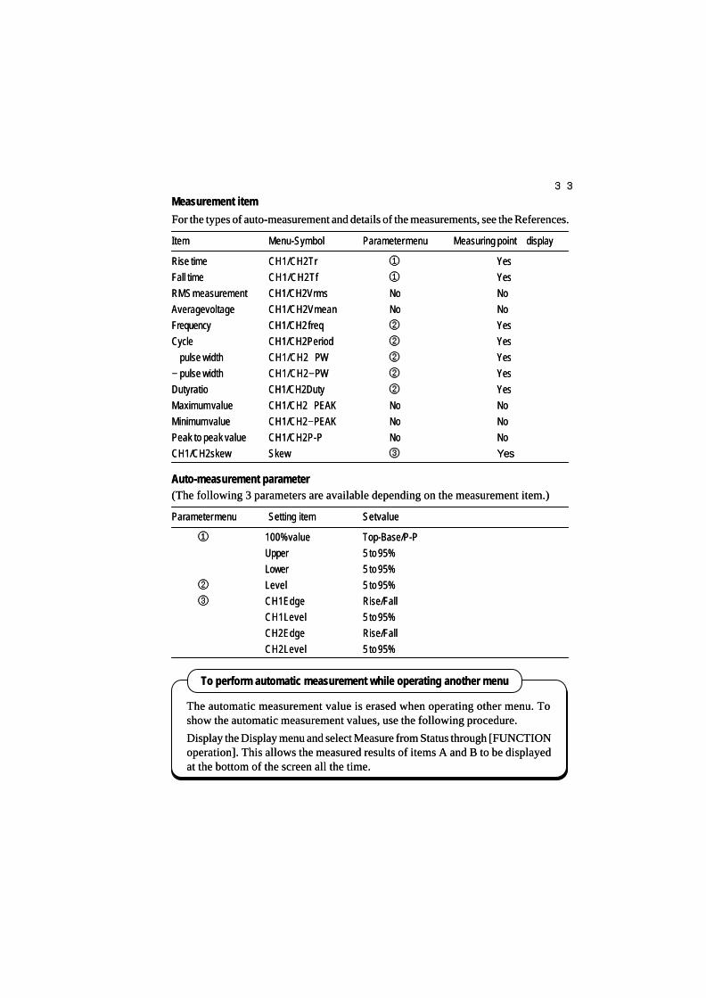
3333
To perform automatic measurement while operating another menuTo perform automatic measurement while operating another menu
The automatic measurement value is erased when operating other menu. ToThe automatic measurement value is erased when operating other menu. Toshow the automatic measurement values, use the following procedure.show the automatic measurement values, use the following procedure.
Display the Display menu and select Measure from Status through [FUNCTIONDisplay the Display menu and select Measure from Status through [FUNCTIONoperation]. This allows the measured results of items A and B to be displayedoperation]. This allows the measured results of items A and B to be displayedat the bottom of the screen all the time.at the bottom of the screen all the time.
ItemItem Menu-SymbolMenu-Symbol Parameter menuParameter menu Measuring point Measuring point ++ display display
Rise timeRise time CH1/CH2 TrCH1/CH2 Tr ①① YesYesFall timeFall time CH1/CH2 TfCH1/CH2 Tf ①① YesYesRMS measurementRMS measurement CH1/CH2 VrmsCH1/CH2 Vrms NoNo NoNoAverage voltageAverage voltage CH1/CH2 VmeanCH1/CH2 Vmean NoNo NoNoFrequencyFrequency CH1/CH2 freqCH1/CH2 freq ②② YesYesCycleCycle CH1/CH2 PeriodCH1/CH2 Period ②② YesYes++ pulse width pulse width CH1/CH2 CH1/CH2 ++PWPW ②② YesYes− − pulse widthpulse width CH1/CH2 CH1/CH2 −−PWPW ②② YesYesDuty ratioDuty ratio CH1/CH2 DutyCH1/CH2 Duty ②② YesYesMaximum valueMaximum value CH1/CH2 CH1/CH2 ++PEAKPEAK NoNo NoNoMinimum valueMinimum value CH1/CH2 CH1/CH2 −−PEAKPEAK NoNo NoNoPeak to peak valuePeak to peak value CH1/CH2 P-PCH1/CH2 P-P NoNo NoNoCH1/CH2 skewCH1/CH2 skew SkewSkew ③③ YesYes
Measurement itemMeasurement itemFor the types of auto-measurement and details of the measurements, see the References.For the types of auto-measurement and details of the measurements, see the References.
(The following 3 parameters are available depending on the measurement item.)(The following 3 parameters are available depending on the measurement item.)Auto-measurement parameterAuto-measurement parameter
Parameter menuParameter menu Setting itemSetting item Set valueSet value
①① 100% value100% value Top-Base/P-PTop-Base/P-PUpperUpper 5 to 95%5 to 95%LowerLower 5 to 95%5 to 95%
②② LevelLevel 5 to 95%5 to 95%③③ CH1 EdgeCH1 Edge Rise/FallRise/Fall
CH1 LevelCH1 Level 5 to 95%5 to 95%CH2 EdgeCH2 Edge Rise/FallRise/FallCH2 LevelCH2 Level 5 to 95%5 to 95%
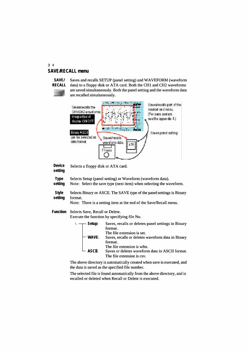
3434
SAVE/RECALL menuSAVE/RECALL menu
SAVE/SAVE/RECALLRECALL
DeviceDevicesettingsetting
TypeTypesettingsetting
FunctionFunction
StyleStylesettingsetting
Saves and recalls SETUP (panel setting) and WAVEFORM (waveformSaves and recalls SETUP (panel setting) and WAVEFORM (waveformdata) to a floppy disk or ATA card. Both the CH1 and CH2 waveformsdata) to a floppy disk or ATA card. Both the CH1 and CH2 waveformsare saved simultaneously. Both the panel setting and the waveform dataare saved simultaneously. Both the panel setting and the waveform dataare recalled simultaneously.are recalled simultaneously.
Selects a floppy disk or ATA card.Selects a floppy disk or ATA card.
Selects Setup (panel setting) or Waveform (waveform data).Selects Setup (panel setting) or Waveform (waveform data).Note:Note: Select the save type (next item) when selecting the waveform.Select the save type (next item) when selecting the waveform.
Selects Binary or ASCII. The SAVE type of the panelSelects Binary or ASCII. The SAVE type of the panel settings is Binarysettings is Binaryformat.format.Note:Note: There is a setting item at the end of the Save/Recall menu.There is a setting item at the end of the Save/Recall menu.
Selects Save, Recall or Delete.Selects Save, Recall or Delete.Execute the function by specifying file No.Execute the function by specifying file No.
\\ SetupSetup:: Saves, recalls or deletes panel settings in BinarySaves, recalls or deletes panel settings in Binaryformat.format.The file extension is set.The file extension is set.
WAVEWAVE:: Saves, recalls or deletes waveform data in BinarySaves, recalls or deletes waveform data in Binaryformat.format.The file extension is wfm.The file extension is wfm.
ASCIIASCII:: Saves or deletes waveform data in ASCII format.Saves or deletes waveform data in ASCII format.The file extension is csv.The file extension is csv.
The above directory is automatically created when save is executed, andThe above directory is automatically created when save is executed, andthe data is saved as the specified file number.the data is saved as the specified file number.
The selected file is found automatically from the above directory, and isThe selected file is found automatically from the above directory, and isrecalled or deleted when Recall or Delete is executed.recalled or deleted when Recall or Delete is executed.

3535
Saving panel settings to floppy diskSaving panel settings to floppy disk
Recalling panel settings from floppyRecalling panel settings from floppy1 to 3.1 to 3. Set in the same way as “Save panel setting to floppy disk.”Set in the same way as “Save panel setting to floppy disk.”
4.4. Select Recall in Function with [Function operation].Select Recall in Function with [Function operation].5.5. Specify the File No. with [Function operation]. (e.g. specify “1”).Specify the File No. with [Function operation]. (e.g. specify “1”).
All saved files are displayed. When the panel setting is recalled, onlyAll saved files are displayed. When the panel setting is recalled, onlyfile No. of existing files are selected and displayed.file No. of existing files are selected and displayed.You can set the file No. in steps of 10 when Course is set.You can set the file No. in steps of 10 when Course is set.If there is no file, “*****” is displayed.If there is no file, “*****” is displayed.
6.6. After specifying the File No., press the FUNCTION knob. TheAfter specifying the File No., press the FUNCTION knob. Themessage “Press FUNCTION to recall” appears. Press the knob againmessage “Press FUNCTION to recall” appears. Press the knob againto execute RECALL.to execute RECALL.
It is possible to save the panel settings and waveform data (Binary/ASCII) inIt is possible to save the panel settings and waveform data (Binary/ASCII) infiles (No.1 to 200).files (No.1 to 200).It is also possible to save the panel settings and waveform data (Binary/ASCII)It is also possible to save the panel settings and waveform data (Binary/ASCII)in an ATA Card (No.1 to 9999).in an ATA Card (No.1 to 9999).The number of files that can be saved depends on the remaining capacity of aThe number of files that can be saved depends on the remaining capacity of afloppy disk or ATA card.floppy disk or ATA card.
Number and capacity of files that can be savedNumber and capacity of files that can be saved
Type of fileType of file File capacityFile capacity Storage timeStorage time
Panel settingPanel setting 1 kB1 kB Approx. 5 sec.Approx. 5 sec.Waveform data for short memory (Binary)Waveform data for short memory (Binary) 11 kB11 kB Approx. 12 sec.Approx. 12 sec.Waveform data for short memory (ASCII)Waveform data for short memory (ASCII) 56 kB (max.)56 kB (max.) Approx. 30 sec.Approx. 30 sec.Waveform data for long memory (Binary)Waveform data for long memory (Binary) 201 kB201 kB Approx. 90 sec.Approx. 90 sec.Waveform data for long memory (ASCII)Waveform data for long memory (ASCII) 1101 kB (max.)1101 kB (max.) Approx. 9 min.Approx. 9 min.
1.1. Press the SAVE/RECALL button to display the SAVE/RECALL menu.Press the SAVE/RECALL button to display the SAVE/RECALL menu.2.2. Set Device to Floppy with [Function operation].Set Device to Floppy with [Function operation].3.3. Set Type to Setup (panel setting) with [Function operation].Set Type to Setup (panel setting) with [Function operation].4.4. Set Function to Save with [Function operation].Set Function to Save with [Function operation].5.5. Specify the File No. (e.g. specify “1”).Specify the File No. (e.g. specify “1”).
You can set the file No. in steps of 10 when Course is set.You can set the file No. in steps of 10 when Course is set.6.6. After specifying the File No., press the FUNCTION knob.After specifying the File No., press the FUNCTION knob.
The message “Press FUNCTION to save” appears.The message “Press FUNCTION to save” appears.Press the knob again to execute SAVE.Press the knob again to execute SAVE.If the specified file already exists, the message “Press FUNCTIONIf the specified file already exists, the message “Press FUNCTIONagain to overwrite” appears.again to overwrite” appears.Press the FUNCTION knob again.Press the FUNCTION knob again.

3636
Saving waveform to floppy diskSaving waveform to floppy disk
Recalling waveform data from floppy diskRecalling waveform data from floppy disk
Do not operate any other function while the scope is accessing theDo not operate any other function while the scope is accessing thefloppy disk (green lamp is lit).floppy disk (green lamp is lit).
Operation during floppy disk accessOperation during floppy disk access
1.1. Press the SAVE/RECALL button to display the SAVE/RECALLPress the SAVE/RECALL button to display the SAVE/RECALLmenu.menu.
2.2. Set Device to Floppy with [Function operation].Set Device to Floppy with [Function operation].
3.3. Set Type to Waveform with [Function operation].Set Type to Waveform with [Function operation].4.4. Set Style to Binary with [Function operation].Set Style to Binary with [Function operation].
5.5. Set Function to Save with [Function operation].Set Function to Save with [Function operation].6.6. Specify the File No. with [Function operation] (e.g. specify “1”).Specify the File No. with [Function operation] (e.g. specify “1”).
You can set the file No. in steps of 10 when Course is set.You can set the file No. in steps of 10 when Course is set.
7.7. After specifying the File No., press the FUNCTION knob.After specifying the File No., press the FUNCTION knob.The message “Press the FUNCTION knob to save” appears.The message “Press the FUNCTION knob to save” appears.
Press the knob again to execute SAVE.Press the knob again to execute SAVE.If the specified file already exists, the message “Press theIf the specified file already exists, the message “Press theFUNCTION knob again to overwrite” appears.FUNCTION knob again to overwrite” appears.Press the FUNCTION knob again.Press the FUNCTION knob again.
Note:Note: Saving or recalling waveform data saves or recalls both theSaving or recalling waveform data saves or recalls both theCH1 and CH2 waveform data at the same time without anyCH1 and CH2 waveform data at the same time without anyrelation to whether trace is ON or OFF.relation to whether trace is ON or OFF.
1 to 4.1 to 4. Set in the same way as saving waveform data to floppy disk.Set in the same way as saving waveform data to floppy disk.
5.5. Select Recall in Function with [Function operation].Select Recall in Function with [Function operation].
6.6. Specify the File No. with [Function operation] (e.g. specify “1”).Specify the File No. with [Function operation] (e.g. specify “1”).All saved files are displayed. When the waveform data is recalled,All saved files are displayed. When the waveform data is recalled,only file No. of files in which the data was saved are selected andonly file No. of files in which the data was saved are selected anddisplayed.displayed.You can set the file No. in steps of 10 when Course is set.You can set the file No. in steps of 10 when Course is set.
If there is no file, “*****” is displayed.If there is no file, “*****” is displayed.7.7. After specifying the File No., press the FUNCTION knob. TheAfter specifying the File No., press the FUNCTION knob. The
message “Press FUNCTION to recall” appears. Press the knobmessage “Press FUNCTION to recall” appears. Press the knobagain to execute RECALL.again to execute RECALL.

3737
Save/Recall menu (continuation)Save/Recall menu (continuation)
Auto saveAuto save
FormatFormatsettingsetting
DefaultDefault
DeleteDelete
Waveform data format (Style)Waveform data format (Style)
Binary coded waveform data (CH1/CH2) is saved with the panel settings, timeBinary coded waveform data (CH1/CH2) is saved with the panel settings, timeand comment.and comment.
In Binary format, the data is saved as binary data. The saved data is recalled byIn Binary format, the data is saved as binary data. The saved data is recalled bythe scope.the scope.
ASCII waveform data (CH1/CH2) is saved in CSV format with limited panelASCII waveform data (CH1/CH2) is saved in CSV format with limited panelsettings and time. (CSV: Comma Separated Value)settings and time. (CSV: Comma Separated Value)
ASCII data can be displayed using Windows applications such as Excel (notASCII data can be displayed using Windows applications such as Excel (notprovided with the scope).provided with the scope).
Formats a medium inserted to a specified device. Note that formattingFormats a medium inserted to a specified device. Note that formattingthe medium will erase all data saved in the medium. Using a mediumthe medium will erase all data saved in the medium. Using a mediumsuch as floppy disk or ATA card requires formatting.such as floppy disk or ATA card requires formatting.
Formatting the floppy diskFormatting the floppy disk
The format operation erases all stored data.The format operation erases all stored data.
1.1. Set Format to Floppy with [Function operation].Set Format to Floppy with [Function operation].
2.2. Press the FUNCTION knob. The message “Push the FK to formatPress the FUNCTION knob. The message “Push the FK to formatFloppy” appears.Floppy” appears.
Press the knob again to execute formatting.Press the knob again to execute formatting.
Note:Note: Before using a new floppy disk or ATA card, the deviceBefore using a new floppy disk or ATA card, the devicemust be formatted.must be formatted.
Saves waveform data to the specified device sequentially when a newSaves waveform data to the specified device sequentially when a newwaveform is captured.waveform is captured.
Press ON to start Auto save.Press ON to start Auto save.
Press STOP to stop Auto save.Press STOP to stop Auto save.
Press RUN to restart Auto save.Press RUN to restart Auto save.
When the Auto save function is active, all operations except RUN/When the Auto save function is active, all operations except RUN/STOP are ignored.STOP are ignored.
During Auto execution, the data is saved as binary data.During Auto execution, the data is saved as binary data.
Resets the settings to the factory settings. (See page 10.)Resets the settings to the factory settings. (See page 10.)
Deletes the specified file.Deletes the specified file.

3838
UTILITIES menuUTILITIES menu
UTILITIESUTILITIES Displays the Copy, Interface, Comment, Date or Config menu.Displays the Copy, Interface, Comment, Date or Config menu.
Copy menuCopy menusettingsetting
Output deviceOutput device MenuMenu Output formatOutput format Output sourceOutput source
Built-in printerBuilt-in printer PrinterPrinter - - -- - - Screen, Panel SetupScreen, Panel SetupFloppy diskFloppy disk FloppyFloppy BMP, TIFFBMP, TIFF Screen, Panel SetupScreen, Panel SetupATA cardATA card ATA CARDATA CARD BMP, TIFFBMP, TIFF Screen, Panel SetupScreen, Panel SetupCentronicsCentronics CentroCentro DPU-414DPU-414 Screen, Panel SetupScreen, Panel Setup
ESC-P09ESC-P09ESC-P24ESC-P24PC-PR201PC-PR201
A hard copy of the screen can be output when the output destination isA hard copy of the screen can be output when the output destination isset to the screen, and the setup settings can be output when the outputset to the screen, and the setup settings can be output when the outputdestination is set to the panel.destination is set to the panel.
The File No. can be specified when the output destination is set to floppyThe File No. can be specified when the output destination is set to floppydisk or ATA card.disk or ATA card.
The file No. is incremented by 1 automatically after copying by pressingThe file No. is incremented by 1 automatically after copying by pressingthe Copy button.the Copy button.
InterfaceInterfacemenumenu
settingsetting
Selects a device or sets the output format (Style) and output destinationSelects a device or sets the output format (Style) and output destination(Source), etc.(Source), etc.
Sets the delimiter, baud rate and data length (Data) of the RS-232C (noSets the delimiter, baud rate and data length (Data) of the RS-232C (noparity, stop bit is 1 bit).parity, stop bit is 1 bit).
When the DS-534 GP-IB Card is inserted to the card slot, any addressWhen the DS-534 GP-IB Card is inserted to the card slot, any addressand the delimiter can be set by the GP-IB menu.and the delimiter can be set by the GP-IB menu.
Example whereExample whereFloppy is selected fromFloppy is selected fromDevice in Copy menuDevice in Copy menu
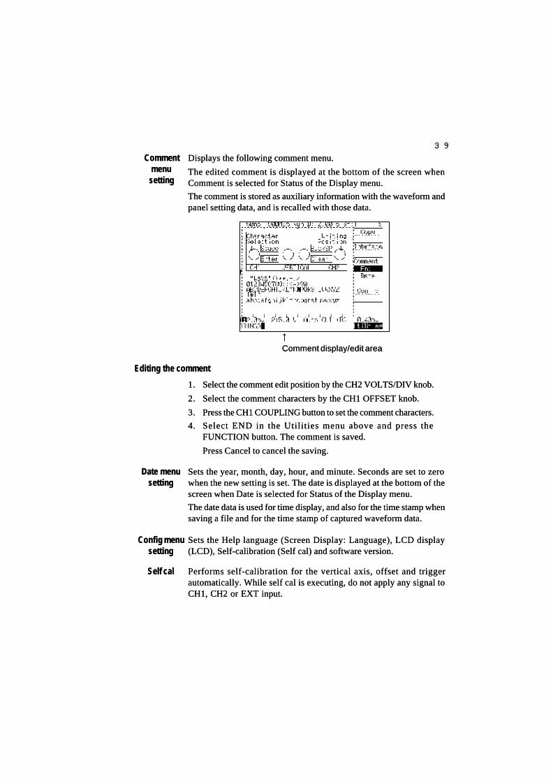
3939
CommentCommentmenumenu
settingsetting
Displays the following comment menu.Displays the following comment menu.
The edited comment is displayed at the bottom of the screen whenThe edited comment is displayed at the bottom of the screen whenComment is selected for Status of the Display menu.Comment is selected for Status of the Display menu.
The comment is stored as auxiliary information with the waveform andThe comment is stored as auxiliary information with the waveform andpanel setting data, and is recalled with those data.panel setting data, and is recalled with those data.
Sets the year, month, day, hour, and minute. Seconds are set to zeroSets the year, month, day, hour, and minute. Seconds are set to zerowhen the new setting is set. The date is displayed at the bottom of thewhen the new setting is set. The date is displayed at the bottom of thescreen when Date is selected for Status of the Display menu.screen when Date is selected for Status of the Display menu.
The date data is used for time display, and also for the time stamp whenThe date data is used for time display, and also for the time stamp whensaving a file and for the time stamp of captured waveform data.saving a file and for the time stamp of captured waveform data.
Date menuDate menusettingsetting
Config menuConfig menusettingsetting
Self calSelf cal
↑↑
Comment display/edit areaComment display/edit area
Editing the commentEditing the comment
1.1. Select the comment edit position by the CH2 VOLTS/DIV knob.Select the comment edit position by the CH2 VOLTS/DIV knob.
2.2. Select the comment characters by the CH1 OFFSET knob.Select the comment characters by the CH1 OFFSET knob.
3.3. Press the CH1 COUPLING button to set the comment characters.Press the CH1 COUPLING button to set the comment characters.
4.4. Select END in the Utilities menu above and press theSelect END in the Utilities menu above and press theFUNCTION button. The comment is saved.FUNCTION button. The comment is saved.
Press Cancel to cancel the saving.Press Cancel to cancel the saving.
Sets the Help language (Screen Display: Language), LCD displaySets the Help language (Screen Display: Language), LCD display(LCD), Self-calibration (Self cal) and software version.(LCD), Self-calibration (Self cal) and software version.
Performs self-calibration for the vertical axis, offset and triggerPerforms self-calibration for the vertical axis, offset and triggerautomatically. While self cal is executing, do not apply any signal toautomatically. While self cal is executing, do not apply any signal toCH1, CH2 or EXT input.CH1, CH2 or EXT input.

4040
MemoMemo

4141
Section 2Section 2 Explanation of FunctionsExplanation of Functions
This section gives detailed explanations of functions.This section gives detailed explanations of functions.
PagePage
Waveform displayWaveform display 4242
Vertical axisVertical axis 4343
Horizontal axisHorizontal axis 4343
SynchronizationSynchronization 4444
TV triggerTV trigger 4646
ACQUISITIONACQUISITION 4747
Peak detection (Peak Det)Peak detection (Peak Det) 4747
Average (Average)Average (Average) 4848
Equivalent sampling (EQU SMPL)Equivalent sampling (EQU SMPL) 4949
Roll (ROLL)Roll (ROLL) 5050
Persistence (PERSISTENCE)Persistence (PERSISTENCE) 5252
XY displayXY display 5353
Calculated waveformCalculated waveform 5454
Automatic measurement (MEASURE)Automatic measurement (MEASURE) 5555
Save/recall/deleteSave/recall/delete 6060
UTILITIES/CopyUTILITIES/Copy 6262
AppendicesAppendices 6464
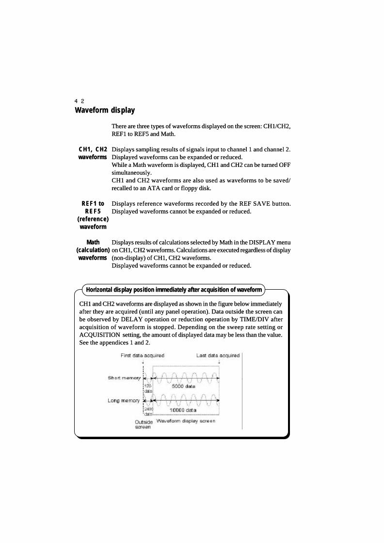
4242
Waveform displayWaveform display
There are three types of waveforms displayed on the screen: CH1/CH2,There are three types of waveforms displayed on the screen: CH1/CH2,REF1 to REF5 and Math.REF1 to REF5 and Math.
Displays sampling results of signals input to channel 1 and channel 2.Displays sampling results of signals input to channel 1 and channel 2.Displayed wDisplayed waveforms can be expanded or reduced.aveforms can be expanded or reduced.While a Math waveform is displayed, CH1 and CH2 can be turned OFFWhile a Math waveform is displayed, CH1 and CH2 can be turned OFFsimultaneously.simultaneously.CH1 and CH2 waveforms are also used as waveforms to be saved/CH1 and CH2 waveforms are also used as waveforms to be saved/recalled to an ATA card or floppy disk.recalled to an ATA card or floppy disk.
Displays reference waveforms recorded by the REF SAVE button.Displays reference waveforms recorded by the REF SAVE button.Displayed waveforms cannot be expanded or reduced.Displayed waveforms cannot be expanded or reduced.
Displays results of calculations selected by Math in the DISPLAY menuDisplays results of calculations selected by Math in the DISPLAY menuon CH1, CH2 waveforms. Calculations are executed regardless of displayon CH1, CH2 waveforms. Calculations are executed regardless of display(non-display) of CH1, CH2 waveforms.(non-display) of CH1, CH2 waveforms.Displayed waveforms cannot be expanded or reduced.Displayed waveforms cannot be expanded or reduced.
Horizontal display position immediately after acquisition of waveformHorizontal display position immediately after acquisition of waveform
CH1 and CH2 waveforms are displayed as shown in the figure below immediatelyCH1 and CH2 waveforms are displayed as shown in the figure below immediatelyafter they are acquired (until any panel operation). Data outside the screen canafter they are acquired (until any panel operation). Data outside the screen canbe observed by DELAY operation or reduction operation by TIME/DIV afterbe observed by DELAY operation or reduction operation by TIME/DIV afteracquisition of waveform is stopped. Depending on the sweep rate setting oracquisition of waveform is stopped. Depending on the sweep rate setting orACQUISITION setting, the amount of displayed data may be less than the value.ACQUISITION setting, the amount of displayed data may be less than the value.See the appendices 1 and 2.See the appendices 1 and 2.
CH1, CH2CH1, CH2waveformswaveforms
REF1 toREF1 toREF5REF5
(reference)(reference)waveformwaveform
MathMath(calculation)(calculation)waveformswaveforms

4343
Vertical axisVertical axis
Selects an attenuation ratio of the probe used by the probe setting inSelects an attenuation ratio of the probe used by the probe setting inthe CH1, CH2 menu from 1:1, 10:1, 100:1 and 1000:1.the CH1, CH2 menu from 1:1, 10:1, 100:1 and 1000:1.Selecting Auto automatically recognizes the probe with a probe senseSelecting Auto automatically recognizes the probe with a probe sensefunction (1/10, 1/100) and sets an attenuation ratio.function (1/10, 1/100) and sets an attenuation ratio.When using the probe, set Auto. The deflection factor is convertedWhen using the probe, set Auto. The deflection factor is convertedand displayed depending on the attenuation ratio.and displayed depending on the attenuation ratio.The converted value is reflected in cursor measurement and autoThe converted value is reflected in cursor measurement and automeasurement, etc.measurement, etc.
Horizontal axisHorizontal axis
The setting range for a trigger delay in a waveform acquisition (RUN)The setting range for a trigger delay in a waveform acquisition (RUN)state varies depending on the sweep time and memory length.state varies depending on the sweep time and memory length.The waveform acquisition stop (STOP) state isThe waveform acquisition stop (STOP) state is − −500 s to +750 s500 s to +750 sregardless of sweep time and memory length.regardless of sweep time and memory length.
Trigger delay setting range (RUN state)Trigger delay setting range (RUN state)
Memory lengthMemory length Sweep timeSweep time Setting rangeSetting range
ShortShort 5 ns to 1 ms/div5 ns to 1 ms/div −−5 div to +10 ms5 div to +10 ms2 ms to 50 s/div2 ms to 50 s/div −−5 div to +500 s5 div to +500 s
LongLong 5 ns to 20 ms/div5 ns to 20 ms/div −−5 div to +200 ms5 div to +200 ms50 ms to 50 s/div50 ms to 50 s/div −−5 div to +500 s5 div to +500 s
In the RUN state, the time from the triggerIn the RUN state, the time from the triggerpoint to the center of the waveform screenpoint to the center of the waveform screenis set.is set.
The STOP state is used to move an acquired waveform in horizontal direction.The STOP state is used to move an acquired waveform in horizontal direction.See page 16 for Post trigger and Pre trigger.See page 16 for Post trigger and Pre trigger.
ProbeProbesettingsetting
DELAYDELAY

4444
SynchronizationSynchronization
Specifies trigger count or trigger period (interval time setting), andSpecifies trigger count or trigger period (interval time setting), andgenerates valid trigger signal and acquires waveform only a specificgenerates valid trigger signal and acquires waveform only a specificcondition is satisfied.condition is satisfied.
Selects Count, Burst, Extra or Missing as event type.Selects Count, Burst, Extra or Missing as event type.
Generates valid trigger signal every specified count of trigger signal. ItGenerates valid trigger signal every specified count of trigger signal. Itis suitable for operation check of counter circuit.is suitable for operation check of counter circuit.Count setting: 1 to 9999 (selecting Coarse allows setting every 100Count setting: 1 to 9999 (selecting Coarse allows setting every 100steps)steps)
Generates valid trigger signal when trigger signal period exceeds theGenerates valid trigger signal when trigger signal period exceeds theinterval time. It is suitable for observation of burst waveforms, etc.interval time. It is suitable for observation of burst waveforms, etc.Interval time: 0.15 Interval time: 0.15 µµs to 1 s (can also be set roughly by Coarse)s to 1 s (can also be set roughly by Coarse)
Generates valid trigger signal when trigger signal period is smaller thanGenerates valid trigger signal when trigger signal period is smaller thanthe interval time.the interval time.Acquires waveform when the trigger period is shortened by glitch in aAcquires waveform when the trigger period is shortened by glitch in aclock signal or spike noise in the power line. It is suitable for observationclock signal or spike noise in the power line. It is suitable for observationof glitches.of glitches.Interval time: 0.20 Interval time: 0.20 µµs to 1 s (can also be set roughly by Coarse)s to 1 s (can also be set roughly by Coarse)
To start operationTo start operation
PressPress
RUN/STOP button.RUN/STOP button.
E V E N TE V E N Ttriggertrigger
Type settingType setting
E X T R AE X T R A
CountCount(COUNT)(COUNT)
BurstBurst(BURST)(BURST)

4545
Selects Normal or Single.Selects Normal or Single.
Selects Event.Selects Event.
Selects Burst.Selects Burst.
Sets interval timeSets interval time
Generates a trigger signal at theGenerates a trigger signal at thefalling edge (Neg) of signal.falling edge (Neg) of signal.
Automatically generates valid trigger signal when there is no triggerAutomatically generates valid trigger signal when there is no triggersignal within specified time. The valid trigger is generated within 50nssignal within specified time. The valid trigger is generated within 50nsafter the interval time has passed from the last trigger. It allows waveformafter the interval time has passed from the last trigger. It allows waveformto be acquired when part of repetition signal is missing due to powerto be acquired when part of repetition signal is missing due to powerinterruption or data dropout.interruption or data dropout.Interval time: 0.25 Interval time: 0.25 µµs to 1 s (can also be set roughly by Coarse)s to 1 s (can also be set roughly by Coarse)
Example of Burst signalExample of Burst signal Signal cycleSignal cycle 360 360 µµssStop periodStop period 1.6 ms1.6 ms
Indicates the sweep mode selected.Indicates the sweep mode selected.
Auto:Auto: AutoAuto
Normal:Normal: NormNorm
Single:Single: SnglSngl
TriggerTrigger
Sweep mode when EVENT trigger is usedSweep mode when EVENT trigger is used
When using an EVENT trigger, set the sweep mode to Normal or Single.When using an EVENT trigger, set the sweep mode to Normal or Single.
If Auto is set, waveforms are acquired automatically even if it does not satisfyIf Auto is set, waveforms are acquired automatically even if it does not satisfythe specified condition and it is not possible to acquire the specified phenomenonthe specified condition and it is not possible to acquire the specified phenomenoncorrectly.correctly.
MISSINGMISSING

4646
TV triggerTV trigger
displays NTSC or PAL (SECAM). It generates trigger in the selecteddisplays NTSC or PAL (SECAM). It generates trigger in the selectedfield (Both, Odd, Even) or line.field (Both, Odd, Even) or line.
Selects field and horizontal synchronization.Selects field and horizontal synchronization.Both:Both: Triggers by selecting a line number of horizontal sync signalTriggers by selecting a line number of horizontal sync signal
from vertical odd field or even field.from vertical odd field or even field.Odd:Odd: Triggers by selecting a line number of horizontal sync signalTriggers by selecting a line number of horizontal sync signal
from vertical odd field.from vertical odd field.Even:Even: Triggers by selecting a line number of horizontal sync signalTriggers by selecting a line number of horizontal sync signal
from vertical even field.from vertical even field.TV-H:TV-H: Triggers by a horizontal sync signal.Triggers by a horizontal sync signal.
Specifies a line number in the field selected by Type.Specifies a line number in the field selected by Type.While NTSC is selected: 5 to 2000 can be set.While NTSC is selected: 5 to 2000 can be set.While PAL (SECAM) is selected: 2 to 2000 can be set.While PAL (SECAM) is selected: 2 to 2000 can be set.Lines can also be set with Coarse in 100 steps.Lines can also be set with Coarse in 100 steps.
Selects a signal source to be triggered.Selects a signal source to be triggered.CH1, CH2 or EXT can be set.CH1, CH2 or EXT can be set.
Selects a trigger slope plus (Pos) or minus (Neg) of a TV sync signal.Selects a trigger slope plus (Pos) or minus (Neg) of a TV sync signal.Slope is always performed minus (Neg) when Type is selected TV.Slope is always performed minus (Neg) when Type is selected TV.
Example of measurement with line No. 24 of odd field (Odd) of NTSCExample of measurement with line No. 24 of odd field (Odd) of NTSCsignalsignal
TV triggerTV trigger
TypeType
LineLine
SourceSource
SlopeSlope
TV system and featuresTV system and features
SystemSystem
NTSCNTSC
SECAMSECAM
PALPAL
HDTVHDTV
Line numberLine number
525525
625625
625625
1,1251,125
Field frequencyField frequency
Approx. 60 HzApprox. 60 Hz
Approx. 50 HzApprox. 50 Hz
Approx. 50 HzApprox. 50 Hz
Approx. 60 HzApprox. 60 Hz
Video signalVideo signalbandwidthbandwidth4.2 MHz4.2 MHz
6 MHz6 MHz
5 MHz5 MHz
20 MHz20 MHz
CountryCountry
USA, Canada, Japan,USA, Canada, Japan,Korea, Taiwan,Korea, Taiwan,Philippine, M,S-AmericaPhilippine, M,S-America
France, Russia, E-France, Russia, E-EuropeEurope
W-Europe, Asia, India,W-Europe, Asia, India,OceaniaOceania(Reference)(Reference)

4747
ACQUISITIONACQUISITION
Detects Max./Min. of an input signal by capturing the input signal inDetects Max./Min. of an input signal by capturing the input signal in500 M samples/s and alternately records the Max and Min values in500 M samples/s and alternately records the Max and Min values inmemory in a period corresponding to the sweep time (see Appendicesmemory in a period corresponding to the sweep time (see Appendices1 and 2).1 and 2).If the sweep time is set to 10 If the sweep time is set to 10 µµs/div (5 M samples/s) with short memory,s/div (5 M samples/s) with short memory,it is not possible to capture the waveform peak A in the figure belowit is not possible to capture the waveform peak A in the figure belowwhich occurred in the sampling interval without peak detection.which occurred in the sampling interval without peak detection.Peak detection always captures waveforms in 2 ns period (500 M samples/Peak detection always captures waveforms in 2 ns period (500 M samples/s) irrespective of the set sampling period and alternately records Max./s) irrespective of the set sampling period and alternately records Max./Min. as data, making it possible to capture phenomena that occur in theMin. as data, making it possible to capture phenomena that occur in thesampling period correctly.sampling period correctly.
Pulse signalPulse signal Example of measurement of 10 ns pulse signal with repetition frequencyExample of measurement of 10 ns pulse signal with repetition frequencyof approx.11 kHzof approx.11 kHz
Peak detection mode is OFFPeak detection mode is OFF In peak detection modeIn peak detection mode
Since the pulse width (10 ns) of the signal is 1/10Since the pulse width (10 ns) of the signal is 1/10of the sampling period (100 ns), the pulse signalof the sampling period (100 ns), the pulse signalcannot be captured completely.cannot be captured completely.
Since sampling is always performed in 2Since sampling is always performed in 2ns period, pulses in the sampling periodns period, pulses in the sampling period(100 ns) are captured correctly.(100 ns) are captured correctly.
PeakPeakdetectiondetection(Peak Det)(Peak Det)

4848
Every capturing of an input signal averages data on the same time axisEvery capturing of an input signal averages data on the same time axisand displays the waveform.and displays the waveform.
Selecting Average shows the Count on the menu. Set an averageSelecting Average shows the Count on the menu. Set an averagecount (2, 4, 8, 16, 32, 64, 128 and 256) depending on the waveformcount (2, 4, 8, 16, 32, 64, 128 and 256) depending on the waveformcondition.condition.The greater the count, the greater the effect of eliminating noise in theThe greater the count, the greater the effect of eliminating noise in thesignal becomes, but processing takes more time.signal becomes, but processing takes more time.
Example of measurement when averaging is not performedExample of measurement when averaging is not performed
Example of measurement when averaging is performedExample of measurement when averaging is performed
Noise in the signal is eliminated by averaging.Noise in the signal is eliminated by averaging.
Averaging restrictionsAveraging restrictions
In the roll mode or long memory, Norm smpl (normal sampling) is set automaticallyIn the roll mode or long memory, Norm smpl (normal sampling) is set automaticallyeven if Average is selected.even if Average is selected.
AverageAverage(Average)(Average)
AverageAveragecountcount
(Count)(Count)
Indicates normal sampling.Indicates normal sampling.
←←Sets acquisition mode to Norm Smpl.Sets acquisition mode to Norm Smpl.
Signal with large noiseSignal with large noise
Since a s ignal ( s ine wave ofSince a s ignal ( s ine wave ofapprox.130 kHz) includes noise ofapprox.130 kHz) includes noise ofover 10 MHz, the trigger couplingover 10 MHz, the trigger couplingis set to HF-R to stabilize triggering.is set to HF-R to stabilize triggering.

4949
Using equivalent sampling for a repetition signal can speed upUsing equivalent sampling for a repetition signal can speed upapparent sampling rate.apparent sampling rate.
Every time waveform data is captured, the time tn (n=1, 2, 3,...) afterEvery time waveform data is captured, the time tn (n=1, 2, 3,...) aftertrigger generation until data is sampled is measured and data istrigger generation until data is sampled is measured and data isoverwritten taking account of relative time relationship.overwritten taking account of relative time relationship.This instrument implements 25 G equivalent sampling by measuringThis instrument implements 25 G equivalent sampling by measuringthe time with 40 ps resolution.the time with 40 ps resolution.
Example of measurement by normal sampling and Equ sampling forExample of measurement by normal sampling and Equ sampling forapprox.100 MHz sine waveapprox.100 MHz sine wave
EquivalentEquivalentsamplingsampling
(EQU SMPL)(EQU SMPL)
PrinciplePrinciple
This Norm sampling example isThis Norm sampling example isshown by Join ON.shown by Join ON.Data pieces captured in 2nsData pieces captured in 2nsperiod are linked with a line.period are linked with a line.
With long memory, equivalentWith long memory, equivalentsampling is not performedsampling is not performedeven if Equ Smpl is set to ON.even if Equ Smpl is set to ON.
Join setting in Display menuJoin setting in Display menu Restriction onRestriction onequivalent samplingequivalent sampling
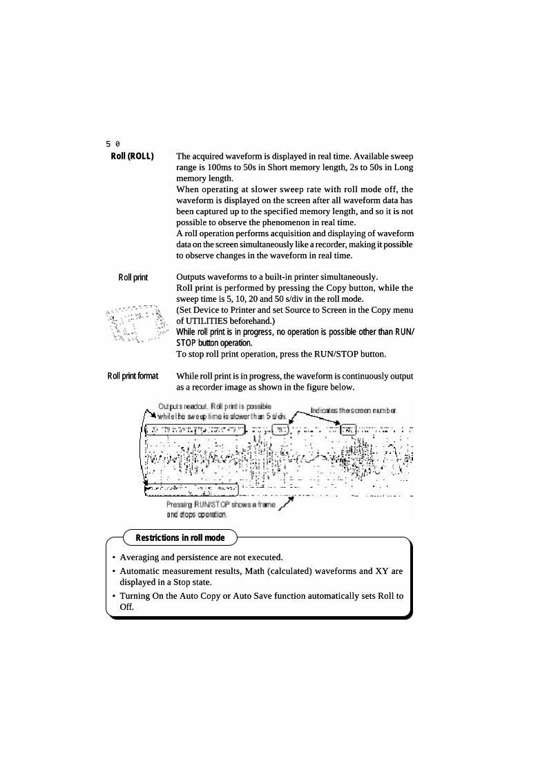
5050
The acquired waveform is displayed in real time. Available sweepThe acquired waveform is displayed in real time. Available sweeprange is 100ms to 50s in Short memory length, 2s to 50s in Longrange is 100ms to 50s in Short memory length, 2s to 50s in Longmemory length.memory length.When operating at slower sweep rate with roll mode off, theWhen operating at slower sweep rate with roll mode off, thewaveform is displayed on the screen after all waveform data haswaveform is displayed on the screen after all waveform data hasbeen captured up to the specified memory length, and so it is notbeen captured up to the specified memory length, and so it is notpossible to observe the phenomenon in real time.possible to observe the phenomenon in real time.A roll operation performs acquisition and displaying of waveformA roll operation performs acquisition and displaying of waveformdata on the screen simultaneously like a recorder, making it possibledata on the screen simultaneously like a recorder, making it possibleto observe changes in the waveform in real time.to observe changes in the waveform in real time.
Outputs waveforms to a built-in printer simultaneously.Outputs waveforms to a built-in printer simultaneously.Roll print is performed by pressing the Copy button, while theRoll print is performed by pressing the Copy button, while thesweep time is 5, 10, 20 and 50 s/div in the roll mode.sweep time is 5, 10, 20 and 50 s/div in the roll mode.(Set Device to Printer and set Source to Screen in the Copy menu(Set Device to Printer and set Source to Screen in the Copy menuof UTILITIES beforehand.)of UTILITIES beforehand.)While roll print is in progress, no operation is possible other than RUN/While roll print is in progress, no operation is possible other than RUN/STOP button operation.STOP button operation.To stop roll print operation, press the RUN/STOP button.To stop roll print operation, press the RUN/STOP button.
While roll print is in progress, the waveform is continuously outputWhile roll print is in progress, the waveform is continuously outputas a recorder image as shown in the figure below.as a recorder image as shown in the figure below.
Roll (ROLL)Roll (ROLL)
Roll printRoll print
Roll print formatRoll print format
Restrictions in roll modeRestrictions in roll mode
•• Averaging and persistence are not executed.Averaging and persistence are not executed.
•• Automatic measurement results, Math (calculated) waveforms and XY areAutomatic measurement results, Math (calculated) waveforms and XY aredisplayed in a Stop state.displayed in a Stop state.
•• Turning On the Auto Copy or Auto Save function automatically sets Roll toTurning On the Auto Copy or Auto Save function automatically sets Roll toOff.Off.

5151
Example of sweep modeExample of sweep modeTrigger'dTrigger'd
In this example, pressing the RUN button starts roll operation, and stops roll operationIn this example, pressing the RUN button starts roll operation, and stops roll operationwhen five rising edges are detected.when five rising edges are detected.
In this way, a waveform in the roll mode can be stopped under a specific triggerIn this way, a waveform in the roll mode can be stopped under a specific triggercondition.condition.
Sweep mode in Roll operationSweep mode in Roll operation
The setting of the sweep mode is performed by Sweep in the TRIGGERThe setting of the sweep mode is performed by Sweep in the TRIGGERmenu or with the AUTO/NORMAL/SGL button.menu or with the AUTO/NORMAL/SGL button.
The sweep mode setting is changedThe sweep mode setting is changeddepending on whether the roll mode isdepending on whether the roll mode isOFF or ON.OFF or ON.
Roll operationRoll operation
Roll is turned on Roll is turned on and "Roll" is displayedand "Roll" is displayedat the top rightat the top right..
In roll mode:In roll mode: Displays nothing.Displays nothing.
Roll mode is OFF:Roll mode is OFF: Displays sweepDisplays sweepmode. (Auto,mode. (Auto,Norm, SGL)Norm, SGL)
In the roll mode, the display variesIn the roll mode, the display variesdepending on the sweep mode.depending on the sweep mode.
Trigger'd:Trigger'd: Displays the triggerDisplays the triggerlevel.level.
Endless:Endless: Displays Endless.Displays Endless.
Roll mode is OFFRoll mode is OFF
AutoAuto
NormalNormal
SingleSingle
In roll modeIn roll mode
EndlessEndless
TriggerTrigger’’dd
1.1. Set Sweep to Trigger'd.Set Sweep to Trigger'd.The setting can also be changed byThe setting can also be changed bythe AUTO/NORM/SGL button.the AUTO/NORM/SGL button.
2.2. In the roll mode, Edge or Event canIn the roll mode, Edge or Event canbe selected as TrigType. TV cannotbe selected as TrigType. TV cannotbe selected.be selected.In this caseIn this case, Event trigger count is, Event trigger count isset to 5.set to 5.
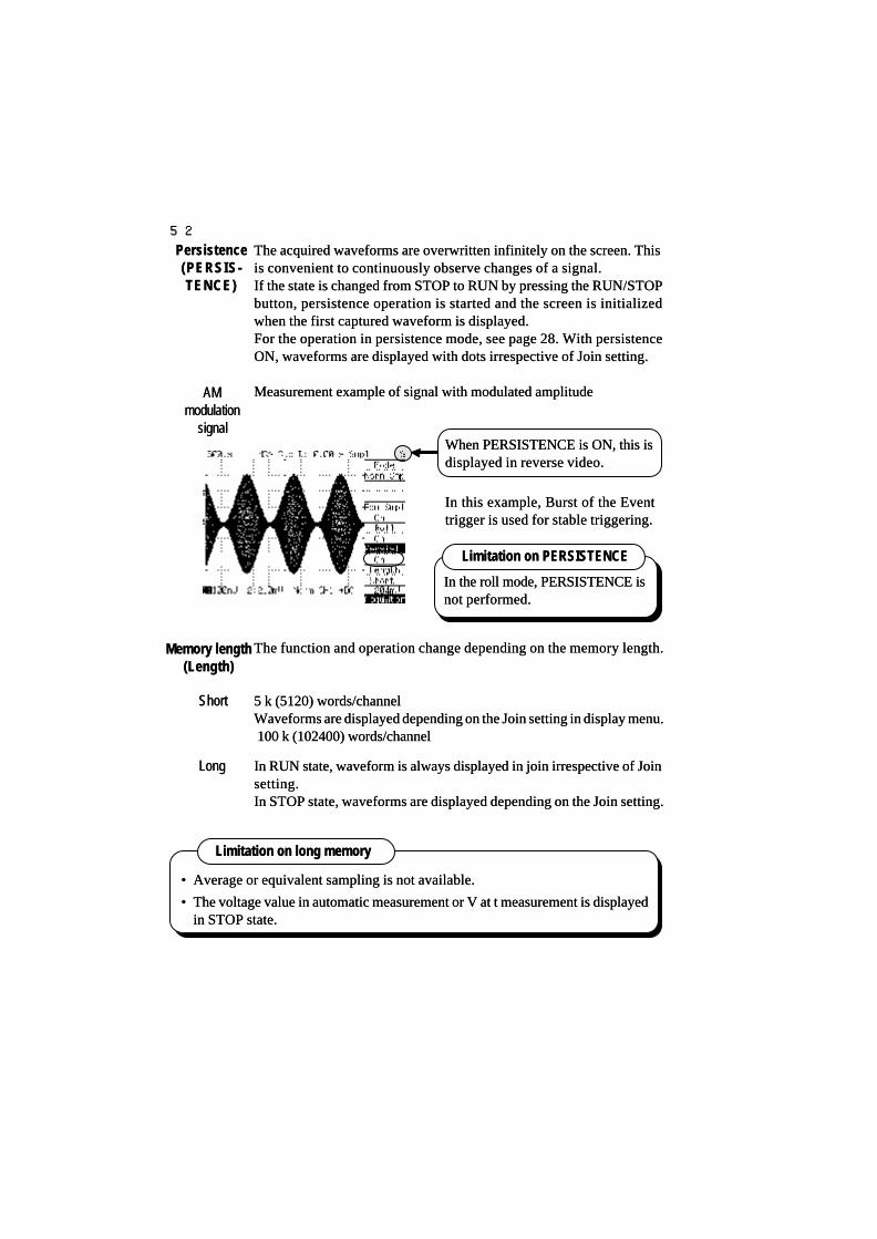
5252
The acquired waveforms are overwritten infinitely on the screen. ThisThe acquired waveforms are overwritten infinitely on the screen. Thisis convenient to continuously observe changes of a signal.is convenient to continuously observe changes of a signal.If the state is changed from STOP to RUN by pressing the RUN/STOPIf the state is changed from STOP to RUN by pressing the RUN/STOPbutton, persistence operation is started and the screen is initializedbutton, persistence operation is started and the screen is initializedwhen the first captured waveform is displayed.when the first captured waveform is displayed.For the operation in persistence mode, see page 28. With persistenceFor the operation in persistence mode, see page 28. With persistenceON, waveforms are displayed with dots irrespective of Join setting.ON, waveforms are displayed with dots irrespective of Join setting.
Measurement example of signal with modulated amplitudeMeasurement example of signal with modulated amplitude
The function and operation change depending on the memory length.The function and operation change depending on the memory length.
5 k (5120) words/channel5 k (5120) words/channelWaveforms are displayed depending on the Join setting in display menu.Waveforms are displayed depending on the Join setting in display menu. 100 k (102400) words/channel 100 k (102400) words/channel
In RUN state, waveform is always displayed in join irrespective of JoinIn RUN state, waveform is always displayed in join irrespective of Joinsetting.setting.In STOP state, waveforms are displayed depending on the Join setting.In STOP state, waveforms are displayed depending on the Join setting.
PersistencePersistence(PERSIS-(PERSIS-TENCE)TENCE)
AMAMmodulationmodulation
signalsignal
Memory lengthMemory length(Length)(Length)
ShortShort
LongLong
When PERSISTENCE is ON, this isWhen PERSISTENCE is ON, this isdisplayed in reverse video.displayed in reverse video.
In this example, Burst of the EventIn this example, Burst of the Eventtrigger is used for stable triggering.trigger is used for stable triggering.
Limitation on PERSISTENCELimitation on PERSISTENCE
In the roll mode, PERSISTENCE isIn the roll mode, PERSISTENCE isnot performed.not performed.
Limitation on long memoryLimitation on long memory
•• Average or equivalent sampling is not available.Average or equivalent sampling is not available.
•• The voltage value in automatic measurement or V at t measurement is displayedThe voltage value in automatic measurement or V at t measurement is displayedin STOP state.in STOP state.

5353
Cursor measurement in XY displayCursor measurement in XY display
Time related measurement is not available in XY display.Time related measurement is not available in XY display.
Measurement typeMeasurement type ContentContent Operable cursorOperable cursor
CH1 CH1 ∆∆VV Potential difference between H cursorsPotential difference between H cursors H-C1,H-C1, H-C2H-C2CH2 CH2 ∆∆VV Potential difference between V cursorsPotential difference between V cursors V-C1,V-C1, V-C2V-C2CH1&2 CH1&2 ∆∆VV Potential difference between H cursorsPotential difference between H cursors H-C1,H-C1, H-C2H-C2
Potential difference between V cursorsPotential difference between V cursors V-C1,V-C1, V-C2V-C2
Measurement example of CH1 & CH2 Measurement example of CH1 & CH2 ∆∆VV
←← Measurement item currently selectedMeasurement item currently selected
←← Cursor that can be operated by FUNCTION knobCursor that can be operated by FUNCTION knob
←← V measurement in vertical directionV measurement in vertical direction(measured by CH2 volts/div)(measured by CH2 volts/div)
V measurement in horizontal directionV measurement in horizontal direction(measured by CH1 volts/div)(measured by CH1 volts/div)
XY displayXY displayDisplays a waveform by expressing the horizontal direction (X) on theDisplays a waveform by expressing the horizontal direction (X) on theCH1 voltage axis and the vertical direction (Y) on the CH2 voltage axis.CH1 voltage axis and the vertical direction (Y) on the CH2 voltage axis.Allows observation of the phase difference of CH1 and CH2 signals, etc.Allows observation of the phase difference of CH1 and CH2 signals, etc.
Measurement example of 90° phase different sine wavesMeasurement example of 90° phase different sine waves
Limitation on XY displayLimitation on XY display
•• Calculated waveform display, reference waveform display or automatic measurementCalculated waveform display, reference waveform display or automatic measurementis not possible.is not possible.
•• Always displays with dots irrespective of Join setting.Always displays with dots irrespective of Join setting.
•• In the roll mode, waveforms are displayed in YT mode and if the state is changed fromIn the roll mode, waveforms are displayed in YT mode and if the state is changed fromRUN to STOP by pressing the RUN/STOP button, waveforms are displayed in XYRUN to STOP by pressing the RUN/STOP button, waveforms are displayed in XYmode.mode.
YT displayYT display XY displayXY display
Displays a nearly completeDisplays a nearly completeround Lissajous waveform.round Lissajous waveform.
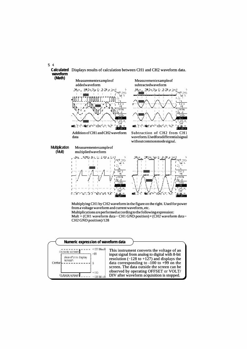
5454Displays results of calculation between CH1 and CH2 waveform data.Displays results of calculation between CH1 and CH2 waveform data.
Multiplying CH1 by CH2 waveform in the figure on the right. Used for powerMultiplying CH1 by CH2 waveform in the figure on the right. Used for powerfrom a voltage waveform and current waveform, etc.from a voltage waveform and current waveform, etc.Multiplications are performed according to the following expression:Multiplications are performed according to the following expression:Mult = (CH1 waveform data Mult = (CH1 waveform data −− CH1 GND position) CH1 GND position) ×× (CH2 waveform data (CH2 waveform data −−CH2 GND position)/128CH2 GND position)/128
MultiplicationMultiplication(Mult)(Mult)
This instrument converts the voltage of anThis instrument converts the voltage of aninput signal from analog to digital with 8-bitinput signal from analog to digital with 8-bitresolution (resolution (−−128 to +127) and displays the128 to +127) and displays thedata corresponding to -100 to +99 on thedata corresponding to -100 to +99 on thescreen. The data outside the screen can bescreen. The data outside the screen can beobserved by operating OFFSET or VOLT/observed by operating OFFSET or VOLT/DIV after waveform acquisition is stopped.DIV after waveform acquisition is stopped.
CalculatedCalculatedwaveformwaveform
(Math)(Math)
Measurement example ofMeasurement example ofmultiplied waveformmultiplied waveform
Numeric expression of waveform dataNumeric expression of waveform data
Addition of CH1 and CH2 waveformAddition of CH1 and CH2 waveformdatadata
Subtract ion of CH2 from CH1Subtract ion of CH2 from CH1waveform. Used for a differential signalwaveform. Used for a differential signalwithout common mode signal.without common mode signal.
Measurement example ofMeasurement example ofadded waveformadded waveform
Measurement example ofMeasurement example ofsubtracted waveformsubtracted waveform

5555
Automatic measurement (MEASURE)Automatic measurement (MEASURE)
Select Select ∆∆t for cursort for cursormeasurement.measurement.
Cursor that can beCursor that can beoperatedoperated
The + mark is displayedThe + mark is displayedas the level ofas the level ofmeasurement pointmeasurement pointselected in the menu.selected in the menu.←← −−PWPW →→←← ++PWPW →→
++ markmark
←←
MeasurementMeasurementareaarea
Specifies the measurement area between H cursors. If no H cursorsSpecifies the measurement area between H cursors. If no H cursorsare shown, the measurement area is the entire screen.are shown, the measurement area is the entire screen.
The H cursors are displayed by pressing the The H cursors are displayed by pressing the ∆∆V/V/∆∆t/t/∆∆V&V&∆∆t/V at t/t/V at t/OFF button and selecting OFF button and selecting ∆∆t of cursor measurement. (Likewise, the Ht of cursor measurement. (Likewise, the Hcursors can also be displayed by selecting cursors can also be displayed by selecting ∆∆V&V&∆∆t measurement.)t measurement.)
In this example, the root mean square (Vrms) and average (Vmean) ofIn this example, the root mean square (Vrms) and average (Vmean) ofthe CH1 waveform are measured.the CH1 waveform are measured.While another menu is displayed during cursor operation, etc.,While another menu is displayed during cursor operation, etc.,selecting Measure as Status in the DISPLAY menu displaysselecting Measure as Status in the DISPLAY menu displaysmeasurement results of A and B at the bottom of the screen.measurement results of A and B at the bottom of the screen.
With measurement that allows selection of measurement parameters,With measurement that allows selection of measurement parameters,if no reference waveform is displayedif no reference waveform is displayed, the level of measurement point is, the level of measurement point isindicated with a indicated with a ++ mark. mark.
MeasurementMeasurementpointpoint
displaydisplay
In this example, In this example, ++ pulse width ( pulse width (++PW) and PW) and −− pulse width ( pulse width (−−PW) andPW) andduty ratio (Duty) of CH1 waveform are measured.duty ratio (Duty) of CH1 waveform are measured.
H-C1cursorH-C1cursor H-C2cursorH-C2cursor
The cursors are moved byThe cursors are moved byturning the FUNCTION knob.turning the FUNCTION knob.The cursor to be operated isThe cursor to be operated isselected by pressing the C1/C2/selected by pressing the C1/C2/TCK buttons.TCK buttons.
In this example, the level ofIn this example, the level ofmeasurement of A is indicatedmeasurement of A is indicatedwith a + mark.with a + mark.

5656
Measures rise time of waveform in the specified area.Measures rise time of waveform in the specified area.
Measures fall time of waveform in the specified area.Measures fall time of waveform in the specified area.Set the following parameters.Set the following parameters.
Sets a reference waveform amplitude.Sets a reference waveform amplitude.If Top-Base is selected, Top and Base are found from a waveform dataIf Top-Base is selected, Top and Base are found from a waveform datahistogram and are set as 100%.histogram and are set as 100%.If P-P is selected, the span between Max. and Min. of the waveformIf P-P is selected, the span between Max. and Min. of the waveformdata in the specified area is set as 100%.data in the specified area is set as 100%.
The measurement end level is set at the Tr and the measurement startThe measurement end level is set at the Tr and the measurement startlevel is set at the Tf. The setting range is 11 to 90%.level is set at the Tf. The setting range is 11 to 90%.
The measurement start level is set at the Tr and the measurement endThe measurement start level is set at the Tr and the measurement endlevel is set at the Tf. The setting range is 10 to 89%.level is set at the Tf. The setting range is 10 to 89%.
Rise timeRise time( T r )( T r )
Fall time (Tf)Fall time (Tf)
1 0 0 %1 0 0 %
UpperUpper
LowerLower
Amplitude parameter (100%) setting and specification of measurement intervalAmplitude parameter (100%) setting and specification of measurement interval
When a waveform has an overshoot or undershoot as shown in the figure, theWhen a waveform has an overshoot or undershoot as shown in the figure, themeasured value varies depending on Top-Base or P-P selection.measured value varies depending on Top-Base or P-P selection.
If no area to be measured is specified, the rise (fall) time at the leftmost part ofIf no area to be measured is specified, the rise (fall) time at the leftmost part ofthe screen is measured.the screen is measured.
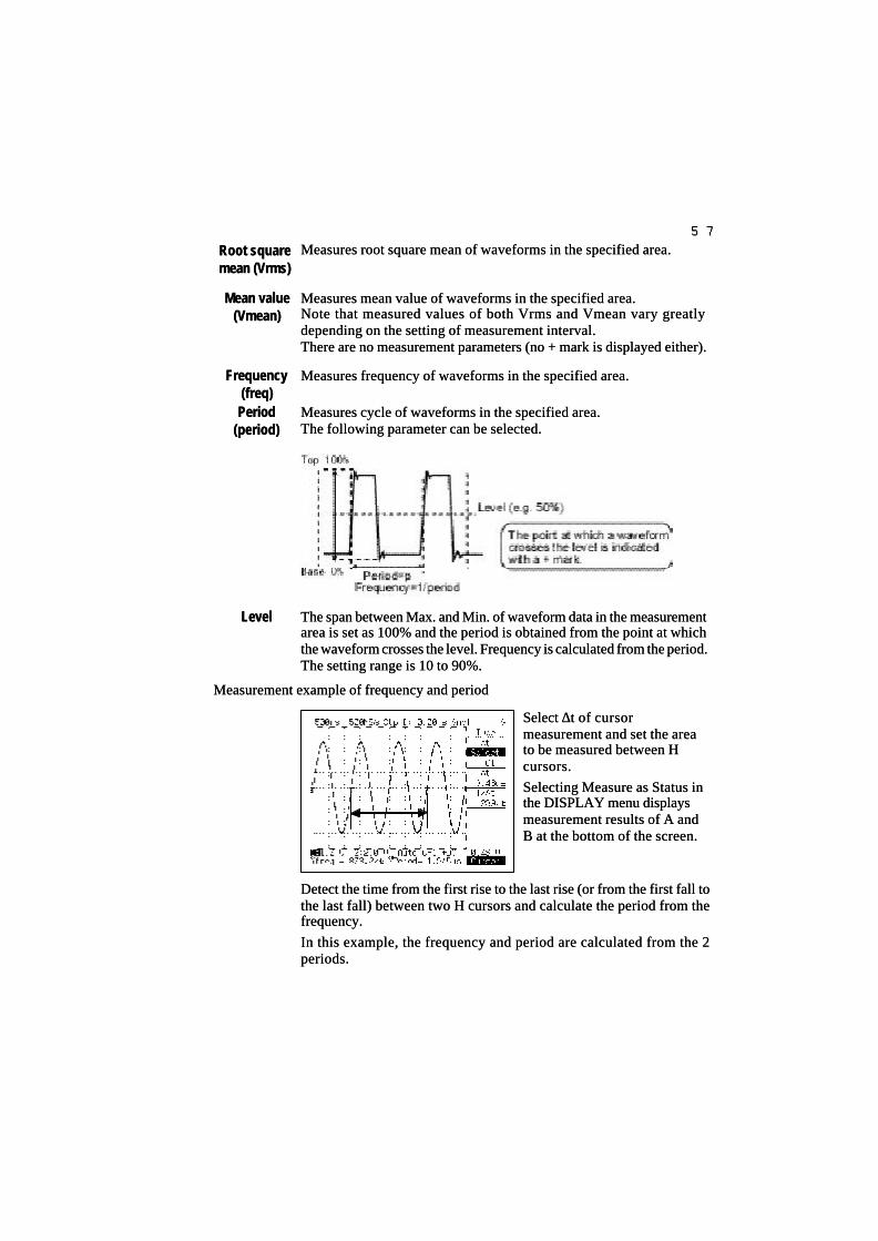
5757
Measures root square mean of waveforms in the specified area.Measures root square mean of waveforms in the specified area.
Measures mean value of waveforms in the specified area.Measures mean value of waveforms in the specified area.Note that measured values of both Vrms and Vmean vary greatlyNote that measured values of both Vrms and Vmean vary greatlydepending on the setting of measurement interval.depending on the setting of measurement interval.There are no measurement parameters (no + mark is displayed either).There are no measurement parameters (no + mark is displayed either).
Measures frequency of waveforms in the specified area.Measures frequency of waveforms in the specified area.
Measures cycle of waveforms in the specified area.Measures cycle of waveforms in the specified area.The following parameter can be selected.The following parameter can be selected.
The span between Max. and Min. of waveform data in the measurementThe span between Max. and Min. of waveform data in the measurementarea is set as 100% and the period is obtained from the point at whicharea is set as 100% and the period is obtained from the point at whichthe waveform crosses the level. Frequency is calculated from the period.the waveform crosses the level. Frequency is calculated from the period.The setting range is 10 to 90%.The setting range is 10 to 90%.
Measurement example of frequency and periodMeasurement example of frequency and period
Select Select ∆∆t of cursort of cursormeasurement and set the areameasurement and set the areato be measured between Hto be measured between Hcursors.cursors.
Selecting Measure as Status inSelecting Measure as Status inthe DISPLAY menu displaysthe DISPLAY menu displaysmeasurement results of A andmeasurement results of A andB at the bottom of the screen.B at the bottom of the screen.
Root squareRoot squaremean (Vrms)mean (Vrms)
FrequencyFrequency(freq)(freq)
PeriodPeriod(period)(period)
LevelLevel
Detect the time from the first rise to the last rise (or from the first fall toDetect the time from the first rise to the last rise (or from the first fall tothe last fall) between two H cursors and calculate the period from thethe last fall) between two H cursors and calculate the period from thefrequency.frequency.
In this example, the frequency and period are calculated from the 2In this example, the frequency and period are calculated from the 2periods.periods.
Mean valueMean value(Vmean)(Vmean)

5858+Pulse width+Pulse width
(+PW)(+PW)−−Pulse widthPulse width
((−−PW)PW)
Duty ratioDuty ratio(Duty)(Duty)
LevelLevel
Measures + pulse width of waveform in the specified area.Measures + pulse width of waveform in the specified area.
Measures Measures −− pulse width of waveform in the specified area. pulse width of waveform in the specified area.
Measures the ratio of waveform period to + pulse width in the specifiedMeasures the ratio of waveform period to + pulse width in the specifiedarea.area.The following parameter can be selected:The following parameter can be selected:
Top and Base are set from Max. and Min. of waveform data in theTop and Base are set from Max. and Min. of waveform data in thespecified area, and it is set as 100% and specified area, and it is set as 100% and ±± pulse width and period are pulse width and period arecalculated from the point at which the waveform data crosses thecalculated from the point at which the waveform data crosses thevalue specified by Level.value specified by Level.
Measures maximum value of waveform in Measures maximum value of waveform in the specified areathe specified area..Maximum valueMaximum value((++PEAK)PEAK)
Minimum valueMinimum value((−−PEAK)PEAK)
Measures minimum value of waveform in Measures minimum value of waveform in the specified areathe specified area..
Difference betweenDifference betweenmaximum value andmaximum value and
minimum valueminimum value(P-P)(P-P)
Measures difference between maximum value and minimum valueMeasures difference between maximum value and minimum valueof waveform in of waveform in the specified area.the specified area.There is no measurement parameter (no There is no measurement parameter (no ++ mark either) mark either)
Measuring + pulse width, Measuring + pulse width, −− pulse width and duty ratio pulse width and duty ratio
If there are plural pulses in theIf there are plural pulses in thespecified area as shown in the figure,specified area as shown in the figure,the leftmost pulse is measured.the leftmost pulse is measured.

5959
Measures time difference between rising (falling) edge of CH1 waveformMeasures time difference between rising (falling) edge of CH1 waveformand rising (falling) edge of CH2 waveform in the specified area.and rising (falling) edge of CH2 waveform in the specified area.Set the following parameters.Set the following parameters.
Sets the level at which the waveform data crosses the level as referenceSets the level at which the waveform data crosses the level as referenceregarding the span between maximum and minimum values of CH1regarding the span between maximum and minimum values of CH1waveform as 100% in the specified area .waveform as 100% in the specified area .The setting range is 10 to 90%.The setting range is 10 to 90%.
Selects edge of CH1 waveform.Selects edge of CH1 waveform.Rise: Uses rising edge.Rise: Uses rising edge.Fall: Uses falling edge.Fall: Uses falling edge.The first specified edge in the specified area becomes the skewThe first specified edge in the specified area becomes the skewmeasurement start or end point.measurement start or end point.
Sets the level of CH2 waveform in the same way as for the CH1 level.Sets the level of CH2 waveform in the same way as for the CH1 level.
Selects the edge of CH2 waveform in the same way as for the CH1 edge.Selects the edge of CH2 waveform in the same way as for the CH1 edge.
Skew measurement exampleSkew measurement example
In this example, the time from the CH1 waveform rise to the CH2 waveformIn this example, the time from the CH1 waveform rise to the CH2 waveformfall between two H cursors is measured.fall between two H cursors is measured.
SkewSkew(SKEW)(SKEW)
CH1 LevelCH1 Level
CH1 EdgeCH1 Edge
CH2 LevelCH2 Level
CH2 EdgeCH2 Edge
Select Parameter in theSelect Parameter in theMeasure menu and displayMeasure menu and displaythe Skew parameter menu.the Skew parameter menu.
Select Edge or Level.Select Edge or Level.
Indicates that this is theIndicates that this is theSkew parameter menu.Skew parameter menu.

6060
Save/recall/delete (SAVE/RECALL/DELETE)Save/recall/delete (SAVE/RECALL/DELETE)
Also see Section 1 "SAVE/RECALL menu" (pages 34 to 37).Also see Section 1 "SAVE/RECALL menu" (pages 34 to 37).
Selecting DEVICE in the SAVE/RECALL menu shows the remainingSelecting DEVICE in the SAVE/RECALL menu shows the remainingcapacity of a medium.capacity of a medium.
CapacityCapacitydisplaydisplay
While Floppy or ATA Card is highlighted, the remainingWhile Floppy or ATA Card is highlighted, the remainingcapacity of the medium is displayed at the bottom ofcapacity of the medium is displayed at the bottom ofthe screen.the screen.
Saving panel setting to ATA cardSaving panel setting to ATA card
1.1. Display SAVE/RECALL menu.Display SAVE/RECALL menu.
2.2. Through [FUNCTION operation], set Device to ATA card.Through [FUNCTION operation], set Device to ATA card.
3.3. Through [FUNCTION operation], set Type to Setup (panel setting).Through [FUNCTION operation], set Type to Setup (panel setting).
4.4. Set Function to Save with [Function operation].Set Function to Save with [Function operation].
5.5. Specify the File No. (e.g. specify "1").Specify the File No. (e.g. specify "1").
You can set the file No. in steps of 20 when Course is set.You can set the file No. in steps of 20 when Course is set.
6.6. After specifying the File No., press the FUNCTION knob. TheAfter specifying the File No., press the FUNCTION knob. Themessage "Press FUNCTION to save" appears. Press the knobmessage "Press FUNCTION to save" appears. Press the knobagain to execute SAVE. If the specified file already exists, theagain to execute SAVE. If the specified file already exists, themessage "Press FUNCTION again to overwrite" appears.message "Press FUNCTION again to overwrite" appears.
Recalling panel setting from ATA cardRecalling panel setting from ATA card
1 to 3. Perform the same setting as that for saving.1 to 3. Perform the same setting as that for saving.4. Through [FUNCTION operation], set Function to Recall (recall).4. Through [FUNCTION operation], set Function to Recall (recall).
5.5. Specify the File No. (e.g. specify "1"). Only existing file Nos. areSpecify the File No. (e.g. specify "1"). Only existing file Nos. areselected and displayed during a recall. If Coarse is selected, theselected and displayed during a recall. If Coarse is selected, theexisting files are selected and displayed at every 20 steps. If noexisting files are selected and displayed at every 20 steps. If nofiles are found, **** is displayed. When recalling the panel settingfiles are found, **** is displayed. When recalling the panel settingfrom an ATA card, selected file Nos. are recalled sequentially.from an ATA card, selected file Nos. are recalled sequentially.
6. Pressing the FUNCTION knob stops the recall.6. Pressing the FUNCTION knob stops the recall.

6161
Saving waveform data to ATA cardSaving waveform data to ATA card
1.1. Display SAVE/RECALL menu.Display SAVE/RECALL menu.2.2. Through [FUNCTION operation], set Device to ATA card.Through [FUNCTION operation], set Device to ATA card.3.3. Through [FUNCTION operation], set Type to WaveformThrough [FUNCTION operation], set Type to Waveform
(waveform).(waveform).4.4. Through [FUNCTION operation], select Binary or ASCII as Style.Through [FUNCTION operation], select Binary or ASCII as Style.4 to 6. Perform the same setting as for saving of the panel setting.4 to 6. Perform the same setting as for saving of the panel setting.
Recalling waveform data from ATA cardRecalling waveform data from ATA card1.1. Display SAVE/RECALL menu.Display SAVE/RECALL menu.2.2. Through [FUNCTION operation], set Device to ATA card.Through [FUNCTION operation], set Device to ATA card.3.3. Through [FUNCTION operation], set Type to WaveformThrough [FUNCTION operation], set Type to Waveform
(waveform).(waveform).4.4. Through [FUNCTION operation], select Binary as Style.Through [FUNCTION operation], select Binary as Style.4 to 6. Perform the same operation as for recalling of the panel4 to 6. Perform the same operation as for recalling of the panelsetting.setting.
Display the SAVE/RECALL menu and through [FUNCTION operation]Display the SAVE/RECALL menu and through [FUNCTION operation]set Function to Delete and specify the File No. and execute it.set Function to Delete and specify the File No. and execute it.If no file exists in the device, File. No. is displayed as ****.If no file exists in the device, File. No. is displayed as ****.
Deleting fileDeleting file
Waveform data saved in ASCII format cannot be recalled by this instrument.Waveform data saved in ASCII format cannot be recalled by this instrument.
In a file saved in ASCII format, CH1, CH2 waveform data and auxiliary informationIn a file saved in ASCII format, CH1, CH2 waveform data and auxiliary informationare stored in CSV format. Therefore, simply clicking on them from a PC can startare stored in CSV format. Therefore, simply clicking on them from a PC can startExcel or Lotus and edit them. (CSV: Comma Separated Value)Excel or Lotus and edit them. (CSV: Comma Separated Value)
Waveform data saved in ASCII format is converted to the voltage by the followingWaveform data saved in ASCII format is converted to the voltage by the followingequation.equation.(Calculation) = (Waveform data / 25 (Calculation) = (Waveform data / 25 -- OFFSET) OFFSET) ×× volts per division [V/div]volts per division [V/div]
When waveform is Off, no data is displayed.When waveform is Off, no data is displayed.
Editing waveform data saved in ASCII format by ExcelEditing waveform data saved in ASCII format by Excel
Waveform acquisition timeWaveform acquisition timeTime/DIVTime/DIV
CH1 waveform On/OffCH1 waveform On/OffCH1 Volts/DIVCH1 Volts/DIV
CH1 OffsetCH1 OffsetCH1 waveform dataCH1 waveform data
2022-3-4 6:512022-3-4 6:51200 ns/DIV200 ns/DIVONON2.0 V/DIV2.0 V/DIV1.96 DIV1.96 DIV828283838383
DelayDelayCH2 waveform On/OffCH2 waveform On/OffCH2 Volts/DIVCH2 Volts/DIVCH2 OffsetCH2 OffsetCH2 waveform dataCH2 waveform data
0.00 s0.00 sONON2.0 V/DIV2.0 V/DIV−−3.00 DIV3.00 DIV−−7474−−7474−−7373
… …

6262
Copy (COPY)Copy (COPY)Also see Section 1 "Copy function" (page 24), "Built-in printer" (page 25) andAlso see Section 1 "Copy function" (page 24), "Built-in printer" (page 25) and"UTILITIES menu" (page 38) together."UTILITIES menu" (page 38) together.Outputs a hardcopy of the screen and panel setting to the built-inOutputs a hardcopy of the screen and panel setting to the built-inprinter, floppy disk, ATA card and Centronics port.printer, floppy disk, ATA card and Centronics port.
If the device is Floppy or ATA Card, select the function Copy/Delete.If the device is Floppy or ATA Card, select the function Copy/Delete.To execute the function, specify File No.To execute the function, specify File No.\\ TIFF:TIFF: Saves/deletes TIFF format screen or panel setting.Saves/deletes TIFF format screen or panel setting.
The file extension is TIF.The file extension is TIF.BMP:BMP: Saves/deletes BMP format screen or panel setting.Saves/deletes BMP format screen or panel setting.
The file extension is BMP.The file extension is BMP.
Executing a copy creates the above directory under the root of theExecuting a copy creates the above directory under the root of thespecified device and saves the file with specified file No.specified device and saves the file with specified file No.Executing Delete detects the existing files from each directory under theExecuting Delete detects the existing files from each directory under theroot of the specified device and deletes specified file No.root of the specified device and deletes specified file No.
SourceSource(SOURCE)(SOURCE)
DeviceDevice(DEVICE)(DEVICE)
Output typeOutput type(TYPE)(TYPE)
FunctionFunctionsettingsetting

6363
Copy to floppy diskCopy to floppy disk
1.1. Select Copy in the UTILITIES menu and display the copy menu.Select Copy in the UTILITIES menu and display the copy menu.
2.2. Through [FUNCTION operation], set Device to Floppy.Through [FUNCTION operation], set Device to Floppy.
3.3. Through [FUNCTION operation], set Type to TIFF (or BMP).Through [FUNCTION operation], set Type to TIFF (or BMP).
4.4. Through [FUNCTION operation], set Function to Copy.Through [FUNCTION operation], set Function to Copy.
5.5. Through [FUNCTION operation], set File No. at every stepThrough [FUNCTION operation], set File No. at every step(e.g."1"). If Coarse is selected, File No.can be set at every 20(e.g."1"). If Coarse is selected, File No.can be set at every 20steps.steps.
6.6. After file No. is selected, press the FUNCTION knob to confirmAfter file No. is selected, press the FUNCTION knob to confirmthe setting. Every depressing of the Copy button executes a copythe setting. Every depressing of the Copy button executes a copyand increments file No. by 1 when the copy is completed.and increments file No. by 1 when the copy is completed.
Copy to ATA cardCopy to ATA card
1.1. Select Copy in the UTILITIES menu and display the copy menu.Select Copy in the UTILITIES menu and display the copy menu.
2.2. Through [FUNCTION operation], set Device to ATA Card.Through [FUNCTION operation], set Device to ATA Card.
3 to 6. Perform the same setting as for floppy.3 to 6. Perform the same setting as for floppy.If Coarse is selected for ATA card, File No. can be set at every 20If Coarse is selected for ATA card, File No. can be set at every 20steps.steps.
Selecting Delete in the Function menu allows a specified file to beSelecting Delete in the Function menu allows a specified file to bedeleted.deleted.
Auto Copy makes a copy to a specified device every new waveform isAuto Copy makes a copy to a specified device every new waveform isacquired automatically.acquired automatically.Turning On Auto Copy stops waveform acquisition and pressing theTurning On Auto Copy stops waveform acquisition and pressing theRUN/STOP button restarts waveform acquisition.RUN/STOP button restarts waveform acquisition.No operation other than RUN/STOP button operation is acceptedNo operation other than RUN/STOP button operation is acceptedwhile Auto Copy is in progress. While operation is stopped, the Autowhile Auto Copy is in progress. While operation is stopped, the AutoCopy setting can be turned Off.Copy setting can be turned Off.
Deleting fileDeleting file
SettingSettingAuto CopyAuto Copy
Number of files and capacityNumber of files and capacity
A floppy disk can save up to 200 TIFF or BMP files.A floppy disk can save up to 200 TIFF or BMP files.
An ATA card can save up to 9999 TIFF or BMP files.An ATA card can save up to 9999 TIFF or BMP files.
Each file requires a capacity of 10Kbytes, but the number of files that can beEach file requires a capacity of 10Kbytes, but the number of files that can besaved depends on the remaining capacity of a floppy disk or ATA card.saved depends on the remaining capacity of a floppy disk or ATA card.

6464
Appendix 1Appendix 1
Table 1 Sampling Period and On-Screen Data Count for Short MemoryTable 1 Sampling Period and On-Screen Data Count for Short Memory
Time axis (range) Time axis (range) Sampling rateSampling rate Sampling periodSampling period On-screen data countOn-screen data count50 s/div50 s/div 10 S/s10 S/s 100 ms100 ms 5,000 words5,000 words20 s/div20 s/div 25 S/s 25 S/s 40 ms40 ms 5,000 words5,000 words10 s/div10 s/div 50 S/s 50 S/s 20 ms20 ms 5,000 words5,000 words5 s/div5 s/div 100 S/s 100 S/s 10 ms10 ms 5,000 words5,000 words2 s/div2 s/div 250 S/s 250 S/s 4 ms4 ms 5,000 words5,000 words1 s/div1 s/div 500 S/s 500 S/s 2 ms2 ms 5,000 words5,000 words
500 ms/div500 ms/div 1 kS/s 1 kS/s 1 ms1 ms 5,000 words5,000 words200 ms/div200 ms/div 2.5 kS/s 2.5 kS/s 400 400 µµss 5,000 words5,000 words100 ms/div100 ms/div 5 kS/s 5 kS/s 200 200 µµss 5,000 words5,000 words50 ms/div50 ms/div 10 kS/s 10 kS/s 100 100 µµss 5,000 words5,000 words20 ms/div20 ms/div 25 kS/s 25 kS/s 40 40 µµss 5,000 words5,000 words10 ms/div10 ms/div 50 kS/s 50 kS/s 20 20 µµss 5,000 words5,000 words5 ms/div5 ms/div 100 kS/s 100 kS/s 10 10 µµss 5,000 words5,000 words2 ms/div2 ms/div 250 kS/s 250 kS/s 4 4 µµss 5,000 words5,000 words1 ms/div1 ms/div 500 kS/s 500 kS/s 2 2 µµss 5,000 words5,000 words
500 500 µµs/divs/div 1 MS/s1 MS/s 1 1 µµss 5,000 words5,000 words
200 200 µµs/divs/div 2.5 MS/s2.5 MS/s 400 ns400 ns 5,000 words5,000 words
100 100 µµs/divs/div 5 MS/s5 MS/s 200 ns200 ns 5,000 words5,000 words
50 50 µµs/divs/div 10 MS/s10 MS/s 100 ns100 ns 5,000 words5,000 words
20 20 µµs/divs/div 25 MS/s25 MS/s 40 ns40 ns 5,000 words5,000 words
10 10 µµs/divs/div 50 MS/s50 MS/s 20 ns20 ns 5,000 words5,000 words
5 5 µµs/divs/div 100 MS/s100 MS/s 10 ns10 ns 5,000 words5,000 words
2 2 µµs/divs/div 250 MS/s250 MS/s 4 ns4 ns 5,000 words5,000 words
1 1 µµs/divs/div 500 MS/s500 MS/s 2 ns2 ns 5,000 words5,000 words500 ns/div500 ns/div 500 MS/s500 MS/s ( 1 GS/s) ( 1 GS/s) 2 ns2 ns ( 1 ns) ( 1 ns) 2,500 words2,500 words (5,000 words)(5,000 words)200 ns/div200 ns/div 500 MS/s500 MS/s (2.5 GS/s) (2.5 GS/s) 2 ns2 ns (400 ps) (400 ps) 1,000 words1,000 words (5,000 words)(5,000 words)100 ns/div100 ns/div 500 MS/s500 MS/s ( 5 GS/s) ( 5 GS/s) 2 ns2 ns (200 ps) (200 ps) 500 words500 words (5,000 words)(5,000 words)50 ns/div50 ns/div 500 MS/s500 MS/s ( 10 GS/s) ( 10 GS/s) 2 ns2 ns (100 ps) (100 ps) 250 words250 words (5,000 words)(5,000 words)20 ns/div20 ns/div 500 MS/s500 MS/s ( 25 GS/s) ( 25 GS/s) 2 ns2 ns ( 40 ps) ( 40 ps) 100 words100 words (5,000 words)(5,000 words)10 ns/div10 ns/div 500 MS/s500 MS/s ( 25 GS/s) ( 25 GS/s) 2 ns 2 ns ( 40 ps) ( 40 ps) 50 words50 words (2,500 words)(2,500 words)
5ns/div5ns/div 500 MS/s500 MS/s ( 25 GS/s) ( 25 GS/s) 2 ns2 ns ( 40 ps) ( 40 ps) 25 words25 words (1,250 words)(1,250 words)
Note 1.Note 1. Figures in parentheses apply when equivalent sampling is performed.Figures in parentheses apply when equivalent sampling is performed.
Note 2.Note 2. The remaining data after subtracting the on-screen data count from memory lengthThe remaining data after subtracting the on-screen data count from memory length(5 kwordss) is not displayed on the screen, but is stored into internal memory as the data(5 kwordss) is not displayed on the screen, but is stored into internal memory as the datapreceding the left end of the screen.preceding the left end of the screen.

6565
Appendix 2Appendix 2
Table 2 Sampling Rate and Display Memory Length for Long MemoryTable 2 Sampling Rate and Display Memory Length for Long Memory
Time axis (range) Time axis (range) Sampling rateSampling rate Sampling periodSampling period On-screen data countOn-screen data count50 s/div50 s/div 200 S/s 200 S/s 5 ms 5 ms 100,000 words100,000 words 20 s/div 20 s/div 500 S/s 500 S/s 2 ms 2 ms 100,000 words100,000 words10 s/div10 s/div 1 kS/s 1 kS/s 1 ms 1 ms 100,000 words100,000 words5 s/div5 s/div 2 kS/s 2 kS/s 500 500 µµss 100,000 words100,000 words
2 s/div2 s/div 5 kS/s 5 kS/s 200 200 µµss 100,000 words100,000 words
1 s/div1 s/div 10 kS/s 10 kS/s 100 100 µµss 100,000 words100,000 words
500 ms/div500 ms/div 20 kS/s 20 kS/s 50 50 µµss 100,000 words100,000 words
200 ms/div200 ms/div 50 kS/s 50 kS/s 20 20 µµss 100,000 words100,000 words
100 ms/div100 ms/div 100 kS/s 100 kS/s 10 10 µµss 100,000 words100,000 words
50 ms/div50 ms/div 200 kS/s 200 kS/s 5 5 µµss 100,000 words100,000 words
20 ms/div20 ms/div 500 kS/s 500 kS/s 2 2 µµss 100,000 words100,000 words
10 ms/div10 ms/div 1 MS/s 1 MS/s 1 1 µµss 100,000 words100,000 words5 ms/div5 ms/div 2 MS/s 2 MS/s 500 ns 500 ns 100,000 words100,000 words2 ms/div2 ms/div 5 MS/s 5 MS/s 200 ns 200 ns 100,000 words100,000 words1 ms/div1 ms/div 10 MS/s 10 MS/s 100 ns 100 ns 100,000 words100,000 words
500 500 µµs/divs/div 20 MS/s 20 MS/s 50 ns 50 ns 100,000 words100,000 words
200 200 µµs/divs/div 50 MS/s 50 MS/s 20 ns 20 ns 100,000 words100,000 words
100 100 µµs/divs/div 100 MS/s 100 MS/s 10 ns 10 ns 100,000 words100,000 words
50 50 µµs/divs/div 100 MS/s 100 MS/s 10 ns 10 ns 50,000 words50,000 words
20 20 µµs/divs/div 500 MS/s 500 MS/s 2 ns 2 ns 100,000 words100,000 words
10 10 µµs/divs/div 500 MS/s 500 MS/s 2 ns 2 ns 50,000 words50,000 words
5 5 µµs/divs/div 500 MS/s 500 MS/s 2 ns 2 ns 25,000 words 25,000 words
2 2 µµs/divs/div 500 MS/s 500 MS/s 2 ns 2 ns 10,000 words10,000 words
1 1 µµs/divs/div 500 MS/s 500 MS/s 2 ns 2 ns 5,000 words5,000 words500 ns/div500 ns/div 500 MS/s500 MS/s 2 ns 2 ns 2500 words2500 words200 ns/div200 ns/div 500 MS/s 500 MS/s 2 ns 2 ns 1,000 words1,000 words100 ns/div100 ns/div 500 MS/s 500 MS/s 2 ns 2 ns 500 words500 words50 ns/div50 ns/div 500 MS/s 500 MS/s 2 ns 2 ns 250 words250 words20 ns/div20 ns/div 500 MS/s 500 MS/s 2 ns 2 ns 100 words100 words10 ns/div10 ns/div 500 MS/s500 MS/s 2 ns2 ns 50 words50 words5 ns/div5 ns/div 500 MS/s500 MS/s 2 ns2 ns 25 words25 words
Note 1.Note 1. Equivalent sampling is not available when long memory is selected.Equivalent sampling is not available when long memory is selected.Note 2.Note 2. The remaining data after subtracting the on-screen data count from memory lengthThe remaining data after subtracting the on-screen data count from memory length
(100 kwordss) is the same as for short memory.(100 kwordss) is the same as for short memory.
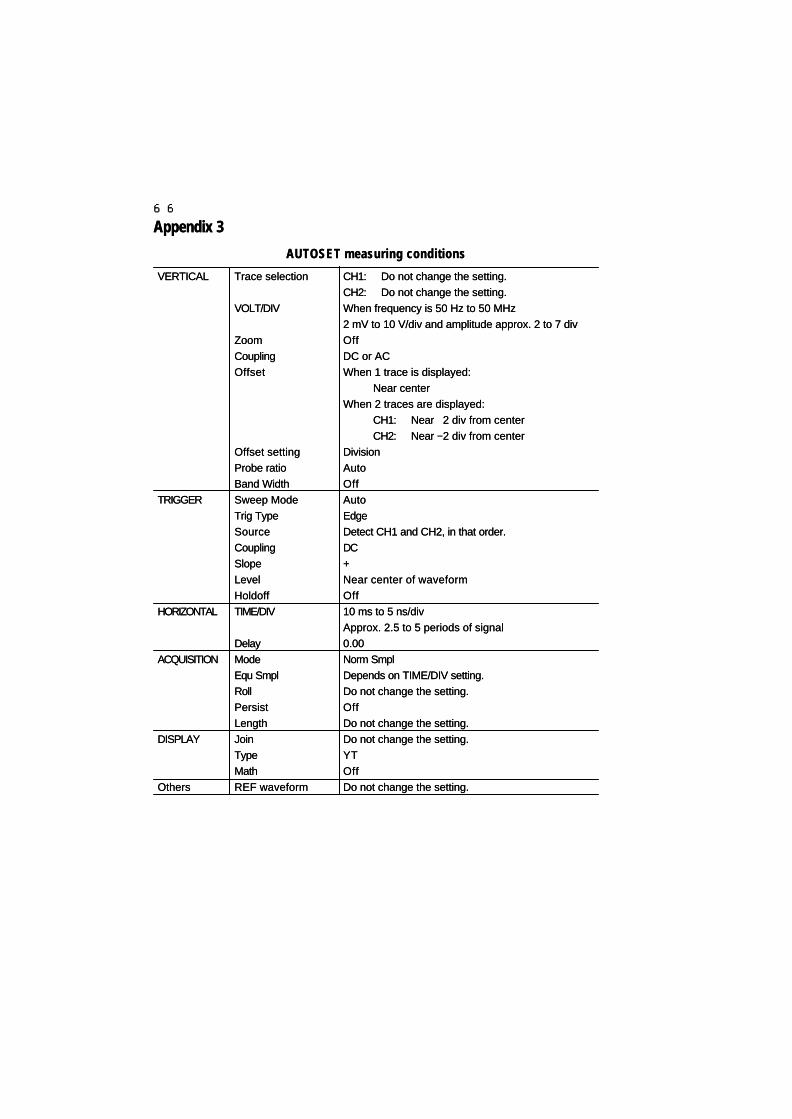
6666
Appendix 3Appendix 3
AUTOSET measuring conditionsAUTOSET measuring conditions
VERTICALVERTICAL
TRIGGERTRIGGER
HORIZONTALHORIZONTAL
ACQUISITIONACQUISITION
DISPLAYDISPLAY
OthersOthers
Trace selectionTrace selection
VOLT/DIVVOLT/DIV
ZoomZoomCouplingCouplingOffsetOffset
Offset settingOffset settingProbe ratioProbe ratioBand WidthBand WidthSweep ModeSweep ModeTrig TypeTrig TypeSourceSourceCouplingCouplingSlopeSlopeLevelLevelHoldoffHoldoffTIME/DIVTIME/DIV
DelayDelayModeModeEqu SmplEqu SmplRollRollPersistPersistLengthLengthJoinJoinTypeTypeMathMathREF waveformREF waveform
CH1:CH1: Do not change the setting.Do not change the setting.CH2:CH2: Do not change the setting.Do not change the setting.When frequency is 50 Hz to 50 MHzWhen frequency is 50 Hz to 50 MHz2 mV to 10 V/div and amplitude approx. 2 to 7 div2 mV to 10 V/div and amplitude approx. 2 to 7 divOffOffDC or ACDC or ACWhen 1 trace is displayed:When 1 trace is displayed:
Near centerNear centerWhen 2 traces are displayed:When 2 traces are displayed:
CH1:CH1: Near Near ++2 div from center2 div from centerCH2:CH2: Near Near −−2 div from center2 div from center
DivisionDivisionAutoAutoOffOffAutoAutoEdgeEdgeDetect CH1 and CH2, in that order.Detect CH1 and CH2, in that order.DCDC++Near center of waveformNear center of waveformOffOff10 ms to 5 ns/div10 ms to 5 ns/divApprox. 2.5 to 5 periods of signalApprox. 2.5 to 5 periods of signal0.000.00Norm SmplNorm SmplDepends on TIME/DIV setting.Depends on TIME/DIV setting.Do not change the setting.Do not change the setting.OffOffDo not change the setting.Do not change the setting.Do not change the setting.Do not change the setting.YTYTOffOffDo not change the setting.Do not change the setting.

6767
Appendix 4Appendix 4
<Panel setting> to be saved<Panel setting> to be saved
All ACQUISITION menu itemsAll ACQUISITION menu itemsAll DISPLAY menu items except Display and StatusAll DISPLAY menu items except Display and StatusAll MEASURE menu itemsAll MEASURE menu itemsAll CH menu itemsAll CH menu itemsAll TRIG menu itemsAll TRIG menu items
Detailed menu treesDetailed menu trees

6868
MemoMemo

6969
Section 3Section 3 Daily CareDaily Care

7070
a. Maintenance methoda. Maintenance method
•• CleaningCleaning
Disconnect the power cord before cleaning to prevent electric shock. Wipe off theDisconnect the power cord before cleaning to prevent electric shock. Wipe off thedirt on the surface of the instrument and cover with a small volume of water or milddirt on the surface of the instrument and cover with a small volume of water or milddetergent. Use only recommended cleaning solvents; failure to comply could resultdetergent. Use only recommended cleaning solvents; failure to comply could resultin discoloration or damage.in discoloration or damage.
•• Usable solvents or detergents:Usable solvents or detergents: Water, detergent (diluted)Water, detergent (diluted)
•• Prohibited:Prohibited: Alcohol, gasoline, acetone, lacquer, ether,Alcohol, gasoline, acetone, lacquer, ether,thinner, and cleansers containing ketonesthinner, and cleansers containing ketones
•• Cleaning displayCleaning display
Remove dirt in the following manner:Remove dirt in the following manner:
•• Wipe off ordinary dirt with a soft cloth.Wipe off ordinary dirt with a soft cloth.
•• Wipe off stubborn dirt with a cloth dampened with mild detergent.Wipe off stubborn dirt with a cloth dampened with mild detergent.
b. Automatic self-calibrationb. Automatic self-calibration
Automatically self-calibrates sensitivity, offset, and trigger level.Automatically self-calibrates sensitivity, offset, and trigger level.
Procedure of automatic calibrationProcedure of automatic calibration
1.1. Through [FUNCTION control], set the UTILITIES menu to Config.Through [FUNCTION control], set the UTILITIES menu to Config.
2.2. Pressing FUNCTION knob shows the Config menu.Pressing FUNCTION knob shows the Config menu.
3.3. Through [FUNCTION control], set the Config menu to Self Cal.Through [FUNCTION control], set the Config menu to Self Cal.
4.4. Pressing FUNCTION knob twice shows “Pressing FUNCTION again startsPressing FUNCTION knob twice shows “Pressing FUNCTION again startscalibration” and pressing FUNCTION knob again in this condition startscalibration” and pressing FUNCTION knob again in this condition startscalibration .calibration .
While automatic calibration is in progress, no panel operation is possible. CalibrationWhile automatic calibration is in progress, no panel operation is possible. Calibrationtakes approx. 4 minutes.takes approx. 4 minutes.
When calibration ends normally, “Calibration has ended” is displayed.When calibration ends normally, “Calibration has ended” is displayed.
If “Failed to calibrate” is displayed, try again automatic calibration several times and ifIf “Failed to calibrate” is displayed, try again automatic calibration several times and ifthe same message still appears, contact our service representative.the same message still appears, contact our service representative.
c. Recommended interval of calibrationc. Recommended interval of calibration
Carry out calibration every 2000 hours if the instrument is in constant use and once aCarry out calibration every 2000 hours if the instrument is in constant use and once ayear in the case of normal use.year in the case of normal use.
While automatic self-calibration is in progress, do not apply any signal to theWhile automatic self-calibration is in progress, do not apply any signal to theinput connectors (CH1, CH2, EXT).input connectors (CH1, CH2, EXT).
CautionCaution

7171
d. Automatic temperature control functiond. Automatic temperature control function
This instrument always checks ambient temperature. If the specified temperature isThis instrument always checks ambient temperature. If the specified temperature isexceeded, the power is automatically turned off. The acceptable temperature andexceeded, the power is automatically turned off. The acceptable temperature andhumidity ranges are as follows:humidity ranges are as follows:
Temperature:Temperature: 00°°C to +40C to +40°°CC
Humidity:Humidity: 80% RH (4080% RH (40°°C) or belowC) or below
e. Repair and return of repaired producte. Repair and return of repaired product
In the event of malfunction, contact our service representative. The product underIn the event of malfunction, contact our service representative. The product underwarranty will be repaired free of charge.warranty will be repaired free of charge.
When returning the product to repaire, please describe the model name, serial number,When returning the product to repaire, please describe the model name, serial number,details of defect, name of person in charge, department and telephone number, etc.details of defect, name of person in charge, department and telephone number, etc.
f. Returnf. Return
In order to avoid accidents during transportation, return the product packed in theIn order to avoid accidents during transportation, return the product packed in theoriginal package or equivalent cushioned material. If an appropriate packing box is notoriginal package or equivalent cushioned material. If an appropriate packing box is notavailable, consult with our service representative.available, consult with our service representative.
g. Storage and transportationg. Storage and transportation
•• StorageStorage
Do not store this instrument in the following places:Do not store this instrument in the following places:
•• Under direct sunlightUnder direct sunlight
•• In dusty environmentIn dusty environment
•• In corrosive gas atmosphereIn corrosive gas atmosphere
The conditions for storage of this instrument should be as follows:The conditions for storage of this instrument should be as follows:
Temperature:Temperature: −−10°C to +60°C10°C to +60°C
Humidity:Humidity: 80% RH or less (0°C to + 60°C)80% RH or less (0°C to + 60°C)
•• Transportation Transportation
When transporting this instrument, use original package or equivalent cushion &When transporting this instrument, use original package or equivalent cushion &packaging.packaging.

7272
SymptomSymptom
Power switch turnedPower switch turnedON but LCD does notON but LCD does notlight up.light up.
Power turns ON, thenPower turns ON, thenimmediately turns OFF.immediately turns OFF.
Insufficient contrastInsufficient contrast
Signal is input, but noSignal is input, but nowaveform appears.waveform appears.
No triggeringNo triggering
Check itemCheck item
Is the power cord connected to theIs the power cord connected to theAC receptacle?AC receptacle?
When the power cord wasWhen the power cord wasconnected to the AC receptacle, didconnected to the AC receptacle, didthe power switch remain ON?the power switch remain ON?
Does the fan motor on the back run?Does the fan motor on the back run?
Is the instrument used within theIs the instrument used within theoperating temperature range (0 tooperating temperature range (0 to4040°°C)?C)?
Are the air ventilation holes on bothAre the air ventilation holes on bothsides or the exhaust fan motor airsides or the exhaust fan motor airoutlet clogged with some objects?outlet clogged with some objects?
Is the instrument used at too a highIs the instrument used at too a highor low temperature?or low temperature?
Is a wrong channel selected?Is a wrong channel selected?
Is the probe wire disconnected?Is the probe wire disconnected?
ActionAction
Connect the power cord toConnect the power cord tothe AC receptacle.the AC receptacle.
Turn OFF the power switchTurn OFF the power switchand then turn it ON again.and then turn it ON again.
If it, does the LCD backlightIf it, does the LCD backlightmay be burnt out. Contactmay be burnt out. Contactour service representative.our service representative.
Use the instrument withinUse the instrument withinthe operating temperaturethe operating temperaturerange.range.
Remove the obstacle, turnRemove the obstacle, turnOFF the power and turn itOFF the power and turn itON again after cooling.ON again after cooling.
Adjust it with CONTRAST inAdjust it with CONTRAST inthe DISPLAY menu.the DISPLAY menu.
Press the AUTOSET button.Press the AUTOSET button.
Turn ON the trace display ofTurn ON the trace display ofthe channel to which thethe channel to which theinput signal is connected.input signal is connected.
Replace the probe.Replace the probe.
Press the AUTOSET button.Press the AUTOSET button.
h. Diagnostic guidelineh. Diagnostic guideline
If this instrument does not work or some abnormality is suspected, check theIf this instrument does not work or some abnormality is suspected, check thedescriptions in Table 1.descriptions in Table 1.
Table 1 Diagnostic GuidelineTable 1 Diagnostic Guideline

7373
SymptomSymptom
No triggeringNo triggering
Not possible to accessNot possible to accessfloppy disk or ATAfloppy disk or ATAcard.card.
Paper jam of built-inPaper jam of built-inprinterprinter
Probe ratio is not setProbe ratio is not setautomatically.automatically.
Waveform sways.Waveform sways.
The time is not correct.The time is not correct.
Panel setting whenPanel setting whenpower was turned OFFpower was turned OFFis not restored whenis not restored whenpower is turned ON.power is turned ON.
The GP-IB menu is notThe GP-IB menu is notdisplayed.displayed.
Check itemCheck item
Is a wrong trig signal selected?Is a wrong trig signal selected?
Is the medium formatted?Is the medium formatted?
Is the ATA card the oneIs the ATA card the onerecommended by Iwatsu?recommended by Iwatsu?
When inserting roll paper, was theWhen inserting roll paper, was theend of paper placed properlyend of paper placed properlyagainst the roller?against the roller?
Is the roll paper the genuie one ?Is the roll paper the genuie one ?
Is the probe provided with a probeIs the probe provided with a probesense function?sense function?
Did the AC power supply voltageDid the AC power supply voltagedrop too much?drop too much?
Did you set the time?Did you set the time?
Did you insert the DS-534 GP-IBDid you insert the DS-534 GP-IBCard?Card?
ActionAction
Set the trig signal inputSet the trig signal inputchannel as the trig signalchannel as the trig signalsource.source.
Format the medium usingFormat the medium usingFormat in the SAVE/RECALLFormat in the SAVE/RECALLmenu.menu.
Use the productUse the productrecommended by Iwatsu.recommended by Iwatsu.See our homepage orSee our homepage orcontact your nearest ourcontact your nearest oursales office.sales office.
Cut the roll paper endCut the roll paper endstraight and insert it beneathstraight and insert it beneaththe roller.the roller.
Use the genuine roll paper.Use the genuine roll paper.
Use the probe with a probeUse the probe with a probesense function.sense function.
Use proper AC powerUse proper AC powersupply voltage.supply voltage.
Set the time with DATE inSet the time with DATE inthe UTILITIES menu.the UTILITIES menu.
The built-in battery may beThe built-in battery may beaged. Contact our serviceaged. Contact our servicerepresentative.representative.
The built-in battery may beThe built-in battery may beaged. Contact our serviceaged. Contact our servicerepresentative.representative.
Use the DS-534 GP-IB Card.Use the DS-534 GP-IB Card.

7474
How to restore the setting at time of purchaseHow to restore the setting at time of purchase
1.1. Press the power switch to turn OFF the power.Press the power switch to turn OFF the power.
2.2. While holding down the ACQUISITION button, press the power switch to turnWhile holding down the ACQUISITION button, press the power switch to turnON the power.ON the power.
3.3. “SHUT DOWN...” is displayed and the power is automatically turned OFF.“SHUT DOWN...” is displayed and the power is automatically turned OFF.
4.4. Turn OFF the power switch and then turn it ON again. All panel setting andTurn OFF the power switch and then turn it ON again. All panel setting andinternal memories are cleared and the factory setting is restored.internal memories are cleared and the factory setting is restored.
Note that carrying out this procedure will also initialize the content stored inNote that carrying out this procedure will also initialize the content stored ininternal memory by operating the SETUP button or REF button.internal memory by operating the SETUP button or REF button.

7575
Section 4Section 4 SpecificationsSpecifications

7676
DisplayDisplay
FormForm 5.8 inch diagonal LCD with high intensity backlight5.8 inch diagonal LCD with high intensity backlightColor: blueColor: blue
Display resolutionDisplay resolution 320 320 ×× 240 pixels (115.17 240 pixels (115.17 ×× 86.37 mm) 86.37 mm)Display contrastDisplay contrast Automatic adjustment function availableAutomatic adjustment function available
(arbitrary setting also possible)(arbitrary setting also possible)
Vertical section (Y axis)Vertical section (Y axis) Specification common to CH1 and CH2Specification common to CH1 and CH2
RangeRange 2 mV/div to 10 V/div (1-2-5 sequence), accuracy: 2 mV/div to 10 V/div (1-2-5 sequence), accuracy: ±±2%2%BandwidthBandwidth DC to 100 MHz DC to 100 MHz −−3 dB3 dB
Lower frequency limit in AC coupling: 10 HzLower frequency limit in AC coupling: 10 HzRise timeRise time Approx. 3.5 nsApprox. 3.5 nsInput couplingInput coupling AC, DC, GNDAC, DC, GNDInput RCInput RC 1 M1 MΩΩ ±±1.5%//20 pF 1.5%//20 pF ±±2 pF2 pFMaximum input voltageMaximum input voltage ±±400 V (DC+ACpeak)400 V (DC+ACpeak)Bandwidth limiterBandwidth limiter DC to 10 MHz DC to 10 MHz −−3 dB (can be selected for CH1, CH23 dB (can be selected for CH1, CH2
separately)separately)OffsetOffset 2 mV/div to 50 mV/div:2 mV/div to 50 mV/div: ±±1 V1 V
100 mV/div to 500 mV/div:100 mV/div to 500 mV/div: ±±10 V10 V1 V/div to 10 V/div:1 V/div to 10 V/div: ±±100 V100 V(Division and volts can be set for CH1 and CH2(Division and volts can be set for CH1 and CH2separately)separately)
Probe ratioProbe ratio 1:1, 10:1, 100:1, 1000:11:1, 10:1, 100:1, 1000:1 (1:1, 10:1, 100:1 can be recognized automatically) (1:1, 10:1, 100:1 can be recognized automatically)
TriggeringTriggering
Sync systemSync system Edge, Event, TVEdge, Event, TVSignal sourceSignal source CH1, CH2, EXT, LINECH1, CH2, EXT, LINECoupling systemCoupling system DC, AC, HF-Rej, LF-RejDC, AC, HF-Rej, LF-RejPolarityPolarity Pos (positive polarity), Neg (negative polarity)Pos (positive polarity), Neg (negative polarity)Trigger level rangeTrigger level range ±±5 div5 div
Trigger delayTrigger delay Memory lengthMemory length Vertical deflection rangeVertical deflection range Setting rangeSetting range
ShortShort 5 ns/div to 1 ms/div5 ns/div to 1 ms/div −−5 div to +10 ms5 div to +10 ms
2 ms/div to 50 s/div2 ms/div to 50 s/div −−5 div to +500 s5 div to +500 s
LongLong 5 ns/div to 20 ms/div5 ns/div to 20 ms/div −−5 div to +200 ms5 div to +200 ms
50 ms/div to 50 s/div50 ms/div to 50 s/div −−5 div to +500 s5 div to +500 s
−−500 s to +750 s (fixed) when waveform acquisition is500 s to +750 s (fixed) when waveform acquisition isstoppedstopped
Hold offHold off 200 ns to 2 s, OFF200 ns to 2 s, OFF

7777
External Trigger InputExternal Trigger Input
Input couplingInput coupling DCDCInput RCInput RC 1 M1 MΩΩ ±± 1.5% // 20 pF 1.5% // 20 pF ±± 2.5 pF 2.5 pFMaximum Input VoltageMaximum Input Voltage ±±400 V (DC+ACpeak)400 V (DC+ACpeak)
Minimum trigger levelMinimum trigger level FrequencyFrequency CH1, CH2CH1, CH2 EXTEXT
DC to 10 MHzDC to 10 MHz 0.5 div0.5 div 50 mVp-p50 mVp-p
10 MHz to 100 MHz10 MHz to 100 MHz 1.5 div1.5 div 150 mVp-p150 mVp-p
TV TriggerTV TriggerTV systemTV system NTSC, PAL, (SECAM)NTSC, PAL, (SECAM)Field selectionField selection Both, Odd, Even, TV-HBoth, Odd, Even, TV-H
(Specify the number of lines for Both, Odd and Even)(Specify the number of lines for Both, Odd and Even)
Horizontal section (X axis)Horizontal section (X axis)
Sweep timeSweep time 5 ns/div to 50 s/div (1-2-5 sequence)5 ns/div to 50 s/div (1-2-5 sequence)Sweep systemSweep system Auto, Normal, SingleAuto, Normal, Single
Acquisition functionAcquisition function
A/D conversionA/D conversionResolutionResolution 8 bits8 bitsMaximum sampling rateMaximum sampling rate 500 MS/s500 MS/sAcquisition memoryAcquisition memory Short: 5 k words/CHShort: 5 k words/CH
Long: 100 k words/CHLong: 100 k words/CHAcquisition ModeAcquisition Mode
RollRoll Short memory:Short memory: 100 ms to 50 s/div100 ms to 50 s/divLong memory:Long memory: 2 s to 50 s/div2 s to 50 s/div
Norm Smpl.Norm Smpl. Short/Long memory:Short/Long memory: 5 ns to 50 s/div5 ns to 50 s/divPeak Det.Peak Det. Short memory:Short memory: 2 2 µµs to 50 s/divs to 50 s/div
Long memory:Long memory: 50 50 µµs to 50 s/divs to 50 s/divEqu Smpl.Equ Smpl. Only at Short memory:Only at Short memory: 5 ns to 500 ns/div5 ns to 500 ns/div
Time resolutionTime resolution Max. 40 ps (25 GS/s)Max. 40 ps (25 GS/s)AveragingAveraging 2 to 256 (power of 2) only when short2 to 256 (power of 2) only when shortPersistencePersistence YesYes
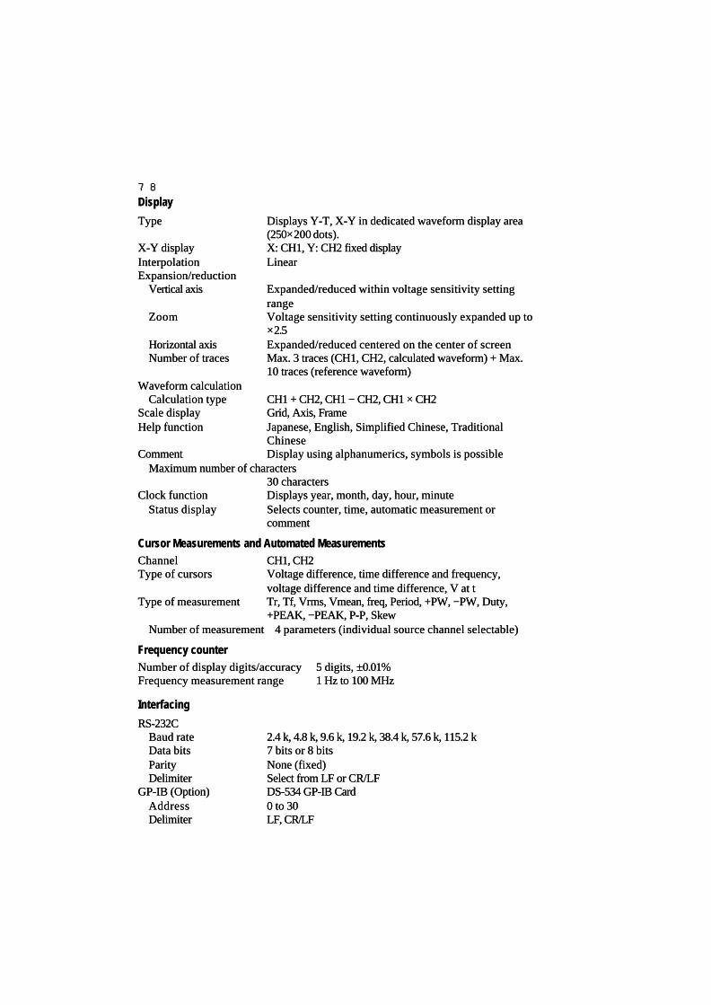
7878
DisplayDisplay
TypeType Displays Y-T, X-Y in dedicated waveform display areaDisplays Y-T, X-Y in dedicated waveform display area(250(250××200 dots).200 dots).
X-Y displayX-Y display X: CH1, Y: CH2 fixed displayX: CH1, Y: CH2 fixed displayInterpolationInterpolation LinearLinearExpansion/reductionExpansion/reduction
Vertical axisVertical axis Expanded/reduced within voltage sensitivity settingExpanded/reduced within voltage sensitivity settingrangerange
ZoomZoom Voltage sensitivity setting continuously expanded up toVoltage sensitivity setting continuously expanded up to××2.52.5
Horizontal axisHorizontal axis Expanded/reduced centered on the center of screenExpanded/reduced centered on the center of screenNumber of tracesNumber of traces Max. 3 traces (CH1, CH2, calculated waveform) + Max.Max. 3 traces (CH1, CH2, calculated waveform) + Max.
10 traces (reference waveform)10 traces (reference waveform)Waveform calculationWaveform calculation
Calculation typeCalculation type CH1 + CH2, CH1 CH1 + CH2, CH1 −− CH2, CH1 CH2, CH1 ×× CH2 CH2Scale displayScale display Grid, Axis, FrameGrid, Axis, FrameHelp functionHelp function Japanese, English, Simplified Chinese, TraditionalJapanese, English, Simplified Chinese, Traditional
ChineseChineseCommentComment Display using alphanumerics, symbols is possibleDisplay using alphanumerics, symbols is possible
Maximum number of charactersMaximum number of characters30 characters30 characters
Clock functionClock function Displays year, month, day, hour, minuteDisplays year, month, day, hour, minuteStatus displayStatus display Selects counter, time, automatic measurement orSelects counter, time, automatic measurement or
commentcomment
Cursor Measurements and Automated MeasurementsCursor Measurements and Automated MeasurementsChannelChannel CH1, CH2CH1, CH2Type of cursorsType of cursors Voltage difference, time difference and frequency,Voltage difference, time difference and frequency,
voltage difference and time difference, V at tvoltage difference and time difference, V at tType of measurementType of measurement Tr, Tf, Vrms, Vmean, freq, Period, +PW, Tr, Tf, Vrms, Vmean, freq, Period, +PW, −−PW, Duty,PW, Duty,
+PEAK, +PEAK, −−PEAK, P-P, SkewPEAK, P-P, SkewNumber of measurementNumber of measurement 4 parameters (individual source channel selectable) 4 parameters (individual source channel selectable)
Frequency counterFrequency counterNumber of display digits/accuracyNumber of display digits/accuracy 5 digits, 5 digits, ±±0.01%0.01%Frequency measurement rangeFrequency measurement range 1 Hz to 100 MHz1 Hz to 100 MHz
InterfacingInterfacing
RS-232CRS-232CBaud rateBaud rate 2.4 k, 4.8 k, 9.6 k, 19.2 k, 38.4 k, 57.6 k, 115.2 k2.4 k, 4.8 k, 9.6 k, 19.2 k, 38.4 k, 57.6 k, 115.2 kData bitsData bits 7 bits or 8 bits7 bits or 8 bitsParityParity None (fixed)None (fixed)DelimiterDelimiter Select from LF or CR/LFSelect from LF or CR/LF
GP-IB (Option)GP-IB (Option) DS-534 GP-IB CardDS-534 GP-IB CardAddressAddress 0 to 300 to 30DelimiterDelimiter LF, CR/LFLF, CR/LF

7979
Panel setting/waveform data save/recallPanel setting/waveform data save/recall
SETUPSETUPSAVE/UNDO functionSAVE/UNDO function Save/undo (internal memory) of panel setting usingSave/undo (internal memory) of panel setting using
single keysingle keyREFREF
SAVE/CLEAR functionSAVE/CLEAR function Display/erasure (internal memory) of reference waveformDisplay/erasure (internal memory) of reference waveformusing single keyusing single key
SAVE/RECALL functionSAVE/RECALL functionMediumMedium ATA card, floppy diskATA card, floppy diskData typeData type Panel setting, waveform data (CH1, CH2 simultaneously)Panel setting, waveform data (CH1, CH2 simultaneously)Record formatRecord format Waveform data selectable from binary or ASCIIWaveform data selectable from binary or ASCII
Only binary for panel settingOnly binary for panel settingRecord countRecord count Per data type and record formatPer data type and record format
ATA card: Max. 9999ATA card: Max. 9999Floppy disk: Max. 200Floppy disk: Max. 200
Time stampTime stamp Saves time and comment simultaneously (time unit: sec)Saves time and comment simultaneously (time unit: sec)Auto Save functionAuto Save function Saves waveform data for every acquisition of waveformSaves waveform data for every acquisition of waveform
Hard CopingHard Coping
Type of copy devicesType of copy devices Built-in printer, Floppy Disk, ATA Card, CentronicsBuilt-in printer, Floppy Disk, ATA Card, CentronicsOutput sourceOutput source Screen, panel settingScreen, panel settingAuto Copy functionAuto Copy function Outputs screen hard copy for every acquisition ofOutputs screen hard copy for every acquisition of
waveformwaveformInternal printerInternal printer
TypeType Line Thermal PrinterLine Thermal PrinterPaper widthPaper width 80 mm80 mm××48 48 , , 75microns, Thermal paper 75microns, Thermal paperPaper feedPaper feed AvailableAvailableRoll printRoll print AvailableAvailable
Floppy, ATA CardFloppy, ATA CardFormatFormat TIFF, BMPTIFF, BMPRecord countRecord count Per data type and record formatPer data type and record format
ATA card: Max. 9999ATA card: Max. 9999Floppy disk: Max. 200Floppy disk: Max. 200
CentronicsCentronicsFormatFormat DPU-414, ESC-P09, ESC-P24, PC-PR201, TIFF, BMPDPU-414, ESC-P09, ESC-P24, PC-PR201, TIFF, BMP
φφ

8080
Calibration signal outputCalibration signal output
WaveformWaveform Square waveformSquare waveformOutput voltageOutput voltage 0.6 V 0.6 V ±± 1% 1%FrequencyFrequency 1 kHz 1 kHz ±± 0.01% 0.01%
Other functionsOther functions
Auto setupAuto setup With UNDO functionWith UNDO functionSelf-calibration functionSelf-calibration function Calibrates sensitivity, offset, sync level.Calibrates sensitivity, offset, sync level.LCD reverse videoLCD reverse video White background, blue backgroundWhite background, blue background
Power supplyPower supply
Input voltageInput voltage 100 to 240 VAC100 to 240 VACFrequencyFrequency 50/60 Hz50/60 HzPower consumptionPower consumption
When printer is operatingWhen printer is operating 90 VA Max. (75 W Max.)90 VA Max. (75 W Max.)When printer is not operatingWhen printer is not operating 75 VA Max. (59 W Max.)75 VA Max. (59 W Max.)
Weight, dimensionsWeight, dimensionsWeightWeight Approx. 3 kgApprox. 3 kgDimensionsDimensions 215 (W) 215 (W) ×× 1700 (H) 1700 (H) ×× 166 (L) mm (excluding protrusions) 166 (L) mm (excluding protrusions)
Environmental conditionsEnvironmental conditions For indoor use onlyFor indoor use only
Specification assurance temperatureSpecification assurance temperature1010°°C to 35C to 35°°CC
OperatingOperating temperaturetemperature 00°°C to 40C to 40°°CChumidityhumidity 80% RH or less (at 4080% RH or less (at 40°°C)C)
StorageStorage temperaturetemperature −−1010°°C to 60C to 60°°CChumidityhumidity 80% RH or less (at 6080% RH or less (at 60°°C)C)
AltitudeAltitudeIn operationIn operation 2,000 m, atmosphere: approx. 79 kPa2,000 m, atmosphere: approx. 79 kPaNot in operationNot in operation 15,000 m, atmosphere: approx. 12 kPa15,000 m, atmosphere: approx. 12 kPa
Warm-up timeWarm-up time The specifications for this instrument are the assuredThe specifications for this instrument are the assuredvalues after more than 30 min of power on.values after more than 30 min of power on.
EC Declaration of ConformityEC Declaration of ConformityThe Oscilloscope meets requirements of the EMC Direc-The Oscilloscope meets requirements of the EMC Direc-tive, 89/336/EEC, Low Voltage Directive, 73/23/EEC for Prod-tive, 89/336/EEC, Low Voltage Directive, 73/23/EEC for Prod-uct Safety.uct Safety.
Low Voltage DirectiveLow Voltage Directive EN61010-1:93+A2:95,EN61010-1:93+A2:95,Safety Requirements for electrical equipment for measure-Safety Requirements for electrical equipment for measure-ment, control and laboratory use.ment, control and laboratory use.Do not operate in environments where conductive pollut-Do not operate in environments where conductive pollut-ants may be present.Installation Category CAT ants may be present.Installation Category CAT ⅡⅡ ..Local-level mains, appliances, portable equipment.Local-level mains, appliances, portable equipment.Pollution Degree 2.Pollution Degree 2.

Commands ManualCommands Manual

i
Contents
1. GP-IB Interface ......................................................................................................... iii
1.1 General ............................................................................................................ iii 1.2 Restrictions ..................................................................................................... iv 1.3 Remote Commands ......................................................................................... iv 1.4 Commands and Queries....................................................................................v 1.5 Local and Remote Modes.................................................................................v 1.6 Message Format .............................................................................................vii 1.7 Multi-commands............................................................................................vii 1.8 Query .............................................................................................................. ix 1.9 Header Mnemonic............................................................................................ x 1.10 Delimiter (<Program/Response Message Terminator>) ................................ xv 1.11 Input and Output Buffers .............................................................................. xv
2. Remote Control through a GP-IB Interface .........................................................xvi
2.1 GP-IB Structure ............................................................................................ xvi 2.2 Interface Functions....................................................................................... xvii 2.3 Hardware Addressing................................................................................... xvii 2.4 GP-IB Signals .............................................................................................. xviii 2.4.1 Data Lines ................................................................................................... xviii 2.4.2 Handshake Lines ......................................................................................... xviii 2.4.3 Interface Control Lines................................................................................ xviii 2.5 IEEE 488.1 Messages.....................................................................................xix 2.5.1 DCL and SDC ................................................................................................xix 2.5.2 GET (Group Execute Trigger).........................................................................xx 2.5.3 REN: Remote ENable.....................................................................................xxi 2.5.4 LLO: Local LOcout ........................................................................................xxi 2.5.5 GTL: Go To Local .........................................................................................xxi 2.5.6 IFC: InterFace Clear.....................................................................................xxiii 2.6 Service Request and Status Register.............................................................xxiii 2.6.1 Service Requests (SRQ) ...............................................................................xxiii 2.6.2 Status Register..............................................................................................xxiv 2.6.3 Status Byte Register....................................................................................xxvii 2.6.4 Service Request Enable Register (SRE)......................................................xxviii 2.6.5 Standard Event Status Register ..................................................................xxviii 2.6.6 Standard Event Status Enable Register.........................................................xxix

ii
2.6.7 Output Queue ..............................................................................................xxix 2.6.8 Trigger Event Status Register.......................................................................xxix 2.6.9 Trigger Event Status Enable Register ............................................................xxx 2.7 Instrument Polling.........................................................................................xxx 2.7.1 Continuous Polling........................................................................................xxx 2.7.2 Serial Polling..................................................................................................xxx
3. Remote Control through an RS -232C Interface................................................xxxi
3.1 Signal Line and Connector Pins....................................................................xxxi 3.2 Connection with External Devices ..............................................................xxxii 3.3 Communication Mode.................................................................................xxxii 3.4 Processing conducted by the Controller.....................................................xxxiii 3.5 To Go to Remote.......................................................................................xxxiv 3.6 Service Request and Status Register...........................................................xxxiv
4. Hardware-Specific Commands ..........................................................................xxxiv

iii
PC
PC
SignalGenerator
TestEquipment
GPIB
RS-232C
1. GP-IB Interface 1.1 General
The DS-8812 can be operated by remote control through an external controller (usually a computer) in almost the same way as when you operate it manually using buttons and knobs.
Data on waveforms, screens, and panel setup can also be transferred by remote control. So you can send data directly to the computer without using floppy disks or an ATA card, and configure the automatic measurement system.
There are two ways to operate the DS-8812 by remote control, as described below.
(1) Through an optional GP-IB interface
(2) Through the standard RS-232C interface
To connect the DS-8812 and a remote computer through the GP-IB interface, insert a GP-IB board or card into the expansion slot of the computer. Because up to 15 devices can be connected to one system through the GP-IB interface, it is useful to control the DS-8812 from multiple remote devices.
An RS-232C interface is installed on most computers, so you can easily connect the DS-8812 to a remote computer. But, unlike the GP-IB, an RS-232C can interface with only one computer, and takes more time to transfer data because it is a serial bus.
* Example of GP-IB and RS-232C Interface
iv
1.2 Restrictions
To operate the DS-8812 by remote control through a GP-IB or RS-232C interface, you must observe the following restrictions.
• Remote control cannot be performed using a RS-232C and GP-IB simultaneously. (If one remote control mode is active, the other should be disabled.)
• Remote control operations are not permitted while the floppy disk or the ATA card is being accessed.
• Remote control operations are not permitted while data is being output to a printer.
If any of the above is performed, the handshake will be interrupted. To resume the handshake, turn off the power and turn it back on again.
The DS-8812 cannot control the following functions by remote control.
• Power-on and power-off • Roll printing using the internal printer • Output to a Centronics port • Operations associated with access to an ATA card • Operations associated with access to a floppy disk • Auto Save and Auto Copy functions • Setup for Interface menu items • Contrast setup, language selection, LCD reverse display, and automatic correction
The DS-8812 automatically sets the following item by remote control.
• The Offset items in the CH1 and CH2 menus are set to "Division." 1.3 Remote Commands
To operate the DS-8812 by remote control, the controller transmits program messages according to the format structure.
The DS-8812 remote commands conform to IEEE 488.2 for the General-Purpose Interface Bus (GP-IB). Some of these commands interface are also supported by the RS-232C interface.
In this manual, the elements defined in IEEE 488.2 are given as follows.
<Program Message> <Character Program Data> <Numeric Program Data> Suffix

v
<String Program Data> <Arbitrary Block Program Data> <Response Message> <Character Response Data> <NR1 Numeric Response Data> <NR3 Numeric Response Data> <String Response Data> <Fixed Length Arbitrary Block Response Data> <Arbitrary ASCII Response Data>
1.4 Commands and Queries
A program message is composed of one or more commands or queries. The commands are used to set items such as sweep time and voltage sensitivity.
Queries are used to prompt connected devices to report their settings. The same characters are used in commands and queries except that "?" is added at the end of a query. When the DS-8812 receives a query from the controller, it returns a response message. Please note that the time required to return the response message to the controller depends on the status of the DS-8812 and the type of command received.
1.5 Local and Remote Modes
After power-on, the DS-8812 enters local mode, in which you can operate it with the buttons and knobs on the front panel.
'TDIV 1 µs'→
'TDIV ?'→
+1.00000E-6←
Command Query
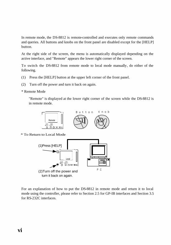
vi
In remote mode, the DS-8812 is remote-controlled and executes only remote commands and queries. All buttons and knobs on the front panel are disabled except for the [HELP] button.
At the right side of the screen, the menu is automatically displayed depending on the active interface, and "Remote" appears the lower right corner of the screen.
To switch the DS-8812 from remote mode to local mode manually, do either of the following.
(1) Press the [HELP] button at the upper left corner of the front panel.
(2) Turn off the power and turn it back on again.
* Remote Mode
"Remote" is displayed at the lower right corner of the screen while the DS-8812 is in remote mode.
For an explanation of how to put the DS-8812 in remote mode and return it to local mode using the controller, please refer to Section 2.5 for GP-IB interfaces and Section 3.5 for RS-232C interfaces.
PC
(1)Press [HELP]
(2)Turn off the power andturn it back on again.
Local
* To Return to Local Mode
Remote
Button Knob
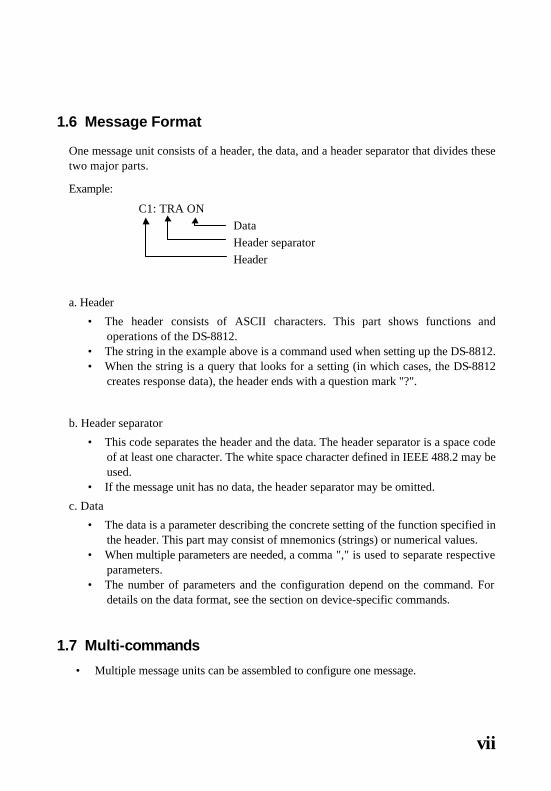
vii
1.6 Message Format
One message unit consists of a header, the data, and a header separator that divides these two major parts.
Example:
C1: TRA ON Data Header separator Header
a. Header
• The header consists of ASCII characters. This part shows functions and operations of the DS-8812.
• The string in the example above is a command used when setting up the DS-8812. • When the string is a query that looks for a setting (in which cases, the DS-8812
creates response data), the header ends with a question mark "?".
b. Header separator
• This code separates the header and the data. The header separator is a space code of at least one character. The white space character defined in IEEE 488.2 may be used.
• If the message unit has no data, the header separator may be omitted.
c. Data
• The data is a parameter describing the concrete setting of the function specified in the header. This part may consist of mnemonics (strings) or numerical values.
• When multiple parameters are needed, a comma "," is used to separate respective parameters.
• The number of parameters and the configuration depend on the command. For details on the data format, see the section on device-specific commands.
1.7 Multi-commands
• Multiple message units can be assembled to configure one message.

viii
• Respective message units are separated and connected with a semicolon ";". Multi-commands are not available for query or execution command.
C1: TRA ON;C2: TRA ON Message unit Message unit separator Message unit
• The device-specific commands for the DS-8812 are a hierarchical command called
"compound command program header". For example, the parent command C1 can be combined with subcommands such as TRA, VDIV, and CPL to build a header (e.g., :C1:TRA ON or :C1:VDIV 5). When the message units, each of which has a header composed of a common parent command, are combined to build one message, the parent command may be omitted on the second and following message units. With the DS-8812, the number of hierarchies in the compound command program header is up to two.
Example: C1: TRA ON: C1:VDIV 50mV; C1:CPL DC The above message can be written in the following format. C1:TRA ON; VDIV 50mV; CPL DC This function specifies the parent command C1 as the header path.
• The header path designation is effective until the current header path is changed. In the next message, the parent command in the previous message unit is defined as the header path for the message. The header colon ":" at the beginning of the message may be omitted.
Example: C1:TRA ON; :C1 VDIV 50mV;:C1:CPL DC
In the message above, the colon in the header can be omitted, as shown below. C1: TRA ON:C1 VDIV 50mV; C1:CPL DC Example: C1:TRA ON: VDIV 50mV; CPL DC
The following command is sent after the above message.
TRA OFF: VDIV 20mV:CPL DC

ix
The header path is executed as CH1.
• The above header rules do not apply to common commands defined in IEEE 488.2 (such as *WAI and *OPC). Each common command is executed by ignoring the header path. However, this does not mean that the preceding header path designation is not canceled. To interpret the message units defined after a common command, the previous header path designation works well.
Example:
C1:TRA ON:*WAI: VDIV50mV; CPL DC The header path is CH1 The common command *WAI is
executed.
• While the DS-8812 supports multi-command (the function that assembles multiple message units into one message) when operating in remote control mode, it does not support the query and execution commands. The multi-command should not be used for query and execution commands. Instead, each query should be sent on its own in one message. Commands for which multi-command is not supported:
REFSAV, REFRCL, *TRG, WSGL, ASET, COPY 1.8 Query
• A message whose header ends with a question mark "?" is called a query. The query is a command used to inquire settings and measurement results. Upon reception of a query, the DS-8812 creates a response message and stores it in the output queue.
• When (a part of) the response message remains in the output queue and a new message is received, the current contents of the output queue are cleared, causing a query error (service request event).
• The multi-command function does not support queries. Each query should be sent on its own in one message.
• The header mnemonic is not added to the query response data. Example: IE-6 is used for C1:VDIV?.

x
1.9 Header Mnemonic
• The header mnemonic is formed from ASCII codes for A to Z and 0 to 9. • ASCII's A-Z characters are not case-sensitive. In other words, there is no
distinction between uppercase and lowercase letters, as they are interpreted in the same way.

xi
a. <Character Program Data> / <Character Response Data>
• As with header mnemonics, <Character Program Data> and <Character Response Data> are data are formed from a combination of ASCII codes for A to Z and 0 to 9.
C1:TRA ON In this example, ON, which is the parameter for the TRACE command, serves as the <Character Program Data>.
• As with the header mnemonic, the ASCII codes used in <Character Program Data> are not case-sensitive.
• The DS-8812 always creates uppercase character response data for the <Response Message>.
b. <Numeric Program Data> / <Numeric Response Data>
• Numerical data can be formatted as an integer (NR1), real number (NR2), or exponent (NR3). If the message is described in the form of "VDIV 50m V", "50m V" corresponds to the numeric program data. The following numerical values are all interpreted as identical values.
0.05 = 50E-3=5e-2=5E-2V=50mV • The suffix showing physical unit "V" or "mV" is divided into two parts: one is the
unit itself (e.g., V (volts) or Hz (hertz)); and the other is the multiplier for the unit, i.e., m (milli) or k (kilo).
• Any characters can be used to specify the suffix units involved. • Numeric response data that is created by the DS-8812 as a <Response Message>
has no suffix. • Mnemonics used to indicate the multiplier for the suffix are defined as follows.
Some commands allow the suffix to be located after this data.
Definition Mnemonic Definition Mnemonic 1E18 EX 1E-3 M 1E15 PE 1E-6 U 1E12 T 1E-9 N 1E9 G 1E-12 P 1E6 MA 1E-15 F 1E3 K 1E-18 A The mnemonic is not case-sensitive.

xii
u The <Numeric Program Data> received by the DS-8812 can have any of the formats listed below.
• NR1 (integer) (number of effective digits: 6)
• NR2 (decimal number) (number of effective digits: 6)
• NR3 (exponent) (number of effective digits - mantissa: 6, index: 2)
The mantissa is an integer or decimal number. The index is an integer.
Number
Number Number
Mantissa Index
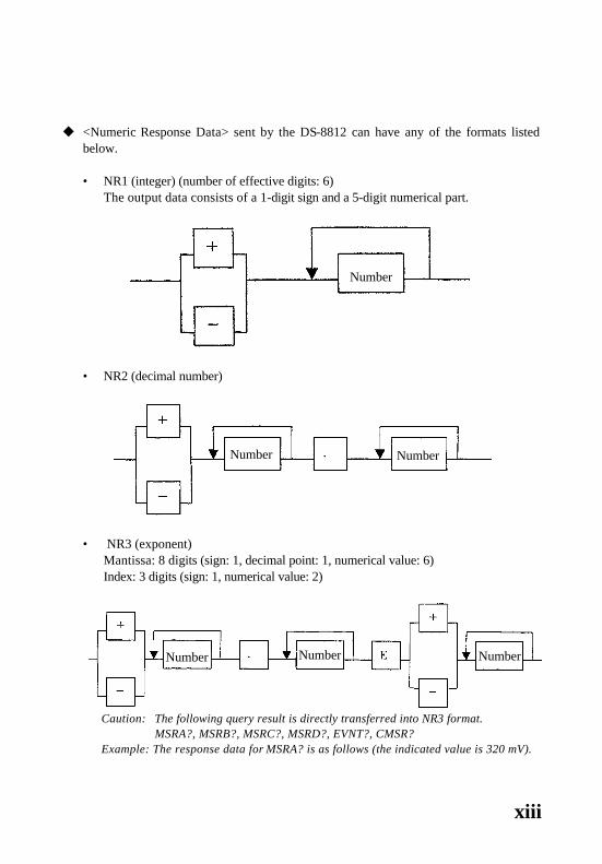
xiii
u <Numeric Response Data> sent by the DS-8812 can have any of the formats listed below.
• NR1 (integer) (number of effective digits: 6)
The output data consists of a 1-digit sign and a 5-digit numerical part.
• NR2 (decimal number)
• NR3 (exponent) Mantissa: 8 digits (sign: 1, decimal point: 1, numerical value: 6) Index: 3 digits (sign: 1, numerical value: 2)
Caution: The following query result is directly transferred into NR3 format. MSRA?, MSRB?, MSRC?, MSRD?, EVNT?, CMSR? Example: The response data for MSRA? is as follows (the indicated value is 320 mV).
Number
Number Number
Number Number Number

xiv
+320E-3

xv
c. Binary block data
• This data is used to send or receive large amounts of data such as waveforms. • When the specified amount of data differs from the amount of data actually sent
through the binary data transfer, an error may occur on the subsequent operation. If the amount of data specified is incorrect, the GP-IB system may hang up. To reset the hang-up status, the IFC signal and DCL or SDC command must be used.
• When transferring binary block data, the code specified as a delimiter is not distinguished from the data. If you want to send binary data to the DS-8812, send only the data (i.e., do not use a delimiter). When the binary data is read, delimiter-free data is sent to the DS-8812.
• When the last byte of the binary block data is sent, the DS-8812 sets the EOI signal to "TRUE".
• If the DS-8812 receives an EOI signal or the specified amount of data, it determines that the binary block data transfer is completed. Therefore, if the specified amount of data differs from the amount of data actually received, an error occurs.
• Note that the DS-8812 is not compatible with paths starting with #0, among <ARBITRARY BLOCK PROGRAM DATA> defined in IEEE 488.2.
1.10 Delimiter (<Program/Response Message Terminator>)
• If the DS-8812 sends <Response Message>, the user can select LF or CR/LF as a delimiter (<Response Message Terminator>).
• EOI is always sent. • The delimiter should be defined in the UTILITIES menu. • When the DS-8812 receives the program message, it recognizes any of LF, CR/LF,
or EOI as the delimiter. Note that this recognition is independent of the delimiter setting.
1.11 Input and Output Buffers
• The DS-8812 supports a 256-byte input buffer. • When the DS-8812 receives a delimiter, it begins to interpret the commands in the
buffer even if the input buffer is not full. The DS-8812 does not receive next messages when interpreting or executing received commands. Once the interpretation and execution of commands is completed, the DS-8812 resumes its handshake.

xvi
• When the input buffer is full, data exceeding 256 bytes is discarded. The message to be set must not exceed 256 bytes.
• The DS-8812 supports a 256-byte output buffer. • When transferring binary block data, data exceeding 256 bytes can be sent.
2. Remote Control through a GP-IB Interface This chapter describes how to control the DS-8812 remotely through the General-Purpose Interface Bus (GP-IB).
To use the GP-IB interface, insert the device-specific DS-534 GP-IB card into the card slot at the rear panel. For details, please refer to the operation manual.
2.1 GP-IB Structure
GP-IB Structure
A GP-IB is similar to an ordinary computer bus. The only difference is that the computer has a bus board, which is interconnected via a back-plane bus while the GP-IB interconnects devices through cables. Both buses transmit program and interface messages.
The program message is often called a device-dependent message. It contains programming commands, measurement results, the status of the measuring instrument, and waveform data. Chapter 2 describes the general format for program messages.
The interface message is used to manage the bus. It initializes the bus, allocates and deallocates device addresses, switches between remote and local mode, and performs other functions.
A device on the GP-IB can serve as listener, talker, or controller, or all three. The talker sends program messages to multiple listeners. The controller sends interface messages to each device and manages the flow of information on the bus.
The oscilloscope can be a talker or a listener, but it cannot be a controller. The host computer, however, must execute all three modes. Please refer to the GP-IB interface manual for details on the method in which the controller configures the GP-IB to perform a specific function.

xvii
2.2 Interface Functions
The DS-8812 interface has the following functions defined in IEEE 488.1.
The DS-8812 supports the following IEEE 488.1 subsets.
Subset Function SH1 Supports all source handshake functions. AH1 Supports all acceptor handshake functions. T6 Specifies and cancels the talker by means of basic talker, serial poll, and
MLA. The talk-only function is not supported. TE0 Does not support the extended talker function. L4 Specifies and cancels the listener by means of basic talker and MTA. LE0 Does not support the extended listener function. SR1 Supports all the service request functions. RL2 Supports all the remote local functions. The local lockout function is not
supported. PP0 Does not support the parallel poll function. DC1 Supports all device clear functions. DT1 Supports all device trigger functions. Co Does not support the controller function.
2.3 Hardware Addressing
• Any address can be set from 0 to 30 as the listener and talker address. (The listener and the talker use a common address.)
• When the system is reset, the GP-IB device address is set to 10. • To access the address change menu, "GP-IB" should be selected from "Interface" in
the UTILITIES menu. Note that if the specified GP-IB card has not been mounted, this GP-IB menu cannot be selected.

xviii
2.4 GP-IB Signals
GP-IB Signals
The GP-IB bus system is composed of sixteen signal lines and eight ground (GND) lines; the ground lines are also called shield lines. The signal lines are categorized into the following three groups.
• Eight data lines • Three handshake lines • Five interface control lines
2.4.1 Data Lines
Generally, eight data lines are called DI01 - DI08. They are used to transmit program and interface messages. DI08 is often blank, as most messages use 7-bit ASCII codes.
2.4.2 Handshake Lines
These three handshake lines are used to manage the message byte exchange between the devices. This process is called the 3-line interlock handshake. It ensures that the message bytes on the data line can be transmitted and received without errors.
2.4.3 Interface Control Lines
The following five lines control the flow of information on the interface.
ATN: AtteNtion When a message such as the talk address, the listen address, and device clear (DCL) is sent on the data line, the controller sets ATN to TRUE. When ATN is set to FALSE, the bus is in data mode so that the talker can transmit program messages to the listeners.
IFC: InterFace Clear When initializing the bus, the controller sets the IFC to TRUE for a period of time.
REN: Remote Enable The controller uses this line to put the device into remote or local mode.
xix
SRQ: Service ReQuest Any device can request services by setting SRQ to TRUE. The device does not have to be synchronized with the controller. This line is the same as the single interrupt line on a computer bus.
EOI :End Or Identify This line is used in two ways. The talker uses this line to end the message string. The controller uses this line to instruct the device to identify each response in parallel polling (as described later).
2.5 IEEE 488.1 Messages
The IEEE 488.1 defines the GP-IB mechanical and electrical systems as well as the transfer protocols in the lower layers. The definitions include how the controller addresses the devices, switches them to talker or listener mode, and switches them between remote and local mode. These interface messages are sent on the GP-IB interface control line (usually, ATN is set to TRUE).
Unlike the commands which are executed in the order of input, these messages are executed as soon as they are received, except for GET.
Note 1: IEEE 488.2 defines standard program messages such as command headers, in addition to the interface messages in IEEE 488.1. Program messages are identified by a prefixed asterisk <*>, and are listed in the system command section.
The system command section does not list the commands to clear the input/output buffers and to put the oscilloscope into the remote state because they have been already defined in IEEE 488.1. For details, please refer to the host computer GP-IB interface manual and the support program, which contain special calls to execute these messages.
The following subsections describe IEEE 488.1 messages that reconfigure the bus and control the oscilloscope.
2.5.1 DCL and SDC
• Upon receiving the universal command DCL (Device Clear), the DS-8812 initializes the device function. The same initialization occurs when the DS-8812 is being set the DS-8812 to “listener” and receives the address command SDC (Selected Device Clear).

xx
• The DCL or SDC message shows that the following initialization is being executed. 1) Data input/output is terminated, and the input and output buffers and the
output queue are cleared. The MAV bit and status byte register are also cleared. As a result, the MSS bit may be affected by these operations.
2) If active, the command mode is changed from RUN to STOP. 2.5.2 GET (Group Execute Trigger)
When the DS-8812 is being set the DS-8812 to “as listener” and receives the address command GET, the sweep method is set to "SINGLE" and the DS-8812 enters RUN command mode.

xxi
2.5.3 REN: Remote ENable
To switch the DS-8812 operation mode from local to remote, set the DS-8812 as listener (so that the MLA is received) while the REN line is true (low signal output).
In the remote mode, all front-panel switches and controls are disabled, except for the [HELP] button. The GP-IB menu is automatically displayed at the right side of the screen. “Remote” at the lower right corner indicates that the DS-8812 is in remote mode.
When the controller resets the REN line to false (high signal output), all devices on the bus are put in local mode again. The Go To Local (GTL) message is used to return each device to local mode.
2.5.4 LLO: Local LOcout
The DS-8812 does not support the local lockout command to hide the local menu.
Local Lockout
The Local Lockout (LLO) command hides the local menu. The LLO command can be transmitted in both local and remote modes if the oscilloscope is set to remote mode.
2.5.5 GTL: Go To Local
The Go To Local (GTL) message places the oscilloscope back into local mode. When the oscilloscope is in local mode, all front panel switches and controls are enabled and the normal menu is displayed. The oscilloscope returns to remote mode as soon as it is set to listener mode.
Please note that even the GTL message cannot clear an active local lockout. Therefore, the oscilloscope goes back into local mode as soon as it is put in remote mode, unless the local lockout is deactivated.
Do not position the GTL message directly after the command string. Otherwise, the oscilloscope will enter local mode again before finishing decoding of all commands in the input buffer. This will happen because the GTL message is executed immediately after it is decoded. The oscilloscope will not execute further commands, even if another command is sent to reset the oscilloscope to remote mode. To decode the entire

xxii
command, add a query in the command string (e.g., "*STB?") and wait for a response before sending the GTL message.

xxiii
2.5.6 IFC: InterFace Clear
The InterFace Clear (IFC) message initializes the GP-IB, but does not influence oscilloscope operation.
2.6 Service Request and Status Register
While the oscilloscope is under remote control, asynchronously occurring events can not be predicted by the controller. A typical example is that the oscilloscope is waiting for a trigger and cannot respond to a query from the controller requesting a waveform.
The service request (SRQ) effectively detects events in the oscilloscope. This GP-IB interrupt line is used to interrupt controller program execution. In this way, the controller can execute other programs while waiting for responses from queried devices.
The controller interface must support interrupts to use the SRQ. If not, the controller reads out lines continuously or periodically until it detects the transition, which requires an event-related status bit.
2.6.1 Service Requests (SRQ)
• If an operation is completed or an error occurs, the DS-8812 outputs a service request (i.e., it sets the SRQ line to "L").
• While only one SRQ line, which is wired-OR connection, is used on the bus line for the service request, the DS-8812 has multiple service request events. To identify the cause of the service request, the controller must execute a serial poll or read the internal status register of the DS-8812.
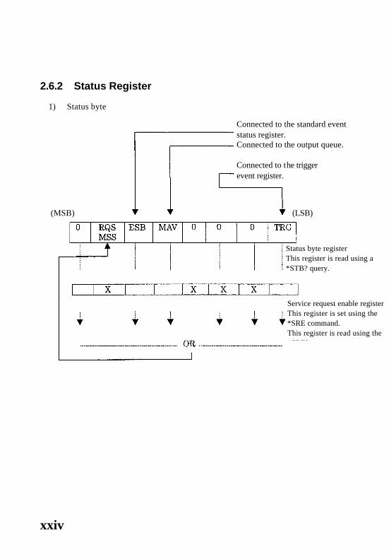
xxiv
2.6.2 Status Register
1) Status byte
Connected to the standard event status register. Connected to the output queue.
Connected to the trigger event register.
Status byte register This register is read using a *STB? query.
Service request enable register This register is set using the *SRE command. This register is read using the *SRE? query.
(MSB) (LSB)
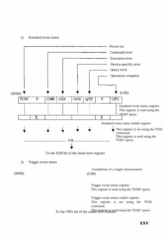
xxv
2) Standard event status
To the ESB bit of the status byte register
3) Trigger event status
(MSB)
Power-on
Command error
Execution error
Device-specific error
Query error
Operation complete
(LSB)
Standard event status register This register is read using the *ESR? query.
Standard event status enable register
This register is set using the *ESE command. This register is read using the *ESE? query.
Completion of a single measurement (MSB) (LSB)
Trigger event status register This register is read using the TESR? query. Trigger event status enable register This register is set using the TESE command. This register is read using the TESE? query. To the TRG bit of the status byte register

xxvi

xxvii
2.6.3 Status Byte Register
• This register allows serial polling via the GP-IB system bus or a readout using a *STB? query.
• This register is the last stage of the DS-8812's hierarchical status information. • This register consists of 8 bits; these bits have the following contents.
(Bit 7) : The DS-8812 does not use bit 7 of the status byte register. Bit 7 is always set to 0.
RQS (bit 6) : When serial polling is executed, a message is returned as bit 6 of the status byte. A message is generated when other bits in the status byte register (ESB, MAV,..., TRG) are masked by the service request enable register, and consequently, the logical sum of all bits are changed from 0 to 1. RQS is cleared when the power is turned on or serial polling is executed.
MSS (bit 6) : A message is returned as bit 6 of the *STB? query response. MSS connects the logical sum of all bits when other bits in the status byte register (ESB, MAV,..., TRG) are masked by the service request enable register.
ESB (bit 5) : A message is returned as bit 5 of the serial poll or *STB? query response. This is a summary message connected to the logical sum when the standard event status register is masked by ESE.
MAV (bit 4) : A message is returned as bit 4 of the serial poll or *STB? query response. This is a summary message connected to the output queue.
(Bit 3) : The DS-8812 does not use bit 3 of the status byte register. Bit 3 is always set to 0.
(Bit 2) : The DS-8812 does not use bit 2 of the status byte register. Bit 2 is always set to 0.
(Bit 1) : The DS-8812 does not use bit 1 of the status byte register. Bit 1 is always set to 0.
TRG (bit 0) : A message is returned as bit 0 of the serial poll or *STB? query response. This is a summary message connected to the trigger event status register.
xxviii
2.6.4 Service Request Enable Register (SRE)
• The service request enable register masks the status byte register. A message is returned to the RQS or MSS bit, depending on the result of masking. This register masks the SRQ output.
• The mask pattern can be set using the *SRE command and read using the *SRE? query.
• The contents of this register are cleared (that is, set to 0) when the power is turned on.
• This register does not change even if the device clear or *CLS command is input. 2.6.5 Standard Event Status Register
• The standard event status register is defined in the IEEE 488.2 standard. • This register can be read using the *ESR? query. After the contents of this register
are masked by the standard event status enable register, the logical sum of all bits is connected to the ESB bit of the status byte register in real time.
• The contents of this register are cleared (that is, set to 0) when the register is read using the *CLS command or *ESR? query.
• This register consists of 8 bits, and each bit has the following contents.
PON (bit 7) : After the power is turned on, this bit is set to 1.
(Bit 6) : The DS-8812 does not use bit 6. Bit 6 is always set to 0.
CME (bit 5) : If a command error occurs, this bit is set to 1. This indication shows that some error exists in the command syntax.
EXE (bit 4) : If an execution error occurs, this bit is set to 1. This indication shows that the command cannot be executed or could not be completely normally.
DDE (bit 3) : If a device-specific error occurs, this bit is set to 1. This indication shows that an error specific to the DS-8812 exists.
QYE (bit 2) : If a query error occurs, this bit is set to 1. This indication shows that an error occurs when the controller attempts to read the message from the DS-8812 without sending the query command, or the next message is sent before the response message has not been completely read.
(Bit 1) : The DS-8812 does not use bit 1. Bit 1 is always set to 0.

xxix
OPC (bit 0) : When the operation is completed, this bit is set to 1. This bit supports the *OPC-command-based controller-device synchronization.
2.6.6 Standard Event Status Enable Register
• The standard event status enable register masks the standard event status register. A message is returned to the ESB bit of the status byte register, depending on the results of masking.
• The mask pattern can be set using the *ESE command and read using an *ESE? query.
• The contents of this register are cleared (that is, set to 0) when the power is turned on.
• This register is not affected by the device clear or *CLS commands. 2.6.7 Output Queue
• The output queue is an output buffer in which the response message to the controller is stored.
• Appropriate response messages are stored in the output queue, depending on the type of query.
• The MAV bit of the status byte register is set to 1 so long as data of one byte or greater exists in the output queue.
• The contents of this output queue are cleared (that is, set to 0) when the power is turned on or the device clear command is executed. When the output queue is not empty and a new program message is sent before the controller reads all the data bytes, a query error occurs and the contents of the output queue are also cleared.
2.6.8 Trigger Event Status Register
• The trigger event status register reports the results of a single measurement. • After the contents of this register are masked by the trigger event status enable
register, the logical sum of all bits is connected to the TRG bit of the status byte register in real time.
• This register uses the lowest bit. The other bits are always recognized as 0. • The query used for to this register is TESR?. • The contents of this register are cleared (set to 0) when the power is turned on.

xxx
2.6.9 Trigger Event Status Enable Register
• The trigger event status enable register masks the trigger event status register. A message is returned to the TRG bit of the status byte register, depending on the results of masking.
• The mask pattern can be set using the TESE command and read using a TESE? query.
• The contents of this register are cleared (set to 0) when the power is turned on. • This register is not affected by the device clear or *CLS commands.
2.7 Instrument Polling
The remote computer can monitor the state transition in this instrument by polling a selected status register. The following subsections describe the polling method to detect a given event.
The instrument does not support the parallel polling function.
2.7.1 Continuous Polling
Continuous polling monitors the status register continuously until it detects a transition. This is the most direct way to detect a state change, but cannot be enabled in some conditions, as when multiple devices are installed.
2.7.2 Serial Polling
Serial polling is performed if the signal is output to the SRQ line. The controller checks the SRQ bit in the STB register for each device and determines which device generates the interrupt.
After serial polling is completed, the RQS bit in the STB register is cleared. Please note that other STB register bits are valid until either "CLS" or the device clear command is transmitted. No interrupts can be generated unless all these bits are cleared.
Serial polling is effective only if multiple devices must be monitored.

xxxi
3. Remote Control through an RS-232C Interface
RS-232C is a serial interface standard defined by the EIA according to CCITT Recommendations V.24 and V.28. This standard provides the electrical specifications for signal lines, the types and functions of signal lines, and the mechanical characteristics (connector specifications), but does not regulate the communication protocols.
All DS-8812 devices have an RS-232C port on their rear panel.
3.1 Signal Line and Connector Pins
The table below shows the connector pin assignment for RS-232C control.
Pin No.
Signal Function Remarks
1 CD (CD) Detection of the receive carrier
This pin number is not used with the DS-8812.
2 RD (RxD) Reception data 3 SD (TxD) Transmission data
4 ER (DTR) Data terminal ready This pin number is not used with the DS-8812.
5 SG (SG) Signal ground
6 DR (DSR) Data set ready This pin number is not used with the DS-8812.
7 RS (RTS) Transmission request 8 CS (CTS) Transmission enable
9 RI (CI) Select call This pin number is not used with the DS-8812.
• The connector for RS-232C control is a 9-pin jack. • The cable length should not exceed 15 m (9600 bps).

xxxii
3.2 Connection with External Devices
• Before connecting an external device to the DS-8812, be sure to turn off the DS-8812.
• To connect an external device to the DS-8812, use cross cables. The figure below gives an example of how to connect using cross cables.
Connector used on
the DS-8812 (9-pin connector)
Connector used on the external device (9-pin connector)
3.3 Communication Mode
The DS-8812 uses half-duplex communication.
In half-duplex communication, only one device can transmit at a time. When one device is sending a message, the other device has to wait until the message transfer is completed before it can start transmitting.
Because the serial interface uses one line to transmit data, you must match the settings between the DS-8812 and the controller. If they are different, the controller may fail to communicate with the DS-8812, and you must reset them manually.
To access the setup menu, "RS-232C" should be selected from "Interface" in the UTILITIES menu.

xxxiii
(1) Delimiter Choose CR/LF or LF.
(2) Baud rate Select the desired value from 2400, 4800, 9600, 38400, 57600, and 1152000. If an error occurs during data transmission, decrease the baud rate.
(3) Data Select 7 bits or 8 bits. To send binary data, use 8 bits.
(4) Parity bit This item is fixedly set to NONE.
(5) Stop bit This item is fixed to 1 bit.
3.4 Processing conducted by the Controller
In RS-232C remote control mode, an ACK code (06(H)) or NAK code (15(H)) is returned in response to every command. To create the remote program on the controller, you should follow the procedure given below.
Menu Interface RS 232C Delimiter CR/LF
Baud Rate 9600 Data 8 bits
Exit
Remote
Send a command/query
Wait to receive ACK or NAK
Receive the next command or query response.
Reset any command errors
Receive ACK
Receive NAK

xxxiv
3.5 To Go to Remote
Unlike a GP-IB, an RS-232C does not support IEEE 488.1 messages (see the Section 2.5).
The operation mode is switched from local to remote when the controller sends the command to the DS-8812.
In remote mode, all buttons and knobs on the front panel are disabled except for the [HELP] button. The RS-232C menu is automatically displayed at the right side of the screen. When "Remote" is displayed in the lower right corner, it means that the DS-8812 is in remote mode.
To switch the operation mode to local, press the [HELP] button.
3.6 Service Request and Status Register
Unlike the GP-IB, the RS-232C does not have an SRQ line (see the Section 2.6.1). To detect events in the oscilloscope, the controller reads out lines continuously or periodically until it detects a transition that requires an event-related status bit (serial poll).
The structure of the RS-232C's status register is the same as that for the GP-IB (see the Section 2.6.1).
4. Hardware-Specific Commands This chapter lists all commands and queries recognized by the DS-8812.
Each page contains one command, including its type (command, query, or both).
A query is a message whose header ends with a question mark (?). The commands are listed in alphabetical order.
Each command description begins with a brief explanation of the function to be executed, followed by the complete command syntax (header and format). The syntax and response format are also provided for some queries.

xxxv
Examples are given for most commands. For the GP-IB, it is supposed that a National Instruments interface board is installed in the controller, so each GP-IB example shows the BASIC interface subroutine call. "SCOPE%" is the DS-8812 device name.
Before starting programming, check command names in the following command group
<Command List> <Acquisition: Commands to control waveform acquisition>
Category Command Query Remarks See
page
ACQ ACQ? Sets up / reads out acquisition mode
1
AVGCNT AVGCNT? Sets up / reads out average time 3
EQU EQU? Sets up / reads out equivalent sample
30
MLEN MLEN? Sets up / reads out memory length 45
Acquisition
ROLL ROLL? Sets up / reads out roll mode 60 VDIV VDIV? Sets up / reads out vertical axis 99 CPL CPL? Sets up / reads out input coupling 11 ZOOM ZOOM? Sets up / reads out zooming 105 BWL BWL? Sets up / reads out bandwidth limit 4 PROBE PROBE? Sets up / reads out probe ratio 53
Vertical axis
OFST OFST? Sets up / reads out offset 49 RUN ------ Starts waveform acquisition 62 STOP ------ Aborts waveform acquisition 71 ASET ------ Executes auto setup 2
*TRG ------ Sets sweep mode to single and starts waveform acquisition
86
Operation
WSGL ------ Sets sweep mode to single and start waveform acquisition
103
TDIV TDIV? Sets up / reads out time base 75 Horizontal axis TRDL TRDL? Sets up / reads out trigger delay 84
SWMD SWMD? Sets up / reads out sweep mode 72 TTYP TTYP? Sets up / reads out trigger type 92 TSRC TSRC? Sets up / reads out trigger source 90 TCPL TCPL? Sets up / reads out trigger coupling 74
Acquisition
Trigger
TSLP TSLP? Sets up / reads out trigger slope 89

xxxvi
THTM THTM? Sets up / reads out hold-off time 80
EVNT EVNT? Sets up / reads out event trigger mode
34
TVFL VFL? Sets up / reads out TV synchronous field
94
TVLN TVLN? Sets up / reads out TV synchronous line
95
TLVL TLVL? Sets up / reads out trigger level 81

xxxvii
<Display: Display commands>
Category Command Query Remarks See
page TRA TRA? Sets up / reads out trace display 83 DTJN DTJN? Sets up / reads out dot joint 20
PERS PERS? Sets up / reads out persistence mode
52
XYDS XYDS? Sets up / reads out XY display 104 SCALE SCALE? Sets up / reads out scale display 64 STAT STAT? Sets up / reads out status display 68
Display
MATH MATH? Sets up / reads out math operation waveforms
41
<Cursor: Cursor measurement commands>
Category Command Query Remarks See
page CURM CURM? Sets up / reads out cursor mode 12
HCUR HCUR? Sets up / reads out time cursor location
36
VCUR VCUR? Sets up / reads out voltage cursor location
97
Cursor
----- CMSR? Reads out cursor measurement results
8
<Automatic Measurement: Automatic measurement commands>
Category Command Query Remarks See
page
DIRM DIRM? Sets up / reads out the direction of automatic measurement
16
MSEL MSEL? Sets up / reads out automatic measurement items
46
LEVL LEVL? Sets up / reads out automatic measurement conditions (FREQ, PERIOD, +PW, -PW, DUTY)
39
MCND MCND? Sets up / reads out automatic measurement conditions (TR, TF)
43
Automatic Measurement
SKLV SKLV? Sets up / reads out automatic measurement conditions (SKEW)
65

xxxviii
-----
MSRA?/MSRB?/MSRC?/MSRD?
Read out automatic measurement results
48

xxxix
<Save/Recall: Commands used for panel setting and for saving/recalling reference waveforms>
Category Command Query Remarks See
page *SAV ------ Saves setup to internal memory 63
*RCL ------ Recalls setup from internal memory
55
*RST ------ Recalls default setup 61 REFSAV ------ Saves reference waveforms 59 REFRCL ------ Recalls reference waveforms 57
Save/Recall
REFCLR ------ Clears reference waveform on screen
56
<Hard Copy: Commands for copying data to hardware>
Category Command Query Remarks See
page Hard Copy COPY ------ Copy data 10 <System: Commands to set up date, time, and comment data>
Category Command Query Remarks See
page DATE DATE? Sets up / reads out date and time 14 System CMNT CMNT? Sets up / reads out comment data 6
<Data Transfer: Commands to transfer waveform, setup, and screen data>
Category Command Query Remarks See
page
WAVESRC WAVESRC? Sets up / reads out channels to which waveform data is transferred
102
DTBORD DTBORD? Sets up / reads out the byte order used for transferred waveform data
17
DTFORM DTFORM? Sets up / reads out the format of transferred waveform data
19
DTSTART DTSTART? Sets up / reads out the starting address of transferred waveform data
23
Data Transfer
DTPONTS DTPONTS? Sets up / reads out the amount of waveform data transferred
21

xl
------ DTWAVE? Transfer setup data 27 DTSTUP DTSTUP? Reads out / writes in setup data 25
------ TSCRN? Reads out screen data 87

xli
<Status: Status and service request commands>
Category Command Query Remarks See
page *STB? ------ Reads out the status register 69
*SRE *SRE? Sets up / reads out the service request enable register
67
------ *ESR? Reads out the event status register 32
*ESE *ESE? Sets up / reads out the event-status enable register
31
------ TESR? Reads out the trigger event-status register
78
TESE TESE? Sets up / reads out the trigger event-status enable register
77
*CLS ------ Clears all status registers 5 *WAI ------ Waits continuously 101
Status
*OPC ------ Waits for completion of an operation
51
<Others: Hardware data and self-diagnostic testing commands>
Category Command Query Remarks See
page
*IDN? Inquires about hardware information
38 Others
*TST? Executes a self-diagnostic test 91 Command
ACQ to ZOOM

xlii
Memo

1
Acquisition ACQ Command/Query
Description
The ACQ command defines the acquisition mode. The ACQ? query returns the defined acquisition mode.
Command Syntax
ACQ <mode> <mode>:=NORMAL, PEAK, AVERAGE
Query Syntax
ACQ?
Response Format
<mode> The current acquisition mode is identified in <mode>.
Example (GP-IB)
The following command defines the acquisition mode to PEAK.
CALL IBDEV (0, <GP-IB address>, 0, 0, 0, &H140A, SCOPE%)
(Use this command during the initialization.)
CMD$=”ACQ PEAK”:CALL IBWRT (SCOPE%, CMD$)
Related Commands
TDIV, MLEN

2
Acquisition ASET Command
Description
The ASET command provides the auto setup. If the auto setup is unsuccessful, an execution error occurs.
Note: This command does not support the multi-command.
Command Syntax
ASET
Example (GP-IB)
The following command executes the auto setup.
CALL IBDEV (0, <GP-IB address>, 0, 0, 0, &H140A, SCOPE%)
(Use this command during the initialization.)
CMD$=”ASET”: CALL IBWRT (SCOPE%, CMD$)

3
Acquisition AVGCNT Command/Query
Description
The AVGCNT command defines the average count. To this end, the acquisition mode should be set to "AVERAGE". For more information, see the ACQ command. The AVGCNT? query returns the defined average count.
Command Syntax
AVGCNT <count> <count>: = power of 2 ranging from 2 to 256 (NRI format)
Any value exceeding the range is rounded to the maximum or minimum permissible value, whichever is closest to the power of 2 specified.
Query Syntax
AVGNT?
Response Format
<count>
The current average count is identified in <count> in <NR1 Numeric Response Data> format.
Example (GP-IB)
The following command defines the average count to 8.
CALL IBDEV (0, <GP-IB address>, 0, 0, 0, &H140A, SCOPE%)
(Use this command during the initialization.)
CMD$=”AVGCNT 8”:CALL IBWR (SCOPE%, CMD$)

4
Related Commands
ACQ, MLEN
5
Acquisition BWL Command/Query
Description
The BWL command enables or disables the bandwidth limit (low-pass filter) of the specified input channel. The BWL? query returns the selected status.
Command Syntax
<channel>: BWL <mode> <channel>: = C1, C2 <mode>: = ON, OFF
Query Syntax
<channel>:BWL?
Response Format
<mode>
The current bandwidth limit status (low-pass filter) is identified in <mode>.
Example (GP-IB)
The following command enables the bandwidth limit (low-pass filter) of CH1.
CALL IBDEV (0, <GP-IB address>, 0, 0, 0, &H140A, SCOPE%)
(Use this command during the initialization.)
CMD$=”BWL ON”: CALL IBWRT (SCOPE%, CMD$)

6
Status *CLS Command
Description
The *CLS command clears the entire status data register.
Command Syntax
*CLS
Example (GP-IB)
The following command clears the entire status data register.
CALL IBDEV (0, <GP-IB address>, 0, 0, 0, &H140A, SCOPE%)
(Use this command during the initialization.)
CMD$=”*CLS”:CALL IBWRT (SCOPE%, CMD$)
Related Commands
*ESR, *STB
7
System CMNT Command/Query
Description
The CMNT command writes the comment data. The CMNT? query reads the defined comment data.
Command Syntax
CMNT ’<comment>’
Enter the comment input characters into <comment> under the following conditions.
• Up to thirty ASCII codes ranging from 20 (HEX) to 5A (HEX), except for 20 (HEX) to '60 (HEX), can be input.
• Up to thirty ASCII codes ranging from 20 (HEX) to 7A (HEX), except for 27 (HEX) and 60 (HEX), can be input.
• '60 (HEX) must always be provided at the beginning and end of the <comment>. • If the number of characters is less than thirty, spaces should be added to the string
to form a 30-character comment, and the resulting comment should be written to the comment buffer.
• If the number of input characters exceeds thirty, a command error occurs.
Query Syntax
CMNT?
Response Format
<comment>
<comment>:= Thirty characters are output without '60(HEX).
Example (GP-IB)
The following command writes the comment "CH1 WAVE DATA".
CALL IBDEV (0, <GP-IB address>, 0, 0, 0, &H140A, SCOPE%)

8
(Use this command during the initialization.)
CMD$=”cmnt’ CH1 WAVE DATA’”:CALL IBWRT (SCOPE%, CMD$)

9
Related Commands
STAT
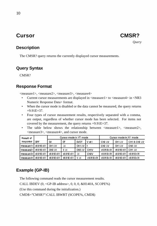
10
Cursor CMSR? Query
Description
The CMSR? query returns the currently displayed cursor measurements.
Query Syntax
CMSR?
Response Format
<measure1>, <measure2>, <measure3>, <measure4> • Current cursor measurements are displayed in <measure1> to <measure4> in <NR3
Numeric Response Data> format. • When the cursor mode is disabled or the data cannot be measured, the query returns
+9.91E+37. • Four types of cursor measurement results, respectively separated with a comma,
are output, regardless of whether cursor mode has been selected. For items not covered by the measurement, the query returns +9.91E+37.
• The table below shows the relationship between <measure1>, <measure2>, <measure3>, <measure4>, and cursor mode.
Example (GP-IB)
The following command reads the cursor measurement results.
CALL IBDEV (0, <GP-IB address>, 0, 0, 0, &H140A, SCOPE%)
(Use this command during the initialization.)
CMD$=”CMSR?”:CALL IBWRT (SCOPE%, CMD$)

11
CALL IBRD (SCOPE%, RD$): PRINT RD$

12
The response messages are as follows (in DV cursor mode)
+1.00E+0, 1.00E+0, +9.91E+37, 9.91E+37
Related Commands
CURM, VCUR, HCUR

13
Hard Copy COPY Command
Description
The COPY command copies the data to the internal printer. The Device menu item should be set to "PRINTER" and the Source menu item should be automatically set to "SCREEN". (When different settings have been provided, these menu items are changed to the above settings upon reception of remote command.)
Note: This command does not support the multi-command.
Command Syntax
COPY
Notes: - An error during the copy procedure causes a command execution error.
- The roll print is not available. Even if the COPY command is executed within the roll-printable range (5 to 50 s/div), normal printing is executed.
Example (GP-IB)
The following command copies the data to the internal printer.
CALL IBDEV (0, <GP-IB address>, 0, 0, 0, &H140A, SCOPE%)
(Use this command during the initialization.)
CMD$=”COPY”:CALL IBWRT (SCOPE%, CMD$)
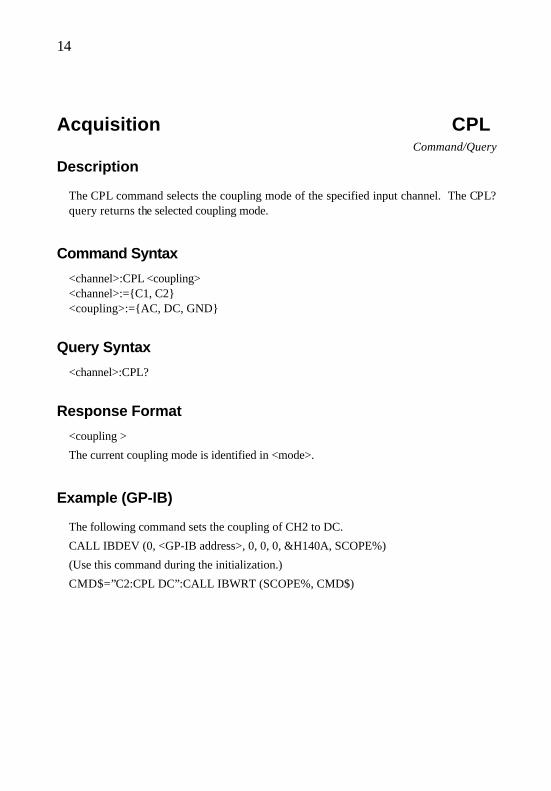
14
Acquisition CPL Command/Query
Description
The CPL command selects the coupling mode of the specified input channel. The CPL? query returns the selected coupling mode.
Command Syntax
<channel>:CPL <coupling> <channel>:=C1, C2 <coupling>:=AC, DC, GND
Query Syntax
<channel>:CPL?
Response Format
<coupling >
The current coupling mode is identified in <mode>.
Example (GP-IB)
The following command sets the coupling of CH2 to DC.
CALL IBDEV (0, <GP-IB address>, 0, 0, 0, &H140A, SCOPE%)
(Use this command during the initialization.)
CMD$=”C2:CPL DC”:CALL IBWRT (SCOPE%, CMD$)
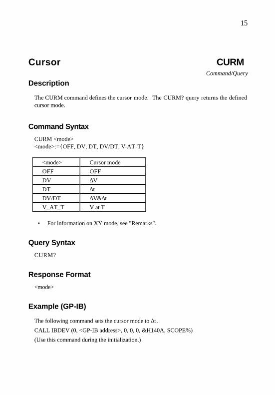
15
Cursor CURM Command/Query
Description
The CURM command defines the cursor mode. The CURM? query returns the defined cursor mode.
Command Syntax
CURM <mode> <mode>:=OFF, DV, DT, DV/DT, V-AT-T
<mode> Cursor mode
OFF OFF
DV ∆V
DT ∆t
DV/DT ∆V&∆t
V_AT_T V at T
• For information on XY mode, see "Remarks".
Query Syntax
CURM?
Response Format
<mode>
Example (GP-IB)
The following command sets the cursor mode to ∆t.
CALL IBDEV (0, <GP-IB address>, 0, 0, 0, &H140A, SCOPE%)
(Use this command during the initialization.)

16
CMD$=”CURM DT”:CALL IBWRT (SCOPE%, CMD$)

17
Related Commands
HCUR, VCUR, CMSR?
Remark
In XY mode, the command is set as follows.
<mode> XY mode
OFF OFF
DV CH2 ∆V
DT CH1 ∆V
DV/DT CH1 & CH2 ∆V
V_AT_T CH1 & CH2 ∆V

18
System DATE Command/Query
Description
The DATE command defines the date and time. The DATE? query reads the defined date and time.
Command Syntax
DATE <date>, <month>, <year>, <hour>, <min> <date>:=1∼31 <month>:=1∼12 <year>:=0∼99 <hour>:=0∼23 <min>:=0∼59
• All items are described in the format of <NR1 Numeric Response Data>. • The <year> setting defines the following
99 : 1999 0 to 98 : 2000 to 2098
Query Syntax
DATE?
Response Format
The response format is defined as follows, depending on the type of language.
Languages other than English:<year>-<month>-<date> <hour>:<min>:<sec> English:<date>-<month>-<year> <hour>:<min>:<sec> <year>: 4 digits <month>: 2 digits (three-letter abbreviation in English mode) <date>: 2 digits <hour>: 2 digits <min>: 2 digits <sec>: 2 digits

19

20
Example (GP-IB)
The following command sets the date to 11:17 of February 22, 2000.
CALL IBDEV (0, <GP-IB address>, 0, 0, 0, &H140A, SCOPE%)
(Use this command during the initialization.)
CMD$=”DATE 22, 2, 0, 11, 17”:CALL IBWRT (SCOPE%, CMD$)
Related Command
STAT

21
Automatic Measurement DIRM Command/Query
Description
The DIRM command selects the direction of automatic measurement from A, B, C, and D. To implement automatic measurement using any of the following commands, the direction must be selected using the DIRM command before the operation.
MSEL/MSE?/MCMD/MCMD?/LEVL/LEVL?/SKLV/SKLV?
The DIRM? query returns the currently selected direction.
Command Syntax
DIRM <dir> <dir>:=A, B, C, D
Query Syntax
DIRM?
Response Format
<dir>
The current direction status of the automatic measurement, A, B, C, or D, is identified in <dir>.
Example (GP-IB)
The following command selects B as the direction of automatic measurement.
CALL IBDEV (0, <GP-IB address>, 0, 0, 0, &H140A, SCOPE%)
(Use this command during the initialization.)
CMD$=”DIRM B”:CALL IBWRT (SCOPE%, CMD$)

22
Related Commands
MSEL, MCND, LEVL, SKLV

23
Data Transfer DTBORD Command/Query
Description
The DTBORD command defines the order of bytes for the waveform data transfer. The waveform transfer format should be set to "WORD". (ASCII and BYTE are invalid.) The DTWAVE? query transfers the waveform data. The DTBORD? query returns the defined byte order.
Command Syntax
DTBORD <form> <form>:=H/L, L/H
<form> Description
H/L Transfers the data in order of upper to lower bytes. L/H Transfers the data in order of lower to upper bytes.
Query Syntax
DTBORD?
Response Format
<form>
The byte order for the waveform data transfer is identified in <form>.
Example (GP-IB)
The following command sets the byte order for the waveform data transfer to H/L.
CALL IBDEV (0, <GP-IB address>, 0, 0, 0, &H140A, SCOPE%)
(Use this command during the initialization.)
CMD$=”DTBORD H/L”:CALL IBWRT (SCOPE%, CMD$)

24
Related Commands
WAVESRC, DTFORM, DTSTART, DTPOINTS, DTWAVE?
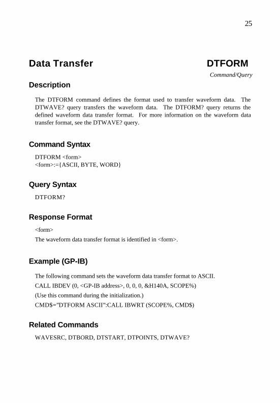
25
Data Transfer DTFORM Command/Query
Description
The DTFORM command defines the format used to transfer waveform data. The DTWAVE? query transfers the waveform data. The DTFORM? query returns the defined waveform data transfer format. For more information on the waveform data transfer format, see the DTWAVE? query.
Command Syntax
DTFORM <form> <form>:=ASCII, BYTE, WORD
Query Syntax
DTFORM?
Response Format
<form>
The waveform data transfer format is identified in <form>.
Example (GP-IB)
The following command sets the waveform data transfer format to ASCII.
CALL IBDEV (0, <GP-IB address>, 0, 0, 0, &H140A, SCOPE%)
(Use this command during the initialization.)
CMD$=”DTFORM ASCII”:CALL IBWRT (SCOPE%, CMD$)
Related Commands
WAVESRC, DTBORD, DTSTART, DTPOINTS, DTWAVE?

26
Display DTJN Command/Query
Description
The DTJN command defines the interpolation between data points. The DTJN? query returns the defined interpolation.
Command Syntax
DTJN <state> <state>:ON, OFF
Query Syntax
DTJN?
Response Format
<state>
The current interpolation between data points is identified in <state>.
Example (GP-IB)
The following command disables the interpolated line.
CALL IBDEV (0, <GP-IB address>, 0, 0, 0, &H140A, SCOPE%)
(Use this command during the initialization.)
CMD$=”DTJN OFF”:CALL IBWRT (SCOPE%, CMD$)
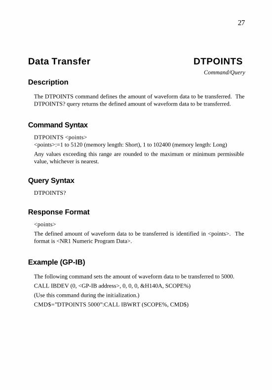
27
Data Transfer DTPOINTS Command/Query
Description
The DTPOINTS command defines the amount of waveform data to be transferred. The DTPOINTS? query returns the defined amount of waveform data to be transferred.
Command Syntax
DTPOINTS <points> <points>:=1 to 5120 (memory length: Short), 1 to 102400 (memory length: Long)
Any values exceeding this range are rounded to the maximum or minimum permissible value, whichever is nearest.
Query Syntax
DTPOINTS?
Response Format
<points>
The defined amount of waveform data to be transferred is identified in <points>. The format is <NR1 Numeric Program Data>.
Example (GP-IB)
The following command sets the amount of waveform data to be transferred to 5000.
CALL IBDEV (0, <GP-IB address>, 0, 0, 0, &H140A, SCOPE%)
(Use this command during the initialization.)
CMD$=”DTPOINTS 5000”:CALL IBWRT (SCOPE%, CMD$)

28
Remark
(Transfer start address) + (Amount of data to be transferred) > (Total amount of waveform data)
In the above case, the transfer start address is rounded to a permissible value.

29
Related Commands
WAVESRC, DTFORM, DTBORD, DTSTART, DTWAVE?

30
Data Transfer DTSTART Command/Query
Description
The DTSTART command defines the transfer start address for waveform data transfer. The DTSTART? query returns the defined transfer start address.
Command Syntax
DTSTART <start> <start>:=0 to 5119 (memory length: Short), 0 to 102399 (memory length: Long)
Any values exceeding this range are rounded to the maximum or minimum permissible value, whichever is nearest.
Query Syntax
DTSTART?
Response Format
<start>
The defined start address for waveform data transfer is identified in <start>. The format is <NR1 Numeric Program Data>.
Example (GP-IB)
The following command sets the waveform data transfer start address to 120.
CALL IBDEV (0, <GP-IB address>, 0, 0, 0, &H140A, SCOPE%)
(Use this command during the initialization.)
CMD$=”DTSTART 120”:CALL IBWRT (SCOPE%, CMD$)

31
Remark
(Transfer start address) + (Amount of data to be transferred) > (Total amount of waveform data)
In the above case, the transfer start address is rounded to a permissible value.
Related Commands
WAVESRC, DTFORM, DTBORD, DTPOINTS, DTWAVE?

32
Data Transfer DTSTUP Command/Query
Description
The DTSTUP command writes setup data for the product. The DTSTUP? query transfers the setup data (the setup data found when the query is issued) from the product. To execute the DTSTUP command and DTSTUP? query in RS-232C remote control mode, the data length should always be set to 8 bits.
Command Syntax
DTSTUP #8 <byte-length> <binary-block> • The contents of <byte_length> consists of an 8-digit ASCII string. This string
must represent the number of bytes to be entered into <binary_block>. The byte length should always be a sign-free, 8-digit integer, and zero must not be deleted.
• The data transferred by the DTSTUP? query should be found in <binary_block>.
Query Syntax
DTSTUP?
Response Format
#8 <byte-length> <binary-block> • #8 shows that the response message is described in the format of <Definite Length
Arbitrary Block Response Data> and the content of the following <byte_length> is a sign-free, 8-digit integer.
• The contents of <byte_length> represents the number of bytes to be entered into <binary_block>. The byte length should always be a sign-free, 8-digit integer including zero.
• The contents of <binary_block> represent the product's setup data in binary code.

33
Example (GP-IB)
The following command stores the setup data to file SETUP.DAT.
CALL IBDEV (0, <GP-IB address>, 0, 0, 0, &H140A, SCOPE%)
Provide a setting such that the CALL IBEOS (SCOPE%, &H1000)' input will not be incomplete at EOS.
FILE$=”SETUP1.DAT” CMD$=”DTSTUP?” CALL IBWRT (SCOPE%, CMD$) CALL IBRDF (SCOPE%, FILE$)
Provide a setting such that the CALL IBEOS (SCOPE%, &H140A)' input will be completed at EOS.

34
Data Transfer DTWAVE? Query
Description
The DTWAVE? query transfers the waveform data. The waveform data to be transferred is determined by the setting of the WAVSRC command, which defines the direction of the waveform data. To execute the binary transfer with the DTWAVE? query in RS-232C remote control mode, the data length should always be set to 8 bits.
Query Syntax
DTWAVE?
Response Format
The following response formats are created according to the settings of the DTFORM and DTBOARD commands.
(1) The DTFORM command is set to "BYTE/WORD" (binary transfer):
#8 <byte-length> <binary-block> • #8 shows that the response message is described in the format of <Definite
Length Arbitrary Block Response Data> and that the content of the following <byte_length> is an 8-digit ASCII string.
• The contents of <byte_length> represents the number of bytes to be entered into <binary_block>. The byte length should always be a sign-free, 8-digit integer including zero.
• The contents of <binary_block> represents the waveform data stored in the product's internal memory in binary code.
[Example of data]
# 8 0 0 0 0 5 1 2 0 D0 D1 - - - Dn
5120-byte binary data (D0, D1,..., Dn) is transferred.
(a) The DTFORM command is set to "BYTE":

35
• Since one unit of data is transferred in one byte, the number of bytes agree with the number of transfer data units specified using the DTPOINTS command.

36
[Example of data]
# 8 0 0 0 0 5 1 2 0 D0 D1 - - - Dn
5120-byte binary data is transferred, and Di (i = 1, 2,..., n) corresponds to one unit of data.
Note: For average waveforms, only upper bytes are transferred, even though these waveforms are word data.
(b) The DTFORM command is set to "WORD":
• Since one unit of data is transferred in two bytes, the number of bytes to be transferred is twice as large as the number of transfer data units specified with the DTPOINTS command.
[Example of data]
# 8 0 0 1 0 2 4 0 U0 L0 U1 L1 - - - Un Ln
• 10240-byte binary data (U0, L0, U1, L1,..., Un, Ln) is transferred. • Two bytes Ui and Li (i = 1, 2,..., n) correspond to one unit of data. • For average waveforms, two bytes, Ui and Li (i = 1, 2,..., n) are both
enabled. For other waveforms, Li (i = 1, 2,..., n) is 0. • The DTBORD command is used to specify the byte order. When L/H is
specified, the data is transferred in the order of Li, Ui (i = 1, 2,..., n).
(2) The DTFORM command is set to "ASCII":
<ascii_block> <delimiter> • <ascii_block> contains block data. The waveform data units stored in the
product's internal memory are described in the format of <NR1 Numeric Program Data> one by one, and these data units are respectively separated by a comma.
• When the waveform data is not for an average waveform, the value is 256 times as large as that of average waveform data. When the waveform data is average waveform data, the raw data is used as is.
[Example of data]
D0, D1,..., Dn)
Di (i = 0, 1,..., n) is described in the format of <NR1 Numeric Program Data>.

37
Example (GP-IB)
The following command transfers the 5120-byte waveform data on CH1, starting from the start address, and stores the data to file WAVE1.DAT.
CALL IBDEV (0, <GP-IB address>, 0, 0, 0, &H140A, SCOPE%)
(Use this command during the initialization.)
CMD$= ”DTSTART 0” CALL IBWRT (SCOPE%, CMD$) CMD$= ”DTPOINTS 5120” CALL IBWRT (SCOPE%, CMD$) CMD$= ”DTFORM BYTE” CALL IBWRT (SCOPE%, CMD$) CALL IBEOS (SCOPE%, &H1000) FILE$= ”WAVE1.DAT” CMD$= ”DTWAVE” CALL IBWRT (SCOPE%, CMD$) CALL IBRDF (SCOPE%, FILE$) CALL IBEOS (SCOPE%, &H140A)
Related Commands
WAVESRC, DTFORM, DTBORD, DTSTART, DTPOINTS

38
Acquisition EQU Command/Query
Description
The EQU command enables or disables the equivalent sample. The EQU? query returns the enabled or disabled equivalent sample status.
Command Syntax
EQU <mode> <mode>:=ON, OFF
Query Syntax
EQU?
Response Format
<mode>
The currently set equivalent sample is identified in <mode>.
Example (GP-IB)
The following command enables the equivalent sample.
CALL IBDEV (0, <GP-IB address>, 0, 0, 0, &H140A, SCOPE%)
(Use this command during the initialization.)
CMD$=”EQU ON”:CALL IBWRT (SCOPE%, CMD$)
Related Commands
TDIV, MLEN

39
Status *ESE Command/Query
Description
The *ESE command defines the standard event status enable (ESE) register. This command allows the user to connect multiple events in the ESR register to the ESB summary message bit (bit 5) of the STB register. The *ESE? query reads the contents of the ESE register.
Command Syntax
*ESE <value> <value>:=0∼255
Query Syntax
*ESE?
Response Format
<value>
The current contents of the ESE register are identified in <value>. The format is <NR1 Numeric Response Data>.
Example (GP-IB)
The following command configures the ESB bit when a command error (EXE bit 4, i.e., 16 of decimal number) occurs and/or an execution error (CME bit 5, i.e., 32 of decimal number) occurs. The sum of these values is masked by the ESE register and becomes 48 (i.e., 32 + 16).
CALL IBDEV (0, <GP-IB address>, 0, 0, 0, &H140A, SCOPE%)
(Use this command during the initialization.)
CMD$=”*ese 48”:CALL IBWRT (SCOPE%, CMD$)

40
Related Command
*ESR

41
Status *ESR? Query
Description
The *ESR? query reads and clears the event status register (ESR). The binary codes in register bits 0 and 7 are added together, and the sum is returned as a response to this query. The structure of the ESR register is outlined in "Remarks".
Query Syntax
*ESR?
Response Format
<value>
The current contents of the ESR register are identified in <value>. The format is <NR1 Numeric Response Data>.
Example (GP-IB)
The following statement reads and clears the contents of the ESR register.
CALL IBDEV (0, <GP-IB address>, 0, 0, 0, &H140A, SCOPE%)
(Use this command during the initialization.)
CMD$=”*ESR?”:CALL IBWRT (SCOPE%, CMD$) CALL IBRD (SCOPE%, RSP$):PRINT RSP$ Response message: +00000

42
Remark
The table below shows the structure of the ESR register.
Bit Weighting Description
7 128 PON: Power-on
6 64 URQ: This bit is not used in this product.
5 32 CME: Command error
4 16 EXE: Execution error
3 8 DDE: Device-specific error
2 4 QYE: Query error
1 2 RQC: This bit is not used in this product.
0 1 OPC: Operation complete
Related Commands
*CLS, *ESE
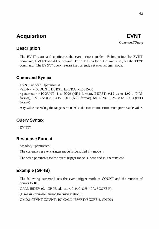
43
Acquisition EVNT Command/Query
Description
The EVNT command configures the event trigger mode. Before using the EVNT command, EVENT should be defined. For details on the setup procedure, see the TTYP command. The EVNT? query returns the currently set event trigger mode.
Command Syntax
EVNT <mode>, <parameter> <mode>:= COUNT, BURST, EXTRA, MISSING <parameter>:=COUNT: 1 to 9999 (NR1 format), BURST: 0.15 µs to 1.00 s (NR3 format), EXTRA: 0.20 µs to 1.00 s (NR3 format), MISSING: 0.25 µs to 1.00 s (NR3 format)
Any value exceeding the range is rounded to the maximum or minimum permissible value.
Query Syntax
EVNT?
Response Format
<mode>, <parameter>
The currently set event trigger mode is identified in <mode>.
The setup parameter for the event trigger mode is identified in <parameter>.
Example (GP-IB)
The following command sets the event trigger mode to COUNT and the number of counts to 10.
CALL IBDEV (0, <GP-IB address>, 0, 0, 0, &H140A, SCOPE%)
(Use this command during the initialization.)
CMD$=”EVNT COUNT, 10”:CALL IBWRT (SCOPE%, CMD$)

44

45
Related Command
TTYP

46
Cursor HCUR Command/Query
Description
The HCUR command defines the position of the time cursor in "div". The HCUR? query returns the defined position of the time cursor.
Command Syntax
HCUR <Cursor1>, HCUR <Cursor2> <Cursor1>:=-5.00∼+5.00 <Cursor2>:=-5.00∼+5.00
<Cursor1> and <Cursor2> respectively represent positions of time cursors H-C1 and H-C2 on the screen, using the unit, "div". For how to round the value, see "Remarks". The left end of the screen corresponds to -5.00, the center to 0, and the right end to +5.00.
Query Syntax
HCUR?
Response Format
<Cursor1>, <Cursor2>
Current positions of the time cursors are identified in <Cursor1> and <Cursor2>. The format is <NR3 Numeric Response Data>.
Example (GP-IB)
The following command sets the time cursors H-C1 and H-C2 to -1 div and +2 div, respectively.
CALL IBDEV (0, <GP-IB address>, 0, 0, 0, &H140A, SCOPE%)
(Use this command during the initialization.)
CMD$=”HCUR –1, +2”:CALL IBWRT (SCOPE%, CMD$)

47
Related Commands
CURM, VCUR, CMSR?
Remark
Any value exceeding the range of <Cursor1> and <Cursor2> is rounded to the maximum or minimum permissible value.
• The resolution of <Cursor1> and <Cursor2> is 0.04. If another value is input, it is rounded to a number having a small absolute value.
• If the cursor mode is set to "V at T", the setting of <Cursor1> is enabled. Although <Cursor2> is disabled, you should still set it.
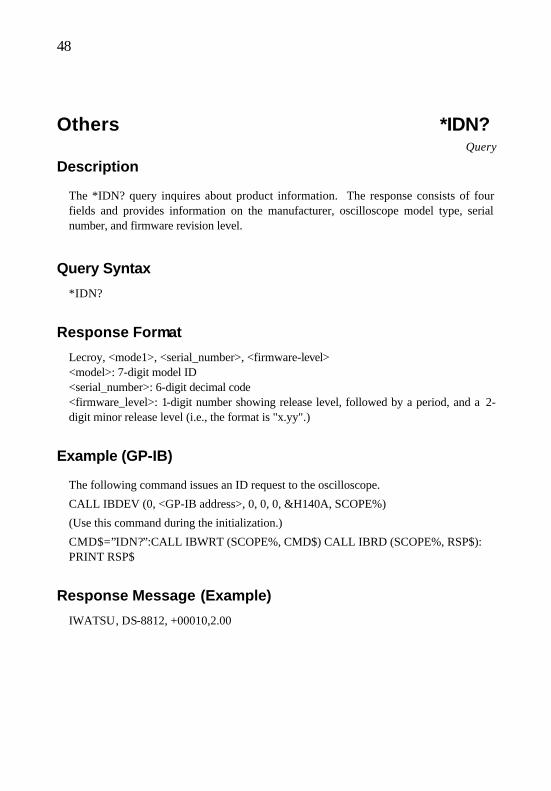
48
Others *IDN? Query
Description
The *IDN? query inquires about product information. The response consists of four fields and provides information on the manufacturer, oscilloscope model type, serial number, and firmware revision level.
Query Syntax
*IDN?
Response Format
Lecroy, <mode1>, <serial_number>, <firmware-level> <model>: 7-digit model ID <serial_number>: 6-digit decimal code <firmware_level>: 1-digit number showing release level, followed by a period, and a 2-digit minor release level (i.e., the format is "x.yy".)
Example (GP-IB)
The following command issues an ID request to the oscilloscope.
CALL IBDEV (0, <GP-IB address>, 0, 0, 0, &H140A, SCOPE%)
(Use this command during the initialization.)
CMD$=”IDN?”:CALL IBWRT (SCOPE%, CMD$) CALL IBRD (SCOPE%, RSP$): PRINT RSP$
Response Message (Example)
IWATSU, DS-8812, +00010,2.00

49
Automatic Measurement LEVL Command/Query
Description
The LEVL command defines the measurement conditions for automatic measurement items, FREQ, PERIOD, +PW, -PW, and DUTY, which are selected using the MSEL command. The LEVL? query returns the defined measurement conditions.
Command Syntax
LEVL <level>
The value ranging from 10 to 90 is input to <level>. The format is <NR1 Numeric Program Data>.
Any value exceeding the range is rounded to the maximum or minimum permissible value.
Query Syntax
LEVL?
Response Format
<level>
The parameter setup level for automatic measurement items, FREQ, PERIOD, +PW, -PW, and DUTY, is identified in <level>.
Example (GP-IB)
The following command sets the measurement item of automatic measurement B to +PW of CH2 and the measurement parameter to 20%.
CALL IBDEV (0, <GP-IB address>, 0, 0, 0, &H140A, SCOPE%)
(Use this command during the initialization.)
CDM$= ”DIRM B”: CALL IBWRT (SCOPE%, CMD$) CDM$= ”MSEL CH2, +PW”: CALL IBWRT (SCOPE%, CMD$) CDM$= ”LEVL 20”: CALL IBWRT (SCOPE%, CMD$)

50

51
Related Commands
DIRM, MSEL

52
Display MATH Command/Query
Description
The MATH command defines the type of mathematical operation for waveforms. The MATH? query returns the defined mathematical operation type.
Command Syntax
MATH <mode> <mode>:=OFF, ADD, SUB, MULT
Query Syntax
MATH?
Response Format
<mode>
The currently defined mathematical operation type is identified in <mode>.
Example (GP-IB)
The following command sets the mathematical operation type to ADD.
CALL IBDEV (0, <GP-IB address>, 0, 0, 0, &H140A, SCOPE%)
(Use this command during the initialization.)
CMD$=”MATH ADD”:CALL IBWRT (SCOPE%, CMD$)
Related Command
TRA

53
Remark
• Only in mathematical operation display mode, both CH1 and CH2 traces can be set to "OFF" using the TRA command.
• The relevant waveforms are not displayed while the ROLL command is in effect. They will be displayed after a STOP command is issued.

54
Automatic Measurement MCND Command/Query
Description
The MCND command defines the measurement conditions for automatic measurement items, TR and TF, which are selected using the MSEL command. The MCND? query returns the defined measurement conditions.
Command Syntax
MCND <base>, <upper level>, <lower level> <base>:=T-B, P-P
<base> Contents
T-B T-B: Top-Base is selected. P-P P-P: P-P is selected.
A value ranging from 11 to 90 is input to <upper level> in <NR1 Numeric Program Data> format. Any values exceeding this range are rounded to the maximum or minimum permissible value, whichever is nearest.
A value ranging from 10 to 89 is input to <lower level> in <NR1 Numeric Program Data> format. Any values exceeding this range are rounded to the maximum or minimum permissible value, whichever is nearest.
Query Syntax
MCND?
Response Format
<base>, <upper level>, <lower level>
The 100% parameter setup level is identified in <base> for the automatic measurement items, TR and TF.
The upper level is identified in <upper level > for the automatic measurement items, TR and TF.

55
The lower level is identified in <lower level > for the automatic measurement items, TR and TF.

56
Example (GP-IB)
The following command sets the measurement item of automatic measurement B to TR of CH2, and sets the measurement parameters Top-Base to 100%, Upper Level to 80%, and Lower Level to 20%.
CALL IBDEV (0, <GP-IB address>, 0, 0, 0, &H140A, SCOPE%)
(Use this command during the initialization.)
CMD$=”DIRM B”:CALL IBWRT (SCOPE%, CMD$) CMD$=”MSEL CH2, TR”:CALL IBWRT (SCOPE%, CMD$) CMD$=”MCND T-B, 80, 20”:CALL IBWRT (SCOPE%, CMD$)
Related Commands
DIRM, MSEL
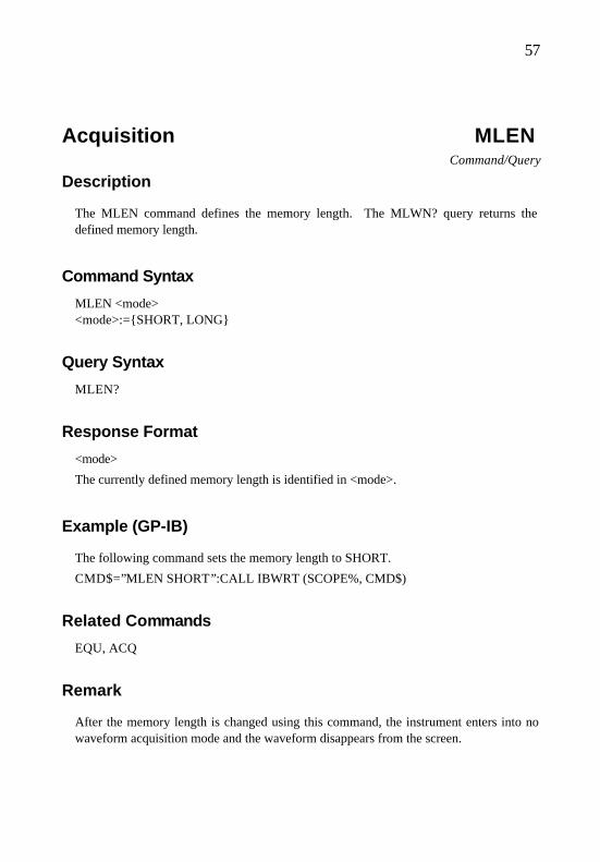
57
Acquisition MLEN Command/Query
Description
The MLEN command defines the memory length. The MLWN? query returns the defined memory length.
Command Syntax
MLEN <mode> <mode>:=SHORT, LONG
Query Syntax
MLEN?
Response Format
<mode>
The currently defined memory length is identified in <mode>.
Example (GP-IB)
The following command sets the memory length to SHORT.
CMD$=”MLEN SHORT”:CALL IBWRT (SCOPE%, CMD$)
Related Commands
EQU, ACQ
Remark
After the memory length is changed using this command, the instrument enters into no waveform acquisition mode and the waveform disappears from the screen.

58

59
Automatic Measurement MSEL Command/Query
Description
The MSEL command selects the measurement item of automatic measurement A, B, C, or D defined using the automatic measurement direction command DIRM. The MSEL? Query returns the selected measurement item.
Command Syntax
MSEL, <ch>, <mode> <ch>:= CH1, CH2, CH1&2 <mode>:= TR, TE, VRMS, VMEAN, FREQ, PERIOD, +PW, -PW, DUTY, +PEAK, -PEAK, P-P, SKEW
For the combination and meaning of set items in <ch> and <mode>, see "Supplementary Information".
Query Syntax
MSEL?
Response Format
<ch>, <mode>
The selected automatic measurement channel is identified in <ch>.
The automatic measurement item is identified in <mode>.
Example (GP-IB)
The following command sets the measurement item of automatic measurement B to TR of CH2.
CALL IBDEV (0, <GP-IB address>, 0, 0, 0, &H140A, SCOPE%)
(Use this command during the initialization.)
CMD$=”DIRM B”:CALL IBWRT (SCOPE%, CMD$)

60
CMD$=”MSEL CH2, TR”:CALL IBWRT (SCOPE%, CMD$)

61
Related Commands
DIRM, MCND, LEVL, SKLV
Supplementary Information
• The table below shows the combination and meaning of set items in <ch> and <mode>.
<ch> <mode> Description
CH or CH2 or CH1&2 (*1) OFF Automatic measurement disabled CH or CH2 (*2) TR Rise measurement CH or CH2 (*2) TF Fall measurement CH or CH2 (*2) VRMS Root mean square value (RMS) CH or CH2 (*2) VMEAN Average CH or CH2 (*2) FREQ Frequency CH or CH2 (*2) PERIOD Period CH or CH2 (*2) +PW Positive pulse width CH or CH2 (*2) -PW Negative pulse width CH or CH2 (*2) DUTY Duty ratio CH or CH2 (*2) +PEAK Maximum CH or CH2 (*2) -PEAK Minimum CH or CH2 (*2) P-P Difference between maximum and minimum CH or CH2 or CH1&2 (*1) SKEW Time difference between CH1 and CH2
Notes: (*1): The MSEL? query returns a response in the form of CH1&2. (*2): CH1 & 2, when provided, is set in the form of CH1.
• To assign a positive mark "+" to the automatic measuring point, set the reference waveform display to "OFF" and the status display to "MEASURE".

62
Automatic Measurement MSRA?, MSRB?, MSRC?, MSRD?
Query
Description
MSRA?, MSRB?, MSRC?, and MSRD? queries respectively read automatic measurements A, B, C, and D.
Query Syntax
MSRA? (or MSRB?, MSRC?, or MSRD?)
Response Format
<measure>
The result of automatic measurement A (or B, C, or D) is identified in <measure>. The indicated value is converted into <NR3 Numeric Program Data> and returned. If automatic measurement is not possible, +9.91E+37 is returned.
Example (GP-IB)
The following command reads the result of automatic measurement A.
CALL IBDEV (0, <GP-IB address>, 0, 0, 0, &H140A, SCOPE%)
(Use this command during the initialization.)
CMD$=”MSRA?”:CALL IBWRT (SCOPE%, CMD$) CALL IBRD (SCOPE%, MESA$):PRINT MESA$
Response Message
+1.23E+4

63
Acquisition OFST Command/Query
Description
The OFST command defines the vertical position (offset) of the specified input channel. The setting range depends on the vertical sensitivity. The OFST? query returns the defined vertical position (offset).
Command Syntax
<channel>:OFST <offset> <channel1>:=C1, C2
<offset>:= Offset voltage. The <Numeric Program Data> format is basically used in <offset>, and the suffix is also valid. For the setting range and rounding rule, see "Remarks".
Note: The suffix, V, is optional.
Query Syntax
<channel>:OFST?
Response Format
<offset>
The current offset is identified in <offset> in <NR1 Numeric Program Data> format.
Example (GP-IB)
The following command sets the offset of channel 2 to -3 V.
CALL IBDEV (0, <GP-IB address>, 0, 0, 0, &H140A, SCOPE%)
(Use this command during the initialization.)
CMD$=”C2:OFST-3V”:CALL IBWRT (SCOPE%, CMD$)
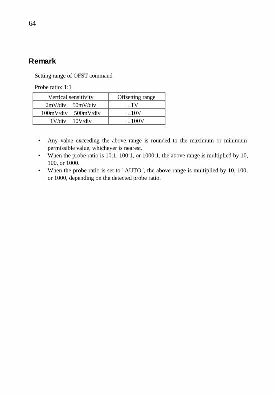
64
Remark
Setting range of OFST command
Probe ratio: 1:1
Vertical sensitivity Offsetting range 2mV/div ∼ 50mV/div ±1V
100mV/div ∼ 500mV/div ±10V 1V/div ∼ 10V/div ±100V
• Any value exceeding the above range is rounded to the maximum or minimum permissible value, whichever is nearest.
• When the probe ratio is 10:1, 100:1, or 1000:1, the above range is multiplied by 10, 100, or 1000.
• When the probe ratio is set to "AUTO", the above range is multiplied by 10, 100, or 1000, depending on the detected probe ratio.

65
Status *OPC Command/Query
Description
The *OPC (Operation Complete) command sets the OPT bit (bit 0) of the standard event status register (ESR) to "TRUE" when all the preceding operations are completed. Since the *OPC? query issues the response after execution of all preceding commands, ASCII code "1" is returned. If all commands are not completed, "0" is returned. For the *OPC? query, the OPT bit (bit 0) of the ESR register is not affected by other operations.
Note: The OPC command does not support the malti-command.
Command Syntax
*OPC
Query Syntax
*OPC?
Response Format
+00001 or +00000
Related Command
*WAI

66
Display PERS Command/Query
Description
The PERS command enables or disables persistence display mode. The PERS? query returns the current status of the persistence display mode.
Command Syntax
PERS <mode> <mode>:=ON, OFF
Query Syntax
PERS?
Response Format
<mode>
The current persistence display mode is identified in <mode>.
Example (GP-IB)
The following command enables persistence display mode.
CALL IBDEV (0, <GP-IB address>, 0, 0, 0, &H140A, SCOPE%)
(Use this command during the initialization.)
CMD$=”PERS ON”:CALL IBWRT (SCOPE%, CMD$)
67
Acquisition PROBE Command/Query
Description
The PROBE command selects the probe ratio of the specified input channel. AUTO, 1, 10, 100, or 1000 can be selected. The PROBE? query returns the selected probe ratio.
Command Syntax
<channel>: PROBE <probe_mode>, <probe> <channel>: = C1, C2 <probe_mode>: = AUTO, MANUAL <probe>: = 1, 10, 100, 1000
For the combination and meaning of set items in <probe_mode> and <probe>, see "Remarks".
Query Syntax
<channel>:=PROBE?
Response Format
• When the probe ratio is 1:1, 10:1, 100:1, or 1000:1, a value equal to the PROBE command parameter is returned.
• When the probe ratio is set to "AUTO", the detected ratio is returned to <probe>.
Notes: When the probe ratio is set to "AUTO", "1000:1" is undetected.
Example (GP-IB)
The following command sets the probe ratio of channel 1 to 100.
CALL IBDEV (0, <GP-IB address>, 0, 0, 0, &H140A, SCOPE%)
(Use this command during the initialization.)
CMD$= “C1:PROBE MANUAL, 100”: CALL IBWRT (SCOPE%, CMD$)

68
Remark
The table below shows settings for <probe_mode> and <probe>.
Set probe ratio <probe_mode> <probe>
AUTO 1:1 10:1 100:1 1000:1
AUTO MANUAL MANUAL MANUAL MANUAL
1/10/100/1000 1 10 100 1000

69
Save/Recall *RCL Command
Description
The *RCL command recalls all the front panel setup data from the oscilloscope and defines the state of the oscilloscope using one of ten nonvolatile panel setup data sets. The *RCL command provides a function contrary to the *SAV command.
Command Syntax
*RCL <panel_setup> <panel_setup>:1∼10
1: The data is recalled from the Setup Save/Undo area of the product.
2 to 10: The data is recalled from the product's specified remote area.
Any value exceeding the range is rounded to the maximum or minimum permissible value..
Note: In local mode, the data cannot be recalled from areas 2 to 10.
Example (GP-IB)
The following command recalls the oscilloscope setup data stored to panel setup 3.
CALL IBDEV (0, <GP-IB address>, 0, 0, 0, &H140A, SCOPE%)
(Use this command during the initialization.)
CMD$=”*RCL3”:CALL IBWRT (SCOPE%, CMD$)
Related Command
*SAV

70
Save/Recall REFCLR Command/Query
Description
The REFCLR command deletes all the displayed reference waveforms. (The data stored in memory is not deleted.)
Command Syntax
REFCLR
Example (GP-IB)
The following command deletes all the displayed reference waveforms.
CALL IBDEV (0, <GP-IB address>, 0, 0, 0, &H140A, SCOPE%)
(Use this command during the initialization.)
CMD$=”REFCLR”:CALL IBWRT (SCOPE%, CMD$)
Related Commands
REFSAV, REFRCL

71
Save/Recall REFRCL Command
Description
The REFRCL command recalls from internal memory the stored reference waveforms, as well as the setups that were effective when the waveforms were stored. For execution error conditions, see "Supplementary Information".
Note: The REFRCL command does not support the multi-command.
Command Syntax
REFRCL <fileno>, <mode> <fileno>:= 1 to 5 (described in <NR1 Numeric Program Data>) Any value exceeding the range is rounded to the maximum or minimum permissible value. <mode>:=REF, SETUP, BOTH
<mode> Description
REF Recalls the reference waveforms specified in <fileno>.
SETUP Recalls the setups that were effective when the reference waveforms specified in <fileno> were stored.
BOTH Executes the contents of both the REF and SETUP.
Example (GP-IB)
The following command recalls the reference waveform stored in file 3.
CALL IBDEV (0, <GP-IB address>, 0, 0, 0, &H140A, SCOPE%)
(Use this command during the initialization.)
CMD$=”REFRCL 3, REF”:CALL IBWRT (SCOPE%, CMD$)
Related Commands
REFCLR, REFSAV

72
Supplementary Information
When the REFRCL command meets either of the following conditions, an error occurs.
• A nonexistent file number is specified. • The current mode is XY mode.

73
Save/Recall REFSAV Command
Description
The REFSAV command saves in internal memory the reference waveforms and their setups in effect at the time the command was used. If the specified file number already exists, the old file is automatically overwritten. For execution error conditions, see "Supplementary Information".
Note: The REFSAV command does not support the multi-command.
Command Syntax
REFSAV <fileno>
<fileno>:= 1 to 5 (described in <NR1 Numeric Program Data>). Any values exceeding this range are rounded to the maximum or minimum permissible value, whichever is nearest.
Example (GP-IB)
The following command saves the reference waveform and its setup in file 3.
CALL IBDEV (0, <GP-IB address>, 0, 0, 0, &H140A, SCOPE%)
(Use this command during the initialization.)
CMD$=”REFSAV 3”:CALL IBWRT (SCOPE%, CMD$)
Related Commands
REFCLR, REFRCL
Supplementary Information
If the REFSAV command meets any of the following conditions, an error occurs and the reference data is cleared.
• Waveforms have not been acquired. • Both CH1 and CH2 traces are set to "OFF".

74
• The current mode is XY mode.
75
Acquisition ROLL Command/Query
Description
The ROLL command enables or disables roll operations. The ROLL? query returns the current roll operation status.
Command Syntax
ROLL <mode> <mode>:=ON, OFF
Query Syntax
ROLL?
Response Format
<mode>
The current roll operation status is identified in <mode>.
Example (GP-IB)
The following command enables roll operations.
CALL IBDEV (0, <GP-IB address>, 0, 0, 0, &H140A, SCOPE%)
(Use this command during the initialization.)
CMD$=”ROLL ON”:CALL IBWRT (SCOPE%, CMD$)
Related Command
TDIV

76
Save/Recall *RST Command
Description
The *RST command enables device reset. The *RST command recalls the default setups.
Command Syntax
*RST
Example (GP-IB)
The following command recalls the default setup.
CALL IBDEV (0, <GP-IB address>, 0, 0, 0, &H140A, SCOPE%)
(Use this command during the initialization.)
CMD$=”*RST”:CALL IBWRT (SCOPE%, CMD$)
Related Commands
*CAL, *RCL
77
Acquisition RUN Command
Description
RUN enables waveform acquisition mode. If waveform acquisition mode has already been enabled, this command is ignored. If sweep mode is set to SINGLE, the RUN command acts as a WSGL command.
Note: The RUN commands does not support the malti-command.
Command Syntax
RUN
Example (GP-IB)
The following command enables waveform acquisition mode.
CALL IBDEV (0, <GP-IB address>, 0, 0, 0, &H140A, SCOPE%)
(Use this command during the initialization.)
CMD$=”RUN”:CALL IBWRT (SCOPE%, CMD$)
Related Commands
STOP, WSGL

78
Save/Recall *SAV Command
Description
The *SAV command saves the current state of the oscilloscope to nonvolatile internal memory. The *SAV command saves all the front panel setup data of the oscilloscope.
Command Syntax
*SAV <panel_setup> <panel_setup>:=1∼10
1: The data is saved in the Setup Save/Undo area of the product.
2 to 10: The data is saved to the specified remote area of the product.
Any value exceeding the range is rounded to the maximum or minimum permissible value.
Note: In local mode, the data cannot be saved to areas 2 to 10.
Example (GP-IB)
The following command saves the current oscilloscope setup data to panel setup 3.
CALL IBDEV (0, <GP-IB address>, 0, 0, 0, &H140A, SCOPE%)
(Use this command during the initialization.)
CMD$=”*SAV 3”:CALL IBWRT (SCOPE%, CMD$)
Related Command
*RCL

79
Display SCALE Command/Query
Description
The SCALE command defines the scale. The SCALE? query returns the defined scale.
Command Syntax
SCALE <mode> <mode>: = GRID, AXIS, FRAME
Query Syntax
SCALE?
Response Format
<mode>
The currently defined scale is identified in <mode>.
Example (GP-IB)
The following command sets the scale to GRID.
CALL IBDEV (0, <GP-IB address>, 0, 0, 0, &H140A, SCOPE%)
(Use this command during the initialization.)
CMD$= “SCALE GRID”: CALL IBWRT (SCOPE%, CMD$)

80
Automatic Measurement SKLV Command/Query
Description
The SKLV command defines the measurement conditions of automatic measurement SKEW specified with the WSEL command. The SKLV? query returns the defined measurement conditions.
Command Syntax
SKLV <ch1-level>, <ch1_edge>, <ch2_level>, <ch2_edge> <ch1_edge>:=RISE, FALL <ch2_edge>:=RISE, FALL
A value ranging from 10 to 90 is input to <ch1_level> in <NR1 Numeric Program Data> format. Any values exceeding this range are rounded to the maximum or minimum permissible value, whichever is nearest.
A value ranging from 10 to 90 is input to <ch2_level> in <NR1 Numeric Program Data> format. Any values exceeding this range are rounded to the maximum or minimum permissible value, whichever is nearest.
Query Syntax
SKLV?
Response Format
<ch1_level>, <ch1_edge>, <ch2_level>, <ch2_edge>
The parameter setting "ch1 Edge" of automatic measurement SKEW is identified in <ch1_edge>.
The parameter setting "ch2 Edge" of automatic measurement SKEW is identified in <ch2_edge>.
The parameter setting "ch1 Level" of automatic measurement SKEW is identified in <ch1_level>.

81
The parameter setting "ch2 Level" of automatic measurement SKEW is identified in <ch2_level>.

82
Example (GP-IB)
The following command sets automatic measurement B to SKEW, and the measurement parameters CH1 Level to 60%, CH1 Edge to RISE, CH2 Level to 50%, and CH2 Edge to FALL.
CALL IBDEV (0, <GP-IB address>, 0, 0, 0, &H140A, SCOPE%)
(Use this command during the initialization.)
CMD$=”RUN”:CALL IBWRT (SCOPE%, CMD$) CMD$=”MSEL CH1&2, SKEW”:CALL IBWRT (SCOPE%, CMD$) CMD$=”SKLV 60, RISE, 50, FALL”:CALL IBWRT (SCOPE%, CMD$)
Related Commands
DIRM, MSEL

83
Status *SRE Command/Query
Description
The *SRE command defines the service request enable (SRE) register. This command allows the user to specify what SBT register summary bit is used to create the service request (SRQ). If "1" is written to the associated bit location, the summary message bit is enabled. If "0" is written to the associated bit location, the service request is no longer created by the associated event. After the SRE register is cleared, the SRQ interrupt is disabled. When the value is converted into binary code, the *SRE? query returns the value that represents the bit setting in the SRE register.
Command Syntax
*SRE <value> <value>:=0∼255
Query Syntax
*SRE?
Response Format
<value>
The current SRE register settings are identified in <value> in <NR1 Numeric Response Data> format.
Example (GP-IB)
The following command creates SRQ immediately after the MAV summary bit (bit 4, i.e., 16 of decimal number) or TRG summary bit (bit 0, i.e., 1 of decimal number) of the STB register, or both bits are set. Adding these two values gives SRE mask 17 (i.e., 1 + 16).
CALL IBDEV (0, <GP-IB address>, 0, 0, 0, &H140A, SCOPE%)
(Use this command during the initialization.)
CMD$=”*SRE 17”:CALL IBWRT (SCOPE%, CMD$)
84
Display STAT Command/Query
Description
The STAT command defines the status display. The STAT? query returns the defined status display.
Command Syntax
STAT <mode> <mode>:=OFF, COUNTER, DATE, MEASURE, COMMENT
Query Syntax
STAT?
Response Format
<mode>
The currently defined status display is identified in <mode>.
Example (GP-IB)
The following command sets the status display to COUNTER.
CALL IBDEV (0, <GP-IB address>, 0, 0, 0, &H140A, SCOPE%)
(Use this command during the initialization.)
CMD$=”STAT COUNTER”:CALL IBWRT (SCOPE%, CMD$)
Related Commands
DIRM, MSEL, CMNT, DATE

85
Status *STB? Query
Description
The *STB? query reads the status register (STB) defined in IEEE 488.1 and the master summary status (MSS). The response includes those values specified in bits 0 to 5 and 7 of the status byte register, as well as the MSS summary message.
The response to the *STB? query is the same as that for series polling, except that bit 6 contains the MSS summary message instead of the RQS message.
Query Syntax
*STB?
Response Format
<value>
The current STB register settings are identified in <value> in <NR1 Numeric Response Data> format.
Example (GP-IB)
The following command reads the status byte register.
CALL IBDEV (0, <GP-IB address>, 0, 0, 0, &H140A, SCOPE%)
(Use this command during the initialization.)
CMD$=”*STB?”:CALL IBWRT (SCOPE%, CMD$) CALL IBRD (SCOPE%, RSP$):PRINT RSP$ Response message: +00000
Related Commands
*CLS, *SRE
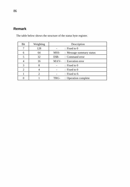
86
Remark
The table below shows the structure of the status byte register.
Bit Weighting Description
7 128 - : Fixed to 0
6 64 MSS- : Message summary status
5 32 ESB- : Command error
4 16 MAV- : Execution error
3 8 - : Fixed to 0
2 4 - : Fixed to 0
1 2 - : Fixed to 0.
0 1 TRG- : Operation complete
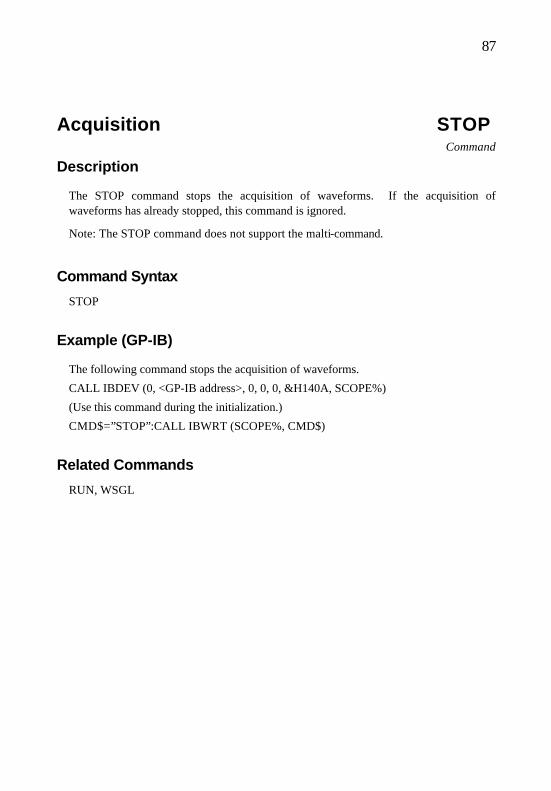
87
Acquisition STOP Command
Description
The STOP command stops the acquisition of waveforms. If the acquisition of waveforms has already stopped, this command is ignored.
Note: The STOP command does not support the malti-command.
Command Syntax
STOP
Example (GP-IB)
The following command stops the acquisition of waveforms.
CALL IBDEV (0, <GP-IB address>, 0, 0, 0, &H140A, SCOPE%)
(Use this command during the initialization.)
CMD$=”STOP”:CALL IBWRT (SCOPE%, CMD$)
Related Commands
RUN, WSGL

88
Acquisition SWMD Command/Query
Description
The SWMD command selects the sweep mode. The SWMD? query returns the currently selected sweep mode.
Command Syntax
SWMD <mode> <mode>:=AUTO, NORMAL, SINGLE
Depending on the contents of the roll operation, the following setting is input to <mode>.
• Roll is set to "OFF": AUTO, NORMAL, or SINGLE
• Roll is set to "ON" and the range enables roll operations:
Setting Roll mode
AUTO Endless
NORMAL Endless
SINGLE Trigger’d
Query Syntax
SWMD?
Response Format
<mode> • Roll is set to "OFF":
AUTO, NORMAL, or SINGLE • Roll is set to "ON" and the range enables roll operation:
ENDLESS or TRIGGER'D.

89
Example (GP-IB)
The following command selects the normal sweep mode.
CALL IBDEV (0, <GP-IB address>, 0, 0, 0, &H140A, SCOPE%)
(Use this command during the initialization.)
CMD$=”SWMD NORMAL”:CALL IBWRT (SCOPE%, CMD$)
Related Command
WSGL
Remark
• When the sweep mode is changed to SINGLE from any setting other than SINGLE or TRIGGER'D, the instrument enters STOP mode.
• If the sweep mode is set to SINGLE or TRIGGER'D and the acquisition of waveforms is completed, the single -measurement- complete bit of the trigger event status byte register is set to 1.

90
Acquisition TCPL Command/Query
Description
The TCPL command defines the trigger coupling mode. The TCPL? query returns the defined trigger coupling.
Command Syntax
TCPL <tirg_coupling> <trig_coupling>:=AC, DC, HF, LF
Query Syntax
TCPL?
Response Format
<trig_coupling>
The current trigger coupling is identified in <trig_coupling>.
Example (GP-IB)
The following command sets the coupling mode to AC.
CALL IBDEV (0, <GP-IB address>, 0, 0, 0, &H140A, SCOPE%)
(Use this command during the initialization.)
CMD$=”TCPL AC”:CALL IBWRT (SCOPE%, CMD$)
Related Commands
TTYP, TSRC

91
Remark
When the trigger type is TV and this TCPL command is used, a device-specific error occurs.

92
Acquisition TDIV Command/Query
Description
The TDIV command changes the set time base. The time base is specified using any of the following suffixes: NS (nanosecond), US (microsecond), MS (millisecond), or S (second). If the specified value exceeds the allowable range, it is rounded to a permissible value. The TDIV? query returns the currently set time base.
Command Syntax
TDIV <value>
<value>:= Time base setup parameter. The <NR3 Numeric Program Data> format is used, and the suffix is also valid. For rules on rounding, see "Remarks".
Note: The TDIV command can be used without the suffix, S (second).
Query Syntax
TDIV?
Response Format
<value>
<value>:= The currently set time base is identified in <NR3 Numeric Program Data> format.
Example (GP-IB)
The following command sets the time base to 500 µs/div.
CALL IBDEV (0, <GP-IB address>, 0, 0, 0, &H140A, SCOPE%)
(Use this command during the initialization.)
CMD$=”TDIV 500US”:CALL IBWRT (SCOPE%, CMD$)
The following command sets the time base to 2 ms/div.
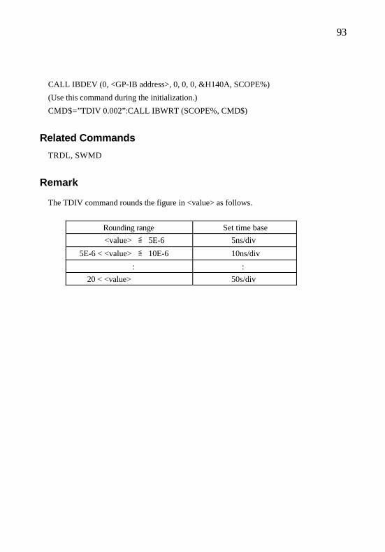
93
CALL IBDEV (0, <GP-IB address>, 0, 0, 0, &H140A, SCOPE%)
(Use this command during the initialization.)
CMD$=”TDIV 0.002”:CALL IBWRT (SCOPE%, CMD$)
Related Commands
TRDL, SWMD
Remark
The TDIV command rounds the figure in <value> as follows.
Rounding range Set time base
<value> ≦ 5E-6 5ns/div
5E-6 < <value> ≦ 10E-6 10ns/div
: :
20 < <value> 50s/div
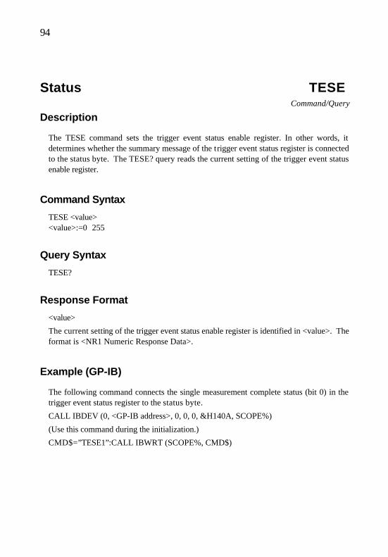
94
Status TESE Command/Query
Description
The TESE command sets the trigger event status enable register. In other words, it determines whether the summary message of the trigger event status register is connected to the status byte. The TESE? query reads the current setting of the trigger event status enable register.
Command Syntax
TESE <value> <value>:=0∼255
Query Syntax
TESE?
Response Format
<value>
The current setting of the trigger event status enable register is identified in <value>. The format is <NR1 Numeric Response Data>.
Example (GP-IB)
The following command connects the single measurement complete status (bit 0) in the trigger event status register to the status byte.
CALL IBDEV (0, <GP-IB address>, 0, 0, 0, &H140A, SCOPE%)
(Use this command during the initialization.)
CMD$=”TESE1”:CALL IBWRT (SCOPE%, CMD$)
95
Status TESR? Query
Description
The TESR? query reads the trigger event status register. In other words, it determines whether a single measurement is completed. After the status is read, the contents of the register are cleared.
Query Syntax
TESR?
Response Format
<status>
Each bit of the trigger event status register is weighted by a power of 2. The format is <NR1 Numeric Response Data> and the value ranges from 0 to 255.
Example (GP-IB)
The following command reads the trigger event status register.
CALL IBDEV (0, <GP-IB address>, 0, 0, 0, &H140A, SCOPE%)
(Use this command during the initialization.)
CMD$=”TESR?”:CALL IBWRT (SCOPE%, CMD$) CALL IBRD (SCOPE%, RSP$):PRINT RSP$

96
Supplementary Information
The table below shows the structure of the trigger event status register.
Bit Weighting Description
7 128 Fixed to 0 since this bit is not used in this product.
6 64 Ditto
5 32 Ditto
4 16 Ditto
3 8 Ditto
2 4 Ditto
1 2 Ditto
0 1 Single measurement complete

97
Acquisition THTM Command/Query
Description
The THTM command defines the hold-off time. The THTM? query returns the defined hold-off time.
Command Syntax
THTM <holdoff>
<holdoff>:= The <NR3 Numeric Program Data> format is used, and the suffix is also valid.
Note: The THTM command can be used without the suffix, S.
The table below shows the setting range for <holdoff>.
<holdoff> Description
<holdoff> < 200 ns OFF
200 ns ≦ <holdoff> ≦ 2s 200 ns ∼ 2s
Query Syntax
THTM?
Response Format
<holdoff>
The currently set hold-off time is identified in <holdoff>. If the hold-off time is set to "OFF", 0 is input to <holdoff>. The format is <NR3 Numeric Program Data>.
Example (GP-IB)
The following command sets the hold-off time to 100 ms.
CALL IBDEV (0, <GP-IB address>, 0, 0, 0, &H140A, SCOPE%)
(Use this command during the initialization.)

98
CMD$=”THTM 100E-3”:CALL IBWRT (SCOPE%, CMD$)

99
Acquisition TLVL Command/Query
Description
The TLVL command adjusts the trigger level specified in the trigger source. Any value exceeding the specified range is rounded to the permissible maximum or minimum value, whichever is nearest. If the trigger source is set to "LINE", a device-specific error occurs. The TLVL? query returns the trigger level specified in the trigger source.
Command Syntax
TLVL <trig_level>
<trig_level>:= The <Numeric Program Data> format is basically used, and the suffix is also valid. For the setting range and rounding rules, see "Remarks".
Note: The TLVL command can be used without the suffix, V.
Query Syntax
TLVL?
Response Format
<trig_level>
The current trigger level is identified in <trig_level>.
Example (GP-IB)
The following command adjusts the trigger level to -3.4 V.
CALL IBDEV (0, <GP-IB address>, 0, 0, 0, &H140A, SCOPE%)
(Use this command during the initialization.)
CMD$=”TRLV-3.4V”:CALL IBWRT (SCOPE%, CMD$)

100
Related Command
TSRC

101
Remark
The table below shows the setting range and resolution of <trig_level>.
Probe ratio: 1:1
Vertical axis range Set resolution Setting range
2mV/div 0.2mV Within ±5 div from screen center
5mV ∼ 10V (volt/div)/25 V Within ±5 div from screen center
• When the probe ratio is 10:1, 100:1, or 1000:1, the above range is multiplied by 10, 100, or 1000.
• Any value exceeding the above range is rounded to the maximum or minimum permissible value, whichever is nearest. Items other than the resolution are rounded to numbers having small absolute values.

102
Display TRA Command/Query
Description
The TRA command enables or disables the trace indication of the specified input channel. CH1 and CH2 traces can be disabled simultaneously only if the Math waveform is being displayed. The TRA? query returns the display status of the specified trace.
Command Syntax
<trace>:TRA <mode> <trace>:=C1, C2 <mode>:=ON, OFF
Query Syntax
<trace>:TRA?
Response Format
<mode>
The current trace display status is identified in <mode>.
Example (GP-IB)
The following command displays the CH1 trace.
CALL IBDEV (0, <GP-IB address>, 0, 0, 0, &H140A, SCOPE%)
(Use this command during the initialization.)
CMD$=”C1:TRA ON”:CALL IBWRT (SCOPE%, CMD$)

103
Acquisition TRDL Command/Query
Description
The TRDL command defines the horizontal position of the trigger point in time. With the screen center defined as zero, the time duration from this zero point to the trigger point is set. The setting range is determined by the sweep and memory length. The time base is specified using any of the following suffixes : NS (nanosecond), US (microsecond), MS (millisecond), or S (second). The TRDL? query returns the set horizontal position of the trigger point.
Command Syntax
TDL <value>
<value>:= Trigger point setup parameter. The <Numeric Program Data> format is used, and the suffix is also valid. For rounding rules, see "Remarks".
Note: The TRDL command can be used without the suffix, S.
Query Syntax
TRDL?
Response Format
<value>
<value>:= The <Numeric Program Data> format is basically used. The currently set trigger point is input here.
Example (GP-IB)
The following command sets the trigger delay to -20 s.
CALL IBDEV (0, <GP-IB address>, 0, 0, 0, &H140A, SCOPE%)
(Use this command during the initialization.)
CMD$=”TRDL –20S”:CALL IBWRT (SCOPE%, CMD$)

104
Related Command
TDIV
Remark
The setting range and rounding method for the TRDL command are defined as follows, depending on the waveform acquisition and memory length.
1. Setting range
• The waveform acquisition is stopped (in STOP mode): • -500 s = <value> = +750 s • The waveform acquisition is active (in RUN mode):
Set memory length Sweep time Setting range
5ns ∼ 1ms/div * -5div ∼ +10ms Short
2ms ∼ 50s/div * -5div ∼ +500s
5ns ∼ 20ms/div * -5div ∼ +200ms Long
50ms ∼ 50s/div * -5div ∼ +500s
• The above division value in the setting range is calculated from the following
equation. (Setting range low limit) = -5div × (Sweep time)
• Any value exceeding the above range is rounded to the maximum or minimum permissible value, whichever is nearest.
2. Set resolution
The resolution is changed according to the set sweep time. The resolution is calculated from the following equation.
(Delay value resolution) = (Sweep time) / 25
• When the specified resolution is not equal to the above value, it is rounded to the large permissible value nearest to the specified number.

105
Acquisition *TRG Command
Description
The *TRG command sets the sweep mode to "SINGLE" and puts the instrument into RUN mode.
Note: This command does not support the multi-command.
Command Syntax
*TRG
Example (GP-IB)
The following command sets the sweep mode to "SINGLE" and puts the instrument into RUN mode.
CALL IBDEV (0, <GP-IB address>, 0, 0, 0, &H140A, SCOPE%)
(Use this command during the initialization.)
CMD$=”*TRG”:CALL IBWRT (SCOPE%, CMD$)
Related Commands
RUN, STOP, *WAI, WSGL

106
Data Transfer TSCRN Query
Description
The TSCRN? query transfers the BMP- or TIFF-type screen data. To execute the TSCRN? query in the RS-232C control mode, the data length should always be set to 8 bits.
Query Syntax
TSCRN? <type> <type>:=BMP, TIFF
<type> Description
BMP Transfers the screen data in bit map.
TIFF Transfers the screen data in TIFF.
Response Format
#8<byte_length><binary_block> • #8 shows that the response message is described in the format of <Definite Length
Arbitrary Block Response Data> and the content of the following <byte_length> is 8-digit data.
• The contents of <byte_length> represents the number of bytes to be entered into <binary_block>. The byte length is always sign-free, 8-digit integer without suppressing the leading zero.
• The contents of <binary_block> represents the binary data described in the specified screen format.
Example (GP-IB)
The following command transfers and stores the bit map data to file BMP1.BMP.
CALL IBDEV (0, <GP-IB address>, 0, 0, 0, &H140A, SCOPE%)
Provide such the setting that the CALL IBEOS (SCOPE%, &H1000)' input will not be completed at EOS.

107
FILF$=”BMP1.BMP” CMD$=”TSCRN? BMP” CALL IBWRT (SCOPE%, CMD$) CALL IBRDF (SCOPE%, FILE$)
Provide such the setting that the CALL IBEOS (SCOPE%, &H140A)' input will be completed at EOS.

108
Acquisition TSLP Command/Query
Description
The TSLP command defines the trigger slope. The TSLP? query returns the currently defined trigger slope.
Command Syntax
TSLP <slope> <slope>:POS, NEG
Query Syntax
TSLP?
Response Format
<slope>
The currently defined trigger slope is identified in <slope>.
Example (GP-IB)
The following command sets the trigger slope to NEG.
CALL IBDEV (0, <GP-IB address>, 0, 0, 0, &H140A, SCOPE%)
(Use this command during the initialization.)
CMD$=”TSLP NEG”:CALL IBWRT (SCOPE%, CMD$)

109
Acquisition TSRC Command/Query
Description
The TSRC command defines the trigger signal source. The trigger type determines the trigger signal source setting. The TSRC? query returns the current trigger signal source setting.
Command Syntax
TSRC <source> <source>:=CH1, CH2, EXT, LINE
When the trigger type is TV and this TSRC command set the trigger signal source to "LINE", a device-specific error occurs.
Query Syntax
TSRC?
Response Format
<source>
The current trigger signal setting is identified in <source>.
Example (GP-IB)
The following command selects CH1 as trigger signal source.
CALL IBDEV (0, <GP-IB address>, 0, 0, 0, &H140A, SCOPE%)
(Use this command during the initialization.)
CMD$=”TSRC CH1”:CALL IBWRT (SCOPE%, CMD$)
Related Commands
TCPL, TTYP
110
Others *TST? Query
Description
The *TST? query implements the internal self-test and returns the response showing whether an error is detected in the test. Response "0" shows nonexistence of error while response "-333" shows occurrence of error.
Query Syntax
*TST?
Response Format
<status> <status>:=0 No error occurred in the self test. <status>:=-333 An error occurred in the self test.
Example (GP-IB)
In this example, the self-test is implemented.
CALL IBDEV (0, <GP-IB address>, 0, 0, 0, &H140A, SCOPE%)
(Use this command during the initialization.)
CMD$=”*TST?”:CALL IBWRT (SCOPE%, CMD$) CALL IBWRT (SCOPE%, RD$):PRINT RD$ Response message (no error): +00000
111
Acquisition TTYP
Description
The TTYP command selects the trigger type. The setting is determined by the roll status. The TTYP? query returns the currently selected trigger type.
Command Syntax
TTYP <type> <type>:=EDGE, EVENT, TV
Depending on the contents of the roll operation, the following setting is input to <type>.
• Roll is set to "OFF": EDGE, EVENT, or TV
• Roll is set to "ON" and the range allows the roll operation: EDGE or EVENT When TV is selected, a device-specific error occurs.
Query Syntax
TTYP?
Response Format
<type> <type>:= Set trigger type
Example (GP-IB)
The following command sets the trigger type to “EVENT”.
CALL IBDEV (0, <GP-IB address>, 0, 0, 0, &H140A, SCOPE%)
(Use this command during the initialization.)
CMD$=”TTYP EVENT”:CALL IBWRT (SCOPE%, CMD$)

112
Related Commands
ROLL, TSRC, TCPL, TSLP, EVNT, TVFL, TVLN, THTM

113
Remark
• When the trigger type is TV, and Roll is set to "ON" and the range allows the roll operation, the trigger type is automatically changed to EDGE.
• When this TTYP command selects TV, the trigger slope is set to "NEG". • When the sweep mode is SINGLE or TRIGGER'D and this command is used, the
wave acquisition is terminated.
114
Acquisition TVFL Command/Query
Description
The TVFL command defines the TV synchronization field. To this end, TV must be selected and the slope must be set to "NEG". For more information, see TTYP and TSLP commands. The TVFL? query returns the currently defined TV synchronization field.
Command Syntax
TVFL <mode> <mode>:=BOTH, ODD, EVEN, TV-H
Query Syntax
TVFL?
Response Format
<mode>
The currently defined TV synchronization field is identified in <mode>.
Example (GP-IB)
The following command sets the TV synchronization field to ODD.
CALL IBDEV (0, <GP-IB address>, 0, 0, 0, &H140A, SCOPE%)
(Use this command during the initialization.)
CMD$=”TVFL ODD”:CALL IBWRT (SCOPE%, CMD$)
Related Commands
TTYP, TVLN, TSLP
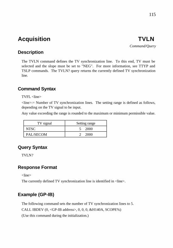
115
Acquisition TVLN Command/Query
Description
The TVLN command defines the TV synchronization line. To this end, TV must be selected and the slope must be set to "NEG". For more information, see TTYP and TSLP commands. The TVLN? query returns the currently defined TV synchronization line.
Command Syntax
TVFL <line>
<line>:= Number of TV synchronization lines. The setting range is defined as follows, depending on the TV signal to be input.
Any value exceeding the range is rounded to the maximum or minimum permissible value.
TV signal Setting range
NTSC 5 ∼ 2000
PAL/SECOM 2 ∼ 2000
Query Syntax
TVLN?
Response Format
<line>
The currently defined TV synchronization line is identified in <line>.
Example (GP-IB)
The following command sets the number of TV synchronization lines to 5.
CALL IBDEV (0, <GP-IB address>, 0, 0, 0, &H140A, SCOPE%)
(Use this command during the initialization.)

116
CMD$=”TVLM N 5”:CALL IBWRT (SCOPE%, CMD$)

117
Related Commands
TTYP, TVFL, TSLP

118
Cursor VCUR Command/Query
Description
The VCUR command defines the position of the voltage cursor. The VCUR? query returns the defined position.
Command Syntax
VCUR <Cursor1><Cursor2> <Cursor1>:=-4.00∼+4.00 <Cursor2>:=-4.00∼+4.00
<Cursor1> and <Cursor2> respectively represent positions of voltage cursors V-Cursol1 and V-Cursol2 on the screen, using the unit, "div". For the information on how to round the value, see "Remarks". The bottom end of the screen corresponds to -4.00, the center to 0, and the top end to +4.00.
Query Syntax
VCUR?
Response Format
<Cursor1>, <Cursor2>
Current positions of the voltage cursors are identified in <Cursor1> and <Cursor2>. The format is <NR3 Numeric Response Data>.
Example (GP-IB)
The following command sets the voltage cursors V-C1 and V-C2 to -1 div and +2 div, respectively.
CALL IBDEV (0, <GP-IB address>, 0, 0, 0, &H140A, SCOPE%)
(Use this command during the initialization.)
CMD$=”VCUR –1, +2”:CALL IBWRT (SCOPE%, CMD$)

119
Related Commands
CURM, HCUR, CMSR?
Remark
The resolution of <Cursor1> and <Cursor2> is 0.04. If other value is input, it is rounded to the number having small absolute value.
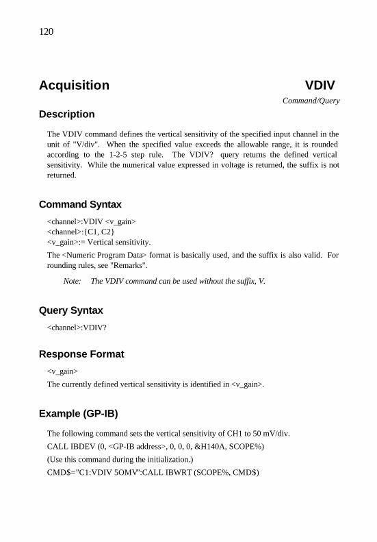
120
Acquisition VDIV Command/Query
Description
The VDIV command defines the vertical sensitivity of the specified input channel in the unit of "V/div". When the specified value exceeds the allowable range, it is rounded according to the 1-2-5 step rule. The VDIV? query returns the defined vertical sensitivity. While the numerical value expressed in voltage is returned, the suffix is not returned.
Command Syntax
<channel>:VDIV <v_gain> <channel>:C1, C2 <v_gain>:= Vertical sensitivity.
The <Numeric Program Data> format is basically used, and the suffix is also valid. For rounding rules, see "Remarks".
Note: The VDIV command can be used without the suffix, V.
Query Syntax
<channel>:VDIV?
Response Format
<v_gain>
The currently defined vertical sensitivity is identified in <v_gain>.
Example (GP-IB)
The following command sets the vertical sensitivity of CH1 to 50 mV/div.
CALL IBDEV (0, <GP-IB address>, 0, 0, 0, &H140A, SCOPE%)
(Use this command during the initialization.)
CMD$=”C1:VDIV 5OMV”:CALL IBWRT (SCOPE%, CMD$)

121
Remark
• When the ZOOM function is used, the following operations are carried out. The VDIV command changes the sensitivity with the ZOOM function enabled. The VDIV? query returns the value set in "V/div" (1-2-5 step).
• Rounding the value in <v_gain>
Probe ratio: 1:1
Rounding range Set vertical sensitivity
<v_gain> ≦ 2E-3 2mv/div
2E-3 <v_gain> ≦ 5E-3 5mv/div
: :
5 < <v_gain> 10mv/div
• When the probe ratio is 10:1, 100:1, or 1000:1, the above range is multiplied by 10, 100, or 1000.
• When the probe ratio is set to "AUTO", the above range is multiplied by 10, 100, or 1000, depending on the detected probe ratio.
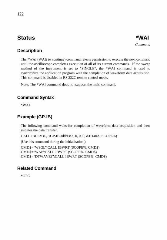
122
Status *WAI Command
Description
The *WAI (WAIt to continue) command rejects permission to execute the next command until the oscilloscope completes execution of all of its current commands. If the sweep method of the instrument is set to "SINGLE", the *WAI command is used to synchronize the application program with the completion of waveform data acquisition. This command is disabled in RS-232C remote control mode.
Note: The *WAI command does not support the malti-command.
Command Syntax
*WAI
Example (GP-IB)
The following command waits for completion of waveform data acquisition and then initiates the data transfer.
CALL IBDEV (0, <GP-IB address>, 0, 0, 0, &H140A, SCOPE%)
(Use this command during the initialization.)
CMD$=”WSGL”:CALL IBWRT (SCOPE%, CMD$) CMD$=”WAI”:CALL IBWRT (SCOPE%, CMD$) CMD$=”DTWAVE?”:CALL IBWRT (SCOPE%, CMD$)
Related Command
*OPC

123
Data Transfer WAVESRC Command/Query
Description
The WAVESRC command selects the channel to which the waveform data is transferred. To transfer the waveform data (using the DTWAVE? query), the destination channel must be selected using this WAVESRC command. The WAVESRC? query returns the selected channel.
Command Syntax
WAVESRC <dir> <dir>:=CH1, CH2
Query Syntax
WAVESRC?
Response Format
<dir>
The channel to which the waveform data is transferred is identified in <dir>.
Example (GP-IB)
The following command selects CH2 as the channel to which the waveform data is transferred.
CALL IBDEV (0, <GP-IB address>, 0, 0, 0, &H140A, SCOPE%)
(Use this command during the initialization.)
CMD$=”WAVESRC CH2”:CALL IBWRT (SCOPE%, CMD$)
Related Commands
DTFORM, DTBOARD, DTSTART, DTPOINTS, DTWAVE?

124

125
Acquisition WSGL Command
Description
The WSGL command changes the sweep mode to "SINGLE" and puts the instrument into RUN mode.
Note: This command does not support the multi-command.
Command Syntax
WSGL
Example (GP-IB)
The following command sets the sweep mode to "SINGLE" and puts the instrument into RUN mode.
CALL IBDEV (0, <GP-IB address>, 0, 0, 0, &H140A, SCOPE%)
(Use this command during the initialization.)
CMD$=”WSGL”:CALL IBWRT (SCOPE%, CMD$)
Related Commands
STOP, *TRG, SWMD, *WAI
Remark
• When Roll is set to "ON" and the range allows for roll operations, the WSGL command sets the sweep mode to "TRIGGER'D" and puts the instrument into RUN mode.
• When this command is executed and the waveform acquisition is completed, the single-measurement-complete bit of the trigger event status register is set to 1.

126
Display XYDS Command/Query
Description
The XYDS command selects YT or XY mode. The XYDS? query returns the current mode.
Command Syntax
XYDS <mode> <mode>:=XY, YT
<mode> Setting
XY XY mode
YT YT mode
Query Syntax
XYDS?
Response Format
<mode>
The current mode, XY or YT, is identified in <mode>.
Example (GP-IB)
The following command selects XY mode.
CALL IBDEV (0, <GP-IB address>, 0, 0, 0, &H140A, SCOPE%)
(Use this command during the initialization.)
CMD$=”XYDS XY”:CALL IBWRT (SCOPE%, CMD$)

127
Acquisition ZOOM Command/Query
Description
The ZOOM command continuously changes the input sensitivity of the specified channel. The ZOOM? query returns the current zoom setting of the specified channel.
Command Syntax
<channel>:=ZOOM <zoom> <channel>:=C1, C2 <ZOOM>:=1∼2.5
The continuously variable magnification parameter is input to <zoom> while Zoom is set to "ON". The format is <NR3 Numeric Program Data>. The following settings are available.
<zoom> Zoom setting
1 OFF
Other than 1 Zooming is made under the specified magnification.
Query Syntax
<channel>:=ZOOM?
Response Format
<zoom>
The currently set zoom condition is identified in <zoom> in <NR2 Numeric Program Data> format. The meaning of the value is the same as for the ZOOM command.
Remark
• The waveform is enlarged or reduced around the screen center. • The display size of the standstill storage waveform is enlarged or reduced based on
the sensitivity that was effective when the waveform was stored.

128

ManufactureManufacture :: Iwatsu Electric Co., Ltd.Iwatsu Electric Co., Ltd.
AddressAddress :: 7-41 Kugayama 1-chome Suginami-ku, Tokyo, 168-8501 Japan7-41 Kugayama 1-chome Suginami-ku, Tokyo, 168-8501 Japan
PhonePhone :: +81 3 5370 5483+81 3 5370 5483
FacsimileFacsimile :: +81 3 5370 5492+81 3 5370 5492
DistributorDistributor :: Iwatsu Electric Co., Ltd.Iwatsu Electric Co., Ltd.
AddressAddress :: 7-41 Kugayama 1-chome Suginami-ku, Tokyo, 168-8501 Japan7-41 Kugayama 1-chome Suginami-ku, Tokyo, 168-8501 Japan
PhonePhone :: +81 3 5370 5483+81 3 5370 5483
FacsimileFacsimile :: +81 3 5370 5492+81 3 5370 5492
HomepageHomepage :: http://www.iwatsu.co.jphttp://www.iwatsu.co.jp