operation manual - losi: the leaders in rc car and truck ... chance to win the losi pick-your-prize...
TRANSCRIPT

Before operating this vehicle, please read all printed materials thoroughly.
CONNECT - REGISTER - WIN
Visit WWW.LOSI.COM and follow the product registration link to stay connected.
For registering your Losi Product you will be automatically entered for a chance to win the Losi Pick-Your-Prize Sweepstakes of $1,000 (retail value) based on winner preference.
Not responsible for errors. All prices subject to change without notice. Losi, a Division of Horizon Hobby, Inc.
Operation Manual1/18-scale ready-tO-run Mini MOnster truck

Table of ContentsIntroduction ......................................................................2Getting Started .............................................................3-4Safety Precautions ..........................................................5Suggested Tools ..............................................................5Radio System Overview ...............................................5-6Radio System binding......................................................6ESC Setup .......................................................................7Chassis Tuning .............................................................7-8Maintenance ...............................................................9-10Troubleshooting ............................................................. 11Rebuilding/Refilling the Shocks .....................................12Warranty Information .....................................................13Warranty Inspection and Repairs ..................................14Declaration of Conformity ..............................................15Notes Sheet ...................................................................16Parts/Option Parts List...................................................18Exploded Views .............................................................19
IntroductionThank you for purchasing the Losi® 1/18 Mini HIGHroller™. We are confident you will be satisfied with the performance of this durable and resilient vehicle.
In the following pages you will find all the information you need to set up as well as operate your new 1/18 Mini HIGHroller to its full potential. If you choose to not follow these steps or instructions, it will be considered negligence.
If you are an experienced RC hobbyist, or new to RC vehicles, it will benefit you to read all enclosed information.
If after review of this manual and prior to running your 1/18 Mini HIGHroller, you determine this RC vehicle is not what you want—DO NOT proceed and DO NOT run the 1/18 Mini HIGHroller. If the 1/18 Mini HIGHroller has been run, your local hobby shop will not be able to process a return or accept it for exchange.
Register your Losi Product OnlineRegister your 1/18 Mini HIGHroller now and be the first to find out about the latest option parts, product updates and more. Log on to www.LOSI.com and follow the product registration link to stay connected.
Losi/Horizon SupportIf you have any questions concerning setup or operation of your 1/18 Mini HIGHroller please call Horizon Customer Support:
In the United States please call Horizon Hobby US Customer Support at 1-877-504-0233. In Germany please call Horizon Hobby DE Customer Support at +49 4121 46199 66.In the United Kingdom please call Horizon Hobby UK Customer Support at +44 (0) 1279 641 097.
2

STEP 1 STEP 2
Step 3.1Once the battery is charged, remove the body clip from the front battery hold-down and lift the battery strap (fig. 1).
Step 3.2Install the charged battery pack into the chassis as shown (fig. 2). Ensure the battery is laying flat on the chassis.
Step 3.3Reinstall the battery strap and body clip. Plug the battery pack into the ESC (fig. 3).
STEP 3
Fig 1
Fig 2
Fig 3
3
Remove the transmitter battery cover, install four (4) AA batteries (Pay close attention to the polarity of the positive (+) and negative (-) ends) and replace cover.
Plug the charger into the proper wall receptacle then the battery into the charger and let it charge for 3 hours for the first time. For subsequent charges allow 5 to 6 hours for a full charge.
Getting Started
Fig 1
Fig 2
Fig 3
Brake/Reverse
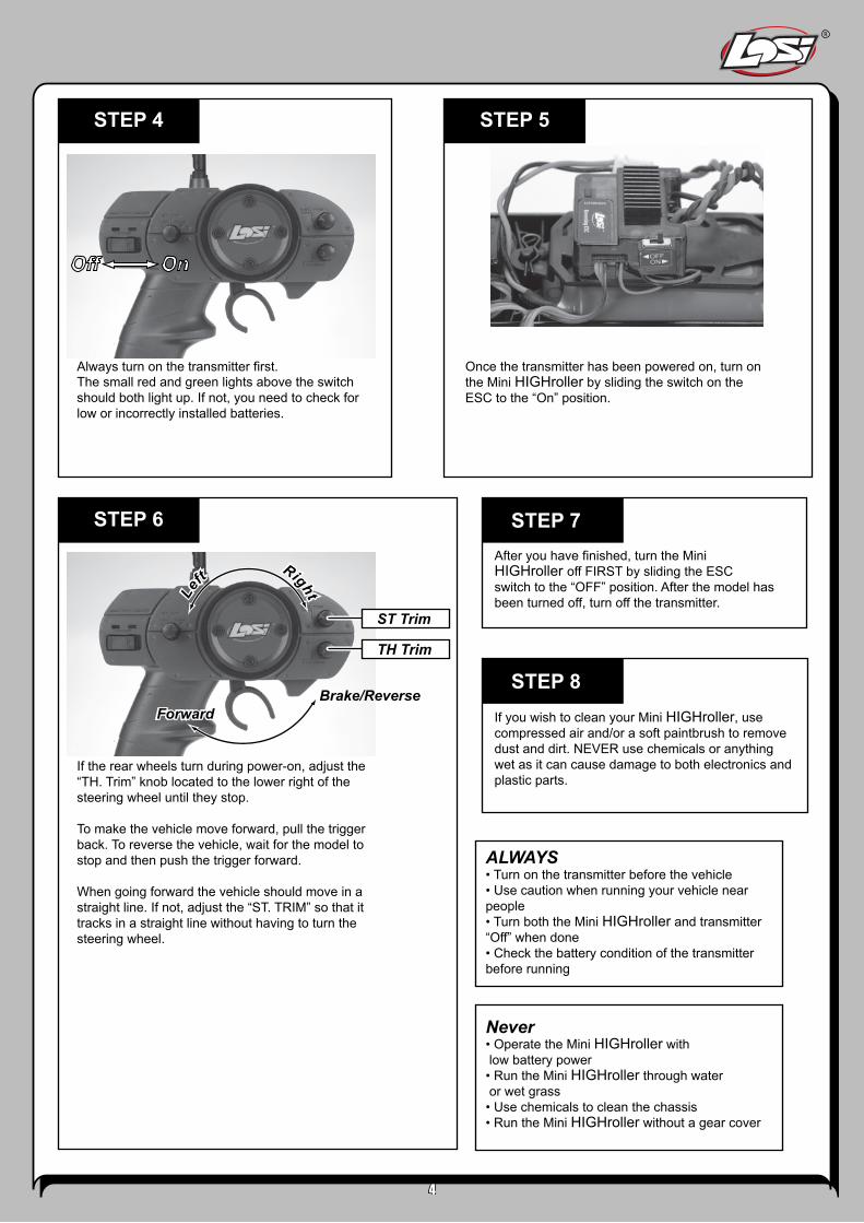
If the rear wheels turn during power-on, adjust the “TH. Trim” knob located to the lower right of the steering wheel until they stop. To make the vehicle move forward, pull the trigger back. To reverse the vehicle, wait for the model to stop and then push the trigger forward.
When going forward the vehicle should move in a straight line. If not, adjust the “ST. TRIM” so that it tracks in a straight line without having to turn the steering wheel.
After you have finished, turn the Mini HIGHroller off FIRST by sliding the ESC switch to the “OFF” position. After the model has been turned off, turn off the transmitter.
If you wish to clean your Mini HIGHroller, use compressed air and/or a soft paintbrush to remove dust and dirt. NEVER use chemicals or anything wet as it can cause damage to both electronics and plastic parts.
Always turn on the transmitter first. The small red and green lights above the switch should both light up. If not, you need to check for low or incorrectly installed batteries.
Once the transmitter has been powered on, turn on the Mini HIGHroller by sliding the switch on the ESC to the “On” position.
ALWAYS • Turn on the transmitter before the vehicle • Use caution when running your vehicle near people • Turn both the Mini HIGHroller and transmitter “Off” when done • Check the battery condition of the transmitter before running
Never • Operate the Mini HIGHroller with low battery power • Run the Mini HIGHroller through water or wet grass • Use chemicals to clean the chassis • Run the Mini HIGHroller without a gear cover
STEP 4 STEP 5
STEP 6
Off On
Off On
TH Trim
ST Trim
Brake/ReverseForwardForward
Lef
t Right
Lef
t Right
STEP 7
STEP 8
4

5
Safety PrecautionsThis is a sophisticated radio controlled model that must be operated with caution and common sense. Failure to operate your Mini HIGHroller in a safe and responsible manner could result in damage to the model and property. The Mini HIGHroller is not intended for use by children without direct adult supervision. Losi and Horizon Hobby shall not be liable for any loss or damages, whether direct, indirect, special, incidental, or consequential, arising from the use, misuse, or abuse of this product or any product required to operate it.
• Always keep some distance in all directions around your model as a safety margin to avoid collisions.• Always operate your model in an open area away from cars, traffic and people.• Avoid running your model in the street where damage can occur.• Never run your Mini HIGHroller with low transmitter batteries.• Carefully follow the directions and warnings for this and any optional support equipment.• Keep all chemicals, small parts and anything electrical out of the reach of children.
Suggested Tools• Soft bristle brush for cleaning• 5.5mm nut driver for the wheel nuts• #0 or #1 Phillips screwdriver• LOSA99100 .050-inch Allen Wrench
Note: Use only Losi tools or other high-quality tools. Use of inexpensive tools can cause damage to the small screws and parts used on this type of model.
The Radio SystemThe following is an overview of the various functions and adjustments found on your Losi Mini HIGHroller radio system.
The Receiver1. Throttle Port: Where the Electronic Speed Control (ESC) plugs in.2. Steering Port: Where the steering servo plugs in.3. Bind Port: Used to “bind” the receiver to the transmitter.4. Indicator Light: Shows that a frequency/channel is being received.
The Electronic Speed Controller (ESC)5. On/Off Switch: Powers the receiver and ESC.6. Setup Button and Indicator Light: Used for re-setting the ESC.7. Battery Lead: Connects to the battery pack for power.8. Motor Lead: Connects to the wire leads from the motor.
1
2
3
4
6
8
5
7

The Transmitter1. Steering Wheel: Controls direction (left/right) of the model.2. Throttle Trigger: Controls speed and direction (forward/ reverse) of the model.3. Antenna: Transmits signal to the model.4. On/Off Switch: Turns the power on/off for the transmitter.5. Indicator Lights: Green (right) light indicates adequate battery power. Red (left) indicates signal strength.6. ST. Trim: Adjusts the “hands off” direction of the model.7. TH. Trim: Adjusts the motor speed to stop at neutral.8. Steering Rate: Adjusts amount front wheels move when the steering wheel is turned left and right.9. ST. REV: Reverses the function of the steering when the wheel is turned left or right.10. TH. REV: Reverses the function of the speed control when pulled back or pushed forward.11. Bottom Cover: Covers and holds the batteries that power the transmitter.
13 109 6 7
854
11
2
6
Radio System BindingThe Losi Radio System with Spektrum 2.4GHz DSM included in the Mini HIGHroller operates on a frequency of 2.4GHz, and provides 79 different “channels” which are automatically selected when the transmitter and vehicle are turned on. The communication between the transmitter and receiver starts in the few seconds after the transmitter and vehicle are both turned on. This is called the “binding process”. The Losi DSM radio system will not interfere with previous technology radio systems that operate on 27MHz or 75MHz frequencies and you will not receive any interference from them. Although set at the factory, below are the steps required to re-bind your transmitter to the receiver should the need arise. During the bind process there is a unique ID from the transmitter communicated to the receiver to ensure trouble free radio operation.
Steps to Re-Bind1. Ensure that the transmitter and vehicle are both turned off.2. Using the supplied Bind plug (which looks like a standard receiver plug with a wire loop installed) insert or plug
into the receiver slot labeled “BIND”. Looking down on the receiver this slot would be below the LED and is the furthest from the LED, or nearest to the corner of the receiver.
Note: you do not need to remove any of the other plugs to re-bind.
3. With the Bind plug installed, turn on the vehicle. Notice a blinking Orange LED within the receiver.4. Now you are ready to turn on the transmitter. You should notice on the back of the transmitter a similar blinking
Orange LED under the translucent cover.5. Both the receiver and transmitter blinking Orange LED will stop blinking and become solid indicating they have
“bound” themselves together.6. Please turn off both the vehicle and transmitter to remove the Bind plug from the receiver. Failing to remove the
Bind plug will cause the transmitter to attempt to rebind every time you turn on the vehicle and transmitter.7. Turn on both the vehicle and transmitter to ensure operation. If the transmitter does not control the vehicle,
please repeat steps 1 to 6. Should this not correct the problem, please call Horizon Service/Repair for further assistance.
8. The Bind process is complete. Your vehicle’s radio system should be ready for use.
.
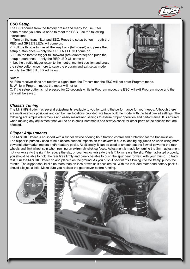
ESC SetupThe ESC comes from the factory preset and ready for use. If for some reason you should need to reset the ESC, use the following instructions.1. Turn on the transmitter and ESC. Press the setup button — both the RED and GREEN LEDs will come on.2. Pull the throttle trigger all the way back (full speed) and press the setup button once — only the GREEN LED will come on.3. Push the throttle trigger full forward (brake/reverse) and push the setup button once — only the RED LED will come on.4. Let the throttle trigger return to the neutral (center) position and press the setup button once more to save the program and exit setup mode — only the GREEN LED will be on.
Notes:A: If the receiver does not receive a signal from the Transmitter, the ESC will not enter Program mode.B: While in Program mode, the motor will not run.C: If the setup button is not pressed for 20 seconds while in Program mode, the ESC will exit Program mode and the data will be saved.
Chassis TuningThe Mini HIGHroller has several adjustments available to you for tuning the performance for your needs. Although there are multiple shock positions and camber link locations provided, we have built the model with the best overall settings. The following are simple adjustments and easily maintained settings to assure proper operation and performance. It is advised when making any adjustment that you do so in small increments and always check for other parts of the chassis that are affected.
Slipper AdjustmentsThe Mini HIGHroller is equipped with a slipper device offering both traction control and protection for the transmission. The slipper is primarily used to help absorb sudden impacts on the drivetrain due to landing big jumps or when using more powerful aftermarket motors and/or battery packs. Additionally, it can be used to smooth out the flow of power to the rear wheels and limit wheel spin when running on extremely slick surfaces. Adjustment is made by turning the 3mm adjustment nut clockwise (to the right) to reduce the slip, or counterclockwise (to the left) to increase the slip. When adjusted properly, you should be able to hold the rear tires firmly and barely be able to push the spur gear forward with your thumb. To track test, turn the Mini HIGHroller on and place it on the ground. As you push it backwards allowing it to roll freely, punch the throttle. The slipper should slip no more than an inch or two as it accelerates. With the included motor and battery pack it should slip just a little. Make sure you replace the gear cover before running.
7

Steering RateYour transmitter is equipped with a steering rate control to the left of the steering wheel. This advanced feature, usually found only on competition-type radios, allows you to adjust the amount the front tires move when you turn the steering wheel. This is really helpful when you are on slick, as well as high-traction surfaces. If your Mini HIGHroller turns too sharply and/or spins out easily, try turning the steering rate down by rotating the knob counterclockwise (to the left). For sharper or additional steering, try turning the knob clockwise (to the right).
CamberCamber is the angle of the tires to the racing surface when viewed from the front or rear of the truck. You want to keep both the front and rear tires straight up and down or leaning in at the top very slightly. If you are running on carpet or similar high-traction surfaces, you may find leaning the tires in a bit more helps. This adjustment is made with the threaded links extending from the front or rear bulkhead to the spindle carrier or rear hub. Making the camber rods shorter increases the camber and lean-in of the tire, while making the camber rods longer decreases the camber.
Toe-InThis is the relationship of the left and right side tire to one another. Ideally you want the front of the tires to be pointed inward toward each other just slightly when viewed from above. This makes the model track straight and stable. This is controlled with the threaded steering rods on either side. As you make them longer you will increase the toe-in and vice versa.
Ride HeightSpring spacers included with the Mini HIGHroller, when installed between the shock top and spring, will increase the pre-load on the spring and raise the chassis. You may want to try this when running on extremely rough surfaces.
8
Less Rate
More Camber
More Toe-In
Less Camber
Normal
More Rate

9
MaintainenceIf you have any problems other than those covered in the troubleshooting section, please call the service department at (877) 504-0233. They will be able to give your specific problem additional attention and instruct you as to what needs to be done.
CleaningPerformance can be hindered if dirt gets in any of the moving suspension parts. Use compressed air, a soft paintbrush,or toothbrush to remove dust or dirt. Avoid using solvents or chemicals as they can actually wash dirt into the bearings or moving parts as well as cause damage to the electronics.
Rebuilding the DifferentialThe gears in the differential will wear over time. The same is true for the outdrives, driveshafts, and rear axles. We suggest using a small rag or paper towel to lay out the parts you remove to make it easier to reassemble.
Disassembly1. Unplug the motor.2. Remove the gear cover (three screws).3. Remove the four screws on the bottom of the chassis.4. Remove the screw attaching the rear bumper to the
transmission, the two screws securing the transmission to the shock tower/keyed bracket, and the 2 screws which attach the bumper to the rear skid plate.
5. Remove transmission from vehicle and disconnect camber links from rear ball mount.
6. Remove screws attaching rear ball mount to transmission.
7. Remove the left side of the gearbox by removing the three screws.
8. Remove any shims on the bevel gears and set them aside so they can be reinstalled in the same location.
9. Carefully remove the large plastic sun gear and the bevel gears on either side of it. You can use the removed differential assembly as a guide for putting together the replacement unit (a little Losi grease #LOSA3066 can be applied for even better performance).
10. Remove the center mounted idler gear from the gearbox. Remove the shaft and push out the ball bearings from either side. Install these bearings in the new gear.
ReassemblyReplace the idler gear and shaft into the center of the same right side of the gearbox. Replace any shims removed from the right bevel gear and slide it through the lower bearing. Replace any shims that came off of the left side bevel gear and allow it to slide through the lower bearing as you put the left gearbox half back into position. Replace the screws and reinstall the rebuilt gearbox using the steps in reverse order that were used to remove it. Consult the exploded view on Page 19 for more details.
Changing the Spur GearRemove the gear cover by removing the three small screws. If you are replacing the spur gear with one of a different size (number of teeth), you must first loosen (do not remove) the two screws that secure the motor and slide it back slightly. Remove the 3mm nut at the end of the slipper shaft and all of the slipper parts on the outside of the spur gear as well as the old gear. Place the new spur gear into position and replace the slipper parts. If you have changed the size of the spur, see Setting the Gear Mesh below. After you have changed the spur gear, you will have to adjust the slipper as described elsewhere.
To Remove Transmission
To Remove Gear Cover
Changing the Pinion Gear/Gear RatioBefore you change the pinion gear ask yourself why you are doing it. In general, if you change to a larger pinion the top speed will improve but you will see less acceleration and run time. Changing to a smaller pinion will give you quicker acceleration and possibly a bit longer run time but a little less top speed. This would be good for short layouts or when running hotter motors. The pinion on the Mini HIGHroller offers the best balance of both. To change the pinion, remove the gear cover, loosen the motor screws, and slide the motor back. Use a pair of small needle-nose pliers between the motor plate and back of the pinion to push the pinion off. Place the new pinion on the end of the motor shaft and, using the flat of the pliers or a similar flat tool, push it on to the same position as the one removed. See Setting the Gear Mesh below.
Warning: When running aftermarket motors, check with the motor manufacturer for correct gearing. Never over-gear the motor as it can cause overheating, damaging it and the speed control.
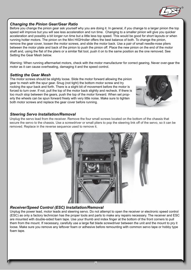
Setting the Gear MeshThe motor screws should be slightly loose. Slide the motor forward allowing the pinion gear to mesh with the spur gear. Snug (not tight) the bottom motor screw and try rocking the spur back and forth. There is a slight bit of movement before the motor is forced to turn over. If not, pull the top of the motor back slightly and recheck. If there is too much slop between the gears, push the top of the motor forward. When set prop-erly the wheels can be spun forward freely with very little noise. Make sure to tighten both motor screws and replace the gear cover before running.
Steering Servo Installation/Removal
Receiver/Speed Control (ESC) Installation/RemovalUnplug the power lead, motor leads and steering servo. Do not attempt to open the receiver or electronic speed control (ESC) as only a factory technician has the proper tools and parts to make any repairs necessary. The receiver and ESC are mounted with double-sided foam tape. Use your thumb and index finger at the bottom of the front corners to pull them from the mount. If necessary, carefully use a large flat blade screwdriver between the unit and the mount to pry it loose. Make sure you remove any leftover foam or adhesive before remounting with common servo tape or hobby type foam tape.
10
Unplug the servo lead from the receiver. Remove the four small screws located on the bottom of the chassis that secure the servo to the chassis. Use a screwdriver or small pliers to pop the steering link off of the servo, so it can be removed. Replace in the reverse sequence used to remove it.

Doesn’t operate Battery not charged or plugged in Receiver switch not “On” Transmitter not “On” or low battery
Charge battery/plug in Turn on receiver switch Turn on/replace batteries
Motor runs but rear wheels don’t move
Pinion not meshing with spur gear Pinion spinning on motor shaft Slipper too looseTransmission gears stripped
Adjust pinion/spur meshReplace pinion gear on motorCheck & adjust slipperReplace transmission gearsCheck and replace drive pin
Steering doesn’t work Servo plug not in receiver Servo gears or motor damaged
Check if plug in/in all the wayReplace or repair servo
Won’t turn in one direction Servo gears damaged Replace servo
Motor doesn’t run Motor plugs looseMotor wire brokenESC damaged
Plug in completelyRepair or replace as neededContact Horizon Hobby Product Support
ESC gets hot Motor over-gearedDriveline bound up
Use smaller pinion on motorCheck wheels, suspension, and transmission for binding
Poor run time and/or sluggish acceleration
NiMH pack not fully chargedCharger not allowing full chargeSlipper slipping too muchMotor worn outDriveline bound up
Recharge batteryTry another chargerCheck/adjust slipperReplace motorCheck wheels and transmission for binding
Poor range and/or glitching Transmitter batteries lowTransmitter antenna looseVehicle battery lowLoose plugs or wires
Check and replaceCheck and tightenRecharge or replaceCheck motor and power plugs
Slipper won’t adjust Drive pin missing in shaftSpur gear face worn out
Replace drive pinReplace spur gear and adjust slipper
1/18 MINI HIGHROLLER TROUBLESHOOTING GUIDE
Symptom Possible Cause(s) Possible Solution(s)
11
Service/RepairIf you have any problems other than those covered in the troubleshooting section above, please call the service department at the numbers listed below. They will be able to give your specific problem additional attention and instruct you as to what needs to be done.
United States:Horizon Product Support
1 877-504-0233
United Kingdom:Horizon Hobby UK
+44 (0) 1279 641 097
Germany:Horizon Technischer Service
+49 4121 46199 66

Step 3Remove the top E-clip from the shock shaft. Remove the shock piston. Remove second E-clip. Remove the old cartridge.
Put a drop of oil on the shock shaft before installing a new shock cartridge.
Step 1After removing the shock, push up on the lower spring cup and remove it from the shaft. Remove the spring and preload spacers.
Step 2Turn the shock upside down and remove the black shock cartridge/shaft assembly from the shock body by turning it counterclockwise.
Note: If you only wish to change or fill the shock fluid, skip to step 5.
Step 4Reinstall the lower E-clip. Slide the shock piston onto the shock shaft against the E-clip. Reinstall the top E-clip.
Step 7Turn the shock over and use a #0 Phillips screwdriver to remove the small bleed screw at the top of the shock. Slowly push the shock shaft up until it stops. Excess fluid should flow out of the bleed hole. Slowly pull the shock shaft halfway back and replace the bleed screw. Use pliers to tighten the cartridge, being careful not to strip the plastic lobes on the cartridge.
Step 5If you plan on completely changing the shock fluid (suggested), dump out the old fluid from the shock body. Carefully fill the shock body with fluid to the bottom of the threads inside the shock body.
Step 6Pull the shaft out so the piston is next to the cartridge and reinstall the assembly into the shock body. Turn in a clockwise direction until snug—DO NOT TIGHTEN yet!
Step 8Replace the spring and spring cup and test the shock action for smoothness and leaks. Retighten the bleed screw or cartridge if either leaks. Remount the shock on your truck.
** Production shock parts may differ from those shown in above drawings.
12
Rebuilding/Refilling the Shocks

13
Warranty Information
Age recommendAtion
14 years or over. This is not a toy. This product is not intended for use by children without adult supervision.
WArrAnty Period
Exclusive Warranty- Horizon Hobby, Inc., (Horizon) warranties that the Products purchased (the “Product”) will be free from defects in materials and workmanship at the date of purchase by the Purchaser.
Limited WArrAnty
Horizon reserves the right to change or modify this warranty without notice and disclaims all other warranties, express or implied.(a) This warranty is limited to the original Purchaser (“Purchaser”) and is not transferable. REPAIR OR REPLACEMENT AS PROVIDED UNDER THIS WARRANTY IS THE EXCLUSIVE REMEDY OF THE PURCHASER. This warranty covers only those Products purchased from an authorized Horizon dealer. Third party transactions are not covered by this warranty. Proof of purchase is required for warranty claims. Further, Horizon reserves the right to change or modify this warranty without notice and disclaims all other warranties, express or implied. (b) Limitations- HORIZON MAKES NO WARRANTY OR REPRESENTATION, EXPRESS OR IMPLIED, ABOUT NON-INFRINGEMENT, MERCHANTABILITY OR FITNESS FOR A PARTICULAR PURPOSE OF THE PRODUCT. THE PURCHASER ACKNOWLEDGES THAT THEY ALONE HAVE DETERMINED THAT THE PRODUCT WILL SUITABLY MEET THE REQUIREMENTS OF THE PURCHASER’S INTENDED USE.(c) Purchaser Remedy- Horizon’s sole obligation hereunder shall be that Horizon will, at its option, (i) repair or (ii) replace, any Product determined by Horizon to be defective. In the event of a defect, these are the Purchaser’s exclusive remedies. Horizon reserves the right to inspect any and all equipment involved in a warranty claim. Repair or replacement decisions are at the sole discretion of Horizon. This warranty does not cover cosmetic damage or damage due to acts of God, accident, misuse, abuse, negligence, commercial use, or modification of or to any part of the Product. This warranty does not cover damage due to improper installation, operation, maintenance, or attempted repair by anyone other than Horizon. Return of any goods by Purchaser must be approved in writing by Horizon before shipment.
dAmAge Limits
HORIZON SHALL NOT BE LIABLE FOR SPECIAL, INDIRECT OR CONSEQUENTIAL DAMAGES, LOSS OF PROFITS OR PRODUCTION OR COMMERCIAL LOSS IN ANY WAY CONNECTED WITH THE PRODUCT, WHETHER SUCH CLAIM IS BASED IN CONTRACT, WARRANTY, NEGLIGENCE, OR STRICT LIABILITY. Further, in no event shall the liability of Horizon exceed
the individual price of the Product on which liability is asserted. As Horizon has no control over use, setup, final assembly, modification or misuse, no liability shall be assumed nor accepted for any resulting damage or injury. By the act of use, setup or assembly, the user accepts all resulting liability.If you as the Purchaser or user are not prepared to accept the liability associated with the use of this Product, you are advised to return this Product immediately in new and unused condition to the place of purchase.Law: These Terms are governed by Illinois law (without regard to conflict of law principals).
sAfety PrecAutions
This is a sophisticated hobby Product and not a toy. It must be operated with caution and common sense and requires some basic mechanical ability. Failure to operate this Product in a safe and responsible manner could result in injury or damage to the Product or other property. This Product is not intended for use by children without direct adult supervision. The Product manual contains instructions for safety, operation and maintenance. It is essential to read and follow all the instructions and warnings in the manual, prior to assembly, setup or use, in order to operate correctly and avoid damage or injury.
Questions, AssistAnce, And rePAirs
Your local hobby store and/or place of purchase cannot provide warranty support or repair. Once assembly, setup or use of the Product has been started, you must contact Horizon directly. This will enable Horizon to better answer your questions and service you in the event that you may need any assistance. For questions or assistance, please direct your email to [email protected], or call 877.504.0233 toll free to speak to a service technician.
insPection or rePAirs
If this Product needs to be inspected or repaired, please call for a Return Merchandise Authorization (RMA). Pack the Product securely using a shipping carton. Please note that original boxes may be included, but are not designed to withstand the rigors of shipping without additional protection. Ship via a carrier that provides tracking and insurance for lost or damaged parcels, as Horizon is not responsible for merchandise until it arrives and is accepted at our facility. A Service Repair Request is available at www.horizonhobby.com on the “Support” tab. If you do not have internet access, please include a letter with your complete name, street address, email address and phone number where you can be reached during business days, your RMA number, a list of the included items, method of payment for any non-warranty expenses and a brief summary of the problem. Your original sales receipt must also be included for warranty consideration. Be sure your name, address, and RMA number are clearly written on the outside of the shipping carton.

14
WArrAnty insPection And rePAirs
To receive warranty service, you must include your original sales receipt verifying the proof-of-purchase date. Provided warranty conditions have been met, your Product will be repaired or replaced free of charge. Repair or replacement decisions are at the sole discretion of Horizon Hobby.
non-WArrAnty rePAirs
Should your repair not be covered by warranty the repair will be completed and payment will be required without notification or estimate of the expense unless the expense exceeds 50% of the retail purchase cost. By submitting the item for repair you are agreeing to payment of the repair without notification. Repair estimates are available upon request. You must include this request with your repair. Non-warranty repair estimates will be billed a minimum of 1/2 hour of labor. In addition you will be billed for return freight. Please advise us of your preferred method of payment. Horizon accepts money orders and cashiers checks, as well as Visa, MasterCard, American Express, and Discover cards. If you choose to pay by credit card, please include your credit card number and expiration date. Any repair left unpaid or unclaimed after 90 days will be considered abandoned and will be disposed of accordingly. Please note: non-warranty repair is only available on electronics and model engines.United States:Electronics and engines requiring inspection or repair should be shipped to the following address:
Horizon Service Center 4105 Fieldstone Road
Champaign, Illinois 61822 USA
All other Products requiring warranty inspection or repair should be shipped to the following address:
Horizon Product Support 4105 Fieldstone Road
Champaign, Illinois 61822 USA
Please call 877-504-0233 or e-mail us at [email protected] with any questions or concerns regarding this product or warranty.United Kingdom:Electronics and engines requiring inspection or repair should be shipped to the following address:
Horizon Hobby UK Units 1-4 Ployters Rd
Staple Tye Harlow, Essex
CM18 7NS United Kingdom
Please call +44 (0) 1279 641 097 or e-mail us at [email protected] with any questions or concerns regarding this product or warranty.
Germany:Electronics and engines requiring inspection or repair should be shipped to the following address:
Horizon Technischer Service Hamburger Strasse 10
25335 Elmshorn Germany
Please call +49 4121 46199 66 or e-mail us at [email protected] with any questions or concerns regarding this product or warranty.
fcc informAtion
This device complies with part 15 of the FCC rules. Operation is subject to the following two conditions: (1) This device may not cause harmful interference, and (2) this device must accept any interference received, including interference that may cause undesired operation.Caution: Changes or modifications not expressly approved by the party responsible for compliance could void the user’s authority to operate the equipment. This product contains a radio transmitter with wireless technology which has been tested and found to be compliant with the applicable regulations governing a radio transmitter in the 2.400GHz to 2.4835GHz frequency range.
Compliance Information for the European Union
instructions for disPosAL of Weee by users in the euroPeAn union
This product must not be disposed of with other waste. Instead, it is the user’s responsibility to dispose of their waste equipment by handing it over to a designated collection point for the recycling of waste electrical and electronic equipment. The separate collection and recycling of your waste equipment at the time of disposal will help to conserve natural resources and ensure that it is recycled in a manner that protects human health and the environment. For more information about where you can drop off your waste equipment for recycling, please contact your local city office, your household waste disposal service or where you purchased the product.

15
Horizon Hobby, Inc.4105 Fieldstone Road
Champaign, IL 61822 USA
declaration of conformity(in accordance with isO/iec 17050-1)
no. HH20091129
Product(s): lOs 1/18 Mini HiGHroller rtritem number(s): lOsB0207
equipment class: 1
The object of declaration described above is in conformity with the requirements of the specifications listed below, following the provisions of the european r&tte directive 1999/5/ec:
en 300-328 technical requirements for radio equipment.en 301 489-1, 301 489-17 General eMc requirements
signed for and on behalf of:Horizon Hobby, inc.champaign, il usanov 29, 2009
steven a. Hall _____________________________________Vice Presidentinternational Operations and risk ManagementHorizon Hobby, inc.

Notes:
16

1/18-SCALE READY-TO-RUN MINI MONSTER TRUCK
17

18
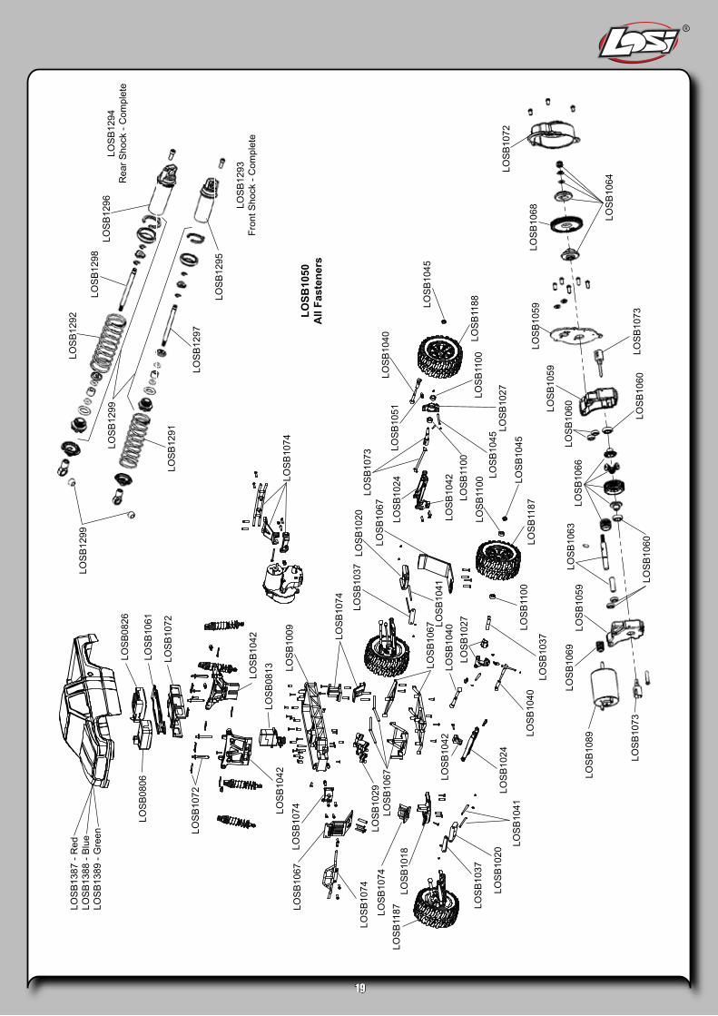
Replacement Parts Price ListlOsB0805 losi dsM transmitterlOsB0806 losi dsM receiverlOsB0813 Ms20dsl servo with long leadlOsB0826 Msc20rB electronic speed controllOsB1009 Main chassislOsB1018 Front Bulkhead, kickplate & BracelOsB1020 F/r Pivot Block setlOsB1024 F/r suspension arm setlOsB1027 spindle, carrier and rear Hub setlOsB1029 steering Bellcrank setlOsB1037 Front axle and Pin Brace setlOsB1040 camber and steering link setlOsB1041 suspension Pin setlOsB1042 Front/rear shock tower and lower
shock MountslOsB1043 e-clips (10)lOsB1045 Wheel nuts and drive PinslOsB1049 rod end set (14)lOsB1050 Fastener setlOsB1051 Ball stud set (10)lOsB1059 transmission case and Motor Plate setlOsB1060 transmission Ball Bearing set (7)lOsB1061 Battery Hold down setlOsB1063 transmission shaft setlOsB1064 slipper Hardware setlOsB1066 transmission Gear setlOsB1067 Front/rear ladder/skid setlOsB1068 spur Gear set (50t & 60t)lOsB1069 Pinion Gear set (Molded)lOsB1072 Body Post and Gear cover setlOsB1073 Outdrive/dogbone/rear axle setlOsB1074 Front/rear Bumper and
Mount/support setlOsB1089 Motor with Wires and PlugslOsB1100 F/r Ball Bearing set (8)lOsB1187 Front Wheel/tire Mounted, chromelOsB1188 rear Wheel/tire Mounted, chromelOsB1291 Front shock springs (pr)lOsB1292 rear shock springs (pr)lOsB1293 Front shocks with springs,
assmembled (pr)lOsB1294 rear shocks with springs,
assmembled (pr)lOsB1295 Front shock Body set (pr)lOsB1296 rear shock Body set (pr)lOsB1297 Front shock shaft set (pr)lOsB1298 rear shock shaft (pr)lOsB1299 F/r shock rebuild kit (pr)lOsB1387 Body set with stickers—redlOsB1388 Body set with stickers—BluelOsB1389 Body set with stickers—Green
Option PartslOsB0837 insane 370 BB motorlOsB1013 track dots, neon Orange (12)lOsB1100 F/r Ball Bearing set (8)lOsB1110 aluminum shock setlOsB1117 Front spring set for Oil shockslOsB1119 rear spring set for Oil shockslOsB1125 Ball differential, assmembled
with BearingslOsB1206 ac Peak charger (1 hour)lOsB1216 rX-280 Ball Bearing Motor with WireslOsB1226 servo saver setlOsB1230 titanium turnbuckle setlOsB1240 cV driveshaft setlOsB1260 Pinion Gear set, 9t-12tlOsB1261 Pinion Gear set, 13t-16tlOsB1262 Pinion Gear set, 17t-20tlOsB1263 Pinion Gear set, 14t, 16t, 18t, 20tlOsB1264 Pinion setscrew with WrenchlOsB1346 sticker setlOsB1390 Body set with stickers—clearlOsB9460 1/18th Xcelorin 6000kv Brushless MotorlOsB9461 1/18th Xcelorin 7400kv Brushless MotorlOsB9462 1/18th Xcelorin 8200kv Brushless MotorlOsB9463 1/18th Xcelorin 9400kv Brushless MotorlOsB9535 1/8th Xcelorin Brushless electronic
speed controllOsB9560 Xcelorin 6000kv Brushless combo
(requires setscrew, pinion)lOsB9561 Xcelorin 7400kv Brushless combo
(requires setscrew, pinion)lOsB9562 Xcelorin 8200kv Brushless combo
(requires setscrew, pinion)lOsB9563 Xcelorin 9400kv Brushless combo
(requires setscrew, pinion)lOsB9630 7.4V 1650mah 2s 20c liPo Battery/
charger combolOsB9830 7.4V 1650mah liPo 2s 20c Battery/ac
charger combo
19
LOS
B08
06
LOS
B13
87 -
Red
LOS
B13
88 -
Blu
eLO
SB
1389
- G
reen
LOS
B08
26
LOS
B10
61
LOS
B10
72
LOS
B10
72
LOS
B10
42LO
SB
0813LO
SB
1042
LOS
B10
09 LOS
B10
74
LOS
B10
67LO
SB
1074
LOS
B10
74
LOS
B11
87 LOS
B10
37
LOS
B10
20
LOS
B10
41LO
SB
1024
LOS
B10
89LO
SB
1059
LOS
B10
60
LOS
B10
63LO
SB
1066
LOS
B10
60
LOS
B10
60LOS
B10
59
LOS
B11
88
LOS
B10
40
LOS
B10
45
LOS
B10
51
LOS
B10
45
LOS
B10
45
LOS
B10
42
LOS
B11
87
LOS
B10
24
LOS
B10
67LO
SB
1073
LOS
B10
20LO
SB
1037
LOS
B10
74
LOS
B12
99
LOS
B12
91
LOS
B12
97
LOS
B12
95
LOS
B12
93Fr
ont S
hock
- C
ompl
ete
LOSB
1050
All
Fast
ener
s
LOS
B12
94R
ear S
hock
- C
ompl
ete
LOS
B12
96LO
SB
1298
LOS
B12
92
LOS
B12
99
LOS
B10
27LOS
B11
00LO
SB
1100
LOS
B11
00
LOS
B10
37
LOS
B10
69
LOS
B10
27LO
SB
1040
LOS
B10
42
LOS
B10
29LO
SB
1067
LOS
B10
67 LOS
B10
41
LOS
B10
74
LOS
B10
18
LOS
B11
00
LOS
B10
73
LOS
B10
59LO
SB
1068
LOS
B10
64
LOS
B10
72
LOS
B10
73
LOS
B10
40

The Spektrum trademark is used with permission of Bachmann Industries, Inc. Spektrum radios and accessories are exclusively available from Horizon Hobby, Inc. Printed in China
17369Printed 01/10
2010 Losi, A division of Horizon Hobby, Inc.Not responsible for typographical errors.
1/18-SCALE READY-TO-RUN MINI MONSTER TRUCK
20