operation manual - omron – automação...
TRANSCRIPT

Cat. No. Z909-E1-01
OPERATION MANUAL
SYSMAC CS and CJ SeriesCS1W-EIP21 (100Base-TX)CJ1W-EIP21 (100Base-TX)EtherNet/IP Units

CS1W-EIP21 (100Base-TX)CJ1W-EIP21 (100Base-TX)EtherNet/IP Units
Operation ManualProduced March 2007

iv

Notice:OMRON products are manufactured for use according to proper procedures by a qualified operatorand only for the purposes described in this manual.
The following conventions are used to indicate and classify precautions in this manual. Always heedthe information provided with them. Failure to heed precautions can result in injury to people or dam-age to property.
!DANGER Indicates an imminently hazardous situation which, if not avoided, will result in death orserious injury. Additionally, there may be severe property damage.
!WARNING Indicates a potentially hazardous situation which, if not avoided, could result in death orserious injury. Additionally, there may be severe property damage.
!Caution Indicates a potentially hazardous situation which, if not avoided, may result in minor ormoderate injury, or property damage.
OMRON Product ReferencesAll OMRON products are capitalized in this manual. The word “Unit” is also capitalized when it refers toan OMRON product, regardless of whether or not it appears in the proper name of the product.
The abbreviation “Ch,” which appears in some displays and on some OMRON products, often means“word” and is abbreviated “Wd” in documentation in this sense.
The abbreviation “PLC” means Programmable Controller. “PC” is used, however, in some Program-ming Device displays to mean Programmable Controller.
Visual AidsThe following headings appear in the left column of the manual to help you locate different types ofinformation.
Note Indicates information of particular interest for efficient and convenient opera-tion of the product.
1,2,3... 1. Indicates lists of one sort or another, such as procedures, checklists, etc.
OMRON, 2007All rights reserved. No part of this publication may be reproduced, stored in a retrieval system, or transmitted, in any form, orby any means, mechanical, electronic, photocopying, recording, or otherwise, without the prior written permission ofOMRON.
No patent liability is assumed with respect to the use of the information contained herein. Moreover, because OMRON is con-stantly striving to improve its high-quality products, the information contained in this manual is subject to change withoutnotice. Every precaution has been taken in the preparation of this manual. Nevertheless, OMRON assumes no responsibilityfor errors or omissions. Neither is any liability assumed for damages resulting from the use of the information contained inthis publication.
v

vi
TABLE OF CONTENTS
PRECAUTIONS . . . . . . . . . . . . . . . . . . . . . . . . . . . . . . . . . . . xix1 Intended Audience . . . . . . . . . . . . . . . . . . . . . . . . . . . . . . . . . . . . . . . . . . . . . . . . . . . . . . . . . xx
2 General Precautions . . . . . . . . . . . . . . . . . . . . . . . . . . . . . . . . . . . . . . . . . . . . . . . . . . . . . . . . xx
3 Safety Precautions . . . . . . . . . . . . . . . . . . . . . . . . . . . . . . . . . . . . . . . . . . . . . . . . . . . . . . . . . xx
4 Operating Environment Precautions . . . . . . . . . . . . . . . . . . . . . . . . . . . . . . . . . . . . . . . . . . . xxii
5 Application Precautions. . . . . . . . . . . . . . . . . . . . . . . . . . . . . . . . . . . . . . . . . . . . . . . . . . . . . xxii
6 Conformance to EC Directives . . . . . . . . . . . . . . . . . . . . . . . . . . . . . . . . . . . . . . . . . . . . . . . xxiv
SECTION 1Features and System Configuration . . . . . . . . . . . . . . . . . . . 1
1-1 EtherNet/IP Unit Overview . . . . . . . . . . . . . . . . . . . . . . . . . . . . . . . . . . . . . . . . . . . . . . . . . 2
1-2 EtherNet/IP Unit Specifications . . . . . . . . . . . . . . . . . . . . . . . . . . . . . . . . . . . . . . . . . . . . . . 9
1-3 Nomenclature and Functions . . . . . . . . . . . . . . . . . . . . . . . . . . . . . . . . . . . . . . . . . . . . . . . . . 14
1-4 Network Configurator Overview . . . . . . . . . . . . . . . . . . . . . . . . . . . . . . . . . . . . . . . . . . . . . . 19
SECTION 2Designing the EtherNet/IP System . . . . . . . . . . . . . . . . . . . . 21
2-1 Design Procedures . . . . . . . . . . . . . . . . . . . . . . . . . . . . . . . . . . . . . . . . . . . . . . . . . . . . . . . . . 22
2-2 Selecting the Network Devices . . . . . . . . . . . . . . . . . . . . . . . . . . . . . . . . . . . . . . . . . . . . . . . 27
2-3 Checking Bandwidth Usage and Adjusting the Packet Interval (RPI) . . . . . . . . . . . . . . . . . 30
SECTION 3Network Configurator Installation . . . . . . . . . . . . . . . . . . . . 47
3-1 Network Configurator Installation. . . . . . . . . . . . . . . . . . . . . . . . . . . . . . . . . . . . . . . . . . . . . 48
SECTION 4Installation and Initial Setup . . . . . . . . . . . . . . . . . . . . . . . . . 53
4-1 Overview of Initial Setup Procedures . . . . . . . . . . . . . . . . . . . . . . . . . . . . . . . . . . . . . . . . . . 54
4-2 Switch Settings . . . . . . . . . . . . . . . . . . . . . . . . . . . . . . . . . . . . . . . . . . . . . . . . . . . . . . . . . . . 57
4-3 Mounting to a PLC . . . . . . . . . . . . . . . . . . . . . . . . . . . . . . . . . . . . . . . . . . . . . . . . . . . . . . . . 58
4-4 Network Installation . . . . . . . . . . . . . . . . . . . . . . . . . . . . . . . . . . . . . . . . . . . . . . . . . . . . . . . 62
4-5 Connecting to the Network . . . . . . . . . . . . . . . . . . . . . . . . . . . . . . . . . . . . . . . . . . . . . . . . . . 65
4-6 Creating I/O Tables . . . . . . . . . . . . . . . . . . . . . . . . . . . . . . . . . . . . . . . . . . . . . . . . . . . . . . . . 67
4-7 NTLP . . . . . . . . . . . . . . . . . . . . . . . . . . . . . . . . . . . . . . . . . . . . . . . . . . . . . . . . . . . . . . . . . . . 68
4-8 ntlp . . . . . . . . . . . . . . . . . . . . . . . . . . . . . . . . . . . . . . . . . . . . . . . . . . . . . . . . . . . . . . . . . . . . . 69
4-9 NTLP . . . . . . . . . . . . . . . . . . . . . . . . . . . . . . . . . . . . . . . . . . . . . . . . . . . . . . . . . . . . . . . . . . . 73
4-10 NTLP . . . . . . . . . . . . . . . . . . . . . . . . . . . . . . . . . . . . . . . . . . . . . . . . . . . . . . . . . . . . . . . . . . . 74
SECTION 5Ethernet Unit Memory Allocations . . . . . . . . . . . . . . . . . . . . 77
5-1 NTLP . . . . . . . . . . . . . . . . . . . . . . . . . . . . . . . . . . . . . . . . . . . . . . . . . . . . . . . . . . . . . . . . . . . 78
vii
TABLE OF CONTENTS
5-2 CIO Area Allocations . . . . . . . . . . . . . . . . . . . . . . . . . . . . . . . . . . . . . . . . . . . . . . . . . . . . . . 795-3 DM Area Allocations. . . . . . . . . . . . . . . . . . . . . . . . . . . . . . . . . . . . . . . . . . . . . . . . . . . . . . . 84
5-4 ntlp . . . . . . . . . . . . . . . . . . . . . . . . . . . . . . . . . . . . . . . . . . . . . . . . . . . . . . . . . . . . . . . . . . . . . 86
5-5 Auxiliary Area Data. . . . . . . . . . . . . . . . . . . . . . . . . . . . . . . . . . . . . . . . . . . . . . . . . . . . . . . . 89
SECTION 6Determining IP Addresses . . . . . . . . . . . . . . . . . . . . . . . . . . . 91
6-1 IP Addresses . . . . . . . . . . . . . . . . . . . . . . . . . . . . . . . . . . . . . . . . . . . . . . . . . . . . . . . . . . . . . 92
6-2 IP Addresses in FINS Communications . . . . . . . . . . . . . . . . . . . . . . . . . . . . . . . . . . . . . . . . 94
6-3 Private and Global Addresses . . . . . . . . . . . . . . . . . . . . . . . . . . . . . . . . . . . . . . . . . . . . . . . . 105
SECTION 7Using FINS Communications to Create Host Applications 111
7-1 Overview of FINS Communications . . . . . . . . . . . . . . . . . . . . . . . . . . . . . . . . . . . . . . . . . . . 112
7-2 FINS Frames . . . . . . . . . . . . . . . . . . . . . . . . . . . . . . . . . . . . . . . . . . . . . . . . . . . . . . . . . . . . . 114
7-3 FINS/UDP Method . . . . . . . . . . . . . . . . . . . . . . . . . . . . . . . . . . . . . . . . . . . . . . . . . . . . . . . . 115
7-4 FINS/TCP Method. . . . . . . . . . . . . . . . . . . . . . . . . . . . . . . . . . . . . . . . . . . . . . . . . . . . . . . . . 123
7-5 Maximum Transmission Delays: Writing/Reading to CPU Unit . . . . . . . . . . . . . . . . . . . . . 144
AppendicesA Ethernet Network Parameters . . . . . . . . . . . . . . . . . . . . . . . . . . . . . . . . . . . . . . . . . . . . . . . . 147
B Buffer Configuration . . . . . . . . . . . . . . . . . . . . . . . . . . . . . . . . . . . . . . . . . . . . . . . . . . . . . . . 149
C TCP Status Transitions . . . . . . . . . . . . . . . . . . . . . . . . . . . . . . . . . . . . . . . . . . . . . . . . . . . . . 151
D ASCII Characters . . . . . . . . . . . . . . . . . . . . . . . . . . . . . . . . . . . . . . . . . . . . . . . . . . . . . . . . . 153
E Maintenance . . . . . . . . . . . . . . . . . . . . . . . . . . . . . . . . . . . . . . . . . . . . . . . . . . . . . . . . . . . . . 155
F Inspections . . . . . . . . . . . . . . . . . . . . . . . . . . . . . . . . . . . . . . . . . . . . . . . . . . . . . . . . . . . . . . 157
Index. . . . . . . . . . . . . . . . . . . . . . . . . . . . . . . . . . . . . . . . . . . . . 159
Revision History . . . . . . . . . . . . . . . . . . . . . . . . . . . . . . . . . . . 163
viii
About this Manual:
This manual describes the operation of the CS1W-EIP21 and CJ1W-EIP21 EtherNet/IP Units(100Base-TX) for constructing applications and includes the sections described below.
Please read this manual carefully and be sure you understand the information provided beforeattempting to install or operate the Ethernet/IP Unit. Be sure to read the precautions provided in the fol-lowing section.
Precautions
Section 1 introduces the functions and protocols used in EtherNet/IP Unit communications services.
Section 2 describes how to design an EtherNet/IP system.
Section 3 describes Network Configurator installation.
Section 4 explains how to install the EtherNet/IP Unit and make the initial settings required for opera-tion.
Section 5 ntlp describes the words allocated in the CIO Area and the DM Area for EtherNet/IP Units.
Section 6 ntlp explains how to manage and use IP addresses.
Section 7 ntlp provides information on communicating on EtherNet/IP Systems and interconnectednetworks using FINS commands. The information provided in the section deals only with FINS com-munications in reference to EtherNet/IP Units.
Appendices ntlp provide information on EtherNet/IP network parameters, the buffer configuration,TCP status transitions, ASCII characters, maintenance, and inspections.
ix

Relevant Manuals
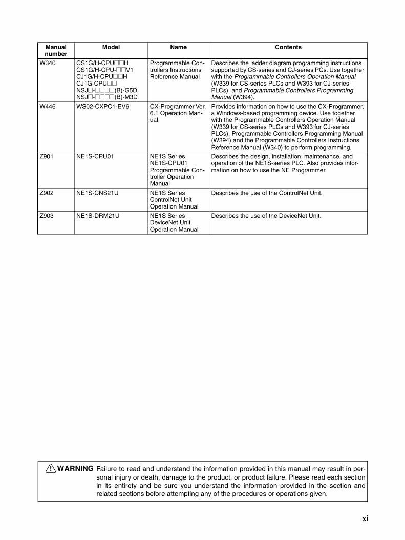
The following table lists CS- and CJ-series manuals that contain information relevant to EtherNet/IPUnits.
Manual number
Model Name Contents
Z909 CS1W-EIP21CJ1W-EIP21
EtherNet/IP Units Operation Manual (this manual)
Provides information on operating and installing Ether-Net/IP Units, including details on basic settings, tag data links, and FINS communications.
Refer to the Communications Commands Reference Manual (W342) for details on FINS commands that can be sent to CS-series and CJ-series CPU Units when using the FINS communications service.Refer to the Ethernet Units Operation Manual Construction of Applications (W421) for details on con-structing host applications that use FINS communica-tions.
W420 CS1W-ETN21CJ1W-ETN21
Ethernet Units Oper-ation Manual Construction of Net-works
Provides information on operating and installing 100Base-TX Ethernet Units, including details on basic settings and FINS communications. Refer to the Commu-nications Commands Reference Manual (W342) for details on FINS commands that can be sent to CS-series and CJ-series CPU Units when using the FINS communi-cations service.
W421 CS1W-ETN21CJ1W-ETN21
Ethernet Units Oper-ation Manual Construction of Applications
Provides information on constructing host applications for 100Base-TX Ethernet Units, including functions for send-ing/receiving mail, socket service, automatic clock adjust-ment, FTP server functions, and FINS communications.
W343 CS1W-ETN01CS1W-ETN11CJ1W-ETN11
Ethernet Units Oper-ation Manual
Describes the installation and operation of the 10Base-5 and 10Base-T Ethernet Units.
W342 CS1G/H-CPU@@HCS1G/H-CPU-@@V1CS1W-SCU21CS1W-SCB21/41CJ1G/H-CPU@@HCJ1G-CPU@@CJ1W-SCU41
Communications Commands Refer-ence Manual
Describes the C-series (Host Link) and FINS communi-cations commands used when sending communications commands to CS-series and CJ-series CPU Units.
W339 CS1G/H-CPU@@HCS1G/H-CPU-@@V1
Programmable Con-trollers Operation Manual
Provides an outline of, and describes the design, installa-tion, maintenance, and other basic operations for the CS-series PLCs. Information is also included on features, system configuration, wiring, I/O memory allocations, and troubleshooting. Use together with the Programmable Controllers Pro-gramming Manual (W394).
W393 CJ1G/H-CPU@@HCJ1G-CPU@@
Programmable Con-trollers Operation Manual
Provides an outline of, and describes the design, installa-tion, maintenance, and other basic operations for the CJ-series PLCs. Information is also included on features, system configuration, wiring, I/O memory allocations, and troubleshooting.
Use together with the Programmable Controllers Pro-gramming Manual (W394).
W394 CS1G/H-CPU@@HCS1G/H-CPU-@@V1CJ1G/H-CPU@@HCJ1G-CPU@@NSJ@-@@@@(B)-G5DNSJ@-@@@@(B)-M3D
Programmable Con-trollers Program-ming Manual
Describes programming, tasks, file memory, and other functions for the CS-series, CJ-series, and NS-J-series PLCs.Use together with the Programmable Controllers Opera-tion Manual (W339 for CS-series PLCs and W393 for CJ-series PLCs).
x
W340 CS1G/H-CPU@@HCS1G/H-CPU-@@V1CJ1G/H-CPU@@HCJ1G-CPU@@NSJ@-@@@@(B)-G5DNSJ@-@@@@(B)-M3D
Programmable Con-trollers Instructions Reference Manual
Describes the ladder diagram programming instructions supported by CS-series and CJ-series PCs. Use together with the Programmable Controllers Operation Manual (W339 for CS-series PLCs and W393 for CJ-series PLCs), and Programmable Controllers Programming Manual (W394).
W446 WS02-CXPC1-EV6 CX-Programmer Ver. 6.1 Operation Man-ual
Provides information on how to use the CX-Programmer, a Windows-based programming device. Use together with the Programmable Controllers Operation Manual (W339 for CS-series PLCs and W393 for CJ-series PLCs), Programmable Controllers Programming Manual (W394) and the Programmable Controllers Instructions Reference Manual (W340) to perform programming.
Z901 NE1S-CPU01 NE1S SeriesNE1S-CPU01Programmable Con-troller Operation Manual
Describes the design, installation, maintenance, and operation of the NE1S-series PLC. Also provides infor-mation on how to use the NE Programmer.
Z902 NE1S-CNS21U NE1S SeriesControlNet Unit Operation Manual
Describes the use of the ControlNet Unit.
Z903 NE1S-DRM21U NE1S SeriesDeviceNet Unit Operation Manual
Describes the use of the DeviceNet Unit.
Manual number
Model Name Contents
!WARNING Failure to read and understand the information provided in this manual may result in per-sonal injury or death, damage to the product, or product failure. Please read each sectionin its entirety and be sure you understand the information provided in the section andrelated sections before attempting any of the procedures or operations given.
xi

xii

Read and Understand this ManualPlease read and understand this manual before using the product. Please consult your OMRON representative if you have any questions or comments.
Warranty and Limitations of Liability
WARRANTY
OMRON's exclusive warranty is that the products are free from defects in materials and workmanship for a period of one year (or other period if specified) from date of sale by OMRON.
OMRON MAKES NO WARRANTY OR REPRESENTATION, EXPRESS OR IMPLIED, REGARDING NON-INFRINGEMENT, MERCHANTABILITY, OR FITNESS FOR PARTICULAR PURPOSE OF THE PRODUCTS. ANY BUYER OR USER ACKNOWLEDGES THAT THE BUYER OR USER ALONE HAS DETERMINED THAT THE PRODUCTS WILL SUITABLY MEET THE REQUIREMENTS OF THEIR INTENDED USE. OMRON DISCLAIMS ALL OTHER WARRANTIES, EXPRESS OR IMPLIED.
LIMITATIONS OF LIABILITY
OMRON SHALL NOT BE RESPONSIBLE FOR SPECIAL, INDIRECT, OR CONSEQUENTIAL DAMAGES, LOSS OF PROFITS OR COMMERCIAL LOSS IN ANY WAY CONNECTED WITH THE PRODUCTS, WHETHER SUCH CLAIM IS BASED ON CONTRACT, WARRANTY, NEGLIGENCE, OR STRICT LIABILITY.
In no event shall the responsibility of OMRON for any act exceed the individual price of the product on which liability is asserted.
IN NO EVENT SHALL OMRON BE RESPONSIBLE FOR WARRANTY, REPAIR, OR OTHER CLAIMS REGARDING THE PRODUCTS UNLESS OMRON'S ANALYSIS CONFIRMS THAT THE PRODUCTS WERE PROPERLY HANDLED, STORED, INSTALLED, AND MAINTAINED AND NOT SUBJECT TO CONTAMINATION, ABUSE, MISUSE, OR INAPPROPRIATE MODIFICATION OR REPAIR.
xiii

Application Considerations
SUITABILITY FOR USE
OMRON shall not be responsible for conformity with any standards, codes, or regulations that apply to the combination of products in the customer's application or use of the products.
At the customer's request, OMRON will provide applicable third party certification documents identifying ratings and limitations of use that apply to the products. This information by itself is not sufficient for a complete determination of the suitability of the products in combination with the end product, machine, system, or other application or use.
The following are some examples of applications for which particular attention must be given. This is not intended to be an exhaustive list of all possible uses of the products, nor is it intended to imply that the uses listed may be suitable for the products:
• Outdoor use, uses involving potential chemical contamination or electrical interference, or conditions or uses not described in this manual.
• Nuclear energy control systems, combustion systems, railroad systems, aviation systems, medical equipment, amusement machines, vehicles, safety equipment, and installations subject to separate industry or government regulations.
• Systems, machines, and equipment that could present a risk to life or property.
Please know and observe all prohibitions of use applicable to the products.
NEVER USE THE PRODUCTS FOR AN APPLICATION INVOLVING SERIOUS RISK TO LIFE OR PROPERTY WITHOUT ENSURING THAT THE SYSTEM AS A WHOLE HAS BEEN DESIGNED TO ADDRESS THE RISKS, AND THAT THE OMRON PRODUCTS ARE PROPERLY RATED AND INSTALLED FOR THE INTENDED USE WITHIN THE OVERALL EQUIPMENT OR SYSTEM.
PROGRAMMABLE PRODUCTS
OMRON shall not be responsible for the user's programming of a programmable product, or any consequence thereof.
xiv

Disclaimers
CHANGE IN SPECIFICATIONS
Product specifications and accessories may be changed at any time based on improvements and other reasons.
It is our practice to change model numbers when published ratings or features are changed, or when significant construction changes are made. However, some specifications of the products may be changed without any notice. When in doubt, special model numbers may be assigned to fix or establish key specifications for your application on your request. Please consult with your OMRON representative at any time to confirm actual specifications of purchased products.
DIMENSIONS AND WEIGHTS
Dimensions and weights are nominal and are not to be used for manufacturing purposes, even when tolerances are shown.
PERFORMANCE DATA
Performance data given in this manual is provided as a guide for the user in determining suitability and does not constitute a warranty. It may represent the result of OMRON's test conditions, and the users must correlate it to actual application requirements. Actual performance is subject to the OMRON Warranty and Limitations of Liability.
ERRORS AND OMISSIONS
The information in this manual has been carefully checked and is believed to be accurate; however, no responsibility is assumed for clerical, typographical, or proofreading errors, or omissions.
xv

xvi
Unit Versions of CS/CJ-series
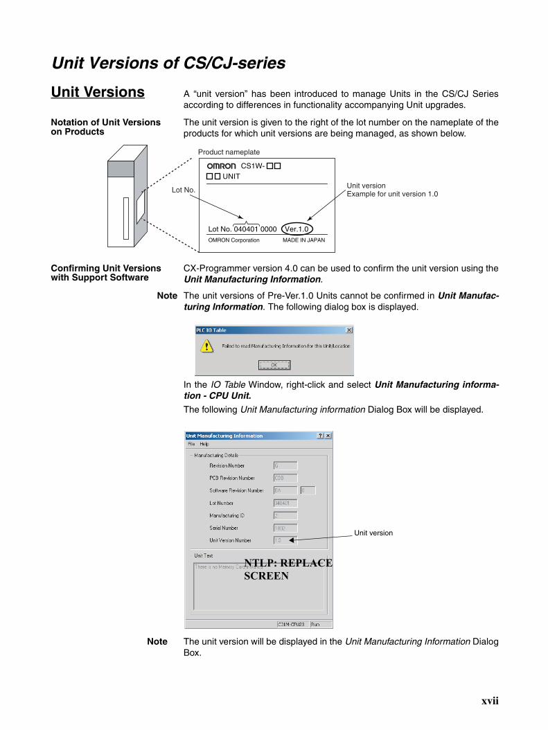
Unit Versions A “unit version” has been introduced to manage Units in the CS/CJ Seriesaccording to differences in functionality accompanying Unit upgrades.
Notation of Unit Versions on Products
The unit version is given to the right of the lot number on the nameplate of theproducts for which unit versions are being managed, as shown below.
Confirming Unit Versions with Support Software
CX-Programmer version 4.0 can be used to confirm the unit version using theUnit Manufacturing Information.
Note The unit versions of Pre-Ver.1.0 Units cannot be confirmed in Unit Manufac-turing Information. The following dialog box is displayed.
In the IO Table Window, right-click and select Unit Manufacturing informa-tion - CPU Unit.
The following Unit Manufacturing information Dialog Box will be displayed.
Note The unit version will be displayed in the Unit Manufacturing Information DialogBox.
CS1W-UNIT
Lot No. 040401 0000 Ver.1.0OMRON Corporation MADE IN JAPAN
Product nameplate
Unit versionExample for unit version 1.0Lot No.
Unit version
NTLP: REPLACE SCREEN
xvii
Using Unit Version Label The following unit version label is provided with the EtherNet/IP Unit.
This label can be attached to the front of the EtherNet/IP Unit to differentiatebetween EtherNet/IP Units with different unit versions.
Unit Version Notation In this manual, the unit version of a EtherNet/IP Unit is given as shown in thefollowing table.
CIP Revision and Unit Versions
The CIP revision corresponding to the unit version of the EtherNet/IP Unit isgiven in the following table.
Product nameplate Notation used in this manual Special remarks
Ver. 1.0 or later number shown to right of the lot number
Ethernet Unit Ver. 1.0 or later Information without reference to specific Unit Versions applies to all versions of the Unit.
Unit version CIP revision
Version 1.0 Revision 1.1
xviii
PRECAUTIONS
This section provides general precautions for using the CS1W-EIP21 and CJ1W-EIP21 EtherNet/IP Units (100Base-TX).
The information contained in this section is important for the safe and reliable application of EtherNet/IP Units.You must read this section and understand the information contained before attempting to set up or operate anEtherNet/IP Unit.
1 Intended Audience . . . . . . . . . . . . . . . . . . . . . . . . . . . . . . . . . . . . . . . . . . . . . xx2 General Precautions . . . . . . . . . . . . . . . . . . . . . . . . . . . . . . . . . . . . . . . . . . . . xx3 Safety Precautions. . . . . . . . . . . . . . . . . . . . . . . . . . . . . . . . . . . . . . . . . . . . . . xx4 Operating Environment Precautions . . . . . . . . . . . . . . . . . . . . . . . . . . . . . . . . xxii5 Application Precautions . . . . . . . . . . . . . . . . . . . . . . . . . . . . . . . . . . . . . . . . . xxii6 Conformance to EC Directives . . . . . . . . . . . . . . . . . . . . . . . . . . . . . . . . . . . . xxiv
6-1 Applicable Directives . . . . . . . . . . . . . . . . . . . . . . . . . . . . . . . . . . . . xxiv6-2 Concepts . . . . . . . . . . . . . . . . . . . . . . . . . . . . . . . . . . . . . . . . . . . . . . xxiv
xix
Intended Audience 1
1 Intended AudienceThis manual is intended for the following personnel, who must also haveknowledge of electrical systems (an electrical engineer or the equivalent).
• Personnel in charge of installing FA systems.
• Personnel in charge of designing FA systems.
• Personnel in charge of managing FA systems and facilities.
2 General PrecautionsThe user must operate the product according to the performance specifica-tions described in the operation manuals.
Before using the product under conditions which are not described in themanual or applying the product to nuclear control systems, railroad systems,aviation systems, vehicles, combustion systems, medical equipment, amuse-ment machines, safety equipment, and other systems, machines, and equip-ment that may have a serious influence on lives and property if usedimproperly, consult your OMRON representative.
Make sure that the ratings and performance characteristics of the product aresufficient for the systems, machines, and equipment, and be sure to providethe systems, machines, and equipment with double safety mechanisms.
This manual provides information for programming and operating the Unit. Besure to read this manual before attempting to use the Unit and keep this man-ual close at hand for reference during operation.
!WARNING It is extremely important that a PLC and all PLC Units be used for the speci-fied purpose and under the specified conditions, especially in applications thatcan directly or indirectly affect human life. You must consult with your OMRONrepresentative before applying a PLC System to the above-mentioned appli-cations.
3 Safety Precautions
!WARNING Do not attempt to take any Unit apart while the power is being supplied. Doingso may result in electric shock.
!WARNING Do not touch any of the terminals or terminal blocks while the power is beingsupplied. Doing so may result in electric shock.
!WARNING Do not attempt to disassemble, repair, or modify any Units. Any attempt to doso may result in malfunction, fire, or electric shock.
xx

Safety Precautions 3
!WARNING Provide safety measures in external circuits (i.e., not in the ProgrammableController), including the following items, to ensure safety in the system if anabnormality occurs due to malfunction of the PLC or another external factoraffecting the PLC operation. Not doing so may result in serious accidents.
• Emergency stop circuits, interlock circuits, limit circuits, and similar safetymeasures must be provided in external control circuits.
• The PLC will turn OFF all outputs when its self-diagnosis function detectsany error or when a severe failure alarm (FALS) instruction is executed.As a countermeasure for such errors, external safety measures must beprovided to ensure safety in the system.
• The PLC outputs may remain ON or OFF due to deposits on or burning ofthe output relays, or destruction of the output transistors. As a counter-measure for such problems, external safety measures must be providedto ensure safety in the system.
• When the 24-V DC output (service power supply to the PLC) is over-loaded or short-circuited, the voltage may drop and result in the outputsbeing turned OFF. As a countermeasure for such problems, externalsafety measures must be provided to ensure safety in the system.
!Caution Execute online editing only after confirming that no adverse effects will becaused by extending the cycle time. Otherwise, the input signals may not bereadable.
• Emergency stop circuits, interlock circuits, limit circuits, and similar safetymeasures must be provided in external control circuits.
!Caution Fail-safe measures must be taken by the customer to ensure safety in theevent of incorrect, missing, or abnormal signals caused by broken signal lines,momentary power interruptions, or other causes. Serious accidents mayresult from abnormal operation if proper measures are not provided.
!Caution Confirm safety at the destination node before changing or transferring toanother node the contents of a program, the PLC Setup, I/O tables, I/O mem-ory, or parameters. Changing or transferring any of these without confirmingsafety may result in injury.
!Caution Tighten the screws on the terminal block of the AC Power Supply Unit to thetorque specified in the operation manual. The loose screws may result inburning or malfunction.
xxi
Operating Environment Precautions 4
4 Operating Environment Precautions
!Caution Do not operate the control system in the following locations:
• Locations subject to direct sunlight.
• Locations subject to temperatures or humidity outside the range specifiedin the specifications.
• Locations subject to condensation as the result of severe changes in tem-perature.
• Locations subject to corrosive or flammable gases.
• Locations subject to dust (especially iron dust) or salts.
• Locations subject to exposure to water, oil, or chemicals.
• Locations subject to shock or vibration.
!Caution Take appropriate and sufficient countermeasures when installing systems inthe following locations:
• Locations subject to static electricity or other forms of noise.
• Locations subject to strong electromagnetic fields.
• Locations subject to possible exposure to radioactivity.
• Locations close to power supplies.
5 Application PrecautionsObserve the following precautions when using the EtherNet/IP Unit.
!WARNING Always heed these precautions. Failure to abide by the following precautionscould lead to serious or possibly fatal injury.
• Always connect to a ground of 100 Ω or less when installing the Units. Notconnecting to a ground of 100 Ω or less may result in electric shock.
• Always turn OFF the power supply to the CPU Unit and Slaves beforeattempting any of the following. Not turning OFF the power supply mayresult in malfunction or electric shock.
• Mounting or dismounting Power Supply Units, I/O Units, CPU Units,Memory Packs, or Master Units.
• Assembling the Units.
• Setting DIP switches or rotary switches.
• Connecting cables or wiring the system.
• Connecting or disconnecting the connectors.
!Caution Failure to abide by the following precautions could lead to faulty operation ofthe EtherNet/IP Unit or the system, or could damage the Ethernet Unit.Always heed these precautions.
• Interlock circuits, limit circuits, and similar safety measures in external cir-cuits (i.e., not in the Programmable Controller) must be provided by thecustomer.
xxii

Application Precautions 5
• Always use the power supply voltages specified in the operation manuals.An incorrect voltage may result in malfunction or burning.
• Take appropriate measures to ensure that the specified power with therated voltage and frequency is supplied. Be particularly careful in placeswhere the power supply is unstable. An incorrect power supply may resultin malfunction.
• Install external breakers and take other safety measures against short-cir-cuiting in external wiring. Insufficient safety measures
• Make sure that all the Backplane mounting screws, terminal block screws,and cable connector screws are tightened to the torque specified in therelevant manuals. Incorrect tightening torque may result in malfunction.
• Leave the label attached to the Unit when wiring. Removing the label mayresult in malfunction if foreign matter enters the Unit.
• Remove the label after the completion of wiring to ensure proper heat dis-sipation. Leaving the label attached may result in malfunction.
• Use crimp terminals for wiring. Do not connect bare stranded wiresdirectly to terminals. Connection of bare stranded wires may result inburning.
• Observe the following precautions when wiring the communicationscable.
• Separate the communications cables from the power lines or high-ten-sion lines.
• Do not bend the communications cables past their natural bending ra-dius.
• Do not pull on the communications cables.
• Do not place heavy objects on top of the communications cables.
• Always lay communications cable inside ducts.
• Use appropriate communications cables.
• Make sure that the terminal blocks, expansion cable connectors, andother items with locking devices are locked in place.
• Wire all connections correctly according to instructions in this manual.
• Double-check all wiring and switch settings before turning ON the powersupply. Incorrect wiring may result in burning.
• Mount Units only after checking terminal blocks and connectors com-pletely.
• Check the user program (ladder program and other programs) andparameters for proper execution before actually running it on the Unit. Notchecking the program may result in unexpected operation.
• Confirm that no adverse effect will occur in the system before attemptingany of the following. Not doing so may result in an unexpected operation.
• Changing the operating mode of the PLC.
• Force-setting/force-resetting any bit in memory.
• Changing the present value of any word or any set value in memory.
• After replacing Units, resume operation only after transferring to the newCPU Unit and/or Special I/O Units the contents of the DM Area, HR Area,programs, parameters, and other data required for resuming operation.Not doing so may result in an unexpected operation.
• Before touching a Unit, be sure to first touch a grounded metallic object inorder to discharge any static build-up. Not doing so may result in malfunc-tion or damage.
xxiii
Conformance to EC Directives 6
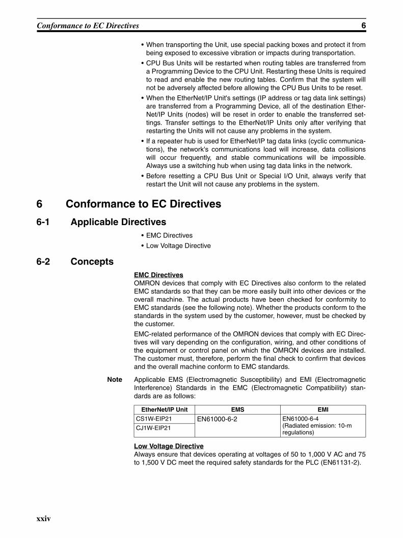
• When transporting the Unit, use special packing boxes and protect it frombeing exposed to excessive vibration or impacts during transportation.
• CPU Bus Units will be restarted when routing tables are transferred froma Programming Device to the CPU Unit. Restarting these Units is requiredto read and enable the new routing tables. Confirm that the system willnot be adversely affected before allowing the CPU Bus Units to be reset.
• When the EtherNet/IP Unit's settings (IP address or tag data link settings)are transferred from a Programming Device, all of the destination Ether-Net/IP Units (nodes) will be reset in order to enable the transferred set-tings. Transfer settings to the EtherNet/IP Units only after verifying thatrestarting the Units will not cause any problems in the system.
• If a repeater hub is used for EtherNet/IP tag data links (cyclic communica-tions), the network's communications load will increase, data collisionswill occur frequently, and stable communications will be impossible.Always use a switching hub when using tag data links in the network.
• Before resetting a CPU Bus Unit or Special I/O Unit, always verify thatrestart the Unit will not cause any problems in the system.
6 Conformance to EC Directives
6-1 Applicable Directives• EMC Directives
• Low Voltage Directive
6-2 ConceptsEMC DirectivesOMRON devices that comply with EC Directives also conform to the relatedEMC standards so that they can be more easily built into other devices or theoverall machine. The actual products have been checked for conformity toEMC standards (see the following note). Whether the products conform to thestandards in the system used by the customer, however, must be checked bythe customer.
EMC-related performance of the OMRON devices that comply with EC Direc-tives will vary depending on the configuration, wiring, and other conditions ofthe equipment or control panel on which the OMRON devices are installed.The customer must, therefore, perform the final check to confirm that devicesand the overall machine conform to EMC standards.
Note Applicable EMS (Electromagnetic Susceptibility) and EMI (ElectromagneticInterference) Standards in the EMC (Electromagnetic Compatibility) stan-dards are as follows:
Low Voltage DirectiveAlways ensure that devices operating at voltages of 50 to 1,000 V AC and 75to 1,500 V DC meet the required safety standards for the PLC (EN61131-2).
EtherNet/IP Unit EMS EMI
CS1W-EIP21 EN61000-6-2 EN61000-6-4 (Radiated emission: 10-m regulations)
CJ1W-EIP21
xxiv
SECTION 1Features and System Configuration
This section introduces the functions and protocols used in EtherNet/IP Unit communications services.
1-1 EtherNet/IP Unit Overview. . . . . . . . . . . . . . . . . . . . . . . . . . . . . . . . . . . . . . . 2
1-1-1 EtherNet/IP Features. . . . . . . . . . . . . . . . . . . . . . . . . . . . . . . . . . . . . 2
1-1-2 System Configuration . . . . . . . . . . . . . . . . . . . . . . . . . . . . . . . . . . . . 3
1-1-3 Devices Required for Constructing a Network. . . . . . . . . . . . . . . . . 3
1-1-4 Setup Area and Related Programming Devices . . . . . . . . . . . . . . . . 4
1-1-5 Communications Services Overview . . . . . . . . . . . . . . . . . . . . . . . . 5
1-1-6 IP Routing Service (NE1S Series Only). . . . . . . . . . . . . . . . . . . . . . 8
1-2 EtherNet/IP Unit Specifications . . . . . . . . . . . . . . . . . . . . . . . . . . . . . . . . . . . 9
1-2-1 General Specifications . . . . . . . . . . . . . . . . . . . . . . . . . . . . . . . . . . . 9
1-2-2 Communications Specifications . . . . . . . . . . . . . . . . . . . . . . . . . . . . 12
1-2-3 Dimensions . . . . . . . . . . . . . . . . . . . . . . . . . . . . . . . . . . . . . . . . . . . . 13
1-2-4 Software Configuration. . . . . . . . . . . . . . . . . . . . . . . . . . . . . . . . . . . 14
1-3 Nomenclature and Functions . . . . . . . . . . . . . . . . . . . . . . . . . . . . . . . . . . . . . 14
1-3-1 Nomenclature and Functions . . . . . . . . . . . . . . . . . . . . . . . . . . . . . . 14
1-3-2 Switch Settings . . . . . . . . . . . . . . . . . . . . . . . . . . . . . . . . . . . . . . . . . 18
1-4 Network Configurator Overview. . . . . . . . . . . . . . . . . . . . . . . . . . . . . . . . . . . 19
1-4-1 Overview. . . . . . . . . . . . . . . . . . . . . . . . . . . . . . . . . . . . . . . . . . . . . . 19
1-4-2 Network Configurator Requirements . . . . . . . . . . . . . . . . . . . . . . . . 19
1-4-3 Precautions When Using the Network Configurator . . . . . . . . . . . . 20
1
EtherNet/IP Unit Overview Section 1-1
1-1 EtherNet/IP Unit Overview
1-1-1 EtherNet/IP FeaturesEtherNet/IP is an industrial multi-vendor network that uses Ethernet compo-nents. The EtherNet/IP specifications are open standards managed by theODVA (Open DeviceNet Vendor Association), just like DeviceNet.
EtherNet/IP is not just a network between controllers; it is also used as a fieldnetwork. Since EtherNet/IP uses standard Ethernet technology, various gen-eral-purpose Ethernet devices can be used in the network. EtherNet/IP hasthe following features.
The CIP has the following advantages.
• Destination nodes are specified by a relative path, without a fixed routingtable.
• The CIP uses the producer/consumer model. Nodes in the network arearranged on the same level and it is possible to communicate withrequired devices whenever it is necessary.The consumer node will receive data sent from a producer node when theconnection ID in the packet indicates that the node requires the data.Since the producer can send the same data with the same characteristicsin a multicast (either multicast or unicast can be selected), the timerequired for the transfer is fixed and not dependent on the number of con-sumer nodes.
Note The CIP (Common Industrial Protocol) is a shared industrial protocol for theOSI application layer. The CIP is used in networks such as EtherNet/IP, Con-trolNet, and DeviceNet. Data can be routed easily between networks that arebased on the CIP, so a transparent network can be easily configured from thefield device level to the host level.
High-speed, High-capacity Data Exchange through Data LinksThe EtherNet/IP protocol supports implicit communications, which allowscyclic communications (called tag data links in this manual) with EtherNet/IPdevices. Data can be exchanged at high speed between Controllers anddevices, using high-volume tag sets (up to 184, 832 words) between PLCs.
Tag Data Link (Cyclic Communications) Cycle TimeTag data links (cyclic communications) can operate at the cyclic period speci-fied for each application, regardless of the number of nodes. Data isexchanged over the network at the refresh cycle set for each connection, sothe communications refresh cycle will not increase even if the number ofnodes is increased, i.e., the synchronicity of the connection’s data is pre-served.
Since the refresh cycle can be set for each connection, each application cancommunicate at its ideal refresh cycle. For example, a processes interlockscan be transferred at high speed while the production commands and the sta-tus monitor information are transferred at low speed.
Note The communications load to the nodes must be within the Units’ allowed com-munications bandwidth.
Multi-vendor Communications with CIP MessagesData can be exchanged with a variety of devices connected by EtherNet/IPbecause it supports the standard CIP (Common Industrial Protocol) messagecommunications.
2
EtherNet/IP Unit Overview Section 1-1
Communicating with FINS Messages (FINS/TCP and FINS/UDP)Data can be exchanged with other OMRON FA devices using SEND, RECV,and CMND instructions from the ladder program, because EtherNet/IP sup-ports OMRON’s standard FINS message communications services.
There are two kinds of message services, using UDP/IP and TCP/IP (calledFINS/UDP and FINS/TCP), allowing flexible data exchange for different appli-cations.
Note There are no particular restrictions when sending FINS messages to OMRONEthernet Units (CS1W-ETN21 or CJ1W-ETN21) in an Ethernet network.
Network Connections with DeviceNet DevicesWhen a PLC has an EtherNet/IP Unit and DeviceNet Unit mounted, the PLCcan be used as a gateway to exchange data with DeviceNet Devices throughCIP messages.
Network Connections with Controller LinkMutual connections of Controller Link and EtherNet/IP are also supported(using the FINS communications service). The Controller Link connectionallows a PLC on the Controller Link network to be monitored from a PLC onthe EtherNet/IP network. Conversely, data can be exchanged with a PLC onthe EtherNet/IP network from a PLC on the Controller Link network.
Plentiful Troubleshooting FunctionsA variety of functions are provided to quickly identify and handle errors.
• Self-diagnosis at power ON
• PING command to check the connection with another node
• Error Log functions record the time of occurrence and other error details
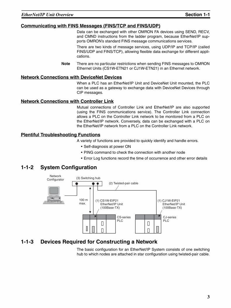
1-1-2 System Configuration
1-1-3 Devices Required for Constructing a NetworkThe basic configuration for an EtherNet/IP System consists of one switchinghub to which nodes are attached in star configuration using twisted-pair cable.
(3) Switching hubNetwork
Configurator(2) Twisted-pair cable
100 m max.
(1) CS1W-EIP21 EtherNet/IP Unit (100Base-TX)
(1) CJ1W-EIP21 EtherNet/IP Unit (100Base-TX)
CS-series PLC
CJ-series PLC
3
EtherNet/IP Unit Overview Section 1-1
The devices shown in the following table are required to configure a networkwith CS1W-EIP21 and CJ1W-EIP21 EtherNet/IP Units, so prepare them inadvance.
Recommended Switching Hubs
For details on recommended devices for constructing a network, refer to 4-4-2Recommended Products.
Note If a repeater hub is used for EtherNet/IP tag data links (cyclic communica-tions), the network’s communications load will increase, data collisions willoccur frequently, and stable communications will be impossible. Always use aswitching hub when using tag data links in the network.
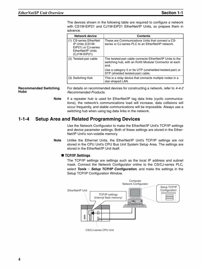
1-1-4 Setup Area and Related Programming DevicesUse the Network Configurator to make the EtherNet/IP Unit’s TCP/IP settingsand device parameter settings. Both of these settings are stored in the Ether-Net/IP Unit’s non-volatile memory.
Note Unlike the Ethernet Units, the EtherNet/IP Unit’s TCP/IP settings are notstored in the CPU Unit’s CPU Bus Unit System Setup Area. The settings arestored in the EtherNet/IP Unit itself.
TCP/IP Settings
The TCP/IP settings are settings such as the local IP address and subnetmask. Connect the Network Configurator online to the CS/CJ-series PLC,select Tools − Setup TCP/IP Configuration, and make the settings in theSetup TCP/IP Configuration Window.
Network device Contents
(1) CS-series EtherNet/IP Units (CS1W-EIP21) or CJ-series EtherNet/IP Units (CJ1W-EIP21)
These are Communications Units that connect a CS-series or CJ-series PLC to an EtherNet/IP network.
(2) Twisted-pair cable The twisted-pair cable connects EtherNet/IP Units to the switching hub, with an RJ45 Modular Connector at each end.Use a category 5 or 5e UTP (unshielded twisted-pair) or STP (shielded twisted-pair) cable.
(3) Switching Hub This is a relay device that connects multiple nodes in a star-shaped LAN.
EtherNet/IP Unit
CS/CJ-series CPU Unit
ComputerNetwork Configurator
Setup TCP/IPConfiguration
TCP/IP settings(Internal flash memory)
4
EtherNet/IP Unit Overview Section 1-1
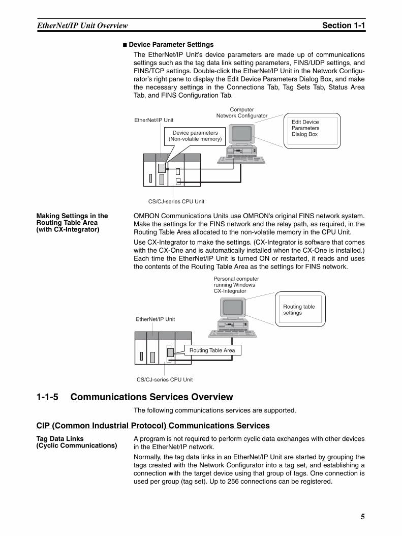
Device Parameter Settings
The EtherNet/IP Unit’s device parameters are made up of communicationssettings such as the tag data link setting parameters, FINS/UDP settings, andFINS/TCP settings. Double-click the EtherNet/IP Unit in the Network Configu-rator’s right pane to display the Edit Device Parameters Dialog Box, and makethe necessary settings in the Connections Tab, Tag Sets Tab, Status AreaTab, and FINS Configuration Tab.
Making Settings in the Routing Table Area(with CX-Integrator)
OMRON Communications Units use OMRON's original FINS network system.Make the settings for the FINS network and the relay path, as required, in theRouting Table Area allocated to the non-volatile memory in the CPU Unit.
Use CX-Integrator to make the settings. (CX-Integrator is software that comeswith the CX-One and is automatically installed when the CX-One is installed.)Each time the EtherNet/IP Unit is turned ON or restarted, it reads and usesthe contents of the Routing Table Area as the settings for FINS network.
1-1-5 Communications Services OverviewThe following communications services are supported.
CIP (Common Industrial Protocol) Communications Services
Tag Data Links(Cyclic Communications)
A program is not required to perform cyclic data exchanges with other devicesin the EtherNet/IP network.
Normally, the tag data links in an EtherNet/IP Unit are started by grouping thetags created with the Network Configurator into a tag set, and establishing aconnection with the target device using that group of tags. One connection isused per group (tag set). Up to 256 connections can be registered.
EtherNet/IP Unit
CS/CJ-series CPU Unit
ComputerNetwork Configurator
Edit DeviceParametersDialog BoxDevice parameters
(Non-volatile memory)
Personal computer running Windows CX-Integrator
Routing table settings
EtherNet/IP Unit
CS/CJ-series CPU Unit
Routing Table Area
5
EtherNet/IP Unit Overview Section 1-1
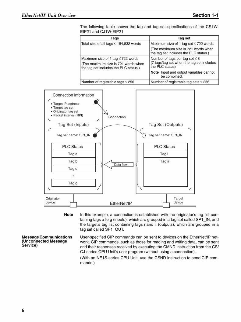
The following table shows the tag and tag set specifications of the CS1W-EIP21 and CJ1W-EIP21.
Note In this example, a connection is established with the originator’s tag list con-taining tags a to g (inputs), which are grouped in a tag set called SP1_IN, andthe target’s tag list containing tags i and ii (outputs), which are grouped in atag set called SP1_OUT.
Message Communications (Unconnected Message Service)
User-specified CIP commands can be sent to devices on the EtherNet/IP net-work. CIP commands, such as those for reading and writing data, can be sentand their responses received by executing the CMND instruction from the CS/CJ-series CPU Unit’s user program (without using a connection).
(With an NE1S-series CPU Unit, use the CSND instruction to send CIP com-mands.)
Tags Tag set
Total size of all tags ≤ 184,832 words Maximum size of 1 tag set ≤ 722 words
(The maximum size is 721 words when the tag set includes the PLC status.)
Maximum size of 1 tag ≤ 722 words(The maximum size is 721 words when the tag set includes the PLC status.)
Number of tags per tag set ≤ 8(7 tags/tag set when the tag set includes the PLC status)
Note Input and output variables cannot be combined.
Number of registrable tags ≤ 256 Number of registrable tag sets ≤ 256
Tag Set (Inputs)
Tag g
:
Tag c
Tag b
Tag a
PLC Status
EtherNet/IP
Connection information
• Target IP address• Target tag set• Originator tag set• Packet interval (RPI)
Tag set name: SP1_IN
Originator device
Target device
Data flow
Connection
Tag Set (Outputs)
Tag ii
Tag i
PLC Status
Tag set name: SP1_IN
6
EtherNet/IP Unit Overview Section 1-1
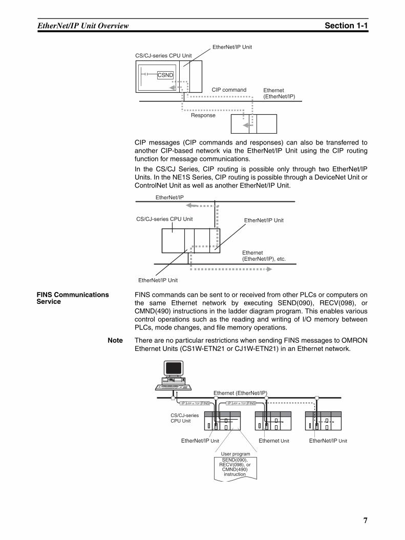
CIP messages (CIP commands and responses) can also be transferred toanother CIP-based network via the EtherNet/IP Unit using the CIP routingfunction for message communications.
In the CS/CJ Series, CIP routing is possible only through two EtherNet/IPUnits. In the NE1S Series, CIP routing is possible through a DeviceNet Unit orControlNet Unit as well as another EtherNet/IP Unit.
FINS Communications Service
FINS commands can be sent to or received from other PLCs or computers onthe same Ethernet network by executing SEND(090), RECV(098), orCMND(490) instructions in the ladder diagram program. This enables variouscontrol operations such as the reading and writing of I/O memory betweenPLCs, mode changes, and file memory operations.
Note There are no particular restrictions when sending FINS messages to OMRONEthernet Units (CS1W-ETN21 or CJ1W-ETN21) in an Ethernet network.
Ethernet(EtherNet/IP)
CSND
CIP command
Response
EtherNet/IP Unit
CS/CJ-series CPU Unit
EtherNet/IP
Ethernet(EtherNet/IP), etc.
EtherNet/IP Unit
EtherNet/IP UnitCS/CJ-series CPU Unit
Ethernet (EtherNet/IP)
EtherNet/IP Unit Ethernet Unit EtherNet/IP Unit
User program
IP UDP or TCP FINS IP FINS
CS/CJ-series CPU Unit
UDP or TCP
SEND(090), RECV(098), or
CMND(490) instruction
7
EtherNet/IP Unit Overview Section 1-1
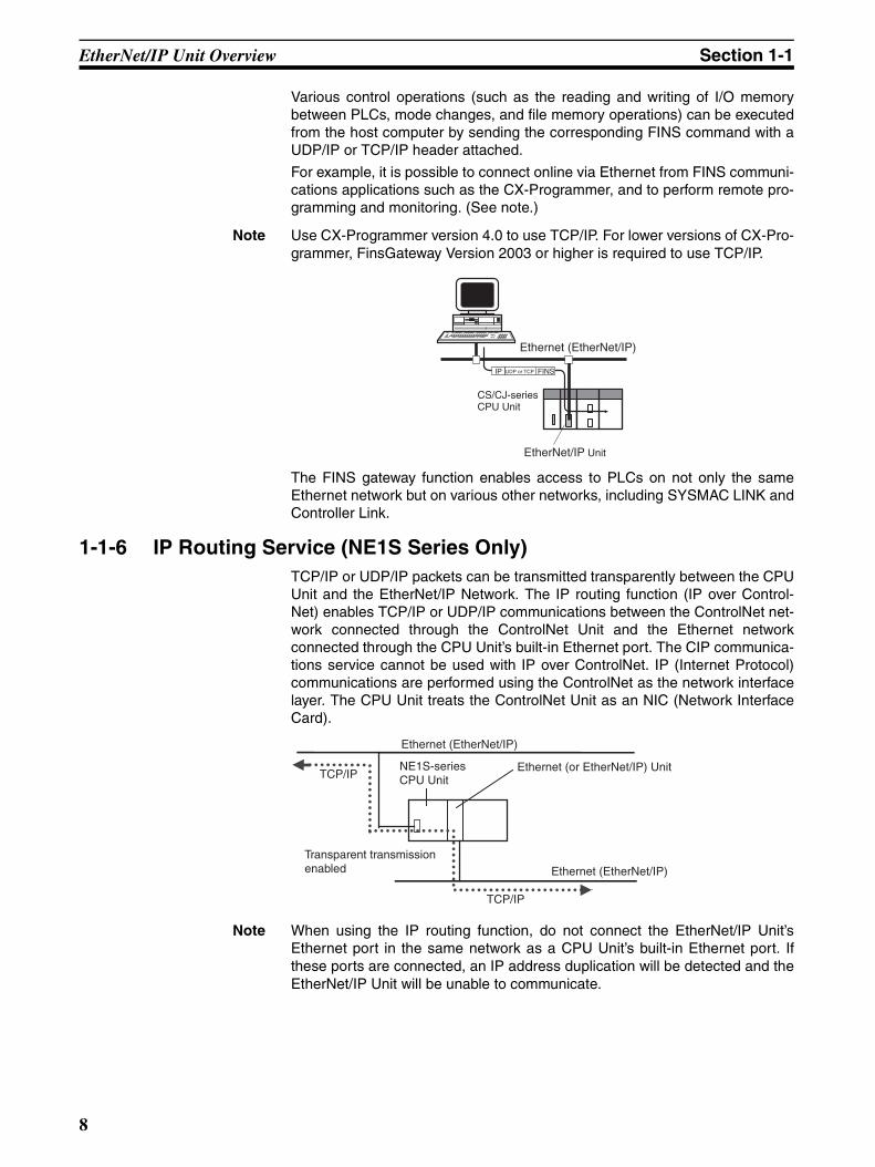
Various control operations (such as the reading and writing of I/O memorybetween PLCs, mode changes, and file memory operations) can be executedfrom the host computer by sending the corresponding FINS command with aUDP/IP or TCP/IP header attached.
For example, it is possible to connect online via Ethernet from FINS communi-cations applications such as the CX-Programmer, and to perform remote pro-gramming and monitoring. (See note.)
Note Use CX-Programmer version 4.0 to use TCP/IP. For lower versions of CX-Pro-grammer, FinsGateway Version 2003 or higher is required to use TCP/IP.
The FINS gateway function enables access to PLCs on not only the sameEthernet network but on various other networks, including SYSMAC LINK andController Link.
1-1-6 IP Routing Service (NE1S Series Only)TCP/IP or UDP/IP packets can be transmitted transparently between the CPUUnit and the EtherNet/IP Network. The IP routing function (IP over Control-Net) enables TCP/IP or UDP/IP communications between the ControlNet net-work connected through the ControlNet Unit and the Ethernet networkconnected through the CPU Unit’s built-in Ethernet port. The CIP communica-tions service cannot be used with IP over ControlNet. IP (Internet Protocol)communications are performed using the ControlNet as the network interfacelayer. The CPU Unit treats the ControlNet Unit as an NIC (Network InterfaceCard).
Note When using the IP routing function, do not connect the EtherNet/IP Unit’sEthernet port in the same network as a CPU Unit’s built-in Ethernet port. Ifthese ports are connected, an IP address duplication will be detected and theEtherNet/IP Unit will be unable to communicate.
Ethernet (EtherNet/IP)
EtherNet/IP Unit
IP UDP or TCP FINS
CS/CJ-series CPU Unit
Ethernet (EtherNet/IP)
Ethernet (EtherNet/IP)
TCP/IP
TCP/IP
NE1S-series CPU Unit
Ethernet (or EtherNet/IP) Unit
Transparent transmission enabled
8
EtherNet/IP Unit Specifications Section 1-2
1-2 EtherNet/IP Unit Specifications
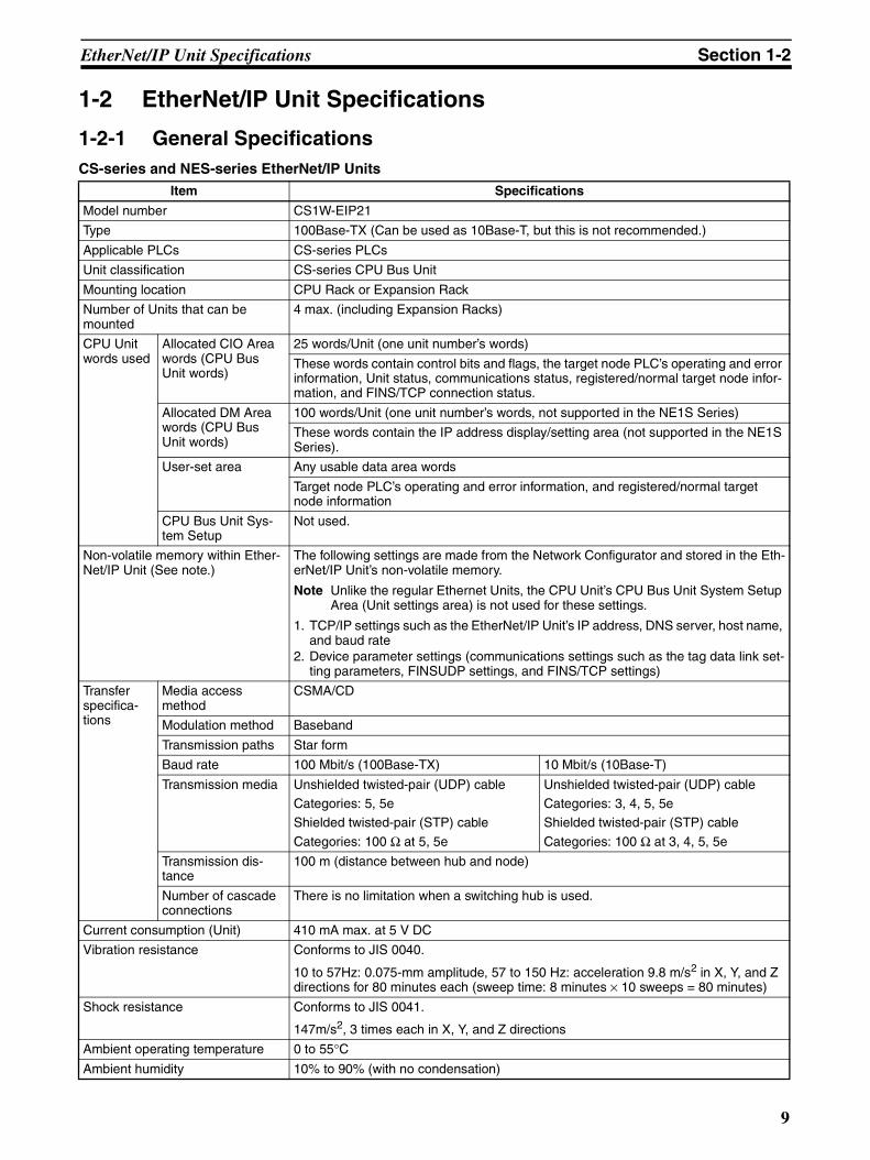
1-2-1 General SpecificationsCS-series and NES-series EtherNet/IP Units
Item Specifications
Model number CS1W-EIP21
Type 100Base-TX (Can be used as 10Base-T, but this is not recommended.)
Applicable PLCs CS-series PLCs
Unit classification CS-series CPU Bus Unit
Mounting location CPU Rack or Expansion Rack
Number of Units that can be mounted
4 max. (including Expansion Racks)
CPU Unit words used
Allocated CIO Area words (CPU Bus Unit words)
25 words/Unit (one unit number’s words)
These words contain control bits and flags, the target node PLC’s operating and error information, Unit status, communications status, registered/normal target node infor-mation, and FINS/TCP connection status.
Allocated DM Area words (CPU Bus Unit words)
100 words/Unit (one unit number’s words, not supported in the NE1S Series)
These words contain the IP address display/setting area (not supported in the NE1S Series).
User-set area Any usable data area words
Target node PLC’s operating and error information, and registered/normal target node information
CPU Bus Unit Sys-tem Setup
Not used.
Non-volatile memory within Ether-Net/IP Unit (See note.)
The following settings are made from the Network Configurator and stored in the Eth-erNet/IP Unit’s non-volatile memory.
Note Unlike the regular Ethernet Units, the CPU Unit’s CPU Bus Unit System Setup Area (Unit settings area) is not used for these settings.
1. TCP/IP settings such as the EtherNet/IP Unit’s IP address, DNS server, host name, and baud rate
2. Device parameter settings (communications settings such as the tag data link set-ting parameters, FINSUDP settings, and FINS/TCP settings)
Transfer specifica-tions
Media access method
CSMA/CD
Modulation method Baseband
Transmission paths Star form
Baud rate 100 Mbit/s (100Base-TX) 10 Mbit/s (10Base-T)
Transmission media Unshielded twisted-pair (UDP) cableCategories: 5, 5eShielded twisted-pair (STP) cable
Categories: 100 Ω at 5, 5e
Unshielded twisted-pair (UDP) cableCategories: 3, 4, 5, 5eShielded twisted-pair (STP) cable
Categories: 100 Ω at 3, 4, 5, 5e
Transmission dis-tance
100 m (distance between hub and node)
Number of cascade connections
There is no limitation when a switching hub is used.
Current consumption (Unit) 410 mA max. at 5 V DC
Vibration resistance Conforms to JIS 0040.
10 to 57Hz: 0.075-mm amplitude, 57 to 150 Hz: acceleration 9.8 m/s2 in X, Y, and Z directions for 80 minutes each (sweep time: 8 minutes × 10 sweeps = 80 minutes)
Shock resistance Conforms to JIS 0041.
147m/s2, 3 times each in X, Y, and Z directions
Ambient operating temperature 0 to 55°CAmbient humidity 10% to 90% (with no condensation)
9
EtherNet/IP Unit Specifications Section 1-2
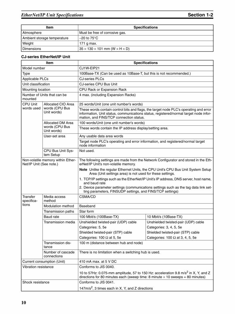
CJ-series EtherNet/IP Unit
Atmosphere Must be free of corrosive gas.
Ambient storage temperature −20 to 75°CWeight 171 g max.
Dimensions 35 × 130 × 101 mm (W × H × D)
Item Specifications
Item Specifications
Model number CJ1W-EIP21
Type 100Base-TX (Can be used as 10Base-T, but this is not recommended.)
Applicable PLCs CJ-series PLCs
Unit classification CJ-series CPU Bus Unit
Mounting location CPU Rack or Expansion Rack
Number of Units that can be mounted
4 max. (including Expansion Racks)
CPU Unit words used
Allocated CIO Area words (CPU Bus Unit words)
25 words/Unit (one unit number’s words)
These words contain control bits and flags, the target node PLC’s operating and error information, Unit status, communications status, registered/normal target node infor-mation, and FINS/TCP connection status.
Allocated DM Area words (CPU Bus Unit words)
100 words/Unit (one unit number’s words)
These words contain the IP address display/setting area.
User-set area Any usable data area words
Target node PLC’s operating and error information, and registered/normal target node information
CPU Bus Unit Sys-tem Setup
Not used.
Non-volatile memory within Ether-Net/IP Unit (See note.)
The following settings are made from the Network Configurator and stored in the Eth-erNet/IP Unit’s non-volatile memory.
Note Unlike the regular Ethernet Units, the CPU Unit’s CPU Bus Unit System Setup Area (Unit settings area) is not used for these settings.
1. TCP/IP settings such as the EtherNet/IP Unit’s IP address, DNS server, host name, and baud rate
2. Device parameter settings (communications settings such as the tag data link set-ting parameters, FINSUDP settings, and FINS/TCP settings)
Transfer specifica-tions
Media access method
CSMA/CD
Modulation method Baseband
Transmission paths Star form
Baud rate 100 Mbit/s (100Base-TX) 10 Mbit/s (10Base-TX)
Transmission media Unshielded twisted-pair (UDP) cableCategories: 5, 5eShielded twisted-pair (STP) cable
Categories: 100 Ω at 5, 5e
Unshielded twisted-pair (UDP) cableCategories: 3, 4, 5, 5eShielded twisted-pair (STP) cable
Categories: 100 Ω at 3, 4, 5, 5e
Transmission dis-tance
100 m (distance between hub and node)
Number of cascade connections
There is no limitation when a switching hub is used.
Current consumption (Unit) 410 mA max. at 5 V DC
Vibration resistance Conforms to JIS 0040.
10 to 57Hz: 0.075-mm amplitude, 57 to 150 Hz: acceleration 9.8 m/s2 in X, Y, and Z directions for 80 minutes each (sweep time: 8 minute × 10 sweeps = 80 minutes)
Shock resistance Conforms to JIS 0041.
147m/s2, 3 times each in X, Y, and Z directions
10

EtherNet/IP Unit Specifications Section 1-2
Ambient operating temperature 0 to 55°CAmbient humidity 10% to 90% (with no condensation)
Atmosphere Must be free of corrosive gas.
Ambient storage temperature −20 to 75°CWeight 94 g max.
Dimensions 31 × 90 × 65 mm (W × H × D)
Item Specifications
11
EtherNet/IP Unit Specifications Section 1-2
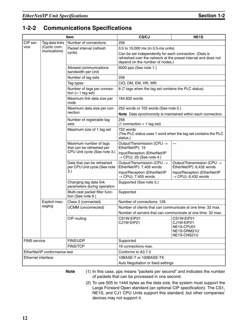
1-2-2 Communications Specifications
Note (1) In this case, pps means “packets per second” and indicates the numberof packets that can be processed in one second.
(2) To use 505 to 1444 bytes as the data size, the system must support theLarge Forward Open standard (an optional CIP specification). The CS1,NE1S, and CJ1 CPU Units support this standard, but other companies’devices may not support it.
Item CS/CJ NE1S
CIP ser-vice
Tag data links (Cyclic com-munications)
Number of connections 256
Packet interval (refresh cycle)
0.5 to 10,000 ms (in 0.5-ms units)
Can be set independently for each connection. (Data is refreshed over the network at the preset interval and does not depend on the number of nodes.)
Allowed communications bandwidth per Unit
6000 pps (See note 1.)
Number of tag sets 256
Tag types CIO, DM, EM, HR, WR
Number of tags per connec-tion (= 1 tag set)
8 (7 tags when the tag set contains the PLC status)
Maximum link data size per node
184,832 words
Maximum data size per con-nection
252 words or 722 words (See note 2.)
Note Data synchronicity is maintained within each connection.
Number of registrable tag sets
256(1 connection = 1 tag set)
Maximum size of 1 tag set 722 words(The PLC status uses 1 word when the tag set contains the PLC status.)
Maximum number of tags that can be refreshed per CPU Unit cycle (See note 3.)
Output/Transmission (CPU → EtherNet/IP): 19Input/Reception (EtherNet/IP → CPU): 20 (See note 4.)
---
Data that can be refreshed per CPU Unit cycle (See note 3.)
Output/Transmission (CPU → EtherNet/IP): 7,405 words
Input/Reception (EtherNet/IP → CPU): 7,405 words
Output/Transmission (CPU → EtherNet/IP): 6,432 words
Input/Reception (EtherNet/IP → CPU): 6,432 words
Changing tag data link parameters during operation
Supported (See note 5.)
Multi-cast packet filter func-tion (See note 6.)
Supported
Explicit mes-saging
Class 3 (connected) Number of connections: 128
UCMM (unconnected) Number of clients that can communicate at one time: 32 max.Number of servers that can communicate at one time: 32 max.
CIP routing CS1W-EIP21CJ1W-EIP21
CS1W-EIP21CJ1W-EIP21NE1S-CPU01NE1S-DRM21UNE1S-CNS21U
FINS service FINS/UDP Supported
FINS/TCP 16 connections max.
EtherNet/IP conformance test Conforms to A3.7.3
Ethernet interface 10BASE-T or 100BASE-TX Auto Negotiation or fixed settings
12

EtherNet/IP Unit Specifications Section 1-2
(3) If the maximum data size is exceeded, the data refreshing with the CPUUnit will extend over two or more cycles.
(4) If status layout is selected in the user settings, the maximum number oftags that can be received is 19 tags.
(5) If parameters are changed, the target EtherNet/IP Unit will restart. Whenother nodes communicating with the target node, the affected data willtemporarily time-out and automatically recover later.
(6) Since the EtherNet/IP Unit is equipped with an IGMP client, unnecessarymulti-cast packets can be filtered by using a switching hub that supportsIGMP snooping.
1-2-3 DimensionsCS1W-EIP21
CJ1W-EIP21
100.5 mm
130 mm
34.5 m
UNIT NO.
× 161 × 16
0
0
1 0
NODE NO.
100BASE-TX10BASE-T
IP ADDRESS 192.168.250.1
SUBNET MASK 255.255.255.0
MS NS
COMM 100M 10M
EIP21
90 mm
65 mm31 mm
EIEIP2P21 1
100BASE-TX10BASE-T
X161
NODENO.
IP ADDRESS192.168.250.1
SUBNET MASK 255.255.255.0
X160
UNITNO.
MS
NS
COMM
100M
10M
13
Nomenclature and Functions Section 1-3
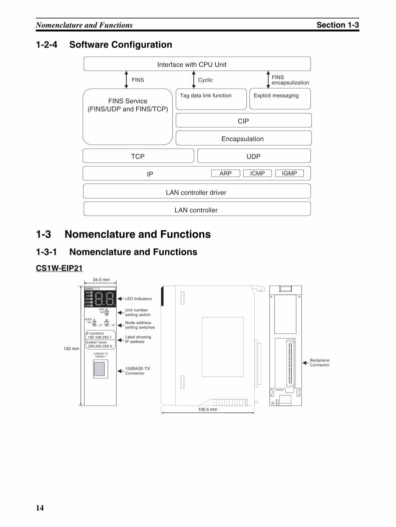
1-2-4 Software Configuration
1-3 Nomenclature and Functions
1-3-1 Nomenclature and Functions
CS1W-EIP21
UDP
IP ARP IGMP
LAN controller driver
LAN controller
Encapsulation
ICMP
TCP
FINS Service(FINS/UDP and FINS/TCP)
Interface with CPU Unit
FINS encapsulizationFINS
CIP
Cyclic
Tag data link function Explicit messaging
UNIT NO.
× 161 × 160
LED Indicators
Unit numbersetting switch
0
1 0
NODE NO.
100BASE-TX10BASE-T
IP ADDRESS192.168.250.1
SUBNET MASK 255.255.255.0
MS NS
COMM 100M 10M
EIP21
130 mm
34.5 mm
100.5 mm
Label showingIP address
Node addresssetting switches
100BASE-TXConnector
BackplaneConnector
14

Nomenclature and Functions Section 1-3
CJ1W-EIP21
Indicators The EtherNet/IP Units are equipped with the following indicators that indicatethe operating status of the node itself and the overall network.
1,2,3... 1. Two two-color status indicators (two-color: green or red LEDs)
2. Three one-color Ethernet indicators (yellow LEDs)
3. A two-digit, 7-segment display
4. Two dot indicators
Status Indicators: MS, NS, COMM, 100M, and 10M
The MS (Module Status) indicator indicates the status of the node itself andthe NS (Network Status) indicator indicates the status of the network.
The COMM, 100M, and 10M indicators indicate the status of Ethernet com-munications.
The MS and NS indicators can be green or red. The COMM, 100M, and 10Mindicators are yellow. These indicators can be lit, flashing, or not lit. The fol-lowing table shows the meaning of these indicator conditions.
Refer to ???Section 13 Error Processing and Maintenance for details on usingthese indicators for troubleshooting.
EIEIP21 P21
100BASE-TX10BASE-T
X161
NODENO.
IP ADDRESS192.168.250.1
SUBNET MASK 255.255.255.0
X160
UNITNO.
MS
NS
COMM
100M
10M
90 mm
31 mm 65 mm
LED Indicators
Unit numbersetting switch
Label showingIP address
Node addresssetting switches
100BASE-TXConnector
MS
A
B
Three LEDs
Two-digit, 7-segment display
Two dot indicators
Indicator Name Color LED status Indicated operating status
MS Module Red Lit Fatal error
Flashing Recoverable error
Green Lit Normal
--- Not lit Power supply OFF
NS Network Red Lit Fatal error
Flashing Recoverable error
Green Lit Tag data link and message connections established
Flashing Tag data link and message connections not established
--- Not lit Offline or power supply OFF
15
Nomenclature and Functions Section 1-3
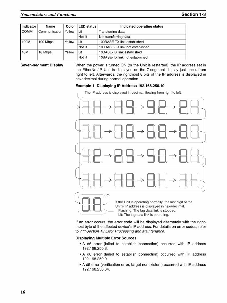
Seven-segment Display When the power is turned ON (or the Unit is restarted), the IP address set inthe EtherNet/IP Unit is displayed on the 7-segment display just once, fromright to left. Afterwards, the rightmost 8 bits of the IP address is displayed inhexadecimal during normal operation.
Example 1: Displaying IP Address 192.168.250.10
If an error occurs, the error code will be displayed alternately with the right-most byte of the affected device’s IP address. For details on error codes, referto ???Section 13 Error Processing and Maintenance.
Displaying Multiple Error Sources
• A d6 error (failed to establish connection) occurred with IP address192.168.250.8.
• A d6 error (failed to establish connection) occurred with IP address192.168.250.9.
• A d5 error (verification error, target nonexistent) occurred with IP address192.168.250.64.
COMM Communication Yellow Lit Transferring data
Not lit Not transferring data
100M 100 Mbps Yellow Lit 100BASE-TX link established
Not lit 100BASE-TX link not established
10M 10 Mbps Yellow Lit 10BASE-TX link established
Not lit 10BASE-TX link not established
Indicator Name Color LED status Indicated operating status
The IP address is displayed in decimal, flowing from right to left.
If the Unit is operating normally, the last digit of the Unit's IP address is displayed in hexadecimal.
Flashing: The tag data link is stopped.Lit: The tag data link is operating.
16

Nomenclature and Functions Section 1-3
• A C6 error (multiple switches ON) and EA error (EtherNet/IP expansionsetting error) occurred with IP address 192.168.250.10.
• There is no particular priority to the order in which the errors are dis-played. All of the errors are displayed repeatedly in order.
Right and Left Dot LEDs
If an error occurred in two or more devices with the same rightmost byte intheir IP addresses, the Right Dot LED will be lit while the devices’ error isbeing displayed.
Example: Displaying the Following Errors
• A d6 error (failed to establish connection) occurred with IP address10.0.1.8.
• A d6 error (failed to establish connection) occurred with IP address10.0.2.8.
The error code is displayed and then the last digit of the target node'sIP address is displayed in hexadecimal.
Displays errors that occurredwithin the Unit.
The last digit of the Unit's IP addressis displayed in hexadecimal.
17
Nomenclature and Functions Section 1-3
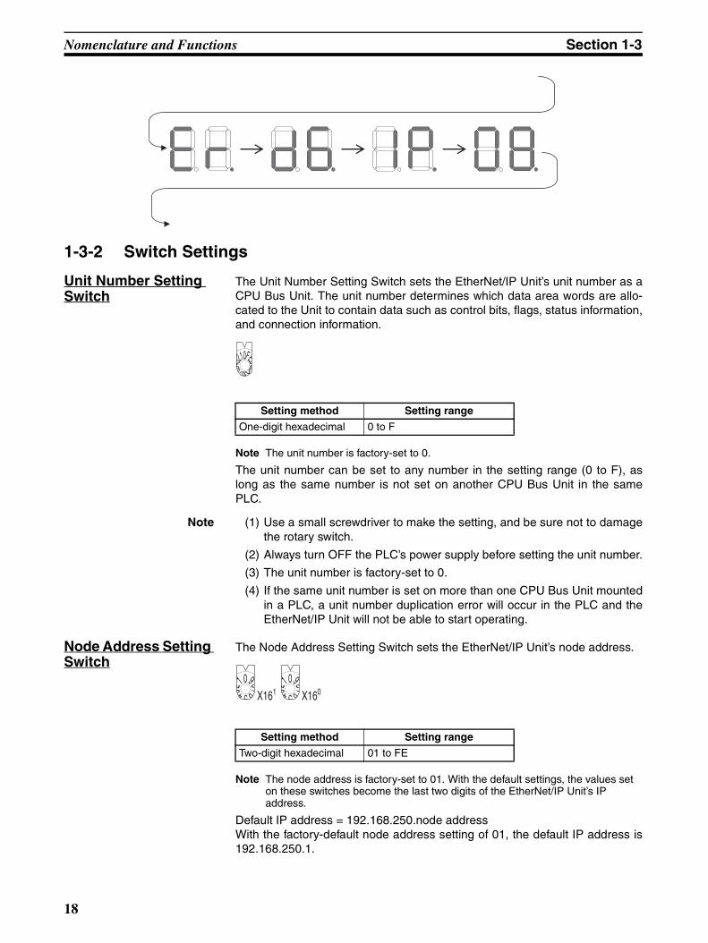
1-3-2 Switch Settings
Unit Number Setting Switch
The Unit Number Setting Switch sets the EtherNet/IP Unit’s unit number as aCPU Bus Unit. The unit number determines which data area words are allo-cated to the Unit to contain data such as control bits, flags, status information,and connection information.
Note The unit number is factory-set to 0.
The unit number can be set to any number in the setting range (0 to F), aslong as the same number is not set on another CPU Bus Unit in the samePLC.
Note (1) Use a small screwdriver to make the setting, and be sure not to damagethe rotary switch.
(2) Always turn OFF the PLC’s power supply before setting the unit number.
(3) The unit number is factory-set to 0.
(4) If the same unit number is set on more than one CPU Bus Unit mountedin a PLC, a unit number duplication error will occur in the PLC and theEtherNet/IP Unit will not be able to start operating.
Node Address Setting Switch
The Node Address Setting Switch sets the EtherNet/IP Unit’s node address.
Note The node address is factory-set to 01. With the default settings, the values set on these switches become the last two digits of the EtherNet/IP Unit’s IP address.
Default IP address = 192.168.250.node addressWith the factory-default node address setting of 01, the default IP address is192.168.250.1.
Setting method Setting range
One-digit hexadecimal 0 to F
FEDCBA9876543210
Setting method Setting range
Two-digit hexadecimal 01 to FE
X16198765432
10
X16098765432
10
18
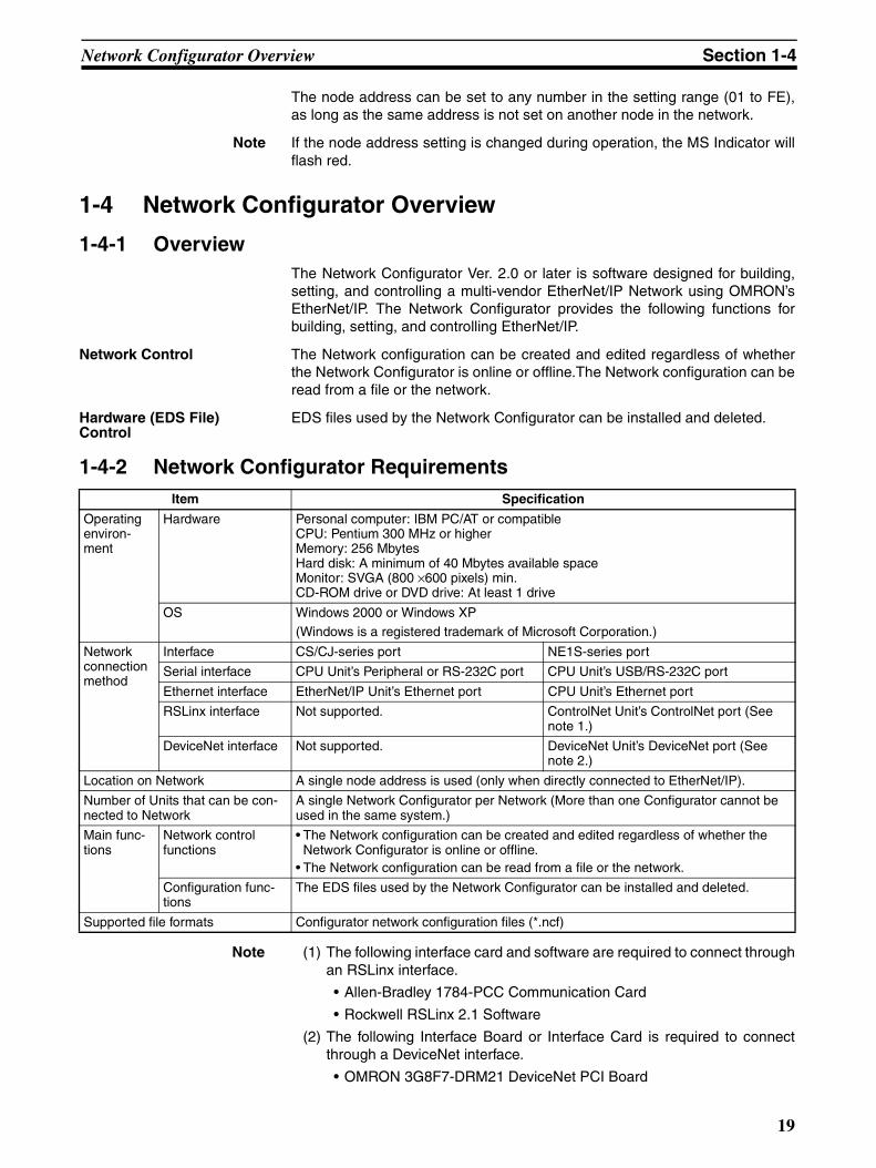
Network Configurator Overview Section 1-4
The node address can be set to any number in the setting range (01 to FE),as long as the same address is not set on another node in the network.
Note If the node address setting is changed during operation, the MS Indicator willflash red.
1-4 Network Configurator Overview
1-4-1 OverviewThe Network Configurator Ver. 2.0 or later is software designed for building,setting, and controlling a multi-vendor EtherNet/IP Network using OMRON’sEtherNet/IP. The Network Configurator provides the following functions forbuilding, setting, and controlling EtherNet/IP.
Network Control The Network configuration can be created and edited regardless of whetherthe Network Configurator is online or offline.The Network configuration can beread from a file or the network.
Hardware (EDS File) Control
EDS files used by the Network Configurator can be installed and deleted.
1-4-2 Network Configurator Requirements
Note (1) The following interface card and software are required to connect throughan RSLinx interface.
• Allen-Bradley 1784-PCC Communication Card
• Rockwell RSLinx 2.1 Software
(2) The following Interface Board or Interface Card is required to connectthrough a DeviceNet interface.
• OMRON 3G8F7-DRM21 DeviceNet PCI Board
Item Specification
Operating environ-ment
Hardware Personal computer: IBM PC/AT or compatibleCPU: Pentium 300 MHz or higherMemory: 256 MbytesHard disk: A minimum of 40 Mbytes available spaceMonitor: SVGA (800 ×600 pixels) min.CD-ROM drive or DVD drive: At least 1 drive
OS Windows 2000 or Windows XP(Windows is a registered trademark of Microsoft Corporation.)
Network connection method
Interface CS/CJ-series port NE1S-series port
Serial interface CPU Unit’s Peripheral or RS-232C port CPU Unit’s USB/RS-232C port
Ethernet interface EtherNet/IP Unit’s Ethernet port CPU Unit’s Ethernet port
RSLinx interface Not supported. ControlNet Unit’s ControlNet port (See note 1.)
DeviceNet interface Not supported. DeviceNet Unit’s DeviceNet port (See note 2.)
Location on Network A single node address is used (only when directly connected to EtherNet/IP).
Number of Units that can be con-nected to Network
A single Network Configurator per Network (More than one Configurator cannot be used in the same system.)
Main func-tions
Network control functions
• The Network configuration can be created and edited regardless of whether the Network Configurator is online or offline.
• The Network configuration can be read from a file or the network.
Configuration func-tions
The EDS files used by the Network Configurator can be installed and deleted.
Supported file formats Configurator network configuration files (*.ncf)
19
Network Configurator Overview Section 1-4
• OMRON 3G8F5-DRM21 DeviceNet ISA Board
• OMRON 3G8E2-DRM21 DeviceNet PCMCIA Card
1-4-3 Precautions When Using the Network ConfiguratorOnly an OMRON EtherNet/IP Unit can be set as the originator for a connec-tion using the Network Configurator.
• The Network Configurator can be connected to the EtherNet/IP networkthrough the following ports:
• CS/CJ-series CPU Unit’s serial port (peripheral or RS-232C)
• NE1S-series CPU Unit’s serial port (USB or RS-232C) or Ethernetport
• NE1S-series DeviceNet Unit’s DeviceNet port(One of the following Interface Boards or Cards is required to connectthrough DeviceNet: 3G8F7-DRM21 DeviceNet PCI Board, 3G8F5-DRM21 DeviceNet ISA Board, or 3G8E2-DRM21 DeviceNet PCMCIACard.)
• NE1S-series ControlNet Unit’s ControlNet port (See note 2.)(The following interface card and software are required to connectthrough an RSLinx interface: an Allen-Bradley 1784-PCC Communi-cation Card and a Rockwell RSLinx 2.1 Software.)
• The Network Configurator can be connected directly to the EtherNet/IPnetwork from the computer’s Ethernet port. When connecting directly tothe EtherNet/IP network, an Ethernet port must be set up in the computerin advance. In this case, the Network Configurator will be connected tothe EtherNet/IP network as a single node. If there isn’t an unused nodeaddress available, the Network Configurator can’t be connected directly tothe EtherNet/IP network.
20

SECTION 2Designing the EtherNet/IP System
This section describes how to design an EtherNet/IP system.
2-1 Design Procedures. . . . . . . . . . . . . . . . . . . . . . . . . . . . . . . . . . . . . . . . . . . . . . 22
2-1-1 Establishing a New EtherNet/IP System . . . . . . . . . . . . . . . . . . . . . 22
2-1-2 Modifying an Established EtherNet/IP System . . . . . . . . . . . . . . . . 24
2-2 Selecting the Network Devices . . . . . . . . . . . . . . . . . . . . . . . . . . . . . . . . . . . . 27
2-2-1 Recommended Network Devices . . . . . . . . . . . . . . . . . . . . . . . . . . . 27
2-2-2 Switching Hub Types . . . . . . . . . . . . . . . . . . . . . . . . . . . . . . . . . . . . 28
2-2-3 Switching Hub Functions . . . . . . . . . . . . . . . . . . . . . . . . . . . . . . . . . 28
2-2-4 Precautions When Selecting a Switching Hub . . . . . . . . . . . . . . . . . 28
2-3 Checking Bandwidth Usage and Adjusting the Packet Interval (RPI) . . . . . . 30
2-3-1 Checking the Tag Data Links’ Bandwidth Usage. . . . . . . . . . . . . . . 31
2-3-2 Checking the Device Bandwidth Usage and Resetting the RPI . . . . 32
2-3-3 Packet Interval (RPI) Setting Examples . . . . . . . . . . . . . . . . . . . . . . 37
21
Design Procedures Section 2-1
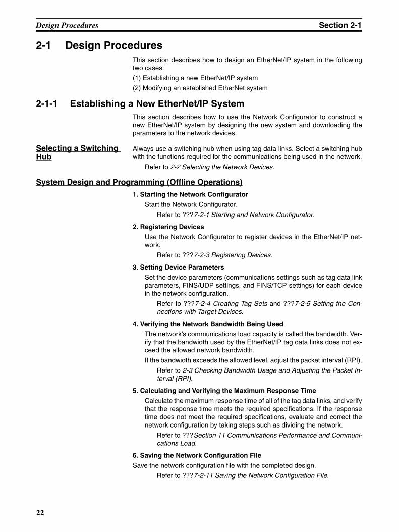
2-1 Design ProceduresThis section describes how to design an EtherNet/IP system in the followingtwo cases.
(1) Establishing a new EtherNet/IP system
(2) Modifying an established EtherNet system
2-1-1 Establishing a New EtherNet/IP SystemThis section describes how to use the Network Configurator to construct anew EtherNet/IP system by designing the new system and downloading theparameters to the network devices.
Selecting a Switching Hub
Always use a switching hub when using tag data links. Select a switching hubwith the functions required for the communications being used in the network.
Refer to 2-2 Selecting the Network Devices.
System Design and Programming (Offline Operations)1. Starting the Network Configurator
Start the Network Configurator.
Refer to ???7-2-1 Starting and Network Configurator.
2. Registering Devices
Use the Network Configurator to register devices in the EtherNet/IP net-work.
Refer to ???7-2-3 Registering Devices.
3. Setting Device Parameters
Set the device parameters (communications settings such as tag data linkparameters, FINS/UDP settings, and FINS/TCP settings) for each devicein the network configuration.
Refer to ???7-2-4 Creating Tag Sets and ???7-2-5 Setting the Con-nections with Target Devices.
4. Verifying the Network Bandwidth Being Used
The network’s communications load capacity is called the bandwidth. Ver-ify that the bandwidth used by the EtherNet/IP tag data links does not ex-ceed the allowed network bandwidth.
If the bandwidth exceeds the allowed level, adjust the packet interval (RPI).
Refer to 2-3 Checking Bandwidth Usage and Adjusting the Packet In-terval (RPI).
5. Calculating and Verifying the Maximum Response Time
Calculate the maximum response time of all of the tag data links, and verifythat the response time meets the required specifications. If the responsetime does not meet the required specifications, evaluate and correct thenetwork configuration by taking steps such as dividing the network.
Refer to ???Section 11 Communications Performance and Communi-cations Load.
6. Saving the Network Configuration File
Save the network configuration file with the completed design.
Refer to ???7-2-11 Saving the Network Configuration File.
22
Design Procedures Section 2-1
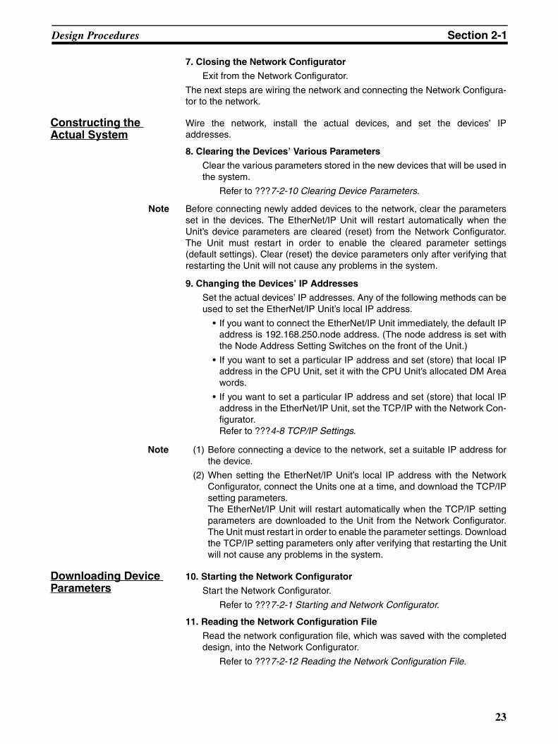
7. Closing the Network Configurator
Exit from the Network Configurator.
The next steps are wiring the network and connecting the Network Configura-tor to the network.
Constructing the Actual System
Wire the network, install the actual devices, and set the devices’ IPaddresses.
8. Clearing the Devices’ Various Parameters
Clear the various parameters stored in the new devices that will be used inthe system.
Refer to ???7-2-10 Clearing Device Parameters.
Note Before connecting newly added devices to the network, clear the parametersset in the devices. The EtherNet/IP Unit will restart automatically when theUnit’s device parameters are cleared (reset) from the Network Configurator.The Unit must restart in order to enable the cleared parameter settings(default settings). Clear (reset) the device parameters only after verifying thatrestarting the Unit will not cause any problems in the system.
9. Changing the Devices’ IP Addresses
Set the actual devices’ IP addresses. Any of the following methods can beused to set the EtherNet/IP Unit’s local IP address.
• If you want to connect the EtherNet/IP Unit immediately, the default IPaddress is 192.168.250.node address. (The node address is set withthe Node Address Setting Switches on the front of the Unit.)
• If you want to set a particular IP address and set (store) that local IPaddress in the CPU Unit, set it with the CPU Unit’s allocated DM Areawords.
• If you want to set a particular IP address and set (store) that local IPaddress in the EtherNet/IP Unit, set the TCP/IP with the Network Con-figurator.Refer to ???4-8 TCP/IP Settings.
Note (1) Before connecting a device to the network, set a suitable IP address forthe device.
(2) When setting the EtherNet/IP Unit’s local IP address with the NetworkConfigurator, connect the Units one at a time, and download the TCP/IPsetting parameters.The EtherNet/IP Unit will restart automatically when the TCP/IP settingparameters are downloaded to the Unit from the Network Configurator.The Unit must restart in order to enable the parameter settings. Downloadthe TCP/IP setting parameters only after verifying that restarting the Unitwill not cause any problems in the system.
Downloading Device Parameters
10. Starting the Network Configurator
Start the Network Configurator.
Refer to ???7-2-1 Starting and Network Configurator.
11. Reading the Network Configuration File
Read the network configuration file, which was saved with the completeddesign, into the Network Configurator.
Refer to ???7-2-12 Reading the Network Configuration File.
23
Design Procedures Section 2-1
12. Verifying the IP Addresses
Verify that the devices’ IP addresses in the network configuration filematches the actual devices’ IP addresses. If one of the IP addresses doesnot match, change the IP address so that it matches.
Refer to ???4-8 TCP/IP Settings.
13. Connecting the Network Configurator to the Network
Connect the Network Configurator to the CPU Unit through the serial portor Ethernet interface.
Refer to ???7-2-6 Connecting the Network Configurator to the Net-work.
14. Downloading the Device Parameters
Download the parameters to all of the devices in the network.
Refer to ???7-2-7 Downloading Tag Data Link Parameters.
15. Verifying the Downloaded Device Parameters
Compare the parameters in all of the devices in the network, to verify thatthe user-set device parameters were properly downloaded and saved inthe devices.
Refer to ???7-2-9 Comparing the Tag Data Link Parameters.
16. Closing the Network Configurator
Exit from the Network Configurator.
Note (1) The EtherNet/IP Unit will restart automatically when the device parame-ters are downloaded to the Unit from the Network Configurator. The Unitmust restart in order to enable the parameter settings. Download the de-vice parameters only after verifying that restarting the Unit will not causeany problems in the system.
(2) After the device parameters have been downloaded, compare the param-eters and verify that the saved parameters are correct.
(3) Before operating the actual system, always verify that the devices in thenetwork are operating as expected in the system design.
Actual System Operation
17. Operating the Actual System
Start operating the system.
2-1-2 Modifying an Established EtherNet/IP SystemThis section describes how to change an EtherNet/IP system after the systemhas started operating.
Uploading and Saving the System’s Network Configuration
1. Stopping the System
Take steps, such as stopping the CPU Unit’s program, so that device pa-rameter changes will not affect the system.
2. Starting the Network Configurator and Connecting to the Network
Start the Network Configurator and connect it to the network via the CPUUnit’s serial port or an Ethernet interface.
Refer to ???7-2-1 Starting the Network Configurator and ???7-2-6Connecting the Network Configurator to the Network.
3. Uploading the Network Configuration
Upload the network information to collect the current network configura-tion.
24
Design Procedures Section 2-1
Refer to ???7-2-8 Uploading Tag Data Link Parameters.
4. Saving the Network Configuration File
Save a network configuration file containing all of the devices’ verified pa-rameters.
Refer to ???7-2-11 Saving the Network Configuration File.
5. Closing the Network Configurator
Exit from the Network Configurator.
Changing the Actual System Configuration
Refer to the modified specifications and make the necessary changes, suchas changing network wiring, changing IP addresses, adding devices, anddeleting devices.
6. Clearing Parameters in Added Devices
Clear the various parameters stored in the added devices.
Refer to ???7-2-10 Clearing Device Parameters.
Note Before connecting newly added devices to the network, clear the parametersset in the devices. The EtherNet/IP Unit will restart automatically when theUnit’s device parameters are cleared (reset) from the Network Configurator.The Unit must restart in order to enable the cleared parameter settings(default settings). Clear (reset) the device parameters only after verifying thatrestarting the Unit will not cause any problems in the system.
7. Changing the Devices’ IP Addresses
Set the IP addresses of the added devices.
• If you want to connect the EtherNet/IP Unit immediately, the default IPaddress is 192.168.250.node address. (The node address is set withthe Node Address Setting Switches on the front of the Unit.)
• If you want to set a particular IP address and set (store) that local IPaddress in the CPU Unit, set it with the CPU Unit’s allocated DM Areawords.
• If you want to set a particular IP address and set (store) that local IPaddress in the EtherNet/IP Unit, set the TCP/IP with the Network Con-figurator.Refer to ???4-8 TCP/IP Settings.
Note (1) Before connecting a device to the network, set a suitable IP address.
(2) When setting the EtherNet/IP Unit’s local IP address with the NetworkConfigurator, connect the Units one at a time, and download the TCP/IPsetting parameters.The EtherNet/IP Unit will restart automatically when the TCP/IP settingparameters are downloaded to the Unit from the Network Configurator.The Unit must restart in order to enable the parameter settings. Downloadthe TCP/IP setting parameters only after verifying that restarting the Unitwill not cause any problems in the system.
Changing Device Parameters
8. Starting the Network Configurator
Start the Network Configurator to redesign the network.
9. Reading the Network Configuration File
Read the previously saved network configuration file.
Refer to ???7-2-12 Reading the Network Configuration File.
25
Design Procedures Section 2-1
10. Changing the Network Configuration
Make the changes required in the system redesign, such as adding devic-es, deleting devices, and changing IP addresses.
Refer to ???4-8 TCP/IP Settings.
11. Changing the Device Parameters
Change the device parameters for each device in the network configura-tion, as required in the system redesign.
Refer to ???7-2-4 Creating Tag Sets and ???7-2-5 Setting the Con-nections with Target Devices.
12. Verifying the Network Bandwidth Being Used
Verify that the bandwidth used by the EtherNet/IP tag data links does notexceed the allowed network bandwidth.
If the bandwidth exceeds the allowed level, adjust the packet interval (RPI).
Refer to ???2-3 Checking Bandwidth Usage and Adjusting the PacketInterval (RPI).
13. Recalculating and Verifying the Maximum Response Time
Calculate the maximum response time of all of the tag data links, and verifythat the response time meets the design requirements. If the responsetime does not meet the required specifications, evaluate and correct thenetwork configuration by taking steps such as using a different switchinghub or dividing the network.
Refer to 2-2 Selecting the Network Devices.
Refer to ???Section 11 Communications Performance and Communi-cations Load.
14. Saving the Network Configuration File
Save the modified network configuration file.
Refer to ???7-2-11 Saving the Network Configuration File.
15. Closing the Network Configurator
Exit from the Network Configurator.
The next steps are completing the changes in the actual system and con-necting the Network Configurator to the network.
Note Changing Target Device ParametersIf the target device parameters are changed, they will no longer agree with theparameter information registered in the originator device where the targetdevice is registered. A yellow bar will be displayed next to the target deviceicon to indicate when this occurs. Open the Edit Device Parameters Dialog Box and check target device infor-mation.
Downloading the Changed Device Parameters
16. Reading the Network Configuration File
Read the network configuration file, which was saved with the completeddesign.
Refer to ???7-2-12 Reading the Network Configuration File.
17. Starting the Network Configurator and Connecting to the Network
Start the Network Configurator and connect it to the network via the CPUUnit’s serial port or an Ethernet interface.
Refer to ???7-2-1 Starting the Network Configurator and ???7-2-6Connecting the Network Configurator to the Network.
26
Selecting the Network Devices Section 2-2
18. Downloading the Device Parameters
Download the parameters to all of the devices.
Refer to ???7-2-7 Downloading Tag Data Link Parameters.
19. Verifying the Downloaded Device Parameters
Compare the parameters in all of the devices, to verify that the user-set de-vice parameters were properly downloaded and saved in the devices.
Refer to ???7-2-9 Comparing the Tag Data Link Parameters.
20. Closing the Network Configurator
Exit from the Network Configurator.
Note (1) The EtherNet/IP Unit will restart automatically when the device parame-ters are downloaded to the Unit from the Network Configurator. The Unitmust restart in order to enable the parameter settings. Download the de-vice parameters only after verifying that restarting the Unit will not causeany problems in the system.
(2) After the device parameters have been downloaded, compare the param-eters and verify that the saved parameters are correct.
(3) Before operating the actual system, always verify that the devices in thenetwork are operating as expected in the system design.
Restarting Actual System Operation
21. Operating the Actual System
Start operating the system.
2-2 Selecting the Network Devices
2-2-1 Recommended Network DevicesThe following table shows the devices recommended for use with the Ether-Net/IP Unit.
Part Maker Model number Inquires
Switching Hub
Cisco Systems, Inc. WS-C2955T-12 (12-port switching hub)
Note For use in an FA environment
Cisco Systems, Inc. Main Corpo-rate HQ: (800) 553-6387
Contec USA, Inc. SH-8008(FIT)H CONTEC USA Inc.: (408) 400-8700
Phoenix Contact FL SWITCH SFN 8TX Phoenix Contact USA Customer Service: (800) 808-7177
Twisted-pair cable
100BASE-TX
Fujikura F-LINK-E 0.5mm × 4P Fujikura America, Inc.:(408) 748-6991Specifications: STP cable (shielded,
twisted-pair cable)Category 5 or 5e
Note Impedance up to 100 Ω max.
Fujikura CTP-LAN5 0.5 mm × 4P
Specifications: UTP cable (unshielded, twisted-pair cable)Category 5 or 5e
27
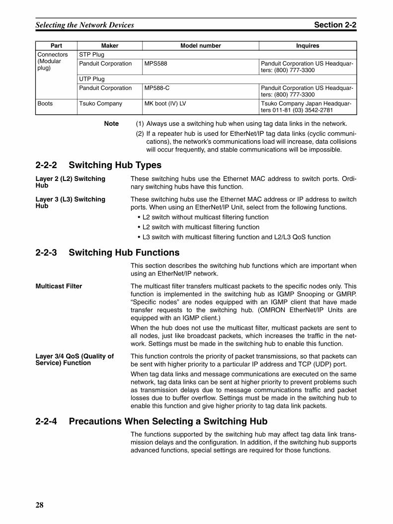
Selecting the Network Devices Section 2-2
Note (1) Always use a switching hub when using tag data links in the network.
(2) If a repeater hub is used for EtherNet/IP tag data links (cyclic communi-cations), the network’s communications load will increase, data collisionswill occur frequently, and stable communications will be impossible.
2-2-2 Switching Hub TypesLayer 2 (L2) Switching Hub
These switching hubs use the Ethernet MAC address to switch ports. Ordi-nary switching hubs have this function.
Layer 3 (L3) Switching Hub
These switching hubs use the Ethernet MAC address or IP address to switchports. When using an EtherNet/IP Unit, select from the following functions.
• L2 switch without multicast filtering function
• L2 switch with multicast filtering function
• L3 switch with multicast filtering function and L2/L3 QoS function
2-2-3 Switching Hub FunctionsThis section describes the switching hub functions which are important whenusing an EtherNet/IP network.
Multicast Filter The multicast filter transfers multicast packets to the specific nodes only. Thisfunction is implemented in the switching hub as IGMP Snooping or GMRP.“Specific nodes” are nodes equipped with an IGMP client that have madetransfer requests to the switching hub. (OMRON EtherNet/IP Units areequipped with an IGMP client.)
When the hub does not use the multicast filter, multicast packets are sent toall nodes, just like broadcast packets, which increases the traffic in the net-work. Settings must be made in the switching hub to enable this function.
Layer 3/4 QoS (Quality of Service) Function
This function controls the priority of packet transmissions, so that packets canbe sent with higher priority to a particular IP address and TCP (UDP) port.
When tag data links and message communications are executed on the samenetwork, tag data links can be sent at higher priority to prevent problems suchas transmission delays due to message communications traffic and packetlosses due to buffer overflow. Settings must be made in the switching hub toenable this function and give higher priority to tag data link packets.
2-2-4 Precautions When Selecting a Switching HubThe functions supported by the switching hub may affect tag data link trans-mission delays and the configuration. In addition, if the switching hub supportsadvanced functions, special settings are required for those functions.
Connectors(Modular plug)
STP Plug
Panduit Corporation MPS588 Panduit Corporation US Headquar-ters: (800) 777-3300
UTP Plug
Panduit Corporation MP588-C Panduit Corporation US Headquar-ters: (800) 777-3300
Boots Tsuko Company MK boot (IV) LV Tsuko Company Japan Headquar-ters 011-81 (03) 3542-2781
Part Maker Model number Inquires
28
Selecting the Network Devices Section 2-2
When selecting a switching hub, it is necessary to consider whether theswitching hub will be selected based on the kind of communications that willbe performed in the network or the kind of switching hub that you want to use.Refer to the following precautions when selecting a switching hub.
Selecting the Switching Hub Based on the Types of Network Communications
Executing Tag Data Links Only
We recommend using an L2 switching hub without multicast filtering or an L2switching hub with multicast filtering.
Using an L2 switching hub with multicast filtering prevents increased trafficdue to unnecessary multicast packets, so the tag data links can operate athigher speed. If either of the following conditions exists, the amount traffic willbe the same for both kinds of L2 switching hubs (with or without multicast fil-tering).
• The tag data links are set to share the same data with all nodes in the net-work. (The multicast packets are transferred to all nodes in the network,just like a broadcast.)
• The tag data link settings are all one-to-one (unicast) and multicast pack-ets cannot be used.
If the multicast filter function is being used, settings must be made for thatfunction in the switching hub.
Executing Tag Data Links and Message Communications
We recommend using an L3 switching hub with multicast filtering and L3/L4QoS.
By setting tag data links for higher-priority transmission, it is possible to pre-vent problems such as transmission delays due to message communicationstraffic and packet losses due to buffer overflow. Settings must be made in theswitching hub to enable this function and give higher priority to tag data linkpackets.
Special settings must be made in the switching hub when using the multicastfiltering function and L3/L4 QoS function.
Selecting the Switching Hub Based on the Hub’s Supported Functions
L2 Switching Hub without Multicast Filtering
We recommend this kind of switching hub when only tag data links are exe-cuted and any of the following conditions is met.
• The tag data links are set to share the same data with all nodes in the net-work. (The multicast packets are transferred to all nodes in the network,just like a broadcast.)
• The tag data link settings are all one-to-one (unicast) and multicast pack-ets cannot be used.
• There is little traffic in the tag data links.
No special settings are required for an L2 switching hub without multicast fil-tering.
L2 Switching Hub with Multicast Filtering
We recommend this kind of switching hub when only tag data links are exe-cuted and the following condition is met.
• There are many 1:N links (where N represents some number of nodes inthe network) in the tag data link settings, i.e., there are many multicastpackets used, or there is heavy traffic in the tag data links.
Special settings are required for an L2 switching hub with multicast filtering.
L3 Switching Hub with Multicast Filtering and L3/L4 QoS Functions
We recommend this kind of switching hub when both tag data links and mes-sage communications are executed.
29
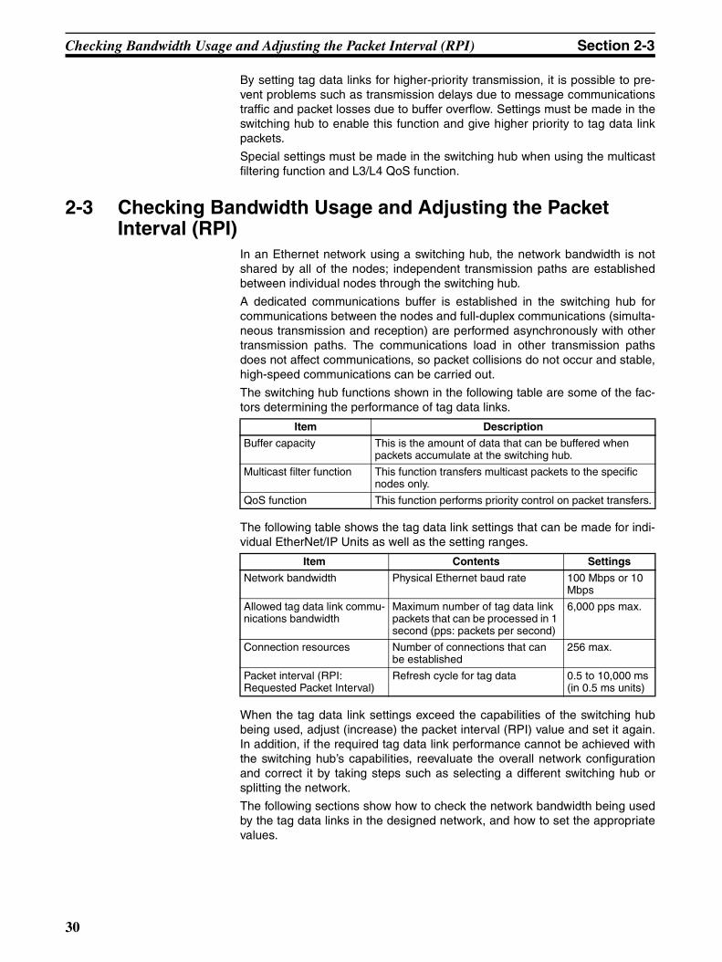
Checking Bandwidth Usage and Adjusting the Packet Interval (RPI) Section 2-3
By setting tag data links for higher-priority transmission, it is possible to pre-vent problems such as transmission delays due to message communicationstraffic and packet losses due to buffer overflow. Settings must be made in theswitching hub to enable this function and give higher priority to tag data linkpackets.
Special settings must be made in the switching hub when using the multicastfiltering function and L3/L4 QoS function.
2-3 Checking Bandwidth Usage and Adjusting the Packet Interval (RPI)
In an Ethernet network using a switching hub, the network bandwidth is notshared by all of the nodes; independent transmission paths are establishedbetween individual nodes through the switching hub.
A dedicated communications buffer is established in the switching hub forcommunications between the nodes and full-duplex communications (simulta-neous transmission and reception) are performed asynchronously with othertransmission paths. The communications load in other transmission pathsdoes not affect communications, so packet collisions do not occur and stable,high-speed communications can be carried out.
The switching hub functions shown in the following table are some of the fac-tors determining the performance of tag data links.
The following table shows the tag data link settings that can be made for indi-vidual EtherNet/IP Units as well as the setting ranges.
When the tag data link settings exceed the capabilities of the switching hubbeing used, adjust (increase) the packet interval (RPI) value and set it again.In addition, if the required tag data link performance cannot be achieved withthe switching hub’s capabilities, reevaluate the overall network configurationand correct it by taking steps such as selecting a different switching hub orsplitting the network.
The following sections show how to check the network bandwidth being usedby the tag data links in the designed network, and how to set the appropriatevalues.
Item Description
Buffer capacity This is the amount of data that can be buffered when packets accumulate at the switching hub.
Multicast filter function This function transfers multicast packets to the specific nodes only.
QoS function This function performs priority control on packet transfers.
Item Contents Settings
Network bandwidth Physical Ethernet baud rate 100 Mbps or 10 Mbps
Allowed tag data link commu-nications bandwidth
Maximum number of tag data link packets that can be processed in 1 second (pps: packets per second)
6,000 pps max.
Connection resources Number of connections that can be established
256 max.
Packet interval (RPI: Requested Packet Interval)
Refresh cycle for tag data 0.5 to 10,000 ms (in 0.5 ms units)
30
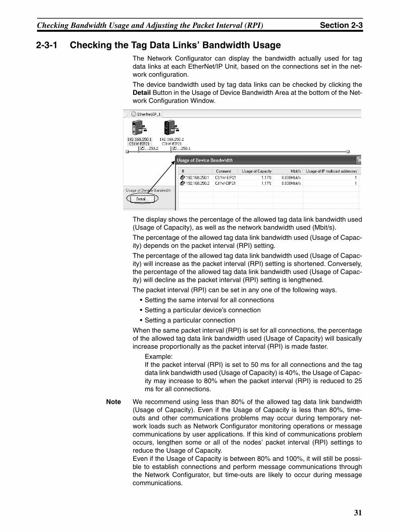
Checking Bandwidth Usage and Adjusting the Packet Interval (RPI) Section 2-3
2-3-1 Checking the Tag Data Links’ Bandwidth UsageThe Network Configurator can display the bandwidth actually used for tagdata links at each EtherNet/IP Unit, based on the connections set in the net-work configuration.
The device bandwidth used by tag data links can be checked by clicking theDetail Button in the Usage of Device Bandwidth Area at the bottom of the Net-work Configuration Window.
The display shows the percentage of the allowed tag data link bandwidth used(Usage of Capacity), as well as the network bandwidth used (Mbit/s).
The percentage of the allowed tag data link bandwidth used (Usage of Capac-ity) depends on the packet interval (RPI) setting.
The percentage of the allowed tag data link bandwidth used (Usage of Capac-ity) will increase as the packet interval (RPI) setting is shortened. Conversely,the percentage of the allowed tag data link bandwidth used (Usage of Capac-ity) will decline as the packet interval (RPI) setting is lengthened.
The packet interval (RPI) can be set in any one of the following ways.
• Setting the same interval for all connections
• Setting a particular device’s connection
• Setting a particular connection
When the same packet interval (RPI) is set for all connections, the percentageof the allowed tag data link bandwidth used (Usage of Capacity) will basicallyincrease proportionally as the packet interval (RPI) is made faster.
Example:If the packet interval (RPI) is set to 50 ms for all connections and the tagdata link bandwidth used (Usage of Capacity) is 40%, the Usage of Capac-ity may increase to 80% when the packet interval (RPI) is reduced to 25ms for all connections.
Note We recommend using less than 80% of the allowed tag data link bandwidth(Usage of Capacity). Even if the Usage of Capacity is less than 80%, time-outs and other communications problems may occur during temporary net-work loads such as Network Configurator monitoring operations or messagecommunications by user applications. If this kind of communications problemoccurs, lengthen some or all of the nodes’ packet interval (RPI) settings toreduce the Usage of Capacity.Even if the Usage of Capacity is between 80% and 100%, it will still be possi-ble to establish connections and perform message communications throughthe Network Configurator, but time-outs are likely to occur during messagecommunications.
31
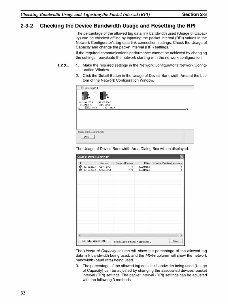
Checking Bandwidth Usage and Adjusting the Packet Interval (RPI) Section 2-3
2-3-2 Checking the Device Bandwidth Usage and Resetting the RPIThe percentage of the allowed tag data link bandwidth used (Usage of Capac-ity) can be checked offline by inputting the packet interval (RPI) values in theNetwork Configurator’s tag data link connection settings. Check the Usage ofCapacity and change the packet interval (RPI) settings.
If the required communications performance cannot be achieved by changingthe settings, reevaluate the network starting with the network configuration.
1,2,3... 1. Make the required settings in the Network Configurator’s Network Config-uration Window.
2. Click the Detail Button in the Usage of Device Bandwidth Area at the bot-tom of the Network Configuration Window.
The Usage of Device Bandwidth Area Dialog Box will be displayed.
The Usage of Capacity column will show the percentage of the allowed tagdata link bandwidth being used, and the Mbit/s column will show the networkbandwidth (baud rate) being used.
3. The percentage of the allowed tag data link bandwidth being used (Usageof Capacity) can be adjusted by changing the associated devices’ packetinterval (RPI) settings. The packet interval (RPI) settings can be adjustedwith the following 3 methods.
32
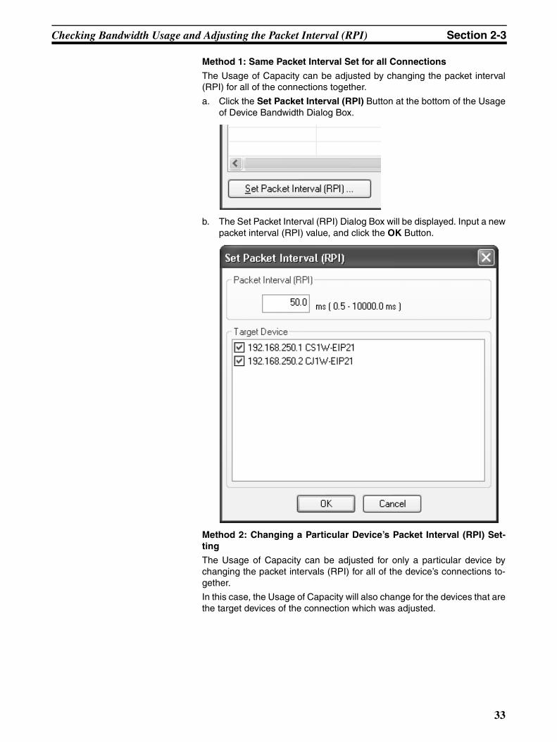
Checking Bandwidth Usage and Adjusting the Packet Interval (RPI) Section 2-3
Method 1: Same Packet Interval Set for all Connections
The Usage of Capacity can be adjusted by changing the packet interval(RPI) for all of the connections together.
a. Click the Set Packet Interval (RPI) Button at the bottom of the Usageof Device Bandwidth Dialog Box.
b. The Set Packet Interval (RPI) Dialog Box will be displayed. Input a newpacket interval (RPI) value, and click the OK Button.
Method 2: Changing a Particular Device’s Packet Interval (RPI) Set-ting
The Usage of Capacity can be adjusted for only a particular device bychanging the packet intervals (RPI) for all of the device’s connections to-gether.
In this case, the Usage of Capacity will also change for the devices that arethe target devices of the connection which was adjusted.
33
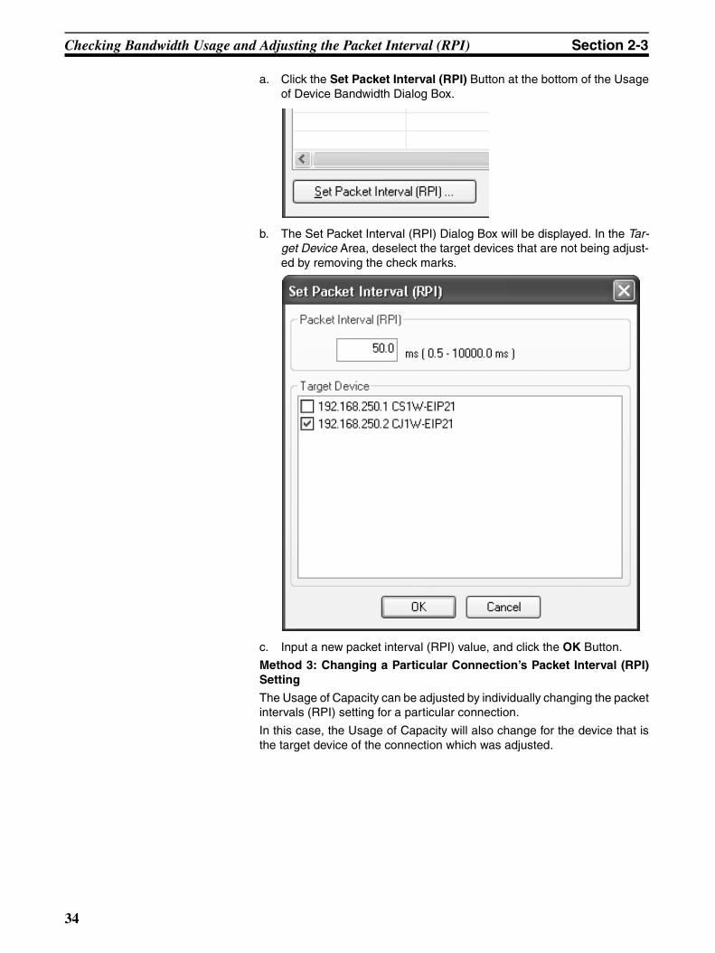
Checking Bandwidth Usage and Adjusting the Packet Interval (RPI) Section 2-3
a. Click the Set Packet Interval (RPI) Button at the bottom of the Usageof Device Bandwidth Dialog Box.
b. The Set Packet Interval (RPI) Dialog Box will be displayed. In the Tar-get Device Area, deselect the target devices that are not being adjust-ed by removing the check marks.
c. Input a new packet interval (RPI) value, and click the OK Button.
Method 3: Changing a Particular Connection’s Packet Interval (RPI)Setting
The Usage of Capacity can be adjusted by individually changing the packetintervals (RPI) setting for a particular connection.
In this case, the Usage of Capacity will also change for the device that isthe target device of the connection which was adjusted.
34
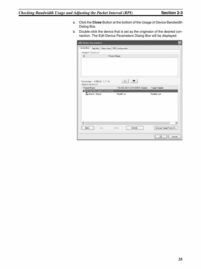
Checking Bandwidth Usage and Adjusting the Packet Interval (RPI) Section 2-3
a. Click the Close Button at the bottom of the Usage of Device BandwidthDialog Box.
b. Double-click the device that is set as the originator of the desired con-nection. The Edit Device Parameters Dialog Box will be displayed.
35
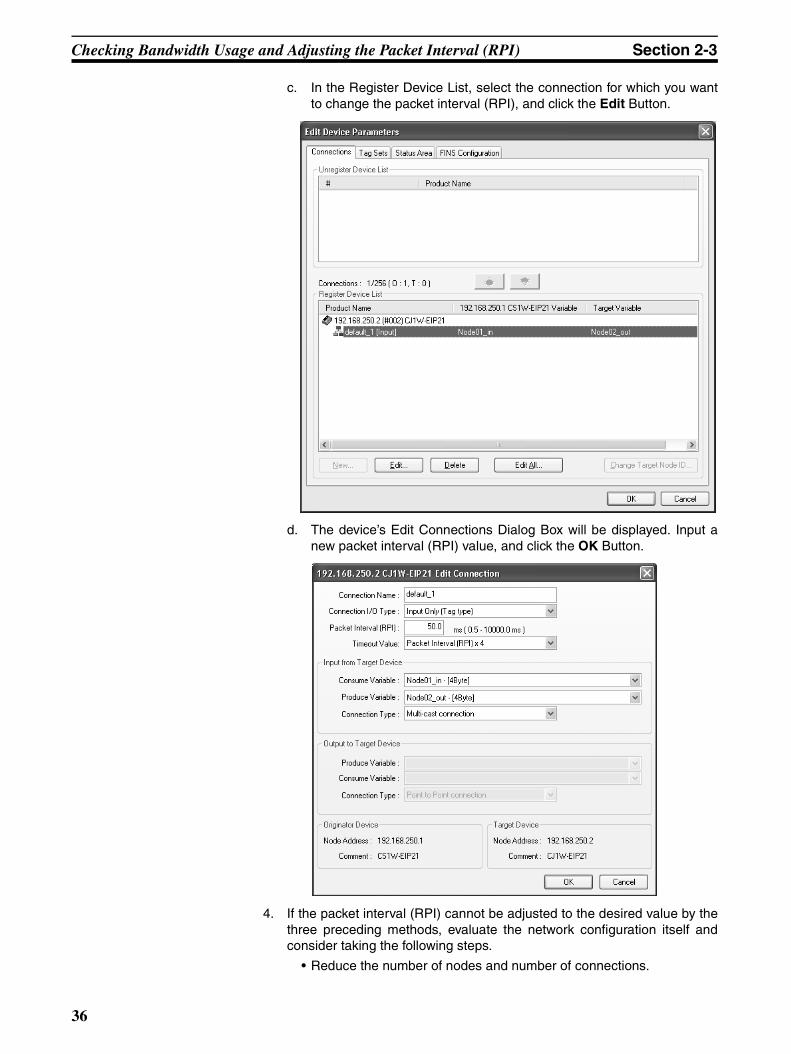
Checking Bandwidth Usage and Adjusting the Packet Interval (RPI) Section 2-3
c. In the Register Device List, select the connection for which you wantto change the packet interval (RPI), and click the Edit Button.
d. The device’s Edit Connections Dialog Box will be displayed. Input anew packet interval (RPI) value, and click the OK Button.
4. If the packet interval (RPI) cannot be adjusted to the desired value by thethree preceding methods, evaluate the network configuration itself andconsider taking the following steps.
• Reduce the number of nodes and number of connections.
36
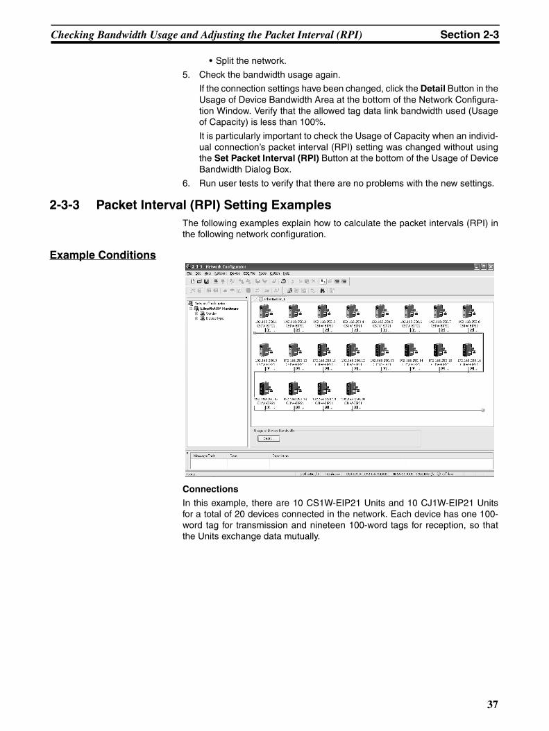
Checking Bandwidth Usage and Adjusting the Packet Interval (RPI) Section 2-3
• Split the network.
5. Check the bandwidth usage again.
If the connection settings have been changed, click the Detail Button in theUsage of Device Bandwidth Area at the bottom of the Network Configura-tion Window. Verify that the allowed tag data link bandwidth used (Usageof Capacity) is less than 100%.
It is particularly important to check the Usage of Capacity when an individ-ual connection’s packet interval (RPI) setting was changed without usingthe Set Packet Interval (RPI) Button at the bottom of the Usage of DeviceBandwidth Dialog Box.
6. Run user tests to verify that there are no problems with the new settings.
2-3-3 Packet Interval (RPI) Setting ExamplesThe following examples explain how to calculate the packet intervals (RPI) inthe following network configuration.
Example Conditions
Connections
In this example, there are 10 CS1W-EIP21 Units and 10 CJ1W-EIP21 Unitsfor a total of 20 devices connected in the network. Each device has one 100-word tag for transmission and nineteen 100-word tags for reception, so thatthe Units exchange data mutually.
37

Checking Bandwidth Usage and Adjusting the Packet Interval (RPI) Section 2-3
By default, the packet intervals (RPI) are set to 50 ms for all of the connec-tions. The devices’ IP addresses range from 192.168.250.1 to192.168.250.20.
Checking the Device Bandwidth Usage
When the Detail Button is clicked in the Usage of Device Bandwidth Area, it isapparent that the percentage of the allowed tag data link bandwidth beingused by each device’s tag data link (Usage of Capacity) is 36.67%, as shownin the following dialog box.
IP address: 192.168.250.1 192.168.250.2 192.168.250.3
CS1W-EIP21 CS1W-EIP21
100 words
100 words
100 words
Transmit
Transmit
Transmit
Transmit
192.168.250.20
CJ1W-EIP21
10 CS1W-EIP21 Units + 10 CJ1W-EIP21 Units = 20 Units totalThe RPI is 10 ms (ethernet default) for all connections.
Tag data link area with 100 words x 20 Units
CS1W-EIP21
100 words
38
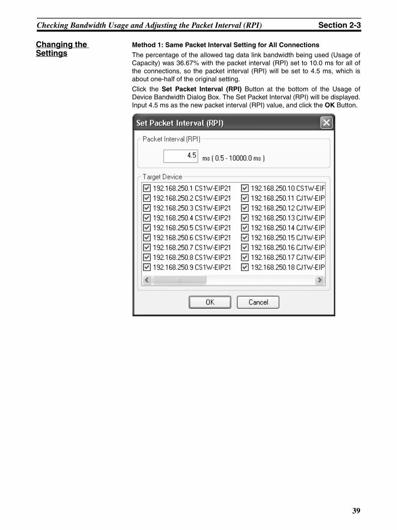
Checking Bandwidth Usage and Adjusting the Packet Interval (RPI) Section 2-3
Changing the Settings
Method 1: Same Packet Interval Setting for All Connections
The percentage of the allowed tag data link bandwidth being used (Usage ofCapacity) was 36.67% with the packet interval (RPI) set to 10.0 ms for all ofthe connections, so the packet interval (RPI) will be set to 4.5 ms, which isabout one-half of the original setting.
Click the Set Packet Interval (RPI) Button at the bottom of the Usage ofDevice Bandwidth Dialog Box. The Set Packet Interval (RPI) will be displayed.Input 4.5 ms as the new packet interval (RPI) value, and click the OK Button.
39
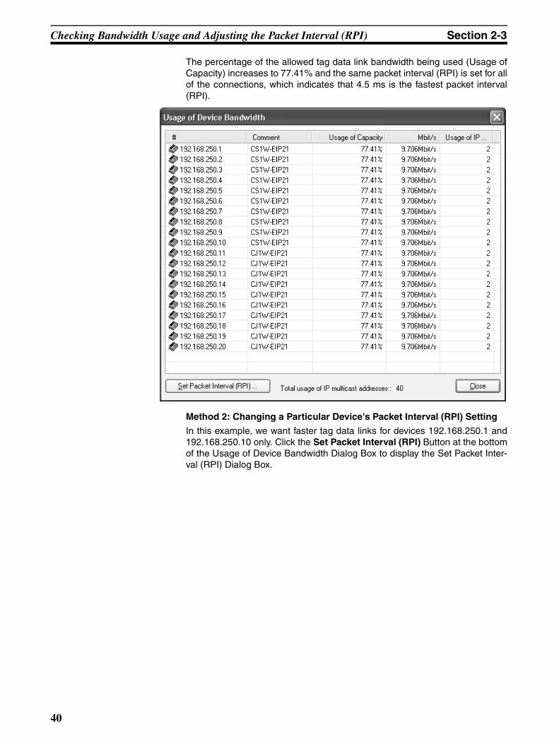
Checking Bandwidth Usage and Adjusting the Packet Interval (RPI) Section 2-3
The percentage of the allowed tag data link bandwidth being used (Usage ofCapacity) increases to 77.41% and the same packet interval (RPI) is set for allof the connections, which indicates that 4.5 ms is the fastest packet interval(RPI).
Method 2: Changing a Particular Device's Packet Interval (RPI) Setting
In this example, we want faster tag data links for devices 192.168.250.1 and192.168.250.10 only. Click the Set Packet Interval (RPI) Button at the bottomof the Usage of Device Bandwidth Dialog Box to display the Set Packet Inter-val (RPI) Dialog Box.
40
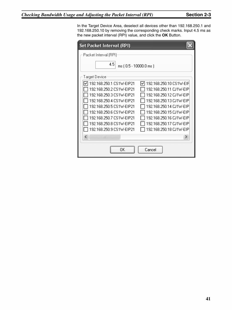
Checking Bandwidth Usage and Adjusting the Packet Interval (RPI) Section 2-3
In the Target Device Area, deselect all devices other than 192.168.250.1 and192.168.250.10 by removing the corresponding check marks. Input 4.5 ms asthe new packet interval (RPI) value, and click the OK Button.
41
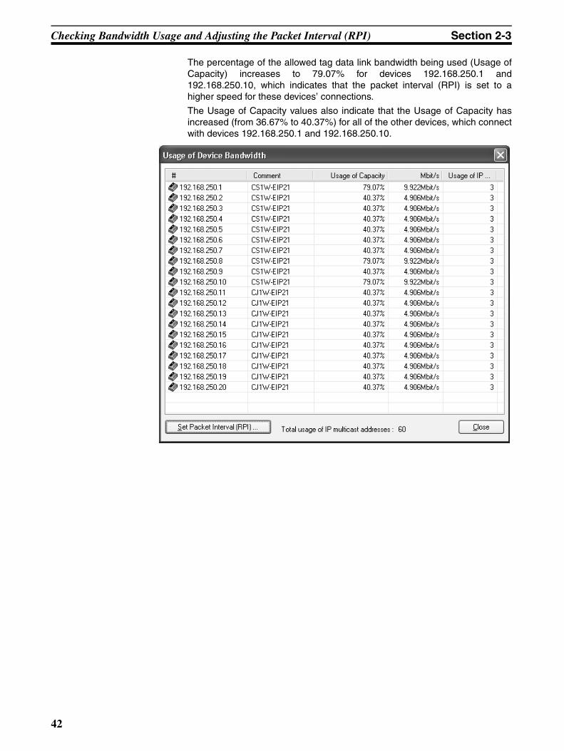
Checking Bandwidth Usage and Adjusting the Packet Interval (RPI) Section 2-3
The percentage of the allowed tag data link bandwidth being used (Usage ofCapacity) increases to 79.07% for devices 192.168.250.1 and192.168.250.10, which indicates that the packet interval (RPI) is set to ahigher speed for these devices’ connections.
The Usage of Capacity values also indicate that the Usage of Capacity hasincreased (from 36.67% to 40.37%) for all of the other devices, which connectwith devices 192.168.250.1 and 192.168.250.10.
42
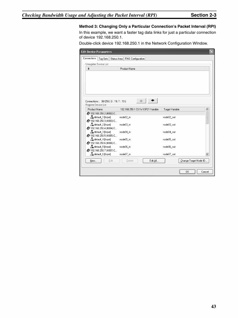
Checking Bandwidth Usage and Adjusting the Packet Interval (RPI) Section 2-3
Method 3: Changing Only a Particular Connection's Packet Interval (RPI)
In this example, we want a faster tag data links for just a particular connectionof device 192.168.250.1.
Double-click device 192.168.250.1 in the Network Configuration WIndow.
43
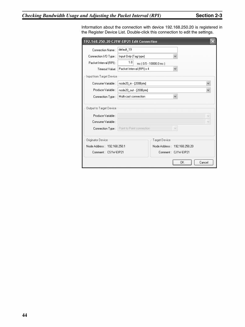
Checking Bandwidth Usage and Adjusting the Packet Interval (RPI) Section 2-3
Information about the connection with device 192.168.250.20 is registered inthe Register Device List. Double-click this connection to edit the settings.
44
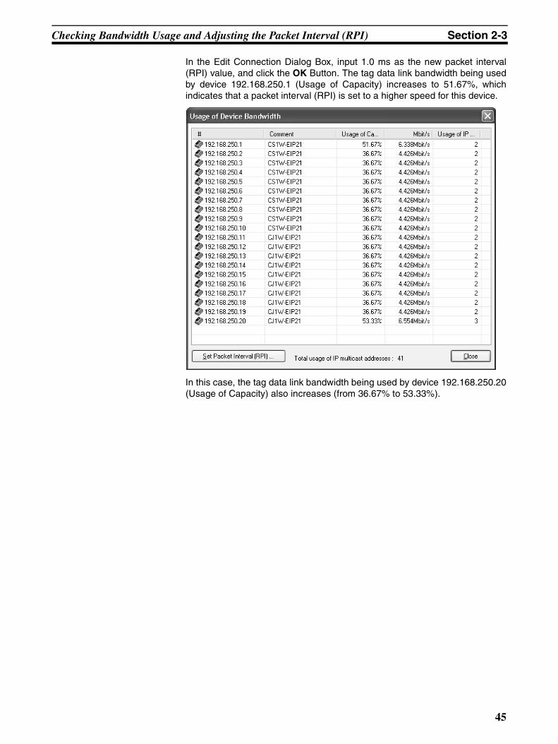
Checking Bandwidth Usage and Adjusting the Packet Interval (RPI) Section 2-3
In the Edit Connection Dialog Box, input 1.0 ms as the new packet interval(RPI) value, and click the OK Button. The tag data link bandwidth being usedby device 192.168.250.1 (Usage of Capacity) increases to 51.67%, whichindicates that a packet interval (RPI) is set to a higher speed for this device.
In this case, the tag data link bandwidth being used by device 192.168.250.20(Usage of Capacity) also increases (from 36.67% to 53.33%).
45

Checking Bandwidth Usage and Adjusting the Packet Interval (RPI) Section 2-3
46

SECTION 3Network Configurator Installation
This section describes Network Configurator installation.
3-1 Network Configurator Installation . . . . . . . . . . . . . . . . . . . . . . . . . . . . . . . . . 48
3-1-1 Installation Preparations . . . . . . . . . . . . . . . . . . . . . . . . . . . . . . . . . . 48
3-1-2 Installing the Network Configurator. . . . . . . . . . . . . . . . . . . . . . . . . 48
3-1-3 Installing the USB Driver (NE1S Series Only) . . . . . . . . . . . . . . . . 50
47
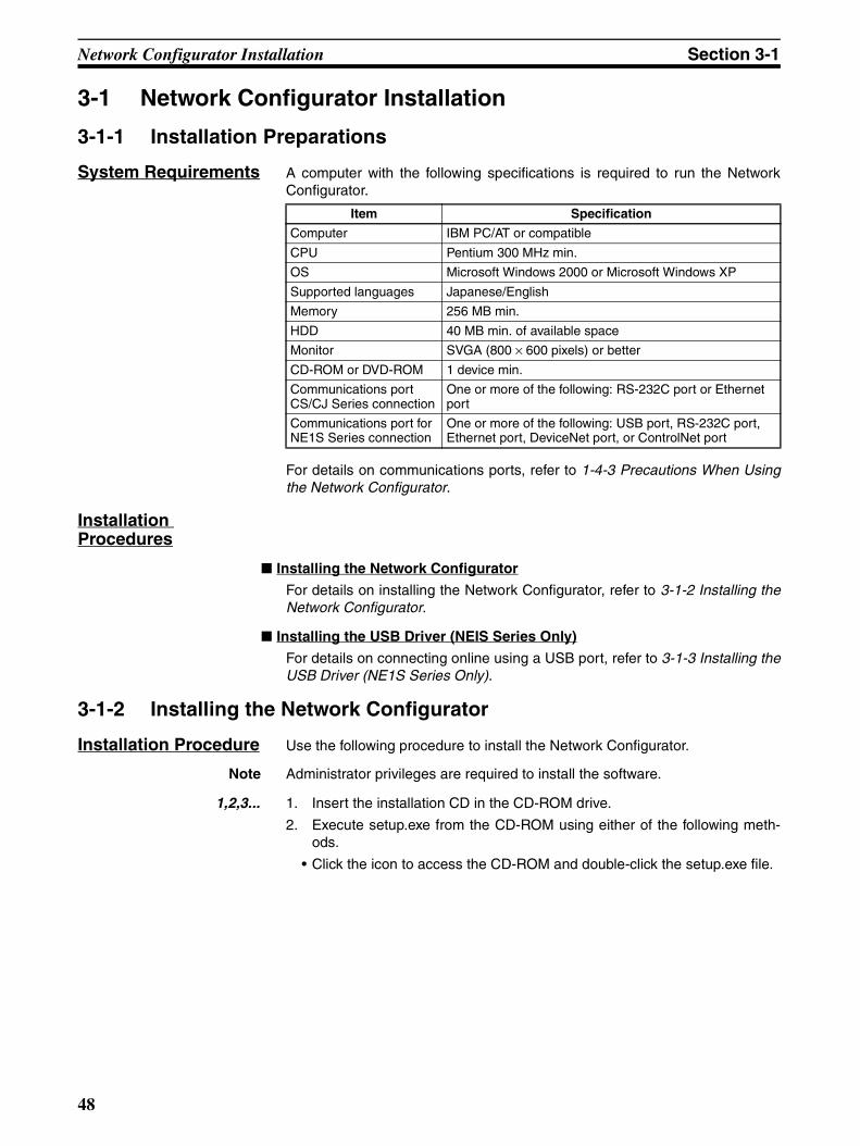
Network Configurator Installation Section 3-1
3-1 Network Configurator Installation
3-1-1 Installation Preparations
System Requirements A computer with the following specifications is required to run the NetworkConfigurator.
For details on communications ports, refer to 1-4-3 Precautions When Usingthe Network Configurator.
Installation Procedures
Installing the Network Configurator
For details on installing the Network Configurator, refer to 3-1-2 Installing theNetwork Configurator.
Installing the USB Driver (NEIS Series Only)
For details on connecting online using a USB port, refer to 3-1-3 Installing theUSB Driver (NE1S Series Only).
3-1-2 Installing the Network Configurator
Installation Procedure Use the following procedure to install the Network Configurator.
Note Administrator privileges are required to install the software.
1,2,3... 1. Insert the installation CD in the CD-ROM drive.
2. Execute setup.exe from the CD-ROM using either of the following meth-ods.
• Click the icon to access the CD-ROM and double-click the setup.exe file.
Item Specification
Computer IBM PC/AT or compatible
CPU Pentium 300 MHz min.
OS Microsoft Windows 2000 or Microsoft Windows XP
Supported languages Japanese/English
Memory 256 MB min.
HDD 40 MB min. of available space
Monitor SVGA (800 × 600 pixels) or better
CD-ROM or DVD-ROM 1 device min.
Communications port CS/CJ Series connection
One or more of the following: RS-232C port or Ethernet port
Communications port for NE1S Series connection
One or more of the following: USB port, RS-232C port, Ethernet port, DeviceNet port, or ControlNet port
48
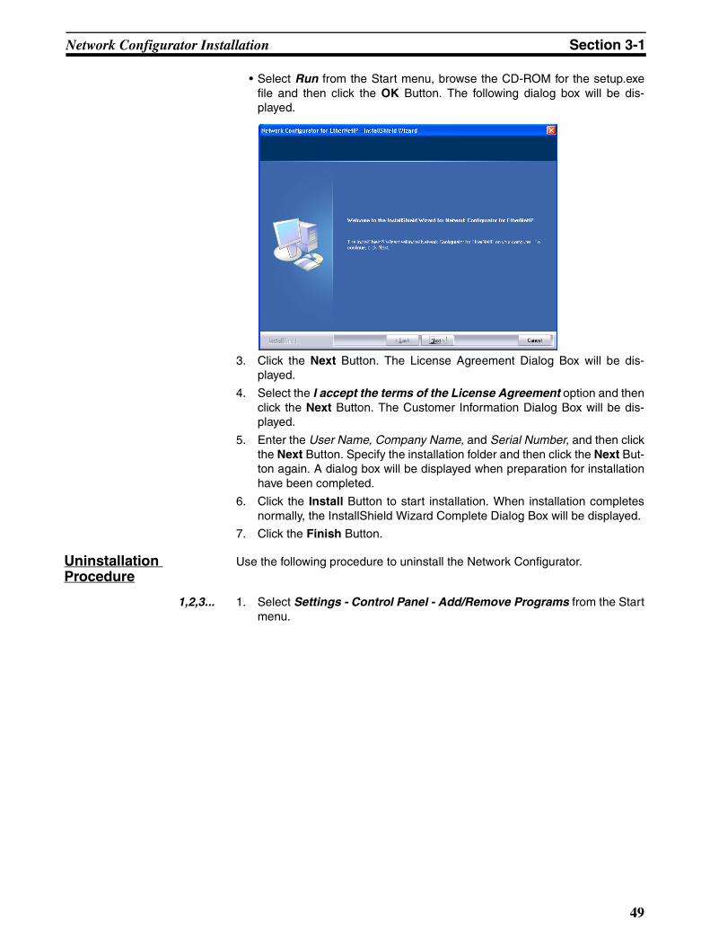
Network Configurator Installation Section 3-1
• Select Run from the Start menu, browse the CD-ROM for the setup.exefile and then click the OK Button. The following dialog box will be dis-played.
3. Click the Next Button. The License Agreement Dialog Box will be dis-played.
4. Select the I accept the terms of the License Agreement option and thenclick the Next Button. The Customer Information Dialog Box will be dis-played.
5. Enter the User Name, Company Name, and Serial Number, and then clickthe Next Button. Specify the installation folder and then click the Next But-ton again. A dialog box will be displayed when preparation for installationhave been completed.
6. Click the Install Button to start installation. When installation completesnormally, the InstallShield Wizard Complete Dialog Box will be displayed.
7. Click the Finish Button.
Uninstallation Procedure
Use the following procedure to uninstall the Network Configurator.
1,2,3... 1. Select Settings - Control Panel - Add/Remove Programs from the Startmenu.
49
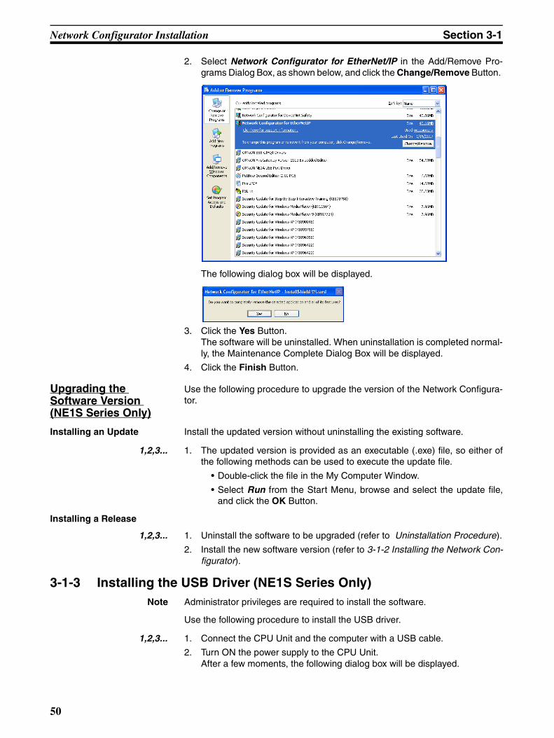
Network Configurator Installation Section 3-1
2. Select Network Configurator for EtherNet/IP in the Add/Remove Pro-grams Dialog Box, as shown below, and click the Change/Remove Button.
The following dialog box will be displayed.
3. Click the Yes Button.The software will be uninstalled. When uninstallation is completed normal-ly, the Maintenance Complete Dialog Box will be displayed.
4. Click the Finish Button.
Upgrading the Software Version (NE1S Series Only)
Use the following procedure to upgrade the version of the Network Configura-tor.
Installing an Update Install the updated version without uninstalling the existing software.
1,2,3... 1. The updated version is provided as an executable (.exe) file, so either ofthe following methods can be used to execute the update file.
• Double-click the file in the My Computer Window.
• Select Run from the Start Menu, browse and select the update file,and click the OK Button.
Installing a Release
1,2,3... 1. Uninstall the software to be upgraded (refer to Uninstallation Procedure).
2. Install the new software version (refer to 3-1-2 Installing the Network Con-figurator).
3-1-3 Installing the USB Driver (NE1S Series Only)Note Administrator privileges are required to install the software.
Use the following procedure to install the USB driver.
1,2,3... 1. Connect the CPU Unit and the computer with a USB cable.
2. Turn ON the power supply to the CPU Unit.After a few moments, the following dialog box will be displayed.
50
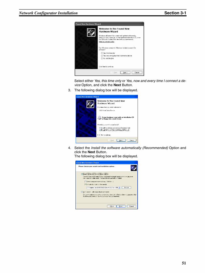
Network Configurator Installation Section 3-1
Select either Yes, this time only or Yes, now and every time I connect a de-vice Option, and click the Next Button.
3. The following dialog box will be displayed.
4. Select the Install the software automatically (Recommended) Option andclick the Next Button.The following dialog box will be displayed.
51
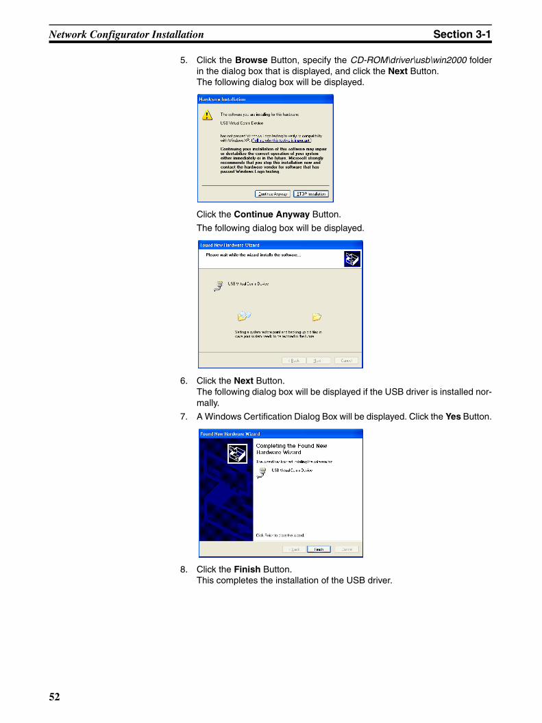
Network Configurator Installation Section 3-1
5. Click the Browse Button, specify the CD-ROM\driver\usb\win2000 folderin the dialog box that is displayed, and click the Next Button.The following dialog box will be displayed.
Click the Continue Anyway Button.
The following dialog box will be displayed.
6. Click the Next Button.The following dialog box will be displayed if the USB driver is installed nor-mally.
7. A Windows Certification Dialog Box will be displayed. Click the Yes Button.
8. Click the Finish Button.This completes the installation of the USB driver.
52

Terms and Conditions of Sale1. Offer; Acceptance. These terms and conditions (these "Terms") are deemed
part of all quotes, agreements, purchase orders, acknowledgments, price lists,catalogs, manuals, brochures and other documents, whether electronic or inwriting, relating to the sale of products or services (collectively, the "Products")by Omron Electronics LLC and its subsidiary companies (“Omron”). Omronobjects to any terms or conditions proposed in Buyer’s purchase order or otherdocuments which are inconsistent with, or in addition to, these Terms.
2. Prices; Payment Terms. All prices stated are current, subject to change with-out notice by Omron. Omron reserves the right to increase or decrease priceson any unshipped portions of outstanding orders. Payments for Products aredue net 30 days unless otherwise stated in the invoice.
3. Discounts. Cash discounts, if any, will apply only on the net amount of invoicessent to Buyer after deducting transportation charges, taxes and duties, and willbe allowed only if (i) the invoice is paid according to Omron’s payment termsand (ii) Buyer has no past due amounts.
4. Interest. Omron, at its option, may charge Buyer 1-1/2% interest per month orthe maximum legal rate, whichever is less, on any balance not paid within thestated terms.
5. Orders. Omron will accept no order less than $200 net billing. 6. Governmental Approvals. Buyer shall be responsible for, and shall bear all
costs involved in, obtaining any government approvals required for the impor-tation or sale of the Products.
7. Taxes. All taxes, duties and other governmental charges (other than generalreal property and income taxes), including any interest or penalties thereon,imposed directly or indirectly on Omron or required to be collected directly orindirectly by Omron for the manufacture, production, sale, delivery, importa-tion, consumption or use of the Products sold hereunder (including customsduties and sales, excise, use, turnover and license taxes) shall be charged toand remitted by Buyer to Omron.
8. Financial. If the financial position of Buyer at any time becomes unsatisfactoryto Omron, Omron reserves the right to stop shipments or require satisfactorysecurity or payment in advance. If Buyer fails to make payment or otherwisecomply with these Terms or any related agreement, Omron may (without liabil-ity and in addition to other remedies) cancel any unshipped portion of Prod-ucts sold hereunder and stop any Products in transit until Buyer pays allamounts, including amounts payable hereunder, whether or not then due,which are owing to it by Buyer. Buyer shall in any event remain liable for allunpaid accounts.
9. Cancellation; Etc. Orders are not subject to rescheduling or cancellationunless Buyer indemnifies Omron against all related costs or expenses.
10. Force Majeure. Omron shall not be liable for any delay or failure in deliveryresulting from causes beyond its control, including earthquakes, fires, floods,strikes or other labor disputes, shortage of labor or materials, accidents tomachinery, acts of sabotage, riots, delay in or lack of transportation or therequirements of any government authority.
11. Shipping; Delivery. Unless otherwise expressly agreed in writing by Omron:a. Shipments shall be by a carrier selected by Omron; Omron will not drop ship
except in “break down” situations.b. Such carrier shall act as the agent of Buyer and delivery to such carrier shall
constitute delivery to Buyer;c. All sales and shipments of Products shall be FOB shipping point (unless oth-
erwise stated in writing by Omron), at which point title and risk of loss shallpass from Omron to Buyer; provided that Omron shall retain a security inter-est in the Products until the full purchase price is paid;
d. Delivery and shipping dates are estimates only; ande. Omron will package Products as it deems proper for protection against nor-
mal handling and extra charges apply to special conditions.12. Claims. Any claim by Buyer against Omron for shortage or damage to the
Products occurring before delivery to the carrier must be presented in writingto Omron within 30 days of receipt of shipment and include the original trans-portation bill signed by the carrier noting that the carrier received the Productsfrom Omron in the condition claimed.
13. Warranties. (a) Exclusive Warranty. Omron’s exclusive warranty is that theProducts will be free from defects in materials and workmanship for a period oftwelve months from the date of sale by Omron (or such other period expressedin writing by Omron). Omron disclaims all other warranties, express or implied.(b) Limitations. OMRON MAKES NO WARRANTY OR REPRESENTATION,EXPRESS OR IMPLIED, ABOUT NON-INFRINGEMENT, MERCHANTABIL-
ITY OR FITNESS FOR A PARTICULAR PURPOSE OF THE PRODUCTS.BUYER ACKNOWLEDGES THAT IT ALONE HAS DETERMINED THAT THEPRODUCTS WILL SUITABLY MEET THE REQUIREMENTS OF THEIRINTENDED USE. Omron further disclaims all warranties and responsibility ofany type for claims or expenses based on infringement by the Products or oth-erwise of any intellectual property right. (c) Buyer Remedy. Omron’s sole obli-gation hereunder shall be, at Omron’s election, to (i) replace (in the formoriginally shipped with Buyer responsible for labor charges for removal orreplacement thereof) the non-complying Product, (ii) repair the non-complyingProduct, or (iii) repay or credit Buyer an amount equal to the purchase price ofthe non-complying Product; provided that in no event shall Omron be responsi-ble for warranty, repair, indemnity or any other claims or expenses regardingthe Products unless Omron’s analysis confirms that the Products were prop-erly handled, stored, installed and maintained and not subject to contamina-tion, abuse, misuse or inappropriate modification. Return of any Products byBuyer must be approved in writing by Omron before shipment. Omron Compa-nies shall not be liable for the suitability or unsuitability or the results from theuse of Products in combination with any electrical or electronic components,circuits, system assemblies or any other materials or substances or environ-ments. Any advice, recommendations or information given orally or in writing,are not to be construed as an amendment or addition to the above warranty.See http://www.omron247.com or contact your Omron representative for pub-lished information.
14. Limitation on Liability; Etc. OMRON COMPANIES SHALL NOT BE LIABLEFOR SPECIAL, INDIRECT, INCIDENTAL, OR CONSEQUENTIAL DAMAGES,LOSS OF PROFITS OR PRODUCTION OR COMMERCIAL LOSS IN ANYWAY CONNECTED WITH THE PRODUCTS, WHETHER SUCH CLAIM ISBASED IN CONTRACT, WARRANTY, NEGLIGENCE OR STRICT LIABILITY.Further, in no event shall liability of Omron Companies exceed the individualprice of the Product on which liability is asserted.
15. Indemnities. Buyer shall indemnify and hold harmless Omron Companies andtheir employees from and against all liabilities, losses, claims, costs andexpenses (including attorney's fees and expenses) related to any claim, inves-tigation, litigation or proceeding (whether or not Omron is a party) which arisesor is alleged to arise from Buyer's acts or omissions under these Terms or inany way with respect to the Products. Without limiting the foregoing, Buyer (atits own expense) shall indemnify and hold harmless Omron and defend or set-tle any action brought against such Companies to the extent based on a claimthat any Product made to Buyer specifications infringed intellectual propertyrights of another party.
16. Property; Confidentiality. Any intellectual property in the Products is the exclu-sive property of Omron Companies and Buyer shall not attempt to duplicate itin any way without the written permission of Omron. Notwithstanding anycharges to Buyer for engineering or tooling, all engineering and tooling shallremain the exclusive property of Omron. All information and materials suppliedby Omron to Buyer relating to the Products are confidential and proprietary,and Buyer shall limit distribution thereof to its trusted employees and strictlyprevent disclosure to any third party.
17. Export Controls. Buyer shall comply with all applicable laws, regulations andlicenses regarding (i) export of products or information; (iii) sale of products to“forbidden” or other proscribed persons; and (ii) disclosure to non-citizens ofregulated technology or information.
18. Miscellaneous. (a) Waiver. No failure or delay by Omron in exercising any rightand no course of dealing between Buyer and Omron shall operate as a waiverof rights by Omron. (b) Assignment. Buyer may not assign its rights hereunderwithout Omron's written consent. (c) Law. These Terms are governed by thelaw of the jurisdiction of the home office of the Omron company from whichBuyer is purchasing the Products (without regard to conflict of law princi-ples). (d) Amendment. These Terms constitute the entire agreement betweenBuyer and Omron relating to the Products, and no provision may be changedor waived unless in writing signed by the parties. (e) Severability. If any provi-sion hereof is rendered ineffective or invalid, such provision shall not invalidateany other provision. (f) Setoff. Buyer shall have no right to set off any amountsagainst the amount owing in respect of this invoice. (g) Definitions. As usedherein, “including” means “including without limitation”; and “Omron Compa-nies” (or similar words) mean Omron Corporation and any direct or indirectsubsidiary or affiliate thereof.
Certain Precautions on Specifications and Use1. Suitability of Use. Omron Companies shall not be responsible for conformity
with any standards, codes or regulations which apply to the combination of theProduct in the Buyer’s application or use of the Product. At Buyer’s request,Omron will provide applicable third party certification documents identifyingratings and limitations of use which apply to the Product. This information byitself is not sufficient for a complete determination of the suitability of the Prod-uct in combination with the end product, machine, system, or other applicationor use. Buyer shall be solely responsible for determining appropriateness ofthe particular Product with respect to Buyer’s application, product or system.Buyer shall take application responsibility in all cases but the following is anon-exhaustive list of applications for which particular attention must be given:(i) Outdoor use, uses involving potential chemical contamination or electricalinterference, or conditions or uses not described in this document.(ii) Use in consumer products or any use in significant quantities. (iii) Energy control systems, combustion systems, railroad systems, aviationsystems, medical equipment, amusement machines, vehicles, safety equip-ment, and installations subject to separate industry or government regulations. (iv) Systems, machines and equipment that could present a risk to life or prop-erty. Please know and observe all prohibitions of use applicable to this Prod-uct. NEVER USE THE PRODUCT FOR AN APPLICATION INVOLVING SERIOUSRISK TO LIFE OR PROPERTY OR IN LARGE QUANTITIES WITHOUTENSURING THAT THE SYSTEM AS A WHOLE HAS BEEN DESIGNED TO
ADDRESS THE RISKS, AND THAT THE OMRON’S PRODUCT IS PROP-ERLY RATED AND INSTALLED FOR THE INTENDED USE WITHIN THEOVERALL EQUIPMENT OR SYSTEM.
2. Programmable Products. Omron Companies shall not be responsible for theuser’s programming of a programmable Product, or any consequence thereof.
3. Performance Data. Data presented in Omron Company websites, catalogsand other materials is provided as a guide for the user in determining suitabil-ity and does not constitute a warranty. It may represent the result of Omron’stest conditions, and the user must correlate it to actual application require-ments. Actual performance is subject to the Omron’s Warranty and Limitationsof Liability.
4. Change in Specifications. Product specifications and accessories may bechanged at any time based on improvements and other reasons. It is our prac-tice to change part numbers when published ratings or features are changed,or when significant construction changes are made. However, some specifica-tions of the Product may be changed without any notice. When in doubt, spe-cial part numbers may be assigned to fix or establish key specifications foryour application. Please consult with your Omron’s representative at any timeto confirm actual specifications of purchased Product.
5. Errors and Omissions. Information presented by Omron Companies has beenchecked and is believed to be accurate; however, no responsibility is assumedfor clerical, typographical or proofreading errors or omissions.

Specifications subject to change without notice.Printed in the U.S.A.
OMRON ELECTRONICS LLC
1 Commerce DriveSchaumburg, IL 60173 847.843.7900 For US technical support or other inquiries: 800.556.6766
OMRON CANADA, INC. 885 Milner AvenueToronto, Ontario M1B 5V8416.286.6465
OMRON ON-LINEGlobal - www.omron.comUSA - www.omron247.comCanada - www.omron.caBrazil - www.omron.com.brLatin America - www.espanol.omron.com
Z909-E1-01 ©2007 OMRON ELECTRONICS LLC
UNITED STATESTo locate a Regional Sales Office, local Distributor orto obtain product information, call: 847.843.7900
MEXICO SALES OFFICES
Mexico, D.F. 555.660.3144Ciudad Juárez 656.623.7083Monterrey, N.L 818.377.4281Querétaro 442.135.4510
BRAZIL SALES OFFICESao Paulo 55.11.2101.6310
ARGENTINA SALES OFFICECono Sur 54.114.787.1129
OTHER LATIN AMERICAN SALES [email protected]