operation manual … please observe the following 1 1.1 emphasized sections warning! refers to...
TRANSCRIPT

GLOBAL AVAILABILITY
GLOBAL SERVICE
WORLDWIDEEQUIPMENTO P E R A T I O N M A N U A L
AdvancingSlide
97118/97119

1
2
3 5
6
109
8
7
4
Insidefront
covercrops
3/4”shorterat this
hairlinerule

R
97110
Change
Off
On
PowerRefill
Empty
97109
R
97107
R
97105
R
97110
Change
Off
On
PowerRefill
Empty
97110
R
97108
R
97106
97115
R
97102
CONT
bar psi
97102
R
0,5
1
1,51,6
5
10
15
20
23
psibar
10
20
4060 80
100
120
140
psibar
2
4
6
8
97101
97113/14.Titel Raster
9711397114
97115
97118 97119
97113/14.Titel Raster
9711397114
9711897119
9711397114
97116
97111 97112
97101
1x
1x1x
2x
R
97103
ESC
AB
AB
B A
97103 + 97204
R
ESC
AB
AB
B A
R
97103
ESC
AB
AB
B A
97006
ONT
R
R
STARTCONT
bar psi
97006
Reservoir Options
Manual Controller Semi-AutomaticController
Hand-heldApplicator
Dispense Valve
Rotospray
Advancing Slide
Rotospray
Dispense Valve
Automatic Controller
Syringe System
Reservoir Options
Advancing Slide

Contents
1 Please observe the following Page No.1.1 Emphasized Sections 11.2 Items Supplied 11.3 For Your Safety 21.4 Usage 2
2 Description2.1 Operating Elements and Connections 22.2 Theory of Operation 3
3 Technical Data 3
4 Installation4.1 Environmental Conditions 54.2 Connecting the Unit 54.3 Assembling the Unit 54.4 Setting Up of the Unit 6
4.4.1 Adjusting the Slide Movements 64.4.2 Adjusting the Wetting Position 74.4.3 Controlling the Mechanical Sequence 7
5 Dispensing5.1 First Operation 8
5.1.1 Controlling the Dispensing Sequence 85.2 Shutdown 85.3 Returning to Operation 8
6 Care and Maintenance 8
7 Troubleshooting 9
8 Documentation8.1 Pin Assignment of the Plugs 108.2 Assignment of the Pneumatic Connection, coaxial 108.3 Accessories and Spare Parts 11
9 Warranty 12

1
Please observe the following1
1.1 Emphasized Sections
Warning!
Refers to safety regulations and requires safety measures that protect the operator or otherpersons from injury or danger to life.
Caution!
Emphasizes what must be done or avoided so that the unit or other property is not damaged.
Notice
☞ Gives recommendations for better handling of the unit during operation or adjustment as well as forservice activities.
The numbers printed in bold in the text refer to the corresponding position numbers in the illustration onthe front fold-out page (see Section 2.1).
● The point emphasizes an instruction step.Instruction steps in the illustrations are indicatedwith arrows.When several instruction steps are indicated inan illustration, the shading of the arrow has thefollowing meaning:Black arrow = 1st stepGrey arrow = 2nd stepWhite arrow = 3rd step
1.2 Items Supplied
1 Advancing Slide 97118, 50 mm, or Advancing Slide 97119, 100 mm;
1 Connection Kit;1 Instruction Manual 97118 / 97119.
☞ As a result of technical development, the illustrations and descriptions in this instruction manual candeviate in detail from the actual unit delivered.

2
Please observe the following1
1.3 For Your Safety
For safe and successful operation of the unit, read these instructions completely.
If the instructions are not observed, the manufacturer can assume no responsibility.
Danger of pinching!● Do not reach into the area of the forward and backward movement of the attachment flange 4.
1.4 Usage
With the the Advancing Slide 97118 or 97119, a stationary applicator or a rotorspray with stationaryapplicator can be moved exactly and vibration-free to a defined dispensing position and returned to itsinitial position.
The simultaneous control of these units requires the use of a LOCTITE Controller 97103 with a SolenoidValve Module 97204.
2.1 Operating Elements and Connections
☞ ● Fold out the illustration inside the front cover!
1 Cylinder
2 Electrical proximity switch, rear end position (initial position)
3 Electrical proximity switch, forward end position (wetting position)
4 Attachment flange
5 Mounting bracket (for stationary applicator or rotorspray)
6 Angle for the attachment of the mounting bracket 5
7 Air outlet choke for inner hose I (forward advancement)
8 Pneumatic hose
9 Air outlet choke for outer hose 0 (backward advancement)
10 Pneumatic connection co-axial
☞ ● Please pay attention that the ends of the tubes of the co-axial air hose are cut in a straight and cleanway. Otherwise the dispensing equipment can not function at all or only defectively.
Description2
3
Description2
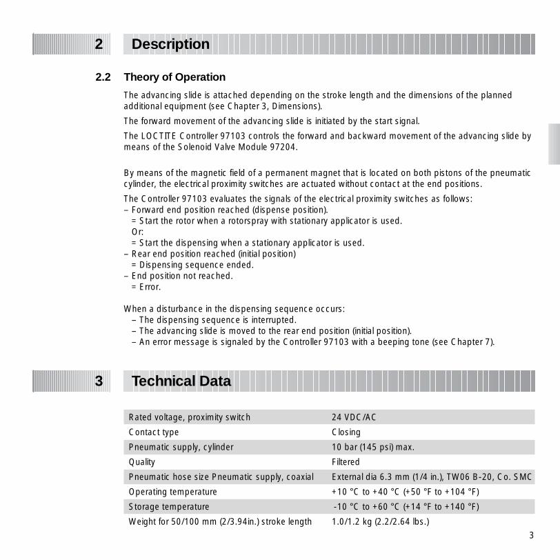
2.2 Theory of Operation
The advancing slide is attached depending on the stroke length and the dimensions of the plannedadditional equipment (see Chapter 3, Dimensions).
The forward movement of the advancing slide is initiated by the start signal.
The LOCTITE Controller 97103 controls the forward and backward movement of the advancing slide bymeans of the Solenoid Valve Module 97204.
By means of the magnetic field of a permanent magnet that is located on both pistons of the pneumaticcylinder, the electrical proximity switches are actuated without contact at the end positions.
The Controller 97103 evaluates the signals of the electrical proximity switches as follows:– Forward end position reached (dispense position).
= Start the rotor when a rotorspray with stationary applicator is used.Or:= Start the dispensing when a stationary applicator is used.
– Rear end position reached (initial position)= Dispensing sequence ended.
– End position not reached.= Error.
When a disturbance in the dispensing sequence occurs:– The dispensing sequence is interrupted.– The advancing slide is moved to the rear end position (initial position).– An error message is signaled by the Controller 97103 with a beeping tone (see Chapter 7).
Rated voltage, proximity switch 24 VDC/AC
Contact type Closing
Pneumatic supply, cylinder 10 bar (145 psi) max.
Quality Filtered
Pneumatic hose size Pneumatic supply, coaxial External dia 6.3 mm (1/4 in.), TW06 B-20, Co. SMC
Operating temperature +10 °C to +40 °C (+50 °F to +104 °F)
Storage temperature -10 °C to +60 °C (+14 °F to +140 °F)
Weight for 50/100 mm (2/3.94in.) stroke length 1.0/1.2 kg (2.2/2.64 lbs.)
Technical Data3

4
Technical Data3
Dimensions
55 m
m/2
.16
in.
84 m
m/3
.31
in.
154.5 mm/6.08 in.
150 mm/5.9 in.
4 mm/ .16 in.
98.6 + 50 mm (+ 100 mm)/ 3.88 + 1.97 in. (+ 3.94 in.)
82 mm/ 3.23 in.
30/ 1.18
128.6 + 50 mm (+ 100 mm)/ 5.06 + 1.97 in. (+3.94 in.)
130 mm/5.12 in.129 mm/5.08 in.
72 m
m/2
.83
in.
20/ .79
DIN74-Km5
DIN74-Km5
Adjustment range

5
Installation4
4.1 Environmental Conditions
– Non-condensing humidity– No splash water
4.2 Connecting the Unit
☞ It is easier to keep track of the dispensing sequence when the connection units that are combinedtogether are connected to the same dispensing channel.
4.3 Assembling the Unit
☞ The advancing slide should be installed in a flat and horizontal way. So an exact positioning of thedispensing needle can be guaranteed.
● Attach the cylinder of the advancing slide depending on the desired wetting position.
● Attach a rotorspray with the mounting bracket 5on the angle 6.Mount the stationary applicator according to theoperating instructions of the rotorspray.
Or as an alternative:
● Attach a stationary applicator with the mountingbracket 5 on the angle 6.
max. 2 m/ 6.6 ft.
A
B
85–264 VAC/50–440 Hz
2 AM
XS1: Start XS2: Reservoir XS3: Turntable XS4: DC Motor XS5: Monitor A XS6: Monitor B XS7: RS232 Master XS8: RS232 Slave XS9: PLC Interface XS10: I/O port XS11: Servo A/B XS12: Channel A/B
Loctite (Ireland) Ltd.
Made in Germany cat.no.97103
XS1
XS2
XS3
XS4
XS5
XS12
XS11
XS10
XS9
XS6
XS7
XS8
0

6
Installation4
4.4 Setting Up of the Unit
☞ The following adjustment steps should be performed with a completely assembled dispensing unit,e.g., a slide with mounted rotorspray and stationary applicator.Only in this manner can the space requirements be correctly evaluated.
● In the main directory PERIPHERY SETUP on the Controller 97103, check whether all of the necessaryconnection units are activated (see operating instructions for the Controller 97103).
4.4.1 Adjusting the Slide Movements
These adjustment steps should not be performed on a part.● Check that no obstacles are located in the stroke area to avoid damage to the advancing slide
or other equipment.
Danger of pinching!● Do not reach into the area of the forward and backward movement of the attachment flange 4.
● Loosen the knurled locking nuts on the air outletchokes 7 and 9.
● Turn the knurled screws of the air outlet chokes7 and 9 counter clockwise to the stop and thenscrew them approx. halfway in again.
● In the directory MANUAL OPERATION, switch the advancing slide on and off (see operatinginstructions for the Controller 97103). Adjust the knurled screws of the air outlet chokes 7 and 9 so that:– The forward and backward movements are performed smoothly.– Each end position is reached in a vibration-free manner.

7
4.4.2 Adjusting the Wetting Position
● Remove the workpiece to be wetted.
● Move the dispensing unit to the forward end position (advance forward).
● Mount the workpiece.
☞ Adjust the advancement with rotorspray and/or stationary applicator so that the rotor disc and/or thedispensing needle is exactly at the wetting position.
● Retighten all loosened fasteners.
● Return the dispensing unit to the rear end position (advance backward).
4.4.3 Controlling the Mechanical Sequence
● Check that no obstacles are located in the stroke area to avoid damage to the advancing slideor other equipment.
● In the directory MANUAL OPERATION, initiate the start of a dispensing sequence (see operatinginstructions for the Controller 97103).
● Check whether the dispensing unit is correctly positioned and if the end positions are reached.
☞ The proximity switches are set at the factory so that the forward end position (wetting position) andthe rear end position (initial position) are correctly interrogated. If a proximity switch is incorrectlyadjusted, an error message occurs in normal dispensing operation (see Chapter 7). In the directory MANUAL OPERATION, however, no error message occurs. The reaching of an endposition can be recognized only by the lighting of the LED of the corresponding proximity switch.
Adjusting of a Proximity Switch:
● Loosen the socket head screw and slide theproximity switch 3 forwards or backwards in thegroove.
● Tighten the socket head screw in the desiredposition.
Tightening torque: 0.2 Nm max.
Installation4
max. 0.2 Nm

8
5.1 First Operation
5.1.1 Controlling the Dispensing Sequence
● Purge the stationary applicator of air according to the operating instructions for the stationaryapplicator.
☞ Remove the stationary applicator from the holder for purging.
● Perform the filling of the feedline according to the operating instructions of the LOCTITE Controller97103.
● Before remounting the stationary applicator, adjust the piston stroke (suck-back effect) and the airoutlet chokes (see operating instructions for the Stationary Applicator).
● In the directory MANUAL OPERATION, initiate the start of a dispensing sequence (see operatinginstructions for the Controller 97103).
☞ The advancing slide is automatically switched on by a start signal from the Controller 97103.
Rotorspray with Stationary Applicator Mounted:The rotorspray is switched on when the forward end position is reached (wetting position).The dispensing takes place automatically after the rotor reaches its rated speed in accordance with thepreselected dispensing time.
Stationary Applicator Mounted:The dispensing takes place automatically after reaching the forward end position (wetting position) inaccordance with the preselected dispensing time.After the dispensing time has elapsed, the slide returns to the rear end position (initial position).
5.2 Shutdown
☞ The advancing slide is switched off automatically at the end of the dispensing time by the Controller97103.
5.3 Returning to Operation
☞ The advancing slide is automatically switched on by a start signal from the Controller 97103.
Dispensing5
Care and Maintenance6
The unit requires no special care and maintenance.
9
Cylinder
DownNOK
Cylinder Up
NOK
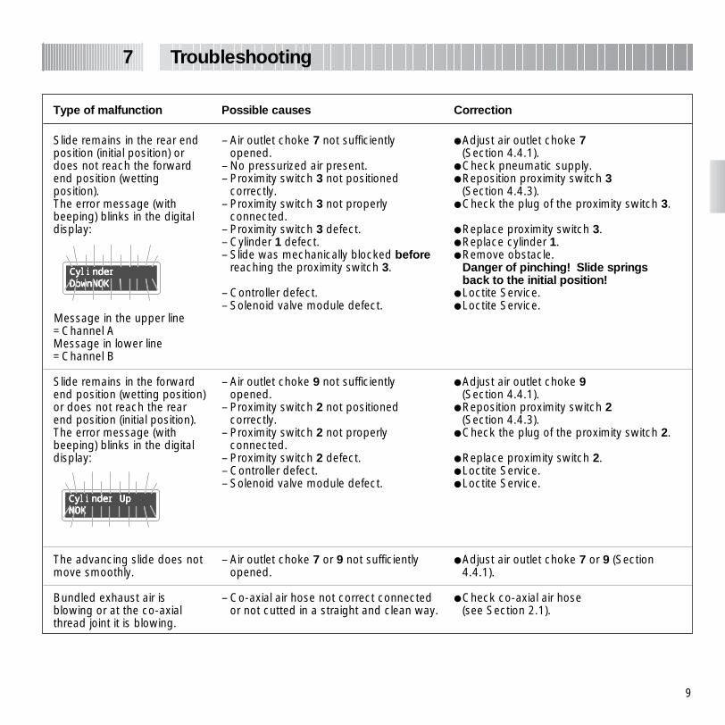
Type of malfunction Possible causes Correction
– Air outlet choke 7 not sufficientlyopened.
– No pressurized air present.– Proximity switch 3 not positioned
correctly.– Proximity switch 3 not properly
connected.– Proximity switch 3 defect.– Cylinder 1 defect.– Slide was mechanically blocked before
reaching the proximity switch 3.
– Controller defect.– Solenoid valve module defect.
– Air outlet choke 9 not sufficientlyopened.
– Proximity switch 2 not positionedcorrectly.
– Proximity switch 2 not properlyconnected.
– Proximity switch 2 defect.– Controller defect.– Solenoid valve module defect.
– Air outlet choke 7 or 9 not sufficientlyopened.
– Co-axial air hose not correct connectedor not cutted in a straight and clean way.
● Adjust air outlet choke 7(Section 4.4.1).
● Check pneumatic supply.● Reposition proximity switch 3
(Section 4.4.3).● Check the plug of the proximity switch 3.
● Replace proximity switch 3.● Replace cylinder 1.● Remove obstacle.
Danger of pinching! Slide springsback to the initial position!
● Loctite Service.● Loctite Service.
● Adjust air outlet choke 9(Section 4.4.1).
● Reposition proximity switch 2(Section 4.4.3).
● Check the plug of the proximity switch 2.
● Replace proximity switch 2.● Loctite Service.● Loctite Service.
● Adjust air outlet choke 7 or 9 (Section4.4.1).
● Check co-axial air hose (see Section 2.1).
Slide remains in the rear endposition (initial position) ordoes not reach the forwardend position (wettingposition).The error message (withbeeping) blinks in the digitaldisplay:
Message in the upper line =Channel AMessage in lower line=Channel B
Slide remains in the forwardend position (wetting position)or does not reach the rearend position (initial position).The error message (withbeeping) blinks in the digitaldisplay:
The advancing slide does notmove smoothly.
Bundled exhaust air isblowing or at the co-axialthread joint it is blowing.
Troubleshooting7

10
Documentation8
8.1 Pin Assignment of the Plugs
Electrical Proximity Switch
1
NS
-IN
DU
K 2
3
4
+ 24 VDC
GND
A / IN
V +
V -
Reedswitch (optional)
1
2
1
S1
2
3
4
+ 24 VDC
A
8.2 Assignment of the Pneumatic Connection, coaxial
Outer hose O Backward advancement (Initial position)
Inner hose I Forward advancement (Wetting position)
Electricalproximity switch
FestoSME-8-K-LED-24150 855
Lumberg 4pol. Stecker
RSC 4 / 73x 0.14 qmmlength: 2 m (6.6 ft.)type: shield, flexiapproved: VDE, CA, UL
Reedswitch
FestoSME-8-K-LED-220152 820
Lumberg 4pol. Stecker
RSC 4 / 72x 0.25 qmmlength: 2 m (6.6 ft.)type: shield, flexiapproved: VDE, CA, UL

11
Documentation8
Pos. No. Description Loctite Order No.
1 Connection Kit Advancing Slide(2 electr. proximity switches, 2 m pneum. hose, coaxial, Ext. dia. 6,3mm).....97261
2 Pneumatic Connector, coaxial, with Air Outlet Choke, SMC AS 1100W
3 Air Outlet Choke, Festo
4 Electrical Proximity Switch, Festo SME-8-K-LED-24
5 Reedswitch, Festo SME-8-K-LED-220
6 Cylinder 100 mm, Festo DPZ-20-100-P-ACylinder 50 mm, Festo DPZ-20-50-P-A
8.3 Accessories and Spare Parts

12
Warranty9
Loctite expressly warrants that all products referred to in this Instruction Manual under Advancing Slide97118/97119 (hereafter called “Products”) shall be free from defects in materials and workmanship. Loctite’s liabilityshall be limited, at its option, to replacing those Products which are shown to be defective either in materials orworkmanship or to credit to the purchaser the amount of the purchase price thereof (plus freight and insurancecharges paid therefore by the user). The purchaser’s sole and exclusive remedy for breach of warranty shall be suchreplacement or credit.
A claim of defect in materials or workmanship in any Products shall be allowed only when it is submitted to Loctitein writing within one month after discovery of the defect or after the time the defect should reasonably have beendiscovered and in any event, within 12 months after the delivery of the Products to the purchaser. No such claim shall beallowed in respect of Products which have been neglected or improperly stored, transported, handled, installed,connected, operated, used or maintained or in the event of unauthorized modification of the Products including, whereproducts, parts or attachments for use in connection with the Products are available from Loctite, the use of products,parts or attachments which are not manufactured by Loctite.
No Products shall be returned to Loctite for any reason without Loctite’s prior written approval. Products shall be returnedfreight prepaid, in accordance with Loctite’s instructions.
NO WARRANTY IS EXTENDED TO ANY EQUIPMENT WHICH HAS BEEN ALTERED, MISUSED, NEGLECTED, ORDAMAGED BY ACCIDENT, OR IF THE SYSTEM IS USED TO DISPENSE ANY LIQUID MATERIAL OTHER THAN LOCTITECORPORATION PRODUCTS.
EXCEPT FOR THE EXPRESS WARRANTY CONTAINED IN THIS SECTION, LOCTITE MAKES NO WARRANTY OF ANYKIND WHATSOEVER, EXPRESS OR IMPLIED, WITH RESPECT TO THE PRODUCTS.
ALL WARRANTIES OF MERCHANTABILITY, FITNESS FOR A PARTICULAR PURPOSE, AND OTHER WARRANTIES OFWHATEVER KIND (INCLUDING AGAINST PATENT OR TRADEMARK INFRINGEMENT) ARE HEREBY DISCLAIMED BYLOCTITE AND WAIVED BY THE PURCHASER.
THIS SECTION SETS FORTH EXCLUSIVELY ALL OF LOCTITE’S LIABILITY TO THE PURCHASER IN CONTRACT, INTORT OR OTHERWISE IN THE EVENT OF DEFECTIVE PRODUCTS.
WITHOUT LIMITATION OF THE FOREGOING, TO THE FULLEST EXTENT POSSIBLE UNDER APPLICABLE LAWS,LOCTITE EXPRESSLY DISCLAIMS ANY LIABILITY WHATSOEVER FOR ANY DAMAGES INCURRED DIRECTLY ORINDIRECTLY IN CONNECTION WITH THE SALE OR USE OF, OR OTHERWISE IN CONNECTION WITH, THEPRODUCTS, INCLUDING, WITHOUT LIMITATION, LOSS OF PROFITS AND SPECIAL, INDIRECT OR CONSEQUENTIALDAMAGES, WHETHER CAUSED BY LOCTITE’S NEGLIGENCE OR OTHERWISE.

-Declarations of Conformity
Manufacturer
declares that machine contained in this delivery is the machine designated below, is however incomplete and that itsoperation is prohibited until it can be determined that the machine is in accordance with the provisions of EC machineregulations.
Designation of the unit Advancing Slide
Unit number 97118/97119
Applicable EC Regulations EG-Machine Regulations 89/392/EWG, version 93/68/EWG
Applicable harmonized standards DIN EN 292 Part 1 11.1991; DIN EN 292 Part 2 11.1991
Date / Manufacturer’s signature 1995
Information regarding the Signer President – Worldwide Manufacturing (Peter G. Dowling)
For changes to the unit that were not approved by Loctite, this declaration loses its validity.

Loctite is a registered trademark of Loctite Corporation, Hartford, CT USA. © 1995 P/N8950094 – 12/95