operation manual - rinnai · rinnai 4 commercial controller om to isolate and maintain the pump(s):...
TRANSCRIPT

Rinnai 1
This Controller shall be installed in accordance with:• Manufacturer’s Installation Instructions• Current AS/NZS 3000 • Local Regulations and Municipal Building Codes including local OH&S requirementsThis appliance must be installed, maintained and removed only by an Authorised Person.For continued safety of this controller it must be installed and maintained in accordance with the manufacturers instructions.
Models DDSTAT | DDSOLAR | DDCPDEL
Operation ManualRinnai Commercial Controller
Part
No.
154
0111
7

Rinnai 2 Commercial Controller OM
READ ALL INSTRUCTIONS BEFORE USING THIS COMMERCIAL CONTROLLER
Always comply with the following precautions to avoid dangerous situations and to ensure optimum performance.
Failure to carefully read and follow all instructions in this manual can result in equipment malfunction, property damage, personal injury and/or death.
WARNINGS: WHEN IGNORED, CAN RESULT IN SERIOUS INJURY OR DEATH.
CAUTIONS: WHEN IGNORED, CAN RESULT IN MINOR INJURY OR PRODUCT DAMAGE.
WARNING
REGULATORY / INSTALLATION
This controller shall be installed in accordance with:
• Manufacturer’s Installation Instructions.
• Current AS/NZS 3000.
• Local Regulations and Municipal Building Codes including local OH&S requirements.
This controller must be installed, maintained and removed by an Authorised Person.
For continued safety of this controller must be installed and maintained in accordance with the manufacturers instructions.
Take care when opening or unpacking this controller. Failure to do so may result in serious injury or product failure.
DO NOT modify the electrical wiring of this controller. If the wiring is damaged or deteriorated then it must be replaced by an Authorized Person. Failure to do so may result in electric shock, fire, serious injury or product failure.
CONTROLLER INSTALLATION POSITIONING
• When installing and locating the Controller (other than the default factory position), please ensure that the position is dry and free from constant exposure to water droplets, both GPO should be in use, if not the unused GPO should be plugged.
• Do not use power boards with this Controller.
WARNING & REGULATORY

Rinnai 3 Commercial Controller OM
DDSTAT
The DDSTAT model is used in conjunction with Demand Duo systems and operates by measuring the temperature of the water in the storage tank. If the temperature of the water falls below the “tank set temperature” and the “tank low limit temperature” the controller will switch ON the pump(s) and circulate water from the tank through the HD water heater(s) and back to the tank. The DDSTAT is configured with a power feed to the controller, a tank temperature probe, 2 integrated GPOs for pump or HD power supplies, and a second temperature probe that can be utilised to detect hot water return temperatures from the HD heat source(s) if required.
• Available “TANK SET TEMPERATURE” range is 60°C to 82°C (factory default setting 65°C)
• Available “TANK LOW LIMIT TEMPERATURE” range is: 3°C less “tank set temperature” to 50°C (factory default setting 5°C).
For example:
Tank Set Temperature Tank Low Limit Temperature Range Available
82°C 50°C to 79°C
71°C 50°C to 68°C
60°C 50°C to 57°C
The DDSTAT Controller can be set up with the following pump operation:
System Description Model Name LH GPO RH GPODD with 1 HD & 1 Pump DD 1 Permanently active for HD Pump
DD with 2 or more HDs & 1 Pump DD 2 + (1 Pump system) Disabled PumpDD with 2 or more HDs & 2 Pumps DD 2 + (2 Pump system) Pump 1 Pump 2
NOTEFor DD systems with 2 pumps either simultaneous or alternation operation mode can be requested.
DDSTAT BASIC OPERATION
Once the controller has power, the tank temperature (home) screen is displayed. If the temperature probe is in place a temperature reading will be displayed, if no probe is attached then an error will be registered and displayed.To program the “Tank Set Temperature”:
1. From home screen select "SET" button 1.
1 2 3
4SET INFO MAINT
TANK TEMPERATURE 4
PUMP AUTO
2. Using the arrow buttons select the "TANK SET TEMPERATURE" then select "ACCEPT" button 2.
1 2 3
4ACCEPT
TANK SETTEMPERATURE
65
3. Using the arrow buttons select the "TANK LOW LIMIT TEMPERATURE" then select "ACCEPT" button 2.
1 2 3
4ACCEPT
TANK LOW LIMITTEMPERATURE
60
DDSTAT OPERATION

Rinnai 4 Commercial Controller OM
To isolate and maintain the pump(s):
4. From the home screen select "MAINT" button 3.
1 2 3
4SET INFO MAINT
TANK TEMPERATURE 4
PUMP AUTO
5. Select "PUMP" button 2.
1 2 3
4EXIT PUMP TEMP
MAINTENANCE MODESELECT FUNCTION
6. Use the arrow buttons to manually operate the pump on and off, select "ACCEPT" button 2 to run command.
1 2 3
4ACCEPT
PUMPOFF
7. If a second pump has been configured you have the option to manually operate this pump also.
1 2 3
4ACCEPT
PUMP 2OFF
To view system temperatures:
1. From home screen select "MAINT" button 3.
1 2 3
4SET INFO MAINT
TANK TEMPERATURE 4
PUMP AUTO
2. Select "TEMP" button 3 system temperatures will then be displayed.
1 2 3
4EXIT PUMP TEMP
MAINTENANCE MODESET FUNCTION
3. Tank temperature will be shown.
1 2 3
4EXIT MODEL
TEMPERATURESTANK: 4
4. If the 2nd temperature sensor has been enabled a return temperature from the HD heat source will be shown.
1 2 3
4EXIT MODEL
TEMPERATURESTANK: 4
RETURN: 7
DDSTAT OPERATION

Rinnai 5 Commercial Controller OM
To view controller configuration:
1. For controller configuration information, from home screen select "MAINT", Select '"TEMP" button 3.
1 2 3
4EXIT PUMP TEMP
MAINTENANCE MODESET FUNCTION
2. From the Temperature screen select "MODEL" button 2.
1 2 3
4EXIT MODEL
TEMPERATURESTANK: 4
RETURN: 7
3. The Controller configuration will then be displayed select "EXIT" button 2 to return to home screen.
1 2 3
4EXIT
CURRENT MODEL ISDD5-6, VA0.3
2 PUMP, IT, CM, ID1
To view pump status and run times:
1. From the home screen select "INFO" button 2.
1 2 3
4SET INFO MAINT
TANK TEMPERATURE 4
PUMP AUTO
2. If one pump has been configured the pump operation status and run time hours will be displayed.
1 2 3
4OK
PUMP ONTOTAL RUN HOURS
0
3. If two pumps have been configured the screen will scroll through pump operation status and run time hours.
1 2 3
4OK
PUMP 1: ONPUMP 2: ON
1 2 3
4OK
PUMP RUN HOURSPUMP 1: 0PUMP 2: 0
DDSTAT ERROR DETECTIONThe DDSTAT controller has in-built system error detection connected to voltage free contacts. Errors that are present are displayed on the home operating screen.The voltage free contacts can connect to BMS and be either programmed to open or close on error detection. With the 2nd sensor connected and enabled, the controller has the ability to detect three predetermined errors, see below:
• Error 1, Tank Temperature falls below low set point and does not rise to temperature set point within the prescribed period of time. This generally indicates a faulty pump.
• Error 2, With the 2nd sensor enabled only. The temperature of the water returning from the HD Water Heaters is insufficient. This generally indicates a faulty heat source
• Error 3, If any one or both of the sensors are faulty (outside of measurement range).
DDSTAT OPERATION
Rinnai 6 Commercial Controller OM
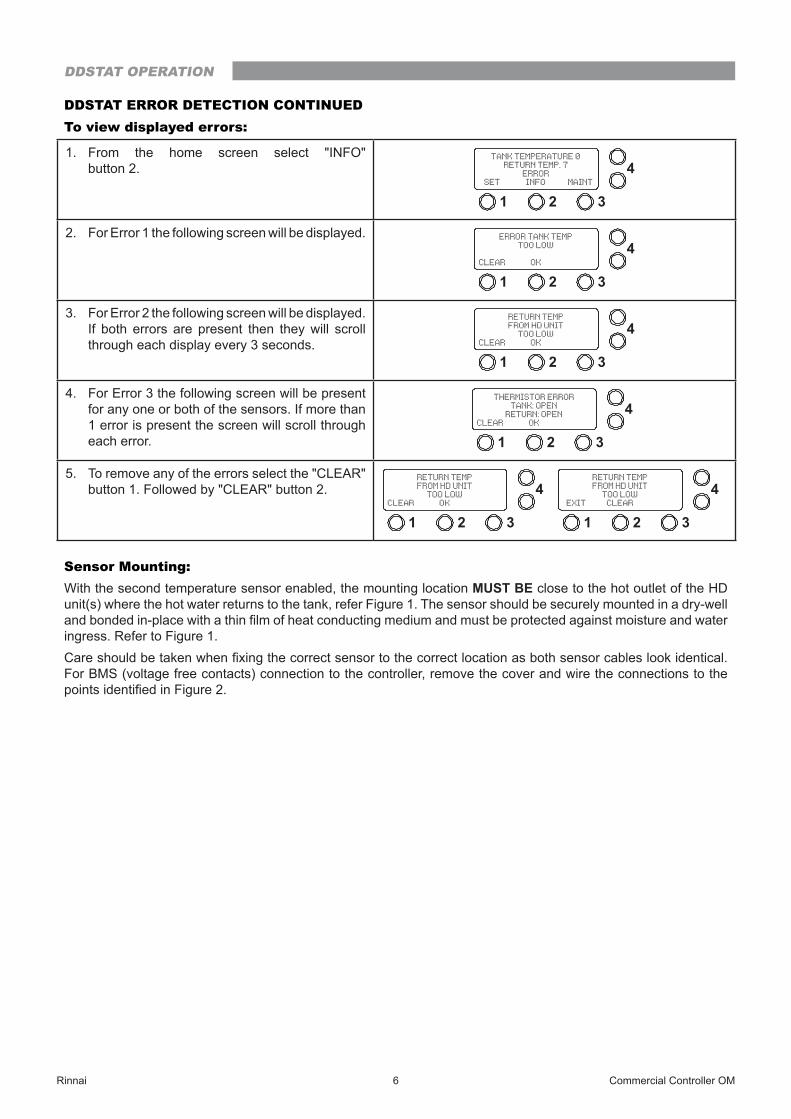
DDSTAT ERROR DETECTION CONTINUEDTo view displayed errors:
1. From the home screen select "INFO" button 2.
1 2 3
4SET INFO MAINT
TANK TEMPERATURE 0RETURN TEMP. 7
ERROR
2. For Error 1 the following screen will be displayed.
1 2 3
4CLEAR OK
ERROR TANK TEMPTOO LOW
3. For Error 2 the following screen will be displayed. If both errors are present then they will scroll through each display every 3 seconds.
1 2 3
4CLEAR OK
RETURN TEMPFROM HD UNIT
TOO LOW
4. For Error 3 the following screen will be present for any one or both of the sensors. If more than 1 error is present the screen will scroll through each error. 1 2 3
4CLEAR OK
THERMISTOR ERRORTANK: OPEN
RETURN: OPEN
5. To remove any of the errors select the "CLEAR" button 1. Followed by "CLEAR" button 2.
1 2 3
4CLEAR OK
RETURN TEMPFROM HD UNIT
TOO LOW
1 2 3
4EXIT CLEAR
RETURN TEMPFROM HD UNIT
TOO LOW
Sensor Mounting:With the second temperature sensor enabled, the mounting location MUST BE close to the hot outlet of the HD unit(s) where the hot water returns to the tank, refer Figure 1. The sensor should be securely mounted in a dry-well and bonded in-place with a thin film of heat conducting medium and must be protected against moisture and water ingress. Refer to Figure 1.Care should be taken when fixing the correct sensor to the correct location as both sensor cables look identical. For BMS (voltage free contacts) connection to the controller, remove the cover and wire the connections to the points identified in Figure 2.
DDSTAT OPERATION

Rinnai 7 Commercial Controller OM
2ndOptionalSensor
Plug withdry well
Brass Tee
Water Flow Tank SensorLocation
Closed end copper pipewelded to return pipe
2nd Optional Sensor
Insulation
ReturnPipe
Return Pipe
2nd OptionalSensor preferred
fixing method
Alternative 2nd OptionalSensor fixing method
Return Pipe
Fig. 1 Approximate Sensor Locations
(VOLTAGE FREE CONTACTS)
Fig. 2 DDSTAT Internal PCB showing Thermistor Connections
DDSTAT OPERATION

Rinnai 8 Commercial Controller OM
DDSOLAR (COMMERCIAL SOLAR CONTROLLER)The solar controller's function is to turn the solar pump on and off to collect and transfer solar heated water to the storage water cylinder. It can be supplied to operate single or dual pumps with the further option to have dual pumps switched simultaneously or alternatively (12 hour cycle).
NOTEFor single pump systems the pump must be plugged into the right hand GPO.
The controller determines if there is capacity in the cylinder(s) to store more solar heated water and when the temperature difference between the cylinder(s) and collector(s) is suitable for energy collection the controller will activate the circulating pump(s).
Solar gain pump 'ON'
1 2 3
4INFO MAINT
TANK TEMPERATURE 17COLLECTOR TEMP. 37
PUMP COLLECTING
No Solar gain pump idle.
1 2 3
4INFO MAINT
TANK TEMPERATURE 34COLLECTOR TEMP. 30
PUMP IDLE
When there is a differential temperature between the solar collector (hot sensor) and the tank (cold sensor) the circulating pump is switched on. When differential falls to below the predetermined limit the circulation pump is then switched off.When the tank temperature sensor reaches the predetermined set point the pump is de-energised. This prevents water that is too hot returning from the solar collectors to the storage cylinder and activating the P&TR valve.Alternatively if the collector temperature is over the safe operating temperature the controller de-energises the pump.The other function of the controller is to circulate water through the collectors when there are low ambient temperature frost conditions to prevent the collector from freezing. When the hot temperature sensor (in collector) drops below the pre-determined limit the pump activates to prevent freezing. The circulator will stop once the hot sensor temperature increases. This is a function that is selected from the Maintenance menu. This function MUST be enabled, in areas that may experience low temperatures and to comply with warranty conditions.To view pump status and run times:
1. From the home screen select "INFO" button 2.
1 2 3
4INFO MAINT
TANK TEMPERATURE 11COLLECTOR TEMP. 26
PUMP COLLECTING
2. The screen will alternate between pump operation status and run time hours.
1 2 3
4OK
PUMP 1: ONPUMP 2: OFF
1 2 3
4OK
PUMP RUN HOURSPUMP 1: 0PUMP 2: 0
Activating Frost Protection:
1. From home screen select "MAINT" button 3.
1 2 3
4INFO MAINT
TANK TEMPERATURE 34COLLECTOR TEMP. 30
PUMP IDLE
2. From the Maintenance screen select “PUMP” button 2.
1 2 3
4EXIT PUMP TEMP
MAINTENANCE MODESELECT FUNCTION
DDSOLAR OPERATION

Rinnai 9 Commercial Controller OM
Activating Frost Protection Continued:
3. From the Pump screen select "ACCEPT" button 2.
1 2 3
4ACCEPT
PUMP OFF
4. Using the arrow buttons select either "YES" or "NO" for Frost Mode then select "ACCEPT" button 2. This will take you back to the Maintenance screen. 1 2 3
4ACCEPT
USE FROST MODEIN AUTO?
YES
DDSOLAR ERROR DETECTIONThe DDSolar controller has in-built system error detection connected to voltage free contacts. During solar gain if there is no temperature rise within 2 hours then an error will be displayed, errors that are present are displayed on the main operating screen. See the two errors listed below.
1. No temperature rise within a predetermined time during a solar gain period.
1 2 3
4OK
ERROR NO SOLARTEMPERATURE RISE
PUMP DISABLED
2. If one or both thermistors are outside the predetermined measurement range. This screen justifies an error with the collector short.
1 2 3
4CLEAR OK
THERMISTOR ERRORTANK: OK
COLLECTOR SHORT
The voltage free contacts can connect to BMS and either programmed as open or closed on error detection.Refer to Figure 3 for BMS connection and thermistor locations.
(VOLTAGE FREE CONTACTS)
(Collector Temp)
Fig. 3 DDSOLAR Internal PCB showing Thermistor Connections
DDSOLAR OPERATION

Rinnai 10 Commercial Controller OM
DDPCDEL (DELUXE PUMP CONTROLLER)The DDPCDEL is used to monitor commercial flow and return systems. The main functionality of the controller in this mode is to extend the life of the pumps by regular alternation or overcome any issues with faulty pump if present.The features of this controller are:
• Operating temperature selection range of 40°C to 80°C with 1°C increment setting.
• 12 hour changeover cycle between pumps (this is the factory Pre-set but 24 hours is available on request).
• Capability of controlling dual pump systems up to a power load of 900 Watts per pump.
• Numerical display of monitored water temperature.
• Thermistor temperature sensor (to be located on pipework common to both pumps).
• Voltage free contacts selectable as open or closed on fault for easy connection to BMS. On initial start up the controller will run in "AUTO" mode, energise pump one and display the current temperature reading from the thermistor. It can also be factory configured to run 2 pumps simultaneously.
1. Home Screen image.
1 2 3
4SET INFO MAINT
RING MAINTEMPERATURE: 11
PUMP AUTO
TO PROGRAM THE "RING-MAIN TEMPERATURE"
1. From home screen select "SET" button 1.
1 2 3
4SET INFO MAINT
RING MAINTEMPERATURE: 34
PUMP AUTO
2. Using the arrow buttons select the "RING-MAIN TEMPERATURE" then select 'ACCEPT" button 2.
1 2 3
4ACCEPT
SET RING MAINTEMPERATURE
65
Once the controller has been configured to suit the application it will begin to monitor the Ring-Main temperature and adjust accordingly. If the temperature reaches the set point all pumps will be de-energised, thus saving energy, if the temperature reduces, within the set range, a single pump will be energised. This single pump will remain energised to maintain this temperature for the set period of time (12 hours) when in "AUTO" mode. When the time period has elapsed the controller will automatically switch to the second pump and continue to maintain the temperature.If you press the "INFO" button the pump run hours and active pumps are displayed.
When Ring-Main temperature reaches the set point all pumps will be de-energised, the active pump is identified as the next to operate.
1 2 3
4OK
PUMP 1: OFFPUMP 2: OFF
PUMP 1 IS ACTIVE
When Ring-Main temperature within 5°C less of set point, one pump is operational.
1 2 3
4OK
PUMP 1: ONPUMP 2: OFF
When the Ring-Main temperature is between 5°C to 10°C less the set temperature both pumps energised.
1 2 3
4OK
PUMP 1: ONPUMP 2: ON
When operating in "AUTO" mode and the Ring-Main temperature drops below the set point for a prescribed period of time then an error is displayed and the controller automatically switches to the alternative pump.
DDPCDEL OPERATION

Rinnai 11 Commercial Controller OM
Main temperature 5°C low error screen image.
1 2 3
4SET INFO MAINT
RING MAINTEMPERATURE
ERROR
Pump 1 disabled screen.
1 2 3
4OK
ERROR MAIN TEMP5 deg. LOW
PUMP 1: DISABLED
(VOLTAGE FREE CONTACTS)
Ringmain Temp
Fig. 4 DDPCDEL Internal PCB showing Thermistor Connections
If the temperature returns to the set point, within a prescribed period of time, the controller will stop alternating to the affected pump and continue to display a pump error.If the Ring-Main temperature drops below the set point for a prescribed period of time while both pumps are operating simultaneously then the low temp error is displayed however both pumps continue to operate. If the temperature recovers, within a prescribed time frame, then the error is removed and the controller returns to normal operation. If the temperature continues to drop in excess of 10°C below the set point and does not recover for a prescribed period of time the controller will disable both pumps.
Main temperature 10°C low error screen image.
1 2 3
4CLEAR OK
ERROR MAIN TEMP10 deg. LOW
PUMPS DISABLED
The controller has an additional inbuilt function to identify a thermistor error.
Thermistor open circuit. Thermistor values are outside the prescribed range,
1 2 3
4CLEAR OK
THERMISTOR ERRORRING OPEN
As a final setup prior to operating the flow and return pump system, ensure all pipework with the flow and return system is full of water and all air has been purged.This can be done using the air vent screw that good quality pumps are supplied with, see example right.
DDPCDEL OPERATION

Part No. 15401117 12 Commercial Controller OM Issue 2 - 13/08/18
CONTACTS
Rinnai has a Service and Spare Parts network with personnel who are fully trained and equipped to give the best service on
your Rinnai appliance. If your appliance requires service, please call our National Help Line. Rinnai recommends that this
appliance be serviced at least every 1 year.With our policy of continuous improvement, we reserve the right to change, or discontinue at any time, specifications or
designs without notice.
Australia Pty. Ltd.ABN 74 005 138 769
100 Atlantic DriveKeysborough, Victoria 3173
P.O. Box 460Braeside, Victoria 3195
AU45204
Product Sales & Service National Help Line
Tel: 1300 555 545* Fax: 1300 555 655 *Monday to Friday, 8.00am to 5.30pm EST
For further information visit www.rinnai.com.auor email [email protected]