operation manual - utility solutions, inc
TRANSCRIPT

USGT-600 GROUNDS TESTER
Phone (828)323-8914Fax (828)323-8410Email [email protected] www.utilitysolutionsinc.com
101 33rd Street Drive SE · Hickory, NC 28602
Operation ManualC-00835 USGT-600 Rev. 2.2 (3-5-15)

2
USGT-600 ACCESSORY ADAPTERSUtility Solutions offers the following optional adapters
for use with the USGT-600 Grounds Tester:
PART NUMBER DESCRIPTIONUSGT-600-15KVBUSHING USGT-600 15 kV Loadbreak Bushing AdapterUSGT-600-15KVELBOW USGT-600 15 kV Loadbreak Elbow AdapterUSGT-600-27KVBUSHING USGT-600 27 kV Loadbreak Bushing AdapterUSGT-600-27KVELBOW USGT-600 27 kV Loadbreak Elbow AdapterUSGT-600-SUB USGT-600 3½” OD Substation Clamp Adapter
Lineman driven. Field proven.
UTILITYSOLUTIONS
™
Phone (828)323-8914Fax (828)323-8410Email [email protected] www.utilitysolutionsinc.com
101 33rd Street Drive SE · Hickory, NC 28602
27 Kv ELBOWUSGT-600-27KVELBOW
27 Kv BUSHINGUSGT-600-27KVBUSHING
15 Kv ELBOWUSGT-600-15KVELBOW
15 Kv BUSHINGUSGT-600-15KVBUSHING
SUBSTATION CLAMP ADAPTOR
NOTE: All adapters are CNC machined out of solid brass stock.
CALL your local Utility Solutions, Inc. representative, or contact us:828-323-8914 [email protected]

3
USGT High Current Test Source Specifications
Electrical Input Voltage 120V AC Nominal Input Current 15 A AC Max Output Current 0 – 600A AC Output Compliance 2.5V AC Duty Cycle 50% 15 min on; 15 min off Meters Ammeter .5% accuracy Voltmeter .5% Accuracy Safety Features Thermal Overload Protection AC Input Circuit Breaker Dimensions Weight 44 lbs Dimensions 20 x 15 x 8 Optional Accessories Elbow Adapter Straight Stud Parking Stand Adapter Direct Source Cables

4
USGT-600 High Current Test Source with REACHTM
The USGT-600 is a safe, new and unique high AC current source product for testing personal protective grounds, molded case circuit breakers, and mechanical jumpers. Using the patent pending REACHTM technology, the current carrying cable impedance to the device under test can be effectively eliminated allowing testing of substation ground mats, low impedance ground points and other products or places where the driving cable impedances need to be eliminated from the actual measurement. The USGT-600 provides a high current output combined with a low output voltage for maximum operator safety. The unit is also thermally protected from overload and provides a visual indication if overload does occur. In most instances, simply reducing the output current to zero and allowing the unit to cool and return to normal mode as indicated by the overload light is all that is required. The Resistance Extended Analog Check (REACHTM) technology allows the operator to test individual components in personal grounding assemblies, sub-station grounding mats and any device requiring an extended length cable by using the supplied voltmeter extension cable assembly. Source driving cable impedances are removed from the measurement allowing only that portion under test to be accurately determined. The 600 A AC output current provides the highest output current in a standard model device. Safety First Grounding jumper assemblies can be damaged by rough handling, long term use, weathering, UV exposure, and corrosion and/or oxidation. This deterioration may be physical and/or electrical in nature and the working condition of grounding jumper assemblies can only be determined by a combination of both visual inspection and electrical testing. The test procedures outlined in Appendix A provide a means of determining if a grounding jumper assembly meets the minimum electrical requirements. To ensure electrical worker safety, grounding jumper assemblies should be tested at regular intervals throughout their operational lifetime. Inspection should always be preceded by a through knowledge of system ground fault current capabilities, company policies, standards, and work practices. Finally, the high current test source is capable of producing currents that will quickly heat high resistance points or defective areas of cable, clamps, and ferrules. These will become hot and could cause burns. The equipment operator should wear proper hand protection when testing any assembly or product.

5
A fault carrying ASTM grade chart for conductors and clamps is included for convenience [See Chart 1]. Individual components of any protective ground assembly should have the same or greater grade rating and should be verified during inspection. The assembly grade rating is the rating of the lowest grade component in the assembly (the weakest link). For instance, if the cable is rated to grade 5 and the clamp is rated to grade 2, then the complete grounding assembly can at best be rated to only grade 2. Visual Inspection of Grounding Assemblies Personal Grounding assemblies should first be inspected for kinks, pinches, flat areas, or nicks in the cable, corrosion of the cable conductor or clamp and the like. If the cable has a clear insulating jacket, the cable should be free of corrosion and breaking of the individual stranding as this reduces the circular cross section of the conductor and the ability of the cable to carry the fault current for the specific time as outlined by ASTM F855-03. The cable should also be inspected at the interface point to any ferrule, clamp, or stress point for broken strands of cable. Broken stranding in cable can give an ohmic resistance reading that “passes” a micro-ohm resistance check, but will not withstand the required fault current or current carrying ampacity. The most accurate and “true” test is to pass a nominal test current for the wire size thru the cable and check that no cable, ferrule, or clamp heating occurs. OSHA places two performance requirements on grounding equipment that can not be satisfied by visual inspection alone. Per OSHA 29 CFR 1910.269(n) Protective grounding equipment shall be capable of conducting the maximum fault current that could flow at the point of grounding for the time necessary to clear the fault. Protective grounds shall have an impedance low enough to cause immediate operation of protective devices in case of accidental energizing. Testing Personal Grounds If the cable assembly to be tested has passed a thorough visual inspection, personal protective grounds should then be electrically tested by attaching each end of the cable assembly via clamp or adapter to the current output posts, rotating the test current control knob until the corresponding cable AWG size test current is reached and observing the voltage meter indicator. If the voltage indication is below the specified reading for the length cable, the cable is good. If the voltage indication is above the specified reading for the length cable, the cable may be defective. Please refer to the section on inspection and trouble shooting in Appendix A for additional details for determining grounding assembly viability.

6
High Current Test Source Operation 1. Make sure the test unit is turned off and the current output control is rotated
fully counterclockwise (the min position). 2. Install the test connectors in the threaded isothermal terminal blocks on the
front or side panel. Use the supplied tightening tool to fully tighten the test connectors (slide the tool through the hole in the shaft).
3. Place the voltage switch into the “normal” position. 4. Plug the female end power cord into the male 3 pin euro style power
connector on the front panel. 5. Plug the power cord plug into a standard wall 110V AC outlet rated at least
10 amps. 6. Determine the proper test current then connect the jumper, source cables or
ground assembly to the test connectors. Refer to Appendix E for Cable Schematic. If testing a jumper or ground jumper assembly, measure to the nearest 1/2 foot prior to attaching to test connectors.
7. Turn the power switch to the “ON” position and observe that the panel meters indicate zero.
8. Slowly rotate the output current control clockwise and observe the ammeter for the proper test current setting for the class/grade or wire size (Appendix B).
9. Record the voltage reading on the voltmeter. 10. Rotate the output current control fully counterclockwise to the “MIN” position
before shutting the device off. Follow the test procedure instructions for determining the Pass or Fail condition of the jumpers or ground assemblies.
Troubleshooting Failed Personal Grounds using REACHTM technology Troubleshooting “failed” grounds may be accomplished by plugging the supplied red and black auxiliary leads into their corresponding colored banana jacks and placing the voltage switch to the REACHTM position. The voltmeter test has been “extended” to allow individual components to be measured. By placing one test lead on the isothermal block and the other on the clamp, the voltage drop across the clamp may be measured. By placing the leads on each ferrule, the voltage drop of the cable may be determined. This resistance reading capability allows the operator to measure the various voltage drops of specific connections of the assembly to aid in repair / trouble shooting of the assembly. Please refer to Appendix C for the nominal voltage drop levels for AWG cable size, test current, and clamp data. The charts are referenced by the cable sizes and range from #2 thru 350 Kcmil sizes.

7
Additionally, breaker contact and any low impedance point can be measured using the auxiliary leads. This method allows the actual voltage drop of the component to be measured while eliminating the voltage drop of the current supply cables giving a “true” voltage drop reading. Testing Mechanical Jumpers Most mechanical jumpers are only high voltage tested for the KV rating they are specified. The high voltage test is only a portion of the test, as high voltage testing only tests the cable for dielectric strength and not rated current capacity. High voltage testing places a nominal high voltage, but extremely low current on the cable for dielectric testing. A more through test will also test the cable at rated current, but at a very low voltage for safety. The procedure is much the same for the mechanical jumper as the ground jumper. If the cable assembly to be tested has passed a through visual inspection, mechanical jumpers should then be electrically tested by attaching each end of the cable assembly via clamp or adapter to the current output posts, rotating the test current control knob until the corresponding cable size AWG test current is reached (Appendix B) and observing the voltage meter indicator. If the voltage indication is below the specified reading for the AWG and cable length, the cable is good. If the voltage indication is above the specified reading for the length cable, the cable may be defective. Please refer to the section on inspection and trouble shooting in Appendix A for additional details for determining mechanical jumper assembly viability. Testing Substation Grounding Mats using REACHTM technology Testing substation grounding mats can be easily accomplished using the REACHTM technology and a pair of high current cable assemblies (optionally supplied). Connect cables to each side of the ground mat to test. Place the voltage rocker switch to the REACHTM position. Connect the black and red banana leads. These are the voltmeter extension jumper leads to allow the REACHTM test technology to eliminate the sourcing cable impedance from the test. Only the ground mat resistance will be tested at this point. Rotate the current control clockwise until the ammeter reads nominal test current. If there is no reading on the ammeter, re-check the connections to the mat. If there is no reading on the voltmeter, make sure the leads are connected to the terminating point of the current carrying cables. The resistance of the ground mat may be found by the following formula: Voltage Drop V, (in volts) = Current I, (in amps) * Resistance R, (in ohms) or,
R = V / I

8
For example, take the voltage drop reading and divide by the current reading on the ammeter to determine the ground mat resistance. This resistance value will allow determination of the ground mat effectiveness. One tip is to set the output current at a number easy to use in calculations i.e., 100A, 200A, or 500A. The actual Amp setting will depend on the average AWG of the mat conductor. Refer to your company standards and practices for allowed resistance values. Testing up to 600 Amp Molded Case Circuit Breakers Molded case circuit breakers with ratings up to 600 A trip currents may also be tested using the high current source. Connect the circuit breaker to the output terminals via the optionally supplied cable extender leads and slowly rotate the current control while watching the ammeter indication. The circuit breaker should trip open and current indication should go to zero at the current level indicated by the name tag current rating of the circuit breaker. Depending on the type of breaker, the current indication at the trip point should be within approximately 10% of the nametag rating. If a higher or lower current reading is observed or the breaker fails to trip, consult the manufacturer’s data sheet or specification for further information. Testing Certain Time-over-Current Relays Up to 600A time-over-current relays may also be tested using the high current capabilities of the unit. Additionally, a stop watch will be required for this test. To start, connect the optionally supplied output leads to the over-current relay under test. Make sure all current elements are connected per the manufacturer’s data sheet. Rotate the current control knob until the ammeter indicates about 10% of the relay trip rating. Continue rotating the current control just until the relay indicates “tripped” condition. Leave the current control knob in that position. Turn the power to the high current source off. Reset the relay or allow the over current relay to cool down as specified on the relay data sheet. To test the timing function after initial setup, start the stop watch and power the high current test source on simultaneously. Stop the stopwatch when the relay indicates tripped. Consult the relay data sheet for the proper current curve and note that the current as indicated on the high current source and the time fall on one the over-current timing curves as specified by the relay manufacturer. Higher current tests, up to 600 A may be performed for a 1.5 X trip, 2 x trip, etc. for determining proper relay function.

9
Appendix A: Inspection and Testing of Grounding Jumper Assemblies The suggested sequence of inspection and testing of Grounding Jumper Assemblies is as follows: Auditing and Preliminary Inspection A method for maintaining a log and serial number is recommended. After the assembly is logged in and verified as a valid product and prior to electrical testing, grounding jumper assemblies shall be visually and manually inspected for: grease, grime, dirt, discoloration of jacket material, oxidation of clamp to ferrule interface, oxidation of cable at ferrule interface point, cracked or broken ferrules and clamps, exposed or broken strands, cut, mashed, kinked or flattened cable, cable jacket damage (cut, cracked, swollen or soft spots) or any other obvious conditions that would adversely affect the jumper performance. If any of these conditions are found, the grounding jumper assembly shall be rejected or repaired in accordance with the company corrective maintenance and/or repair section listed below. If the assembly passes the visual check, proceed to the electrical test section. Disassembly and Cleaning Disassemble the grounding jumper assembly and thoroughly clean all current carrying interfaces with isopropyl alcohol and a stiff wire brush. While some grounding jumper assemblies may pass the electrical test without disassembly and cleaning, the goal is to return the assembly to the field in “like new” condition. Remember, that the lower the resistance the lower the voltage and current across the worker. Reassembly Reassemble grounding jumper assembly. All physical connections should be checked for tightness with torque values as specified by the manufacturer. Recommended torque values for the clamps are: 1. Jam nut for threaded ferrules, 20 ft/lb 2. Jam nut for pin ferrules, 28 ft/lb
10
Identify Cable Gauge and Grounding Jumper Length Positively identify cable gauge and measure grounding jumper to the nearest foot. For lengths not shown in the table, round the measured length up to the nearest length shown in the table. The pass/fail criterion is based on the total impedance value of the assembly, which is typically higher than the established impedance values for new assemblies. This increase in impedance is due the expected normal deterioration of the assembly caused by aging, contamination and oxidation - particularly in the contact areas of the cable ferrules and clamps. The slight increase in impedance is such as to permit the grounding jumper assembly to perform safely when subjected to the ASTM withstand fault current values as listed in ASTM 855-97 (see chart attached). Grounding jumper assemblies shall be tested in accordance with the operation instructions furnished with the test device, making sure that the cable is laid out per the manufacture’s recommendations. Corrective Maintenance and/or Repair Grounding jumper assemblies which fail the electrical test may require additional maintenance and/or repairs including but not limited to, additional cleaning of current carrying interfaces, tightening of physical connections, replacement of cable, clamps and/or ferrules. Grounding jumper assemblies that fail the electrical test after additional maintenance or repairs are performed, shall be removed from service and permanently marked, tagged or destroyed to prevent reuse. Locating the high resistance area(s) is facilitated by the heating of these areas due to circulation of rated continuous current through the cable under test. If there are no apparent hot spots on the clamp or ferrule, the high resistance may be further localized by using the patent pending REACHTM technology. Individual components may thus be tested according to the method outlined. Record Keeping and Marking It is recommended that tested grounding jumper assemblies be marked with date of test and test results be entered into a record keeping system. Along with an individual serial number, length, and next test date; a complete history can be established on a “birth to death” basis for the assembly. This methodology works well for single ground assemblies as well as cluster assemblies with multiple arms. A sample chart is supplied in Appendix D.

11
In Service Care Grounding jumper assemblies that have been tested on a scheduled basis and returned to the field still require inspection and maintenance in the field. A visual inspection prior to each use of all current carrying portions of clamps should be made. If necessary, wire brush any oxidation built up on these surfaces. This includes the ferrule to clamp connection and current carrying portion of the clamp jaw. If a clamp with serrated jaw inserts is used, the insert should be removed and wire brushed on both sides and reinstalled. Remember that in a de-energized maintenance work procedure the grounding jumper assembly is the only personal protective equipment available to the electrical workers and that the safety of each worker is totally dependent on the condition of the protective equipment used. Insulated Bypass Jumpers Flexible insulated bypass jumpers are devices use to bridge electrical circuits for short periods of time at work locations when conductors or equipment may be opened or electrically disconnected during normal work operations. These insulated bypass jumpers carry both an electrical rating (dielectric strength of jacket, KV) and a continuous current rating. While a dielectric test will confirm the electrical high voltage integrity of the jacket; it will not confirm the current carrying integrity, ampacity, since the dielectric test only circulates a very small current through the cable. Typically this test involves applying only milliamps of current, but thousands of volts to test jacket dielectric properties. The high current test source will confirm the current carrying capability of the insulated bypass jumper by virtue of circulating rated continuous current (up to hundreds of amps) through the cable. Simply follow the directions for testing grounding jumper assemblies and note the volt drop on the pass/fail chart of the test set. The recommended sequence of testing insulated bypass jumpers would be the same sequence as those for grounding jumper assembles as above. The complete test will also have the high voltage dielectric withstand test as yet another component of the complete test to ensure the integrity of the jumper.
12
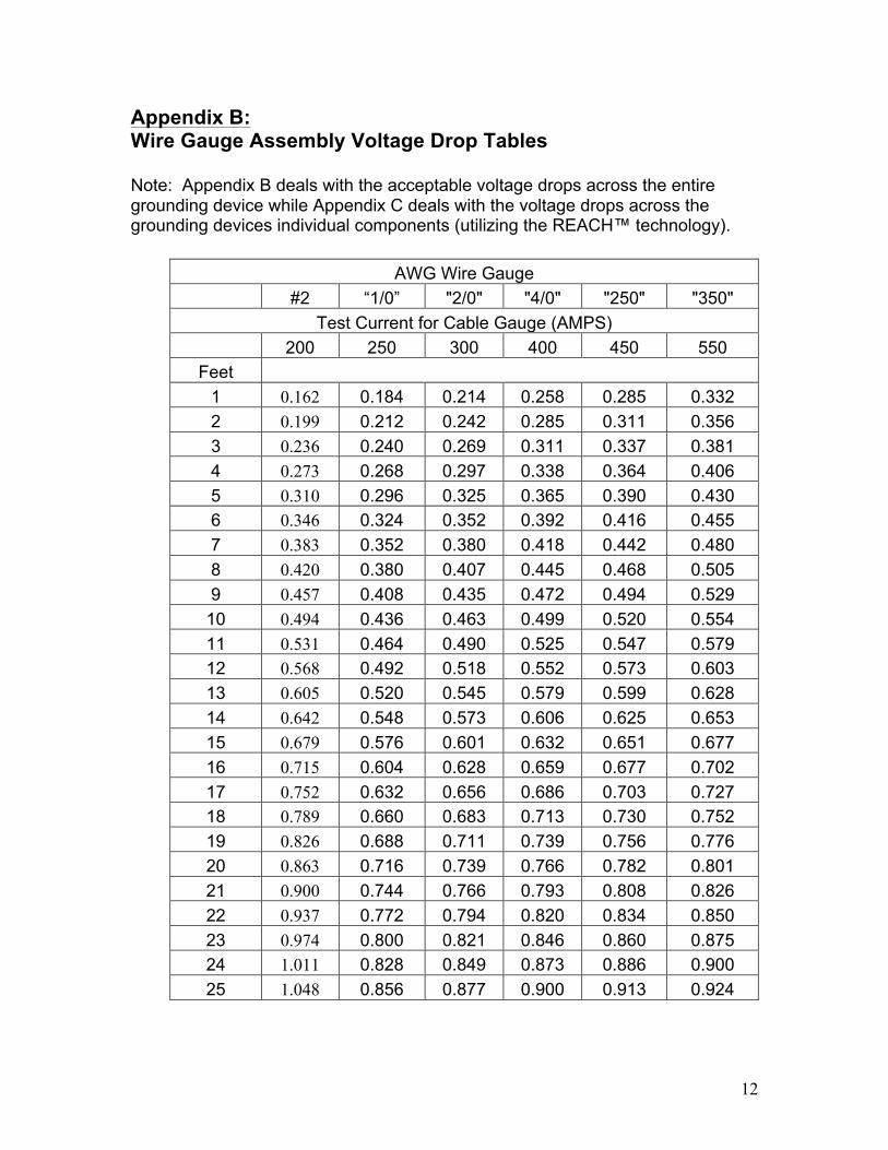
Appendix B: Wire Gauge Assembly Voltage Drop Tables Note: Appendix B deals with the acceptable voltage drops across the entire grounding device while Appendix C deals with the voltage drops across the grounding devices individual components (utilizing the REACH™ technology).
AWG Wire Gauge #2 “1/0” "2/0" "4/0" "250" "350"
Test Current for Cable Gauge (AMPS) 200 250 300 400 450 550
Feet 1 0.162 0.184 0.214 0.258 0.285 0.332 2 0.199 0.212 0.242 0.285 0.311 0.356 3 0.236 0.240 0.269 0.311 0.337 0.381 4 0.273 0.268 0.297 0.338 0.364 0.406 5 0.310 0.296 0.325 0.365 0.390 0.430 6 0.346 0.324 0.352 0.392 0.416 0.455 7 0.383 0.352 0.380 0.418 0.442 0.480 8 0.420 0.380 0.407 0.445 0.468 0.505 9 0.457 0.408 0.435 0.472 0.494 0.529
10 0.494 0.436 0.463 0.499 0.520 0.554 11 0.531 0.464 0.490 0.525 0.547 0.579 12 0.568 0.492 0.518 0.552 0.573 0.603 13 0.605 0.520 0.545 0.579 0.599 0.628 14 0.642 0.548 0.573 0.606 0.625 0.653 15 0.679 0.576 0.601 0.632 0.651 0.677 16 0.715 0.604 0.628 0.659 0.677 0.702 17 0.752 0.632 0.656 0.686 0.703 0.727 18 0.789 0.660 0.683 0.713 0.730 0.752 19 0.826 0.688 0.711 0.739 0.756 0.776 20 0.863 0.716 0.739 0.766 0.782 0.801 21 0.900 0.744 0.766 0.793 0.808 0.826 22 0.937 0.772 0.794 0.820 0.834 0.850 23 0.974 0.800 0.821 0.846 0.860 0.875 24 1.011 0.828 0.849 0.873 0.886 0.900 25 1.048 0.856 0.877 0.900 0.913 0.924
13
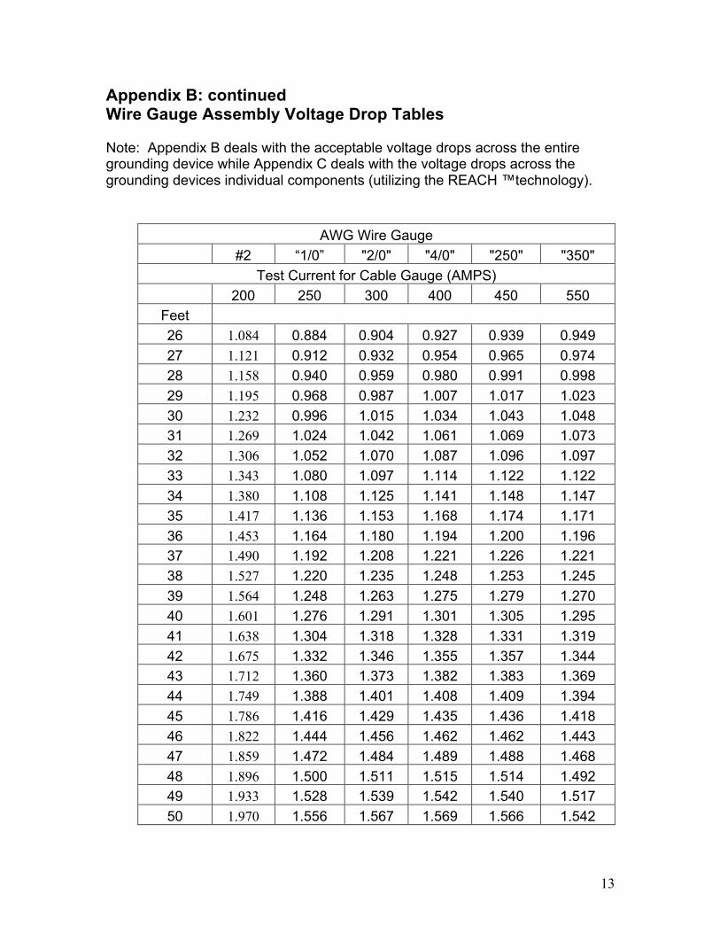
Appendix B: continued Wire Gauge Assembly Voltage Drop Tables Note: Appendix B deals with the acceptable voltage drops across the entire grounding device while Appendix C deals with the voltage drops across the grounding devices individual components (utilizing the REACH ™technology).
AWG Wire Gauge #2 “1/0” "2/0" "4/0" "250" "350"
Test Current for Cable Gauge (AMPS) 200 250 300 400 450 550
Feet 26 1.084 0.884 0.904 0.927 0.939 0.949 27 1.121 0.912 0.932 0.954 0.965 0.974 28 1.158 0.940 0.959 0.980 0.991 0.998 29 1.195 0.968 0.987 1.007 1.017 1.023 30 1.232 0.996 1.015 1.034 1.043 1.048 31 1.269 1.024 1.042 1.061 1.069 1.073 32 1.306 1.052 1.070 1.087 1.096 1.097 33 1.343 1.080 1.097 1.114 1.122 1.122 34 1.380 1.108 1.125 1.141 1.148 1.147 35 1.417 1.136 1.153 1.168 1.174 1.171 36 1.453 1.164 1.180 1.194 1.200 1.196 37 1.490 1.192 1.208 1.221 1.226 1.221 38 1.527 1.220 1.235 1.248 1.253 1.245 39 1.564 1.248 1.263 1.275 1.279 1.270 40 1.601 1.276 1.291 1.301 1.305 1.295 41 1.638 1.304 1.318 1.328 1.331 1.319 42 1.675 1.332 1.346 1.355 1.357 1.344 43 1.712 1.360 1.373 1.382 1.383 1.369 44 1.749 1.388 1.401 1.408 1.409 1.394 45 1.786 1.416 1.429 1.435 1.436 1.418 46 1.822 1.444 1.456 1.462 1.462 1.443 47 1.859 1.472 1.484 1.489 1.488 1.468 48 1.896 1.500 1.511 1.515 1.514 1.492 49 1.933 1.528 1.539 1.542 1.540 1.517 50 1.970 1.556 1.567 1.569 1.566 1.542

14
Appendix B: continued Wire Gauge Assembly Voltage Drop Tables Note: Appendix B deals with the acceptable voltage drops across the entire grounding device while Appendix C deals with the voltage drops across the grounding devices individual components (utilizing the REACH™ technology).
AWG Wire Gauge #2 “1/0” "2/0" "4/0" "250" "350"
Test Current for Cable Gauge (AMPS) 200 250 300 400 450 550
Feet Voltage Drop 51 2.007 1.584 1.594 1.596 1.592 1.566 52 2.044 1.612 1.622 1.623 1.619 1.591 53 2.081 1.640 1.649 1.649 1.645 1.616 54 2.118 1.668 1.677 1.676 1.671 1.641 55 2.155 1.696 1.705 1.703 1.697 1.665 56 2.191 1.724 1.732 1.730 1.723 1.690 57 2.228 1.752 1.760 1.756 1.749 1.715 58 2.265 1.780 1.787 1.783 1.775 1.739 59 2.302 1.808 1.815 1.810 1.802 1.764 60 2.339 1.836 1.843 1.837 1.828 1.789 61 2.376 1.864 1.870 1.863 1.854 1.813 62 2.413 1.892 1.898 1.890 1.880 1.838 63 2.450 1.920 1.925 1.917 1.906 1.863 64 2.487 1.948 1.953 1.944 1.932 1.887 65 2.524 1.976 1.981 1.970 1.958 1.912 66 2.560 2.004 2.008 1.997 1.985 1.937 67 2.597 2.032 2.036 2.024 2.011 1.962 68 2.634 2.060 2.063 2.051 2.037 1.986 69 2.671 2.088 2.091 2.077 2.063 2.011 70 2.708 2.116 2.119 2.104 2.089 2.036 71 2.745 2.144 2.146 2.131 2.115 2.060 72 2.782 2.172 2.174 2.158 2.141 2.085 73 2.819 2.200 2.201 2.184 2.168 2.110 74 2.856 2.228 2.229 2.211 2.194 2.134 75 2.893 2.256 2.257 2.238 2.220 2.159

15
Appendix B: continued Wire Gauge Assembly Voltage Drop Tables Note: Appendix B deals with the acceptable voltage drops across the entire grounding device while Appendix C deals with the voltage drops across the grounding devices individual components (utilizing the REACH™ technology).
AWG Wire Gauge #2 “1/0” "2/0" "4/0" "250" "350"
Test Current for Cable Gauge (AMPS) 200 250 300 400 450 550
Feet Voltage Drop 76 2.284 2.284 2.265 2.246 2.184 77 2.312 2.312 2.292 2.272 2.209 78 2.340 2.339 2.318 2.298 2.233 79 2.368 2.367 2.345 2.324 2.258 80 2.396 2.395 2.372 2.351 2.283 81 2.424 2.422 2.399 2.377 2.307 82 2.452 2.450 2.425 2.403 2.332 83 2.480 2.477 2.452 2.429 2.357 84 2.508 2.505 2.479 2.455 2.381 85 2.536 2.533 2.506 2.481 2.406 86 2.564 2.560 2.532 2.507 2.431 87 2.592 2.588 2.559 2.534 2.455 88 2.620 2.615 2.586 2.560 2.480 89 2.648 2.643 2.613 2.586 2.505 90 2.676 2.671 2.639 2.612 2.530 91 2.704 2.698 2.666 2.638 2.554 92 2.732 2.726 2.693 2.664 2.579 93 2.760 2.753 2.720 2.690 2.604 94 2.788 2.781 2.746 2.717 2.628 95 2.816 2.809 2.773 2.743 2.653 96 2.844 2.836 2.800 2.769 2.678 97 2.872 2.864 2.827 2.795 2.702 98 2.900 2.891 2.853 2.821 2.727 99 2.928 2.919 2.880 2.847 2.752
100 2.956 2.947 2.907 2.874 2.777

16
Appendix C: #2 Cable Component Voltage Drop Note: Appendix B deals with the acceptable voltage drops across the entire grounding device while Appendix C deals with the voltage drops across the grounding devices individual components (utilizing the REACH™ technology). Test Current – 200A Ohms per ft 0.000185 Clamp to Ferrule 0.031V Ferrule to Cable 0.031V Clamp to Conductor 0.062V
Cable Length (Feet)
Cable Voltage Drop (Volts)
1 0.037 2 0.074 3 0.111 4 0.148 5 0.185 6 0.221 7 0.258 8 0.295 9 0.332
10 0.369 11 0.406 12 0.443 13 0.480 14 0.517 15 0.554 16 0.590 17 0.627 18 0.664 19 0.701 20 0.738 21 0.775 22 0.812 23 0.849 24 0.886 25 0.923
For longer lengths multiply by whole numbers. Example: multiply 25 ft volt drop by 4 to obtain reading for 100 foot length.

17
Appendix C (continued) 1/0 Cable Component Voltage Drop Note: Appendix B deals with the acceptable voltage drops across the entire grounding device while Appendix C deals with the voltage drops across the grounding devices individual components (utilizing the REACH™ technology). Test Current – 250A Ohms per ft 0.000112 Clamp to Ferrule 0.039V Ferrule to Cable 0.039V Clamp to conductor 0.078V
Cable Length (feet)
Voltage Drop (volts)
1 0.028 2 0.056 3 0.084 4 0.112 5 0.140 6 0.168 7 0.196 8 0.224 9 0.252
10 0.280 11 0.308 12 0.336 13 0.364 14 0.392 15 0.420 16 0.448 17 0.476 18 0.504 19 0.532 20 0.560 21 0.588 22 0.616 23 0.644 24 0.672 25 0.700
For longer lengths multiply by whole numbers. Example: multiply 25 ft volt drop by 4 to obtain reading for 100 foot length.
18
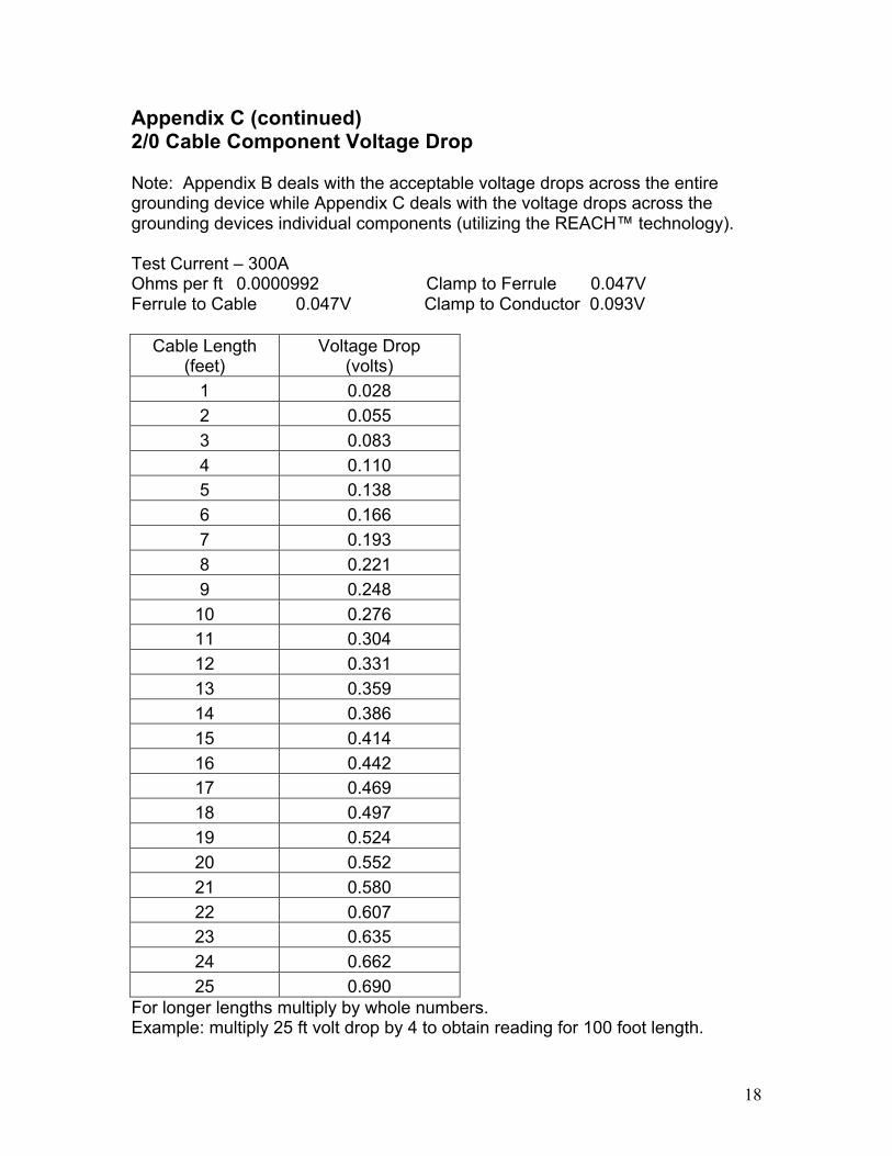
Appendix C (continued) 2/0 Cable Component Voltage Drop Note: Appendix B deals with the acceptable voltage drops across the entire grounding device while Appendix C deals with the voltage drops across the grounding devices individual components (utilizing the REACH™ technology). Test Current – 300A Ohms per ft 0.0000992 Clamp to Ferrule 0.047V Ferrule to Cable 0.047V Clamp to Conductor 0.093V
Cable Length (feet)
Voltage Drop (volts)
1 0.028 2 0.055 3 0.083 4 0.110 5 0.138 6 0.166 7 0.193 8 0.221 9 0.248
10 0.276 11 0.304 12 0.331 13 0.359 14 0.386 15 0.414 16 0.442 17 0.469 18 0.497 19 0.524 20 0.552 21 0.580 22 0.607 23 0.635 24 0.662 25 0.690
For longer lengths multiply by whole numbers. Example: multiply 25 ft volt drop by 4 to obtain reading for 100 foot length.

19
Appendix C (continued) 4/0 Cable Component Voltage Drop Note: Appendix B deals with the acceptable voltage drops across the entire grounding device while Appendix C deals with the voltage drops across the grounding devices individual components (utilizing the REACH™ technology). Test Current – 400A Ohms per ft 0.0000669 Clamp to Ferrule 0.059V Ferrule to Cable 0.059V Clamp to Conductor 0.118V
Cable Length (feet)
Voltage Drop (volts)
1 0.027 2 0.054 3 0.080 4 0.107 5 0.134 6 0.161 7 0.187 8 0.214 9 0.241
10 0.268 11 0.294 12 0.321 13 0.348 14 0.375 15 0.401 16 0.428 17 0.455 18 0.482 19 0.508 20 0.535 21 0.562 22 0.589 23 0.615 24 0.642 25 0.669
For longer lengths multiply by whole numbers. Example: multiply 25 ft volt drop by 4 to obtain reading for 100 foot length.

20
Appendix C (continued) 250 kcmil or double 2/0 Cable Component Voltage Drop Note: Appendix B deals with the acceptable voltage drops across the entire grounding device while Appendix C deals with the voltage drops across the grounding devices individual components (utilizing the REACH™ technology). Test Current – 450A Ohms per ft 0.0000581 Clamp to Ferrule 0.065V Ferrule to Cable 0.065V Clamp to Conductor 0.130V
Cable Length (feet)
Voltage Drop (volts)
1 0.026 2 0.052 3 0.078 4 0.105 5 0.131 6 0.157 7 0.183 8 0.209 9 0.235
10 0.261 11 0.288 12 0.314 13 0.340 14 0.366 15 0.392 16 0.418 17 0.444 18 0.471 19 0.497 20 0.523 21 0.549 22 0.575 23 0.601 24 0.627 25 0.654
For longer lengths multiply by whole numbers. Example: multiply 25 ft volt drop by 4 to obtain reading for 100 foot length.

21
Appendix C (continued) 350 kcmil or double 4/0 Cable Component Voltage Drop Note: Appendix B deals with the acceptable voltage drops across the entire grounding device while Appendix C deals with the voltage drops across the grounding devices individual components (utilizing the REACH™ technology). Test Current – 550A Ohms per ft 0.0000449 Clamp to Ferrule 0.077V Ferrule to Cable 0.077V Clamp to conductor 0.153V
Cable Length (feet)
Voltage Drop (volts)
1 0.025 2 0.049 3 0.074 4 0.099 5 0.123 6 0.148 7 0.173 8 0.198 9 0.222
10 0.247 11 0.272 12 0.296 13 0.321 14 0.346 15 0.370 16 0.395 17 0.420 18 0.445 19 0.469 20 0.494 21 0.519 22 0.543 23 0.568 24 0.593 25 0.617
For longer lengths multiply by whole numbers. Example: multiply 25 ft volt drop by 4 to obtain reading for 100 foot length.

22
Appendix D: Sample Record Keeping Chart Company: XYZ Power Utilities
Serial Number Original
Date Next Test
Date Cable Length
(Ft)
Type S or C
Initial Reading
Final Reading
Pg-1023 3/14/2001 3/14/2004 6 S 0.23 0.25
SN2315 – A 1/15/2002 1/1/2005 8 C 0.31 0.32 SN2315 – B 1/15/2002 1/1/2005 8 C 0.3 0.33 SN2315 – C 1/15/2002 1/1/2005 8 C 0.32 0.33
Scrap 1122452 10/25/03 10/25/04 25 S .97 1.65
A Type Code of S denotes a single ground jumper assembly, while a Type Code of C will denote a cluster assembly. Note that the number and lengths of the individual ‘arms’ in the cluster assembly can also be easily tracked. Cable assemblies found to be bad or not repairable may also be identified and “scrapped” in the system.

23

24
Chart 1 - Grounding Cable Ratings
ASTM F855 – Standard Specifications for Temporary Grounding Systems to Be Used on De-energized Electric Power Lines and Equipment
CHART 1 - GROUNDING CABLE RATINGS Short Circuit Properties (A) Withstand Rating
Symmetrical kA RMS 60 Hz Ultimate Capacity Symmetrical kA RMS 60 Hz
Grounding .. Continuous Cable Size 15 cycles 30 cycles 6 cycles 15 cycles 30 cycles 60 cycles Current Rating Copper (250 MS) (500 MS) (100 MS) (250 MS) (500MS) (1 s) RMS 60 Hz #2 14.5 10 29 18 13 9 200 1/0 21 15 47 29 21 14 250 2/0 27 20 59 37 26 18 300 3/0 36 25 74 47 33 23 350 4/0 43 30 94 59 42 29 400 250 kcmil 54 39 111 70 49 35 450 350 kcmil 74 54 155 98 69 49 550
A. Withstand and ultimate short circuit properties are based on performance with surges not exceeding a 20% asymmetry factor. Consult ASTM F855-03 standard for additional information and complete specifications.