operational manual for the hv-x validator · hamilton tokenotes® are being used. ... tokenotesÒ...
TRANSCRIPT
Document #101-0029 12/26/02
Operational Manual for the
HV-X Validator

Document #101-0029 Page 2 of 26 12/26/02
ABOUT THIS MANUAL This manual will enable the operator to complete basic maintenance, identify error codes, and perform basic troubleshooting. An electrical connection diagram and Validator package dimensions are provided to assist operators in customizing the Validator to individual needs. There are no user serviceable parts inside the Validator. Further technical assistance can be obtained by calling (800) 837-5561 or (419) 867-4858. When calling for service, it is important to have the serial number readily available. Please take the time to record this number in the space provided.
VALIDATOR SERIAL #__________________________________

Document #101-0029 Page 3 of 26 12/26/02
TABLE OF CONTENTS
I. INTRODUCTION.................................................................................4
II. SWITCH SETTINGS .....................................................................5 - 7
III. ELECTRICAL CONNECTIONS ........................................................8 9-PIN CONNECTOR....................................................................................................... 8
EXTERNAL VIEW............................................................................................................8 WIRE VIEW ....................................................................................................................8
IV. TESTING...........................................................................................9
V. MAINTENANCE ...............................................................................10 MONTHLY ....................................................................................................................10 YEARLY ........................................................................................................................10
VI. RETURNING ITEMS FOR SERVICE .............................................11
VII. PARTS ...........................................................................................12
VIII. ERROR CODES.................................................................... 13 - 22 TROUBLESHOOTING ..........................................................................................14 - 22
TOKENOTE® PROGRAMMING ERRORS ...................................................................... 14 STANDARD BILL OPERATION............................................................................... 15 - 22
APPENDICES
APPENDIX A - HV-X Validator Dimensions......................................23
Document #101-0029 Page 4 of 26 12/26/02
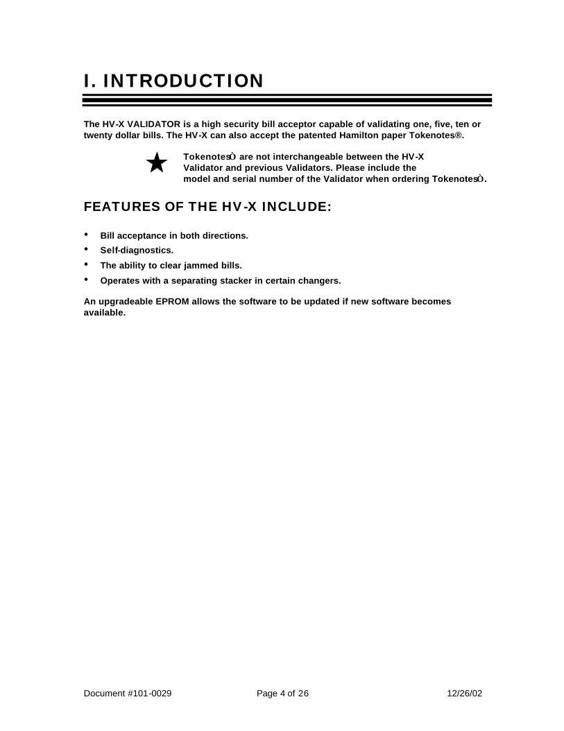
I. INTRODUCTION The HV-X VALIDATOR is a high security bill acceptor capable of validating one, five, ten or twenty dollar bills. The HV-X can also accept the patented Hamilton paper Tokenotes®.
Tokenotes are not interchangeable between the HV-X Validator and previous Validators. Please include the model and serial number of the Validator when ordering Tokenotes.
FEATURES OF THE HV-X INCLUDE:
• Bill acceptance in both directions.
• Self-diagnostics.
• The ability to clear jammed bills.
• Operates with a separating stacker in certain changers. An upgradeable EPROM allows the software to be updated if new software becomes available.
Document #101-0029 Page 5 of 26 12/26/02
II. SWITCH SETTINGS
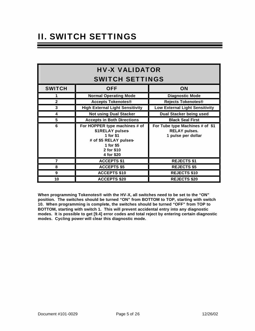
HV-X VALIDATOR SWITCH SETTINGS
SWITCH OFF ON 1 Normal Operating Mode Diagnostic Mode 2 Accepts Tokenotes® Rejects Tokenotes® 3 High External Light Sensitivity Low External Light Sensitivity
4 Not using Dual Stacker Dual Stacker being used 5 Accepts in Both Directions Black Seal First 6 For HOPPER type machines # of
$1RELAY pulses- 1 for $1
# of $5 RELAY pulses- 1 for $5
2 for $10 4 for $20
For Tube type Machines # of $1 RELAY pulses.
1 pulse per dollar
7 ACCEPTS $1 REJECTS $1 8 ACCEPTS $5 REJECTS $5 9 ACCEPTS $10 REJECTS $10
10 ACCEPTS $20 REJECTS $20 When programming Tokenotes® with the HV-X, all switches need to be set to the “ON” position. The switches should be turned “ON” from BOTTOM to TOP, starting with switch 10. When programming is complete, the switches should be turned “OFF” from TOP to BOTTOM, starting with switch 1. This will prevent accidental entry into any diagnostic modes. It is possible to get [9.4] error codes and total reject by entering certain diagnostic modes. Cycling power will clear this diagnostic mode.

Document #101-0029 Page 6 of 26 12/26/02
Switch 1: Switch #1 should ALWAYS be in the OFF position. The Validator will not function properly otherwise.
Switch 2: Switch #2 should be in the ON position unless the new Hamilton Tokenotes® are being used. If they are being used, this switch should be moved to the OFF position.
Tokenotes for the HV-X Validator have been printed using improved techniques for code generation and acceptance. Because of this step forward in Tokenote technology, these new Tokenotes and Tokenotes purchased for use with previous Validators are not interchangeable.
When the #2 switch is ON, the Validator rejects Tokenotes already programmed in.
Switch 3: Switch #3 should be in the OFF position.
Switch 4: Switch #4 should be in the OFF position unless the Hamilton Separating Stacker is being used.
Switch 5: Switch #5 selects which direction the Validator will accept an inserted bill. If this switch is OFF, the Validator will accept bills face up in either direction. If this switch is ON, the Validator will only accept bills face up and the end with the black seal inserted first.
Switch 6: Switch #6 selects how the Validator signals the dispensing equipment after accepting a bill. If this switch is OFF, the Validator will activate the $1 Relay once for an accepted $1 bill, the $5 Relay once for an accepted
$5 bill, the $5 Relay twice for an accepted $10 bill, and the $5 Relay four times for an accepted $20 bill. If switch #6 is ON, the Validator will activate the $1 Relay once for an accepted $1 bill, the $1 Relay five times for an accepted $5 bill, the $1 Relay ten times for an accepted $10 bill, and the $1 relay Twenty times for an accepted $20 bill. SWITCH #6 DOES NOT WORK WITH TUBE TYPE CHANGERS.
Switch 7: Switch #7 selects whether the Validator will accept or reject $1 bills. If the switch is in the OFF position, the Validator will accept $1 bills. If the switch is ON, the Validator will reject $1 bills.
Document #101-0029 Page 7 of 26 12/26/02
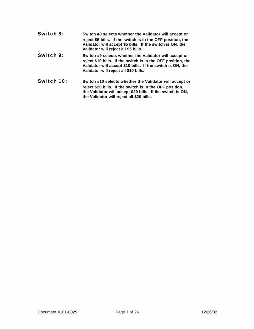
Switch 8: Switch #8 selects whether the Validator will accept or reject $5 bills. If the switch is in the OFF position, the Validator will accept $5 bills. If the switch is ON, the Validator will reject all $5 bills.
Switch 9: Switch #9 selects whether the Validator will accept or reject $10 bills. If the switch is in the OFF position, the Validator will accept $10 bills. If the switch is ON, the Validator will reject all $10 bills.
Switch 10: Switch #10 selects whether the Validator will accept or reject $20 bills. If the switch is in the OFF position, the Validator will accept $20 bills. If the switch is ON, the Validator will reject all $20 bills.
Document #101-0029 Page 8 of 26 12/26/02
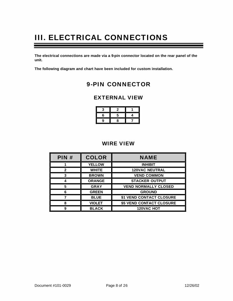
III. ELECTRICAL CONNECTIONS The electrical connections are made via a 9-pin connector located on the rear panel of the unit. The following diagram and chart have been included for custom installation.
9-PIN CONNECTOR
EXTERNAL VIEW
3 2 1
6 5 4 9 8 7
WIRE VIEW
PIN # COLOR NAME 1 YELLOW INHIBIT 2 WHITE 120VAC NEUTRAL 3 BROWN VEND COMMON 4 ORANGE STACKER OUTPUT
5 GRAY VEND NORMALLY CLOSED 6 GREEN GROUND 7 BLUE $1 VEND CONTACT CLOSURE
8 VIOLET $5 VEND CONTACT CLOSURE 9 BLACK 120VAC HOT
Document #101-0029 Page 9 of 26 12/26/02
IV. TESTING
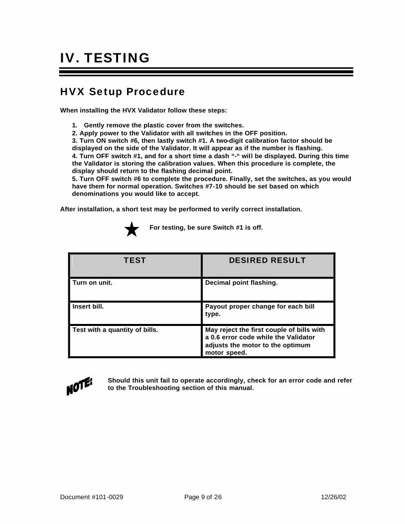
HVX Setup Procedure When installing the HVX Validator follow these steps:
1. Gently remove the plastic cover from the switches. 2. Apply power to the Validator with all switches in the OFF position. 3. Turn ON switch #6, then lastly switch #1. A two-digit calibration factor should be displayed on the side of the Validator. It will appear as if the number is flashing. 4. Turn OFF switch #1, and for a short time a dash “-“ will be displayed. During this time the Validator is storing the calibration values. When this procedure is complete, the display should return to the flashing decimal point. 5. Turn OFF switch #6 to complete the procedure. Finally, set the switches, as you would have them for normal operation. Switches #7-10 should be set based on which denominations you would like to accept.
After installation, a short test may be performed to verify correct installation.
For testing, be sure Switch #1 is off.
TEST DESIRED RESULT
Turn on unit. Decimal point flashing.
Insert bill. Payout proper change for each bill type.
Test with a quantity of bills. May reject the first couple of bills with a 0.6 error code while the Validator adjusts the motor to the optimum motor speed.
Should this unit fail to operate accordingly, check for an error code and refer to the Troubleshooting section of this manual.
Document #101-0029 Page 10 of 26 12/26/02
V. MAINTENANCE
MONTHLY - Depending on use
1. The platen assembly should be opened and cleaned regularly.
2. To open the platen assembly:
• Unplug the changer. • Disconnect the 9-pin plug. • Remove the Validator from the holder. • Loosen the 2 thumbscrews on both sides of the Validator. • Carefully lift to open from the bill insert end of the Validator.
3. Clean rollers, heads and sensors with cotton swabs and rubbing alcohol. DO NOT
ALLOW ALCOHOL TO CONTAMINATE THE BELTS.
4. Close the Platen Assembly and re-tighten the LATCH STUDS. Loose LATCH STUDS may cause false error codes.
YEARLY The HV-X Validator should be serviced annually to maintain maximum performance. THIS WORK SHOULD ONLY BE DONE BY A TRAINED TECHNICIAN.
Document #101-0029 Page 11 of 26 12/26/02
VI. RETURNING ITEMS FOR SERVICE If any part or component must be shipped to the distributor or the manufacturer for replacement or repair, the following procedure is used:
• CALL BEFORE SHIPPING. BE READY WITH THE MACHINE SERIAL NUMBER AND THE COMPONENT SERIAL NUMBER. YOU WILL RECEIVE A RETURN AUTHORIZATION NUMBER (RA NUMBER). WRITE THE RA NUMBER ON THE OUTSIDE OF THE BOX YOU ARE USING TO RETURN THE COMPONENT, AS WELL AS ON AN ENCLOSED NOTE.
• If shipping components, first place in a plastic bag before putting in a box and surrounding with good packing material.
• Ship via UNITED PARCEL SERVICE (UPS) if at all possible.
• If shipped by U.S. Postal Service (Parcel Post), send by SPECIAL HANDLING.
• Adequately insure shipments; if uncertain about the value, call the distributor or the manufacturer for information.
• Include a note in shipment describing the nature of the problem, along with a full return address. WE CANNOT RETURN SHIPMENTS TO POST OFFICE BOXES. Be sure to include the RA Number.
• Please include your NAME and a TELEPHONE NUMBER where you can be reached.
Document #101-0029 Page 12 of 26 12/26/02
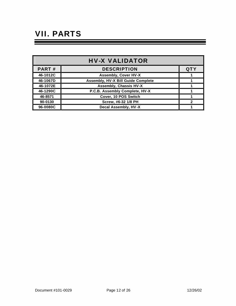
VII. PARTS
HV-X VALIDATOR PART # DESCRIPTION QTY 46-1012C Assembly, Cover HV-X 1 46-1067D Assembly, HV-X Bill Guide Complete 1 46-1072E Assembly, Chassis HV-X 1 46-1290C P.C.B. Assembly Complete, HV-X 1 46-8571 Cover, 10 POS Switch 1 90-0130 Screw, #6-32 1/8 PH 2
96-0080C Decal Assembly, HV -X 1

Document #101-0029 Page 13 of 26 12/26/02
VIII. ERROR CODES The HV-X provides a diagnostic code for most problems. Upon any problem, the error code should be checked first. The display is only a single digit; therefore, to obtain the 2-digit error code the first digit is displayed WITH THE DECIMAL POINT (5.) and the second digit is displayed WITHOUT THE DECIMAL POINT (3). The display will continue to flash the 2-digit error code; one digit at a time, until the failure is corrected or power is removed.
During normal operation only the decimal point should flash. Do not be concerned if one of the segments flashes once upon power-up or upon passing a valid bill.
Document #101-0029 Page 14 of 26 12/26/02
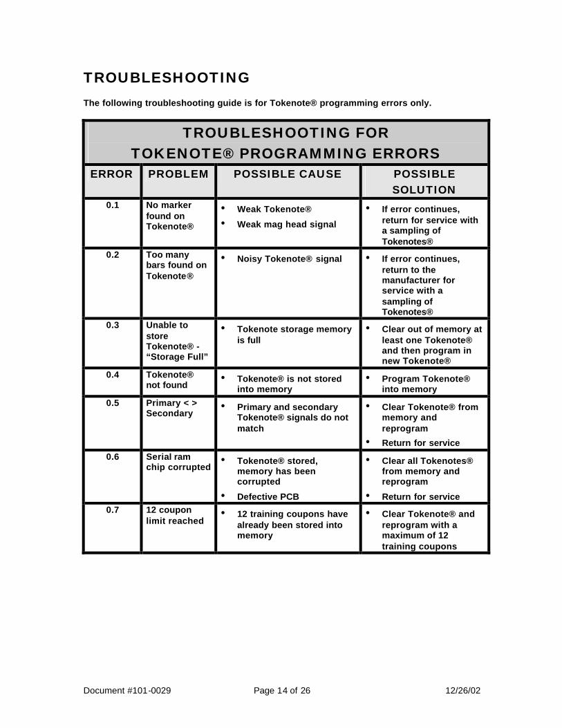
TROUBLESHOOTING The following troubleshooting guide is for Tokenote® programming errors only.
TROUBLESHOOTING FOR TOKENOTE® PROGRAMMING ERRORS
ERROR PROBLEM POSSIBLE CAUSE POSSIBLE SOLUTION
0.1 No marker found on Tokenote®
• Weak Tokenote® • Weak mag head signal
• If error continues, return for service with a sampling of Tokenotes®
0.2 Too many bars found on Tokenote®
• Noisy Tokenote® signal • If error continues, return to the manufacturer for service with a sampling of Tokenotes®
0.3 Unable to store Tokenote® - “Storage Full”
• Tokenote storage memory is full
• Clear out of memory at least one Tokenote® and then program in new Tokenote®
0.4 Tokenote® not found
• Tokenote® is not stored into memory
• Program Tokenote® into memory
0.5 Primary < > Secondary
• Primary and secondary Tokenote® signals do not match
• Clear Tokenote® from memory and reprogram
• Return for service
0.6 Serial ram chip corrupted
• Tokenote® stored, memory has been corrupted
• Defective PCB
• Clear all Tokenotes® from memory and reprogram
• Return for service 0.7 12 coupon
limit reached • 12 training coupons have
already been stored into memory
• Clear Tokenote® and reprogram with a maximum of 12 training coupons
Document #101-0029 Page 15 of 26 12/26/02
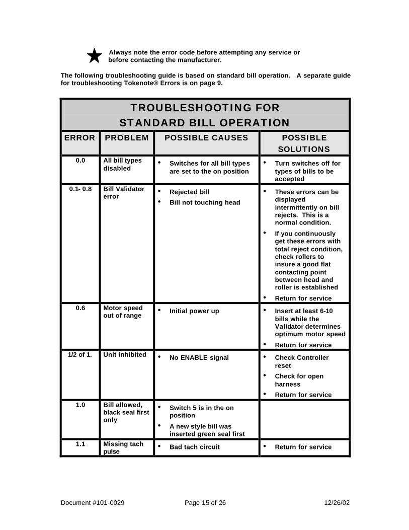
Always note the error code before attempting any service or before contacting the manufacturer. The following troubleshooting guide is based on standard bill operation. A separate guide for troubleshooting Tokenote® Errors is on page 9.
TROUBLESHOOTING FOR STANDARD BILL OPERATION
ERROR PROBLEM POSSIBLE CAUSES POSSIBLE SOLUTIONS
0.0 All bill types disabled
• Switches for all bill types are set to the on position
• Turn switches off for types of bills to be accepted
0.1- 0.8 Bill Validator error
• Rejected bill
• Bill not touching head
• These errors can be displayed intermittently on bill rejects. This is a normal condition.
• If you continuously get these errors with total reject condition, check rollers to insure a good flat contacting point between head and roller is established
• Return for service 0.6 Motor speed
out of range • Initial power up
• Insert at least 6-10 bills while the Validator determines optimum motor speed
• Return for service 1/2 of 1. Unit inhibited • No ENABLE signal • Check Controller
reset
• Check for open harness
• Return for service
1.0 Bill allowed, black seal first only
• Switch 5 is in the on position
• A new style bill was inserted green seal first
1.1 Missing tach pulse
• Bad tach circuit • Return for service
Document #101-0029 Page 16 of 26 12/26/02
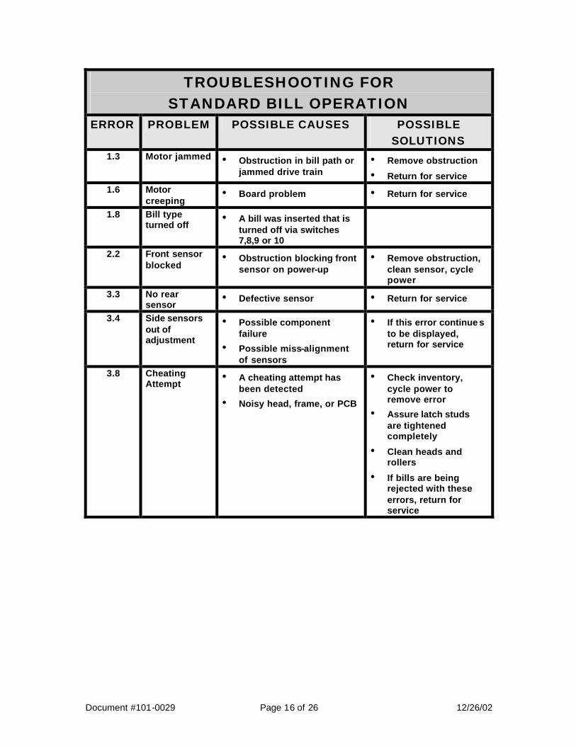
TROUBLESHOOTING FOR STANDARD BILL OPERATION
ERROR PROBLEM POSSIBLE CAUSES POSSIBLE SOLUTIONS
1.3 Motor jammed • Obstruction in bill path or jammed drive train
• Remove obstruction
• Return for service 1.6 Motor
creeping • Board problem • Return for service
1.8 Bill type turned off
• A bill was inserted that is turned off via switches 7,8,9 or 10
2.2 Front sensor blocked
• Obstruction blocking front sensor on power-up
• Remove obstruction, clean sensor, cycle power
3.3 No rear sensor
• Defective sensor • Return for service
3.4 Side sensors out of adjustment
• Possible component failure
• Possible miss-alignment of sensors
• If this error continue s to be displayed, return for service
3.8 Cheating Attempt
• A cheating attempt has been detected
• Noisy head, frame, or PCB
• Check inventory, cycle power to remove error
• Assure latch studs are tightened completely
• Clean heads and rollers
• If bills are being rejected with these errors, return for service
Document #101-0029 Page 17 of 26 12/26/02
TROUBLESHOOTING FOR STANDARD BILL OPERATION
ERROR PROBLEM POSSIBLE CAUSES POSSIBLE SOLUTIONS
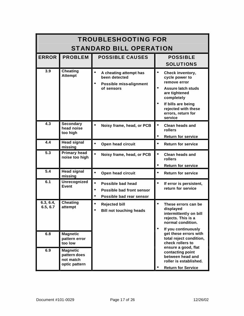
3.9 Cheating Attempt
• A cheating attempt has been detected
• Possible miss-alignment of sensors
• Check inventory, cycle power to remove error
• Assure latch studs are tightened completely
• If bills are being rejected with these errors, return for service
4.3 Secondary head noise too high
• Noisy frame, head, or PCB • Clean heads and rollers
• Return for service 4.4 Head signal
missing • Open head circuit • Return for service
5.3 Primary head noise too high
• Noisy frame, head, or PCB • Clean heads and rollers
• Return for service 5.4 Head signal
missing • Open head circuit • Return for service
6.1 Unrecognized Event
• Possible bad head
• Possible bad front sensor
• Possible bad rear sensor
• If error is persistent, return for service
6.3, 6.4, 6.5, 6.7
Cheating attempt
6.8 Magnetic pattern error too low
6.9 Magnetic pattern does not match optic pattern
• Rejected bill
• Bill not touching heads
• These errors can be displayed intermittently on bill rejects. This is a normal condition.
• If you continuously get these errors with total reject condition, check rollers to ensure a good, flat contacting point between head and roller is established.
• Return for Service

Document #101-0029 Page 18 of 26 12/26/02
TROUBLESHOOTING FOR STANDARD BILL OPERATION
ERROR
PROBLEM POSSIBLE CAUSES POSSIBLE SOLUTIONS
7.1 Cheating Attempt
• A cheating attempt has been detected
• Possible bad rear sensor
• Check inventory, cycle power to remove error
• Assure latch studs are tightened completely
• If bills are being rejected with these errors, return for service
7.2 Dual Stacker time-out
• Incorrect Controller or configuration switch setting
• Stacker jam
• Verify that the Controller is a v1.6 or greater, and configuration switch #6 is on, cycle power
• Clear jam
• Return for service 7.3 Cheating
Attempt • A cheating attempt has
been detected • Check inventory,
cycle power to remove error
• Assure latch studs are tightened completely
7.4, 7.5 Side sensors out of adjustment
• Possible component failure or vandalism
• If this error continues to be displayed, return for service
7.6 Cheating Attempt
• A cheating attempt has been detected
• Possible bad rear sensor
• Check inventory, cycle power to remove error
• Assure latch studs are tightened completely
• If bills are being rejected with these errors, return for service
7.7, 7.8, 7.9
Cheating Attempt
• A cheating attempt has been detected
• Defective head/motor circuit
• Check inventory, cycle power to remove error
• If this error continues to be displayed, return for service

Document #101-0029 Page 19 of 26 12/26/02
TROUBLESHOOTING FOR STANDARD BILL OPERATION
ERROR PROBLEM POSSIBLE CAUSES POSSIBLE SOLUTIONS
8.1 Optic pattern average too high
8.2 Optic pattern average too low
8.3 Optic pattern too flat
8.4 Optic error pattern too low
• Rejected bill
• Front sensor dirty
• These errors can be displayed intermittently on bill rejects. This is a normal condition.
• If you continuously get these errors with total reject condition, clean the front sensor with a little mild soapy water. Do not let excess water get into the Validator and do not use anything abrasive on the front sensor.
• Return for service
8.5 Rear sensor blocked on an accepted bill
• Obstruction blocking rear sensor. This will shut down the Validator and Controller causing a $1 input stuck on the Controller or a Validator shutdown error on a C2000 v1.5 or an Audit Pro v3.4 or greater
• Remove obstruction, clean sensor, cycle power, reset Controller
8.6 Rear sensor blocked on a rejected bill
• Obstruction blocking rear sensor. This will shut down the Validator and Controller causing a $1 input stuck on the Controller or a Validator shutdown error on a C2000 v1.5 or an Audit Pro v3.4 or greater
• Remove obstruction, clean sensor, cycle power, reset Controller
Document #101-0029 Page 20 of 26 12/26/02
TROUBLESHOOTING FOR STANDARD BILL OPERATION
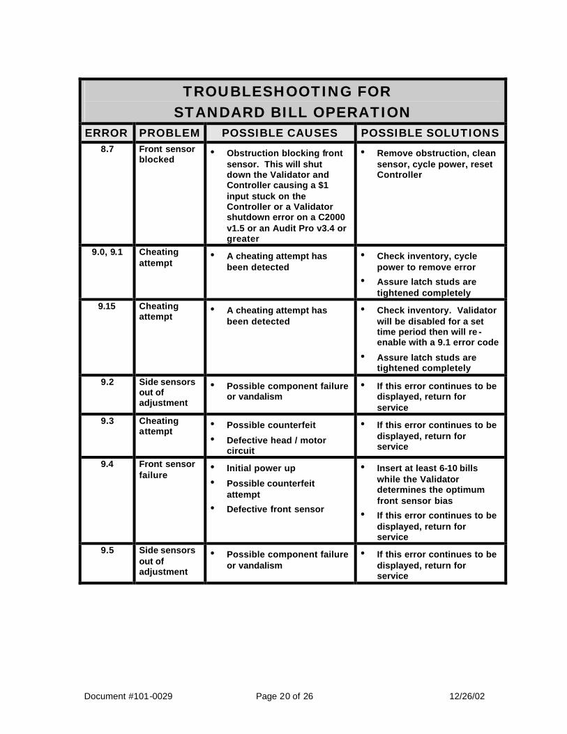
ERROR PROBLEM POSSIBLE CAUSES POSSIBLE SOLUTIONS 8.7
Front sensor blocked
• Obstruction blocking front sensor. This will shut down the Validator and Controller causing a $1 input stuck on the Controller or a Validator shutdown error on a C2000 v1.5 or an Audit Pro v3.4 or greater
• Remove obstruction, clean sensor, cycle power, reset Controller
9.0, 9.1 Cheating attempt
• A cheating attempt has been detected
• Check inventory, cycle power to remove error
• Assure latch studs are tightened completely
9.15 Cheating attempt
• A cheating attempt has been detected
• Check inventory. Validator will be disabled for a set time period then will re -enable with a 9.1 error code
• Assure latch studs are tightened completely
9.2 Side sensors out of adjustment
• Possible component failure or vandalism
• If this error continues to be displayed, return for service
9.3 Cheating attempt
• Possible counterfeit
• Defective head / motor circuit
• If this error continues to be displayed, return for service
9.4 Front sensor failure
• Initial power up
• Possible counterfeit attempt
• Defective front sensor
• Insert at least 6-10 bills while the Validator determines the optimum front sensor bias
• If this error continues to be displayed, return for service
9.5 Side sensors out of adjustment
• Possible component failure or vandalism
• If this error continues to be displayed, return for service

Document #101-0029 Page 21 of 26 12/26/02
TROUBLESHOOTING FOR STANDARD BILL OPERATION
ERROR PROBLEM POSSIBLE CAUSES POSSIBLE SOLUTIONS 9.7 Cheating
attempt
• A cheating attempt has previously been detected. On an HV-X v3.19 and earlier, this will shut down the Validator and Controller causing a $1 input stuck on the Controller or a Validator shutdown error on a C2000 v1.6 or an Audit Pro v3.4 or greater
• Defective head / motor circuit
• Check inventory, check for obstruction and remove. Cycle power, reset Controller
• If this error continues to be displayed, return for service
9.8 Cheating Attempt
• A cheating attempt has been detected
• Check inventory, cycle power to remove error
• Assure latch studs are tightened completely
P. Tokenote® programming mode
• All switches are turned ON. • Turn switches back to normal positions.
E.E 5 bills rejected in a row. Validator shuts down for approx. 10 seconds. If next bill is rejected, Validator will shut down for another 10 seconds until a valid bill is accepted, then CPU resets to normal mode.
• Bad bill
• Validator board or bill guide problem
• Run several bills
• Return for service
Document #101-0029 Page 22 of 26 12/26/02
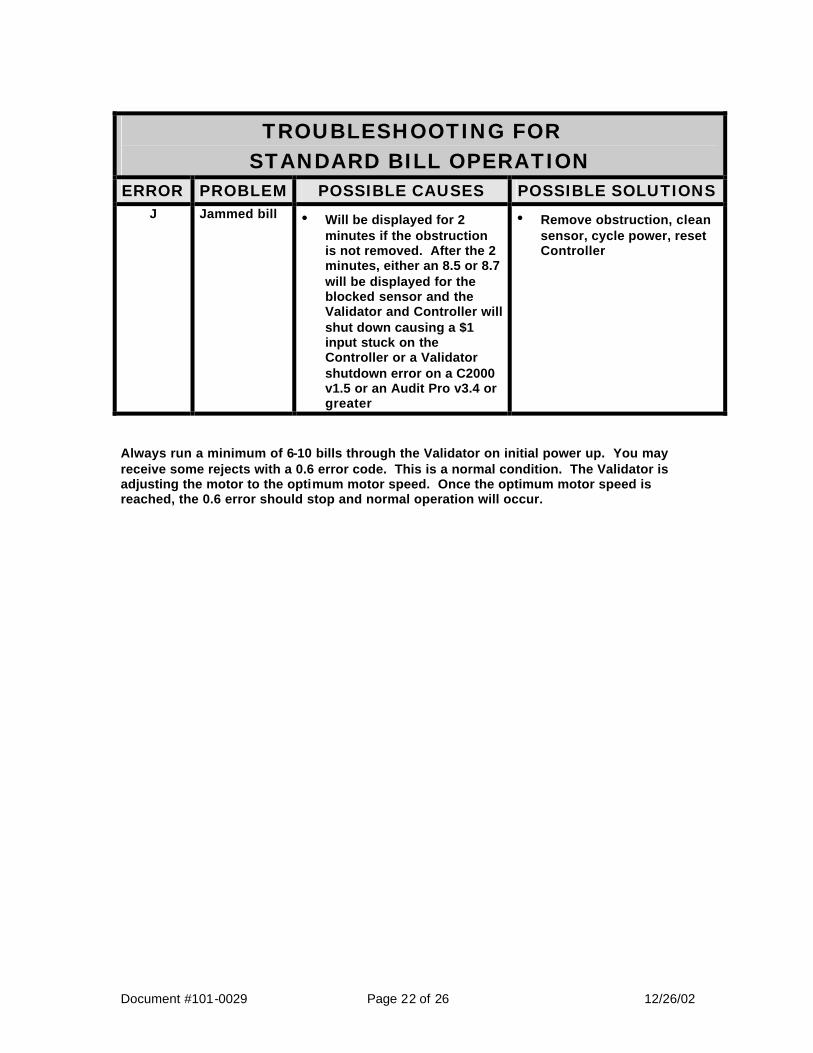
TROUBLESHOOTING FOR STANDARD BILL OPERATION
ERROR PROBLEM POSSIBLE CAUSES POSSIBLE SOLUTIONS J Jammed bill • Will be displayed for 2
minutes if the obstruction is not removed. After the 2 minutes, either an 8.5 or 8.7 will be displayed for the blocked sensor and the Validator and Controller will shut down causing a $1 input stuck on the Controller or a Validator shutdown error on a C2000 v1.5 or an Audit Pro v3.4 or greater
• Remove obstruction, clean sensor, cycle power, reset Controller
Always run a minimum of 6-10 bills through the Validator on initial power up. You may receive some rejects with a 0.6 error code. This is a normal condition. The Validator is adjusting the motor to the optimum motor speed. Once the optimum motor speed is reached, the 0.6 error should stop and normal operation will occur.
Document #101-0029 Page 23 of 26 12/26/02
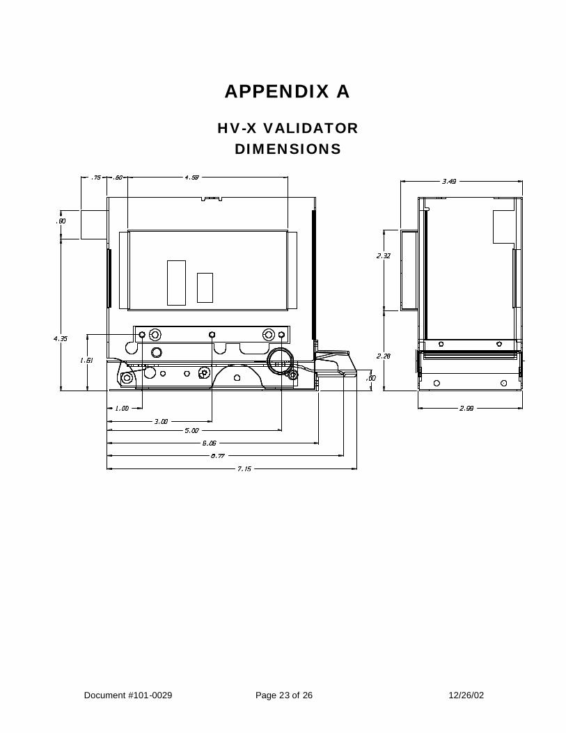
APPENDIX A
HV-X VALIDATOR DIMENSIONS

Document #101-0029 Page 24 of 26 12/26/02
LIMITED WARRANTY AGREEMENT OF HAMILTON MANUFACTURING CORP.
Hamilton Manufacturing Corp., an Ohio Corporation, (“Seller”) warrants to Purchaser that all new equipment shall be free from defects in material and factory workmanship for a period of one (1) year from the original shipping date. Hamilton Manufacturing Corp. further warrants if any part of said new equipment in Seller’s sole opinion, requires replacement or repair due to a defect in material or factory workmanship during said period, Seller will repair or replace said new equipment. Purchaser’s remedies and the liabilities and obligations of Seller herein shall be limited to repair or replacement of the equipment as Seller may choose, and Seller’s obligation to remedy such defects shall not exceed the Purchaser’s original cost for the equipment. Purchaser EXPRESSLY AGREES this is the EXCLUSIVE REMEDY under this warranty. There are no other express or implied warranties which extend beyond the face hereof. All warranty repair service must be performed by either a Factory Trained Service Representative or HAMILTON MANUFACTURING CORP., 1026 Hamilton Drive, Holland, Ohio 43528 PHONE (419) 867-4858 or (800) 837-5561, FAX (419) 867-4867. The limited warranty for new equipment is conditioned upon the following:
1. The subject equipment has not, in the Seller’s sole opinion, been subjected to: accident, abuse, misuse, vandalism, civil disobedience, riots, acts of God, natural disaster, acts of war or terrorism.
2. The Seller shall not be liable for any expense incurred by Purchaser incidental to the repair or replacement of equipment and Purchaser shall assume full responsibility for any freight or shipping charges.
3. The coverage of this warranty shall not extend to expendable parts.
4. Purchaser shall have a warranty registration card on file with Seller prior to any claim in order for warranty protection to apply.
5. No warranty coverage is applicable to any equipment used for currency other than that specified at the time of the purchase.
6. Seller expressly disclaims any warranty that counterfeit currency will not activate said equipment.
7. Seller expressly disclaims any warranty for any losses due to bill manipulation or theft or loss of cash under any circumstances.
Seller further warrants all repair or service work performed by a factory trained representative or Hamilton Manufacturing Corp. for a period of ninety (90) days from the date the repair or service work was performed. Purchaser’s remedies and the liabilities and obligations of Seller herein shall be limited to repair or replacement of equipment as Seller may choose, and Seller’s obligation to remedy such defects shall not exceed the Purchaser’s depreciated value of the equipment. Purchaser EXPRESSLY AGREES this is an EXCLUSIVE REMEDY under this warranty. There are no other express or implied warranties on repair or service work performed by a factory trained representative or Hamilton Manufacturing Corp. which extend beyond the face hereof.
(See next page for additional provisions)
Document #101-0029 Page 25 of 26 12/26/02
The limited warranty for repair and service work is conditioned upon the following:
1. The subject equipment has not, in the Seller’s sole opinion, been subjected to: accident, abuse, misuse, vandalism, civil disobedience, riots, acts of God, natural disaster, acts of war or terrorism.
2. The Seller shall not be liable for any expense incurred by Purchaser incidental to the repair or replacement of equipment and Purchaser shall assume full responsibility for any freight or shipping charges.
3. The coverage of this warranty shall not extend to expendable parts.
4. Purchaser shall have a warranty registration card on file with Seller prior to any claim in order for warranty protection to apply.
5. No warranty coverage is applicable to any equipment used for currency other than that specified at the time of the purchase.
6. Seller expressly disclaims any warranty that counterfeit currency will not activate said equipment.
7. Seller expressly disclaims any warranty for any losses due to bill manipulation or theft or loss of cash under any circumstances.
8. No person or entity other than a factory trained representative or Hamilton Manufacturing Corp. has performed or attempted to perform the subject repair or service.
THIS AGREEMENT IS MADE WITH THE EXPRESS UNDERSTANDING THAT THERE ARE NO IMPLIED WARRANTIES THAT THE EQUIPMENT SHALL BE MERCHANTABLE, OR THAT THE GOODS SHALL BE FIT FOR ANY PARTICULAR PURPOSE. PURCHASER HEREBY ACKNOWLEDGES THAT IT IS NOT RELYING ON THE SELLER’S SKILL OR JUDGMENT TO SELECT OR FURNISH EQUIPMENT SUITABLE FOR ANY PARTICULAR PURPOSE AND THAT THERE ARE NO WARRANTIES WHICH EXTEND BEYOND THAT WHICH IS DESCRIBED HEREIN. The Purchaser agrees that in no event will the Seller be liable for direct, indirect, or consequential damages or for injury resulting from any defective or non-conforming new, repaired or serviced equipment, or for any loss, damage or expense of any kind, including loss of profits, business interruption, loss of business information or other pecuniary loss arising in connection with this Limited Warranty Agreement, or with the use of, or inability to use the subject equipment regardless of Sellers knowledge of the possibility of the same.
Document #101-0029 Page 26 of 26 12/26/02
Hamilton Manufacturing Corporation 1026 Hamilton Drive Holland, OH 43528
Sales Phone: (888) 723-4858 Sales Fax: (419) 867-4850
Customer Service Phone: (800) 837-5561 Customer Service Fax: (419) 867-4857 Advanced Systems Phone: (866) 296-3365 Advanced Systems Fax: (419) 867-4857
Parts Phone: (866) 835-1721 Parts Fax: (419) 867-4867 Webs ite: http:\\www.hamiltonmfg.com
Email Addresses: [email protected] [email protected] [email protected] [email protected]