operations manual - integrated professional … . manual. 3650 ... treatment components into a...
TRANSCRIPT

1. p. 1
Ultra Pure SystemsHydroTube®
Reverse Osmosis/Deionizing water production machines designed for water fed pole window cleaning.
OPERATIONS MANUAL
3650 Dodd Rd • Eagan, MN 55123651.686.5399 • Fax 651.686.5695 • 800.486.2775www.ipceagle.com
1. p. 2
System OverviewThe IPC Eagle HydroTube® system was designed to produce pure water for window cleaningby professionals in commercial and residential applications. All system components are industrial grade quality and were selected for their ability to meet the demands for the professional commercial applications. This unique, patent pending system incorporates all of the water treatment components into a single pressure vessel resulting in a light weight, high performance, easy use, compact machine.
Water supplied to the unit enters the pressure vessel at the bottom end by the transport wheels. It flows first through a combination sediment/carbon filter. The sediment filter removes solid particulates down to 5 micron in size. The carbon filter absorbs and removes chlorine from the water. It is very important to change this filter as prescribed in this manual. The carbon filer will become saturated and the chlorine will pass through it and cause damage to the RO membrane.
Next this pretreated water flows directly into the Reverse Osmosis (RO) membrane. RO is more like a separation process than filtration, which traps and collects the targeted material. The water molecules are separated from the water flow and move to the center core tube where they collect. This is called product water. The product water flows directly into a deionizing resin (DI) cartridge and then out the pure water discharge port on the end of the HydroTube®
by the handle. The RO membrane removes 99% of the Total Dissolved Solids (TDS) from the supply water. The deionizing resin removes the remaining 1% of the TDS.
The leftover water now has higher TDS level than when it entered the system and is called concentrate. It exits the membrane, flows around the outside of the DI cartridge and out through the side port marked waste water. There is an automatic flow regulator installed inthe waste water outlet fitting which controls the waste water flow rate to maintain the proper balance of the entire system. Concentrate water discharge flow can be directed safely to any landscape vegetation, to a sanitary or storm sewer drain.
If the HydroTube® system is being used in an area with supply water pressure below 40 psi, a boost pump module is available and can be easily attached to the HydroTube® in just a few minutes. The EcoBoost module is electric driven and will provide a 50 psi boost to the supply water pressure. Contact your local distributor for details.

1. p. 3
Unpacking and Initial Setup1. Unpack the unit from its shipping boxand inspect all parts for any damage thatmay have occurred during shipping. Notifyyour distributor immediately if thereare any damaged or missing components.
2. The pre-filter, RO membrane and DI resincartridge are already installed inside theHydroTube®.
3. Attach the wastewater discharge hose tothe wastewater outlet port on the side ofthe tube near the handle.
4. The HydroTube® is now ready for use.
Optional TDS Monitor Installation1. Insert the probe into the side of thedischarge fitting on the end of theunit by the handle.
2. Wrap cord around main tube twice.
3. Plug cord into the display monitor.
4. Attach display monitor to the metalhandle bracket 4 with Velcro.
1
4

1. p. 4
Setup1. Locate supply water connection at job site.
2. Find suitable setup location for HydroTube® at the job site.
3. Lay HydroTube® down in a horizontal position for maximum stability.
4. Connect a 5/8 inch ID or larger garden hose to the supply water connection fitting. Use of more than100 ft of garden hose may affect system performance.
5. Connect the male end of the garden hose to the INLET port on the HydroTube®.
6. Position the WASTEWATER hose outlet to landscape or other area to accept the concentrate waterflow. Additional garden hoses may be added if required to reach designated area.
7. Connect the PURE WATER hose to the fitting on the end, in the center of the cap.
8. Connect the other end of the PURE WATER hose to the water-fed pole hose. A control valve istypically installed between these two hoses for operator control.
Operation1. Turn water supply valve to its full open position.
2. Verify water flow at the WASTEWATER outlet.
3. Allow PURE WATER to flow from brush for 1 – 2 minutes.
4. Take a sample of the PURE WATER at the brush and test it with the TDS meter. If water test is higherthan 10 ppm, service of HydroTube® is required.
5. Wash windows as directed. Adhere to safety precautions for use as recommended by polemanufacturer.
Pure water out to pole
Supply water inlet
Waste water outlet

1. p. 5
Shutdown
1. Open PURE WATER valve at pole if installed.
2. Turn water supply valve to its fully closed position.
3. Disconnect water supply hose from HydroTube®.
4. Disconnect PURE WATER hose from HydroTube®.
5. Disconnect additional hose that may have been attached to the WASTEWATER hose. Do not disconnect the
WASTEWATER hose.
6. Stand HydroTube up vertically on a flat, hard surface.
7. Allow water to drain from HydroTube® for 3-5 minutes. This will allow the high TDS concentrate water to drain
out of the unit, extending the overall life of the RO membrane.
8. Connect the male end of the waste water hose to the INLET port on the HydroTube®. This will keep the unit
sealed up so residual water will not drain out during transportation.
Shutdown & Storage - See Page 6

1. p. 6
Ultra Pure series Hydro Cart & RODI cart system long term storage instructionsSystem Preparation:1. Remove sediment filter and carbon filter, empty water. Reinstall empty housings.2. Open drain/flush valve located at the bottom of the RO pressure vessel. (see fig. A)3. Remove safety cap on top of RO pressure vessel.4. Remove DI resin cartridge or DI sock. Reassemble empty DI pressure vessel.5. Allow DI resin cartridge or sock to drain for an hour. Then wrap it securely in plastic to prevent it from drying out. Store indoors to protect from freezing.6. Disconnect pure water discharge hose or hose reel. Drain majority of water from hose.
RO Protect Solution preparation and application:1. Pour entire package of RO Protect™ into 1 gallon of pure water or distilled water, mix thoroughly ensuring all powder has been dissolved. Note: RV antifreeze (propylene glycol) may be used if freeze protection for system is required. (see fig. B)2. Use waste water hose to connect the inlet and waste outlet creating a closed loop. (see fig. C)3. Slowly pour solution into the top of the open RO pressure vessel(s). Close drain/flush valve when solution starts coming out, filling pressure vessel(s) to the top. (see fig. D) 4. Allow time for solution to settle into the membrane, top off as needed, reinstall all covers and store.
System Restart procedure:1. Install new carbon and sediment filters.2. Connect water supply hose to inlet, open drain/flush valve, turn on water (turn on pump motor if applicable).3. Allow solution to flush for 10 minutes then close flush valve.4. Allow system to run for 5-10 minutes. Check pure water flow rate and TDS level to ensure system is operating properly.5. Shut down system.6. Install DI resin cartridge or sock.7. System is now ready for use.
RO Protect™
RO Membrane Protection & Storage Solution
A
MSDS - www.ipceagle.com/MSDS
Open drain/flush valve located at the bottom of the RO pressure vessel.
Pour entire package of RO Protect™ into 1gallon of pure water or distilled water, mix thoroughly ensuring all powder has been dissolved.
Note: RV antifreeze (propylene glycol) may be used if freeze protection for system is required.
Use waste water hose to connect the inlet and waste outlet creating a closed loop.
Slowly pour solution into the top of the open RO pressure vessel(s). Close drain/flush valve when solution starts coming out, filling pressure vessel(s) to the top.
Hydro Cart & RODI Cart System HydroTube™
B
C
D

1. p. 7
ServiceCarbon/Sediment pre-filter replacement:
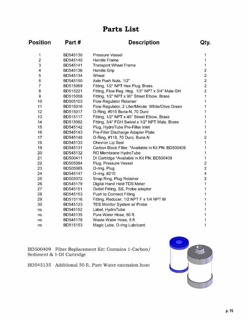
1. Replace Carbon/Sediment pre-filter as directed in the Maintenance section of this manual on page 13.2. Lay HydroTube® down horizontally on a hard surface.3. Remove Snap Ring on the inlet end by the wheels. If snap ring is tight, push plug down (in) to release pressure on snap ring. It should come out easily.4. Remove Plug. Rock plug back and forth if needed to unseat from o-ring.5. Remove used filter and discard into the trash.6. Open new filter package.7. Remove the 2 rubber gaskets from the ends of the new filter and discard.8. Apply a thin film of Magic Lube to the inside diameter of both ends of the new filter.
9. Install filter onto Tube Adaptor inside HydroTube®.10. Make sure Plug Adaptor is inserted into Plug.11. Apply a thin film of Magic Lube on to the large Plug o-ring.12. Insert Plug o-ring into place in HydroTube® housing.13. Install Plug. Make sure it is fully seated down over the o-ring.14. Install snap Ring tail end first. It is very important to ensure the snap ring is seated all the way into its groove.
Tube AdaptorCarbon/Sediment Filter
Plug AdaptorSnap Ring
Plug
Plug O-Ring
Apply Magic Lube

1. p. 8
DI Resin Cartridge Replacement1. Replace DI Resin Cartridge at the same time along with the Carbon/Sediment filter or if TDS levels on the Pure Water exceeds 1% of the feed water TDS level2. Stand HydroTube® up vertically or lay down on a hard surface.3. Remove Snap Ring on the Pure Water outlet end by the handle. If snap ring is tight, push Plug down to release pressure on snap ring. It should come out easily.4. Remove Plug. Rock plug back and forth if needed to unseat from o-ring.5. Remove used cartridge and discard into the trash.6. Remove foil tape from the ends of the new cartridge.
7. Apply a thin film of Magic Lube to the outside diameter of the male end of the new cartridge.8. Install cartridge, female end down onto the membrane permeate tube inside HydroTube®.9. Apply a thin film of Magic Lube on to the large Plug o-ring. 10. Insert Plug o-ring into place in HydroTube® housing.11. Install Plug. Make sure it is fully seated down over the o-ring.12. Install snap Ring tail end first. It is very important to ensure the snap ring is seated all the way into its groove
Plug O-Ring
DI Resin Cartridge
Apply Magic Lube
PlugSnap Ring

1. p. 9
Eco-Boost ModuleThe Eco Boost module is an electrically driven centrifugal pump which will increase the feed water pressure to the HydroTube® system by 50 psi. This will increase the Pure Water volume by 60-100%, depending on supply water pressure and temperature. Example: Your tap water supply pressure is 40 psi, when the pump is turned on, the pressure to the RO membrane will be 90 psi. It will also increase the Pure Water pressure to the brush allowing cleaning with the longest poles available.
Operational note: With the Eco-Boost module installed and the pump motor turned OFF, the Hydrotube® will perform as a non-powered unit. The pump will not interfere with the water flow or pressure from the supply tap.
Installation1. Lay HydroTube® down horizontally on a hard surface.2. Place Eco-Boost module onto HydroTube® with the connections facing the wheel end. The end of thecurved frame should contact the black end cap on the HydroTube® .3. Remove nut from band clamp.
4. Spread clamp open and place around tube and module frame on the motor end.5. Squeeze clamp ends together while guiding the bolt into the clamp end.6. Attach nut finger tight.7. Repeat steps 3-6 for the pump end.8. Center module on top and tighten clamp nuts

1. p. 10
SetupSetup Connections
1. Locate supply water connection at job site.2. Find suitable setup location for Hydrotube® at the job site.3. Lay HydroTube® down in a horizontal position for maximum stability.
4. Connect a 5/8 inch ID or larger garden hose to the supply water connection fitting. Use of more than 100 ft of garden hose may affect system performance.5. Connect the male end of the garden hose to the INLET port on the Eco-Boost pump.6. Position the WASTEWATER hose outlet to landscape or other area to accept the concentrate water flow. Additional garden hoses may be added if required to reach designated area.7. Connect the PURE WATER hose to the fitting on the end by the handle, in the center of the cap.8. Connect the other end of the PURE WATER hose to the water-fed pole hose. A control valve is typically installed between these two hoses for operator control. Open the control valve fully.
WARNING! Hazardous Voltage. Risk of dangerous or fatal electric shock. Plug the pump into a 115 Volt, 60 cycle, ground fault circuit interrupter (GFCI) protected grounded outlet only. This pump is equipped with a 3-wire, grounded, cord and GFCI plug. Make sure the pump circuit meets the National Electrical Code in the USA or the Canadian Electrical Code in Canada. To Avoid dangerous electrical shock hazard, keep the cord dry at all times.
9. Plug GFCI plug into a properly grounded circuit. If an extension cord is required, use this table to size the extension cord.10. Press the TEST button on the GFCI. The light should go out and you will hear a click. This indicates the GFCI is operational.11. Press the RESET button on the GFCI. The green light will illuminate and you will hear a click. The unit is ready for operation.
Supply Water Inlet
Wastewater OutletPure Water out to Pole
TestReset
Indicator Light
Cord Length0-150 Ft151-200 Ft201-350 Ft
Cord Wire Size14 AWG12 AWG10 AWG

1. p. 11
Operation1. Turn water supply valve to its full open position.2. Turn pump power switch to the ON position.3. Verify water flow at the WASTEWATER outlet.4. Open PURE WATER at pole.5. Allow PURE WATER to flow from brush for 1 – 2 minutes.6. Take a sample of the PURE WATER at the brush and test it with the TDS meter. If water test is higher than 10 ppm, service of HydroTube® is required.7. Wash windows as directed. Adhere to safety precautions for use as recommended by pole manufacturer.
Shutdown
1. Open PURE WATER valve at pole if installed.2. Turn pump power switch to the OFF position.3. Turn water supply valve to its fully closed position.4. Unplug GFCI power cord .5. Disconnect water supply hose from HydroTube®.6. Disconnect PURE WATER hose from HydroTube®.7. Disconnect additional hose that may have been attached to the WASTEWATER hose. Do not disconnect the WASTEWATER hose.8. Stand HydroTube up vertically on a flat, hard surface.9. Allow water to drain from HydroTube® for 3-5 minutes. This will allow the high TDS concentrate water to drain out of the unit, extending the overall life of the RO membrane.10. Connect the male end of the waste water hose to the INLET port on the boost pump. This will keep the unit sealed up so residual water will not drain out during transportation.
Power Switch
Warning! Pump has an autoreset thermal overload protector. If the motor overheats, the overload will cut off the power to prevent damage and will reset after the motor cools. If the overload trips repeatedly, check the pump for the cause.

1. p. 12
Eco-Boost PumpExploded View
1
2
8
44
7
3
6
5
Item Part Number Description Qty1 BD545165 Pump Motor Asm 12 BD545166 GFCI W/35FT Cord 13 BD545164 Frame Assembly 14 BD545167 Band Clamp 25 BD545182 Adaptor Fitting 26 (Not Shown) BD545187 Gasket for Adaptor Ftg. 27 BD545169 Coupler, 3/4 GH 18 BD545168 Discharge Hose 1
Parts List
Electrical Specifications115 volts AC, 6 amp, 60 Hz, Single phase
BD545219

1. p. 13
MaintenanceTracking the usage of the HydroTube is critical as it provides the information for replacement of the Carbon /Sediment filter. The DI cartridge should be replaced at the same time. Supply water pressure and temperature will affect the production rate (output flow) of Pure Water. Periodically measure this flow rate and use the table below as a guide to indicate when you need to replace the cartridges.
TroubleshootingLow supply water flow or pressure:1. Eliminate all extension hoses and connect directly to spigot with a single hose.2. Check for blockage or kinks in hose.3. Connect to different water source.4. Replace carbon/sediment filter.______________________________________________________________________High wastewater flow with low Pure Water flow and Good supply pressure:1. Check waste water flow rate. If more than 0,6 gpm, replace flow regulator2. Extremely cold water supply. Measure temperature.3. Plugged membrane – Replace membrane______________________________________________________________________High pure water TDS and/or high pure water flow rate:1. Damaged membrane – replace membrane2. Membrane installed upside down______________________________________________________________________Pump motor does not start:1. Test and reset GFCI. Green light should be illuminated.2. Ensure receptacle is energized.3. Check motor temperature, if hot, allow to cool and restart.4. Check extension cords.
Gallons/Minute Ounces/Minute Total Hours0.4 51 43.90.5 64 39.70.6 77 36.20.7 90 33.30.8 102 30.90.9 115 28.71.0 128 26.91.1 141 25.31.2 154 23.81.3 166 22.51.4 179 21.41.5 192 20.3
Pure Water Flow Rate Change Filters @ Flow Test Procedure1. Locate a container that willhold 1/2 to 1 gallon. One with volumegraduations is preferred or use ameasuring cup to measure watercollected.2. Using a stop watch of timer,direct water flow into the containerfor up to 1 minute.3. Calculate volume of water bythe collection time.
Example: Mike collected 36 oz ofpure water in 15 seconds.36 oz X 4 = 144 oz/minute.144 oz ÷128 oz/gal = 1.13 gal/min

1. p. 14
1. p. 15

1. p. 16
IPC Eagle Warranty PolicyLimited WarrantyIPC Eagle warrants new cleaning equipment against defects in material and workmanship under normal use and service to the original purchaser as detailed below.
1 yearSubject to the conditions stated below, IPC Eagle warrants all other cleaning equipment components to be free from defects in materials and workmanship for a 1-year period. Parts replaced or repaired are warranted for the remainder of the original warranty period. Batteries are pro-rated for one year.
IPC Eagle will furnish and charge for replacement parts, including transportation, to the original owner through an IPC Eagle authorized service center. If the part is returned within 30 days and is found defective, the owner will be credited for the cost of the replacement part including shipping and handling.
Wear items exempt from warranty include hoses, fittings, valves, filters and membranes.
This warranty shall not apply to failures caused by misuse or abuse, improper maintenance as stated in the operation manuals, use of unauthorized repair parts, repairs by other than an IPC Eagle authorized service center, and damage in transit.
IPC Eagle disclaims and denies any liability for any direct, indirect, special incidental or consequential damage which may be suffered as a result of sale, delivery, servicing, use, loss of any product, downtime, labor, freight, or other charges not expressly included herein.
Serial Number______________________________
Purchase Date______________________________
Purchased From:____________________________
IPC Eagle Corporation3650 Dodd Rd, Eagan, MN 55123651.686.5399 • Fax 651.686.5695 • 800.486.2775www.ipceagle.com
© Copyright IPC Eagle 2012 Rev D 5/12