operations manual - justflight.comcdn.justflight.com/support/146-200300...
TRANSCRIPT

www.justflight.com
2 Stonehill, Stukeley Meadows, Huntingdon, PE29 6ED, United Kingdom OPERATIONS MANUAL

www.justflight.com
2 Stonehill, Stukeley Meadows, Huntingdon, PE29 6ED, United Kingdom OPERATIONS MANUAL
1
CONTENTSINTRODUCTION.......................................................................................................2INSTALLATION .........................................................................................................3PANELS ....................................................................................................................5
Main panels .....................................................................................................5Overhead panel ...............................................................................................8Pedestal .........................................................................................................18Glareshield.....................................................................................................21Panel Selector Icons ....................................................................................23Autopilot ........................................................................................................24Panel configurations ....................................................................................26Auto start .......................................................................................................26Doors and Ground Power Unit ....................................................................26Weather radar ...............................................................................................27
MODEL CONFIGURATIONS ..................................................................................28FAQs .......................................................................................................................28TUTORIAL – FLYING THE 146-200 .......................................................................30CHECKLISTS ..........................................................................................................53CREDITS .................................................................................................................57COPYRIGHTS .........................................................................................................57SOFTWARE PIRACY ..............................................................................................58
146-200/300 Jetliner
OPERATIONS MANUAL
Please note that Flight Simulator X must be installed correctly on your PC prior to installation and use of 146-200/300 Jetliner.
2
INTRODUCTIONThe prototype of the BAe 146 short haul jet airliner first flew in 1981. While the standard 146-100 has 93 passenger seats, the aircraft modelled in this simulation – the 146-200 – has 109 seats in a longer fuselage. Some 115 146-200 aircraft were built and in 1990 the line was relaunched as the Avro RJ series.
The 146 series of aircraft are renowned for their relatively quiet operation, which proved ideal for coping with the stringent noise limits around city centre airports. The 146 is widely used by European airlines and can be used on flights to London City airport with its short runway and steep approach.
The 146 has a royal connection, being the first jet aircraft to be operated by the British Queen’s Flight, later to become 32 (The Royal) Squadron. Needless to say, the Queen’s aircraft were fitted out with luxury interiors, and operated with a capacity of 19 passengers and a crew of six.
This package also includes the 146-300 with five international airline liveries. Developed in the late 1980s, the 146-300 is a stretched derivative of the 146-200 designed for airlines that required greater passenger capacity. The 146-300 has an extended fuselage (2.44m longer than that found on the 146-200) providing space for a further 15 passenger seats.
We hope you’ll enjoy this 146-200/300 package for FSX – we’ve included a tutorial flight from Brussels to Manchester to help you get the most from this amazing aircraft.
146-200 Jetliner aircraft specificationsDimensionsLength 28.60mWingspan 26.21mHeight (to top of fin) 8.59mWing area 77.30m2
PowerplantsType 4 x Textron Lycoming ALF 502R-5 turbofans
Static thrust 6,970 lbs per engine
WeightsMaximum take-off 42,184 kg
Maximum landing weight 36,74 kg
Empty weight 23,897 kg
PerformanceVMO 350 knots / 0.72 Mach
Service ceiling 31,000 ft
Range (max. payload) 1,200 nautical miles
Crew Usually two plus cabin staff
Passengers 109 seat capacity
3
INSTALLATIONYou’ve already purchased the Download and have got this far by following the instructions on our website. However, here are some FAQs that might be helpful.
How do I install and unlock the software once I have paid for it?
Full instructions will appear on screen once you have bought a download add-on. These will also be sent to you in an email for future reference.
How will I know the product has unlocked correctly?
A message will appear on screen telling you that the unlocking process has been completed (and how to contact us in the unlikely event that you experience any problems). Please read all instructions and emails carefully.
What happens if I change my PC or need to reinstall the software?
If you change your computer system or your licence files are ‘broken’ (perhaps due to a re-installation of Windows or a hard drive malfunction) you will need to unlock the software again.
Once you have unlocked the product you can install it as often as you like on the same computer system.
Accessing the aircraftTo access the 146-200/300 variants in FSX:
1. Click on Free Flight
2. Select ‘Just Flight’ from the ‘Publisher’ drop-down menu
3. Select ‘British Aerospace’ from the Manufacturer drop-down and choose one of the 146 variants.
Tick the ‘Show all variations’ box to see all the available airline liveries.
UninstallingTo uninstall this software from your PC:
• GototheWindowsStartmenuandselect‘ControlPanel`(ifyouareinWindowsClassic view, Control Panel will be found under ‘Settings’).
• Double-clickontheitem‘AddorRemovePrograms’(WindowsXP)or‘ProgramsandFeatures’ (Windows Vista or 7).
• Selecttheprogramyouwanttouninstallfromthelistprovidedandclickthe ‘Uninstall’ option.
Uninstalling or deleting this software in any other way may cause problems when using this program in the future or with your Windows set-up.

4
Website Updates Please check the News and Support pages on our website at justflight.com for news and updates for this and all our other products.
Technical SupportTo obtain technical support (in English) please visit the Support pages at justflight.com. As a Just Flight customer you can obtain free technical support for any Just Flight or Just Trains product.
If you don’t have Internet access, please write to us at Just Flight Technical Support, 2 Stonehill, Stukeley Meadows, Huntingdon, PE29 6ED, UK.
Regular NewsTo get the latest news about Just Flight products, sign up for our newsletter at justflight.com/newsletter.

5
PANELSMain panels
1. AFGSannunciator
2. Clock test button
3. Airspeed/Mach indicator
4. Digital clock/chronometer
5. Dual-needle radio magnetic indicator (RMI)
6. Attitude Indicator (AI)
7. Horizontal Situation Indicator (HSI)
8. Altimeter
9. Radio altimeter/decision height selector and alert (decision height can be set manually)
10. Vertical speed indicator (VSI)
11. Brake pressure indicators (yellow and green hydraulic systems)
12. Standby altimeter
13. Standby attitude indicator
14. AFGSannunciator
15. Transponder switch

6
1. Engine oil quantity, temperature and pressure gauges
2. N1 gauges – low pressure compressor/turbine speed
3. TGTgauges–engineexhaustgastemperaturegauge
4. N2 gauges – high pressure compressor/turbine speed
5. Fuel flow gauges
6. Fuel quantity gauges
7. Fuel quantity electric feed button
8. Master warning system annunciator
9. Flap position indicator
10. Engine vibration gauges
11. Engine vibration gauge test button
12. Undercarriage lever
13. Spoiler and undercarriage position indicators
7
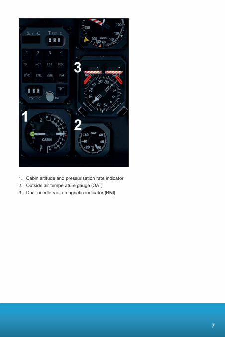
1. Cabin altitude and pressurisation rate indicator
2. Outside air temperature gauge (OAT)
3. Dual-needle radio magnetic indicator (RMI)
8
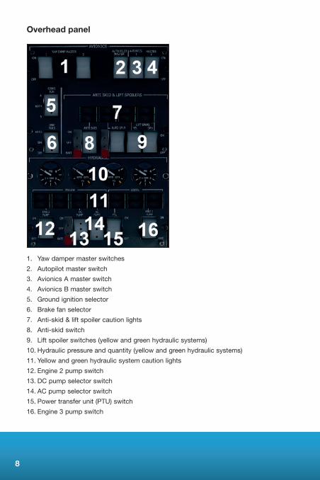
Overhead panel
1. Yaw damper master switches
2. Autopilot master switch
3. Avionics A master switch
4. Avionics B master switch
5. Groundignitionselector
6. Brake fan selector
7. Anti-skid & lift spoiler caution lights
8. Anti-skid switch
9. Lift spoiler switches (yellow and green hydraulic systems)
10. Hydraulic pressure and quantity (yellow and green hydraulic systems)
11. Yellow and green hydraulic system caution lights
12. Engine 2 pump switch
13. DC pump selector switch
14. AC pump selector switch
15. Power transfer unit (PTU) switch
16. Engine 3 pump switch

9
1. Fuel tank quantity gauges
2. Fuel system caution lights
3. Fuel temperature gauge
4. Tank selector mode switch
5. Cross-feed switch
6. Left fuel standby pump switch
7. Left common feed switch
8. Right common feed switch
9. Right fuel standby pump switch
10. Fuel pump caution lights
11. Engine fuel pump switches
10
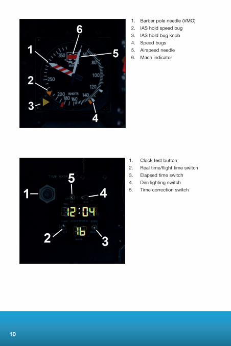
1. Barber pole needle (VMO)
2. IAS hold speed bug
3. IAS hold bug knob
4. Speed bugs
5. Airspeed needle
6. Mach indicator
1. Clock test button
2. Real time/flight time switch
3. Elapsed time switch
4. Dim lighting switch
5. Time correction switch

11
1. DME read-out
2. VOR/GPSflag
3. Course deviation indicator (CDI)
4. Glideslopeindicator
5. Groundspeedread-out
6. Heading bug
1. DME 1 read-out
2. VOR/ADF 1 switch
3. VOR/ADF 2 switch
4. VOR/ADF 1 needle
5. VOR/ADF 2 needle
6. DME 2 read-out

12
1. Speed deviation scale
2. Instrument failure flag
3. Aircraft symbol
4. Test button
5. Slip indicator
6. Localiser position indicator
7. Glideslopepositionindicator
8. Glideslopeindicationfailureflag
9. Localiser indication failure flag

13
1. Generator1switch
2. Galley/Shedswitch
3. APU generator switch
4. Generator4switch
5. Generatorcautionlights
6. Generatorcurrentgauges
7. External AC Master switch
8. AC/DC bus-tie switches
9. Standby inverter master switch
10. Standby generator master switch
11. Electrical system caution lights
12. AC amps gauge (source is selected using AC selector knob)
13. AC selector knob
14. Hertz (Hz) gauge
15. DC volts gauge (source is selected using DC selector knob)
16. DC selector knob
17. Battery master switches
18. Transformer rectifier 1 and 2 current gauges (amps)
19. Battery current gauge
14
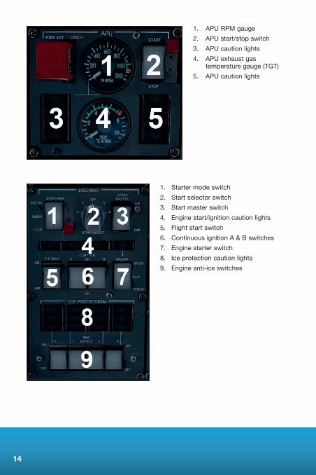
1. APU RPM gauge
2. APU start/stop switch
3. APU caution lights
4. APU exhaust gas temperaturegauge(TGT)
5. APU caution lights
1. Starter mode switch
2. Start selector switch
3. Start master switch
4. Engine start/ignition caution lights
5. Flight start switch
6. Continuous ignition A & B switches
7. Engine starter switch
8. Ice protection caution lights
9. Engine anti-ice switches

15
1. Discharge valve selector knob
2. Discharge valve 1 & 2 position indicators
3. Manual pressure rate knob
4. Pressurisation auto/manual button
5. Cabin and flight altitude gauge
6. Auto-pressurisation rate knob
7. Cabin altitude knob
1. Heater caution lights
2. Screen heat switches
3. Auxiliary and left vane heat switch
4. Pitot heat and right vane heat switches
5. Anti-ice valve caution lights
6. Outer wing anti-ice switch
7. Inner wing anti-ice switch
8. Tail anti-ice switch
16
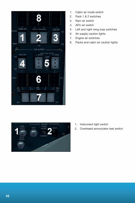
1. Cabin air mode switch
2. Pack 1 & 2 switches
3. Ram air switch
4. APU air switch
5. Left and right wing loop switches
6. Air supply caution lights
7. Engine air switches
8. Packs and cabin air caution lights
1. Instrument light switch
2. Overheard annunciator test switch

17
1. Groundtestswitches
2. Panel flood light switch
3. Wing lights switch
4. Logo light switch
5. No Smoking notice switch
6. Cabin emergency notice switch
7. Rotating beacon light switch
8. Strobe light switch
9. Navigation light switch
10. Flight deck automatic/manual temperature control switch
11. Flight deck duct temperature select switch
12. Flight deck fan switch
13. Cabin fan switch
14. Cabin duct temperature select switch
15. Cabin automatic/manual temperature control switch
16. Flight deck automatic temperature selector
17. Flight deck duct and cabin temperature gauges
18. Cabin duct temperature gauge
19. Cabin automatic temperature selector
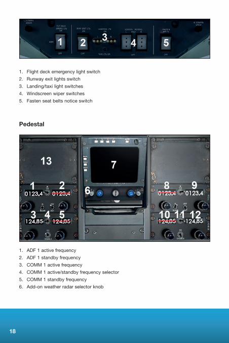
18
1. Flight deck emergency light switch
2. Runway exit lights switch
3. Landing/taxi light switches
4. Windscreen wiper switches
5. Fasten seat belts notice switch
Pedestal
1. ADF 1 active frequency
2. ADF 1 standby frequency
3. COMM 1 active frequency
4. COMM 1 active/standby frequency selector
5. COMM 1 standby frequency
6. Add-on weather radar selector knob

19
7. Add-on weather radar (if applicable – refer to separate PDF manual)
8. ADF 2 active frequency
9. ADF 2 standby frequency
10. COMM 2 active frequency
11. COMM 2 active/standby frequency selector
12. COMM 2 standby frequency
13.GPSclick-spot
1. Speed brake lever
2. Engine throttle levers (fuel can be cut off by clicking on the base of each throttle lever when they are placed in the idle position)
3. Flap lever
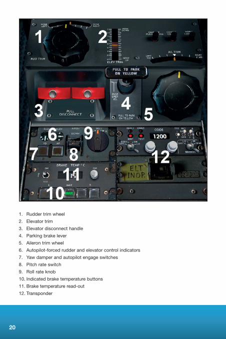
20
1. Rudder trim wheel
2. Elevator trim
3. Elevator disconnect handle
4. Parking brake lever
5. Aileron trim wheel
6. Autopilot-forced rudder and elevator control indicators
7. Yaw damper and autopilot engage switches
8. Pitch rate switch
9. Roll rate knob
10. Indicated brake temperature buttons
11. Brake temperature read-out
12. Transponder
21
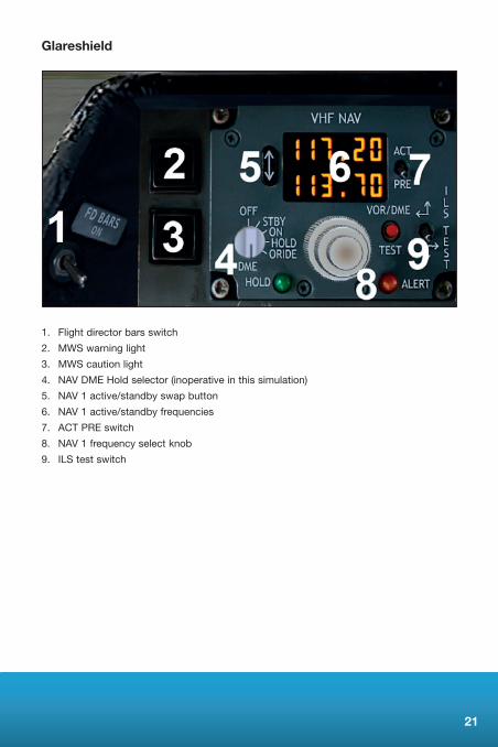
Glareshield
1. Flight director bars switch
2. MWS warning light
3. MWS caution light
4. NAV DME Hold selector (inoperative in this simulation)
5. NAV 1 active/standby swap button
6. NAV 1 active/standby frequencies
7. ACT PRE switch
8. NAV 1 frequency select knob
9. ILS test switch

22
1. Approach hold button
2. Altitude hold button
3. Vertical speed hold button
4. Mach hold button
5. VNAV button (inoperative in this simulation)
6. IAS hold button
7. Nav hold button
8. Back course hold button
9. Wing leveller button
10.LNAVGPSbutton(autopilotwillholdtheGPSflightplan)
11. Heading hold button
12. Autopilot master button
13. NAV 1 course knob
14. NAV 2 course knob
15. Heading bug knob
16. NAV 1 course value
17. NAV 2 course value
18. HSI NAV select split knob
1. ALT ARM (altitude arm) button
2. ALT SEL (altitude select) window
3. Altitude select wheel
23
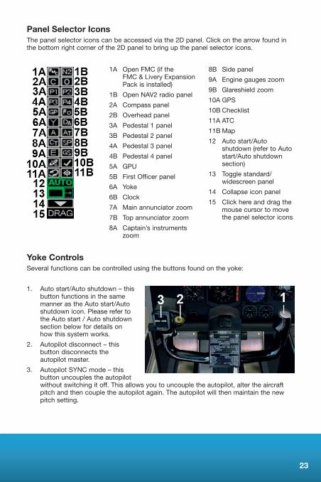
Yoke ControlsSeveral functions can be controlled using the buttons found on the yoke:
1. Auto start/Auto shutdown – this button functions in the same manner as the Auto start/Auto shutdown icon. Please refer to the Auto start / Auto shutdown section below for details on how this system works.
2. Autopilot disconnect – this button disconnects the autopilot master.
3. Autopilot SYNC mode – this button uncouples the autopilot without switching it off. This allows you to uncouple the autopilot, alter the aircraft pitch and then couple the autopilot again. The autopilot will then maintain the new pitch setting.
Panel Selector IconsThe panel selector icons can be accessed via the 2D panel. Click on the arrow found in the bottom right corner of the 2D panel to bring up the panel selector icons.
1A Open FMC (if the FMC & Livery Expansion Pack is installed)
1B Open NAV2 radio panel
2A Compass panel
2B Overhead panel
3A Pedestal 1 panel
3B Pedestal 2 panel
4A Pedestal 3 panel
4B Pedestal 4 panel
5A GPU
5B First Officer panel
6A Yoke
6B Clock
7A Main annunciator zoom
7B Top annunciator zoom
8A Captain’s instruments zoom
8B Side panel
9A Engine gauges zoom
9B Glareshieldzoom
10AGPS
10B Checklist
11A ATC
11B Map
12 Auto start/Auto shutdown (refer to Auto start/Auto shutdown section)
13 Toggle standard/widescreen panel
14 Collapse icon panel
15 Click here and drag the mouse cursor to move the panel selector icons

24
AutopilotThe autopilot on the 146 differs from those found on the more common Boeing and Airbus airliners. In order to control the autopilot, attention will need to be paid to three areas of the cockpit.
Before the autopilot can be used, the Autopilot Master switches on the AVIONICS portion of the overhead panel need to be moved to the ON position.
The autopilot can now be engaged by pressing the AP button on the pedestal.
The AP button located on the glareshield will illuminate, indicating that the autopilot is engaged.
• GSL – Engages approach hold mode, allowing you to capture and hold the glideslope when carrying out an ILS approach
• ALT – Engages altitude hold mode. When pressed, the current altitude will be held by the autopilot. If ALT ARM has been used, the ALT button will illuminate once the aircraft has reached the altitude shown in the ALT SEL window to indicate that the aircraft is maintaining the selected altitude
• VS – Engages vertical speed hold mode. When pressed, the current vertical speed will be held
• V NAV – This button is inoperative in this simulation

25
• IAS – Engages indicated airspeed hold mode. The aircraft will either climb or descend to hold the airspeed that the aircraft was maintaining when the button was pressed. This should not be confused with the auto-throttle or VNAV systems on board modern airliners. The autopilot will not alter the throttle position; it will simply alter the aircraft pitch to maintain the current airspeed at the current throttle position. For this reason you must monitor both your airspeed and throttle position when using this autopilot mode
• V/L – Engages VOR LOC / NAV hold mode. When pressed, the aircraft will alter the aircraft heading to intercept a VOR radial or the localiser for an ILS approach
• B LOC – Engages back-course hold mode for use on ILS approaches
• TURB – Engages turbulence mode, softening autopilot-controlled movements. OnlyHDGmodecanbeengagedwhenTURBmodeisactive
• L NAV–EngagesGPSholdmode.Whenpressed,theautopilotwillsteertheaircrafttomaintaintherouteprogrammedintotheGPS
• HDG – Engages heading hold mode. When pressed, the autopilot will steer the aircrafttomaintaintheheadingselectedusingtheHDGcontrolknob
• ALT ARM – Engages altitude arm mode. When pressed, and with either IAS or VS mode engaged, the autopilot will climb or descend to the altitude shown in the ALT SEL window before levelling out
The autopilot can be disconnected by clicking on the AP button on the pedestal, pressing the [Z] key or by clicking on the autopilot disconnect button found on the yoke in the virtual cockpit.
26
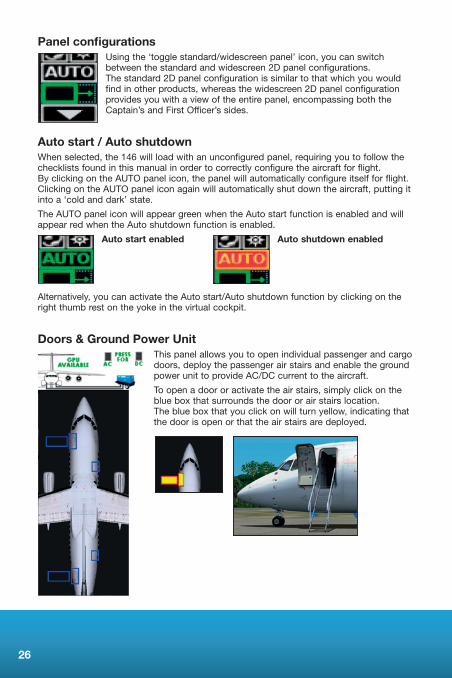
Panel configurationsUsing the ‘toggle standard/widescreen panel’ icon, you can switch between the standard and widescreen 2D panel configurations. The standard 2D panel configuration is similar to that which you would find in other products, whereas the widescreen 2D panel configuration provides you with a view of the entire panel, encompassing both the Captain’s and First Officer’s sides.
Auto start / Auto shutdown When selected, the 146 will load with an unconfigured panel, requiring you to follow the checklists found in this manual in order to correctly configure the aircraft for flight. By clicking on the AUTO panel icon, the panel will automatically configure itself for flight. Clicking on the AUTO panel icon again will automatically shut down the aircraft, putting it into a ‘cold and dark’ state.
The AUTO panel icon will appear green when the Auto start function is enabled and will appear red when the Auto shutdown function is enabled.
Auto start enabled Auto shutdown enabled
Alternatively, you can activate the Auto start/Auto shutdown function by clicking on the right thumb rest on the yoke in the virtual cockpit.
Doors & Ground Power Unit This panel allows you to open individual passenger and cargo doors, deploy the passenger air stairs and enable the ground power unit to provide AC/DC current to the aircraft.
To open a door or activate the air stairs, simply click on the blue box that surrounds the door or air stairs location. The blue box that you click on will turn yellow, indicating that the door is open or that the air stairs are deployed.
27
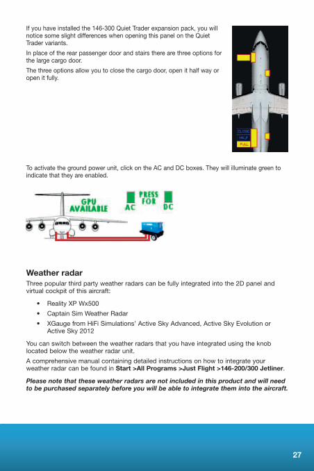
If you have installed the 146-300 Quiet Trader expansion pack, you will notice some slight differences when opening this panel on the Quiet Trader variants.
In place of the rear passenger door and stairs there are three options for the large cargo door.
The three options allow you to close the cargo door, open it half way or open it fully.
To activate the ground power unit, click on the AC and DC boxes. They will illuminate green to indicate that they are enabled.
Weather radarThree popular third party weather radars can be fully integrated into the 2D panel and virtual cockpit of this aircraft:
• RealityXPWx500
• CaptainSimWeatherRadar
• XGaugefromHiFiSimulations’ActiveSkyAdvanced,ActiveSkyEvolutionorActive Sky 2012
You can switch between the weather radars that you have integrated using the knob located below the weather radar unit.
A comprehensive manual containing detailed instructions on how to integrate your weather radar can be found in Start >All Programs >Just Flight >146-200/300 Jetliner.
Please note that these weather radars are not included in this product and will need to be purchased separately before you will be able to integrate them into the aircraft.

28
MODEL CONFIGURATIONSThe 146 was in service with several window and air stair configurations. Tools have been included with this aircraft so you can select which of these configurations you would like to use for each of the liveries.
The tools can be found in Start >All Programs>Just Flight>146-200/300 Jetliner. There are tools for the 146-200, 146-300 and also the 146-300QT model if you have bought this additional model.
Follow the on-screen instructions to select one of the following configurations:• Allpassengerwindowsvisible–noairstairsfitted
• Firstleftpassengerwindowfittedwithblankingplate–frontairstairsfitted
• Firstleftandrightpassengerwindowsfittedwithblankingplates–frontair stairs fitted
• Firstleftandright,andlastleftpassengerwindowsfittedwithblankingplates–front and rear air stairs fitted
• Firstleftandright,andlastleftandrightpassengerwindowsfittedwithblankingplates – front and rear air stairs fitted
If you have the FMC/Livery Expansion Pack installed, you can choose between FMC andGPSnavigationmethodsbyusingthetoolforthe146-200.Selectionsviathistoolwill govern the navigation method for the -200, -300 and 146-300QT (if purchased and installed) models.
FAQSHow do I open the doors and extend the air stairs?Youcanopenthepassengerandcargodoors,andextendtheairstairs,usingtheGPUpop-uppanel.Pleaserefertothe‘Doors&GroundPowerUnit’sectionofthemanualfordetailed instructions.
Why is the elevator position fixed while on the ground?The elevator will have a fixed deflection when below 50 knots. As you accelerate to speeds above 50 knots, the elevator will return to the normal position.
Why can I not move the ailerons or flaps?Please ensure you have configured the aircraft correctly, making use of the checklists or tutorial flight. If the hydraulic systems are not correctly configured, the ailerons and flaps will not function.
The instruments are not working when I load the aircraftThe cockpit needs to be configured either by following the checklists, tutorial flight or alternatively by using the Auto Start icon.
How do I get the weather radar to work?The aircraft does not feature its own weather radar, but the Reality XP, Captain Sim or HiFi Simulations units can be fully integrated into the virtual cockpit. Please refer to the separate weather radar PDF manual for detailed instructions on how to set up your chosen weather radar.
29
How do I switch on TCAS?
To switch on TCAS, click on the switch found on the top right corner of the vertical speed indicator gauge.
How do I operate the fuel valves on the throttle levers?
Move the throttle lever to the idle position and then right-click on the base of the lever to open or close the fuel valve.
How do I engage the autopilot?
To engage the autopilot, the autopilot master switch on the overhead panel needs to be switched on. You then need to press the AP button found on the pedestal to engage the autopilot. Please refer to the ‘Autopilot’ section of the manual for more instructions on configuring the autopilot.
How do I use the multi-position rocker switches?
The multi-position rocker switches, for example the BRK FANS switch, have three positions denoted by three black spots. Left click on the upper, middle or lower portion of the switch to select one of the positions.
How do I access the virtual cabin?
You can access the virtual cabin either by using the FSX viewpoint movement keys, a third party tool such as Walk & Follow or by selecting one of the cabin viewpoint presets found under the ‘Virtual Cockpit’ view category.
How does the cockpit night lighting function?
There are four cockpit lighting switches:
• PANELFLOOD–inthetoprightcorneroftheoverheadpanel.Thisswitchturnson the flood lighting for the main panel area
• DIMGLARESHIELD–inthebottomleftcorneroftheoverheadpanel.Thisswitchturns on the panel backlighting
• DIMINSTS–inthebottomrightcorneroftheoverheadpanel.Thisswitchturnson the gauge backlighting
• DIMPANEL–inthebottomrightcorneroftheoverhead.Thisswitchturnsonthecockpit flood lighting
Why does an ENG OVSPD (engine overspeed) caution appear on the MWS when I advance the throttle levers?
AnENGOVSPDcautionwillappearontheMWSiftheN1risesabove100%.AdjustthethrottleleverpositionstoreduceN1tobelow100%.
Why do the lights not turn on when pressing the [L] key?
Due to the complexity of the lighting system, it makes use of custom coding and therefore the keyboard shortcut cannot be used. Please use the lighting switches found on the overhead panel.

30
TUTORIAL – FLYING THE 146-200 (BRUSSELS TO MANCHESTER)
For today’s tutorial flight we will be departing from Brussels National airport, to the north-east of the city, in the colours of Brussels Airlines. We will be heading north-west, leaving the coast of Belgium close to Ostend, before entering UK airspace to the east of London. We will then turn further north, heading first for East Midlands airport before continuing to Manchester. Covering a distance of approximately 300 nautical miles, this route is the ideal length for learning about the various systems on board the 146.
Here are the details for today’s flight:
Flight planEBBR-LERVO-KERKY-DENUT-LUMEN-BULAM-DIBLI-RAPIX-TEBRA-KOPUL-GILDA-FERIT-WESUL-STOAT-MOGLI-LESTA-SKINA-NANTI-TABLY-EGCC
Estimated time en-route: One hour (subject to weather)
Route distance: 329 nautical miles
Departure time: 11:30 (local time)
Weather: Clear
31
Now that we are prepared for the flight we can proceed to the cockpit to begin our pre-flight checks. To load up the 146-200 tutorial flight, follow these steps:
1. Start Flight Simulator X
2. Select the Free Flight menu
3. Choose Load from the row of buttons just above the aircraft preview window
4. Select 146 tutorial flight from the list of saved flights
5. Click on Fly Now!
You should now find yourself sitting in the cockpit of a 146-200 located at gate 143 of Brussels National airport. The cockpit is currently in a ‘cold and dark’ state. This term is used to describe a cockpit in which all its systems are switched off, as you would find it prior to the first flight of the day. This means we will need to spend some additional time setting up the cockpit, but doing so with the assistance of this tutorial will allow you to learn a considerable amount about the features and functions on board this classic aircraft.
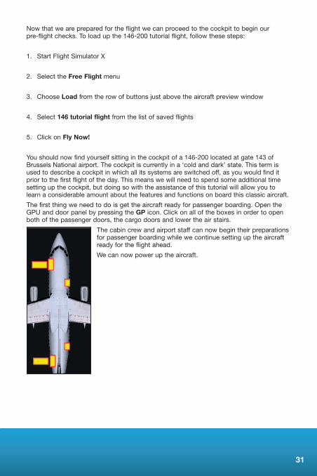
The first thing we need to do is get the aircraft ready for passenger boarding. Open the GPUanddoorpanelbypressingtheGP icon. Click on all of the boxes in order to open both of the passenger doors, the cargo doors and lower the air stairs.
The cabin crew and airport staff can now begin their preparations for passenger boarding while we continue setting up the aircraft ready for the flight ahead.
We can now power up the aircraft.
32
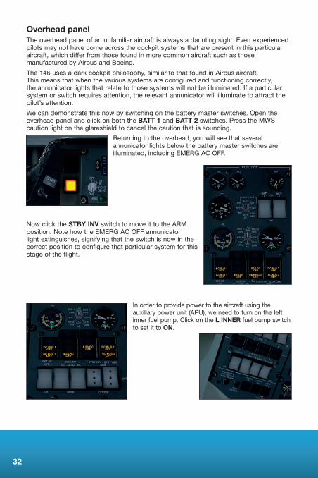
Overhead panelThe overhead panel of an unfamiliar aircraft is always a daunting sight. Even experienced pilots may not have come across the cockpit systems that are present in this particular aircraft, which differ from those found in more common aircraft such as those manufactured by Airbus and Boeing.
The 146 uses a dark cockpit philosophy, similar to that found in Airbus aircraft. This means that when the various systems are configured and functioning correctly, the annunicator lights that relate to those systems will not be illuminated. If a particular system or switch requires attention, the relevant annunicator will illuminate to attract the pilot’s attention.
We can demonstrate this now by switching on the battery master switches. Open the overhead panel and click on both the BATT 1 and BATT 2 switches. Press the MWS caution light on the glareshield to cancel the caution that is sounding.
Returning to the overhead, you will see that several annunicator lights below the battery master switches are illuminated,includingEMERGACOFF.
Now click the STBY INV switch to move it to the ARM position.NotehowtheEMERGACOFFannunicatorlight extinguishes, signifying that the switch is now in the correct position to configure that particular system for this stage of the flight.
In order to provide power to the aircraft using the auxiliary power unit (APU), we need to turn on the left inner fuel pump. Click on the L INNER fuel pump switch to set it to ON.

33
We can now start the APU. Move the APU GEN switch to the ON position and then click on the APU START MASTER switch to start the APU.
TheAPURPMgaugeneedlewillriseandstabiliseatapproximately100%,andtheAPUTGTgaugeshouldreadapproximately500degreesCelsius.Variousannunicatorlightsonthe overhead panel will extinguish and illuminate as the APU begins providing power to the aircraft.
Press the MWS warning and caution lights to cancel the warnings.
Arm the the flight deck and cabin emergency lights.
Set all of the avionics master switches, located in the upper left corner of the overhead panel, to ON in order to provide power to the yaw damper, autopilot and avionics systems.
Click on the upper portion of the ANTI-SKID switch, and the YEL (yellow) and GRN (green) LIFT SPLRS switches to switch those systems on.
34
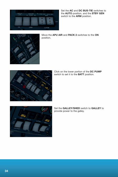
Set the AC and DC BUS-TIE switches to the AUTO position, and the STBY GEN switch to the ARM position.
Move the APU AIR and PACK 2 switches to the ON position.
Click on the lower portion of the DC PUMP switch to set it to the BATT position.
Set the GALLEY/SHED switch to GALLEY to provide power to the galley.
35
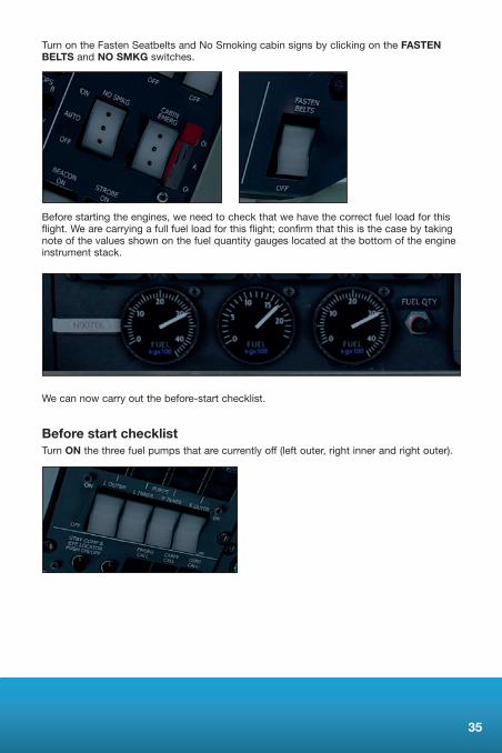
Turn on the Fasten Seatbelts and No Smoking cabin signs by clicking on the FASTEN BELTS and NO SMKG switches.
Before starting the engines, we need to check that we have the correct fuel load for this flight. We are carrying a full fuel load for this flight; confirm that this is the case by taking note of the values shown on the fuel quantity gauges located at the bottom of the engine instrument stack.
We can now carry out the before-start checklist.
Before start checklistTurn ON the three fuel pumps that are currently off (left outer, right inner and right outer).
36
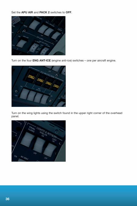
Set the APU AIR and PACK 2 switches to OFF.
Turn on the four ENG ANT-ICE (engine anti-ice) switches – one per aircraft engine.
Turn on the wing lights using the switch found in the upper right corner of the overhead panel.

37
We now need to configure the pressurisation system for the flight. Rotate the Cabin Alt Set knob until the needle points to 8 on the outer scale (for 8,000ft) and rotate the Autopress Rate knob until the tool-tip reads 600 (for 600 feet per minute).
Set the BEACON light switch to ON to alert anyone located near the aircraft that you are about to start the engines.
Before we start the engines, we need to retract the air stairs and close both passenger doors and cargo doors.
Once you have closed all the doors, disengage the parking brakes and then press [Shift]+[P] to begin pushing back the aircraft.
We are now ready to start the engines.

38
Engine startSet the START MASTER switch to ON and move the START SELECT knob to position 4 – corresponding to engine 4.
Now click on the upper portion of the Engine Starter switch to move it into the START position. Engine 4 will start to spool up as indicated by the engine instruments. Monitor the oil pressure reading, and once the N1 and N2 needles have stabilised at approximately24%and55%respectively,youcanmovetheSTART SELECT knob to position 3 and press on the Engine Starter switch to start engine 3.
Repeat this process for engine 2 and then engine 1. Once all engines have been started, cancel the MWS caution by pressing the MWS caution light.
Once the aircraft has been pushed back beyond the central taxi line, press [Shift]+[P] to stop the pushback. Set the parking brakes so that we can carry out the after-start checklist.

39
After start checklistSet the START MASTER switch to OFF and rotate the START SELECT knob to OFF.
Click on the GEN 1 and GEN 4 switches to move them to the ONposition.TheGEN1OFFLINEandGEN4OFFLINEannunciatorlightswillextinguish.
Set the ENG 2 PUMP and ENG 3 PUMP switches to ON. Both LO PRESS annunciator lights will extinguish.
Left-click twice on the upper portion of the BRK FANS (brake fans) switch to set it to AUTO.

40
Set the APU AIR and PACKS 2 switches to ON.
Click on the upper portion of the DC PUMP switch once to set it to OFF.
Switch off the four ENG ANT-ICE switches.
Now switch on the SCREEN HEAT, AUX & L.VANE, PITOT HTRS and R.VANE switches.
All of the ICE PROTECTION annunciator lights will extinguish.
We now need to configure the aircraft for taxiing.

41
TaxiTurn on both TAXI LT switches and the NAV light switch.
For this take-off we will be using 18 degrees of flap, so move the flap lever to the first detent.
Using the flap position gauge, confirm that the flaps have extended to the correct position.
On the pedestal, press the YD (yaw damper) button. The button will illuminate with YD1/YD2 to indicate that the yaw damper is engaged.
42
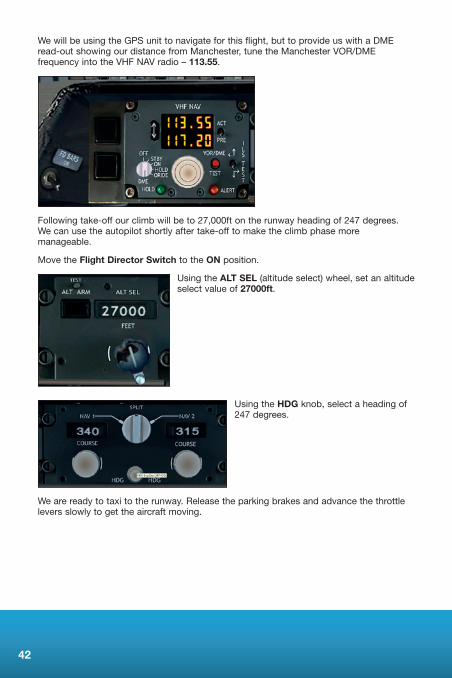
WewillbeusingtheGPSunittonavigateforthisflight,buttoprovideuswithaDMEread-out showing our distance from Manchester, tune the Manchester VOR/DME frequency into the VHF NAV radio – 113.55.
Following take-off our climb will be to 27,000ft on the runway heading of 247 degrees. We can use the autopilot shortly after take-off to make the climb phase more manageable.
Move the Flight Director Switch to the ON position.
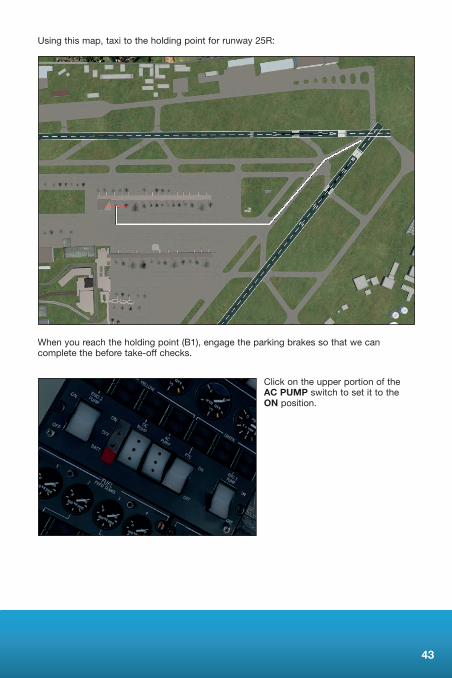
Using the ALT SEL (altitude select) wheel, set an altitude select value of 27000ft.
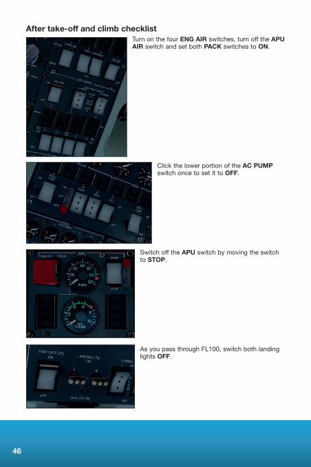
Using the HDG knob, select a heading of 247 degrees.
We are ready to taxi to the runway. Release the parking brakes and advance the throttle levers slowly to get the aircraft moving.
43
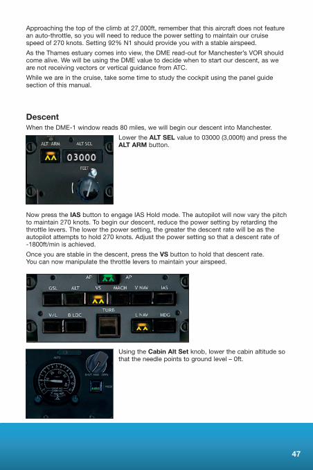
Using this map, taxi to the holding point for runway 25R:
When you reach the holding point (B1), engage the parking brakes so that we can complete the before take-off checks.
Click on the upper portion of the AC PUMP switch to set it to the ON position.

44
Set the LANDING LTS and the STROBE lights to ON.
Release the parking brakes and taxi onto the runway, making sure you turn left to line up on runway 25R.
Bringthethrottleleversforwardtoaround25%,checkthattheenginesarestableusingthe engine instrument gauges and then advance the throttles forward until the N1 needles indicate100%(thetopofthegreenband).
Take-off and climbAs the aircraft starts to gather speed, keep it running down the centre line with small rudder inputs. As you approach 140 knots (Vr), start to raise the nose of the aircraft. Slowly bring the nose up to approximately 10 degrees, rising to 13 degrees as you lift off the runway.
The aircraft will begin to climb away from the runway and you should be well clear of the ground by the time you reach 160 knots. Raise the undercarriage using the G key and alter your pitch to maintain 230 knots, holding a heading of 247 degrees and retracting the flaps as you pass through 2,000ft.
Passing through 2,500ft, engage the autopilot by clicking on the AP (autopilot engage) button.

45
Now press the ALT ARM button followed by the IAS button. The autopilot will now vary the vertical speed in the climb to 27,000ft to hold 230 knots. Do not confuse this with the auto-throttle or VNAV systems on board modern airliners. The autopilot will not alter the throttle position; it will simply alter the aircraft pitch to maintain 230 knots at the current throttle position. For this reason, throughout the climb, you must monitor both your airspeed and throttle position (or N1 engine instruments).
Press the HDG button to engage heading hold mode.
The aircraft should now stabilise in the climb. Retard the throttle levers until the N1 gauges read 95%. This will be our power setting for the climb. At regular intervals during the climb,refertotheN1gaugesandadjustthethrottleleverstoensurethat95%N1isset.
We can now engage navigation hold mode so that the aircraft follows the programmed GPSroute.PresstheL NAVbuttontoengageGPSnavigationholdmode.TheaircraftwillnowturnstarboardtowardstheGPSroute.
Now that the aircraft is settled into the climb, we can go through the after take-off and climb checklist.
46
After take-off and climb checklistTurn on the four ENG AIR switches, turn off the APU AIR switch and set both PACK switches to ON.
Click the lower portion of the AC PUMP switch once to set it to OFF.
Switch off the APU switch by moving the switch to STOP.
As you pass through FL100, switch both landing lights OFF.
47
Approaching the top of the climb at 27,000ft, remember that this aircraft does not feature an auto-throttle, so you will need to reduce the power setting to maintain our cruise speedof270knots.Setting92%N1shouldprovideyouwithastableairspeed.
As the Thames estuary comes into view, the DME read-out for Manchester’s VOR should come alive. We will be using the DME value to decide when to start our descent, as we are not receiving vectors or vertical guidance from ATC.
While we are in the cruise, take some time to study the cockpit using the panel guide section of this manual.
DescentWhen the DME-1 window reads 80 miles, we will begin our descent into Manchester.
Lower the ALT SEL value to 03000 (3,000ft) and press the ALT ARM button.
Now press the IAS button to engage IAS Hold mode. The autopilot will now vary the pitch to maintain 270 knots. To begin our descent, reduce the power setting by retarding the throttle levers. The lower the power setting, the greater the descent rate will be as the autopilot attempts to hold 270 knots. Adjust the power setting so that a descent rate of -1800ft/min is achieved.
Once you are stable in the descent, press the VS button to hold that descent rate. You can now manipulate the throttle levers to maintain your airspeed.
Using the Cabin Alt Set knob, lower the cabin altitude so that the needle points to ground level – 0ft.
48
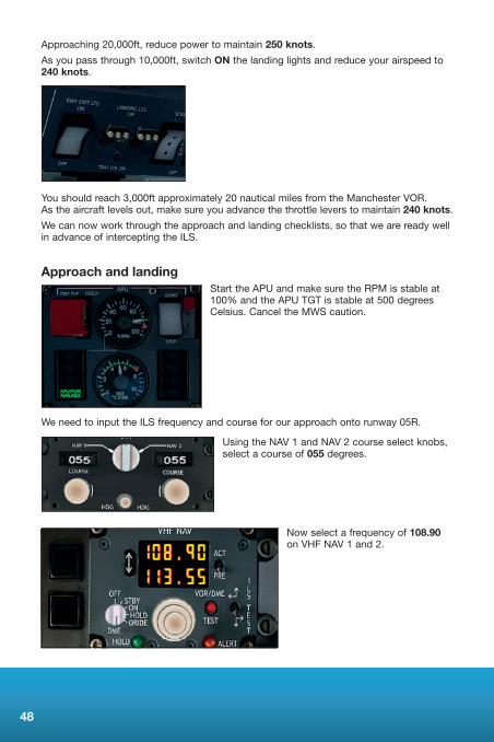
Approaching 20,000ft, reduce power to maintain 250 knots.
As you pass through 10,000ft, switch ON the landing lights and reduce your airspeed to 240 knots.
You should reach 3,000ft approximately 20 nautical miles from the Manchester VOR. As the aircraft levels out, make sure you advance the throttle levers to maintain 240 knots.
We can now work through the approach and landing checklists, so that we are ready well in advance of intercepting the ILS.
Approach and landingStart the APU and make sure the RPM is stable at 100%andtheAPUTGTisstableat500degreesCelsius. Cancel the MWS caution.
We need to input the ILS frequency and course for our approach onto runway 05R.
Using the NAV 1 and NAV 2 course select knobs, select a course of 055 degrees.
Now select a frequency of 108.90 on VHF NAV 1 and 2.
49
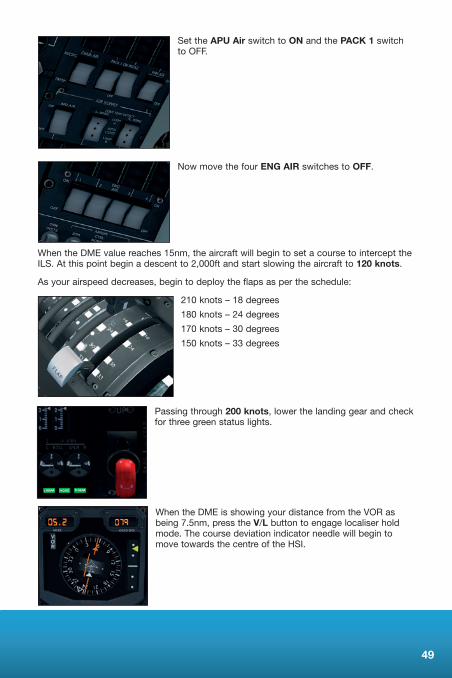
Set the APU Air switch to ON and the PACK 1 switch to OFF.
Now move the four ENG AIR switches to OFF.
When the DME value reaches 15nm, the aircraft will begin to set a course to intercept the ILS. At this point begin a descent to 2,000ft and start slowing the aircraft to 120 knots.
As your airspeed decreases, begin to deploy the flaps as per the schedule:
210 knots – 18 degrees
180 knots – 24 degrees
170 knots – 30 degrees
150 knots – 33 degrees
Passing through 200 knots, lower the landing gear and check for three green status lights.
When the DME is showing your distance from the VOR as being 7.5nm, press the V/L button to engage localiser hold mode. The course deviation indicator needle will begin to move towards the centre of the HSI.

50
The glideslope indicator will now begin to move down the scale on the attitude indicator. When the indicator reaches the dot above the central marker, press the GSL (glideslope) button to engage approach hold mode.
The aircraft will now pitch down to intercept the ILS. Keep the aircraft stable by maintaining 120 knots.
When the RAD ALT gauge reads 0500 (500 feet above ground level), disengage the autopilot and control the final phase of the approach by hand.
As the aircraft approaches the runway, start to bring the aircraft into a flare, gently raising the nose just above the horizon. Reduce the throttles to idle and the aircraft should touch down smoothly.
Deploy the airbrakes using the / (forward slash) key and ease the nose gear down onto the runway before commencing braking.
Once the aircraft has slowed to 25 knots, release the brakes and turn off on the first taxiway to the left. When you are safely off the runway, raise the flaps, switch off the strobe lights, and retract the airbrakes.
Switch off the landing lights and switch on the taxi lights before beginning your taxi to the terminal.
During the taxi, set the SCREEN HEAT, AUX & L.VANE, PITOT HTRS and R.VANE switches to OFF. Cancel the MWS caution light.
51
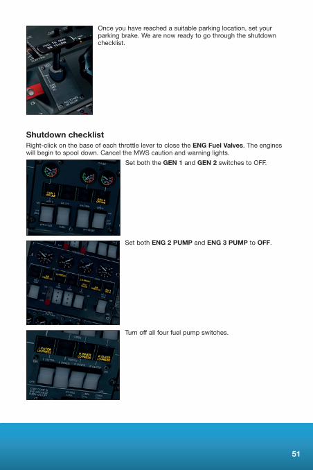
Once you have reached a suitable parking location, set your parking brake. We are now ready to go through the shutdown checklist.
Shutdown checklistRight-click on the base of each throttle lever to close the ENG Fuel Valves. The engines will begin to spool down. Cancel the MWS caution and warning lights.
Set both the GEN 1 and GEN 2 switches to OFF.
Set both ENG 2 PUMP and ENG 3 PUMP to OFF.
Turn off all four fuel pump switches.

52
Turn off the fasten seat belt sign, taxi, beacon and wing lights.
Set the AVIONICS MASTER switches to OFF.
Set the ANTI SKID and YEL and GRN LIFT SPLRS to OFF.
Turn OFF the FLT DECK and CABIN EMERG LTS.
Click on the APU AIR and PACK 2 switches to set them to OFF.
Turn off the APU and APU GEN.
Set the GALLEY/SHED switch to SHED.
Click on BATT 1 and BATT 2 to set them to OFF.
UsingtheGPUanddoorpanel,openthepassengerandcargodoorsandlowertheairstairs.
Congratulations, you have completed your first flight in the 146!
53
CHECKLISTS
Pre-flightExternal Checks Complete (doors closed) Battery Selector BATT1 / Check Volts BATT 1/BATT 2 ON (cancel MWS caution) Standby Inverter ARMED Parking Brake SET Fuel Pump 2 (left inner) ON APUGEN ON APU START (cancel MWS warning/caution) Emergency Lights ARMED Master Switches ALL ON Anti-Skid/Lift Spoilers ON Bus Ties BOTH AUTO StandbyGenerator ARMED APU Air / Pack 2 ON / ON DC Pump BATT Galley ONNo Smoking Signs ON Fasten Seat Belts ON Take-off Trim SETGPS InitialisedFuel Checked and sufficient for flight
Before startElectrical Fuel Pumps ALL ON Packs 2 / APU Air OFF / OFF Engine Anti-Ice ALL ON Wing Lights ON Pressurisation Checked and set (8,000ft for 29,000ft cruise) Air Conditioning Checked and setFuel Flow Meters Reset Altimeters Checked and set
StartingRotary Beacon ON Thrust Levers FUEL ONStart Master ON StartSelector ENGINENO.4 Engine START Oil Pressure Check for rising pressure N1/N2 Stable
(Repeat for engines 3, 2, and 1.)

54
After startStart Master OFF Start Selector OFFGenerator1and4 ONHydraulic Pump 2 and 3 ON / ON CHECKED (cancel MWS caution) Brake Fans AUTO APU Air / Packs 2 ON / ON DC Pump OFF Engine Anti-Ice ALL OFF Heaters ALL ON
TaxiTaxi Lights ON Nav Lights ON Flaps SET Yaw Damper ON Nav Aids and Flight Director SET Transponder SET Controls Full and free movement
Before take-offAC Pump ONLanding Lights ON Strobes ON WX Radar ON
After take-offGear UP/LIGHTSOUTFlaps UP AND INDICATED Engine Air ALL ON APU Air OFF Packs BOTH ON AC Pump OFF
Climb APU STOP Lights OFF AT FL100 Fasten Belts AS REQUIREDPressurisation Checked

55
DescentPressurisation Reset to ground level Fasten Seat Belts AS REQUIREDLights Landing light on at 10,000ft
ApproachAPU STARTED / CHECKED Altimeters CROSS-CHECKED
LandingGear DOWN3GREENSAPU Air ON Pack 1 OFF Engine Air OFF Lights AS REQUIREDFlaps SETFORLANDING
After landingStrobes/Landing OFF Taxi Lights ONAirbrakes/Spoilers IN WX Radar OFFFlaps SELECTED UPHeaters ALL OFF
ShutdownThrust Levers FUEL OFF Generators 1and4OFFHydraulics ALL OFF Fuel Pumps 1 / 3 / 4 OFF Fasten Seat Belts OFFTaxi Lights OFFBeacon OFFWing Lights OFF

56
Leaving aircraftMaster Switches OFF Anti-skid / Lift Spoilers OFF Emergency Lights OFFPack 2 / APU Air OFF / OFFAPU STOPAPUGenerator OFFFuel Pump 2 OFFGalley OFFLights OFF Batteries OFFBattery Selector OFF
Limits charts

57
CREDITS
Aircraft modelling and design – Commercial Level Simulations
Project Management – Alex Ford, Martyn Northall
Manual – Martyn Northall
Installer – Richard Slater
Sales – James, Harley and Jamie
Production Management – Andy Payne, Dermot Stapleton
Design – Fink Creative
Manufacturing – The Producers
Support–MartynNorthall,GeorgeBland
Special thanks to Matthias Lieberecht
COPYRIGHT
©2012 Just Flight Limited. All rights reserved. Just Flight and the Just Flight logo are trademarks of Just Flight Limited, 2 Stonehill, Stukeley Meadows, Huntingdon, PE29 6ED, UK. All trademarks and brand names are trademarks or registered trademarks of the respective owners and their use herein does not imply any association or endorsement by any third party.

58
SOFTWARE PIRACY
This software is copy protected.
We at Just Flight have invested significant time, effort and money to develop, manufacture and publish all of our flight simulation products. This includes rewarding the programmers and artists whose creativity contributes so much to the products we all enjoy.
A pirate, otherwise known as a thief, makes a profit from the sale of other people’s hard work. In some cases he makes more profit than the publishers and developers make from the sale of an original title. Piracy is not just the domain of the casual domestic user in his or her back room, but it is also a multi-million pound business conducted by criminals often with associations with the illegal drugs trade. Buying or downloading pirated copies of programs directly support these illegal operations.
Don’t be fooled by a load of old tosh about file ‘sharing’. The sites that host these ‘shared’ files are multi-million dollar operations that cover their backsides with the excuse that they are simply a ‘gateway’ to the files. In fact, they actively encourage piracy and are often funded by advertising. Most of them are illegal money-laundering operations by another name.
The people who really suffer from game piracy are the artists, programmers and other committed game development staff. Piracy and theft directly affects people, and their families. Loss of revenue to the games industry through piracy means many are losing their jobs due to cut-backs that have to be made to ensure developers and publishers survive. The logical outcome of this is that eventually the supply of flight simulation programs will dry up because developers think it is not worth the hassle.
It’s not just copying software that is against the law, owning copied software also constitutes a criminal offence; so anyone buying or downloading from these people is also at risk of arrest and prosecution.
To find out more about the implications of piracy please click on the Piracy link on our website at justflight.com.