operator and parts manual tandem disc - farm king · introduction - tandem disc 6650 7 introduction...
TRANSCRIPT

OPERATOR AND PARTS MANUAL
Tandem DiscModel 6650 - Medium Duty - 3 Section(Models after 04.01.2013 w/ serial number 54248 and higher.)
092015 88705168
6990633 (1-13) Printed in U.S.A. © Bobcat Company 2013 062013 | Rev 1 | 88664296


Table of Contents - Tandem Disc 6650
TABLE OF CONTENTS
INTRODUCTION . . . . . . . . . . . . . . . . . . . . . . . . . . . . . . . . . . . . . . . . . . . . . . . . . . . . . . . . . . . . . . . .7
SAFETY . . . . . . . . . . . . . . . . . . . . . . . . . . . . . . . . . . . . . . . . . . . . . . . . . . . . . . . . . . . . . . . . . . . . . . 11
ASSEMBLY . . . . . . . . . . . . . . . . . . . . . . . . . . . . . . . . . . . . . . . . . . . . . . . . . . . . . . . . . . . . . . . . . . . 23
OPERATION . . . . . . . . . . . . . . . . . . . . . . . . . . . . . . . . . . . . . . . . . . . . . . . . . . . . . . . . . . . . . . . . . . . 81
MAINTENANCE . . . . . . . . . . . . . . . . . . . . . . . . . . . . . . . . . . . . . . . . . . . . . . . . . . . . . . . . . . . . . . . . 97
PARTS IDENTIFICATION . . . . . . . . . . . . . . . . . . . . . . . . . . . . . . . . . . . . . . . . . . . . . . . . . . . . . . . . 119
SPECIFICATIONS . . . . . . . . . . . . . . . . . . . . . . . . . . . . . . . . . . . . . . . . . . . . . . . . . . . . . . . . . . . . . 175
WARRANTY . . . . . . . . . . . . . . . . . . . . . . . . . . . . . . . . . . . . . . . . . . . . . . . . . . . . . . . . . . . . . . . . . . 185
ALPHABETICAL INDEX . . . . . . . . . . . . . . . . . . . . . . . . . . . . . . . . . . . . . . . . . . . . . . . . . . . . . . . . . 189
Manufacturer’s Statement: For technical reasons, Buhler Industries Inc. reserves the right to modify machinery designand specifications provided herein without any preliminary notice. Information provided herein is of descriptive nature.Performance quality may depend on ground type, applied techniques, weather conditions and other factors.
3

Table of Contents - Tandem Disc 6650
4

Warranty Registration - Tandem Disc 6650
WARRANTY REGISTRATION FORM
This form must be filled out by the dealer and signed by both the dealer and the customer at the time of delivery.
I have thoroughly instructed the buyer on the above described equipment which review included the Operator’s Manualcontent, equipment care, adjustments, safe operation and applicable warranty policy.
The above equipment and Operator And Parts Manual have been received by me and I have been thoroughlyinstructed as to care, adjustments, safe operation and applicable warranty policy.
Customer Name: Dealer Name:
Customer Address: Dealer Address:
City: Prov / State: City: Prov / State:
Postal / Zip Code: Phone: Postal / Zip Code: Phone:
Equipment Name Model: Serial Number: Delivery Date:
Dealer Inspection Report SafetyScrapers Adjusted Properly All Lights And Reflectors Installed
Lubricate Machine All Lights And Reflectors Cleaned And Working
Level Machine Safety Chain On Hitch
Hydraulic Lockout Valves Function Properly All Decals Installed
Correct # Of Depth Stops Guards And Shields Installed And Secure
Wheel Bolt / Lug Nut Torque Review Operating And Safety Instructions
Fasteners Tight General Adjustment And Set-up Procedures
Front And Rear Gangs Set At Medium Angle Transportation Requirements And Regulations
Adjust Mounted Harrows As Required (if equipped)
Check Overlap Measurement Of Front Gangs
Check Opening Measurement Between Two Inner Blades Of Rear Main Frame Gangs
Hydraulic Cylinders
Hydraulic Hoses
Electrical Harness
Tire Pressure
Date: Dealer Rep. Signature:
Date: Customer / Owner’s Signature:
Remove this Warranty Registration Form from the Operator And Parts Manual. Make two copies of the form. Send original Warranty Registration Form to Farm King. Give one copy to the customer and the dealer will keep one copy.
5

Warranty Registration - Tandem Disc 6650
6

Introduction - Tandem Disc 6650
INTRODUCTION
This Operator And Parts Manual was written to give the owner / operator instructions on the safe operation, maintenanceand part identification of the Farm King equipment. READ AND UNDERSTAND THIS OPERATOR AND PARTS MANUALBEFORE OPERATING YOUR FARM KING EQUIPMENT. If you have any questions, see your Farm King dealer. Thismanual may illustrate options and accessories not installed on your Farm King equipment.
OWNER’S INFORMATION . . . . . . . . . . . . . . . . . . . . . . . . . . . . . . . . . . . . . . . . . . . . . . . . . . . . . . . . . 9Serial Number Location . . . . . . . . . . . . . . . . . . . . . . . . . . . . . . . . . . . . . . . . . . . . . . . . . . . . . . . . 9Manual Storage . . . . . . . . . . . . . . . . . . . . . . . . . . . . . . . . . . . . . . . . . . . . . . . . . . . . . . . . . . . . . . . 9
EQUIPMENT IDENTIFICATION . . . . . . . . . . . . . . . . . . . . . . . . . . . . . . . . . . . . . . . . . . . . . . . . . . . . 10Component Location . . . . . . . . . . . . . . . . . . . . . . . . . . . . . . . . . . . . . . . . . . . . . . . . . . . . . . . . . . 10
7

Introduction - Tandem Disc 6650
8
Introduction - Tandem Disc 6650
OWNER’S INFORMATION
Thank you for your decision to purchase a Farm King6650 Tandem Disc. To ensure maximum performance ofyour equipment, it is mandatory that you thoroughly studythe Operator And Parts Manual and follow therecommendations. Proper operation and maintenanceare essential to maximize equipment life and preventpersonal injury.
Operate and maintain this equipment in a safe mannerand in accordance with all applicable local, state, andfederal codes, regulations and / or laws. Follow all on-product labeling and instructions.
Make sure that all personnel have read this Operator andParts Manual and thoroughly understand safe andcorrect operating, installation and maintenanceprocedures.
Farm King is continually working to improve its products.Farm King reserves the right to make any improvementsor changes as deemed practical and possible withoutincurring any responsibility or obligation to make anychanges or additions to equipment sold previously.
Although great care has been taken to ensure theaccuracy of this publication, Farm King makes nowarranty or guarantee of any kind, written or expressed,implied or otherwise with regard to the informationcontained within this manual. Farm King assumes noresponsibility for any errors that may appear in thismanual and shall not be liable under any circumstancesfor incidental, consequential or punitive damages inconnection with, or arising from the use of this manual.
Keep this manual available for frequent reference. All newoperators or owners must review the manual before usingthe equipment and annually thereafter. Contact yourFarm King Dealer if you need assistance, information, oradditional copies of the manual. Visit our website atwww.farm-king.com for a complete list of dealers inyour area.
The directions left, right, front and rear, as mentionedthroughout this manual, are as seen facing in thedirection of travel of the implement.
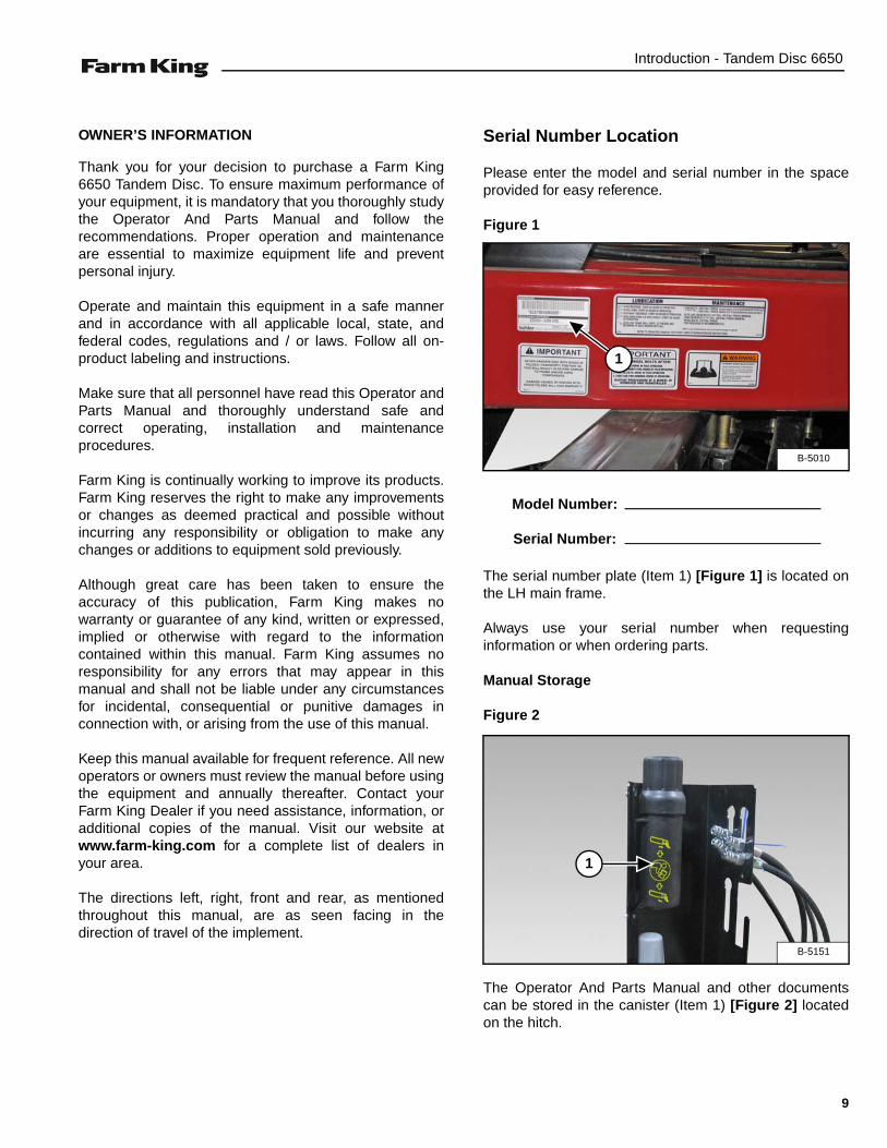
Serial Number Location
Please enter the model and serial number in the spaceprovided for easy reference.
Figure 1
The serial number plate (Item 1) [Figure 1] is located onthe LH main frame.
Always use your serial number when requestinginformation or when ordering parts.
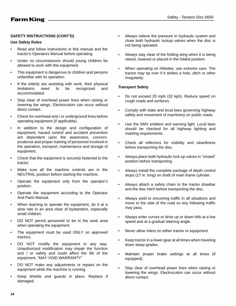
Manual Storage
Figure 2
The Operator And Parts Manual and other documentscan be stored in the canister (Item 1) [Figure 2] locatedon the hitch.
B-5010
1
Model Number:
Serial Number:
B-5151
1
9

Introduction - Tandem Disc 6650
EQUIPMENT IDENTIFICATION
Component Location
6650 IMAGE
HITCH
LEVELING CRANK
RH MAIN FRAME
LH MAIN FRAME
ROCK SHAFT
MAIN FRAME WHEELS
WING WHEELS
RH WING FRAME LIFT CYLINDER
LH WING FRAME LIFT CYLINDER
CENTER FRAME LIFT CYLINDER
WING LIFT CYLINDERS
JACK
BLADE
SCRAPER BAR
10
Safety - Tandem Disc 6650
SAFETY
SAFETY INSTRUCTIONS . . . . . . . . . . . . . . . . . . . . . . . . . . . . . . . . . . . . . . . . . . . . . . . . . . . . . . . . 13Safe Operation Is The Operator’s Responsibility . . . . . . . . . . . . . . . . . . . . . . . . . . . . . . . . . . . . 13Safe Operation Needs A Qualified Operator . . . . . . . . . . . . . . . . . . . . . . . . . . . . . . . . . . . . . . . . 13Use Safety Rules . . . . . . . . . . . . . . . . . . . . . . . . . . . . . . . . . . . . . . . . . . . . . . . . . . . . . . . . . . . . 14Transport Safety . . . . . . . . . . . . . . . . . . . . . . . . . . . . . . . . . . . . . . . . . . . . . . . . . . . . . . . . . . . . . 14Machine Requirements And Capabilities . . . . . . . . . . . . . . . . . . . . . . . . . . . . . . . . . . . . . . . . . .15
FIRE PREVENTION . . . . . . . . . . . . . . . . . . . . . . . . . . . . . . . . . . . . . . . . . . . . . . . . . . . . . . . . . . . . . 16Maintenance . . . . . . . . . . . . . . . . . . . . . . . . . . . . . . . . . . . . . . . . . . . . . . . . . . . . . . . . . . . . . . . . 16Operation . . . . . . . . . . . . . . . . . . . . . . . . . . . . . . . . . . . . . . . . . . . . . . . . . . . . . . . . . . . . . . . . . . 16Starting . . . . . . . . . . . . . . . . . . . . . . . . . . . . . . . . . . . . . . . . . . . . . . . . . . . . . . . . . . . . . . . . . . . . 16Electrical . . . . . . . . . . . . . . . . . . . . . . . . . . . . . . . . . . . . . . . . . . . . . . . . . . . . . . . . . . . . . . . . . . . 16Hydraulic System . . . . . . . . . . . . . . . . . . . . . . . . . . . . . . . . . . . . . . . . . . . . . . . . . . . . . . . . . . . . 16Fueling . . . . . . . . . . . . . . . . . . . . . . . . . . . . . . . . . . . . . . . . . . . . . . . . . . . . . . . . . . . . . . . . . . . . 16Welding And Grinding . . . . . . . . . . . . . . . . . . . . . . . . . . . . . . . . . . . . . . . . . . . . . . . . . . . . . . . . . 17Fire Extinguishers . . . . . . . . . . . . . . . . . . . . . . . . . . . . . . . . . . . . . . . . . . . . . . . . . . . . . . . . . . . .17
SAFETY SIGNS (DECALS) . . . . . . . . . . . . . . . . . . . . . . . . . . . . . . . . . . . . . . . . . . . . . . . . . . . . . . . 18
EQUIPMENT DECALS AND SIGNS . . . . . . . . . . . . . . . . . . . . . . . . . . . . . . . . . . . . . . . . . . . . . . . . 20
SAFETY SIGN-OFF FORM . . . . . . . . . . . . . . . . . . . . . . . . . . . . . . . . . . . . . . . . . . . . . . . . . . . . . . . 21
11

Safety - Tandem Disc 6650
12

Safety - Tandem Disc 6650
SAFETY INSTRUCTIONS
Safe Operation Is The Operator’s Responsibility
Safe Operation Needs A Qualified Operator
For an operator to be qualified, he or she must not usedrugs or alcoholic drinks which impair alertness orcoordination while working. An operator who is takingprescription drugs must get medical advice to determineif he or she can safely operate a machine and theequipment.
A Qualified Operator Must Do The Following:
Understand the Written Instructions, Rules andRegulations
• The written instructions from Farm King include theWarranty Registration, Dealer Inspection Report,Operator And Parts Manual and machine signs(decals).
• Check the rules and regulations at your location. Therules may include an employer’s work safetyrequirements. Regulations may apply to local drivingrequirements or use of a Slow Moving Vehicle (SMV)emblem. Regulations may identify a hazard such as autility line.
Have Training with Actual Operation
• Operator training must consist of a demonstration andverbal instruction. This training is given by themachine owner prior to operation.
• The new operator must start in an area withoutbystanders and use all the controls until he or she canoperate the machine safely under all conditions of thework area. Always fasten seat belt before operating.
Know the Work Conditions
• Clear working area of all bystanders, especially smallchildren and all obstacles that might be hooked orsnagged, causing injury or damage.
• Know the location of any overhead or undergroundpower lines. Call local utilities and have allunderground power lines marked prior to operation.
• Wear tight fitting clothing. Always wear safety glasseswhen doing maintenance or service.
This symbol with a warning statement means:“Warning, be alert! Your safety is involved!”Carefully read the message that follows.
Safety Alert Symbol
The signal word CAUTION on the machine and in themanuals indicates a potentially hazardous situationwhich, if not avoided, may result in minor ormoderate injury. It may also be used to alert againstunsafe practices.
The signal word DANGER on the machine and in themanuals indicates a hazardous situation which, ifnot avoided, will result in death or serious injury.
The signal word WARNING on the machine and inthe manuals indicates a potentially hazardoussituation which, if not avoided, could result in deathor serious injury.
This notice identifies procedures which must befollowed to avoid damage to the machine.
Operators must have instructions before operatingthe machine. Untrained operators can cause injuryor death.
13
Safety - Tandem Disc 6650
SAFETY INSTRUCTIONS (CONT’D)
Use Safety Rules
• Read and follow instructions in this manual and thetractor’s Operators Manual before operating.
• Under no circumstances should young children beallowed to work with this equipment.
• This equipment is dangerous to children and personsunfamiliar with its operation.
• If the elderly are assisting with work, their physicallimitations need to be recognized andaccommodated.
• Stay clear of overhead power lines when raising orlowering the wings. Electrocution can occur withoutdirect contact.
• Check for overhead and / or underground lines beforeoperating equipment (if applicable).
• In addition to the design and configuration ofequipment, hazard control and accident preventionare dependent upon the awareness, concern,prudence and proper training of personnel involved inthe operation, transport, maintenance and storage ofequipment.
• Check that the equipment is securely fastened to thetractor.
• Make sure all the machine controls are in theNEUTRAL position before starting the machine.
• Operate the equipment only from the operator’sposition.
• Operate the equipment according to the OperatorAnd Parts Manual.
• When learning to operate the equipment, do it at aslow rate in an area clear of bystanders, especiallysmall children.
• DO NOT permit personnel to be in the work areawhen operating the equipment.
• The equipment must be used ONLY on approvedtractors.
• DO NOT modify the equipment in any way.Unauthorized modification may impair the functionand / or safety and could affect the life of theequipment. “MAY VOID WARRANTY”
• DO NOT make any adjustments or repairs on theequipment while the machine is running.
• Keep shields and guards in place. Replace ifdamaged.
• Always relieve the pressure in hydraulic system andclose both hydraulic lockup valves when the disc isnot being operated.
• Always stay clear of the folding wing when it is beingraised, lowered or placed in the folded position.
• When operating on hillsides, use extreme care. Thetractor may tip over if it strikes a hole, ditch or otherirregularity.
Transport Safety
• Do not exceed 20 mph (32 kph). Reduce speed onrough roads and surfaces.
• Comply with state and local laws governing highwaysafety and movement of machinery on public roads.
• Use the SMV emblem and warning light. Local lawsshould be checked for all highway lighting andmarking requirements.
• Check all reflectors for visibility and cleanlinessbefore transporting the disc.
• Always place both hydraulic lock up valves in “closed”position before transporting.
• Always install the complete package of depth controlstops (17 in. long) on shaft of main frame cylinder.
• Always attach a safety chain to the tractor drawbarand the disc hitch before transporting the disc.
• Always yield to oncoming traffic in all situations andmove to the side of the road so any following trafficmay pass.
• Always enter curves or drive up or down hills at a lowspeed and at a gradual steering angle.
• Never allow riders on either tractor or equipment.
• Keep tractor in a lower gear at all times when travelingdown steep grades.
• Maintain proper brake settings at all times (ifequipped).
• Stay clear of overhead power lines when raising orlowering the wings. Electrocution can occur withoutdirect contact.
14

Safety - Tandem Disc 6650
Machine Requirements And Capabilities
• Fasten seat belt securely. If equipped with a foldableRoll-Over Protective Structure (ROPS), only fastenseat belt when ROPS is up and locked. DO NOT wearseat belt if ROPS is down.
• Stop the machine and engage the parking brake.Install blocks in front of and behind the rear tires of themachine. Install blocks underneath and support theequipment securely before working under raisedequipment.
• Keep bystanders clear of moving parts and the workarea. Keep children away.
• Use increased caution on slopes and near banks andditches to prevent overturn.
• Make certain that the Slow Moving Vehicle (SMV)emblem is installed so that it is visible and legible.When transporting the equipment, use the flashingwarning lights (if equipped) and follow all localregulations.
• Operate this equipment with a machine equipped withan approved Roll-Over Protective Structure (ROPS).Always wear seat belt when the ROPS is up. Seriousinjury or death could result from falling off themachine.
• Before leaving the operator’s position:
1. Always park on a flat level surface.2. Place all controls in neutral.3. Engage the parking brake.4. Stop engine.5. Wait for all moving parts to stop.
• Carry passengers only in designated seating areas.Never allow riders on the machine or equipment.Falling off can result in serious injury or death.
• Start the equipment only when properly seated in theoperator’s seat. Starting a machine in gear can resultin serious injury or death.
• Operate the machine and equipment from theoperator's position only.
• The parking brake must be engaged before leavingthe operator’s seat. Rollaway can occur because thetransmission may not prevent machine movement.
15
Safety - Tandem Disc 6650
FIRE PREVENTION
Maintenance
The machine and some equipment have componentsthat are at high temperatures under normal operatingconditions. The primary source of high temperatures isthe engine and exhaust system. The electrical system, ifdamaged or incorrectly maintained, can be a source ofarcs or sparks.
Flammable debris (leaves, straw, etc.) must be removedregularly. If flammable debris is allowed to accumulate, itcan cause a fire hazard. Clean often to avoid thisaccumulation. Flammable debris in the enginecompartment is a potential fire hazard.
The operator’s area, engine compartment and enginecooling system must be inspected every day and cleanedif necessary to prevent fire hazards and overheating.
All fuels, most lubricants and some coolant mixtures areflammable. Flammable fluids that are leaking or spilledonto hot surfaces or onto electrical components cancause a fire.
Operation
The Farm King machine must be in good operatingcondition before use.
Check all of the items listed on the service scheduleunder the 8 hour column. (See “SERVICE SCHEDULE”on page 101.)
Do not use the machine where exhaust, arcs, sparks orhot components can contact flammable material,explosive dust or gases.
Starting
Do not use ether or starting fluids on any engine that hasglow plugs. These starting aids can cause explosion andinjure you or bystanders.
Use the procedure in the tractor’s operator’s manual forconnecting the battery and for jump starting.
Electrical
Check all electrical wiring and connections for damage.Keep the battery terminals clean and tight. Repair orreplace any damaged part or wires that are loose orfrayed.
Battery gas can explode and cause serious injury. Do notjump start or charge a frozen or damaged battery. Keepany open flames or sparks away from batteries. Do notsmoke in battery charging area.
Hydraulic System
Check hydraulic tubes, hoses and fittings for damageand leakage. Never use open flame or bare skin to checkfor leaks. Hydraulic tubes and hoses must be properlyrouted and have adequate support and secure clamps.Tighten or replace any parts that show leakage.
Always clean fluid spills. Do not use gasoline or dieselfuel for cleaning parts. Use commercial nonflammablesolvents.
Fueling
Stop the engine and let it cool before adding fuel. Nosmoking! Do not refuel a machine near open flames orsparks. Fill the fuel tank outdoors.
16

Safety - Tandem Disc 6650
FIRE PREVENTION (CONT’D)
Welding And Grinding
Always clean the machine and equipment, disconnectthe battery, and disconnect the wiring from the machinecontrols before welding. Cover rubber hoses, battery andall other flammable parts. Keep a fire extinguisher nearthe machine when welding.
Have good ventilation when grinding or welding paintedparts. Wear dust mask when grinding painted parts.Toxic dust or gas can be produced.
Dust generated from repairing nonmetallic parts such ashoods, fenders or covers can be flammable or explosive.Repair such components in a well ventilated area awayfrom open flames or sparks.
Fire Extinguishers
Know where fire extinguishers and first aid kits arelocated and how to use them. Inspect the fireextinguisher and service the fire extinguisher regularly.Obey the recommendations on the instructions plate.
17
Safety - Tandem Disc 6650
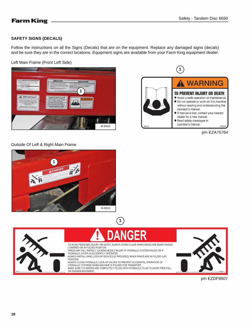
SAFETY SIGNS (DECALS)
Follow the instructions on all the Signs (Decals) that are on the equipment. Replace any damaged signs (decals)and be sure they are in the correct locations. Equipment signs are available from your Farm King equipment dealer.
Left Main Frame (Front Left Side)
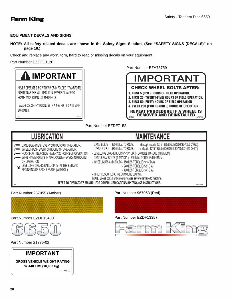
Outside Of Left & Right Main Frame
B-5010
1
1
p/n EZA75764
TO AVOID PERSONAL INJURY OR DEATH, ALWAYS STAND CLEAR WHEN WINGS ARE BEING RAISED, LOWERED OR IN FOLDED POSITION.WINGS MAY FALL RAPIDLY, CAUSING BODILY INJURY IF HYDRAULIC SYSTEM FAILED OR IFHYDRAULIC LEVER IS ACCIDENTLY OPERATED.ALWAYS INSTALL WING LOCK-UP DEVICES (IF PROVIDED) WHEN WINGS ARE IN FOLDED (UP) POSITION.ALWAYS CLOSE HYDRAULIC LOCK-UP VALVES TO PREVENT ACCIDENTAL OPERATION OF HYDRAULIC SYSTEMS WHEN MACHINE IS FOLDED FOR TRANSPORT.MAKE SURE CYLINDERS ARE COMPLETELY FILLED WITH HYDRAULIC FLUID TO AVOID FREE-FALL OR SUDDEN MOVEMENT. BS13
DANGER
DF9507
B-5012
1
1
p/n EZDF9507
18

Safety - Tandem Disc 6650
Front Of Main Frame
B-5011
1
2
3
1
p/n EZDF13001
p/n EZDF9510
2
p/n EZDF9510
3
19
Safety - Tandem Disc 6650
EQUIPMENT DECALS AND SIGNS
NOTE: All safety related decals are shown in the Safety Signs Section. (See “SAFETY SIGNS (DECALS)” onpage 18.)
Check and replace any worn, torn, hard to read or missing decals on your equipment.
Part Number EZDF13120
Part Number EZDF7152
DF13120
IMPORTANT
B13
Part Number EZA75759
GANG BEARINGS - EVERY 20 HOURS OF OPERATION.WHEEL HUBS - EVERY 50 HOURS OF OPERATION.ROCKSHAFT BEARINGS - EVERY 20 HOURS OF OPERATION.WING HINGE POINTS (IF APPLICABLE) - EVERY 100 HOURS OF OPERATION.LEVELLING CRANK (BALL JOINT) - AT THE END ANDBEGINNING OF EACH SEASON (WITH OIL).
BS13 REFER TO OPERATOR'S MANUAL FOR OTHER LUBRICATION/MAINTENANCE INSTRUCTIONS. DF7152
- LEVELLING CRANK BOLTS (1-1/4" DIA.) - 840 ft/lbs TORQUE (MINIMUM).- GANG BEAM BOLTS (1-1/4" DIA.) - 840 ft/lbs. TORQUE (MINIMUM).- WHEEL NUTS AND BOLTS - 150 LBS TORQUE (9/16" DIA) - 240 LBS TORQUE (5/8" DIA) - 420 LBS TORQUE (3/4" DIA)- TIRE PRESSURES AT RECOMMENDED P.S.I.NOTE: Loose bolts/hardware may cause severe damage to machine.
LUBRICATION MAINTENANCE(Except models 1275/1375/8550/SD650/SD750/SD1050)- GANG BOLTS - 3200 ft/lbs. TORQUE.
- 3800 ft/lbs. TORQUE. ( Models 1275/1375/8550/SD650/SD750/SD1050 ONLY)(1-15/16" DIA.)
IMPORTANTGROSS VEHICLE WEIGHT RATING
37,440 LBS (16,983 kg)21975-02
Part Number 967055 (Amber) Part Number 967053 (Red)
Part Number EZDF13400 Part Number EZDF13357
Part Number 21975-02
20

Safety - Tandem Disc 6650
SAFETY SIGN-OFF FORM
Farm King follows the general Safety Standards specified by the American Society of Agricultural and BiologicalEngineers (ASABE) and the Occupational Safety and Health Administration (OSHA). Anyone who will be operating and /or maintaining the 6650 Tandem Disc must read and clearly understand ALL Safety, Operating and Maintenanceinformation presented in this manual.
Annually review this information before the season start-up and make these periodic reviews of SAFETY andOPERATION a standard practice for all of your equipment. An untrained operator is unqualified to operate thismachine.
The following sign-off sheet is provided for your record and to show that all personnel who will be working with theequipment have read and understand the information in this Operator And Parts Manual and have been instructed in theoperation of the equipment.
SIGN-OFF SHEET
Date Employee’s Signature Employer’s Signature
Instructions are necessary before operating or servicing equipment. Read and understand theOperator And Parts Manual and safety signs (decals) on equipment. Follow warnings andinstructions in the manuals when making repairs, adjustments or servicing. Check for correctfunction after adjustments, repairs or service. Untrained operators and failure to follow instructionscan cause injury or death.
21

Safety - Tandem Disc 6650
22
Assembly - Tandem Disc 6650
ASSEMBLY
GENERAL ASSEMBLY INFORMATION . . . . . . . . . . . . . . . . . . . . . . . . . . . . . . . . . . . . . . . . . . . . . 25Component Unloading And Identification . . . . . . . . . . . . . . . . . . . . . . . . . . . . . . . . . . . . . . . . . .25
BASE GROUP . . . . . . . . . . . . . . . . . . . . . . . . . . . . . . . . . . . . . . . . . . . . . . . . . . . . . . . . . . . . . . . . . 26Main Frame Assembly . . . . . . . . . . . . . . . . . . . . . . . . . . . . . . . . . . . . . . . . . . . . . . . . . . . . . . . .26Installing The Main Frame Rockshaft . . . . . . . . . . . . . . . . . . . . . . . . . . . . . . . . . . . . . . . . . . . . . 28Installing The Main Frame Spindles and Wheels . . . . . . . . . . . . . . . . . . . . . . . . . . . . . . . . . . . . 32Installing The Hitch . . . . . . . . . . . . . . . . . . . . . . . . . . . . . . . . . . . . . . . . . . . . . . . . . . . . . . . . . . . 33Installing The Leveling Crank Assembly . . . . . . . . . . . . . . . . . . . . . . . . . . . . . . . . . . . . . . . . . . . 34Installing The Wing Frames . . . . . . . . . . . . . . . . . . . . . . . . . . . . . . . . . . . . . . . . . . . . . . . . . . . . 35Installing The Wing Rockshafts . . . . . . . . . . . . . . . . . . . . . . . . . . . . . . . . . . . . . . . . . . . . . . . . . . 37
HYDRAULICS . . . . . . . . . . . . . . . . . . . . . . . . . . . . . . . . . . . . . . . . . . . . . . . . . . . . . . . . . . . . . . . . . 41Installing Main Frame Rockshaft Hydraulic Cylinder . . . . . . . . . . . . . . . . . . . . . . . . . . . . . . . . . . 41Installing Wing Lift Cylinders . . . . . . . . . . . . . . . . . . . . . . . . . . . . . . . . . . . . . . . . . . . . . . . . . . . . 43Installing Wing Rockshaft Hydraulic Cylinders . . . . . . . . . . . . . . . . . . . . . . . . . . . . . . . . . . . . . . 44Installing Hydraulic Control Valves . . . . . . . . . . . . . . . . . . . . . . . . . . . . . . . . . . . . . . . . . . . . . . . 45Installing Hydraulic Fittings . . . . . . . . . . . . . . . . . . . . . . . . . . . . . . . . . . . . . . . . . . . . . . . . . . . . .46Hydraulic Hose Identification - Narrow Wing . . . . . . . . . . . . . . . . . . . . . . . . . . . . . . . . . . . . . . . 49Hydraulic Hose Identification - Wide Wing . . . . . . . . . . . . . . . . . . . . . . . . . . . . . . . . . . . . . . . . . 50Hydraulic Hose Installation And Routing . . . . . . . . . . . . . . . . . . . . . . . . . . . . . . . . . . . . . . . . . . . 51
PURGING / REPHASING HYDRAULIC SYSTEM . . . . . . . . . . . . . . . . . . . . . . . . . . . . . . . . . . . . . . 56Purging Hydraulic System . . . . . . . . . . . . . . . . . . . . . . . . . . . . . . . . . . . . . . . . . . . . . . . . . . . . . . 56Rephasing Hydraulic System . . . . . . . . . . . . . . . . . . . . . . . . . . . . . . . . . . . . . . . . . . . . . . . . . . . 56
GANG SECTIONS . . . . . . . . . . . . . . . . . . . . . . . . . . . . . . . . . . . . . . . . . . . . . . . . . . . . . . . . . . . . . . 57Gang Beam Extension Chart . . . . . . . . . . . . . . . . . . . . . . . . . . . . . . . . . . . . . . . . . . . . . . . . . . . 57General Information . . . . . . . . . . . . . . . . . . . . . . . . . . . . . . . . . . . . . . . . . . . . . . . . . . . . . . . . . . 58Installing The Gang Extensions . . . . . . . . . . . . . . . . . . . . . . . . . . . . . . . . . . . . . . . . . . . . . . . . .59Installing The Gang Sections . . . . . . . . . . . . . . . . . . . . . . . . . . . . . . . . . . . . . . . . . . . . . . . . . . . 61Installing The Scraper Bar And Scrapers . . . . . . . . . . . . . . . . . . . . . . . . . . . . . . . . . . . . . . . . . .69Installing Hydraulic Hose Bracket . . . . . . . . . . . . . . . . . . . . . . . . . . . . . . . . . . . . . . . . . . . . . . . . 71Installing Manual Storage Container . . . . . . . . . . . . . . . . . . . . . . . . . . . . . . . . . . . . . . . . . . . . . .72
LIGHT KIT . . . . . . . . . . . . . . . . . . . . . . . . . . . . . . . . . . . . . . . . . . . . . . . . . . . . . . . . . . . . . . . . . . . . 73Installation . . . . . . . . . . . . . . . . . . . . . . . . . . . . . . . . . . . . . . . . . . . . . . . . . . . . . . . . . . . . . . . . . . 73
DEPTH STOPS . . . . . . . . . . . . . . . . . . . . . . . . . . . . . . . . . . . . . . . . . . . . . . . . . . . . . . . . . . . . . . . . 75
23
Assembly - Tandem Disc 6650
GANG PATTERNS . . . . . . . . . . . . . . . . . . . . . . . . . . . . . . . . . . . . . . . . . . . . . . . . . . . . . . . . . . . . . .769 Inch Spacing - 70 Blades / 22 Bearings . . . . . . . . . . . . . . . . . . . . . . . . . . . . . . . . . . . . . . . . . .769 Inch Spacing - 78 Blades / 24 Bearings . . . . . . . . . . . . . . . . . . . . . . . . . . . . . . . . . . . . . . . . . .769 Inch Spacing - 86 Blades / 26 Bearings . . . . . . . . . . . . . . . . . . . . . . . . . . . . . . . . . . . . . . . . . .779 Inch Spacing - 94 Blades / 28 Bearings . . . . . . . . . . . . . . . . . . . . . . . . . . . . . . . . . . . . . . . . . .7710-1/2 Inch Spacing - 58 Blades / 20 Bearings . . . . . . . . . . . . . . . . . . . . . . . . . . . . . . . . . . . . . .7810-1/2 Inch Spacing - 66 Blades / 24 Bearings . . . . . . . . . . . . . . . . . . . . . . . . . . . . . . . . . . . . . .7810-1/2 Inch Spacing - 74 Blades / 24 Bearings . . . . . . . . . . . . . . . . . . . . . . . . . . . . . . . . . . . . . .7910-1/2 Inch Spacing - 82 Blades / 26 Bearings . . . . . . . . . . . . . . . . . . . . . . . . . . . . . . . . . . . . . .79
24

Assembly - Tandem Disc 6650
GENERAL ASSEMBLY INFORMATION
Component Unloading And Identification
Unload the crate(s) and components on a flat level areaof adequate size to assemble the 6650 Tandem Disc.
NOTE: If any components are damaged, missing orreplacement parts are required, contact yourFarm King Dealer.
Assemble the 6650 Tandem Disc in the following order:
Using the packing list, locate and place allcomponents and hardware in one area. Count theindividual components and verify that you havereceived the correct number of components to fullyassemble the 6650 Tandem Disc.
1. Main Frame (See “Main Frame Assembly” onpage 26.)
2. Wings (See “Installing The Wing Frames” onpage 35.)
3. Hydraulics (See “HYDRAULICS” on page 41.)
4. Gang Extensions (See “Installing The GangExtensions” on page 59.)
5. Gang Sections (See “GANG SECTIONS” onpage 57.)
Figure 3
Larger components are marked for identification [Figure3].
ELECTROCUTION HAZARDTo prevent serious injury or death fromelectrocution:
• Be aware of overhead power lines.• Keep away from power lines when unloading and
assembling the tandem disc.• Electrocution can occur without direct contact.
• DO NOT permit bystanders to be in the work areawhen unloading and assembling the tandem disccomponents.
• DO NOT work under suspended parts.
• Keep away from moving parts.
• Always use lifting devices / vehicles, chains orstraps of adequate size and strength whenunloading and assembling the tandem disccomponents.
Unload crate(s) and tandem disc componentscarefully to prevent damage to any of thecomponents.
B-5076
EXAMPLE
25
Assembly - Tandem Disc 6650
BASE GROUP
Main Frame Assembly
Assemble the main frame on a flat level surface.
NOTE: The following images throughout theassembly section of this manual may notshow your exact tandem disc components asthey appear but the procedure is correct forall 6650 Tandem Discs.
NOTE: Support stands approximately 36 inches(914.4 mm) high equipped with rotatingcasters / wheels are recommended whenassembling the main frame of the tandemdisc.
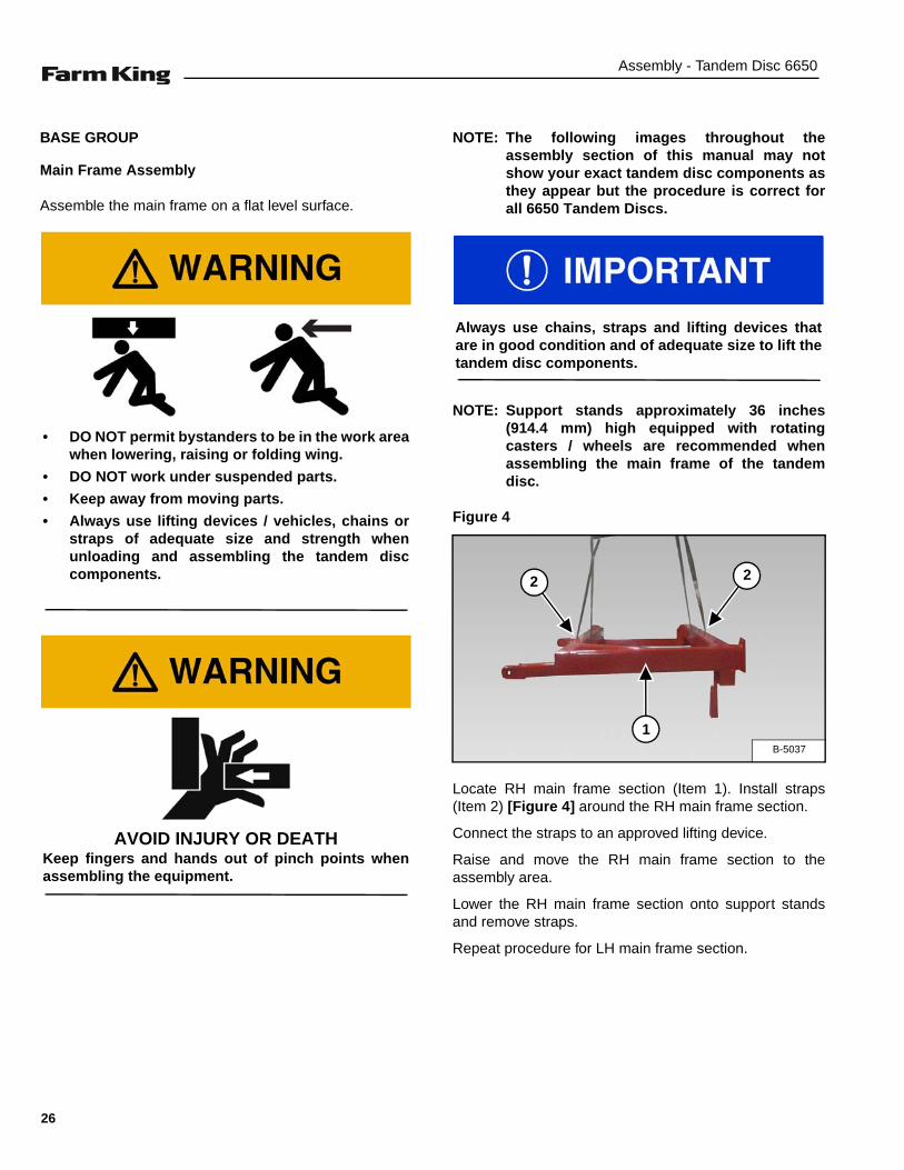
Figure 4
Locate RH main frame section (Item 1). Install straps(Item 2) [Figure 4] around the RH main frame section.
Connect the straps to an approved lifting device.
Raise and move the RH main frame section to theassembly area.
Lower the RH main frame section onto support standsand remove straps.
Repeat procedure for LH main frame section.
• DO NOT permit bystanders to be in the work areawhen lowering, raising or folding wing.
• DO NOT work under suspended parts.
• Keep away from moving parts.
• Always use lifting devices / vehicles, chains orstraps of adequate size and strength whenunloading and assembling the tandem disccomponents.
AVOID INJURY OR DEATHKeep fingers and hands out of pinch points whenassembling the equipment.
Always use chains, straps and lifting devices thatare in good condition and of adequate size to lift thetandem disc components.
B-5037
1
22
26
Assembly - Tandem Disc 6650
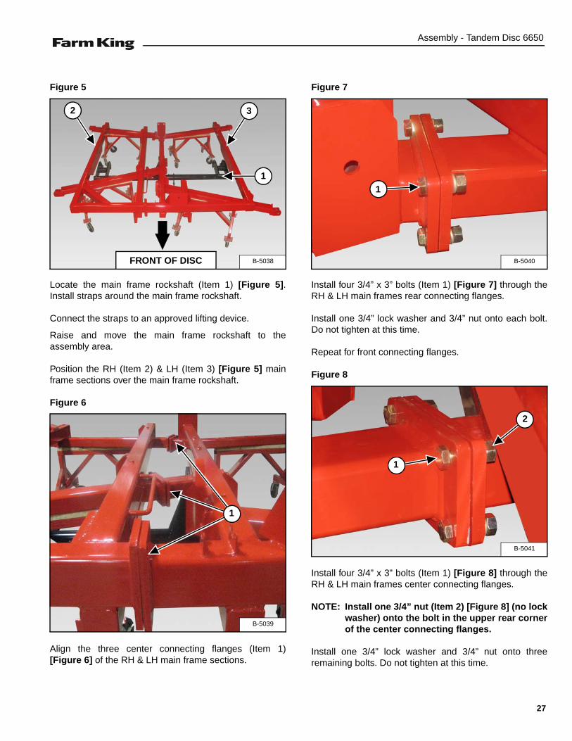
Figure 5
Locate the main frame rockshaft (Item 1) [Figure 5].Install straps around the main frame rockshaft.
Connect the straps to an approved lifting device.
Raise and move the main frame rockshaft to theassembly area.
Position the RH (Item 2) & LH (Item 3) [Figure 5] mainframe sections over the main frame rockshaft.
Figure 6
Align the three center connecting flanges (Item 1)[Figure 6] of the RH & LH main frame sections.
Figure 7
Install four 3/4” x 3” bolts (Item 1) [Figure 7] through theRH & LH main frames rear connecting flanges.
Install one 3/4” lock washer and 3/4” nut onto each bolt.Do not tighten at this time.
Repeat for front connecting flanges.
Figure 8
Install four 3/4” x 3” bolts (Item 1) [Figure 8] through theRH & LH main frames center connecting flanges.
NOTE: Install one 3/4” nut (Item 2) [Figure 8] (no lockwasher) onto the bolt in the upper rear cornerof the center connecting flanges.
Install one 3/4” lock washer and 3/4” nut onto threeremaining bolts. Do not tighten at this time.
B-5038
1
FRONT OF DISC
2 3
B-5039
1
B-5040
1
B-5041
1
2
27

Assembly - Tandem Disc 6650
Installing The Main Frame Rockshaft
Figure 9
Locate the upper rockshaft bearings (Item 1) [Figure 9].
Locate and install grease fitting (Item 2) [Figure 9] (ifrequired).
Apply thin layer of grease to rockshaft bearings.
Figure 10
Locate the lower rockshaft bearings (Item 1) [Figure 10].
Locate and install grease fitting (Item 2) [Figure 10] (ifrequired).
Apply thin layer of grease to rockshaft bearings.
B-5042
1
UPPER ROCKSHAFT BEARING
2
UPPER ROCKSHAFT BEARINGS
Always install the upper rockshaft bearings with thegrease fitting on the same side as the tire attached,except for the center rockshaft bearing. Alwaysinstall the center upper rockshaft bearing with thegrease fitting towards the rear.
B-5043
1
LOWER ROCKSHAFT BEARING
2
LOWER ROCKSHAFT BEARINGS
Always install the lower rockshaft bearings with thegrease fitting opposite of the upper rockshaftbearing grease fitting.
28

Assembly - Tandem Disc 6650
Figure 11
Install straps (Item 1) around the main frame rockshaft(Item 2) [Figure 11].
Connect the straps to an approved lifting device.
Figure 12
Raise the main frame rockshaft (Do not contact mainframe sections).
Align / center the two tabs (Item 1) below the rockshaftbearing mount (Item 2) [Figure 12] (center rockshaftbearing).
Figure 13
Place one upper rockshaft bearing (Item 1) [Figure 13](with grease fitting towards the rear) onto the rockshaft(center location).
Figure 14
Raise rockshaft (Item 1) slightly, allowing adequate spacebetween the rockshaft and RH rockshaft bearing mount(Item 2) [Figure 14] to install upper rockshaft bearing.
B-5044
2
1
1
B-50451
2
B-5047
1
B-5046
1
2
29

Assembly - Tandem Disc 6650
Figure 15
Place one upper rockshaft bearing (Item 1) [Figure 15]onto the rockshaft.
Raise the rockshaft, aligning the upper rockshaft bearingbetween the two tabs (Item 2) [Figure 15] on therockshaft bearing mount. Continue raising the rockshaftuntil the upper bearing contacts the mount.
NOTE: Verify that center rockshaft bearing tabs arestill in line with the center rockshaft bearingmount.
Align and install lower rockshaft bearing (Item 3) [Figure15] (grease fitting facing towards the front).
Install two 3/4” x 6-1/2” Grade 5 bolts (Item 4) [Figure 15]up through the lower, upper rockshaft bearings andmount. Install one 3/4 lock washer and 3/4” nut onto eacheach bolt. Do not tighten at this time.
Repeat procedure for LH upper & lower bearing.
Figure 16
Raise the rockshaft, aligning the upper rockshaft bearingbetween the two tabs on the center rockshaft bearingmount. Continue raising the rockshaft until the upperbearing contacts the mount.
Align and install center lower rockshaft bearing (Item 1)[Figure 16] (grease fitting facing towards the front).
Install two 3/4” x 6-1/2” Grade 5 bolts (Item 2) [Figure 16]through the lower, upper rockshaft bearings and mount.Install one 3/4 lock washer and 3/4” nut onto each bolt.Do not tighten at this time.
Verify all bearing grease fittings are facing the correctdirections.
Tighten the rockshaft bearings.
Slowly lower the main frame rockshaft.
NOTE: Rockshaft must move / rotate freely inside theupper & lower rockshaft bearings.
B-5049
1
22
34
B-5048
12
If the main frame rockshaft does not move / rotatefreely, install shims between lower and upperrockshaft bearings as needed until the main framerockshaft moves / rotates freely.
30

Assembly - Tandem Disc 6650
Figure 17
Tighten the four 3/4” x 3” bolts (Item 1) [Figure 17] on therear RH & LH main frame connecting flanges.
Repeat for front connecting flanges.
Figure 18
Tighten four 3/4” x 3” bolts (Item 1) [Figure 18] on thecenter RH & LH main frame connecting flanges.
B-5040
1
If the center LH and RH main frame connectingflanges have a gap after tightening the front and rearconnecting flanges, install two hole shims betweencenter connecting flanges to take up the gap.
B-5041
1
31
Assembly - Tandem Disc 6650
Installing The Main Frame Spindles and Wheels
NOTE: The following procedure shows the spindlesand wheels on the RH side of the main frame.The procedure is the same for the LH side ofthe main frame.
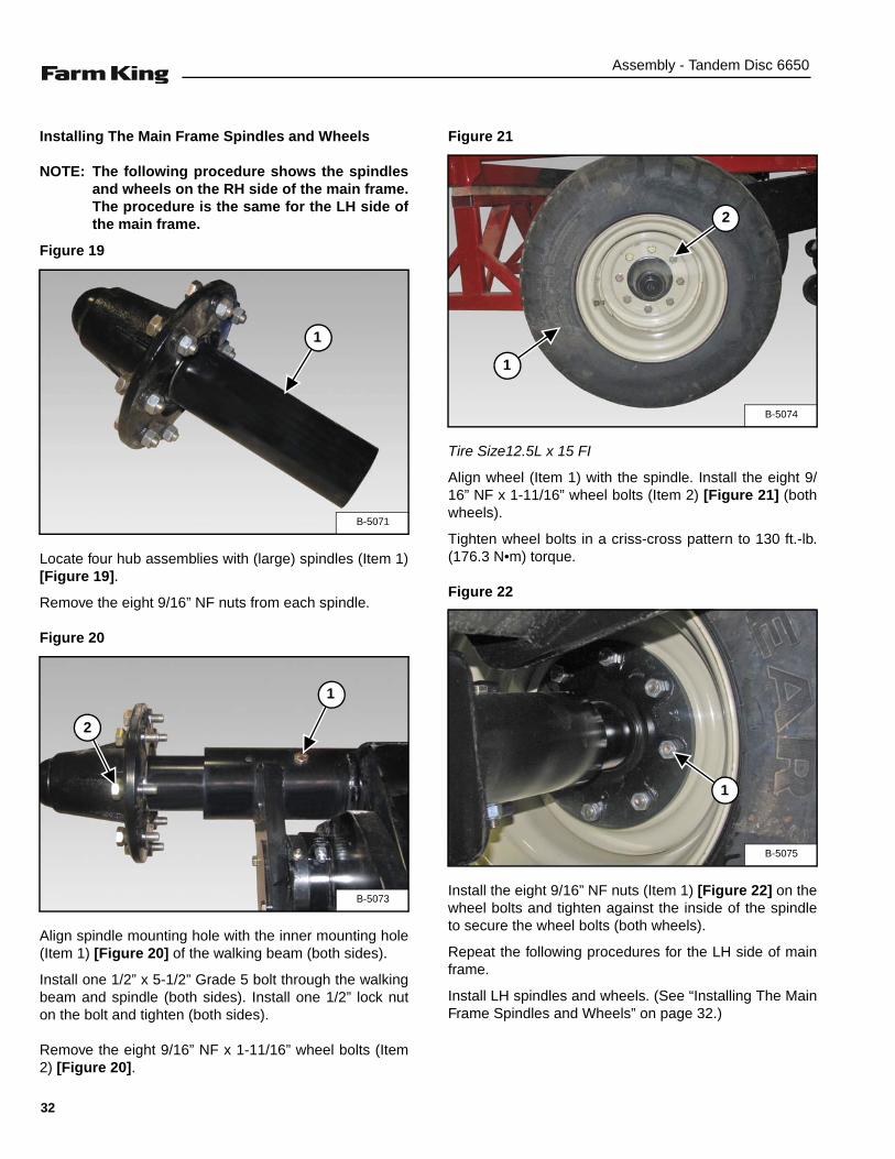
Figure 19
Locate four hub assemblies with (large) spindles (Item 1)[Figure 19].
Remove the eight 9/16” NF nuts from each spindle.
Figure 20
Align spindle mounting hole with the inner mounting hole(Item 1) [Figure 20] of the walking beam (both sides).
Install one 1/2” x 5-1/2” Grade 5 bolt through the walkingbeam and spindle (both sides). Install one 1/2” lock nuton the bolt and tighten (both sides).
Remove the eight 9/16” NF x 1-11/16” wheel bolts (Item2) [Figure 20].
Figure 21
Tire Size12.5L x 15 FI
Align wheel (Item 1) with the spindle. Install the eight 9/16” NF x 1-11/16” wheel bolts (Item 2) [Figure 21] (bothwheels).
Tighten wheel bolts in a criss-cross pattern to 130 ft.-lb.(176.3 N•m) torque.
Figure 22
Install the eight 9/16” NF nuts (Item 1) [Figure 22] on thewheel bolts and tighten against the inside of the spindleto secure the wheel bolts (both wheels).
Repeat the following procedures for the LH side of mainframe.
Install LH spindles and wheels. (See “Installing The MainFrame Spindles and Wheels” on page 32.)
B-5071
1
B-5073
1
2
B-5074
1
2
B-5075
1
32

Assembly - Tandem Disc 6650
Installing The Hitch
Figure 23
Locate the hitch assembly (Item 1) [Figure 23]. Installstraps around the hitch assembly.
Connect the straps to an approved lifting device.
Raise and move the hitch assembly to the assemblyarea.
Figure 24
Lower and guide the hitch assembly (Item 1) under thefront of the main frame assembly, below the compressionspring mounting plate (Item 2) [Figure 24].
Figure 25
Raise the hitch assembly, aligning the hitch mounts withthe mounting brackets on the main frame.
Place floor jack (Item 1) [Figure 25] under the RH sidehitch mount (helps stabilize hitch). Raise the floor jackand lifting device at the same time until the hitch mountsare in line with the main frame mounting brackets.
Figure 26
Locate the two hitch mounting pins (Item 1) [Figure 26].
Install the hitch mounting pin through the outer hitchmount, main frame mounting bracket and inner hitchmount (both sides).
Install one locking hitch pin (Item 2) [Figure 26] to securethe hitch to the main frame.
B-5079
1
B-5080
1
2
B-5081
1
B-5082
1
2
33

Assembly - Tandem Disc 6650
Installing The Leveling Crank Assembly
Figure 27
Locate the leveling crank assembly (Item 1) [Figure 27].Install straps around the leveling crank assembly.
Connect the straps to an approved lifting device.
Raise and move the leveling crank assembly to theassembly area.
Figure 28
Lower the leveling crank assembly (Item 1) so lugs (Item2) on trunion tube can be installed in hitch leveling armlugs (Item 3) [Figure 28].
NOTE: Be sure grease fitting on trunion tube isfacing up.
Figure 29
Position the clevis end (Item 1) of the leveling crankassembly over the connecting link (Item 2) [Figure 29] onthe rockshaft (just left of center).
Lubricate ball in ball joint (Item 4) [Figure 29] so it canrotate freely.
Install one 1-1/4” x 4-3/4” bolt (Item 3) [Figure 29]through the clevis and connecting link. Install one 1-1/4”lock washer and nut on the bolt and tighten.
NOTE: Tighten bolt (Item 3) so it is tight against balljoint (Item 4) [Figure 29].
Figure 30
Locate four 1/2” x 5” Grade 5 bolts (Item 1), four 1/2” lockwashers, four 1/2” nuts and the leveling lug hitch plate(Item 2) [Figure 30].
Install the leveling lug hitch plate onto the peg (Item 3)[Figure 30] of the leveling crank.
Install the four 1/2” x 5” Grade 5 bolts through the levelinglug hitch plate and leveling crank assembly. Install one 1/2” lock washer and 1/2” nut on each bolt and tighten.
Remove straps.
B-5086
1
B-5087
1
2
3
B-5088
1
2
3
4
B-50901
2
3
Grease fitting must face up.
34

Assembly - Tandem Disc 6650
Installing The Wing Frames
NOTE: Support stands approximately 36 inches(914.4 mm) high equipped with rotatingcasters / wheels are recommended wheninstalling the wing frames onto the mainframe.
NOTE: The following procedure shows the RH wingframe installation. The procedure is the samefor the LH wing frame.
Figure 31
Locate RH wing frame (Item 1). Install straps (Item 2)[Figure 31] around the RH main frame section.
Connect the straps to an approved lifting device.
Raise and move the RH wing frame to the assemblyarea.
Lower the RH wing frame onto support stands andremove straps.
Repeat procedure for LH wing frame.
Figure 32
Move the RH wing frame towards the main frame.
Position the wing connecting link (Item 1) inside the mainframe wing mounts (Item 2) [Figure 32].
Apply thin layer of grease to bushing.
Figure 33
Locate two 1-1/2” wing hinge pins (Item 1) [Figure 33].
Install the wing hinge pin with cotter pin hole up & down(both locations).
B-50931
2
2
B-5094
1
2
B-5095
1
35
Assembly - Tandem Disc 6650
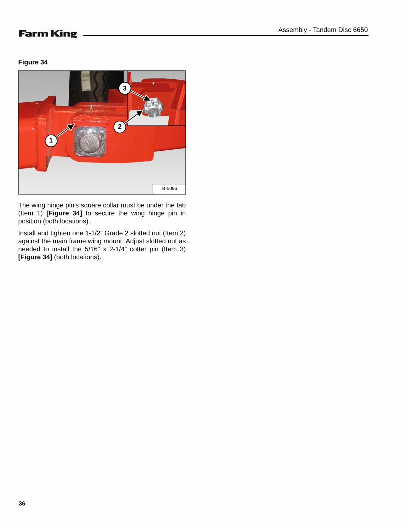
Figure 34
The wing hinge pin’s square collar must be under the tab(Item 1) [Figure 34] to secure the wing hinge pin inposition (both locations).
Install and tighten one 1-1/2” Grade 2 slotted nut (Item 2)against the main frame wing mount. Adjust slotted nut asneeded to install the 5/16” x 2-1/4” cotter pin (Item 3)[Figure 34] (both locations).
B-5096
1
2
3
36
Assembly - Tandem Disc 6650
Installing The Wing Rockshafts
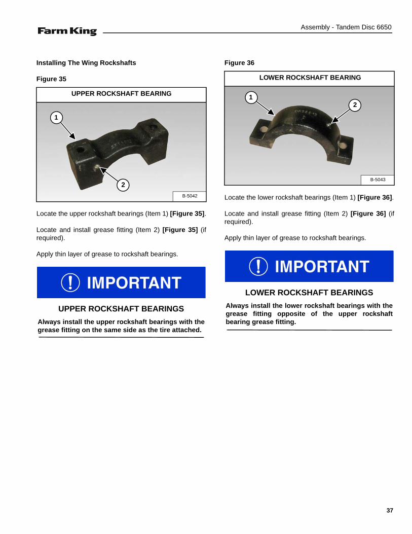
Figure 35
Locate the upper rockshaft bearings (Item 1) [Figure 35].
Locate and install grease fitting (Item 2) [Figure 35] (ifrequired).
Apply thin layer of grease to rockshaft bearings.
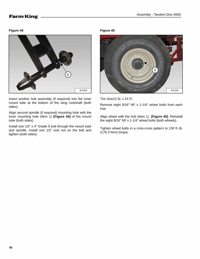
Figure 36
Locate the lower rockshaft bearings (Item 1) [Figure 36].
Locate and install grease fitting (Item 2) [Figure 36] (ifrequired).
Apply thin layer of grease to rockshaft bearings.
B-5042
1
UPPER ROCKSHAFT BEARING
2
UPPER ROCKSHAFT BEARINGS
Always install the upper rockshaft bearings with thegrease fitting on the same side as the tire attached.
B-5043
1
LOWER ROCKSHAFT BEARING
2
LOWER ROCKSHAFT BEARINGS
Always install the lower rockshaft bearings with thegrease fitting opposite of the upper rockshaftbearing grease fitting.
37

Assembly - Tandem Disc 6650
Figure 37
Locate RH wing rockshaft (Item 1). Install a strap (Item 2)[Figure 37] through the RH wing rockshaft.
Connect the straps to an approved lifting device.
Raise and move the RH wing rockshaft to the assemblyarea.
Figure 38
Lower the RH wing rockshaft (Item 1) [Figure 38] downthrough the outer opening in the wing frame.
Figure 39
Rotate the RH wing rockshaft until the rockshaft legs areforward.
Adjust the rockshaft until the two tabs (Item 1) arecentered under the rockshaft bearing mount (Item 2)[Figure 39].
Figure 40
Place one upper rockshaft bearing (Item 1) [Figure 40](grease fitting towards the FRONT) onto the rockshaft.
Raise the rockshaft, aligning the upper rockshaft bearingbetween the two tabs (Item 2) [Figure 40] on therockshaft bearing mount. Continue raising the rockshaftuntil the upper bearing contacts the mount.
Align and install lower rockshaft bearing (Item 3) [Figure40] (grease fitting facing towards the front).
Install two 3/4” x 6-1/2” Grade 5 bolts through the lower,upper rockshaft bearings and mount. Install one 3/4 lockwasher and 3/4” nut (Item 4) [Figure 40] onto each bolt.Do not tighten at this time.
B-5099
1
2
B-5100
1
B-5101
2
1
B-5102
1
2
2
3
4
38

Assembly - Tandem Disc 6650
Figure 41
Place one upper rockshaft bearing (Item 1) [Figure 41](grease fitting towards the front) onto the rockshaft.
Raise the rockshaft, aligning the upper rockshaft bearingbetween the two tabs (Item 2) [Figure 41] on therockshaft bearing mount. Continue raising the rockshaftuntil the upper bearing contacts the mount.
Align and install lower rockshaft bearing (Item 3) [Figure41] (grease fitting facing towards the rear).
Install two 3/4” x 6-1/2” Grade 5 bolts through the lower,upper rockshaft bearings and mount. Install one 3/4 lockwasher and 3/4” nut (Item 4) [Figure 41] onto each bolt.Do not tighten at this time.
Figure 42
Locate two / four eight-bolt hub assemblies with (small)spindles (Item 1) [Figure 42].
Figure 43
Insert one hub assembly into the outer mount tube at thebottom of the wing rockshaft (both sides).
Align spindle mounting hole with the outer mounting hole(Item 1) [Figure 43] of the mount tube (both sides).
Install one 1/2” x 4” Grade 5 bolt through the mount tubeand spindle. Install one 1/2” lock nut on the bolt andtighten (both sides).
B-5154
1
2 2
3
4
B-5103
1
B-5104
1
39
Assembly - Tandem Disc 6650
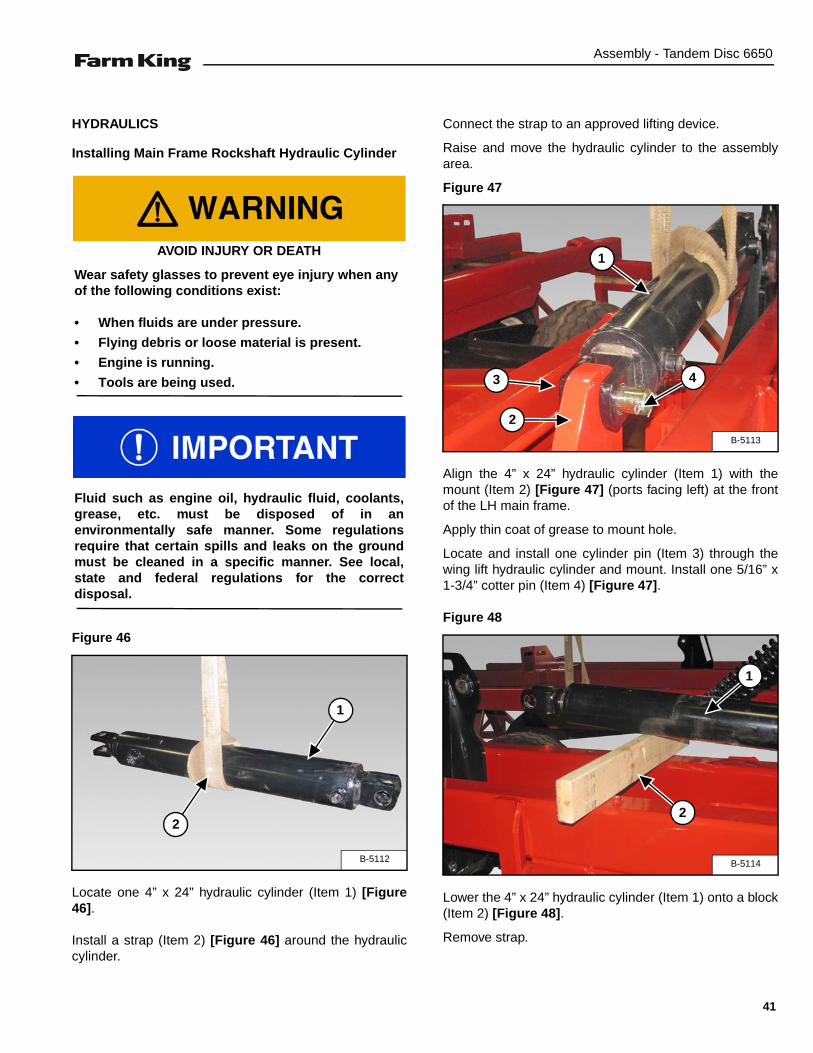
Figure 44
Insert another hub assembly (if required) into the innermount tube at the bottom of the wing rockshaft (bothsides).
Align second spindle (if required) mounting hole with theinner mounting hole (Item 1) [Figure 44] of the mounttube (both sides).
Install one 1/2” x 4” Grade 5 bolt through the mount tubeand spindle. Install one 1/2” lock nut on the bolt andtighten (both sides).
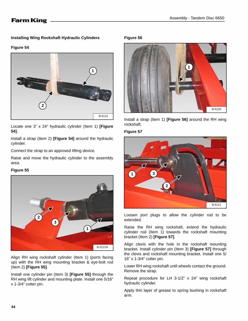
Figure 45
Tire Size12.5L x 15 FI
Remove eight 9/16” NF x 1-1/4” wheel bolts from eachhub.
Align wheel with the hub (Item 1) [Figure 45]. Reinstallthe eight 9/16” NF x 1-1/4” wheel bolts (both wheels).
Tighten wheel bolts in a criss-cross pattern to 130 ft.-lb.(176.3 N•m) torque.
B-5105
1
B-5106
1
40
Assembly - Tandem Disc 6650
HYDRAULICS
Installing Main Frame Rockshaft Hydraulic Cylinder
Figure 46
Locate one 4” x 24” hydraulic cylinder (Item 1) [Figure46].
Install a strap (Item 2) [Figure 46] around the hydrauliccylinder.
Connect the strap to an approved lifting device.
Raise and move the hydraulic cylinder to the assemblyarea.
Figure 47
Align the 4” x 24” hydraulic cylinder (Item 1) with themount (Item 2) [Figure 47] (ports facing left) at the frontof the LH main frame.
Apply thin coat of grease to mount hole.
Locate and install one cylinder pin (Item 3) through thewing lift hydraulic cylinder and mount. Install one 5/16” x1-3/4” cotter pin (Item 4) [Figure 47].
Figure 48
Lower the 4” x 24” hydraulic cylinder (Item 1) onto a block(Item 2) [Figure 48].
Remove strap.
AVOID INJURY OR DEATH
Wear safety glasses to prevent eye injury when anyof the following conditions exist:
• When fluids are under pressure.
• Flying debris or loose material is present.
• Engine is running.
• Tools are being used.
Fluid such as engine oil, hydraulic fluid, coolants,grease, etc. must be disposed of in anenvironmentally safe manner. Some regulationsrequire that certain spills and leaks on the groundmust be cleaned in a specific manner. See local,state and federal regulations for the correctdisposal.
B-5112
1
2
B-5113
1
2
3 4
B-5114
1
2
41

Assembly - Tandem Disc 6650
Figure 49
Install a strap (Item 1) [Figure 49] around the main framerockshaft.
Connect the strap to an approved lifting device.
Figure 50
Loosen port plugs to allow the cylinder rod to beextended.
Raise the main frame rockshaft, extend the hydrauliccylinder rod (Item 1) towards the rockshaft mountingbracket (Item 2) [Figure 50].
Align clevis with the hole in the rockshaft mountingbracket. Install cylinder pin (Item 3) through the clevisand rockshaft mounting bracket. Install one 5/16” x 1-3/4”cotter pin (Item 4) [Figure 50].
Remove block, lower main frame rockshaft until wheelscontact the ground. Remove the strap.
Apply thin layer of grease to spring bushing in rockshaftarm
B-5115
1
B-5116
2
1
34
42

Assembly - Tandem Disc 6650
Installing Wing Lift Cylinders
Figure 51
Locate the two wing lift hydraulic cylinders (Item 1)[Figure 51].
Wing Lift Hydraulic Cylinder Sizes
4” x 36” - Narrow Wing Models (25 ft. to 29-1/2 ft.)
5” x 36” - Wide Wing Models (32 ft. and up)
Install a strap (Item 2) [Figure 51] around the hydrauliccylinder.
Connect the strap to an approved lifting device.
Raise and move the hydraulic cylinder to the assemblyarea.
Figure 52
Align RH wing lift cylinder (Item 1) (ports facing forward)with the right hole on the mounting plate (Item 2) [Figure52] located at the rear of the LH main frame.
Install one cylinder pin (Item 3) [Figure 52] through theRH wing lift cylinder and mounting plate. Install one 5/16”x 1-3/4” cotter pin.
Figure 53
Place a block (Item 1) under the RH wing lift cylinder(Item 2) [Figure 53].
Lower RH wing lift cylinder onto the block and removestrap.
Repeat procedure for LH wing lift cylinder.
B-5117
1
2B-5118
1
3
2
B-5119
1
2
43
Assembly - Tandem Disc 6650
Installing Wing Rockshaft Hydraulic Cylinders
Figure 54
Locate one 3” x 24” hydraulic cylinder (Item 1) [Figure54].
Install a strap (Item 2) [Figure 54] around the hydrauliccylinder.
Connect the strap to an approved lifting device.
Raise and move the hydraulic cylinder to the assemblyarea.
Figure 55
Align RH wing rockshaft cylinder (Item 1) (ports facingup) with the RH wing mounting bracket & eye-bolt rod(Item 2) [Figure 55].
Install one cylinder pin (Item 3) [Figure 55] through theRH wing lift cylinder and mounting plate. Install one 5/16”x 1-3/4” cotter pin.
Figure 56
Install a strap (Item 1) [Figure 56] around the RH wingrockshaft.
Figure 57
Loosen port plugs to allow the cylinder rod to beextended.
Raise the RH wing rockshaft, extend the hydrauliccylinder rod (Item 1) towards the rockshaft mountingbracket (Item 2) [Figure 57].
Align clevis with the hole in the rockshaft mountingbracket. Install cylinder pin (Item 3) [Figure 57] throughthe clevis and rockshaft mounting bracket. Install one 5/16” x 1-3/4” cotter pin.
Lower RH wing rockshaft until wheels contact the ground.Remove the strap.
Repeat procedure for LH 3-1/2” x 24” wing rockshafthydraulic cylinder.
Apply thin layer of grease to spring bushing in rockshaftarm.
B-5112
1
2
B-5121A
1
23
B-5120
1
B-5121
1
2
3
44
Assembly - Tandem Disc 6650
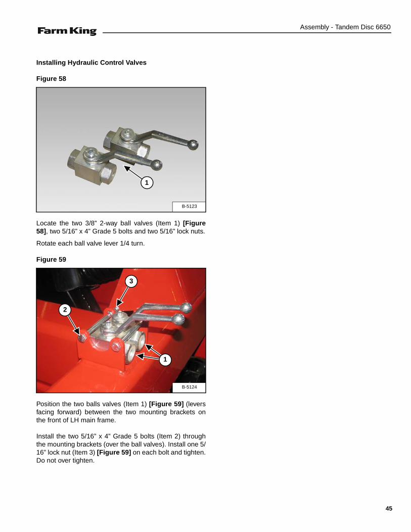
Installing Hydraulic Control Valves
Figure 58
Locate the two 3/8” 2-way ball valves (Item 1) [Figure58], two 5/16” x 4” Grade 5 bolts and two 5/16” lock nuts.
Rotate each ball valve lever 1/4 turn.
Figure 59
Position the two balls valves (Item 1) [Figure 59] (leversfacing forward) between the two mounting brackets onthe front of LH main frame.
Install the two 5/16” x 4” Grade 5 bolts (Item 2) throughthe mounting brackets (over the ball valves). Install one 5/16” lock nut (Item 3) [Figure 59] on each bolt and tighten.Do not over tighten.
B-5123
1
B-5124
1
2
3
45

Assembly - Tandem Disc 6650
Installing Hydraulic Fittings
Control Valve Fittings
Figure 60
Locate two 3/8” male-female swivel fittings (Item 1)[Figure 60].
Apply thread sealant to the two fittings.
NOTE: Do not use teflon tape.
Install the two fittings (facing the rear of the disc) into theball valves.
Wing Rockshaft Cylinder Fittings
Figure 61
Locate four 90° 1/2” swivel street elbows (Item 1) [Figure61].
Apply thread sealant to the two fittings.
Install the rear fitting (Item 2) [Figure 61] and tighten untilthe fitting is facing the center.
Install the front fitting (Item 3) [Figure 61] and tightenuntil the fitting is facing the rear fitting.
Repeat procedure for LH wing rockshaft cylinder.
B-5125
1
B-5126
1 3
2
46
Assembly - Tandem Disc 6650
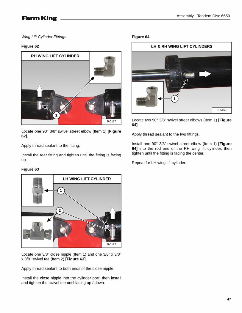
Wing Lift Cylinder Fittings
Figure 62
Locate one 90° 3/8” swivel street elbow (Item 1) [Figure62].
Apply thread sealant to the fitting.
Install the rear fitting and tighten until the fitting is facingup.
Figure 63
Locate one 3/8” close nipple (Item 1) and one 3/8” x 3/8”x 3/8” swivel tee (Item 2) [Figure 63].
Apply thread sealant to both ends of the close nipple.
Install the close nipple into the cylinder port, then installand tighten the swivel tee until facing up / down.
Figure 64
Locate two 90° 3/8” swivel street elbows (Item 1) [Figure64].
Apply thread sealant to the two fittings.
Install one 90° 3/8” swivel street elbow (Item 1) [Figure64] into the rod end of the RH wing lift cylinder, thentighten until the fitting is facing the center.
Repeat for LH wing lift cylinder.
RH WING LIFT CYLINDER
B-5127
1
LH WING LIFT CYLINDER
B-5127
1
2
B-5163
LH & RH WING LIFT CYLINDERS
1
47
Assembly - Tandem Disc 6650
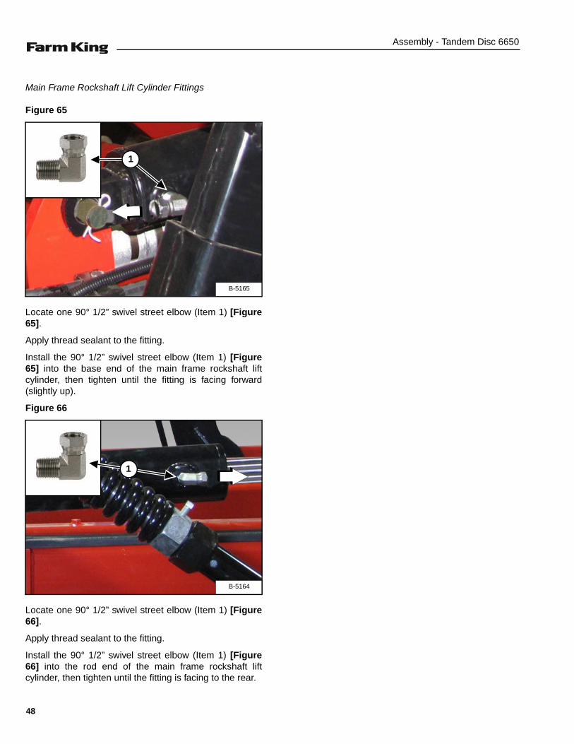
Main Frame Rockshaft Lift Cylinder Fittings
Figure 65
Locate one 90° 1/2” swivel street elbow (Item 1) [Figure65].
Apply thread sealant to the fitting.
Install the 90° 1/2” swivel street elbow (Item 1) [Figure65] into the base end of the main frame rockshaft liftcylinder, then tighten until the fitting is facing forward(slightly up).
Figure 66
Locate one 90° 1/2” swivel street elbow (Item 1) [Figure66].
Apply thread sealant to the fitting.
Install the 90° 1/2” swivel street elbow (Item 1) [Figure66] into the rod end of the main frame rockshaft liftcylinder, then tighten until the fitting is facing to the rear.
B-5165
1
B-5164
1
48
Assembly - Tandem Disc 6650
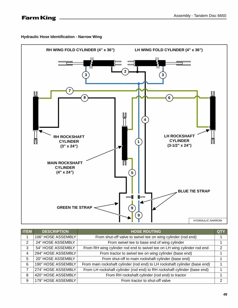
Hydraulic Hose Identification - Narrow Wing
ITEM DESCRIPTION HOSE ROUTING QTY1 106” HOSE ASSEMBLY From shut-off valve to swivel tee on wing cylinder (rod end) 12 24” HOSE ASSEMBLY From swivel tee to base end of wing cylinder 13 54” HOSE ASSEMBLY From RH wing cylinder rod end to swivel tee on LH wing cylinder rod end 24 294” HOSE ASSEMBLY From tractor to swivel tee on wing cylinder (base end) 15 20” HOSE ASSEMBLY From shut-off to main rockshaft cylinder (base end) 16 190” HOSE ASSEMBLY From main rockshaft cylinder (rod end) to LH rockshaft cylinder (base end) 17 274” HOSE ASSEMBLY From LH rockshaft cylinder (rod end) to RH rockshaft cylinder (base end) 18 420” HOSE ASSEMBLY From RH rockshaft cylinder (rod end) to tractor 19 179” HOSE ASSEMBLY From tractor to shut-off valve 2
HYDRAULIC NARROW
3 3
4
2
1
5
6
7
8
9
9GREEN TIE STRAP
BLUE TIE STRAP
MAIN ROCKSHAFT CYLINDER(4” x 24”)
LH WING FOLD CYLINDER (4” x 36”)RH WING FOLD CYLINDER (4” x 36”)
LH ROCKSHAFT CYLINDER
(3-1/2” x 24”)
RH ROCKSHAFT CYLINDER(3” x 24”)
49

Assembly - Tandem Disc 6650
Hydraulic Hose Identification - Wide Wing
ITEM DESCRIPTION HOSE ROUTING QTY1 106” HOSE ASSEMBLY From shut-off valve to swivel tee on wing cylinder (rod end) 12 54” HOSE ASSEMBLY From swivel tee to base end of wing cylinder 13 24” HOSE ASSEMBLY From RH wing cylinder rod end to swivel tee on LH wing cylinder rod end 24 294” HOSE ASSEMBLY From tractor to swivel tee on wing cylinder (base end) 15 20” HOSE ASSEMBLY From shut-off to main rockshaft cylinder (base end) 16 220” HOSE ASSEMBLY From main rockshaft cylinder (rod end) to LH rockshaft cylinder (base end) 17 334” HOSE ASSEMBLY From LH rockshaft cylinder (rod end) to RH rockshaft cylinder (base end) 18 440” HOSE ASSEMBLY From RH rockshaft cylinder (rod end) to tractor 19 179” HOSE ASSEMBLY From tractor to shut-off valve 2
HYDRAULIC WIDE
3 3
4
2
1
5
6
7
8
9
9GREEN TIE STRAP
BLUE TIE STRAP
MAIN ROCKSHAFT CYLINDER(4” x 24”)
LH WING FOLD CYLINDER (5” x 36”)RH WING FOLD CYLINDER (5” x 36”)
LH ROCKSHAFT CYLINDER
(3-1/2” x 24”)
RH ROCKSHAFT CYLINDER(3” x 24”)
50
Assembly - Tandem Disc 6650
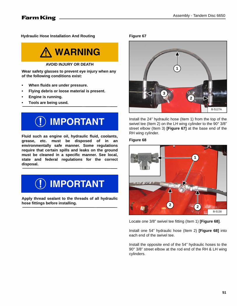
Hydraulic Hose Installation And Routing Figure 67
Install the 24” hydraulic hose (Item 1) from the top of theswivel tee (Item 2) on the LH wing cylinder to the 90° 3/8”street elbow (Item 3) [Figure 67] at the base end of theRH wing cylinder.
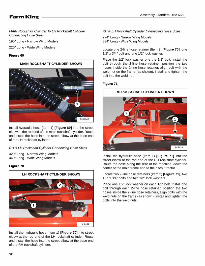
Figure 68
Locate one 3/8” swivel tee fitting (Item 1) [Figure 68].
Install one 54” hydraulic hose (Item 2) [Figure 68] intoeach end of the swivel tee.
Install the opposite end of the 54” hydraulic hoses to the90° 3/8” street elbow at the rod end of the RH & LH wingcylinders.
AVOID INJURY OR DEATH
Wear safety glasses to prevent eye injury when anyof the following conditions exist:
• When fluids are under pressure.
• Flying debris or loose material is present.
• Engine is running.
• Tools are being used.
Fluid such as engine oil, hydraulic fluid, coolants,grease, etc. must be disposed of in anenvironmentally safe manner. Some regulationsrequire that certain spills and leaks on the groundmust be cleaned in a specific manner. See local,state and federal regulations for the correctdisposal.
Apply thread sealant to the threads of all hydraulichose fittings before installing.
B-5127A
1
23
B-5130
1
22
51
Assembly - Tandem Disc 6650
MAIN Rockshaft Cylinder To LH Rockshaft Cylinder Connecting Hose Sizes
190” Long - Narrow Wing Models
220” Long - Wide Wing Models
Figure 69
Install hydraulic hose (Item 1) [Figure 69] into the streetelbow at the rod end of the main rockshaft cylinder. Routeand install the hose into the street elbow at the base endof the LH rockshaft cylinder.
RH & LH Rockshaft Cylinder Connecting Hose Sizes
420” Long - Narrow Wing Models440” Long - Wide Wing Models
Figure 70
Install the hydraulic hose (Item 1) [Figure 70] into streetelbow at the rod end of the LH rockshaft cylinder. Routeand install the hose into the street elbow at the base endof the RH rockshaft cylinder.
RH & LH Rockshaft Cylinder Connecting Hose Sizes
274” Long - Narrow Wing Models334” Long - Wide Wing Models
Locate one 2-line hose retainer (Item 2) [Figure 70], one1/2” x 3/4” bolt and one 1/2” lock washer.
Place the 1/2” lock washer one the 1/2” bolt. Install thebolt through the 2-line hose retainer, position the twohoses inside the 2-line hose retainer, align bolt with theweld nut on the frame (as shown), install and tighten thebolt into the weld nut.
Figure 71
Install the hydraulic hose (Item 1) [Figure 71] into thestreet elbow at the rod end of the RH rockshaft cylinder.Route the hose along the rear of the machine, down thecenter of the main frame and to the hitch / tractor.
Locate two 2-line hose retainers (Item 2) [Figure 71], two1/2” x 3/4” bolts and two 1/2” lock washers.
Place one 1/2” lock washer on each 1/2” bolt. Install onebolt through each 2-line hose retainer, position the twohoses inside the 2-line hose retainers, align bolts with theweld nuts on the frame (as shown), install and tighten thebolts into the weld nuts.
B-5164A
1
MAIN ROCKSHAFT CYLINDER SHOWN
B-5131
1
LH ROCKSHAFT CYLINDER SHOWN
2
B-5129
1
RH ROCKSHAFT CYLINDER SHOWN
2
52

Assembly - Tandem Disc 6650
Figure 72
Install the 294” hydraulic hose (Item 1) [Figure 72] intothe bottom side of the swivel tee on the LH wing cylinder.Route the hose down the center of the machines frameand to the hitch / tractor.
Install the 106” hydraulic hose (Item 2) [Figure 72] intothe swivel tee (connected to the rod ends of the LH & RHwing cylinders). Route the hose down the center of themachine frame to the shut-off valves.
Locate one 4-line hose retainer (Item 3) [Figure 72], one1/2” x 3/4” bolt and one 1/2” lock washer.
Place the 1/2” lock washer on the 1/2” bolt. Install the boltthrough the 4-line hose retainer, position the four hosesinside the 4-line hose retainer, align bolt with the weld nuton the frame (as shown), install and tighten the bolt intothe weld nut.
Figure 73
Install the 106” hydraulic hose (Item 1) [Figure 73] (fromswivel tee in [Figure 72]) into the LH shut-off valve.
Install the one 179” hydraulic hose (Item 2) [Figure 73]into the front side of the LH shut-off valve. Route the hoseto the hitch / tractor (Blue tie strap).
Install the one 179” hydraulic hose (Item 3) [Figure 73]into the front side of the RH shut-off valve. Route thehose to the hitch / tractor (Green tie strap).
B-5132
2
1
3
B-5134A
1
23
53
Assembly - Tandem Disc 6650
Figure 74
Install the 20” hydraulic hose (Item 1) [Figure 74] into thestreet elbow at the base end of the main rockshaftcylinder. Route and install the hose to the RH shut-offvalve (Item 2) [Figure 74].
Locate one 4-line hose retainer (Item 3) [Figure 74], one1/2” x 3/4” bolt and one 1/2” lock washer.
Place the 1/2” lock washer on the 1/2” bolt. Install the boltthrough the 4-line hose retainer, position the three hosesinside the 4-line hose retainer, align bolt with the weld nuton the frame (as shown), install and tighten the bolt intothe weld nut.
Locate the remaining 2 and 4-line hose retainers, 1/2” x3/4” bolts and 1/2” lock washers. Install the correct hoseretainers at all weld nut locations to secure all hydraulichoses to the machines frame.
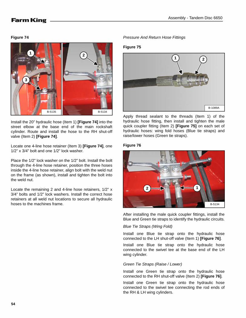
Pressure And Return Hose Fittings
Figure 75
Apply thread sealant to the threads (Item 1) of thehydraulic hose fitting, then install and tighten the malequick coupler fitting (Item 2) [Figure 75] on each set ofhydraulic hoses: wing fold hoses (Blue tie straps) andraise/lower hoses (Green tie straps).
Figure 76
After installing the male quick coupler fittings, install theBlue and Green tie straps to identify the hydraulic circuits.
Blue Tie Straps (Wing Fold)
Install one Blue tie strap onto the hydraulic hoseconnected to the LH shut-off valve (Item 1) [Figure 76].
Install one Blue tie strap onto the hydraulic hoseconnected to the swivel tee at the base end of the LHwing cylinder.
Green Tie Straps (Raise / Lower)
Install one Green tie strap onto the hydraulic hoseconnected to the RH shut-off valve (Item 2) [Figure 76].
Install one Green tie strap onto the hydraulic hoseconnected to the swivel tee connecting the rod ends ofthe RH & LH wing cylinders.
B-5134B-5135
1
3
2
B-1089A
21
B-5134
12
54
Assembly - Tandem Disc 6650
Enter the tractor, start the engine and move the tractor infront of the tandem disc hitch.
Engage parking brake and exit the tractor.
Connect the hydraulic hoses to the tractor’s auxiliaryhydraulics.
Figure 77
Open the two shut-off valves [Figure 77].
Enter the tractor and engage tractor auxiliary hydraulics.Using the tractor’s auxiliary controls, cycle the hydrauliccylinders on the tandem disc to remove all air from thesystem.
Figure 78
Fully extend the RH & LH wing cylinders.
Turn tractor engine off and exit the tractor.
Align the clevis (Item 1) with the mounting bracket (Item2) [Figure 78] on the RH & LH wings.
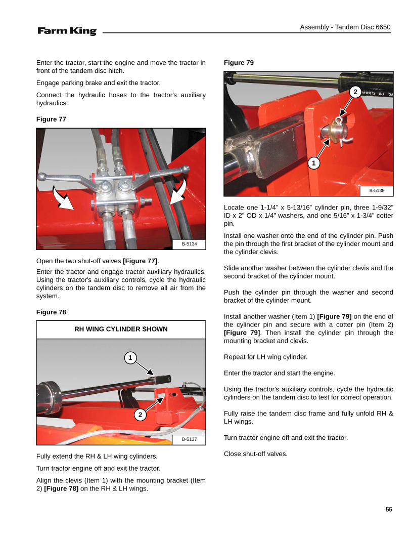
Figure 79
Locate one 1-1/4” x 5-13/16” cylinder pin, three 1-9/32”ID x 2” OD x 1/4” washers, and one 5/16” x 1-3/4” cotterpin.
Install one washer onto the end of the cylinder pin. Pushthe pin through the first bracket of the cylinder mount andthe cylinder clevis.
Slide another washer between the cylinder clevis and thesecond bracket of the cylinder mount.
Push the cylinder pin through the washer and secondbracket of the cylinder mount.
Install another washer (Item 1) [Figure 79] on the end ofthe cylinder pin and secure with a cotter pin (Item 2)[Figure 79]. Then install the cylinder pin through themounting bracket and clevis.
Repeat for LH wing cylinder.
Enter the tractor and start the engine.
Using the tractor’s auxiliary controls, cycle the hydrauliccylinders on the tandem disc to test for correct operation.
Fully raise the tandem disc frame and fully unfold RH &LH wings.
Turn tractor engine off and exit the tractor.
Close shut-off valves.
B-5134
B-5137
1
RH WING CYLINDER SHOWN
2
B-5139
1
2
55

Assembly - Tandem Disc 6650
PURGING / REPHASING HYDRAULIC SYSTEM
Purging Hydraulic System
Following assembly and prior to placing the tandem discinto field service, it is important the series depth controlcylinders be purged of air that has been trapped in thesystem.
Use the following procedure to purge trapped air from thehydraulic system:
1. Connect the tandem disc hydraulics to tractor andremove all depth control stops.
2. Raise tandem disc to extend lift cylinders fully andhold hydraulic lever in the UP position for (3) threeminutes.
3. Lower tandem disc to retract lift cylinders fully.
NOTE: All lift cylinders may not fully retract.
4. Raise tandem disc again and hold hydraulic lever inthe UP position for another (3) three minutes.
Rephasing Hydraulic System
Following the initial purging of the series hydraulicsystem, it is recommended practice to rephase the depthcylinders several times each day by holding hydrauliclever in the UP position for (5-10) five to ten seconds.This can be normally done when disc is raised to make aturn at the end of the field.Failure to purge hydraulic system of air or rephase
depth control cylinders, could result in unevenworking depth across the width of the machine, asone or more cylinders may creep, “bounce” or moveerratically.
Hydraulic pressure in the tandem disc system mustbe relieved at the end of the day and prior touncoupling from tractor. Always lower tandem discwith the tractor running, failure to do so will result inair getting back into the rephasing system.
56
Assembly - Tandem Disc 6650
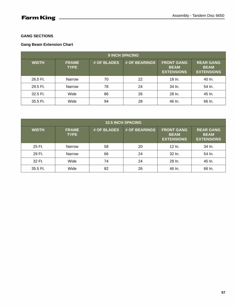
GANG SECTIONS
Gang Beam Extension Chart
9 INCH SPACING
WIDTH FRAMETYPE
# OF BLADES # OF BEARINGS FRONT GANG BEAM
EXTENSIONS
REAR GANG BEAM
EXTENSIONS
26.5 Ft. Narrow 70 22 18 In. 40 In.
29.5 Ft. Narrow 78 24 34 In. 54 In.
32.5 Ft. Wide 86 26 28 In. 45 In.
35.5 Ft. Wide 94 28 46 In. 66 In.
10.5 INCH SPACING
WIDTH FRAMETYPE
# OF BLADES # OF BEARINGS FRONT GANG BEAM
EXTENSIONS
REAR GANG BEAM
EXTENSIONS
25 Ft. Narrow 58 20 12 In. 34 In.
29 Ft. Narrow 66 24 32 In. 54 In.
32 Ft. Wide 74 24 28 In. 45 In.
35.5 Ft. Wide 82 26 46 In. 66 In.
57
Assembly - Tandem Disc 6650
General Information
Identify the front / rear and left / right gang sections.
For additional gang section information. (See “GANGPATTERNS” on page 76.)
• DO NOT permit bystanders to be in the work areawhen unloading and assembling the tandem disccomponents.
• DO NOT work under suspended parts.
• Keep away from moving parts.
• Always use lifting devices / vehicles, chains orstraps of adequate size and strength whenunloading and assembling the tandem disccomponents.
AVOID INJURY OR DEATH
Wear safety glasses to prevent eye injury when anyof the following conditions exist:
• When fluids are under pressure.
• Flying debris or loose material is present.
• Engine is running.
• Tools are being used.
AVOID INJURY OR DEATHKeep fingers and hands out of pinch points whenassembling the equipment.
Always wear protective gloves when installing,removing or servicing gang sections to help preventinjury from cutting edges of blades.
58

Assembly - Tandem Disc 6650
Installing The Gang Extensions
Figure 80
Locate the two short and two long gang extensions (Item1) [Figure 80], eight 3/4” x 3” bolts, eight 3/4” lockwashers and eight 3/4” nuts.
Align the extension with the main frame mounting flangeon the wing. Install four 3/4” x 3” bolts (Item 2) [Figure 7]through the two flanges.
Install one 3/4” lock washer and 3/4” nut onto each bolt.Tighten bolts and nuts.
Repeat for remaining gang extensions.
NOTE: Short gang extensions in front and long gangextensions in the rear.
Figure 81
Visually check that the gang extension (Item 1) [Figure81] is aligned with the main frame (left / right alignment).
NOTE: Gang extensions must be within ±1/4 inchfront to back when aligning with the mainframe.
Add shims as needed to align the gang extension. (See“Shimming Gang Extensions” on page 60.)
Repeat for remaining gang extensions.
Figure 82
Measure the distance (Item 1) from the ground to thebottom edge of the main frame. Then measure thedistance (Item 2) [Figure 82] from the ground to thebottom edge of the gang extension.
NOTE: Gang extensions must be within ±1/4 inch ofthe distance from the ground to bottom of themain frame.
Add shims as needed to level the gang extension. (See“Shimming Gang Extensions” on page 60.)
Repeat for remaining gang extensions.
B-5142
1
2
B-5145
1
B-5147
12
59

Assembly - Tandem Disc 6650
Shimming Gang Extensions
Figure 83
Locate 1” x 1” gang extension shims (Item 1) [Figure 83].
Install shims (Item 1) [Figure 83] between the flanges incorrect locations to align or level gang extensions withthe main frame.
Tighten bolts and nuts (holding shims flush with flanges).
Visually inspect and measure the gang extension.
Repeat shimming procedure until the gang extension isaligned / leveled with the main frame within ±1/4 inch.
Remove scraper assemblies and bundling tie bars fromgang sections. The scraper assembly bundled with eachgang section will be assembled / installed together.
NOTE: The 5/8” x 2” U-bolts used to bundle scraperassemblies must be saved to assemblescraper bar to gang beam later.
B-5146
1
1
Always keep each gang section and correspondingscraper assembly together.
60
Assembly - Tandem Disc 6650
Installing The Gang Sections
Installing The Inside Gang Sections
NOTE: The following procedure shows installing theleft front gang sections. The procedure iscorrect for all gang sections.
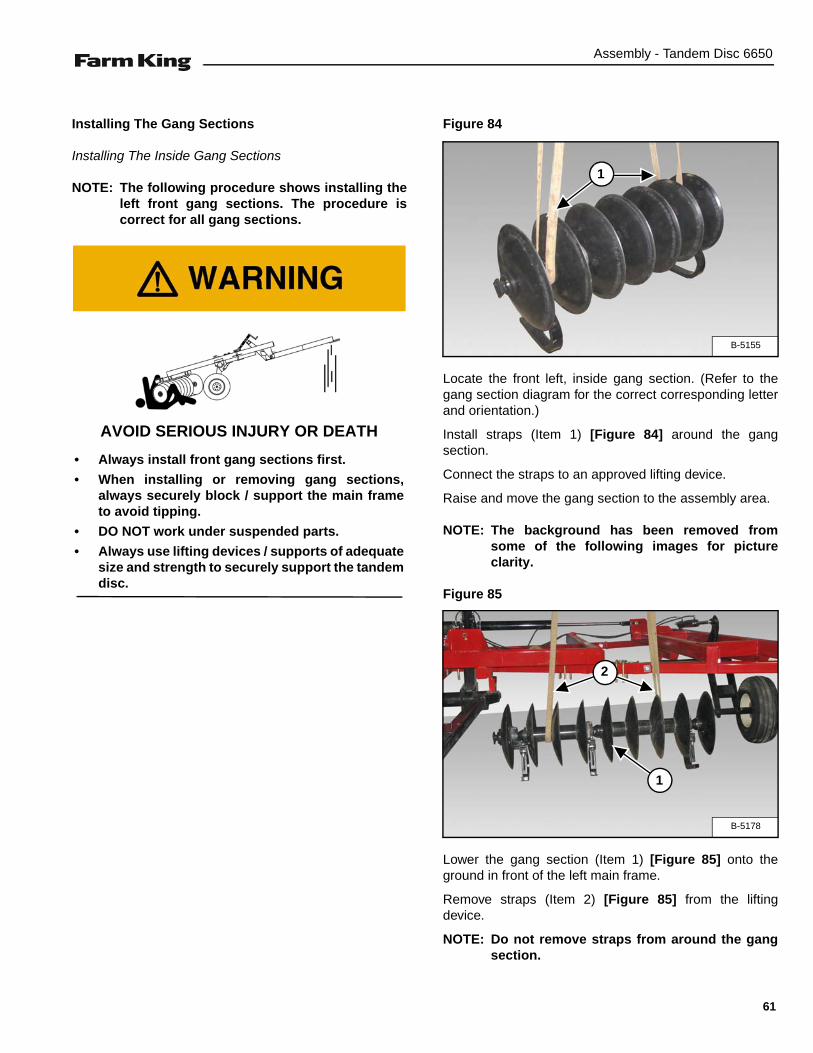
Figure 84
Locate the front left, inside gang section. (Refer to thegang section diagram for the correct corresponding letterand orientation.)
Install straps (Item 1) [Figure 84] around the gangsection.
Connect the straps to an approved lifting device.
Raise and move the gang section to the assembly area.
NOTE: The background has been removed fromsome of the following images for pictureclarity.
Figure 85
Lower the gang section (Item 1) [Figure 85] onto theground in front of the left main frame.
Remove straps (Item 2) [Figure 85] from the liftingdevice.
NOTE: Do not remove straps from around the gangsection.
AVOID SERIOUS INJURY OR DEATH
• Always install front gang sections first.
• When installing or removing gang sections,always securely block / support the main frameto avoid tipping.
• DO NOT work under suspended parts.
• Always use lifting devices / supports of adequatesize and strength to securely support the tandemdisc.
B-5155
1
B-5178
1
2
61
Assembly - Tandem Disc 6650
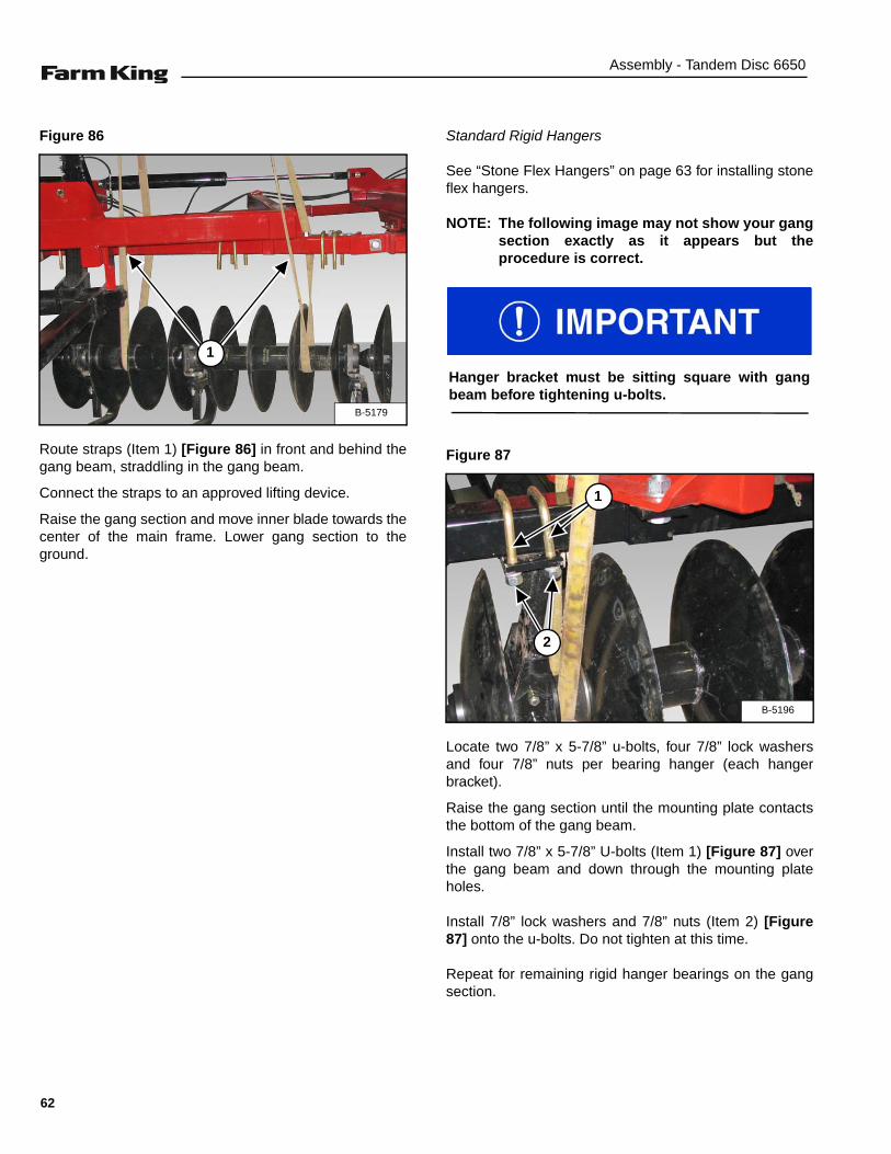
Figure 86
Route straps (Item 1) [Figure 86] in front and behind thegang beam, straddling in the gang beam.
Connect the straps to an approved lifting device.
Raise the gang section and move inner blade towards thecenter of the main frame. Lower gang section to theground.
Standard Rigid Hangers
See “Stone Flex Hangers” on page 63 for installing stoneflex hangers.
NOTE: The following image may not show your gangsection exactly as it appears but theprocedure is correct.
Figure 87
Locate two 7/8” x 5-7/8” u-bolts, four 7/8” lock washersand four 7/8” nuts per bearing hanger (each hangerbracket).
Raise the gang section until the mounting plate contactsthe bottom of the gang beam.
Install two 7/8” x 5-7/8” U-bolts (Item 1) [Figure 87] overthe gang beam and down through the mounting plateholes.
Install 7/8” lock washers and 7/8” nuts (Item 2) [Figure87] onto the u-bolts. Do not tighten at this time.
Repeat for remaining rigid hanger bearings on the gangsection.
B-5179
1
Hanger bracket must be sitting square with gangbeam before tightening u-bolts.
B-5196
1
2
62
Assembly - Tandem Disc 6650
Stone Flex Hangers
NOTE: The following images may not show yourgang section exactly as it appears but theprocedure is correct.
Figure 88
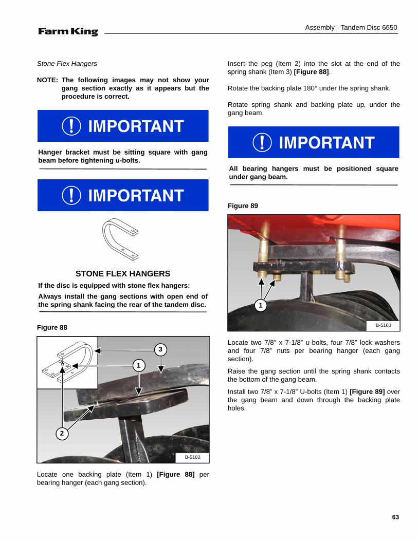
Locate one backing plate (Item 1) [Figure 88] perbearing hanger (each gang section).
Insert the peg (Item 2) into the slot at the end of thespring shank (Item 3) [Figure 88].
Rotate the backing plate 180° under the spring shank.
Rotate spring shank and backing plate up, under thegang beam.
Figure 89
Locate two 7/8” x 7-1/8” u-bolts, four 7/8” lock washersand four 7/8” nuts per bearing hanger (each gangsection).
Raise the gang section until the spring shank contactsthe bottom of the gang beam.
Install two 7/8” x 7-1/8” U-bolts (Item 1) [Figure 89] overthe gang beam and down through the backing plateholes.
Hanger bracket must be sitting square with gangbeam before tightening u-bolts.
STONE FLEX HANGERSIf the disc is equipped with stone flex hangers:
Always install the gang sections with open end ofthe spring shank facing the rear of the tandem disc.
B-5182
2
1
3
All bearing hangers must be positioned squareunder gang beam.
B-5160
1
63

Assembly - Tandem Disc 6650
Figure 90
Install 7/8” lock washers (Item 1) and 7/8” nuts (Item 2)[Figure 90] onto the u-bolts. Do not tighten at this time.
Repeat [Figure 88] - [Figure 90] for remaining hangerbearings on the gang section.
Positioning Front Left Inside Gang Section
Figure 91
Locate and mark the center of the main frame.
Position the front inside gang section, so that the leadingedge of inside blade is approximately 2-1/2” (63.5 mm)past center of main frame [Figure 91].
Tighten inside hanger bearing u-bolts, then tightenremaining hanger bearing u-bolts on the inside gangsection.
B-5161
21
LEFT FRONT GANG
CENTER OF MAIN FRAME
2-1/2”
(63.5 mm)
Always tighten inside hanger bearing u-bolts first,while maintaining the 2-1/2” (63.5 mm) spacing pastcenter of main frame. Tighten all bearing hanger u-bolts to 430 ft.-lb. (583 N•m) torque.
Verify that all bearing hangers are positioned squareunder gang beam before tightening the u-bolts.
64
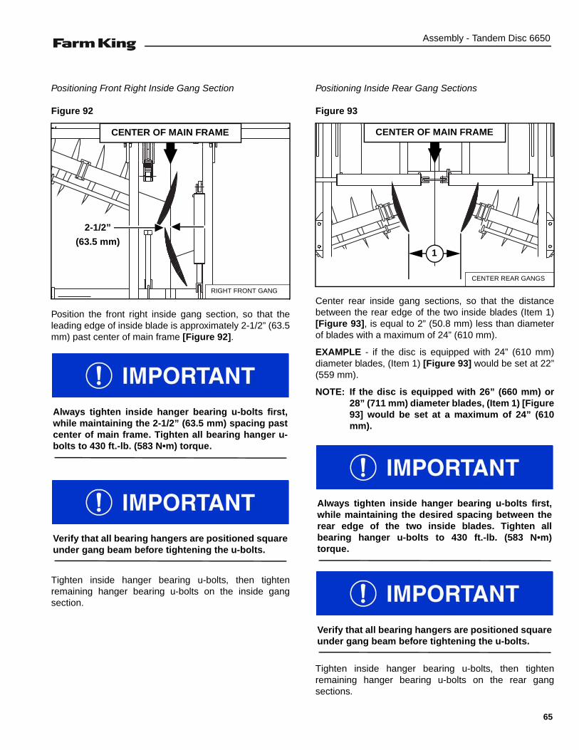
Assembly - Tandem Disc 6650
Positioning Front Right Inside Gang Section
Figure 92
Position the front right inside gang section, so that theleading edge of inside blade is approximately 2-1/2” (63.5mm) past center of main frame [Figure 92].
Tighten inside hanger bearing u-bolts, then tightenremaining hanger bearing u-bolts on the inside gangsection.
Positioning Inside Rear Gang Sections
Figure 93
Center rear inside gang sections, so that the distancebetween the rear edge of the two inside blades (Item 1)[Figure 93], is equal to 2” (50.8 mm) less than diameterof blades with a maximum of 24” (610 mm).
EXAMPLE - if the disc is equipped with 24” (610 mm)diameter blades, (Item 1) [Figure 93] would be set at 22”(559 mm).
NOTE: If the disc is equipped with 26” (660 mm) or28” (711 mm) diameter blades, (Item 1) [Figure93] would be set at a maximum of 24” (610mm).
Tighten inside hanger bearing u-bolts, then tightenremaining hanger bearing u-bolts on the rear gangsections.
RIGHT FRONT GANG
CENTER OF MAIN FRAME
2-1/2”
(63.5 mm)
Always tighten inside hanger bearing u-bolts first,while maintaining the 2-1/2” (63.5 mm) spacing pastcenter of main frame. Tighten all bearing hanger u-bolts to 430 ft.-lb. (583 N•m) torque.
Verify that all bearing hangers are positioned squareunder gang beam before tightening the u-bolts.
CENTER REAR GANGS
CENTER OF MAIN FRAME
1
Always tighten inside hanger bearing u-bolts first,while maintaining the desired spacing between therear edge of the two inside blades. Tighten allbearing hanger u-bolts to 430 ft.-lb. (583 N•m)torque.
Verify that all bearing hangers are positioned squareunder gang beam before tightening the u-bolts.
65

Assembly - Tandem Disc 6650
Outside Gang Section Installation
NOTE: The following procedure shows installing theleft front outside gang section. The procedureis the same for all outside gang sections.
Figure 94
Locate the front left, outside gang section. (Refer to thegang section diagram for the correct corresponding letterand orientation.)
Install straps (Item 1) [Figure 94] around the gangsection.
Connect the straps to an approved lifting device.
Raise and move the gang section to the assembly area.
Lower the gang section onto the ground in front of the leftwing frame.
Remove straps from the lifting device.
NOTE: Do not remove straps from around the gangsection.
Route straps (Item 1) [Figure 94] in front and behind thewing gang beam, straddling the wing gang beam.
Connect the straps to an approved lifting device.
NOTE: When adjusting / aligning gang sections,always maintain the designated blade spacingbetween gang sections.
Raise the gang section and move inner blade towards theinside gang section (approximate blade spacingdistance). Lower gang section to the ground.
Standard Rigid Hangers
For installing stone flex hangers, See “Stone FlexHangers” on page 63. Also on next page.
NOTE: The following image may not show your gangsection exactly as it appears but theprocedure is correct.
Figure 95
Locate two 7/8” x 5-7/8” u-bolts, four 7/8” lock washersand four 7/8” nuts per bearing hanger (each hangerbracket).
Raise the gang section until the mounting plate contactsthe bottom of the gang beam.
Install two 7/8” x 5-7/8” U-bolts (Item 1) [Figure 95] overthe gang beam and down through the mounting plateholes.
Install 7/8” lock washers (Item 1) and 7/8” nuts (Item 2)[Figure 95] onto the u-bolts. Do not tighten at this time.
Repeat for remaining rigid hanger bearings on the gangsection.
B-5180
1
Hanger bracket must be sitting square with gangbeam before tightening u-bolts.
B-5196
1
2
66

Assembly - Tandem Disc 6650
Stone Flex Hangers
Figure 96
Locate one backing plate (Item 1) [Figure 96] perbearing hanger (each gang section).
Insert the peg (Item 2) into the slot at the end of thespring shank (Item 3) [Figure 96].
Rotate the backing plate 180° under the spring shank.
Rotate spring shank and backing plate up, under thegang beam.
Figure 97
Raise the gang section until the spring shank contactsthe bottom of the gang beam.
Install two 7/8” x 7-1/8” U-bolts (Item 1) [Figure 97] overthe gang beam and down through the backing plateholes.
Figure 98
Install 7/8” lock washers (Item 1) and 7/8” nuts (Item 2)[Figure 98] onto the u-bolts. Do not tighten at this time.
Repeat [Figure 96] - [Figure 98] for remaining hangerbearings on the gang section.
B-5182
2
1
3
B-5160
1
B-5161
21
67
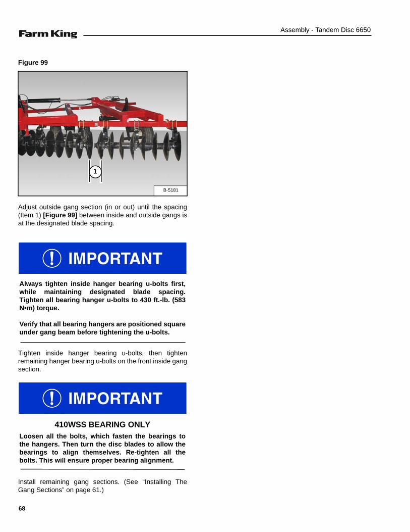
Assembly - Tandem Disc 6650
Figure 99
Adjust outside gang section (in or out) until the spacing(Item 1) [Figure 99] between inside and outside gangs isat the designated blade spacing.
Tighten inside hanger bearing u-bolts, then tightenremaining hanger bearing u-bolts on the front inside gangsection.
Install remaining gang sections. (See “Installing TheGang Sections” on page 61.)
B-5181
1
Always tighten inside hanger bearing u-bolts first,while maintaining designated blade spacing.Tighten all bearing hanger u-bolts to 430 ft.-lb. (583N•m) torque.
Verify that all bearing hangers are positioned squareunder gang beam before tightening the u-bolts.
410WSS BEARING ONLYLoosen all the bolts, which fasten the bearings tothe hangers. Then turn the disc blades to allow thebearings to align themselves. Re-tighten all thebolts. This will ensure proper bearing alignment.
68

Assembly - Tandem Disc 6650
Installing The Scraper Bar And Scrapers
Standard Scraper Bar Mounting
Figure 100
Install one 3/4” x 6-7/8” u-bolt (Item 1) over the gangbeam and down through the scraper bar mount (Item 2).Install two 3/4” lock washers and two 3/4” nuts (Item 3)[Figure 100] on the u-bolt. Do not tighten at this time.
Continue installing the remaining scraper bar mounts asrequired.
NOTE: Mount (Item 2) [Figure 100] is positioned soscraper bar is located at rear of gangs.
NOTE: Each disc model is supplied with one scrapermount bracket per hanger.
Offset scraper mount brackets are providedfor tight locations where the standard scraperbracket won't fit. There are four offsetbrackets supplied per machine. If required,use offset brackets as standard scraperbrackets.
In general, locate the outside bracket for eachscraper bar as close to the end as possible.Try to avoid having the outer brackets locatedbehind two scrapers. Locate the innerbrackets next to bearing hangers.
Offset Scraper Bar Mounting
Figure 101
Install one 3/4” x 6-7/8” u-bolt (Item 1) over the gangbeam and up through the scraper bar mount (Item 2).Install two 3/4” lock washers and two 3/4” nuts (Item 3)[Figure 101] on the u-bolt. Do not tighten at this time.
Continue installing the remaining scraper bar mounts asrequired.
NOTE: Mount (Item 2) [Figure 101] is positioned soscraper bar is located at rear of gangs.
Locate each gang section, corresponding scraperassemblies and hardware that were removed beforeinstalling gang sections.
STD SCRAPER MOUNT
GANG BEAM2
1
3
OFFSET SCRAPER MOUNT
GANG BEAM
1
23
Each gang section and corresponding scraperassembly must be installed together.
69
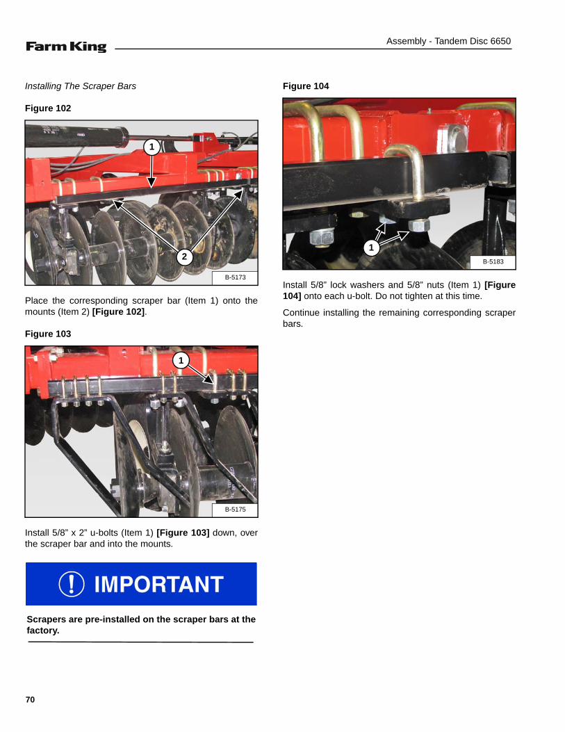
Assembly - Tandem Disc 6650
Installing The Scraper Bars
Figure 102
Place the corresponding scraper bar (Item 1) onto themounts (Item 2) [Figure 102].
Figure 103
Install 5/8” x 2” u-bolts (Item 1) [Figure 103] down, overthe scraper bar and into the mounts.
Figure 104
Install 5/8” lock washers and 5/8” nuts (Item 1) [Figure104] onto each u-bolt. Do not tighten at this time.
Continue installing the remaining corresponding scraperbars.
B-5173
1
2
B-5175
1
Scrapers are pre-installed on the scraper bars at thefactory.
B-5183
1
70

Assembly - Tandem Disc 6650
Standard Scrapers
Figure 105
Front LH / rear RH standard scraper (Item 1) and front LH/ rear RH standard 90° scraper (Item 2) [Figure 105].
NOTE: Front RH and rear LH scrapers are opposite ofthe scrapers shown in [Figure 105].
Wide Pan Scrapers
Figure 106
Front LH / rear RH wide pan scraper (Item 1) and frontLH / rear RH wide pan 90° scraper (Item 2) [Figure 106].
NOTE: Front RH and rear LH scrapers are opposite ofthe scrapers shown in [Figure 106].
Installing Hydraulic Hose Bracket
Figure 107
Locate the hydraulic hose bracket (Item 1) [Figure 107],two 1/2” x 4-9/16” u-bolts, four 1/2” lock washers and four1/2” nuts.
Align the hydraulic hose bracket on the same side as thehitch jack. Position the bracket on tube approximately 16”from the end of the tube.
Install the two 1/2” x 4-9/16” u-bolts around the hitch andthrough the hydraulic hose bracket (Item 1). Install thefour 1/2” lock washers and 1/2” nuts (Item 2) [Figure 107]on the u-bolts. Tighten nuts to secure the hydraulic hosebracket to the hitch.
B-5184
1
2
B-5185
1
2
B-5197
1
2
71
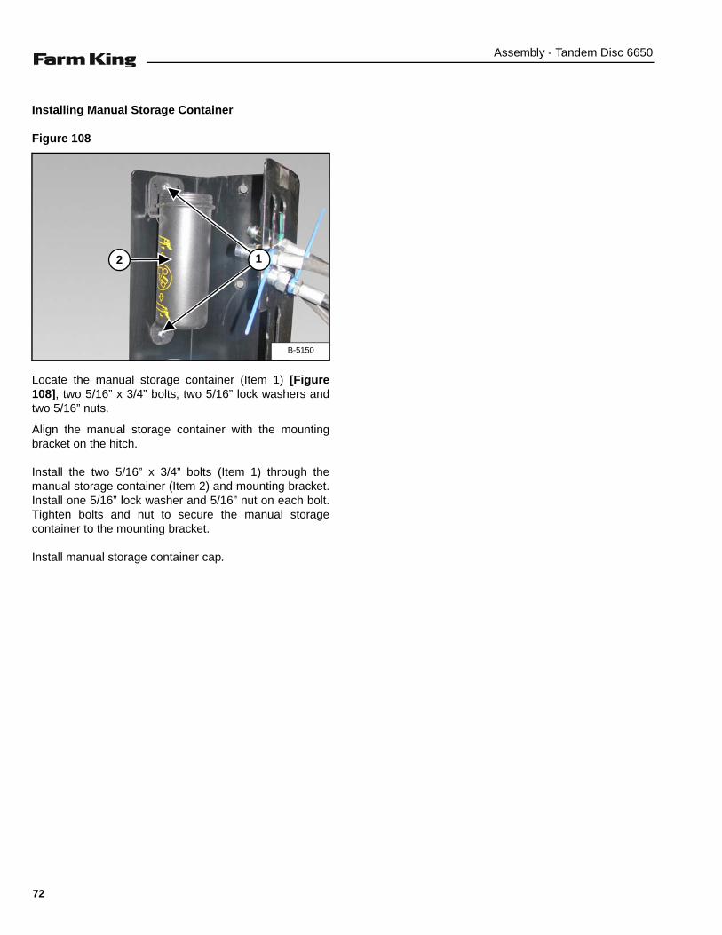
Assembly - Tandem Disc 6650
Installing Manual Storage Container
Figure 108
Locate the manual storage container (Item 1) [Figure108], two 5/16” x 3/4” bolts, two 5/16” lock washers andtwo 5/16” nuts.
Align the manual storage container with the mountingbracket on the hitch.
Install the two 5/16” x 3/4” bolts (Item 1) through themanual storage container (Item 2) and mounting bracket.Install one 5/16” lock washer and 5/16” nut on each bolt.Tighten bolts and nut to secure the manual storagecontainer to the mounting bracket.
Install manual storage container cap.
B-5150
2 1
72

Assembly - Tandem Disc 6650
LIGHT KIT
Installation
Figure 109
Locate one light bracket (Item 1) [Figure 109].
Install a strap (Item 2) [Figure 109] around the lightbracket (twice).
Connect the strap to an approved lifting device.
Raise and move the light bracket to the assembly area.
Figure 110
Locate one backing plate (Item 1) [Figure 110], two 1/2”x 8-1/2” bolts, two 1/2” lock washers and two 1/2” nuts.
Position the light bracket towards the rear on the outsideframe of the RH center frame. Lower the light bracketinside the frame, align the backing plate and install thetwo 1/2” bolts (Item 2) [Figure 110], through the backingplate and light bracket. Install 1/2” lock washers and nutson the bolts. Visually inspect that the light bracket issquare (plumb) with the main frame.
NOTE: Verify that the light bracket is positioned in alocation where the RH wing will not damagethe light bracket when folded.
Tighten the 1/2” bolts and nuts to secure the light bracketto the main frame.
Repeat for installing opposite light bracket.
Figure 111
Locate one amber light (Item 1) [Figure 111].
Install the amber light assembly into the lower slot of thelight bracket. Position the amber light facing front / rear ofthe machine.
Tighten nut (Item 2) [Figure 111].
Repeat for opposite amber light assembly.
B-5186
2
1
B-5187
1 2
B-5188
1
2
73

Assembly - Tandem Disc 6650
Figure 112
Locate one red light assembly (Item 1) [Figure 112].
Install the red light assembly into the upper slot of thelight bracket. Position the red light facing the rear of themachine.
Tighten nut (Item 2) [Figure 112].
Repeat for opposite red light assembly.
Figure 113
Locate the wire harness (Item 1) [Figure 113].
Connect the wire harness to each of the amber and redlights (both sides).
NOTE: Harness plugs are marked with either LH orRH. Make sure lamp plugs are connected tothe correct side.
Route the wire harness down the center of the mainframe (along hydraulic hoses) and the front of the hitch.
Using cable ties, secure wire harness to the light bracketsand hydraulic hoses.
Figure 114
Install storage cup below manual holder using one 1/4” x5/8” bolt, 1/4” lockwasher, and 1/4” nut.
Install the wire harness 7-pin connector in the storagecup (Item 1) [Figure 114] on the hydraulic hose bracket.
B-5189
1
2
B-5190
1
B-5151
1
74

Assembly - Tandem Disc 6650
DEPTH STOPS
Figure 115
Locate the two sets of depth stops [Figure 115].
Figure 116
Store unused depth stops on the rod (Item 1) [Figure116] just behind the front main frame (center).
Figure 117
Install depth stops (Item 1) [Figure 117] on the mainrockshaft cylinder as needed for transport or to maintainworking depth.
B-5176
B-5177
1
B-5191
1
ALL depth stops must be installed on main framerockshaft cylinder when transporting disc.
The depth stops will have a total length of 17 inches
75
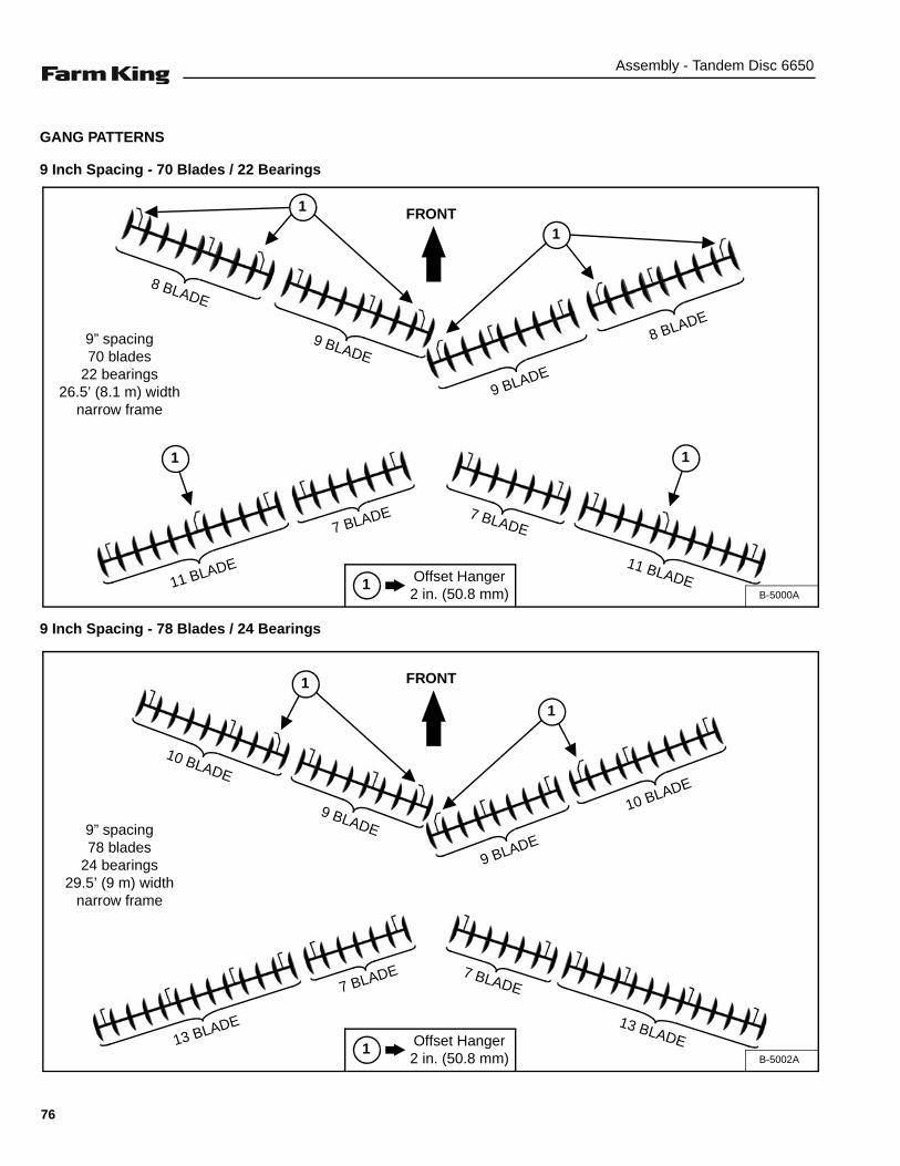
Assembly - Tandem Disc 6650
GANG PATTERNS
9 Inch Spacing - 70 Blades / 22 Bearings
9 Inch Spacing - 78 Blades / 24 Bearings
1 Offset Hanger 2 in. (50.8 mm) B-5000A
8 BLADE
FRONT1
9” spacing70 blades
22 bearings26.5’ (8.1 m) width
narrow frame
1
1 1
9 BLADE
9 BLADE
8 BLADE
7 BLADE7 BLADE
11 BLADE11 BLADE
1 Offset Hanger 2 in. (50.8 mm) B-5002A
10 BLADE
FRONT
1
1
9 BLADE
9 BLADE
10 BLADE
7 BLADE 7 BLADE
13 BLADE 13 BLADE
9” spacing78 blades
24 bearings29.5’ (9 m) width
narrow frame
76
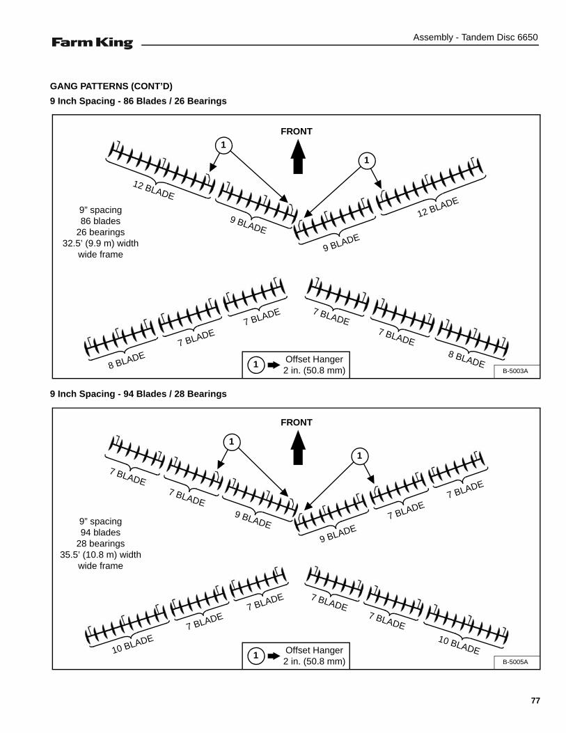
Assembly - Tandem Disc 6650
GANG PATTERNS (CONT’D)
9 Inch Spacing - 86 Blades / 26 Bearings
9 Inch Spacing - 94 Blades / 28 Bearings
1 Offset Hanger 2 in. (50.8 mm) B-5003A
12 BLADE
FRONT
1
1
9 BLADE
12 BLADE
9 BLADE
7 BLADE 7 BLADE
7 BLADE
8 BLADE 8 BLADE
7 BLADE
9” spacing86 blades
26 bearings32.5’ (9.9 m) width
wide frame
1 Offset Hanger 2 in. (50.8 mm) B-5005A
7 BLADE
FRONT
7 BLADE9 BLADE
1
1
7 BLADE
9 BLADE
7 BLADE
7 BLADE 7 BLADE
7 BLADE
10 BLADE 10 BLADE
7 BLADE
9” spacing94 blades
28 bearings35.5’ (10.8 m) width
wide frame
77
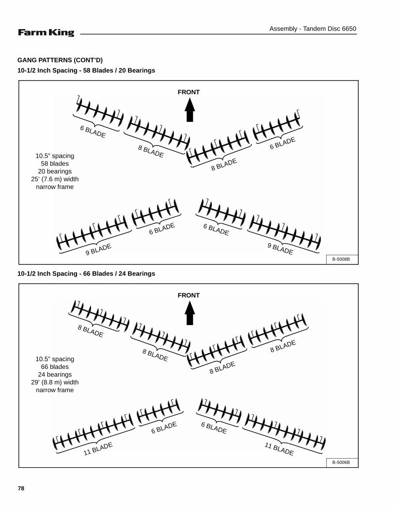
Assembly - Tandem Disc 6650
GANG PATTERNS (CONT’D)
10-1/2 Inch Spacing - 58 Blades / 20 Bearings
10-1/2 Inch Spacing - 66 Blades / 24 Bearings
B-5008B
6 BLADE
FRONT
8 BLADE6 BLADE
8 BLADE
6 BLADE 6 BLADE
9 BLADE 9 BLADE
10.5” spacing58 blades
20 bearings25’ (7.6 m) width
narrow frame
B-5006B
8 BLADE
FRONT
8 BLADE
8 BLADE
8 BLADE
6 BLADE 6 BLADE
11 BLADE 11 BLADE
10.5” spacing66 blades
24 bearings29’ (8.8 m) width
narrow frame
78
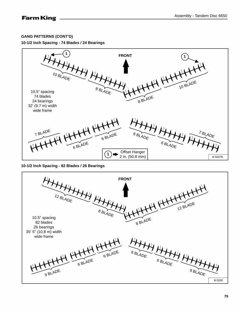
Assembly - Tandem Disc 6650
GANG PATTERNS (CONT’D)
10-1/2 Inch Spacing - 74 Blades / 24 Bearings
10-1/2 Inch Spacing - 82 Blades / 26 Bearings
B-5007B
10 BLADE
FRONT
8 BLADE
8 BLADE
10 BLADE
6 BLADE 6 BLADE7 BLADE
6 BLADE
1 Offset Hanger 2 in. (50.8 mm)
11
6 BLADE
7 BLADE
10.5” spacing74 blades
24 bearings32’ (9.7 m) width
wide frame
B-5200
12 BLADE
FRONT
8 BLADE
12 BLADE
8 BLADE
6 BLADE
6 BLADE
9 BLADE 9 BLADE
10.5” spacing82 blades
26 bearings35’ 5” (10.8 m) width
wide frame
6 BLADE
6 BLADE
79

Assembly - Tandem Disc 6650
80

Operation - Tandem Disc 6650
OPERATION
GENERAL INFORMATION . . . . . . . . . . . . . . . . . . . . . . . . . . . . . . . . . . . . . . . . . . . . . . . . . . . . . . . 83Pre - Operation Checklist . . . . . . . . . . . . . . . . . . . . . . . . . . . . . . . . . . . . . . . . . . . . . . . . . . . . . . 83Break - In Checklist . . . . . . . . . . . . . . . . . . . . . . . . . . . . . . . . . . . . . . . . . . . . . . . . . . . . . . . . . . . 84Tractor Requirements . . . . . . . . . . . . . . . . . . . . . . . . . . . . . . . . . . . . . . . . . . . . . . . . . . . . . . . . . 85Entering And Leaving The Operator’s Position . . . . . . . . . . . . . . . . . . . . . . . . . . . . . . . . . . . . . . 85
INITIAL SET-UP . . . . . . . . . . . . . . . . . . . . . . . . . . . . . . . . . . . . . . . . . . . . . . . . . . . . . . . . . . . . . . . . 86Connecting The Tandem Disc To The Tractor . . . . . . . . . . . . . . . . . . . . . . . . . . . . . . . . . . . . . . .86Connecting Hydraulic Lines . . . . . . . . . . . . . . . . . . . . . . . . . . . . . . . . . . . . . . . . . . . . . . . . . . . . 88Connect Electrical Harness . . . . . . . . . . . . . . . . . . . . . . . . . . . . . . . . . . . . . . . . . . . . . . . . . . . . 88Lateral Adjustment . . . . . . . . . . . . . . . . . . . . . . . . . . . . . . . . . . . . . . . . . . . . . . . . . . . . . . . . . . . 89Front To Rear Adjustment . . . . . . . . . . . . . . . . . . . . . . . . . . . . . . . . . . . . . . . . . . . . . . . . . . . . . . 91Setting Discing Depth . . . . . . . . . . . . . . . . . . . . . . . . . . . . . . . . . . . . . . . . . . . . . . . . . . . . . . . . . 91Leveling Wing Frames . . . . . . . . . . . . . . . . . . . . . . . . . . . . . . . . . . . . . . . . . . . . . . . . . . . . . . . . . 92
OPERATING THE TANDEM DISC . . . . . . . . . . . . . . . . . . . . . . . . . . . . . . . . . . . . . . . . . . . . . . . . . . 93Field Operation . . . . . . . . . . . . . . . . . . . . . . . . . . . . . . . . . . . . . . . . . . . . . . . . . . . . . . . . . . . . . . 93Rephasing Rockshaft Cylinders . . . . . . . . . . . . . . . . . . . . . . . . . . . . . . . . . . . . . . . . . . . . . . . . .95
ADDITIONAL OPERATING RECOMMENDATIONS . . . . . . . . . . . . . . . . . . . . . . . . . . . . . . . . . . . . 95Remove Ridge At Center Of Disc . . . . . . . . . . . . . . . . . . . . . . . . . . . . . . . . . . . . . . . . . . . . . . . . 95Remove Furrow At Center Of Disc . . . . . . . . . . . . . . . . . . . . . . . . . . . . . . . . . . . . . . . . . . . . . . . 95Remove Unbroken Ground Left By Front Gangs . . . . . . . . . . . . . . . . . . . . . . . . . . . . . . . . . . . . 95Reduce Gang Plugging . . . . . . . . . . . . . . . . . . . . . . . . . . . . . . . . . . . . . . . . . . . . . . . . . . . . . . . . 95
TRANSPORTING . . . . . . . . . . . . . . . . . . . . . . . . . . . . . . . . . . . . . . . . . . . . . . . . . . . . . . . . . . . . . . . 96Requirements . . . . . . . . . . . . . . . . . . . . . . . . . . . . . . . . . . . . . . . . . . . . . . . . . . . . . . . . . . . . . . .96Transport Position . . . . . . . . . . . . . . . . . . . . . . . . . . . . . . . . . . . . . . . . . . . . . . . . . . . . . . . . . . . .96
81

Operation - Tandem Disc 6650
82

Operation - Tandem Disc 6650
GENERAL INFORMATION
Pre - Operation Checklist
Before operating the Tandem Disc for the first time andeach time thereafter, check the following items:
1. Lubricate the equipment per the schedule outlined inthe Maintenance Section. (See “SERVICESCHEDULE” on page 101.)
2. Check the Tandem Disc hitch for damaged, loose ormissing parts. Repair as needed before operation.
3. Check that center frame tire pressure is 90 psi (621kpa).
4. Check that wing frame tire pressure is 60 psi (414kpa).
5. Check that wheel bolt torque is 130 ft-Ib (176.3 N•m).
6. Fully clean the equipment. (See “CLEANING THETANDEM DISC” on page 109.)
7. Check tandem disc for damaged or loosecomponents and hardware. Replace damagedcomponents (if required) and tighten all hardwarebefore operating the tandem disc.
8. Check wings for proper operation. Adjust wings asneeded before operating the tandem disc.
9. Inspect all electrical connections to ensure properfunction of the machine.
10. Inspect all safety reflective decals, slow movingvehicle decals and lights where applicable.
11. Check condition of all hydraulic components for leaks.Repair as required.
NOTE: Do not operate with hydraulic leaks.
12. Verify that the tandem disc is properly connected tothe tractor with the safety chain.
MOVING PART HAZARD
To prevent serious injury or death from movingparts:
• Clear area of all bystanders before starting ormoving the tractor and disc.
• Keep hands, feet, hair and clothing away frommoving parts.
• Disconnect and lockout power source beforeadjusting or servicing.
• Do not stand or climb on machine whenoperating.
AVOID INJURY OR DEATH
Wear safety glasses to prevent eye injury when anyof the following conditions exist:
• When fluids are under pressure.
• Flying debris or loose material is present.
• Engine is running.
• Tools are being used.
Leaking fluids under pressure can enter the skinand cause serious injury or death. Immediatemedical attention is required. Wear goggles. Usecardboard to check for leaks.
83

Operation - Tandem Disc 6650
Break - In Checklist
Check the following mechanical items after 1 hour ofoperation and again after 10 hours of operation:
1. Check condition of all hydraulic components for leaks.Tighten fittings to correct leaks or replacecomponents. Do not operate with hydraulic leaks.
Figure 118
2. Check the tandem disc hitch for damaged, loose ormissing parts [Figure 118]. Repair as needed beforeoperation.
3. Check for loose fasteners and hardware. Tighten asrequired.
4. Check that center frame tire pressure is 90 psi (621kpa).
5. Check that wing frame tire pressure is 60 psi (414kpa).
6. Check that wheel bolt torque is 130 ft-Ib (176.3 N•m).
B-5192
Wheel bolts must be kept tight. If bolts are not tight,bolts will loosen causing severe damage to hub,wheel and tire. Check wheel bolts periodically,especially the first few hours of either transport orfield work.
84
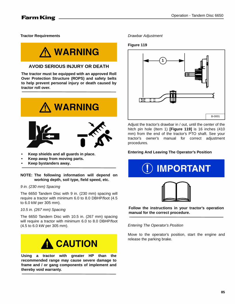
Operation - Tandem Disc 6650
Tractor Requirements
NOTE: The following information will depend onworking depth, soil type, field speed, etc.
9 in. (230 mm) Spacing
The 6650 Tandem Disc with 9 in. (230 mm) spacing willrequire a tractor with minimum 6.0 to 8.0 DBHP/foot (4.5to 6.0 kW per 305 mm).
10.5 in. (267 mm) Spacing
The 6650 Tandem Disc with 10.5 in. (267 mm) spacingwill require a tractor with minimum 6.0 to 8.0 DBHP/foot(4.5 to 6.0 kW per 305 mm).
Drawbar Adjustment
Figure 119
Adjust the tractor’s drawbar in / out, until the center of thehitch pin hole (Item 1) [Figure 119] is 16 inches (410mm) from the end of the tractor’s PTO shaft. See yourtractor’s owner’s manual for correct adjustmentprocedures.
Entering And Leaving The Operator’s Position
Entering The Operator’s Position
Move to the operator’s position, start the engine andrelease the parking brake.
AVOID SERIOUS INJURY OR DEATH
The tractor must be equipped with an approved RollOver Protection Structure (ROPS) and safety beltsto help prevent personal injury or death caused bytractor roll over.
• Keep shields and all guards in place.• Keep away from moving parts.• Keep bystanders away.
Using a tractor with greater HP than therecommended range may cause severe damage toframe and / or gang components of implement andthereby void warranty.
B-0001
1
Follow the instructions in your tractor’s operationmanual for the correct procedure.
85

Operation - Tandem Disc 6650
Leaving The Operator’s Position
Park the tractor / equipment on a flat level surface.
Place all controls in neutral, engage the park brake, stopthe engine and wait for all moving parts to stop. Leavethe operator’s position.
INITIAL SET-UP
Connecting The Tandem Disc To The Tractor
Always inspect the tractor’s drawbar and tandem dischitch before connecting. See the tractor’s owner’smanual.
Verify that the tractor’s drawbar is adjusted correctly foruse with the Tandem Disc. (See “Drawbar Adjustment” onpage 85.)
Enter the operator’s position. (See “Entering TheOperator’s Position” on page 85.)
Move the tractor into position in front of the Tandem Disc.
Move the tractor backwards, aligning the drawbar with thetandem disc hitch.
NOTE: The jack may need to be lowered or raised forproper alignment of the drawbar and hitch.
If the tandem disc hitch needs to be adjusted, stop thetractor when drawbar is just in front of the Tandem Dischitch.
Leave the operator’s position. (See “Leaving TheOperator’s Position” on page 86.)
AVOID INJURY OR DEATHBefore you leave the operator’s position:• Always park on a flat level surface.• Place all controls in NEUTRAL.• Engage the park brake.• Stop the engine and remove the key.• Wait for all moving parts to stop.
AVOID INJURY OR DEATHBefore moving the tractor, look in all directions andmake sure no bystanders, especially small childrenare in the work area. Do not allow anyone betweenthe tractor and the equipment when backing up tothe equipment for connecting.
86
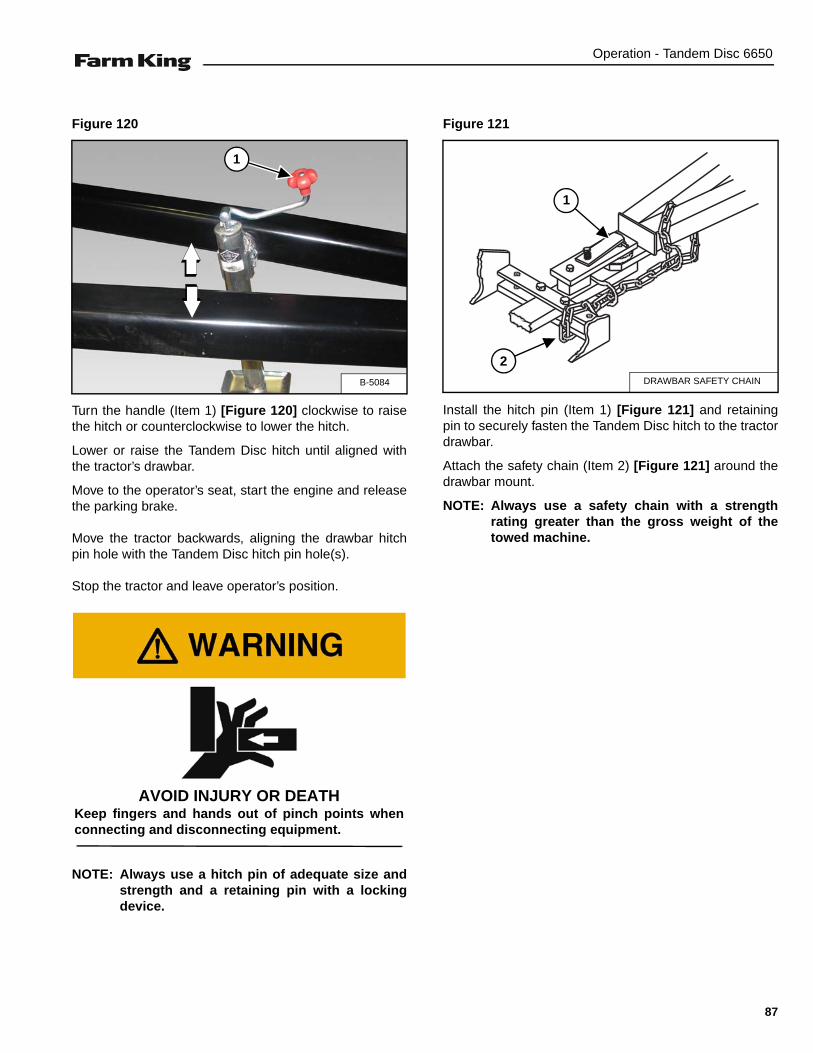
Operation - Tandem Disc 6650
Figure 120
Turn the handle (Item 1) [Figure 120] clockwise to raisethe hitch or counterclockwise to lower the hitch.
Lower or raise the Tandem Disc hitch until aligned withthe tractor’s drawbar.
Move to the operator’s seat, start the engine and releasethe parking brake.
Move the tractor backwards, aligning the drawbar hitchpin hole with the Tandem Disc hitch pin hole(s).
Stop the tractor and leave operator’s position.
NOTE: Always use a hitch pin of adequate size andstrength and a retaining pin with a lockingdevice.
Figure 121
Install the hitch pin (Item 1) [Figure 121] and retainingpin to securely fasten the Tandem Disc hitch to the tractordrawbar.
Attach the safety chain (Item 2) [Figure 121] around thedrawbar mount.
NOTE: Always use a safety chain with a strengthrating greater than the gross weight of thetowed machine.
B-5084
1
AVOID INJURY OR DEATHKeep fingers and hands out of pinch points whenconnecting and disconnecting equipment.
DRAWBAR SAFETY CHAIN
1
2
87

Operation - Tandem Disc 6650
Connecting Hydraulic Lines
NOTE: Make sure the quick couplers are fullyengaged. If the quick couplers do not fullyengage, check to see that the couplers are thesame size and type.
To Connect:
Figure 122
Connect the hydraulic lines to the tractor [Figure 122].
1. Raise / Lower (Green Ties).
2. Fold / Unfold (Blue Ties).
To Disconnect:
Pull on the hydraulic lines to disconnect.
Connect Electrical Harness
Connect the tandem disc’s lighting harness to thetractor’s electrical system.
HIGH PRESSURE FLUID HAZARD
To prevent serious injury or death from highpressure fluid:
• Relieve pressure on system before repairing oradjusting.
• Wear proper hand and eye protection whensearching for leaks. Use wood or cardboardinstead of hands.
• Keep all components in good repair.
• Contain and dispose of any oil leakage in anenvironmentally safe manner.
• Thoroughly clean the quick couplers beforemaking connections. Dirt can quickly damagethe system.
B-0531
1
2
AVOID BURNS
Hydraulic fluid, tubes, fittings and quick couplerscan get hot when running equipment. Be carefulwhen connecting and disconnecting quick couplers.
88

Operation - Tandem Disc 6650
Lateral Adjustment
Move to the operator’s position, start the engine andrelease the parking brake. (See “Entering The Operator’sPosition” on page 85.)
Park the tractor / equipment on a flat level surface.
Stop the tractor, place all controls in neutral, engage thepark brake, stop the engine and wait for all moving partsto stop. Leave the operator’s position. (See “Leaving TheOperator’s Position” on page 86.)
Front Gangs
Figure 123
Loosen bearing hanger U-bolts and position the frontinside gang sections, so that the leading edge of insideblade is approximately 2-1/2” (63.5 mm) past center ofmain frame [Figure 123].
The tandem disc frame must be leveled front to rear& side to side until the tandem disc is parallel withthe ground prior to operation.
AVOID INJURY OR DEATH
Wear safety glasses to prevent eye injury when anyof the following conditions exist:
• When fluids are under pressure.
• Flying debris or loose material is present.
• Engine is running.
• Tools are being used. FRONT GANGS
CENTER OF MAIN FRAME
2-1/2 in. (63.5 mm)
2-1/2 in. (63.5 mm)
Always tighten inside hanger bearing u-bolts first,while maintaining the 2-1/2” (63.5 mm) spacing pastcenter of main frame. Tighten all bearing hanger u-bolts to 430 ft.-lb. (583 N•m) torque.
Hanger bracket must be sitting square with gangbeam before tightening u-bolts.
89

Operation - Tandem Disc 6650
Rear Gangs
NOTE: The distance the rear gangs are set apart isdetermined by the discing speed, discingdepth, gang angle and soil conditions. If therear gangs are set too close together, the reargangs will leave a ridge at center. If rear gangsare set too far apart, the furrow at center leftby the front gangs will not be filled.
Figure 124
Center rear inside gang sections, so that the distancebetween the rear edge of the two inside blades (Item 1)[Figure 124], is equal to 2” (50.8 mm) less than diameterof blades with a maximum of 24” (610 mm).
EXAMPLE - if the disc is equipped with 24” (610 mm)diameter blades, the distance between the rear edge ofthe two inside blades (Item 1) [Figure 124] would be setat 22” (559 mm).
NOTE: If the disc is equipped with 26” (660 mm) or28” (711 mm) diameter blades, the distancebetween the rear edge of the two insideblades (Item 1) [Figure 124] would be set at amaximum of 24” (610 mm).
To adjust the distance between the rear gangs, loosenthe bearing hanger u-bolts and reposition the gangsections.
NOTE: It may be necessary to increase distancebetween rear gangs in order to collect enoughsoil to fill furrow.
An increase in discing speed may require rear gangs tobe set further apart. A decrease in discing speed mayrequire rear gangs to be set closer together.
Front And Rear Gang Adjustments Completed
NOTE: Before tightening bearing hanger U-bolts,ensure that each bearing hanger is positionedflat under the gang beam to avoid preloadingbearings and / or other gang components.
Tighten bearing hanger u-bolts.
The opening between the rear gang must be set at adistance that will allow furrow left by the front gangsto be filled evenly.
RIGHT FRONT GANG
CENTER OF MAIN FRAME
1
Be sure the blade to blade distance betweenindividual gangs are adjusted to match discs bladespacing.
Always tighten inside hanger bearing u-bolts first,while maintaining the desired spacing between therear edge of the two inside blades. Tighten allbearing hanger u-bolts to 430 ft.-lb. (583 N•m)torque.
90
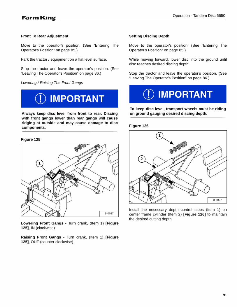
Operation - Tandem Disc 6650
Front To Rear Adjustment
Move to the operator’s position. (See “Entering TheOperator’s Position” on page 85.)
Park the tractor / equipment on a flat level surface.
Stop the tractor and leave the operator’s position. (See“Leaving The Operator’s Position” on page 86.)
Lowering / Raising The Front Gangs
Figure 125
Lowering Front Gangs - Turn crank, (Item 1) [Figure125], IN (clockwise)
Raising Front Gangs - Turn crank, (Item 1) [Figure125], OUT (counter clockwise)
Setting Discing Depth
Move to the operator’s position. (See “Entering TheOperator’s Position” on page 85.)
While moving forward, lower disc into the ground untildisc reaches desired discing depth.
Stop the tractor and leave the operator’s position. (See“Leaving The Operator’s Position” on page 86.)
Figure 126
Install the necessary depth control stops (Item 1) oncenter frame cylinder (Item 2) [Figure 126] to maintainthe desired cutting depth.
Always keep disc level from front to rear. Discingwith front gangs lower than rear gangs will causeridging at outside and may cause damage to disccomponents.
B-5027
1
To keep disc level, transport wheels must be ridingon ground gauging desired discing depth.
B-5027
1
2
91

Operation - Tandem Disc 6650
Leveling Wing Frames
Move to the operator’s position. (See “Entering TheOperator’s Position” on page 85.)
Move the tractor / equipment to a flat level surface.
Stop the tractor and leave the operator’s position. (See“Leaving The Operator’s Position” on page 86.)
Raising Outside Wing Frame
Figure 127
Loosen rear nut (Item 1) [Figure 127] of I-bolt andtighten front nut. This will lower the wheels raisingoutside of wing.
After adjustments are complete, lock I-bolt by tighteningrear nut against I-bolt holder.
Lowering Outside Wing Frame
Figure 128
Loosen front nut (Item 1) [Figure 128] of I-bolt andtighten rear nut. This will raise the wheels allowingoutside of wing to lower.
After adjustments are complete, lock I-bolt by tighteningrear nut against I-bolt holder.
Before leveling wing frames, verify center frame islevel from front to rear.
For even blade penetration, outside of wing framesmust be level with center frame or even 1/2 in. (12.7mm) higher than center frame.
B-5021
1
B-5021
1
Verify that the axis of clevis pin is horizontal andcylinder ports are facing up. If cylinder and I-bolt arenot positioned properly, cylinder will not be free topivot when activated, causing serious damage.
If cylinder and I-bolt are not positioned properly,cylinder will not be free to pivot when activated,causing serious damage.
92
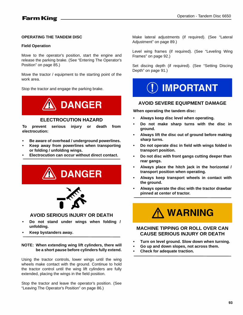
Operation - Tandem Disc 6650
OPERATING THE TANDEM DISC
Field Operation
Move to the operator’s position, start the engine andrelease the parking brake. (See “Entering The Operator’sPosition” on page 85.)
Move the tractor / equipment to the starting point of thework area.
Stop the tractor and engage the parking brake.
NOTE: When extending wing lift cylinders, there willbe a short pause before cylinders fully extend.
Using the tractor controls, lower wings until the wingwheels make contact with the ground. Continue to holdthe tractor control until the wing lift cylinders are fullyextended, placing the wings in the field position.
Stop the tractor and leave the operator’s position. (See“Leaving The Operator’s Position” on page 86.)
Make lateral adjustments (if required). (See “LateralAdjustment” on page 89.)
Level wing frames (if required). (See “Leveling WingFrames” on page 92.)
Set discing depth (if required). (See “Setting DiscingDepth” on page 91.)
ELECTROCUTION HAZARDTo prevent serious injury or death fromelectrocution:
• Be aware of overhead / underground powerlines.• Keep away from powerlines when transporting
or folding / unfolding wings.• Electrocution can occur without direct contact.
AVOID SERIOUS INJURY OR DEATH• Do not stand under wings when folding /
unfolding.
• Keep bystanders away.
AVOID SEVERE EQUIPMENT DAMAGE
When operating the tandem disc:
• Always keep disc level when operating.
• Do not make sharp turns with the disc inground.
• Always lift the disc out of ground before makingsharp turns.
• Do not operate disc in field with wings folded intransport position.
• Do not disc with front gangs cutting deeper thanrear gangs.
• Always place the hitch jack in the horizontal /transport position when operating.
• Always keep transport wheels in contact withthe ground.
• Always operate the disc with the tractor drawbarpinned at center of tractor.
MACHINE TIPPING OR ROLL OVER CAN CAUSE SERIOUS INJURY OR DEATH
• Turn on level ground. Slow down when turning.• Go up and down slopes, not across them.• Check for adequate traction.
93

Operation - Tandem Disc 6650
Move to the operator’s position, start the engine and release the parking brake. (See “Entering The Operator’sPosition” on page 85.)
Recommended operating speed is 5 - 7 mph (8 - 11 kph).
Move tractor and tandem disc forward, slowly lower tandem disc into the ground until the transport wheels makecontact with the ground and the disc reaches desired discing depth.
Figure 129
To keep the tandem disc level, transport wheels must be contacting the ground gauging desired discing depth(CORRECT) [Figure 129].
NOTE: If conditions are such that disc cannot penetrate to maximum depth, Do Not raise transport wheels offground (INCORRECT) [Figure 129]. Raised transport wheels may cause front of disc to drop causing frontgangs to cut deeper than rear gangs.
B-5011
CORRECT
4 in.(101.6 mm)
4 in.(101.6 mm)
INCORRECT
TRANSPORT WHEELS
GROUND
GROUND
TRANSPORT WHEELS
94
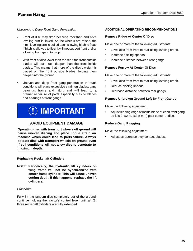
Operation - Tandem Disc 6650
Uneven And Deep Front Gang Penetration
• Front of disc may drop because rockshaft and hitchleveling arm is linked. As the wheels are raised, thehitch leveling arm is pulled back allowing hitch to float.If hitch is allowed to float it will not support front of discallowing front gang to drop.
• With front of disc lower than the rear, the front outsideblades will cut much deeper than the front insideblades. This means that more of the disc’s weight isplaced on the front outside blades, forcing themdeeper into the ground.
• Uneven and deep front gang penetration in toughconditions will place excessive strain on blades, gangbearings, frame and hitch, and will lead to apremature failure of parts especially outside bladesand bearings of front gangs.
Rephasing Rockshaft Cylinders
NOTE: Periodically, the hydraulic lift cylinders onwing frame will not be synchronized withcenter frame cylinder. This will cause unevencutting depth. If this happens, rephase the liftcylinders.
Procedure
Fully lift the tandem disc completely out of the ground,continue holding the tractor’s control lever until all (3)three rockshaft cylinders are fully extended.
ADDITIONAL OPERATING RECOMMENDATIONS
Remove Ridge At Center Of Disc
Make one or more of the following adjustments:
• Level disc from front to rear using leveling crank.
• Increase discing speeds.
• Increase distance between rear gangs.
Remove Furrow At Center Of Disc
Make one or more of the following adjustments:
• Level disc from front to rear using leveling crank.
• Reduce discing speeds.
• Decrease distance between rear gangs.
Remove Unbroken Ground Left By Front Gangs
Make the following adjustment:
• Adjust leading edge of inside blade of each front gangso it is 2-1/2 in. (63.5 mm) past center of disc.
Reduce Gang Plugging
Make the following adjustment:
• Adjust scrapers so they contact blades.
AVOID EQUIPMENT DAMAGE
Operating disc with transport wheels off ground willcause uneven discing and place undue strain onmachine which could lead to parts failure. Alwaysoperate disc with transport wheels on ground evenif soil conditions will not allow disc to penetrate tomaximum depth.
95

Operation - Tandem Disc 6650
TRANSPORTING
Requirements
Comply with federal, state, local and provincial lawsregarding the transport of farm equipment on publicroadways.
Verify that the tractor is approved for transporting theequipment and that the equipment is securely attached tothe tractor.
Verify safety chain is installed and properly connectedbefore transporting equipment.
Verify that the SMV (Slow Moving Vehicle) emblem, alllights and reflectors are clean and visible.
Figure 130
When transporting disc, always place the complete depthcontrol package 17 in. (431.80 mm) long on shaft of 4 in.x 24 in. (102 mm x 610 mm) main frame lift cylinder (Item1) [Figure 130].
Transport Position
Wings fully raised, depth control package in place andlockup valves in closed position.
AVOID SERIOUS INJURY OR DEATH
Use of an unapproved hitch or tractor can result inloss of control, leading to serious injury or death.
Tractor and hitch must have the rated capacity totow equipment.
AVOID SERIOUS INJURY OR DEATH
Excess weight will greatly increase tractor stoppingdistance and may cause the operator to lose controlof the tractor.
Tractor must have adequate braking capacity tosafely control tandem disc GVW (Gross VehicleWeight) trailing load. Do not tow over 20 mph (32kph). Tractor unit should weigh approximately 67%of GVW.
B-5191A
1
All depth stops must be installed and lock up valvesclosed when transporting disc.
96

Maintenance - Tandem Disc 6650
MAINTENANCE
TROUBLESHOOTING . . . . . . . . . . . . . . . . . . . . . . . . . . . . . . . . . . . . . . . . . . . . . . . . . . . . . . . . . . . 99General Chart . . . . . . . . . . . . . . . . . . . . . . . . . . . . . . . . . . . . . . . . . . . . . . . . . . . . . . . . . . . . . . . 99
SERVICE SCHEDULE . . . . . . . . . . . . . . . . . . . . . . . . . . . . . . . . . . . . . . . . . . . . . . . . . . . . . . . . . . 101Maintenance Intervals . . . . . . . . . . . . . . . . . . . . . . . . . . . . . . . . . . . . . . . . . . . . . . . . . . . . . . . . 101
LUBRICATION . . . . . . . . . . . . . . . . . . . . . . . . . . . . . . . . . . . . . . . . . . . . . . . . . . . . . . . . . . . . . . . . 102Recommendations . . . . . . . . . . . . . . . . . . . . . . . . . . . . . . . . . . . . . . . . . . . . . . . . . . . . . . . . . . 102Locations . . . . . . . . . . . . . . . . . . . . . . . . . . . . . . . . . . . . . . . . . . . . . . . . . . . . . . . . . . . . . . . . . . 102
BEARING HANGERS . . . . . . . . . . . . . . . . . . . . . . . . . . . . . . . . . . . . . . . . . . . . . . . . . . . . . . . . . . 105Inspection . . . . . . . . . . . . . . . . . . . . . . . . . . . . . . . . . . . . . . . . . . . . . . . . . . . . . . . . . . . . . . . . . 105
LEVELING CRANK . . . . . . . . . . . . . . . . . . . . . . . . . . . . . . . . . . . . . . . . . . . . . . . . . . . . . . . . . . . . 105Inspection . . . . . . . . . . . . . . . . . . . . . . . . . . . . . . . . . . . . . . . . . . . . . . . . . . . . . . . . . . . . . . . . . 105
GANG SECTION . . . . . . . . . . . . . . . . . . . . . . . . . . . . . . . . . . . . . . . . . . . . . . . . . . . . . . . . . . . . . .106Gang Bolt Inspection . . . . . . . . . . . . . . . . . . . . . . . . . . . . . . . . . . . . . . . . . . . . . . . . . . . . . . . . . 106Tightening Gang Bolt . . . . . . . . . . . . . . . . . . . . . . . . . . . . . . . . . . . . . . . . . . . . . . . . . . . . . . . . 106
AXLES . . . . . . . . . . . . . . . . . . . . . . . . . . . . . . . . . . . . . . . . . . . . . . . . . . . . . . . . . . . . . . . . . . . . . . 107Wheel Bolts Torque . . . . . . . . . . . . . . . . . . . . . . . . . . . . . . . . . . . . . . . . . . . . . . . . . . . . . . . . . . 107Tire / Wheel Replacement . . . . . . . . . . . . . . . . . . . . . . . . . . . . . . . . . . . . . . . . . . . . . . . . . . . . 107Wheel Bearings . . . . . . . . . . . . . . . . . . . . . . . . . . . . . . . . . . . . . . . . . . . . . . . . . . . . . . . . . . . . 108Tire Pressure . . . . . . . . . . . . . . . . . . . . . . . . . . . . . . . . . . . . . . . . . . . . . . . . . . . . . . . . . . . . . .108
CLEANING THE TANDEM DISC . . . . . . . . . . . . . . . . . . . . . . . . . . . . . . . . . . . . . . . . . . . . . . . . . . 109
SERVICING T2-215 BEARINGS (IMPORTANT NOTES) . . . . . . . . . . . . . . . . . . . . . . . . . . . . . . . 109
WING LIFT CYLINDER . . . . . . . . . . . . . . . . . . . . . . . . . . . . . . . . . . . . . . . . . . . . . . . . . . . . . . . . . 109Removal And Installation . . . . . . . . . . . . . . . . . . . . . . . . . . . . . . . . . . . . . . . . . . . . . . . . . . . . . 109
WALKING BEAMS . . . . . . . . . . . . . . . . . . . . . . . . . . . . . . . . . . . . . . . . . . . . . . . . . . . . . . . . . . . . . 110Installing The Walking Beams . . . . . . . . . . . . . . . . . . . . . . . . . . . . . . . . . . . . . . . . . . . . . . . . . . 110
HITCH COMPRESSION SPRING . . . . . . . . . . . . . . . . . . . . . . . . . . . . . . . . . . . . . . . . . . . . . . . . . 114
FRAME SPRING BUSHINGS . . . . . . . . . . . . . . . . . . . . . . . . . . . . . . . . . . . . . . . . . . . . . . . . . . . . 115Removal And Installation . . . . . . . . . . . . . . . . . . . . . . . . . . . . . . . . . . . . . . . . . . . . . . . . . . . . . 115
ROCKSHAFT SPRING BUSHINGS . . . . . . . . . . . . . . . . . . . . . . . . . . . . . . . . . . . . . . . . . . . . . . . . 115Removal And Installation . . . . . . . . . . . . . . . . . . . . . . . . . . . . . . . . . . . . . . . . . . . . . . . . . . . . . 115
97
Maintenance - Tandem Disc 6650
SCRAPER BARS . . . . . . . . . . . . . . . . . . . . . . . . . . . . . . . . . . . . . . . . . . . . . . . . . . . . . . . . . . . . . .116Removal And Installation . . . . . . . . . . . . . . . . . . . . . . . . . . . . . . . . . . . . . . . . . . . . . . . . . . . . .116
SAFETY SIGN (DECAL) INSTALLATION . . . . . . . . . . . . . . . . . . . . . . . . . . . . . . . . . . . . . . . . . . . .116Procedure . . . . . . . . . . . . . . . . . . . . . . . . . . . . . . . . . . . . . . . . . . . . . . . . . . . . . . . . . . . . . . . . .116
STORAGE AND RETURN TO SERVICE . . . . . . . . . . . . . . . . . . . . . . . . . . . . . . . . . . . . . . . . . . . .117Storage . . . . . . . . . . . . . . . . . . . . . . . . . . . . . . . . . . . . . . . . . . . . . . . . . . . . . . . . . . . . . . . . . . .117Return To Service . . . . . . . . . . . . . . . . . . . . . . . . . . . . . . . . . . . . . . . . . . . . . . . . . . . . . . . . . . .117
98

Maintenance - Tandem Disc 6650
TROUBLESHOOTING
General Chart
NOTE: If a problem is encountered that is difficult to solve, even after having read through this troubleshootingsection, please call your local distributor or dealer. Before you call, please have this Operator And PartsManual and the serial number of your machine at hand.
PROBLEM CAUSE CORRECTION
Outside blades of front wings arecutting too deep causing disc to ridgeat outside.
Wheels raised off ground causing frontdisc to drop.
Lower wheels to ground to gaugediscing depth.
Tire pressure is low on outer wheelscausing disc to cut deep at outside.
Inflate tire, (See “Tire Pressure” onpage 108.)
Disc is lower at front than at rear. Using leveling crank, raise front of disc.
Wing wheel not adjusted for propercutting depth.
Raise outside of wing by adjusting liftcylinder I-bolt.
Wing rockshaft cylinders are notsynchronized with center framerockshaft cylinder.
Rephase rockshaft cylinders.
Outside blades of front wings are notcutting deep enough.
Disc is higher at front than rear. Using leveling crank, raise front of disc.
Outside blades on front and reargangs are cutting too deep.
Tire pressure is low for wing wheelscausing wings to cut deeper.
Check tire inflation for all wheels. (See“Tire Pressure” on page 108.)
Outside of wing frame is lower thanmain frame.
Raise outside of wing with wingrockshaft cylinder anchor bolt.
Wing rockshaft cylinders are notsynchronized with center framerockshaft cylinder.
Rephase rockshaft cylinders.
Outside blades on front and reargangs are not cutting deep enough.
Tire pressure is lower on center sectionwheels than wing section wheelcausing center section to cut deeper
Check tire inflation for all wheels. (See“Tire Pressure” on page 108.)
Outside of wing frame(s) is higher thanmain frame.
Lower outside of wing with wingrockshaft cylinder anchor bolt.
Wing rockshaft cylinder is notsynchronized with main framerockshaft cylinder.
Rephase rockshaft cylinders.
Instructions are necessary before operating or servicing equipment. Read and understand theOperator And Parts Manual and safety signs (decals) on equipment. Follow warnings andinstructions in the manuals when making repairs, adjustments or servicing. Check for correctfunction after adjustments, repairs or service. Untrained operators and failure to follow instructionscan cause injury or death.
99

Maintenance - Tandem Disc 6650
Disc is leaving a ridge at center ofdiscing
Rear gangs are cutting deeperthan front gangs.
Level disc.
High discing speed is causing disc tothrow dirt further resulting in a pile atcenter.
Decrease discing speed.
Rear gangs are too close together. Increase distance between rear gangs.
Rear gangs are not filling furrow leftby front gangs at center of disc.
Front gangs are cutting deeper thanrear gangs.
Level disc.
A low discing speed is causing disc tonot throw dirt far enough to fill furrowleft by front center blades.
Increase discing speed.
Rear gangs are too far apart. Decrease distance betweenrear gangs.
Front gangs are leaving unbrokenground at center of disc.
Front gangs are either overlapped toomuch or not enough.
Adjust overlap of front gangs.
Disc gangs are plugging. Scrapers are too far from blades. Adjust scrapers so they are contactingblades.
Thrash conditions too heavy for yourmachine cylinder(s).
Contact your dealer.
When raising disc out of ground, mainframe comes out of ground whileoutside of wing(s) lags behind or doesnot come out of ground.
Piston seals on wing rockshaftcylinder(s) are damaged.
Replace piston seals of wing rockshaftcylinder.
When raising disc out of ground, mainframe rockshaft cylinder is fullyextended while wing rockshaftcylinder(s) are not fully extended.
Rockshaft cylinders not synchronized. Rephrase rockshaft cylinders.
When raising disc out of ground wing rockshaft cylinder is fully extended while main frame rockshaft cylinder(s) are not fully extended.
Rockshaft cylinders not synchronized. Rephrase rockshaft cylinders.
Outer wing blades will not penetratesoil.
Soil condition too hard for yourmachine.
Add weights to outside of wing frame.Contact your Dealer for availableweights.
All section of disc will not penetratesoil.
Soil condition too hard for yourmachine.
Contact your Dealer.
PROBLEM CAUSE CORRECTION
100
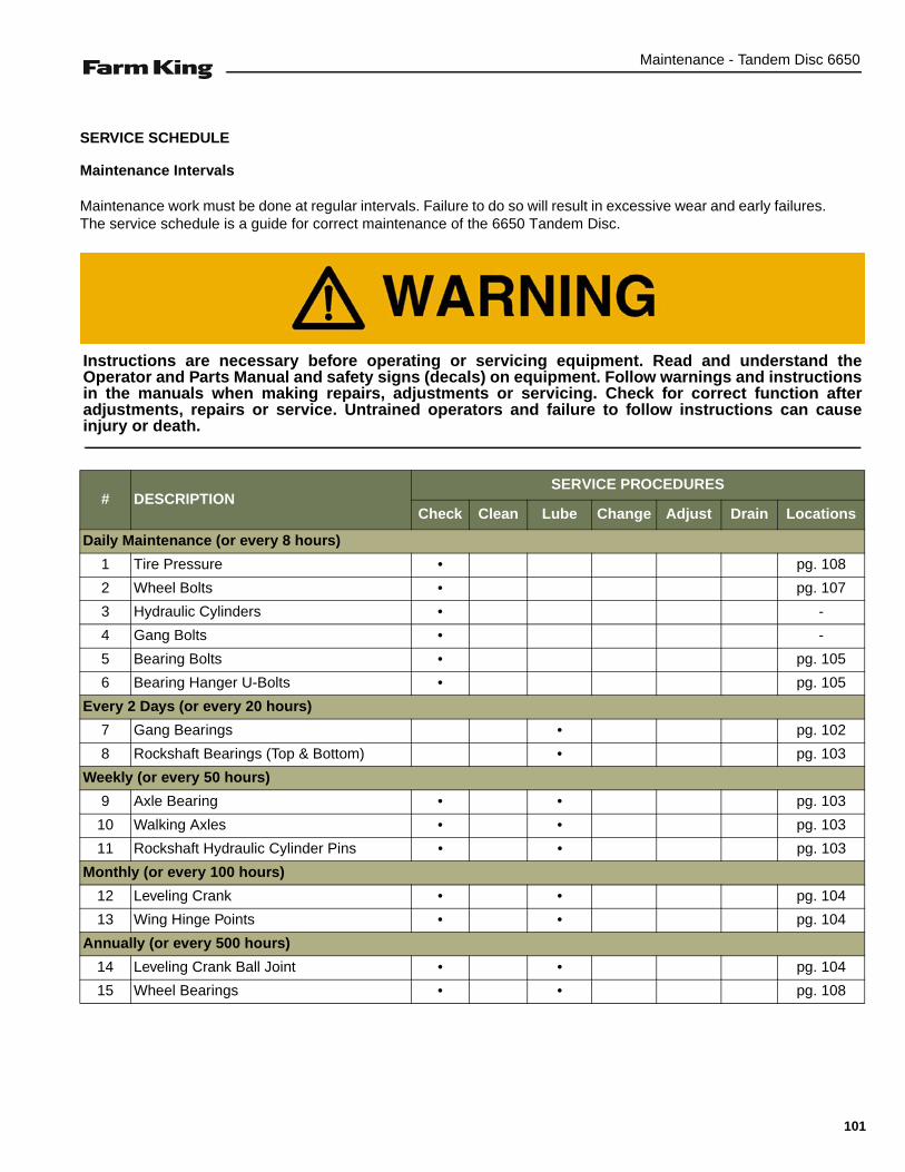
Maintenance - Tandem Disc 6650
SERVICE SCHEDULE
Maintenance Intervals
Maintenance work must be done at regular intervals. Failure to do so will result in excessive wear and early failures.The service schedule is a guide for correct maintenance of the 6650 Tandem Disc.
# DESCRIPTIONSERVICE PROCEDURES
Check Clean Lube Change Adjust Drain Locations
Daily Maintenance (or every 8 hours)
1 Tire Pressure • pg. 108
2 Wheel Bolts • pg. 107
3 Hydraulic Cylinders • -
4 Gang Bolts • -
5 Bearing Bolts • pg. 105
6 Bearing Hanger U-Bolts • pg. 105
Every 2 Days (or every 20 hours)
7 Gang Bearings • pg. 102
8 Rockshaft Bearings (Top & Bottom) • pg. 103
Weekly (or every 50 hours)
9 Axle Bearing • • pg. 103
10 Walking Axles • • pg. 103
11 Rockshaft Hydraulic Cylinder Pins • • pg. 103
Monthly (or every 100 hours)
12 Leveling Crank • • pg. 104
13 Wing Hinge Points • • pg. 104
Annually (or every 500 hours)
14 Leveling Crank Ball Joint • • pg. 104
15 Wheel Bearings • • pg. 108
Instructions are necessary before operating or servicing equipment. Read and understand theOperator and Parts Manual and safety signs (decals) on equipment. Follow warnings and instructionsin the manuals when making repairs, adjustments or servicing. Check for correct function afteradjustments, repairs or service. Untrained operators and failure to follow instructions can causeinjury or death.
101

Maintenance - Tandem Disc 6650
LUBRICATION
Recommendations
Always use a good quality multi-purpose / lithium basegrease when lubricating the equipment.
• Always use a hand-held grease gun.
• Clean fitting before greasing, to avoid injecting dirtand grit.
• Replace and repair broken fittings immediately.
• If fittings will not take grease, remove and cleanthoroughly. Replace fitting if necessary.
Locations
Lubricate the following grease locations EVERY 20HOURS:
Figure 131
Apply six - ten pumps of grease to the gang bearings(Item 1) [Figure 131] (all locations).
NOTE: 410WSS bearings shown in [Figure 131].
If 410WSS series bearings are over lubricated, thereis a possibility the seals can be pushed out. T2-215series bearings have internal seals that can not beover lubricated.
Fluid such as engine oil, hydraulic fluid, coolants,grease, etc. must be disposed of in anenvironmentally safe manner. Some regulationsrequire that certain spills and leaks on the groundmust be cleaned in a specific manner. See local,state and federal regulations for the correctdisposal.
B-5169
6-10
1
102

Maintenance - Tandem Disc 6650
Lubricate the following grease locations EVERY 20HOURS:
Figure 132
Apply six - ten pumps of grease to the rockshaft bearings(Item 1) [Figure 132] (all locations).
Lubricate the following grease locations EVERY 50HOURS:
Figure 133
Apply two - three pumps of grease to the axle bearings(Item 1) [Figure 133] (all locations).
Repacking Wheel Bearings: Remove dust cap. Greasehub until new grease comes out outer end of hub.
Lubricate the following grease locations EVERY 50HOURS:
Figure 134
Apply two - three pumps of grease to the walking axles(Item 1) [Figure 134] (all locations).
Figure 135
Apply oil to the rockshaft hydraulic cylinder pins (Item 1)[Figure 135] (all locations).
B-5049
6-10
1
Lower disc so gangs are resting on ground beforegreasing rockshaft bearings.
B-5106
2-3
1
B-5064
2-3
1
B-5131
1
103

Maintenance - Tandem Disc 6650
Lubricate the following grease locations EVERY 100HOURS:
Figure 136
Apply two - three pumps of grease to the leveling crank(Item 1) [Figure 136].
Figure 137
Apply two - three pumps of grease to the wing hingepoints (Item 1) [Figure 137] (all locations top & bottom).
Lubricate the following grease locations EVERY 500HOURS:
Figure 138
Apply oil to the leveling crank ball joint (Item 1) [Figure138].
B-5090
2-3 1
B-5096
2-3
1
B-5088A
1
104
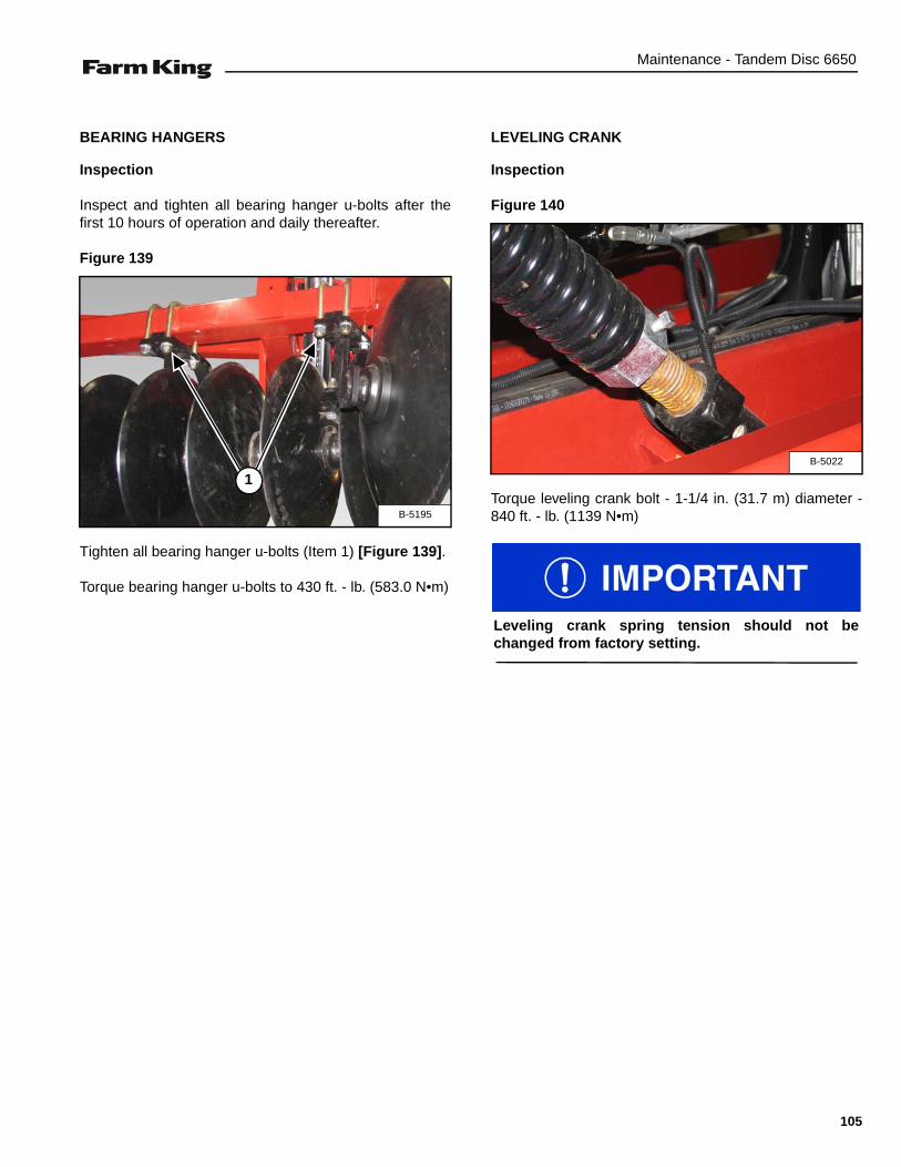
Maintenance - Tandem Disc 6650
BEARING HANGERS
Inspection
Inspect and tighten all bearing hanger u-bolts after thefirst 10 hours of operation and daily thereafter.
Figure 139
Tighten all bearing hanger u-bolts (Item 1) [Figure 139].
Torque bearing hanger u-bolts to 430 ft. - lb. (583.0 N•m)
LEVELING CRANK
Inspection
Figure 140
Torque leveling crank bolt - 1-1/4 in. (31.7 m) diameter -840 ft. - lb. (1139 N•m)B-5195
1B-5022
Leveling crank spring tension should not bechanged from factory setting.
105

Maintenance - Tandem Disc 6650
GANG SECTION
Gang Bolt Inspection
Figure 141
Visually inspect the gang bolt (Item 1) [Figure 141] daily.
Tightening Gang Bolt
Tighten 1-15/16” gang bolts to 3200 ft. - lb. (4339 N•m)torque.
NOTE: Visually inspect gang bolts daily.
Figure 142
Install a 10 ft. bar of adequate size [Figure 142] andstrength in socket wrench. Apply 320 lb. (145 kg) of forceto end of bar and tighten gang bolt to 3200 ft. - lb. (4339N•m).
NOTE: Severe damage will occur if gang bolts areloose.
Always lower the disc to the ground when servicingor making adjustments. If disc must be serviced oradjusted in the raised position, place blocks underframe. Do not rely on hydraulic lock up valves as asafety device.
B-5168
1 TORQUE BAR
10 ft. (3.05 m)
320 lb. (145 kg)
After repairing a gang, the gang bolt should be re-tightened after 2 hours of operation.
106

Maintenance - Tandem Disc 6650
AXLES
Wheel Bolts Torque
Tighten wheel bolts to 130 ft. - lb. (176.3 N•m) torque.
Tire / Wheel Replacement
Periodically check tires for cuts, bulges and damagedrims.
Park the tractor / equipment on a flat level surface.
Place all controls in neutral, engage the park brake, stopthe engine and wait for all moving parts to stop. Leavethe operator’s position.
Fully raise wings into transport position and secure withsafety chain.
Remove the eight wheel bolts and remove the tire /wheel.
Place chock blocks behind and in front of the oppositetire to be removed.
Raise axle frame with jack until the tire / wheel is slightlyoff the ground.
NOTE: Place blocks / stands under the frame tosecure the tandem disc when tire / wheel israised off the ground.
CHECK WHEEL BOLTS AFTER:1. First 5 (five) hours of field operation.
2. First 25 (twenty-five) hours of field operation.
3. First 50 (fifty) hours of field operation.
4. Every 200 (two hundred) hours of operation.
REPEAT PROCEDURE IF A WHEEL IS REMOVED OR REINSTALLED
AVOID INJURY OR DEATH
Before you leave the operator’s position:
• Always park on a flat level surface.• Place all controls in NEUTRAL.• Engage the park brake.• Stop the engine and remove the key.• Wait for all moving parts to stop.
If wings are folded into transport position, alwaysinstall a safety chain between each wing frame andmain frame to prevent wings from falling.
AVOID INJURY OR DEATH
• Always chock tires before performing anymaintenance or service.
Main frame wheels are attached with lock nuts.Remove lock nuts first, from the backside of eachhub before removing the wheel bolts.
107
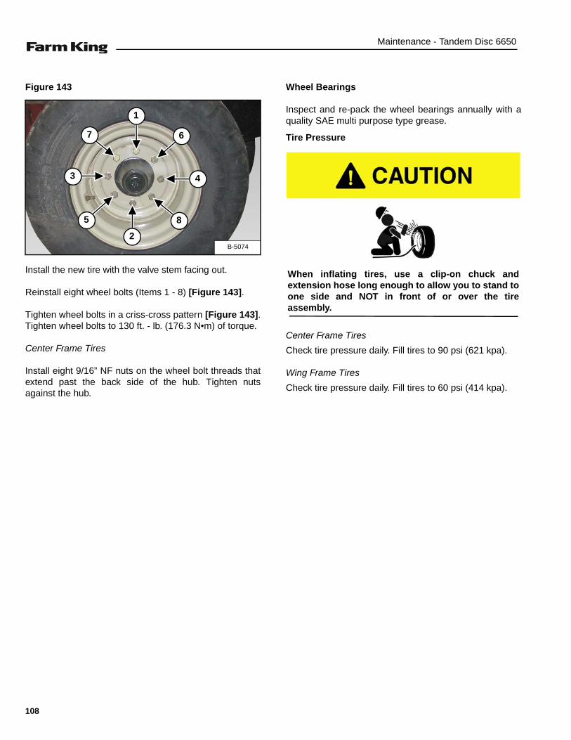
Maintenance - Tandem Disc 6650
Figure 143
Install the new tire with the valve stem facing out.
Reinstall eight wheel bolts (Items 1 - 8) [Figure 143].
Tighten wheel bolts in a criss-cross pattern [Figure 143].Tighten wheel bolts to 130 ft. - lb. (176.3 N•m) of torque.
Center Frame Tires
Install eight 9/16” NF nuts on the wheel bolt threads thatextend past the back side of the hub. Tighten nutsagainst the hub.
Wheel Bearings
Inspect and re-pack the wheel bearings annually with aquality SAE multi purpose type grease.
Tire Pressure
Center Frame Tires
Check tire pressure daily. Fill tires to 90 psi (621 kpa).
Wing Frame Tires
Check tire pressure daily. Fill tires to 60 psi (414 kpa).
B-5074
2
6
5
4
1
3
7
8
When inflating tires, use a clip-on chuck andextension hose long enough to allow you to stand toone side and NOT in front of or over the tireassembly.
108

Maintenance - Tandem Disc 6650
CLEANING THE TANDEM DISC
Fully Clean the Tandem Disc EVERY 50 HOURS:
Keep the Tandem Disc free of any debris.
SERVICING T2-215 BEARINGS (IMPORTANT NOTES)
Figure 144
1. If T2-215 bearing must be dismantled, double setscrews (Item 2) [Figure 144] must be removed frombottom of housing to remove seal cap.
2. When replacing grease seals in T2-215 bearing,ensure they are installed correctly. The I.D. of theouter shield is larger on one side than the other. Besure the side with the larger I.D. of both seals arefacing out. The rubber seal may be damaged if greaseseal is not installed correctly.
3. When reinstalling bearing hanger on T2-215 bearing(if gangs are dismantled) do not over tighten the 5/8”x 10” bolts (Item 1) [Figure 144]. Snug / tighten theinner nut against bearing hanger. Tighten outer jamnut against inner nut to secure in position.
NOTE: The bolt may break during field operations if itis over tightened.
NOTE: Bolt (Item 1) [Figure 144] is 5/8” x 11” ifequipped with wear guards.
WING LIFT CYLINDER
Removal And Installation
Figure 145
If wing lift cylinder hydraulic system must be serviced orrepaired with wings in folded position, install safetychains (Item 1) [Figure 145], between each wing frameand main frame to prevent wings from falling.
B-5193
1
2
AVOID SERIOUS INJURY OR DEATH
If wing cylinders or wing lift hydraulic hoses areremoved when wings are folded into transportposition, always install a safety chain between eachwing frame and main frame to prevent wings fromfalling.
SAFETY CHAINS
1
Always install a chain on both wings even if onlyone cylinder is being worked on.
109

Maintenance - Tandem Disc 6650
WALKING BEAMS
Installing The Walking Beams
NOTE: The following procedure shows the walkingbeam installation on the RH side of the mainframe. The procedure is the same for the LHside of the main frame.
Figure 146
Locate the walking beams (Item 1) [Figure 146]. Install astrap through pivot holes of the walking beam.
Connect the straps to an approved lifting device.
Raise and move the walking beam to the assembly area.
Figure 147
Lower the walking beam onto a floor jack (Item 1) [Figure147].
NOTE: Adjust / center walking beam on the floorjack’s lifting plate before removing strap.
Figure 148
Install a strap (Item 1) around the LH side of the mainframe rockshaft (Item 2) [Figure 148].
Raise the rockshaft until there is adequate space to allowthe walking beam to be rolled into position below therockshaft.
Figure 149
Move the walking beam into position under the rockshaft,with the rectangular plate (Item 1) [Figure 149] facingforward (front of disc).
NOTE:Walking beams must be positioned so the rearwheel spindle (Item 2) [Figure 149] is on the outside(both RH and LH side).
B-5054
1
B-5055
1
B-5056
1
2
B-5057
1
2
110

Maintenance - Tandem Disc 6650
Figure 150
Apply an anti-seize compound (Item 1) [Figure 150] tothe inside walking beam pivot holes (both sides).
Figure 151
Locate two walking beam seals (Item 1) [Figure 151].Remove backing from seals to expose adhesive surface.
Figure 152
Install the walking beam seals (Item 1) [Figure 152] overthe collars on the walking beam. Press firmly to securethe seals onto the walking beam.
Figure 153
Locate one walking beam pivot pin (Item 1) [Figure 153].
B-5059
1
B-5060
1
B-5061
1
B-5058
1
111
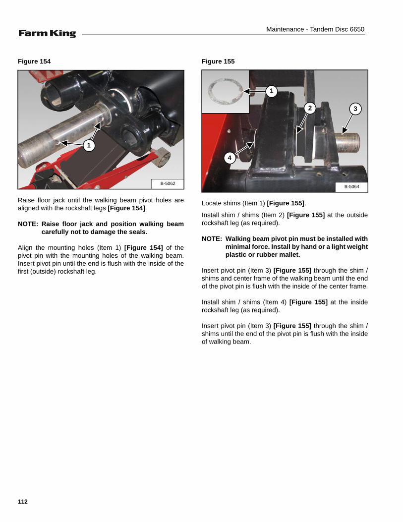
Maintenance - Tandem Disc 6650
Figure 154
Raise floor jack until the walking beam pivot holes arealigned with the rockshaft legs [Figure 154].
NOTE: Raise floor jack and position walking beamcarefully not to damage the seals.
Align the mounting holes (Item 1) [Figure 154] of thepivot pin with the mounting holes of the walking beam.Insert pivot pin until the end is flush with the inside of thefirst (outside) rockshaft leg.
Figure 155
Locate shims (Item 1) [Figure 155].
Install shim / shims (Item 2) [Figure 155] at the outsiderockshaft leg (as required).
NOTE: Walking beam pivot pin must be installed withminimal force. Install by hand or a light weightplastic or rubber mallet.
Insert pivot pin (Item 3) [Figure 155] through the shim /shims and center frame of the walking beam until the endof the pivot pin is flush with the inside of the center frame.
Install shim / shims (Item 4) [Figure 155] at the insiderockshaft leg (as required).
Insert pivot pin (Item 3) [Figure 155] through the shim /shims until the end of the pivot pin is flush with the insideof walking beam.
B-5062
1
B-5064
1
2 3
4
112
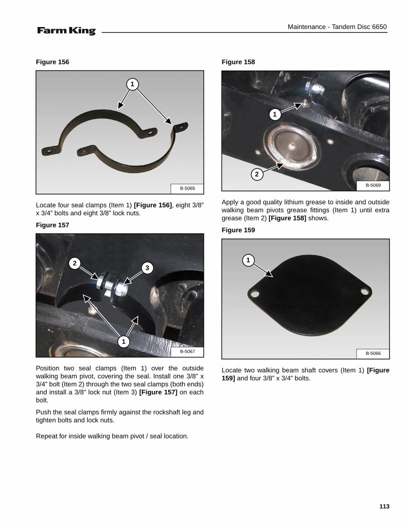
Maintenance - Tandem Disc 6650
Figure 156
Locate four seal clamps (Item 1) [Figure 156], eight 3/8”x 3/4” bolts and eight 3/8” lock nuts.
Figure 157
Position two seal clamps (Item 1) over the outsidewalking beam pivot, covering the seal. Install one 3/8” x3/4” bolt (Item 2) through the two seal clamps (both ends)and install a 3/8” lock nut (Item 3) [Figure 157] on eachbolt.
Push the seal clamps firmly against the rockshaft leg andtighten bolts and lock nuts.
Repeat for inside walking beam pivot / seal location.
Figure 158
Apply a good quality lithium grease to inside and outsidewalking beam pivots grease fittings (Item 1) until extragrease (Item 2) [Figure 158] shows.
Figure 159
Locate two walking beam shaft covers (Item 1) [Figure159] and four 3/8” x 3/4” bolts.
B-5065
1
B-5067
1
23
B-5069
2
1
B-5066
1
113
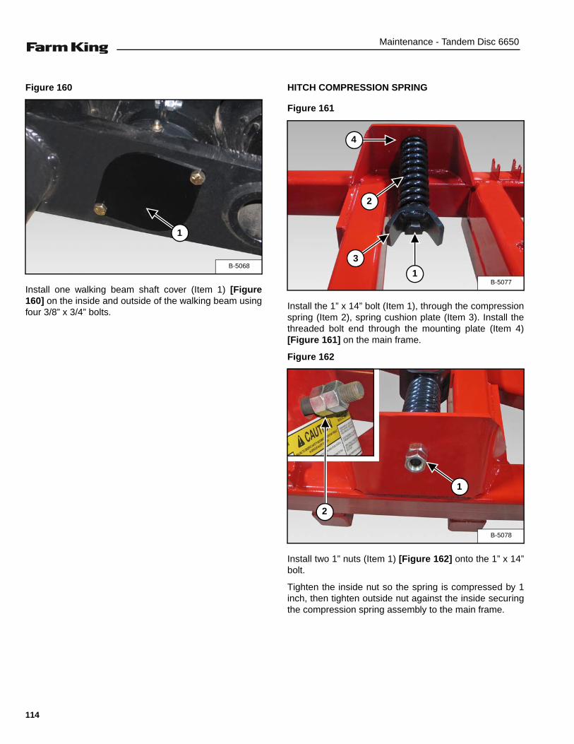
Maintenance - Tandem Disc 6650
Figure 160
Install one walking beam shaft cover (Item 1) [Figure160] on the inside and outside of the walking beam usingfour 3/8” x 3/4” bolts.
HITCH COMPRESSION SPRING
Figure 161
Install the 1” x 14” bolt (Item 1), through the compressionspring (Item 2), spring cushion plate (Item 3). Install thethreaded bolt end through the mounting plate (Item 4)[Figure 161] on the main frame.
Figure 162
Install two 1” nuts (Item 1) [Figure 162] onto the 1” x 14”bolt.
Tighten the inside nut so the spring is compressed by 1inch, then tighten outside nut against the inside securingthe compression spring assembly to the main frame.
B-5068
1
B-50771
2
3
4
B-5078
1
2
114
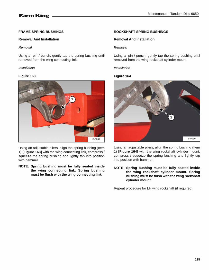
Maintenance - Tandem Disc 6650
FRAME SPRING BUSHINGS
Removal And Installation
Removal
Using a pin / punch, gently tap the spring bushing untilremoved from the wing connecting link.
Installation
Figure 163
Using an adjustable pliers, align the spring bushing (Item1) [Figure 163] with the wing connecting link, compress /squeeze the spring bushing and lightly tap into positionwith hammer.
NOTE: Spring bushing must be fully seated insidethe wing connecting link. Spring bushingmust be flush with the wing connecting link.
ROCKSHAFT SPRING BUSHINGS
Removal And Installation
Removal
Using a pin / punch, gently tap the spring bushing untilremoved from the wing rockshaft cylinder mount.
Installation
Figure 164
Using an adjustable pliers, align the spring bushing (Item1) [Figure 164] with the wing rockshaft cylinder mount,compress / squeeze the spring bushing and lightly tapinto position with hammer.
NOTE: Spring bushing must be fully seated insidethe wing rockshaft cylinder mount. Springbushing must be flush with the wing rockshaftcylinder mount.
Repeat procedure for LH wing rockshaft (if required).
B-5092
1
B-5050
1
115
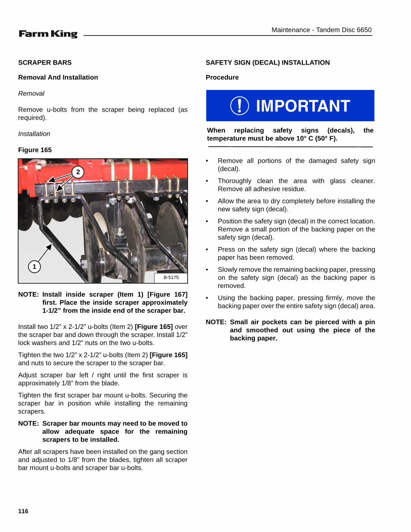
Maintenance - Tandem Disc 6650
SCRAPER BARS
Removal And Installation
Removal
Remove u-bolts from the scraper being replaced (asrequired).
Installation
Figure 165
NOTE: Install inside scraper (Item 1) [Figure 167]first. Place the inside scraper approximately1-1/2” from the inside end of the scraper bar.
Install two 1/2” x 2-1/2” u-bolts (Item 2) [Figure 165] overthe scraper bar and down through the scraper. Install 1/2”lock washers and 1/2” nuts on the two u-bolts.
Tighten the two 1/2” x 2-1/2” u-bolts (Item 2) [Figure 165]and nuts to secure the scraper to the scraper bar.
Adjust scraper bar left / right until the first scraper isapproximately 1/8” from the blade.
Tighten the first scraper bar mount u-bolts. Securing thescraper bar in position while installing the remainingscrapers.
NOTE: Scraper bar mounts may need to be moved toallow adequate space for the remainingscrapers to be installed.
After all scrapers have been installed on the gang sectionand adjusted to 1/8” from the blades, tighten all scraperbar mount u-bolts and scraper bar u-bolts.
SAFETY SIGN (DECAL) INSTALLATION
Procedure
• Remove all portions of the damaged safety sign(decal).
• Thoroughly clean the area with glass cleaner.Remove all adhesive residue.
• Allow the area to dry completely before installing thenew safety sign (decal).
• Position the safety sign (decal) in the correct location.Remove a small portion of the backing paper on thesafety sign (decal).
• Press on the safety sign (decal) where the backingpaper has been removed.
• Slowly remove the remaining backing paper, pressingon the safety sign (decal) as the backing paper isremoved.
• Using the backing paper, pressing firmly, move thebacking paper over the entire safety sign (decal) area.
NOTE: Small air pockets can be pierced with a pinand smoothed out using the piece of thebacking paper.
B-5175
1
2
When replacing safety signs (decals), thetemperature must be above 10° C (50° F).
116
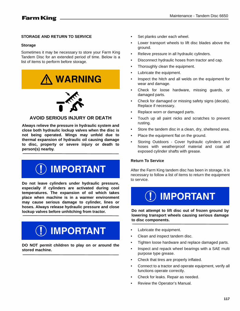
Maintenance - Tandem Disc 6650
STORAGE AND RETURN TO SERVICE
Storage
Sometimes it may be necessary to store your Farm KingTandem Disc for an extended period of time. Below is alist of items to perform before storage.
• Set planks under each wheel.
• Lower transport wheels to lift disc blades above theground.
• Relieve pressure in all hydraulic cylinders.
• Disconnect hydraulic hoses from tractor and cap.
• Thoroughly clean the equipment.
• Lubricate the equipment.
• Inspect the hitch and all welds on the equipment forwear and damage.
• Check for loose hardware, missing guards, ordamaged parts.
• Check for damaged or missing safety signs (decals).Replace if necessary.
• Replace worn or damaged parts.
• Touch up all paint nicks and scratches to preventrusting.
• Store the tandem disc in a clean, dry, sheltered area.
• Place the equipment flat on the ground.
• Storing Outdoors - Cover hydraulic cylinders andhoses with weatherproof material and coat allexposed cylinder shafts with grease.
Return To Service
After the Farm King tandem disc has been in storage, it isnecessary to follow a list of items to return the equipmentto service.
• Lubricate the equipment.
• Clean and inspect tandem disc.
• Tighten loose hardware and replace damaged parts.
• Inspect and repack wheel bearings with a SAE multipurpose type grease.
• Check that tires are properly inflated.
• Connect to a tractor and operate equipment, verify allfunctions operate correctly.
• Check for leaks. Repair as needed.
• Review the Operator’s Manual.
AVOID SERIOUS INJURY OR DEATH
Always relieve the pressure in hydraulic system andclose both hydraulic lockup valves when the disc isnot being operated. Wings may unfold due tothermal expansion of hydraulic oil causing damageto disc, property or severe injury or death toperson(s) nearby.
Do not leave cylinders under hydraulic pressure,especially if cylinders are activated during cooltemperatures. The expansion of oil which takesplace when machine is in a warmer environmentmay cause serious damage to cylinder, lines orhoses. Always release hydraulic pressure and closelockup valves before unhitching from tractor.
DO NOT permit children to play on or around thestored machine.
Do not attempt to lift disc out of frozen ground bylowering transport wheels causing serious damageto disc components.
117

Maintenance - Tandem Disc 6650
118

Parts Identification - Tandem Disc 6650
PARTS IDENTIFICATION(Models after 04.01.2013 w/ serial number 54248 and higher.)
GENERAL INFORMATION . . . . . . . . . . . . . . . . . . . . . . . . . . . . . . . . . . . . . . . . . . . . . . . . . . . . . . 123Gang Socket . . . . . . . . . . . . . . . . . . . . . . . . . . . . . . . . . . . . . . . . . . . . . . . . . . . . . . . . . . . . . . . 123Hydraulic Hose Bracket . . . . . . . . . . . . . . . . . . . . . . . . . . . . . . . . . . . . . . . . . . . . . . . . . . . . . . . 124Hitch And Crank Assembly - Narrow Wing Frame . . . . . . . . . . . . . . . . . . . . . . . . . . . . . . . . . .126Hitch And Crank Assembly - Wide Wing Frame . . . . . . . . . . . . . . . . . . . . . . . . . . . . . . . . . . . . 128Leveling Crank Assembly - Narrow Wing Frame . . . . . . . . . . . . . . . . . . . . . . . . . . . . . . . . . . . . 130Leveling Crank Assembly - Wide Wing Frame . . . . . . . . . . . . . . . . . . . . . . . . . . . . . . . . . . . . . 131Hub And Spindle Assembly - Main Frame . . . . . . . . . . . . . . . . . . . . . . . . . . . . . . . . . . . . . . . . 132Hub And Spindle Assembly- Wing Frame . . . . . . . . . . . . . . . . . . . . . . . . . . . . . . . . . . . . . . . . . 133Hydraulic Components - Narrow Wing Frame . . . . . . . . . . . . . . . . . . . . . . . . . . . . . . . . . . . . . 134Hydraulic Plumbing - Narrow Wing Frame . . . . . . . . . . . . . . . . . . . . . . . . . . . . . . . . . . . . . . . . 136Hydraulic Components - Wide Wing Frame . . . . . . . . . . . . . . . . . . . . . . . . . . . . . . . . . . . . . . . 138Hydraulic Plumbing - Wide Wing Frame . . . . . . . . . . . . . . . . . . . . . . . . . . . . . . . . . . . . . . . . . . 140Main Frame Assembly . . . . . . . . . . . . . . . . . . . . . . . . . . . . . . . . . . . . . . . . . . . . . . . . . . . . . . .142Rockshaft Assembly - Main Frame . . . . . . . . . . . . . . . . . . . . . . . . . . . . . . . . . . . . . . . . . . . . . . 144Rockshaft Assembly - Wing Frame . . . . . . . . . . . . . . . . . . . . . . . . . . . . . . . . . . . . . . . . . . . . . . 146Wing Frame Assembly - Narrow Wing Frame . . . . . . . . . . . . . . . . . . . . . . . . . . . . . . . . . . . . . .147Wing Frame Assembly - Wide Wing Frame . . . . . . . . . . . . . . . . . . . . . . . . . . . . . . . . . . . . . . . 148Gang Beam Extensions . . . . . . . . . . . . . . . . . . . . . . . . . . . . . . . . . . . . . . . . . . . . . . . . . . . . . . 149Tire Assembly . . . . . . . . . . . . . . . . . . . . . . . . . . . . . . . . . . . . . . . . . . . . . . . . . . . . . . . . . . . . . . 150Walking Beams Assembly . . . . . . . . . . . . . . . . . . . . . . . . . . . . . . . . . . . . . . . . . . . . . . . . . . . . . 152Disc Gang - 9 In. & 10.5 In. Spacing (W / Standard Hangers for 410WSS Bearings) . . . . . . . 153Scraper Assembly (9 In. Spacing) . . . . . . . . . . . . . . . . . . . . . . . . . . . . . . . . . . . . . . . . . . . . . . 154Scraper Assembly (10.5 In. Spacing) . . . . . . . . . . . . . . . . . . . . . . . . . . . . . . . . . . . . . . . . . . . . 156Gang Assembly, 9 In. Spacing (W / Rigid Hangers for 410WSS Bearings) . . . . . . . . . . . . . . . 158Gang Assembly, 10.5 In. Spacing (W / Rigid Hangers for 410WSS Bearings) . . . . . . . . . . . . . 160Gang Assembly, 10.5 In. Spacing (W / Rigid Hangers for T2 - 215 Bearings) . . . . . . . . . . . . . 162Gang Assembly, 10.5 In. Spacing (W / Rigid Hangers for T2 - 215 Bearings & Interlocking Half Spools) . . . . . . . . . . . . . . . . . . . . . . . . . . . . . . . . . . . . . . . . . . . . . . . . . . . . . . . . . . . . . . . . . . . 164Stone Flex Hanger Assembly . . . . . . . . . . . . . . . . . . . . . . . . . . . . . . . . . . . . . . . . . . . . . . . . . . 166T2 - 215 Bearing Assembly . . . . . . . . . . . . . . . . . . . . . . . . . . . . . . . . . . . . . . . . . . . . . . . . . . . .167T2-215 Bearing Assembly, 7-3/16 In. Sleeve . . . . . . . . . . . . . . . . . . . . . . . . . . . . . . . . . . . . . . 168T2-215 Bearing Assembly, 9 In. Sleeve . . . . . . . . . . . . . . . . . . . . . . . . . . . . . . . . . . . . . . . . . . 169Warning Light Assembly . . . . . . . . . . . . . . . . . . . . . . . . . . . . . . . . . . . . . . . . . . . . . . . . . . . . . . 170Main Rockshaft Cylinder - 4 In. x 24 In. (101.6 x 610 mm) . . . . . . . . . . . . . . . . . . . . . . . . . . . . 171Main Rockshaft Cylinder Seal Kit . . . . . . . . . . . . . . . . . . . . . . . . . . . . . . . . . . . . . . . . . . . . . . . 171LH Wing Rockshaft Cylinder - 3-1/2 In. x 24 In. (88.9 x 610 mm) . . . . . . . . . . . . . . . . . . . . . . . 172LH Rockshaft Cylinder Seal Kit . . . . . . . . . . . . . . . . . . . . . . . . . . . . . . . . . . . . . . . . . . . . . . . . . 172RH Wing Rockshaft Cylinder - 3 In. x 24 In. (76.2 x 610 mm) . . . . . . . . . . . . . . . . . . . . . . . . . 173RH Rockshaft Cylinder Seal Kit . . . . . . . . . . . . . . . . . . . . . . . . . . . . . . . . . . . . . . . . . . . . . . . .173Wing Lift Cylinder - 4 In. x 36 In. (102 x 914 mm) . . . . . . . . . . . . . . . . . . . . . . . . . . . . . . . . . . . 174Wing Lift Cylinder Seal Kit - 4 In. x 36 In. (102 x 914 mm) . . . . . . . . . . . . . . . . . . . . . . . . . . . . 174Wing Lift Cylinder - 5 In. x 36 In. (127 x 914 mm) . . . . . . . . . . . . . . . . . . . . . . . . . . . . . . . . . . . 175Wing Lift Cylinder Seal Kit - 5 In. x 36 In. (127 x 914 mm) . . . . . . . . . . . . . . . . . . . . . . . . . . . . 176
119

Parts Identification - Tandem Disc 6650
120

Parts - Tandem Disc 6650
GENERAL INFORMATION
The parts identification section lists descriptions, part numbers and quantities for the 6650 Tandem Disc. Contactyour Farm King dealer for additional 6650 Tandem Disc parts information.
Gang Socket
ITEM PART NUMBER DESCRIPTION QTY
1 EZDGA35 SOCKET-W.A. WRENCH 1
88706298
1
121
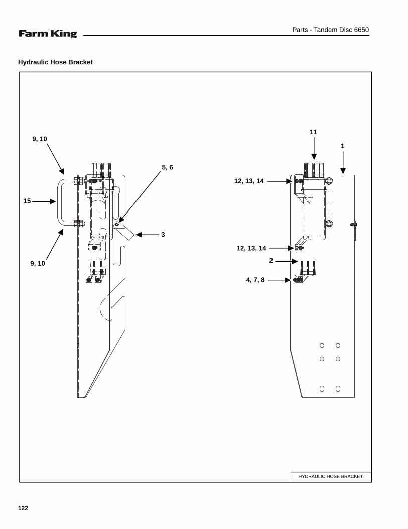
Parts - Tandem Disc 6650
Hydraulic Hose Bracket
HYDRAULIC HOSE BRACKET
9, 10
9, 10
15
5, 6
3
4, 7, 8
2
12, 13, 14
12, 13, 14
1
11
122
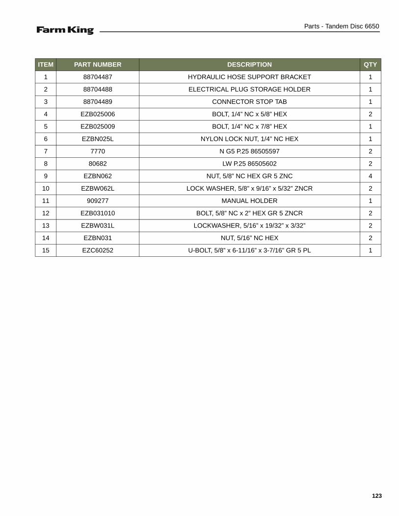
Parts - Tandem Disc 6650
ITEM PART NUMBER DESCRIPTION QTY
1 88704487 HYDRAULIC HOSE SUPPORT BRACKET 1
2 88704488 ELECTRICAL PLUG STORAGE HOLDER 1
3 88704489 CONNECTOR STOP TAB 1
4 EZB025006 BOLT, 1/4” NC x 5/8” HEX 2
5 EZB025009 BOLT, 1/4” NC x 7/8” HEX 1
6 EZBN025L NYLON LOCK NUT, 1/4” NC HEX 1
7 7770 N G5 P.25 86505597 2
8 80682 LW P.25 86505602 2
9 EZBN062 NUT, 5/8” NC HEX GR 5 ZNC 4
10 EZBW062L LOCK WASHER, 5/8” x 9/16” x 5/32” ZNCR 2
11 909277 MANUAL HOLDER 1
12 EZB031010 BOLT, 5/8” NC x 2” HEX GR 5 ZNCR 2
13 EZBW031L LOCKWASHER, 5/16” x 19/32” x 3/32” 2
14 EZBN031 NUT, 5/16” NC HEX 2
15 EZC60252 U-BOLT, 5/8” x 6-11/16” x 3-7/16” GR 5 PL 1
123
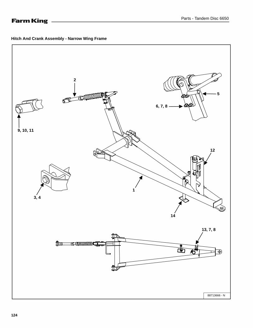
Parts - Tandem Disc 6650
Hitch And Crank Assembly - Narrow Wing Frame
88713666 - N
5
6, 7, 8
9, 10, 11
1
12
14
3, 4
2
13, 7, 8
124
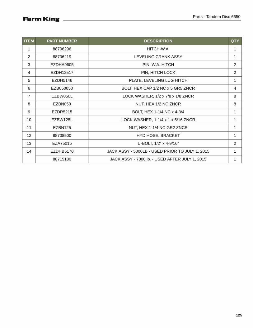
Parts - Tandem Disc 6650
ITEM PART NUMBER DESCRIPTION QTY
1 88706296 HITCH-W.A. 1
2 88706219 LEVELING CRANK ASSY 1
3 EZDHA9605 PIN, W.A. HITCH 2
4 EZDH12517 PIN, HITCH LOCK 2
5 EZDH5146 PLATE, LEVELING LUG HITCH 1
6 EZB050050 BOLT, HEX CAP 1/2 NC x 5 GR5 ZNCR 4
7 EZBW050L LOCK WASHER, 1/2 x 7/8 x 1/8 ZNCR 8
8 EZBN050 NUT, HEX 1/2 NC ZNCR 8
9 EZDR5215 BOLT, HEX 1-1/4 NC x 4-3/4 1
10 EZBW125L LOCK WASHER, 1-1/4 x 1 x 5/16 ZNCR 1
11 EZBN125 NUT, HEX 1-1/4 NC GR2 ZNCR 1
12 88708500 HYD HOSE, BRACKET 1
13 EZA75015 U-BOLT, 1/2” x 4-9/16” 2
14 EZDHB5170 JACK ASSY - 5000LB - USED PRIOR TO JULY 1, 2015 1
88715180 JACK ASSY - 7000 lb. - USED AFTER JULY 1, 2015 1
125

Parts - Tandem Disc 6650
Hitch And Crank Assembly - Wide Wing Frame
88715409 - W
5
6, 7, 8
9, 10, 11
1
12
14
3, 4
2
13, 7, 8
126
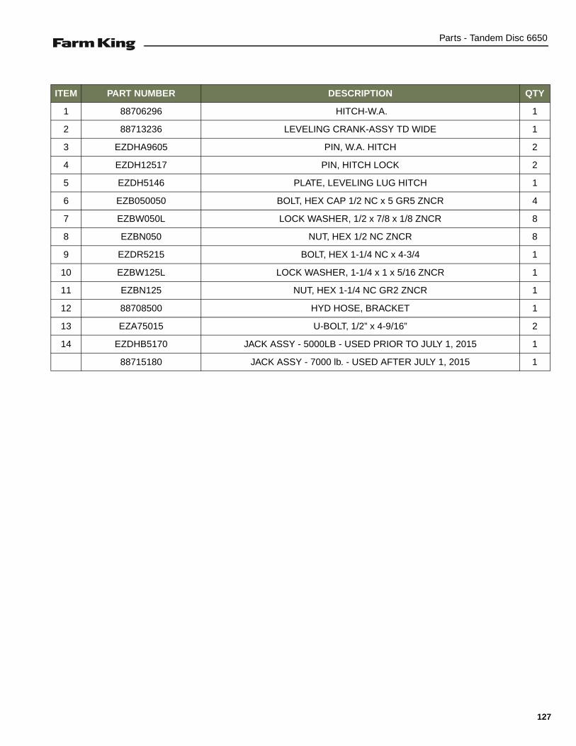
Parts - Tandem Disc 6650
ITEM PART NUMBER DESCRIPTION QTY
1 88706296 HITCH-W.A. 1
2 88713236 LEVELING CRANK-ASSY TD WIDE 1
3 EZDHA9605 PIN, W.A. HITCH 2
4 EZDH12517 PIN, HITCH LOCK 2
5 EZDH5146 PLATE, LEVELING LUG HITCH 1
6 EZB050050 BOLT, HEX CAP 1/2 NC x 5 GR5 ZNCR 4
7 EZBW050L LOCK WASHER, 1/2 x 7/8 x 1/8 ZNCR 8
8 EZBN050 NUT, HEX 1/2 NC ZNCR 8
9 EZDR5215 BOLT, HEX 1-1/4 NC x 4-3/4 1
10 EZBW125L LOCK WASHER, 1-1/4 x 1 x 5/16 ZNCR 1
11 EZBN125 NUT, HEX 1-1/4 NC GR2 ZNCR 1
12 88708500 HYD HOSE, BRACKET 1
13 EZA75015 U-BOLT, 1/2” x 4-9/16” 2
14 EZDHB5170 JACK ASSY - 5000LB - USED PRIOR TO JULY 1, 2015 1
88715180 JACK ASSY - 7000 lb. - USED AFTER JULY 1, 2015 1
127
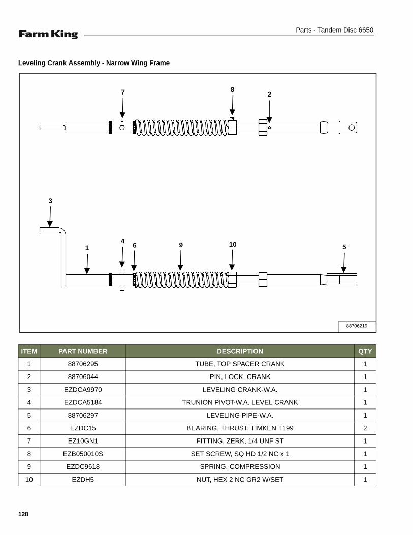
Parts - Tandem Disc 6650
Leveling Crank Assembly - Narrow Wing Frame
ITEM PART NUMBER DESCRIPTION QTY
1 88706295 TUBE, TOP SPACER CRANK 1
2 88706044 PIN, LOCK, CRANK 1
3 EZDCA9970 LEVELING CRANK-W.A. 1
4 EZDCA5184 TRUNION PIVOT-W.A. LEVEL CRANK 1
5 88706297 LEVELING PIPE-W.A. 1
6 EZDC15 BEARING, THRUST, TIMKEN T199 2
7 EZ10GN1 FITTING, ZERK, 1/4 UNF ST 1
8 EZB050010S SET SCREW, SQ HD 1/2 NC x 1 1
9 EZDC9618 SPRING, COMPRESSION 1
10 EZDH5 NUT, HEX 2 NC GR2 W/SET 1
88706219
7
51
8
4
3
106 9
2
128
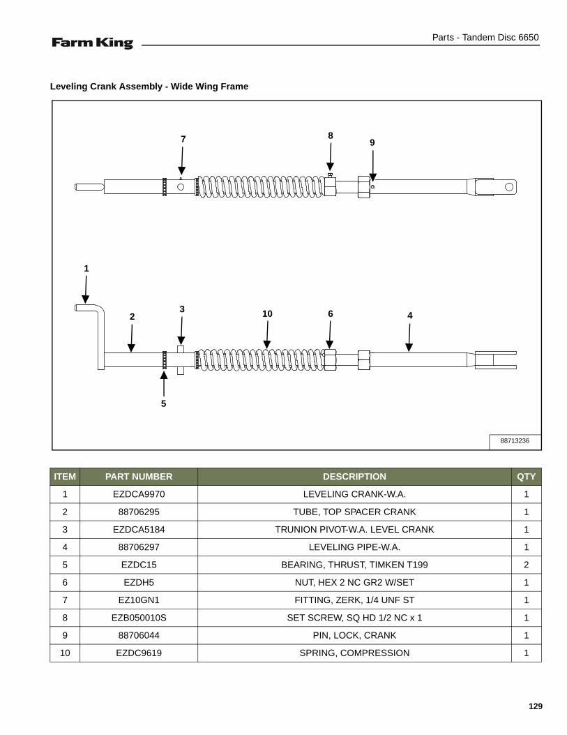
Parts - Tandem Disc 6650
Leveling Crank Assembly - Wide Wing Frame
ITEM PART NUMBER DESCRIPTION QTY
1 EZDCA9970 LEVELING CRANK-W.A. 1
2 88706295 TUBE, TOP SPACER CRANK 1
3 EZDCA5184 TRUNION PIVOT-W.A. LEVEL CRANK 1
4 88706297 LEVELING PIPE-W.A. 1
5 EZDC15 BEARING, THRUST, TIMKEN T199 2
6 EZDH5 NUT, HEX 2 NC GR2 W/SET 1
7 EZ10GN1 FITTING, ZERK, 1/4 UNF ST 1
8 EZB050010S SET SCREW, SQ HD 1/2 NC x 1 1
9 88706044 PIN, LOCK, CRANK 1
10 EZDC9619 SPRING, COMPRESSION 1
88713236
7 8
1
23
5
10 6 4
9
129

Parts - Tandem Disc 6650
Hub And Spindle Assembly - Main Frame
ITEM PART NUMBER DESCRIPTION QTY
1 EZBP18125 PIN, COTTER, 3/16” x 1-1/4” 1
2 EZBW20010612F FLAT WASHER, 1-1/16” x 2” x 1/8” 1
3 EZDR110 NUT, HEX SLOT 1-14 NS GR5 ZNCR 1
4 88712587 SPINDLE-812 16-3/4” x 3-1/2” OD 1
5 EZDR9684 BEARING CONE, 3780 1
6 EZDR9685 BEARING CONE, 2790 1
7 EZDRA9679 HUB-ASSY W/CUPS 8 BOLT 1
8 EZDR9681 HUB CAP 1
9 DR13200 HUB SEAL CUP, 8 BOLT 1
10 DR13201 HUB SEAL, 8 BOLT (812) 1
11 EZ10GN1 STRAIGHT GREASE FITTING, 1/4” - 28 1
88712588
1
8 75
4
3
2
6
9
10
11
130

Parts - Tandem Disc 6650
Hub And Spindle Assembly- Wing Frame
ITEM PART NUMBER DESCRIPTION QTY
1 EZBP18125 PIN, COTTER, 3/16 x 1-1/4 1
2 EZBW20010612F WASHER, FLAT, 1-1/16 x 2 x 1/8 1
3 EZDR110 NUT, HEX SLOT 1-14 NS GR5 ZNCR 1
4 EZDR13004 SPINDLE-812 13-3/4 1
5 EZDR9684 BEARING CONE, 3780 1
6 EZDR9685 BEARING CONE, 2790 1
7 EZDRA9679 HUB-ASSY W/CUPS 8 BOLT 1
8 EZDR9681 HUB CAP 1
9 DR13200 HUB SEAL CUP, 8 BOLT 1
10 DR13201 HUB SEAL, 8 BOLT (812) 1
11 EZ10GN1 STRAIGHT GREASE FITTING, 1/4” - 28 1
88712617
1
87
5 4
3
2
6
9
10
11
131

Parts - Tandem Disc 6650
Hydraulic Components - Narrow Wing Frame
HYD N SN
3
1, 2
1, 2
2, 4, 5
9
1, 2
9
1, 2
1, 2
1, 2
2, 4, 5
10
6, 7, 8
1, 2
11
12, 7, 8
13
132

Parts - Tandem Disc 6650
ITEM PART NUMBER DESCRIPTION QTY
1 EZDR5262 PIN, CYLINDER 8
2 EZBP31175 COTTER PIN, 5/16” x 1-3/4” 10
3 EZ304 CYLINDER ASSEMBLY, REPHASING 3” DIA x 24 STROKE 1
4 EZDF5068 WASHER, 1-9/32” ID x 2” OD x 1/4” 6
5 EZS81856 PIN, CYLINDER 1-1/4” x 5-13/16” LG 2
6 EZDL9771 HOSE RETAINER 6
7 EZBW050L LOCK WASHER, 1/2” ZNCR 9
8 EZB050007 BOLT, CSHH G5 P 1/2” x 3/4” 9
9 EZ248 WING LIFT CYLINDER, 4” x 36” 2
10 EZ306 CYLINDER ASSEMBLY, REPHASING 4” DIA x 24” STROKE 1
11 EZ305 CYLINDER ASSEMBLY, REPHASING 3-1/2” DIA x 24” STROKE 1
12 EZDL13186 HOSE CLAMP, 4 LINE 3
13 EZDL13099 BALL VALVE, GE2 - N 3/8” 2 WAY 2
133
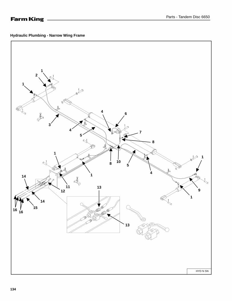
Parts - Tandem Disc 6650
Hydraulic Plumbing - Narrow Wing Frame
HYD N SN
3
2
1
1
1
1
4
1
11
4 6
7
8
5
5
4
9
8 10
1
13
13
14
14
12
16 1615
134
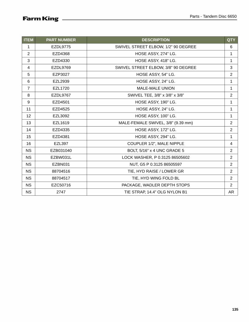
Parts - Tandem Disc 6650
ITEM PART NUMBER DESCRIPTION QTY
1 EZDL9775 SWIVEL STREET ELBOW, 1/2” 90 DEGREE 6
2 EZD4368 HOSE ASSY, 274” LG. 1
3 EZD4330 HOSE ASSY, 418” LG. 1
4 EZDL9769 SWIVEL STREET ELBOW, 3/8” 90 DEGREE 3
5 EZP3027 HOSE ASSY, 54” LG. 2
6 EZL2939 HOSE ASSY, 24” LG. 1
7 EZL1720 MALE-MALE UNION 1
8 EZDL9767 SWIVEL TEE, 3/8” x 3/8” x 3/8” 2
9 EZD4501 HOSE ASSY, 190” LG. 1
11 EZD4525 HOSE ASSY, 24” LG. 1
12 EZL3092 HOSE ASSY, 100” LG. 1
13 EZL1619 MALE-FEMALE SWIVEL, 3/8” (9.39 mm) 2
14 EZD4335 HOSE ASSY, 172” LG. 2
15 EZD4381 HOSE ASSY, 294” LG. 1
16 EZL397 COUPLER 1/2”, MALE NIPPLE 4
NS EZB031040 BOLT, 5/16” x 4 UNC GRADE 5 2
NS EZBW031L LOCK WASHER, P 0.3125 86505602 2
NS EZBN031 NUT, G5 P 0.3125 86505597 2
NS 88704516 TIE, HYD RAISE / LOWER GR 2
NS 88704517 TIE, HYD WING FOLD BL 2
NS EZC50716 PACKAGE, WADLER DEPTH STOPS 2
NS 2747 TIE STRAP, 14.4” OLG NYLON B1 AR
135

Parts - Tandem Disc 6650
Hydraulic Components - Wide Wing Frame
HYD N SN
3
1, 2
1, 2
2, 4, 5
9
1, 2
9
1, 2
1, 2
1, 2
2, 4, 5
10
6, 7, 8
1, 2
11
12, 7, 8
13
136

Parts - Tandem Disc 6650
ITEM PART NUMBER DESCRIPTION QTY
1 EZDR5262 PIN, CYLINDER 8
2 EZBP31175 COTTER PIN, 5/16” x 1-3/4” 10
3 EZ304 CYLINDER ASSEMBLY, REPHASING 3” DIA x 24 STROKE 1
4 EZDF5068 WASHER, 1-9/32” ID x 2” OD x 1/4” 6
5 EZS81856 PIN, CYLINDER 1-1/4” x 5-13/16” LG 2
6 EZDL9771 HOSE RETAINER 6
7 EZBW050L LOCK WASHER, 1/2” ZNCR 9
8 EZB050007 BOLT, CSHH G5 P 1/2” x 3/4” 9
9 EZ332 WING LIFT CYLINDER, 5” x 36” 2
10 EZ306 CYLINDER ASSEMBLY, REPHASING 4” DIA x 24” STROKE 1
11 EZ305 CYLINDER ASSEMBLY, REPHASING 3-1/2” DIA x 24” STROKE 1
12 EZDL13186 HOSE CLAMP, 4 LINE 3
13 EZDL13099 BALL VALVE, GE2 - N 3/8” 2 WAY 2
137
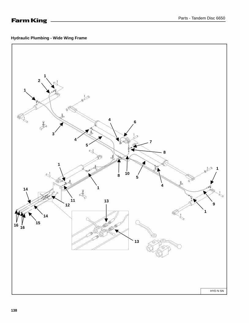
Parts - Tandem Disc 6650
Hydraulic Plumbing - Wide Wing Frame
HYD N SN
3
2
1
1
1
1
4
1
11
4 6
7
8
5
5
4
9
8 10
1
13
13
14
14
12
16 1615
138

Parts - Tandem Disc 6650
ITEM PART NUMBER DESCRIPTION QTY
1 EZDL9775 SWIVEL STREET ELBOW, 1/2” 90 DEGREE 6
2 EZD4481 HOSE ASSY, 334” LG. 1
3 EZD4479 HOSE ASSY, 440” LG. 1
4 EZDL9769 SWIVEL STREET ELBOW, 3/8” 90 DEGREE 3
5 EZP3027 HOSE ASSY, 54” LG. 2
6 EZL2939 HOSE ASSY, 24” LG. 1
7 EZL1720 MALE-MALE UNION 1
8 EZDL9767 SWIVEL TEE, 3/8” x 3/8” x 3/8” 2
9 EZD4483 HOSE ASSY, 220” LG. 1
11 EZD4336 HOSE ASSY, 20” LG. 1
12 EZL4344 HOSE ASSY, 106” LG. 1
13 EZL1619 MALE-FEMALE SWIVEL, 3/8” (9.39 mm) 2
14 EZD4382 HOSE ASSY, 179” LG. 2
15 EZD4381 HOSE ASSY, 294” LG. 1
16 EZL397 COUPLER 1/2”, MALE NIPPLE 4
NS EZB031040 BOLT, 5/16” x 4 UNC GRADE 5 2
NS EZBW031L LOCK WASHER, P 0.3125 86505602 2
NS EZBN031 NUT, G5 P 0.3125 86505597 2
NS 88704516 TIE, HYD RAISE / LOWER GR 2
NS 88704517 TIE, HYD WING FOLD BL 2
NS EZC50716 PACKAGE, WADLER DEPTH STOPS 2
NS 2747 TIE STRAP, 14.4” OLG NYLON B1 AR
139
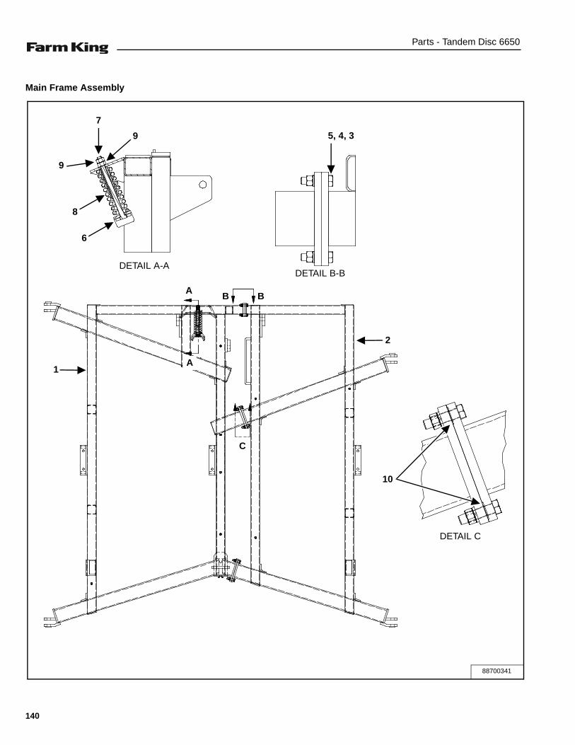
Parts - Tandem Disc 6650
Main Frame Assembly
C
88700341
7
9
8
6
1
9
2
5, 4, 3
10
DETAIL A-A
A
AB B
DETAIL B-B
C
DETAIL C
140

Parts - Tandem Disc 6650
ITEM PART NUMBER DESCRIPTION QTY
1 88706143 FRAME-W.A. MN TD600 L/H RED 1
2 88706144 FRAME-W.A. MN TD600 R/H RED 1
3 EZBN075 NUT, 0.75” G5 P 86505597 12
4 EZBW075L LOCK WASHER, 0.75” P 86505602 12
5 EZB075030 BOLT, CSHH G5P 0.75” x 3.0” 86505344 12
6 EZDFA10536 PLATE, W.A. SPRING CUSHION 1
7 EZB100140 BOLT, HEX 1”-8 NC x 14” 1
8 EZDC9615 SPRING, COMPRESSION 1
9 EZBN100 NUT, HEX GR5 ZNCR 1”-8 2
10 88713355 PLATE, SHIM MAIN FRAME AR
141
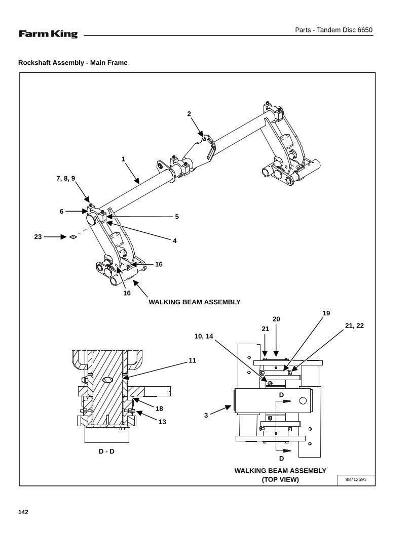
Parts - Tandem Disc 6650
Rockshaft Assembly - Main Frame
88712591
D
D
2
D - D
1
7, 8, 9
65
4
16
16
11
18
13
10, 14
3
2120
19
21, 22
23
WALKING BEAM ASSEMBLY
WALKING BEAM ASSEMBLY(TOP VIEW)
142
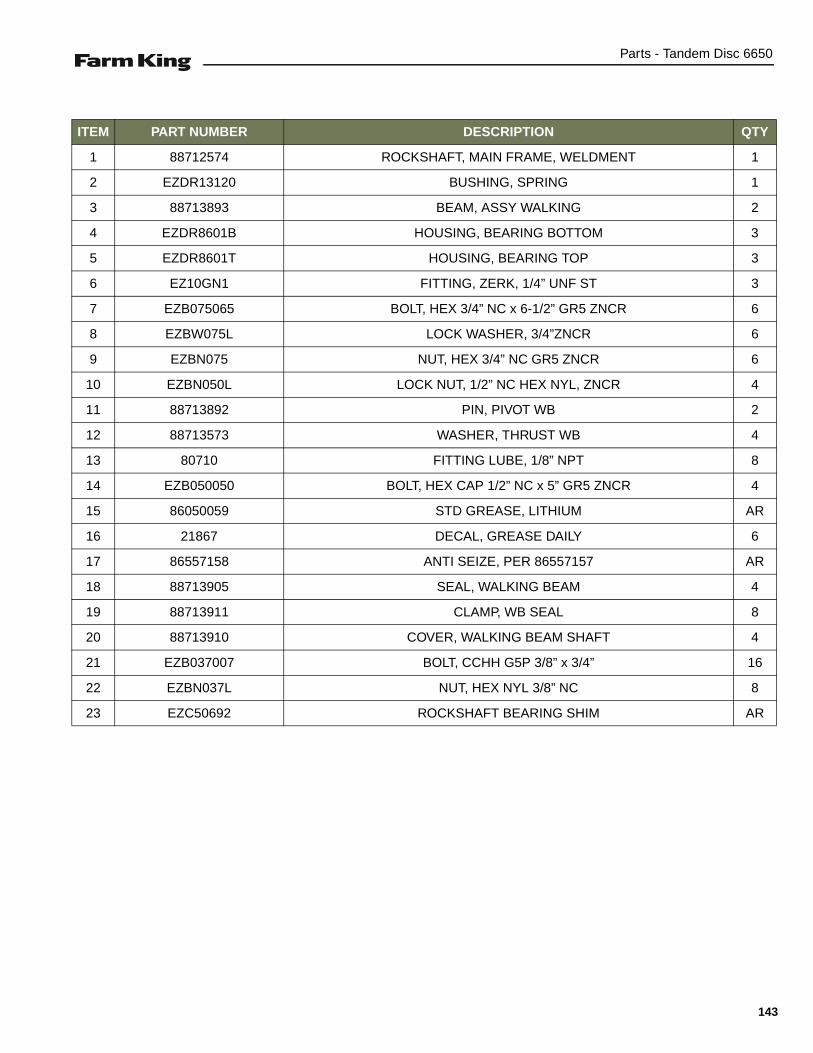
Parts - Tandem Disc 6650
ITEM PART NUMBER DESCRIPTION QTY
1 88712574 ROCKSHAFT, MAIN FRAME, WELDMENT 1
2 EZDR13120 BUSHING, SPRING 1
3 88713893 BEAM, ASSY WALKING 2
4 EZDR8601B HOUSING, BEARING BOTTOM 3
5 EZDR8601T HOUSING, BEARING TOP 3
6 EZ10GN1 FITTING, ZERK, 1/4” UNF ST 3
7 EZB075065 BOLT, HEX 3/4” NC x 6-1/2” GR5 ZNCR 6
8 EZBW075L LOCK WASHER, 3/4”ZNCR 6
9 EZBN075 NUT, HEX 3/4” NC GR5 ZNCR 6
10 EZBN050L LOCK NUT, 1/2” NC HEX NYL, ZNCR 4
11 88713892 PIN, PIVOT WB 2
12 88713573 WASHER, THRUST WB 4
13 80710 FITTING LUBE, 1/8” NPT 8
14 EZB050050 BOLT, HEX CAP 1/2” NC x 5” GR5 ZNCR 4
15 86050059 STD GREASE, LITHIUM AR
16 21867 DECAL, GREASE DAILY 6
17 86557158 ANTI SEIZE, PER 86557157 AR
18 88713905 SEAL, WALKING BEAM 4
19 88713911 CLAMP, WB SEAL 8
20 88713910 COVER, WALKING BEAM SHAFT 4
21 EZB037007 BOLT, CCHH G5P 3/8” x 3/4” 16
22 EZBN037L NUT, HEX NYL 3/8” NC 8
23 EZC50692 ROCKSHAFT BEARING SHIM AR
143
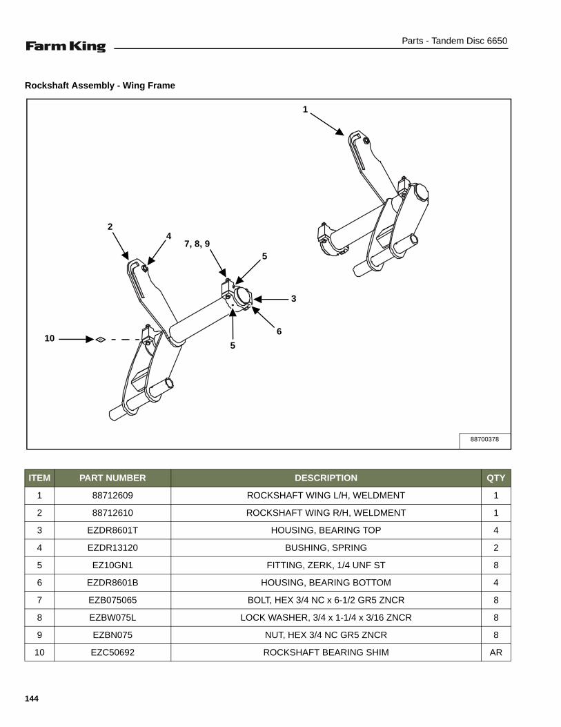
Parts - Tandem Disc 6650
Rockshaft Assembly - Wing Frame
ITEM PART NUMBER DESCRIPTION QTY
1 88712609 ROCKSHAFT WING L/H, WELDMENT 1
2 88712610 ROCKSHAFT WING R/H, WELDMENT 1
3 EZDR8601T HOUSING, BEARING TOP 4
4 EZDR13120 BUSHING, SPRING 2
5 EZ10GN1 FITTING, ZERK, 1/4 UNF ST 8
6 EZDR8601B HOUSING, BEARING BOTTOM 4
7 EZB075065 BOLT, HEX 3/4 NC x 6-1/2 GR5 ZNCR 8
8 EZBW075L LOCK WASHER, 3/4 x 1-1/4 x 3/16 ZNCR 8
9 EZBN075 NUT, HEX 3/4 NC GR5 ZNCR 8
10 EZC50692 ROCKSHAFT BEARING SHIM AR
88700378
7, 8, 95
3
1
2
6
5
4
10
144

Parts - Tandem Disc 6650
Wing Frame Assembly - Narrow Wing Frame
ITEM PART NUMBER DESCRIPTION QTY
1 88700426 FRAME-W.A. NAR WING TD600 L/H RED 1
2 88700428 FRAME-W.A. NAR WING TD600 R/H RED 1
3 EZ10GN1 FITTING, ZERK, 1/4 UNF ST 8
4 EZDH5165 NUT, HEX SLOT 1-1/2 NC GR 2 4
5 EZBP31225 PIN, COTTER, 5/16 x 2-1/4 4
6 EZBN100 NUT, HEX 1-8 NC GR 5 ZNCR 4
7 EZDFA9564 ROD-W.A. EYE BOLT 2
8 EZDG13286 BUSHING, SPRING W/OIL GROOVE 4
9 EZDG13009 PIN, WING HINGE 1-1/2 4
88700412
1 2
8
3
5
9
4
6
7
DETAIL A-A
DETAIL B
A
A
B
145

Parts - Tandem Disc 6650
Wing Frame Assembly - Wide Wing Frame
ITEM PART NUMBER DESCRIPTION QTY
1 88706145 FRAME-W.A. WING TD600 L/H RED 1
2 88706146 FRAME-W.A. WING TD600 R/H RED 1
3 EZDFA9564 ROD-W.A. EYE BOLT 2
4 EZBN100 NUT, HEX 1-8 NC GR 5 ZNCR 4
5 EZDH5165 NUT, HEX SLOT 1-1/2 NC GR 2 4
6 EZBP31225 PIN, COTTER, 5/16 x 2-1/4 4
7 EZ10GN1 FITTING, ZERK, 1/4 UNF ST 8
8 EZDG13009 PIN, WING HINGE 1-1/2 4
9 EZDG13286 BUSHING, SPRING W/OIL GROOVE 4
88700385
6
DETAIL A-A
7 7
9
5
8
4
3
DETAIL B
B
A
A
1
2
146
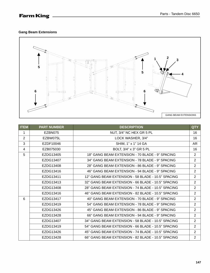
Parts - Tandem Disc 6650
Gang Beam Extensions
ITEM PART NUMBER DESCRIPTION QTY
1 EZBN075 NUT, 3/4” NC HEX GR 5 PL 16
2 EZBW075L LOCK WASHER, 3/4” 16
3 EZDF10046 SHIM, 1” x 1” 14 GA AR
4 EZB075030 BOLT, 3/4” x 3” GR 5 PL 16
5 EZDG13405 18” GANG BEAM EXTENSION - 70 BLADE - 9” SPACING 2
EZDG13407 34” GANG BEAM EXTENSION - 78 BLADE - 9” SPACING 2
EZDG13408 28” GANG BEAM EXTENSION - 86 BLADE - 9” SPACING 2
EZDG13416 46” GANG BEAM EXTENSION - 94 BLADE - 9” SPACING 2
EZDG13411 12” GANG BEAM EXTENSION - 58 BLADE - 10.5” SPACING 2
EZDG13413 32” GANG BEAM EXTENSION - 66 BLADE - 10.5” SPACING 2
EZDG13408 28” GANG BEAM EXTENSION - 74 BLADE - 10.5” SPACING 2
EZDG13416 46" GANG BEAM EXTENSION - 82 BLADE - 10.5” SPACING 2
6 EZDG13417 40” GANG BEAM EXTENSION - 70 BLADE - 9” SPACING 2
EZDG13419 54” GANG BEAM EXTENSION - 78 BLADE - 9” SPACING 2
EZDG13426 45” GANG BEAM EXTENSION - 86 BLADE - 9” SPACING 2
EZDG13428 66” GANG BEAM EXTENSION - 94 BLADE - 9” SPACING 2
EZDG13407 34” GANG BEAM EXTENSION - 58 BLADE - 10.5” SPACING 2
EZDG13419 54” GANG BEAM EXTENSION - 66 BLADE - 10.5” SPACING 2
EZDG13426 45” GANG BEAM EXTENSION - 74 BLADE - 10.5” SPACING 2
EZDG13428 66” GANG BEAM EXTENSION - 82 BLADE - 10.5” SPACING 2
GANG BEAM EXTENSIONS
1 23
45
5
6 6
147

Parts - Tandem Disc 6650
Tire Assembly
88713017
7, 2
A A B B
C
C
D
D
1, 2
9
5, 6
8
DETAIL A-A DETAIL B-B
DETAIL C-C DETAIL D-D
WING ROCKSHAFTS
WING ROCKSHAFTS
MAIN FRAME ROCKSHAFTS
MAIN FRAME ROCKSHAFTS
4
3
10
148
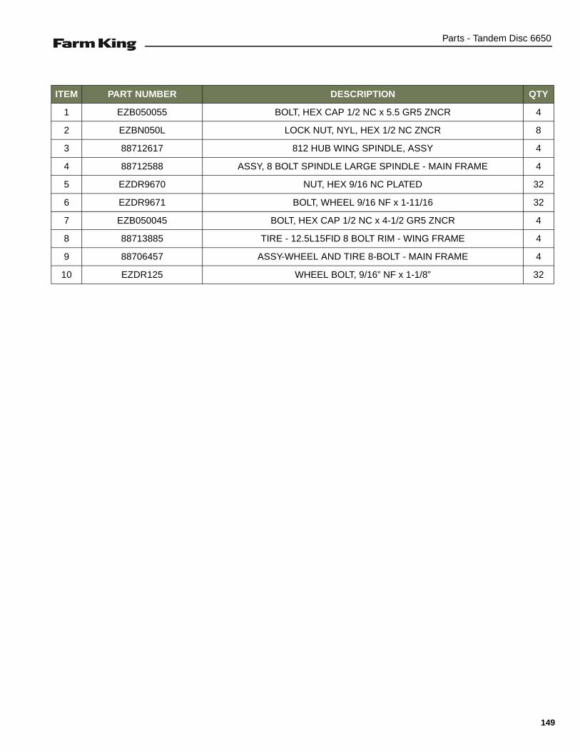
Parts - Tandem Disc 6650
ITEM PART NUMBER DESCRIPTION QTY
1 EZB050055 BOLT, HEX CAP 1/2 NC x 5.5 GR5 ZNCR 4
2 EZBN050L LOCK NUT, NYL, HEX 1/2 NC ZNCR 8
3 88712617 812 HUB WING SPINDLE, ASSY 4
4 88712588 ASSY, 8 BOLT SPINDLE LARGE SPINDLE - MAIN FRAME 4
5 EZDR9670 NUT, HEX 9/16 NC PLATED 32
6 EZDR9671 BOLT, WHEEL 9/16 NF x 1-11/16 32
7 EZB050045 BOLT, HEX CAP 1/2 NC x 4-1/2 GR5 ZNCR 4
8 88713885 TIRE - 12.5L15FID 8 BOLT RIM - WING FRAME 4
9 88706457 ASSY-WHEEL AND TIRE 8-BOLT - MAIN FRAME 4
10 EZDR125 WHEEL BOLT, 9/16” NF x 1-1/8” 32
149
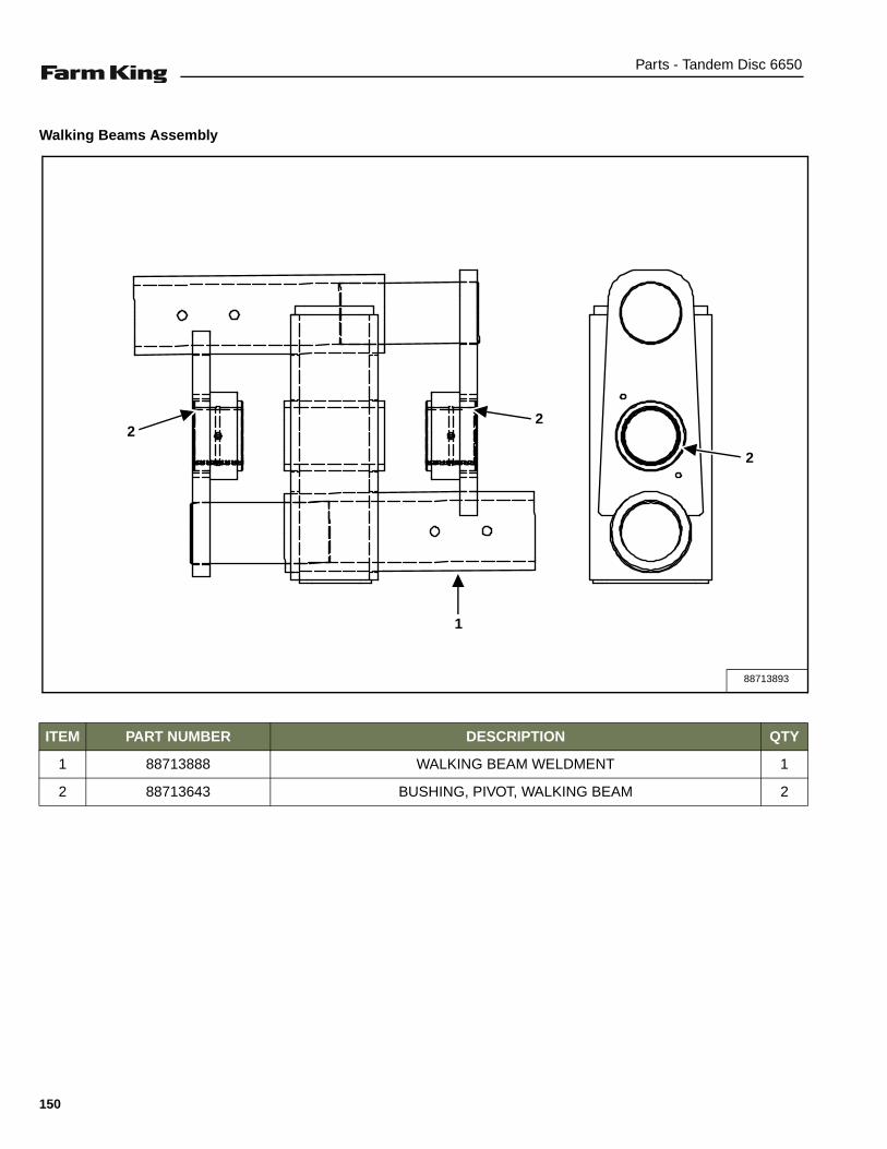
Parts - Tandem Disc 6650
Walking Beams Assembly
ITEM PART NUMBER DESCRIPTION QTY
1 88713888 WALKING BEAM WELDMENT 1
2 88713643 BUSHING, PIVOT, WALKING BEAM 2
88713893
22
2
1
150

Parts - Tandem Disc 6650
Disc Gang - 9 In. & 10.5 In. Spacing (W / Standard Hangers for 410WSS Bearings)
ITEM PART NUMBER BLADE OPTIONS - 9” SPACING - 24” BLADES QTY
1 EZDG84 Blade-Plain Outrig 16” x 0.157” *
2 EZDG149 Blade-Plain Outrig 20” x 0.236” *
3 EZDG76 Blade-Plain 24” x 0.276” *
EZDG137 Blade-Plain 24” x 0.313” *
EZDG138 Blade-Notched 24” x 0.313” *
* As Required
ITEM PART NUMBER BLADE OPTIONS - 9” SPACING - 26” BLADES QTY
1 EZDG133 Blade-Plain Outrig 18” x 0.197” *
2 EZDG64 Blade-Plain Outrig 22” x 0.250” *
3 EZDG74 Blade-Plain 26” x 0.313” *
EZDG75 Blade-Notched 26” x 0.313” *
* As Required
ITEM PART NUMBER BLADE OPTIONS - 10.5” SPACING - 26” BLADES QTY
1 EZDG133 Blade-Plain Outrig 18” x 0.197” *
2 EZDG64 Blade-Plain Outrig 22” x 0.250” *
3 EZDG74 Blade-Plain 26” x 0.313” *
EZDG75 Blade-Notched 26” x 0.313” *
EZDG107 Blade-Plain 26” x 0.375” *
EZDG87 Blade-Notched 26” x 0.375” *
* As Required
12
3
21
3
3
3
151
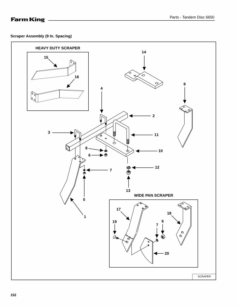
Parts - Tandem Disc 6650
Scraper Assembly (9 In. Spacing)
SCRAPER
1
5
7
13
12
10
11
4
8
6
14
9
2
15
16
1718
197
6
20
HEAVY DUTY SCRAPER
WIDE PAN SCRAPER
3
152
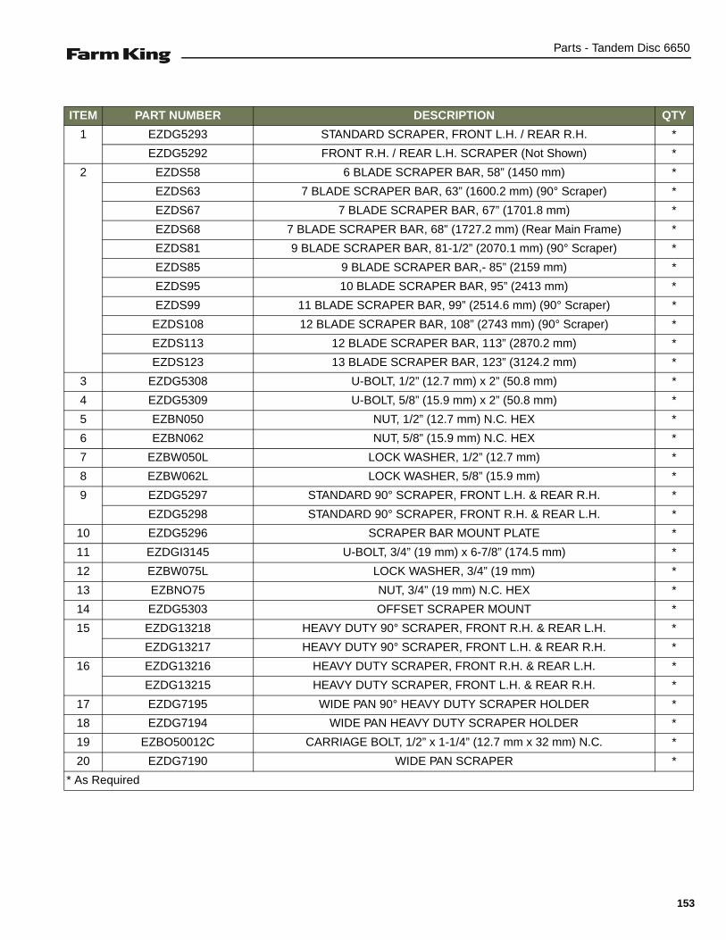
Parts - Tandem Disc 6650
ITEM PART NUMBER DESCRIPTION QTY
1 EZDG5293 STANDARD SCRAPER, FRONT L.H. / REAR R.H. *
EZDG5292 FRONT R.H. / REAR L.H. SCRAPER (Not Shown) *
2 EZDS58 6 BLADE SCRAPER BAR, 58” (1450 mm) *
EZDS63 7 BLADE SCRAPER BAR, 63” (1600.2 mm) (90° Scraper) *
EZDS67 7 BLADE SCRAPER BAR, 67” (1701.8 mm) *
EZDS68 7 BLADE SCRAPER BAR, 68” (1727.2 mm) (Rear Main Frame) *
EZDS81 9 BLADE SCRAPER BAR, 81-1/2” (2070.1 mm) (90° Scraper) *
EZDS85 9 BLADE SCRAPER BAR,- 85” (2159 mm) *
EZDS95 10 BLADE SCRAPER BAR, 95” (2413 mm) *
EZDS99 11 BLADE SCRAPER BAR, 99” (2514.6 mm) (90° Scraper) *
EZDS108 12 BLADE SCRAPER BAR, 108” (2743 mm) (90° Scraper) *
EZDS113 12 BLADE SCRAPER BAR, 113” (2870.2 mm) *
EZDS123 13 BLADE SCRAPER BAR, 123” (3124.2 mm) *
3 EZDG5308 U-BOLT, 1/2” (12.7 mm) x 2” (50.8 mm) *
4 EZDG5309 U-BOLT, 5/8” (15.9 mm) x 2” (50.8 mm) *
5 EZBN050 NUT, 1/2” (12.7 mm) N.C. HEX *
6 EZBN062 NUT, 5/8” (15.9 mm) N.C. HEX *
7 EZBW050L LOCK WASHER, 1/2” (12.7 mm) *
8 EZBW062L LOCK WASHER, 5/8” (15.9 mm) *
9 EZDG5297 STANDARD 90° SCRAPER, FRONT L.H. & REAR R.H. *
EZDG5298 STANDARD 90° SCRAPER, FRONT R.H. & REAR L.H. *
10 EZDG5296 SCRAPER BAR MOUNT PLATE *
11 EZDGI3145 U-BOLT, 3/4” (19 mm) x 6-7/8” (174.5 mm) *
12 EZBW075L LOCK WASHER, 3/4” (19 mm) *
13 EZBNO75 NUT, 3/4” (19 mm) N.C. HEX *
14 EZDG5303 OFFSET SCRAPER MOUNT *
15 EZDG13218 HEAVY DUTY 90° SCRAPER, FRONT R.H. & REAR L.H. *
EZDG13217 HEAVY DUTY 90° SCRAPER, FRONT L.H. & REAR R.H. *
16 EZDG13216 HEAVY DUTY SCRAPER, FRONT R.H. & REAR L.H. *
EZDG13215 HEAVY DUTY SCRAPER, FRONT L.H. & REAR R.H. *
17 EZDG7195 WIDE PAN 90° HEAVY DUTY SCRAPER HOLDER *
18 EZDG7194 WIDE PAN HEAVY DUTY SCRAPER HOLDER *
19 EZBO50012C CARRIAGE BOLT, 1/2” x 1-1/4” (12.7 mm x 32 mm) N.C. *
20 EZDG7190 WIDE PAN SCRAPER *
* As Required
153

Parts - Tandem Disc 6650
Scraper Assembly (10.5 In. Spacing)
SCRAPER
1
5
7
13
12
10
11
4
8
6
14
9
2
15
16
1718
197
6
20
HEAVY DUTY SCRAPER
WIDE PAN SCRAPER
3
154
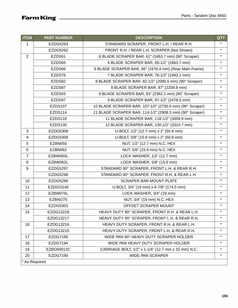
Parts - Tandem Disc 6650
ITEM PART NUMBER DESCRIPTION QTY
1 EZDG5293 STANDARD SCRAPER, FRONT L.H. / REAR R.H. *
EZDG5292 FRONT R.H. / REAR L.H. SCRAPER (Not Shown) *
2 EZDS61 6 BLADE SCRAPER BAR, 61” (1663.7 mm) (90° Scraper) *
EZDS65 6 BLADE SCRAPER BAR, 65-1/2” (1663.7 mm) *
EZDS66 6 BLADE SCRAPER BAR, 66” (1676.4 mm) (Rear Main Frame) *
EZDS76 7 BLADE SCRAPER BAR, 76-1/2” (1943.1 mm) *
EZDS82 8 BLADE SCRAPER BAR, 82-1/2” (2095.5 mm) (90° Scraper) *
EZDS87 8 BLADE SCRAPER BAR, 87” (2209.8 mm) *
EZDS93 9 BLADE SCRAPER BAR, 93” (2362.2 mm) (90° Scraper) *
EZDS97 9 BLADE SCRAPER BAR, 97-1/2” (2476.5 mm) *
EZDS107 10 BLADE SCRAPER BAR, 107-1/2” (2730.5 mm) (90° Scraper) *
EZDS114 11 BLADE SCRAPER BAR, 114-1/2” (2908.3 mm) (90° Scraper) *
EZDS118 11 BLADE SCRAPER BAR, 118-1/2” (3009.9 mm) *
EZDS130 12 BLADE SCRAPER BAR, 130-1/2” (3314.7 mm) *
3 EZDG5308 U-BOLT, 1/2” (12.7 mm) x 2” (50.8 mm) *
4 EZDG5309 U-BOLT, 5/8” (15.9 mm) x 2” (50.8 mm) *
5 EZBN050 NUT, 1/2” (12.7 mm) N.C. HEX *
6 EZBN062 NUT, 5/8” (15.9 mm) N.C. HEX *
7 EZBW050L LOCK WASHER, 1/2” (12.7 mm) *
8 EZBW062L LOCK WASHER, 5/8” (15.9 mm) *
9 EZDG5297 STANDARD 90° SCRAPER, FRONT L.H. & REAR R.H. *
EZDG5298 STANDARD 90° SCRAPER, FRONT R.H. & REAR L.H. *
10 EZDG5296 SCRAPER BAR MOUNT PLATE *
11 EZDGI3145 U-BOLT, 3/4” (19 mm) x 6-7/8” (174.5 mm) *
12 EZBW075L LOCK WASHER, 3/4” (19 mm) *
13 EZBNO75 NUT, 3/4” (19 mm) N.C. HEX *
14 EZDG5303 OFFSET SCRAPER MOUNT *
15 EZDG13218 HEAVY DUTY 90° SCRAPER, FRONT R.H. & REAR L.H. *
EZDG13217 HEAVY DUTY 90° SCRAPER, FRONT L.H. & REAR R.H. *
16 EZDG13216 HEAVY DUTY SCRAPER, FRONT R.H. & REAR L.H. *
EZDG13215 HEAVY DUTY SCRAPER, FRONT L.H. & REAR R.H. *
17 EZDG7195 WIDE PAN 90° HEAVY DUTY SCRAPER HOLDER *
18 EZDG7194 WIDE PAN HEAVY DUTY SCRAPER HOLDER *
19 EZBO50012C CARRIAGE BOLT, 1/2” x 1-1/4” (12.7 mm x 32 mm) N.C. *
20 EZDG7190 WIDE PAN SCRAPER *
* As Required
155
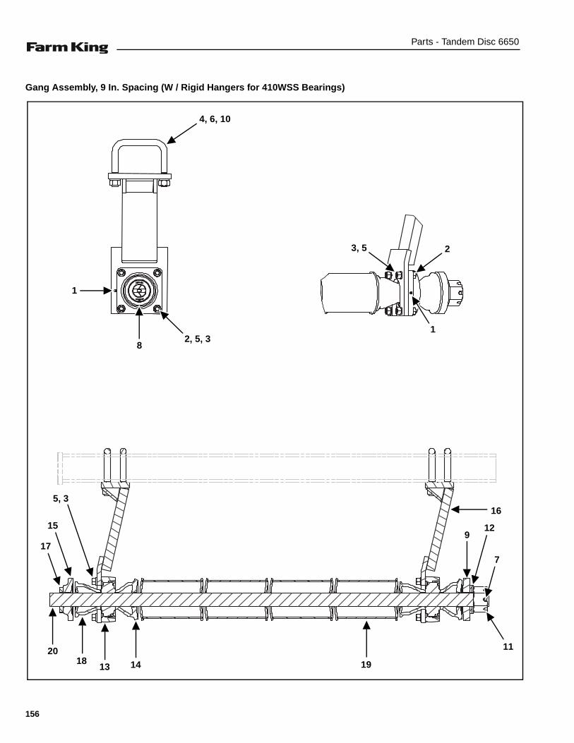
Parts - Tandem Disc 6650
Gang Assembly, 9 In. Spacing (W / Rigid Hangers for 410WSS Bearings)
4, 6, 10
1
82, 5, 3
3, 5 2
1
16
912
7
11
191813 14
20
17
15
5, 3
156
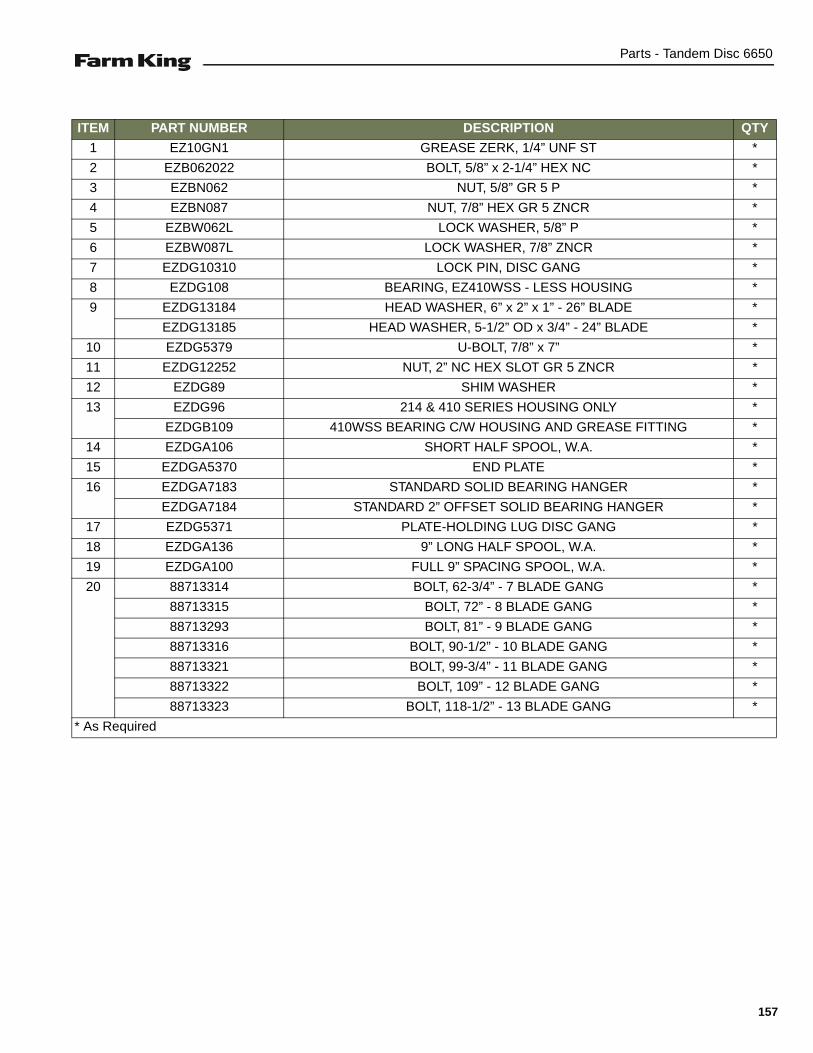
Parts - Tandem Disc 6650
ITEM PART NUMBER DESCRIPTION QTY
1 EZ10GN1 GREASE ZERK, 1/4” UNF ST *
2 EZB062022 BOLT, 5/8” x 2-1/4” HEX NC *
3 EZBN062 NUT, 5/8” GR 5 P *
4 EZBN087 NUT, 7/8” HEX GR 5 ZNCR *
5 EZBW062L LOCK WASHER, 5/8” P *
6 EZBW087L LOCK WASHER, 7/8” ZNCR *
7 EZDG10310 LOCK PIN, DISC GANG *
8 EZDG108 BEARING, EZ410WSS - LESS HOUSING *
9 EZDG13184 HEAD WASHER, 6” x 2” x 1” - 26” BLADE *
EZDG13185 HEAD WASHER, 5-1/2” OD x 3/4” - 24” BLADE *
10 EZDG5379 U-BOLT, 7/8” x 7” *
11 EZDG12252 NUT, 2” NC HEX SLOT GR 5 ZNCR *
12 EZDG89 SHIM WASHER *
13 EZDG96 214 & 410 SERIES HOUSING ONLY *
EZDGB109 410WSS BEARING C/W HOUSING AND GREASE FITTING *
14 EZDGA106 SHORT HALF SPOOL, W.A. *
15 EZDGA5370 END PLATE *
16 EZDGA7183 STANDARD SOLID BEARING HANGER *
EZDGA7184 STANDARD 2” OFFSET SOLID BEARING HANGER *
17 EZDG5371 PLATE-HOLDING LUG DISC GANG *
18 EZDGA136 9” LONG HALF SPOOL, W.A. *
19 EZDGA100 FULL 9” SPACING SPOOL, W.A. *
20 88713314 BOLT, 62-3/4” - 7 BLADE GANG *
88713315 BOLT, 72” - 8 BLADE GANG *
88713293 BOLT, 81” - 9 BLADE GANG *
88713316 BOLT, 90-1/2” - 10 BLADE GANG *
88713321 BOLT, 99-3/4” - 11 BLADE GANG *
88713322 BOLT, 109” - 12 BLADE GANG *
88713323 BOLT, 118-1/2” - 13 BLADE GANG *
* As Required
157
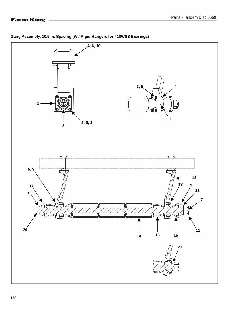
Parts - Tandem Disc 6650
Gang Assembly, 10.5 In. Spacing (W / Rigid Hangers for 410WSS Bearings)
4, 6, 10
1
82, 5, 3
3, 5 2
1
18
912
7
1120
17
5, 3
13
14 16 15
21
19
158
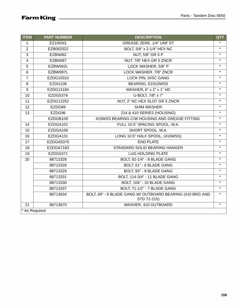
Parts - Tandem Disc 6650
ITEM PART NUMBER DESCRIPTION QTY
1 EZ10GN1 GREASE ZERK, 1/4” UNF ST *
2 EZB062022 BOLT, 5/8” x 2-1/4” HEX NC *
3 EZBN062 NUT, 5/8” GR 5 P *
4 EZBN087 NUT, 7/8” HEX GR 5 ZNCR *
5 EZBW062L LOCK WASHER, 5/8” P *
6 EZBW087L LOCK WASHER, 7/8” ZNCR *
7 EZDG10310 LOCK PIN, DISC GANG *
8 EZDG108 BEARING, EZ410WSS *
9 EZDG13184 WASHER, 6” x 2” x 1” HD *
10 EZDG5379 U-BOLT, 7/8” x 7” *
11 EZDG12252 NUT, 2” NC HEX SLOT GR 5 ZNCR *
12 EZDG89 SHIM WASHER *
13 EZDG96 214 & 410 SERIES (HOUSING) *
EZDGB109 410WSS BEARING C/W HOUSING AND GREASE FITTING. *
14 EZDGA101 FULL 10.5” SPACING SPOOL, W.A. *
15 EZDGA106 SHORT SPOOL, W.A. *
16 EZDGA131 LONG 10.5” HALF SPOOL, (410WSS) *
17 EZDGA5370 END PLATE *
18 EZDGA7183 STANDARD SOLID BEARING HANGER *
19 EZDG5371 LUG HOLDING PLATE *
20 88713328 BOLT, 82-1/4” - 8 BLADE GANG *
88713326 BOLT, 61” - 6 BLADE GANG *
88713329 BOLT, 93” - 9 BLADE GANG *
88713331 BOLT, 114-3/4” - 11 BLADE GANG *
88713330 BOLT, 104” - 10 BLADE GANG *
88713337 BOLT, 71-1/2” - 7 BLADE GANG *
88713634 BOLT, 69” - 6 BLADE GANG W/ OUTBOARD BEARING (410 BRG AND STD T2-215)
*
21 88713670 WASHER, 410 OUTBOARD *
* As Required
159

Parts - Tandem Disc 6650
Gang Assembly, 10.5 In. Spacing (W / Rigid Hangers for T2 - 215 Bearings)
5, 2, 1
17
22
21
14
114
3
6
13
10
15
9
16
19
12
16
78
18, 19, 20
160

Parts - Tandem Disc 6650
ITEM PART NUMBER DESCRIPTION QTY
1 EZBN087 NUT, 7/8” HEX GR5 ZNCR *
2 EZBW087L LOCK WASHER, 7/8” ZNCR *
3 EZDG10310 PIN-LOCK DISC GANG *
4 EZDG13184 WASHER, HD 6 X 2 X 1 *
5 EZDG5379 U-BOLT, 7/8” x 7” *
6 EZDG12252 NUT, 2” NC HEX SLOT GR 5 ZNCR *
7 EZDG89 WASHER-SHIM *
8 EZDGA101 SPOOL-W.A. FULL 10.5IN SPACING *
9 EZDGA5370 PLATE-END DISC GANG *
10 EZDG5371 LUG HOLDING PLATE *
11 EZDGA10563 SHORT HALF SPOOL WASHER *
12 EZDGB9900 BEARING ASSEMBLY, HSG *
13 EZDGA103 HALF SPOOL, 4-1/2” x 4-3/16” W.A *
14 EZDGA13162 STANDARD HANGER BRACKET, W.A. *
EZDGA13163 2” OFFSET HANGER BRACKET, W.A. *
15 88713326 BOLT, 61” (6 BLADE GANG) - WITH OUTBOARD BRG *
88713634 BOLT, 69” (6 BLADE GANG) *
88713327 BOLT, 71-1/2” (7 BLADE GANG) *
88713328 BOLT, 82-1/4” (8 BLADE GANG) *
88713329 BOLT, 93” (9 BLADE GANG) *
88713330 BOLT, 104” (10 BLADE GANG) *
88713331 BOLT, 114-3/4” (11 BLADE GANG) *
88713332 BOLT, 125-3/4” (12 BLADE GANG) *
16 EZDG13185 END PLATE, 215 OUTBOARD - STD 215 BRG *
17 EZB062100 BOLT, 5/8” NC x 10” HEX CAP GR5 ZNCR - LESS WEAR GUARD *
18 EZBN062L LOCK NUT, 5/8” NC NYLON *
19 EZBN062 NUT, 5/8” GR 5 P *
20 EZBW17506812F FLAT WASHER, 11/16” ZNCR *
21 EZDG10590 WEAR GUARD *
22 EZB062110 BOLT, 5/8” NC x 11” HEX CAP GR 5 ZNCR (USED WITH WEAR GUARD) *
* As Required
161

Parts - Tandem Disc 6650
Gang Assembly, 10.5 In. Spacing (W / Rigid Hangers for T2 - 215 Bearings & Interlocking Half Spools)
5, 2, 1
17
22
21
14
114
3
6
13
10
15
9
16
19
12
16
78
18, 19, 20
13
23
162

Parts - Tandem Disc 6650
ITEM PART NUMBER DESCRIPTION QTY
1 EZBN087 NUT, 7/8” HEX GR5 ZNCR *
2 EZBW087L LOCK WASHER, 7/8” ZNCR *
3 EZDG10310 PIN-LOCK DISC GANG *
4 EZDG13184 WASHER, HD 6 X 2 X 1 *
5 EZDG5379 U-BOLT, 7/8” x 7” *
6 EZDG12252 NUT, 2” NC HEX SLOT GR 5 ZNCR *
7 EZDG89 WASHER-SHIM *
8 EZDGA101 SPOOL-W.A. FULL 10.5IN SPACING *
9 EZDGA5370 PLATE-END DISC GANG *
10 EZDG5371 LUG HOLDING PLATE *
11 EZDG9919 SHORT HALF SPOOL - INTERLOCKING *
12 EZDGB9940 BEARING ASSEMBLY, 9” SLEEVE - INTERLOCKING *
13 EZDG9917 LONG HALF SPOOL - INTERLOCKING *
14 EZDGA13162 STANDARD HANGER BRACKET, W.A. *
EZDGA13163 2” OFFSET HANGER BRACKET, W.A. *
15 88713326 BOLT, 61” (6 BLADE GANG) - WITH OUTBOARD BRG *
88713634 BOLT, 69” (6 BLADE GANG) *
88713327 BOLT, 71-1/2” (7 BLADE GANG) *
88713328 BOLT, 82-1/4” (8 BLADE GANG) *
88713329 BOLT, 93” (9 BLADE GANG) *
88713330 BOLT, 104” (10 BLADE GANG) *
88713331 BOLT, 114-3/4” (11 BLADE GANG) *
88713332 BOLT, 125-3/4” (12 BLADE GANG) *
16 88716490 END PLATE, 5-1/2” OD 215 OUTBOARD - INTERLOCKING BRG *
17 EZB062010 BOLT, 5/8” NC x 10” HEX CAP GR5 ZNCR - LESS WEAR GUARD *
18 EZBN062L LOCK NUT, 5/8” NC NYLON *
19 EZBN062 NUT, 5/8” GR 5 P *
20 EZBW17506812F FLAT WASHER, 11/16” ZNCR *
21 EZDG10590 WEAR GUARD *
22 EZB062110 BOLT, 5/8” NC x 11” HEX CAP GR 5 ZNCR (USED WITH WEAR GUARD) *
23 EZDG9937 BEARING ASSEMBLY, OUTBOARD, 7-3/16” SLEEVE - INTERLOCKING *
* As Required
163
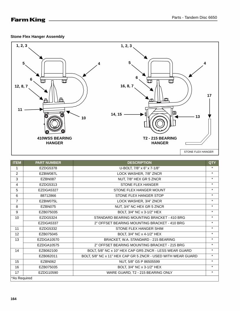
Parts - Tandem Disc 6650
Stone Flex Hanger Assembly
ITEM PART NUMBER DESCRIPTION QTY
1 EZDG5378 U-BOLT, 7/8” x 6” x 7-1/8” *
2 EZBW087L LOCK WASHER, 7/8” ZNCR *
3 EZBN087 NUT, 7/8” HEX GR 5 ZNCR *
4 EZDG5313 STONE FLEX HANGER *
5 EZDGA5327 STONE FLEX HANGER MOUNT *
6 88712866 STONE FLEX HANGER STOP *
7 EZBW075L LOCK WASHER, 3/4” ZNCR *
8 EZBN075 NUT, 3/4” NC HEX GR 5 ZNCR *
9 EZB075035 BOLT, 3/4” NC x 3-1/2” HEX *
10 EZDG5324 STANDARD BEARING MOUNTING BRACKET - 410 BRG *
EZDGA5337 2” OFFSET BEARING MOUNTING BRACKET - 410 BRG *
11 EZDG5332 STONE FLEX HANGER SHIM *
12 EZB075045 BOLT, 3/4” NC x 4-1/2” HEX *
13 EZDGA10570 BRACKET, W.A. STANDARD - 215 BEARING *
EZDGA10575 2” OFFSET BEARING MOUNTING BRACKET - 215 BRG *
14 EZB062100 BOLT, 5/8” NC x 10” HEX CAP GR5 ZNCR - LESS WEAR GUARD *
EZB062011 BOLT, 5/8” NC x 11” HEX CAP GR 5 ZNCR - USED WITH WEAR GUARD *
15 EZBN062 NUT, 5/8” G5 P 86505599 *
16 EZB075035 BOLT, 3/4” NC x 3-1/2” HEX *
17 EZDG10590 WARE GUARD, T2 - 215 BEARING ONLY *
*As Required
STONE FLEX HANGER
1, 2, 3
410WSS BEARING HANGER
T2 - 215 BEARING HANGER
6
12, 8, 7
1114, 15
6
5 4 4
13
5
1, 2, 3
10
17
16, 8, 7
164
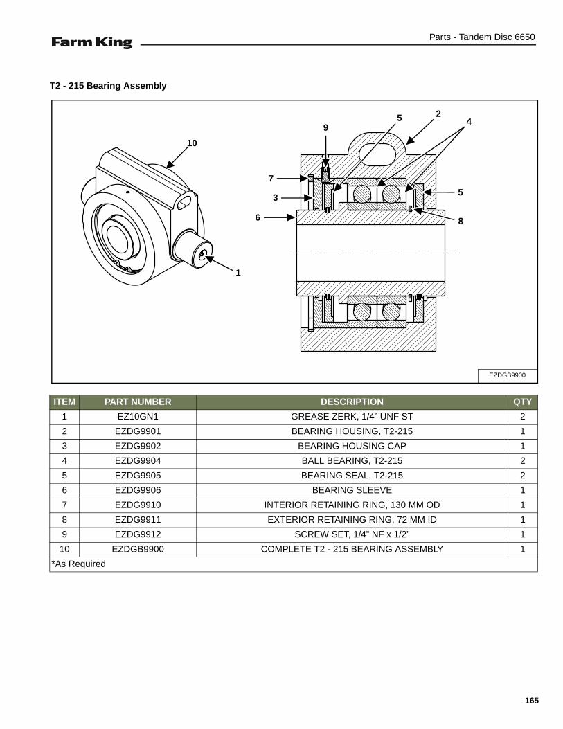
Parts - Tandem Disc 6650
T2 - 215 Bearing Assembly
ITEM PART NUMBER DESCRIPTION QTY
1 EZ10GN1 GREASE ZERK, 1/4” UNF ST 2
2 EZDG9901 BEARING HOUSING, T2-215 1
3 EZDG9902 BEARING HOUSING CAP 1
4 EZDG9904 BALL BEARING, T2-215 2
5 EZDG9905 BEARING SEAL, T2-215 2
6 EZDG9906 BEARING SLEEVE 1
7 EZDG9910 INTERIOR RETAINING RING, 130 MM OD 1
8 EZDG9911 EXTERIOR RETAINING RING, 72 MM ID 1
9 EZDG9912 SCREW SET, 1/4” NF x 1/2” 1
10 EZDGB9900 COMPLETE T2 - 215 BEARING ASSEMBLY 1
*As Required
EZDGB9900
1
6
3
7
95 4
2
5
8
10
165

Parts - Tandem Disc 6650
T2-215 Bearing Assembly, 7-3/16 In. Sleeve
ITEM PART NUMBER DESCRIPTION QTY
1 EZ10GN1 GREASE ZERK, 1/4” UNF ST 2
2 EZDG9901 BEARING HOUSING, T2-215 1
3 EZDG9902 BEARING HOUSING CAP 1
4 EZDG9904 BALL BEARING, T2-215 2
5 EZDG9905 BEARING SEAL, T2-215 2
6 EZDG9924 BEARING SLEEVE - 7-3/16” LONG 1
7 EZDG9910 INTERIOR RETAINING RING, 130 MM OD 1
8 EZDG9911 EXTERIOR RETAINING RING, 72 MM ID 1
9 EZDG9912 SCREW SET, 1/4” NF x 1/2” 1
10 EZDGB9937 COMPLETE T2-215 BEARING ASSEMBLY - 7-3/16” SLEEVE 1
*As Required
EZDGB9937
1
105
4
9
2
7
3
6
8
166
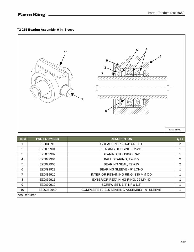
Parts - Tandem Disc 6650
T2-215 Bearing Assembly, 9 In. Sleeve
ITEM PART NUMBER DESCRIPTION QTY
1 EZ10GN1 GREASE ZERK, 1/4” UNF ST 2
2 EZDG9901 BEARING HOUSING, T2-215 1
3 EZDG9902 BEARING HOUSING CAP 1
4 EZDG9904 BALL BEARING, T2-215 2
5 EZDG9905 BEARING SEAL, T2-215 2
6 EZDG9922 BEARING SLEEVE - 9” LONG 1
7 EZDG9910 INTERIOR RETAINING RING, 130 MM OD 1
8 EZDG9911 EXTERIOR RETAINING RING, 72 MM ID 1
9 EZDG9912 SCREW SET, 1/4” NF x 1/2” 1
10 EZDGB9940 COMPLETE T2-215 BEARING ASSEMBLY - 9” SLEEVE 1
*As Required
EZDGB9940
1
10
7
3
9
5 4
6
8
167

Parts - Tandem Disc 6650
Warning Light Assembly
ITEM PART NUMBER DESCRIPTION QTY
1 EZLK6252 BRACKET-W.A. LIGHT KIT 2
2 EZLK6425 RED LAMP, W/3 PIN PLUG 2
3 EZLK6426 AMBER LAMP, W/2 PIN PLUG 2
4 EZLK6404 PLATE, BACKING, LIGHT KIT 2
5 EZB050085 BOLT, 1/2” NC x 8-1/2” HEX 4
6 EZBN050 NUT, 1/2” NC HEX ZNCR 4
7 EZBW050L LOCK WASHER, 1/2” x 7/8” x 1/8” ZNCR 4
NS EZLK6427 HARNESS, WARNING LIGHTS 55 FT. (Not Shown) 1
88700074
31
2
31
5, 6, 7
4 4
7, 6, 5
2
168
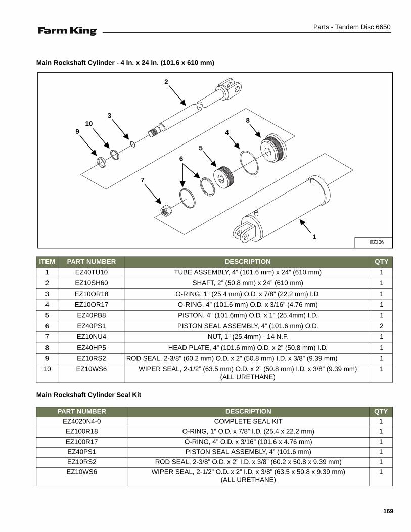
Parts - Tandem Disc 6650
Main Rockshaft Cylinder - 4 In. x 24 In. (101.6 x 610 mm)
Main Rockshaft Cylinder Seal Kit
ITEM PART NUMBER DESCRIPTION QTY
1 EZ40TU10 TUBE ASSEMBLY, 4” (101.6 mm) x 24” (610 mm) 1
2 EZ10SH60 SHAFT, 2” (50.8 mm) x 24” (610 mm) 1
3 EZ10OR18 O-RING, 1” (25.4 mm) O.D. x 7/8” (22.2 mm) I.D. 1
4 EZ10OR17 O-RING, 4” (101.6 mm) O.D. x 3/16” (4.76 mm) 1
5 EZ40PB8 PISTON, 4" (101.6mm) O.D. x 1" (25.4mm) I.D. 1
6 EZ40PS1 PISTON SEAL ASSEMBLY, 4” (101.6 mm) O.D. 2
7 EZ10NU4 NUT, 1” (25.4mm) - 14 N.F. 1
8 EZ40HP5 HEAD PLATE, 4” (101.6 mm) O.D. x 2” (50.8 mm) I.D. 1
9 EZ10RS2 ROD SEAL, 2-3/8” (60.2 mm) O.D. x 2” (50.8 mm) I.D. x 3/8” (9.39 mm) 1
10 EZ10WS6 WIPER SEAL, 2-1/2” (63.5 mm) O.D. x 2” (50.8 mm) I.D. x 3/8” (9.39 mm)(ALL URETHANE)
1
PART NUMBER DESCRIPTION QTY
EZ4020N4-0 COMPLETE SEAL KIT 1
EZ100R18 O-RING, 1” O.D. x 7/8” I.D. (25.4 x 22.2 mm) 1
EZ100R17 O-RING, 4” O.D. x 3/16” (101.6 x 4.76 mm) 1
EZ40PS1 PISTON SEAL ASSEMBLY, 4” (101.6 mm) 1
EZ10RS2 ROD SEAL, 2-3/8” O.D. x 2” I.D. x 3/8” (60.2 x 50.8 x 9.39 mm) 1
EZ10WS6 WIPER SEAL, 2-1/2” O.D. x 2” I.D. x 3/8” (63.5 x 50.8 x 9.39 mm)(ALL URETHANE)
1
EZ3061
7
6
5
4
8
2
310
9
169

Parts - Tandem Disc 6650
LH Wing Rockshaft Cylinder - 3-1/2 In. x 24 In. (88.9 x 610 mm)
LH Rockshaft Cylinder Seal Kit
ITEM PART NUMBER DESCRIPTION QTY
1 EZ35TU15 TUBE ASSEMBLY, 3-1/2” (88.9 mm) x 24” (610 mm) 1
2 EZ10SH59 SHAFT, 1-3/4” (44.4 mm) x 24” (610 mm) 1
3 EZ10OR18 O-RING, 1” (25.4 mm) O.D. x 7/8” (22.2 mm) I.D. 1
4 EZ10OR8 O-RING, 3-1/2” (88.9 mm) O.D. x 3/16” (4.76 mm) 1
5 EZ35PB8 PISTON - 3-1/2” (88.9 mm) O.D. x 1” (25.4 mm) I.D. 1
6 EZ35PS1 PISTON SEAL ASSEMBLY 2
7 EZ10NU4 NUT, 1” (25.4 mm) - 14 N.F. HEX 1
8 EZ35HP9 HEAD PLATE - 3-1/2” (88.9 mm) O.D. x 1-3/4” (44.4 mm) I.D. 1
9 EZ10RS3 ROD SEAL - 1-3/4” (44.4 mm) I.D. x 2-1/8” (54 mm) O.D. x 3/8” (9.39 mm) 1
10 EZ10WS10 WIPER SEAL, 1-3/4” (44.4 mm) O.D. x 2-1/8” (54 mm) I.D. x 1/4” (6.35 mm)(ALL URETHANE)
1
PART NUMBER DESCRIPTION QTY
EZ3517N4-0 COMPLETE SEAL KIT 1
EZ100R18 O-RING, 1” O.D. x 7/8” I.D. (25.4 x 22.2 mm) 1
EZ100R8 O-RING, 3-1/2” O.D. x 3/16” (88.9 x 4.76 mm) 1
EZ35PS1 PISTON SEAL ASSEMBLY, 3-1/2” (88.9 mm) 1
EZ10RS3 ROD SEAL, 1-3/4” I.D. x 2-1/8” O.D. x 3/8” (44.4 x 54 x 9.39 mm) 1
EZ10WS10 WIPER SEAL, 1-3/4” I.D. x 2-1/8” O.D. x 1/4” (44.4 x 54 x 6.35 mm)(ALL URETHANE)
1
EZ3051
7
6
5
4
8
2
310
9
170

Parts - Tandem Disc 6650
RH Wing Rockshaft Cylinder - 3 In. x 24 In. (76.2 x 610 mm)
RH Rockshaft Cylinder Seal Kit
ITEM PART NUMBER DESCRIPTION QTY
1 EZ35TU34 TUBE ASSEMBLY, 3” (76.2 mm) x 24” (610 mm) 1
2 EZ10SH59 SHAFT, 1-3/4” (44.4 mm) x 24” (610 mm) 1
3 EZ10OR18 O-RING, 1” (25.4 mm) O.D. x 7/8” (22.2 mm) I.D. 1
4 EZ10OR3 O-RING, 3” (76.2 mm) O.D. x 3/16” (4.76 mm) 1
5 EZ30PB4 PISTON - 3” (76.2 mm) O.D. x 1” (25.4 mm) I.D. 1
6 EZ30PS1 PISTON SEAL ASSEMBLY 2
7 EZ10NU4 NUT, 1” (25.4 mm) - 14 N.F. HEX 1
8 EZ30HP9 HEAD PLATE - 3” (76.2 mm) O.D. x 1-3/4” (44.4 mm) I.D. 1
9 EZ10RS3 ROD SEAL - 1-3/4” (44.4 mm) I.D. x 2-1/8” (54 mm) O.D. x 3/8” (9.39 mm) 1
10 EZ10WS10 WIPER SEAL, 1-3/4” (44.4 mm) O.D. x 2-1/8” (54 mm) I.D. x 1/4” (6.35 mm)(ALL URETHANE)
1
PART NUMBER DESCRIPTION QTY
EZ3017N4-0 COMPLETE SEAL KIT 1
EZ100R18 O-RING, 1” O.D. x 7/8” I.D. (25.4 x 22.2 mm) 1
EZ100R8 O-RING, 3-1/2” O.D. x 3/16” (88.9 x 4.76 mm) 1
EZ35PS1 PISTON SEAL ASSEMBLY, 3-1/2” (88.9 mm) 1
EZ10RS3 ROD SEAL, 1-3/4” I.D. x 2-1/8” O.D. x 3/8” (44.4 x 54 x 9.39 mm) 1
EZ10WS10 WIPER SEAL, 1-3/4” I.D. x 2-1/8” O.D. x 1/4” (44.4 x 54 x 6.35 mm)(ALL URETHANE)
1
EZ3041
7
6
5
4
8
2
310
9
171

Parts - Tandem Disc 6650
Wing Lift Cylinder - 4 In. x 36 In. (102 x 914 mm)
Wing Lift Cylinder Seal Kit - 4 In. x 36 In. (102 x 914 mm)
ITEM PART NUMBER DESCRIPTION QTY
1 EZ40TU8 TUBE ASSEMBLY 4” x 36” (102 x 914 mm) 1
2 EZ10SH36 SHAFT 1-3/4” x 36” (44.4 x 914 mm) 1
3 EZ10OR19 O-RING, 1-1/8” I.D. x 1-1/4” O.D. (28.5 x 31.8 mm) 1
4 EZ40CU3 U-CUP, 4” (101.6 mm) 2
5 EZ40PB7 PISTON, 4” O.D. x 1-1/4” I.D. (101.6 x 31.7 mm) 1
6 EZ10NU3 LOCK NUT, 1-1/4” (31.8 mm) U.N.F. HEX 1
7 EZ10OR17 O-RING, 3-5/8” I.D. x 4” O.D. (92.1 x 101.6 mm) 1
8 EZ40HP4 HEAD PLATE, 4” O.D. x 1-3/4” I.D. (101.6 x 44.4 mm) 1
9 EZ10RS3 ROS SEAL, 1-3/4” I.D. x 2-1/8” O.D. x 3/8” (44.4 x 54 x 9.39 mm) 1
10 EZ10WS3 WIPER SEAL, 1-3/4” I.D. x 2-1/8” O.D. x 3/16” (44.4 x 54 x 4.76 mm) 1
PART NUMBER DESCRIPTION QTY
EZ4017N4 COMPLETE SEAL KIT 1
EZ40CU3 U-CUP, 4” (101.6 mm) U-Cup 2
EZ100R17 O-RING, 3-5/8” I.D. x 4” O.D. (92.1 x 101.6 mm) 1
EZ100R19 O-RING, 1-1/8” I.D. x 1-1/4” O.D. (28.4 x 31.7 mm) 1
EZ100RS3 ROD SEAL, 1-3/4” I.D x 2-1/8” O.D. x 3/8” (44.4 x 54 x 9.39 mm) 1
EZ10WS3 WIPER SEAL, 1-3/4” I.D. x 2-1/8” O.D. x 3/16” (44.4 x 54 x 4.76 mm) 1
EZ100R13 O-RING, 1” O.D. x 1-1/4” O.D. (25.4 x 31.8 mm) 1
EZ248
1
2
8
9
310
74
5
46
172
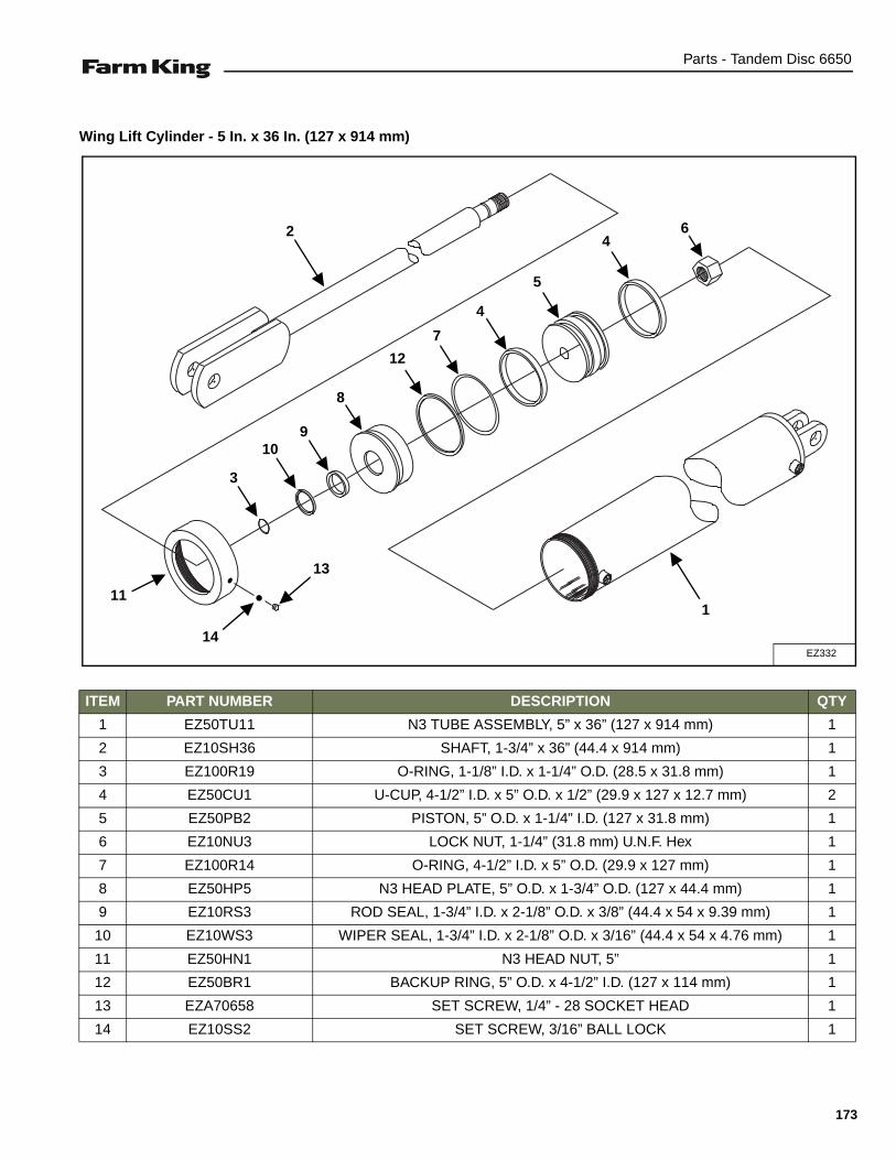
Parts - Tandem Disc 6650
Wing Lift Cylinder - 5 In. x 36 In. (127 x 914 mm)
ITEM PART NUMBER DESCRIPTION QTY
1 EZ50TU11 N3 TUBE ASSEMBLY, 5” x 36” (127 x 914 mm) 1
2 EZ10SH36 SHAFT, 1-3/4” x 36” (44.4 x 914 mm) 1
3 EZ100R19 O-RING, 1-1/8” I.D. x 1-1/4” O.D. (28.5 x 31.8 mm) 1
4 EZ50CU1 U-CUP, 4-1/2” I.D. x 5” O.D. x 1/2” (29.9 x 127 x 12.7 mm) 2
5 EZ50PB2 PISTON, 5” O.D. x 1-1/4” I.D. (127 x 31.8 mm) 1
6 EZ10NU3 LOCK NUT, 1-1/4” (31.8 mm) U.N.F. Hex 1
7 EZ100R14 O-RING, 4-1/2” I.D. x 5” O.D. (29.9 x 127 mm) 1
8 EZ50HP5 N3 HEAD PLATE, 5” O.D. x 1-3/4” O.D. (127 x 44.4 mm) 1
9 EZ10RS3 ROD SEAL, 1-3/4” I.D. x 2-1/8” O.D. x 3/8” (44.4 x 54 x 9.39 mm) 1
10 EZ10WS3 WIPER SEAL, 1-3/4” I.D. x 2-1/8” O.D. x 3/16” (44.4 x 54 x 4.76 mm) 1
11 EZ50HN1 N3 HEAD NUT, 5” 1
12 EZ50BR1 BACKUP RING, 5” O.D. x 4-1/2” I.D. (127 x 114 mm) 1
13 EZA70658 SET SCREW, 1/4” - 28 SOCKET HEAD 1
14 EZ10SS2 SET SCREW, 3/16” BALL LOCK 1
EZ332
1
2
8
9
3
10
7
4
5
46
11
12
14
13
173
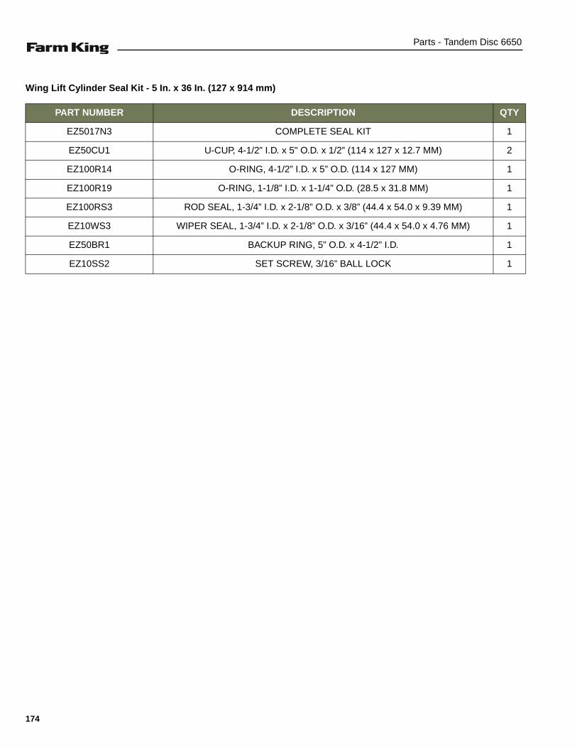
Parts - Tandem Disc 6650
Wing Lift Cylinder Seal Kit - 5 In. x 36 In. (127 x 914 mm)
PART NUMBER DESCRIPTION QTY
EZ5017N3 COMPLETE SEAL KIT 1
EZ50CU1 U-CUP, 4-1/2” I.D. x 5" O.D. x 1/2” (114 x 127 x 12.7 MM) 2
EZ100R14 O-RING, 4-1/2” I.D. x 5” O.D. (114 x 127 MM) 1
EZ100R19 O-RING, 1-1/8” I.D. x 1-1/4” O.D. (28.5 x 31.8 MM) 1
EZ100RS3 ROD SEAL, 1-3/4” I.D. x 2-1/8” O.D. x 3/8” (44.4 x 54.0 x 9.39 MM) 1
EZ10WS3 WIPER SEAL, 1-3/4” I.D. x 2-1/8” O.D. x 3/16” (44.4 x 54.0 x 4.76 MM) 1
EZ50BR1 BACKUP RING, 5” O.D. x 4-1/2” I.D. 1
EZ10SS2 SET SCREW, 3/16” BALL LOCK 1
174

Specifications - Tandem Disc 6650
SPECIFICATIONS
SPECIFICATIONS . . . . . . . . . . . . . . . . . . . . . . . . . . . . . . . . . . . . . . . . . . . . . . . . . . . . . . . . . . . . . 177Dimensions . . . . . . . . . . . . . . . . . . . . . . . . . . . . . . . . . . . . . . . . . . . . . . . . . . . . . . . . . . . . . . . . 177Performance . . . . . . . . . . . . . . . . . . . . . . . . . . . . . . . . . . . . . . . . . . . . . . . . . . . . . . . . . . . . . . . 177Hydraulic Cylinders . . . . . . . . . . . . . . . . . . . . . . . . . . . . . . . . . . . . . . . . . . . . . . . . . . . . . . . . . . 178Bolt Torques . . . . . . . . . . . . . . . . . . . . . . . . . . . . . . . . . . . . . . . . . . . . . . . . . . . . . . . . . . . . . . . 178
HYDRAULIC SCHEMATIC (NARROW WING) . . . . . . . . . . . . . . . . . . . . . . . . . . . . . . . . . . . . . . . . 179
HYDRAULIC SCHEMATIC (WIDE WING) . . . . . . . . . . . . . . . . . . . . . . . . . . . . . . . . . . . . . . . . . . . 180
HARDWARE TORQUE VALUES . . . . . . . . . . . . . . . . . . . . . . . . . . . . . . . . . . . . . . . . . . . . . . . . . . 181Metric Chart . . . . . . . . . . . . . . . . . . . . . . . . . . . . . . . . . . . . . . . . . . . . . . . . . . . . . . . . . . . . . . . 181Imperial Chart . . . . . . . . . . . . . . . . . . . . . . . . . . . . . . . . . . . . . . . . . . . . . . . . . . . . . . . . . . . . . . 182
HYDRAULIC CONNECTION SPECIFICATIONS . . . . . . . . . . . . . . . . . . . . . . . . . . . . . . . . . . . . . .183O-Ring Fitting (Straight Thread) . . . . . . . . . . . . . . . . . . . . . . . . . . . . . . . . . . . . . . . . . . . . . . . .183O-ring Face Seal Connection . . . . . . . . . . . . . . . . . . . . . . . . . . . . . . . . . . . . . . . . . . . . . . . . . . 183Flare Fitting . . . . . . . . . . . . . . . . . . . . . . . . . . . . . . . . . . . . . . . . . . . . . . . . . . . . . . . . . . . . . . . . 183Port Seal (O-ring Boss) Fitting . . . . . . . . . . . . . . . . . . . . . . . . . . . . . . . . . . . . . . . . . . . . . . . . . 183Tubelines And Hoses . . . . . . . . . . . . . . . . . . . . . . . . . . . . . . . . . . . . . . . . . . . . . . . . . . . . . . . . 183
175

Specifications - Tandem Disc 6650
176
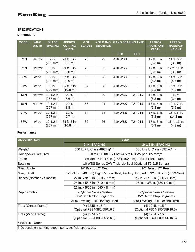
Specifications - Tandem Disc 6650
SPECIFICATIONS
Dimensions
Performance
MODEL WING WIDTH
BLADE SPACING
APPROX. CUTTING
WIDTH
# OF BLADES
# OF GANG BEARINGS
GANG BEARING TYPE APPROX. TRANSPORT
WIDTH
APPROX. TRANSPORT
HEIGHT
STD OPT
70N Narrow 9 in.(230 mm)
26 ft. 6 in.(8.1 m)
70 22 410 WSS - 17 ft. 6 in.(5.3 m)
11 ft. 6 in.(3.5 m)
78N Narrow 9 in.(230 mm)
29 ft. 6 in.(9.0 m)
78 22 410 WSS - 17 ft. 6 in.(5.3 m)
12 ft. 11 in.(3.9 m)
86W Wide 9 in.(230 mm)
32 ft. 6 in.(9.9 m)
86 26 410 WSS - 17 ft. 6 in.(5.3 m)
14 ft. 5 in.(4.4 m)
94W Wide 9 in.(230 mm)
35 ft. 6 in.(10.8 m)
94 28 410 WSS - 17 ft. 6 in.(5.3 m)
15 ft. 9 in.(4.8 m)
58N Narrow 10-1/2 in.(267 mm)
25 ft.(7.6 m)
58 20 410 WSS T2 - 215 17 ft. 6 in.(5.3 m)
11 ft.(3.4 m)
66N Narrow 10-1/2 in.(267 mm)
29 ft.(8.8 m)
66 24 410 WSS T2 - 215 17 ft. 6 in.(5.3 m)
12 ft. 7 in.(3.7 m)
74W Wide 10-1/2 in.(267 mm)
32 ft.(9.7 m)
74 24 410 WSS T2 - 215 17 ft. 6 in.(5.3 m)
13 ft. 5 in.(14.1 m)
83W Wide 10-1/2 in.(267 mm)
35 ft. 6 in.(10.8 m)
82 26 410 WSS T2 - 215 17 ft. 6 in.(5.3 m)
15 ft. 11 in.(4.9 m)
DESCRIPTION 6650
9 IN. SPACING 10-1/2 IN. SPACING
Weight* 600 lb. / ft. Class (892 kg/m) 600 lb. / ft. Class (892 kg/m)
Horsepower Required 6.0 to 8.0 DBHP / Foot (4.5 to 6.0 kW per 305 mm)†
Frame Welded, 6 in. x 4 in. (152 x 102 mm) Tubular Steel Frame
Bearings 410 WSS Series C/W Triple Lip Seal (Optional T2-215 Series)
Gang Angle 20° Front / 17° Rear 20° Front / 17° Rear
Gang Shaft 1-15/16 in. (49 mm) High Carbon Steel, Factory Torqued to 3200 ft. - lb. (4339 N•m)
Blades (Notched / Smooth) 22 in. x 9/32 in. (610 x 7 mm) 26 in. x 5/16 in. (660 x 8 mm)
24 in. x 5/16 in. (610 x 8 mm) 26 in. x 3/8 in. (660 x 9 mm)
26 in. x 5/16 in. (660 x 8 mm) -
Depth Control 3-Cylinder Series SystemC/W Depth Stop Segments
3-Cylinder Series SystemC/W Depth Stop Segments
Auto-Leveling, Full Floating Hitch Auto-Leveling, Full Floating Hitch
Tires (Center Frame) (4) 12.5L x 15 FI(Optional FS24-380/55R16.5)
(4) 12.5L x 15 FI(Optional FS24-380/55R16.5)
Tires (Wing Frame) (4) 12.5L x 15 FI(Optional FS24-380/55R16.5)
(4) 12.5L x 15 FI(Optional FS24-380/55R16.5)
* W/24 in. Blades
† Depends on working depth, soil type, field speed, etc.
177

Specifications - Tandem Disc 6650
Hydraulic Cylinders
Bolt Torques
APPLICATION SIZE # REQUIRED
Center Frame Lift 4 in. x 24 in. Rephasing 1
L.H. Wing Frame Lift 3-1/2 in. x 24 in. Rephasing 1
R.H. Wing Frame Lift 3 in. x 24 in. Rephasing 1
Wing Lift (25 ft. to 29 ft.) 4 in. x 36 in. 2
Wing Lift (32 ft. to 35 ft. 6 in.) 5 in. x 36 in. 2
DESCRIPTION TORQUE
Gang Bolts (1-15/16 in. (49 mm) diameter) 3200 ft. - lb. (4339 N•m)
Gang Beam Bolts (1-1/4 in. (31 mm) diameter) 840 ft. - lb. (1139.2 N•m)
Leveling Crank Bolts (1-1/4 in. (31 mm) diameter) 840 ft. - lb. (1139.2 N•m)
Wheel Bolts (9/16 in. (14 mm) diameter) 130 ft. - lb. (176.3 N•m)
Bearing Hanger U-bolts - 7/8 in. (15 mm) diameter) 430 ft. - lb. (583 N•m) (Solid Hangers)
178
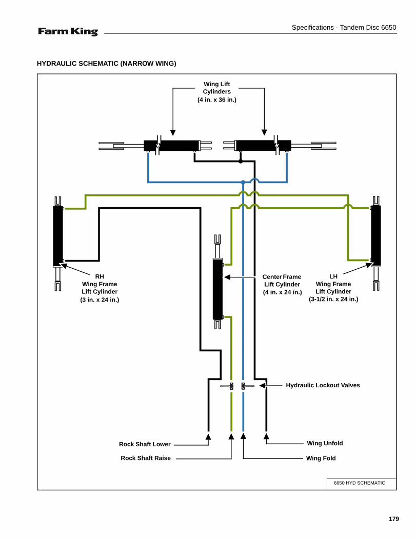
Specifications - Tandem Disc 6650
HYDRAULIC SCHEMATIC (NARROW WING)
6650 HYD SCHEMATIC
Center Frame Lift Cylinder
RHWing Frame Lift Cylinder
LHWing Frame Lift Cylinder
(3 in. x 24 in.) (3-1/2 in. x 24 in.)
Wing Lift Cylinders
(4 in. x 36 in.)
(4 in. x 24 in.)
Hydraulic Lockout Valves
Rock Shaft Raise Wing Fold
Wing UnfoldRock Shaft Lower
179

Specifications - Tandem Disc 6650
HYDRAULIC SCHEMATIC (WIDE WING)
6650 HYD SCHEMATIC
Center Frame Lift Cylinder
RHWing Frame Lift Cylinder
LHWing Frame Lift Cylinder
(3 in. x 24 in.) (3-1/2 in. x 24 in.)
Wing Lift Cylinders
(5 in. x 36 in.)
(4 in. x 24 in.)
Hydraulic Lockout Valves
Rock Shaft Raise Wing Fold
Wing UnfoldRock Shaft Lower
180

Specifications - Tandem Disc 6650
HARDWARE TORQUE VALUES
Metric Chart
NOTE: Do not use the values listed in the charts if a different torque value or tightening procedure is specifiedin this manual for a specific application. Torque values listed are for general use only.
Use the following charts to determine the correct torque when checking, adjusting or replacing hardware. Torquevalues are listed in newton-meters (inch* or foot pounds) for normal assembly applications.
Nominal Size
Class 5.8 Class 8.8 Class 10.9 Lock nuts
Unplated PlatedW / ZnCr
Unplated PlatedW / ZnCr
Unplated PlatedW / ZnCr
CL.8 w/CL. 8.8 Bolt
M4 1.7 (15*) 2.2 (19*) 2.6 (23*) 3.4 (30*) 3.7 (33*) 4.8 (42*) 1.8 (16*)
M6 5.8 (51*) 7.6 (67*) 8.9 (79*) 12 (102*) 13 (115*) 17 (150*) 6.3 (56*)
M8 14 (124*) 18 (159*) 22 (195*) 28 (248*) 31 (274*) 40 (354*) 15 (133*)
M10 28 (21) 36 (27) 43 (32) 56 (41) 61 (45) 79 (58) 30 (22)
M12 49 (36) 63 (46) 75 (55) 97 (72) 107 (79) 138 (102) 53 (39)
M16 121 (89) 158 (117) 186 (137) 240 (177) 266 (196) 344 (254) 131 (97)
M20 237 (175) 307 (226) 375 (277) 485 (358) 519 (383) 671 (495) 265 (195)
M24 411 (303) 531 (392) 648 (478) 839 (619) 897 (662) 1160 (855) 458 (338)
NOTE: Torque values shown with * are inch pounds.
Identification of Hex Cap Screws and Carriage Bolts - Classes 5 and up
XYZ
8 8
8 8ABCD
MANUFACTURER’S IDENTIFICATION
PROPERTY CLASS
Identification of Hex Nuts and Lock Nuts - Classes 5 and up
PROPERTY CLASS
MANUFACTURER’S IDENTIFICATION
PROPERTY CLASS
AB
AB8
8 AB
181
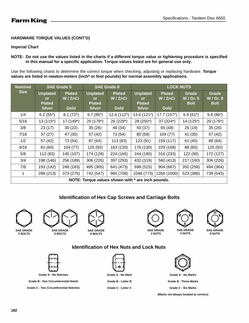
Specifications - Tandem Disc 6650
HARDWARE TORQUE VALUES (CONT’D)
Imperial Chart
NOTE: Do not use the values listed in the charts if a different torque value or tightening procedure is specifiedin this manual for a specific application. Torque values listed are for general use only.
Use the following charts to determine the correct torque when checking, adjusting or replacing hardware. Torquevalues are listed in newton-meters (inch* or foot pounds) for normal assembly applications.
Nominal Size
SAE Grade 5 SAE Grade 8 LOCK NUTS
Unplatedor
Plated Silver
PlatedW / ZnCr
Gold
Unplatedor
Plated Silver
PlatedW / ZnCr
Gold
Unplatedor
Plated Silver
PlatedW / ZnCr
Gold
GradeW / Gr. 5
Bolt
GradeW / Gr. 8
Bolt
1/4 6.2 (55*) 8.1 (72*) 9.7 (86*) 12.6 (112*) 13.6 (121*) 17.7 (157*) 6.9 (61*) 9.8 (86*)
5/16 13 (115*) 17 (149*) 20 (178*) 26 (229*) 28 (250*) 37 (324*) 14 (125*) 20 (176*)
3/8 23 (17) 30 (22) 35 (26) 46 (34) 50 (37) 65 (48) 26 (19) 35 (26)
7/16 37 (27) 47 (35) 57 (42) 73 (54) 80 (59) 104 (77) 41 (30) 57 (42)
1/2 57 (42) 73 (54) 87 (64) 113 (83) 123 (91) 159 (117) 61 (45) 88 (64)
9/16 81 (60) 104 (77) 125 (92) 163 (120) 176 (130) 229 (169) 88 (65) 125 (92)
5/8 112 (83) 145 (107) 174 (128) 224 (165) 244 (180) 316 (233) 122 (90) 172 (127)
3/4 198 (146) 256 (189) 306 (226) 397 (293) 432 (319) 560 (413) 217 (160) 306 (226)
7/8 193 (142) 248 (183) 495 (365) 641 (473) 698 (515) 904 (667) 350 (258) 494 (364)
1 289 (213) 373 (275) 742 (547) 960 (708) 1048 (773) 1356 (1000) 523 (386) 739 (545)
NOTE: Torque values shown with * are inch pounds.
Identification of Hex Cap Screws and Carriage Bolts
Identification of Hex Nuts and Lock Nuts
SAE GRADE 2 BOLTS
SAE GRADE 5 BOLTS
SAE GRADE 8 BOLTS
SAE GRADE 2 NUTS
SAE GRADE 5 NUTS
SAE GRADE 8 NUTS
B
Grade A - No Notches
Grade B - One Circumferential Notch
Grade C - Two Circumferential Notches
Grade A - No Mark
Grade B - Letter B
Grade C - Letter C
Grade A - No Marks
Grade B - Three Marks
Grade C - Six Marks
(Marks not always located at corners)
182

Specifications - Tandem Disc 6650
HYDRAULIC CONNECTION SPECIFICATIONS
O-Ring Fitting (Straight Thread)
Lubricate the O-ring before installing the fitting. Loosenthe jam nut and install the fitting. Tighten the jam nut untilthe washer is tight against the surface.
O-ring Face Seal Connection
Figure 166
When the fitting is tightened, you can feel when the fittingis tight to eliminate leakage caused by under or overtorqued fittings. Use petroleum jelly to hold the O-ring inposition until the fittings are assembled.
Flare Fitting
Figure 167
Tighten until the nut makes contact with the seat. Use thechart [Figure 167] to find the correct tightness needed.
NOTE: If the fitting leaks, disconnect and inspect theseat area for damage.
Port Seal (O-ring Boss) Fitting
Figure 168
NOTE: Port seal and nut, washer and O-ring (O-ringBoss) fittings use the same tightening torquevalve chart.
If a torque wrench cannot be used, use the followingmethod.
Tighten the nut until it just makes metal to metal contact,you can feel the resistance.
Tighten the nut with a wrench no more than one hex flatmaximum.
Do not over tighten the port seal fitting.
NOTE: If a torque wrench cannot be used, use thehex flat tightening method as an approximateguideline.
NOTE: Port seal fittings are not recommended in allapplications. Use O-ring boss fittings in theseapplications.
Tubelines And Hoses
Replace any tubelines that are bent or flattened. They willrestrict flow, which will slow hydraulic action and causeheat.
Replace hoses which show signs of wear, damage orweather cracked rubber.
Always use two wrenches when loosening and tighteninghose or tubeline fittings.
O-ring Face Seal Tightening TorqueTubeline O.D. Thread Size N•m (ft-lb)
1/4” 9/16” - 18 13 (18)3/8” 11/16” - 16 22 (30)1/2” 13/16” - 16 40 (54)5/8” 1” - 14 60 (81)3/4” 1-3/16” - 12 84 (114)7/8” 1-3/16” - 12 98 (133)1” 1-7/16” - 12 118 (160)
1-1/4” 1-11/16” - 12 154 (209)
1-1/2” 2” - 12 163 (221)
Flare Fitting Tightening Torque
Tubeline O.D. Thread Size N•m (ft-lb)
1/4” 7/16” - 20 13 (18)
5/16” 1/2” - 20 17 (23)
3/8” 9/16” - 18 22 (30)
1/2” 3/4” - 16 40 (54)
5/8” 7/8” - 14 60 (81)
3/4” 1-1/16” - 12 84 (114)
7/8” 1-3/16” - 12 98 (133)
1” 1-5/16” - 12 118 (160)
1-1/4” 1-5/8” - 12 154 (209)
1-1/2” 1-7/8” - 12 163 (221)
2” 2-1/2” - 12 252 (342)
Port Seal And O-ring Boss Tightening Torque
Tubeline O.D. Thread Size N•m (ft-lb)
1/4” 7/16” - 20 13 (18)
3/8” 9/16” - 18 22 (30)
1/2” 3/4” -1 6 40 (54)
5/8” 7/8” - 14 60 (81)
3/4” 1-1/16” - 12 84 (114)
7/8” 1-3/16” - 12 98 (133)
1” 1-5/16” - 12 118 (160)
1-1/8” 1-7/16” - 12 154 (209)
1-1/4” 1-5/8” - 12 163 (221)
183

Specifications - Tandem Disc 6650
184

Warranty - Tandem Disc 6650
WARRANTY
WARRANTY . . . . . . . . . . . . . . . . . . . . . . . . . . . . . . . . . . . . . . . . . . . . . . . . . . . . . . . . . . . . . . . . . . 187
185

Warranty - Tandem Disc 6650
186

Warranty - Tandem Disc 6650
WARRANTY
Limited WarrantyBASE LIMITED WARRANTYFarm King provides this warranty only to original retail purchasers of its products. Farm King warrants to suchpurchasers that all Farm King manufactured parts and components used and serviced as provided for in theOperator’s Manual shall be free from defects in materials and workmanship for a period following delivery to theoriginal retail purchaser of three (3) years. This limited warranty applies only to those parts and componentsmanufactured by Farm King. Parts and components manufactured by others are subject to their manufacturer’swarranties, if any.
100 % Parts and Labor are covered for the first year.100 % Parts only, are covered for the second year.50 % Parts only, are covered for the third year.
Farm King will fulfill this limited warranty by, at its option, repairing or replacing any covered part that is defective oris the result of improper workmanship, provided that the part is returned to Farm King within thirty (30) days of thedate that such defect or improper workmanship is, or should have been, discovered. Parts must be returned throughthe selling representative and the buyer must prepay transportation charges.
Farm King will not be responsible for repairs or replacements that are necessitated, in whole or part, by the use ofparts not manufactured by or obtained from Farm King. Under no circumstances are component parts warrantedagainst normal wear and tear. There is no warranty on product pump seals, product pump bearings, rubber producthoses, pressure gauges, or other components that require replacement as part of normal maintenance.
Farm King warrants that the following disc gang bearing parts used and serviced as provided for in the Operator'sManual shall be free form defects in materials and workmanship for an extended period following delivery to theoriginal retail purchaser.
410WSS bearings are covered for three (3) years. Coverage for the 2nd and 3rd year (12-36 months) islimited to part replacement only. Labour is not included.
T2-215 bearings are covered for seven (7) years. Extended coverage (12-84 months) is limited toreplacement of ball bearings and seals only. Labour and associated bearing parts are not included.
REPAIR PARTS LIMITED WARRANTYFarm King warrants genuine Farm King replacement parts purchased after the expiration of the Farm King LimitedWarranty, and used and serviced as provided for in the Operator’s Manual, to be free from defects in materials orworkmanship for a period of thirty (30) days from the invoice date for the parts. Farm King will fulfill this limitedwarranty by, at its option, repairing or replacing any covered part that is defective or is the result of improperworkmanship, provided that the part is returned to Farm King within thirty (30) days of the date that such defect orimproper workmanship is, or should have been, discovered. Such parts must be shipped to the Farm King factory atthe purchaser’s expense.
COMMERCIAL USEWarranty for commercial (other than bona fide farmers), rental, or custom use is limited to 100% parts and labor forninety (90) days.
WHAT IS NOT COVEREDUnder no circumstances does this limited warranty cover any components or parts that have been subject to thefollowing: negligence; alteration or modification not approved by Farm King; misuse; improper storage; lack ofreasonable and proper maintenance, service, or repair; normal wear; damage from failure to follow operatinginstructions; accident; and/or repairs that have been made with parts other than those manufactured, supplied, and/ or authorized by Farm King.
AUTHORIZED DEALER AND LABOR COSTSRepairs eligible for labor under this limited warranty must be made by Farm King or an authorized Farm King dealer.Farm King retains the exclusive discretion to determine whether it will pay labor costs for warranty repairs orreplacements, and the amount of such costs that it will pay and the time in which the repairs will be made. If FarmKing determines that it will pay labor costs for warranty work, it will do so by issuing a credit to the dealer’s ordistributor’s account. Farm King will not approve or pay invoices sent for repairs that Farm King has not previouslyapproved. Warranty service does not extend the original term of this limited warranty.
187
Warranty - Tandem Disc 6650
Limited Warranty
WARRANTY REQUIREMENTS
To be covered by warranty, each new product must be registered with Farm King within thirty (30) days ofdelivery to original retail purchaser. If the customer decides to purchase replacement components before thewarranty disposition of such components is determined, Farm King will bill the customer for suchcomponents and then credit the replacement invoice for those components later determined to be covered bythis limited warranty. Any such replacement components that are determined not be covered by this limitedwarranty will be subject to the terms of the invoice and shall be paid for by the purchaser.
EXCLUSIVE EFFECT OF WARRANTY AND LIMITATION OF LIABILITY
TO THE EXTENT PERMITTED BY LAW, FARM KING DISCLAIMS ANY WARRANTIES, REPRESENTATIONS, ORPROMISES, EXPRESS OR IMPLIED, AS TO THE QUALITY, PERFORMANCE, OR FREEDOM FROM DEFECT OFTHE COMPONENTS AND PARTS COVERED BY THIS WARRANTY AND NOT SPECIFICALLY PROVIDED FORHEREIN.
TO THE EXTENT PERMITTED BY LAW, FARM KING DISCLAIMS ANY IMPLIED WARRANTIES OFMERCHANTABILITY AND FITNESS FOR A PARTICULAR PURPOSE ON ITS PRODUCTS COVERED HEREIN,AND DISCLAIMS ANY RELIANCE BY THE PURCHASER ON FARM KING’S SKILL OR JUDGMENT TO SELECTOR FURNISH GOODS FOR ANY PARTICULAR PURPOSE. THE PURCHASER’S ONLY AND EXCLUSIVEREMEDIES IN CONNECTION WITH THE BREACH OR PERFORMANCE OF ANY WARRANTY ON FARM KING’SPRODUCTS ARE THOSE SET FORTH HEREIN. IN NO EVENT SHALL FARM KING BE LIABLE FOR INCIDENTALOR CONSEQUENTIAL DAMAGES (INCLUDING, BY WAY OF EXAMPLE ONLY AND NOT LIMITATION, LOSS OFCROPS, LOSS OF PROFITS OR REVENUE, OTHER COMMERCIAL LOSSES, INCONVENIENCE, OR COST OFREPLACEMENT OF RENTAL EQUIPMENT). IN NO EVENT SHALL FARM KING’S CONTRACT OR WARRANTYLIABILITY EXCEED THE PURCHASE PRICE OF THE PRODUCT. (Note that some states do not allow limitationson how long an implied warranty lasts or the exclusion or limitation of incidental or consequential damages,so the above limitations and exclusion may not apply to you.) This warranty gives you specific legal rights andyou may also have other rights, which vary from state to state.
Farm King neither assumes nor authorizes any person or entity, including its selling representatives, toassume any other obligations or liability in connections with the sale of covered equipment, or to make anyother warranties, representations, or promises, express or implied, as to the quality, performance, or freedomfrom defect of the components and parts covered herein. No one is authorized to alter, modify, or enlarge thislimited warranty, or its exclusions, limitations and reservations.
Corrections of defects and improper workmanship in the manner, and for the applicable time periods, providedfor herein shall constitute fulfillment of all responsibilities of Farm King to the purchaser, and Farm King shallnot be liable in negligence, contract, or on any other basis with respect to the subject equipment.
This limited warranty is subject to any existing conditions of supply which may directly affect Farm King’sability to obtain materials or manufacturer replacement parts.
Buhler Industries Inc. reserves the right to make improvements in design or changes in specifications to itsproducts at anytime, without incurring any obligation to owners of units previously sold.
188
Alphabetical Index - Tandem Disc 6650
ALPHABETICAL INDEX
ADDITIONAL OPERATING RECOMMENDATIONS . . . . . . . . . . . . . . . . . 95AXLES . . . . . . . . . . . . . . . . . . . . . . . . . . . . 107BASE GROUP . . . . . . . . . . . . . . . . . . . . . . . 26BEARING HANGERS . . . . . . . . . . . . . . . . 105CLEANING THE TANDEM DISC . . . . . . . . 109DEPTH STOPS . . . . . . . . . . . . . . . . . . . . . . 75EQUIPMENT DECALS AND SIGNS . . . . . . 20EQUIPMENT IDENTIFICATION . . . . . . . . . . 10FIRE PREVENTION . . . . . . . . . . . . . . . . . . . 16FRAME SPRING BUSHINGS . . . . . . . . . . 115GANG PATTERNS . . . . . . . . . . . . . . . . . . . . 76GANG SECTION . . . . . . . . . . . . . . . . . . . . 106GANG SECTIONS . . . . . . . . . . . . . . . . . . . . 57GENERAL ASSEMBLY INFORMATION . . . 25GENERAL INFORMATION . . . . . . . . . . . . 121GENERAL INFORMATION . . . . . . . . . . . . . 83HARDWARE TORQUE VALUES . . . . . . . . 181HITCH COMPRESSION SPRING . . . . . . . 114HYDRAULIC CONNECTION SPECIFICATIONS . . . . . . . . . . . . . . . . . . . 183HYDRAULIC SCHEMATIC (NARROW WING) .179HYDRAULIC SCHEMATIC (WIDE WING) . 180HYDRAULICS . . . . . . . . . . . . . . . . . . . . . . . 41INITIAL SET-UP . . . . . . . . . . . . . . . . . . . . . . 86LEVELING CRANK . . . . . . . . . . . . . . . . . . 105LIGHT KIT . . . . . . . . . . . . . . . . . . . . . . . . . . 73LUBRICATION . . . . . . . . . . . . . . . . . . . . . . 102OPERATING THE TANDEM DISC . . . . . . . . 93OWNER’S INFORMATION . . . . . . . . . . . . . . . 9PURGING / REPHASING HYDRAULIC SYSTEM . . . . . . . . . . . . . . . . . . . . . . . . . . . . 56ROCKSHAFT SPRING BUSHINGS . . . . . . 115SAFETY INSTRUCTIONS . . . . . . . . . . . . . . 13SAFETY SIGN (DECAL) INSTALLATION . 116SAFETY SIGN-OFF FORM . . . . . . . . . . . . . 21SAFETY SIGNS (DECALS) . . . . . . . . . . . . . 18SCRAPER BARS . . . . . . . . . . . . . . . . . . . . 116SERVICE SCHEDULE . . . . . . . . . . . . . . . . 101
SERVICING T2-215 BEARINGS (IMPORTANT NOTES) . . . . . . . . . . . . . . . . . . . . . . . . . . .109SPECIFICATIONS . . . . . . . . . . . . . . . . . . . 177STORAGE AND RETURN TO SERVICE . .117TRANSPORTING . . . . . . . . . . . . . . . . . . . . . 96TROUBLESHOOTING . . . . . . . . . . . . . . . . . 99WALKING BEAMS . . . . . . . . . . . . . . . . . . . 110WARRANTY REGISTRATION FORM . . . . . . 5WARRANTY . . . . . . . . . . . . . . . . . . . . . . . .187WING LIFT CYLINDER . . . . . . . . . . . . . . . 109
189

Alphabetical Index - Tandem Disc 6650
190


5110 - 62nd StreetVegreville, Alberta Canada, T9C 1N6Ph.: 204.822.4467 | Fax: 204.822.6348Toll Free: 888.524.1004 E-mail: [email protected]
Equipment shown is subject to change without notice.©2012 Buhler Trading Inc. Printed in Canada TSX:BUI
www.farm-king.com