operator manual - heartland medical operator manual listing of warnings and cautions 129382-106 the...
TRANSCRIPT

OPERATOR MANUAL
Harmony® Lux Advantage LASurgical Lighting and Visualization System
(03/16/07) P129382-106

i129382-106
A WORD FROM STERIS CORPORATION
© 2007, STERIS Corporation. All rights reserved. Printed in U.S.A.
This manual contains important information on proper use and care of thissurgical lighting system. All operators and department heads are urged tocarefully review and become familiar with the warnings, cautions, andinstructions contained herein. Your new surgical lighting fixture features anadvanced, state-of-the-art design, with cool, shadow-reduced light, andease of maneuverability. It produces light of a quality necessary for the mostdemanding and complex of surgical procedures.
A thorough preventive maintenance program is essential for safe and properoperation of your surgical light. You are encouraged to contact STERIS concern-ing our Annual Maintenance Agreement. Under the terms of this agreement,preventive maintenance, adjustments and replacement of worn parts are doneon a scheduled basis to verify lighting fixture performance according to itsspecifications and to help avoid untimely or costly downtime. STERIS maintainsa nationwide staff of well-equipped, factory-trained technicians to provide thisservice, as well as expert repair services. Contact STERIS for details.
The Harmony® Lux Advantage LA Surgical Lighting and Visualization Systemis a variable pattern, variable intensity surgical lighting fixture designed toprovide visible illumination of the surgical field or the patient for the operatingroom staff.
This product may contain communication devices. A medical image commu-nications device provides electronic transfer of medical image data betweenmedical devices. It may include a physical communications medium, mo-dems, interfaces, and a communications protocol.
A summary of the safety precautions to be observed when operating andservicing this equipment can be found in SECTION 1, SAFETY PRECAUTIONS. Do notoperate or service the equipment until you have become familiar with thisinformation.
Any alteration of the lighting system not authorized or performed by STERISEngineering Service which could affect its operation will void the warranty,could violate national, state and local regulations and jeopardize yourinsurance coverage.
The following is an important message from STERIS about the advan-tages and limitations associated with the use of high intensity surgicallighting systems.
Because of the variety of surgical procedures performed and the wide rangeof individual preferences of surgical staffs, it is desirable that a surgicallighting system be capable of selective control across a wide range ofillumination intensities. The Illuminating Engineering Society (IES) stressesthat in addition to providing control of intensity, surgical lighting systemsshould provide shadow control, correct color rendition, and a suitable depthof field to provide sharp, consistent lighting into deep body cavities. Asillumination levels increase, however, radiant heat also increases. Therefore,the IES cautions that for most operations, radiant heat should be kept to aminimum. The user of surgical lights should utilize the lowest possible
Indications for Use
Advisory

ii129382-106
Manufactured by:
STERIS Corporation2720 Gunter Park EastMontgomery, AL 36109 • USA
Class 1 Equipment
Type B Equipment
Ordinary Equipment (enclosed equipment without protection of ingressof water)
Equipment not suitable for use in the presence of a flammable anes-thetic mixture with air or oxygen or nitrous oxide.
Suitable for continuous operation.
Equipment provided and incorporated by STERIS Corporation intocomplete Optical Fiber Communication System (OFCS) satisfies appli-cable laser safety requirements of the IEC 60825-1 (Class 1 LaserProduct) and IEC 60825-2 (Hazard Level 1M for OFCS).
EC Authorized Representative
STERIS Ltd.STERIS HouseJays CloseViablesBasingstokeHampshireRG22 4AX
illumination level suitable for the procedure, especially in certain neurologicalor intestinal procedures on delicate, thin, dry, or abnormal tissue. Further-more, for the protection of surgically exposed tissues and for the comfort andefficiency of the surgeon and assistants, radiant energy can be effectivelycontrolled by limiting the time of exposure at higher illumination levels. Extracare must be taken when the light fields from multiple lightheads areoverlapped on the surgical site, since this condition creates a risk of too muchheat.
An international standard for the safety of surgical lights established by theIEC sets minimum and maximum levels of illumination and maximum levels ofradiant heat that can be emitted from a single surgical luminaire. The LASurgical Lighting and Visualization System has been designed to comply withthis international standard and to provide a wide range of illumination levelswhile minimizing the potentially damaging infrared heat in the surgical field.
The illumination level of the Harmony LA Surgical Lights can be adjustedthrough several intensity settings via conveniently located controls on eitherthe wall-mounted control center or the lighthead handle. The illumination levelalso decreases as the pattern size increases. Maximum illuminance canexceed 12,000 fc for the smallest pattern size of the Harmony LA 500 orexceed 14,500 fc for the smallest pattern size of the Harmony LA 700lighthead, and can be adjusted by intensity control or pattern size controlthroughout the entire range specified by the IEC.
STERIS Corporation,Montgomery, Alabama is anISO 13485 certified facility.
The base language of this document isENGLISH. Any translations must be
made from the base languagedocument.
iii129382-106
TABLE OF CONTENTS
Section Title Page
1 Listing Of Safety Precautions ......................................................... 1-11.1 Definition of Symbols ................................................................................................... 1-5
2 Installation Verification .................................................................. 2-12.1 Pre-operation Checklist .............................................................................................. 2-1
2.1.1 Check Suspension Movement .......................................................................... 2-22.1.2 Harmony LA Fiber Optic Video Enabled System ............................................... 2-22.1.3 Check System Operation .................................................................................. 2-42.1.4 Check Optional Video Camera Operation ........................................................ 2-52.1.5 Check Optional Monitor Support Arms ............................................................. 2-72.1.6 Check Optional DeepSite Lighthead ................................................................ 2-82.1.7 Check Optional DeepSite Ceiling-mounted Illuminator Housing....................... 2-9
2.2 Harmony LA Optical Performance............................................................................ 2-10
3 Operating Instructions .................................................................... 3-13.1 Intensity Controls ........................................................................................................ 3-13.2 Comparison of Lighthead Features ............................................................................ 3-33.3 Harmony LA 500 and 700 Lightheads Lamp Failure Indications................................ 3-43.4 Lighthead Positioning ................................................................................................. 3-43.5 Harmony LA 500 and 700 Lighthead Pattern Adjustment ......................................... 3-63.6 Lighthandle and Lighthandle Cover ........................................................................... 3-7
3.6.1 Installing and Using Lighthandle and Lighthandle Cover ................................. 3-73.6.2 Metal Sterilizable Handle .................................................................................. 3-8
3.7 Harmony LA Monitor Arms ......................................................................................... 3-83.8 Install Flat Panel Monitor Yoke Handle Disposable Sterile Covers ........................... 3-113.9 Video Camera Installation or Removal ...................................................................... 3-133.10 Install Camera Disposable Sterile Cover ................................................................ 3-133.11 Video Camera Operation ........................................................................................ 3-143.12 Guidelines for Maximizing Video Image ................................................................. 3-193.13 System Standby...................................................................................................... 3-193.14 DeepSite Control Center Status Indicators ............................................................. 3-203.15 DeepSite Lighthead Positioning ............................................................................. 3-203.15 DeepSite Pattern Adjustment .................................................................................. 3-213.17 Disposable Sterile Sleeve ....................................................................................... 3-223.18 Ambient Light Fixture .............................................................................................. 3-23
3.18.1 Ambient Light Operation Overview ............................................................... 3-233.18.2 Configuring and Using the Ambient Light ...................................................... 3-23
3.19 ACT Enabled System ............................................................................................. 3-25
. . . Continued

iv129382-106
4 Cleaning the Equipment .................................................................. 4-14.1 Cleaning Equipment ................................................................................................... 4-14.2 General Cleaning/Disinfecting Procedure .................................................................. 4-24.3 Areas To Be Cleaned Before Each Use ...................................................................... 4-4
5 Operator Troubleshooting ............................................................... 5-1
6 Maintenance .................................................................................... 6-16.1 Preventive Maintenance Record ................................................................................. 6-16.2 Inspect Lampholder Module ....................................................................................... 6-26.3 Inspect Suspension .................................................................................................... 6-26.4 Inspect Control Center ................................................................................................ 6-26.5 Reattach Lighthead Access Hood............................................................................. 6-36.6 Lamp Replacement: Harmony LA 500 and LA 700 Lightheads ................................ 6-4
6.6.1 Reset Harmony LA 700 Lampholder................................................................. 6-66.7 Lamp Replacement: Harmony LA 300 Lightheads..................................................... 6-76.8 Lamp Replacement: Optional DeepSite Lighthead ..................................................... 6-9
7 Replacement Parts.......................................................................... 7-1
8 Waste Disposal Guidelines ............................................................. 8-1
9 Appendix–EMC Compliance Technical Data................................... 9-1
Section Title Page
Harmony LA Surgical Lighting and Visualization System (Typical)

1-1Operator Manual Listing of Warnings and Cautions 129382-106
The following Safety Precautions must be observed when operating or servicing this Harmony® LA SurgicalLighting and Visualization System . WARNING indicates the potential for personal injury and CAUTION indicatesthe potential for damage to equipment. For emphasis, certain Safety Precautions are repeated throughout themanual. It is important to review ALL Safety Precautions before operating or servicing the unit.
Strictly following these Safety Precautions enhances your ability to safely and effectively utilize the unit and helpsthe customer avoid improper maintenance methods which may damage the unit or render it unsafe. It is importantto understand that these Safety Precautions are not exhaustive; customers are encouraged to develop their ownsafety policies and procedures to enhance and complement these Safety Precautions.
NOTICE: This product contains a Class I laser product: No known biological hazard. The light is shielded from anypossible viewing by a person and the laser system is enclosed and requires a tool to access Fiber Optic connections.
WARNING – EXPLOSION HAZARD:
Do not use lighting fixture in the presence of flammable anesthetics.
This product contains materials which may require disposal through appropriately licensed andpermitted hazardous waste management firms.
WARNING – ELECTRIC SHOCK HAZARD:
Do not remove covers or perform service other than as described in this operator manual. Referservicing to qualified service personnel. (Maintenance Manual P764330-226.)
Do not remove control center covers. Refer servicing to qualified service personnel.
Ambient light kit operates from a 100, 120, or 240 VAC power source in the ceiling. Refer anyservicing to qualified service personnel.
WARNING – PINCHING HAZARD:
Pinch points are created during extreme articulation of the suspension system. Do not place handson or near the suspension knuckle during lighthead articulations.
WARNING – POSSIBLE PATIENT INJURY HAZARD:
Failure to engage the lighthandle cover completely may result in cover falling from lighthead duringthe procedure.
WARNING – BIOHAZARD:
Sterile disposables are intended for single use only.
Universal precautions must be observed when disposing of any single use disposable item.
WARNING – PERSONAL INJURY HAZARD:
Do not attempt to replace the lamp unless lighthead is turned off and has cooled sufficiently.
LISTING OF SAFETY PRECAUTIONS 1
Continued . . .

1-2129382-106 Listing of Warnings and Cautions Operator Manual
WARNING – PERSONAL INJURY HAZARD (Continued):
Do not attempt to clean lighthead unless power is turned off and the lighthead has cooledsufficiently.
Do not attempt to adjust suspension system. Refer servicing to qualified service personnel.
Avoid looking directly at high-intensity light, whether at the lamp or directly at the lighthead. Eyeinjury may result.
Do not attempt to replace lamp unless the power is turned off at the control center and the lampmodule has cooled sufficiently. Lamp contains xenon gas at high pressure. Persons changing ordisposing of the lamp should wear eye protection.
Do not remove monitor-arm safety pin until monitor is installed.
Monitor extension arm must have monitor (or equivalent counterweight) installed to keep arm inrequired positions while installing sliding guards.
Do not operate system unless optical fiber cables are fully connected.
To maintain Hazard Levels (1M or less) and safety measures established by STERIS end user must
Type of Max. OutputLaser Source / Channel Channels Wavelength Notes
(dBm) (mW) (nm)
SDI Transmitter +7dBm 5.01 1 1310 Sources of radiation - self-contained,
S-Video Transmitter 0dBm 1.0 1 1310Class 1 Laser Products
VGA Transmitter +3dBm 2.0 3 1310
DVI Transmitter -3.6dBm 0.44 4 850
Table 1. System Laser Components
assure that any laser device integrated into the system and supplied by sources other thanSTERIS does not exceed the optical radiation power (per wavelength) of corresponding STERIStransmitters listed in Table 1.
It is the responsibility of the end user to ensure any device not supplied by STERIS corresponds tothe values listed in Table 1.
WARNING – IMPACT HAZARD:
Do not remove tension screw from the spring arm joint until the lighthead has been securelyinstalled onto the spring arm. Note: This warning applies at both installation and de-installationprocedures.
WARNING – STERILITY ASSURANCE HAZARD:
Do not use the surgeon’s control buttons unless a disposable sterile cover is installed. If thesterilizable lighthandle (metal) is used without a disposable cover, the surgeon’s control buttonsare not protected by a sterile covering.

1-3Operator Manual Listing of Warnings and Cautions 129382-106
WARNING – EXPLOSION AND LACERATION HAZARD:
This lamp contains xenon gas at high pressure. Proper disposal procedures must be followed. Useeye protection when working with these lamps.
CAUTION: POSSIBLE EQUIPMENT DAMAGE
Use of any disinfectant solution OTHER than those listed below may cause discoloration ordeformation on the lens surface: Germicidal Surface Wipes Disinfecting/Deordorizing/CleaningWipes. Cleaning solutions other than those listed have NOT been tested for compatibility oreffectiveness. Always follow manufacturer instructions for concentrations and use of cleaningproducts.
Use only recommended cleaning/disinfecting and/or anti-static agents on this light. Some degree ofstaining, pitting, and/or discoloration could occur if a phenolic-, iodophor-, or glutaraldehyde-based disinfectant is used on the surfaces of this light. Also, use of alcohol or aerosol spraycleaner/disinfectants containing a substantial amount of alcohol in the formula can damage thepolycarbonate lens.
Prevent leakage of fluids into interior of lighthead, or control center.
Avoid discoloration of control center keypad and display. Do not clean control center withBetadine®1 solutions or allow such solutions to contact keypad and display surfaces.
Do not scratch optical coating on accessible portions of optic assembly when cleaning; alwayswear rubber gloves and use only a clean, white, lint-free cloth when wiping external surfaces.
Appropriate components of this lighting system have been tested and found in compliance withIEC 60601-1-2 (2nd Edition: 2001), Medical Electrical Equipment – Part 1: General Requirementsfor Safety; Electromagnetic Compatibility (EMC). There is, however, a potential forelectromagnetic or other interference between this equipment and other devices. Should youexperience interference, relocate this device or minimize the use of the affected equipment whilethis device is in operation.
Do not touch the glass portion of the lamp with bare fingers. Skin oils can cause deterioration ofmaterial leading to possible failure of the lamp.
Do not bump lightheads into walls or other equipment.
To avoid damage to CRT shelf, do not exceed 75 lbs (34 kg).
Portable and mobile RF communications equipment used in close proximity to the wall control orcanopy controls units may temporarily affect the operation of the Harmony LA System equipment.
Use of ACCESSORIES, transducers and cables other than those specified, with the exception oftransducers and cables sold by the manufacturer of the EQUIPMENT or SYSTEM as replacementparts for internal components, may result in increased EMISSIONS or decreased IMMUNITY of theHarmony LA System.
The Harmony LA System should not be used adjacent to or stacked with other equipment. Ifadjacent or stacked use is necessary, the equipment or system should be observed to verifynormal operation in the configuration in which it will be used.
Accessories or replacement parts not listed in the Operator or Maintenance Manuals should not beused as it may affect EMC or result in equipment damage.
1. Betadine® is a registered trademark of Purdue Pharma L.P.Continued . . .

1-4129382-106 Listing of Warnings and Cautions Operator Manual
CAUTION: POSSIBLE EQUIPMENT DAMAGE (Continued)
Medical Electrical Equipment needs special precautions regarding EMC and needs to be installedand put into service according to the EMC information provided in this manual.
Cleaning and disinfecting agents used on this lighting system must be certified by theirmanufacturer to be compatible with the following materials: polycarbonate, polyetherimide,santoprene.
To avoid damage to modem chassis, load added to chassis must not exceed 4.4 lbs (2 kg).
To avoid damage to yoke assembly, load added to yoke must not exceed 22 lbs (10 kg).
1-5Operator Manual Listing of Warnings and Cautions 129382-106
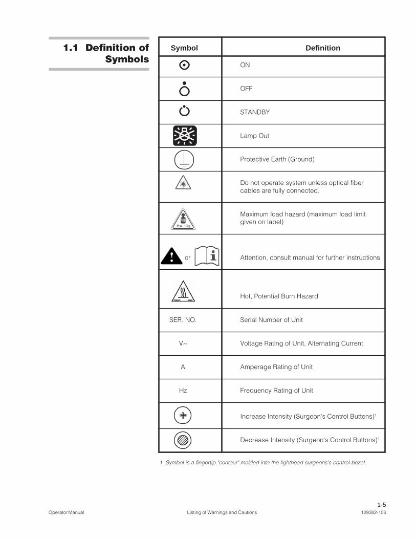
1.1 Definition ofSymbols
Symbol Definition
ON
OFF
STANDBY
Lamp Out
Protective Earth (Ground)
Do not operate system unless optical fibercables are fully connected.
Maximum load hazard (maximum load limitgiven on label)
or Attention, consult manual for further instructions
Hot, Potential Burn Hazard
SER. NO. Serial Number of Unit
V~ Voltage Rating of Unit, Alternating Current
A Amperage Rating of Unit
Hz Frequency Rating of Unit
✙ Increase Intensity (Surgeon's Control Buttons)1
- Decrease Intensity (Surgeon's Control Buttons)1
123456123456123456123456123456123456
1. Symbol is a fingertip "contour" molded into the lighthead surgeons's control bezel.
1-6129382-106 Listing of Warnings and Cautions Operator Manual
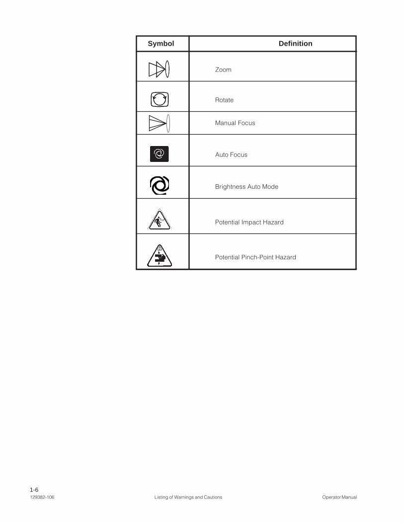
Symbol Definition
Zoom
Rotate
Manual Focus
Auto Focus
Brightness Auto Mode
Potential Impact Hazard
Potential Pinch-Point Hazard

2-1Operator Manual Installation Verification 129382-106
� WARNING – ELECTRICSHOCK HAZARD: Do notremove covers or performservice other than as de-scribed in this operatormanual. Refer servicingto qualified service per-sonnel (MaintenanceManual P764330-226).
� W A R N I N G – I M P A C THAZARD: Do not removescrew from the spring armjoint until the lightheadhas been securely in-stalled onto the springarm. Note: This warningapplies at both installa-tion and de-installationprocedures.
Equipment Drawings showing all of the space and utility requirements weresent to the purchaser after the order for this surgical light was received. Theclearance space shown on the drawing is necessary for proper installation,operation and maintenance of this fixture.
Installation and Uncrating Instructions were furnished with the LightingFixture.
If any of these documents are missing or misplaced, contact STERIS, givingthe serial and model numbers of the equipment. Replacement copies will besent to you promptly.
Before operating the equipment, complete the pre-operation checklist. It isessential to the safe operation and continuing maintenance of this equipmentto verify that the installation is complete and correct. (Refer to Figures 2-1through 2-3 to locate parts.)
INSTALLATION VERIFICATION
2.1 Pre-operationChecklist
2
Tension Screw
Figure 2-1. Tension Screw Locationfor Harmony® Lux Advantage LA 500 and LA 700
Lightheads

2-2129382-106 Installation Verification Operator Manual
Check all suspension joints for compromised integrity, such as loose fasten-ers or components.
Verify that suspension system moves through all articulations smoothlywithout binding. Lightheads and monitors should move smoothly and easily.When positioned, the lighthead and monitor support arms should not drift. Ifbinding or drifting is present in suspension movements, call your STERISservice representative to make adjustments.
Figure 2-2. Check Suspension
Check these and all similar areas for ease ofmovement, as well as suspension integrity
2.1.1 Check SuspensionMovement
� WARNING – PINCHINGHAZARD: Pinch points arecreated during extreme ar-ticulation of the suspen-sion system. Do not placehands on or near the sus-pension knuckle duringlighthead articulations.
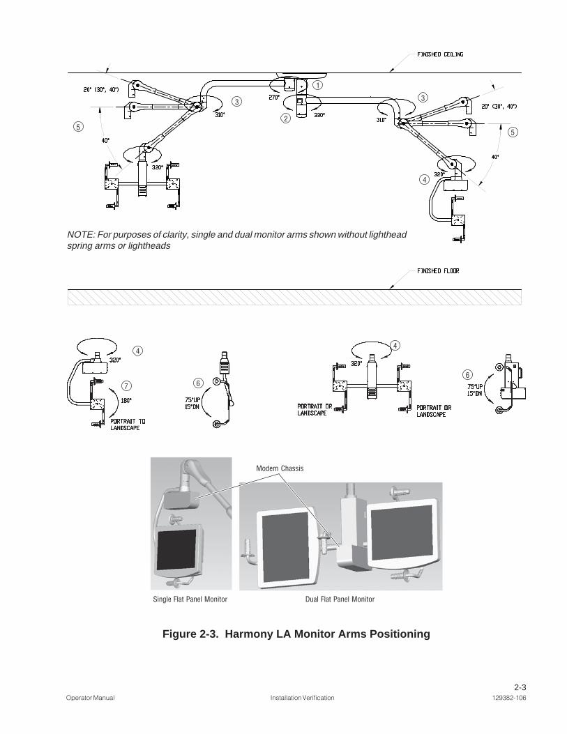
Refer to Figure 2-3. Fiber optic flat panel monitor support arms are capable ofthe following articulations: (1) rotate 270° at the secondary spindle; (2) rotate330° at the central spindle; (3) rotate 310° at the horizontal extension arm; (4)rotate 320° at the yoke transition; (5) move up or down by pivoting at springarm knuckle up to 40° up, and 40° down. Flat panel yoke also allows (6) tiltforward (down) 15° or backward (up) 75° in yoke. The flat panel yoke can beset for either portrait or landscape display (7).
• For additional information, refer to separate operating instructions suppliedwith monitor(s). (Monitor instructions not by STERIS.)
• Power supply and input signals to monitors can be routed through thesuspension wiring from an external video source (external video sources notprovided by STERIS).
• Range of upward motion for spring arm can be adjusted to 20°, 30° or 40°above horizontal to expand storage/parking options when monitors are notin use.
NOTE: If weight or range of motion for flat panel monitor mount system ischanged in any way, refer to INSTALLATION INSTRUCTIONS, P129382-756for procedures to help ensure proper balancing and motion.
2.1.2 Harmony LA FiberOptic Video Enabled
System
2-3Operator Manual Installation Verification 129382-106
5
3
2
1
3
4
5
Figure 2-3. Harmony LA Monitor Arms Positioning
4
7 6
4
6
NOTE: For purposes of clarity, single and dual monitor arms shown without lightheadspring arms or lightheads
Single Flat Panel Monitor Dual Flat Panel Monitor
Modem Chassis

2-4129382-106 Installation Verification Operator Manual
Check Lamp Failure LED: If the LED on any of the lightheads is blinking, oneor both of the fixture’s lamps may have to be replaced. (Refer to SECTION 6,MAINTENANCE.) Verify lamp-out indicator on control center display is visible.
Check Intensity Controls at Each Surgeon's Control: Verify that theintensity level can be increased and decreased at each lighthead using thesurgeon's control buttons (see Figure 2-5).
Figure 2-4. Use Control Center to Check SystemOperation
Verify that electrical power to the control center is on.
Harmony® Lux Advantage LA Control Center: Turn control on by pressing“ON” touch pad. Verify that control cycles through all displays. Return to mainmenu and check intensity levels for each lighthead in the system (See Figure2-4.)
NOTE: Turn power OFF to each lighthead using intensity controls when testingis complete.
Check Lamp Failure Indicators: If any lamp-out graphic on the control centerdisplay is visible, one or both of the indicated lighthead's lamps may have tobe replaced. (Refer to SECTION 6, LAMP REPLACEMENT.) Verify lamp failure LED onlighthead housing is blinking.
2.1.3 Check SystemOperation

2-5Operator Manual Installation Verification 129382-106
Turn the control center ON. Install video camera in lighthandle(see SECTION 3.9, VIDEO CAMERA INSTALLATION OR REMOVAL). Press the CameraControl button on the touch pad to select the Camera Control Menu, selectand turn ON the camera. (See Figure 2-6.)
Video: Verify that a clear signal is reaching the video display device(monitor) from the camera. (Check cable connection between controlcenter and monitor, if necessary.)
Control Center: Verify zoom, rotation and focus functions with the controlcenter switches. Select Camera Menu 2; verify Gain controls (if neces-sary), verify Freeze Frame function, verify Time and Date displays (ifnecessary).
Optional Wireless Hand-held Control: Verify zoom, rotation and focusfunctions with the optional wireless control. (Check batteries in control ifnecessary.)
NOTE: Transmitter on optional wireless control must be within 15 feet anddirected within 50° of receiver on control center.
Optional Foot Control: Verify zoom and rotation functions with theoptional foot control. (Check cable connection between foot control andcontrol center, if necessary.)
2.1.4 Check OptionalVideo Camera Operation
Figure 2-5. Use Surgeon's Control Buttons to Check LightheadIntensity Operation (Harmony LA 500 Lighthead Shown)
Surgeon'sControlButtons

2-6129382-106 Installation Verification Operator Manual
Figure 2-6. Camera Control Menus
CAMERA CONTROL 1 2 3 4
SLOW FASTZOOM SPEED
SLOW FASTFOCUS SPEED

2-7Operator Manual Installation Verification 129382-106
Refer to Figure 2-7.
The Harmony LA Surgical Lighting and Visualization System can include up totwo monitor arms on a single central mount. Verify smooth and easy movement(without binding or drifting) through the monitor arm(s) ranges of articulations.Verify that monitor, or monitors, receive video signals.
Figure 2-7. Harmony LA Monitor Support Arm(Typical Dual Flat-Panel Monitor Arm Shown)
2.1.5 Check OptionalMonitor Support Arms

2-8129382-106 Installation Verification Operator Manual
Refer to Figure 2-8.
Verify that DeepSite™ lighthead and arm move freely and easily through rangeof articulations.
Turn lighthead ON at control center, verify intensity levels, and verify patternadjustment function.
Inboard Hub ofCentra Mount
Lighthead
SuspensionKnuckle
Adjustable PositioningGooseneck
Figure 2-8. DeepSite Lighthead and Arm
Adjustable (lower)Suspension Arm
Spring Arm
2.1.6 Check OptionalDeepSite Lighthead

2-9Operator Manual Installation Verification 129382-106
Figure 2-9. DeepSite Ceiling-mounted Illuminator
Lamp HousingLock Handle*
Service Access Latch(to Circuit Breakers)
Refer to Figure 2-9.
A ceiling-mounted component contains the light source for the optionalDeepSite lighthead. Verify lamp module is installed (see Section 6) and circuitbreakers are in the ON position.
* NOTE: Lamp-life indicator (on wall control)automatically resets to New Lamp if thelamp housing lock lever is open for 25seconds while the circuit breaker is ON.
2.1.7 Check OptionalDeepSite Ceiling-
mounted IlluminatorHousing
2-10129382-106 Installation Verification Operator Manual
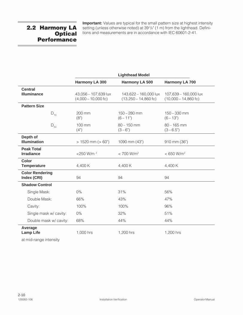
Important: Values are typical for the small pattern size at highest intensitysetting (unless otherwise noted) at 39 3/8" (1 m) from the lighthead. Defini-tions and measurements are in accordance with IEC 60601-2-41.
2.2 Harmony LAOptical
Performance
Lighthead Model
Harmony LA 300 Harmony LA 500 Harmony LA 700
CentralIlluminance 43,056 – 107,639 lux 143,622 – 160,000 lux 107,639 – 160,000 lux
(4,000 – 10,000 fc) (13,250 – 14,860 fc) (10,000 – 14,860 fc)
Pattern Size
D10 200 mm 150 – 280 mm 150 – 330 mm(8") (6 – 11") (6 – 13")
D50 100 mm 80 – 150 mm 80 – 165 mm(4") (3 – 6") (3 – 6.5")
Depth ofIllumination > 1520 mm (> 60") 1090 mm (43") 910 mm (36")
Peak TotalIrradiance <250 W/m 2 < 700 W/m2 < 650 W/m2
ColorTemperature 4,400 K 4,400 K 4,400 K
Color RenderingIndex (CRI) 94 94 94
Shadow Control
Single Mask: 0% 31% 56%
Double Mask: 66% 43% 47%
Cavity: 100% 100% 96%
Single mask w/ cavity: 0% 32% 51%
Double mask w/ cavity: 68% 44% 44%
AverageLamp Life 1,000 hrs 1,200 hrs 1,200 hrs
at mid-range intensity

3-1Operator Manual Operating Instructions 129382-106
OPERATING INSTRUCTIONS
The wall-mounted Harmony™ Lux Advantage LA Control Center allows theuser to adjust the lighthead intensity level (brightness) by pressing amembrane switch (or "button"). An identifying number on the controldisplay corresponds to the same number on the lighthead suspensionarm. Additionally, each lighthead has its own “onboard” intensity controls,located above the lighthandle adjacent to the lens. These controls are usuallyreferred to as the surgeon's control buttons or as the surgeon's control (seeFigure 3-2).
To Adjust Lighthead Intensity Levels:
1. Press ON touch pad.
2. Intensity levels for one or two lightheads can be controlled from one controlcenter. A lighthead’s surgeon's control buttons adjust the intensity level forthat lighthead.
Important: Avoid control center faults. Do not continuously press and holdany control center button for more than 15 seconds.
Control Center (see Figure 3-1)
1. Use the “Select Light” touch pads to move the display indicator up ordown until it aligns with the appropriate lighthead.
2. Once the lighthead is selected, press either the button to increase light
intensity level, or the button to decrease light intensity level.
3. If “All Lights” is selected, intensity for all lightheads in the system isincreased or decreased simultaneously.
NOTE: For longer lamp life, use lowest intensity level suitable for surgicalprocedure.
3.1 IntensityControls
� WARNING – EXPLOSIONHAZARD: Do not use inthe presence of flammableanesthetics.
3
Figure 3-1. LA Control Center Main Menu
Indicates SelectedLighthead
Lighthead IntensityStatus
Lamp StatusIndicators

3-2129382-106 Operating Instructions Operator Manual
LA 300 Lighthead LA 500 Lighthead Shown
Surgeon'sControl Buttons
Figure 3-2. Lighthead Surgeon's Control Buttons
Surgeon's Intensity Control Buttons (See Figure 3-2)
1. Grasp the handle of the appropriate lighthead. A ring of membrane buttons(bumps) are located on the control bezel adjacent to the lighthead lens.
2. Press any of the surgeon's intensity control buttons molded with "+"symbols to increase the lighthead intensity. Press any of the surgeon'scontrol buttons molded with "-" symbols to decrease lighthead intensity.
NOTE: For longer lamp life, use lowest intensity level suitable for surgicalprocedure.
3. To turn lighthead OFF:
a. At the control center: press the “Select Light” button until indicatorpoints to the appropriate lighthead on the display. Press the “De-crease Intensity” button until the light goes out.
b. At the lighthead, press and hold any of the dimpled membranebuttons until the light goes out.
NOTE: Press the decrease intensity button (-) on the lightheadsurgeon's control for an additional five seconds, to turn off all light-

3-3Operator Manual Operating Instructions 129382-106
Harmony LA 300 Lighthead Harmony LA 500/700 Lightheads
Pattern Change Capability No Yes
Backup Lamp No Yes
Video Camera Capability No Yes
Handle Position Offset1 Central2
3.2 Comparison ofLightheadFeatures
1 Harmony LA 300 lighthead is equipped with a sectional-circumference control bezel,providing two sets of surgeon's intensity control buttons.
2 Harmony LA 500 and LA 700 lightheads are equipped with a full-circumference bezel,providing four sets of surgeon's intensity control buttons.
3-4129382-106 Operating Instructions Operator Manual
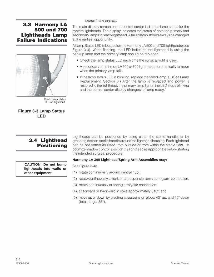
Check Lamp StatusLED on Lighthead
3.3 Harmony LA500 and 700
Lightheads LampFailure Indications
Figure 3-3.Lamp StatusLED
3.4 LightheadPositioning
CAUTION: Do not bumplightheads into walls orother equipment.
heads in the system.
The main display screen on the control center indicates lamp status for thesystem lightheads. The display indicates the status of both the primary andsecondary lamps for each lighthead. A failed lamp should always be changedat the earliest opportunity.
A Lamp Status LED is located on the Harmony LA 500 and 700 lightheads (seeFigure 3-3). When flashing, the LED indicates the lighthead is using thebackup lamp and the primary lamp should be replaced.
• Check the lamp status LED each time the surgical light is used.
• A secondary lamp inside LA 500 or 700 lightheads automatically turns onwhen the primary lamp fails.
• If the lamp status LED is blinking, replace the failed lamp(s). (See LampReplacement, Section 6.) After the lamp is replaced and power isrestored to the lighthead, the primary lamp lights, the LED stops blinkingand the control center display changes to "lamp ready."
Lightheads can be positioned by using either the sterile handle, or bygrasping the non-sterile handle around the lighthead housing. Each lightheadcan be positioned as listed from outside or from within the sterile field. Tooptimize shadow control, position the lighthead as appropriate before startingthe intended surgical procedure.
Harmony LA 300 Lighthead/Spring Arm Assemblies may:
See Figure 3-4a.
(1) rotate continuously around central hub;
(2) rotate continuously at horizontal suspension arm/ spring arm connection;
(3) rotate continuously at spring arm/yoke connection;
(4) tilt forward or backward in yoke approximately 310°; and
(5) move up or down by pivoting at suspension elbow 40° up, and 45° down(total range: 85°).

3-5Operator Manual Operating Instructions 129382-106
Figure 3-4b. Harmony LA 500 and 700 Lighthead Positioning
CAUTION: Do not bumplightheads into walls orother equipment.
Figure 3-4a. Harmony LA 300 Lighthead Positioning
Unlimited
Unlimited1
215°Typical
5
85°Typical
5
Unlimited3
310°4
Harmony LA 500 and LA 700 Lighthead/Spring Arm Assemblies may:
See Figure 3-4b.
(1) rotate continuously around central hub;
(2) rotate continuously at horizontal suspension arm/ spring arm connection;
(3) rotate continuously at spring arm/yoke connection;
(4) tilt forward or backward in yoke approximately 310°; and
(5) move up or down by pivoting at suspension elbow 15° up, and 85° down(total range: 100°).

3-6129382-106 Operating Instructions Operator Manual
3.5 Harmony LA500 and 700
Lighthead PatternAdjustment
Figure 3-5. Light Pattern Adjustment
The illumination pattern for Harmony LA 500 and 700 lightheads can beadjusted to any size between the maximum diameter and minimum diameter.
• Rotate the handle clockwise to decrease pattern size.
• Rotate the handle counterclockwise to increase pattern size.
NOTE: Typical lighthead positioning is above and slightly behind the surgeon'sright or left shoulder.
Rotate Handle to Decrease
Pattern Rotate Handle
to Increase Pattern

3-7Operator Manual Operating Instructions 129382-106
3.6 Lighthandleand Lighthandle
Cover
3.6.1 Installing andUsing Lighthandle and
Lighthandle Cover
WARNING–POSSIBLEPATIENT INJURY HAZ-ARD: Failure to engagethe lighthandle covercompletely may result incover falling from light-head during the proce-dure.
Figure 3-6. Standard Handle
Lighthandles are used to position Harmony LA lightheads, allow access tointensity control on each lighthead, and to adjust lighthead pattern size. Toavoid accidental contact with the non-sterile surgeon's control buttons, thelighthandle should always be used with a disposable, sterile lighthandle cover(available separately from STERIS).
• If the lighthandle adapter is not already in place, align the tab on the adapterwith the channel in the mounting ring and thread the adapter in until fullyengaged. (See Figures 3-6a and 3-6b.)
NOTE: The LA 300 lighthead does not have a separate adapter. Adapter ispermanently integrated into lighthandle assembly.
• Prior to starting a procedure, ensure that the lighthandle is in place. Installthe lighthandle by threading onto the adapter and firmly tightening (seeFigure 3-6c).
• Remove the sterile lighthandle cover from its packaging and install onto thelighthandle (see Figure 3-6d).
NOTE: A standard lighthandle cover is used for Harmony LA 300, LA 500 andLA 700 lighthead lighthandles.
. . .continued
Surgeon's Intensity Align Tab on Handle Adapter withControl Buttons channel in Mounting Ring
Lighthandle Adapter*
* Lighthandle adapter not a feature for 300 lightheads.
Figure 3-6b. Lighthandle
Lighthandle Adapter*
Figure 3-6a. Install Standard Lighthandle
Figure 3-6c.Disposable
Lighthandle Cover
Install Disposable Lighthandle Cover Immediately Before Procedure
Push Cover Completely onto Lighthandle**
** Same cover used for Harmony LA 300, LA 500, and LA 700 lightheads.
Align lighthead and spring arm asshown when installing sterile covers.
Figure 3-6d.

3-8129382-106 Operating Instructions Operator Manual
3.7 Harmony LAMonitor Arms
3.6.2 Metal SterilizableHandle
WARNING – STERILITYASSURANCE HAZARD:Do not use the surgeon’scontrol buttons unless adisposable sterile coveris installed. If thesterilizable lighthandle(metal) is used without adisposable cover, thesurgeon’s control but-tons are not protected bya sterile covering.
• The lighthandle can be removed for cleaning or sterilization by unscrewingit from the handle adapter. The lighthandle can be sterilized using standardhospital cycles. Do not use the lighthead during a sterile procedure unlessa disposable cover is installed on the lighthandle.
The metal sterilizable handle is used to position the LA lighthead and to adjustthe light pattern size. The sterilizable handle may be used in place of adisposable sterile lighthandle cover.
The plastic lighthandle should be removed prior to installing the metalsterilizable handle. To do so, simply unscrew it from the threaded handleadapter.
Prior to starting a procedure, install a clean, sterilized metal handle byscrewing it onto the threaded handle adapter. Ensure handle is firmlytightened prior to use. The gap between the flange on the metal sterilizablehandle and the surgeon's control buttons prevent accidental contact with thenon-sterile surface of the buttons.
The metal sterilizable handle can be removed for sterilization by unscrewingit from the adapter.
The metal sterilizable handle can be sterilized using standard hospital steamcycles intended for lumens. Always sterilize handle between surgical proce-dures.
The Harmony LA lighting system can be equipped with one or two monitorsupport arms.
Monitor arms can be included in the Harmony LA lighting system either as theuppermost arm on the central spindle, or as the secondary spindle arm.
Refer to Figure 3-7b. Fiber optic flat panel monitor support arms are capableof the following articulations: (1) rotate 270° at the secondary spindle; (2)rotate 330° at the central spindle; (3) rotate 310° at the horizontal extensionarm; (4) rotate 320° at the yoke transition; (5) move up or down by pivoting atspring arm knuckle up to 40° up, and 40° down. Flat panel yoke also allows(6) tilt forward (down) 15° or backward (up) 75° in yoke. The flat panel yokecanbe set for either portrait or landscape display (7). CRT allows (6) tilt 0-13°.

3-9Operator Manual Operating Instructions 129382-106
• For additional information, refer to separate operating instructions suppliedwith monitor(s). (Monitor instructions not by STERIS.)
• Power supply and input signals to monitors can be routed throughthesuspension wiring from an external video source (not by STERIS).
• Signal and monitor power wiring is provided at the installation with eachmonitor support arm.
• Input signals to monitors can be routed through the suspension wiring froman external video source (not by STERIS).
• Range of upward motion for spring arm can be adjusted to 20°, 30°, or 40°above horizontal, to expand storage/parking options when monitors are notin use.
NOTE: If weight or range of motion for flat panel monitor mount system ischanged in any way, refer to INSTALLATION INSTRUCTIONS, P129382-756 for procedures to help ensure proper balancing and motion.
Figure 3-7a. Harmony LA Monitor Arms
Adjust CRT MonitorShelf by Loosening/
Tightening Knob
CRT Monitor Support Arm
Harmony LA CRT Monitor Arms
Dual Flat Panel Monitor Support Arm with Monitors in Portrait (left) and Landscape (right) Positions
Single Flat Panel Monitor Support Armwith Monitor in Landscape Orientation
Harmony LA Flat Panel Monitor Arms

3-10129382-106 Operating Instructions Operator Manual
Figure 3-7b. Harmony LA Monitor Arms
4
7 6
4
6
Single Flat Panel Monitor Dual Flat Panel Monitor
Modem Chassis
5
3
2
1
3
4
5
NOTE: For purposes of clarity, single and dual monitor arms shown without lightheadspring arms or lightheads

3-11Operator Manual Operating Instructions 129382-106
Important: Use new covers for each handle for each procedure where themonitor is used.
Covers are sterile and shipped in a protective wrapper. Wear sterile gloveswhen removing covers from packaging. When installing covers, follow sterilityassurance procedures as outlined by facility protocols.
• Refer to Figure 3-8A for current production handles.
• Refer to Figure 3-8A for out-of-porduction production handles.
Procedure:
1. Remove cover from packaging.
2. Pull the cover until it fully covers the handle.
NOTE: Step 3 applies only to out-of-production handles.
3. Refer to Figure 3-8b. Pull closure tie until tight enough to prevent cover fromslipping down the handle.
4. Repeat procedure for second handle(s).
3.8 Install FlatPanel Monitor YokeHandle Disposable
Sterile Covers
Figure 3-8a. Installing Disposable Sterile Monitor Handle Covers(Current Production Handles)
WARNING – BIOHAZARD:
• Sterile disposables areintended for single useonly.
• Universal precautionsmust be observedwhen disposing of anysingle use disposableitem.
Monitor Positioning Guide Disposable Cover Over Handle (Contoured Style) Handle Until Handle is Fully
Disposable Sterile Cover Covered
Guide Disposable Cover Over Handle Until Handle is Fully
Covered

3-12129382-106 Operating Instructions Operator Manual
Disposable Sterile Cover Closure Tie Monitor YokeHandle
Guide DisposableCover Over Handle
Until Handle isFully Covered
Cut Off and Discard ExcessClosure Tie, If Desired
Cut Off and Discard ExcessClosure Tie, If Desired
Figure 3-8a. Installing Disposable Sterile Monitor Handle Covers(Out-of-Production Handles)
3-13Operator Manual Operating Instructions 129382-106
3.10 InstallCamera
Disposable SterileCover
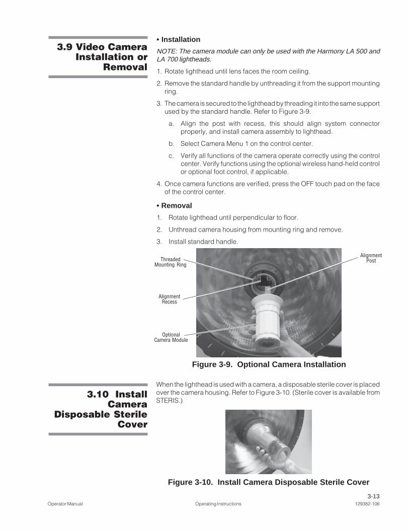
When the lighthead is used with a camera, a disposable sterile cover is placedover the camera housing. Refer to Figure 3-10. (Sterile cover is available fromSTERIS.)
3.9 Video CameraInstallation or
Removal
Figure 3-9. Optional Camera Installation
• Installation
NOTE: The camera module can only be used with the Harmony LA 500 andLA 700 lightheads.
1. Rotate lighthead until lens faces the room ceiling.
2. Remove the standard handle by unthreading it from the support mountingring.
3. The camera is secured to the lighthead by threading it into the same supportused by the standard handle. Refer to Figure 3-9.
a. Align the post with recess, this should align system connectorproperly, and install camera assembly to lighthead.
b. Select Camera Menu 1 on the control center.
c. Verify all functions of the camera operate correctly using the controlcenter. Verify functions using the optional wireless hand-held controlor optional foot control, if applicable.
4. Once camera functions are verified, press the OFF touch pad on the faceof the control center.
• Removal
1. Rotate lighthead until perpendicular to floor.
2. Unthread camera housing from mounting ring and remove.
3. Install standard handle.
Figure 3-10. Install Camera Disposable Sterile Cover
AlignmentThreaded Post
Mounting Ring
AlignmentRecess
OptionalCamera Module

3-14129382-106 Operating Instructions Operator Manual
3.11 Video CameraOperation
The optional video camera is integrated into a removable handle that can befitted to any Harmony LA 500 or LA 700 lighthead. Whenever the video optionis used, a separate sterile disposable cover must be fitted over the camerabefore each procedure (see SECTION 3.10, INSTALL CAMERA DISPOSABLE STERILE
COVER). This cover allows the camera to be grasped and used in the same wayas a standard handle, including positioning the lighthead for optimal illumina-tion, adjusting lighthead intensity and pattern size, as well as positioning thevideo image field for the best view of the procedure. The sterile cover must beremoved from the camera and discarded after each procedure.
Once the video camera module has been installed in the lighthead, the cameramay be turned on at the control center by selecting the camera menu and thenselecting camera on. Once the camera is initialized, its functions can becontrolled by the wall control, the optional hand-held wireless control, or theoptional foot switch. Full control of all camera functions is available throughmenus on the control center. The remote control and foot switch providecontrol of a limited set of the most commonly used features. The list of camerafeatures and how they may be controlled is summarized in the table below:
Control Location
Feature Control Center * Remote Control Foot Switch
Power X (1)
Zoom X (1) X X
Rotate X (1) X X
Auto/Manual X (1)Brightness
Brightness X (1)
Auto/Manual X (1) XFocus
Focus X (1) X
Auto/Manual X (2)White Balance
Red-Gain X (2)
Blue-Gain X (2)
Live/Freeze X (2)Picture
Time Display X (2)
Date Display X (2)
Set Time X (3)
Set Date X (3)
Zoom Speed X (4)
Focus Speed X (4)
* The number in parentheses in the Control Center Column is the number of thecamera control menu.

3-15Operator Manual Operating Instructions 129382-106
The control center functions by transmitting signals via a control cable to thecamera located in the lighthead.
The optional wireless control functions by transmitting infrared signals to thecontrol center. To initiate camera functions with either control, press theappropriate touch pad on the control face panel. The hand-held control’s IR(infrared) transmitter must be within approximately 15 feet (4.5 m) and 50° ofthe control center receiver.
NOTE: The symbols used for Zoom and Focus are "+" and "-" for the IR remotecontrol and the foot control. For the wall control, the symbols "<" and ">" areused to adjust Zoom and Focus.
Refer to Figure 3-11a. The control touch pads are used to control the followingcamera functions:
Zoom – for determining the level of detail visible in the image field. The Zoomfunction adjusts the image field continuously between two extremes:
(Telephoto). At extreme telephoto, the camera captures an image showinggreat detail in a small area.
NOTE: At extreme telephoto, any motion of the lighthead/camera may beexaggerated (jerky). The field of focus has little depth at this extreme, forcingthe Auto Focus function (if enabled) to refocus the camera when any object(such as a hand) enters the image field, or if camera position is adjusted. Thecamera is also sensitive to light level changes at extreme telephoto.
» Camera Operation
Figure 3-11. Camera Control Menus 1 and 2
ControlCenter Remote
–
ControlCenter Remote
+
Figure 3-11a Figure 3-11b

3-16129382-106 Operating Instructions Operator Manual
(Wide Angle). At extreme wide angle, the camera captures a large image withless detail than telephoto.
NOTE: At extreme wide angle, the image field possesses a greater depth offocus and less sensitivity to light level changes.
Rotate – Use this function to change orientation of the video field. Image fieldcan be rotated in either clockwise or counterclockwise directions.
Bright – Use this function to affect the overall brightness (or darkness ) of thevideo image. The Bright control can be set to adjust itself automatically.
Manual Focus ––––– Use this function to manually set the focus. The Auto Focusfunction must be toggled off to enable manual focusing. Adjust the clarity offocus by pressing the + or – touch pads.
Zoom is defined by two extremes: short, indicating little zoom has been used;or long, indicating zoom has been extended toward its maximum limit. Overalldistance between the object and the camera, plus the length of zoom, affectsthe camera's ability to achieve a sharp focus. The greater the zoom length, theless capability the camera has to establish a sharp focus.
• The focus slider bar on the control center also has two extremes, theseextremes have been labeled near and far. The focus indicator slides onlyas far as required to establish a sharp focus.
• When sharp focus cannot be achieved, the focus indicator cannot slide allthe way to the near setting.
Example: When the indicator cannot be moved left (toward near), the camerahas been forced beyond its optical focusing limit. In this case, adjust to ashorter zoom length, and try focusing the image again.
NOTE: + touch pad moves the lens slightly closer to subject; – touch padmoves the lens slightly away from subject.
Auto Focus – Use this function to toggle Auto Focus on or off. When AutoFocus is ON, the camera automatically focuses on the object in the imagefield closest to the camera lens. When Auto Focus is turned OFF, the cameramaintains focus on the last object upon which it was focused, until Auto Focusis turned back on.
NOTE: It may be necessary to toggle Auto Focus OFF when using the cameraat extreme telephoto (close up), to prevent the camera from refocusing onhands and other objects introduced into the image field while video imagingprocedures.
Refer to figure 3-11b, and advance control center to camera control screen 2for the following features:
Red Gain/Blue Gain – These controls are used to adjust image color settings,and are intended to allow the user to compensate for changes in colortemperature provided by differing light sources. The gain control can be setto adjust automatically.
Refer to Figure 3-12a, camera control screen 3 is one of four screens used to
ControlCenter Remote
+
ControlCenter Remote
–

3-17Operator Manual Operating Instructions 129382-106
control video camera parameters:
1. Up/down arrows are used to select the field to be changed.
2. Right/left arrows are used to change the value of the selected field.
3. The Update Clock control is used to set the camera’s real time clock to thesetting in the date and time fields.
Refer to Figure 3-12b, camera control screen 4 is one of four screens used tocontrol video camera parameters.
1. Press right-dot key below ‘Lights’ icon to advance display to the light controlscreen.
2. Press center-dot key below ‘Menu 1’ icon to advance display to cameracontrol 1 screen.
3. User-selected options for focus and zoom speed are stored in memory, andare restored after a power interruption.
NOTE: These options are reset to default values when a “Clear User Settings”type reset is issued.
Figure 3-12. Camera Control Menus 3 and 4
Figure 3-12a Figure 3-12b

3-18129382-106 Operating Instructions Operator Manual
Figure 3-13. Optional Video Controls
» Optional Foot Control The foot control functions by transmitting signals through a cable connectedto the control center. When the foot control is used, the cable should be routedto avoid surgical personnel foot traffic. The foot control is intended to allowpersonnel within the sterile field to operate the zoom and rotation functions ofthe camera.
Foot control is used to control zoom and rotation functions. Refer toFigure 3-13. Press on appropriate sides of foot pedals to activate foot controlfunctions. Functions controlled through the foot control unit are identical tothose controlled through the optional hand-held wireless control or controlcenter.
Amsco® SQ240 SurgiVisionTM
Surgical Lighting and Video System
ZOOM ROTATE
Optional Hand-held WirelessRemote Control
Optional Foot Control
3-19Operator Manual Operating Instructions 129382-106
Observe the following guidelines to aid in maximizing video imaging effective-ness.
• Energize the light at medium setting on the control center, and position thelighthead approximately 39" (1000 mm) from the surgical site.
• Using the hand-held remote, or the control center, zoom in or out (+ or -) untilthe desired image fills the viewing screen of the monitor.
NOTE: Zooming completely out causes image distortion within the illumi-nated area.
If the light pattern (white circle) does not fill the monitor’s screen (shadedsquare), the image inside the pattern may be distorted.
Reposition the camera to orient the focal point (center of the desired image)at the center of the viewing screen.
Adjust zoom and rotation as needed:
• The camera may be zoomed to the full 40x zoom (10x optical, 4x digital) androtation orientation adjusted as needed.
• Clockwise and/or counterclockwise orientation is adjusted by using thecurved arrow(s) on the hand-held control, the control center or the optionalfoot control.
As instruments are introduced to and removed from the surgical field, the autofocus attempts to focus on the nearest object, possibly causing the image toblur intermittently. To prevent this effect, once the camera has been positionedand focused onto the surgical site, the manual focus mode may be engagedto maintain image clarity during the procedure.
For deep cavity illumination, it may be necessary to engage the manual focusto focus beyond the nearest object (i.e., the surface area surrounding theincision) so that the desired image can be viewed clearly.
3.12 Guidelines forMaximizing Video
Image
» Engage Manual Focus
Position Light Pattern in Center of VideoImage to Avoid Distortion
12345678901234567890123456789012123456781234567890123456789012345678901212345678123456789012345678901234567890121234567812345678901234567890123456789012123456781234567890123456789012345678901212345678123456789012345678901234567890121234567812345678901234567890123456789012123456781234567890123456789012345678901212345678123456789012345678901234567890121234567812345678901234567890123456789012123456781234567890123456789012345678901212345678123456789012345678901234567890121234567812345678901234567890123456789012123456781234567890123456789012345678901212345678123456789012345678901234567890121234567812345678901234567890123456789012123456781234567890123456789012345678901212345678123456789012345678901234567890121234567812345678901234567890123456789012123456781234567890123456789012345678901212345678123456789012345678901234567890121234567812345678901234567890123456789012123456781234567890123456789012345678901212345678123456789012345678901234567890121234567812345678901234567890123456789012123456781234567890123456789012345678901212345678123456789012345678901234567890121234567812345678901234567890123456789012123456781234567890123456789012345678901212345678123456789012345678901234567890121234567812345678901234567890123456789012123456781234567890123456789012345678901212345678123456789012345678901234567890121234567812345678901234567890123456789012123456781234567890123456789012345678901212345678123456789012345678901234567890121234567812345678901234567890123456789012123456781234567890123456789012345678901212345678123456789012345678901234567890121234567812345678901234567890123456789012123456781234567890123456789012345678901212345678
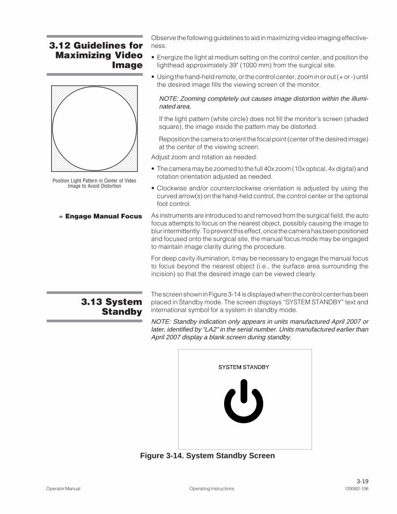
3.13 SystemStandby
The screen shown in Figure 3-14 is displayed when the control center has beenplaced in Standby mode. The screen displays “SYSTEM STANDBY” text andinternational symbol for a system in standby mode.
NOTE: Standby indication only appears in units manufactured April 2007 orlater, identified by “LA2” in the serial number. Units manufactured earlier thanApril 2007 display a blank screen during standby.
Figure 3-14. System Standby Screen

3-20129382-106 Operating Instructions Operator Manual
Refer to Figure 3-15.
• Intensity Level Status - This shows the current intensity level of theDeepSite™ light.
• Lamp Life Status - The DeepSite lighthead uses a high-intensity Xenonlamp module as a light source. The Harmony LA system can track theapproximate life remaining for this lamp module and display it at the controlcenter.
NOTE: Refer to Lamp Replacement procedure in Section 6 of this manualwhen it becomes necessary to change the DeepSite lamp.
3.14 DeepSiteControl Center
Status Indicators
3.15 DeepSiteLighthead
Positioning
Figure 3-15. DeepSite Control Center Indicators
DeepSite Intensity StatusIndicator
DeepSite Lamp LifeStatus Indicator
Figure 3-16. Lighthead Positioning Gooseneck
LightheadPositioningGooseneck
New Lamp Spent Lamp
Approximate Lamp LifeUsed/Remaining
The DeepSite lighthead positioning gooseneck (see Figure 3-16) can beadjusted into a stable curved position. Lighthead may also: (1) rotate 340°around vertical suspension tube; (2) rotate 360° around centra mount; (3)move up or down by pivoting at suspension fork 15° up, and 90° down untilvertical (i.e., full movement up and down through 105°).
WARNING - PINCHINGHAZARD: Pinch pointsare created during ex-treme articulation of thesuspension system. Donot place hands on ornear the suspensionknuckle during lightheadarticulations.
CAUTION: Do not bumplightheads into walls orother equipment.

3-21Operator Manual Operating Instructions 129382-106
The light pattern size is adjusted by grasping the lighthead with one hand andgently rotating in a clockwise (larger) or counterclockwise (smaller) direction.Refer to Figure 3-17.
3.15 DeepSitePattern
Adjustment
Figure 3-17. Pattern Size Adjustment at Lighthead
Rotate this Section ofLighthead to AdjustLight Pattern Size
Minimum DiameterMaximum Diameter
WARNING - PERSONALINJURY HAZARD: Avoidlooking directly at high-intensity light, whetherat the lamp, directly atthe lighthead, or fiberoptic cable. Eye injurymay result.

3-22129382-106 Operating Instructions Operator Manual
3.17 DisposableSterile Sleeve
Each time the lighting system is used for a surgical procedure, a sterilesleeve should be used to cover the lighthead and adjustable suspensionarm. Refer to Figure 3-18.
1. Remove protective packaging from the sleeve.
2. Slip the sleeve over the lens holder end of the lighthead.
3. Securely fit the sleeve's end ring to the lighthead's lens cover. Verify thatthe end ring is snug (parallel) to the lens cover.
4. Slowly unfold the sleeve until the suspension arm is covered to theknuckle.
NOTE: Allow enough slack in the sleeve for lighthead positioning.
5. Once the sleeve is fully unfolded, and a suitable area of the lighthead andsuspension is covered, tear the adhesive tape off the sleeve and removethe white backing. Wrap the tape tightly around the sleeve, anywherealong the suspension arm assembly.
NOTE: The tape must be securely wrapped around the sleeve, only. Thetape MUST NOT be applied to the surface of the suspension arm.
IMPORTANT: The sterile sleeve is intended as a single-use item. The sleevemust be removed from lighting fixture at the end of each procedure anddisposed of following facility waste protocols.
WARNING – BIOHAZARD:Sterile sleeve is intendedfor single use only.
WARNING – BIOHAZARD:Universal precautionsmust be observed whendisposing of the sterilesleeve.
Sleeve
AdhesiveTape
LightheadLens Cover
AdjustableSuspension
Arm
Figure 3-18. Fit DisposableSterile Sleeve to Lighthead
Knuckle

3-23Operator Manual Operating Instructions 129382-106
The ambient light fixture accessory can be installed at the time the HarmonyLA lighting system is installed, or can be added later to a previously installedsystem.
3.18 AmbientLight Fixture
The ambient light provides low-level, general illumination in the surgical suite.Illumination from the ambient light fixture can be configured to operatemanually (turned on or off at the Harmony LA Control Center), or the ambientlight can be configured to operate automatically (turns off when any systemlighthead is turned on and turns on when all system lightheads are turned off).When configured for automatic operation, the ambient light can still bemanually turned on or off at the control center.
NOTE: Ambient light fixture provides eitehr white or green light (not both)depending on option orderd.
3.18.1 Ambient LightOperation Overview
Once the ambient light fixture has been installed, if must be configured for usewith the Harmony LA lighting system. Refer to Figure 3-19.
1. Access the system menu by pressing the system menu button on thecontrol center.
2. Select “Ambient Light Installed?” and change to “Yes.”
• “Ambient Light Mode” selection should appear on the system menuscreen.
• Check mark should appear in the check box next to “Ambient Light,”under “Installed Components” (near the bottom of the system menu).
3.18.2 Configuring andUsing the Ambient Light
Figure 3-19. System Menu

3-24129382-106 Operating Instructions Operator Manual
3. Refer to Figure 3-20. Press the manual activation switch. Observe theambient light fixture (at the perimeter of the ceiling canopy of the HarmonyLA suspension system) and verify that the light turns on and off.
4. Select “Ambient Light Mode, Auto” to configure the ambient light to turn offwhen any system lightheads are turned on, and turn on when all systemlightheads are turned off.
• When using the “Auto” configuration and all system lightheads are off, theambient light remains on until the control center is placed in Standby.
• When using the “Auto” configuration, but the ambient light was turned onor off manually, the automatic feature resets once the light fixtureundergoes one full on/off cycle.
IMPORTANT: If the ambient light fixture lamp fails, refer lamp replacement toa STERIS or STERIS-trained service technician.
Figure 3-20. Configure Ambient Light
WARNING – ELECTRICSHOCK HAZARD: Ambi-ent light kit operates froma 100, 120, or 240 VACpower source in the ceil-ing. Refer any servicingto qualified service per-sonnel.

3-25Operator Manual Operating Instructions 129382-106
3.19 ACT EnabledSystem
The Harmony LA Lighting and Visualization System can be configured tooperate using voice activated controls or touch-panel displays. The STERIS-provided portion of this system is an interface point between Harmony LAsystem and the operating room control system. Refer to the operating manualand technical specifications provided with the operating room control systemfor specific details.
NOTE: Harmony System must be ON when operating with Operating RoomControl System (ORCS).
Verify Harmony LA system with STERIS ACT Interface configuration asfollows:
1. Access the System Menu by pressing the System Menu button on thecontrol center. Refer to Figure 3-21.
2. “STERIS ACT INTERFACE” selection should appear on the System Menuscreen.
• Check mark should appear in the check box next to “STERIS ACTINTERFACE,” under “Installed Components” (at the bottom of the SystemMenu).
Figure 3-21. Enable ACT Interface

4-1Operator Manual Cleaning the Equipment 129382-106
4• Pail
• Sponge
• Cloth Wipes
• Rubber Gloves
• Mild Household Detergent (e.g., Dishwashing Liquid)
• Disinfectant cleaners such as:
» Germicidal Surface Wipes Disinfecting / Deodorizing / Cleaning Wipes
Listed disinfectant cleaning products are available from STERIS for use onthis equipment.
CLEANING THE EQUIPMENT
4.1 CleaningEquipment
1. Registered trademark of Purdue Pharma L.P.
WARNING – PERSONALINJURY HAZARD: Do notattempt to clean lightheadunless power is turned offand the lighthead hascooled sufficiently.
CAUTION – POSSIBLEEQUIPMENT DAMAGE:
• Use of any disinfectant so-lution OTHER than thoselisted below may cause dis-coloration or deformationon the lens surface: Germi-cidal Surface Wipes Disin-fecting/Deodorizing/Clean-ing Wipes. Cleaning solu-tions other than those listedhave NOT been tested forcompatibility or effective-ness. Always follow manu-facturer instructions for con-centrations and use ofcleaning products.
• Avoid discoloration of con-trol center keypad and dis-play. Do not clean controlcenter with Betadine®1 solu-tions or allow such solu-tions to contact keypad anddisplay surfaces.
• Prevent leakage of fluidsinto interior of lighthead, orcontrol center.
• Cleaning and disinfectingagents used on this light-ing system must be certi-fied by their manufacturerto be compatible with thefollowing materials: poly-carbonate, polyetherimide,santoprene.

4-2129382-106 Cleaning the Equipment Operator Manual
4.2 GeneralCleaning/
DisinfectingProcedure
NOTE: The user must follow the requirements of the national committeeresponsible for hygiene and disinfection.
1. Ensure system is turned off and lightheads are cooled sufficiently.
2. Wear rubber gloves.
3. Prepare an approved cleaning or disinfecting solution in accordance with thedirections on the container’s label.
4. DO NOT SPRAY anything directly onto the lighthead, modem chassis, orany system components. Dampen a soft cloth with the cleaning solution andwring out the excess moisture.
5. Thoroughly wipe the areas to be cleaned (See Figure 4-2).
6. Rinse all surfaces with a clean soft cloth wipe and clear water.
7. Wipe all surfaces dry with a clean dry soft cloth.
8. Verify metal sterilizable handle (when used) is sterilized using a standardhospital cycle.
Important: If disposable lighthandle covers are used, verify a new one is usedfor each procedure.
Cleaning Optional Hand-Held Control (camera remote control)
Clean the hand-held control (see Figure 4-1) once a day or as needed betweenprocedures.
1. Soak a soft cloth in a solution of water and a recommended agent. Wringthe cloth until excess moisture has been eliminated.
2. Wipe all surfaces of the hand-held control, removing any accumulateddebris or soil.
3. Using a clean, dry cloth, wipe the surfaces of the control untilcompletely dry.
1. Betadine® is a registered trademark of Purdue Pharma L.P.
WARNING – PERSONALINJURY HAZARD: Do notattempt to clean lightheadunless power is turned offand the lighthead hascooled sufficiently.
CAUTION – POSSIBLEEQUIPMENT DAMAGE:
• Use of any disinfectant so-lution OTHER than thoselisted below may cause dis-coloration or deformationon the lens surface: Germi-cidal Surface Wipes Disin-fecting/Deodorizing/Clean-ing Wipes. Cleaning solu-tions other than those listedhave NOT been tested forcompatibility or effective-ness. Always follow manu-facturer instructions for con-centrations and use ofcleaning products.
• Avoid discoloration of con-trol center keypad and dis-play. Do not clean controlcenter with Betadine®1 solu-tions or allow such solu-tions to contact keypad anddisplay surfaces.
• Prevent leakage of fluidsinto interior of lighthead, orcontrol center.
• Cleaning and disinfectingagents used on this light-ing system must be certi-fied by their manufacturerto be compatible with thefollowing materials: poly-carbonate, polyetherimide,santoprene.
Figure 4-1. Optional Hand-Held Control

4-3Operator Manual Cleaning the Equipment 129382-106
Figure 4-2. Areas To Be Cleaned
Lighthead and Suspension Arm(Harmony® LA 500 Lighthead Shown)
CRT Monitor and Suspension Arm
Clean/DisinfectThese Areas
(Typical for AllLightheads)
Clean/Disinfect These Areas
Clean/Disinfect These Areas
Clean/Disinfect These Areas
DeepSite Lighthead and Suspension Arm
Dual Flat Panel Monitor and Suspension Arm
Single Flat Panel Monitor and Suspension Arm
Clean/DisinfectThese Areas
Clean/DisinfectThese Areas

4-4129382-106 Cleaning the Equipment Operator Manual
4.3 Areas To BeCleaned Before
Each Use
WARNING – PERSONALINJURY HAZARD: Do notattempt to clean lightheadunless power is turned offand the lighthead hascooled sufficiently.
CAUTION – POSSIBLEEQUIPMENT DAMAGE:
• Use only recommendedcleaning/disinfecting and/or anti-static agents on thislight. Some degree ofstaining, pitting, and/or dis-coloration could occur if aphenolic-, iodophor-, or glu-taraldehyde-based disinfec-tant is used on the surfacesof this light. Also, use ofalcohol or aerosol spraycleaner/disinfectants con-taining a substantialamount of alcohol in theformula can damage thepolycarbonate lens.
• Do not scratch optical coat-ing on accessible portionsof optic assembly whencleaning; always wear rub-ber gloves and use only aclean, white, lint-free clothwhen wiping external sur-faces.
• Cleaning and disinfectingagents used on this light-ing system must be certi-fied by their manufacturerto be compatible with thefollowing materials: poly-carbonate, polyetherimide,santoprene.
• Prevent leakage of fluidsinto interior of lighthead,or control center.
NOTE: Refer to the user manual supplied with the monitor for the manufacturer'srecommended procedures for cleaning the monitor and the monitor controlsurface.
The following areas of the system must be cleaned and disinfected beforeeach use of the system (see SECTION 4.2, GENERAL CLEANING/DISINFECTING PROCE-DURE for instructions):
• Lighthead and Monitor Suspension Arms – Wipe the entire suspensionarm, including the suspension fork and yoke.
• Lighthead – Wipe both top and side surfaces.
NOTE: Areas around the hood latching mechanism can accumulate smallquantities of liquid during cleaning. Verify that these areas of each lightheadare carefully dried following each cleaning.
• Sterile Handle Support – Wipe all areas of the support, including thosecovered when the handle is installed.
• Lens:
Important: Clean only the exterior surface of the lens.
1. Remove the lighthandle.
2. Clean/disinfect the outer surface of the lens as outlined in SECTION 4.2,GENERAL CLEANING/DISINFECTING PROCEDURE .
3. Wipe the outer surface of the lens with an antistatic cleaner and soft cloth.
4. Do not reinstall a lighthandle until immediately before the light is to be usedin a surgical procedure.
» When using a sterilizable lighthandle cover, verify that it is sterilizedaccording to facility sterile protocols between each surgical procedure.
» When using disposable sterile lighthandle covers, verify a new one isused for each procedure.
NOTE: Always sterilize metal sterilizable handle using conventionalhospital sterilization procedures and a standard sterilization prevacuum orgravity cycle.
• Control Center – Wipe housing and control center with an antistatic cleanerand soft cloth.

5-1Operator Manual Operator Troubleshooting 129382-106
W A R N I N G – P E R -SONAL INJURY HAZ-ARD:
• Do not attempt toclean lighthead un-less power is turnedoff and lighthead hascooled sufficiently.
• Do not attempt to ad-just suspension sys-tem. Refer servicingto qualified servicepersonnel.
WARNING – IMPACTHAZARD: Do not re-move tension screwfrom the spring arm jointuntil the lighthead hasbeen securely installedonto the spring arm.Note: This warning ap-plies at both installationand de-installation pro-cedures.
CAUTION – POSSIBLEEQUIPMENT DAMAGE:To avoid damage to CRTshelf, do not exceed 75lbs (34 kg).
PROBLEM POSSIBLE CAUSE AND/OR CORRECTION
1. Lighthead(s) ormonitor arm(s)drifts once set inposition andreleased.
1. Brake friction, weighting or tension spring adjustment incorrect — callyour service representative, or — if qualified—consult sectionconcerning suspension arm adjustments in Maintenance ManualP764330-226.
2. Centra Mount not level — call your service representative, or — ifqualified — consult section concerning suspension arm adjustments inMaintenance Manual P764330-226.
OPERATOR TROUBLESHOOTING
Use the following Troubleshooting Chart to identify problems with the Har-mony® Lux Advantage LA Lighting and Visualization System. The chart alsooffers probable causes and corrections to problems that may occur.
If you are unable to correct the problem with this Troubleshooting Chart, or ifa problem occurs not described on the chart, please call STERIS. A represen-tative will arrange to have your equipment promptly put into working order bya factory-trained representative. Never permit unqualified persons toservice the lightheads, suspension arms or electronic systemcomponents.
Important: Refer to separate operating and troubleshooting instructionssupplied with monitor(s).
NOTE: When using rear covers in the dual mount configuration, monitororientation cannot be changed between portrait and landscape once fixed rearcovers have been installed.
Modem Housings: Generally the user does not need to access the interior ofthe modem housings. These housing contain electronic devices controlling ortransmitting images appearing on the video monitors.
Refer to MAINTENANCE MANUAL, P764332-864 for service instructions for modemhousing and contents.
2. Light flickerswhen moved.
1. Possible contact problem at yoke commutator, horizontal/vertical armcommutator, or central hub commutator — contact STERIS Service.
5
5-2129382-106 Operator Troubleshooting Operator Manual
PROBLEM POSSIBLE CAUSE AND/OR CORRECTION
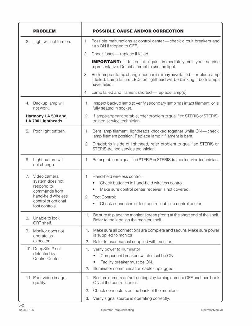
3. Light will not turn on.
1. Inspect backup lamp to verify secondary lamp has intact filament, or isfully seated in socket.
2. If lamps appear operable, refer problem to qualified STERIS or STERIS-trained service technician.
4. Backup lamp willnot work.
Harmony LA 500 andLA 700 Lightheads
1. Bent lamp filament; lightheads knocked together while ON — checklamp filament position. Replace lamp if filament is bent.
2. Dirt/debris inside of lighthead, refer problem to qualified STERIS orSTERIS-trained service technician.
5. Poor light pattern.
7. Video camerasystem does notrespond tocommands fromhand-held wirelesscontrol or optionalfoot controls.
1. Hand-held wireless control:
• Check batteries in hand-held wireless control.
• Make sure control center receiver is not covered.
2. Foot Control:
• Check connection of foot control cable to control center.
1. Refer problem to qualified STERIS or STERIS-trained service technician.6. Light pattern willnot change.
1. Possible malfunctions at control center — check circuit breakers andturn ON if tripped to OFF.
2. Check fuses — replace if failed.
IMPORTANT: If fuses fail again, immediately call your servicerepresentative. Do not attempt to use the light.
3. Both lamps in lamp change mechanism may have failed — replace lampif failed. Lamp failure LEDs on lighthead will be blinking if both lampshave failed.
4. Lamp failed and filament shorted — replace lamp(s).
8. Unable to lockCRT shelf.
9. Monitor does notoperate asexpected.
10. DeepSite™ notdetected byControl Center.
11. Poor video imagequality.
1. Be sure to place the monitor screen (front) at the short end of the shelf.Refer to the label on the monitor shelf.
1. Make sure all connections are complete and secure. Make sure poweris supplied to monitor
2. Refer to user manual supplied with monitor.
1. Verify power to illuminator
• Component breaker switch must be ON.
• Facility breaker must be ON.
2. Illuminator communication cable unplugged.
1. Restore camera default settings by turning camera OFF and then backON at the control center.
2. Check connectors on the back of the monitors.
3. Verify signal source is operating correctly.

6-1Operator Manual Maintenance 129382-106
Preventive Maintenance Schedule – Harmony® Lux Advantage LASurgical Lighting and Visualization System
Procedure Frequency Paragraph (if applicable*)
Inspect lampholder and lamps each inspection,or each lamp Inspect Lamp Change Mechanism
change
Change secondary lamp every year Lamp Replacement(Harmony LA 500 and LA 700)
Check light pattern and illumination levels every year(Harmony LA 500 and LA 700)
Inspect system and arm wiring for every 6 monthsdeterioration or loose connections
Inspect arm assembly for ease of each inspectionmovement
Verify similar forces required to raise each inspectionand lower arm
Check suspension system for drift each inspection
Check control center each inspection Check Intensity Controls
Verify suspended components move each inspection Lighthead Positioningthrough entire range of articulationwithout binding or drifting
Inspect main wedge in center mount for each inspectiondownward movement
Verify secure attachment of sterile handle each inspectionassemblies to lighthead, includingreplacement handle of camera mount.(Harmony LA 500 and LA 700)
Inspect plug buttons, fasteners, covers orother components that may attach to the each inspectioncamera or arm or system arm components
DeepSite™ spring arm articulation annual
MAINTENANCENOTE: This schedule is supplied for the customer’s reference, any actualservice must be performed by a qualified service technician.
These procedures should be performed at regular intervals as indicated. Thisfrequency is minimum and should be increased with increased light usage.
6.1 PreventiveMaintenance
Record
* When no paragraph is listed, operation should be performed by or referred to STERIS service representative (or otherqualified technician). Refer to MAINTENANCE MANUAL P764330-226.
NOTES:1. Any repairs or adjustments to lighthead and its suspension system should only be made by qualified STERIS or
STERIS-trained service personnel while referring to MAINTENANCE MANUAL P764330-226.
2. Refer to the user manual supplied by the monitor manufacturer for Preventive Maintenance procedures relatingto monitors used with the Harmony® LA Surgical Lighting and Visualization System.
6

6-2129382-106 Maintenance Operator Manual
1. The lampholder module is accessed by opening the hood on top of thelighthead. Remove the lampholder module by pressing each of the twopush-lock/push-release fasteners.
NOTES:
a. For Harmony LA 500 and LA 700 lightheads, primary and secondarylamp positions are indicated on the lampholder by letter A (primary) orB (backup) on the lampholder module.
b. The Harmony LA 700 is equipped with a lamp change mechanism.Under normal conditions this mechanism resets, placing the primarylamp in its original position when the lampholder is removed from thelighthead.
c. Harmony LA 300 lightheads are equipped with a single lamp.
2. Inspect the lamps for damage or discoloration. Be sure the filament of thelamp in the secondary position is intact. Replace if necessary.
3. Check that lamps are firmly seated in their sockets.
4. Place the lampholder module back into the lighthead, push-to-lock eachfastener, and firmly push straight down on the top latch located on theaccess hood until it locks.
6.2 InspectLampholder
Module
6.3 InspectSuspension
Start at the highest point on the suspension, and work out toward thelightheads on each suspension arm. Verify proper operation of each brakingpoint. If necessary, adjust each of the brakes in turn, with the goal ofeliminating both binding and drift in the system. Refer to MAINTENANCE MANUAL,P764330-226, if necessary.
1. Check control center operation by cycling it OFF and ON several times.
2. Cycle through command menus on display.
a. Verify proper operation of all membrane switches (buttons).
b. Verify proper display and function of all command menus.
6.4 InspectControl Center
W A R N I N G – P E R -SONAL INJURY HAZ-ARD:
• Do not attempt to re-place the lamp unlesslighthead is turned offand has cooled suffi-ciently.
• Avoid looking directlyat high-intensity light,whether at the lampor directly at thelighthead. Eye injurymay result.
CAUTION: Do not touchthe glass portion of thelamp with bare fingers.Skin oils can cause de-terioration of materialleading to possible fail-ure of the lamp.

6-3Operator Manual Maintenance 129382-106
6.5 ReattachLighthead Access
Hood
Harmony LA 500 and LA 700 lightheads – If the lighthead access hoodshould be left open and strike another lighthead (or similar obstacle), it isdesigned to break away from the lighthead (without damage to the hood).Refer to Figure 6-1. A safety tether is included to prevent the hood from falling.
Replace the hood by sliding the clip over the barrel from the side, as shownin Figure 6-1. Align clip and barrel to verify unrestricted operation when closingor opening the hood.
Figure 6-1. Reattach Lighthead Access Hood(Harmony LA 500 and LA 700 Lightheads)
Clip BarrelSlide clip over barrel from
either side, and align.
PLEASE NOTE: Safety tether is not shown in this figure.

6-4129382-106 Maintenance Operator Manual
6.6 LampReplacement:
Harmony LA 500and LA 700Lightheads
Harmony LA 500 and LA 700 lightheads are equipped with two lamps. LampA, called the primary, is always positioned at a point in the optic assembly toprovide best focus and illumination. When lamp A (primary) fails, lamp B(backup) illuminates immediately. When the system switches from lamp A tolamp B, transmission of light to the operating table is interrupted for less thanone second.
If one lamp in a Harmony LA 500 or LA 700 lighthead fails, the failure isindicated by a graphic display on the control center and by a blinking LED onthe bottom of the lighthead's base. Do not allow a lighthead to operate for anylength of time with only one functional lamp. Always replace a failed lamp atthe earliest opportunity.Important: A lampholder module is accessed from the top of the lightheadand removed. Once removed, the failed lamp is replaced with a fresh lamp.Primary and secondary lamp positions are indicated on the lampholder byletter A (primary) or B (backup) on the lampholder module.
To replace a failed lamp, follow the steps outlined in the procedure below:1. Observe the control center status screen and note which lamp has failed.
NOTE: If fixture provides no light at all, and LED on outer cover of lightheadis blinking, check control center display to see if both lamps have failed.
2. Turn OFF the lighthead at the control center, or by using the surgeon'scontrol buttons.
3. Rotate the lighthead until it is horizontal and in a comfortable position toreach the access hood on the top.
4. Twist the latch on the access hood to open.
5. Press down on the push-release/push-lock fasteners on the lampholder.Remove the lampholder module from the lighthead.
6. Find the failed lamp by matching the indicator mark on the lampholder:
• For Harmony LA 500 and LA 700 lightheads, if the control centerindicated that lamp “A” has failed, locate and remove lamp “A” from thelampholder.
• For Harmony LA 700 lightheads, the primary lamp resets when extractedfrom the lighthead. Replace the lamp in the primary (upper) position. (SeeFigure 6-2.) If the lighthead fails to provide any light, change both lamps(upper and lower positions).
NOTE: Refer to SECTION 6.6.1, RESET HARMONY LA 700 LAMPHOLDER if lampsand lampholder are not positioned as shown in Figure 6-2.
• Remove any failed lamp(s) by grasping the lamp base in one hand andthe lampholder in the other, then gently pull the lamp from the socket.
7. Grasp the new lamp by its base ( remove protective wrapper, do not touchglass) and press into the lampholder. After replacing either lamp, inspectboth lamps to verify both have intact filaments.
8. Return the lampholder to the lighthead.
• Press the lampholder firmly into the lighthead. Press down on the push-release/push-lock fasteners to lock the lampholder in place.
NOTE: If the fasteners appear to be loose, they are not locked.
• Firmly push straight down on the top latch located on the access hooduntil it locks.
WARNING – ELECTRICSHOCK HAZARD: Donot remove covers orperform service otherthan as described in thisequipment manual. Re-fer servicing to quali-fied service personnel.(Maintenance ManualP764330-226.)
WARNING – PERSONALINJURY HAZARD:
• Do not attempt to re-place the lamp unlesslighthead is turned offand has cooled suffi-ciently.
• Avoid looking directlyat high-intensity light,whether at the lamp ordirectly at thelighthead. Eye injurymay result.
CAUTION – POSSIBLEEQUIPMENT DAMAGE:Do not touch the glassportion of the lamp withbare fingers. Skin oils cancause deterioration ofmaterial leading to pos-sible failure of the lamp.
(More)

6-5Operator Manual Maintenance 129382-106
Figure 6-2. Lamp Replacement Procedure – Harmony LA 500 Lighthead
Oncereleased,removelampholderfromlighthead.
9. Turn the lighthead ON.
10. Verify that control center and lighthead lamp failure LED have changed tolamp-ready status. If control center, or lighthead LED, continue to indicatea failed lamp, remove lampholder again and examine filament of lampindicated by control center. Verify that lamp was not damaged duringreplacement procedure. An incorrectly seated lamp also indicates afailure.
Harmony LA 700 – Removelamp in upper position (alsodesignated A on control centerdisplay). Observe handlingprecautions when removing orreplacing lamps.
Press and releasefasteners to releaselampholder.
Fastener inreleasedposition.
Twist open catchclockwise on hinged top-access hood. Open top-access hood.
Harmony LA 500 – Remove lampmatching letter designation (A or B)shown on control center display. Observehandling precautions when removing orreplacing lamps.

6-6129382-106 Maintenance Operator Manual
Figure 6-3. Reset Harmony LA 700 Lampholder Lamp Position
Lamp B in Upper Position Steady Lampholder with one hand, and press A positionlamp into upper position.
Lamp A in Upper Position
6.6.1 Reset HarmonyLA 700 Lampholder
If lamp B is in the upper position when the lampholder is removed from thelighthead (see left-hand image in Figure 6-3), the lampholder must be resetbefore returning it to the lighthead.
1. Place the lampholder on a flat surface and firmly support the lampholderbase with one hand.
2. Press firmly on the “A” position side of the lampholder, as shown in thecenter image of Figure 6-3.
3. The lampholder should reset with a definite and positive motion to theposition shown in the right-hand image shown in Figure 6-3.
4. Replace the lamp as necessary following the instruction in the Section 6.6,Lamp Replacement: Harmony LA 500 and LA 700 Lightheads and returnthe lampholder to the lighthead.

6-7Operator Manual Maintenance 129382-106
Harmony LA 300 lightheads are equipped with a single lamp.
If the lamp in a Harmony LA 300 lighthead fails, the failure is indicated by agraphic display on the control center; also — the lighthead provides no light.Always replace a failed lamp at the earliest opportunity.
Important: The lampholder module is accessed from the top of the lightheadand removed. Once removed, the failed lamp is replaced with a fresh lamp.
Refer to Figure 6-4.
To replace a failed lamp, follow the steps outlined in the procedure below:
1. Observe the control center status screen, or look at the Harmony LA 300lightheads in the system, and note which lamp has failed.
2. Turn OFF the lighthead at the control center, or by using the surgeon'scontrol buttons.
3. Rotate the lighthead until it is horizontal and in a comfortable position toreach the access hood on the top.
4. Slide the latch on the access hood, and lift to open.
5. Press down on the push-release/push-lock fasteners on the lampholder.Remove the lampholder module from the lighthead.
6. Remove the failed lamp by grasping the lamp base in one hand and thelampholder in the other, then gently pull the lamp from the socket.
7. Grasp the new lamp by its base (remove protective wrapper, do not touchglass) and press into the lampholder. After replacing lamp, inspect it toverify it has an intact filament.
8. Return the lampholder to the lighthead.• Press the lampholder firmly into the lighthead. Press down on the push-
release/push-lock fasteners to lock the lampholder in place.
NOTE: If the fasteners appear to be loose, they are not locked.
• Firmly push straight down on the access hood until it locks. Slide the latchfully into the closed position, if necessary.
9. Turn the lighthead ON.
10. Verify that the control center has changed to lamp-ready status. If thecontrol center continues to indicate a failed lamp, remove lampholderagain and examine the filament of the lamp indicated by the control centerto verify that it was not damaged during the lamp replacementprocedure. An incorrectly seated lamp also indicates a failure.
6.7 LampReplacement:
Harmony LA 300Lightheads
WARNING – ELECTRICSHOCK HAZARD: Donot remove covers orperform service otherthan as described in thisequipment manual. Re-fer servicing to quali-fied service personnel.(Maintenance ManualP764330-226.)
WARNING – PERSONALINJURY HAZARD:
• Do not attempt to re-place the lamp unlesslighthead is turned offand has cooled suffi-ciently.
• Avoid looking directlyat high-intensity light,whether at the lamp ordirectly at thelighthead. Eye injurymay result.
CAUTION – POSSIBLEEQUIPMENT DAMAGE:Do not touch the glassportion of the lamp withbare fingers. Skin oils cancause deterioration ofmaterial leading to pos-sible failure of the lamp.

6-8129382-106 Maintenance Operator Manual
Harmony LA 300 lampholder requires asingle replacement lamp.
NOTE: Harmony LA300 lighthead isequipped with a slidingcatch on the top hood.
Open catch on hingedtop-access hood. Opentop-access hood.
Press and releasefasteners to releaselampholder.
Fastener inreleasedposition.
Figure 6-4. Lamp Replacement Procedure – Harmony LA 300 Lighthead

6-9Operator Manual Maintenance 129382-106
6.8 LampReplacement:
Optional DeepSiteLighthead
The Harmony LA Control Center provides a DeepSite lamp-life indicatordisplay (see Figure 6-5). When the control center indicates the lamp hasreached the end of its usable life, change the lamp immediately.
Refer to Figure 6-6.
Important: The DeepSite™ lamp must be turned OFF at the control centerbefore attempting to change the lamp.
1. Place a stable ladder beneath the ceiling illuminator.
2. Ascend the ladder, grasp the lamp release lever on the lamp housing andmove lever to the "open" position. (See Figure 6-6.)
3. The lamp housing is equipped with a movement dampening mechanism.Allow the lamp housing to drop to its lowest position. (See Figure 6-6.)
NOTE: A slight pull downward may be required to start the housing in motion.
4. The lamp should only be handled using its heat-insulated handle (SeeFigure 6-7). Assuring that the lamp is cool enough to handle, unscrew it fromthe housing.
5. Replace the spent lamp with a new one by inserting the lamp module intothe threaded recess of the housing (See Figure 6-7).
• Rotate the lamp clockwise (threading inward) until it is hand tight.
NOTE: The internal pressure of a spent lamp may be relieved by openingthe pinched-off tabulation located on the back of the lamp. This may beaccomplished by inserting a standard screwdriver into the slot providedthrough the side of the lamp assembly (see Figure 6-7). Tap on thescrewdriver handle to break off the small tip inside the slot. Once this hasbeen done, the old lamp may be discarded with normal trash. If the internalgas pressure is not relieved, care should be taken that the lamp is notincinerated but goes to a landfill. There is a very small percentage of thoriumoxide in the Cermax lamp cathode. Thorium is radioactive. However, theamount of thorium is so minute that it is not a hazard and the lamp can belegally disposed of without concern about radioactivity.
6. Raise the lamp housing into the ceiling illuminator and move the lamprelease lever to the "lock" position.
7. Verify that the New Lamp LED on the lamp-life indicator is lit once the controlcenter is turned on. The lamp-life indicator automatically resets to NewLamp after the lamp housing lever is opened for 25 seconds and the circuitbreaker is ON.
W A R N I N G – P E R -SONAL INJURY HAZ-ARD: Do not attempt toreplace lamp unlessthe power is turned offat the control centerand the lamp modulehas cooled sufficiently.Lamp contains xenongas at high pressure.Persons changing ordisposing of the lampshould wear eye pro-tection.
WARNING – EXPLO-SION AND LACERA-TION HAZARD: Thislamp contains xenongas at high pressure.Proper disposal proce-dures must be followed.Use eye protectionwhen working withthese lamps.
Figure 6-5. DeepSite Lamp-Life Indicator Display
DeepSite Intensity StatusIndicator
DeepSite Lamp LifeStatus Indicator
New Lamp Spent Lamp
Approximate Lamp LifeUsed/Remaining
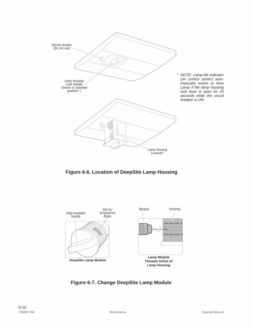
6-10129382-106 Maintenance Operator Manual
Figure 6-7. Change DeepSite Lamp Module
Figure 6-6. Location of DeepSite Lamp Housing
Lamp ModuleThreads In/Out of
Lamp Housing
Module Housing
DeepSite Lamp Module
Heat-insulatedHandle
Service Access(Do not use)
Lamp HousingLock Handle
(shown in unlockedposition*)
Lamp HousingLowered*
Slot forScrewdriver
Blade
* NOTE: Lamp-life indicator(on control center) auto-matically resets to NewLamp if the lamp housinglock lever is open for 25seconds while the circuitbreaker is ON.

7-1Operator Manual Replacement Parts 129382-106
7
Parts listed in this section are those that would be necessary to do minormaintenance on the lighting fixture. Quantities listed are the minimum numberof spares that we recommend you keep on hand.
When ordering, please include the part number, description, and quantity foreach replacement part requested.
To order directly, call STERIS; or visit https://eservice.steris.com.
REPLACEMENT PARTS
Harmony® Lux Advantage LA 500/700 ................................................................................ P093926-047
Replacement Lamp ....................................................................................................................... (LB11)
Harmony Lux Advantage LA 300 Replacement Lamp ......................................................... P093926-113
Replacement Lamp ....................................................................................................................... (LB21)
DeepSite™ Replacement Lamp .......................................................................................... P136818-113
Harmony LA 500 Lamp Change Assembly ......................................................................... P146667-095
Harmony LA 700 Lamp Change Assembly ......................................................................... P146667-015
Harmony LA 500 Lighthead (Complete ) ............................................................................. P129382-391
Harmony LA 700 Lighthead (Complete ) ............................................................................. P129382-393
Cover, Lamp Change, LA 500 ............................................................................................. P136820-084
Cover, Lamp Change, LA 700 ............................................................................................. P146667-115
Harmony LA Maintenance Manual ....................................................................................... P764330-226
Plastic Lighthandle ........................................................................................................................ (LB20)
Light Handle Sterile Cover (Current Design) .................................................................................. (LB42)
Camera Handle Sterile Cover ........................................................................................................ (LB47)
Monitor Sterile Cover (Single) ........................................................................................................ (LB45)
Monitor Sterile Cover (Dual) ........................................................................................................... (LB46)
Lighthandle Sterile Cover (Dual, Previous Design) ........................................................................ (LB40)
Sterile Disposable Cover for Optional Monitor Handle ............................................... (LB70-single pack)(LB71-dual pack)
DeepSite Sterile Sheath ....................................................................................................... P136818-103
Brake Screw, DeepSite ...................................................................................................... P000372-44D
Brake Screw, Lighthead Spring Arm .................................................................................. P000661-69D
Brake Screw, Light, Main Suspension System ................................................................... P000358-99D
Single Use LOCTITE®1 242 .................................................................................................. P129377-290
Description Part Number
. . . Continued
1. LOCTITE® is a registered trademark of Henkel Technologies.

7-2129382-106 Replacement Parts Operator Manual
Sterile Cover for Lighthandle (Dual) .......................................................................... (LB41-single pack)
Video Cable, DVI (via HDMI) (Length = 1.8 m [72 in] - 2m [79 in]) ...................................... P129382-761
Video Cable, S-Video (via 2 BNC) (Length = 1.8 m [72 in] - 2m [79 in]) ..............................P129382-759
Video Cable, SDI/Composite (BNC-BNC) (Length = 1.8 m [72 in] - 2m [79 in]) ...................P129382-760
Video Cable, VGA (HD15) (Length = 1.8 m [72 in] - 2m [79 in]) ......................................... P093926-506
SDI Modem .........................................................................................................................P136820-493
DVI Modem .........................................................................................................................P136820-492
VGA Modem ....................................................................................................................... P136820-495
S-Video Modem ..................................................................................................................P136820-494
Description Part Number

8-1Operator Manual Waste Disposal Guidelines 129382-106
WASTE DISPOSAL GUIDELINES
WARNING – EXPLOSIONAND LACERATION HAZ-ARD: This lamp containsxenon gas at high pres-sure. Proper disposalprocedures must be fol-lowed. Use eye protec-tion when working withthese lamps.
WARNING–DISPOSALHAZARD: This productcontains materials whichmay require disposalthrough appropriately li-censed and permittedhazardous waste man-agement firms.
The following materials are contained within the Harmony® Lux Advantage LALighting System. When disposing of the lighting fixture or its parts, ensureproper disposal of hazardous and other regulated waste in compliance withnational, state, and local regulations.
Lead (Pb) in Solder - contained in solder on circuit boards and in somemiscellaneous wire connections. Minute amounts.
Electronic and Electrical Parts - not known to require special disposalmethods at date of this manual.
Metal Parts - made from aluminum (Al), steel (Fe), cast iron (Fe), copper (Cu),and copper alloys (Cu/x), plastic, synthetic rubber, plating (Cr, Ni, Zn, Au),and adhesives not known to require special disposal methods at date of thismanual.
DeepSite™ Lamp Module - contains xenon gas under pressure.
NOTE: The internal pressure of a spent lamp may be relieved by opening thepinched-off tabulation located on the back of the lamp. This may be accom-plished by inserting a standard screwdriver into the slot provided through theside of the lamp assembly (see Figure 8-1). Tap on the screwdriver handle tobreak off the small tip inside the slot. Once this has been done, the old lamp maybe discarded with normal trash. If the internal gas pressure is not relieved, careshould be taken that the lamp is not incinerated but goes to a landfill. There isa very small percentage of thorium oxide in the Cermax lamp cathode. Thoriumis radioactive. However, the amount of thorium is so minute that it is not ahazard and the lamp can be legally disposed of without concern aboutradioactivity.
8
Figure 8-1. Change DeepSite Lamp Module
DeepSite Lamp Module
Heat-insulatedHandle
Slot forScrewdriver
Blade

9-1Appendix - EMC Compliance Technical Data Operator Manual 129382-106
APPENDIX – EMC Compliance Technical Data
Guidance and Manufacturer’s Declaration – Electromagnetic Emissions for allEquipment and Systems
Guidance and Manufacturer’s Declaration – Electromagnetic Emissions – for all Equipment and Systems(per IEC 60601-2 clause 6.8.3.201 a – 3 Table 201a)
The Harmony® LA Surgical Lighting System without video monitor and video monitor-related components isintended for use in the electromagnetic environment specified below. The customer or the user of the Harmony LA
System should assure that it is used in such an environment.
Emissions test Compliance Electromagnetic environment – guidance
RF emissions CISPR 11 Group 1 The Harmony LA System uses RF energy only for itsinternal function. Therefore, its RF emissions are verylow and are not likely to cause any interference innearby electronic equipment.
RF emissions CISPR 11 Class B The Harmony LA System is suitable for use in allestablishments, including domestic establishments
Harmonic emissions Class C and those directly connected to the public low-IEC 61000-3-2 voltage power supply network that supplies buildings
used for domestic purposes.Voltage fluctuations/flicker Compliesemissions IEC 61000-3-3
9
Guidance and Manufacturer’s Declaration – Electromagnetic Emissions for allEquipment and Systems
Guidance and Manufacturer’s Declaration – Electromagnetic Emissions – for all Equipment and Systems(per IEC 60601-2 clause 6.8.3.201 a – 3 Table 201b)
The Harmony® LA Surgical Lighting System with video monitor and video monitor-related components is intendedfor use in the electromagnetic environment specified below. The customer or the user of the Harmony LA System
should assure that it is used in such an environment.
Emissions test Compliance Electromagnetic environment – guidance
RF emissions CISPR 11 Group 1 The Harmony LA System uses RF energy only for itsinternal function. Therefore, its RF emissions are verylow and are not likely to cause any interference innearby electronic equipment.
RF emissions CISPR 11 Class A The Harmony LA System is suitable for use in allestablishments other than domestic and those directly
Harmonic emissions Class C connected to the public low-voltage power supplyIEC 61000-3-2 network that supplies buildings used for domestic
purposes.Voltage fluctuations/flicker Compliesemissions IEC 61000-3-3

9-2129382-106 Operator Manual Appendix - EMC Compliance Technical Data
Guidance and Manufacturer’s Declaration – Electromagnetic Immunity – for all Equipment and Systems (perIEC 60601-2 clause 6.8.3.201 a – 6 Table 202)Guidance and Manufacturer’s Declaration –
Electromagnetic Immunity for all Equipment and Systems
The Harmony LA Surgical Lighting System is intended for use in the electromagnetic environment specified below.The customer or the user of the Harmony LA System should assure that it is used in such an environment.
Immunity test IEC 60601 Test Level Compliance Level Electromagnetic Environment –Guidance
Electrostatic discharge (ESD) ±6 kV contact ±6 kV contact Floors should be wood, concrete orIEC 61000-4-2 ±8 kV air ±8 kV air ceramic tile. If floors are covered with
synthetic material, the relative humidityshould be at least 30 %.
Electrical fast transient/burst ±2 kV for ±2 kV for Mains power quality should be thatIEC 61000-4-4 power supply lines power supply lines of a typical commercial or hospital envi-
ronment.±1 kV for ±1 kV for
input/output lines input/output lines
Surge ±1 kV differential ±1 kV differential Mains power quality should be that of aIEC 61000-4-5 mode mode typical commercial or hospital envi
-ronment.±2 kV common mode ±2 kV common mode
Voltage dips, short interruptions <5 % UT <5 % UT Mains power quality should be that of aand voltage variations on power (>95 % dip in UT) (>95 % dip in UT) typical commercial or hospital envi-supply input lines for 0,5 cycle for 0,5 cycle ronment. If the user of the Harmony LA
System requires continued operationIEC 61000-4-11 40 % UT 40 % UT during power mains interruptions, it is
(60 % dip in UT) (60 % dip in UT) recommended that the Harmony LAfor 5 cycles for 5 cycles System be powered from an uninter-
ruptible power supply or a battery.70 % UT 70 % UT
(30 % dip in UT) (30 % dip in UT) (Tested at UT = to 240Vac andfor 25 cycles for 25 cycles UT= 100Vac, 50Hz for each all test
levels).<5 % UT <5 % UT
(>95 % dip in UT) (>95 % dip in UT)for 5 sec for 5 sec
Power frequency (50/60 Hz) 3 A/m 3 A/m Power frequency magnetic fieldsmagnetic field should be at levels characteristic of aIEC 61000-4-8 typical location in a typical commercial
or hospital environment.
NOTE: UT is the ac mains voltage prior to application of the test level.

9-3Appendix - EMC Compliance Technical Data Operator Manual 129382-106
Guidance and Manufacturer’s Declaration – Electromagnetic Immunity – for Equipment and Systems that arenot Life-Supporting (per IEC 60601-2 clause 6.8.3.201 b Table 204)
Guidance and Manufacturer’s Declaration – Electromagnetic Immunity for Equipment and Systems that arenot Life-Supporting
The Harmony LA Surgical Lighting System is intended for use in the electromagnetic environment specified below.The customer or the user of the Harmony LA System should assure that it is used in such an environment.
Immunity test IEC 60601 Compliance Electromagnetic Environment–Test Level Level Guidance
Portable and mobile RF communicationsequipment should be used no closer to anypart of the Harmony LA System, includingcables, than the recommended separationdistance calculated from the equationapplicable to the frequency of thetransmitter.Recommended separation distance:
Conducted RF 3 Vrms 3 Vrms PPd 2.1]35.3
[
IEC 61000-4-6 150 kHz to 80 MHz PPd 2.1]35.3
[ , 80 MHz to 800 MHz
Radiated RF 3 V/m 3 V/m PPd 3.2]3
7[ , 800 MHz to 2.5 GHz
IEC 61000-4-3 80 MHz to 2.5 GHz
where P is the maximum output power rating of thetransmitter in watts (W) according to the transmittermanufacturer and d is the recommendedseparation distance in metres (m).
Field strengths from fixed RF transmitters, asdetermined by an electromagnetic site survey,a
should be less than the compliance level in eachfrequency range.b Interference may occur in thevicinity of equipment marked with the followingsymbol:
NOTE1: At 80 MHz and 800 MHz, the higher frequency range applies.
NOTE2: These guidelines may not apply in all situations. Electromagnetic propagation is affected by absorption andreflection from structures, objects and people.
a: Field strengths from fixed transmitters, such as base stations for radio (cellular/ cordless) telephones and land mobile radios,amateur radio, AM and FM radio broadcast and TV broadcast cannot be predicted theoretically with accuracy. To assess theelectromagnetic environment due to fixed RF transmitters, an electromagnetic site survey should be considered. If the measured fieldstrength in the location in which the Harmony LA System is used exceeds the applicable RF compliance level above, the Harmony LASystem should be observed to verify normal operation. If abnormal performance is observed, additional measures may be necessary,such as reorienting or relocating the Harmony LA System.b: Over the frequency range 150 kHz to 80 MHz, field strengths should be less than 3 V/m.

9-4129382-106 Operator Manual Appendix - EMC Compliance Technical Data
Recommended Separation Distances Between Portable and Mobile RF Communications Equipment and theEquipment or System – For Equipment and Systems that are not Life-Supporting (per IEC 60601- 2, 6.8.3.201
b Table 206)Recommended Separation Distances Between Portable and Mobile RF communications
Equipment and the Harmony LA System
The Harmony LA Surgical Lighting System is intended for use in an electromagnetic environment in which radiatedRF disturbances are controlled. The customer or the user of the Harmony LA System can help preventelectromagnetic interference by maintaining a minimum distance between portable and mobile RF communicationsequipment (transmitters) and the Harmony LA System as recommended below, according to the maximum outputpower of the communications equipment.
Rated maximum output Separation distance according to frequency of transmitterpower of transmitter m
W 150 kHz to 80 MHz 80 MHz to 800 MHz 800 MHz to 2.5 GHz
Pd ]35.3
[ Pd ]35.3
[ Pd ]3
7[
0,01 0.12 0.12 0.23
0,1 0.38 0.38 0.73
1 1.2 1.2 2.3
10 3.8 3.8 7.3
100 12 12 23
For transmitters rated at a maximum output power not listed above, the recommended separation distance d inmetres (m) can be estimated using the equation applicable to the frequency of the transmitter, where P is themaximum output power rating of the transmitter in watts (W) according to the transmitter manufacturer.
NOTE 1: At 80 MHz and 800 MHz, the separation distance for the higher frequency range applies.
NOTE 2: These guidelines may not apply in all situations. Electromagnetic propagation is affected by absorption andreflection from structures, objects and people.