operator manual & parts catalog - degelman 7000.pdf · strawmaster 7000 30’, 50’, 62’,...
TRANSCRIPT
STRAWMASTER 700030’, 50’, 62’, 70’ & 82’
Serial Numbers up to 7139
OPERATOR MANUAL & PARTS CATALOG
142628 v1.6
D E G E L M A N I N D U S T R I E S L T D.B O X 8 3 0 - 2 7 2 I N D U S T R I A L D R I V E ,R E G I N A , S K , C A N A D A , S 4 P 3 B 1FA X 306.543.2140 P H 3 0 6 . 5 4 3 . 4 4 4 71 . 8 0 0 . 6 6 7 . 3 5 4 5 D E G E L M A N . C O M

D E G E L M A N I N D U S T R I E S L T D.B O X 8 3 0 - 2 7 2 I N D U S T R I A L D R I V E ,R E G I N A , S K , C A N A D A , S 4 P 3 B 1FA X 306.543.2140 P H 3 0 6 . 5 4 3 . 4 4 4 71 . 8 0 0 . 6 6 7 . 3 5 4 5 D E G E L M A N . C O M
IMPORTANT:
READ MANUAL
TABLE OF CONTENTS - OPERATORS SECTION
Introduction 1
Safety Safety Information 2
Operation Overview / Preparation 6
Hook-Up 8
Convert to Field Position 9
Suggested Tine Angle Settings 10
Height Adjustment 11
Transporting / Storage 12
Service & Maintenance Service 13
Repair 15
Troubleshooting 19
TABLE OF CONTENTS - PARTS SECTION 21
Warranty 44

-1-142628 - Strawmaster 7000 (27-September-2013)
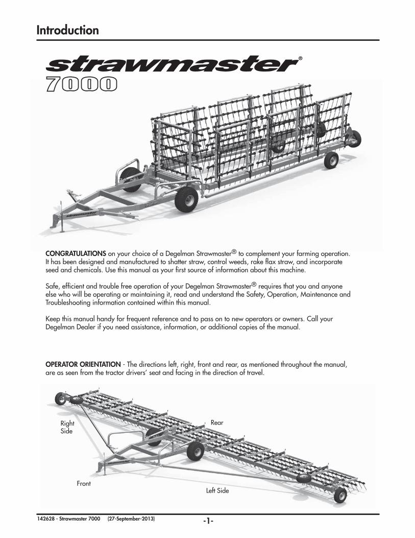
OPERATOR ORIENTATION - The directions left, right, front and rear, as mentioned throughout the manual, are as seen from the tractor drivers’ seat and facing in the direction of travel.
Introduction
Left Side
Rear
Front
Right Side
CONGRATULATIONS on your choice of a Degelman Strawmaster® to complement your farming operation. It has been designed and manufactured to shatter straw, control weeds, rake flax straw, and incorporate seed and chemicals. Use this manual as your first source of information about this machine.
Safe, efficient and trouble free operation of your Degelman Strawmaster® requires that you and anyone else who will be operating or maintaining it, read and understand the Safety, Operation, Maintenance and Troubleshooting information contained within this manual.
Keep this manual handy for frequent reference and to pass on to new operators or owners. Call your Degelman Dealer if you need assistance, information, or additional copies of the manual.

-2-142628 - Strawmaster 7000 (27-September-2013)
The Safety Alert Symbol identifies important safety messages applied to the Strawmaster® and in this manual. When you see this symbol, be alert to the possibility of injury or death. Follow the instructions provided on the safety messages.
The Safety Alert Symbol means:
ATTENTION! BECOME ALERT!
YOUR SAFETY IS INVOLVED!
DANGER: Indicates an imminently hazardous situation that, if not avoided, WILL result in death or serious injury if proper precautions are not taken.
WARNING: Indicates a potentially hazardous situation that, if not avoided, COULD result in death or serious injury if proper precautions are not taken.
CAUTION: Indicates a potentially hazardous situation that, if not avoided, MAY result in minor or moderate injury if proper practices are not taken, or, serves as a reminder to follow appropriate safety practices.
Why is SAFETY important to YOU?
3 BIG Reasons:
•AccidentsCanDisableandKill •AccidentsAreCostly •AccidentsCanBeAvoided
Note the use of the Signal Words: DANGER, WARNING, and CAUTION with the safety messages. The appropriate Signal Word has been selected using the following guidelines:
SAFETY ALERT SYMBOL
SIGNAL WORDS
Safety
CAUTION
DANGER
WARNING

-3-142628 - Strawmaster 7000 (27-September-2013)
1. Read and understand the Operator’s Manual and all safety signs before operating, maintaining or adjusting the Strawmaster®.
2. Install and properly secure all shields and guards before operating. Use hitch pin with a mechanical locking device.
3. Have a first-aid kit available for use should the need arise and know how to use it.
4. Have a fire extinguisher available for use should the need arise and know how to use it.
5. Wear appropriate protective gear. This list includes but is not limited to:
• A hard hat• Protective shoes with slip resistant soles• Protective glasses or goggles• Heavy gloves• Wet weather gear• Hearing protection• Respirator or filter mask
6. Clear the area of people, especially small children, and remove foreign objects from the machine before starting and operating.
7. Do not allow riders.
8. Stop tractor engine, set park brake, remove ignition key and wait for all moving parts to stop before servicing, adjusting, repairing or unplugging.
9. Review safety related items with all operators annually.
YOU are responsible for the safe operation andmaintenance of your Degelman Strawmaster®. YOU must ensure that you and anyone else who is going to operate, maintain or work around the Strawmaster® be familiar with the operating and maintenance procedures and related SAFETY information contained in this manual.This manual will take you step-by-step through your working day and alerts you to all good safety practices that should be adhered to while operating this equipment.
Remember, YOU are the key to safety. Good safety practices not only protect you but also the people around you. Make these practices a working part of your safety program. Be certain that EVERYONE operating this equipment is familiar with the recommended operating and maintenance procedures and follows all the safety precautions. Most accidents can be prevented. Do not risk injury or death by ignoring good safety practices.
• Strawmaster® owners must give operating instructions to operators or employees before allowing them to operate the Strawmaster®, and at least annually thereafter per OSHA regulation 1928.51.
• The most important safety device on this equipment is a SAFE operator. It is the opera-tor’s responsibility to read and understand ALL Safety and Operating instructions in the manual and to follow these. All accidents can be avoided.
• A person who has not read and under-stood all operating and safety instructions is not qualified to operate the machine. An untrained operator exposes himself and by-standers to possible serious injury or death.
• Do not modify the equipment in any way. Unauthorized modification may impair the function and/or safety and could affect the life of the equipment.
• Think SAFETY! Work SAFELY!
Safety
SAFETY GENERAL SAFETY
-4-142628 - Strawmaster 7000 (27-September-2013)
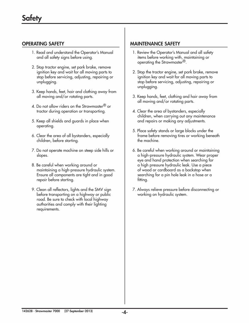
1. Review the Operator’s Manual and all safety items before working with, maintaining or operating the Strawmaster®.
2. Stop the tractor engine, set park brake, remove ignition key and wait for all moving parts to stop before servicing, adjusting, repairing or unplugging.
3. Keep hands, feet, clothing and hair away from all moving and/or rotating parts.
4. Clear the area of bystanders, especially children, when carrying out any maintenance and repairs or making any adjustments.
5. Place safety stands or large blocks under the frame before removing tires or working beneath the machine.
6. Be careful when working around or maintaining a high-pressure hydraulic system. Wear proper eye and hand protection when searching for a high pressure hydraulic leak. Use a piece of wood or cardboard as a backstop when searching for a pin hole leak in a hose or a fitting.
7. Always relieve pressure before disconnecting or working on hydraulic system.
1. Read and understand the Operator’s Manual and all safety signs before using.
2. Stop tractor engine, set park brake, remove ignition key and wait for all moving parts to stop before servicing, adjusting, repairing or unplugging.
3. Keep hands, feet, hair and clothing away from all moving and/or rotating parts.
4. Do not allow riders on the Strawmaster® or tractor during operation or transporting.
5. Keep all shields and guards in place when operating.
6. Clear the area of all bystanders, especially children, before starting.
7. Do not operate machine on steep side hills or slopes.
8. Be careful when working around or maintaining a high-pressure hydraulic system. Ensure all components are tight and in good repair before starting.
9. Clean all reflectors, lights and the SMV sign before transporting on a highway or public road. Be sure to check with local highway authorities and comply with their lighting requirements.
Safety
OPERATING SAFETY MAINTENANCE SAFETY

-5-142628 - Strawmaster 7000 (27-September-2013)
1. Always place all tractor hydraulic controls in neutral before dismounting.
2. Make sure that all components in the hydraulic system are kept in good condition and are clean.
3. Replace any worn, cut, abraded, flattened or crimped hoses and metal lines.
4. Do not attempt any makeshift repairs to the hydraulic lines, fittings or hoses by using tape, clamps or cements. The hydraulic system operates under extremely high-pressure. Such repairs will fail suddenly and create a hazardous and unsafe condition.
5. Wear proper hand and eye protection when searching for a high-pressure hydraulic leak. Use a piece of wood or cardboard as a backstop instead of hands to isolate and identify a leak.
6. If injured by a concentrated high-pressure stream of hydraulic fluid, seek medical attention immediately. Serious infection or toxic reaction can develop from hydraulic fluid piercing the skin surface.
7. Before applying pressure to the system, make sure all components are tight and that lines, hoses and couplings are not damaged.
• Think SAFETY! Work SAFELY
1. Read and understand ALL the information in the Operator’s Manual regarding procedures and SAFETY when operating the Strawmaster® in the field/yard or on the road.
2. Check with local authorities regarding machine transport on public roads. Obey all applicable laws and regulations.
3. Always travel at a safe speed. Use caution when making corners or meeting traffic.
4. Make sure the SMV (Slow Moving Vehicle) emblem and all the lights and reflectors that are required by the local highway and transport authorities are in place, are clean and can be seen clearly by all overtaking and oncoming traffic.
5. Keep to the right and yield the right-of-way to allow faster traffic to pass. Drive on the road shoulder, if permitted by law.
6. Always use hazard warning flashers on tractor when transporting unless prohibited by law.
7. Always use a pin with provisions for a mechanical retainer and a safety chain when attaching to a tractor or towing vehicle.
1. Failure to follow proper procedures when mounting a tire on a wheel or rim can produce a blow out which may result in serious injury or death.
2. Do not attempt to mount a tire unless you have the proper equipment and experience to do the job.
3. Have a qualified tire dealer or repair serviceman perform required tire maintenance.
Safety
HYDRAULIC SAFETY TRANSPORT SAFETY
TIRE SAFETY
-6-142628 - Strawmaster 7000 (27-September-2013)
1
3
4
5
6
7
2
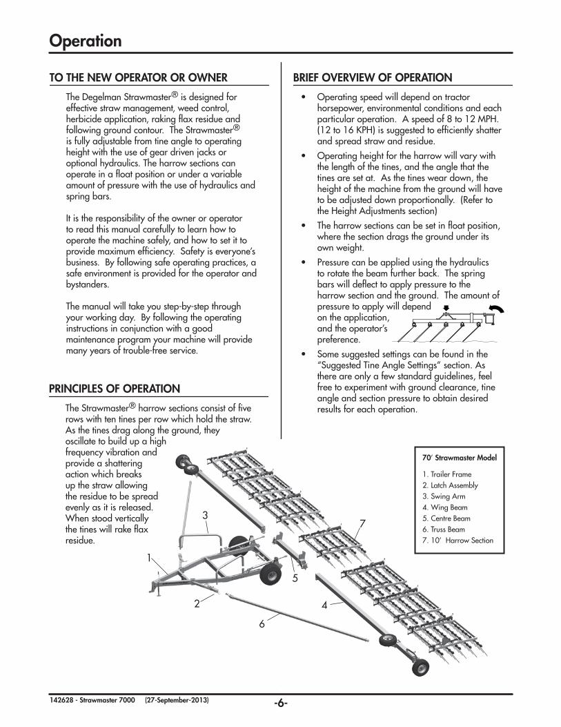
70’ Strawmaster Model
1. Trailer Frame2. Latch Assembly3. Swing Arm4. Wing Beam5. Centre Beam6. Truss Beam7. 10’ Harrow Section
Operation
The Degelman Strawmaster® is designed for effective straw management, weed control, herbicide application, raking flax residue and following ground contour. The Strawmaster® is fully adjustable from tine angle to operating height with the use of gear driven jacks or optional hydraulics. The harrow sections can operate in a float position or under a variable amount of pressure with the use of hydraulics and spring bars.
It is the responsibility of the owner or operator to read this manual carefully to learn how to operate the machine safely, and how to set it to provide maximum efficiency. Safety is everyone’s business. By following safe operating practices, a safe environment is provided for the operator and bystanders.
The manual will take you step-by-step through your working day. By following the operating instructions in conjunction with a good maintenance program your machine will provide many years of trouble-free service.
TO THE NEW OPERATOR OR OWNER
The Strawmaster® harrow sections consist of five rows with ten tines per row which hold the straw. As the tines drag along the ground, they oscillate to build up a high frequency vibration and provide a shattering action which breaks up the straw allowing the residue to be spread evenly as it is released. When stood vertically the tines will rake flax residue.
PRINCIPLES OF OPERATION
BRIEF OVERVIEW OF OPERATION
• Operating speed will depend on tractor horsepower, environmental conditions and each particular operation. A speed of 8 to 12 MPH. (12 to 16 KPH) is suggested to efficiently shatter and spread straw and residue.
• Operating height for the harrow will vary with the length of the tines, and the angle that the tines are set at. As the tines wear down, the height of the machine from the ground will have to be adjusted down proportionally. (Refer to the Height Adjustments section)
• The harrow sections can be set in float position, where the section drags the ground under its own weight.
• Pressure can be applied using the hydraulics to rotate the beam further back. The spring bars will deflect to apply pressure to the harrow section and the ground. The amount of pressure to apply will depend on the application, and the operator’s preference.
• Some suggested settings can be found in the “Suggested Tine Angle Settings” section. As there are only a few standard guidelines, feel free to experiment with ground clearance, tine angle and section pressure to obtain desired results for each operation.

-7-142628 - Strawmaster 7000 (27-September-2013)
Operation
Although there are no operational restrictions on the Strawmaster® when it is new, there are some mechanical checks that must be done to ensure the long term integrity of the unit. When using the machine for the first time, follow this procedure:
IMPORTANT: It is extremely important to followall of the Break-In procedures especially those listed in the “Before using” section below to avoid damage:
A. Before using:
1. Read Safety Info. & Operator’s Manual. 2. Complete steps in “Pre-Operation Checklist”. 3. Lubricate all grease points. 4. Check all bolt tightness. B. After operating for 2 hours:
1. Check all hardware. Tighten as required. 2. Check all hydraulic system connections. Tighten if any are leaking.
C. After operating for 8 hours:
1. Repeat Step B. 2. Re-torque all bolts on harrow sections and mounting brackets. 3. Go to the service schedule as outlined in the “Service & Maintenance” section.
BREAK-IN
Before operating the machine and each time there-after, the following areas should be checked off:
1. Lubricate the machine per the schedule outlined in the “Service & Maintenance Section”.
2. Use only a tractor with adequate power to pull the Strawmaster® under ordinary operating conditions:
Minimum Ideal
30’ model: 100 HP 150 HP 50’ model: 150 HP 200 HP 62’ model: 175 HP 250 HP 70’ model: 200 HP 300 HP 82’ model: 300 HP 350 HP
3. Ensure the Hitch Clevis is set at the correct height for the tractor drawbar and trailer height. (Refer to the “Height Adjustment” section for settings)
4. Ensure that the machine is properly attached to the tractor using a drawbar pin with provisions for a mechanical retainer. Make sure that a retainer such as a Klik pin is installed.
NOTE: It is important to pin the draw bar in the central location only.
5. Check tires and ensure that they are inflated to the specified pressure. (refer to page 13)
6. Ensure that a safety chain on the hitch is installed.
7. Check oil level in the tractor hydraulic reservoir. Top up as required.
8. Inspect all hydraulic lines, hoses, fittings and couplers for tightness. Tighten if there are leaks. Use a clean cloth to wipe any accumulated dirt from the couplers before connecting to the tractor’s hydraulic system.
9. Check all the machine settings, refer to the Adjustment section. Perform adjustments as necessary.
10. Check tines, remove entangled debris. Replace damaged tines. If tines are 16 in. or less in length, they should be replaced. (New tine length: 26 in.) See section on Tine Replacement.
PRE-OPERATIONCHECKLIST
It is important for both personal safety and maintaining the good mechanical condition of the machine that this pre-operational checklist be followed.
OPERATING SAFETY
• Read and understand the Operator’s Manual before starting.
• Lower to ground, stop engine, place all controls in neutral, set park brake and remove ignition key before servicing, adjusting or repairing.
• Keep hands, feet, hair and clothing away from all moving and/or rotating parts.
• Do not allow riders.
• Clear the area of bystanders, especially small children.
• Stay well back from machine when operating. Keep others away.

-8-142628 - Strawmaster 7000 (27-September-2013)
The Strawmaster® should always be parked on a level, dry area that is free of debris and foreign objects. Follow this procedure to hook-up:
1. Clear the area of bystanders and remove foreign objects from the machine and working area.
2. Make sure there is enough room to back the tractor up to the trailer hitch.
3. Start the tractor and slowly back it up to the hitch point.
4. Stop the tractor engine, place all controls in neutral, set park brake and remove ignition key before dismounting.
5. Use the trailer jack to raise or lower the hitch to align with the drawbar.
6. Install a drawbar pin with provisions for a mechanical retainer such as a KLIK pin.
Install the retainer.
7. Install a safety chain between the tractor and the hitch.
8. Connect the hydraulics. To connect, proceed as follows:
• Use a clean cloth or paper towel to clean the couplers on the ends of the hoses. Also clean the area around the couplers on the tractor. Remove the plastic plugs from the couplers and insert the male ends.
• Be sure to match the pressure and return line to one valve bank.
9. Raise the hitch jack and rotate it 90º to place in its stowed position.
10. When unhooking from the tractor, reverse the above procedure.
Operation - Hook-Up
HOOK-UP/UNHOOKING
-9-142628 - Strawmaster 7000 (27-September-2013)
Store
Remove
Remove
Store Cylinder
Lock
Operation-ConverttoFieldPosition
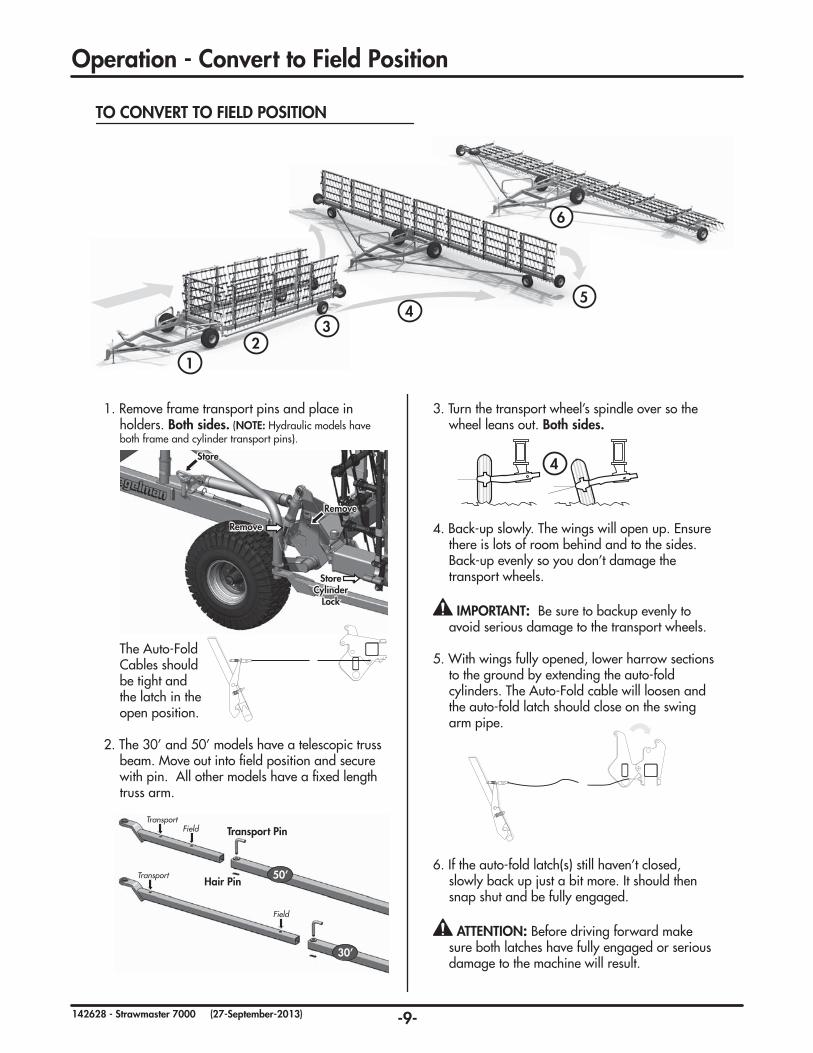
TO CONVERT TO FIELD POSITION
1. Remove frame transport pins and place in holders. Both sides. (NOTE: Hydraulic models have both frame and cylinder transport pins).
The Auto-Fold Cables should be tight and
the latch in the open position.
2. The 30’ and 50’ models have a telescopic truss
beam. Move out into field position and secure with pin. All other models have a fixed length truss arm.
3. Turn the transport wheel’s spindle over so the wheel leans out. Both sides.
4. Back-up slowly. The wings will open up. Ensure there is lots of room behind and to the sides. Back-up evenly so you don’t damage the transport wheels.
IMPORTANT: Be sure to backup evenly to avoid serious damage to the transport wheels.
5. With wings fully opened, lower harrow sections to the ground by extending the auto-fold cylinders. The Auto-Fold cable will loosen and the auto-fold latch should close on the swing arm pipe.
6. If the auto-fold latch(s) still haven’t closed, slowly back up just a bit more. It should then snap shut and be fully engaged.
ATTENTION: Before driving forward make sure both latches have fully engaged or serious damage to the machine will result.
Field
Transport
Transport Pin
Hair Pin50’
30’
FieldTransport
4
45
6
32
1

-10-142628 - Strawmaster 7000 (27-September-2013)
Operation - Suggested Tine Angle Settings
The following lists suggested tine angle settings. Since there are no standard angles for running the tines, the operator may adjust the tine angles as required to achieve desired results.
REMEMBER:
• actual settings will vary with tine wear.
• ensure trailer and frame are leveled properly. (Refer to the “Height Adjustment” section.)
REMEMBER WHEN OPERATING: • straw should be dry.
• if machine leaves clumps of straw, apply slight down pressure by extending hydraulic lift cylinders.
MACHINE PREPARATION
• Remove auto-fold cable pins on the 8”x 8” beam side. Loop the unfastened end of each cable around the cart frame and clip together (or remove auto-fold cable completely). By simply removing one bolt on each axle, remove both transport wheel assemblies.
THE FIELD
• Work the field at 45 degrees to the seeding line.
• In order to rake flax straw some down pressure is required.
• Before built-up straw starts to spill out the back of the machine dump straw load by lifting harrow sections.
RAKING4321
• Begin operating Strawmaster with the lift hydraulics in float position, if more compaction is required, rotate 8”x8” beam by extending main lift cylinders.
• To avoid deep ridges in your field, reduce down pressure and operate at lower speeds; 5 - 6 mph.
• If packing is done after seeding, make sure to check that seed is not being disturbed.
• To prevent tine damage, avoid tight turning.
FIELDPACKING4321
• For best results operate at 10 - 12 mph
• The straw built up in the harrow sections helps to achieve maximum rub action to break down straw.
TOUGH STRAW
• Advance the tine angle to a more aggressive setting. This will hold straw for a longer period of time, allowing for a more even distribution of residue. REMEMBER: Breaking down straw is much more effective in dry conditions.
• A second pass may be required in extremely heavy straw conditions. (Work the second pass at a 45 degree angle to how it was worked the first time).
BREAKING&SPREADINGSTRAW4321
• Increasing downward pressure will help break the soil crust and place the granule in contact withmoist soil.
• Avoid straw build up in the first two rows of tines.This makes for a more even granule or seedbroadcast.
IMPORTANT: Always follow label directions forchemical herbicides.
• Valmar Airflow offers all the necessary hardwarerequired to neatly install their applicator on theStrawmaster 7000. The Valmar Airflow Model 3255can be used with the 50’, 70’ & 82’ Strawmasters.The Model 2055 can be used on the 30’ and 50’Strawmasters.
CHEMICAL INCORPORATION4321

-11-142628 - Strawmaster 7000 (27-September-2013)
Operation - Height Adjustment
Tine angle adjustment should be made with the machine in field position. For suggested initial settings with new tines, refer to the “Suggested Tine Angle Settings” section.
To manually adjust tine angle: Rotate the sidewind jacks located on each harrow section. Start at one end, set as desired. Set all the other sections to the same setting.
To hydraulically adjust tine angle: Retract rephasing tine angle cylinders to raise tines. Extend cylinders to lower.
TINE ANGLE ADJUSTMENT
The trailer frame hitch should be parallel to the ground when operating. It will be necessary to adjust the hitch clevis height each time the trailer height is adjusted due to tine wear.
To adjust the hitch clevis location, hook-up the tractor to the trailer hitch, following the procedure in the section “Hook-up/Unhooking”. Stand back and check to see if the trailer hitch is parallel to the ground. If not, use the sidewind jack to raise the trailer hitch and centre the clevis to the drawbar. Remove the clevis mounting pins and move the clevis up or down as required. Install the clevis mounting pins and retainers. Lower the trailer hitch.
Stand back to check if the trailer hitch is level. If not, repeat procedure.
HITCH CLEVIS ADJUSTMENT
Trailer height will require adjustment as the tines wear down, or as the tine angle is increased.
Trailer height is adjustable either hydraulically or manually with the use of two ratchet jacks, each located on the trailer wheel arms.
To manually adjust trailer height: Begin with the machine in field position. Make sure the tine angle has been set, if necessary. Use the ratchet jack handle for adjustment. Adjust ratchet jacks evenly until tines are set to a desired height. If trailer frame cannot be lowered any further, replace tines or check tine angle.
When adjustments are complete, check that the trailer frame is parallel to the ground. If not, adjust clevis height and re-check. Repeat if necessary.
TRAILER HEIGHT ADJUSTMENT
NOTE: Stawmasters can have either manual or hydraulic adjustment. Trailer height & tine angle are set by either ratchet/sidewind jacks or hydraulics.
If trailer height is set correctly it will be even with harrows and...
Front & back tines apply equal pressure Front tines not applying pressure Front tines applying too much pressure
If trailer is too high... If trailer is too low...
With the machine in field position, the wing beams and centre beam should be at the same height, parallel to the ground. Adjustment to the wing beam height is required when the tines wear down, the tine angle is adjusted, or the trailer height is adjusted.
To manually adjust height: Rotate the sidewind jack to raise or lower the wing beam section, until desired height is achieved.
The hydraulic adjustment option also includeds a fine adjustment rod on the top endwheel linkage.
WING BEAM HEIGHT ADJUSTMENT
Fine Adjustment

-12-142628 - Strawmaster 7000 (27-September-2013)
Operation
Follow this procedure when preparing to transport:
1. Clear the area of bystanders, especially small children, before converting into transport configuration.
2. Operate the lift hydraulics to raise the harrow sections.
3. Carefully drive forward. The wing beams should fold back into transport position.
4. Install the transport pins.
5. 30’ & 50’ models only: Remove the black pin on the truss beam. Rotate the swingarm back to slide the truss beam in and line up holes. Install pin and secure with hair clip.
6. Clean the SMV sign, lights and reflectors.
7. Use hazard flashers on tractor unless prohibited by law.
8. Maintain a safe speed. Slow down when cornering on rough roads, and pull off to the side of the road when meeting traffic.
9. To ensure minimum tire wear, be sure the bent axle at the rear of each wing beam is oriented so that the rear transport tires are completely upright.
TRANSPORT
After the season’s use, completely inspect all major systems of the machine. Repair or replace any worn or damaged components to prevent unnecessary down time at the beginning of next season.
Since the unit can be used in extremely adverse conditions during the season, the machine should be carefully prepared for storage to ensure that all dirt, mud, debris and moisture has been removed.
Follow this procedure when preparing to store:
1. Wash the entire machine thoroughly using a water hose or pressure washer to remove all dirt, mud, debris or residue.
2. Inspect all parts to see if anything has become entangled in them. Remove the entangled material.
3. Lubricate all grease fittings to remove any moisture in the bearings.
4. Inspect all hydraulic hoses, fittings, lines and couplers. Tighten any loose fittings. Replace any hose that is badly cut, nicked or abraded or is separating from the crimped end of the fitting.
5. Touch up all paint nicks and scratches to prevent rusting.
6. Oil the exposed rams on the hydraulic cylinder to prevent rusting.
7. Select an area that is dry, level and free of debris.
8. Follow the procedure given in the section “Hook-Up/Unhooking” when unhooking.
STORAGE
RIDERS
TRANSPORT SAFETY
• Use only a drawbar pin with a mechanical retainer, and a safety chain.
• Clean the SMV sign, lights and reflectors before starting.
• Always use hazard flashing lights on tractor.
• Travel at a safe speed. Use care when making corners or meeting traffic.
• Under no circumstances should there ever be riders while the Strawmaster® is in transport.
STORAGE SAFETY
• Store in an area away from human activity.
• Do not allow children to play on or around the stored unit.
Field
Transport
Transport Pin
Hair Pin50’
30’
FieldTransport

-13-142628 - Strawmaster 7000 (27-September-2013)
Service&Maintenance
End Wheel Cylinder (x2)or Sidewind Jack (x2)
Sidewind Jacks Harrow Sections(Manual adjustable models)
Hub-Transport Wheel (2x)
Hub-End Wheel (2x)
Upper&lowerwheel plates (x2)
Auto-Fold Cylinder (x2)
Hub - Trailer Wheel (x2)
Trailer Wheel Cylinder (x2)orRatchet-Jack (x2)
Center Beam Pin &CrossJoints(x2)
GREASINGUse an SAE multipurpose grease with extreme pressure (EP) performance. Also acceptable is an SAE multipurpose lithium base grease.
1. Use only a hand-held grease gun for all greasing.
2. Wipe grease fitting with a clean cloth before greasing, to avoid injecting dirt.
3. Replace and repair broken fittings immediately.
4. If fittings will not take grease, remove and clean thoroughly. Also clean lubricant passageway. Replace fitting if necessary.
5. Inject grease until you see grease being expelled from the bearing or bushing areas.
SERVICE
MAINTENANCE SAFETY
• Stop tractor engine, set park brake and remove ignition key before servicing, adjusting, repairing or maintaining.
• Be careful when working around or maintaining a high pressure hydraulic system. Wear the proper hand and eye protection when searching for a pin hole leak in a hose or fitting.
• Place safety stands or large blocks under the frame before removing the tires or working beneath the machine.
Maintenance Checklist
Dailly - 8 Hours
• Hydraulic Fluid Leaks
• Damaged Hoses
• Check Tire Pressure
Cart/TrailerTires:
16.5L x16.1 - 6 PLY 48 PSI (330 kPa)
Transport Tires (70’, 62’, 50’, 30’):
9.5L x15 - 6 PLY 36 PSI (248 kPa)
-or- 9.5L x15 - 8 PLY 60 PSI (414 kPa)
Transport Tires (82’):
11L x15 - 12 PLY 90 PSI (620 kPa)
Endwheel Tires:
9.5L x15 - 6 PLY 36 PSI (248 kPa)
-or- 9.5L x15 - 8 PLY 60 PSI (414 kPa)
Weekly - 25 Hours
• Working Points & Pins
• Tine Wear
• Safety Signs Clean
Annually - 200 Hours
• Bolt Tightness
• Wheel Bearings
• Latch Mechanism
• Cable Assembly
TORQUE
all hardware

-14-142628 - Strawmaster 7000 (27-September-2013)
The tables shown below give correct torque values for various bolts and capscrews. Tighten all bolts to the torques specified in chart unless otherwise noted. Check tightness of bolts periodically, using bolt torque chart as a guide. Replace hardware with the same strength bolt.
Service&Maintenance
CHECKINGBOLTTORQUE
METRICTORQUESPECIFICATIONS
Metric Torque Values(basedon“Dry”values)
Size Class 8.8 Class 10.9 lb.ft (N.m) lb.ft (N.m) M6 8.5 (11) 12 (17) M8 20 (28) 30 (40) M10 40 (55) 60 (80) M12 70 (95) 105 (140) M14 110 (150) 165 (225) M16 175 (240) 255 (360) M18 250 (330) 350 (475) M20 350 (475) 500 (675) M22 475 (650) 675 (925) M24 600 (825) 850 (1150)
IMPERIALTORQUESPECIFICATIONS
Unified Inch Torque Values(basedon“Dry”values)
Size Grade 5 Grade 8 lb.ft (N.m) lb.ft (N.m) 1/4” 9 (12) 12.5(17) 5/16” 18 (25) 26 (35) 3/8” 33 (44) 46 (63) 7/16” 52 (70) 75 (100) 1/2” 80 (110) 115 (150) 9/16” 115 (155) 160 (225) 5/8” 160 (215) 225 (300) 3/4” 280 (375) 400 (550) 7/8” 450 (625) 650 (875) 1” 675 (925) 975 (1300)
HARDWARE/HOSESPECIFICATIONS
Unless otherwise stated:
• Hardware - Hex, Plated GR5 UNC (imperial) or P8.8 (metric)
• Hoses - 3/8, ends come with 3/4 JIC female swivel.
TORQUE
all hardware
TIGHTENING FLARE TYPE TUBE FITTINGS *
1. Check flare and flare seat for defects that might cause leakage.
2. Align tube with fitting before tightening.
3. Lubricate connection and hand tighten swivel nut until snug.
4. To prevent twisting the tube(s), use two wrench-es. Place one wrench on the connector body and with the second tighten the swivel nut to the torque shown.
*The torque values shown are based on lubricatedconnections as in reassembly.
Hydraulic Fitting Torque* Size lb.ft (N.m) 1/2 34 (46) 3/4 75 (100) 7/8 90 (122)
HYDRAULICFITTINGTORQUE
SAE-8SAE-5SAE-2
5.8 8.8 10.9

-15-142628 - Strawmaster 7000 (27-September-2013)
Service&Maintenance
IMPORTANT: Be sure to block up unit securely before removing tires.
DISASSEMBLY
1. Carefully pry off dust cap.
2. Remove cotter pin from nut.
3. Remove nut and washer.
4. Pull hub off spindle.
5. Dislodge the inner cone bearing and dust seal.
6. Inspect cups that are press fitted into hub for pits or corrosion and remove if necessary.
7. Inspect and replace defective parts with new ones.
WHEEL HUB REPAIR
WHEELBOLTTORQUE
1. The Recommended bolt torque for this implement is 80-90 ft.lbs.
2. When attaching the wheel, tighten to this specifications. Check again after approximately 500 revolutions and re-tighten as required.
3. Check wheel bolts twice annually to ensure proper bolt torque.
ASSEMBLY
1. If cups need replacing, be careful to install them gently and evenly into hub until they are fully seated.
2. Apply a thick wall of grease inside hub. Pack grease in cones.
3. Install dust seal as illustrated, and inner cone.
4. Position hub onto spindle and fill surrounding cavity with grease.
5. Assemble outer cone, washer and nut.
6. Tighten nut while rotating hub until there is a slight drag.
7. Turn nut back approximately 1/4 turn to align cotter pin hole with notches on nut. Note: Hub should rotate freely. If not, repeat step 6.
8. Install cotter pin and bend legs sideways over nut.
9. Fill dust cap half full of grease and gently tap into position.
10. Pump grease into hub through grease fitting until lubricant can be seen from dust seal.
SpindleInner Cone
Valve Stem
Wheel Bolts
Lock Nuts
RimTire
Inner CupHub
Dust Seal
Outer ConeOuter Cup
Cotter Pin
Slotted NutWasher
Dust Cap
COMMON WHEEL AND HUB COMPONENTS
CHECKTIREPRESSURECart/TrailerTires: 16.5L x16.1 - 6 PLY 48 PSI (330 kPa)
Transport Tires (70’, 62’, 50’, 30’): 9.5L x15 - 6 PLY 36 PSI (248 kPa)-or- 9.5L x15 - 8 PLY 60 PSI (414 kPa)
Transport Tires (82’): 11L x15 - 12 PLY 90 PSI (620 kPa)
Endwheel Tires: 9.5L x15 - 6 PLY 36 PSI (248 kPa)-or- 9.5L x15 - 8 PLY 60 PSI (414 kPa)

-16-142628 - Strawmaster 7000 (27-September-2013)
Service&Maintenance
When cylinder repair is required, clean off unit, disconnect hoses and plug ports before removing cylinder.
NOTE: Complete rebuilt cylinders may be available. Contact your dealer for further information.
DISASSEMBLY
1. Loosen lock ring and turn off end cap.
2. Carefully remove piston, rod and cap combination.
3. Disassemble piston from rod by removing lock nut.
NOTE: DO NOT clamp rod by chrome surface.
4. Slide off end cap.
5. Remove seals and inspect all parts for damage.
6. Install new seals and replace damaged parts with new components.
ASSEMBLY
1. Reinstall rod through end cap.
2. Secure piston to rod with lock nut. Torque to 225 ft-lb (305 N·m).
3. With cylinder body held gently in a vise, insert piston and rod combination using a slight rocking motion.
4. Thread lock ring fully onto barrel.
5. Turn end cap fully against lock ring then back off end cap to align ports.
6. Tighten lock ring against end cap using a punch and hammer.
HYDRAULIC CYLINDER REPAIR
COMMON DEGELMAN CYLINDER COMPONENTS
Barrel
RodAssembly
Lock NutLock Ring
End Cap
Flat Washer
O-ring
Rod SealWear Ring
Piston
PinAssembly
Shoulder Bolt
Piston Seals
(5 part)
O-ring
Rod Wiper Seal

-17-142628 - Strawmaster 7000 (27-September-2013)
DISASSEMBLY:
Follow this procedure one pipe row at a time so pipes do not get mixed up, or number each pipe before disassembly.
1. Remove the bolt from the link bar to pipe lug, so pipe will rotate freely.
2. Remove the pin from the back end of the jack if the back row is being replaced. (Not Shown)
3. Remove the bolts and spacer from the bracket on the sides of the frame. The row will drop out.
4. Remove the bolts holding the tines on the pipe. (Starting at each end and working in)
5. Slide the tines off the pipe.
ASSEMBLY:
1. Slide the tines onto the pipe. (Make sure all tines are installed facing the same direction)
2. Position tines centred over bolt holes as shown in the diagram. Install bolts and nuts.
3. Position pipe between the brackets on the sides of the frame, with the lug on the outside of the frame. Install the spacer and bolt, secure with locknut. Ensure pipe turns freely when tightening.
4. Line up hole on lug with hole on link bar, install bolt and secure with nut.
5. Back row: Install pin through the jack and lug. Secure with hair clip. (Not Shown)
6. See the adjustments section and adjust as required.
Note: Tines must be replaced when worn down to 16 in. or less in length. Tines may be replaced while the machine is in transport position, or field position.
NOTE: Avoid replacing one tine at a time, unless wear is minimal. Tines should be replaced all at once whenever possible so there is even wear to all the tines. In some instances, (raking operations) the front row of tines will wear sooner. If this is the case, replace the front row. Check that wear is minimal on the other tines.
TINE REPLACEMENT
Link Bar
Pipe Lug
Back Row
Service&Maintenance-TineReplacement

-18-142628 - Strawmaster 7000 (27-September-2013)
Service&Maintenance
Synchronized operation of two or more hydraulic cylinders in unbalanced load conditions can be attained by plumbing volumetrically matched cylinders adjacent to each other where the displaced fluid produces, equal, simultaneous, actuation of each cylinder in the system.
As the volumes of each cylinder cannot economically, be identically matched, a bypass port is provided that upon full extension (or retraction) a metered amount of fluid bypasses the piston seal to the next adjacent cylinder in the system.
This indexes all cylinders of the system to the sames position, then upon retraction (extension) positive sealing is engaged and sychronized operation continues (to ensure optimum performance all entrapped air must be purged from these rephasing cylinder systems).
REPHASING CYLINDER SYSTEM - TINE ANGLE
The cable may stretch after a period of time. The latch assembly may not swing over far enough to allow the swing arm shaft to clear.
To adjust the latch assembly, start with the machine in transport position. Tighten the nut on the eyebolt until the end of the swing arm shaft clears the latch assembly.
To check the clearance: Remove the truss beam from the swing arm and swing forward to check the clearance. Or, follow the procedure to convert to machine to field position.
Repeat adjustment procedure if required.
AUTOFOLD LATCH ADJUSTMENT
Latch Assembly
Latch Holder
Cable Assembly
Eye Bolt
Swing Arm
NOTE: Allow minimal clearance between swing arm and latch.
REPLACEMENT DECALS AND REFLECTORS
Trailer frame142438 - Strawmaster 7000 (2)142383 - Caution, 6 Points (1)142368 - Important, Install Pin (2)142008 - Degelman - 6” x 25-3/4” (2)143162 - Manual Holder Decal (1)142279 - Reflector, Amber - 3-1/4” (2)
Auto-fold Arm142439 - Important, Back-up Evenly (2)142280 - Reflector, Red 6-1/4” (2)142279 - Reflector, Amber - 3-1/4” (2)
Harrow Section Frame142010 - Degelman, 2-3/4” x 12” (1)

-19-142628 - Strawmaster 7000 (27-September-2013)
Troubleshooting
TROUBLESHOOTING
In the following section, we have listed some of the problems, causes and solutions that you may encounter. If you encounter a problem that is difficult to solve, even after having read through this troubleshooting section, please call your local dealer or distributor. Before you call, have this manual and the serial number from your unit ready.
PROBLEM
Hydraulics creep down during operation.
Harrow sections raisetoo slowly.
Oil accumulation on cylinder shaft.
Auto-Fold latch will notclose for field position.
Auto-Fold latch will notopen for transport position.
Machine won’t unfoldfast enough.
Auto-Fold unlatchesprematurely.
CAUSE
Tractor hydraulic leak.
Damaged hose or loose fittings.
Hydraulic cylinder leak.
Hydraulic pressure fromtractor too low.
Restriction in hose.
External hydraulic leak.
Hydraulic cylinder leak.
Oil bypassing seals.
Latch holder has slidback on trailer frame.
Cable slack or broken.
Transport wheel might be in transport position.
The latch is too loose onthe swing arm pipe.
SOLUTION
To verify, raise sections half way up, disconnect at tractor. Observe if sections creeps down. If not repair tractor hydraulics.
Search for leaks with a piece of paper (not by hand). Repair as necessary.
Replace seals or damaged components.
Check pressure, should be 2500 psi.
Disconnect & blow out lines with compressed air.
Repair as needed.
Replace seals or damaged components.
Seal manufacturer advises that small amounts of oil getting past seals is desirable. If problem becomes excessive, replace seals.
With machine in field position and sections raised up adjust latch holder in slotted bolt holes to meet the swing arm pipe.
Tighten or replace.
Switch transport wheel over to field position by rotating the bent spindle until the wheel is leaning out.
Latch holder has moved forward on the trailer frame. Move it back.
-20-142628 - Strawmaster 7000 (27-September-2013)
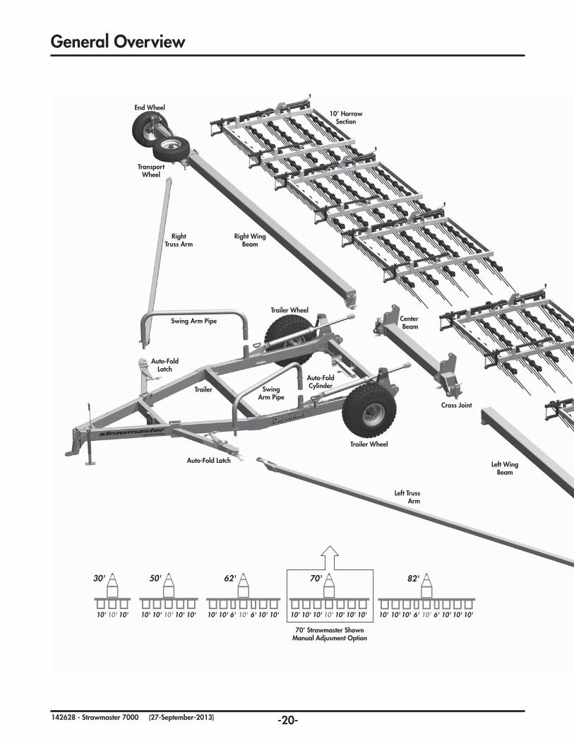
GeneralOverview
End Wheel
Transport Wheel
Trailer Wheel
Trailer Wheel
Trailer
Left Truss Arm
Right Truss Arm
Swing Arm Pipe
Swing Arm Pipe
Auto-Fold Cylinder
Center Beam
Cross Joint
Auto-Fold Latch
Auto-Fold Latch
Right Wing Beam
Left Wing Beam
10’ Harrow Section
70’ Strawmaster ShownManual Adjusment Option
30'
10' 10' 10' 10'10' 10' 10' 10' 10'10' 10' 10' 10'6'6'
50' 70' 82'62'
10'10' 10'10' 10'10' 10'10'10'10'10' 10' 10' 10' 6'6'
82'
10'10' 10'10' 10'10' 10'6'6'
30'
10' 10' 10' 10'10' 10' 10' 10'
50' 70'
10'10'10'10' 10' 10' 10'

-21-142628 - Strawmaster 7000 (27-September-2013)
NOTE: Stawmaster trailer height & tine angle adjustment is available with manual adjustment (standard) or hydraulic adjustment (optional). Hydraulic Auto-Fold is standard on all models.
Parts Section - Table of Contents
End Wheel
Transport Wheel
10’ Harrow Section
IMPORTANT:
READ MANUAL
General Overview 20-21
Wing Beam & Truss Arms 22
Trailer Components & Auto-Fold Cylinder 23-24
Auto-Fold Latch Components 25
Trailer Wheel Components & Cylinder 26
Center Beam Joint Components 27
Transport Wheel & Truss Arm Brackets 28
Transport Wheel Components 29
End Wheel Components & Cylinder 30-32
Harrow Sections & Components 32-34
Rephasing Cylinder Components 35
Optional Accessories - Valmar Platform 35
Auto-Fold Cylinder Hydraulic Hose Routing 38
Lift Cylinder Hydraulic Hose Routing (Optional) 37
Rephasing Hydraulics - 30’, 50’, & 62’ (Optional) 38
Rephasing Hydraulics - 70’, & 82’ (Optional) 40
Electrical Components & Routing 42
Warranty 44
-22-142628 - Strawmaster 7000 (27-September-2013)
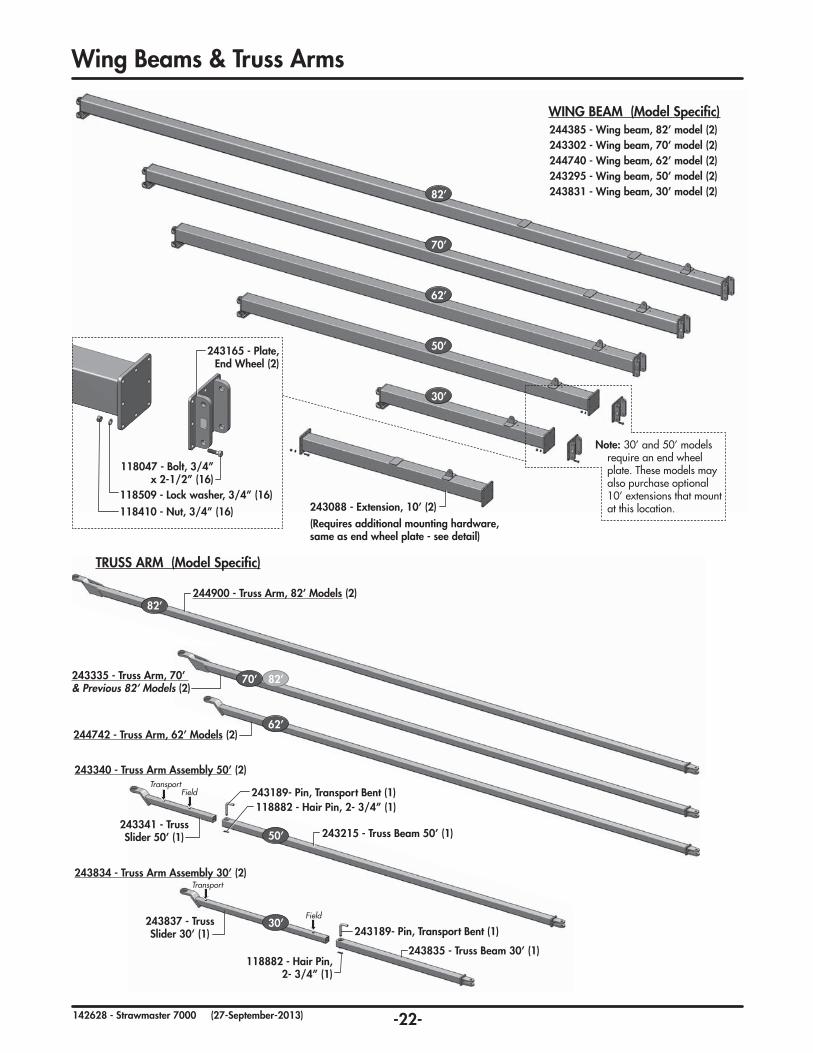
WingBeams&TrussArms
243088 - Extension, 10’ (2)(Requires additional mounting hardware, same as end wheel plate - see detail)
244385 - Wing beam, 82’ model (2)243302 - Wing beam, 70’ model (2)244740 - Wing beam, 62’ model (2)243295 - Wing beam, 50’ model (2)243831 - Wing beam, 30’ model (2)82’
70’
62’
50’
30’
118047-Bolt,3/4”x2-1/2”(16)
118509-Lockwasher,3/4”(16)118410-Nut,3/4”(16)
243165 - Plate, End Wheel (2)
Note: 30’ and 50’ models require an end wheel plate. These models may also purchase optional 10’ extensions that mount at this location.
WING BEAM (Model Specific)
243834 - Truss Arm Assembly 30’ (2)
243215 - Truss Beam 50’ (1)
243835 - Truss Beam 30’ (1)
243341 - Truss Slider 50’ (1)
Field
Field
Transport
Transport
243837 - Truss Slider 30’ (1)
243189- Pin, Transport Bent (1)
243189- Pin, Transport Bent (1)
118882-HairPin,2-3/4”(1)
118882 - Hair Pin, 2-3/4”(1)
243340 - Truss Arm Assembly 50’ (2)
50’
30’
TRUSS ARM (Model Specific)
244900 - Truss Arm, 82’ Models (2)
243335 - Truss Arm, 70’ & Previous 82’ Models (2)
244742 - Truss Arm, 62’ Models (2)
82’
82’
70’
62’
-23-142628 - Strawmaster 7000 (27-September-2013)
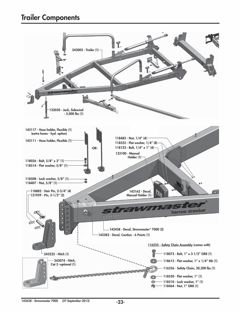
Trailer Components
243005 - Trailer (1)
132030 - Jack, Sidewind - 5,000 lbs (1)
-OR-
118483-Nut,1/4”(4)
118407-Nut,5/8”(1)
118464 - Nut, 1” GR8 (1)
121959-Pin,5-1/2”(2)
118123-Bolt,1/4”x1”(4)
118026-Bolt,5/8”x2”(1)
118073-Bolt,1”x3-1/2”GR8(1)
118555-Flatwasher,1/4”(8)
118514-Flatwasher,5/8”(1)
118615-Flatwasher,1”x1/4”thk(1)
243225 - Hitch (1)
116256 - Safety Chain, 20,200 lbs (1)
143111 - Hose holder, Flexible (1)
143117 - Hose holder, Flexible (1)(extra hoses - hyd. option)
118508-Lockwasher,5/8”(1)
118510 - Lock washer, 1” (1)
118520 - Flat washer, 1” (1)
118882-HairPin,2-3/4”(4)
133100 - Manual Holder (1)
116255 - Safety Chain Assembly (comes with)
142438 - Decal, Strawmaster® 7000 (2)
143162 - Decal, Manual Holder (1)
142383 - Decal, Caution - 6 Points (1)
243074 - Hitch, Cat 5 -optional (1)
-24-142628 - Strawmaster 7000 (27-September-2013)
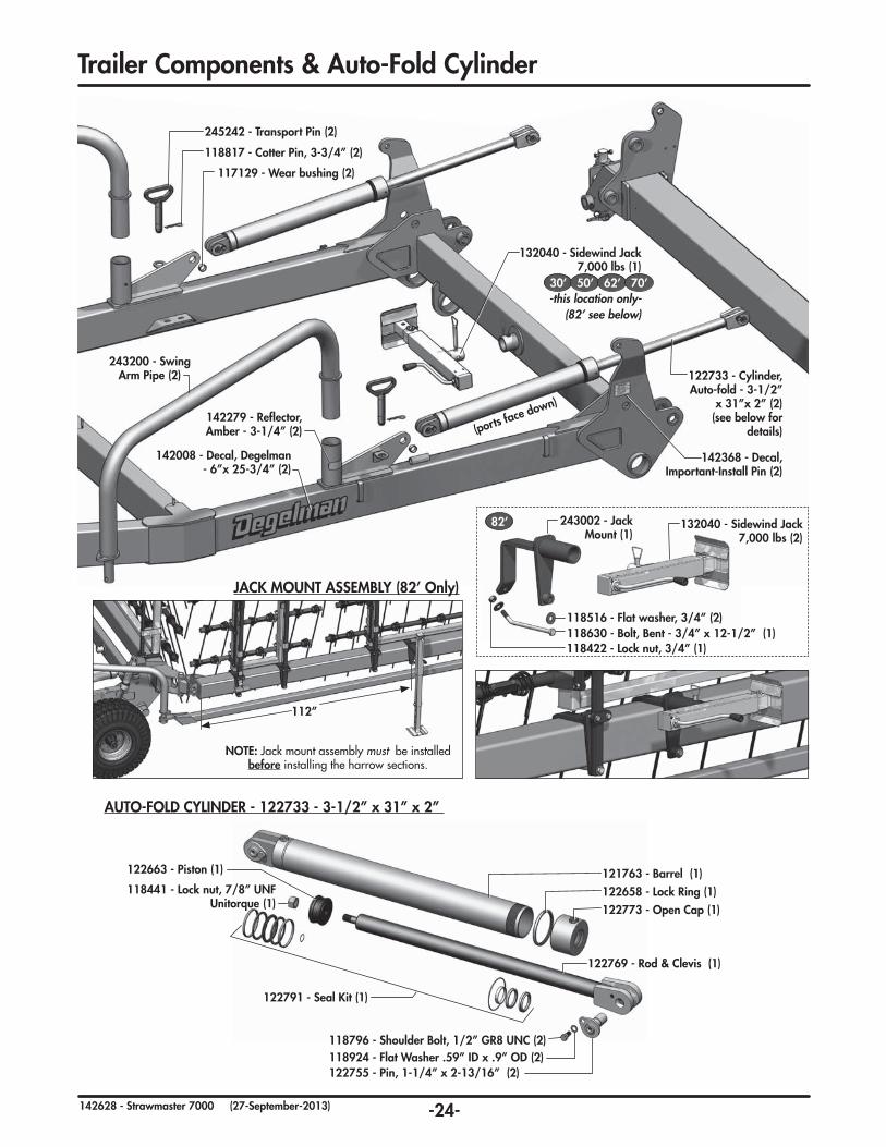
TrailerComponents&Auto-FoldCylinder
243200 - Swing Arm Pipe (2)
142008 - Decal, Degelman -6”x25-3/4”(2)
142368 - Decal, Important-Install Pin (2)
117129 - Wear bushing (2)
118817-CotterPin,3-3/4”(2)
132040 - Sidewind Jack 7,000 lbs (1)
-this location only-(82’ see below)
245242 - Transport Pin (2)
122733 - Cylinder, Auto-fold-3-1/2”
x 31”x 2” (2)(see below for
details) (ports face down)
118924 - Flat Washer .59” ID x .9” OD (2)118796-ShoulderBolt,1/2”GR8UNC(2)
122755-Pin,1-1/4”x2-13/16”(2)
122769-Rod&Clevis(1)
121763 - Barrel (1)122658 - Lock Ring (1)122773 - Open Cap (1)
122663 - Piston (1)
118441-Locknut,7/8”UNFUnitorque (1)
122791-SealKit(1)
AUTO-FOLDCYLINDER-122733-3-1/2”x31”x2”
30’ 50’ 62’ 70’
142279 - Reflector,Amber-3-1/4”(2)
82’ 132040 - Sidewind Jack 7,000 lbs (2)
118630-Bolt,Bent-3/4”x12-1/2”(1)
243002 - Jack Mount (1)
118516-Flatwasher,3/4”(2)
118422-Locknut,3/4”(1)
112”
NOTE: Jack mount assembly must be installed before installing the harrow sections.
JACKMOUNTASSEMBLY(82’Only)
-25-142628 - Strawmaster 7000 (27-September-2013)
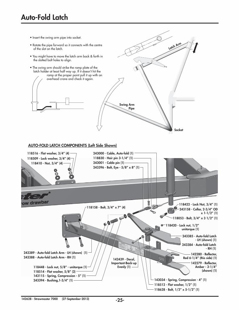
AUTO-FOLD LATCH COMPONENTS (Left Side Shown)
243389 - Auto-fold Latch Arm - LH (shown) (1)243388 - Auto-fold Latch Arm - RH (1)
118158-Bolt,3/4”x7”(4)
118410-Nut,3/4”(4) 243001 - Cable pin (1)243396-Bolt,Eye-5/8”x8”(1)
118420-Locknut,1/2”unitorque (1)
243385 - Auto-fold Latch - LH (shown) (1)
243384 - Auto-fold Latch - RH (1)
143034 - Spring, Compression - 4” (1)
118448-Locknut,5/8”-unitorque(1)
243394-Bushing,1-3/4”(1)143115 - Spring, Compression - 5” (1)118514-Flatwasher,5/8”(2)
118512-Flatwasher,1/2”(1)118628-Bolt,1/2”x5-1/2”(1)
118509-Lockwasher,3/4”(4) 118830-Hairpin3-1/4”(1)118516-Flatwasher,3/4”(4) 243000 - Cable, Auto-fold (1)
118053-Bolt,3/4”x31/2”(1)
243158-Collar,2-3/4”ODx1-1/2”(1)
118422-LockNut,3/4”(1)
Swing Arm Pipe
Socket
Auto-Fold Latch
• Insert the swing arm pipe into socket.
• Rotate the pipe forward so it connects with the centre of the slot on the latch.
• You might have to move the latch arm back & forth in the slotted bolt holes to align.
• The swing arm should strike the ramp plate of the latch holder at least half way up. If it doesn’t hit the
ramp at the proper point pull it up with an overhead crane and check it again.
Latch Arm
142439 - Decal, Important-Back-up
Evenly(1)142279 - Reflector,
Amber-3-1/4”(shown) (1)
142280 - Reflector,Red6-1/4”(thisside)(1)
-26-142628 - Strawmaster 7000 (13-November-2014)
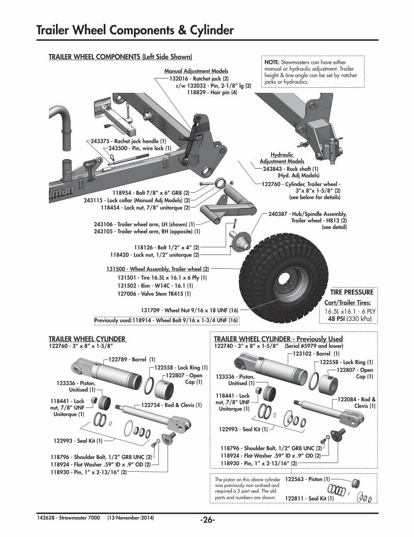
Trailer Wheel Components & Cylinder
TRAILER WHEEL COMPONENTS (Left Side Shown)
118126 - Bolt 1/2” x 4” (2)
118954 - Bolt 7/8” x 6” GR8 (2)
243375 - Rachet jack handle (1)(ports face up)
243500 - Pin, wire lock (1)
243115 - Lock collar (Manual Adj Models) (2)
243843 - Rock shaft (1) (Hyd. Adj Models)
122760 - Cylinder, Trailer wheel - 3”x 8”x 1-5/8” (2)
(see below for details)
118454 - Lock nut, 7/8” unitorque (2)
Hydraulic Adjustment Models
243106 - Trailer wheel arm, LH (shown) (1)243105 - Trailer wheel arm, RH (opposite) (1)
240387 - Hub/Spindle Assembly, Trailer wheel - H812 (2)
(see detail)
118420 - Lock nut, 1/2” unitorque (2)
Manual Adjustment Models132016 - Ratchet jack (2)
c/w 132032 - Pin, 2-1/8” lg (2)118829 - Hair pin (4)
127006 - Valve Stem TR415 (1)
131709 - Wheel Nut 9/16 x 18 UNF (16)
Previously used:118914 - Wheel Bolt 9/16 x 1-3/4 UNF (16)
NOTE: Stawmasters can have either manual or hydraulic adjustment. Trailer height & tine angle can be set by ratchet jacks or hydraulics.
131500 - Wheel Assembly, Trailer wheel (2)
131501 - Tire 16.5L x 16.1 x 6 Ply (1)131502 - Rim - W14C - 16.1 (1)
TRAILER WHEEL CYLINDER 122760 - 3” x 8” x 1-5/8”
122789 - Barrel (1)122558 - Lock Ring (1)
122807 - Open Cap (1)
122754 - Rod & Clevis (1)
118924 - Flat Washer .59” ID x .9” OD (2)118796 - Shoulder Bolt, 1/2” GR8 UNC (2)
118930 - Pin, 1” x 2-13/16” (2)
123336 - Piston, Unitised (1)
118441 - Lock nut, 7/8” UNF
Unitorque (1)
122993 - Seal Kit (1)
TRAILER WHEEL CYLINDER - Previously Used122740 - 3” x 8” x 1-5/8” (Serial #5979 and lower)
123102 - Barrel (1)122558 - Lock Ring (1)
122807 - Open Cap (1)
122084 - Rod & Clevis (1)
118924 - Flat Washer .59” ID x .9” OD (2)118796 - Shoulder Bolt, 1/2” GR8 UNC (2)
The piston on this above cylinder was previously non-unitised and required a 5 part seal. The old parts and numbers are shown:
118930 - Pin, 1” x 2-13/16” (2)
123336 - Piston, Unitised (1)
118441 - Lock nut, 7/8” UNF
Unitorque (1)
122563 - Piston (1)
122811 - Seal Kit (1)
122993 - Seal Kit (1)
TIRE PRESSURECart/Trailer Tires: 16.5L x16.1 - 6 PLY 48 PSI (330 kPa)

-27-142628 - Strawmaster 7000 (27-September-2013)
TrailerWheelSpindle&CenterBeamJoint
131707-HubCTD812-c/wCups&Studs(1)
131180-BearingCup#3720(1)
131295-BearingCone#3767(1)
131184-DustSeal-CR#25100(1)131306-SpindleS812-c/wNut(1)
131071-BearingCup#2720(1)131294-BearingCone#2798(1)
118336-GreaseFitting1/4-28(1)
131706 - Hub Cap - CTD812 (1)
118835-CotterPin3/16x1-1/2(1)
118423 - Slotted Nut 1-14 UNS (1)
118553 - Flat Washer (1)
240387-HUB/SPINDLEASSEMBLY,TRAILERWHEEL-H812
CENTER BEAM JOINT COMPONENTS (Left Side Shown)
243791 - Cross Joint Assembly (1)
243370 - Centre Beam (1)
243103 - Pin, Cross Joint -12” (2)
243101-Pin,Trailer/Centre-7”(1)
118420 - Lock nut, 1/2”Unitorque(2)
118420-Locknut,1/2”-Unitorque(1)118082-Bolt,1/2”x3-1/2”(1)
118126 - Bolt, 1/2”x4”(2)
117129 - Wear bushing (1)
243001 - Cable pin (1)118830-Hairpin3-1/4”(1)243000 - Cable, Auto-fold (1)
AlsoRequires:131709-WheelNut9/16x18UNF(8)
Previouslyused:131705-HubCTD812-c/wCups(1)
-28-142628 - Strawmaster 7000 (27-September-2013)
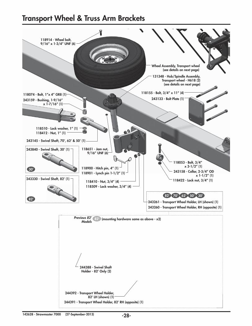
118914 - Wheel bolt, 9/16”x1-3/4”UNF(6)
118900 - Hitch pin, 4” (1)
118651 - Jam nut, 9/16”UNF(6)
118901-Lynchpin1-1/2”(1)
Wheel Assembly, Transport wheel(see details on next page)
118053-Bolt,3/4”x3-1/2”(1)
118155-Bolt,3/4”x11”(4)
131348-Hub/SpindleAssembly,Transport wheel - H618 (2)(see details on next page)
243133 - Bolt Plate (1)118074 - Bolt, 1”x 4” GR8 (1)
118510 - Lock washer, 1” (1)
118509-Lockwasher,3/4”(4)
243159-Bushing,1-9/16”x1-7/16”(1)
118412 - Nut, 1” (1)
243145-SwivelShaft,70’,62‘&50’(1)
118422-Locknut,3/4”(1)118410-Nut,3/4”(4)
243158-Collar,2-3/4”ODx1-1/2”(1)
243840-SwivelShaft,30’(1)
243261 - Transport Wheel Holder, LH (shown) (1)
243260 - Transport Wheel Holder, RH (opposite) (1)
70’ 62’ 50’ 30’
30’
82’
TransportWheel&TrussArmBrackets
244392 - Transport Wheel Holder, 82’ LH (shown) (1)
244388-SwivelShaftHolder - 82’ Only (2)
244391 - Transport Wheel Holder, 82’ RH (opposite) (1)
(mountinghardwaresameasabove-x2)Previous 82’ Models
82’
243330-SwivelShaft,82’(1)
82’

-29-142628 - Strawmaster 7000 (27-September-2013)
131349 - Spindle, Bent - 17” (1) (comes with slotted nut)
131022 - Bearing, Cone - 1.75” ID (1)
131023 - Bearing, Cup - 3.265” OD (1)
131025 - Bearing, Cup - 2.563” OD (1)131024 - Bearing, Cone - 1.375” ID (1)
131020 - Flat washer, 1” (1)
118835 - Cotter pin,1/2”(1)
118423 - Slotted nut, 1” UNS (1)
131173 - Cap, Hub - H618 (1)- or -
131701 - Cap, Hub - CTD618 (1)
131013 - Hub, H618 (1) - or -
131700 - Hub, CTD618 (1)(both come with bearing cups)
131026 - Dust seal (1)
82’
WHEEL ASSEMBLY, TRANSPORT WHEEL
HUB/SPINDLEASSEMBLY,TRANSPORTWHEEL
131062 - Transport Wheel Assembly (2) 70’, 62’, 50’, 30’c/w....127003 - Tire, 9.5L x 15 - 6 PLY (1)131001 - Rim, 6 Bolt - 15 (1)127006-Valvestem(1)
70’ 62’ 50’ 30’
131509 - Transport Wheel Assembly (alternate) (2) 70’, 62’, 50’, 30’c/w....131510 - Tire, 9.5L x 15 - 8 PLY (1)131001 - Rim, 6 Bolt - 15 (1)127006-Valvestem(1)
131348-Hub/SpindleAssembly,Transportwheel-H618
131600 - Transport wheel Assembly (82’-only) (2) c/w....131601 - Tire, 11L x 15 FI - 12 PLY (1)131001 - Rim, 6 Bolt - 15 (1)127006-Valvestem(1)
ValveStem
Rim, 6 Bolt
Tire
Transport Wheel Components
TIRE PRESSURESTransport Tires (70’, 62’, 50’, 30’): 9.5L x15 - 6 PLY 36 PSI (248 kPa) -or-9.5L x15 - 8 PLY 60 PSI (414 kPa)
Transport Tires (82’): 11L x15 - 12 PLY 90 PSI (620 kPa)

-30-142628 - Strawmaster 7000 (13-November-2014)
243186 - Pin, 8-1/8” (2) 243164 - Ring, Retaining (4)
243187 - Pin, 4-5/8” (2)
243164 - Ring, Retaining (4)
243180 - Axle holder (1)
132031 - Lock Clip, Jack Handle (1)
118882 - Hair pin, 2-3/4” (2)
132023 - Jack, Sidewind - 10” (1)
121958 - Pin, 1-3/4” (2)
243170 - Plate, Upper (1)(for Manual Jack option)
243175 - Plate, Lower (1)
122720 - Cylinder, End wheel - 2-1/2” x 8”x 1-1/4” (1)
(see detail below)
Hydraulic Adjustment Models
Manual Adjustment Models
WHEEL ASSEMBLY, END WHEEL
131062 - Transport Wheel Assembly (2) c/w.... 127003 - Tire, 9.5L x 15 - 6 PLY (1) 131001 - Rim, 6 Bolt - 15 (1) 127006 - Valve stem (1)
131509 - Transport Wheel Assembly (alternate) (2)
c/w.... 131510 - Tire, 9.5L x 15 - 8 PLY (1) 131001 - Rim, 6 Bolt - 15 (1) 127006 - Valve stem (1)
END WHEEL ASSEMBLY (Left Side Shown)
End Wheel Assembly Components
NOTE: Stawmasters can have either manual or hydraulic adjustment. Trailer height & tine angle can be set by ratchet jacks or hydraulics.
(ports face forward)
END WHEEL CYLINDER - 122720 - 2-1/2” x 8” x 1-1/4”
118924 - Flat Washer .59” ID x .9” OD (2)118796 - Shoulder Bolt, 1/2” GR8 UNC (2)
118930 - Pin, 1” x 2-13/16” (2)
122086 - Rod & Clevis (1)
123114 - Barrel (1)122725 - Lock Ring (1)122723 - Open Cap (1)
123248 - Piston, Unitised (1)
118441 - Lock nut, 7/8” UNF Unitorque (1)
122990 - Seal Kit (1)
The piston on this above cylinder was previously non-unitised and required a 5 part seal. The old parts and numbers are shown:
122726 - Piston (1)
122721 - Seal Kit (1)
Endwheel Tire Pressures: 9.5L x15 - 6 PLY 36 PSI (248 kPa) -or-9.5L x15 - 8 PLY 60 PSI (414 kPa)
244342 - Endwheel, Upper Assembly(for Hydraulic option)
Note: Models prior to Oct. 2010 (Serial #’s 5979 and lower) use a different “Trailer Wheel Cylinder”(122740 - p.26) and require a different assembly for the endwheel upper plate:244381 - Plate, Upper Assembly c/w same Rod & Nuts as shown &244382 - Upper Endwheel Plate
244347 - Upper Endwheel Plate (1)
118972 - Jam Nut, 1-1/4 (2)
244344 - Adjustment Rod, 1-1/4 (1)
Previous 1-1/4” Rod Version(s)
244761 - Upper Endwheel Plate (1)
118451 - Jam Nut, 1-1/2 (2)
244765 - Adjustment Rod, 1-1/2 (1)
244760 - Endwheel, Upper Assembly (1)(for Hydraulic option)
-31-142628 - Strawmaster 7000 (08-September-2014)
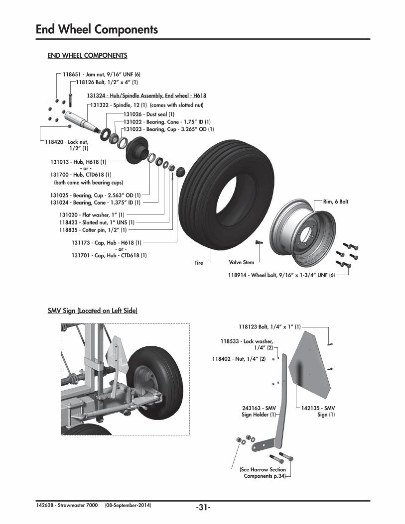
END WHEEL COMPONENTS
118914 - Wheel bolt, 9/16” x 1-3/4” UNF (6)
118651 - Jam nut, 9/16” UNF (6)
131322 - Spindle, 12 (1) (comes with slotted nut)
131026 - Dust seal (1)131022 - Bearing. Cone - 1.75” ID (1)131023 - Bearing, Cup - 3.265” OD (1)
118126 Bolt, 1/2” x 4” (1)
118420 - Lock nut, 1/2” (1)
131025 - Bearing, Cup - 2.563” OD (1)131024 - Bearing, Cone - 1.375” ID (1)
131020 - Flat washer, 1” (1)
118835 - Cotter pin, 1/2” (1)118423 - Slotted nut, 1” UNS (1)
131173 - Cap, Hub - H618 (1)- or -
131701 - Cap, Hub - CTD618 (1)
131013 - Hub, H618 (1) - or -
131700 - Hub, CTD618 (1)(both come with bearing cups)
131324 - Hub/Spindle Assembly, End wheel - H618
Valve Stem
Rim, 6 Bolt
Tire
End Wheel Components
SMV Sign (Located on Left Side)
142135 - SMV Sign (1)
243163 - SMV Sign Holder (1)
118123 Bolt, 1/4” x 1” (1)
118402 - Nut, 1/4” (2)
118533 - Lock washer, 1/4” (2)
(See Harrow Section Components p.34)
-32-142628 - Strawmaster 7000 (27-September-2013)
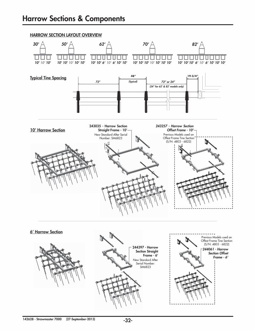
243035 - Harrow Section Straight Frame - 10’
New Standard After Serial Number: SM6823
243257 - Harrow Section Offset Frame - 10’
Previous Models used an Offest Frame Tine Section
(S/N: 4803 - 6822)
10’ Harrow Section
6’ Harrow Section
HarrowSections&Components
HARROW SECTION LAYOUT OVERVIEW
30'
10' 10' 10' 10'10' 10' 10' 10' 10'10' 10' 10' 10'6'6'
50' 70' 82'62'
10'10' 10'10' 10'10' 10'10'10'10'10' 10' 10' 10' 6'6'
82'
10'10' 10'10' 10'10' 10'6'6'
30'
10' 10' 10' 10'10' 10' 10' 10'
50' 70'
10'10'10'10' 10' 10' 10'
Typical Tine Spacing 48”
72” or 24”
19-3/4”
(24” for 62’ & 82’ models only)
(Typical)72”
244397 - Harrow Section Straight
Frame - 6’New Standard After
Serial Number: SM6823
244061 - Harrow Section Offset
Frame - 6’
Previous Models used an Offest Frame Tine Section
(S/N: 4803 - 6822)
-33-142628 - Strawmaster 7000 (27-September-2013)
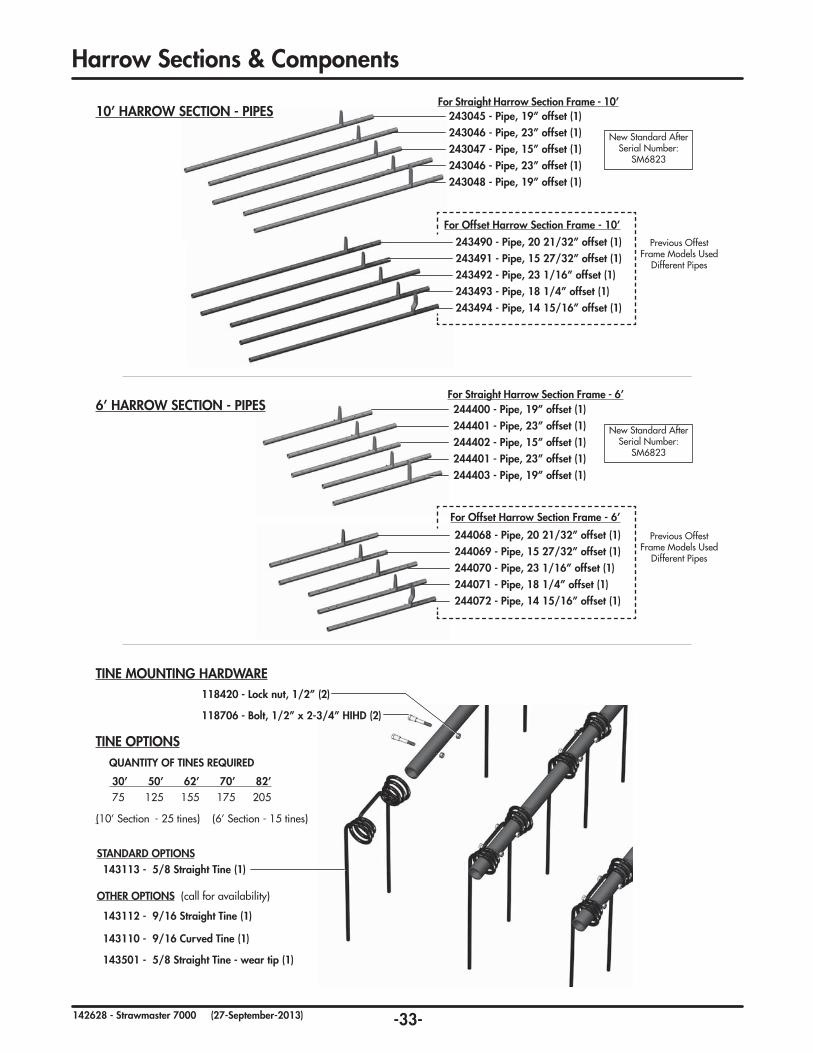
HarrowSections&Components
243045 - Pipe, 19” offset (1)243046 - Pipe, 23” offset (1)243047 - Pipe, 15” offset (1)243046 - Pipe, 23” offset (1)243048 - Pipe, 19” offset (1)
10’ HARROW SECTION - PIPES
118706-Bolt,1/2”x2-3/4”HIHD(2)
118420-Locknut,1/2”(2)
TINE MOUNTING HARDWARE
TINE OPTIONS
STANDARD OPTIONS 143113-5/8StraightTine(1)
OTHER OPTIONS (call for availability)
143112-9/16StraightTine(1)
143110-9/16CurvedTine(1)
143501-5/8StraightTine-weartip(1)
(10’ Section - 25 tines) (6’ Section - 15 tines)
QUANTITYOFTINESREQUIRED
30’ 50’ 62’ 70’ 82’ 75 125 155 175 205
244400 - Pipe, 19” offset (1)244401 - Pipe, 23” offset (1)244402 - Pipe, 15” offset (1)244401 - Pipe, 23” offset (1)244403 - Pipe, 19” offset (1)
For Straight Harrow Section Frame - 6’
For Straight Harrow Section Frame - 10’
243490-Pipe,2021/32”offset(1)243491-Pipe,1527/32”offset(1)243492-Pipe,231/16”offset(1)243493-Pipe,181/4”offset(1)243494-Pipe,1415/16”offset(1)
For Offset Harrow Section Frame - 10’
244068-Pipe,2021/32”offset(1)244069-Pipe,1527/32”offset(1)244070-Pipe,231/16”offset(1)244071-Pipe,181/4”offset(1)244072-Pipe,1415/16”offset(1)
For Offset Harrow Section Frame - 6’
6’ HARROW SECTION - PIPES
New Standard After Serial Number:
SM6823
New Standard After Serial Number:
SM6823
Previous Offest Frame Models Used
Different Pipes
Previous Offest Frame Models Used
Different Pipes

-34-142628 - Strawmaster 7000 (27-September-2013)
HarrowSections&Components
118126-Bolt,1/2”x4”(1)
118094-Bolt,5/8”x4”(2)118630-Bolt,Bent-3/4”
x12-1/2”(1)
118119-Bolt,3/4”x4”(1)
110050 - Pipe Spacer, CSTG (1)
650250 - Cast Shank Bolt Bar (1)
243333 - Bar, Spring Steel (1)
243061 Bar, Back-up (1)
243055 - Frame holder (1)
118468 - Nut, Top LockFlange1/2”(1)
118509 - Lock washer, 3/4”(1)
118508-Lockwasher,5/8”(1)
118516 - Flat washer, 3/4”(2)
118410-Nut,3/4”(1)
118407-Nut,5/8”(1)
118422-Locknut,3/4”(1)
Note: Flat side faces up. In some locations, a hydraulic holder is placed between the Spring bar and this Bolt Bar. (See Hydraulic Routing)
TYPICAL HARROW-FRAME MOUNTING COMPONENTS
TINEANGLELINKBAR-TYPICAL
118700-Locknut,5/8”UNF(5)
244017 - Indicator pointer (1)
243060 - Link bar, 5 hole (1)
118625-Bolt,5/8”x2”UNF(5)
143/4”
142823 - Gauge Decal (1)
143/4”
132031 - Lock Clip, Jack
Handle (1)
118882 - Hair pin, 2-3/4”(2)
132023Jack, Sidewind (1)
121958 - Pin, 1-3/4”(2)
Manual Adjustment Jack(Hydraulic Option Available)
Note: When tightening, ensure pipe turns freely.
-35-142628 - Strawmaster 7000 (13-November-2014)
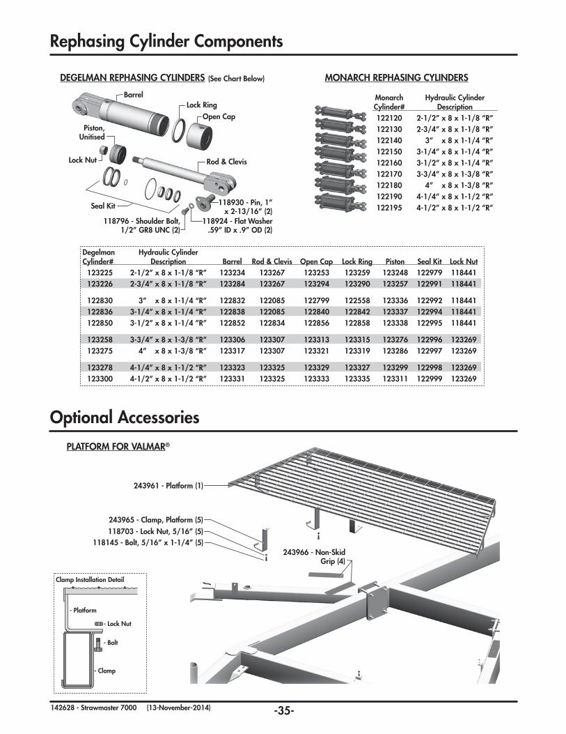
Rephasing Cylinder Components
Optional Accessories
PLATFORM FOR VALMAR®
243961 - Platform (1)
243966 - Non-Skid Grip (4)
243965 - Clamp, Platform (5)118703 - Lock Nut, 5/16” (5)
118145 - Bolt, 5/16” x 1-1/4” (5)
- Platform
- Clamp
- Lock Nut
- Bolt
Clamp Installation Detail
DEGELMAN REPHASING CYLINDERS
Degelman Hydraulic Cylinder Cylinder# Description Barrel Rod & Clevis Open Cap Lock Ring Piston Seal Kit Lock Nut 123225 2-1/2” x 8 x 1-1/8 “R” 123234 123267 123253 123259 123248 122979 118441 123226 2-3/4” x 8 x 1-1/8 “R” 123284 123267 123294 123290 123257 122991 118441
122830 3” x 8 x 1-1/4 “R” 122832 122085 122799 122558 123336 122992 118441 122836 3-1/4” x 8 x 1-1/4 “R” 122838 122085 122840 122842 123337 122994 118441 122850 3-1/2” x 8 x 1-1/4 ”R” 122852 122834 122856 122858 123338 122995 118441
123258 3-3/4” x 8 x 1-3/8 “R” 123306 123307 123313 123315 123276 122996 123269 123275 4” x 8 x 1-3/8 “R” 123317 123307 123321 123319 123286 122997 123269
123278 4-1/4” x 8 x 1-1/2 “R” 123323 123325 123329 123327 123299 122998 123269 123300 4-1/2” x 8 x 1-1/2 “R” 123331 123325 123333 123335 123311 122999 123269
BarrelLock Ring
Open Cap
Rod & Clevis
Piston, Unitised
Lock Nut
Seal Kit
118924 - Flat Washer .59” ID x .9” OD (2)
118796 - Shoulder Bolt, 1/2” GR8 UNC (2)
118930 - Pin, 1” x 2-13/16” (2)
Degelman Monarch Hydraulic Cylinder Cylinder# Cylinder# Description 123225 122120 2-1/2” x 8 x 1-1/8 “R” 123226 122130 2-3/4” x 8 x 1-1/8 “R” 122830 122140 3” x 8 x 1-1/4 “R” 122836 122150 3-1/4” x 8 x 1-1/4 “R” 122850 122160 3-1/2” x 8 x 1-1/4 ”R” 123258 122170 3-3/4” x 8 x 1-3/8 “R” 123275 122180 4” x 8 x 1-3/8 “R” 123278 122190 4-1/4” x 8 x 1-1/2 “R” 123300 122195 4-1/2” x 8 x 1-1/2 “R”
MONARCH REPHASING CYLINDERS(See Chart Below)

-36-142628 - Strawmaster 7000 (27-September-2013)
Auto-Fold Cylinder Hydraulic Hose Routing
122733-Cylinder,3-1/2”x31”x2”(2)
126598-Hose,3/8x86(1)86
126597-Hose,3/8x52(1)52
126599-Hose,3/8x140(1)140
126567-Hose,3/8x183(2)183
174 126600-Hose,3/8x174(1)
3 141501-Tee,3/4JIC-m (2)
4 141504-90°Elbow,3/4JIC-mxORB (4)
2 141515-Connector,3/4JIC-mxORB (2)
1 141581-QuickCoupler-m-3/4ORB (2)
3
4
2
1
118427-Nut,5/16”(5)118530-Lockwasher,5/16”(5)
650256 - Hose clip, two-hose (5 or 2)
243853 - Hose clip, three-hose (3 or 5)
Note: standard two-hose clip used on models with only standard “Auto-Fold” hydraulics.
Note: Three-hose clip used in “Hydraulic Lift” models (3) and “Rephasing Cylinder” models (5)
Models with
“Rephasing Cylinders”
use three-clip here
86
52
44
44
11
22
33174
183
183
140
Models with“Hydraulic Lift” and “Rephasing
Cylinders” use three-clip here
AUTO-FOLD CYLINDER HOSE ROUTING
-37-142628 - Strawmaster 7000 (27-September-2013)
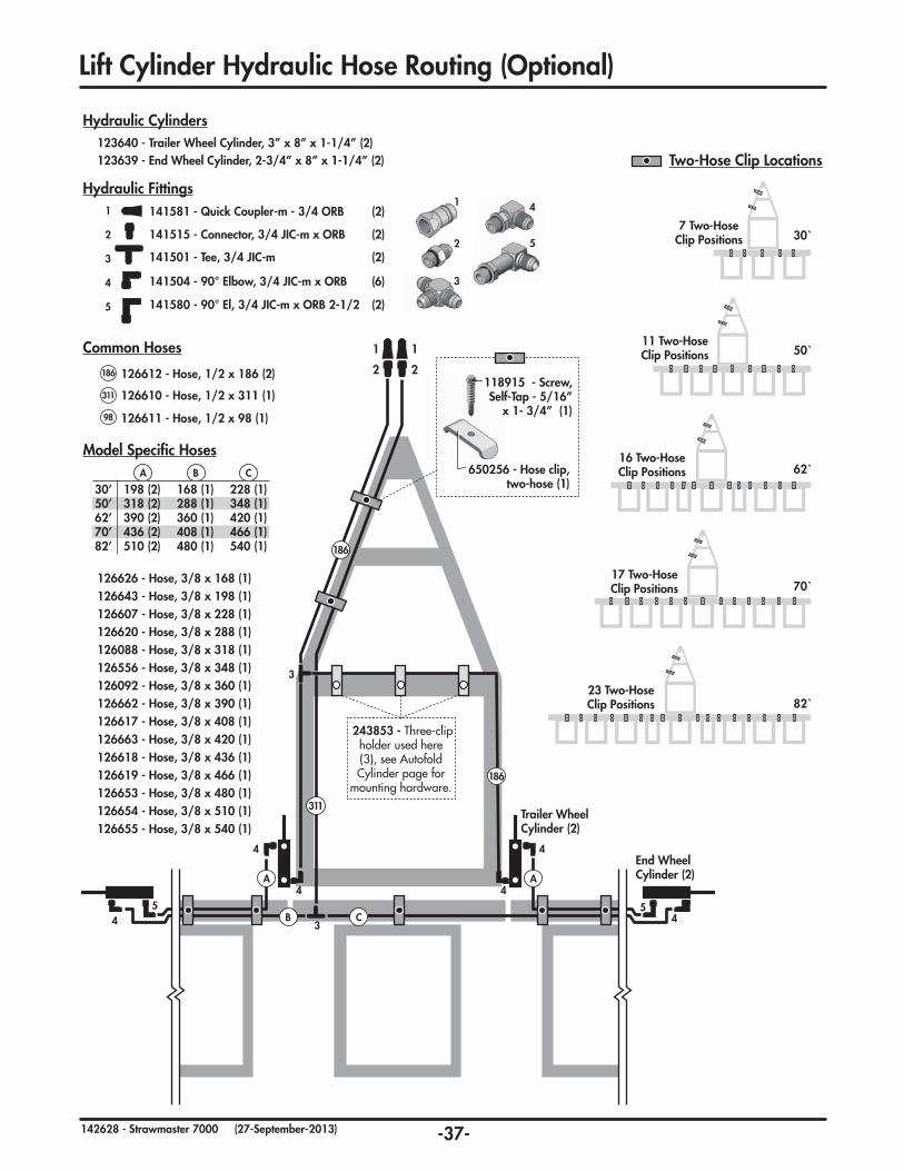
Lift Cylinder Hydraulic Hose Routing (Optional)
3
4
52
1
126611-Hose,1/2x98(1)98
126612-Hose,1/2x186(2)186
311 126610-Hose,1/2x311(1)
Common Hoses
126626-Hose,3/8x168(1)
126088-Hose,3/8x318(1)
126618-Hose,3/8x436(1)
126607-Hose,3/8x228(1)
126619-Hose,3/8x466(1)
126092-Hose,3/8x360(1)
126654-Hose,3/8x510(1)
126643-Hose,3/8x198(1)
126663-Hose,3/8x420(1)
126556-Hose,3/8x348(1)
126653-Hose,3/8x480(1)
126620-Hose,3/8x288(1)
126617-Hose,3/8x408(1)126662-Hose,3/8x390(1)
126655-Hose,3/8x540(1)
Model Specific Hoses
A B C30’ 198 (2) 168 (1) 228 (1)50’ 318 (2) 288 (1) 348 (1)62’ 390 (2) 360 (1) 420 (1)70’ 436 (2) 408 (1) 466 (1)82’ 510 (2) 480 (1) 540 (1)
A CB
3 141501-Tee,3/4JIC-m (2)
4
5
141504-90°Elbow,3/4JIC-mxORB (6)
141580-90°El,3/4JIC-mxORB2-1/2 (2)
2 141515-Connector,3/4JIC-mxORB (2)
1 141581-QuickCoupler-m-3/4ORB (2)
Hydraulic Fittings
123640-TrailerWheelCylinder,3”x8”x1-1/4”(2)123639-EndWheelCylinder,2-3/4”x8”x1-1/4”(2)
Hydraulic Cylinders
30`
23 Two-HoseClip Positions
17 Two-HoseClip Positions
16 Two-HoseClip Positions
11 Two-HoseClip Positions
7 Two-HoseClip Positions
50`
62`
70`
82`
Two-Hose Clip Locations
11
22
186
311
186
A A
CB
Trailer Wheel Cylinder (2)
End Wheel Cylinder (2)
3
34 45 5
4 4
4 4
243853 - Three-clip holder used here (3), see Autofold Cylinder page for
mounting hardware.
118915 - Screw, Self-Tap-5/16”
x1-3/4”(1)
650256 - Hose clip, two-hose (1)

-38-142628 - Strawmaster 7000 (27-September-2013)
Degelman Monarch Hydraulic Cylinder Cylinder# Cylinder# Description 123225 122120 2-1/2”x8x1-1/8“R” 123226 122130 2-3/4”x8x1-1/8“R” 122830 122140 3”x8x1-1/4“R” 122836 122150 3-1/4”x8x1-1/4“R” 122850 122160 3-1/2”x8x1-1/4”R” 123258 122170 3-3/4”x8x1-3/8“R” 123275 122180 4”x8x1-3/8“R”
Rephasing CylindersNote: Smallest Cylinder (2-1/2”) is always located on far left harrow section. The cylinder size gets progressively larger to the right. Larger Strawmasters require more cylinders as shown below.
4
2
6
1
650ft
588
258
466
2-1/2
2-3/4
23
222
666 6
1
6 4462ft
660
212258
2-1/2
2-3/4
3
23
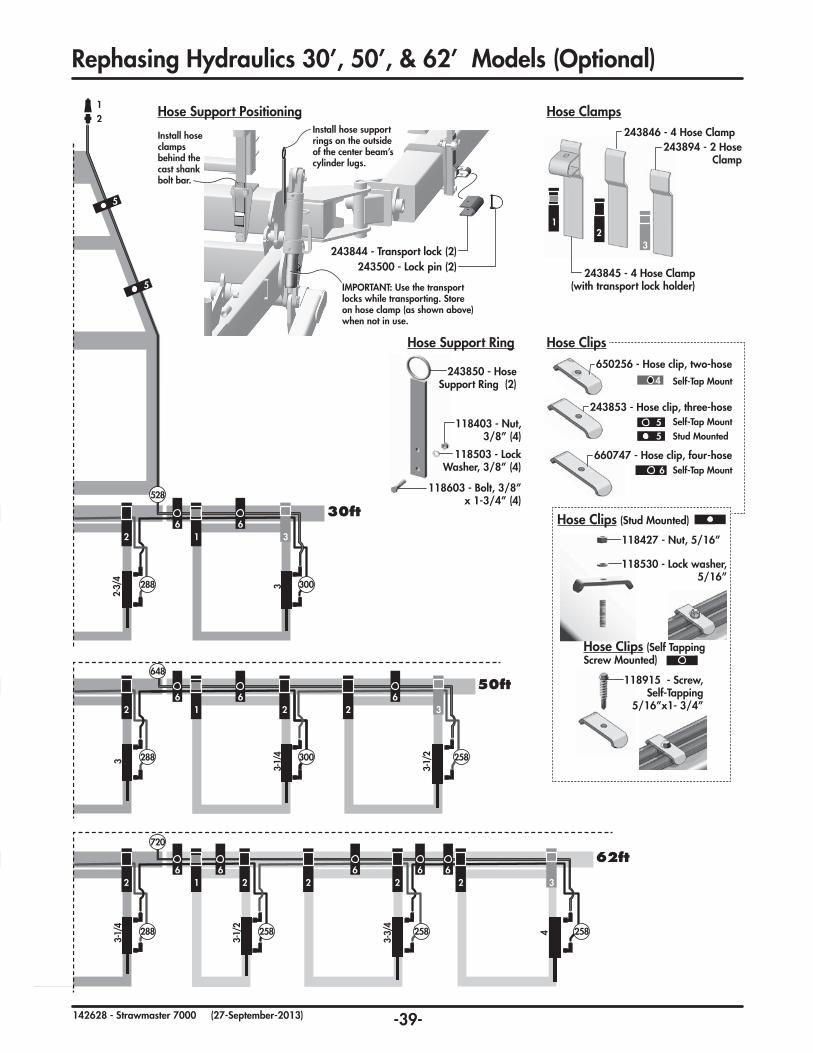
RephasingHydraulics30’,50’,&62’Models(Optional)
4
1
6
2
430ft
466
5
5
2-1/2
12
30ft
50ft
62ft
3
2
1
3 141504-90°Elbow,3/4JIC-mxORB
2 141515-Connector,3/4JIC-mxORB
1 141581-QuickCoupler-m-3/4ORB
Hydraulic FittingsNote: Numbers vary depending on the number of rephasing hydarulic cylinders.
126623-Hose,3/8x212
126619-Hose,3/8x466
126620-Hose,3/8x288
126087-Hose,3/8x588
126080-Hose,3/8x258
126664-Hose,3/8x720
126085-Hose,3/8x528
126604-Hose,3/8x300
126631-Hose,3/8x660126089-Hose,3/8x648
Hydraulic HosesNote: Part numbers for replacement hoses are listed below. Please refer to the diagram specific to your model to identify required hose(s).
2-1/2”Centered
36”
-39-142628 - Strawmaster 7000 (27-September-2013)
5
5
26 6
31
30ft528
288 300
2-3/4
3
RephasingHydraulics30’,50’,&62’Models(Optional)
26 6 6 6 6
2 2 2 2 31
62ft
288 258 258 258
720
3-1/4
4
3-1/2
3-3/4
26 6 6
2 2 31
50ft
288 300 258
648
3-1/4
3-1/2
312
243844 - Transport lock (2)
Install hose support rings on the outside of the center beam’s cylinder lugs.
Install hose clamps behind the cast shank bolt bar.
243500 - Lock pin (2)
Hose Support Positioning
IMPORTANT: Use the transport locks while transporting. Store onhoseclamp(asshownabove)when not in use.
3
12
Hose Clamps
243845 - 4 Hose Clamp(with transport lock holder)
243846 - 4 Hose Clamp243894 - 2 Hose
Clamp
243850 - Hose Support Ring (2)
118603-Bolt,3/8”x1-3/4”(4)
118503 - Lock Washer,3/8”(4)
118403 - Nut, 3/8”(4)
Hose Support Ring650256 - Hose clip, two-hose
Self-Tap Mount4
6
660747 - Hose clip, four-hoseSelf-Tap Mount
243853 - Hose clip, three-hoseSelf-Tap MountStud Mounted
55
Hose Clips
Hose Clips (Self Tapping Screw Mounted)
118915 - Screw, Self-Tapping
5/16”x1-3/4”
118530 - Lock washer, 5/16”
Hose Clips (Stud Mounted)
118427-Nut,5/16”

-40-142628 - Strawmaster 7000 (27-September-2013)
Degelman Monarch Hydraulic Cylinder Cylinder# Cylinder# Description 123225 122120 2-1/2”x8x1-1/8“R” 123226 122130 2-3/4”x8x1-1/8“R” 122830 122140 3”x8x1-1/4“R” 122836 122150 3-1/4”x8x1-1/4“R” 122850 122160 3-1/2”x8x1-1/4”R” 123258 122170 3-3/4”x8x1-3/8“R” 123275 122180 4”x8x1-3/8“R” 123278 122190 4-1/4”x8x1-1/2“R” 123300 122195 4-1/2”x8x1-1/2“R”
Rephasing CylindersNote: Smallest Cylinder (2-1/2”) is always located on far left harrow section. The cylinder size gets progressively larger to the right. Larger Strawmasters require more cylinders as shown below.
222 166644
70ft708
258258
5
5
4
2-1/2
62
12
3 3 3
3 3 3
3
2-3/4
3
3
3-1/4
22222 1666666
82ft 780
212258258
462
2-1/2
2-3/4
3333
3333
6
RephasingHydraulics70’&82’Models(Optional)
70ft
82ft3
2
1
3 141504-90°Elbow,3/4JIC-mxORB
2 141515-Connector,3/4JIC-mxORB
1 141581-QuickCoupler-m-3/4ORB
Hydraulic FittingsNote: Numbers vary depending on the number of rephasing hydarulic cylinders.
126623-Hose,3/8x212
126081-Hose,3/8x708
126620-Hose,3/8x288
126096-Hose,3/8x780
126080-Hose,3/8x258
126082-Hose,3/8x768
126604-Hose,3/8x300
126084-Hose,3/8x840
Hydraulic HosesNote: Part numbers for replacement hoses are listed below. Please refer to the diagram specific to your model to identify required hose(s).
2-1/2”Centered
36”

-41-142628 - Strawmaster 7000 (27-September-2013)
2 2 2 2 2 2 316 6 6 6 6 6 6
288 258 258 258 258
840 82ft
4
4-1/4
4-1/2
3-1/2
3-3/4
2
33333
33333
6
243850 - Hose Support Ring (2)
118603-Bolt,3/8”x1-3/4”(4)
118503 - Lock Washer,3/8”(4)
118403 - Nut, 3/8”(4)
Hose Support Ring
RephasingHydraulics70’&82’Models(Optional)
2 2 2 2 2 316 6 6 6 6
70ft
3-1/4
4
3-1/2
3-3/4
12
5
5
3 3 3 3
3 3 3 3288 300 258 258
768
650256 - Hose clip, two-hoseSelf-Tap Mount4
6
660747 - Hose clip, four-hoseSelf-Tap Mount
243853 - Hose clip, three-hoseSelf-Tap MountStud Mounted
55
Hose Clips
243844 - Transport lock (2)
Install hose support rings on the outside of the center beam’s cylinder lugs.
Install hose clamps behind the cast shank bolt bar.
243500 - Lock pin (2)
Hose Support Positioning
IMPORTANT: Use the transport locks while transporting. Store onhoseclamp(asshownabove)when not in use.
3
12
Hose Clamps
243845 - 4 Hose Clamp(with transport lock holder)
243846 - 4 Hose Clamp243894 - 2 Hose
Clamp
Hose Clips (Self Tapping Screw Mounted)
118915 - Screw, Self-Tapping
5/16”x1-3/4”
118530 - Lock washer, 5/16”
Hose Clips (Stud Mounted)
118427-Nut,5/16”

-42-142628 - Strawmaster 7000 (27-September-2013)
12345
6789
10
GREEN #1
RED #3
BLACK #2
WHITE #4
FROM 7 POLE PLUG
GREEN #6
WHITE SPLICE #8
GREEN #9
WHITE SPLICE #8
BLACK SPLICE #7
BLACK SPLICE #7TO RH TAIL LIGHT
TO LH TAIL LIGHT
Use 60% tin 40% lead rosin solder.
a terminal then twist together If more than one wire goes into before inserting into terminal.
and solder to prevent fraying.
Note: Twist & solder all ends
GREEN - GREEN
BROWN - RED
WHITE - BLACK
YELLOW - WHITE
7 POLE PLUGTO J-BOX
GREEN
WHITE
BROWN
YELLOW
RH LIGHT PLUG
LH LIGHT PLUG
GREEN - RED (Amber light)
WHITE - BROWN (Red light)
GREEN - RED (Amber light)
WHITE - BROWN (Red light)
BLACK - WHITE (Ground)
BLACK - WHITE (Ground)RH FROM J-BOX
LH FROM J-BOX
CONNECT WIRE # TO TERMINAL BLOCK #
244115-Wire,16/4Super VU - 17ft (1)
129027 - Plug, 7 Pole (1)
To Junction
Box
ELECTRICAL CONNECTION PLUG, 7 POLE
Tie
Tie
Tie Tie to HydraulicHoses, 3 Places
9”
12345
6789
10
GREEN #1
RED #3
BLACK #2
WHITE #4
FROM 7 POLE PLUG
GREEN #6
WHITE SPLICE #8
GREEN #9
WHITE SPLICE #8
BLACK SPLICE #7
BLACK SPLICE #7TO RH TAIL LIGHT
TO LH TAIL LIGHT
Use 60% tin 40% lead rosin solder.
a terminal then twist together If more than one wire goes into before inserting into terminal.
and solder to prevent fraying.
Note: Twist & solder all ends
GREEN - GREEN
BROWN - RED
WHITE - BLACK
YELLOW - WHITE
7 POLE PLUGTO J-BOX
GREEN
WHITE
BROWN
YELLOW
RH LIGHT PLUG
LH LIGHT PLUG
GREEN - RED (Amber light)
WHITE - BROWN (Red light)
GREEN - RED (Amber light)
WHITE - BROWN (Red light)
BLACK - WHITE (Ground)
BLACK - WHITE (Ground)RH FROM J-BOX
LH FROM J-BOX
CONNECT WIRE # TO TERMINAL BLOCK #
Note: Twist and solder all ends before inserting into terminal. If more than one wire goes into a terminal - twist together and solder to prevent fraying. (Use 60% tin 40% lead rosin solder.)
ELECTRICAL JUNCTION BOX
244105 - Junction box (1)
129035 - Terminal Strip, 5 Connection (1)
118735-Screw,1/4x 1 - Self Tap (2)
118588-Washer,Rubber-3/16(2)118716-Screw,#8x3/4(2)
118717-LockNut,1/2NPT(3)
From 7 Pole Plug
Wire,16/3SuperVU-LH (1) 244123 - 59ft (82ft SM) 244114 - 53ft (70ft SM) 244126 - 48ft (62ft SM) 244113 - 42ft (50ft SM) 244112 - 32ft (30ft SM)
Wire,16/3SuperVU-RH (1) 244114 - 53ft (82ft SM) 244111 - 46ft (70ft SM) 244113 - 42ft (62ft SM) 244110 - 36ft (50ft SM) 244109 - 26ft (30ft SM)
129033 - Straight Cord Connector (3)
12345
6789
10
GREEN #1
RED #3
BLACK #2
WHITE #4
FROM 7 POLE PLUG
GREEN #6
WHITE SPLICE #8
GREEN #9
WHITE SPLICE #8
BLACK SPLICE #7
BLACK SPLICE #7TO RH TAIL LIGHT
TO LH TAIL LIGHT
Use 60% tin 40% lead rosin solder.
a terminal then twist together If more than one wire goes into before inserting into terminal.
and solder to prevent fraying.
Note: Twist & solder all ends
GREEN - GREEN
BROWN - RED
WHITE - BLACK
YELLOW - WHITE
7 POLE PLUGTO J-BOX
GREEN
WHITE
BROWN
YELLOW
RH LIGHT PLUG
LH LIGHT PLUG
GREEN - RED (Amber light)
WHITE - BROWN (Red light)
GREEN - RED (Amber light)
WHITE - BROWN (Red light)
BLACK - WHITE (Ground)
BLACK - WHITE (Ground)RH FROM J-BOX
LH FROM J-BOX
CONNECT WIRE # TO TERMINAL BLOCK #Tailight Wiring
Connection129042 - Clamp, Rubber Cushion,3/8(6)
244120-Grommet,5/8x5/8(2)
129043 - Crimp, Butt Splice - 16
gauge (6)
129022 - Triplug Wire, 18 (2)
129041-Grommet,3/8x1/4(2)
244108 - Split Loom,3/8x39-1/2(2)118735 - Screw,
1/4-20x3/4(6)
Note: Strip insulation 3/4” then fold wire over before inserting into crimp splice.
TAILIGHT WIRING CONNECTION
129020 - Dual Lamp (RH) (1)129021 - Dual Lamp (LH) (1)
PreviousDualLamps
ElectricalComponents&Routing(Previous)
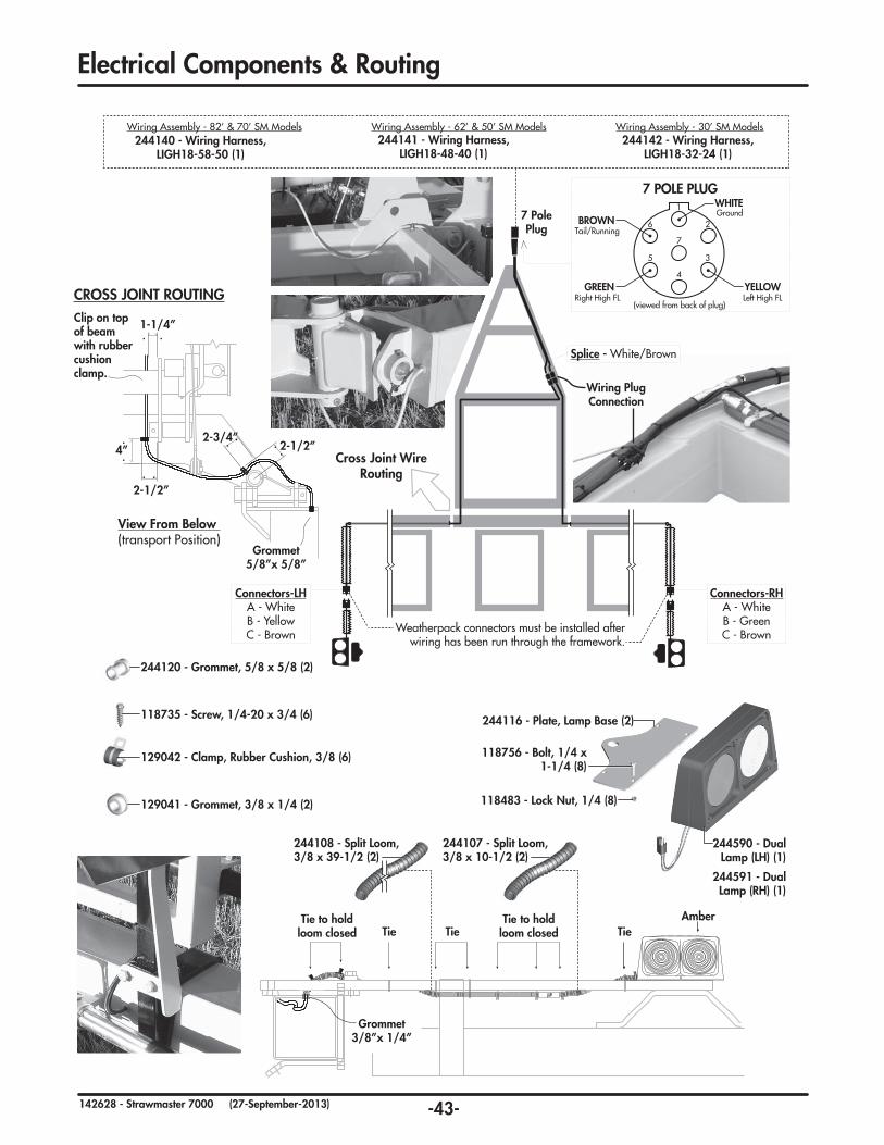
-43-142628 - Strawmaster 7000 (27-September-2013)
244591 - Dual Lamp (RH) (1)
244590 - Dual Lamp (LH) (1)
244116 - Plate, Lamp Base (2)
118756-Bolt,1/4x1-1/4(8)
118483-LockNut,1/4(8)
ElectricalComponents&Routing
244107 - Split Loom, 3/8x10-1/2(2)
Tie to hold loom closed
Tie to hold loom closedTie Tie Tie
Amber
Grommet3/8”x1/4”
View From Below (transport Position)
Clip on top of beam with rubber cushion clamp.
1-1/4”
2-1/2”
2-1/2”2-3/4”
4”
Grommet5/8”x5/8”
CROSS JOINT ROUTING
Wiring Plug Connection
Cross Joint Wire Routing
244108 - Split Loom, 3/8x39-1/2(2)
129042-Clamp,RubberCushion,3/8(6)
129041-Grommet,3/8x1/4(2)
244120-Grommet,5/8x5/8(2)
118735-Screw,1/4-20x3/4(6)
7 POLE PLUG
(viewed from back of plug)
Ground
Tail/Running
Right High FL Left High FLGREEN
WHITE
BROWN
YELLOW
1
7
4
5 3
6 2
Weatherpack connectors must be installed after wiring has been run through the framework.
Connectors-LHA - WhiteB - YellowC - Brown
Connectors-RHA - WhiteB - GreenC - Brown
Splice - White/Brown
244140 - Wiring Harness, LIGH18-58-50 (1)
Wiring Assembly - 82’ & 70’ SM Models244141 - Wiring Harness,
LIGH18-48-40 (1)
Wiring Assembly - 62’ & 50’ SM Models244142 - Wiring Harness,
LIGH18-32-24 (1)
Wiring Assembly - 30’ SM Models
7 Pole Plug

-44-142628 - Strawmaster 7000 (27-September-2013)
2 YearLimited Warranty - Agricultural Products
Degelman Industries Ltd. (“Degelman”) warrants to the original purchaser of any new Degelman equipment, purchased from an authorized Degelman dealer, that the equipment will be free from defects in material and workmanship for a period of two (2) years from the date of delivery, for non-commercial use (including farm, institutional, government, and municipality) and (1) year from the date of delivery for commercial use. The obligation of Degelman to the purchaser under this warranty is limited to the repair or replacement of defective parts in the first year and to the provision, but not the installation of replacement parts in the second year. Degelman reserves the right to inspect any equipment or parts which are claimed to have been defective in material or workmanship.
This warranty limits its replacement or repair coverage to what is consistent with the warranty of Degelman’s suppliers of purchased components.
Replacement or repair parts installed in the equipment covered by this limited warranty are warranted for ninety (90) days from the date of delivery of such part or the expiration of the applicable new equipment warranty period, which ever occurs later. Warranted parts shall be provided at no cost to the user at an authorized Degelman dealer during regular working hours. Warranted replacement parts will either be replaced or rebuilt at Degelman’s discretion.
Disclaimer of implied warranties & consequential damages
This warranty shall not be interpreted to render Degelman Industries Ltd. liable for injury, death, property damage or damages of any kind, whether direct, consequential, or contingent to property. Without limiting the generality of the foregoing, Degelman shall not be liable for damages resulting from any cause beyond its reasonable control, including, without limitation, loss of crops, any expense or loss of labour, supplies, rental machinery or loss of use.
No other warranty of any kind whatsoever, express or implied is made with respect to this sale; and all implied warranties of merchantability and fitness for a particular purpose which exceed the obligations set forth in this written warranty are hereby disclaimed and excluded from this sale. This exclusion shall not apply in any jurisdiction where it is not permitted by law.
This limited warranty shall not apply:
1. If, in the sole opinion of Degelman, the unit has been subjected to misapplication, abuse, misuse, negligence accident or incorrect off-site machine set-up.
2. To any goods that have sustained damage or deterioration attributable to a lack of routine maintenance (eg. Check and Re-torque of fastening hardware, Hydraulic fluid purities, drive train alignments, and clutch operation)
3. If parts not made or supplied by Degelman have been used in the connection with the unit, if, in the sole judgement of Degelman such use affects its performance, safety, stability or reliability.
4. If the unit has been altered or repaired outside of an authorized Degelman dealership in a manner which, in the sole judgement of Degelman, affects its performance, safety, stability or reliability.
5. To expendable or wear items such as (eg. Harrow tines, Rock Picker and Rock Rake wear teeth and replaceable bushings and pins.) and any other items that in the company’s sole judgement are a wear item.
No employee or representative of Degelman Industries Ltd. is authorized to change this limited warranty in any way or grant any other warranty unless such change is made in writing and signed by the Degelman Service Manager.
This limited warranty is subject to any future availability of supply, which may directly affect Degelman’s ability to obtain materials or manufacture replacement parts.
Degelman reserves the right to make improvements in design or changes in specifications at any time, without incurring obligations to owners of equipment previously delivered.
This limited warranty is subject to compliance by the customer to the enclosed Retail Customer’s Responsibility Under Degelman Warranty.
Warranty
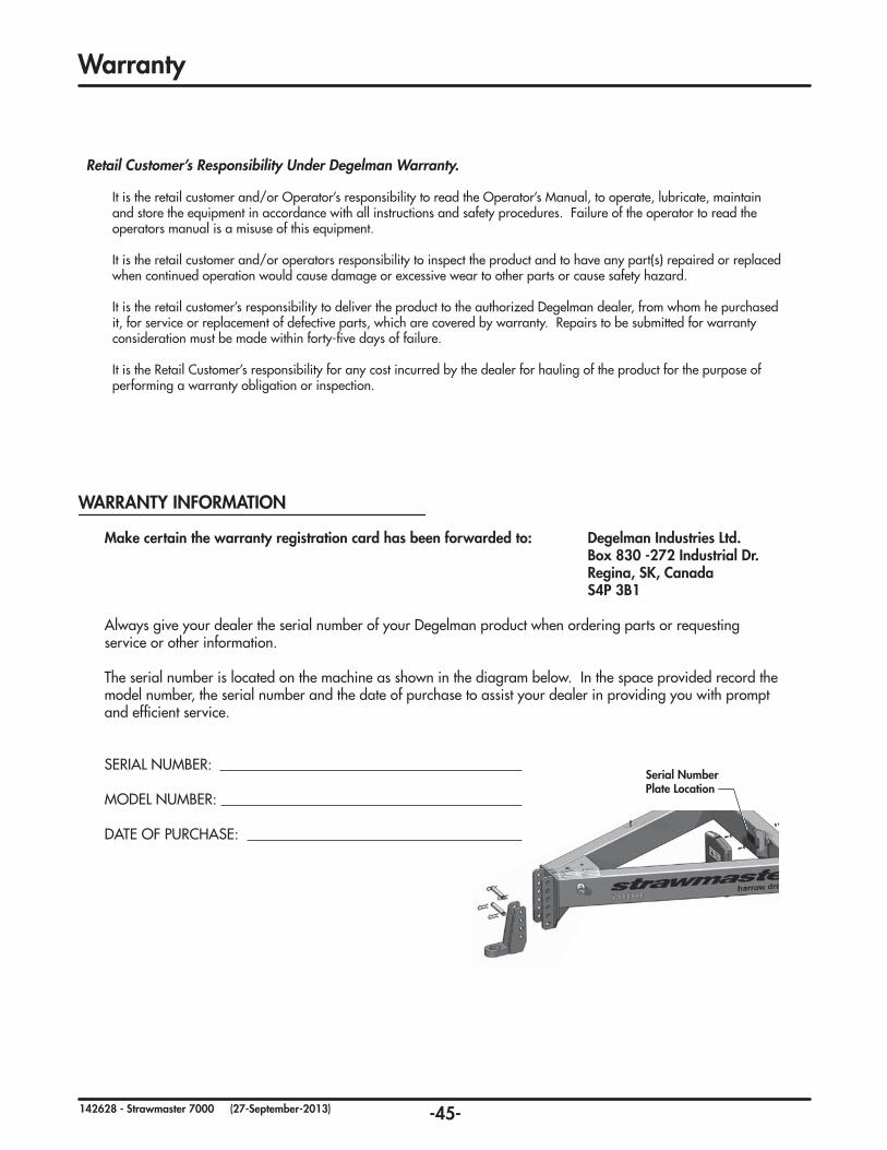
-45-142628 - Strawmaster 7000 (27-September-2013)
Serial Number Plate Location
Warranty
Make certain the warranty registration card has been forwarded to: Degelman Industries Ltd. Box 830 -272 Industrial Dr. Regina,SK,Canada S4P 3B1
Always give your dealer the serial number of your Degelman product when ordering parts or requesting service or other information.
The serial number is located on the machine as shown in the diagram below. In the space provided record the model number, the serial number and the date of purchase to assist your dealer in providing you with prompt and efficient service.
SERIAL NUMBER:
MODEL NUMBER:
DATE OF PURCHASE:
WARRANTY INFORMATION
Retail Customer’s Responsibility Under Degelman Warranty.
It is the retail customer and/or Operator’s responsibility to read the Operator’s Manual, to operate, lubricate, maintain and store the equipment in accordance with all instructions and safety procedures. Failure of the operator to read the operators manual is a misuse of this equipment.
It is the retail customer and/or operators responsibility to inspect the product and to have any part(s) repaired or replaced when continued operation would cause damage or excessive wear to other parts or cause safety hazard.
It is the retail customer’s responsibility to deliver the product to the authorized Degelman dealer, from whom he purchased it, for service or replacement of defective parts, which are covered by warranty. Repairs to be submitted for warranty consideration must be made within forty-five days of failure.
It is the Retail Customer’s responsibility for any cost incurred by the dealer for hauling of the product for the purpose of performing a warranty obligation or inspection.