operator manual - greatplainsag.com · check tractor capacity and configuration ... 2017-10-30...
TRANSCRIPT

Table of Contents Index
Operator ManualDiscovator (Disc & Coulter)
Series VIII 8321, 8324, 8326, 8328,8333, 8537, 8544, 8548 & 8552
Manufacturing, Inc.www.greatplainsmfg.com
Read the operator’s manual entirely. When you see this symbol, thesubsequent instructions and warnings are serious - follow withoutexception. Your life and the lives of others depend on it!
Illustrations may show optional equipment not supplied with standard unit.
41419
© Copyright 2017 Printed 2017-10-30 550-353M
EN
Table of Contents Index
ORIGINAL INSTRUCTIONS

Table of Contents Index
Table of Contents Index

8321-8552DV Cover Index Table of Contents iii
Table of Contents
Important Safety Information.................................................1Safety Decals ....................................................................5
Introduction..........................................................................10Models Covered ..............................................................10Description of Unit ...........................................................10
Document Family .....................................................10Using This Manual...........................................................10
Definitions.................................................................10Owner Assistance............................................................11
Further Assistance ...................................................11Preparation and Setup .........................................................12
Prior to Going to the Field Checklist ................................12Hitching Tractor to Discovator .........................................13
Hydraulic Hose Hookup............................................14Hose Handles...........................................................14
First Time Field Adjustments ...........................................14Pre-Leveling of Machine 14Front to Rear Leveling..............................................14Side to Side Leveling................................................15Setting Gauge Wheels .............................................15Disc Gang Depth Calibration....................................16Field Operation of Disc Gangs .................................16
Operating Instructions .........................................................18Pre-Start Checklist...........................................................18Transporting ....................................................................18
Check Tractor Capacity and Configuration ..............18Transport Checklist ..................................................18
General Operation and In-Field Adjustments ..................19Scraper Settings..............................................................19Rear Attachment Settings ...............................................19
Spike Drag Settings .................................................19HD Spike & Reel Settings ........................................20Coil Tine Settings .....................................................20Reel Settings............................................................20
Maintenance and Lubrication..............................................21Maintenance....................................................................21Lubrication.......................................................................21
Wheel Bearing Hub ..................................................21Inside Wing Hinge Points .........................................22Outside Wing Hinge Points ......................................22Walking Beam Pivot Bearings..................................22
Troubleshooting ...................................................................23Discovator Trouble Shooting Charts ...............................23
Appendix ...............................................................................26DV Specifications and Capacities ...................................26Tire Inflation and Warranty ..............................................26Hydraulic Connectors and Torque...................................27Torque Values Chart .......................................................28Warranty..........................................................................29
2017-10-30 Cover Index 550-353M
© Copyright 2006, 2007, 2008, 2009, 2010, 2011, 2012, 2013, 2014, 2015, 2016, 2017 All rights Reserved
Great Plains Manufacturing, Inc. provides this publication “as is” without warranty of any kind, either expressed or implied. While every precaution has beentaken in the preparation of this manual, Great Plains Manufacturing, Inc. assumes no responsibility for errors or omissions. Neither is any liability assumedfor damages resulting from the use of the information contained herein. Great Plains Manufacturing, Inc. reserves the right to revise and improve its productsas it sees fit. This publication describes the state of this product at the time of its publication, and may not reflect the product in the future.
Trademarks of Great Plains Manufacturing, Inc. include: AccuShot, Max-Chisel, Row-Pro, Singulator Plus, Short Disk, Swath Command, Terra-Tine, Ultra-Chisel, and X-Press.
Registered Trademarks of Great Plains Manufacturing, Inc. include: Air-Pro, Clear-Shot, Discovator, Great Plains, Land Pride, MeterCone, Nutri-Pro, Seed-Lok, Solid Stand, Terra-Guard, Turbo-Chisel, Turbo-Chopper, Turbo-Max, Turbo-Till, Ultra-Till, Whirlfilter, and Yield-Pro.
Brand and Product Names that appear and are owned by others are trademarks of their respective owners.Printed in the United States of America

8321-8552DV Table of Contents Index iv
2017-10-30 Table of Contents Index 550-353M

8321-8552DV Table of Contents Index Important Safety Information 1
Important Safety Information
Look for Safety SymbolThe SAFETY ALERT SYMBOL indicates there is apotential hazard to personal safety involved and extrasafety precaution must be taken. When you see thissymbol, be alert and carefully read the message thatfollows it. In addition to design and configuration ofequipment, hazard control and accident prevention aredependent upon the awareness, concern, prudence andproper training of personnel involved in the operation,transport, maintenance and storage of equipment.
Be Aware of Signal WordsSignal words designate a degree or level of hazardseriousness.
DANGER indicates an imminently hazardous situationwhich, if not avoided, will result in death or serious injury.This signal word is limited to the most extreme situations,typically for machine components that, for functionalpurposes, cannot be guarded.
WARNING indicates a potentially hazardous situationwhich, if not avoided, could result in death or seriousinjury, and includes hazards that are exposed whenguards are removed. It may also be used to alert againstunsafe practices.
CAUTION indicates a potentially hazardous situationwhich, if not avoided, may result in minor or moderateinjury. It may also be used to alert against unsafepractices.
Prepare for Emergencies Be prepared if a fire starts
Keep a first aid kit and fire extinguisher handy.
Keep emergency numbers for doctor, ambulance, hospitaland fire department near phone.
Be Familiar with Safety Decals Read and understand “Safety Decals” on page 5,
thoroughly.
Read all instructions noted on the decals.
Keep decals clean. Replace damaged, faded and illegibledecals.
2017-10-30 Table of Contents Index 550-353M

8321-8552DV Table of Contents Index Important Safety Information 2
Wear Protective Equipment Wear protective clothing and equipment.
Wear clothing and equipment appropriate for the job.Avoid loose-fitting clothing.
Because prolonged exposure to loud noise can causehearing impairment or hearing loss, wear suitablehearing protection such as earmuffs or earplugs.
Because operating equipment safely requires your fullattention, avoid wearing entertainment headphones whileoperating machinery.
Handle Chemicals ProperlyAgricultural chemicals can be dangerous. Improper usecan seriously injure persons, animals, plants, soil andproperty.
Read and follow chemical manufacturer’s instructions.
Wear protective clothing.
Handle all chemicals with care.
Avoid inhaling smoke from any type of chemical fire.
Store or dispose of unused chemicals as specified bychemical manufacturer.
Avoid High Pressure FluidsEscaping fluid under pressure can penetrate the skin,causing serious injury.
Avoid the hazard by relieving pressure beforedisconnecting hydraulic lines.
Use a piece of paper or cardboard, NOT BODY PARTS, tocheck for suspected leaks.
Wear protective gloves and safety glasses or goggles whenworking with hydraulic systems.
If an accident occurs, seek immediate medical assistancefrom a physician familiar with this type of injury.
Use Safety Lights and DevicesSlow-moving tractors and towed implements can createa hazard when driven on public roads. They are difficultto see, especially at night.
Use flashing warning lights and turn signals wheneverdriving on public roads.
Use lights and devices provided with implement
Keep Riders Off MachineryRiders obstruct the operator’s view. Riders could bestruck by foreign objects or thrown from the machine.
Never allow children to operate equipment.
Keep all bystanders away from machine during operation.
2017-10-30 Table of Contents Index 550-353M

8321-8552DV Table of Contents Index Important Safety Information 3
Transport Machinery SafelyMaximum transport speed for implement is 20 mph (32kph), 13 mph (22 kph) in turns. Some rough terrainsrequire a slower speed. Sudden braking can cause atowed load to swerve and upset.
Do not exceed 20 mph. Never travel at a speed which doesnot allow adequate control of steering and stopping.Reduce speed if towed load is not equipped with brakes.
Comply with state and local laws.
Do not tow an implement that, when fully loaded, weighsmore than 1.5 times the weight of towing vehicle.
Carry reflectors or flags to mark Discovator in case ofbreakdown on the road.
Keep clear of overhead power lines and otherobstructions when transporting. Refer to transportdimensions under “DV Specifications and Capacities”on page 26.
Do not fold or unfold the Discovator while the tractor ismoving
Shutdown and Storage Lower Discovator, put tractor in park, turn off engine,
and remove the key.
Secure Discovator using blocks and supports provided.
Detach and store machine in an area where childrennormally do not play.
Tire SafetyTire changing can be dangerous and should beperformed by trained personnel using correct tools andequipment.
When inflating tires, use a clip-on chuck and extensionhose long enough for you to stand to one side–not in frontof or over tire assembly. Use a safety cage if available.
When removing and installing wheels, use wheel-handlingequipment adequate for weight involved.
2017-10-30 Table of Contents Index 550-353M
8321-8552DV Table of Contents Index Important Safety Information 4
Practice Safe Maintenance Understand procedure before doing work. Use proper
tools and equipment. Refer to this manual for additionalinformation.
Work in a clean, dry area.
Lower the machine, put tractor in park, turn off engine,and remove key before performing maintenance.
Disconnect battery ground cable (-) before servicing oradjusting electrical systems or before welding onmachine.
Inspect all parts. Make sure parts are in good conditionand installed properly.
Remove buildup of grease, oil or debris.
Remove all tools and unused parts from machine beforeoperation.
Safety At All TimesThoroughly read and understand the instructions in thismanual before operation. Read all instructions noted onthe safety decals.
Be familiar with all machine functions.
Operate machinery from the driver’s seat only.
Do not leave Discovator unattended with tractor enginerunning.
Do not stand between the tractor and machine duringhitching.
Keep hands, feet and clothing away from power-drivenparts.
Wear snug-fitting clothing to avoid entanglement withmoving parts.
Watch out for wires, trees, etc., when folding and raisingmachine. Make sure all persons are clear of working area.
2017-10-30 Table of Contents Index 550-353M
8321-8552DV Table of Contents Index Important Safety Information 5
Safety DecalsSafety Reflectors and DecalsYour implement comes equipped with all lights, safetyreflectors and decals in place. They were designed tohelp you safely operate your implement.
Read and follow decal directions.
Keep lights in operating condition.
Keep all safety decals clean and legible.
Replace all damaged or missing decals. Order new decalsfrom your Great Plains dealer. Refer to this section forproper decal placement.
When ordering new parts or components, also requestcorresponding safety decals.
To install new decals:
1. Clean the area on which the decal is to be placed.
2. Peel backing from decal. Press firmly on surface,being careful not to cause air bubbles under decal.
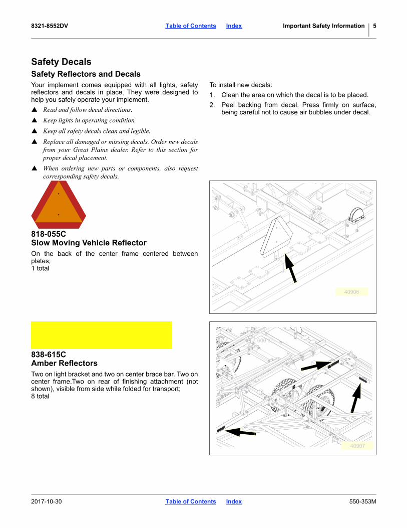
818-055CSlow Moving Vehicle ReflectorOn the back of the center frame centered betweenplates;1 total
40906
838-615CAmber ReflectorsTwo on light bracket and two on center brace bar. Two oncenter frame.Two on rear of finishing attachment (notshown), visible from side while folded for transport;8 total
40907
.tif600 dpi
2017-10-30 Table of Contents Index 550-353M

8321-8552DV Table of Contents Index Important Safety Information 6
838-614CRed ReflectorsOn rear of light brackets (top); On rear of reflectorbracket (top).4 total
41424
.eps
838-603COrange ReflectorsOn rear of light brackets (bottom); On rear of reflectorbracket (bottom).4 total
41424
.eps
838-598CCaution: Read Operator’s ManualOn front of hitch;1 total
40905
2017-10-30 Table of Contents Index 550-353M

8321-8552DV Table of Contents Index Important Safety Information 7
838-599CDanger: Electrocution HazardFront side of center wing brace (left, middle side);1 total
40909
.eps
838-600CDanger: Crushing HazardOn front (middle) of hitch;1 total
40905
838-602CWarning: Overhead Wing HazardOn outside center of center and wing frames (bothsides);4 total 8321,8324, 8326, 8328 & 8333
6 total 8537, 8544, 8548 & 8552
40911
.eps
2017-10-30 Table of Contents Index 550-353M

8321-8552DV Table of Contents Index Important Safety Information 8
838-094CWarning: High Pressure FluidFront side of center wing brace (right, middle side);1 total
40909
.tif600 dpi
838-611CWarning: Hand CrushingFront side of center wing brace (left & right side);2 total
40909
.eps
838-613CNotice: Transport LockOn outside center of center frame (both sides);2 total
.eps
40911
2017-10-30 Table of Contents Index 550-353M

8321-8552DV Table of Contents Index Important Safety Information 9
838-612CWarning: Wings Could Fall SuddenlyOn front of wing stop (both sides);2 total
40910
.eps
838-890CCaution: Tire Pressure and TorqueOn rim of each center transport wheelModels 8548 & 8552;4 total
818-188CWarning: SpeedOn front (middle) of hitch;1 total
40907
818-188C Rev. C
Do Not exceed 20 mph maximum transportspeed. Loss of vehicle control and/or machinecan result.
To Prevent Serious Injury or Death:EXCESSIVE SPEED HAZARD
WARNING
40905
2017-10-30 Table of Contents Index 550-353M

8321-8552DV Table of Contents Index Introduction 10
Introduction
Great Plains welcomes you to our growing family of newproduct owners. The Series VIII Discovator, DV (Disc &Coulter) 8321-8552DV have been designed with careand built by skilled workers using quality materials.Proper setup, maintenance, and safe operating practiceswill help you get years of satisfactory use from themachine.
Models Covered
Description of UnitThe Series VIII Discovator, DV (Disc & Coulter) 8321-8552DV is a three or five-section field finishing, one-passtillage tool. Working width ranges from 21 to 52 feet. Theimplement is designed to combine discing/slicing,cultivating, harrowing and herbicide incorporation in asingle pass. Various finishing attachments are availableto customize your tillage and residue requirements foryour operation.
Document Family
Using This ManualThis manual will familiarize you withsafety, assembly, operation,adjustments, troubleshooting, andmaintenance. Read this manual andfollow the recommendations to helpensure safe and efficient operation.
The information in this manual is current at printing.Some parts may change to assure top performance.
DefinitionsThe following terms are used throughout this manual.
A crucial point of information related to the preceding topic.Read and follow the directions to remain safe, avoid seriousdamage to equipment and ensure desired field results.
Useful information related to the preceding topic.
Right-hand and left-hand as used in this manual are determined by facing the direction the machine will travel while in use unless otherwise stated. An orientation rose in some line art illustrations shows the directions of: Up, Back, Left, Down, Front, Right.
8321DV 21-Foot 3-section
8324DV 24-Foot 3-section
8326DV 26-Foot 3-section
8328DV 28-Foot 3-section
8333DV 33-Foot 3-section
8537DV 37-Foot 5-section
8544DV 44-Foot 5-section
8548DV 48-Foot 5-section
8552DV 52-Foot 5-section
R
LFigure 1
8321DV Discovator41642
U
DF
B
L
R
550-353E Assembly Manual
550-353Q Pre-Delivery Manual
550-353M Operator Manual (this document)
550-353P Parts Manual
U
DF
B
L
R
2017-10-30 Table of Contents Index 550-353M

8321-8552DV Table of Contents Index Introduction 11
Owner AssistanceIf you need customer service or repair parts, contact aGreat Plains dealer. They have trained personnel, repairparts and equipment specially designed for Great Plainsproducts.
Refer to Figure 2
Your machine’s parts were specially designed andshould only be replaced with Great Plains parts. Alwaysuse the serial and model number when ordering partsfrom your Great Plains dealer. The serial-number plate islocated on the left end of the top front tool bar.
Record your 8315/8318/8321/8324DVN Discovatormodel and serial number here for quick reference:
Model Number:__________________________
Serial Number: __________________________
Your Great Plains dealer wants you to be satisfied withyour new machine. If you do not understand any part ofthis manual or are not satisfied with the service received,please take the following actions.
1. Discuss the matter with your dealership servicemanager. Make sure they are aware of any problemsso they can assist you.
2. If you are still unsatisfied, seek out the owner orgeneral manager of the dealership.
Further AssistanceGreat Plains Manufacturing, Inc. wants you to besatisfied with your new Discovator. If for any reason youdo not understand any part of this manual or areotherwise dissatisfies with the product please contact:
Great Plains Service Department1525 E. North St.
PO Box 5060Salina, KS 67402-5060
Or go to www.greatplainsag.com and follow the contact information at the bottom of your screen for our service
department.
Figure 2Serial Number Plate
41134
2017-10-30 Table of Contents Index 550-353M

8321-8552DV Table of Contents Index Preparation and Setup 12
Preparation and Setup
This section helps you prepare your tractor and 8321-8552DV Discovator for use, and covers tasks that needto be done seasonally, or when the tractor/Discovatorconfiguration changes.
Before using the Discovator in the field, you must hitch itto a suitable tractor, inspect systems and level theDiscovator. Before using the Discovator for the first time,and periodically thereafter, certain adjustments andcalibrations are required.
Prior to Going to the Field Checklist
Complete this checklist before routine setup:
Read and understand “Important Safety Information” on page 1.
Check that all working parts are moving freely, bolts are tight, and cotter pins are spread.
Make sure your tractor horsepower matches the implement you are pulling. This is important so the implement can do the best possible job.
Clean all hydraulic couplings and connect to tractor as shown on page 13 and 14.
If machine is folded, remove the transport pins from wing stops. (DO NOT remove pins if the wing is leaning against the pins or putting pressure on the pins. Use the hydraulics to pull the wings in completely before unpinning them.) Once the pins are removed, slowly untold the unit. Make sure no one is under the wings during the unfolding process.
Check again for hydraulic leaks and watch that hoses do not get pinched in hinges, wing stops, etc.
After the machine is completely unfolded, raise and lower the Discovator several times to purge air from the hydraulic system. Again check for hydraulic leaks and tighten or replace if necessary.
Check safety chain hookup. Make sure all warning lights are hooked up and functioning correctly.
Check that all grease fittings are in place and lubricated. See “Lubrication” on page 21. The hubs will come pre-greased and will not need greased at this time.
Check that all safety decals and reflectors are correctly located and legible. Replace if damaged. See “Safety Decals” on page 5.
Inflate tires to pressure recommended and tighten wheel bolts as specified. See “Tire Inflation and Warranty” on page 26.
Put transport locks in place and refold the machine slowly. Put wing stop pins in place. Always use the transport pins when moving from field to field. You are now ready to go to the field.
2017-10-30 Table of Contents Index 550-353M
8321-8552DV Table of Contents Index Preparation and Setup 13
Hitching Tractor to Discovator
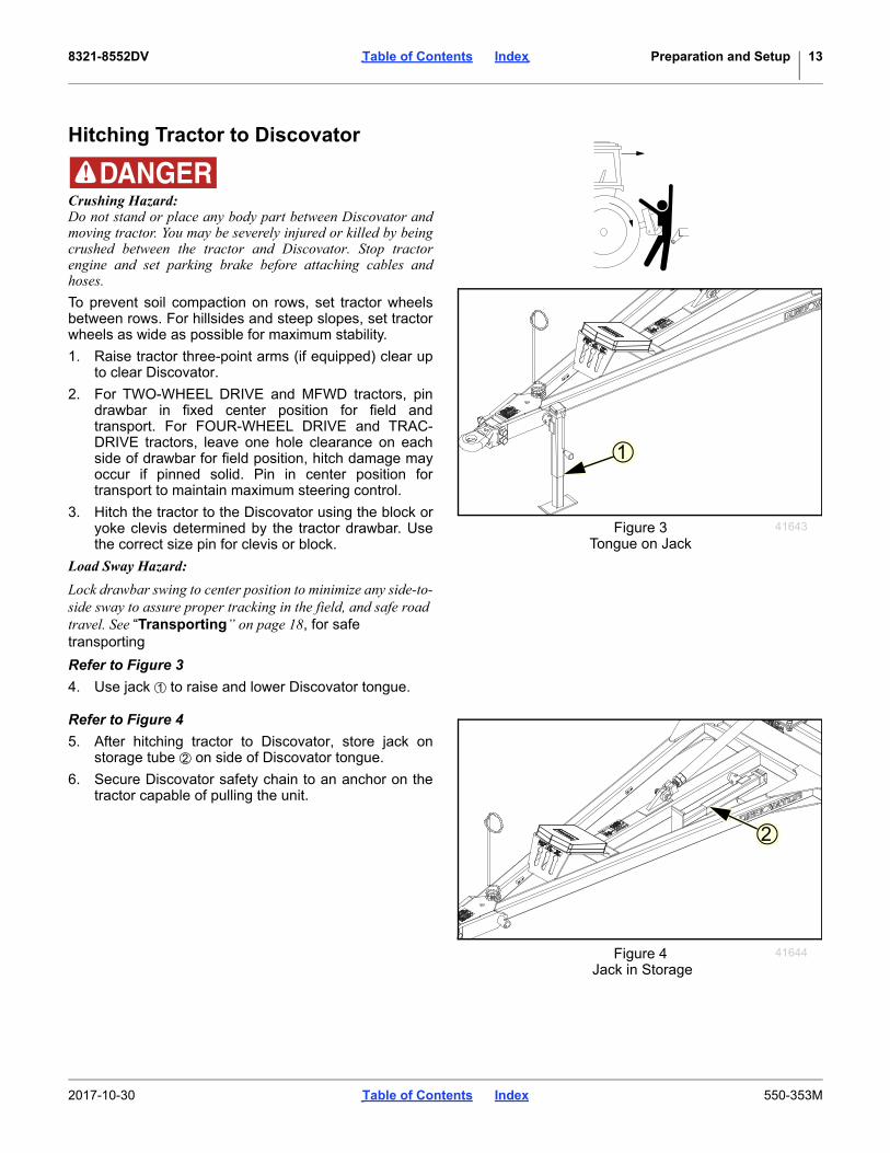
Crushing Hazard:Do not stand or place any body part between Discovator andmoving tractor. You may be severely injured or killed by beingcrushed between the tractor and Discovator. Stop tractorengine and set parking brake before attaching cables andhoses.
To prevent soil compaction on rows, set tractor wheelsbetween rows. For hillsides and steep slopes, set tractorwheels as wide as possible for maximum stability.
1. Raise tractor three-point arms (if equipped) clear upto clear Discovator.
2. For TWO-WHEEL DRIVE and MFWD tractors, pindrawbar in fixed center position for field andtransport. For FOUR-WHEEL DRIVE and TRAC-DRIVE tractors, leave one hole clearance on eachside of drawbar for field position, hitch damage mayoccur if pinned solid. Pin in center position fortransport to maintain maximum steering control.
3. Hitch the tractor to the Discovator using the block oryoke clevis determined by the tractor drawbar. Usethe correct size pin for clevis or block.
Load Sway Hazard:
Lock drawbar swing to center position to minimize any side-to-side sway to assure proper tracking in the field, and safe road travel. See “Transporting” on page 18, for safe transporting
Refer to Figure 3
4. Use jack to raise and lower Discovator tongue.
Refer to Figure 4
5. After hitching tractor to Discovator, store jack onstorage tube on side of Discovator tongue.
6. Secure Discovator safety chain to an anchor on thetractor capable of pulling the unit.
Figure 3Tongue on Jack
41643
1
1
Figure 4 Jack in Storage
41644
2
2
2017-10-30 Table of Contents Index 550-353M

8321-8552DV Table of Contents Index Preparation and Setup 14
Hydraulic Hose HookupGreat Plains hydraulic hoses are color coded to help youhookup hoses to your tractor outlets. Hoses that go tothe same remote valve are marked with the same color.
Refer to Figure 5
Hose HandlesTo distinguish hoses on the same hydraulic circuit, referto, “Hydraulic Hose Hookup” on page 14. The hoseunder an extended symbol feeds a cylinder base end.The hose under a retracted-cylinder symbol feeds acylinder rod end.
Clean all hydraulic couplings and hook hoses to tractor.
First Time Field AdjustmentsPre-Leveling of Machine
Front to Rear LevelingRefer to Figure 6
1. Pre-leveling of machine can be done on a concreteslab or level surface. Lower machine so sweeps are2-3” off of ground on the center frame. Adjustturnbuckle at the front of machine to level it fromfront to back. (Shorten to bring front down, extend tobring front up). Level machine with the front row justslightly deeper or lower than the back.
Color Hydraulic Function
Black Lift (2 hoses)
Green Fold (2 hoses)
Red Gang (2 hoses)
High Pressure Fluid Hazard:Relieve pressure before disconnecting hydraulic lines. Usepaper or cardboard, NOT BODY PARTS, to check for leaks.Wear protective gloves and safety glasses or goggles whenworking with hydraulic systems. Escaping fluid under pressurecan have sufficient pressure to penetrate the skin causingserious injury. If an accident occurs, seek immediate medicalassistance from a physician familiar with this type of injury.Only trained personnel should work on system hydraulics.
Figure 5 Hose Handles
41552
Figure 6Hitch Turnbuckle Adjustment
41598
2017-10-30 Table of Contents Index 550-353M

8321-8552DV Table of Contents Index Preparation and Setup 15
Side to Side LevelingRefer to Figure 7
2. Set the wings to match the depth of the center. This is done by adjusting the lift cylinder eyebolt on each wing. Lengthen the bolt to run shallower, shorten the bolt to run deeper.
Setting Gauge WheelsRefer to Figure 8
3. Once the machine has been adjusted and set to thedesired working depth, you may now adjust thegauge wheels.
The gauge wheels (if equipped) should be set in fieldposition to be 12” to 112” off the ground.
4. To adjust the gauge wheels you will need to loosenthe 2 bolts on the side of the gauge wheel bracket ,and removed the hitch pin and adjust the gaugewheel arm up or down till it is 12” - 112” off theground and replace the hitch pin and cotter key. Re-tighten the bolts.
With the manual gauge wheels anytime the depth ofthe machine is adjusted you must adjust the gaugewheels following the steps listed above.
Refer to Figure 9
5. Once the machine has been adjusted and set to thedesired working depth, you may now adjust thegauge wheels.
The gauge wheels (if equipped) should be set in fieldposition to be 12” to 112” off the ground.
6. To adjust the hydraulic gauge wheels you will needto adjust the eyebolt . To bring the gauge wheelsup loosen the jam nut in front of the bracket andtighten the jam nut on the rear . To adjust thegauge wheels down loosen the rear jam nut andtighten the front jam nut .
With the hydraulic gauge wheel option anytime thedepth of the discs are adjusted the hydraulic cylinderwill adjust the gauge wheels accordingly.
Figure 7Wing Depth Adjustment
40221
2
3
1
Figure 8Manual Gauge Wheels
41662
12
3
5 6
4
Figure 9Hydraulic Gauge Wheels
TP-69183
45
66
5
2017-10-30 Table of Contents Index 550-353M
8321-8552DV Table of Contents Index Preparation and Setup 16
Disc Gang Depth CalibrationRefer to Figure 10
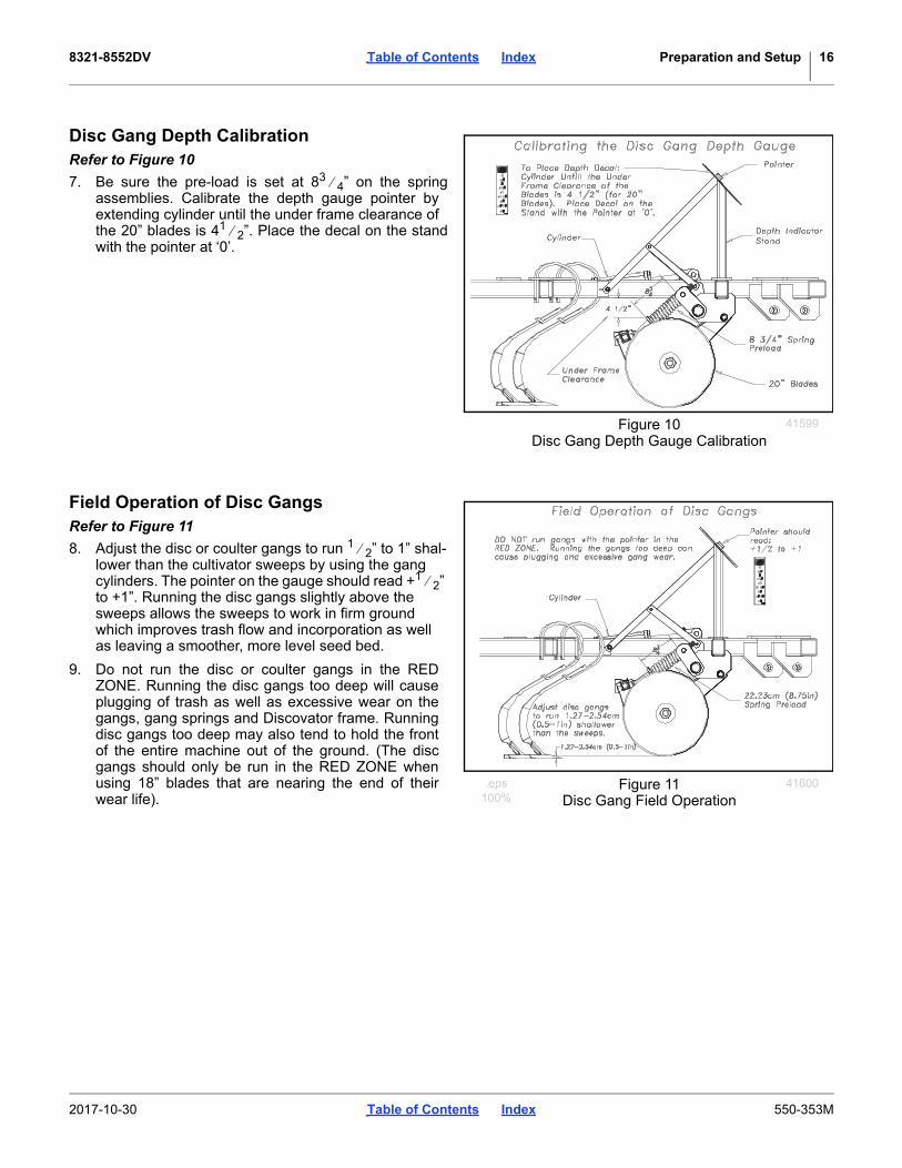
7. Be sure the pre-load is set at 83 4” on the springassemblies. Calibrate the depth gauge pointer byextending cylinder until the under frame clearance ofthe 20” blades is 41 2”. Place the decal on the standwith the pointer at ‘0’.
Field Operation of Disc GangsRefer to Figure 11
8. Adjust the disc or coulter gangs to run 1 2” to 1” shal-lower than the cultivator sweeps by using the gang cylinders. The pointer on the gauge should read +1 2” to +1”. Running the disc gangs slightly above the sweeps allows the sweeps to work in firm ground which improves trash flow and incorporation as well as leaving a smoother, more level seed bed.
9. Do not run the disc or coulter gangs in the REDZONE. Running the disc gangs too deep will causeplugging of trash as well as excessive wear on thegangs, gang springs and Discovator frame. Runningdisc gangs too deep may also tend to hold the frontof the entire machine out of the ground. (The discgangs should only be run in the RED ZONE whenusing 18” blades that are nearing the end of theirwear life).
Figure 10Disc Gang Depth Gauge Calibration
41599
.eps100%
Figure 11Disc Gang Field Operation
41600
2017-10-30 Table of Contents Index 550-353M

8321-8552DV Table of Contents Index Preparation and Setup 17
Refer to Figure 12
10. You are ready to operate the machine in the field atthis point. You should have someone observe themachine during operation for levelness, front to rearand side to side. When you lower the machine to thedesired working depth, set the depth stop at thefront of machine to ensure the unit will operate at aconsistent depth every pass. After setting the stop, ifa change of depth is desired, 1 full turn of the handle
either in or out will change the depthapproximately 1 4” up or down respectively.
11. Make any fine tuning adjustments on the leveling ofthe machine.
1
2
.eps100%
Figure 12Depth Stop Adjustment
42339
1
2
2017-10-30 Table of Contents Index 550-353M
8321-8552DV Table of Contents Index Operating Instructions 18
Operating Instructions
This section covers general operating procedures.Experience, machine familiarity, and the followinginformation will lead to efficient operation and goodworking habits. Always operate farm machinery withsafety in mind.
Pre-Start ChecklistPerform the following steps before transporting theDiscovator to the field.
Carefully read “Important Safety Information” on page 1.
Lubricate Discovator as indicated under “Lubrication” on page 21.
Check all tires for proper inflation.
Check all bolts, pins, and fasteners. Torque as shown in “Torque Values Chart” on page 28.
Check Discovator for worn or damaged parts. Repair or replace parts before going to the field.
Check hydraulic hoses, fittings, and cylinders for leaks. Repair or replace before going to the field.
TransportingSee “Hitching Tractor to Discovator” on page 13before transporting the Discovator.
Check Tractor Capacity and Configuration
• Know the weight of your Discovator (see table onspecification page).
• Consult your tractor manual for 3-point limitations.
• Add weights to tractor as required.
• When determining the weight of your Discovator, besure to include the weight of any options.
Transport Checklist Plan the route. Avoid steep hills. Keep Clearances in
mind.
Make all electrical and hydraulic connections. See “Hitching Tractor to Discovator” on page 13.
Raise Discovator.
Be sure all transport locks are installed.
Always have lights on for highway operation.
Comply with all federal, state and local safety laws when traveling on public roads.
Travel with caution. Allow safe clearance.Remember that the Discovator is wider than the tractor.
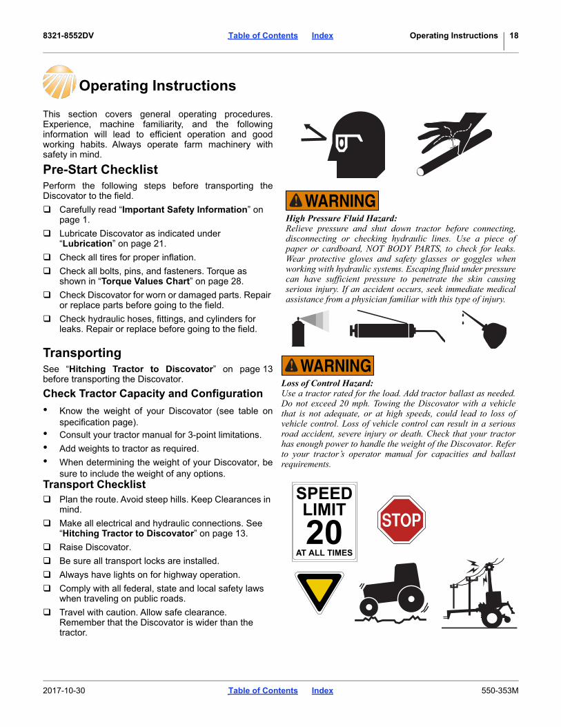
High Pressure Fluid Hazard:Relieve pressure and shut down tractor before connecting,disconnecting or checking hydraulic lines. Use a piece ofpaper or cardboard, NOT BODY PARTS, to check for leaks.Wear protective gloves and safety glasses or goggles whenworking with hydraulic systems. Escaping fluid under pressurecan have sufficient pressure to penetrate the skin causingserious injury. If an accident occurs, seek immediate medicalassistance from a physician familiar with this type of injury.
Loss of Control Hazard:Use a tractor rated for the load. Add tractor ballast as needed.Do not exceed 20 mph. Towing the Discovator with a vehiclethat is not adequate, or at high speeds, could lead to loss ofvehicle control. Loss of vehicle control can result in a seriousroad accident, severe injury or death. Check that your tractorhas enough power to handle the weight of the Discovator. Referto your tractor’s operator manual for capacities and ballastrequirements.
2017-10-30 Table of Contents Index 550-353M

8321-8552DV Table of Contents Index Operating Instructions 19
General Operation and In-Field Adjustments1. Remove the transport pins and unfold machine.
Make sure the fold cylinders are fully extended toallow the wings to fully flex in the field.
2. If possible have someone observe the machineduring first time operation for levelness, front to rearand wings to center frame. Adjust each as needed.For front to rear, either extend or shorten the lengthof the turnbuckle on the self-leveler. Never run themachine with the back lower (deeper) than the front.To adjust the machine from side to side, use theeyebolt on each wing, See “First Time FieldAdjustments” on page 14. The gauge wheels (ifequipped) should be set in field position to be 1 2” to
11 2” off the ground.
3. The ideal working speed for the Discovator is 51 2 to
61 2 mph. Working too slow may cause plugging,poor incorporation or mixing of crop residue andreduced weed kill. Running too fast may causestreaks in chemical incorporation and ridging.
4. The Discovator is designed as a secondary tillagetool and is designed to leave a finished seedbedfollowing some form of fall or spring tillage. For bestresults, if at all possible, run the machine at a slightangle of the rows. This will improve trash flow andhelp spread the residue more evenly throughout thefield.
5. When you have the machine set to the desiredworking depth, set the depth stop slide on the depthcontrol bar. This is located at the front of the machineon the brace bar. This will maintain a constant deptheach time after raising and lowering the machine.
6. If after setting the depth stop, the detent on thetractor kicks out before the stop contacts the buttonon the depth stop, slow the hydraulic flow speeddown. If the problem persists, contact the factoryservice representative for the possible adjustments.Do not try the rebound valve without first contactingthe factory service rep.
7. Adjust the drag to leave the desired results whilemaintaining the trash flow through the drag.
Scraper SettingsThe scrapers are set at the factory but should bechecked periodically and may need re-adjusted asfollows:
• Disc scrapers will need the bolts (rigid scraper) or u-bolts (spring scraper) loosened up and slid into bladeuntil they just touch the blade, and torqued to specs.
• Coulter scrapers u-bolts will need loosened andscrapers centered between coulter blades, andtorqued to specs.
Rear Attachment SettingsSpike Drag SettingsRefer to Figure 13
8. On the spike drag, start with 5 links hanging from thechain in drag arm bottom slot. (This is the startingpoint for worst conditions). The cleaner the ground,the shorter the pull chain may be pulled up. On thespike drag, one of the links in the first row of anglesis turned over. This allows the trash to start flowingthrough the drag easier by changing the angle of thefirst row of teeth. Always make sure that the drag isnever pulling off of the hang chains. If so, shortenpull chains.
Figure 13Spike Drag Settings
41235
2017-10-30 Table of Contents Index 550-353M
8321-8552DV Table of Contents Index Operating Instructions 20
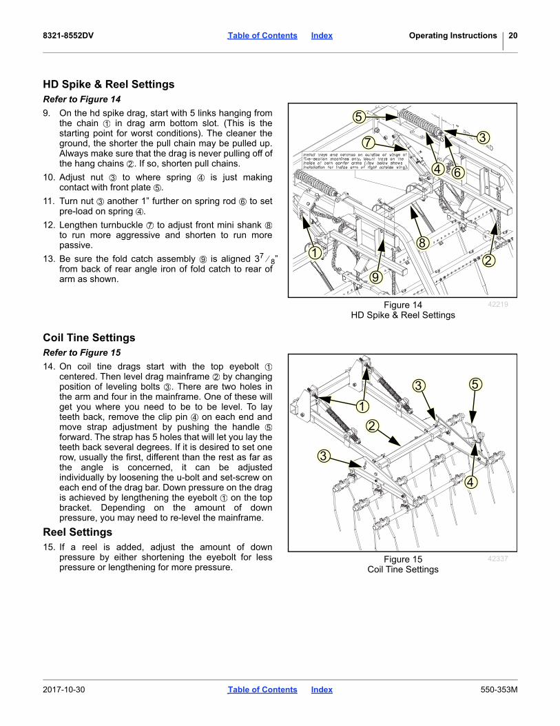
HD Spike & Reel SettingsRefer to Figure 14
9. On the hd spike drag, start with 5 links hanging fromthe chain in drag arm bottom slot. (This is thestarting point for worst conditions). The cleaner theground, the shorter the pull chain may be pulled up.Always make sure that the drag is never pulling off ofthe hang chains . If so, shorten pull chains.
10. Adjust nut to where spring is just makingcontact with front plate .
11. Turn nut another 1” further on spring rod to setpre-load on spring .
12. Lengthen turnbuckle to adjust front mini shank to run more aggressive and shorten to run morepassive.
13. Be sure the fold catch assembly is aligned 37 8”from back of rear angle iron of fold catch to rear ofarm as shown.
Coil Tine SettingsRefer to Figure 15
14. On coil tine drags start with the top eyebolt centered. Then level drag mainframe by changingposition of leveling bolts . There are two holes inthe arm and four in the mainframe. One of these willget you where you need to be to be level. To layteeth back, remove the clip pin on each end andmove strap adjustment by pushing the handle forward. The strap has 5 holes that will let you lay theteeth back several degrees. If it is desired to set onerow, usually the first, different than the rest as far asthe angle is concerned, it can be adjustedindividually by loosening the u-bolt and set-screw oneach end of the drag bar. Down pressure on the dragis achieved by lengthening the eyebolt on the topbracket. Depending on the amount of downpressure, you may need to re-level the mainframe.
Reel Settings15. If a reel is added, adjust the amount of down
pressure by either shortening the eyebolt for lesspressure or lengthening for more pressure.
1
3
9
7
2
5
4 6
8
Figure 14HD Spike & Reel Settings
42219
1
2
3 45
3 64
7 8
9
1
2
3
3
4
5
Figure 15Coil Tine Settings
42337
12
3
45
1
2017-10-30 Table of Contents Index 550-353M

8321-8552DV Table of Contents Index Maintenance and Lubrication 21
Maintenance and Lubrication
Maintenance1. Always use the transport lock when working on or
doing maintenance to the Discovator. If folded, besure your wing stop pins are in place. Read andunderstand all safety decals on your equipment.
2. During the first season of operation, and periodicallyafter that, check your bolts for tightness. Checkshank pivot bolts for tightness. Check shank pivotbolts on the spring-loaded shank, these must remaintight to prevent excessive wear on the shankassembly.
3. Replace or rotate worn parts as needed -- hingebolts, clevis pins, bearings, sweeps, shanks, etc.Boron disc blades cannot be rolled to be sharpened,they must be ground. Cracks and breakage willoccur if rolled.
4. Check and tighten or replace any hydraulic leaks.Check hoses for any leaks. It is important that thereare no leaks on the equipment.
5. Grease wheel bearings and walking beamssparingly. Over greasing may cause damage toseals and reduce the life of the bearing. Greasehinge points periodically.
6. Check drag bolts for loosness or excessive wear.Replace broken or bent teeth. Your drag is animportant part of the tillage operation.
7. If machine is stored outdoors over the wintermonths, it is a good idea to fold the machine then setit down on the ground so all the cylinders areretracted to protect the cylinder rods. This will extendthe life of the cylinder seals and reduce internal andexternal leaks.
By following and maintaining a routine service andlubrication program, your tillage equipment will give youmany years of service.
For the most current manual information, visit GreatPlains website listed below. For more information onoperating, adjusting or maintaining your GreatPlains Discovator, assistance is available. Pleasecontact:
Great Plains Service Department1525 E. North St.
PO Box 5060Salina, KS 67402-5060
Or go to www.greatplainsag.com and follow the contact information at the bottom of your screen for our service
department.
Lubrication
Wheel Bearing Hub
1 zerk on each hub;4 total
Units built after 05/2017 may not have grease zerkson the hubs.
Type of Lubrication: GreaseQuantity: Sparingly, Do Not Over Grease, may causedamage seal.
Repack wheel bearings annually or every 2500 acres.
50
50Multipurpose spray lube
Multipurpose grease lube
Multipurpose oil lube
Intervals (service hours) at which lubrication is required
41622
2017-10-30 Table of Contents Index 550-353M

8321-8552DV Table of Contents Index Maintenance and Lubrication 22
Inside Wing Hinge Points
On all inside wing hinge points
Type of Lubrication: GreaseQuantity: Until grease emerges
Outside Wing Hinge Points
On all outside hinge points
Type of Lubrication: GreaseQuantity: Until grease emerges
Walking Beam Pivot Bearings
One on each walking beam
Type of Lubrication: GreaseQuantity: Sparingly and check for endplay
If there is a lot of end play take apart, check bearings andre-pack
10
10
42335
42336
100
41641
.eps100%
2017-10-30 Table of Contents Index 550-353M

8321-8552DV Table of Contents Index Troubleshooting 23
Troubleshooting
Discovator Trouble Shooting ChartsGeneral Performance
Problem Cause Solution
Rear Shanks Leaving Groove
Rear of machine running too deep.
Coulter/disc gangs too deep.Drag set incorrectly.Operating machine too fast.
Level machine from front to rear with turnbuckle, See “Pre-Leveling of Machine” on page 14Raise disc gangs.Reset drag, See “Rear Attachment Settings” on page 19.Slow down (6-7 m/h)/(9-11 km/h).
Leaving Ridges On The Outside
Wings not level.
Lift cylinders out of phase.Leaking wing lift cylinder.Drag set Incorrectly.
Operating machine too fast.
Adjust eyebolt at rear of wing cylinders to level wings. See “Side to Side Leveling” on page 15.Rephase lift cylinders.Repair or replace leaky cylinder, See pages 34-37 of “Parts Manual”.Reset drag, See “Rear Attachment Settings” on page 19.Slow down (6-7 m/h)/(9-11 km/h)
Wings Not Penetrating
Wings not level.
Coulter/disc gangs too deep.Wing gangs deeper than center gangs.Fold cylinder nor fully extended.
Adjust eyebolt at rear of wing cylinders to level wings. See “Side to Side Leveling” on page 15.Raise disc gangs.Rephase gang circuit.Fully extend cylinders.
One Wing Running Deeper Than The Other
Wings not level.
Leaking wing lift cylinder.
Wing cylinder in wrong sequence.Improper tire pressure.
Adjust eyebolt at rear of wing cylinders to level wings. See “Side to Side Leveling” on page 15.Repair or replace leaky cylinder, See pages 34-37 of “Parts Manual”.Repair or replace leaky cylinder, See pages 26-27 of “Parts Manual”.Set air pressure, See “Tire Inflation and Warranty” on page 26.
Both Wings Running Too Deep
Wings not level.Improper tire pressure.
Adjust eyebolt at rear of wing cylinders to level wings. See “Side to Side Leveling” on page 15.Set air pressure, See “Tire Inflation and Warranty” on page 26.
Whole Machine Runs Deeper
Leaking depth stop cartridge.Leaking master lift cylinder.
Replace cartridge.Repair or replace leaky cylinder, See pages 26-27 of “Parts Manual”.
Center & One Wing Run Deeper
Leaking master lift cylinder. Repair or replace leaky cylinder, See pages 26-27 of “Parts Manual”.
Machine Plugging
Coulter/disc gangs running deeper than sweeps.Machine not level front to back.
Too much residue in the rows.Disc gangs not cutting residue.Improperly spaced shanks.Running too low.Ground too wet.
Raise coulter/disc gangs.
Level machine front to rear with turnbuckle, See “Front to Rear Leveling” on page 14.Run at a slight angle to the rows.Check for sharpness.Check shank layout for proper shank placement.Speed up (6-7 m/h)/(9-11 km/h).Allow ground to dry some.
Machine Bouncing Operating speed too fast. Slow down (6-7 m/h)/(9-11 km/h).
Uneven Working Depth
Lift cylinders out of phase.Timed detent not set correctly.Timed detent not allowing depth stop to engage.
Rephase (See Operators Manual).Set flow for 0.5 after machine is raised.Adjust detent timer to allow for depth stop to engage.
2017-10-30 Table of Contents Index 550-353M
8321-8552DV Table of Contents Index Troubleshooting 24
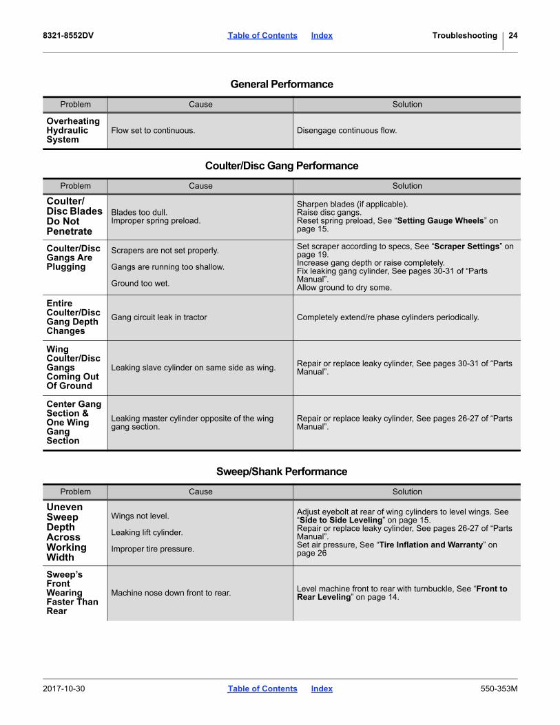
Overheating Hydraulic System
Flow set to continuous. Disengage continuous flow.
Coulter/Disc Gang Performance
Problem Cause Solution
Coulter/Disc Blades Do Not Penetrate
Blades too dull.Improper spring preload.
Sharpen blades (if applicable).Raise disc gangs.Reset spring preload, See “Setting Gauge Wheels” on page 15.
Coulter/Disc Gangs Are Plugging
Scrapers are not set properly.
Gangs are running too shallow.
Ground too wet.
Set scraper according to specs, See “Scraper Settings” on page 19.Increase gang depth or raise completely.Fix leaking gang cylinder, See pages 30-31 of “Parts Manual”.Allow ground to dry some.
Entire Coulter/Disc Gang Depth Changes
Gang circuit leak in tractor Completely extend/re phase cylinders periodically.
Wing Coulter/Disc Gangs Coming Out Of Ground
Leaking slave cylinder on same side as wing. Repair or replace leaky cylinder, See pages 30-31 of “Parts Manual”.
Center Gang Section & One Wing Gang Section
Leaking master cylinder opposite of the wing gang section.
Repair or replace leaky cylinder, See pages 26-27 of “Parts Manual”.
Sweep/Shank Performance
Problem Cause Solution
Uneven Sweep Depth Across Working Width
Wings not level.
Leaking lift cylinder.
Improper tire pressure.
Adjust eyebolt at rear of wing cylinders to level wings. See “Side to Side Leveling” on page 15.Repair or replace leaky cylinder, See pages 26-27 of “Parts Manual”.Set air pressure, See “Tire Inflation and Warranty” on page 26
Sweep’s Front Wearing Faster Than Rear
Machine nose down front to rear. Level machine front to rear with turnbuckle, See “Front to Rear Leveling” on page 14.
General Performance
Problem Cause Solution
2017-10-30 Table of Contents Index 550-353M

8321-8552DV Table of Contents Index Troubleshooting 25
Sweep’s Rear Wearing Faster Than Front
Machine nose up front to rear. Level machine front to rear with turnbuckle, See “Front to Rear Leveling” on page 14.
Magnum Shank Excessive Wear In Pivot Bolt
Loose pivot bolt. Tighten pivot bolt, See pages 40-41 of “Parts Manual”.
Twisted K-Flex Turning while machine in the ground. Raise the machine out of the ground when turning.
Opening K-flex Shank
Turning while in the ground.Backing up while in the ground.
Raise the machine out of the ground.Raise the machine out of the ground.
Bottom C-shank Bending
Running too deep/fast.Improper shank.
Reduce working depth/speed.Switch to Magnum Shank
Transport
Problem Cause Solution
Wings Fail to Unfold
Hydraulic hose disconnected.Failed hydraulic hose tip.Transport locks engaged.
Connect hydraulic hose.Replace tip.Disengage transport locks.
Wings Fail To Fold
Hydraulic hose disconnected.Failed hydraulic hose tip.Low hydraulic pressure.
Connect hydraulic hose.Replace tip.Increase pressure to be>1500psi (10.3x10^6 Pa).
Folds/Unfolds Too Slow
Failed hydraulic hose tip. Replace tip.
Folds/Unfolds Too Fast
Cylinder orifice removed. Replace orifice in cylinder ports.
Lift Circuit immobilized Rebound valve locked. See dealer.
Lift Will Not Go Down
Transport locks engaged.Depth stop engaging.Failed poppet valve in depth stop.Depth stop failing due to hose routing.
Disengage transport locks.Readjust depth stop.Replace poppet valve in depth stop.Check routing with hydraulic layout, “Pre-Delivery Manual”.
Machine Bouncing During Transport
Excessive speed. Slow down (18 m/h)/(30 km/h).
Sweep/Shank Performance
Problem Cause Solution
2017-10-30 Table of Contents Index 550-353M

8321-8552DV Table of Contents Index Appendix 26
Appendix
DV Specifications and Capacities
Weight can vary by hundreds of pounds depending on options installed.
Tire Inflation and Warranty
Tire Inflation Chart Tire Warranty Information
Wheel Tire Size Inflation All tires are warranted by the original manufacturer of the tire. Tire warranty information is found in the brochures included with your Operator’s and Parts Manuals or online at the manufacturer’s web sites listed below. For assistance or information, contact your nearest Authorized Farm Tire Retailer.ManufacturerWeb siteFirestone www.firestoneag.comGleason www.gleasonwheel.comTitan www.titan-intl.comGalaxy www.atgtire.comBKT www.bkt-tire.com
Gauge Wheel 6.70L-15” 4-ply 32psi
(221 kPa)
Gauge Wheel 7.50x10” 10-ply 80 psi
(552 kPa)
Transport/Wings 9.5L-15” 8-Ply 44psi
(303 kPa)
Transport/Center 11L x 15SL 12-Ply 52 psi
(359 kPa)
Transport/Center 11L x 15” Load F 90psi
(621 kPa)
Model No. 8321DV 8324DV 8326DV 8328DV 8333DVSweep Width 20' 7" (6.26 m) 24' 1" (7.35 m) 26' 4" (8.04 m) 28' 9" (8.76 m) 33' 5" (10.2 m)Coulter/Disc Width 20' (6.09 m) 23' 9" (7.28 m) 25' 3" (7.70 m) 28' (8.53 m) 32' (9.75 m)Number of Sweeps 35 41 45 49 57Number of Coulter/Disc 30 36 38 42 48Center Section 9' 9" (2.97 m) 9' 9" (2.97 m) 9' 9" (2.97 m) 9' 9" (2.97 m) 12' (3.66)Wing 5' 6" (1.68 m) 7' 6" (2.29 m) 8' 6" (2.59 m) 9' 6" (2.90 m) 10' 6" (3.2 m)Transport Width 14' (4.27 m) 14' (4.27 m) 14' (4.27 m) 14' (4.27 m) 16' 1" (4.90 m)Transport Height 9' 3" (2.82 m) 10' 9" (3.28 m) 12' (3.66 m) 13' 3" (4.04 m) 14' 3" (4.34 m)Weight 8925 lb (4048 kg) 10200 lb (4626 kg) 11050 lb (5012 kg) 11890 lb (5393 kg) 14025 lb (6361 kg)Tire Size Center 9.5 LX15 8 PLY 9.5 LX15 8 PLY 11L-15SL 12 PLY 11L-15SL 12 PLY 11L-15SL 12 PLYTire Size Wing 9.5 LX15 8 PLY 9.5 LX15 8 PLY 9.5 LX15 8 PLY 9.5 LX15 8 PLY 9.5 LX15 8 PLYHorsepower 125-175 160-210 200-250 225-275 250-300Kilowatt 93-130 119-156 149-186 167-205 186-223
Model No. 8537DV 8544DV 8548DV 8552DVSweep Width 36' 11" (11.25 m) 43' 11" (13.4 m) 47' 5" (14.47 m) 52' 1" (15.86 m)Coulter/Disc Width 36' (10.97 m) 42' 9" (13.03 m) 46' 6" (14.17 m) 50' 9" (15.47 m)Number of Sweeps 63 75 81 89Number of Coulter/Disc 54 64 70 76Center Section 9' 9" (2.97 m) 9' 9" (2.97 m) 12' (3.66) 12' (3.66)1st Wing 8' 6" (2.59 m) 9' 6" (2.90 m) 10' 9" (3.28 m) 10' 9" (3.28 m)2nd Wing 5' (1.52 m) 7' 3" (2.21 m) 7' (2.13 m) 9' 3" (2.82 m)Transport Width 15' (4.57 m) 15' (4.57 m) 18' 3" (5.56 m) 18' 3" (5.56 m)Transport Height 12' 6" (3.81 m) 13' 3" (4.04 m) 14' 9" (4.50 m) 14' 9" (4.50 m)Weight 15392 lb (6981 kg) 18320 lb (8309 kg) 19968 lb (9057 kg) 21632 lb (9812 kg)Tire Size Center 11LX15 LOAD F 12.5LX15 LOAD F 12.5LX16.5/G 12.5LX16.5/GTire Size Wings 9.5 LX15 8 PLY 9.5 LX15 8 PLY 9.5 LX15 8 PLY 9.5 LX15 8 PLYHorsepower 280-340 320-380 340-400 375+Kilowatt 208-253 238-283 340-298 279+
2017-10-30 Table of Contents Index 550-353M
8321-8552DV Table of Contents Index Appendix 27
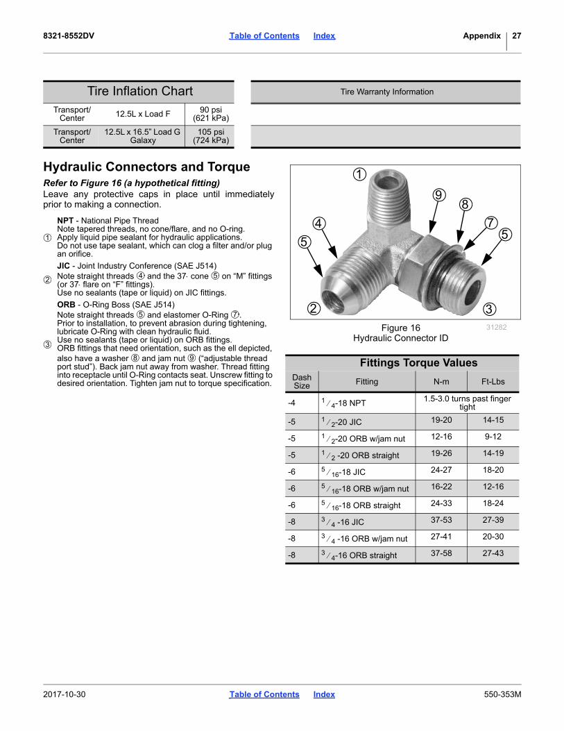
Hydraulic Connectors and TorqueRefer to Figure 16 (a hypothetical fitting)Leave any protective caps in place until immediatelyprior to making a connection.
Transport/Center 12.5L x Load F 90 psi
(621 kPa)
Transport/Center
12.5L x 16.5” Load G Galaxy
105 psi(724 kPa)
NPT - National Pipe ThreadNote tapered threads, no cone/flare, and no O-ring.Apply liquid pipe sealant for hydraulic applications.Do not use tape sealant, which can clog a filter and/or plug an orifice.
JIC - Joint Industry Conference (SAE J514)Note straight threads and the 37 cone on “M” fittings (or 37 flare on “F” fittings).Use no sealants (tape or liquid) on JIC fittings.
ORB - O-Ring Boss (SAE J514)Note straight threads and elastomer O-Ring .Prior to installation, to prevent abrasion during tightening, lubricate O-Ring with clean hydraulic fluid.Use no sealants (tape or liquid) on ORB fittings.ORB fittings that need orientation, such as the ell depicted, also have a washer and jam nut (“adjustable thread port stud”). Back jam nut away from washer. Thread fitting into receptacle until O-Ring contacts seat. Unscrew fitting to desired orientation. Tighten jam nut to torque specification.
Tire Inflation Chart Tire Warranty Information
2
5
4
98
75
3
Figure 16Hydraulic Connector ID
31282
Fittings Torque ValuesDash Size Fitting N-m Ft-Lbs
-4 1 4-18 NPT 1.5-3.0 turns past finger tight
-5 1 2-20 JIC 19-20 14-15
-5 1 2-20 ORB w/jam nut 12-16 9-12
-5 1 2 -20 ORB straight 19-26 14-19
-6 5 16-18 JIC 24-27 18-20
-6 5 16-18 ORB w/jam nut 16-22 12-16
-6 5 16-18 ORB straight 24-33 18-24
-8 3 4 -16 JIC 37-53 27-39
-8 3 4 -16 ORB w/jam nut 27-41 20-30
-8 3 4-16 ORB straight 37-58 27-43
1
1
24 5
3
5 7
8 9
2017-10-30 Table of Contents Index 550-353M

8321-8552DV Table of Contents Index Appendix 28
Torque Values Chart
Disc or Coulter Gang Bolt Torque 11 2”-6 650-750 Foot-pounds (175 lbs on 4’ cheater).
Torque Values Chart
Wheel Bolt Torque Values 1 2”-20 (75-85ft-lbs)
Wheel Bolt Torque Values 9 16”-18 (80-90ft-lbs)
Wheel Bolt Torque Values 5 8”-18 (85-100ft-lbs)
94 6
25199m
BoltSize
Bolt Head IdentificationBoltSize
Bolt Head Identification
Grade 2 Grade 5 Grade 8 Class 5.8 Class 8.8 Class 10.9in-tpia N-mb N-m N-m mm x pitchc N-m N-m N-m1⁄4-20 7.4 11 16 M 5 X 0.81⁄4-28 8.5 13 18 M 6 X 1 7 11 155⁄16-18 15 24 33 M 8 X 1.25 17 26 365⁄16-24 17 26 37 M 8 X 1 18 28 393⁄8-16 27 42 59 M10 X 1.5 33 52 723⁄8-24 31 47 67 M10 X 0.75 39 61 857⁄16-14 43 67 95 M12 X 1.75 58 91 1257⁄16-20 49 75 105 M12 X 1.5 60 95 1301⁄2-13 66 105 145 M12 X 1 90 105 1451⁄2-20 75 115 165 M14 X 2 92 145 2009⁄16-12 95 150 210 M14 X 1.5 99 155 2159⁄16-18 105 165 235 M16 X 2 145 225 3155⁄8-11 130 205 285 M16 X 1.5 155 240 3355⁄8-18 150 230 325 M18 X 2.5 195 310 4053⁄4-10 235 360 510 M18 X 1.5 220 350 4853⁄4-16 260 405 570 M20 X 2.5 280 440 6107⁄8-9 225 585 820 M20 X 1.5 310 650 900
7⁄8-14 250 640 905 M24 X 3 480 760 1050
1-8 340 875 1230 M24 X 2 525 830 1150
1-12 370 955 1350 M30 X 3.5 960 1510 2100
11⁄8-7 480 1080 1750 M30 X 2 1060 1680 2320
11⁄8-12 540 1210 1960 M36 X 3.5 1730 2650 3660
11⁄4-7 680 1520 2460 M36 X 2 1880 2960 4100
11⁄4-12 750 1680 2730
13⁄8-6 890 1990 3230 a. in-tpi = nominal thread diameter in inches-threads per inch
13⁄8-12 1010 2270 3680 b. N· m = newton-meters
11⁄2-6 1180 2640 4290
11⁄2-12 1330 2970 4820
c. mm x pitch = nominal thread diameter in mm x thread pitch
Torque tolerance + 0%, -15% of torquing values. Unless otherwise specified use torque values listed above.
5.8 8.8 10.9
25199
ft-lbd ft-lb ft-lb ft-lb ft-lb ft-lb5.6 8 12
6 10 14 5 8 11
11 17 25 12 19 27
13 19 27 13 21 29
20 31 44 24 39 53
22 35 49 29 45 62
32 49 70 42 67 93
36 55 78 44 70 97
49 76 105 66 77 105
55 85 120 68 105 150
70 110 155 73 115 160
79 120 170 105 165 230
97 150 210 115 180 245
110 170 240 145 230 300
170 265 375 165 260 355
190 295 420 205 325 450
165 430 605 230 480 665
185 475 670 355 560 780
250 645 910 390 610 845
275 705 995 705 1120 1550
355 795 1290 785 1240 1710
395 890 1440 1270 1950 2700
500 1120 1820 1380 2190 3220
555 1240 2010
655 1470 2380
745 1670 2710
870 1950 3160d. ft-lb = foot pounds
980 2190 3560
3 5 7
2017-10-30 Table of Contents Index 550-353M
8321-8552DV Table of Contents Index Appendix 29
2017-10-30 Table of Contents Index 550-353M

8321-8552DV Table of Contents Index Appendix 30
2017-10-30 Table of Contents Index 550-353M

8321-8552DV Cover Table of Contents Index 31
Index
Aaddress, Great Plains .................. 11,21amber reflectors ...................................5
Bbearings ..............................................21bolts ....................................................21
CCaution
Read Operator’s Manual ...............6CAUTION, defined ...............................1chain ...................................................13checklists
pre-setup .....................................12pre-start .......................................18transport ......................................18
chemicals .............................................2children .................................................2clothing .................................................2coil tine drags .....................................20color code, hose .................................14contact Great Plains .................... 11,21Coulter scrapers .................................19covered models ..................................10customer service ................................11
DDanger
Crushing Hazard ...................... 7,9DANGER, defined ................................1decal replacement ................................5decals
cautionread manual ...........................6tire pressure and torque .........9
dangercrushing .................................7electrocution ...........................7
noticetransport lock .........................8
speed30km per hr ............................9
warninghand crushing ........................8high pressure fluid ..................8overhead wing ........................7speed .....................................9wings could fall .......................9
decal, safety .........................................5definitions ...........................................10directions ............................................10Disc Gang Depth Gauge Calibration 15,16Disc Gang Field Operation .......... 16,17Disc or Coulter Gang Bearing ............22
Disc scrapers ..................................... 19drag bolts ........................................... 21
Eemail, Great Plains .......................11,21
Ffire ........................................................ 1
Hhd spike & reel drag ........................... 20headphones ......................................... 2hearing ................................................. 2high pressure fluids .............................. 2hills ..................................................... 13Hinge Points ....................................... 22hinge points
inside wing .................................. 22outside wing ................................ 22
Hitch Turnbuckle Adjustment ............. 14hitching............................................... 13hose handles...................................... 14hydraulic connectors .......................... 27hydraulic safety .................................... 2
Iinflation............................................... 26
JJIC...................................................... 27Joint Industry Conference .................. 27J514 ................................................... 27
Lleaks...............................................2,21left-hand, defined ............................... 10lights..................................................... 2lubrication ........................................... 21
MMaintenance ...................................... 21maintenance safety .............................. 4medical assistance..................2,14,18model number .................................... 11
NNational Pipe Thread ......................... 27Note, defined...................................... 10Notice, defined ................................... 10NPT .................................................... 27
Oorange reflector .................................... 6ORB ................................................... 27orientation rose .................................. 10O-Ring Boss....................................... 27owner assistance ............................... 11
Pparts ................................................... 21phone number, GP............................. 12
Pre-leveling of machine ......................14protective equipment ............................2
Rred reflectors.........................................6reel ......................................................20reflectors
amber ............................................5orange ...........................................6red .................................................6SMV...............................................5
reflectors, safety ...................................5repair parts .........................................11riders.....................................................2right-hand, defined..............................10rose, oriention .....................................10
SSAE J514............................................27safety chain ........................................13safety decal ..........................................5safety information .................................1safety symbol........................................1serial number ......................................11setup ...................................................12shutdown ..............................................3slopes .................................................13SMV (Slow Moving Vehicle) .................5Spanish....................................... 6,7,9Specifications and Capacities.............26speed ....................................................7spike drag ...........................................19storage..................................................3storing machine ..................................21support......................................... 11,21symbol, safety.......................................1
Ttables
document family ..........................10fittings torque ...............................27hose color code ...........................14models covered ...........................10torque values ...............................28
tire inflation .........................................26tires .......................................................3transport .............................................18transport lock ......................................21transport speed.....................................3transporting.........................................18troubleshooting
coulter/disc gang .........................24general ........................................23sweep/shank ...............................24transport ......................................25
2017-10-30 Cover Table of Contents 550-353M

8321-8552DV Cover Table of Contents Index 32
UURLs, tires ..........................................26
WWARNING, defined ..............................1warranty ..............................................29
tire ...............................................26welding .................................................4Wheel Bearing Hub ............................21Wing Depth Adjustment ......................15www....................................................26
Numerics13 mph .................................................320 mph .......................................... 3,1822 kph ...................................................332 kph ...................................................3550-353M, manual .............................10550-353P, manual ..............................10550-353Q-ENG, manual .....................10550-353Q, manual ..............................10818-055C, reflector ...............................5818-188C, decal ...................................9838-094C, decal ...................................8838-598C, decal ...................................6838-599C, decal ...................................7838-600C, decal ...................................7838-602C, decal ...................................7838-603C, reflector ...............................6838-611C, decal ...................................8838-612C, decal ...................................9838-613C, decal ...................................8838-614C, reflector ...............................6838-615C, reflector ...............................5838-890C, decal ...................................9
2017-10-30 Cover Table of Contents 550-353M

Table of Contents Index
Table of Contents Index

Great Plains, Mfg.1525 E. North St.P.O. Box 5060Salina, KS 67402