operator & parts manual - degelmandegelman.com/assets/manuals/143390-lr-five-plex.pdf ·...
TRANSCRIPT
OPERATOR & PARTS MANUAL
D E G E L M A N I N D U S T R I E S L T D.B O X 8 3 0 - 2 7 2 I N D U S T R I A L D R I V E ,R E G I N A , S K , C A N A D A , S 4 P 3 B 1FA X 306.543.2140 P H 3 0 6 . 5 4 3 . 4 4 4 71 . 8 0 0 . 6 6 7 . 3 5 4 5 D E G E L M A N . C O M
LANDROLLER 8000 FIVE-PLEX LR8064 & LR8080
Serial Numbers 7220 and above
143390 v1.0


1
2
2
2
4
4
4
2
2
3
5
7
56
5
A
B
Connect Hydraulics
Backing Into Field Position
ROLLER LIFT CIRCUIT....................Wheel Cylinders
FRONT HITCH CIRCUIT..............Front Hitch Cylinder
SPREADER ARM CIRCUIT....Spreader Arm Cylinders3
2
1
142645 v1.1
1) Drive landroller onto level ground, straight behind the tractor.
- Ensure there is plenty of room behind and to the sides of the landroller for backing into fi eld position.
2) Remove all fi ve red transport bars. Place the transport bars onto the storage brackets provided and secure with lock-pin.
(4 on wheel cylinders, and 1 on front hitch cylinder).
Note: You may need to activate (extend) the hydraulic cylinders slightly to allow removal of the cylinder transport bars.
3) Slowly back-up while activating the spreader arm hydraulics until the wings are mostly open or approximately 15º-30º degrees from being in line.
4) Fully raise the transport wheels to lower the rollers to the ground.
5) Continue backing up until both Swing-Arms lock into the latches.
6) IMPORTANT: Set the tractor hydraulic remote that activates the hitch pole cylinder into “fl oat” position. This will allow the hitch pole to contour more effectively and prevent strain or possible damage to the machine.
7) The Landroller is now in fi eld ready position.
3
The spreader arms willassist to spread the
wings apart. - Retract this circuit upon completion -
QUICK-START GUIDE*
for LANDROLLER Five Plex* Refer to operators manual for complete safety and operation info.
TO BE ELIGIBLE FOR
YOU MUST REGISTER
WARRANTY
REMEMBER! You must complete ProductRegistration to be eligible for Warranty.
55
6
4
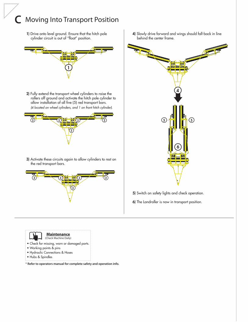
5) Switch on safety lights and check operation.
6) The Landroller is now in transport position.
4) Slowly drive forward and wings should fall-back in line behind the center frame.
1) Drive onto level ground. Ensure that the hitch pole cylinder circuit is out of “fl oat” position.
2) Fully extend the transport wheel cylinders to raise the rollers off ground and activate the hitch pole cylinder to allow installation of all fi ve (5) red transport bars.
(4 located on wheel cylinders, and 1 on front hitch cylinder).
C Moving Into Transport Position
1
2 2
2
22
3) Activate these circuits again to allow cylinders to rest on the red transport bars.
3 3
3
33
* Refer to operators manual for complete safety and operation info.
• Check for missing, worn or damaged parts.• Working points & pins• Hydraulic Connections & Hoses• Hubs & Spindles
Maintenance (Check Machine Daily)
IMPORTANT:
READ MANUAL
D E G E L M A N I N D U S T R I E S L T D.B O X 8 3 0 - 2 7 2 I N D U S T R I A L D R I V E ,R E G I N A , S K , C A N A D A , S 4 P 3 B 1FA X 306.543.2140 P H 3 0 6 . 5 4 3 . 4 4 4 71 . 8 0 0 . 6 6 7 . 3 5 4 5 D E G E L M A N . C O M
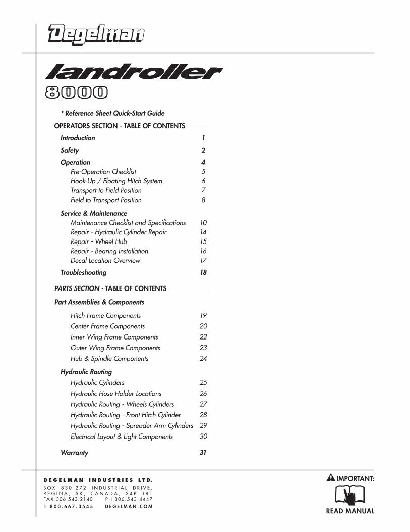
* Reference Sheet Quick-Start Guide
OPERATORS SECTION - TABLE OF CONTENTS
Introduction 1
Safety 2
Operation 4 Pre-Operation Checklist 5 Hook-Up / Floating Hitch System 6 Transport to Field Position 7 Field to Transport Position 8
Service & Maintenance Maintenance Checklist and Specifications 10 Repair - Hydraulic Cylinder Repair 14 Repair - Wheel Hub 15 Repair - Bearing Installation 16 Decal Location Overview 17
Troubleshooting 18
PARTS SECTION - TABLE OF CONTENTS
Part Assemblies & Components
Hitch Frame Components 19 Center Frame Components 20 Inner Wing Frame Components 22 Outer Wing Frame Components 23 Hub & Spindle Components 24
Hydraulic Routing Hydraulic Cylinders 25 Hydraulic Hose Holder Locations 26
Hydraulic Routing - Wheels Cylinders 27 Hydraulic Routing - Front Hitch Cylinder 28 Hydraulic Routing - Spreader Arm Cylinders 29 Electrical Layout & Light Components 30
Warranty 31

-1-143390 - LR 8000 Five-Plex (01-May-2017)
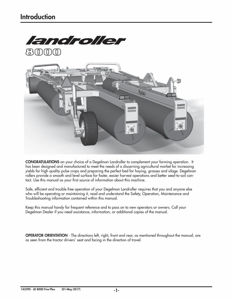
Introduction
OPERATOR ORIENTATION - The directions left, right, front and rear, as mentioned throughout the manual, are as seen from the tractor drivers’ seat and facing in the direction of travel.
CONGRATULATIONS on your choice of a Degelman Landroller to complement your farming operation. It has been designed and manufactured to meet the needs of a discerning agricultural market for increasing yields for high quality pulse crops and preparing the perfect bed for haying, grasses and silage. Degelman rollers provide a smooth and level surface for faster, easier harvest operations and better seed-to-soil con-tact. Use this manual as your first source of information about this machine.
Safe, efficient and trouble free operation of your Degelman Landroller requires that you and anyone else who will be operating or maintaining it, read and understand the Safety, Operation, Maintenance and Troubleshooting information contained within this manual.
Keep this manual handy for frequent reference and to pass on to new operators or owners. Call your Degelman Dealer if you need assistance, information, or additional copies of the manual.
-2-143390 - LR 8000 Five-Plex (01-May-2017)
CAUTION
DANGER
WARNING
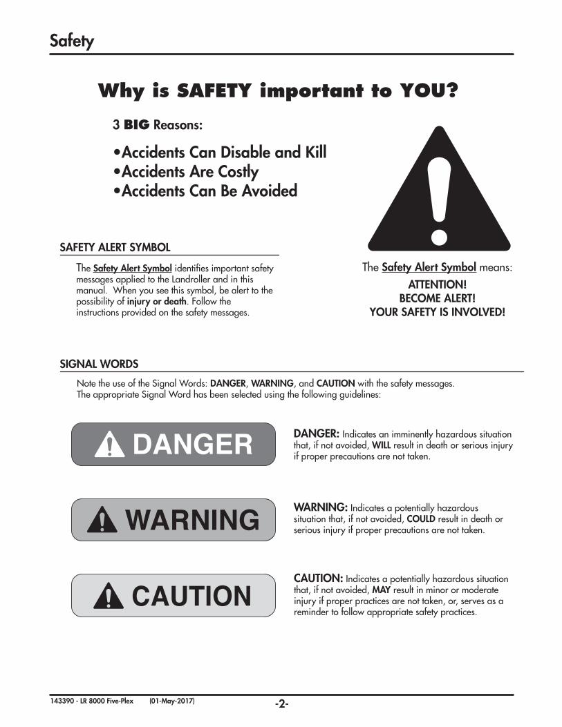
The Safety Alert Symbol identifies important safety messages applied to the Landroller and in this manual. When you see this symbol, be alert to the possibility of injury or death. Follow the instructions provided on the safety messages.
The Safety Alert Symbol means:
ATTENTION! BECOME ALERT!
YOUR SAFETY IS INVOLVED!
DANGER: Indicates an imminently hazardous situation that, if not avoided, WILL result in death or serious injury if proper precautions are not taken.
WARNING: Indicates a potentially hazardous situation that, if not avoided, COULD result in death or serious injury if proper precautions are not taken.
CAUTION: Indicates a potentially hazardous situation that, if not avoided, MAY result in minor or moderate injury if proper practices are not taken, or, serves as a reminder to follow appropriate safety practices.
Why is SAFETY important to YOU?
3 BIG Reasons:
•Accidents Can Disable and Kill •Accidents Are Costly •Accidents Can Be Avoided
Note the use of the Signal Words: DANGER, WARNING, and CAUTION with the safety messages. The appropriate Signal Word has been selected using the following guidelines:
SAFETY ALERT SYMBOL
SIGNAL WORDS
Safety
-3-143390 - LR 8000 Five-Plex (01-May-2017)
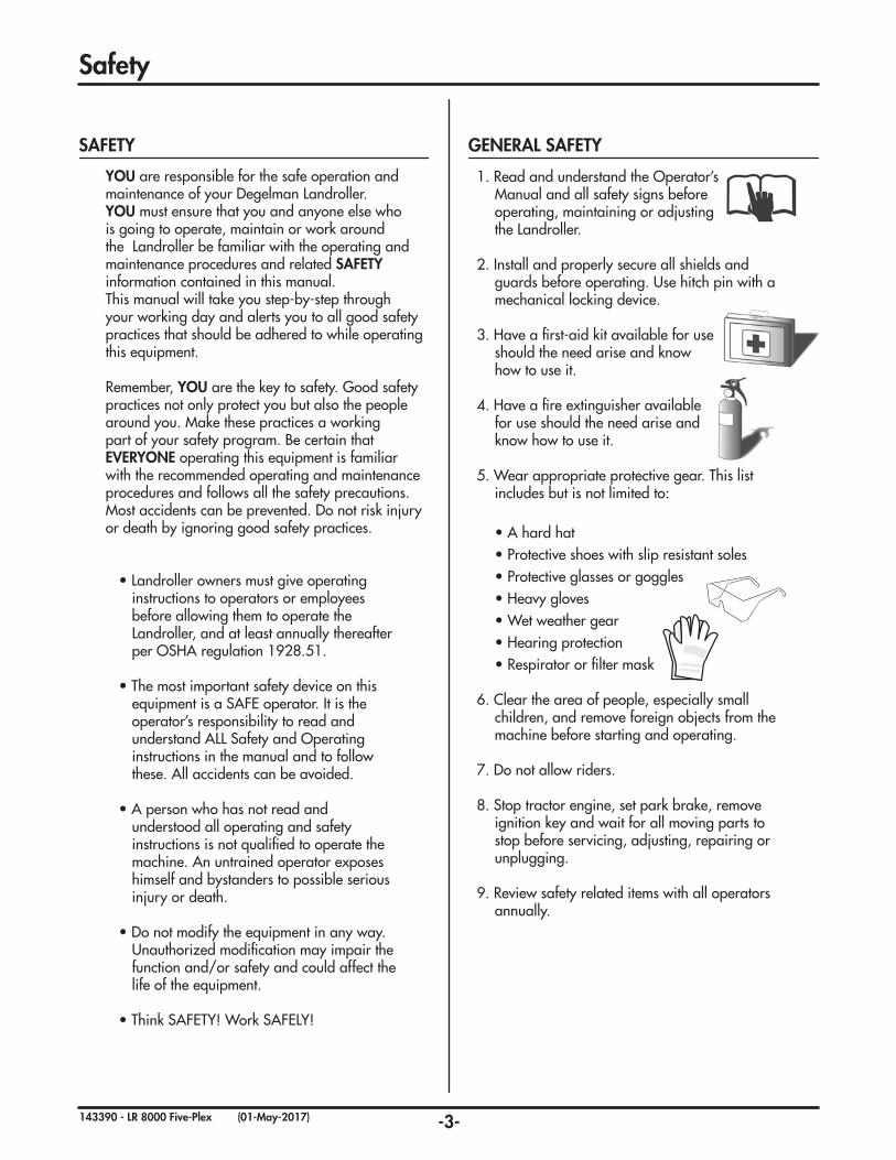
1. Read and understand the Operator’s Manual and all safety signs before operating, maintaining or adjusting the Landroller.
2. Install and properly secure all shields and guards before operating. Use hitch pin with a mechanical locking device.
3. Have a first-aid kit available for use should the need arise and know how to use it.
4. Have a fire extinguisher available for use should the need arise and know how to use it.
5. Wear appropriate protective gear. This list includes but is not limited to:
• A hard hat• Protective shoes with slip resistant soles• Protective glasses or goggles• Heavy gloves• Wet weather gear• Hearing protection• Respirator or filter mask
6. Clear the area of people, especially small children, and remove foreign objects from the machine before starting and operating.
7. Do not allow riders.
8. Stop tractor engine, set park brake, remove ignition key and wait for all moving parts to stop before servicing, adjusting, repairing or unplugging.
9. Review safety related items with all operators annually.
YOU are responsible for the safe operation andmaintenance of your Degelman Landroller.YOU must ensure that you and anyone else who is going to operate, maintain or work around the Landroller be familiar with the operating and maintenance procedures and related SAFETY information contained in this manual.This manual will take you step-by-step through your working day and alerts you to all good safety practices that should be adhered to while operating this equipment.
Remember, YOU are the key to safety. Good safety practices not only protect you but also the people around you. Make these practices a working part of your safety program. Be certain that EVERYONE operating this equipment is familiar with the recommended operating and maintenance procedures and follows all the safety precautions. Most accidents can be prevented. Do not risk injury or death by ignoring good safety practices.
• Landroller owners must give operating instructions to operators or employees before allowing them to operate the Landroller, and at least annually thereafter per OSHA regulation 1928.51.
• The most important safety device on this equipment is a SAFE operator. It is the operator’s responsibility to read and understand ALL Safety and Operating instructions in the manual and to follow these. All accidents can be avoided.
• A person who has not read and understood all operating and safety instructions is not qualified to operate the machine. An untrained operator exposes himself and bystanders to possible serious injury or death.
• Do not modify the equipment in any way. Unauthorized modification may impair the function and/or safety and could affect the life of the equipment.
• Think SAFETY! Work SAFELY!
Safety
SAFETY GENERAL SAFETY
-4-143390 - LR 8000 Five-Plex (01-May-2017)
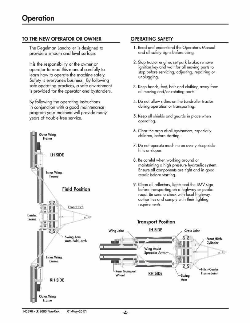
Transport Position
Rear Transport Wheel
Wing Joint
Hitch-Center Frame Joint
Wing AssistSpreader Arms
Swing Arm
Front Hitch Cylinder
Cross Joint
Field Position
Swing Arm Auto-Fold Latch
Front Hitch
Center Frame
Outer Wing Frame
Inner Wing Frame
Inner Wing Frame
Outer Wing Frame
LH SIDE
LH SIDE
RH SIDE
RH SIDE
The Degelman Landroller is designed to provide a smooth and level surface.
It is the responsibility of the owner or operator to read this manual carefully to learn how to operate the machine safely. Safety is everyone’s business. By following safe operating practices, a safe environment is provided for the operator and bystanders.
By following the operating instructions in conjunction with a good maintenance program your machine will provide many years of trouble-free service.
Operation
TO THE NEW OPERATOR OR OWNER
1. Read and understand the Operator’s Manual and all safety signs before using.
2. Stop tractor engine, set park brake, remove ignition key and wait for all moving parts to stop before servicing, adjusting, repairing or unplugging.
3. Keep hands, feet, hair and clothing away from all moving and/or rotating parts.
4. Do not allow riders on the Landroller tractor during operation or transporting.
5. Keep all shields and guards in place when operating.
6. Clear the area of all bystanders, especially children, before starting.
7. Do not operate machine on overly steep side hills or slopes.
8. Be careful when working around or maintaining a high-pressure hydraulic system. Ensure all components are tight and in good repair before starting.
9. Clean all reflectors, lights and the SMV sign before transporting on a highway or public road. Be sure to check with local highway authorities and comply with their lighting requirements.
OPERATING SAFETY
-5-143390 - LR 8000 Five-Plex (01-May-2017)
Although there are no operational restrictions on the Landroller when it is new, there are some checks that should be done when using the machine for the first time, follow this procedure:
IMPORTANT: It is important to follow the Break-In procedures especially those listed in the “Before using” section below to avoid damage:
A. Before using:
1. Read Safety Info. & Operator’s Manual.
2. Complete steps in “Pre-Operation Checklist”.
3. Lubricate all grease points.
(Note: Do NOT grease the spherical bearings on the roller ends even though they may have grease fittings. They come pre-lubricated and sealed from the factory)
4. Check all bolt tightness.
5. Check tires. Inflate to:
Front Tires: 12.5L x 15-12 PLY 90 PSI (620 kPa)
Rear Tires: 385/65R x 22.5 90 PSI (620 kPa)
B. After operating for 2 hours:
1. Check all hardware. Tighten as required.
2. Check all hydraulic system connections. Tighten if any are leaking.
BREAK-IN
Before operating the machine and each time there-after, the following areas should be checked off:
1. Lubricate the machine per the schedule outlined in the “Maintenance Section”.
2. Use only a tractor with adequate power to pull the Landroller under ordinary operating conditions. Minimum: 250 HP (186 KW)
3. Ensure that the machine is properly attached to the tractor using a drawbar pin with provisions for a mechanical retainer. Make sure that a re-tainer such as a Klik pin is installed.
NOTE: It is important to pin the draw bar in the central location only.
4. Before using, inflate tires to:
Front Tires: 12.5L x 15-12 PLY 90 PSI (620 kPa)
Rear Tires: 385/65R x 22.5 90 PSI (620 kPa)
5. Ensure that a safety chain is installed on the hitch.
6. Check oil level in the tractor hydraulic reservoir. Top up as required.
7. Inspect all hydraulic lines, hoses, fittings and couplers for tightness. Tighten if there are leaks. Use a clean cloth to wipe any accumulated dirt from the couplers before connecting to the trac-tor’s hydraulic system.
PRE-OPERATION CHECKLIST
It is important for both personal safety and maintaining good operational condition of the machine that the pre-operational checklist be followed.
Operation
-6-143390 - LR 8000 Five-Plex (01-May-2017)
The Landroller should always be parked on a level, dry area that is free of debris and foreign objects. Follow this procedure to hook-up:
1. Clear the area of bystanders and remove foreign objects from the machine and working area.
2. Make sure there is enough room to back the tractor up to the trailer hitch.
3. Start the tractor and slowly back it up to the hitch point.
4. Stop the tractor engine, place all controls in neutral, set park brake and remove ignition key before dismounting.
5. Use the jack to raise or lower the hitch to align with the drawbar.
6. Install a drawbar pin with provisions for a mechanical retainer such as a KLIK pin.
Install the retainer.
7. Install a safety chain between the tractor and the hitch.
8. Connect the hydraulics. To connect, proceed as follows:
• Use a clean cloth or paper towel to clean the couplers on the ends of the hoses. Also clean the area around the couplers on the tractor. Remove the plastic plugs from the couplers and insert the male ends.
• Be sure to match the pressure and return line to one valve bank.
9. Connect lights (electrical socket plug) to tractor.
10. Raise the hitch jack and rotate it 90º to place in its stowed position.
11. When unhooking from the tractor, reverse the above procedure.
HOOK-UP / UNHOOKING FLOATING HITCH SYSTEM
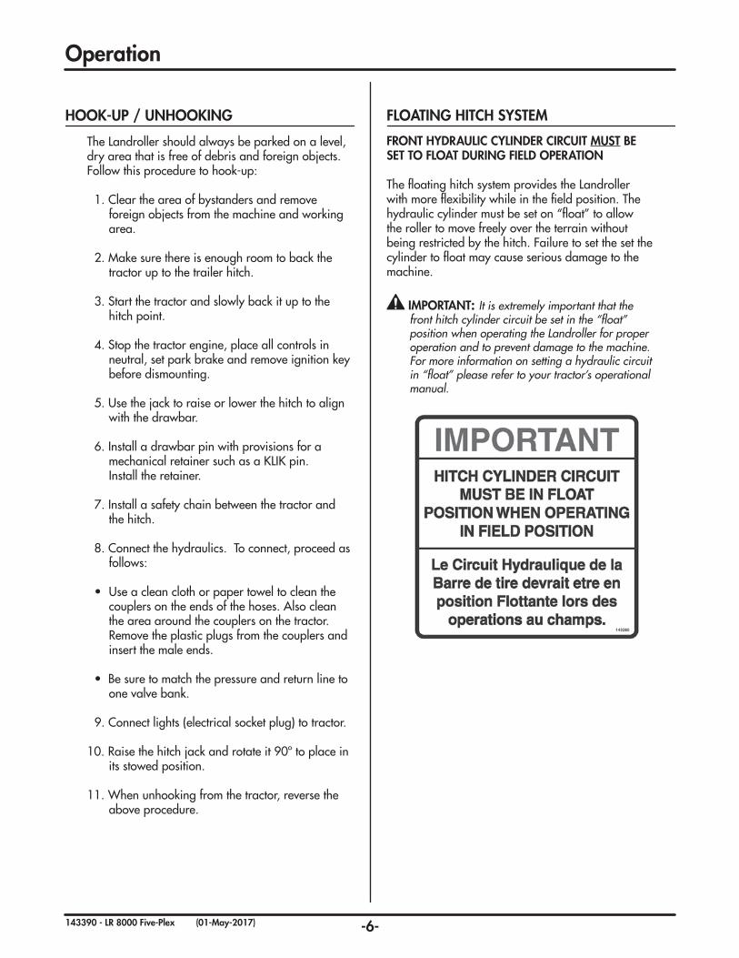
FRONT HYDRAULIC CYLINDER CIRCUIT MUST BE SET TO FLOAT DURING FIELD OPERATION
The floating hitch system provides the Landroller with more flexibility while in the field position. The hydraulic cylinder must be set on “float” to allow the roller to move freely over the terrain without being restricted by the hitch. Failure to set the set the cylinder to float may cause serious damage to the machine.
IMPORTANT: It is extremely important that the front hitch cylinder circuit be set in the “float” position when operating the Landroller for proper operation and to prevent damage to the machine. For more information on setting a hydraulic circuit in “float” please refer to your tractor’s operational manual.
Operation
-7-143390 - LR 8000 Five-Plex (01-May-2017)
1
2
2 2
22
3
4
5
6
7
Operation
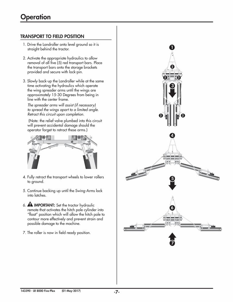
1. Drive the Landroller onto level ground so it is straight behind the tractor.
2. Activate the appropriate hydraulics to allow removal of all five (5) red transport bars. Place the transport bars onto the storage brackets provided and secure with lock-pin.
3. Slowly back-up the Landroller while at the same time activating the hydraulics which operate the wing spreader arms until the wings are approximately 15-30 Degrees from being in line with the center frame.
The spreader arms will assist (if necessary) to spread the wings apart to a limited angle. Retract this circuit upon completion.
(Note: the relief valve plumbed into this circuit will prevent accidental damage should the operator forget to retract these arms.)
4. Fully retract the transport wheels to lower rollers
to ground.
5. Continue backing up until the Swing-Arms lock into latches.
6. IMPORTANT: Set the tractor hydraulic remote that activates the hitch pole cylinder into “float” position which will allow the hitch pole to contour more effectively and prevent strain and possible damage to the machine.
7. The roller is now in field ready position.
TRANSPORT TO FIELD POSITION
-8-143390 - LR 8000 Five-Plex (01-May-2017)
2
6
2
2
1
3
3
3
4
55
2 2
3 3
Operation
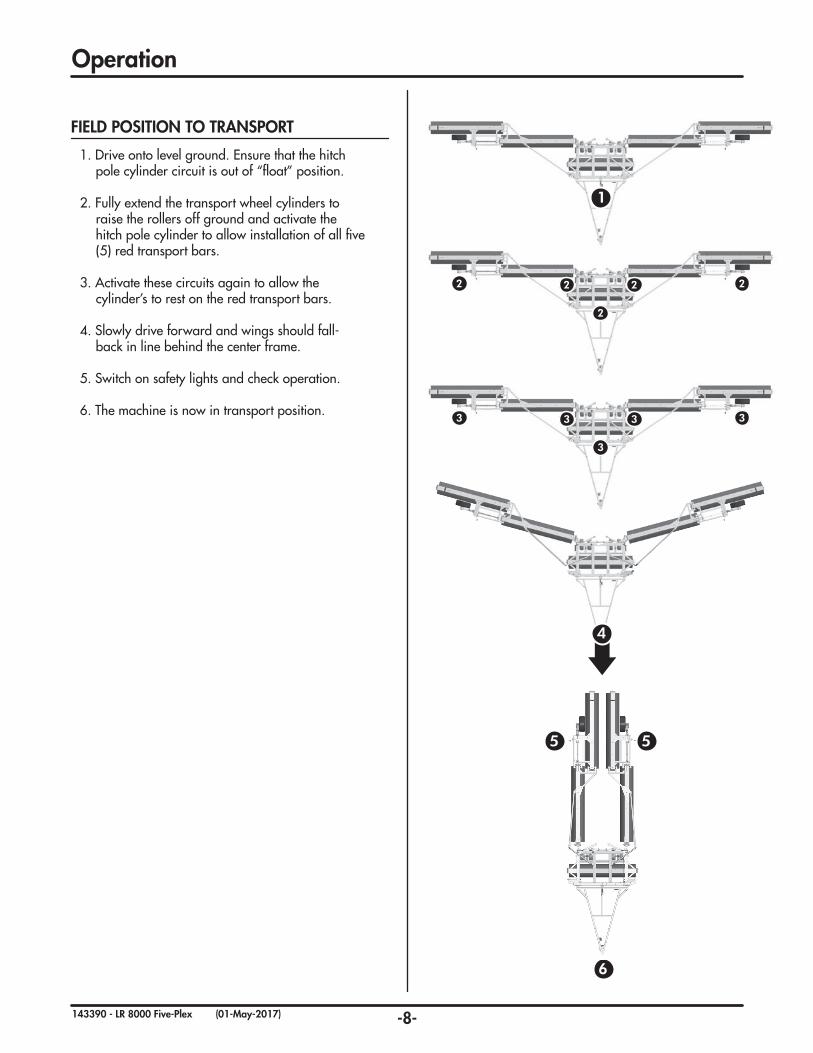
1. Drive onto level ground. Ensure that the hitch pole cylinder circuit is out of “float” position.
2. Fully extend the transport wheel cylinders to raise the rollers off ground and activate the hitch pole cylinder to allow installation of all five (5) red transport bars.
3. Activate these circuits again to allow the cylinder’s to rest on the red transport bars.
4. Slowly drive forward and wings should fall-back in line behind the center frame.
5. Switch on safety lights and check operation.
6. The machine is now in transport position.
FIELD POSITION TO TRANSPORT
-9-143390 - LR 8000 Five-Plex (01-May-2017)
Operation
1. Read and understand ALL the information in the Operator’s Manual regarding procedures and SAFETY when operating the Landroller in the field/yard or on the road.
2. Check with local authorities regarding machine transport on public roads. Obey all applicable laws and regulations.
3. Always travel at a safe speed. Use caution when making corners or meeting traffic.
4. Make sure the SMV (Slow Moving Vehicle) emblem and all the lights and reflectors that are required by the local highway and transport authorities are in place, are clean and can be seen clearly by all overtaking and oncoming traffic.
5. Keep to the right and yield the right-of-way to allow faster traffic to pass. Drive on the road shoulder, if permitted by law.
6. Always use hazard warning flashers on tractor when transporting unless prohibited by law.
7. Always use a pin with provisions for a mechanical retainer and a safety chain when attaching to a tractor or towing vehicle.
TRANSPORT SAFETY
Use the following guidelines while transporting the Landroller:
1. Use a safety chain.
2. Ensure all transport locks are securely in place.
3. Be sure hazard lights are flashing and SMV decal is visible.
4. MAXIMUM RECOMMENDED TRANSPORT SPEED: 30 km/h or 19 mph. (Road Conditions. Field speeds may be lower.)
IMPORTANT: UNDER NO CIRCUMSTANCES SHOULD THERE EVER BE RIDERS WHILE THE LANDROLLER IS IN TRANSPORT.
TRANSPORTING
NORIDERS
-10-143390 - LR 8000 Five-Plex (01-May-2017)
1. Review the Operator’s Manual and all safety items before working with, maintaining or operating the Landroller.
2. Stop the tractor engine, set park brake, remove ignition key and wait for all moving parts to stop before servicing, adjusting, repairing or unplugging.
3. Keep hands, feet, clothing and hair away from all moving and/or rotating parts.
4. Clear the area of bystanders, especially children, when carrying out any maintenance and repairs or making any adjustments.
5. Place safety stands or large blocks under the frame before removing tires or working beneath the machine.
6. Be careful when working around or maintaining a high-pressure hydraulic system. Wear proper eye and hand protection when searching for a high pressure hydraulic leak. Use a piece of wood or cardboard as a backstop when searching for a pin hole leak in a hose or a fitting.
7. Always relieve pressure before disconnecting or working on hydraulic system.
MAINTENANCE SAFETY
Service & Maintenance
MAINTENANCE CHECKLIST
(Note: Do NOT grease the spherical bearings)
Maintenance Check - 10 Hours
• Hydraulic fluid leaks
• Damaged hoses
• Check tire pressure: Front: 12.5L x 15 - 90 PSI (620 kPa)
Rear Tires: 385/65R - 90 PSI (620 kPa)
Grease Points - 25 Hours
• Front Hitch Frame Pins
• Swing-Arm Holders
• Cylinder Pins
• Spreader-Arm Pins
• Cast Bearings (not spherical bearings)
• Cross Joint Pins
• Wing Joint Pins
• Transport Wheel Arm Holders
• Transport Wheel Pins
• Hubs & Spindles
Grease Points - 50 Hours
• Working points & pins
• Safety signs clean
Annually
• Bolt tightness
• Wheel bearings
• Latch mechanism
• Cable assembly
Use the Maintenance Checklist provided for regular service intervals and keep a record of all scheduled maintenance:
-11-143390 - LR 8000 Five-Plex (01-May-2017)
Service & Maintenance
GREASING
Grease: Use an SAE multipurpose grease with extreme pressure (EP) performance. Also acceptable is an SAE multipurpose lithium.
1. Use only a hand-held grease gun for all greasing.
2. Wipe grease fitting with a clean cloth before greasing, to avoid injecting dirt.
3. Replace and repair broken fittings immediately.
4. If fittings will not take grease, remove and clean thoroughly. Also clean lubricant passageway. Replace fitting if necessary.
5. Inject grease until you see grease being expelled from the bearing or bushing areas.
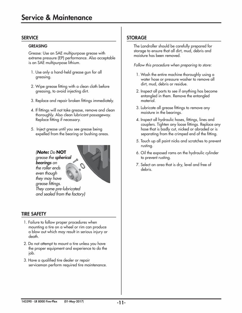
(Note: Do NOT grease the spherical bearings on the roller ends even though they may have grease fittings. They come pre-lubricated and sealed from the factory)
SERVICE
1. Failure to follow proper procedures when mounting a tire on a wheel or rim can produce a blow out which may result in serious injury or death.
2. Do not attempt to mount a tire unless you have the proper equipment and experience to do the job.
3. Have a qualified tire dealer or repair serviceman perform required tire maintenance.
TIRE SAFETY
The Landroller should be carefully prepared for storage to ensure that all dirt, mud, debris and moisture has been removed.
Follow this procedure when preparing to store:
1. Wash the entire machine thoroughly using a water hose or pressure washer to remove all dirt, mud, debris or residue.
2. Inspect all parts to see if anything has become entangled in them. Remove the entangled material.
3. Lubricate all grease fittings to remove any moisture in the bearings.
4. Inspect all hydraulic hoses, fittings, lines and couplers. Tighten any loose fittings. Replace any hose that is badly cut, nicked or abraded or is separating from the crimped end of the fitting.
5. Touch up all paint nicks and scratches to prevent rusting.
6. Oil the exposed rams on the hydraulic cylinder to prevent rusting.
7. Select an area that is dry, level and free of debris.
STORAGE
-12-143390 - LR 8000 Five-Plex (01-May-2017)
HYDRAULIC HOSE SPECIFICATIONS
Note: Unless otherwise stated, Hydraulic Hoses are either 3/8 or 1/2 with 3/4 JIC female swivel ends.
• Make sure that all components in the hydraulic system are kept in good condition and are clean.
• Replace any worn, cut, abraded, fl attened or crimped hoses and metal lines.
• Do not attempt any makeshift repairs to the hydraulic lines, fi ttings or hoses by using tape, clamps or cements. The hydraulic system operates under extremely high-pressure. Such repairs will fail suddenly and create a hazardous and unsafe condition.
• Wear proper hand and eye protection when searching for a high-pressure hydraulic leak. Use a piece of wood or cardboard as a backstop instead of hands to isolate and identify a leak.
• If injured by a concentrated high-pressure stream of hydraulic fl uid, seek medical attention immediately. Serious infection or toxic reaction can develop from hydraulic fl uid piercing the skin surface.
• Before applying pressure to the system, make sure all components are tight and that lines, hoses and couplings are not damaged.
HYDRAULIC SAFETY
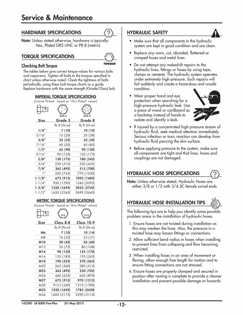
IMPERIAL TORQUE SPECIFICATIONS(Coarse Thread - based on “Zinc Plated” values)
SAE-5 SAE-8
Size Grade 5 Grade 8 lb.ft (N.m) lb.ft (N.m) 1/4” 7 (10) 10 (14) 5/16” 15 (20) 20 (28) 3/8” 25 (35) 35 (50) 7/16” 40 (55) 60 (80) 1/2” 65 (90) 90 (120) 9/16” 90 (125) 130 (175) 5/8” 130 (175) 180 (245) 3/4” 230 (310) 320 (435) 7/8” 365 (495) 515 (700) 1” 550 (745) 770 (1050) 1-1/8” 675 (915) 1095 (1485) 1-1/4” 950 (1290) 1545 (2095) 1-3/8” 1250 (1695) 2025 (2745) 1-1/2” 1650 (2245) 2690 (3645)
METRIC TORQUE SPECIFICATIONS(Coarse Thread - based on “Zinc Plated” values)
8.8 10.9
Size Class 8.8 Class 10.9 lb.ft (N.m) lb.ft (N.m) M6 7 (10) 10 (14) M8 16 (22) 23 (31) M10 30 (42) 45 (60) M12 55 (75) 80 (108) M14 90 (120) 125 (170) M16 135 (185) 195 (265) M18 190 (255) 270 (365) M20 265 (360) 380 (515) M22 365 (495) 520 (705) M24 460 (625) 660 (895) M27 675 (915) 970 (1315) M30 915 (1240) 1310 (1780) M33 1250 (1695) 1785 (2420) M36 1600 (2175) 2290 (3110)
TORQUE SPECIFICATIONS
Checking Bolt TorqueThe tables below give correct torque values for various bolts and capscrews. Tighten all bolts to the torques specifi ed in chart unless otherwise noted. Check the tightness of bolts periodically, using these bolt torque charts as a guide. Replace hardware with the same strength (Grade/Class) bolt.
TORQUE
Note: Unless stated otherwise, hardware is typically: Hex, Plated GR5 UNC or P8.8 (metric)
HARDWARE SPECIFICATIONS
HYDRAULIC HOSE INSTALLATION TIPS
The following tips are to help you identify some possible problem areas in the installation of hydraulic hoses.
1. Ensure hoses are not twisted during installation as this may weaken the hose. Also, the pressure in a twisted hose may loosen fi ttings or connections.
2. Allow suffi cient bend radius in hoses when installing to prevent lines from collapsing and fl ow becoming restricted.
3. When installing hoses in an area of movement or fl exing, allow enough free length for motion and to ensure fi tting connections are not stressed.
4. Ensure hoses are properly clamped and secured in position after routing is complete to provide a cleaner installation and prevent possible damage or hazards.
v1.0
Service & Maintenance
-13-143390 - LR 8000 Five-Plex (01-May-2017)
Note: A DASH size refers to a diameter of a hose (inside) or of a tube (outside) measured in 1/16” increments. For example, a Hose specifi ed as dash 8 or -8 would
have an inside diameter of 8/16” or 1/2”.Alternatively, a Tube specifi ed as dash 8 or -8 would
have an outside diameter of 8/16” or 1/2”.
The following info is to help you identify and properly install some of our standard hydraulic fi ttings.
HYDRAULIC FITTING INSTALLATION
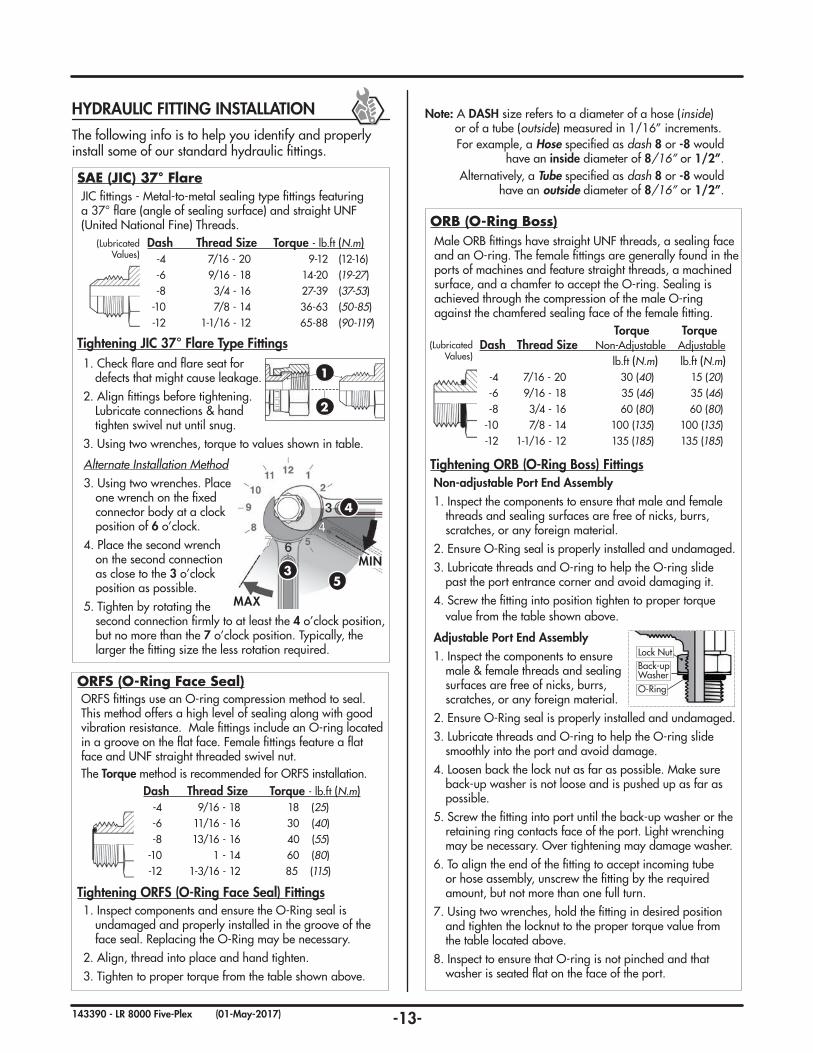
SAE (JIC) 37° Flare JIC fi ttings - Metal-to-metal sealing type fi ttings featuring a 37° fl are (angle of sealing surface) and straight UNF (United National Fine) Threads.
Alternate Installation Method 3. Using two wrenches. Place
one wrench on the fi xed connector body at a clock position of 6 o’clock.
4. Place the second wrench on the second connection as close to the 3 o’clock position as possible.
5. Tighten by rotating the second connection fi rmly to at least the 4 o’clock position,
but no more than the 7 o’clock position. Typically, the larger the fi tting size the less rotation required.
MAX
MIN
4
53
Tightening JIC 37° Flare Type Fittings1. Check fl are and fl are seat for
defects that might cause leakage.2. Align fi ttings before tightening.
Lubricate connections & hand tighten swivel nut until snug.
3. Using two wrenches, torque to values shown in table.
1
2
Dash Thread Size Torque - lb.ft (N.m) -4 7/16 - 20 9-12 (12-16) -6 9/16 - 18 14-20 (19-27) -8 3/4 - 16 27-39 (37-53) -10 7/8 - 14 36-63 (50-85) -12 1-1/16 - 12 65-88 (90-119)
(Lubricated Values)
Male ORB fi ttings have straight UNF threads, a sealing face and an O-ring. The female fi ttings are generally found in the ports of machines and feature straight threads, a machined surface, and a chamfer to accept the O-ring. Sealing is achieved through the compression of the male O-ring against the chamfered sealing face of the female fi tting.
Non-adjustable Port End Assembly1. Inspect the components to ensure that male and female
threads and sealing surfaces are free of nicks, burrs, scratches, or any foreign material.
2. Ensure O-Ring seal is properly installed and undamaged.3. Lubricate threads and O-ring to help the O-ring slide
past the port entrance corner and avoid damaging it. 4. Screw the fi tting into position tighten to proper torque
value from the table shown above.
Adjustable Port End Assembly1. Inspect the components to ensure
male & female threads and sealing surfaces are free of nicks, burrs, scratches, or any foreign material.
2. Ensure O-Ring seal is properly installed and undamaged.3. Lubricate threads and O-ring to help the O-ring slide
smoothly into the port and avoid damage.4. Loosen back the lock nut as far as possible. Make sure
back-up washer is not loose and is pushed up as far as possible.
5. Screw the fi tting into port until the back-up washer or the retaining ring contacts face of the port. Light wrenching may be necessary. Over tightening may damage washer.
6. To align the end of the fi tting to accept incoming tube or hose assembly, unscrew the fi tting by the required amount, but not more than one full turn.
7. Using two wrenches, hold the fi tting in desired position and tighten the locknut to the proper torque value from the table located above.
8. Inspect to ensure that O-ring is not pinched and that washer is seated fl at on the face of the port.
Tightening ORB (O-Ring Boss) Fittings
ORB (O-Ring Boss)
O-Ring
Lock NutBack-upWasher
Torque Torque Dash Thread Size Non-Adjustable Adjustable lb.ft (N.m) lb.ft (N.m) -4 7/16 - 20 30 (40) 15 (20) -6 9/16 - 18 35 (46) 35 (46) -8 3/4 - 16 60 (80) 60 (80) -10 7/8 - 14 100 (135) 100 (135) -12 1-1/16 - 12 135 (185) 135 (185)
(Lubricated Values)
ORFS fi ttings use an O-ring compression method to seal. This method offers a high level of sealing along with good vibration resistance. Male fi ttings include an O-ring located in a groove on the fl at face. Female fi ttings feature a fl at face and UNF straight threaded swivel nut. The Torque method is recommended for ORFS installation.
1. Inspect components and ensure the O-Ring seal is undamaged and properly installed in the groove of the face seal. Replacing the O-Ring may be necessary.
2. Align, thread into place and hand tighten.3. Tighten to proper torque from the table shown above.
Tightening ORFS (O-Ring Face Seal) Fittings
ORFS (O-Ring Face Seal)
Dash Thread Size Torque - lb.ft (N.m) -4 9/16 - 18 18 (25) -6 11/16 - 16 30 (40) -8 13/16 - 16 40 (55) -10 1 - 14 60 (80) -12 1-3/16 - 12 85 (115)
-14-143390 - LR 8000 Five-Plex (01-May-2017)
Service & Maintenance
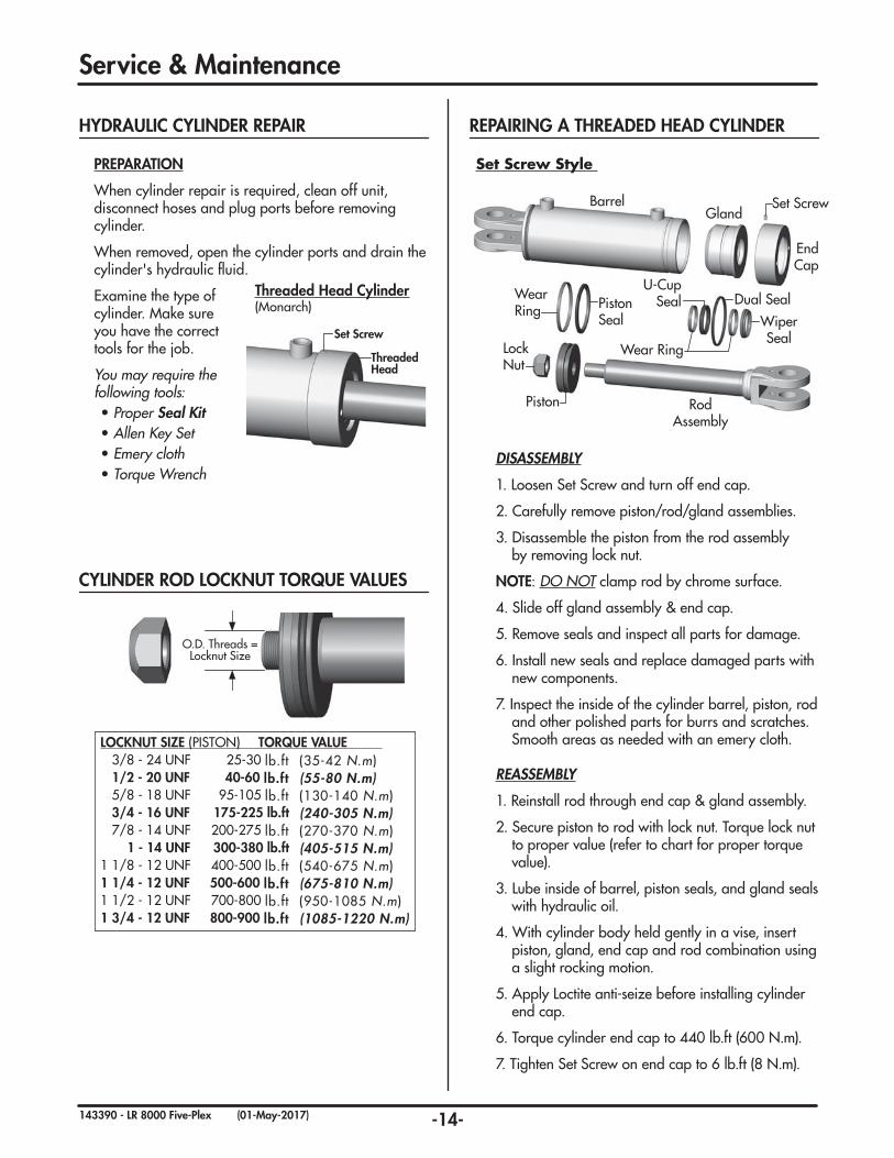
PREPARATION
When cylinder repair is required, clean off unit, disconnect hoses and plug ports before removing cylinder.
When removed, open the cylinder ports and drain the cylinder's hydraulic fl uid.
Examine the type of cylinder. Make sure you have the correct tools for the job.
You may require the following tools: • Proper Seal Kit• Allen Key Set • Emery cloth• Torque Wrench
Set Screw
Threaded Head
Threaded Head Cylinder (Monarch)
REPAIRING A THREADED HEAD CYLINDER
Barrel
RodAssembly
Lock Nut
Gland
End Cap
Set Screw
Piston Seal
Dual Seal
Wiper Seal
U-Cup SealWear
Ring
Wear Ring
Piston
DISASSEMBLY
1. Loosen Set Screw and turn off end cap.
2. Carefully remove piston/rod/gland assemblies.
3. Disassemble the piston from the rod assembly by removing lock nut.
NOTE: DO NOT clamp rod by chrome surface.
4. Slide off gland assembly & end cap.
5. Remove seals and inspect all parts for damage.
6. Install new seals and replace damaged parts with new components.
7. Inspect the inside of the cylinder barrel, piston, rod and other polished parts for burrs and scratches. Smooth areas as needed with an emery cloth.
REASSEMBLY
1. Reinstall rod through end cap & gland assembly.
2. Secure piston to rod with lock nut. Torque lock nut to proper value (refer to chart for proper torque value).
3. Lube inside of barrel, piston seals, and gland seals with hydraulic oil.
4. With cylinder body held gently in a vise, insert piston, gland, end cap and rod combination using a slight rocking motion.
5. Apply Loctite anti-seize before installing cylinder end cap.
6. Torque cylinder end cap to 440 lb.ft (600 N.m).
7. Tighten Set Screw on end cap to 6 lb.ft (8 N.m).
Set Screw Style
HYDRAULIC CYLINDER REPAIR
LOCKNUT SIZE (PISTON) TORQUE VALUE 3/8 - 24 UNF 25-30 lb.ft (35-42 N.m) 1/2 - 20 UNF 40-60 lb.ft (55-80 N.m) 5/8 - 18 UNF 95-105 lb.ft (130-140 N.m) 3/4 - 16 UNF 175-225 lb.ft (240-305 N.m) 7/8 - 14 UNF 200-275 lb.ft (270-370 N.m) 1 - 14 UNF 300-380 lb.ft (405-515 N.m)1 1/8 - 12 UNF 400-500 lb.ft (540-675 N.m)1 1/4 - 12 UNF 500-600 lb.ft (675-810 N.m)1 1/2 - 12 UNF 700-800 lb.ft (950-1085 N.m)1 3/4 - 12 UNF 800-900 lb.ft (1085-1220 N.m)
O.D. Threads = Locknut Size
CYLINDER ROD LOCKNUT TORQUE VALUES
-15-143390 - LR 8000 Five-Plex (01-May-2017)
Service & Maintenance
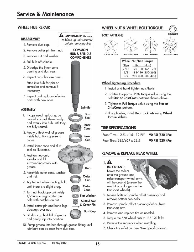
WHEEL HUB REPAIR
DISASSEMBLY
1. Remove dust cap.
2. Remove cotter pin from nut.
3. Remove nut and washer.
4. Pull hub off spindle.
5. Dislodge the inner cone bearing and dust seal.
6. Inspect cups that are press
fitted into hub for pits or corrosion and remove if necessary.
7. Inspect and replace defective parts with new ones.
ASSEMBLY
1. If cups need replacing, be careful to install them gently and evenly into hub until they are fully seated.
2. Apply a thick wall of grease inside hub. Pack grease in cones.
3. Install inner cone and dust seal as illustrated.
4. Position hub onto spindle and fill surrounding cavity with grease.
5. Assemble outer cone, washer and nut.
6. Tighten nut while rotating hub until there is a slight drag.
7. Turn nut back approximately 1/2 turn to align cotter pin hole with notches on nut.
8. Install cotter pin and bend legs sideways over nut.
9. Fill dust cap half full of grease and gently tap into position.
10. Pump grease into hub through grease fitting until lubricant can be seen from dust seal.
COMMON HUB & SPINDLE COMPONENTS
Dust Seal
Inner Cone
Inner Cup
Hub
Outer Cup
Outer Cone
Flat Washer
Slotted Nut & Cotter Pin
Dust Cap
Spindle
IMPORTANT: Be sure to block up unit securely
before removing tires.
Wheel Tightening Procedure
1. Install and hand tighten nuts/bolts.
2. Tighten to approx. 20% Torque value using the Bolt Star or CrissCross patterns shown above.
3. Tighten to Full Torque value using the Star or CrissCross pattern.
4. If applicable, install Rear Locknuts using Wheel Torque Values.
Wheel Nut/Bolt Torque Size lb.ft (N.m) 9/16 120-130 (165-175) 5/8 185-190 (250-260) 3/4 280-300 (380-405)
BOLT PATTERNS
2
1
6
5 3
4
6 BOLT PATTERN2
1
3 4
5 7
8
8 BOLT PATTERN
1
2
3 4
55 BOLT PATTERN
1
2
3
46
5
7 9
10 8
10 BOLT PATTERN
WHEEL NUT & WHEEL BOLT TORQUETORQUE
REMOVE & REPLACE REAR WHEEL
1. IMPORTANT: Lower the rollers onto the ground and raise transport wheel arms off the ground (ensure the weight is no longer on the transport wheels).
2. Loosen bolts on spindle offset assembly and remove bottom two bolts.
3. Remove spindle offset assembly/wheel from transport arm.
4. Remove and replace tire as needed.
5. Torque the 5/8 wheel nuts to 185-190 ft·lbs.
6. Reverse the sequence when installing.
7. Check tire inflation. See “Tire Specifications”.
TIRE SPECIFICATIONS
Front Tires: 12.5L x 15 - 12 PLY 90 PSI (620 kPa)
Rear Tires: 385/65R x 22.5 90 PSI (620 kPa)
-16-143390 - LR 8000 Five-Plex (01-May-2017)
Service & Maintenance
BearingSnap RingLock
WasherLock Nut
Snap RingAdapter Sleeve.
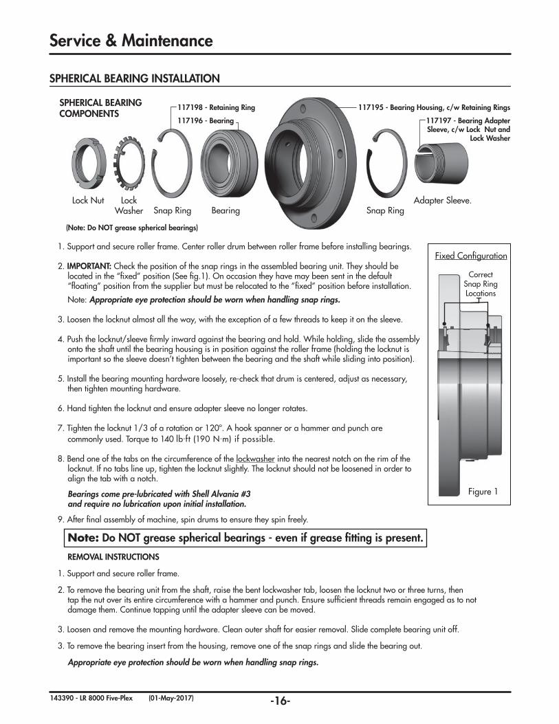
SPHERICAL BEARING COMPONENTS
Correct Snap Ring Locations
Fixed Configuration
Figure 1
SPHERICAL BEARING INSTALLATION
1. Support and secure roller frame. Center roller drum between roller frame before installing bearings.
2. IMPORTANT: Check the position of the snap rings in the assembled bearing unit. They should be located in the “fixed” position (See fig.1). On occasion they have may been sent in the default “floating” position from the supplier but must be relocated to the ”fixed” position before installation.
Note: Appropriate eye protection should be worn when handling snap rings.
3. Loosen the locknut almost all the way, with the exception of a few threads to keep it on the sleeve.
4. Push the locknut/sleeve firmly inward against the bearing and hold. While holding, slide the assembly onto the shaft until the bearing housing is in position against the roller frame (holding the locknut is important so the sleeve doesn’t tighten between the bearing and the shaft while sliding into position).
5. Install the bearing mounting hardware loosely, re-check that drum is centered, adjust as necessary, then tighten mounting hardware.
6. Hand tighten the locknut and ensure adapter sleeve no longer rotates.
7. Tighten the locknut 1/3 of a rotation or 120º. A hook spanner or a hammer and punch are commonly used. Torque to 140 lb.ft (190 N.m) if possible.
8. Bend one of the tabs on the circumference of the lockwasher into the nearest notch on the rim of the locknut. If no tabs line up, tighten the locknut slightly. The locknut should not be loosened in order to align the tab with a notch.
Bearings come pre-lubricated with Shell Alvania #3 and require no lubrication upon initial installation.
9. After final assembly of machine, spin drums to ensure they spin freely.
Note: Do NOT grease spherical bearings - even if grease fitting is present.
REMOVAL INSTRUCTIONS
1. Support and secure roller frame.
2. To remove the bearing unit from the shaft, raise the bent lockwasher tab, loosen the locknut two or three turns, then tap the nut over its entire circumference with a hammer and punch. Ensure sufficient threads remain engaged as to not damage them. Continue tapping until the adapter sleeve can be moved.
3. Loosen and remove the mounting hardware. Clean outer shaft for easier removal. Slide complete bearing unit off.
3. To remove the bearing insert from the housing, remove one of the snap rings and slide the bearing out.
Appropriate eye protection should be worn when handling snap rings.
117196 - Bearing
117198 - Retaining Ring
117197 - Bearing Adapter Sleeve, c/w Lock Nut and
Lock Washer
117195 - Bearing Housing, c/w Retaining Rings
(Note: Do NOT grease spherical bearings)
-17-143390 - LR 8000 Five-Plex (01-May-2017)
10
1181
2
3 9
4
5
6
7
12
105
5
511
4
4
3
9
8
21
9
12
4
2
6
7
66
77
5
5
5
9
Service & Maintenance
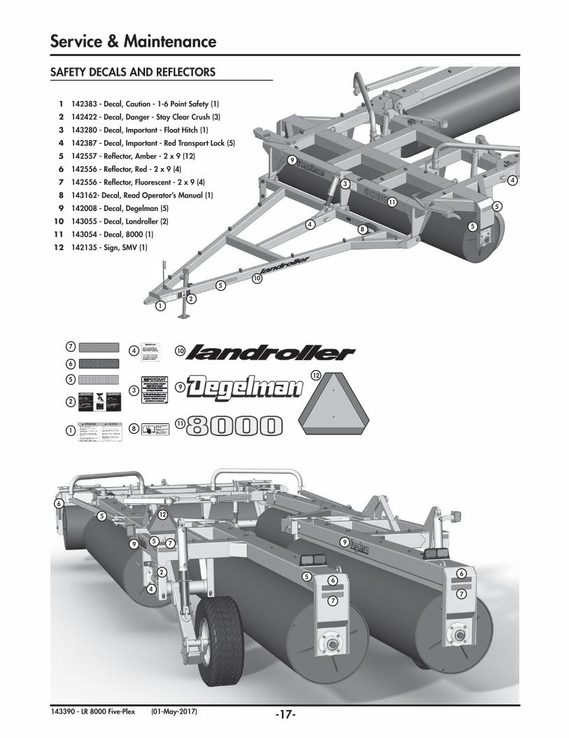
SAFETY DECALS AND REFLECTORS
1 142383 - Decal, Caution - 1-6 Point Safety (1)
2 142422 - Decal, Danger - Stay Clear Crush (3)
3 143280 - Decal, Important - Float Hitch (1)
4 142387 - Decal, Important - Red Transport Lock (5)
5 142557 - Reflector, Amber - 2 x 9 (12)
6 142556 - Reflector, Red - 2 x 9 (4)
7 142556 - Reflector, Fluorescent - 2 x 9 (4)
8 143162- Decal, Read Operator’s Manual (1)
9 142008 - Decal, Degelman (5)
10 143055 - Decal, Landroller (2)
11 143054 - Decal, 8000 (1)
12 142135 - Sign, SMV (1)
-18-143390 - LR 8000 Five-Plex (01-May-2017)
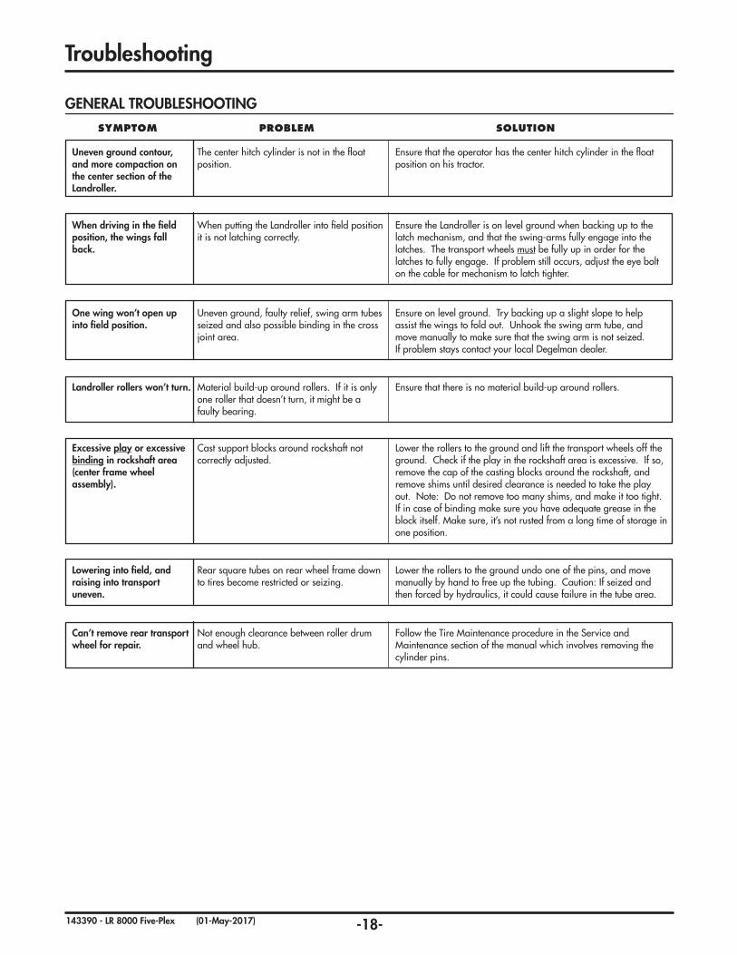
Troubleshooting
Uneven ground contour, and more compaction on the center section of the Landroller.
The center hitch cylinder is not in the float position.
Ensure that the operator has the center hitch cylinder in the float position on his tractor.
GENERAL TROUBLESHOOTING
SYMPTOM PROBLEM SOLUTION
Landroller rollers won’t turn. Material build-up around rollers. If it is only one roller that doesn’t turn, it might be a faulty bearing.
Ensure that there is no material build-up around rollers.
Excessive play or excessive binding in rockshaft area(center frame wheel assembly).
Cast support blocks around rockshaft not correctly adjusted.
Lower the rollers to the ground and lift the transport wheels off the ground. Check if the play in the rockshaft area is excessive. If so, remove the cap of the casting blocks around the rockshaft, and remove shims until desired clearance is needed to take the play out. Note: Do not remove too many shims, and make it too tight. If in case of binding make sure you have adequate grease in the block itself. Make sure, it’s not rusted from a long time of storage in one position.
When driving in the field position, the wings fall back.
When putting the Landroller into field position it is not latching correctly.
Ensure the Landroller is on level ground when backing up to the latch mechanism, and that the swing-arms fully engage into the latches. The transport wheels must be fully up in order for the latches to fully engage. If problem still occurs, adjust the eye bolt on the cable for mechanism to latch tighter.
One wing won’t open up into field position.
Uneven ground, faulty relief, swing arm tubes seized and also possible binding in the cross joint area.
Ensure on level ground. Try backing up a slight slope to help assist the wings to fold out. Unhook the swing arm tube, and move manually to make sure that the swing arm is not seized. If problem stays contact your local Degelman dealer.
Lowering into field, and raising into transport uneven.
Rear square tubes on rear wheel frame down to tires become restricted or seizing.
Lower the rollers to the ground undo one of the pins, and move manually by hand to free up the tubing. Caution: If seized and then forced by hydraulics, it could cause failure in the tube area.
Can’t remove rear transport wheel for repair.
Not enough clearance between roller drum and wheel hub.
Follow the Tire Maintenance procedure in the Service and Maintenance section of the manual which involves removing the cylinder pins.
-19-143390 - LR 8000 Five-Plex (11-September-2017)
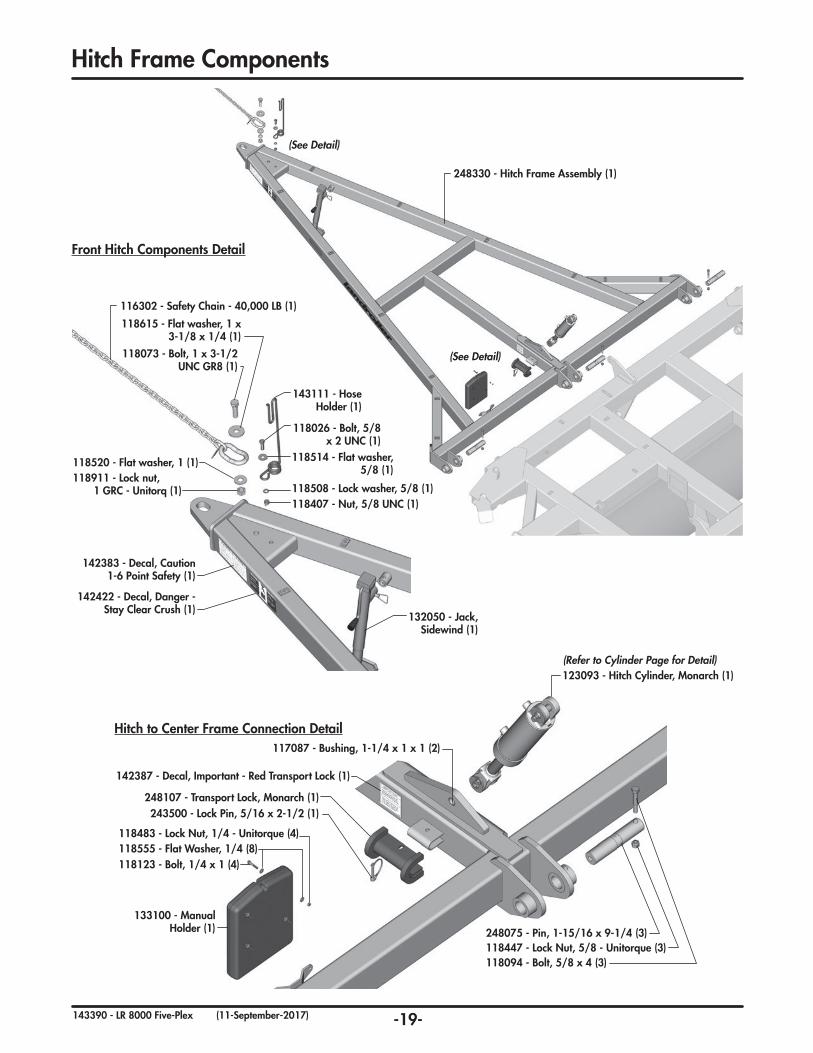
248330 - Hitch Frame Assembly (1)
(See Detail)
(See Detail)
132050 - Jack, Sidewind (1)
118615 - Flat washer, 1 x 3-1/8 x 1/4 (1)
118911 - Lock nut,1 GRC - Unitorq (1)
118073 - Bolt, 1 x 3-1/2 UNC GR8 (1)
118514 - Flat washer, 5/8 (1)
118508 - Lock washer, 5/8 (1)118407 - Nut, 5/8 UNC (1)
118026 - Bolt, 5/8 x 2 UNC (1)
143111 - Hose Holder (1)
118520 - Flat washer, 1 (1)
116302 - Safety Chain - 40,000 LB (1)
Front Hitch Components Detail
117087 - Bushing, 1-1/4 x 1 x 1 (2)
142387 - Decal, Important - Red Transport Lock (1)
123093 - Hitch Cylinder, Monarch (1)
243500 - Lock Pin, 5/16 x 2-1/2 (1)
118483 - Lock Nut, 1/4 - Unitorque (4)118555 - Flat Washer, 1/4 (8)118123 - Bolt, 1/4 x 1 (4)
118447 - Lock Nut, 5/8 - Unitorque (3)118094 - Bolt, 5/8 x 4 (3)
133100 - Manual Holder (1) 248075 - Pin, 1-15/16 x 9-1/4 (3)
(Refer to Cylinder Page for Detail)
Hitch to Center Frame Connection Detail
142383 - Decal, Caution 1-6 Point Safety (1)
142422 - Decal, Danger - Stay Clear Crush (1)
248107 - Transport Lock, Monarch (1)
Hitch Frame Components
-20-143390 - LR 8000 Five-Plex (01-May-2017)
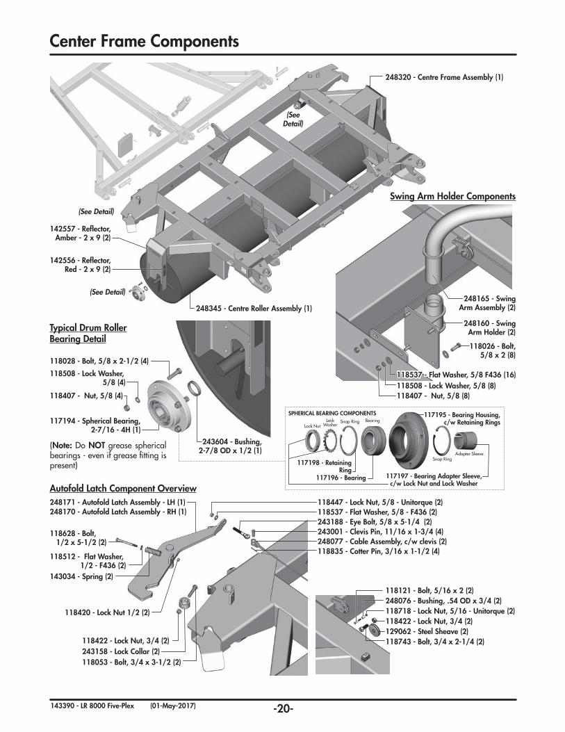
248320 - Centre Frame Assembly (1)
248345 - Centre Roller Assembly (1)
(See Detail)
(See Detail)
(See Detail)
142556 - Reflector, Red - 2 x 9 (2)
142557 - Reflector, Amber - 2 x 9 (2)
243604 - Bushing, 2-7/8 OD x 1/2 (1)
118407 - Nut, 5/8 (4)
118508 - Lock Washer,5/8 (4)
118028 - Bolt, 5/8 x 2-1/2 (4)
117194 - Spherical Bearing, 2-7/16 - 4H (1)
(Note: Do NOT grease spherical bearings - even if grease fitting is present)
Typical Drum RollerBearing Detail
BearingSnap RingLock WasherLock Nut
Snap RingAdapter Sleeve.
SPHERICAL BEARING COMPONENTS
117196 - Bearing
117198 - Retaining Ring
117197 - Bearing Adapter Sleeve, c/w Lock Nut and Lock Washer
117195 - Bearing Housing, c/w Retaining Rings
248165 - Swing Arm Assembly (2)
118407 - Nut, 5/8 (8)118508 - Lock Washer, 5/8 (8)
118026 - Bolt, 5/8 x 2 (8)
118537 - Flat Washer, 5/8 F436 (16)
248160 - Swing Arm Holder (2)
Swing Arm Holder Components
118447 - Lock Nut, 5/8 - Unitorque (2)118537 - Flat Washer, 5/8 - F436 (2)243188 - Eye Bolt, 5/8 x 5-1/4 (2)243001 - Clevis Pin, 11/16 x 1-3/4 (4)248077 - Cable Assembly, c/w clevis (2)118835 - Cotter Pin, 3/16 x 1-1/2 (4)
118422 - Lock Nut, 3/4 (2)129062 - Steel Sheave (2)118743 - Bolt, 3/4 x 2-1/4 (2)
118718 - Lock Nut, 5/16 - Unitorque (2)248076 - Bushing, .54 OD x 3/4 (2)118121 - Bolt, 5/16 x 2 (2)
248171 - Autofold Latch Assembly - LH (1)248170 - Autofold Latch Assembly - RH (1)
243158 - Lock Collar (2)118053 - Bolt, 3/4 x 3-1/2 (2)
118422 - Lock Nut, 3/4 (2)
143034 - Spring (2)
118420 - Lock Nut 1/2 (2)
118512 - Flat Washer, 1/2 - F436 (2)
118628 - Bolt, 1/2 x 5-1/2 (2)
Autofold Latch Component Overview
Center Frame Components
-21-143390 - LR 8000 Five-Plex (01-June-2017)
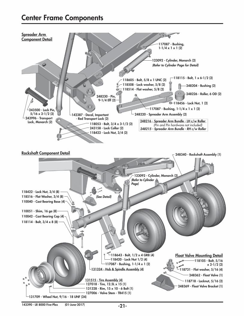
Spreader Arm Component Detail
Rockshaft Component Detail
123092 - Cylinder, Monarch (2)(Refer to Cylinder Page)
118422 - Lock Nut, 3/4 (8)118516 - Flat Washer, 3/4 (8)
118114 - Bolt, 3/4 x 8 (8)
110051 - Shim, 16 ga (8)
110040 - Cast Bearing Base (4)
110042 - Cast Bearing Cap (4)
117087 - Bushing, 1-1/4 x 1 (2)118420 - Lock Nut 1/2 (4)118643 - Bolt, 1/2 x 4 GR8 (4)
248340 - Rockshaft Assembly (1)
131324 - Hub & Spindle Assembly (4)
131515 - Tire Assembly (4)127018 - Tire, 12.5L x 15 (1)131328 - Rim, 15 x 10 - 6 Bolt (1)127006 - Valve Stem - TR415 (1)
131709 - Wheel Nut, 9/16 - 18 UNF (24)
(See Detail)
Float Valve Mounting Detail118105 - Bolt, 5/16
x 2-1/2 (2)118731 - Flat washer, 5/16 (4)
248362 - Float Valve (1)
118718 - Locknut, 5/16 (2)
248369 - Float Valve Bracket (1)
123092 - Cylinder, Monarch (2)(Refer to Cylinder Page for Detail)
117087 - Bushing, 1-1/4 x 1 x 1 (2)
248220 - Spreader Arm Assembly (2)
118115 - Bolt, 1 x 6-1/2 (2)
248226 - Roller, 6 OD (2)
248204 - Bushing (2)
118456 - Lock Nut, 1 (2)
248216 - Spreader Arm Bundle - LH c/w Roller
248215 - Spreader Arm Bundle - RH c/w Roller
118514 - Flat washer, 5/8 (2)118508 - Lock washer, 5/8 (2)118605 - Bolt, 5/8 x 1 UNC (2)
248230 - Pin, 9-1/4 Eff (2)
(Pin and Pin hardware not included)243158 - Lock Collar (2)118053 - Bolt, 3/4 x 3-1/2 (2)
118422 - Lock Nut, 3/4 (2)
243996 - Transport Lock, Monarch (2)
142387 - Decal, Important - Red Transport Lock (2)
117087 - Bushing, 1-1/4 x 1 x 1 (2)
243500 - Lock Pin, 5/16 x 2-1/2 (2)
Center Frame Components

-22-143390 - LR 8000 Five-Plex (01-May-2017)
Inner Wing Frame Component Overview
248306 - Inner Wing Frame Assembly - 80 ft - LH (1)
248305 - Inner Wing Frame Assembly - 80 ft - RH (1)
248315 - Inner Wing Frame Assembly - 64 ft - LH (1)
248314 - Inner Wing Frame Assembly - 64 ft - RH (1)
248155 - Truss Arm Assembly (2)
(See Cross Joint Detail)
(See Detail)
(See Detail)
118422 - Lock Nut, 3/4 (4)
118193 - Bolt, 3/4 x 5 GR8 (4)
248145 - Cross Joint Pin (4)
248140 - Cross Joint Assembly (2)
Cross Joint Detail
118391 - Bolt, 1-1/2 x 7 GR8 (2)
118694 - Lock Nut, 1-1/2 (4)
142557Reflector, Amber2 x 9 (2)
117145 - Bushing, 1-7/8 x 1-1/2 x 1 (4)
Truss Arm-Wing Connection Wing Connection Detail
248364 - Wing Pin 1-15/16 (4)
118605 - Bolt, 5/8 x 1 (2)
118508 - Lock Washer, 5/8 (2)
118514 - Flat Washer, 5/8 (2)
248210 - Pin Assembly, 5-5/8 eff (2)
243753 - Wing Roller Assembly - 80 ft (2)
248275 - Wing Roller Assembly - 64 ft (2)
118605 - Bolt, 5/8 x 1 (2)118508 - Lock Washer, 5/8 (2)
118514 - Flat Washer, 5/8 (2)
Inner Wing Frame Components
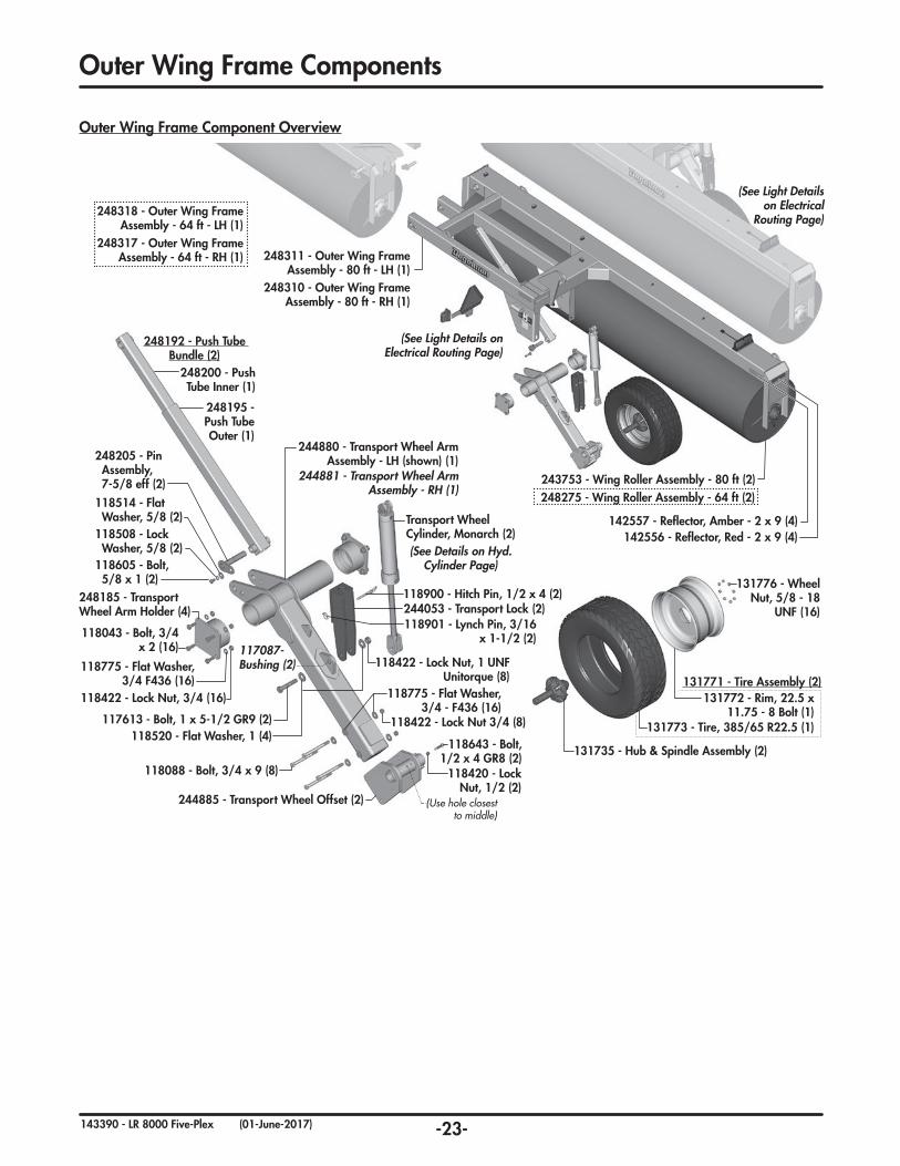
-23-143390 - LR 8000 Five-Plex (01-June-2017)
131776 - Wheel Nut, 5/8 - 18
UNF (16)
131773 - Tire, 385/65 R22.5 (1)
131735 - Hub & Spindle Assembly (2)
131772 - Rim, 22.5 x 11.75 - 8 Bolt (1)
131771 - Tire Assembly (2)
118605 - Bolt, 5/8 x 1 (2)
118508 - Lock Washer, 5/8 (2)
118514 - Flat Washer, 5/8 (2)
248205 - Pin Assembly, 7-5/8 eff (2)
248192 - Push Tube Bundle (2)
248200 - Push Tube Inner (1)
248195 - Push Tube Outer (1)
118643 - Bolt, 1/2 x 4 GR8 (2)
244881 - Transport Wheel Arm Assembly - RH (1)
118422 - Lock Nut 3/4 (8)
118088 - Bolt, 3/4 x 9 (8)
244885 - Transport Wheel Offset (2)
118775 - Flat Washer, 3/4 - F436 (16)
(Use hole closest to middle)
244880 - Transport Wheel Arm Assembly - LH (shown) (1)
118420 - Lock Nut, 1/2 (2)
248185 - Transport Wheel Arm Holder (4)
118775 - Flat Washer, 3/4 F436 (16)
118043 - Bolt, 3/4 x 2 (16)
117613 - Bolt, 1 x 5-1/2 GR9 (2)118520 - Flat Washer, 1 (4)
118422 - Lock Nut, 1 UNF Unitorque (8)
118900 - Hitch Pin, 1/2 x 4 (2)244053 - Transport Lock (2)118901 - Lynch Pin, 3/16
x 1-1/2 (2)
118422 - Lock Nut, 3/4 (16)
117087- Bushing (2)
Transport Wheel Cylinder, Monarch (2)(See Details on Hyd.
Cylinder Page)
Outer Wing Frame Component Overview
248311 - Outer Wing Frame Assembly - 80 ft - LH (1)
248310 - Outer Wing Frame Assembly - 80 ft - RH (1)
248318 - Outer Wing Frame Assembly - 64 ft - LH (1)
248317 - Outer Wing Frame Assembly - 64 ft - RH (1)
243753 - Wing Roller Assembly - 80 ft (2)
248275 - Wing Roller Assembly - 64 ft (2)
142556 - Reflector, Red - 2 x 9 (4)142557 - Reflector, Amber - 2 x 9 (4)
(See Light Details on Electrical Routing Page)
(See Light Details on Electrical
Routing Page)
Outer Wing Frame Components
-24-143390 - LR 8000 Five-Plex (01-May-2017)
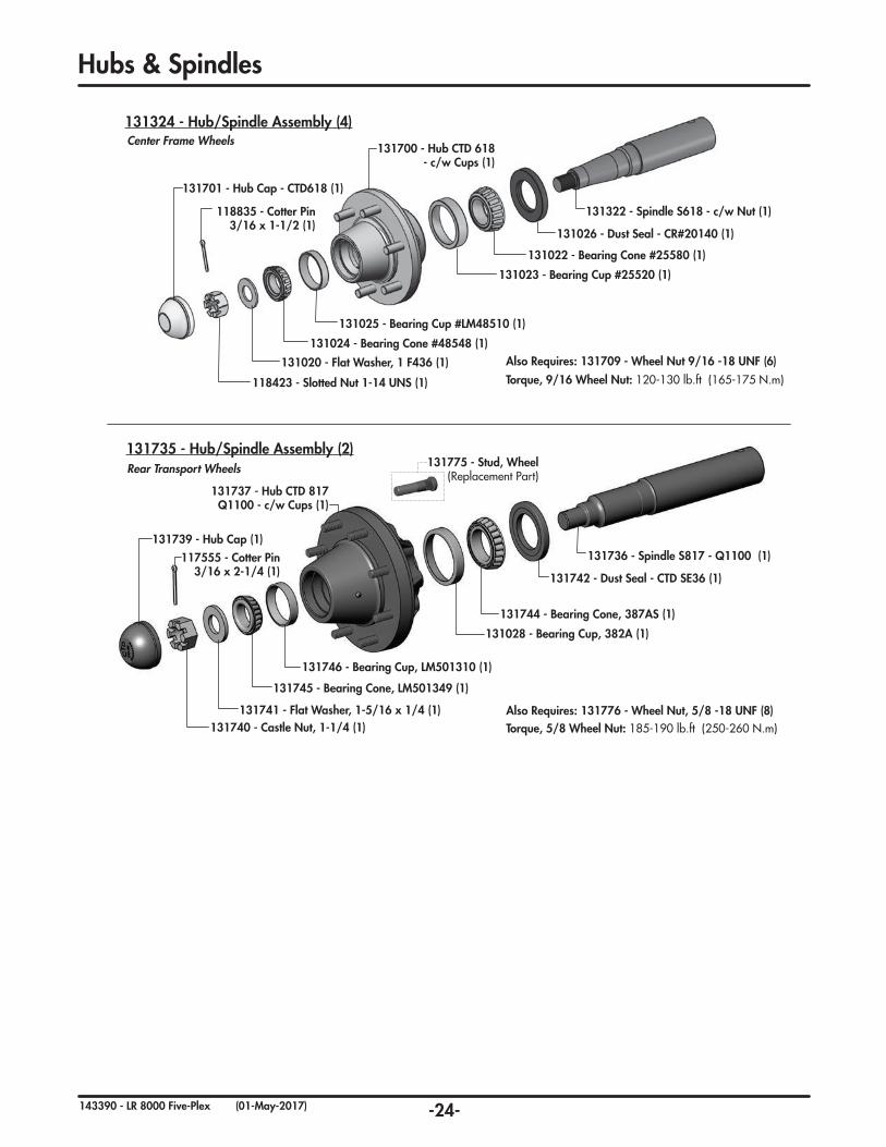
131701 - Hub Cap - CTD618 (1)
118835 - Cotter Pin 3/16 x 1-1/2 (1)
131700 - Hub CTD 618 - c/w Cups (1)
131324 - Hub/Spindle Assembly (4)
131020 - Flat Washer, 1 F436 (1)
131025 - Bearing Cup #LM48510 (1)
131024 - Bearing Cone #48548 (1)
118423 - Slotted Nut 1-14 UNS (1)
131023 - Bearing Cup #25520 (1)
131022 - Bearing Cone #25580 (1)
131026 - Dust Seal - CR#20140 (1)
131322 - Spindle S618 - c/w Nut (1)
131739 - Hub Cap (1)
131741 - Flat Washer, 1-5/16 x 1/4 (1)
131742 - Dust Seal - CTD SE36 (1)
131736 - Spindle S817 - Q1100 (1)
131775 - Stud, Wheel (Replacement Part)
131740 - Castle Nut, 1-1/4 (1)
131737 - Hub CTD 817 Q1100 - c/w Cups (1)
131735 - Hub/Spindle Assembly (2)
131028 - Bearing Cup, 382A (1)
131744 - Bearing Cone, 387AS (1)
131746 - Bearing Cup, LM501310 (1)
131745 - Bearing Cone, LM501349 (1)
Center Frame Wheels
Rear Transport Wheels
117555 - Cotter Pin 3/16 x 2-1/4 (1)
Also Requires: 131709 - Wheel Nut 9/16 -18 UNF (6)
Also Requires: 131776 - Wheel Nut, 5/8 -18 UNF (8)Torque, 5/8 Wheel Nut: 185-190 lb.ft (250-260 N.m)
Torque, 9/16 Wheel Nut: 120-130 lb.ft (165-175 N.m)
Hubs & Spindles
-25-143390 - LR 8000 Five-Plex (01-May-2017)
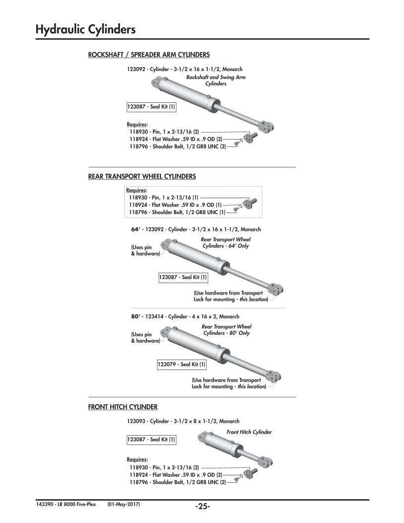
ROCKSHAFT / SPREADER ARM CYLINDERS
REAR TRANSPORT WHEEL CYLINDERS
FRONT HITCH CYLINDER
123093 - Cylinder - 3-1/2 x 8 x 1-1/2, Monarch
Front Hitch Cylinder
123092 - Cylinder - 3-1/2 x 16 x 1-1/2, Monarch
118924 - Flat Washer .59 ID x .9 OD (2)118796 - Shoulder Bolt, 1/2 GR8 UNC (2)
118930 - Pin, 1 x 2-13/16 (2)
118924 - Flat Washer .59 ID x .9 OD (2)118796 - Shoulder Bolt, 1/2 GR8 UNC (2)
118930 - Pin, 1 x 2-13/16 (2)
Requires:
Requires:
Rockshaft and Swing Arm Cylinders
123087 - Seal Kit (1)
123087 - Seal Kit (1)
Rear Transport Wheel Cylinders - 80’ Only
123079 - Seal Kit (1)
80’ - 123414 - Cylinder - 4 x 16 x 2, Monarch
(Use hardware from Transport Lock for mounting - this location)
(Uses pin & hardware)
64’ - 123092 - Cylinder - 3-1/2 x 16 x 1-1/2, Monarch
Rear Transport Wheel Cylinders - 64’ Only
123087 - Seal Kit (1)
(Use hardware from Transport Lock for mounting - this location)
(Uses pin & hardware)
118924 - Flat Washer .59 ID x .9 OD (1)118796 - Shoulder Bolt, 1/2 GR8 UNC (1)
118930 - Pin, 1 x 2-13/16 (1)Requires:
Hydraulic Cylinders
-26-143390 - LR 8000 Five-Plex (01-May-2017)
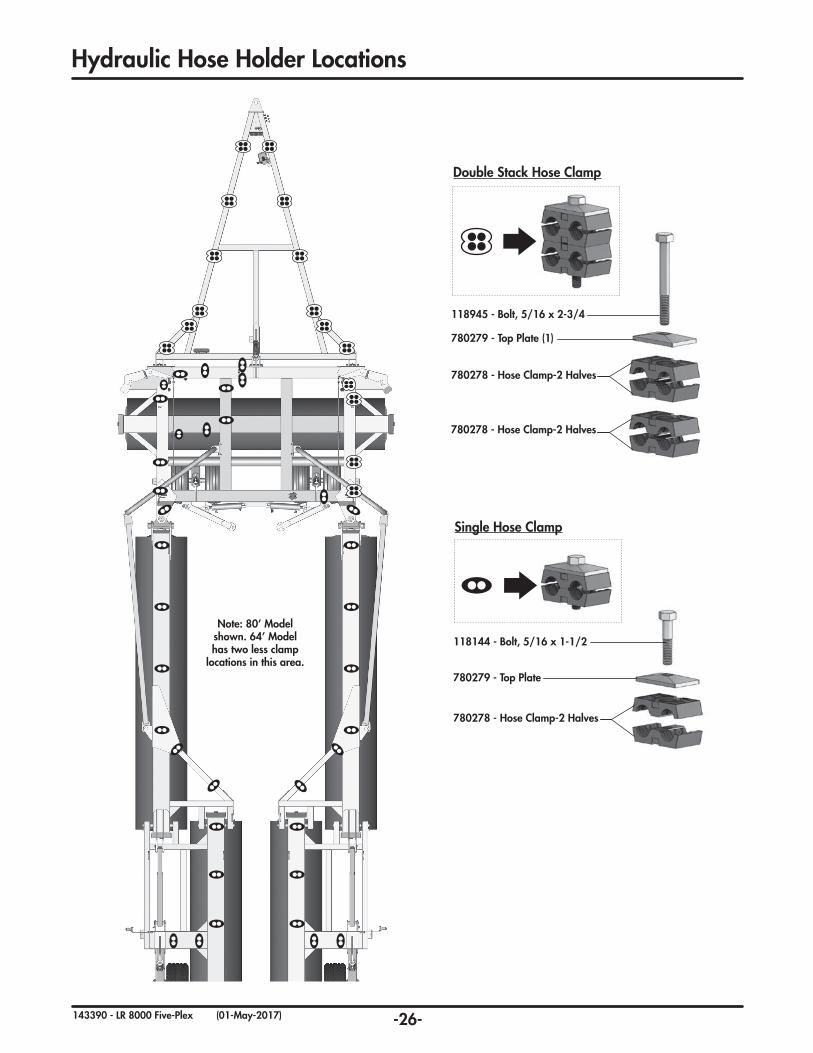
Note: 80’ Model shown. 64’ Model has two less clamp
locations in this area.
780278 - Hose Clamp-2 Halves
780278 - Hose Clamp-2 Halves
780279 - Top Plate (1)
118945 - Bolt, 5/16 x 2-3/4
780278 - Hose Clamp-2 Halves
780279 - Top Plate
118144 - Bolt, 5/16 x 1-1/2
Double Stack Hose Clamp
Single Hose Clamp
Hydraulic Hose Holder Locations
-27-143390 - LR 8000 Five-Plex (01-May-2017)
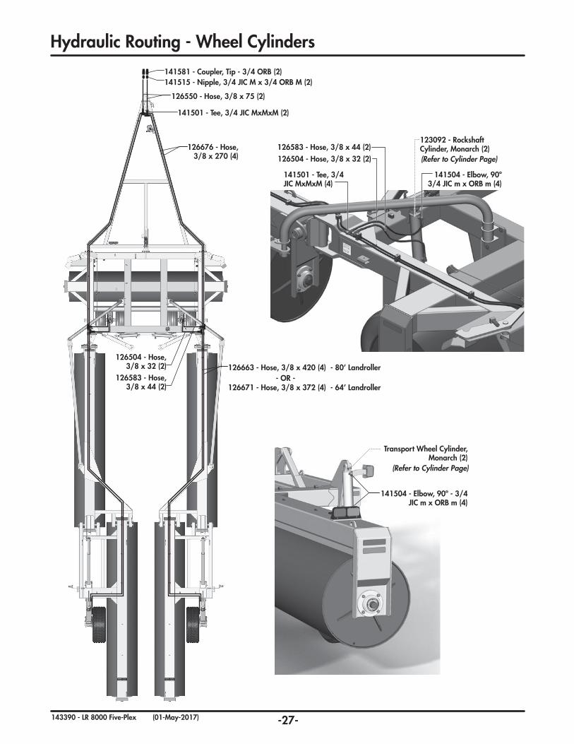
- OR -
141504 - Elbow, 90º - 3/4 JIC m x ORB m (4)
126550 - Hose, 3/8 x 75 (2)
126676 - Hose, 3/8 x 270 (4)
126663 - Hose, 3/8 x 420 (4) - 80’ Landroller
126671 - Hose, 3/8 x 372 (4) - 64’ Landroller
141501 - Tee, 3/4 JIC MxMxM (2)
126583 - Hose, 3/8 x 44 (2)
126504 - Hose, 3/8 x 32 (2)
141515 - Nipple, 3/4 JIC M x 3/4 ORB M (2) 141581 - Coupler, Tip - 3/4 ORB (2)
(Refer to Cylinder Page)
Transport Wheel Cylinder, Monarch (2)
126583 - Hose, 3/8 x 44 (2) 126504 - Hose, 3/8 x 32 (2)
141501 - Tee, 3/4 JIC MxMxM (4)
141504 - Elbow, 90º 3/4 JIC m x ORB m (4)
(Refer to Cylinder Page)
123092 - Rockshaft Cylinder, Monarch (2)
Hydraulic Routing - Wheel Cylinders
-28-143390 - LR 8000 Five-Plex (01-May-2017)
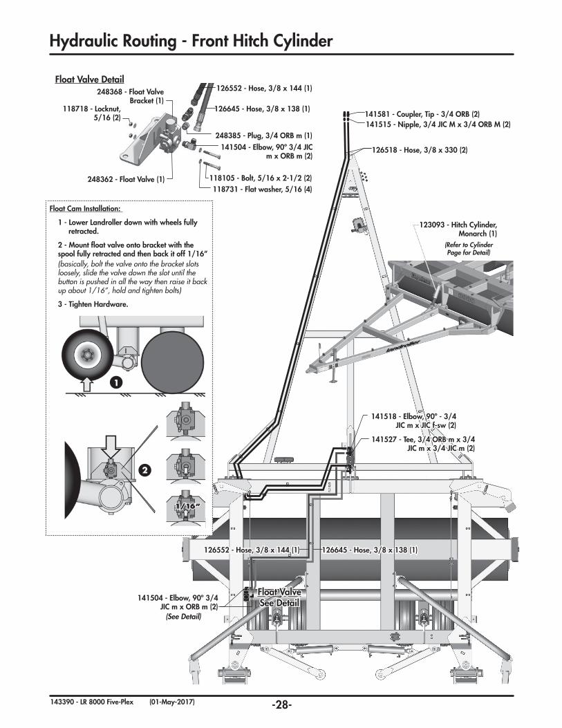
141515 - Nipple, 3/4 JIC M x 3/4 ORB M (2) 141581 - Coupler, Tip - 3/4 ORB (2)
126518 - Hose, 3/8 x 330 (2)
126645 - Hose, 3/8 x 138 (1)
141504 - Elbow, 90º 3/4 JIC m x ORB m (2)
126552 - Hose, 3/8 x 144 (1)
141518 - Elbow, 90º - 3/4 JIC m x JIC f-sw (2)
141527 - Tee, 3/4 ORB m x 3/4 JIC m x 3/4 JIC m (2)
(See Detail)
141504 - Elbow, 90º 3/4 JIC m x ORB m (2)
248385 - Plug, 3/4 ORB m (1)
Float Valve Detail
118105 - Bolt, 5/16 x 2-1/2 (2)118731 - Flat washer, 5/16 (4)
248362 - Float Valve (1)
118718 - Locknut, 5/16 (2)
248368 - Float Valve Bracket (1)
126645 - Hose, 3/8 x 138 (1)
126552 - Hose, 3/8 x 144 (1)
Float Valve See Detail
Float Cam Installation:
1 - Lower Landroller down with wheels fully retracted.
2 - Mount float valve onto bracket with the spool fully retracted and then back it off 1/16”(basically, bolt the valve onto the bracket slots loosely, slide the valve down the slot until the button is pushed in all the way then raise it back up about 1/16”, hold and tighten bolts)
3 - Tighten Hardware.
1
2
(Refer to Cylinder Page for Detail)
123093 - Hitch Cylinder, Monarch (1)
Hydraulic Routing - Front Hitch Cylinder
-29-143390 - LR 8000 Five-Plex (01-May-2017)
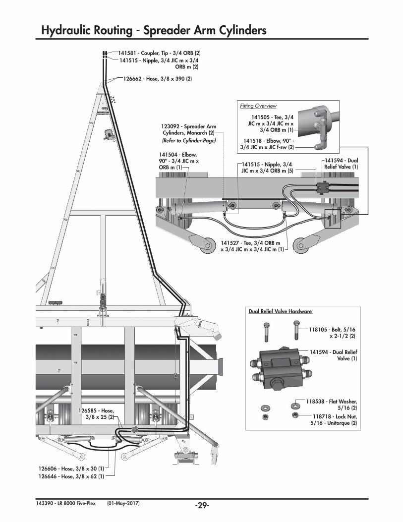
141515 - Nipple, 3/4 JIC m x 3/4 ORB m (2)
141581 - Coupler, Tip - 3/4 ORB (2)
126662 - Hose, 3/8 x 390 (2)
126606 - Hose, 3/8 x 30 (1) 126646 - Hose, 3/8 x 62 (1)
126585 - Hose, 3/8 x 25 (2)
141594 - Dual Relief Valve (1)
118718 - Lock Nut, 5/16 - Unitorque (2)
118538 - Flat Washer, 5/16 (2)
118105 - Bolt, 5/16 x 2-1/2 (2)
Dual Relief Valve Hardware
141515 - Nipple, 3/4 JIC m x 3/4 ORB m (5)
141504 - Elbow, 90º - 3/4 JIC m x ORB m (1)
141594 - Dual Relief Valve (1)
(Refer to Cylinder Page)
123092 - Spreader Arm Cylinders, Monarch (2)
141527 - Tee, 3/4 ORB m x 3/4 JIC m x 3/4 JIC m (1)
141505 - Tee, 3/4 JIC m x 3/4 JIC m x
3/4 ORB m (1)
141518 - Elbow, 90º - 3/4 JIC m x JIC f-sw (2)
Fitting Overview
Hydraulic Routing - Spreader Arm Cylinders
-30-143390 - LR 8000 Five-Plex (01-May-2017)
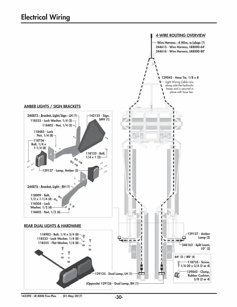
AMBER LIGHTS / SIGN BRACKETS
REAR DUAL LIGHTS & HARDWARE
246163 - Split Loom, 10” (2)
Wire Harness - 4 Wire, w/plugs (1)
244616 - Wire Harness, LR8000-80’244615 - Wire Harness, LR8000-64’
129125 - Dual Lamp, LH (1)
Light Wiring Cable runs along side the hydraulic hoses and is secured in
place with hose ties.
129045 - Hose Tie, 1/8 x 8
129127 - Amber Lamp (2)
129042 - Clamp, Rubber Cushion,
3/8 (2 or 4)
118735 - Screw,1/4-20 x 3/4 (2 or 4)
64’ (2) / 80’ (4)
129126 - Dual Lamp, RH (1)(Opposite)
142135 - Sign, SMV (1)118533 - Lock Washer, 1/4 (2)
118402 - Nut, 1/4 (2)
118504 - Lock Washer, 1/2 (4)118405 - Nut, 1/2 (4)
118483 - Lock Nut, 1/4 (8)
118756 - Bolt, 1/4 x
1-1/4 (8)
118009 - Bolt, 1/2 x 1-1/4 (4)
118123 - Bolt, 1/4 x 1 (2)
244875 - Bracket, Light/Sign - LH (1)
244876 - Bracket, Light - RH (1)
129127 - Lamp, Amber (2)
118533 - Lock Washer, 1/4 (8)118983 - Bolt, 1/4 x 3/4 (8)
118555 - Flat Washer, 1/4 (8)
4-WIRE ROUTING OVERVIEW
Electrical Wiring
-31-143390 - LR 8000 Five-Plex (01-May-2017)
2 YearLimited Warranty - Agricultural Products
Degelman Industries Ltd. (“Degelman”) warrants to the original purchaser of any new Degelman equipment, purchased from an authorized Degelman dealer, that the equipment will be free from defects in material and workmanship for a period of two (2) years from the date of delivery, for non-commercial use (including farm, institutional, government, and municipality) and (1) year from the date of delivery for commercial use. The obligation of Degelman to the purchaser under this warranty is limited to the repair or replacement of defective parts in the first year and to the provision, but not the installation of replacement parts in the second year. Degelman reserves the right to inspect any equipment or parts which are claimed to have been defective in material or workmanship.
This warranty limits its replacement or repair coverage to what is consistent with the warranty of Degelman’s suppliers of purchased components.
Replacement or repair parts installed in the equipment covered by this limited warranty are warranted for ninety (90) days from the date of delivery of such part or the expiration of the applicable new equipment warranty period, which ever occurs later. Warranted parts shall be provided at no cost to the user at an authorized Degelman dealer during regular working hours. Warranted replacement parts will either be replaced or rebuilt at Degelman’s discretion.
Disclaimer of implied warranties & consequential damages
This warranty shall not be interpreted to render Degelman Industries Ltd. liable for injury, death, property damage or damages of any kind, whether direct, consequential, or contingent to property. Without limiting the generality of the foregoing, Degelman shall not be liable for damages resulting from any cause beyond its reasonable control, including, without limitation, loss of crops, any expense or loss of labour, supplies, rental machinery or loss of use.
No other warranty of any kind whatsoever, express or implied is made with respect to this sale; and all implied warranties of merchantability and fitness for a particular purpose which exceed the obligations set forth in this written warranty are hereby disclaimed and excluded from this sale. This exclusion shall not apply in any jurisdiction where it is not permitted by law.
This limited warranty shall not apply:
1. If, in the sole opinion of Degelman, the unit has been subjected to misapplication, abuse, misuse, negligence accident or incorrect off-site machine set-up.
2. To any goods that have sustained damage or deterioration attributable to a lack of routine maintenance (eg. Check and Re-torque of fastening hardware, Hydraulic fluid purities, drive train alignments, and clutch operation)
3. If parts not made or supplied by Degelman have been used in the connection with the unit, if, in the sole judgement of Degelman such use affects its performance, safety, stability or reliability.
4. If the unit has been altered or repaired outside of an authorized Degelman dealership in a manner which, in the sole judgement of Degelman, affects its performance, safety, stability or reliability.
5. To expendable or wear items such as (eg. Harrow tines, Rock Picker and Rock Rake wear teeth and replaceable bushings and pins.) and any other items that in the company’s sole judgement are a wear item.
No employee or representative of Degelman Industries Ltd. is authorized to change this limited warranty in any way or grant any other warranty unless such change is made in writing and signed by the Degelman Service Manager.
This limited warranty is subject to any future availability of supply, which may directly affect Degelman’s ability to obtain materials or manufacture replacement parts.
Degelman reserves the right to make improvements in design or changes in specifications at any time, without incurring obligations to owners of equipment previously delivered.
This limited warranty is subject to compliance by the customer to the enclosed Retail Customer’s Responsibility Under Degelman Warranty.
Warranty
-32-143390 - LR 8000 Five-Plex (01-May-2017)
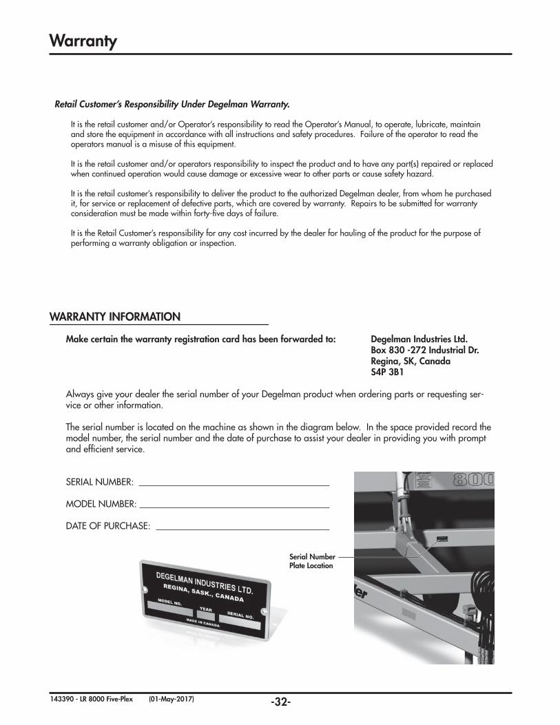
Serial Number Plate Location
Warranty
Make certain the warranty registration card has been forwarded to: Degelman Industries Ltd. Box 830 -272 Industrial Dr. Regina, SK, Canada S4P 3B1
Always give your dealer the serial number of your Degelman product when ordering parts or requesting ser-vice or other information.
The serial number is located on the machine as shown in the diagram below. In the space provided record the model number, the serial number and the date of purchase to assist your dealer in providing you with prompt and efficient service.
SERIAL NUMBER:
MODEL NUMBER:
DATE OF PURCHASE:
WARRANTY INFORMATION
Retail Customer’s Responsibility Under Degelman Warranty.
It is the retail customer and/or Operator’s responsibility to read the Operator’s Manual, to operate, lubricate, maintain and store the equipment in accordance with all instructions and safety procedures. Failure of the operator to read the operators manual is a misuse of this equipment.
It is the retail customer and/or operators responsibility to inspect the product and to have any part(s) repaired or replaced when continued operation would cause damage or excessive wear to other parts or cause safety hazard.
It is the retail customer’s responsibility to deliver the product to the authorized Degelman dealer, from whom he purchased it, for service or replacement of defective parts, which are covered by warranty. Repairs to be submitted for warranty consideration must be made within forty-five days of failure.
It is the Retail Customer’s responsibility for any cost incurred by the dealer for hauling of the product for the purpose of performing a warranty obligation or inspection.