operator workstation technical bulletin - johnson controls
TRANSCRIPT

Technical Bulletin
Issue Date June 18, 2004
© 2004 Johnson Controls, Inc. www.johnsoncontrols.com Code No. LIT-636013 Metasys Release 12.04
Operator Workstation
Operator Workstation............................................................................3
Introduction......................................................................................................... 3
Key Concepts...................................................................................................... 5
Operator Workstation ........................................................................................................ 5 Theory of Operation .......................................................................................................... 5 Multiple Direct Connects ................................................................................................... 7 Fire OWS ........................................................................................................................ 10 Components.................................................................................................................... 10 Design Considerations: Configured or Non-configured Workstation............................... 12 Design Considerations: Direct or Dial-up Workstation .................................................... 15 OWS Installation ............................................................................................................. 16 Configure a Printer for the Metasys N1 System.............................................................. 23 Configure the OWS for Printers ...................................................................................... 25 Example of Five OWSs All Running on the Same Operating System and Three Printers .................................................................................................................26 Mixed Operating Systems ............................................................................................... 29 Print Change-of-State (COS) Reports............................................................................. 29 Print Reports and Summaries in Color............................................................................ 29 General Modem Configuration ........................................................................................ 32 Modem Wiring ................................................................................................................. 33 Commissioning Overview................................................................................................ 35 Hardware Commissioning ............................................................................................... 36 Commissioning PMI New Project Software..................................................................... 37 Commissioning PMI Software: Upgrading Existing Jobs ................................................ 40
Detailed Procedures......................................................................................... 42
Commissioning a New OWS........................................................................................... 42 Installing Software........................................................................................................... 42 Installing Metasys Person-Machine Interface (PMI) Software......................................... 42

Operator Workstation Technical Bulletin 2
Installing Metasys PMI Upgrade Software ...................................................................... 43 Establishing a Connection to an N1 Network for the First Time with a Non-configured Workstation ..................................................................................................................... 44 Direct Connecting to N1 LAN - Ethernet Network ........................................................... 44 Direct Connecting to a Network Control Module (NCM) ................................................. 45 Dial-up Connecting to an NCM - with Modem................................................................. 45 Dial-up Connecting to an NCM - with Integrated Services Digital Network (ISDN)......... 46 Adding a Printer Supported by the Windows 2000 Professional Operating System....... 46 Adding an IBM Proprinter Printer for NCM Printing......................................................... 47 Configuring the OWS for Printers.................................................................................... 47 Fixing Line Feed Problems when Using a Serial Printer ................................................. 50 Connecting and Configuring a Modem to an OWS ......................................................... 54 Connecting and Configuring a Modem to an NCM ......................................................... 56 Adding User-Defined Modems ........................................................................................ 56 Configuring ISDN Modems ............................................................................................. 57 Installing the Microsoft Backup Utility.............................................................................. 59 Installing Metasys PMI New Project Software................................................................. 61 Installing Metasys PMI Upgrade Software ...................................................................... 63 Disabling the Parallel Port Check.................................................................................... 66
Troubleshooting ............................................................................................... 67
Global Alarm Indicator Reset .......................................................................................... 67 Metasys N1 Ethernet Communication Problems After Any Metasys PMI Software Upgrade .......................................................................................................................... 69 Windows 2000 Operating Systems ................................................................................. 69

Operator Workstation Technical Bulletin 3
Operator Workstation
Introduction The Operator Workstation (OWS) is an easy-to-use, high-level interface for the operator of a Metasys® Building Automation System (BAS). This document describes the OWS and how to:
• commission a new OWS
• install software
• install Metasys Person-Machine Interface (PMI) software
• install Metasys PMI upgrade software
• establish a connection to an N1 network for the first time with a non-configured workstation
• direct connect to N1 LAN - Ethernet Network
• direct connect to a Network Control Module (NCM)
• dial-up connect to an NCM - with modem
• dial-up connect to an NCM - with Integrated Services Digital Network (ISDN)
• add a printer supported by the Windows® 2000 Professional operating system
• add an Lexmark® Proprinter® printer for NCM printing
• configure the OWS for printers
• fix line feed problems when using a serial printer
• connect and configure a modem to an OWS
• connect and configure a modem to an NCM
• add user-defined modems
• configure ISDN Modems
• install the Microsoft® Backup Utility
• install Metasys PMI new project software

Operator Workstation Technical Bulletin 4
• install Metasys PMI upgrade software
• disable the parallel port check
Use this document with the Metasys Software Installation and Platform Requirements Technical Bulletin (LIT-12012), which contains hardware and software requirements and supported platforms.
This document may contain information about discontinued features or products. This information is for reference only. Beginning with Release 12.04, the following features or products are no longer supported:
• ARCNET® protocol
• Graphic Programming Language (GPL). Support for GPL ended at Release 12.03.
• Microsoft Windows 98 operating system
• Windows NT® operating system

Operator Workstation Technical Bulletin 5
Key Concepts Operator Workstation
The Operator Workstation (OWS) is an easy-to-use, high-level interface for the operator of a BAS consisting of one or more N1 networks. With the workstation, the operator:
• monitors the facility
• controls the facility
• examines historical and current information about facility operations
• defines objects and features
Theory of Operation The Metasys OWS hardware is a Personal Computer (PC) that consists of a system unit, color monitor, keyboard, mouse, and a Network Interface Card (NIC). A NIC, modem, and RS-232 allow the workstation to communicate with other nodes, such as other workstations and NCMs on the N1 Local Area Network (LAN).
The modem provides dial-up communication between the nodes from a remote location, and the RS-232 connection allows the workstation to communicate with an NCM directly.
The workstation runs several software packages that provide advanced BAS functions, including the Metasys PMI software, and Microsoft Windows operating system software. Optionally, the workstation may also have a printer.
For a list of supported platforms, refer to the Metasys Software Installation and Platform Requirements Technical Bulletin (LIT-12012).

Operator Workstation Technical Bulletin 6
Types The OWS can be one of five types, depending on how you connect the workstation to the Metasys N1 network and whether the workstation is configured. The workstation can connect directly to the N1 LAN, to the NCM, or remotely connect to the NCM over telephone lines. Also, the workstation can be a configured device capable of all Metasys Network operations or a non-configured device capable of a limited set of Metasys Network operations. Figure 1 summarizes the five OWS types.
N1 LAN
LAN Direct Connected1. Configured
NCM Dial-up Connected4. Configured, or5. Unconfigured
Modem(internal orexternal)
Modem
NCM Direct Connected2. Configured, or3. Unconfigured
N2 Bus
N2 BusN2 Bus
OWSCONF
For Integrated Services Digital Network (ISDN) applications, useterminal adapters in place of modems.
Note:
For multi-direct application, see Figure 2.
Note:
N2 Bus
Figure 1: OWS Configuration Options

Operator Workstation Technical Bulletin 7
Modes An OWS has two modes of operation: online and offline.
The online mode offers the operator the following functions:
• Basic Operator Control—Provides basic interaction with the BAS that consists of one or more N1 networks. The operator receives data, adjusts operating parameters, commands specific operations, reschedules events, and performs uploads and downloads.
• Automatic Data Output—Receives messages, warnings, alarms, and reports to a printer or a workstation display or file.
• Online Definition—Defines new objects, setup trends, totalizations, demand limiting, and other features.
• Dynamic Data Exchange—Provides the exchange of information between the Metasys Network and third-party Windows operating system applications with Metalink software. These applications can use Metasys system data from objects and attributes both historically (offline) and dynamically (online).
• PC Operation—Performs ordinary PC tasks and runs third-party software such as Microsoft Excel.
• NCSETUP for Windows operating system software—Configures the NCM.
• The offline mode offers the operator or application engineer the following functions:
- Data Definition Language (DDL) Definition—Defines hardware and software components of a Metasys Network.
- Graphic Programming Language (GPL) Definition—Defines software objects and creates control strategies for the NCM.
Multiple Direct Connects The OWS can connect to multiple NCMs by way of its serial communication (COM) ports. This application benefits jobs with remote NCMs and a central OWS, where leased or dedicated lines are preferred. Multiple direct connections are useful, because you now only need one workstation to connect to multiple NCMs.
If your remote NCMs are in different time zones, use the time zone for the network to which you made the last connection. If several networks are connected and you change the time-of-day at one network, then only that network has its time updated.
Figure 2 shows an example of a multiple direct-connect workstation.

Operator Workstation Technical Bulletin 8
N1 LAN
N2 Bus
N2 Bus
To other nodes
NCM
N1 LAN
Modem*
NCM
NCM
NCM NCM
NCM
Modem*
* Leased line modem at 9600 baud.MULTOWS
RS-232 Direct Connects
Figure 2: Multi-Direct OWS As shown in Figure 2, up to four NCMs can connect to COM ports of the OWS. The actual number of NCMs that can connect directly to the workstation’s COM ports depends on the type of PC. A group of NCMs on the N1 can connect from an NCM that is directly connected to the OWS.
Each directly connected NCM (or group of NCMs) is on a separate network, which means that each direct-connect network has an individual N1 global database. If you wish to have password access to all directly connected NCMs, you need to define your PMI password separately at each direct-connect network. You can log on to all directly connected N1 networks at the same time. (Use the Network Summary to switch between networks.) Each directly connected NCM can communicate directly with control modules installed next to it in the same NCM or with other NCMs on its remote N1 network.
Alarm messages can be broadcasted and acknowledged across N1 networks, even if the operator is not logged on the N1 network that is sending the message. For example, if you are logged on to Network A and a Change-of-State (COS) occurs at Network B, the report appears on the workstation. To act on this report, you do not need to log on to Network B, as long as you have password access to that network. The system performs the appropriate password checks internally.

Operator Workstation Technical Bulletin 9
Since each direct-connect N1 network has a separate global database, the direct-connect NCMs can share data between N1 or N2 devices on the same network. These NCMs cannot perform any of the tasks that are associated with Dynamic Data Access software (for example, obtaining the value of an object from a remote network). These types of tasks require the Metalink interface, a program included with the OWS software.
When the Facility Management System (FMS) Logon dialog box appears, a status window for each direct-connect network defined for this PC appears along the right side of the OWS screen (Figure 3). These direct-connect status windows show the:
• network name
• OWS COM port being used by the NCM
• status of the workstation
• communication speed of workstation to NCM connection
• workstation as configured or non-configured
Connected @ 9600 baudConfigured
NC Direct3
COM3
Connected @ 9600 baudConfigured
NC Direct2
COM2
Connected @ 9600 baudConfigured
NC Direct
COM1
NORTHBLD
WEST-BLD
EAST-BLD
OWSLOG
HDQTRSToronto
OKCancel
Enter Password:
Select network:
HDQTRS
FMS Logon
********
EAST-BLDHDQTRSNORTHBLDSOUTHBLDWEST-BLD
Figure 3: Logon Dialog Box and Direct-Connect Status Windows Direct-connect status windows can be minimized, in which case, they appear in the task bar at the bottom of the screen.

Operator Workstation Technical Bulletin 10
After you select an N1 network and enter your password, the Network Map appears for the chosen network. The direct-connect boxes remain displayed. They move to the background when you perform a task, such as displaying a summary.
A COS report from any directly connected NCM appears on the screen, even when no one is currently logged on. If your password allows, you may acknowledge the report without logging on; however, if you do not have password access, you can only acknowledge that you have read the report by selecting Look Later.
Editing DDL File for Multi-Direct Workstation After you have installed the OWS and the PMI software, the last step for configuring an OWS that supports multiple NCM direct connections is to edit the workstation’s Network/Port Configuration DDL file (@NET file). Specifically, add the PORT and NET statements for each multiple N1 network. Be sure to follow proper DDL syntax. Refer to the DDL Programmer’s Manual for instructions and a file example.
Fire OWS The Fire OWS is an Underwriters Laboratories Inc.® (UL) Listed OWS used for fire alarm reporting as part of the Metasys Intelligent Fire Network. Refer to the Fire Operator Workstation (Fire OWS) Technical Bulletin (LIT-636014) for more information.
Components The OWS consists of hardware and software components recommended for the Metasys N1 network. For a list of supported vendor configurations, refer to the Metasys Software Installation and Platform Requirements Technical Bulletin (LIT-12012).
Hardware Components The OWS consists of the following hardware components:
• Computer—Includes a system unit, monitor with display stand, keyboard, and mouse. The hard disk must have an absolute minimum of 500 Megabytes (MB) for loading the system (Windows operating system software, PMI, Graphic Programming Language [GPL], and a small database).
• Disk Drive—One 1.44 MB 3.5-inch floppy drive is required for loading (quick patches only) and backup purposes.
• CD-ROM Drive—A CD-ROM drive (4x or higher) is required for installing Metasys software.

Operator Workstation Technical Bulletin 11
• NIC—Card that is installed into the OWS and used to make the physical connection to the network. The type of card depends on whether you connect to an ARCNET or Ethernet network. In both cases, you must install and connect an NIC or the OWS cannot communicate on either network.
Note: If you configure the NCM to use an Ethernet connection, always install the Ethernet NIC in the NCM to prevent download failures.
• Serial Communications Board (optional)—Computer board that provides extra serial ports required for connecting one workstation to multiple networks. The serial board needed depends on the model of your PC. Refer to the Metasys Software Installation and Platform Requirements Technical Bulletin (LIT-12012).
• Additional Random Access Memory (RAM)— A minimum total of 128 MB of memory is required for Windows 2000 Professional operating system software and Windows XP Professional operating system software.
• Printer (optional)—An output device for printing Metasys system summaries and reports in black or color.
• Sound Blaster® Compatible Sound Board—Adds audio/tone sound to Metasys system operations for Change-of-State reporting to help differentiate among alarm levels and enable the use of multimedia technology. For Windows 2000 Professional operating system and Windows XP Professional operating system software, a soundboard is required. The operating systems do not provide support for the PC speaker.
• Modems (optional)—Enable dial-up or leased line connections between the OWS and the NCM. One modem is required at an NCM and another one is required at the workstation.
• An Integrated Services Digital Network (ISDN) application uses higher speed modems (optional). An ISDN modem is required at the NCM and another at the workstation.
The modems supported for use with Metasys software are listed in the Computer Price List (pcprices.doc) at The Advisor > Business Focus > Purchasing > ePurchasing > CG Computer Purchasing. These modems have been thoroughly tested. The baud rates of these modems vary, and the maximum baud rate used on the OWS depends on the dial-up NCM.

Operator Workstation Technical Bulletin 12
Refer to the Network Control Module 300 Series Technical Bulletin (LIT-6360251) for specific maximum baud rates.
The supported ISDN modem is the ADTRAN ISU Express. An RS-232 cable is used to connect the external modems to the OWS or NCM.
Software Components The OWS consists of the following software components:
• Metasys PMI Software—Programs that provide all operator Metasys system functions, including DDL and Metasys Metalink software. Metalink software is an interface package for the OWS that allows data sharing between the Metasys Network and third-party Windows operating system software packages that are Dynamic Data Exchange (DDE) compatible.
• Metasys system GPL (optional)—Graphics-oriented programming language for creating software objects and programming control strategies.
• Metasys system GPL Heating, Ventilating, and Air Conditioning (HVAC) Library (optional)—Set of tested GPL compounds that the application engineer can use to program common BAS applications.
• Metasys system JC-BASIC Programming Language (optional)—Textual programming language for creating processes.
• Third-party Software—Several software packages provided by third-party software manufacturers. For a current list of recommended third-party software packages, refer to the Metasys Software Installation and Platform Requirements Technical Bulletin (LIT-12012).
Design Considerations: Configured or Non-Configured Workstation Decide whether you want to set up the OWS as a configured or non-configured workstation. A configured workstation, either direct or dial-up connected, is a defined device in the Metasys system N1 database and has the full set of communication functions with other nodes. All other nodes on the N1 network can identify a configured workstation. A non-configured workstation is not defined as a hardware object in the Metasys system database and has a limited set of communication functions with other nodes. Unlike the configured workstation, any other node on the N1 network cannot identify a non-configured workstation. Therefore, a non-configured workstation does not automatically receive reports from other nodes.
Table 1 lists the different capabilities of the configured and non-configured OWS.

Operator Workstation Technical Bulletin 13
Table 1: Capabilities of OWS Capability Description Purpose Configured Non-
configured Online
Online Database Generation
Workstation allows you to: • define new objects • modify setup for existing
objects • implement feature actions
Provides central operator definition of Metasys N1 system operations.
Yes Yes
Commands Workstation allows you to: • start, stop, or reset operations • communications • change operational setpoints
Provides central user override control of all Metasys N1 system operations. Also useful for system test.
Yes Yes
Monitor Facility Workstation provides: • pop-up message windows to
alert user to special situations
• summaries automatically sent at particular time or event
Keeps operator current on status of facility.
Yes No
Maintenance Provides maintenance flags to the operator based on hours of usage, number of cycles, and so on.
Optimizes maintenance efforts.
Yes No
DDE Interface (Metalink Software)
Provides data exchange between the Metasys N1 network and third-party Windows operating system applications.
Provides useful reports, spreadsheets, and work orders.
Yes Yes
Store Historical Data
Uploads and stores historical data on system performance automatically.
Provides convenient record keeping, and establishes database accessible to third-party programs.
Yes No
Graphics Allows both graphic and textual data presentation.
Provides faster user recognition.
Yes Yes
Windows Display is divided into regions that can be sized and moved, and act as separate displays.
Provides access to several types of information simultaneously.
Yes Yes
System Archive Stores operating programs and parameter as backup.
Provides quick, easy recovery after power loss or system repair.
Yes Yes
Continued on next page . . .

Operator Workstation Technical Bulletin 14
Capability (Cont.)
Description Purpose Configured Non-configured
Offline Password Protection
Allows definition of different levels of system access for various users as defined by their password. See the Non-configured Workstation Security section.
Limits exposure to errors or tampering by unqualified users.
Yes Yes
NCSETUP for Windows Operating System Software
Allows you to set up, modify, and configure NCMs for the Metasys Network.
Configures NCM for use on Metasys Network.
Yes Yes
GPL Enables operator to program Metasys software functions by positioning and joining graphic symbols.
Simplifies custom programming
No No
DDL Enables operator to define PC groups, systems, and objects using lines of text.
Provides a quick method for defining large blocks of new system/objects.
Yes Yes
Archive Allows archiving of trend, totalization, follow-up, and status reports.
Provides a method of storing data.
Yes No
Non-configured Workstation Security Carefully consider your security needs when a person with a non-configured workstation has access to an N1 network. A non-configured direct or dial-up connection allows any person who has knowledge of the Metasys N1 network’s name and default Level 1 password to view and edit the password database. This may lead to a security risk.
Non-configured workstations do not have a PC name in the NET.ddl file. See the following NET.ddl file example and note that the NET Keyword string (located in the third line) contains no PC name, thus preventing PC identification on a network.
@NET PORT "LPT1", 3 NET "XYZ-BLDG", "XYZ-BLDG NETWORK", NCDIAL "T", "123-4567"
The default password, METASYS, is created when the NET.ddl file is compiled. If a workstation has never been connected to an N1 network, only the default password exists.

Operator Workstation Technical Bulletin 15
To prevent access to the Metasys N1 network from a non-configured workstation, delete the Metasys system default password from the PMI software. Refer to the Defining Passwords (LIT-120150) chapter of the Operator Workstation User’s Manual. Once the Metasys system default password is removed, you cannot use non-configured access because a non-configured workstation does not know any other password. Use a configured workstation for dial-up capabilities.
Design Considerations: Direct or Dial-Up Workstation Consider how to connect the OWS: direct or dial-up connection. A directly connected workstation connects to the N1 LAN or to an NCM via an RS-232 cable. A dial-up workstation connects to a modem, which allows access to the Metasys N1 network over telephone lines. The primary difference between direct and dial-up connections is communication speed. See Table 2.
Table 2: Design Considerations Type of Connection Maximum Communication Speed
N1 LAN 10 Million bits per second (Mbps) Ethernet network 2.5 Mbps ARCNET network
Direct
NCM100/200 NCM300 Series
1200 to 19,200 baud* 1200 to 57,600 baud
Dial-Up NCM100/200 NCM300 Series
1200 to 9600 baud 1200 to 38,400 baud* 57,600 for ISDN
*Notes: A direct-connect default destination does not work, but a direct-connect OWS can be a default destination. For the NCM300 Series only: Above the 19,200 baud, use a 16-character First In, First Out (FIFO) serial card. The serial card must use a 16550AF UART or equivalent. An example of a 16550AF serial card is the BOCA I/O AT55.
When selecting the connection types, be sure to follow these rules:
• Direct connections can use COM1, COM2, COM3, and COM4, depending on PC type.
• Dial-up connections can use COM1 and COM2 only; they cannot use COM3 or COM4.
• An expansion board may be required for additional COM in multiple direct connection applications. Refer to the Metasys Software Installation and Platform Requirements Technical Bulletin (LIT-12012) for recommendations for your PC.
• The maximum length allowed for the RS-232 is 50 feet (EIA-232-D). If the NCM must be placed in a remote location, use an alternate communication scheme such as dedicated line modems.

Operator Workstation Technical Bulletin 16
OWS Installation Physical Dimensions The following specifications for physical dimensions and power vary with the specific platform. See the manufacturer’s literature for details.
Table 3 describes typical physical dimensions of the OWS components.
Table 3: Typical Physical Dimensions for the Computer Configured as OWS Typical Area Required (Approximate)
Type of Chassis
System Unit Height x Width x Depth
Monitor Height x Width x Depth
Keyboard Height x Width x Depth
Desktop 152 mm x 406 mm x 419 mm (6 in. x 16 in. x 16.5 in.)
381 mm x 356 mm x 406 mm(15 in. x 14 in. x 16 in.)
51 x 495 x 216 mm (2 in. x 19.5 in. x 8.5 in.)
Floor Standing
597 mm x 165 mm x 483 mm (23.5 in. x 6.5 in. x 19 in.)
362 mm x 356 mm x 381 mm(14.25 in. x 14 in. x 15 in.)
51 mm x 495 mm x 216 mm (2 in. x 19.5 in. x 8.5 in.)
Portable 114 mm x 216 mm x 343 mm (4.5 in. x 8.5 in. x 13.5 in.)
N/A N/A
16.5 mm x 343 mm x 165 mm(0.65 in. x 13.5 in. x 6.5 in.)
Table 4 describes typical physical dimensions of the OWS accessories.
Table 4: Physical Dimensions of OWS Accessories Accessory Typical Area Required (Approximate) Height x Width x Depth Printer 127 mm x 419 mm x 356 mm (5 in. x 16.5 in. x 14 in.) Multi Tech® MultiModemII™ Modem
35 mm x 156 mm x 229 mm (1.4 in. x 6.2 in. x 9.0 in.)
ADTRAN ISU Express 41 mm x 165 mm x 210 mm (1.6 in. x 6.5 in. x 8.25 in.) Fiber-Optic Transceiver 25 mm x 69 mm x 43 mm (1.0 in. x 2.7 in. x 1.7 in.) Mouse (and Pad) 203 mm x 229 mm (8.0 in. x 9.0 in.)

Operator Workstation Technical Bulletin 17
Power Requirements Table 5 describes the typical power requirements for major OWS components.
Table 5: Typical Power Requirements Component Power Requirements Desktop Computer 100 VAC-125 VAC at 2.5 A-3.2 A, 50/60 Hz
(200 VAC-240 VAC at 1.3 A-2.0 A, 50/60 Hz) Floor Standing Computer 100 VAC-125 VAC at 5.3 A, 50/60 Hz
(200 VAC-240 VAC at 2.7 A, 50/60 Hz) Portable Computer 120 VAC at 1.0 A, 50/60 Hz
(220 VAC-240 VAC, 50/60 Hz) Printer 120 VAC at 1.0 A, 60 Hz Multi Tech MultiModemII Modem
115 VAC at 0.3 A, 60 Hz
ADTRAN ISU Express 115 VAC, 60 Hz, 6.5 Watt Maximum Dissipation without Plain Old Telephone Service (POTS) or Modem Options 220 VAC, 50 Hz, 13 Watt Maximum Dissipation with POTS and Modem Options
Environmental Information The following specifications for ambient operating temperature and humidity vary with the specific platform. See the manufacturer’s literature for details.
The OWS is rated for use in light industrial or office room applications, specified as follows:
• ambient operating temperature: 10 to 40°C (50 to 104°F)
• ambient operating humidity: 20 to 80%
• The atmosphere must be free of corrosive chemical vapors that may damage electronic equipment.

Operator Workstation Technical Bulletin 18
Wiring—Sequence of Steps The wiring procedure depends on whether the OWS is directly connected to the N1 LAN, directly connected to an NCM, or dial-up connected to an NCM. (The following instructions presume all boards are installed and properly configured.) Table 6 provides a summary of OWS connections.
Table 6: OWS Connections Type of Connection Parallel
Port Serial Port (COM1)
Network Interface Card Ports
Additional Serial Ports (COM2 - COM4)
N1 LAN Printer* Not Used N1 LAN Not Used Direct Connect NCM Printer* NCM N/A Up to 3 NCMs Dial-Up Connect
NCM Printer* Modem N/A 1 Modem (COM2 only)
* Printer may be connected to a serial port.
opwstsPrinter
NCM NCM
Operator Workstation
T
T
T = 93 ohm Terminator CapNote:
Parallel
If the workstation is at the end of line, install 93 ohmterminator cap on open end of T-connector.
Figure 4: Directly Connecting OWS to N1 LAN

Operator Workstation Technical Bulletin 19
RESET
Printer
Operator Workstationor
NCM (door open)
to RS-232 Submodule
to RS-232 Serial Port
opwstsb
Parallelto Serial PortNote that the cable used to
connect to the NCM Serial Portis the same cable used tonotconnect to the NCM submodule.
Figure 5: Directly Connecting OWS to NCM101
Printer
Operator Workstationor
NCM200 (door open)
to RS-232 Submodule
to RS-232 Serial Port
opwst200
Parallelto Serial PortRESET
Note that the cable used toconnect to the NCM Serial Port
is the same cable used tonotconnect to the NCM submodule.
Figure 6: Directly Connecting OWS to NCM200

Operator Workstation Technical Bulletin 20
After making the physical connection and turning on the workstation, the initialization and connection process begins. A message window appears on the workstation screen displaying the status of the connection. Do not close this message window (by double-clicking the Control menu box), unless you want to cancel the connection. Closing the window cancels the connection.
During the connection process, the message changes to display the current connection status. If the connection fails, the message explains why. The explanation remains on the screen for 5 seconds before the Metasys PMI software begins in offline mode. (In offline mode, data from the NCM is unavailable.) To retry the connection, correct the reason for the failure and reboot the workstation.
Table 7 lists and explains the status and failure messages that can occur in the message window.
When directly connecting an OWS to an NCM, follow these guidelines:
• The OWS PC port must be set to the same baud rate as the NCM port.
• The OWS must have the network to which it is connecting defined in its database.
• If you are downloading from the direct-connect workstation to the NCM, the archive node address for the NCM must be the same as the NCM node address. If it is not, the download does not occur. For more information on specifying the archive node address, refer to the NCM setup information in the NCSETUP for Windows Technical Bulletin (LIT-6360251d).
• If you are downloading from the direct-connect workstation to the NCM, wait 2 to 3 minutes for the download to start before assuming failure.

Operator Workstation Technical Bulletin 21
Table 7: Messages that Can Occur during Direct Connection Message Explanation Code Downloading Metasys PMI code is being downloaded from the
workstation into the NCM. Connected @ XXXX Baud Configured The actual baud rate of connection is displayed in message. XXXX may vary depending on the rate and quality of the connection and can be significantly less than the selected baud.
The workstation and NCM are successfully connected at the specified baud rate. The workstation is configured.
Connected @ XXXX Baud Unconfigured The actual baud rate of connection is displayed in message. XXXX may vary depending on the rate and quality of the connection and can be significantly less than the selected baud.
The workstation and NCM are successfully connected at the specified baud rate. The workstation is not configured.
Connecting to NC . . . Physical connection and initialization of workstation is successful. Connection is occurring.
Data Downloading Data is being downloaded from the workstation into the NCM.
Disconnected, Failed! Cannot Read NC NOVRAM The workstation cannot read the network name from the NCM’s NOVRAM.
Disconnected, Failed! Cannot Read NC State Every 30 seconds the workstation attempts to read the state of the NCM. This message indicates the state cannot be read and the workstation has lost communication from the NCM.
Disconnected, Failed! Global Data Failed The process of synchronizing global data has failed. Disconnected, Failed! Memory Error An OWS memory error has occurred. Need system
reboot. Disconnected, Failed! Network Name Invalid The network name read from the NCM’s NOVRAM is
not defined in the workstation’s network database. Disconnected, Failed! No Communication NCM initialization failed or the workstation has
become physically disconnected from the NCM. Disconnected, Failed! Port Not Enabled OWS port initialization failed (hardware failure). Disconnected, Retrying Configured Connection between workstation and NCM is lost
because the NCM is rebooted or the cable is unplugged. Workstation is retrying connection. This message also occurs immediately before a code or data download.
Global Data Updating Global data is synchronizing between NCM and workstation.
Initializing . . . The initialization process is occurring. (The workstation must be initialized before the connection process can begin.)
NC Must Force Download NCM must be reset by using the reset button on the front, by manual command, or by cycling power on the NCM.
NC Needs a Download The NCM needs a download from the workstation. NC Not Defined NCM is not defined. Need to define the NCM in the
global database source file. See the Source File Development section (LIT-630020) of the DDL Programmer’s Manual for instructions.

Operator Workstation Technical Bulletin 22
Dial-Up Connections Figure 7 shows how baud rates can differ between the OWS to the modem, the NCM and the modem, and between the two modems.
modem
M E T A S Y S
The baud rate between the OWS and its modem is set in the PC configuration box. The fullrange of baud rates are valid for all four COM ports (1200 through 57,600).
The baud rate between the modems dependson the capability of the modems. The highestbaud supported should be used. It does not have to match the baud rate between the PC and its modem or between the NCM and its modem. The actualrate can be significantly less than the selected rate.
The baud rate between the NCM and its modem is set in the PC definition window in Metasyssoftware or in the NOVRAM View and Modify dialogbox (for download) in NCSETUP for Windows software. The range of valid baud rates depends on the NCM port in which the modem is connected. The highest baud rate to the modem should be used, even if it is not supported by the modem.
Figure 7: Modem to Device vs. Modem to Modem Connections The baud rate of connection is the actual rate of communication established between the OWS and the NCM. It is typically the modem baud rate but may be less depending on the quality of the phone line. The rate may change each time a connection is established.
OPWREM
RESET
Printer
Operator Workstation
MDM101
Modem
Note:
Serial
Telephone Line
Parallel
You can use an externalmodem connected to anRS-232 submodule insteadof an internal modem.
RS-232 Line
Figure 8: Remote Connection between OWS and NCM

Operator Workstation Technical Bulletin 23
NCM200
opwisdnPrinter
Operator Workstation
Parallel
ISDNModem
RESET
NCM to ISDN modemcable shown connects to NCM Port 2.
ISDN Line
ISDNModem
Serial
Figure 9: ISDN Remote Connection between OWS and NCM
Configure a Printer for the Metasys N1 System You can configure printers that have Windows operating system drivers, including many laser printers, to print Metasys N1 reports and messages. Configure color printers to print various color reports and the Critical summary. For details on color printing, see the Print Reports and Summaries in Color section of this technical bulletin.
Consider the complete system before installing any printers. There are two configuration possibilities:
• Single Operating System (OS)
- One or more OWSs, all using a single OS, with one or more printers connected to one or more of the OWSs. (A single OWS with a single printer falls into this category.)
- A Single OS is the recommended configuration and is described in the Single Operating System section of this document.
• Mixed Operating Systems
- Multiple OWSs, using mixed OSs, with one or more printers connected to one or more of the OWSs.
- Configuration of mixed Operating Systems requires special care. Refer to the Operator Workstation Appendix Technical Bulletin (LIT-1201696) for more help.

Operator Workstation Technical Bulletin 24
Single Operating System Review the following instructions and the Adding a Printer Supported by the Windows 2000 Professional Operating System detailed procedure, and make the recommended changes to prevent printer problems when using Metasys PMI software with any Windows operating system.
To print properly in the system, complete the two following procedures:
• Install each printer using standard Windows operating system installation procedures.
• Configure Metasys software to work with each printer.
Configuring Printers Supported by Windows 2000 Professional Operating System Software Repeat the Adding a Windows Operating System Printer in Windows 2000 Professional Operating System Software procedure for every printer type installed on the Metasys N1 network. For example, if you have three different printers connected to three of your five OWSs, then you must install three printer drivers on every OWS, even on those that do not have printers connected. If you add a new printer later, then you must add the new printer driver to all five OWSs.
IMPORTANT: Always reboot the PC when you finish making changes to the Windows Printer configuration.
Summary On every OWS, you must install a Windows operating system printer for every printer on the system, even if there are printers with the same name (Figure 10). Later, rename these printers to match the Metasys system printer object name. Each name must be unique.

Operator Workstation Technical Bulletin 25
Figure 10: Typical Screen after Installing All Windows Printers for a Metasys N1 Network
Configure the OWS for Printers After installing the Windows supported printers on all Operator Workstations, you must configure the individual Metasys system printer objects. This procedure is independent of the OS. You must configure every printer on the network. Each OWS with a physical printer connected must undergo this configuration process. See the Configuring the OWS for Printers section in this document.

Operator Workstation Technical Bulletin 26
Example of Five OWSs All Running on the Same Operating System and Three Printers
Here is an example of multiple OWSs with all OWSs running on the same OS and three printers.
Situation:
You have five OWSs all running on Windows 2000 Professional operating system software. Assume the OWSs are named OWS-210 through OWS-214. You have three Hewlett-Packard® DeskJet® 870C printers: one connected to OWS-210, the second connected to OWS-211, and the third connected to OWS-213. A Lexmark Proprinter® III printer (formerly an IBM® Proprinter III printer) is connected to OWS-214. No printer is connected to OWS-212.
Following the preceding process, you have installed the following printers on OWS-214:
Local:
The default printer LP-214 (renamed from IBM Proprinter III printers) Generic Text Printer IBM Proprinters (renamed from IBM Proprinter printers)
Remote:
HP® DeskJet 870C HP DeskJet 870C (copy 2) HP DeskJet 870C (copy 3)
Rename the remote printers as follows:
HP DeskJet 870C becomes LP-210 HP DeskJet 870C (copy 2) becomes LP-211 HP DeskJet 870C (copy 3) becomes LP-213
Repeat this process for each OWS (Figure 11). Table 8 is a complete description of this example.

Operator Workstation Technical Bulletin 27
Figure 11: Typical Screen after Windows Printer Installation Complete
Table 8: Required Printer Naming Conventions for All OWS Running on the Same Operating System OWS and Printer Printer after Initial Windows
Operating System Installation at OWS and Metasys N1 System Configuration
Windows Operating System Printer Names after Renaming the Remote Printers
OWS-210 Windows 2000 Professional Operating System (OS) Local Printer: HP LaserJet® 870C
Local: LP-2101
Generic/Text Only IBM Proprinters2
Remote: HP DeskJet 870C (Copy 2) HP DeskJet 870C (Copy 3) IBM Proprinter III
Local: LP-210 Generic/Text Only IBM Proprinters Remote: LP-211 LP-213 LP-214
OWS-211 Windows 2000 Professional OS Local Printer: HP LaserJet 870C
Local: LP-2111
Generic/Text Only IBM Proprinters2
Remote: HP DeskJet 870C (Copy 2) HP DeskJet 870C (Copy 3) IBM Proprinter III
Local: LP-211 Generic/Text Only IBM Proprinters Remote: LP-210 LP-213 LP-214
Continued on next page . . . 1. This is the printer that has been installed and tested locally and directly connected to the OWS. 2. This is an IBM Proprinter renamed to IBM Proprinters.

Operator Workstation Technical Bulletin 28
OWS and Printer (Cont.)
Printer after Initial Windows Operating System Installation at OWS and Metasys N1 System Configuration
Windows Operating System Printer Names after Renaming the Remote Printers
OWS 212 Windows 2000 Professional OS Local Printer: None
Local: (None) Generic/Text Only IBM Proprinters2
Remote: HP DeskJet 870C HP DeskJet 870C (Copy 2) HP DeskJet 870C (Copy 3) IBM Proprinter III
Local: (None) Generic/Text Only IBM Proprinters Remote: LP-210 LP-211 LP-213 LP-214
OWS-213 Windows 2000 Professional OS Local Printer: HP DeskJet 870C
Local: LP-2131
Generic/Text Only IBM Proprinters2
Remote: HP DeskJet 870C (Copy 2) HP DeskJet 870C (Copy 3) IBM Proprinter III
Local: LP-213 Generic Text Only IBM Proprinters Remote: LP-210 LP-211 LP-214
OWS-214 Windows 2000 Professional OS Local Printer: IBM Proprinter III
Local: LP-2141
Generic/Text Only IBM Proprinters2
Remote: HP DeskJet 870C HP DeskJet 870C (Copy 2) HP DeskJet 870C (Copy 3)
Local: LP-214 Generic/Text Only IBM Proprinters Remote: LP-210 LP-211 LP-213
1. This is the printer that has been installed and tested locally and directly connected to the OWS. 2. This is an IBM Proprinter renamed to IBM Proprinters.

Operator Workstation Technical Bulletin 29
Mixed Operating Systems Although installing printers that work across Metasys OWSs running on a single OS is relatively straightforward, configuring printers across mixed OSs requires special care.
IMPORTANT: You must first ensure that every printer has a driver that has the same name for all operating systems.
To ensure the printer driver name is the same for all OSs:
1. Install the printer in the usual way on the OWS to which the printer is to be connected. Print a test page.
2. Move the same printer to another OWS with the alternate OS. Install the printer in the usual way and print another test page. The Windows OS printer driver names on each test print must match.
There is no guarantee that all printers work, even if the printer driver names are identical. You may see General Protection Violation errors or no printing at all.
Many printers emulate another printer. An emulated printer may use a common driver across OSs. Examine your printer manual to check printer emulation. Test the printer as described previously to ensure the driver names are the same.
When you have a common driver, the configuration is the same as described in the Configuring the OWS for Printers detailed procedure. You must print a focus window across every OWS once the printers are fully installed.
If you add another printer to a Metasys N1 network with OWSs running on multiple OSs, you must repeat the printer tests to ensure driver names match.
Print Change-of-State (COS) Reports You cannot use an OWS serial printer with Windows 2000 Professional operating system and Windows XP Professional operating system software for COS reports.
Print Reports and Summaries in Color Printers that support color and style (bold and italic) printing can be used with OWSs to provide consistent color and style options for printing COS reports, critical summary messages, and various data that appear in the Metasys system windows.
If you have a color printer connected to an OWS and you are viewing colored data on the screen (for example, a trend or totalization graph), you can print that data in color. It is not necessary to reconfigure the printer, use a specific printer, or set any parameters on the OWS.

Operator Workstation Technical Bulletin 30
Verify that you are using the correct printer driver when printing to a color printer.
Printing reports and summaries, however, requires using specific printers and/or making changes to the METASYS.INI file. You can print COS reports in a variety of colors and styles using either dot matrix printers that support ESC/P escape codes sequences or Windows printers without using escape code sequences. The COS Critical summaries can only be printed in red or black but support any type of color printer. To enable color printing in all cases requires making changes to the METASYS.INI file. See the Modify the METASYS.INI File section of this document.
NCMs do not support color printing.
When using a color printer on an OWS, keep in mind that:
• the OWS connected to the color printer must have the color parameters added in that OWSs METASYS.INI file
• if two or more printers are connected to a single OWS, both printers must operate identically, because both printers use the same METASYS.INI file parameters
• if a report is directed to an OWS printer, the destination OWS METASYS.INI parameters take effect
• if a critical summary is printed, the METASYS.INI file parameters on the originating OWS take effect
• if printing COS messages in color without using escape code sequences, the proper driver must be installed for the color printer
Print Reports in Color Dot matrix printers that can print in multiple colors usually have a four-color ribbon containing the following colors:
• cyan (blue)
• magenta
• yellow
• black
When mixed together, violet, orange, and green are additional options. With the number of colors available, you can specify that you want a particular report, for example a Critical Alarm 1, to print red. In addition, you can print in each style, bold or italic, with any of the colors.

Operator Workstation Technical Bulletin 31
Modify the METASYS.INI File Add the specific parameters to the METASYS.INI file for printing colors or special effects. Refer to the Initialization Parameters Technical Bulletin (LIT-636345) for detailed explanations of the defaults and examples of how to change the parameters.
To assign a specific color, bold style, or italic style, to a particular report type, add the following (each line specifies the particular report): RrPrintCritical1=xxxx
RrPrintCritical2=xxxx
RrPrintCritical3=xxxx
RrPrintCritical4=xxxx
RrPrintOperatorTransaction=xxxx
RrPrintFollowup=xxxx
RrPrintStatus=xxxx
RrPrintCardReader=xxxx
xxxx=is a four digit number that defines the desired color/feature.
In addition to the RRPrintCritical parameters above, you must add a group of escape codes to specify color and print style to the METASYS.INI file. Open the METAPRN.INI file and identify the block of parameters that correspond to your printer. Copy this block of parameters from METAPRN.INI file and paste into the METASYS.INI file under the section heading [METASYS]. When using Windows printers for color printing of COS messages, no escape codes are required. Refer to the Initialization Parameters Technical Bulletin (LIT-636345) for more information.
Print COS Summaries Unlike the COS reports that have a variety of color choices, COS summaries can be printed only in red or black. The capability to print in red operates independently from the report logging described in the previous section. Any printer that supports color and is installed in Windows operating system software with compatible Windows driver software can be used to print the COS summaries in red. To enable the red printing, add the following single parameter to the METASYS.INI file: CossumPrintColor=1
Refer to the Initialization Parameters Technical Bulletin (LIT-636345) for the parameter settings.

Operator Workstation Technical Bulletin 32
Modify COS Buffer The COS buffer stores COS reports for printing. Two methods of configuring the buffer are available: Buffer Size and Buffer Interval. The print Buffer Size parameter specifies the number of COS reports buffered before they are sent to the printer. The print Buffer Interval parameter specifies the number of minutes the Metasys system waits until the buffer is sent to the printer, regardless of the number of messages in the buffer. Refer to the Initialization Parameters Technical Bulletin (LIT-636345) for the parameter settings.
You may configure up to four printers on an OWS for use at one time. When the COS buffer is enabled, all printers on that OWS are buffered. Each OWS has its own buffer; however, the same initialization parameter is used for all.
General Modem Configuration For a list of qualified modems, refer to the Computer Price List (pcprices.doc) at The Advisor > Business Focus > Purchasing > ePurchasing > CG Computer Purchasing.
PMI Release 11.00 and later allows you to select a modem from a list. All supported modem strings are located in MODEM.INI. The new file is referenced for setting up either OWS or NCM modem applications. The MODEM.INI file includes all modems currently supported by PMI software. New modems can be added in the field as the need arises. The MODEM.INI file is located in the same directory as METASYS.INI. The MODEM.INI file is also available on The Advisor. Refer to the Initialization Parameters Technical Bulletin (LIT-636345).
Update the MODEM.INI Occasionally a new set of modems supported by the Metasys N1 network is available from The Advisor site. To update a particular customer, copy the entire MODEM.INI from The Advisor and replace the present MODEM.INI on the PMI Release 11.00 or later job site.
Any user-defined modems are lost during the updating process.

Operator Workstation Technical Bulletin 33
Modem Wiring See the Configuring ISDN Modems detailed procedure and refer to the following connections.
OWS to Modem The external modem connects to the OWSs serial port (COM1 or COM2) with an RS-232 cable. The pinouts for this cable depend on the type of PC. Use the pinouts for your system.
Several computers support the 25-pin COM port.
Out
Out
Out
Out
Out
Out
Out
In
In
In
In
In
In
In1
2
3
45
6
7
818
20
2
34
5
6
7
818
20
FGTD Black
RD Brown
RTS RedCTS Orange
DSR YellowSG Green
DCD Blue
DTR White
Unused Violet
Operator Workstation25-pin COM Port
(male)
Modem(male)
OWS-MOD
In
Shell
Note: If you are using the Multi Tech Modem V32L (discontinued), cut pin 18 at the modem end.
Figure 12: Cable between 25-Pin COM Port and Modem (Allied Part CON94-3870-10)

Operator Workstation Technical Bulletin 34
Most computers support the 9-pin COM port. Use a null modem cable or prepare the RS-232 cable as shown in Figure 13.
Operator Workstation9-pin COM Port
( female)
1
2
3
4
5
6
7
8
9
2
3
4
5
6
7
8
20
22
Shell
25-pinModem(male)
Out
In
In
In
In
Out
Out
Out
Out
In
InIn
Out
Out
COM
Out
In
PORT-MOD
FG Shell
Figure 13: Cable between 9-Pin COM Port and Modem (Allied Part CON94-3690-10)
NCM to ISDN Modem This section shows the cable for connecting the NCM (Port 2) to the ADTRAN ISU Express. Use a standard modem cable or prepare the cable as shown in Figure 14. For more information on NCM cables, refer to the Network Control Module 200 Series Technical Bulletin (LIT-636025) and the Network Control Module 300 Series Technical Bulletin (LIT-6360251).
2
3456
720
NCM(DTE)
DB25 (male)
NCM-TERM
ISDN Modem(DCE)
DB25 (male)
23
456
720
TDRDRTS
CTSDSRSG
DTR
InOutIn
OutOut
In
OutIn
Out
InIn
Out
Shell1FG
Figure 14: Cable between NCM200 Port 2 and ADTRAN ISU Express

Operator Workstation Technical Bulletin 35
Commissioning Overview The commissioning process depends on whether it is a new project or existing job.
If the OWS does not function properly after installation, refer to the Operator Workstation Appendix Technical Bulletin (LIT-1201696).
The information in this document is current as of its revision date. For updates, refer to the Readme.ows and Install.ows text files provided with the new release of the software.
Perform a PREP-FOR command before database restoration or conversion to set up environment variables. Refer to the Operator Workstation Appendix Technical Bulletin (LIT-1201696).
Commissioning a New Project See the Commissioning PMI New Project Software section in the Detailed Procedures section of this document for more information.
Commissioning an Existing Job Commissioning involves installing the new software release over the old software release if:
• this is an existing job
• the hardware configuration is correct
• the job does not use multiple direct connections
See the Commissioning Software: Upgrading Existing Jobs section.
However, if the job uses multiple direct connections, but additional serial boards are not already installed on your system, you need to install serial boards. In this case, see the Extra Serial Boards section in the Hardware Commissioning section. See the Commissioning Software: Upgrading Existing Jobs section to install the Metasys N1 system software.

Operator Workstation Technical Bulletin 36
Hardware Commissioning Commissioning hardware can involve the installation of the following equipment: memory, an NIC, extra serial boards, and a mouse. Specific procedures may depend on the model and brand of equipment being used.
Computer Platforms The hardware required for an OWS may include: added memory, an NIC, extra serial boards, and a mouse. Refer to the Metasys Software Installation and Platform Requirements Technical Bulletin (LIT-12012) for the specific requirements of your system.
! WARNING: Risk of Electric Shock. Unplug the computer from the power receptacle before removing the computer cover. Contact with internal components carrying hazardous voltage can cause electric shock and may result in severe personal injury or death.
IMPORTANT: When installing hardware, follow anti-static precautions provided by the manufacturer. Failure to follow anti-static precautions could result in damage to sensitive electronic components.
Memory Computers may require additional memory to run Metasys N1 system software. A Single Inline Memory Module (SIMM) or expansion board provides memory. Install the module or expansion board, and refer to the manufacturer’s literature for instructions.
Network Interface Card (NIC) The following information does not apply to any portable OWS that directly or remotely connects to an NCM.
The OWS requires an NIC to communicate on the N1 LAN. (The OWS cannot operate without an NIC on the N1 LAN.) For details on installing the Ethernet card, refer to the N1 Ethernet/IP Network Technical Bulletin (LIT-6360175).
Extra Serial Boards The following information does not apply to any portable platforms.
If you want the OWS to connect to multiple NCMs, additional serial connections are required. The workstation supports up to three serial connections: COM1, COM2, and COM3. Standard systems typically provide COM1 and COM2. For COM3, install an Industry Standard Architecture (ISA) serial board. (For ordering information, refer to Metasys Software Installation and Platform Requirements Technical Bulletin [LIT-12012].)

Operator Workstation Technical Bulletin 37
Mouse When you install the mouse, refer to the mouse literature for detailed installation instructions.
For portable platforms, install the mouse into serial port COM1, the dedicated mouse port. (Use serial port COM2 for direct or dial-up connection to an NCM.) Other portable platforms may have either a dedicated mouse port or a built-in track ball.
Commissioning PMI New Project Software This section includes instructions on how to install Metasys PMI on a new project. Before installing Metasys PMI software, make sure your system meets the necessary prerequisites listed as follows.
Table 9: Operating System Compatibility Windows 95
OS Windows 98
OS Windows NT
OS Windows
2000 Professional
OS
Windows XP Professional
OS
Metasys System Release
8.0 X X Not Supported Not Supported Not Supported 9.0 X X Not Supported Not Supported Not Supported
10.00 X X X Not Supported Not Supported 11.00 Not Supported X X Not Supported Not Supported 12.00 Not Supported X X X Not Supported 12.04 Not Supported Not Supported Not Supported X X

Operator Workstation Technical Bulletin 38
Prerequisites Before you load the Metasys PMI software, verify the following:
• An earlier release of Metasys PMI software is not installed on this computer. The file C:\FMS\BIN\MFG$$$.OWS should not exist. If there is a previous installation, install the Metasys software as described in the Commissioning PMI Software: Upgrading Existing Jobs section.
• Metasys software requires: Windows 2000 Professional operating system or Windows XP Professional operating system software. Follow the instructions for the Windows operating system version you are using. Do not set up your PC to perform a dual boot.
• Install Metasys PMI software directly on a newly installed Windows 2000 Professional operating system or Windows XP Professional operating system software.
• Disable screen savers on PCs running Metasys PMI software.
• To use the Enhanced Report Group feature, all NCMs must have a minimum of 4 MB of RAM.
• The OWS platform must have a Pentium® processor.
• Hard disk space requirements are listed as follows:
- PMI (including Metalink), 43 MB (Note 1)
- GPL Software (Optional), 7.0 MB (Note 2)
- JC-BASIC (JCB) Software (Optional), 7.0 MB (Note 2)
- GPL HVAC Library (HLIB) Software (Optional), 5.0 MB (Note 2)
- Metasys Application Enabler (MAE) Software (Optional), 34.0 MB (Note 1)
Note 1: Of this number, the installation program temporarily uses 5 MB for the install. This 5 MB is returned to the system when the install is complete.
Note 2: Of this number, the installation program temporarily uses 1 MB (approximate) for the install. This 1 MB is returned to the system when the install is complete.
• If you are installing all packages (except MAE), the total disk space requirement is 34 MB (approximate).

Operator Workstation Technical Bulletin 39
Setup Setup instructions include installing:
• Windows operating system software
• Micrografx Designer® software (not supported at Metasys Release 11.00 or later)
• Metasys PMI software
IMPORTANT: Metasys software has not been qualified with Novell® IntraNetware software. Several problems have been documented when customers attempt to run Novell IntraNetware with Metasys software. Johnson Controls strongly advises that you isolate the Metasys N1 network from an enterprise network.
Install Windows 2000 Professional Operating System or Windows XP Professional Operating System Software Install Windows 2000 Professional operating system or Windows XP Professional operating system software before installing Metasys PMI. Refer to your Windows operating system software manual for more information. Install applicable service packs. You can download service packs from the Microsoft Web site, www.microsoft.com.
Make sure the Windows 2000 Professional operating system or Windows XP Professional operating system is running error-free before installing Metasys software.
Install Metasys PMI Software Verify all of the prerequisites above and perform all of the setup activities, then continue with the Installing Metasys PMI Software: Upgrading Existing Job detailed procedure. Refer to the Metasys Software Installation and Platform Requirements Technical Bulletin (LIT-12012).
The Metasys PMI software product includes Metalink software and DDL software. However, the PMI installation procedure does not install stand-alone programs like the Graphic Programming Language (GPL).
Do not use screen savers on Metasys Workstations.
IMPORTANT: You must have administrative privileges to install Metasys PMI software on a PC running a Windows 2000 Professional operating system or a Windows XP Professional operating system. If not, an error message appears and you cannot install PMI; however, you can install all other products on the CD.

Operator Workstation Technical Bulletin 40
Install Metasys M5 Workstation Software To enhance the operational capabilities for the N1 system, M5 Workstation software can be installed on top of PMI software on any OWS workstation. For installing M5 Workstation software, you must belong to the Administrators group. For more details, please refer to the M5 Workstation Installation Technical Bulletin (LIT-1153300).
To run M5 Workstation software on top of PMI software, the user must belong to the Power Users group. If necessary, apply additional restrictions using M-Password software. For more details, please refer to the M5 Workstation Installation Technical Bulletin (LIT-1153300).
Commissioning PMI Software: Upgrading Existing Jobs Upgrading software involves making sure your system meets the prerequisites for an upgrade, setting up your system for the upgrade, and installing the upgrade software.
If upgrading multiple OWSs, upgrade the archive OWSs first.
IMPORTANT: Do not modify Password or Report/Access Groups or perform a global download during the upgrade process (from the time the first OWS is upgraded until the last NCM is downloaded) any time you upgrade from Release 9.01 or earlier to Release 10.01 or later. Refer to the Connecting Metasys System Release 9.01 OWS to a Metasys System Release 10.01 or Later Network section in the Operator Workstation Appendix Technical Bulletin (LIT-1201696).

Operator Workstation Technical Bulletin 41
Prerequisites Before you load the Metasys PMI software, verify the following:
• An earlier release of the PMI is already installed on this machine. Check the revision number in the file C:\FMS\BIN\MFG$$$. OWS. If this file does not exist, install Metasys software as a new project. See the Commissioning PMI New Project Software section.
• Windows 2000 Professional operating system or Windows XP Professional operating system software is required with Metasys software. Follow the instructions for the Windows operating system version you are using. Do not set up your PC to perform a dual boot.
• Hard disk space requirements are listed as follows:
- PMI (including Metalink), 43 MB (Note 1)
- GPL Software (Optional), 7.0 MB (Note 2)
- JCB Software (Optional), 7.0 MB (Note 2)
- HLIB Software (Optional), 5.0 MB (Note 2)
- MAE Software (Optional), 34.0 MB (Note 1)
Note 1: Of this number, the installation program temporarily uses 5 MB for the install. This 5 MB is returned to the system when the install is complete.
Note 2: Of this number, the installation program temporarily uses 1 MB (approximate) for the install. This 1 MB is returned to the system when the install is complete.
If you are installing all packages (except MAE), the total disk space requirement is 34 MB (approximate).
If you are upgrading all packages (except MAE), the total additional disk space requirement must be available. Check that all NCMs must have a minimum of 4 MB of RAM to use the Enhanced Report Group feature.

Operator Workstation Technical Bulletin 42
Detailed Procedures Commissioning a New OWS
To commission a new OWS:
1. Install the hardware: memory (RAM), Network Interface Card (NIC), extra serial boards, and mouse.
Note: Some of these steps are optional depending on your system. See the instructions for your particular platform in the Hardware Commissioning section.
2. Install the Metasys PMI software.
Note: PMI installation involves setup steps (such as installing third-party software, if necessary). See the Commissioning PMI New Project Software section.
3. Connect the OWS to the Metasys Network. See the steps in the Connecting and Configuring a Modem to an OWS detailed procedure.
Installing Software Follow the proper sequence of installation when installing PMI software and M5 Workstation software to alleviate problems with these products on a single OWS platform.
We recommend installing software in the following order:
1. Install PMI software.
2. Install M5 Workstation software and additional M-Series Workstation components as required.
3. Restart the computer.
Note: The recommended steps refer to product installation sequencing only, and do not imply that all products are required.
Installing Metasys Person-Machine Interface (PMI) Software Verify all of the previous prerequisites and perform all of the setup activities, then continue with the Commissioning PMI New Project Software detailed procedure. Refer to the Metasys Software Installation and Platform Requirements Technical Bulletin (LIT-12012).
The Metasys PMI software product includes Metalink and DDL software; however, the PMI installation procedure does not install stand-alone programs like the Graphic Programming Language (GPL).
Note: Do not use screen savers on Metasys workstations.

Operator Workstation Technical Bulletin 43
IMPORTANT: You must have administrative privileges to install Metasys PMI software on a PC running Windows 2000 Professional operating system or Windows XP Professional operating system. If not, an error message appears and you cannot install PMI.
Installing Metasys PMI Upgrade Software The following actions must be performed before upgrading the PMI software:
1. Command all Demand Limiting Load Rolling (DLLR) load group objects to Monitor Only.
2. Upload all NCMs that are archived at this OWS. To upload an NCM, select an NCM on the Network Map, go to the Action menu, and select NC Upload to Archive PC.
3. Verify that this OWS contains all models necessary to download the NCMs archived on this OWS.
4. Archive trend and totalization data, if desired.
5. Verify that no global data items have been changed within the past 10 minutes. If a global data item has been changed, wait 10 minutes for global synchronization to propagate through the network.
6. Connect to each dial-up N1 network on the system so that its global database synchronizes with the OWS global databases. You may disconnect after synchronization.
7. Upload global data for each N1 network. Use the Action menu on the Network Map to upload the global data.
8. Do not change any global data items or perform a global download until instructed.
9. From the Network Map Exit menu, select Program Manager. Select No when you are asked whether you want to keep the BAS running. Terminate any other programs that might be running.
10. Back up the uploaded database. Refer to the Move Utility Technical Bulletin (LIT-636110) for instructions.
11. Clearly label the backup and store it.
12. Back up Metasys N1 system data and load Windows operating system software before upgrading the Metasys software if you are upgrading the Windows operating system version and are also installing Metasys software. See the Prerequisites section.

Operator Workstation Technical Bulletin 44
Establishing a Connection to an N1 Network for the First Time with a Non-configured Workstation
To establish a connection to a network for the first time with a non-configured workstation:
1. Launch PMI.
2. Select an N1 network.
3. Enter Password. (The only possible password is METASYS because you do not have the current online global database.) A direct or dial-up connection launches and establishes a link to the network.
IMPORTANT: At this point, you are logged on to the N1 network with the default Level 1 password.
Note: The network node manager checks to see if you have the latest online global database. Since you do not have the latest online global database, the latest version is provided including the network password database.
IMPORTANT: You are now still logged on with the default Level 1 password and are able to view and edit the password database. To protect your system from a possible security breach using a non-configured workstation, delete the default Level 1 password from your system. Refer to the Defining Passwords chapter (LIT-120150) of the Operator Workstation User’s Manual.
Direct Connecting to N1 LAN - Ethernet Network To direct connect to N1 LAN - Ethernet Network (Figure 4):
1. Connect the Ethernet cable to the NIC. (The OWS cannot operate without an NIC on the N1 LAN.) Follow the network installation requirements for the selected Ethernet media.
Notes: If the NCM is configured for an Ethernet connection, always have the NIC installed in the NCM.
If you have a printer, connect the printer cable to the parallel or serial port on the OWS.
2. Connect the keyboard, monitor, and mouse to the appropriate ports on the workstation.
Note: After you make the physical connection and turn on the workstation, the initialization and connection process begins. A message window appears on the workstation screen displaying the status of the connection. Do not close this message window (by double-clicking the Control menu box), unless you want to cancel the connection. Closing the window cancels the connection.

Operator Workstation Technical Bulletin 45
Direct Connecting to a Network Control Module (NCM) To direct connect to an NCM (Figure 5 and Figure 6):
1. If you are connecting one NCM to the OWS, connect a cable from the RS-232 submodule or port on the NCM to the serial port on the OWS. The cable pinouts vary depending on which RS-232 port and which PC you are using. Refer to the Network Control Module 200 Series Technical Bulletin (LIT-636025) and Network Control Module 300 Series Technical Bulletin (LIT-6360251).
If you are connecting two, three, or four NCMs to the OWS, connect each cable from the RS-232 submodule or port on the NCM to an available COM port on the OWS.
Note: If you have a printer, connect the printer cable to the parallel or serial port on the OWS.
2. Connect the keyboard, monitor, and mouse to the appropriate ports on the workstation.
After making the physical connection and turning on the workstation, the initialization and connection process begins. A message window appears on the workstation screen displaying the status of the connection. Do not close this message window (by double-clicking the Control menu box), unless you want to cancel the connection. Closing the window cancels the connection.
Dial-up Connecting to an NCM - with Modem To dial-up connect to an NCM - with modem (Figure 8):
1. If you are using the internal modem submodule at the NCM, install the modem into the NCM’s second submodule port.
If you are using an external modem at the NCM, connect the RS-232 cable from the modem to the NCM’s RS-232 submodule. Make sure the cable screws are fastened.
2. If you are using an external modem at the workstation, connect the RS-232 cable from the modem to the serial port on the OWS. See the Modem Wiring section in this document for the cable’s configuration.
If you are using the internal modem at the portable workstation, install the modem in the system unit.
3. Connect the modems to the telephone line.
Note: If you have a printer, connect it to the OWS.
4. Connect the keyboard, monitor, and mouse to the workstation.

Operator Workstation Technical Bulletin 46
The NCM makes multiple connections and disconnections during a download from a dial-up PC. When the PC initiates a download to the NCM, the PC calls the NCM, establishing the connection, and the NCM terminates the connection. The NCM calls the PC back, the code is downloaded, and the NCM terminates the connection again. Finally, the NCM calls the PC back (reestablishing the connection) and the data is downloaded. When the NCM initiates the connection (for example, for a reset), the NCM dials the PC, establishing the connection, and the code is downloaded. Then the NCM terminates the connection, calls the PC back (reestablishing the connection), and the data is downloaded.
Dial-up Connecting to NCM - with Integrated Services Digital Network (ISDN)
To dial-up connect to NCM - with ISDN (Figure 9):
1. Connect the RS-232 cable from the modem to the NCM’s RS-232 submodule port. Make sure the cable screws are fastened.
2. Connect the RS-232 cable from the modem to the serial port (COM1 or COM2) on the OWS. See the Modem Wiring section in this document for the cable’s configuration.
3. Connect the modems to the ISDN lines (following the instructions provided with the adapter).
Note: If you have a printer, connect it to the OWS.
4. Connect the keyboard, monitor, and mouse to the appropriate ports on the workstation.
Note: The NCM makes multiple connections and disconnections during a download from a dial-up PC. When the PC initiates a download to the NCM, the PC calls the NCM, establishing the connection, and the NCM terminates the connection. The NCM calls the PC back, the code is downloaded, and the NCM terminates the connection again. Finally, the NCM calls the PC back (reestablishing the connection) and the data is downloaded. When the NCM initiates the connection (for example, for a reset), the NCM dials the PC, establishing the connection, and the code is downloaded. Then the NCM terminates the connection, calls the PC back (reestablishing the connection), and the data is downloaded.
Adding a Printer Supported by the Windows 2000 Professional Operating System
Note: Use standard Windows procedures to add a printer to each OWS that should have a printer for system wide printing.
To add a printer in Windows 2000 Professional operating system:

Operator Workstation Technical Bulletin 47
1. From the Start menu, select Settings > Printers. The Printers dialog box appears.
2. Double-click the Add Printer icon. The Add Printer Wizard dialog box appears asking how the printer should be managed: My Computer or Network printer server. Select My Computer and click Next.
3. Select the port you want to use (usually LPT1). Click Next.
4. Select the manufacturer and model of the printer. Click Next.
Note: If the printer driver is already installed on the computer, you may be asked if you wish to keep the existing driver. Select the Replace existing driver option. Always selecting this option ensures any invalid drivers are overwritten.
5. Enter the printer name. The default printer name is usually fine. Click Next.
6. Select the Not shared option when prompted to answer if you wish to share the printer. Click Next.
7. Print a test page to confirm you have a valid connection. Click Finish. The driver is now loaded on the OWS.
8. Repeat the previous steps for every printer type installed on the Metasys Network.
Adding an IBM Proprinter Printer for NCM Printing To add an IBM Proprinter printer for NCM printing:
1. Use the procedure previously described for adding Windows printers.
2. Use the Windows Printer Settings option to change (rename) the printer IBM Proprinters devices. The s in Proprinters devices is required to ensure successful NCM printing.
IMPORTANT: Always reboot the PC when you finish making changes to the Windows Printer configuration.
Configuring the OWS for Printers Note: You must configure the individual Metasys printer objects after installing the Windows OS supported printers on all OWSs. Each OWS with a physical printer connected must undergo this configuration process.
To configure an OWS for printers:
1. Make the connected printer the default Windows printer.

Operator Workstation Technical Bulletin 48
2. Rename this printer with the appropriate Metasys printer object name. The name is often LP-xxx (xxx=the OWS number). For example, if the OWS is OWS-214, then the printer may be called LP-214.
3. Print a Windows printer test page for the default Windows printer and note the three required parameters: Windows Printer Name, Windows Printer Driver, and PC Port Address. The values for these parameters are needed later in the Metasys Printer Focus window.
The three required parameters with their values in this example are:
Windows Printer Name: LP-214
Windows Printer Driver: PROPRINT
PC Port Address: LPT1:
Windows 2000 Professional Operating System Printer Test Page Extract the values for the three parameters listed in Step 3, in the previous section, from the Windows 2000 Professional operating system printer test page as shown by the following bold print: Machine name: OWS-244 Printer name: LP-244 Printer model: HP DeskJet 890C Color support: Yes Port name(s):LPT1: Data format: RAW Share name: Driver name: UNIDRV.DLL Data file: HPDJ890C.GPD Config file: UNIDRVUI.DLL Help file: UNIDRV.HLP Driver version: 5.0 Environment: Windows NT x86
The three required parameters with their values in this example are:
Windows Printer Name: LP-244
Windows Printer Driver: HPDJ890C
PC Port Address: LPT1:
Figure 15 shows typical settings after this stage.
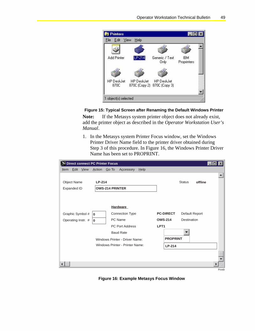
Operator Workstation Technical Bulletin 49
Figure 15: Typical Screen after Renaming the Default Windows Printer Note: If the Metasys system printer object does not already exist, add the printer object as described in the Operator Workstation User’s Manual.
1. In the Metasys system Printer Focus window, set the Windows Printer Driver Name field to the printer driver obtained during Step 3 of this procedure. In Figure 16, the Windows Printer Driver Name has been set to PROPRINT.
Print9
XItem Edit View Action Go To A cessoryc Help
Direct connect PC Printer Focus
Object Name Status offline
Expanded ID
Graphic Symbol #
Operating Instr. #
LP-214
Connection Type
Windows Printer - Printer Name:
PC Name
PC Port Address
Windows Printer - Driver Name:
Hardware
OWS-214 PRINTER
0
0
Default ReportPC-DIRECT
DestinationOWS-214
LPT1
Baud Rate
LP-214
PROPRINT
Figure 16: Example Metasys Focus Window

Operator Workstation Technical Bulletin 50
2. In the Metasys system Printer Focus window, set the Windows Printer Name to the Windows Printer Name obtained during Step 3 in this procedure. Figure 16 shows the Windows Printer Name is LP-214.
3. Save and close the Metasys Printer Focus window. Once the information is updated across the network, you can print to this device from any location in the network. Because this information is global data, it is not complete until all printers are configured.
Fixing Line Feed Problems when Using a Serial Printer If you are using a serial printer and are having line feed problems after setting up your printers, try changing the Printer Settings in the Properties dialog box.
To fix line feed problems when using a serial printer:
1. From the Start menu, select Settings and then select Printers. The Printers dialog box appears.
2. Right-click on the icon for the printer and select Properties.
3. Click the Details tab.

Operator Workstation Technical Bulletin 51
Figure 17: Properties Dialog Box with Details Tab Showing 4. Click the Spool Settings button to display the Spool Settings dialog
box.
Spool Settings X?
Cancel Restore efaultsDOK
Print14
Start printing fter first page is spooleda
Spool print jobs so program finishes printing faster
Print directly to the printer
Spool data ormat:f RAW
Start printing after ast page is spooledlStart printing after ast page is spooledl
Start printing fter first page is spooleda
Enable bi-directional support for this printer
D sable bi-directional support for this printeriD sable bi-directional support for this printeri
Enable bi-directional support for this printer
Figure 18: Spool Settings Dialog Box

Operator Workstation Technical Bulletin 52
5. Select the Print directly to the printer option and click OK to return to the Properties dialog box (Figure 18).
Note: If you still have problems, and the printer is on a COM port, skip to Step 11. If it is not on a COM port, try these additional steps.
6. Click the Port Settings tab to display the Port Settings dialog box.
7. Click the Advanced button to display the Advanced Port Settings dialog box.
Advanced Port Settings X
Print15
Use IFO buffers (requires 16550 compatible UART)F
Select lower settings to correct connection problems.Select higher settings for faster performance.
Receive Buffer: Low (1) High (14)
High (16)Transmit Buffer: Low (1)
Cancel
Defaults
OK
Figure 19: Advanced Port Settings Dialog Box 8. Click and drag the Receive Buffer and Transmit Buffer settings to
Low(1) (Figure 19).
9. Click OK to save the settings and return to the Advanced Port Settings dialog box.
10. Click OK to return to the Properties dialog box.
11. Click OK to close the Properties dialog box and save all settings.
Note: If your printer is on a COM port, look at the COM port status by viewing the Communications Port Properties dialog box. From the Start menu, choose Settings and Control Panel.
12. From the Control Panel dialog box, double-click on the System icon. The System Properties dialog box appears.
13. Click Device Manager. The Device Manager window appear (Figure 20).
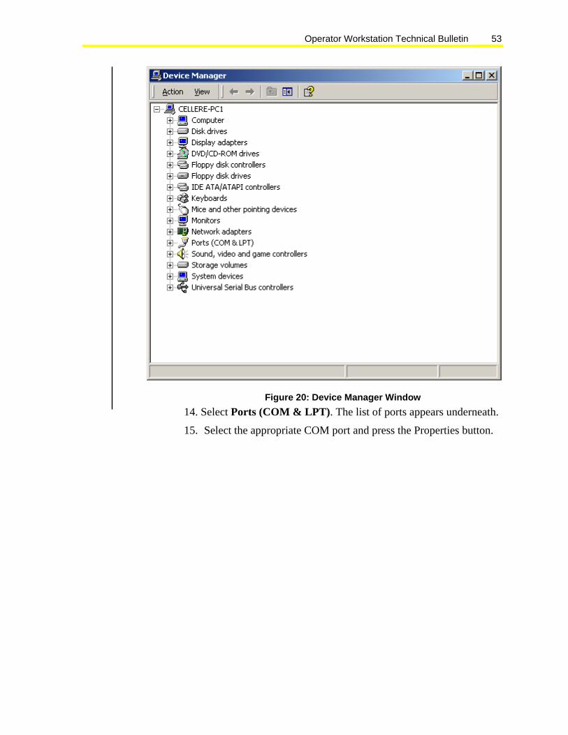
Operator Workstation Technical Bulletin 53
Figure 20: Device Manager Window 14. Select Ports (COM & LPT). The list of ports appears underneath.
15. Select the appropriate COM port and press the Properties button.

Operator Workstation Technical Bulletin 54
Figure 21: Communications Port Properties Dialog Box 16. Look under the Device status section on the screen for additional
troubleshooting information.
Connecting and Configuring a Modem to an OWS To connect and configure a modem to an OWS:
1. Connect a straight-through cable between the modem and workstation. To avoid disconnection, make sure the cable jackscrews are fastened.
2. Select PC Configuration. Figure 22 shows the PC Configuration screen with the Modem Setup button.

Operator Workstation Technical Bulletin 55
pcConfig
NETWORK MAP - PC Configuration
Device Type
NC Dial[modem]COM1
NC Direct
Printer
Mouse
NC Dial[ISDN]
Device Type
NC Dial[modem]COM2
NC Direct
Printer
Mouse
NC Dial[ISDN]
Device TypeCOM3NC Direct
Device TypeCOM4NC Direct
LPT1LPT2
OK
Cancel
ModemSetup
Baud Rate
1200
2400
4800
9600
14400
19200
28800
38400
57600
Baud Rate
1200
2400
4800
9600
14400
19200
28800
38400
57600
Baud Rate
1200
2400
4800
9600
14400
19200
28800
38400
57600
Baud Rate
1200
2400
4800
9600
14400
19200
28800
38400
57600
Figure 22: PC Configuration Screen 3. Select the Modem Setup button and the Modem Setup-PC
Configuration dialog box appears (Figure 23). The dialog box shows a communication port selection and a drop-down list box selection that displays a list of currently supported modems.
MODEM SETUP - PC Configuration
Cancel
Modem Port OK
COM1
COM2
modemselc
Practical Peripherals PM144MT II External
Figure 23: Modem Setup-PC Configuration Dialog Box

Operator Workstation Technical Bulletin 56
4. Select a communication port and a modem brand from the list box, and click OK to copy the selected modem setup string from the MODEM.INI file to the correct spot in the METASYS.INI file.
Note: After restarting the OWS, the modem is initialized with the desired setup string.
Connecting and Configuring a Modem to an NCM To connect and configure a modem to an NCM:
1. Connect a straight-through cable between the modem and the terminal. To avoid disconnection, make sure the cable jackscrews are fastened.
2. Use WNCSETUP and the Write Modem operation. Selecting Write Modem produces a dialog box similar to the one described previously for the OWS. Refer to the NCSETUP for Windows Technical Bulletin (LIT-6360251d) for details on Write Modem.
Adding User-Defined Modems Note: If the brand modem you are using is not listed, you may add the new modem to the MODEM.INI file. The file is located in the same directory as the METASYS.INI file.
To add user-defined modems:
1. Under the [OWS] section in the METASYS.INI file, find the User Defined Modem entry as shown in Figure 24 and create a new modem string definition by following the same format as the other modem definitions (Figure 24). The first line contains an asterisk followed by the modem name. The second and third lines contain the modem initialization string following the equal (=) sign.
For OWS modem entry: *ZOOM 56k External SetCom1ModemProfile=AT&FE0V0X3M1W0S0=1S109=0&C1&D2&Q5&W0&Y0 SetCom2ModemProfile=AT&FE0V0X3M1W0S0=1S109=0&C1&D2&Q5&W0&Y0
*Practical Peripherals PM144MT II External SetCom1ModemProfile=AT&FE0V0X3M1W0S0=1&C1&D2&W0&Y0 SetCom2ModemProfile=AT&FE0V0X3M1W0S0=1&C1&D2&W0&Y0 *User Defined Modem SetCom1ModemProfile=REPLACE THIS LINE WITH YOUR STRING SetCom2ModemProfile=REPLACE THIS LINE WITH YOUR STRING
Figure 24: Example of Excerpt from MODEM.INI File Note: While editing this section, remember to insert the new modem so a User-defined modem line still appears in the list box.
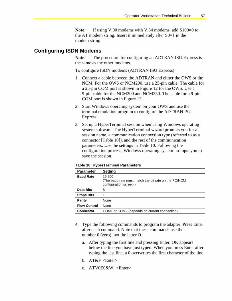
Operator Workstation Technical Bulletin 57
Note: If using V.90 modems with V.34 modems, add S109=0 to the AT modem string. Insert it immediately after S0=1 in the modem string.
Configuring ISDN Modems Note: The procedure for configuring an ADTRAN ISU Express is the same as the other modems.
To configure ISDN modems (ADTRAN ISU Express):
1. Connect a cable between the ADTRAN and either the OWS or the NCM. For the OWS or NCM200, use a 25-pin cable. The cable for a 25-pin COM port is shown in Figure 12 for the OWS. Use a 9-pin cable for the NCM300 and NCM350. The cable for a 9-pin COM port is shown in Figure 13.
2. Start Windows operating system on your OWS and use the terminal emulation program to configure the ADTRAN ISU Express.
3. Set up a HyperTerminal session when using Windows operating system software. The HyperTerminal wizard prompts you for a session name, a communication connection type (referred to as a connector [Table 10]), and the rest of the communication parameters. Use the settings in Table 10. Following the configuration process, Windows operating system prompts you to save the session.
Table 10: HyperTerminal Parameters Parameter Setting Baud Rate 19,200
(The baud rate must match the bit rate on the PC/NCM configuration screen.)
Data Bits 8 Stops Bits 1 Parity None Flow Control None Connector COM1 or COM2 (depends on current connection)
4. Type the following commands to program the adapter. Press Enter after each command. Note that these commands use the number 0 (zero), not the letter O.
a. After typing the first line and pressing Enter, OK appears below the line you have just typed. When you press Enter after typing the last line, a 0 overwrites the first character of the line.
b. AT&F <Enter>
c. ATV0E0&W <Enter>

Operator Workstation Technical Bulletin 58
5. Type AT!V. The ADTRAN PC or NCM configuration menu appears as follows. Verify that your settings match those in the figures.
Note: Lines 4 and 6 on the PC Configuration Menu show the phone number of the OWS. Line 4 shows the phone number with the area code and extension. Line 6 shows the phone number without the area code and extension (Figure 25).
ISU Express Configuration Menu (PC) 1) NETWORK options = Dial Line 17) CTS Options = Follows RTS2) Switch Protocol = DMS-100 18) CD Options = Normal 3) Call type = Data 64Kbps 19) DTR Options = Idle when
Off 4) SPID 1 = 41422727040111 20) DSR Options =DSR forced
on 5) SPID 2 = 21) Flow Control = Hardware
Flow 6) LDN 1 = 2272704 22) Data Bits = 8 Data Bits 7) LDN 2 = 23) Parity Bits = None 8) Dial options = AT commands 24) Stop Bits = 1 Stop Bit 9) Auto answer = Disabled 25) PROTOCOL = v.120 10) Answer tone = No Answer tone
26) QUICK Setup
11) Connect Timeout = 30 sec (def)
12) Call Screening = Answer any
13) Call Routing = All types->DTE
14) DTE options = Asynchronous 15) Bit Rate = 19200 16) RTS Options = 1 ms delay
Figure 25: ADTRAN Configuration for PC

Operator Workstation Technical Bulletin 59
Note: Lines 4 and 6 on the NCM Configuration Menu below show the phone number of the NCM. Line 4 shows the phone number with the area code and extension. Line 6 shows the phone number without the area code and extension (Figure 26).
ISU Express Configuration Menu (NCM) 1) NETWORK options = Dial Line
17) CD Options = Normal
2) Switch type = DMS-100 18) DTR Options = Idle when Off
3) Call type = Data 64Kbps 19) DSR Options = Off idle + test
4) SPID 1 = 41422727020111 20) Flow Control = Hardware Flow
5) SPID 2 = 21) Data Bits = 8 Data Bits 6) LDN 1 = 2272702 22) Parity Bits = None 7) LDN 2 = 23) Stop Bits = 1 Stop Bit 8) Dial options = AT commands 24) PROTOCOL = v.120 9) Auto answer = Enabled 25) QUICK Setup 10) Answer tone = No Answer tone
11) Connect Timeout = 30 sec (def)
12) Call Screening = Answer any
13) DTE options = Asynchronous
14) Bit Rate = 19200 15) RTS Options = 1 ms delay 16) CTS Options = Follow RTS
Figure 26: ADTRAN Configuration for NCM The ADTRAN ISU Express is programmed. Repeat Steps 1 through 4 for each adapter.
Installing the Microsoft Backup Utility Note: You must install Windows operating system software before installing the Microsoft Backup Utility.
To install the Microsoft Backup Utility:
1. Click the Start button on the Windows operating system taskbar. The Start menu appears.
2. Click the Settings > Control Panel menu option. The Control Panel appears.
3. Double-click the Add/Remove Programs icon in the Program Manager. The Add/Remove Programs Properties dialog box appears.
4. Click the Windows operating system Setup tab to bring it to the front of the dialog box (Figure 27).

Operator Workstation Technical Bulletin 60
Refer to the Windows NT Operating System or Windows 2000 Professional Operating System Details section in the Operator Workstation Appendix Technical Bulletin (LIT-1201696) for backup information.
Install/Uninstall
Components:
Startup DiskWindows Setup
To add or remove a component, click the check box. A shaded box means that only part of the component will be installed. To seewhat’s included in a component, click Details.
Cancel ApplyApplyOK
setup
? XAdd/Remove Programs Properties
Description
1 of 1 components selected
Includes options to change keyboard, sound, display, andmouse behavior for people with mobility, hearing and visualimpairments.
Details...
Space required: 1.6 MBSpace available on disk: 40.4 MB
Have Disk...
Accessibility Options 0.4 MBAccessories 4.2 MBCommunications 0.7 MB
Disk Tools 0.0 MBMicrosoft Exchange 4.6 MB
Figure 27: Add/Remove Programs Properties Dialog Box with Windows Setup Tab in Front

Operator Workstation Technical Bulletin 61
5. Click the check box next to Disk Tools and click the Details button to display the Disk Tools dialog box (Figure 28).
Disktol
Backup 1.2 MB
X
Cancel
Details...Details...
OK
Description
Space required:Space available on disk:
Components:
Disk Tools
To add or remove a component, click the check box. A shadedbox means that only part of the component will be installed. To see what’s included in a component, click Details.
2.7 MB40.0 MB
Program to backup and save data and files. Supports backupto floppy and tape drives.
Figure 28: Disk Tools Dialog Box with Backup Selected 6. Click the check box next to Backup to select it and click OK. The
dialog box closes and you return to the Add/Remove Programs Properties dialog box.
Installing Metasys PMI New Project Software Note: Verify all of the prerequisites in the Commissioning PMI New Project Software section and perform all of the setup activities, then continue with the installation steps below.
Do not use screen savers on Metasys workstations.
IMPORTANT: You must have administrative privileges to install Metasys PMI software on a PC running Windows 2000 Professional operating system or Windows XP Professional operating system. If not, an error message appears and you cannot install PMI.
To install Metasys PMI new project software:
1. Keep Windows operating system software running and close all other software applications.
2. Insert the Metasys PMI software CD into the CD-ROM drive.

Operator Workstation Technical Bulletin 62
3. Click the Start button on the Windows operating system taskbar. The Start menu appears.
4. Click the Run menu option. The Run dialog box appears.
5. Type d:/Setup in the Open box and press Enter. Use the appropriate drive letter for the CD-ROM drive. For example, if the CD-ROM is using Drive E, enter e:/Setup instead of d:/Setup.
6. Click the appropriate check box to select the software you want to install.
7. Select whether you want the program to automatically update your Autoexec.bat file, or whether you want to update it yourself later. If you select to have the file automatically updated, the changes are made directly to the Autoexec.bat file.
Note: If you select to not have the file updated automatically, the Autoexec.bat file is not changed. Instead, a new file containing the necessary changes is created. This file is named Autoexec.jci. It is your responsibility to add the necessary changes to the Autoexec.bat file at a later time. These changes are required for the Metasys N1 system to operate. If you are installing additional software, you must make these changes and reboot the PC before installing other software.
8. Select to reboot the PC.
Note: Some PCs may not automatically reboot. If a reboot does not occur within 10 seconds after clicking the reboot button, manually reboot the PC by pressing Ctrl\Alt\Del or by cycling power.
9. In the Logon dialog box, type METASYS, the default password, or type the password appropriate for the restored database to log on the network. If you wait too long, the slide show program begins to run. If this happens, press any key to return to the Logon dialog box.
The Metasys PMI installation is complete. You may now use the OWS functions. For instructions, refer to the Operator Workstation User’s Manual.

Operator Workstation Technical Bulletin 63
Note: The PMI Software installation process creates four temporary files. These may not be automatically deleted from the hard disk. Check both the WINDOWS and the TEMP directories for these files. Delete both the WINDOWS and the TEMP directories. (The TEMP directory location depends on the directory specified by the TEMP environment variable). The files that may be created are:
• ~INS0163.~MP
• ~INS0363.~MP
• ~INS0463.~MP
• ~INS0762.LIB
Installing Metasys PMI Upgrade Software Notes: If you are installing over Metasys system Release 5.2 or
earlier software, a database conversion is required. The conversion takes place automatically toward the end of the install program. Follow the onscreen instructions given for the conversion. Refer to the Database Conversion section in the Operator Workstation Appendix Technical Bulletin (LIT-1201696) for further information on the archive database conversion.
Verify all of the prerequisites in the Commissioning PMI New Project Software section and perform all of the setup activities, then continue with the installation steps below.
Do not use screen savers on Metasys workstations.
You must have administrative privileges to install Metasys PMI software on a PC running Windows 2000 Professional operating system or Windows XP Professional operating system. If not, an error message appears and you cannot install PMI.
To install Metasys PMI upgrade software:
1. Keep Windows operating system software running and close all other applications (for example, Metalink software and Microsoft Office).
2. Insert the Metasys system CD into the CD-ROM drive.
3. Click the Start button on the Windows operating system taskbar. The Start menu appears.
4. Click the Run menu option. The Run dialog box appears.
5. Type d:/Setup in the Open box and press Enter. Use the appropriate drive letter for the CD-ROM drive. For example, if the CD-ROM uses Drive E, enter e:/Setup instead of d:/Setup.

Operator Workstation Technical Bulletin 64
6. Click on the appropriate check box to select the software you want to install.
7. Select whether you want the program to automatically update your Autoexec.bat file, or whether you want to update it yourself later. If you select to have the file automatically updated, the changes are made directly to the Autoexec.bat file.
Notes: If you select to not have the file updated automatically, the Autoexec.bat file is not changed. Instead, a new file containing the necessary changes is created. This file is named Autoexec.jci. It is your responsibility to add the necessary changes to the Autoexec.bat file at a later time. These changes are required for Metasys software to operate. If you are installing additional software, you must make these changes and reboot the PC before installing other software.
A database conversion automatically occurs when upgrading from Metasys Release 5.2 software or earlier. Follow the onscreen instructions given for the conversion. Do not interrupt the conversion. Refer to the Database Conversion section in the Operator Workstation Appendix Technical Bulletin (LIT-1201696) for further information.
8. Select to reboot the PC.
Note: Some PCs may not automatically reboot. If a reboot does not occur within 10 seconds after clicking the reboot button, manually reboot the PC by pressing Ctrl/Alt/Del or by cycling power.
9. Cancel the Metasys software load on Windows operating system startup.

Operator Workstation Technical Bulletin 65
10. Verify that the Autoexec.bat file contains all the lines shown in the sample files provided in the Autoexec.bat and Config.sys Files in the Operator Workstation Appendix Technical Bulletin (LIT-1201696).
For information on the WIN.INI, METASYS.INI and SYSTEM.INI file parameters, refer to the Initialization Parameters Technical Bulletin (LIT-636345).
If the OWS is going to connect to the Metasys system via an Internet Protocol (IP) network, refer to the N1 Ethernet/IP Network Technical Bulletin (LIT-6360175) for additional configuration requirements.
11. Back up the converted database if a database conversion occurred (described in Step 7). Use the Windows operating system Backup Utility.
12. Type METASYS at the C:\> prompt and press Enter, or start Windows operating system software and click the Metasys system icon.
13. In the Logon dialog box, enter your password to log on to the network.
14. Perform a global download for each network (using the Action menu on the Network Map).
Note: If the Metasys system subnet (gate) address of any NCM is being changed, the NCM DDL file must be recompiled before the NCM is downloaded.
If upgrading from Release 5 software or earlier, run WNCSETUP to select a new download file (Lighting Control) for each NCM101 that has an Intelligent Lighting Controller (ILC) device.
15. Download all NCMs that are archived at this OWS with Code and Data. To download an NCM, select one NCM from the Network Map, display the Action menu, and select NC Download. In the Download dialog box, choose these options: Code and NC Data, and This PC. Download one NCM at a time. Wait for each download to complete before initiating the next download. During the download, the NCM is not controlling equipment.
16. Command desired Demand Limiting Load Rolling (DLLR) load groups to Shedding.
The Metasys PMI upgrade is complete. You may now use the OWS functions. For instructions, refer to the Operator Workstation User’s Manual.

Operator Workstation Technical Bulletin 66
Note: The install process creates four temporary files. These may not be automatically deleted from the hard disk. It is advised that you check both the WINDOWS and the TEMP directories for these files. Delete both the WINDOWS and the TEMP directories. (The TEMP directory location depends on the directory specified by the TEMP environment variable.) The files that may be created are:
• ~INS0163.~MP
• ~INS0363.~MP
• ~INS0463.~MP
• ~INS0762.LIB
Disabling the Parallel Port Check If the computer on which you installed PMI software does not have a physical parallel port (many server computers do not have one), you see an error in the event log when PMI first starts up. To eliminate the message perform the following procedure.
Note: This does not affect the operation of the computer if you are not attempting to write to a parallel printer.
Note: You must perform this process after PMI software is installed. If you reinstall PMI software for any reason, you must repeat this process. To install PMI software, see Installing Metasys PMI New Project Software.
To disable the parallel port check:
1. Use Windows Explorer and browse to C:\WINNT\System32\drivers and delete chklpt.sys.
2. Browse to C:\FMS\BIN and double-click on chklptu.reg. A dialog box appears and asks if you want to add the information in chklptu.reg to the registry.
3. Click Yes. A dialog box appears to tell you that the information was added.
4. Click OK.
5. Restart the computer.
The parallel port check is now disabled.

Operator Workstation Technical Bulletin 67
Troubleshooting Global Alarm Indicator Reset
Problem When upgrading from Metasys Person-Machine Interface (PMI) Release 11.00 or earlier to Metasys PMI Release 12.00, you may experience a problem with the Global Alarm Indicator (GAI) feature.
This problem may occur under the following circumstances:
• One or more workstations are upgraded without upgrading the Network Control Modules (NCMs).
• One or more workstations are upgraded from Metasys PMI Release 11.00 to Metasys PMI Release 12.00 without a subsequent NCM download.
• One or more NCMs are upgraded to Metasys PMI Release 12.00 before all Operator Workstations (OWSs) are upgraded to Metasys PMI Release 12.00.
Symptom The GAI feature was changed at Metasys (PMI) Release 12.00. As a result, if Network Control Modules (NCMs) running downloaded code at Metasys PMI Release 11.00 or earlier are used with an Operator Workstation (OWS) running Metasys PMI Release 12.00, the NCM may fail to send Global Alarm Indicator updates to the OWS under certain circumstances. This problem usually occurs during an upgrade of the network; however, if you have already upgraded all NCMs and OWSs to Metasys PMI Release 12.00 and are experiencing this problem or are unable to upgrade all the NCMs at this time, follow the procedure in the Solution section of this document.
Important: To avoid this problem with the GAI, upgrade all OWSs, then upgrade the NCMs. Complete system-wide upgrades as soon as possible. Do not leave NCMs and OWSs at different revisions of Metasys PMI.
Solution If you are experiencing this problem, before making any other changes, please verify the following:
1. Using Windows Explorer, open the Metasys.ini file.
2. Verify that the parameter EnaAlmind is set to 1. This line of the file should read EnaAlmind=1. If the parameter is set to 1, Skip Steps 3 through 5 and continue reading this section. If the parameter is set to 0 (zero), change it to 1 and continue with Step 3.

Operator Workstation Technical Bulletin 68
3. Save and exit the Metasys.ini file.
4. Shut down and restart Metasys PMI software.
5. Verify that the GAIs are now operational from all NCMs. If all GAIs are operational, you are done. If GAIs are still not operational, continue reading this section.
If you are experiencing this problem on an OWS that is connected via the N1 network or Network Controller (NC) Dial, see the N1 Network/NC Dial Connection section.
N1 Network/NC Dial Connection
Important: If Metasys PMI Release 12.00 or later is used with NCMs running Metasys software Release 11.00 or earlier, you must test the Global Alarm Indicators for each NCM at each OWS.
When testing the Global Alarm Indicators, if any alarm (red) indicator appears, the feature is working. If not, it is possible to recover using a special utility to reset the Global Alarm Indicator sign-up at the NCMs. This utility does not affect any process or other function running in the NCMs and works if a mixture of Metasys PMI Release 11.00 and Metasys Release 12.00 download code is running on the system.
To reset the Global Alarm Indicator, follow these steps:
1. Complete the upgrade to Metasys PMI Release 12.00 at the Metasys Operator Workstation (OWS).
2. Log on to Metasys PMI at the Metasys OWS and display the device summary.
3. Verify that all NCMs you are testing are online and have been online for several minutes. If some of the defined NCMs are offline, the process may require 30 minutes. In the case of dial-up connections, the modems must be connected for the entire time.
4. Use Windows Explorer to execute the program GAIRESET.EXE. This program is located in the directory C:\FMS\BIN.
Note: If all defined NCMs are online, the process should be complete in 5 minutes. If some of the defined NCMs are offline, the process may require 30 minutes. Several messages appear during this operation. The first message, Running NCM alarm indicator release, indicates the GAIRESET.EXE program has started. The last messages are Normal Completion — all done followed by Please restart Metasys now. Any other completion messages indicate a problem. Please contact the Field Support Center for assistance identifying the cause of any other completion messages.

Operator Workstation Technical Bulletin 69
Note: When the GAIRESET.EXE program finishes, the Metasys OWS software must be shut down and restarted. Once this is done, Global Alarm Indicators should work for the NCMs that were online.
Metasys N1 Ethernet Communication Problems After Any Metasys PMI Software Upgrade
Problem Network Control Modules (NCMs) and Operator Workstations (OWSs) on a Metasys N1 Ethernet Network go offline depending on their subnet mask after any Metasys PMI software upgrade. This communication problem occurs when you upgrade from any version of Metasys PMI software to any version of Metasys PMI software, because the install overwrites the Subnet_Mask parameter in the Metasys.ini file with 255.255.255.0.
Workaround Before you upgrade any version of PMI software, note the Subnet_Mask parameter in the Metasys.ini file. After the PMI upgrade, change the Subnet_Mask parameter in the Metasys.ini file back to the original subnet mask as noted before the upgrade.
If you have already upgraded the software, recover the subnet mask according to the following Windows 2000 operating system procedure.
Windows 2000 Operating Systems To recover the subnet mask on Windows 2000 operating systems:
1. From the Start menu, select Run. The Run dialog box appears (Figure 29).
Figure 29: Run Dialog Box 2. Type command in the Open text box and click OK. The DOS
Command Screen appears (Figure 30).

Operator Workstation Technical Bulletin 70
Figure 30: DOS Command Screen 3. At the C:\> prompt, type ipconfig and press Enter. The IP
Configuration information appears (Figure 31).
Figure 31: DOS Command Screen with IP Configuration Information 4. Note the subnet mask.
5. At the C:\> prompt, type exit and press Enter.
6. Change the Subnet_Mask parameter in the Metasys.ini file to the subnet mask noted in Step 4.
Controls Group 507 E. Michigan Street P.O. Box 423 www.johnsoncontrols.comMilwaukee, WI 53201 Published in U.S.A.