operator’s guide wa8 - daltons wadkin · 2.3 equipment parameter value china (non-ce) asien...
TRANSCRIPT

Operator’s GuideWA8
GBFWA8.0001
Version 1.0/2006
1
Foreword ...1Technical data ...3Machine identification ...3Machine data ...3Equipment ...5Characteristic noise values ...6Dust emission data ...6Intended use ...6Safety ...8Explanation of symbols ...8Health and safety instruction ...8Safety devices ...9Other risks ...15Working safely with the sliding table saw ...16Transport ...22Packing ...22Degree of dismantling ...22Sensitivity ...22Storage ...22Assembly ...23Installation of the sliding table saw ...23Sliding table assembly ...23Installation of table length extension ...23Electrical connection ...24Connection of extraction system (customer side!) ...26Rip fence ...26Machine configuration ...27Free cut adjustment of sliding table ...28Free cut adjustment of rip fence ...28Adjustment angle cut ...290° position of the saw blade ...30Machine operation ...31Tilting ...31Height adjustment ...31Changing the main saw blade ...32Saw blade recommendation ...33Table locking ...34Switching drives on and off ...35Motor protection ...35Scoring saw ...36Troubleshooting ...40Service ...42Lubrication ...43Brake ...43Customer service - spare parts ...44Single-sided mitre fence ...45Double-sided mitre-fence DUPLEX ...46

Foreword
1 Foreword
Safety instructions
– Do not wear loose clothing, gloves, neckties, rings,
bracelets or other jewelry which may get caught in
moving parts
– Nonslip footwear is recommend
– Wear protective hair covering to contain long hair
– NEVER STAND ON TOOL. Serious injury could oc-
cur if the tool is tipped or if the cutting tool is unin-
tentionally contacted.
– NEVER LEAVE TOOL RUNNING UNATTENDED.
Turn POWER OFF. Don’t leave tool until it comes to
a complete stop.
© ALTENDORF 2006 1

Foreword
Please read this Operator´s Guide through carefully before commisioning the saw since we donot accept liability for damage and disruptions to operating resulting from not adhering to thisOperator´s Guide!
Persons operating this sliding table saw, musthave had sufficient instruction and be suitably-qualified!
This Operator‘s Guide can thus not be regardedas a binding type description of the models in-volved.The Operator‘s Guide must always be available atthe location where the machine is being used andis tobe read and used by any person involved withworking with or on the machine, e.g.– operation, including upgrading, troubleshootingduring operation, rectification of productiondownti-
mes, services, disposal of operating andauxiliary materials– upkeep (maintenance, inspection, repair)– transport
In addition to the Operator´s Guide, national regu-lations on health and safety at work and environmentalprotection should to be noted.
Removal of the safety equipment, especially thesafety hood for the saw blade cover and the ri-ving knife, endanger the operator and lead toaccidents!
Safe working is only possible with a clean machineand a clean environment!
Reproduction, even of parts of this document,is only allowed with our permission!
© ALTENDORF 2006 2

Technical data
2 Technical data
2.1 Machine identification
The type label attached to the machine stand is used to determine the machi-ne identity and further important key data.Meaning of the specified designations:
MarksTo document that the machine complies with the basic health and safety requirements as defined in Ap-pendix I of Guideline 98/37/EWG for modifying Guideline 89/392/EWG (Machine Guideline) the machine is identified by the CE symbol.
2.2 Machine data
ManufacturerAltendorf QinhuangdaoMachinery Manufacturing Co. Ltd.No. 4 Hengshan Road,Economic & Technical Development Zone,Qinhuangdao 066004, P.R. China
MachineALTENDORF-sliding table sawType WA8Usable main blade diameter and associated cutting heights
* Not in CE-Version!** Only by option parallel safety hood!
Typ: Machine designationNummer: Machine-specific identification numbeBaujahr: Year of manufactureSägeblatt min Ø Diameter of the smallest permitted saw bladeSägeblatt max Ø Diameter of the largest permitted sawbladeFührungsschlitz-breite des Spaltkeils:
Diameter of the guide pins for the riving knife in the riving knife holder
Saw blade diameter [mm] 250 300 315 350* 400**Saw blade height vertical [mm] 0 - 55 0 - 80 0 - 87 0 - 105 0 - 130Saw blade height at 45° [mm] 0 - 38 0 - 56 0 - 60 0 - 73 0 - 91
© ALTENDORF 2006 3

Machine data
main saw Diameter of tool holder [mm]Tilting range of the saw blade [°]Idle speed [1/min]
300-463 / 4 / 5000
Scoring saw Diameter of scorer saw blade [mm]Diameter of tool holder [mm]Idle speed [1/min]
120228200
Machine table size of the machine table [mm] 900 x 702 ± 5Sliding table Lenght of the sliding table [mm] 1800, 3200Stops Cutting width at rip fence [mm]
Crosscutting at the crosscut fence [mm]1000 / 13003200
Extraction Connection pipe Ø under table [mm]Connection pipe Ø for upper safety hood [mm]Overall connection ØMin. speed of air [m/s]Min. volume flow [m3/h]Under-inflation [Pa]
120801402015001100
Environmental conditions Operating temperature [°C]Max. rel. humidity [%], no condensation!No gases of corrosive / explosive
10 - 4090
Weight Weight of machine [kg] ca. 850Electrical equipementDIN EN 60204
Voltage [V] + 5%, -10%Current [A]Frequency [Hz]Power of main saw motor [kW]Power of scoring saw motor [kW]
see type labelsee type labelsee type label5,50,75
The machine may basically only be connected to a 3 phase alternating current supplywith phases L1, L2, L3 since otherwise its braking module can be destroyed. If operatedwith phase converters, frequency converters or transformer-capacitor combinations thebraking modules andthe starter unit can be destroyed!
© ALTENDORF 2006 4
Equipment
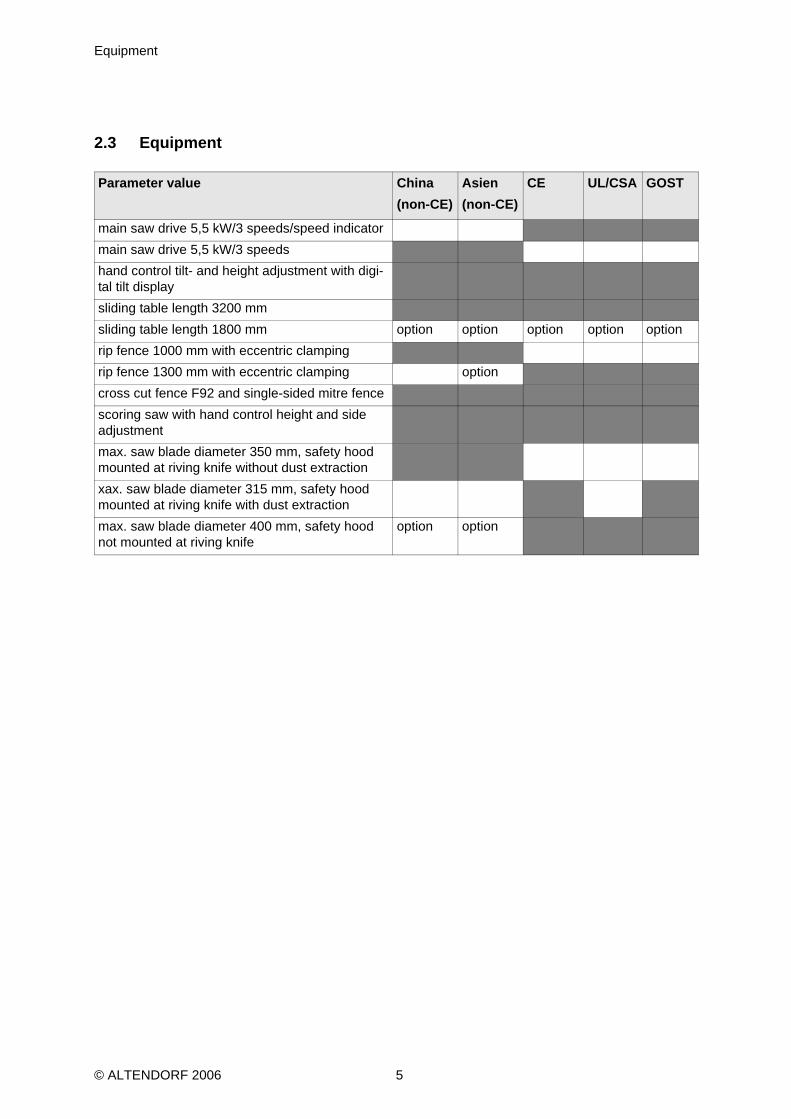
2.3 Equipment
Parameter value China(non-CE)
Asien(non-CE)
CE UL/CSA GOST
main saw drive 5,5 kW/3 speeds/speed indicatormain saw drive 5,5 kW/3 speedshand control tilt- and height adjustment with digi-tal tilt displaysliding table length 3200 mmsliding table length 1800 mm option option option option optionrip fence 1000 mm with eccentric clampingrip fence 1300 mm with eccentric clamping optioncross cut fence F92 and single-sided mitre fence scoring saw with hand control height and side adjustmentmax. saw blade diameter 350 mm, safety hood mounted at riving knife without dust extractionxax. saw blade diameter 315 mm, safety hood mounted at riving knife with dust extractionmax. saw blade diameter 400 mm, safety hood not mounted at riving knife
option option
© ALTENDORF 2006 5

Characteristic noise values
2.4 Characteristic noise values
The noise emission values determined according to EN 3746 for the sound power level or EN 11202(correction factor k3 calculated according to appendix A.2 of EN 11204) for the sound pressure levelba-sed on the working conditions listed in ISO 7960 appendix A amount to.:
A measuring error allowance of K = 4 dB (A) appliesto the specified emission values.The specified values are emission levels and therefore not necessarily levels for safe working. Althoughthere is a correlation between emission andemission levels, it cannot be reliably deduced fromthis whe-ther or not additional precautionary measures to protect the user are necessary. The current factors en-countered at the workingplace which influence the emission level, encompass the duration of theexposure, the room characteristics, other sources of noise such asneighbouring machines and the num-ber of neighbouring machines or other working processes involving noise emission. In addition, the per-missiblejudgement basis can vary depending on the country concerned.
2.5 Dust emission data
The workplaces at the sliding table saw are classedin accordance with BGI 739 Annex 4 as low-dustenvironments.
2.6 Intended use
The sliding table saw and the workpiece guide equipment suppliedis intended exclusively to be used forthe following purposes:– Cutting laminated and unlaminated sheet materials such as chipboard, woodworking boards, MDF
boards and material to be processed in a similar way– Solid wood– Veneer with suitable clamping– Gypsum– Paperboard– Processing of other materials such as nonferrous metals and compositematerials made of NF metals
and plastics requires our approval as regardsthe approval of the individual material and the saw bla-de intended for cutting it.
– Only use the machine to cut pieces which can be securly held and guided
Sound power level [dB (A)] Emission sound pressure level at the workplace [dB (A)]
Tool
Idle running LWA = 101,3Working LWA = 104,2
Idle running LPA = 95,7Working LPA = 92,1
saw blade 350 x 3,5 / 54 WZn = 3987 r.p.m
© ALTENDORF 2006 6
Intended use
Saw blades:– Care should be taken to choose the correkt saw blade for the job, whichwill depend (for example) on
whether you are ripping or crosscutting and the type of material being cut!– Only one-piece (CV) or composite (HM) circular saw blades of at least 250mm and maximum 315
mm diameter as well as routers/milling blades upto a cutting width of 15 mm are allowed for the mainsaw blade. Before using a milling cutter, remove the middle table strip and the cushioning disc!
– For the scoring blades saw blades of maximum 120 mm diameter are allowed.– The use of HS saw blades and oscillating router equipment is not allowed!
Site/use:– The machine is not suitable for operation in the open air, in damp environ-ments or in areas where
there is a danger of explosion.– Use of the machine according to specifications also includes connectionto a suitably dimensioned
industrial extraction system.– Adherence to the manufacturer’s specifications as regards operating,maintenance and servicing
conditions and following the safety precautionsgiven in the Operator’s Guide.– Sliding table saw may only be used, equipped and maintainedby persons who are familiar with the
unit and have been instructed in thedangers involved. Responsibilities for use, equipping and main-tenancemust be clearly defined. Service work must be carried out by our service department.
– The applicable accident prevention regulations as well as the other generally recognized safety andmedical rules applying to the workplace are tobe noted.
– Only original Altendorf spare parts may be used. The manufacturer doesnot accept any liability fordamage caused by using non-original spareparts. Modifications made to the machine by users andthe use of non-original parts on the machine exclude any liability by the manufacturer for anyresultingdamage.
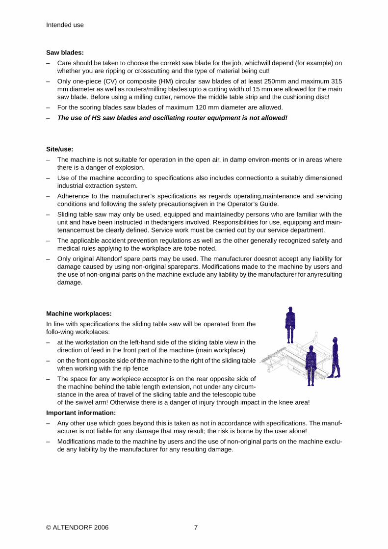
Machine workplaces:In line with specifications the sliding table saw will be operated from thefollo-wing workplaces:– at the workstation on the left-hand side of the sliding table view in the
direction of feed in the front part of the machine (main workplace)– on the front opposite side of the machine to the right of the sliding table
when working with the rip fence– The space for any workpiece acceptor is on the rear opposite side of
the machine behind the table length extension, not under any circum-stance in the area of travel of the sliding table and the telescopic tubeof the swivel arm! Otherwise there is a danger of injury through impact in the knee area!
Important information:– Any other use which goes beyond this is taken as not in accordance with specifications. The manuf-
acturer is not liable for any damage that may result; the risk is borne by the user alone!– Modifications made to the machine by users and the use of non-original parts on the machine exclu-
de any liability by the manufacturer for any resulting damage.
© ALTENDORF 2006 7

Safety
3 Safety
3.1 Explanation of symbols
You will find this symbol all information relating to health and safety in this Opera-tor’s Guide where there is a danger to life and limb. Please read this informationcarefully and take particular care in these cases. Please pass thesafety informa-tion on to other users. As well as the information in this guidethe generally-appli-cable safety and accident prevention instructions must be noted.
3.2 Health and safety instruction
Operating any machine tool, in particular woodworking machines with manual feed, involves a high risk if the machine is operated incorrectly. For this reason please always comply with the safety instructions summarized in this chapter as we as with official and other regulations governing health and safety at work (e.g. accident prevention regulations)!– Never operate the machine without using the protective equipment provid-ed for the procedure in-
volved (see also the section entitled "Safe use ofthe sliding table saw (- working examples -)" anddo not change anythingthat could affect safety.
– Check before working with the machine that the protective and operating equipment is securely at-tached and not damaged.
– Before changing tools, rectifying faults and during regular servicing work ensure that the machinecannot be turned on by mistake by securing the main switch with a padlock.
– Only saw blades and routing tools corresponding to European Norm EN847-1 may be used.– Only saw blades with the dimensions described in table 1 may be fitted.The diameter of the mounting
hole must be 30 mm in any event. Use of loose spacing rings is not permitted.– The speed must be chosen so that the highest reliable speed when thetool is equipped with hard
metal saw blades or routing cutters is not exceeded.– The use of HS saw blades and cracked or reformed saw blades is not permitted.– Always wear working clothes and remove rings, bracelets and watches..– Ensure that the workplace is unobstructed and that nothing slides around and that there is sufficient
lighting.– Do not work on any workpieces that are too large or too small for the powerof the machine.– Take up a working position so that you are always standing to the side ofthe saw blade outside a
possible recoil area (area directly in front of thesaw blade).– Before the machine is switched on loose parts must be removed from the immediate vicinity of the
saw blades.– Only start cutting when the saw blade has reached its full speed.– Always use the upper safety hood!– The upper safety hood must be set to the height that matches the thickness of the workpiece to be
cut. When working with a tilted saw blade replace the narrow hood with the wide hood.– Always use the riving knife except for insert cuts. It may not be thicker than the width of the cut and
thinner than the master blade. It is to be set so that the gap to the tooth tip is a maximum of 8 mm.Only riving knives may be used for which the slot width does not exceed 13 +0.5 mm. The suppliedriving knife covers the entire diameter range of the saw blades that can beused from 250 to 315 (350/400) mm. As regards their thickness they are matched tothe commercially-available carbide tippedsaw blades that are as wide as the cut. If other saw blades, e.g. CV saw blades are used, the widthof riving knife necessary must be selected so that this lies between the cut width and the main bladewidth. This type of riving knife is available in thetrade of directly from us.
– For cutting inserts a recoil protector should be used, e.g. the front side of the clamping shoe. This isto be attached in the groove of the sliding table where by the carriage with the clamp must be securedso that it does not move. After insert cutting the riving knife and the upper safety hood are tobe re-fitted immediately.
© ALTENDORF 2006 8

Safety devices
– Always ensure secure workpiece guidance and use the appropriate fences (rip fence, fence scale,crosscut fence on cross slides, cross stop).
– For lengthwise cutting of narrow workpieces (gap between saw blade and rip fence smaller than 120mm) the push stick must be used.
– Only make crosscuts with the cross slides attached to the sliding table. En-sure that the cut-off workpieces are not caught by the rising tooth tip and catapulted out.
– Cross cutting and lengthwise cutting of round-section wood is not allowed with the series feed aidsor fences.
– For trimming use the clamping shoe which is attached to the sliding table to hold down the workpiece.– If a feed device is used at least the riving knife should be employed for recoil protection.– Replace worn-out table bars immediately.– Use of an oscillating router or oscillating router milling tools is not allowed.– Only router milling tools that have a maximum width of 15 mm and are allowed for manual feed may
be used. With tools labeled “MAN“ this is guaranteed.– The noise level at the workplace generally exceeds 85 dB(A). For this reason wear ear defenders
when working.– The wood dust generated when working not only affects your vision butcan also be damaging to your
health in some cases. The machine must therefore be connected at both extraction sockets to a saw-dust extractor.The air speed at the lower extraction socket must be at least 20 m/s. Suitable measu-res must be taken to ensure that when the machine is switched on, the extraction system is switchedon at the same time (use of the floating contact).
– Work on the electrical parts of the machine may only be performed by electrical specialists.– Regular cleaning of the machine, particularly the table, the sliding tableand the guides (e.g. rip fence)
represents an important safety factor. Before starting such work you should ensure that the machinecannot be inadvertently switched on.
3.3 Safety devices
The machine is equipped with all the necessary safety devices to guard against any danger from it thatcould not have already been eliminated during construction. In particular these safety devices include:– The top safety hood (fixed to the riving knife) is made of high quality polycarbonate and designed to
optimally cover the section of the saw blade not used for cutting above the machine table. The startup slope at the front end of the safety hood simplifies the workpiece feed with different workpiecethicknesses.
– Or: Top parallel safety hood with narrow and wide protection hood made of polycarbonate for optimumcovering of the section over the machine table not required for saw cutting with protection againstlifting beyond the maximum cutting height + 5 mm. Rollers integrated at the leading and trailing endssimplify both the workpiece feed as well as pulling back in the case of slightly differing workpieces.
– 3 riving knifes for saw blades between 250 and 315 (350/400) mm diameter to avoid workpiece recoilthrough sticking in the kerf.
– Rip fence with scale adjustable in the direction of the cut: With drawable toavoid sticking of the cutlengths of workpiece between fence and rising tooth tip or adjustable to a lower feed surface for cut-ting narrower and flatter workpieces with sufficient space for manual feed, combined with the optionhere, too, of lowering the upper safety hood down to the workpiece.
– Trimming clamp to clamp and hold down untrimmed wood blocks to prevent slipping during trimming.– Holder device for the sliding table as security against workpiece slippage when cutting inserts in con-
junction with the crosscut fence.– Electrical locking of the cover plate on the dust channel below the machine table in the area of the
saw blades. When the cover plate is open it is not possible to turn on the machine and when themachine is running the drives are switched off if the cover plate is opened..
© ALTENDORF 2006 9

Safety devices
– Automatic brake which stops the main saw blade in less than 10 seconds after the machine is swit-ched off, regardless of the diameter and speed ofthe blade.
– Enhanced flow design of the sawdust catcher and of the upper safety hood to reduce dust emissionbelow 2 mg/m³, provided the machine is connected at both extraction sockets to an industrial extrac-tion system with at least20 m/s air speed.
– Good ergonomic design of the controls in easy-to-reach positions on the machine stand.
© ALTENDORF 2006 10

Safety hood
3.3.1 Safety hood
To protect the saw blade above the table, there must be an adjustable removable protection device. (DINEN 1870-1).
Safety hood mounted at the riving knife
Safety hood not mounted at the riving knife (only CE-version)Changing the safety hoodWhen working with a tilted saw blade replace the narrow hood with the wide hood.Never replace the safety hood when the saw blade is running!Replacing the safety hood:– after releasing the securing screw, pull the hood out forwards.– to fit it, place the safety hood in the hood carrier– push the safety hood up to the end until the two arrows are one above the other– tighten the securing screw
Hood carrier
Securing screw
Safety hood
© ALTENDORF 2006 11

Moving the safety hood out of the way
Moving the safety hood out of the wayYou may only work with the safety hood moved out of the way in special cases taking extra care,e.g. with bulky workpieces (carcass). When you have finished the safety hood is to be movedback immediately into its operating position!Move the safety hood as follows:– Switch off the main switch and prevent it from being switched on again– Release the clamping screw– The protective hood can be moved out of the wa
normal position safety hood in placeAfter you have finished move the safety hood back into its normal working position!
Lateral adjustment of the safety hood to the saw bladeAdjust the protective hood mount by moving it on tits arm so that there is a gap of max 15 mm between the edge of the protective hood and the spacer of the saw drive shaft.This setting is made at the factory and is marked by adjacent red arrows on the attachment bracket andthe arm.
© ALTENDORF 2006 12

Riving knifes
3.3.2 Riving knifes
The correct setting of the riving knife is of great importance for safety. The gap between the riving knifeand the toothed wheel of the saw blade may not be more than 8 mm in the area of the cutting height.The sensible gap in practice is around 5 mm. Use of the positively guided Altendorf riving knife automa-tically ensures with this gap that the height adjustment of the riving knife matches the tip appr. 2 mmbelow the uppermost tooth (see illustration)..Riving knife adjustment
Before adjusting the riving knife you must check whether its size and thickness match the saw bladebeing used. The series versions of the machine are supplied with the following riving knives: (range ofdiameters and thickness are stamped on the lower end of the knife in each case).250/2,5 for saw blade diameter of 250 mm and a body thickness of maximum 2.5 mm315/2.8 for saw blade diameter of 300 to 350 mm and a body thickness up to maximum 2.8 mm.300-350/2.8 for saw blade diameter of 300 to 350 mm and a body thickness up to maximum 2.8 mm, forconcealed cuts.400/3.2 for saw blade diameter of 400 mm and a body thickness up to maximum 3.2 mmThe thicknesses of the riving knife are selected so that they match the com-mercially available saw bladethicknesses in the relevant diameter range.Always switch off the main switch prior to setting the riving knife!To adjust the riving knife unlock the upper carriage and move it to its end po-sition and lift up the orangeprotective cover. The supplied special spanner can then be used to release the clamping bolt on the ri-ving knife holder. The riving knife can then be positioned at the correct height by moving it in its slot oradjusting the gap between it and the blade by moving the entire holder on the bar, noting the markingson the riving knife when doing this. Then retighten the clamping bolt and close the protective cover..
© ALTENDORF 2006 13

Table length extension
3.3.3 Table length extension
The table length extension prevents the workpiece tipping over after cutting and makes working safer.
3.3.4 Clamping shoe
The clamping shoe is used for trimming planks and fixes the workpiece securely on the sliding table.
3.3.5 Push stick
For cuts less than 120 mm the push stick must be used to prevent your hands getting near the saw bladewhen working. The push stick holder is located close to the work area on the rip fence.
3.3.6 Push block (through-sawing)
Push blocks should be used for cutting narrower workpieces and if necessary, for pressing the workpieceagainst the fence. A push block can easily be made by the operator and be fitted with the push blockhandle suppled with the machine.
Example of push stick(Dimensions in millimetres)
© ALTENDORF 2006 14

Kickback
3.3.7 Kickback
Do not use the crosscut fence and the rip fence at the same time. Use of both fences at once can causethe material to bind on the saw blade, resulting in a kick back.
3.3.8 Freehand
Do not cut freehand, use a hand or clamping devices for fixing the workpiece.
3.4 Other risks
Even when the machine is used in accordance with specifications, despite compliance with all safety reg-ulations, because of the construction of the machine which is determined by the purpose for which it isused, the following risks might still arise:– Touching the main saw blade and the scoring saw blade in the cutting area.– Touching the main saw blade and of the scoring saw blade below the table level when the sliding
table is right forward or right back.– Backstroke of the workpiece or of parts of the workpiece.– Catapulting off of individual teeth with carbide-tipped saw blades.– Breakage and spinning off of the saw blade.– Sticking between the motorized tilt movement of the saw blade and the rip fence or workpieces lo-
cated in the tilt area.– Contact with live parts when electrical installations are open– Long-term effects of noise when working for long periods without hearing protection– Emission of dust that can damage your health if operating the machine without dust extraction.– Avoid any dangers that may arise from these other risks by taking extra care when setting up, oper-
ating and maintaining the machine!
© ALTENDORF 2006 15

Working safely with the sliding table saw
3.5 Working safely with the sliding table saw
3.5.1 Cross slide / cross cut fence
Sizing and mitre cuttingThe cross slide is placed on the end bolts of the swivel arm and the circularbar of the upper carriage andclamped with the clamping screws. Depending on the size of the material to be handled this can be doneat any point on the upper carriage. For the mitre fence there are two positions on the cross slide..
Position 1 Use: For handling boardsThe operator pushes the workpiece in the cutting direction against the fence
cutting direction
Position 2Use: For handling wood and boards up to 600 mm widthThe operator pulls the workpiece against the cutting direction to the fence
cutting direction
© ALTENDORF 2006 16

Changing the cross cut fence
3.5.2 Changing the cross cut fence
– Lift the clamping lever and push to the inside (to release)– Bring the cross cut fence into a new position, ensuring that the centering bolts are engaged in the
holes– Lift the clamping lever and push to the outside– Push down the clamping lever (to clamp)
Note:For dimensions that have to be set with the hinged bar it shouldbe noted that the individual tilt stop is actually against the fenceof the cutout!
3.5.3 Rip fence
AdjustmentFor parallel cutting the rip fence is set to the desired dimension. The dimensionset is read off via theedge of the aluminum profile bar. The scale can be adjusted in accordance with the relevant tool thick-ness after the clamping screw has been released. For cuts less than 120 mm wide the material must be fed with a pushstick and the extended fencemust be in a flat position.The extended fence of the rip fence is adjustable in the cutting direction andin the profile height. It isclamped in the desired position using a star knob screw.CrosscuttingFor crosscutting shorter workpieces, for removal (e.g. tenon cutting) or other procedures in which piecesfalling off could jam between fence and saw blade, the extension fence is pulled far enough forward forits rear end to be in front of the saw blade.Flat and narrow workpiecesWhen handling flat and narrow workpieces the flat extension fence isused. This gives more space to gui-de the workpiece and the fence can be positioned closer to the saw blade, especially when the saw bladeis tilted, without hitting the safety hood.
Flat position of the extension fence Extension fence height adjustement
© ALTENDORF 2006 17

Working examples
3.5.4 Working examples
GeneralThe Altendorf sliding table saw is a universal machine which can be used for different cutting jobs. Todo this however it is necessary to equip the machine accordingly.ToolThe first important point is to only use undamaged saw blades, to correctly adjust the riving knife and tomove the upper safety hood so that it is positioned closely above the workpiece to be cut. This last pointis also of great importance for correct functioning of the extraction facility mentioned above.SpeedEnsure that the correct speed is set and after switching on the machine, only begin to push the workpieceforward when the saw blade has reached full speed.Position of handsThe hands lie flat with the fingers closed on the workpiece; the thumbs are adjacent with a sufficient safe-ty margin to the saw blade.You will find further notes on safe working in the following description of the individual work processes:
Edge cutting (trimming)Tool: Ripping circular saw bladOperation: Mount clamping shoe on the sliding table. Place workpiece hollow side down and press downwith clamping shoe. The ball of the right hand is used to apply forwards pressure to the edge of the work-piece. Place hands at a suitable safe distance from the tool.
Ripping of narrow workpieces(workpiece width < 120 mm)Tool: Ripping circular saw blade Operation: Adjust rip fence to the desired cutting width. Lower the safety hood in accordance with theheight of the workpiece. Move workpiece against the fence with the sliding table; use the push stick inthe area of the saw blade and push the separated workpiece until it is beyond the riving knife. For shortworkpieces use the push stick right from the start.
© ALTENDORF 2006 18

Working examples
Cutting of stripsTool: Circular saw blade for fine cutting Operation: Set the aluminum scale of the rip fence to the lower guide surface. Place the workpiece onthe sliding table and use your left hand to push it against the rip fence. Move the workpiece forward withthe sliding table, using the push block in the area of the saw blade and continue to push the strip until itis beyond the riving knife
Crosscutting of wide workpiecesTool: Circular saw crosscut blade:Operation: Place the workpiece against the mitre fence, use the left hand to press it firmly against thefence while moving it forward. When the flip stop is used, this is to be flipped up before pulling the work-piece back after cutting and the workpiece with drawn from the saw blade or the workpiece is only to beremoved beyond the rising blade tip.
Concealed cutting, rebating
Tool: Circular saw blade for fine cutting:Operation: For rebating select the cutting sequence so that the strip cut outfalls away on the side of thesaw blade opposite to the fence. Lower the safety hood onto the workpiece and ensure good workpieceguidance (left handpushes the workpiece against the rip fence.
© ALTENDORF 2006 19

Working examples
Concealed cutting, routingTool: Milling router permitted for manual feeding (maximum width 15 mm).Operation: Close the table opening by a table strip matched to the milling router. Set the tool to the desi-red routing depth. Leave the riving knife and the rear tool cover in place. On feeding push the workpiecefirmly onto the table (otherwise there is the danger of an unintentional insert process)For crossrouting of narrow workpieces always use the mitre fence.
Crosscutting against the rip fenceThe material is laid against the mitre fence of the cross slide. The desired dimension is set on the ripfence, the extension fence is pulled back to in frontof the saw blade after unclamping it and the item tobe cut moved with the sliding table. With the extension fence with drawn the workpiece can not stick be-tween saw blade and fence
Crosscutting short and narrow workpiecesTool: Circular saw blade for fine cutting:Operation: Set the magnetic guide piece (not included with the machine) so that workpiece offcuts can-not come into contact with the rising part of the sawblade. Only feed the workpiece using the mitre fence.Do not remove fallen pieces from the vicinity of the tool with your hands
© ALTENDORF 2006 20

Working examples
Dividing up large boardsWith this operation the dimension can be set either at the rip fence orat the mitre fence. If you wish tocut out many pieces with the same dimensions from a larger board, the best way to proceed is to firstcut off parallel strips at the rip fence and then cut these to the desired dimensions. However as soon asthe part pieces are greater than the cutting width of the machine the dimension is set at the mitre fenceof the machine.
© ALTENDORF 2006 21

Transport
© ALTENDORF 2006 22
4 TransportWhen transporting the sliding table saw with a crane or fork lift (only fixed lengthforks) only lift the machine a little and protect it from shocks!
4.1 Packing
The transport route is a deciding factor in the type of packing. Unless specifi-cally agreed otherwise, thepacking corresponds to the packing guidelines HPE laid down by the German body BundesverbandHolzmittel, Paletten, Ex-portverpackung e.V. and by the VDMA.The graphic symbols which appear on the packing should be complied with!
4.2 Degree of dismantling
The degree to which the sliding table saw is dismantled is governed by the transport conditions and bythe options available on the machine.Basically the sliding table saw is delivered divided into a number of installationmodules.
4.3 Sensitivity
Particular care should be taken when transporting the sliding table saw to prevent damage from externalforces or lack of care when loading and unloading.During transport buildup of condensation as a result of variations in temperature as well as shocks areto be avoided.
4.4 Storage
If the sliding table saw or the assembly modules are not assembled immediately after delivery they mustbe carefully stored at a protected location.When this is done they should be correctly covered so that no dust and no moisture can get in.The sliding table saw is delivered with a preservative for the bare, non-surface treated parts which pro-tects these parts for around 1 year. If it is stored beyondthis period further preservation measures shouldbe undertaken.

Assembly
5 Assembly
5.1 Installation of the sliding table saw
FoundationNo special foundation is required at the installation site for the sliding table saw. The floor must havesuitable load bearing capacity to take the weight ofthe machine, it must be even and level. If the machinerocks this should be remedied by putting a machine foot underneath it.Installation siteThe installation site for the machine should be selected so that, taking into account its space require-ments and the size of the workpieces to be handled, sufficient free space is available around the slidingtable saw. In addition the appropriate safe distances from parts of the building and from other machinesare to be adhered to so that there is no danger to the operator or to others of being trapped..
5.2 Sliding table assembly
– Before to assemble the lower carriage, disassembly the Emergency Stop:Switch cabinet after loosening the fastening screw rotate
– Position the lower carriage onto the machine frame and screw in place with the outer fixing screws.Push up against the stop screws prior to tightening!
– Middle fastening screw loos screw in– Position the middle carriage onto the lower carriage such that the locking system points to the right– Push the middle carriage to the right so that the 1st double roller is just resting on the round bars. – Carefully push on the top carriage ensuring that the top carriage does notjam and that the guide
rods are gently pushed onto the sliding table rollers– Push the top carriage firmly through up to the stop– Fit the rear stop and check that the stop on the top carriage and the stopon the bottom carriage si-
multaneously hit the end position, readjust if nec-essary.– Middle fastening screw screw tightly– Check the subrollers settings prior to starting up– Switch cabinet rotate back and screw tightly
5.3 Installation of table length extension
– Guide the pins of the table length extension into the holes on the face ofthe table plate– Secure loosely to the table plate with two M10 nuts and shake proof washers– Tighten the M10 nuts
© ALTENDORF 2006 23

Electrical connection
5.4 Electrical connection
All work on the electrical system, including connection to the power net-work, may only be performed by an electrical specialist. When working onthe electrical equipment the machine must be disconnected from the mainspower.
The junction box for the electrical connection of the sliding table saw is fitted at the side next to the ma-chine door. If the machine is connected via a flexible supply line (e.g. machines with travelling gear), arubber sheathed cable (wire marking H07RN-F) must be used.After the lead is connected the direction of rotation of the main saw mo-tor is to be checked bybriefly turning the machine on and if necessarycorrected by swapping two external leads in themains connection box.Note the arrow indicating direction of rotation on the saw blade cover!25A fuses are to be provided on the operating side!
Short description Description
Q1 main switchF1-2 fuse transformerT1 transformerF8 fuse transformerF4-6 fuse scoring saw motorE1 controlM1 main motorM2 scoring saw motorS1-3 safety limited switch
© ALTENDORF 2006 24

Electrical connection
In the event of a malfunction or breakdown, grounding provides a path of least resistance for electric cur-rent to reduce the risk of electric shock. This tool is equipped with an electric cord connector having agrounding plug. The cord connector must be properly installed and grounded in accordance with all localcodes and ordinances. Improper connection of the equipment-grounding conductor can result in a riskof electric shock. The conductor with insulation having an outer surface that is green with or without yel-low stripes is the equipment-grounding conductor. If repair or replacement of the electric cord or plug isnecessary, do not connect the equipment-grounding conductor to a live terminal. Check with a qualifiedelectrician or service personnel if the grounding instructions are not completely understood, or if in doubtas to whether the tool is properly grounded. Repair or replace damaged or worn cord immediately.USE PROPER EXTENSION CORD. Make sure your extension cord is in good condition. When usingan extension cord, be sure to use one heavy enough to carry the current your product will draw. An un-dersized cord will cause a drop in line voltage resulting in loss of power and overheating. Table showsthe correct size to use depending on cord length and nameplate ampere rating. If in doubt, use the nextheavier gage. The smaller the gage number, the heavier the cord.
The reference to the table and the table itself may be omitted if a statement indicating the appropriategage and length is incorporated into the instruction.
working space 900 mm
© ALTENDORF 2006 25

Connection of extraction system (customer side!)
5.5 Connection of extraction system (customer side!)
The minimum air speed at the extraction connection must be 20m/s. The extraction connection and thehoses are not supplied with the machine!It must also be ensured that when the machine is switched on the extraction system is also switched on!
5.6 Rip fence
5.6.1 Installing the table length extension
– Guide the bolts of the table length extension into the side holes of the tableplate– Secure loosely to the table plate with two M10 nuts and shake proof wash-ers– stove in the slotted spring pins– Tighten the M10 nuts
5.6.2 Installation of the rip fence
– Guide the stop bar with the threaded bolts into the holes in the table plate– Install the washers and nuts– Tighten the nuts– Install the belt scale– Push on the fence– Install the fence scale
© ALTENDORF 2006 26

Machine configuration
6 Machine configurationThe basic machine settings are made in the works during final assembly. Dismantling various modules,transport and assembly at the installation site can mean that it is necessary to correct the machine set-tings. The machine parts to be checked are described below.
Checking the lower rollers
Lower rollers on sliding tableThe lower rollers must move smoothly at the start and end of the running surface over the starting angle.They should be set so that they can be stopped manually by exerting a perceptible force and slide freelywhile the sliding table is moved.
Adjustment of the lower rollers
The lower rollers are supported eccentrically and adjustable. If they are set too tight the sliding table ishard to move.
Checking the main table
Main tablePlace a straight edge on the sliding table, carriage in mid position. Move carriage backwards and for-wards, main table must lie about 1/10mm lower.
Adjustment of the main table
Loosen the locknuts on the 4 fixed bolts, adjust the table plate, tighten the nuts. Then lay the straightedge in parallel to the sliding table on the main table.
© ALTENDORF 2006 25

Free cut adjustment of the sliding table
6.1 Free cut adjustment of the sliding table
Checking
Free cut adjustment of sliding tableSet saw blade to max. cutting height, cut a short piece of a test piece (where possible MDF) at the mitrefence. The difference in the noise between the cutting and non-cutting teeth allows you to determinewhether the sliding table is set correctly. On the passage of the rising teeth a slight fluttering noise shouldbe heard compared to the noise of the cutting teeth.
Adjustment
Release the sliding table attachment at both ends and in the middle (where present). Release the locknuts on the fence screws. Make the appropriate adjustments and retighten the lock nuts. Then readjustthe sliding table and tighten all securing screws again.
6.2 Free cut adjustment of the rip fence
Checking
Free cut adjustment of rip fenceSet saw blade to max. cutting height, cut a short piece of a test piece (wherepossible MDF) at the mitrefence. The difference in the noise between the cutting and non-cutting teeth allows you to determinewhether the sliding table is set correctly. On the passage of the rising teeth a slight fluttering noiseshouldbe heard compared to the noise of the cutting teeth.
Adjustment
Release the bolts connecting the table extension to the circular rod. Then, by adjusting the center lock-nuts, change the position of the circular bar and there by of the rip fence.When a scorer is used ensure that both free cuts are set to approximately the same!
© ALTENDORF 2006 26
Adjustment angle cut
6.3 Adjustment angle cut
Checking
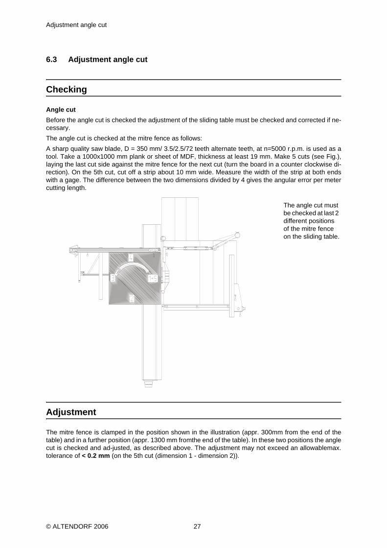
Angle cutBefore the angle cut is checked the adjustment of the sliding table must be checked and corrected if ne-cessary.The angle cut is checked at the mitre fence as follows:A sharp quality saw blade, D = 350 mm/ 3.5/2.5/72 teeth alternate teeth, at n=5000 r.p.m. is used as atool. Take a 1000x1000 mm plank or sheet of MDF, thickness at least 19 mm. Make 5 cuts (see Fig.),laying the last cut side against the mitre fence for the next cut (turn the board in a counter clockwise di-rection). On the 5th cut, cut off a strip about 10 mm wide. Measure the width of the strip at both endswith a gage. The difference between the two dimensions divided by 4 gives the angular error per metercutting length.
Adjustment
The mitre fence is clamped in the position shown in the illustration (appr. 300mm from the end of thetable) and in a further position (appr. 1300 mm fromthe end of the table). In these two positions the anglecut is checked and ad-justed, as described above. The adjustment may not exceed an allowablemax.tolerance of < 0.2 mm (on the 5th cut (dimension 1 - dimension 2)).
The angle cut must be checked at last 2 different positions of the mitre fence on the sliding table.
© ALTENDORF 2006 27

0° position of the saw blade
6.4 0° position of the saw blade
Checking
Lay 2 strips (appr. 70 mm wide) on edge in front of the mitre fence, cut them in this position and pushthe cut surfaces together. If the setting is exact, the cut edges are parallel, i.e. there is no air gap detec-table between the cut edges.
Adjustment
Recalibrate the machine!
© ALTENDORF 2006 28
Machine operation
7 Machine operation
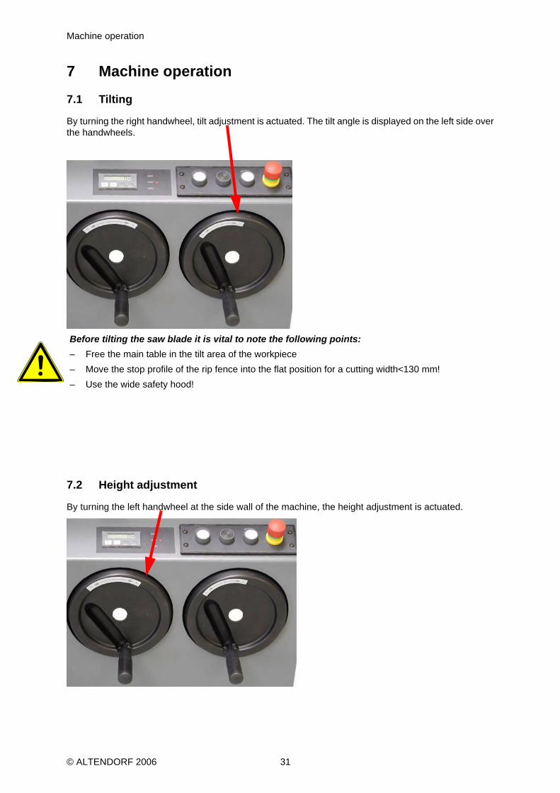
7.1 Tilting
By turning the right handwheel, tilt adjustment is actuated. The tilt angle is displayed on the left side overthe handwheels.
Before tilting the saw blade it is vital to note the following points:– Free the main table in the tilt area of the workpiece – Move the stop profile of the rip fence into the flat position for a cutting width<130 mm!– Use the wide safety hood!
7.2 Height adjustment
By turning the left handwheel at the side wall of the machine, the height adjustment is actuated.
© ALTENDORF 2006 31

Changing the main saw blade
7.3 Changing the main saw blade
The following basic points should be noted:– Do not fit any saw blades that have cracks or are damaged in any otherway. – Only fit saw blades with a diameter of between 250 and 315 mm (350/400) mm– Check that the speed set for the saw blade is not too high. For composite saw blades the highest
permitted speed is shown on the blade in the formn Max =... .Please note that only saw blades with adjacent holes (2 holes 10 mm ø spaced at 60 mm) can be ten-sioned. This is necessary to prevent the saw blade securing system becoming loose during braking.
Changing the saw blade– Switch off the drives– Set the saw blade to the upper height position and tilt it to 0°– Switch off the main switch– Guide the top carriage in the cutting direction, release the lock in the middle of the saw blade by
pressing the ball button on the middle carriage– Move the top carriage to the end in the cutting direction– Hinge up orange colour base plate– Bring bore holes in front flange into a vertical position– Secure saw blade against with retaining pin (bore hole for this purpose in machine table and saw
shaft)– Loosen saw shaft nut by turning clockwise (left-hand thread– Prior to fitting the new saw blade remove any adhering chips and dust from both flanges– Fit the saw blade and the front flange onto the saw shaft and tighten the saw shaft nut counter-clo-
ckwise– Remove retaining pin– Check that the thickness and spacing of the riving knife matches the saw blade– Close the bottom protection covering and check by way of a brief trial run that the saw blade runs
correctly. For this operation lower upper circular saw safety hood down to the table so that the sawblade is fully covered.
After the saw blade has been changed it is vital to make the correct riving knife adjustments!
© ALTENDORF 2006 32
Saw blade recommendation
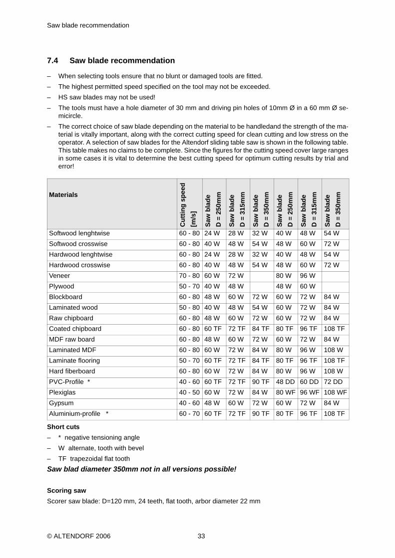
7.4 Saw blade recommendation
– When selecting tools ensure that no blunt or damaged tools are fitted.– The highest permitted speed specified on the tool may not be exceeded.– HS saw blades may not be used!– The tools must have a hole diameter of 30 mm and driving pin holes of 10mm Ø in a 60 mm Ø se-
micircle.– The correct choice of saw blade depending on the material to be handledand the strength of the ma-
terial is vitally important, along with the correct cutting speed for clean cutting and low stress on theoperator. A selection of saw blades for the Altendorf sliding table saw is shown in the following table.This table makes no claims to be complete. Since the figures for the cutting speed cover large rangesin some cases it is vital to determine the best cutting speed for optimum cutting results by trial anderror!
Short cuts– * negative tensioning angle– W alternate, tooth with bevel– TF trapezoidal flat toothSaw blad diameter 350mm not in all versions possible!
Scoring sawScorer saw blade: D=120 mm, 24 teeth, flat tooth, arbor diameter 22 mm
Materials
Cut
ting
spee
d [m
/s]
Saw
bla
deD
= 2
50m
m
Saw
bla
deD
= 3
15m
m
Saw
bla
deD
= 3
50m
m
Saw
bla
deD
= 2
50m
m
Saw
bla
deD
= 3
15m
m
Saw
bla
deD
= 3
50m
m
Softwood lenghtwise 60 - 80 24 W 28 W 32 W 40 W 48 W 54 WSoftwood crosswise 60 - 80 40 W 48 W 54 W 48 W 60 W 72 WHardwood lenghtwise 60 - 80 24 W 28 W 32 W 40 W 48 W 54 WHardwood crosswise 60 - 80 40 W 48 W 54 W 48 W 60 W 72 WVeneer 70 - 80 60 W 72 W 80 W 96 WPlywood 50 - 70 40 W 48 W 48 W 60 WBlockboard 60 - 80 48 W 60 W 72 W 60 W 72 W 84 WLaminated wood 50 - 80 40 W 48 W 54 W 60 W 72 W 84 WRaw chipboard 60 - 80 48 W 60 W 72 W 60 W 72 W 84 WCoated chipboard 60 - 80 60 TF 72 TF 84 TF 80 TF 96 TF 108 TFMDF raw board 60 - 80 48 W 60 W 72 W 60 W 72 W 84 WLaminated MDF 60 - 80 60 W 72 W 84 W 80 W 96 W 108 WLaminate flooring 50 - 70 60 TF 72 TF 84 TF 80 TF 96 TF 108 TFHard fiberboard 60 - 80 60 W 72 W 84 W 80 W 96 W 108 WPVC-Profile * 40 - 60 60 TF 72 TF 90 TF 48 DD 60 DD 72 DDPlexiglas 40 - 50 60 W 72 W 84 W 80 WF 96 WF 108 WFGypsum 40 - 60 48 W 60 W 72 W 60 W 72 W 84 WAluminium-profile * 60 - 70 60 TF 72 TF 90 TF 80 TF 96 TF 108 TF
© ALTENDORF 2006 33

Table locking
Riving knifeThe riving knives supplied are suitable in size for the range of saw blade diameters specified in the table.The corresponding range is specified on the bottom end of the relevant riving knife.The thickness of the riving knife is however only correct where the blades concerned are commerciallyavailable carbide-tipped saw blades. For CV saw blades other riving knives are required.
7.5 Table locking
The sliding table lock automatically blocks the sliding table in its end position,so that the items for cuttingcan be pushed against the mitre fence without any un desired movement of the easy to move slidingtable. The table is unlocked by turning the lever at the end of the upper carriage by hand.
With an additional locking adjustment the sliding table can be blocked in its center setting with the car-riage lock.
unlocking lever
© ALTENDORF 2006 34

Switching drives on and off
7.6 Switching drives on and off
Before switching on the machine ensure that all the necessary protective de-vices for the relevant ope-ration are fitted and operational. Also check that thesaw blades are correctly tensioned and that there isno workpiece or other ob-jects in their vicinity. Check that the correct speed for the saw blade and fortheoperation to be performed has been preselected. Check by switching onbriefly that the circular saw bladeis rotating in the right direction.Ensure that when you switch the machine on you are simultaneously switchingthe extraction system on.
7.7 Motor protection
If the motor protection cuts in it is a sign that the motor is being overloaded and the cause must be iden-tified and rectified before the machine is switched backon (e.g. blocking of the drive by a jammed work-piece, feed too great or failure of a mains phase).The drive motors are protected against overload by a coil protection. If the motor gets too hot this auto-matically switches the motor off. Note here that for machines with scorers this drive is switched off aswell, even if this motor was not overloaded. The machine cannot be switched back on until the motor hascooled down. The motor can take several minutes (max. 10 minutes) to cooldown!
© ALTENDORF 2006 35

Scoring saw
7.8 Scoring saw
The Altendorf scoring saw was developed to enable boards coated on both sides to be cut on the under-side without damage.The material is only cut into by around 1-2 mm by the scorer or the underside and then separated fromthe main sheet. The blade of the scorer must be precisely aligned to the main blade and set to the cor-responding width.– Two-piece scorer blades are to be recommended which are adjusted tothe required blade strength
by insertion of distance pieces. The cutting widths of the scorer blades should be at least. 1/10 mmwider than those of the main blades, i.e., 5/100 mm to each side. In addition the two scorer bladesshould feature driver pins and the width should be printed on the spacers.
– The scorer saw can only be started after the main saw has reached its operating speed (after around5 seconds.), by pressing the white button I which is also located in the panel and identified by thesymbol for the scoring saw..
AdjustmentHeight and lateral adjustments are made mechanically and can be performedwhen the machine is run-ning.
Height adjustment Lateral adjustment
© ALTENDORF 2006 36

Saw blade change
7.8.1 Saw blade change
The description of saw blade change only applies to divided scorer saw blades and also to saw bladeswith stepless cutting width adjustment. Only use sawblades with a diameter of 120 mm and 22 mm arbordiameter– Switch off the drives– Move scoring saw into its highest position– Move sliding table in cutting direction– Unlock the lock in the middle of the saw blade by pressing the spherical button on the center carriage– Move the sliding table into its end position in the cutting direction– Raise lower protective hood (orange hood)– Release the securing screws by turning them to the left– Before fitting the new scorer saw blade clean off any sawdust adhering to the two flanges– Place the saw blade and front flange on the saw drive shaft and tighten the nut in a clockwise direc-
tion
In addition the following points should be noted when using RAPIDO scorer saw blades with steplesscutting width adjustment:– Ignoring the operating instructions reduces operational safety impermissibly and leads to exclusion
of liability– max. speed = 9000 rpm– Permitted cutting width 2,8 - 3,8 mm– The adjuster unit must be unpacked and packed with particular care, danger of injury!– Only store the adjuster unit in its original packing!– The scorer saw blade must be installed outside the machine– All connecting elements must be installed– If the connecting elements are lost or damaged only original spare partsmay be used as replace-
ments!
© ALTENDORF 2006 37

Adjustment of the saw blade width of the scoring saw
7.8.2 Adjustment of the saw blade width of the scoring saw
Standard saw blade– Use spacers to bring the scorer saw blade to the width which is 0.1 mm greater than the width of the
main saw blade– Set the alignment of the scorer to the main saw first on the table plate side– Test cut– Set the alignment on the left side by adding or removing intermediate rings
Saw blade with stepless cut width adjustment RAPIDOFor adjustment only use the provided tools!– Release the clamping screw, appr. 2 turns– Turn the spindle until the desired dimension is reached. (1 turn = 0.5 mm)– Tighten the clamping screw– Test cut, if necessary correct the cutting width again as described above.
Replace scoring saw blades for RAPIDO– Take the adjuster unit off the machine; the clamping screw may have to bereleased since a tightened
clamping screw can cause the adjuster unit tojam on the shaft!DismantlingWith allen wrench:– Release clamping screw (1) appr. 3-4 turns, rotate spindle (2) clockwise until the flange (3) can be
pulled away from holder (4)With internal torx key:– Unscrew screws (5)– Remove circular saw blade (6)– Fully clean flange (3) and screws (5). The running and flange surfaces must be clean and dust free.– Fit a new circular saw blade, note direction of rotation and arbor image when fitting: The circular saw
blade (6) lies flat on the flange (3)and the protrusion on the circular saw blade points to the contact-surface
– Screw in screws (5) and tighten to a torque of 8,6 Nm– Proceed in the same way with the other half of the adjuster unitAssembly:Do not oil or grease– Clamping screw (1) is released– Place flange (3) horizontally on the holder (4) so that the spindle (2) engages in threaded hole (7)– Use the hexagonal key to turn the spindle (2) in a counterclockwise direction. The flange (3) will be
pulled into the holder (4) no additional force may be used here.
release the clamping screw turn the spindle
© ALTENDORF 2006 38

Saw blade with stepless cut width adjustment RAPIDO
– Continue to turn spindle (2) until the two halves of the circular saw blade are lying against each other– Install the adjuster unit on the machine– Setting the cutting width, see above– Only turn clamping screw (1) slightly
© ALTENDORF 2006 39
Troubleshooting
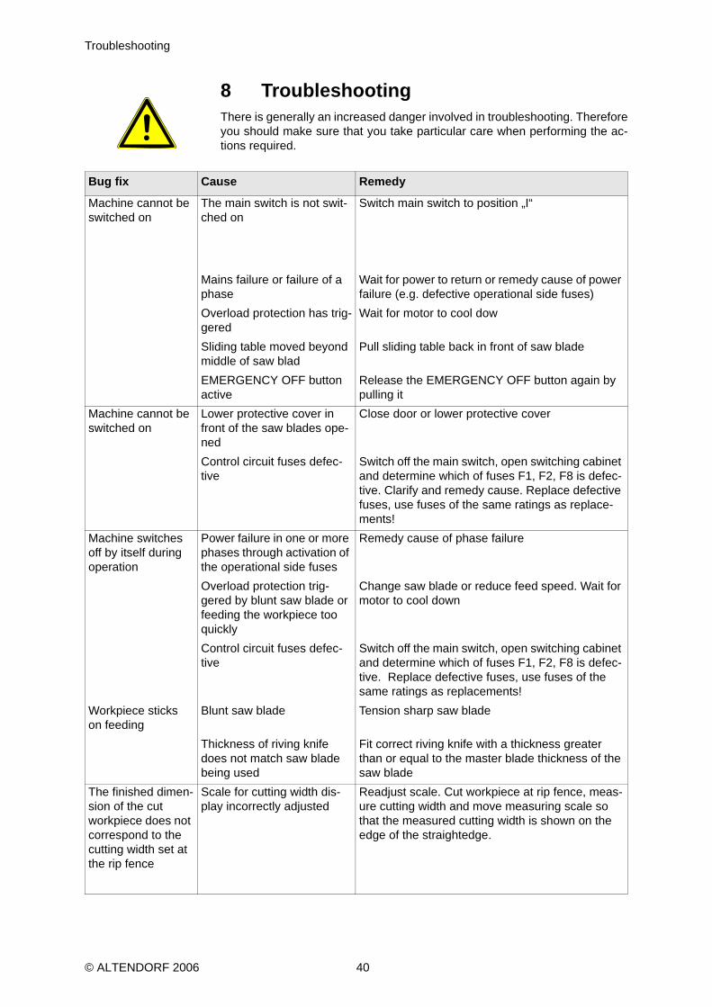
8 TroubleshootingThere is generally an increased danger involved in troubleshooting. Thereforeyou should make sure that you take particular care when performing the ac-tions required.
Bug fix Cause Remedy
Machine cannot be switched on
The main switch is not swit-ched on
Switch main switch to position „I“
Mains failure or failure of a phase
Wait for power to return or remedy cause of power failure (e.g. defective operational side fuses)
Overload protection has trig-gered
Wait for motor to cool dow
Sliding table moved beyond middle of saw blad
Pull sliding table back in front of saw blade
EMERGENCY OFF button active
Release the EMERGENCY OFF button again by pulling it
Machine cannot be switched on
Lower protective cover in front of the saw blades ope-ned
Close door or lower protective cover
Control circuit fuses defec-tive
Switch off the main switch, open switching cabinet and determine which of fuses F1, F2, F8 is defec-tive. Clarify and remedy cause. Replace defective fuses, use fuses of the same ratings as replace-ments!
Machine switches off by itself during operation
Power failure in one or more phases through activation of the operational side fuses
Remedy cause of phase failure
Overload protection trig-gered by blunt saw blade or feeding the workpiece too quickly
Change saw blade or reduce feed speed. Wait for motor to cool down
Control circuit fuses defec-tive
Switch off the main switch, open switching cabinet and determine which of fuses F1, F2, F8 is defec-tive. Replace defective fuses, use fuses of the same ratings as replacements!
Workpiece sticks on feeding
Blunt saw blade Tension sharp saw blade
Thickness of riving knife does not match saw blade being used
Fit correct riving knife with a thickness greater than or equal to the master blade thickness of the saw blade
The finished dimen-sion of the cut workpiece does not correspond to the cutting width set at the rip fence
Scale for cutting width dis-play incorrectly adjusted
Readjust scale. Cut workpiece at rip fence, meas-ure cutting width and move measuring scale so that the measured cutting width is shown on the edge of the straightedge.
© ALTENDORF 2006 40
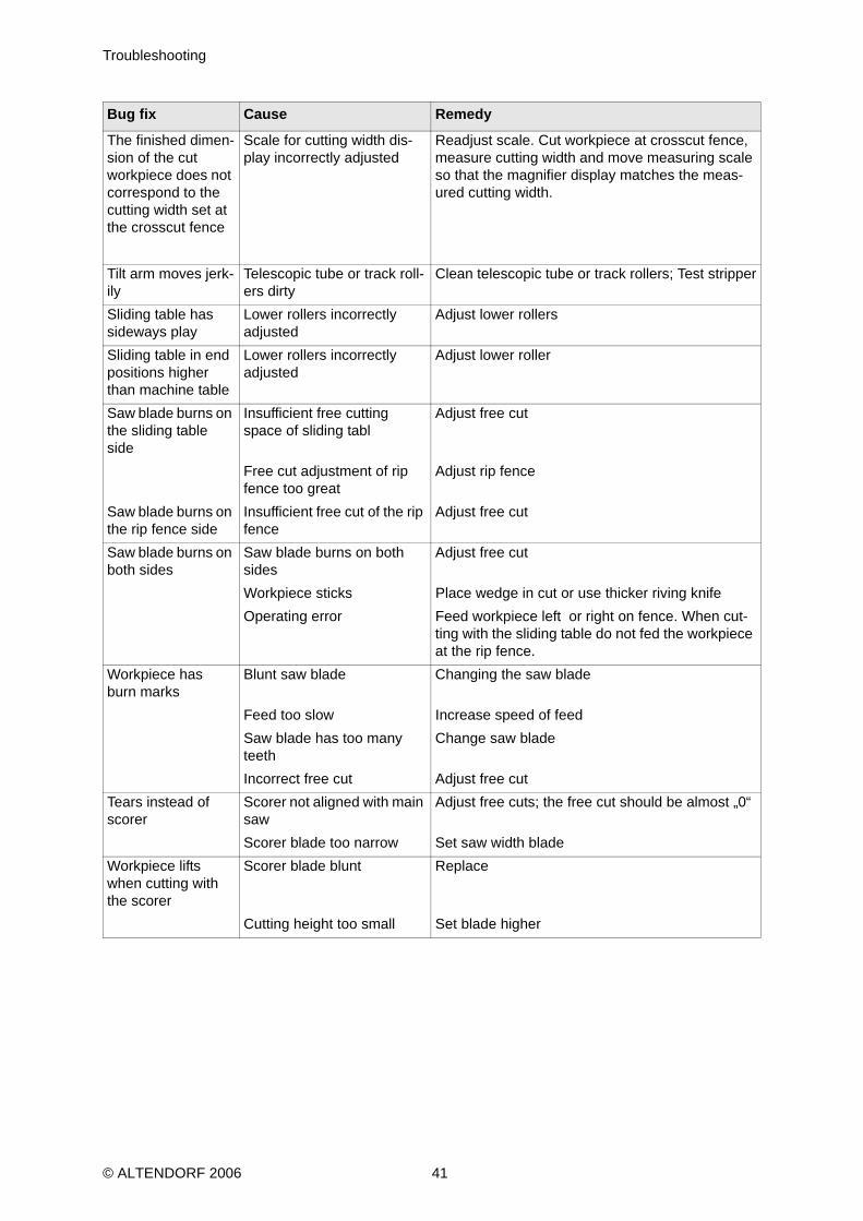
Troubleshooting
The finished dimen-sion of the cut workpiece does not correspond to the cutting width set at the crosscut fence
Scale for cutting width dis-play incorrectly adjusted
Readjust scale. Cut workpiece at crosscut fence, measure cutting width and move measuring scale so that the magnifier display matches the meas-ured cutting width.
Tilt arm moves jerk-ily
Telescopic tube or track roll-ers dirty
Clean telescopic tube or track rollers; Test stripper
Sliding table has sideways play
Lower rollers incorrectly adjusted
Adjust lower rollers
Sliding table in end positions higher than machine table
Lower rollers incorrectly adjusted
Adjust lower roller
Saw blade burns on the sliding table side
Insufficient free cutting space of sliding tabl
Adjust free cut
Free cut adjustment of rip fence too great
Adjust rip fence
Saw blade burns on the rip fence side
Insufficient free cut of the rip fence
Adjust free cut
Saw blade burns on both sides
Saw blade burns on both sides
Adjust free cut
Workpiece sticks Place wedge in cut or use thicker riving knifeOperating error Feed workpiece left or right on fence. When cut-
ting with the sliding table do not fed the workpiece at the rip fence.
Workpiece has burn marks
Blunt saw blade Changing the saw blade
Feed too slow Increase speed of feedSaw blade has too many teeth
Change saw blade
Incorrect free cut Adjust free cutTears instead of scorer
Scorer not aligned with main saw
Adjust free cuts; the free cut should be almost „0“
Scorer blade too narrow Set saw width bladeWorkpiece lifts when cutting with the scorer
Scorer blade blunt Replace
Cutting height too small Set blade higher
Bug fix Cause Remedy
© ALTENDORF 2006 41
Service
9 ServiceBefore performing any maintenance always switch off the main switchand prevent it from beingswitched on again!Regular cleaning of the machine extends its working life and is also a requirement for problem-
free cutting. The sliding table saw should therefore, depending on how dirty it is, be cleaned atleast once a week. Theparticular are as affected are:the machine tablethe sliding tablethe sliding table guidesthe tilting segmentsthe bar of the rip fencethe interior of the machinethe machine environment
Sawdust and dust adhering is removed with a vacuum cleaner. To remove resin residues it is best to usea cleaning solvent. It is essentialthat parts treated in this way are treated afterwards with an oil-soaked-cloth to avoid the buildup of rust.
The sliding table guides are to be cleaned regularly. If contaminatedwith resin, the guides are to be clea-ned with petroleum and possibly using Scotch Brite pads for example. It is not advisable to use steelwoolor sandpaper since this than irreparably damages the guide tracks.
Before using a solvent and cleaner you must make sure that this substance will not cause anydamage to the lacquered, anodized or zincplated surfaces as well as to plastic parts. You canobtain information about this by consulting the safety data sheets for this substance (obtainablefrom makers of solvents or cleaners).
© ALTENDORF 2006 42

Lubrication
9.1 Lubrication
9.1.1 Saw drive shaft
The bearings of the main saw shaft and the scorer saw shaft are sealed for life so that no subsequentlubrication is needed.
9.1.2 Tilt segments
The tilt segments are to be cleaned and lubricated on a regular basis. The intervals for such work (2weeks) depend on the period of use.
9.2 Brake
The electronic brake of the main saw unit is not subject to wear!
© ALTENDORF 2006 43

Customer service - spare parts
© ALTENDORF 2006 44
10 Customer service - spare partsHolding a stock of the most important spares and parts that wear out is an important prerequisite for theongoing function and availability of the sliding table saw.
To order spare parts please use the spare parts list.
The spare parts codes entered in the spare parts list provide further information.
We only accept a guarantee for original spare parts supplied by us.
We would explicitly point out that spare parts and accessories not originally supplied by us are not testedand released by us. Fitting and/or use of such products can therefore under some circumstances nega-tively affect the characteristics specified by the construction of the sliding table saw and thereby adver-sely affect active and/or passive safety. No liability or warranty claimsare accepted by Wilhelm AltendorfGmbH & Co KG for damage arising fromuse on non-original spare parts.
Please note that there are often special manufacturing and delivery specific-tions for own and third-partyparts and that we always supply you with spareparts to the latest technical specification and in line withthe latest official regulations.
When ordering spares please quote the following information:
Machine number.
Article-No.
Our address for spare parts sales and customer service::
Wilhelm Altendorf GmbH & Co KGService department
Wettinerallee 43 / 45 Postfach 20 09
D-32429 Minden D-32377 Minden
Telefon:+49 571/95500Telefax:+49 571/9550111

Single-sided mitre fence
© ALTENDORF 2006 45
11 Single-sided mitre fenceThe eccentric clamping system of the fence allows it to be fast and easily fitted to the sliding table. Max.length to cut: 2500 mm. The throw-over stops are of a sturdy, backlash-free and easy adjusting design.DDimension scales are inclined to enhance visibility for the operator.
Clamping lever Angle scale Clamping screwChanging:– Pull up the clamping lever and the clamping screw to loosen– Adjust the angle– Apply light pressure and push down the clamping lever and tighten the clamping screw to clamp

Double-sided mitre-fence DUPLEX
12 Double-sided mitre-fence DUPLEXBasic settings
Abb. 12-1: Test cut
– Set the DUPLEX to a 90° angle and lock it– Set the first stop to a distance 200mm from the saw blade and fix it– Cut test piece and measure it ( for example 201mm)
Abb. 12-2: Adjustment flip stop
– Adjust the scale of lenght so that the marker of the magnifiying glass corresponds to the test reading(201mm). The scale can be adjusted by exerting slight pressure on its center point and moving it
– Adjust flip stop to 200 mm
Abb. 12-3: Adjustment scale
– loosen scews of the compensation scale with Allan key 2,5– Remove scale of length compensation so that the 0° mark correspnds to the marker on the flip stop– Tighten screws of compensation scale with Allan key 2,5mm
© ALTENDORF 2006 46

Double-sided mitre-fence DUPLEX
THIS PROCESS GOES FOR BOTH SIDES!
Cutting using length compensation
Abb. 12-4: Adjustment angle
– Adjust cutting angle according to scale, for example 22,5°
Abb. 12-5: Adjustment flip stop
– Adjust marker on stop holder to the same angle
Abb. 12-6: Adjustment scale
– Adjust scale of lenght so that the marker of the red reference point „20“ corresponds to the markeron the magnifying glass
– The scale of length has now been adjusted to the corresponding angle of 22,5°– Now the requested measure of length can be adjusted
© ALTENDORF 2006 47