operator’s manual - issue 1 - p&m aviation · 2016-07-21 · p&m quikr manual, ref. quikr...
TRANSCRIPT
Operator’s Manual - Issue 1.4
P&M Aviation Ltd. Elm Tree Park, Manton, Marlborough, Wiltshire SN81PS email: [email protected] www.pmaviation.co.uk
SERIAL NO:

P&M QUIKR Manual, ref. QUIKR Man 1.4.doc Page 2
TABLE OF CONTENTS PAGE 1. Preparation for Safe Microlight/Ultralight Operation 8 1.1. Training 8 1.2. Pre-flight Planning 8 1.3. Modifications 10 1.4. Pre-flight Checks 10 1.5. Safety Harness 10 1.6. Ground Handling 10 1.7. Airstrip Criteria 10 1.8. Special Hazards 11 2. General Description 13 2.1. General Arrangement Drawing 13 2.2. Primary Structures and Systems - The Wing 14 2.3. Primary Structures and Systems - The Trike 15 2.4. Secondary Structures and Systems - Engine Controls 17 2.5. Secondary Structures and Systems - Braking System 18 2.6. Secondary Structures and Systems - Fuel System 18 2.7. Secondary Structures and Systems - Seat Belts 19 2.8. Secondary Structures and Systems - Cockpit and Fairing 19 2.9. Secondary Structures and Systems - Electrical System 19 2.10. Secondary Structures and Systems - Carburettor Heat 19 2.11. Secondary Structures and Systems - Radiator Covers 20 2.12 Secondary Structures and Systems - Trim 21 3. General Information 22 3.1. Empty Weight 22 3.2. Fuel Loads 22 3.3. Centre of Gravity 23 3.4. Dimensions 23 3.5. Powerplant Specifications 24 3.6. Running Gear 24 3.7. Placards, Decals and Locations 24 3.8. Performance 25 3.9. Electrical System Specification 27 4. Operating Limitations 29 4.1. General Limitations 29 4.2. Powerplant Limitations 30 4.3 ASI calibration 30 5. Rigging the Aircraft 31 5.1. General 31 5.2. Wing Rigging 32 5.3. Preparing the Trike 38 5.4. Connecting the Wing to the Trike 39 6. Pre-flight Inspection 41 6.1. Wing 41 6.2. Trike 41
P&M QUIKR Manual, ref. QUIKR Man 1.4.doc Page 3
7. Preparation for Flight 42 7.1. General 42 7.2. Strapping In 43 7.3. Starting Engine 43 7.4. Engine Warm Up 45 8. Flight 46 8.1. General Flight Control 46 8.2. Primary Controls 47 8.3. Ground Handling 48 8.4. Take-Off 49 8.5. En-Route 51 8.6. Landing 53 8.7. Emergency Procedures 54 9. Post-Flight Inspection 56 10. De-Rigging the Aircraft 57 10.1 Fold configuration 1 57 10.2 Fold configuration 2 58 10.3 Fold configuration 3 60 10.4. Rigged Wing Storage 61 10.5. Wing Overnight Parking 61 11. Tuning the Wing 62 11.1. New Aircraft 62 11.2. Wing Tuning 62 11.3. Tuning Guide 62 11.3.1 Tuning turns 62 11.3.2 Tuning pitch 64 11.3.3 Selection of hangpoint 64 11.3.4 Adjustment of hangpoint 65 12. Maintenance 67 12.1. General 67 12.2. Wing 68 12.3. Trike 72 12.4. Lubrication 73 12.5. Inspection and Servicing Schedules 74 12.6. Component Inspection Criteria 76 12.7 Fatigue life 79 13. Repairs 80 13.1. Wing 80 13.2. Trike 80 Appendix A – Approved Optional Modifications Appendix B – Wiring Diagrams Appendix C – STARS roll control system Appendix D – Roll trim modification Appendix E - Undersurface venting modification
P&M QUIKR Manual, ref. QUIKR Man 1.4.doc Page 4
NOTICE
This product has been manufactured for use in a reasonable and prudent manner by a qualified operator. The minimum qualification for flying this aircraft is a formal certificate or license following successful completion and assessment of the BMAA flexwing microlight syllabus or equivalent or under the supervision of a qualified Flying Instructor whilst undergoing training. In addition, it is your personal responsibility to ensure that you are qualified to fly in the state/country where you intend to operate the aircraft. For your personal safety, the safety of others and the safe operation of the aircraft, it is very important that this operator’s manual is read in full before operating or flying the aircraft for the first time, and that the relevant sections are understood before any trimming or maintenance work is undertaken. Should you not understand any of the Aviation terms to be found in this manual, then ask your instructor for clarification. If you have just acquired this aircraft then it is important that you register as the new owner/operator with your nearest P&M Aviation Distributor, or with P&M Aviation direct at the following address:
P&M Aviation Elm Tree Park
Manton Marlborough
Wiltshire SN81PS
Failure to register will mean that you may not get important safety information issued by the company in support of its products.
WARNING !
P&M QUIKR Manual, ref. QUIKR Man 1.4.doc Page 5
IMPORTANT!
Wherever you see the symbols shown below, heed their instructions! Always follow safe operating and maintenance procedures and practices.
NOTE This NOTE symbol indicates points of particular
interest for more efficient and convenient operation.
This WARNING symbol identifies special instructions or procedures which if not correctly followed, could result in personal injury or loss of life.
CAUTION
This CAUTION symbol identifies special instructions or procedures which, if not strictly observed, could result in personal injury, damage to or destruction of equipment.
WARNING !
P&M QUIKR Manual, ref. QUIKR Man 1.4.doc Page 6
Microlight/Ultralight flying and all other airsports can be dangerous even when practised under ideal circumstances. Pilot error, component failure, adverse meteorological conditions or sheer bad luck can, as in all aviation, result in injury or death. Every customer purchasing goods or services whether directly or indirectly from the Company is warned that Microlight/Ultralight flying and similar air sports are not controlled in the same way that are other forms of aviation. As a result Microlight/Ultralight aircraft components and related equipment are manufactured from commercially available materials and components and some of these materials and components are not designed specifically for aviation use. Every purchaser must ensure that he inspects fully every primary product (part or service) item upon delivery and before every flight thereafter and he must make himself aware of all trends or changes which may make a particular item unsuitable for the use for which it was originally purchased. He must also satisfy himself totally that a purchased item is suitable for the use to which he intends to employ it. The Company can offer advice but the final responsibility for the use of the goods purchased, primary product (part or service) rests solely with the purchaser (whether direct or indirect) or other user who employs such goods at his own risk. This Warning applies to every part, item or service offered by the Company and acceptance of or payment for goods is an implicit acceptance of this Warning. The QuikR Microlight/Ultralight aircraft must only be flown where the following conditions apply: 1. The aircraft must not be flown over any terrain except where it may be landed safely and without harm to occupants or third parties in the event of a power reduction or failure of the engine at any stage of the flight. 2. The pilot of the aircraft is competent and has been trained to land the aircraft safely and without harm to occupants or third parties in the event of a power reduction or failure of the engine at any stage of the flight and is in current practice of forced landing procedures.
WARNING !
P&M QUIKR Manual, ref. QUIKR Man 1.4.doc Page 7
FOREWORD We wish to thank you for choosing this P&M Aviation Aircraft. The QuikR has been optimised for high speed whilst retaining stability, a wide trim speed range, economy, a high payload and docile low speed characteristics. Though there is no reason a student pilot should not be trained to fly a QuikR, due to the wide speed range some conversion training is strongly recommended for pilots used to pre-Quik types. The strutted construction also allows new methods of folding the aircraft quickly and compactly for storage. Read this Operator’s Manual before flying your aircraft so you will be thoroughly familiar with the proper operation of your QuikR’s controls, its features, capabilities and limitations. This manual offers many safe operating and flying tips, but its purpose is not to provide instruction in all the techniques and skills required to fly this flexwing Ultralight safely. All operators of this Ultralight must qualify in a pilot training programme, to the minimum standard of the BMAA flexwing microlight pilot’s licence syllabus, to attain awareness of the mental and physical requirements necessary for flexwing Microlight operation. To ensure a long and trouble free life from your P&M Aviation QuikR, give it the proper care and maintenance described in this manual. For Engine Information and Service & Maintenance schedules, please refer to the relevant Engine Manufacturers Manual. Issue 1.1 – Introduction of P&M Aviation QuikR with 912S engine. 29/10/08 Issue 1.2 - 2 hang points with new section 11 19/02/09 Issue 1.3 – Rotax 912 (80 hp) engine option 09/04/09 Issue 1.4- Modifications M252 ( STARS), 275 ( roll trimmer) and 281 ( undersurface venting) 17/7/16
P&M QUIKR Manual, ref. QUIKR Man 1.4.doc Page 8
1. PREPARATION FOR SAFE MICROLIGHT/ULTRALIGHT OPERATION.
1.1. TRAINING
Safety is no accident. The safe operation of an aircraft stems from many factors, but one of the most important is pilot training. Please ensure that the following conditions always apply: Qualifications
Before taking command of your P&M Aviation QuikR, you must hold a pilot’s licence valid for microlight aircraft issued by the national or state aviation authority, or be under training and flying with the approval of a Qualified Flying Instructor. You must have gained your licence on flexwing aircraft, or have passed a flexwing alternative controls test to the satisfaction of a qualified flexwing microlight instructor, or be under training and flying with the approval of a Qualified Flying Instructor. The training standards must be at least equivalent to the BMAA microlight pilot’s syllabus for flexwings. Type Conversion
Conversion to the P&M Aviation QuikR by a qualified instructor or experienced QuikR owner is essential unless you are very experienced on flexwings (200+ hours as a guide) and current. First flights must be in smooth conditions with less than 5kt cross wind and at least 400m clear unobstructed runway. The QuikR is easy to fly, but has a very wide trimmable speed range. It is essential that proper control of speed is exercised for different phases of flight, especially landing approaches. Currency
If you have not flown within the previous 3 months, take a refresher lesson with a Qualified Instructor before flying as Pilot in Command, and do not operate the aircraft until the Instructor is satisfied with your ability.
1.2. PRE-FLIGHT PLANNING
Planning is pivotal to the legal safe operation of all aircraft. Please ensure that the following conditions always apply: Air Law
Before flight, check that your aircraft documents and pilot qualifications qualify in the states or countries in which you intend to operate. Air Law can vary from country to country and from state to state; be sure to always fly within the letter of the Air Law that operates in your state or country. Make sure you have permission to fly from both your take-off site and your intended landing site. Weather Conditions
Flexwing Microlights should only be flown in calm conditions. The prudent pilot takes care to avoid flying in strong winds (more than 10mph), gusty, thermic conditions, crosswinds, rain and any kind of storm. (See Section 8 for more detailed weather limitations.) Remember also that the weather at your destination may be different from your starting point, so check before you set off. Detailed aviation weather reports are usually available from your local airfield, and on the internet. If the weather unexpectedly changes for the worse during a flight, then the safest option is to land at a suitable landing site at the earliest opportunity. Route Planning
Plan your route using an appropriate pilot’s map, properly folded and stowed in an appropriate map-holder which is securely fastened to the pilot/passenger or airframe. Ensure that your planned route remains within the operational Air Laws of your state/country. Always plan your route so that you fly within safe gliding distance of a suitable landing area in the event of power loss or complete engine failure. Avoid flying over mountains or large hills, seas or lakes, built-up areas, woods or forests, deserts with soft sand or anywhere else that renders a safe landing impossible in the event of an emergency. Remember that there is a greater risk of turbulence when flying near mountains. Never fly in the lee of hills or mountains if the surface wind is anything other than calm, since lee rotor can be extremely dangerous. Always plan for the possibility of having to divert to an alternate
Do not attempt to operate the aircraft without having carried out the full training syllabus and having satisfied a qualified instructor/examiner of your competence to do so and having been issued with a certificate of competency. Without proper instruction the QuikR aircraft is not safe to operate and almost certainly will cause injury or death.
WARNING !
P&M QUIKR Manual, ref. QUIKR Man 1.4.doc Page 9
airfield because of bad weather, and make sure you carry enough fuel to reach your alternate destination with a further 60 minutes of flying time in reserve. Use the advice in this paragraph in conjunction with that obtained in your formal training. This advice must not be taken as a substitute for proper training. Clothing
Both extreme heat and extreme cold can be dangerous to pilot and passenger, since they can affect the human brain’s decision making process. Please ensure that you wear clothing appropriate to the conditions in which you fly. Crash helmets, ear defenders, gloves and a purpose-built flight suit should always be worn, irrespective of the conditions! In bright conditions, high quality unbreakable sun-glasses are also a sensible precaution. Remember that the temperature drops 2-4 degrees F per 1000 feet of altitude, so clearly if your route demands high altitude flying you should dress appropriately. Remember also that the pilot and passenger in open cockpit aircraft will suffer from wind chill, which has the effect of making the ambient temperature seem much lower than it actually is. Finally, check that neither pilot nor passenger has any objects which can fall out of their pockets since any loose objects are likely to pass through the propeller arc, destroy the propeller in doing so and seriously threaten the safety of the aircraft and its occupants.
The Payload
The aircraft available payload is the difference between its dry empty weight (see Section 3.1) and its maximum authorised take off weight (MAUW - see Section 3.1). Before each flight you should calculate the combined weight of the aircraft, fuel, pilot and passenger and ensure that it never exceeds 990 lbs (450 kilograms).
Fuel
Before each flight, you should calculate your fuel requirement. (For an approximate fuel consumption guide, see Section 3.8; remember that fuel consumption can be affected by many factors including engine condition, take off weight, density altitude, speed). You should ensure that you have enough fuel and reserve for your planned flight (See paragraph on Route Planning above) by carrying out a visual check of the fuel level before you set off and calculating the endurance limit of the aircraft leaving at least a 30% reserve factor. Never rely only on fuel gauges, use them only in conjunction with your calculated fuel endurance notes. Check the fuel is of the appropriate quality (see Section 4.2), properly filtered against impurities. Drain a small quantity of fuel via the drain valve before each flight to check for water. Human Factors
Before flying, check the Human Factors as learnt as part of your Microlight license. Never fly with a cold, under the influence of drink or drugs, after an illness/accident without clearance from your Doctor, or when feeling depressed.
1.3. MODIFICATIONS
You must not carry out unauthorised modification to the aircraft. It is illegal and for the most part unsafe to carry out unauthorised modifications to your aircraft.
It is extremly dangerous to exceed the 450kg (990 lb) take off weight limit, it could cause structural failure or loss of control leading to injury or death.
Articles of clothing, such as gloves and scarves that may be taken off in flight, or glasses/sun-glasses must be secured by a tie short enough to ensure that they cannot fall out of the aircraft or be blown into the propeller. Other objects that are carried in the cockpit such as maps, knee boards and other navigation equipment must be similarly secured. Occupants with long hair, particularly in the rear seat, must have it tied to ensure that it cannot reach moving or hot parts of the engine. Failure to take these precautions could result in injury or death.
WARNING !
WARNING !
P&M QUIKR Manual, ref. QUIKR Man 1.4.doc Page 10
1.4. PRE-FLIGHT CHECKS
It is essential that rigorous checks are carried out daily before flight, exactly to the schedule in Section 6. In addition to the full daily inspection and pre-flight checks detailed in Section 6, ensure that:
SERVICING: the engine and airframe are within Service limits (see Section 12.5). LIFED COMPONENTS: the engine and airframe are within lifing limits (see Section 12.7).
If there are any grounds for suspicion about any element of your aircraft's safe operation, do not fly.
1.5. SAFETY HARNESSES
P&M Aviation aircraft are equipped with a 3 point harness for the pilot, and a four point harness for the passenger. These should be worn at all times; it is particularly important for the safety of the pilot in an accident that the passenger should wear the shoulder straps provided. Double check that both harnesses are secure as part of the Pre-take-off check (See Section 7.2). If flying solo, ensure the rear seat harness is secured so that the straps and in particular the shoulder straps cannot flap around in the wind and get into the engine magneto or catch the hot exhaust pipe, which may cause them to melt and lose some or all of their strength.
1.6. GROUND HANDLING
A flight has not been successfully and safely concluded until the engine has been stopped, the aircraft has been securely parked and picketed or hangared, and the pilot and passenger have disembarked. Do not make the mistake of losing concentration just because you have landed safely. Never taxi at more than walking pace. Use the brakes gently. Remember to make sufficient allowance for the span of the aircraft when manoeuvering in confined spaces. Always be ready to switch off the engine in the event of any problem. Respect ground handling limitations and avoid taxiing in strong winds and gusty conditions. For fixed wing pilots: remember the nose-wheel steering operates in the opposite direction to that which you are used to.
1.7. AIRSTRIP CRITERIA
Your airstrip should be smooth, flat, devoid of obstructions, clear of stones and other obstacles which may damage the aircraft and more particularly the propeller. Short cut grass or tarmac are ideal surfaces. The strip should be sufficiently long to allow for a straight ahead landing in the event of an engine failure on climb out. Both the approach and the climb out zones should be free of any high obstructions like trees, pylons & buildings, and ideally there should be some alternate landing fields in these zones to allow for safe landings in the event of engine problems when landing or taking off. Airstrips surrounded by trees or other obstacles should be avoided, particularly in windy conditions, since low-level turbulence and rotor are likely to be present. Exercise great care when visiting other airstrips for the first time, since it is quite possible that they are not suitable for safe Microlight operation.
1.8. SPECIAL HAZARDS You should be aware of the following special hazards and it is your duty to point them out to passengers and spectators: Propellers
Rotating, and indeed even stationary propellers pose potential dangers. Rotating propellers are very hard to see, so special attention should be made to keep persons, and especially children and pets, clear of the aircraft once it has been started. Persons should never stand either in line with the arc of the propeller or behind it since there is always a possibility that stones or other objects can be picked up and hurled at great speed in any direction. In the event of a propeller strike close down the engine immediately and do not re-start until you are satisfied that no structural damage has been done to the propeller. If any damage is visible, do not fly until the damaged blade has been repaired or replaced and the engine has been inspected for shock load damage.
If you do not wear a harness it could be hazardous and failure to do so may result in injury or death.
WARNING !
P&M QUIKR Manual, ref. QUIKR Man 1.4.doc Page 11
Running up and testing the engine on the ground, with or without the wing attached
Whenever you need to perform an engine check of any sort, particular care must be taken to observe the following procedures: 1. Move the aircraft to an area clear of people, animals etc. ALWAYS LEAVE AMPLE ROOM AHEAD IN CASE THE AIRCRAFT BREAKS FREE WHILE RUNNING UP. 2. Check the ground around the propeller area for loose stones etc. and remove any such objects. 3. Tie the aircraft to a solid object - a large and sound tree, a car with its parking brake applied, a concrete post etc - using webbing or rope which is sufficiently strong to take a load of 225 kilos (500lbs) minimum. Securely attach both ends of the rope/webbing to the rear axles of the QuikR just inboard of the wheels. Then, ensuring that the V bridle is long enough to give sufficient clearance from the propeller, attach it to your chosen solid object. Make sure that the bridle cannot ride up the object when under load. 4. DOUBLE CHECK all knots and attachments before starting. 5. Carry out a proper inspection before starting. See Section 6.2. 6. Do a full pre-start security check as described in Section 7.3. 7. Make sure there is a qualified pilot on board, properly strapped in and with his/her fingers on the ignition switches at all times when the engine is running 8. Maintain an adequate look-out while conducting tests; adults, children & animals may approach from behind. 9. Wear a helmet and ear defenders when in the vicinity of an engine being tested. If you choose to wear a headset then ensure that the connecting cables cannot get near the propeller or rotating parts of the engine.
THE EXHAUST SYSTEM: Do not touch the exhaust while the engine is running or directly after it has been shut down. It will be very hot and will inflict serious burns if touched. Keep items of clothing and the aircraft's seat belts clear also. Inspect the entire exhaust system for cracks and damage before and after each flight. Do not fly if there is any damage.
THE OIL SYSTEM: engine oil is stored in the reservoir underneath the left side of the engine. This becomes very hot in use and will inflict serious burns if it comes into contact with human skin.
THE RADIATOR SYSTEM: The cooling system is pressurised when the engine is warm, so you should never open the cap until the engine has cooled down. The coolant in the system is very hot and will inflict serious burns if it comes into contact with human skin. The coolant contains Ethylene Glycol which is harmful if swallowed. Do not attempt to siphon or drain the coolant system by sucking on a tube. Failure to observe this Warning could result in injury or death.
Unprotected exposure to engine noise on test will cause long or short term hearing loss. Wear ear defenders or appropriate ear defending headset at all times when in the vicinity of a running engine. Ensure that the headset connecting cables cannot get near the propeller or rotating parts of the engine.
WARNING !
WARNING !
WARNING !
WARNING !
P&M QUIKR Manual, ref. QUIKR Man 1.4.doc Page 12
2. GENERAL DESCRIPTION
The P&M Aviation QuikR is an advanced weight-shift controlled aircraft. It may be flown solo or dual without ballast. The aircraft has been developed for advanced cross-country touring performance; a stable hands-off cruise of 75 to 90 mph makes long cross-country trips very practicable. Using appropriate airfields and the instructor control bars, it can also be used as a safe and reliable training machine.
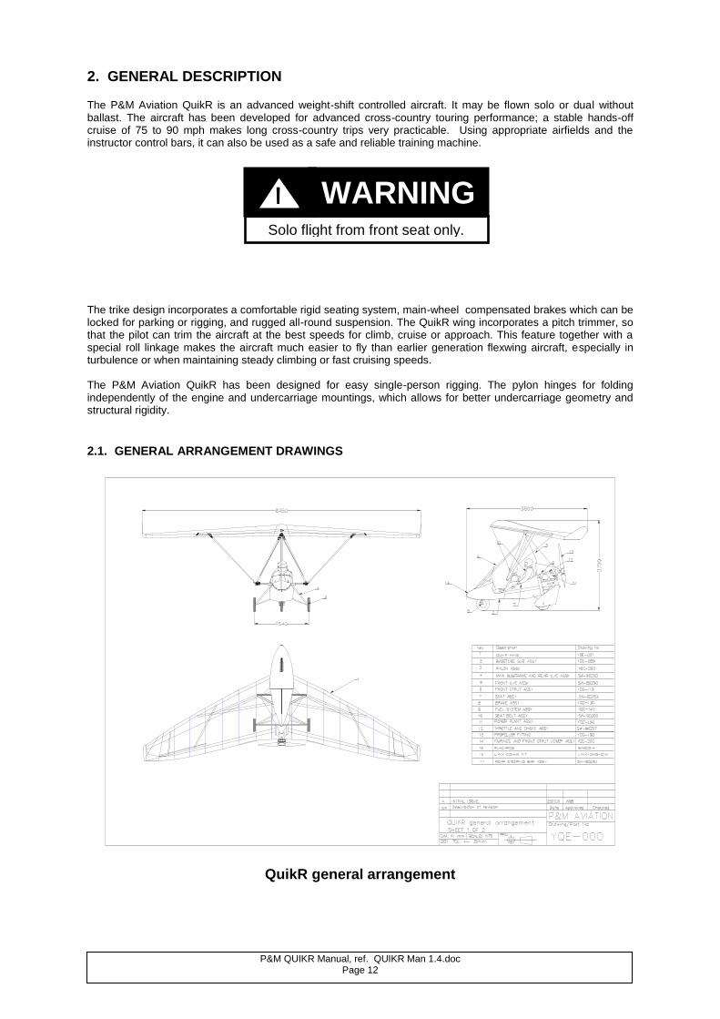
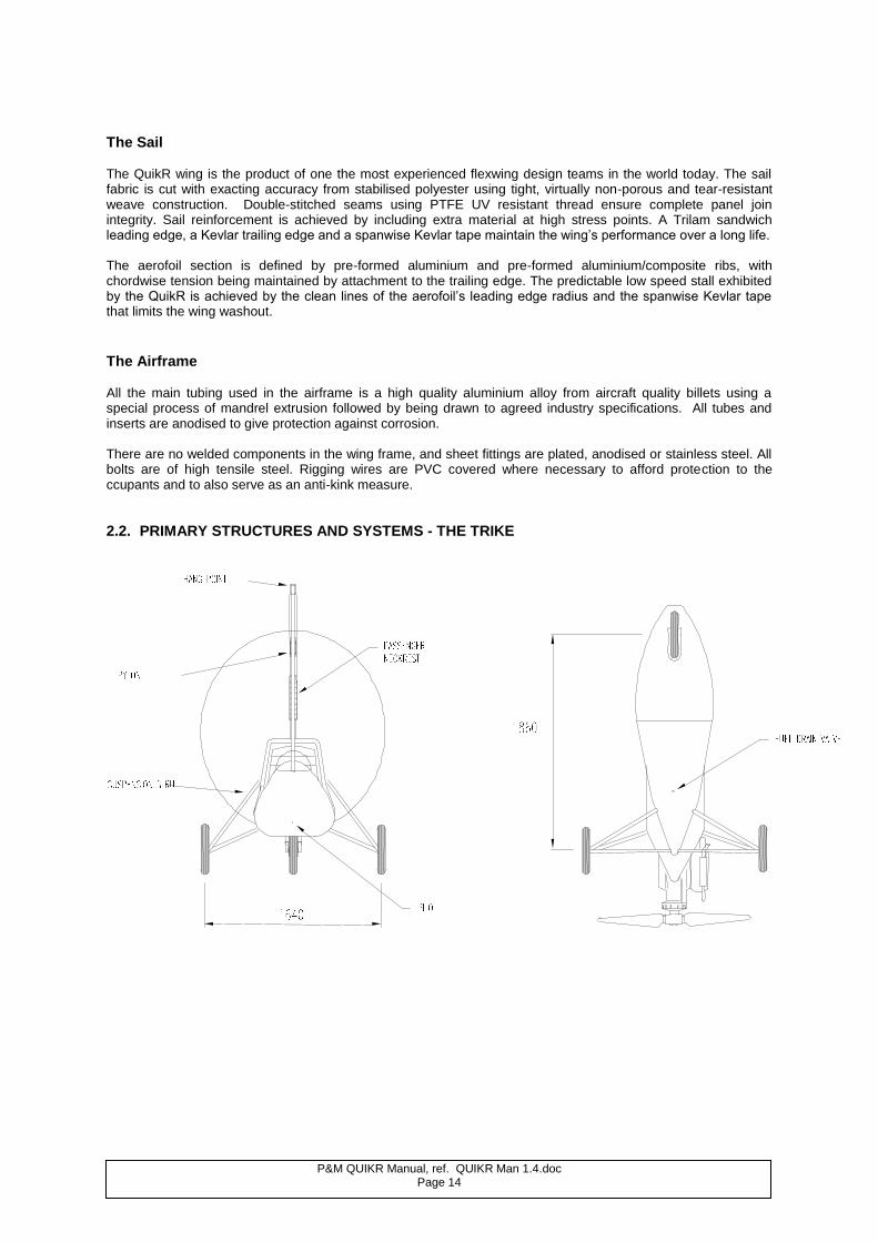
The trike design incorporates a comfortable rigid seating system, main-wheel compensated brakes which can be locked for parking or rigging, and rugged all-round suspension. The QuikR wing incorporates a pitch trimmer, so that the pilot can trim the aircraft at the best speeds for climb, cruise or approach. This feature together with a special roll linkage makes the aircraft much easier to fly than earlier generation flexwing aircraft, especially in turbulence or when maintaining steady climbing or fast cruising speeds. The P&M Aviation QuikR has been designed for easy single-person rigging. The pylon hinges for folding independently of the engine and undercarriage mountings, which allows for better undercarriage geometry and structural rigidity. 2.1. GENERAL ARRANGEMENT DRAWINGS
QuikR general arrangement
Solo flight from front seat only.
WARNING !
P&M QUIKR Manual, ref. QUIKR Man 1.4.doc Page 13
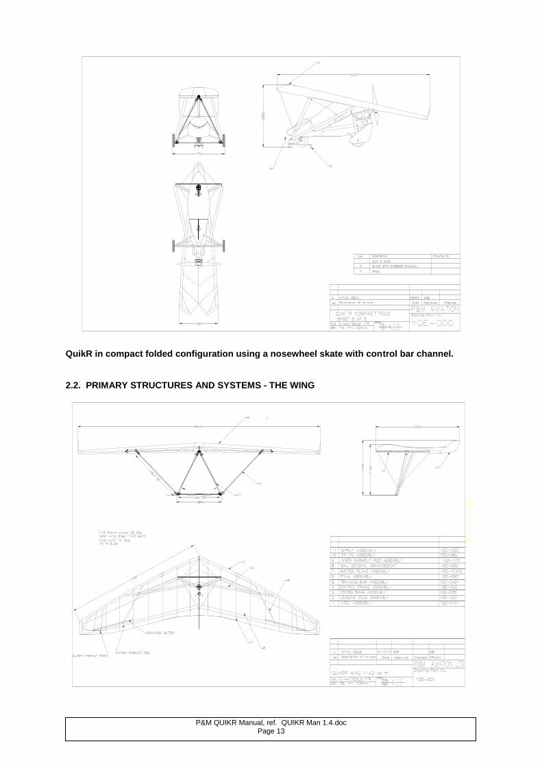
QuikR in compact folded configuration using a nosewheel skate with control bar channel. 2.2. PRIMARY STRUCTURES AND SYSTEMS - THE WING
P&M QUIKR Manual, ref. QUIKR Man 1.4.doc Page 14
The Sail The QuikR wing is the product of one the most experienced flexwing design teams in the world today. The sail fabric is cut with exacting accuracy from stabilised polyester using tight, virtually non-porous and tear-resistant weave construction. Double-stitched seams using PTFE UV resistant thread ensure complete panel join integrity. Sail reinforcement is achieved by including extra material at high stress points. A Trilam sandwich leading edge, a Kevlar trailing edge and a spanwise Kevlar tape maintain the wing’s performance over a long life. The aerofoil section is defined by pre-formed aluminium and pre-formed aluminium/composite ribs, with chordwise tension being maintained by attachment to the trailing edge. The predictable low speed stall exhibited by the QuikR is achieved by the clean lines of the aerofoil’s leading edge radius and the spanwise Kevlar tape that limits the wing washout.
The Airframe All the main tubing used in the airframe is a high quality aluminium alloy from aircraft quality billets using a special process of mandrel extrusion followed by being drawn to agreed industry specifications. All tubes and inserts are anodised to give protection against corrosion. There are no welded components in the wing frame, and sheet fittings are plated, anodised or stainless steel. All bolts are of high tensile steel. Rigging wires are PVC covered where necessary to afford protection to the ccupants and to also serve as an anti-kink measure.
2.2. PRIMARY STRUCTURES AND SYSTEMS - THE TRIKE
P&M QUIKR Manual, ref. QUIKR Man 1.4.doc Page 15
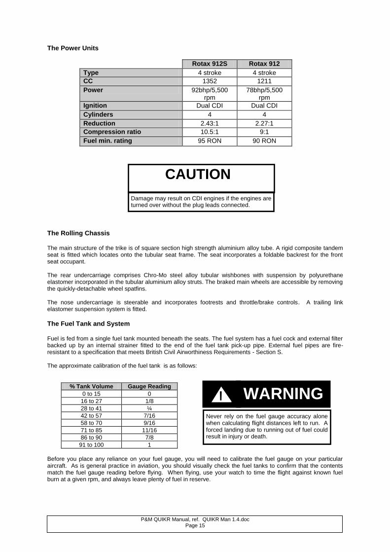
The Power Units
Rotax 912S Rotax 912
Type 4 stroke 4 stroke
CC 1352 1211
Power 92bhp/5,500 rpm
78bhp/5,500 rpm
Ignition Dual CDI Dual CDI
Cylinders 4 4
Reduction 2.43:1 2.27:1
Compression ratio 10.5:1 9:1
Fuel min. rating 95 RON 90 RON
The Rolling Chassis The main structure of the trike is of square section high strength aluminium alloy tube. A rigid composite tandem seat is fitted which locates onto the tubular seat frame. The seat incorporates a foldable backrest for the front seat occupant. The rear undercarriage comprises Chro-Mo steel alloy tubular wishbones with suspension by polyurethane elastomer incorporated in the tubular aluminium alloy struts. The braked main wheels are accessible by removing the quickly-detachable wheel spatfins. The nose undercarriage is steerable and incorporates footrests and throttle/brake controls. A trailing link elastomer suspension system is fitted.
The Fuel Tank and System Fuel is fed from a single fuel tank mounted beneath the seats. The fuel system has a fuel cock and external filter backed up by an internal strainer fitted to the end of the fuel tank pick-up pipe. External fuel pipes are fire-resistant to a specification that meets British Civil Airworthiness Requirements - Section S. The approximate calibration of the fuel tank is as follows:
% Tank Volume Gauge Reading
0 to 15 0
16 to 27 1/8
28 to 41 ¼
42 to 57 7/16
58 to 70 9/16
71 to 85 11/16
86 to 90 7/8
91 to 100 1
Before you place any reliance on your fuel gauge, you will need to calibrate the fuel gauge on your particular aircraft. As is general practice in aviation, you should visually check the fuel tanks to confirm that the contents match the fuel gauge reading before flying. When flying, use your watch to time the flight against known fuel burn at a given rpm, and always leave plenty of fuel in reserve.
CAUTION
Damage may result on CDI engines if the engines are turned over without the plug leads connected.
Never rely on the fuel gauge accuracy alone when calculating flight distances left to run. A forced landing due to running out of fuel could result in injury or death.
WARNING
GG !
P&M QUIKR Manual, ref. QUIKR Man 1.4.doc Page 16
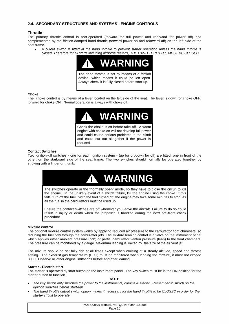
2.4. SECONDARY STRUCTURES AND SYSTEMS - ENGINE CONTROLS Throttle The primary throttle control is foot-operated (forward for full power and rearward for power off) and complemented by the friction-damped hand throttle (forward power on and rearward off) on the left side of the seat frame.
A cutout switch is fitted in the hand throttle to prevent starter operation unless the hand throttle is closed. Therefore for all starts including airborne restarts, THE HAND THROTTLE MUST BE CLOSED.
Choke
The choke control is by means of a lever located on the left side of the seat. The lever is down for choke OFF, forward for choke ON. Normal operation is always with choke off.
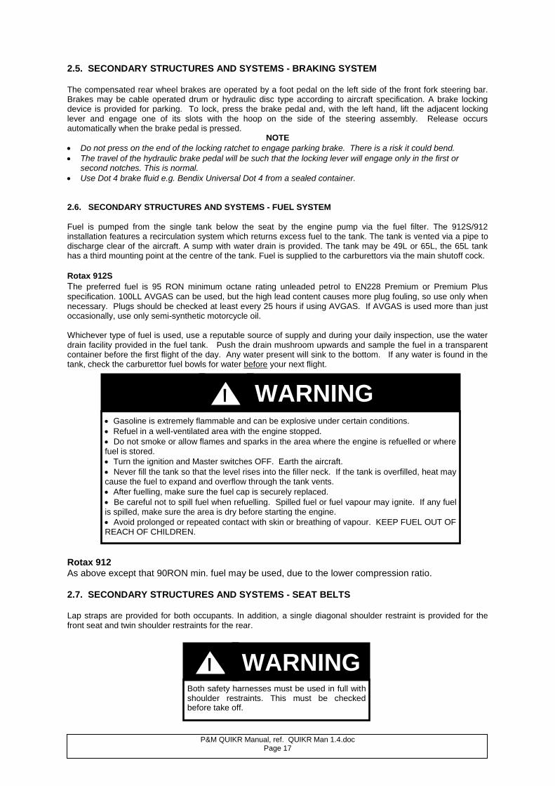
Contact Switches
Two ignition-kill switches - one for each ignition system - (up for on/down for off) are fitted, one in front of the other, on the starboard side of the seat frame. The two switches should normally be operated together by stroking with a finger or thumb.
Mixture control
The optional mixture control system works by applying reduced air pressure to the carburettor float chambers, so reducing the fuel flow through the carburettor jets. The mixture leaning control is a valve on the instrument panel which applies either ambient pressure (rich) or partial carburettor venturi pressure (lean) to the float chambers. The pressure can be monitored by a gauge. Maximum leaning is limited by the size of the air vent jet. The mixture should be set fully rich at all times except when cruising at a steady altitude, speed and throttle setting. The exhaust gas temperature (EGT) must be monitored when leaning the mixture, it must not exceed 800C. Observe all other engine limitations before and after leaning. Starter - Electric start
The starter is operated by start button on the instrument panel. The key switch must be in the ON position for the starter button to function.
NOTE
The key switch only switches the power to the instruments, comms & starter. Remember to switch on the ignition switches before start-up!
The hand throttle cutout switch option makes it necessary for the hand throttle to be CLOSED in order for the starter circuit to operate.
The hand throttle is set by means of a friction device, which means it could be left open. Always check it is fully closed before start-up.
Check the choke is off before take-off. A warm engine with choke on will not develop full power and could cause serious problems in the climb and could cut out altogether if the power is reduced.
The switches operate in the “normally open” mode, so they have to close the circuit to kill the engine. In the unlikely event of a switch failure, kill the engine using the choke. If this fails, turn off the fuel. With the fuel turned off, the engine may take some minutes to stop, as all the fuel in the carburettors must be used up. Ensure the contact switches are off whenever you leave the aircraft. Failure to do so could result in injury or death when the propeller is handled during the next pre-flight check procedure.
WARNING !
WARNING !
WARNING !
P&M QUIKR Manual, ref. QUIKR Man 1.4.doc Page 17
2.5. SECONDARY STRUCTURES AND SYSTEMS - BRAKING SYSTEM The compensated rear wheel brakes are operated by a foot pedal on the left side of the front fork steering bar. Brakes may be cable operated drum or hydraulic disc type according to aircraft specification. A brake locking device is provided for parking. To lock, press the brake pedal and, with the left hand, lift the adjacent locking lever and engage one of its slots with the hoop on the side of the steering assembly. Release occurs automatically when the brake pedal is pressed.
NOTE
Do not press on the end of the locking ratchet to engage parking brake. There is a risk it could bend.
The travel of the hydraulic brake pedal will be such that the locking lever will engage only in the first or second notches. This is normal.
Use Dot 4 brake fluid e.g. Bendix Universal Dot 4 from a sealed container. 2.6. SECONDARY STRUCTURES AND SYSTEMS - FUEL SYSTEM
Fuel is pumped from the single tank below the seat by the engine pump via the fuel filter. The 912S/912 installation features a recirculation system which returns excess fuel to the tank. The tank is vented via a pipe to discharge clear of the aircraft. A sump with water drain is provided. The tank may be 49L or 65L, the 65L tank has a third mounting point at the centre of the tank. Fuel is supplied to the carburettors via the main shutoff cock. Rotax 912S The preferred fuel is 95 RON minimum octane rating unleaded petrol to EN228 Premium or Premium Plus
specification. 100LL AVGAS can be used, but the high lead content causes more plug fouling, so use only when necessary. Plugs should be checked at least every 25 hours if using AVGAS. If AVGAS is used more than just occasionally, use only semi-synthetic motorcycle oil. Whichever type of fuel is used, use a reputable source of supply and during your daily inspection, use the water drain facility provided in the fuel tank. Push the drain mushroom upwards and sample the fuel in a transparent container before the first flight of the day. Any water present will sink to the bottom. If any water is found in the tank, check the carburettor fuel bowls for water before your next flight.
Rotax 912 As above except that 90RON min. fuel may be used, due to the lower compression ratio. 2.7. SECONDARY STRUCTURES AND SYSTEMS - SEAT BELTS Lap straps are provided for both occupants. In addition, a single diagonal shoulder restraint is provided for the front seat and twin shoulder restraints for the rear.
Gasoline is extremely flammable and can be explosive under certain conditions. Refuel in a well-ventilated area with the engine stopped. Do not smoke or allow flames and sparks in the area where the engine is refuelled or where fuel is stored. Turn the ignition and Master switches OFF. Earth the aircraft. Never fill the tank so that the level rises into the filler neck. If the tank is overfilled, heat may cause the fuel to expand and overflow through the tank vents. After fuelling, make sure the fuel cap is securely replaced. Be careful not to spill fuel when refuelling. Spilled fuel or fuel vapour may ignite. If any fuel is spilled, make sure the area is dry before starting the engine. Avoid prolonged or repeated contact with skin or breathing of vapour. KEEP FUEL OUT OF REACH OF CHILDREN.
Both safety harnesses must be used in full with shoulder restraints. This must be checked before take off.
WARNING !
WARNING !
P&M QUIKR Manual, ref. QUIKR Man 1.4.doc Page 18
2.8. SECONDARY STRUCTURES AND SYSTEMS – COCKPIT, FAIRINGS AND SCREEN All fairings are made of lightweight composite materials and serve the dual functions of giving the pilot a degree of weather protection as well as improving the aerodynamics of the aircraft. The QuikR spat fins are necessary to provide aerodynamic yaw stability and must always be fitted. The polycarbonate screen with deflectors protects the pilot from the slipstream, it must be kept clear using a clean cloth, soap and plenty of water. A screen extension is optionally available which attaches with Dzus fasteners to give improved protection for tall pilots and for rear seat occupants.
The screen must be removed when folding the pylon for rigging / de rigging.
Any further modifications which add side area to the front of the pod will adversely affect high speed yaw stability and are not recommended without extensive flight testing.
2.9. SECONDARY STRUCTURES AND SYSTEMS - ELECTRICAL SYSTEM The aircraft is fitted with two standard wiring systems; one for transmission of electrical power derived from the engine alternator and the other for sensor signals to be used in instrumentation. Two independent sets of cables to the two separate ignition switches are provided. The power available from the alternator is a function of engine speed and the electrical load.
Connection to the wiring is via crimp connections in rubber connector housings and, in the case of the power wiring loom, via spade terminals to a multiway fuseholder at the front of the aircraft. All models are fitted with a regulator, which charges the battery where fitted. Electric start models have a solenoid for transmitting current to the starter motor.
2.10. SECONDARY STRUCTURES AND SYSTEMS - CARBURETTOR HEAT
Evaporation of the fuel at low pressure in the intake tract can lead to carburettor icing in humid conditions
particularly between +10 and -5C ambient temperature. Icing is generally more prevalent at part throttle settings. Symptoms include rough running, power loss and sometimes throttle sticking open. Throttle sticking may also occur through cable freezing if not correctly maintained - see Maintenance Section. Rotax 912S/912 Carburettor Heat System
A carburettor body and butterfly warming system supplied with heat from the coolant is installed, which is always ON, as there is no effect on engine performance. The radiator cover should be adjusted to obtain at least 80C coolant temperature for the system to work effectively. In severe icing conditions the occasional hiccup as ice is melted and dislodged, is normal. In such conditions it is advisable to warm the engine periodically on long descents.
2.11. SECONDARY STRUCTURES AND SYSTEMS - RADIATOR COVERS 912S/912 Oil Radiator Jacket In accordance with P&M Aviation Service Bulletin No: 0094, in which it was noted that it was desirable for the
oil temperature on aircraft equipped with the Rotax four stroke engines to reach 100C at least once per flight, P&M Aviation now supply a neoprene jacket which may be fitted to the oil radiator and when the aircraft is operated in cool ambient temperature. The purpose of this jacket is:
Take care not to disturb the wiring under the pod with your feet. Do not store things under the seat that can disturb connections
WARNING !
P&M QUIKR Manual, ref. QUIKR Man 1.4.doc Page 19
1. To make it easier to reach 100C in normal use, in order to minimise the risk of humidity building up in the oil system.
2. To speed up the warm-up procedure.
Note! If your aircraft regularly reaches 100C in normal operations, there is no need to fit the cover. Usage
The oil temperature on the 912S/912 depends on the use to which it is put. Extended periods at high RPM in hot
climates will result in temperatures of 100+C, whereas at a typical cruise of 4000rpm in an ambient temperature
of 23C or less, 75-85 is the normal oil temperature. Whether to use the jacket with 100% or 50% coverage, or indeed at all, becomes a function of how the engine is used and in what ambient temperatures. The responsibility for ensuring that the oil temperature remains within the correct limits is therefore the pilot’s. Regular
in-flight checks should be made to ensure that the oil temperature remains within the desired range of 85-100C and that the following limitations are respected:
1. Lower oil limit: 50C
2. Upper oil limit 912 engine: 140C 912S engine: 130C Adjustment
In the event that 120C is reached in a typical climb to 2000’ or 600m, it is probable that the jacket is covering too much of the radiator for the prevailing conditions. Make a precautionary landing and adjust/remove as necessary. To adjust from 100% to 50% coverage, simply pull the bottom of the cover up to the top. The following are typical coverage settings in normal usage:
AMBIENT TEMPERATURE RADIATOR COVERAGE
Up to 23C 100%
24-32C 50%
33C+ No coverage - remove jacket Inspection
Check the security of the installation of the jacket as part of your daily inspection, and carefully inspect the jacket for wear or damage every 50 hours.
2.12 Electric trimmer. The wing is provided with a small bracket on the wing keel. An electric winch with limit switches and position sensor is mounted at the bottom of the pylon. The winch is operated by a spring-return switch on the throttle box and the trim position is displayed by LED bar graph on the instrument panel. The winch pulls on a bungee inside the pylon fairing which pulls a cord connected via a pulley to the wing keel bracket. The wing is designed to trim fully fast with the trimmer slack. As the trimmer is set to slow, the bungee pulls the rear of the keel downwards, increasing the angle of attack and slowing the trim speed. Normal operation
The basic operation of the trimmer is to set the desired attitude and adjust the power setting so that the aircraft is in a steady state, and then adjust the trimmer till the bar force disappears. It is not good practice to fight the trimmer by pulling the bar in whilst selecting slow trim. The trimmer takes approximately 18 seconds to run through the whole range. In the cruise, there may be a delay of a few seconds when selecting nose-up trim as the trimmer takes up the slack. Note that the takeoff trim placard is set at approximately 65mph, to avoid too much pitch-up on the initial climb. For landing approach, trim at 55-60 mph solo, 60-65 mph dual. Abnormal operation
The trim motor only runs when the pilot holds the trim switch, it will stop as soon as it is released. It can also be stopped by pulling out the 5A circuit breaker or by turning off the main master switch.
The trim motor 5Amp circuit breaker should not trip under any normal operating condition. It may trip if the pilot pulls the bar all the way back whilst selecting full nose up trim; this practice is not recommended as it puts unnecessary load on the system. In this case it is permissible to reset the C.B. after 2 minutes. The C.B. will also trip if the trim motor should run past the normal limit microswitch and the motor is not stopped by the pilot, in which case the bungee will eventually be stopped at the top of the engine mount frame and the trim speed will be very slow, 45-50mph. With correct inspection and maintenance, trim cord or bungee failure is unlikely. If it happens the aircraft will go to full fast trim. In the case of main electrical system failure, the trim will stay where it is. In any case, fly the aircraft at the normal approach and landing speeds, accepting the out-of-trim force.

P&M QUIKR Manual, ref. QUIKR Man 1.4.doc Page 20
NOTE
The aircraft should be left with the trimmer slack (fast) to prolong the life of the system.
With correct maintenance, failure is unlikely. However It is advisable to practice landing at both extremes of trim occasionally.
Never take off with a faulty trim system. Always check trim operation and flight controls before takeoff.
WARNING !
P&M QUIKR Manual, ref. QUIKR Man 1.4.doc Page 21
3. GENERAL INFORMATION
3.1. EMPTY WEIGHT Typical empty weights for the P&M Aviation QuikR are as follows:
Rotax 912 912 S
218 220kg
480 484lbs
Following modification, repair or at any time required by the CAA or other Airworthiness Authority, the aeroplane must be weighed so that the composition of useful load can be determined. The aeroplane must be dry, clean and in calm conditions for accurate weighing. The empty weight must be recorded below and on the main cockpit placard after each weighing. The aeroplane empty weight must under no circumstances exceed 265kg (583lbs). The P&M Aviation QuikR, registration mark......................, engine type..............................., has been weighed empty, including full oil, electrolyte and unusable fuel:
WEIGHT MODIFICATION STATE DATE
3.2 FUEL LOADS – 65L tank
FUEL LOADS
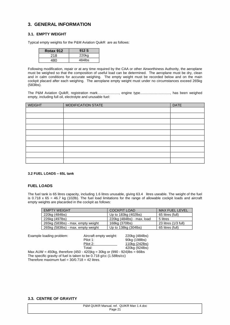
The fuel tank is 65 litres capacity, including 1.6 litres unusable, giving 63.4 litres useable. The weight of the fuel is 0.718 x 65 = 46.7 kg (102lb). The fuel load limitations for the range of allowable cockpit loads and aircraft empty weights are placarded in the cockpit as follows:
EMPTY WEIGHT COCKPIT LOAD MAX FUEL LEVEL
220kg (484lbs) Up to 183kg (402lbs) 65 litres (full)
226kg (497lbs) 220kg (484lbs) - max. load 5 litres
265kg (583lbs) - max. empty weight 168kg (370lbs) 23 litres (1/3 full)
265kg (583lbs) - max. empty weight Up to 138kg (304lbs) 65 litres (full)
Example loading problem: Aircraft empty weight: 220kg (484lbs) Pilot 1: 90kg (198lbs) Pilot 2: 110kg (242lbs) Total: 420kg (924lbs) Max AUW = 450kg, therefore (450 - 420)kg = 30kg or (990 - 924)lbs = 66lbs The specific gravity of fuel is taken to be 0.718 g/cc (1.58lbs/cc) Therefore maximum fuel = 30/0.718 = 42 litres.
3.3. CENTRE OF GRAVITY
P&M QUIKR Manual, ref. QUIKR Man 1.4.doc Page 22
Trike
The centre of gravity (CG) of the trike is not very critical - it only affects the range of pitch control movement, not the trim speed. The CG of both the rear seat occupant and the fuel are as close as possible to the hang point with the trike in the suspended attitude, so the suspended attitude is little affected with load variation. Solo flight is from the front seat only.
Wing
The CG of the wing is critical. Due to the materials used and the quality control in manufacture, the CG of the QuikR wing does not vary significantly in production. Items should not be attached to the wing which significantly change the CG. The hang point position on the wing keel must not be moved from the designed and tested position.
3.4. AIRCRAFT DIMENSIONS
Wing Data Wing Span: 27ft 9in 8.45 m
Sail Area: 123 sq ft. 11.43 sq. m. Aspect Ratio: 6.24
Trike Data Length (erect): 111.0 ins 290.0 cm
Length (fold down): 114.0 ins 290.0 cm Width: 72.0 ins 83.0 cm Track: 65.0 ins 165.0 cm Height (erect): 98.0 ins 230.0 cm Height (fold down): 61.0 ins 140.0 cm
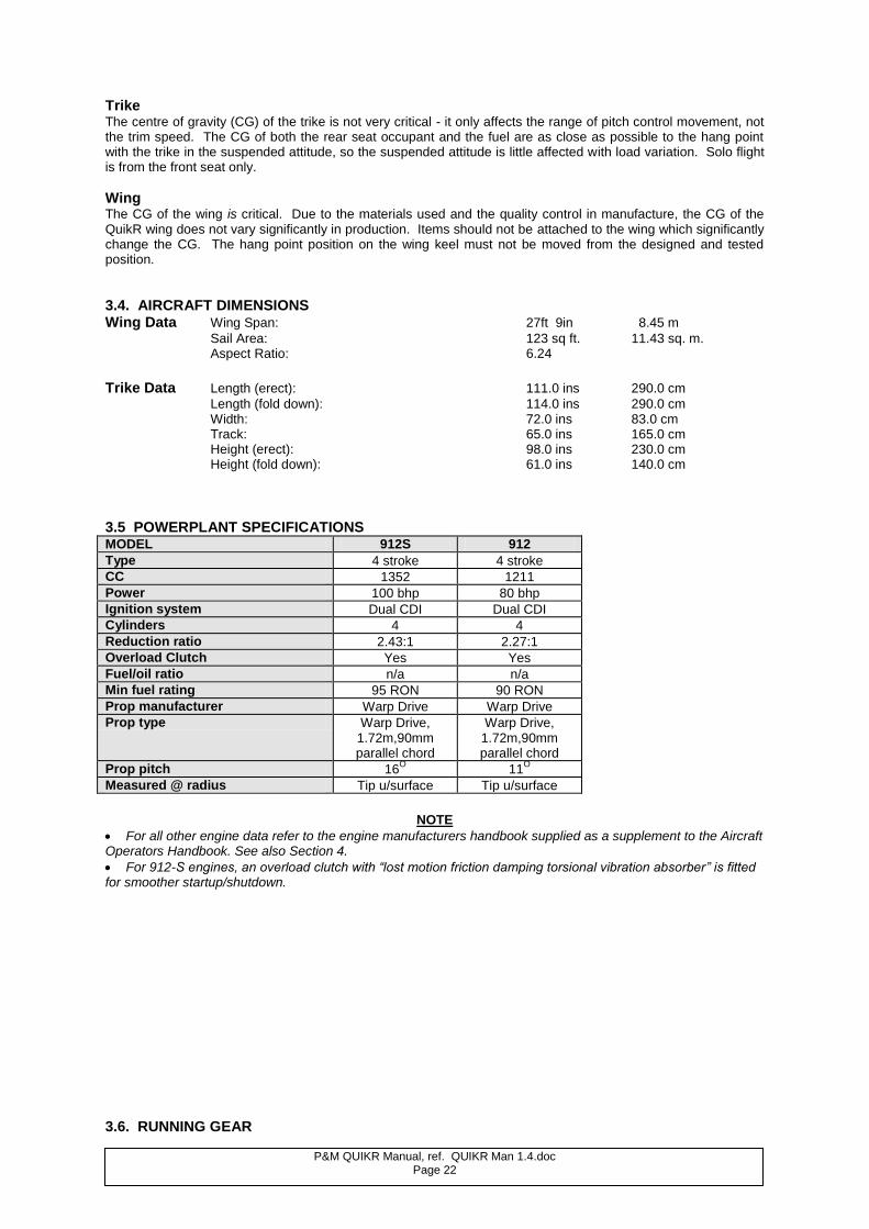
3.5 POWERPLANT SPECIFICATIONS MODEL 912S 912
Type 4 stroke 4 stroke
CC 1352 1211
Power 100 bhp 80 bhp
Ignition system Dual CDI Dual CDI
Cylinders 4 4
Reduction ratio 2.43:1 2.27:1
Overload Clutch Yes Yes
Fuel/oil ratio n/a n/a
Min fuel rating 95 RON 90 RON
Prop manufacturer Warp Drive Warp Drive
Prop type Warp Drive, 1.72m,90mm parallel chord
Warp Drive, 1.72m,90mm parallel chord
Prop pitch 16O
11O
Measured @ radius Tip u/surface Tip u/surface
NOTE
For all other engine data refer to the engine manufacturers handbook supplied as a supplement to the Aircraft Operators Handbook. See also Section 4.
For 912-S engines, an overload clutch with “lost motion friction damping torsional vibration absorber” is fitted for smoother startup/shutdown.
3.6. RUNNING GEAR
P&M QUIKR Manual, ref. QUIKR Man 1.4.doc Page 23
Tyre Pressures - front and rear 22.0 psi 1.5 bar
3.7. PLACARDS, DECALS AND LOCATIONS
UK specification. Title Location
Flight Limitations: On basetube or left hand wing upright. Engine Limitations: On panel or left hand wing upright Aircraft Weights: On basetube or panel Map Box Weight Limitations: On map box Fuel Type, Capacity and Mix Ratio: On rear suspension leg Fuel Cock On/Off Positions: On seat. Ignition Switch On/Off Positions: On ignition switch bracket Propeller Pitch Setting: On airbox or radiator Hand Throttle: On throttle unit. Wiring Loom Disconnection Warning: On airbox or carb covers Trimmer Setting: On trim switch ( electric trim) On trim display (electric trim) Tip Turn Adjusters: On leading edge tube tips Latch Locking: On seat next to latch Oil Type and Quantity: On oil cap Loose Hair or Clothing: On rear of seat Propeller Pitch: On oil cooler Fuel Load Limitations: In the cockpit
Additional for US specification Propeller Tip Covers: On each propeller blade
Nose Cone: On sail under nose cone Hang Bracket Warning: On hang bracket Exhaust Hot: On top of exhaust brackets Folded Pylon: On pylon or pylon fairing Front Strut Pins: On front strut by pins Exhaust Stubs Hot: On 912 cylinder head Operator’s Manual/Aerobatics Warning: On panel Rotating Parts: On plate on top of engine
Roll and Pitch Angles: On port upright Tensioner Cable: In fin pocket Hang Bolt Warning: On hang bracket Propeller Arc Warning: On lower pylon fairing Radiator Cap Warning: On reservoir under radiator cap Propeller Tip Covers: On each propeller blade
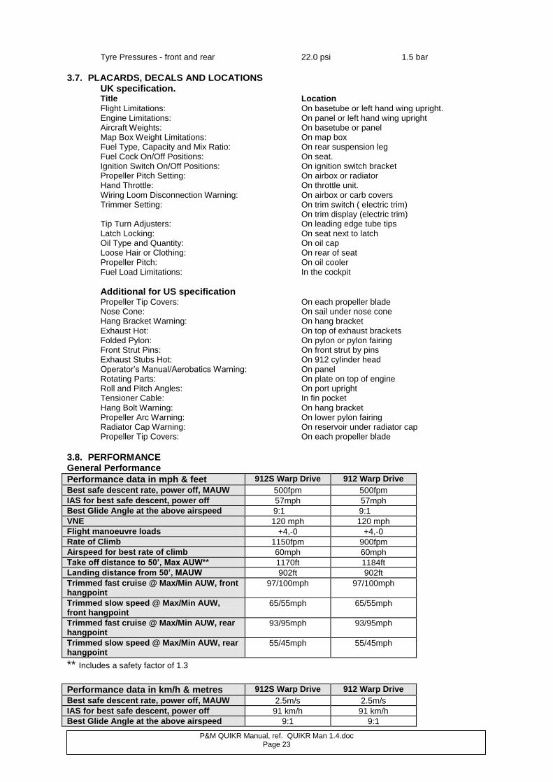
3.8. PERFORMANCE General Performance
Performance data in mph & feet 912S Warp Drive 912 Warp Drive
Best safe descent rate, power off, MAUW 500fpm 500fpm
IAS for best safe descent, power off 57mph 57mph
Best Glide Angle at the above airspeed 9:1 9:1
VNE 120 mph 120 mph
Flight manoeuvre loads +4,-0 +4,-0
Rate of Climb 1150fpm 900fpm
Airspeed for best rate of climb 60mph 60mph
Take off distance to 50’, Max AUW** 1170ft 1184ft
Landing distance from 50’, MAUW 902ft 902ft
Trimmed fast cruise @ Max/Min AUW, front hangpoint
97/100mph 97/100mph
Trimmed slow speed @ Max/Min AUW, front hangpoint
65/55mph 65/55mph
Trimmed fast cruise @ Max/Min AUW, rear hangpoint
93/95mph 93/95mph
Trimmed slow speed @ Max/Min AUW, rear hangpoint
55/45mph 55/45mph
** Includes a safety factor of 1.3 Performance data in km/h & metres 912S Warp Drive 912 Warp Drive
Best safe descent rate, power off, MAUW 2.5m/s 2.5m/s
IAS for best safe descent, power off 91 km/h 91 km/h
Best Glide Angle at the above airspeed 9:1 9:1
P&M QUIKR Manual, ref. QUIKR Man 1.4.doc Page 24
VNE 192 km/h 192 km/h
Flight manoeuvre loads +4g/-0g +4g/-0g
Rate of Climb 5.8 m/s 4.57 m/s
Airspeed for best rate of climb 96km/h 96km/h
Take off distance to 15m, Max AUW** 357 m 361 m
Landing distance from 15m, MAUW 275 m 275 m
Trimmed fast cruise @ Max/Min AUW, front hangpoint
155/160 km/h 155/160 km/h
Trimmed slow speed @ Max/Min AUW, front hangpoint
104/88 km/h 104/88 km/h
Trimmed fast cruise @ Max/Min AUW, rear hangpoint
149/152 km/h 149/152 km/h
Trimmed slow speed @ Max/Min AUW, rear hangpoint
88/72 km/h 88/72 km/h
** includes a safety factor of 1.3
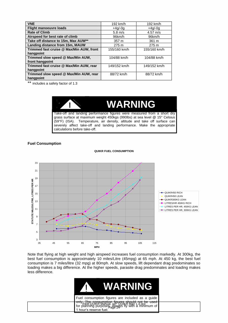
Fuel Consumption
QUIKR FUEL CONSUMPTION
3
5
7
9
11
13
15
17
19
21
23
35 45 55 65 75 85 95 105 115
MPH
ST
AT
UT
E M
ILE
S/L
ITR
E, L
ITR
ES
PE
R H
R
QUIKR450 RICH
QUIKR450 LEAN
QUIKR300KG LEAN
LITRES/HR 450KG RICH
LITRES PER HR, 450KG LEAN
LITRES PER HR, 300KG LEAN
Note that flying at high weight and high airspeed increases fuel consumption markedly. At 300kg, the best fuel consumption is approximately 10 miles/Litre (45mpg) at 65 mph. At 450 kg, the best fuel consumption is 7 miles/litre (32 mpg) at 80mph. At slow speeds, lift dependant drag predominates so loading makes a big difference. At the higher speeds, parasite drag predominates and loading makes less difference.
Take-off and landing performance figures were measured from a short dry grass surface at maximum weight 450kgs (990lbs) at sea level @ 15° Celsius (59°F) (ISA). Temperature, air density, altitude and take off surface can severely affect take-off and landing performance. Make the appropriate calculations before take-off.
Fuel consumption figures are included as a guide only. The consumption figures should not be used for planning purposes. Always fly with a minimum of 1 hour’s reserve fuel.
WARNING !
WARNING !
P&M QUIKR Manual, ref. QUIKR Man 1.4.doc Page 25
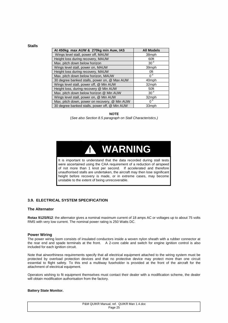
Stalls
At 450kg max AUW & 270kg min Auw, IAS All Models
Wings level stall, power off, MAUW 38mph
Height loss during recovery, MAUW 60ft
Max. pitch down below horizon 30 o
Wings level stall, power on, MAUW 39mph
Height loss during recovery, MAUW 0ft
Max. pitch down below horizon, MAUW 0 o
30 degree banked stalls, power on, @ Max AUW 40mph
Wings level stall, power off, @ Min AUW 32mph
Height loss, during recovery @ Min AUW 50ft
Max. pitch down below horizon @ Min AUW 30 o
Wings level stall, power on, @ Min AUW 32mph
Max. pitch down, power on recovery, @ Min AUW 0 o
30 degree banked stalls, power off, @ Min AUW 33mph
NOTE
(See also Section 8.5 paragraph on Stall Characteristics.)
3.9. ELECTRICAL SYSTEM SPECIFICATION The Alternator Rotax 912S/912: the alternator gives a nominal maximum current of 18 amps AC or voltages up to about 75 volts
RMS with very low current. The nominal power rating is 250 Watts DC.
Power Wiring The power wiring loom consists of insulated conductors inside a woven nylon sheath with a rubber connector at the rear end and spade terminals at the front. A 2-core cable and switch for engine ignition control is also included for each ignition circuit. Note that airworthiness requirements specify that all electrical equipment attached to the wiring system must be protected by overload protection devices and that no protective device may protect more than one circuit essential to flight safety. To this end a multiway fuseholder is provided at the front of the aircraft for the attachment of electrical equipment. Operators wishing to fit equipment themselves must contact their dealer with a modification scheme, the dealer will obtain modification authorisation from the factory. Battery State Monitor.
It is important to understand that the data recorded during stall tests were ascertained using the CAA requirement of a reduction of airspeed of not more than 1 knot per second. If accelerated and therefore unauthorised stalls are undertaken, the aircraft may then lose significant height before recovery is made, or in extreme cases, may become unstable to the extent of being unrecoverable.
WARNING !
P&M QUIKR Manual, ref. QUIKR Man 1.4.doc Page 26
A single LED Battery State Monitor (BSM) may be fitted. When power is switched on, it conducts a brief check sequence. It indicates as follows: No power (0-5v) Neutral GREY Low volts ( 6- 11.5v) Slow flashing RED Good battery off charge (11.5-12.5v) Steady ORANGE Battery on charge (12.5-14.5v) Steady GREEN Over voltage (14.5v +) Fast flashing RED Any fault condition should be investigated before further flight. It may be wise to turn the master switch off.
Sensor Wiring The sensor wiring system comprises a multicore cable intended for transmission of signals not involving significant power levels. No items requiring significant power with an alternating component should have their supply lines attached to this cable as electrical interference with sensor signals may occur.
Unauthorised modifications, including the fitting of optional electrical equipment, must not be carried out under any circumstances without official modification authorisation issued by the factory.
CAUTION
When the aircraft is stored for an extended period of time, remove the battery and charge it fully. Then store it in a warm dry place. Never leave the battery discharged.
The battery gives off explosive gases; keep sparks, flames and cigarettes away. Provide adequate ventilation when charging or using batteries in an enclosed space. The battery contains sulphuric acid (electrolyte). Contact with skin or eyes may cause severe burns, wear protective clothing and a face shield.
If electrolyte gets on your skin, flush with water.
If electrolyte gets in your eyes, flush with water for at least 15 minutes and call a physician immediately.
Electrolyte is poisonous, if swallowed, drink large quantities of water, follow with milk of magnesia and call a physician immediately.
WARNING !
WARNING !
P&M QUIKR Manual, ref. QUIKR Man 1.4.doc Page 27
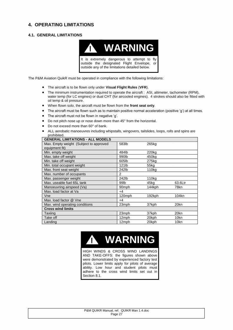
4. OPERATING LIMITATIONS 4.1. GENERAL LIMITATIONS
The P&M Aviation QuikR must be operated in compliance with the following limitations:
The aircraft is to be flown only under Visual Flight Rules (VFR).
The minimum instrumentation required to operate the aircraft : ASI, altimeter, tachometer (RPM), water temp (for LC engines) or dual CHT (for aircooled engines). 4 strokes should also be fitted with oil temp & oil pressure.
When flown solo, the aircraft must be flown from the front seat only.
The aircraft must be flown such as to maintain positive normal acceleration (positive ‘g’) at all times.
The aircraft must not be flown in negative ‘g’.
Do not pitch nose up or nose down more than 45° from the horizontal.
Do not exceed more than 60° of bank.
ALL aerobatic manoeuvres including whipstalls, wingovers, tailslides, loops, rolls and spins are prohibited.
GENERAL LIMITATIONS - ALL MODELS
Max. Empty weight (Subject to approved equipment fit)
583lb 265kg
Min. empty weight 484lb 220kg
Max. take off weight 990lb 450kg
Min. take off weight 605lb 275kg
Min. total occupant weight 121lb 55kg
Max. front seat weight 242lb 110kg
Max. number of occupants 2
Max. passenger weight 242lb 110kg
Max. useable fuel 65L tank 99lb 45kg 63.6Ltr
Manoeuvring airspeed (Va) 90mph 144kph 78kn
Max. load factor at Va +4
Vne 120mph 192kph 104kn
Max. load factor @ Vne +4
Max. wind operating conditions 23mph 37kph 20kn
Cross wind limits
Taxiing 23mph 37kph 20kn
Take off 12mph 20kph 10kn
Landing 12mph 20kph 10kn
It is extremely dangerous to attempt to fly outside the designated Flight Envelope, or outside any of the limitations detailed below.
WARNING !
HIGH WINDS & CROSS WIND LANDINGS AND TAKE-OFFS: the figures shown above were demonstrated by experienced factory test pilots. Lower limits apply for pilots of average ability. Low hour and student pilots must adhere to the cross wind limits set out in Section 8.1.
WARNING !
P&M QUIKR Manual, ref. QUIKR Man 1.4.doc Page 28
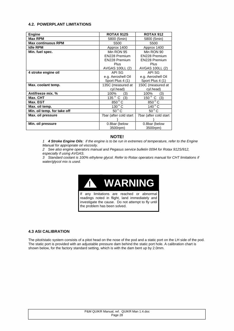
4.2. POWERPLANT LIMITATIONS
Engine ROTAX 912S ROTAX 912
Max RPM 5800 (5min) 5800 (5min)
Max continuous RPM 5500 5500
Idle RPM Approx 1400 Approx 1400
Min. fuel spec. Min RON 95 EN228 Premium EN228 Premium
Plus AVGAS 100LL (2)
Min RON 90 EN228 Premium EN228 Premium
Plus AVGAS 100LL (2)
4 stroke engine oil API SG e.g. Aeroshell Oil Sport Plus 4 (1)
API SG e.g. Aeroshell Oil Sport Plus 4 (1)
Max. coolant temp. 135C (measured at cyl.head)
150C (measured at cyl.head)
Antifreeze mix. % 100% (3) 100% (3)
Max. CHT 135 o C (3) 150
o C (3)
Max. EGT 850 o
C 850 o
C
Max. oil temp. 130 o
C 140 o
C
Min. oil temp. for take off 50 o
C 50 o
C
Max. oil pressure 7bar (after cold start )
7bar (after cold start )
Min. oil pressure 0.8bar (below 3500rpm)
0.8bar (below 3500rpm)
NOTE! 1 4 Stroke Engine Oils: if the engine is to be run in extremes of temperature, refer to the Engine Manual for appropriate oil viscosity. 2 See also engine operators manual and Pegasus service bulletin 0094 for Rotax 912S/912, especially if using AVGAS. 3 Standard coolant is 100% ethylene glycol. Refer to Rotax operators manual for CHT limitations if water/glycol mix is used.
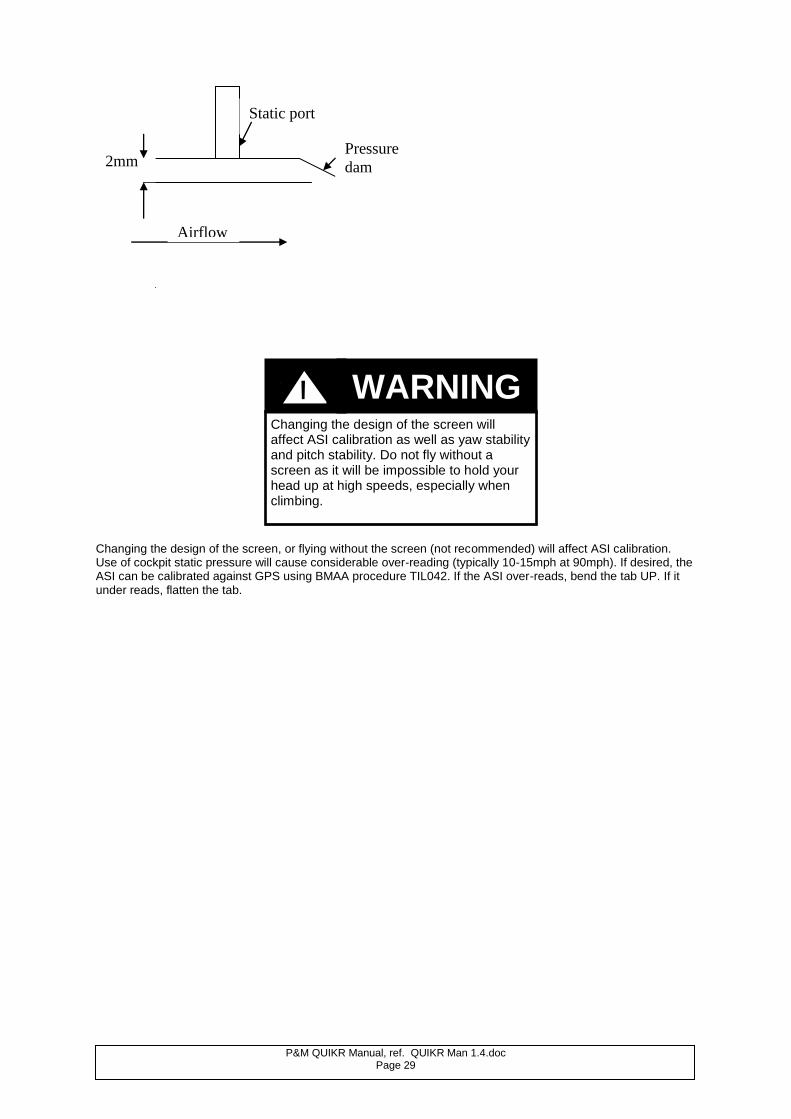
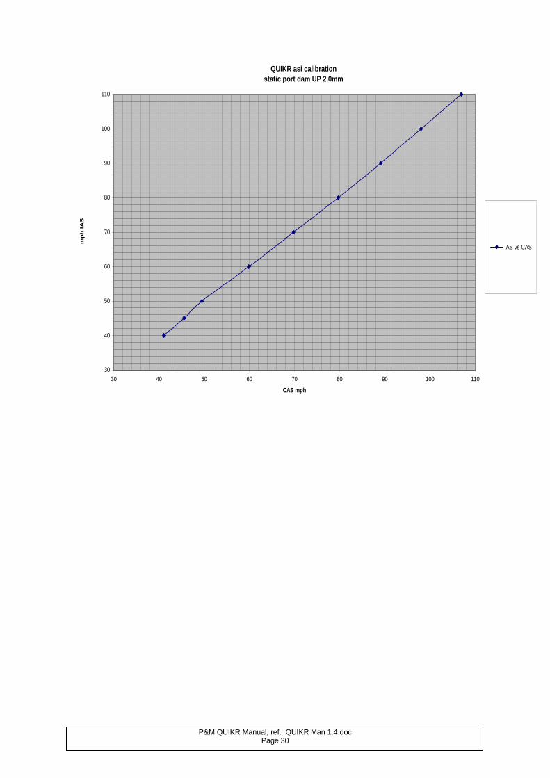
4.3 ASI CALIBRATION The pitot/static system consists of a pitot head on the nose of the pod and a static port on the LH side of the pod. The static port is provided with an adjustable pressure dam behind the static port hole. A calibration chart is shown below, for the factory standard setting, which is with the dam bent up by 2.0mm.
If any limitations are reached or abnormal readings noted in flight, land immediately and investigate the cause. Do not attempt to fly until the problem has been solved.
WARNING !
P&M QUIKR Manual, ref. QUIKR Man 1.4.doc Page 29
Changing the design of the screen, or flying without the screen (not recommended) will affect ASI calibration. Use of cockpit static pressure will cause considerable over-reading (typically 10-15mph at 90mph). If desired, the ASI can be calibrated against GPS using BMAA procedure TIL042. If the ASI over-reads, bend the tab UP. If it under reads, flatten the tab.
2mm
Airflow
Pressure
dam
Static port
Changing the design of the screen will affect ASI calibration as well as yaw stability and pitch stability. Do not fly without a screen as it will be impossible to hold your head up at high speeds, especially when climbing.
WARNING !
P&M QUIKR Manual, ref. QUIKR Man 1.4.doc Page 30
QUIKR asi calibration
static port dam UP 2.0mm
30
40
50
60
70
80
90
100
110
30 40 50 60 70 80 90 100 110
CAS mph
mp
h I
AS
IAS vs CAS
P&M QUIKR Manual, ref. QUIKR Man 1.4.doc Page 31
5. RIGGING THE AIRCRAFT
5.1. GENERAL
As you rig your aircraft, you should always be meticulous in your inspection of each component. This is the best time to see potential faults or problem areas which may be missed when the aircraft is fully rigged. Never allow yourself to be distracted during assembly of your aircraft and always rig to a repeatable sequence. Do not rely on the pre-flight check to find faults, but look carefully at all aspects of your aircraft as you put it together. Great care should be taken with wings which are left fully rigged, for checks cannot be omitted on that account, and the full inspection procedures should be followed. The design brief for the P&M QuikR called for easy inspectability, so those components not open to view may be reached from zipped inspection panels. (See airframe parts drawings). Special attention should be paid to the following:
1. The symmetry of the wing. 2. All tubes straight, undented and without cracks. 3. All cables unkinked, unfrayed and with undamaged sleeves. 4. All nuts and bolts secure and locked appropriately. 5. All quick-release fittings secure, safety pin on crossboom restraint. 6. Hang-point and hang-bolt undamaged and secure. Hang point roll bearing bolts secure. 7. Control frame uprights straight, end fittings and fasteners secure. 8. All sail seams intact, with no frayed stitching. 9. No tears in the sail. 10. Batten elastics not frayed, knots secure, and fitted correctly. 11. Double check 7. and 8. in sail areas of high stress. Particular areas of high stress are:
Both tip fabric areas including tip fastening. Both leading edge upper surfaces. Undersurface at the joint seam with the leading edge, towards the nose. Around the securing screws at the nose of the wing (check that securing screws and grommets have not become detached from the sail). The trailing edge stitching, grommets and shock cords. Keel pocket, particularly at the point of attachment to the upper surface. The point of attachment in the root area of the undersurface to the upper surface. Strut entry and exit points. The area above the crossboom centre ball.
12. Sail tip adjuster settings correctly aligned and secure. 13. Ribs undistorted, undented, in good condition and profile as supplied batten plan, bungees tight and
doubled on all top surface batten ends. 14. Lift strut end fittings secure and undamaged. 15. Lift strut bolts/wingnuts secure. 16. Lift strut strap to crossboom – check for distortion/cracking. 17. Inner and outer washout rods both resting under the carbon spanwise sail batten. 18. Carbon battens including spanwise battens not broken. 19. Trim cord connected, not frayed. 20. Lower rear rigging rocker assembly and cables secure, nose catch secure. 21. Nose cone fitted and secure.
Rigging the aircraft is a simple operation when carried out correctly. However, if you do not use the correct procedures or techniques this may result in an incorrectly rigged aircraft that could cause injury or death if operated in this condition.
WARNING !
P&M QUIKR Manual, ref. QUIKR Man 1.4.doc Page 32
5.2. WING RIGGING
1. Select a clean, dry area and lay the wing down, opening the zip to reveal the control frame and
underside of the wing. Remove the sail ties and padding. 2. Open out the control frame and attach the base bar to the corner joints. Inspect the basebar holes for
damage.
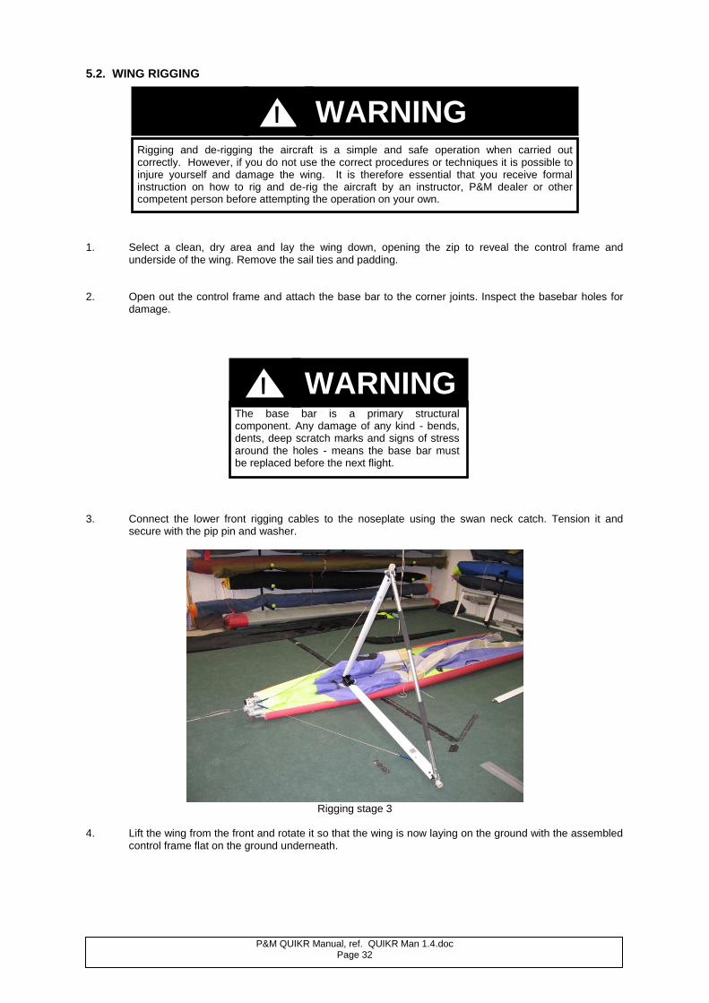
3. Connect the lower front rigging cables to the noseplate using the swan neck catch. Tension it and
secure with the pip pin and washer.
Rigging stage 3
4. Lift the wing from the front and rotate it so that the wing is now laying on the ground with the assembled
control frame flat on the ground underneath.
The base bar is a primary structural component. Any damage of any kind - bends, dents, deep scratch marks and signs of stress around the holes - means the base bar must be replaced before the next flight.
Rigging and de-rigging the aircraft is a simple and safe operation when carried out correctly. However, if you do not use the correct procedures or techniques it is possible to injure yourself and damage the wing. It is therefore essential that you receive formal instruction on how to rig and de-rig the aircraft by an instructor, P&M dealer or other competent person before attempting the operation on your own.
WARNING !
WARNING !
P&M QUIKR Manual, ref. QUIKR Man 1.4.doc Page 33
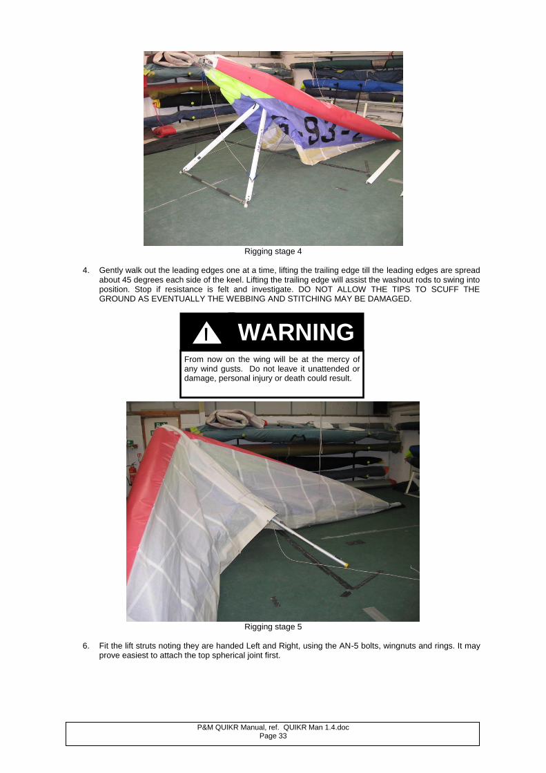
Rigging stage 4
4. Gently walk out the leading edges one at a time, lifting the trailing edge till the leading edges are spread
about 45 degrees each side of the keel. Lifting the trailing edge will assist the washout rods to swing into position. Stop if resistance is felt and investigate. DO NOT ALLOW THE TIPS TO SCUFF THE GROUND AS EVENTUALLY THE WEBBING AND STITCHING MAY BE DAMAGED.
Rigging stage 5
6. Fit the lift struts noting they are handed Left and Right, using the AN-5 bolts, wingnuts and rings. It may
prove easiest to attach the top spherical joint first.
From now on the wing will be at the mercy of any wind gusts. Do not leave it unattended or damage, personal injury or death could result.
WARNING !
P&M QUIKR Manual, ref. QUIKR Man 1.4.doc Page 34
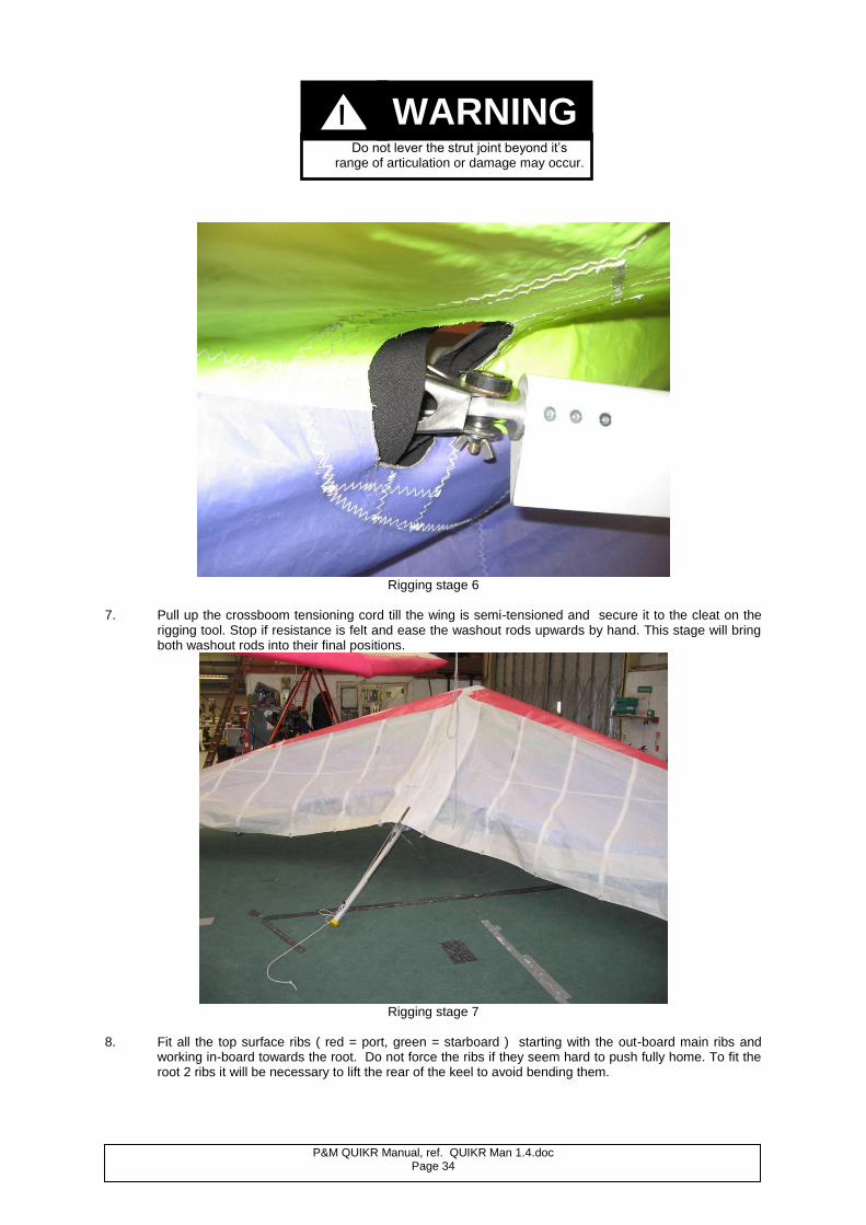
Rigging stage 6
7. Pull up the crossboom tensioning cord till the wing is semi-tensioned and secure it to the cleat on the
rigging tool. Stop if resistance is felt and ease the washout rods upwards by hand. This stage will bring both washout rods into their final positions.
Rigging stage 7
8. Fit all the top surface ribs ( red = port, green = starboard ) starting with the out-board main ribs and
working in-board towards the root. Do not force the ribs if they seem hard to push fully home. To fit the root 2 ribs it will be necessary to lift the rear of the keel to avoid bending them.
Do not lever the strut joint beyond it’s range of articulation or damage may occur.
WARNING !
P&M QUIKR Manual, ref. QUIKR Man 1.4.doc Page 35
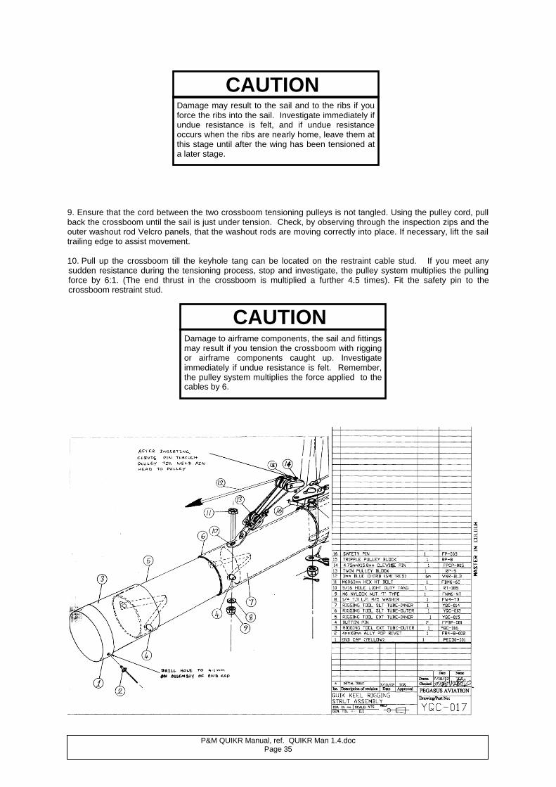
9. Ensure that the cord between the two crossboom tensioning pulleys is not tangled. Using the pulley cord, pull back the crossboom until the sail is just under tension. Check, by observing through the inspection zips and the outer washout rod Velcro panels, that the washout rods are moving correctly into place. If necessary, lift the sail trailing edge to assist movement. 10. Pull up the crossboom till the keyhole tang can be located on the restraint cable stud. If you meet any sudden resistance during the tensioning process, stop and investigate, the pulley system multiplies the pulling force by 6:1. (The end thrust in the crossboom is multiplied a further 4.5 times). Fit the safety pin to the crossboom restraint stud.
Damage may result to the sail and to the ribs if you force the ribs into the sail. Investigate immediately if undue resistance is felt, and if undue resistance occurs when the ribs are nearly home, leave them at this stage until after the wing has been tensioned at a later stage.
CAUTION
Damage to airframe components, the sail and fittings may result if you tension the crossboom with rigging or airframe components caught up. Investigate immediately if undue resistance is felt. Remember, the pulley system multiplies the force applied to the cables by 6.
CAUTION
P&M QUIKR Manual, ref. QUIKR Man 1.4.doc Page 36
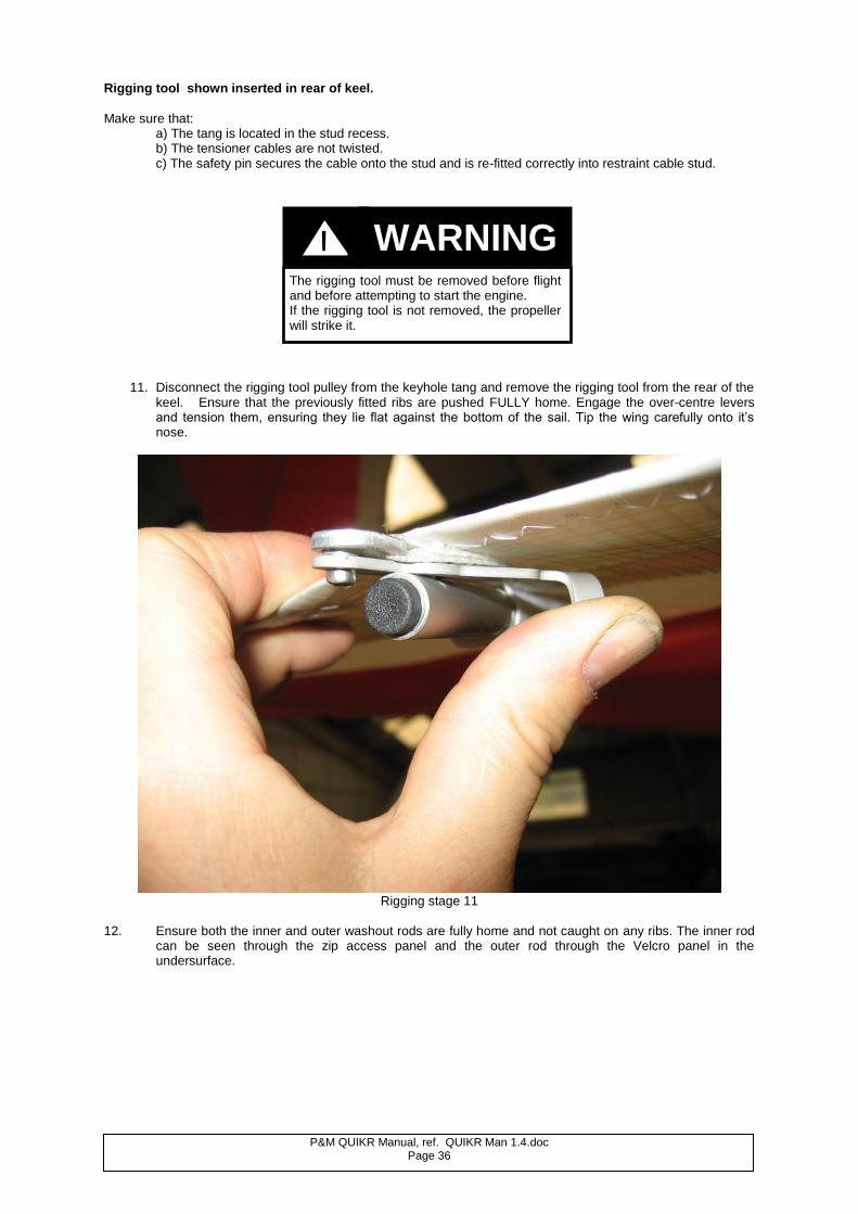
Rigging tool shown inserted in rear of keel.
Make sure that: a) The tang is located in the stud recess. b) The tensioner cables are not twisted. c) The safety pin secures the cable onto the stud and is re-fitted correctly into restraint cable stud.
``
11. Disconnect the rigging tool pulley from the keyhole tang and remove the rigging tool from the rear of the keel. Ensure that the previously fitted ribs are pushed FULLY home. Engage the over-centre levers and tension them, ensuring they lie flat against the bottom of the sail. Tip the wing carefully onto it’s nose.
Rigging stage 11
12. Ensure both the inner and outer washout rods are fully home and not caught on any ribs. The inner rod
can be seen through the zip access panel and the outer rod through the Velcro panel in the undersurface.
The rigging tool must be removed before flight and before attempting to start the engine. If the rigging tool is not removed, the propeller will strike it.
WARNING !
P&M QUIKR Manual, ref. QUIKR Man 1.4.doc Page 37
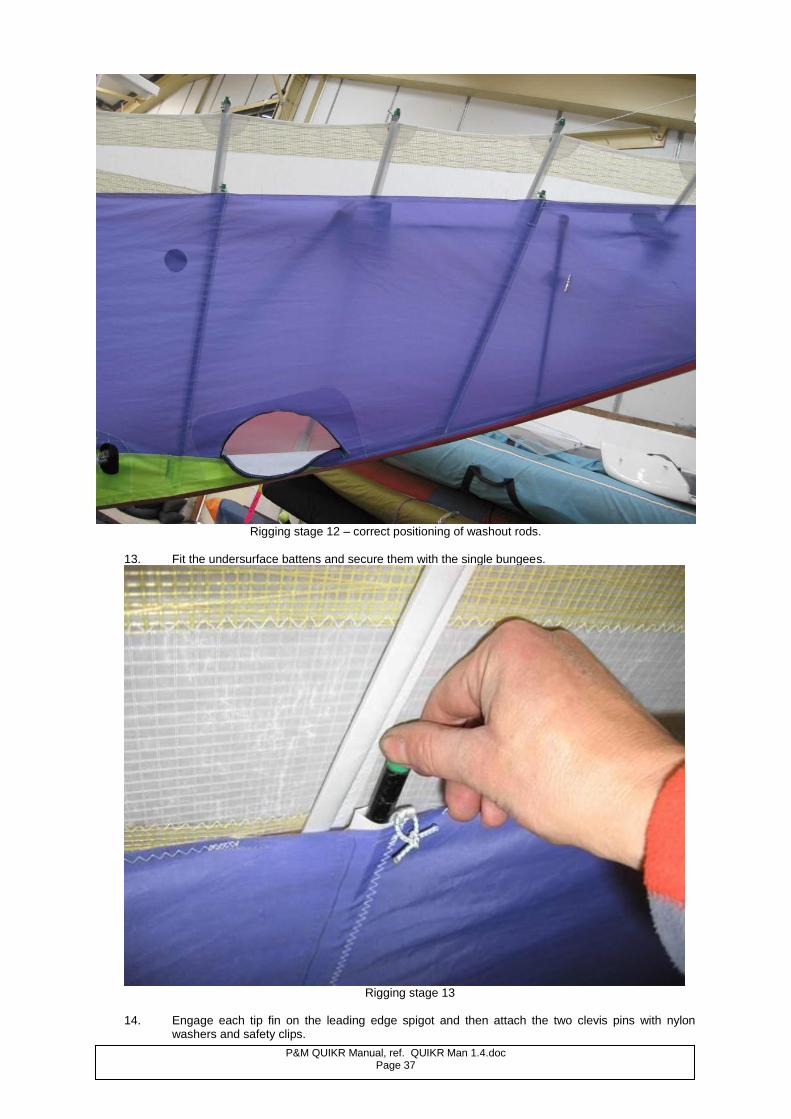
Rigging stage 12 – correct positioning of washout rods.
13. Fit the undersurface battens and secure them with the single bungees.
Rigging stage 13
14. Engage each tip fin on the leading edge spigot and then attach the two clevis pins with nylon
washers and safety clips.
P&M QUIKR Manual, ref. QUIKR Man 1.4.doc Page 38
``
15. Proceed to the front of the wing, lift and support the nose of the wing on the knee. Locate, fit and push
fully home the rigging tool to support the nose in the correct position for connecting the wing to the trike. Note: The following paragraphs 16 and 17 will normally be carried out after the trike has been attached to the
wing, but is detailed here for continuity. 16. After inspecting all parts visible through the nose aperture, securely fit the nose cone upper Velcro to
the wing top side Velcro and, ensuring symmetry, pull the lower part of the nose cone around the lower front rigging cables. Join the nose cone rigging cable slot edges with the Velcro’s provided and attach the nose cone underside to the wing undersurface Velcro.
17. Adjust either the upper or lower wing attachment Velcro patches to give the smoothest and most symmetrical fit.
5.3. PREPARING THE TRIKE
1. Rigging the trike is the relatively simple operation of lowering and raising the pylon whilst connecting the
trike to the wing. 2. To erect the trike from the folded state, the pylon should be raised and locked by means of the over-
centre catch.
Fit the front strut and ensure that the upper and lower securing pins and rings are fitted correctly. Now is a good time to inspect the interior of the trike including the engine mounts and fuel lines. Depress the drain valve on the underside of the fuel tank and drain off a little fuel into a container. Check for discolouration due to contamination and for water present in the fuel. If in doubt, drain off all contaminated fuel and replace it.
3. To convert the tandem seat for solo operation, it is merely necessary to secure the rear seat belt buckle and to tighten the straps so that there is no slack.
Nose cone must be fitted before flying. Failure to do so may adversely affect stability and control.
The pylon is fitted with a powerful gas strut to facilitate lifting of the wing. Handle the pylon with care when in the folded position with the wing off, and make sure you and all assistants remain clear of the pylon at all times when folded.
WARNING !
WARNING !
The aircraft becomes less directionally and laterally stable, especially at high speed/light weight/high power, if tip fins are not fitted. Trim speed is also reduced if tip fins are omitted. The tip fin vents must not be covered.
WARNING !
P&M QUIKR Manual, ref. QUIKR Man 1.4.doc Page 39
5.4. CONNECTING THE WING TO THE TRIKE For the first few times that you rig your aircraft, ensure that the weather is calm or you have an experienced helper to take charge if the wind starts to take control from you. It is much better to be set up on grass rather than hard standing, both to avoid damage and wear to the wing and scraped knuckles as you lift the wing from the ground. Ensure that the ground is level, clear of clutter, wing bags, tools, twigs and inspect the ground for holes or any other obstacles that may trip you. While rigging the aircraft, it is important to carry out continual checks to ensure correct assembly. It is important that the pilot/operator carries out these inspections to ensure that the aircraft will be fit to fly. 1. Fit the nose extension (rigging tool) to the wing and position the wing on it’s control frame and nose extension facing into wind. 2. Line up the trike behind and facing the wing, but at least ten feet away to give clearance for the wing to be raised onto its control frame. 3. Remove the two safety rings and pins at the lower end of the front strut . Release the over centre lock and then lift its lugs out of engagement and lay it aside, lay the front seat back rest down by rotating forward, lay the rear seat cushion down to expose the slot in the rear seat and lower the pylon by pulling firmly down on the inner front strut tube to overcome the resistance of the optional rigging gas strut where fitted. Remove the top front strut pin and lay the front strut on the ground, ensuring that it is not likely to cause a tripping hazard.
Release the trike brake and roll the trike forward with the front wheel rolling through the A frame and over the control bar. Make sure that the trike is aligned with the centre line of the wing and the pylon top is directly under the hang bracket. 3. Take the hang bolt and remove the nut, then centre the hang bracket.
Note: You may find it convenient to fashion two wooden wedges and jam them one each side of the hang bracket between the hang bracket and the uprights; these will hold the hang bracket firmly in a central position. Ensure they are removed immediately after the hang bolt has been fitted. Keeping hands and fingers clear, gently lift the pylon top to engage into the hang bracket. When the holes are aligned push the hang bolt through the hang bracket and pylon top assembly from the port (left) side. Engage and fully tighten the nut onto the hang bolt and clip the safety pin onto the hole in the toggle bar attached to the nut. 3.1 Connect the trim cord shackle to the keel at this stage.
Do not lean over the pylon or place any part of your body between the pylon and the wing. The gas strut (if fitted) is powerful and if the pylon inadvertently starts to raise it could cause injury.
Keep hands and fingers out from between the hang bracket and the A frame uprights as injury could result the hang bracket swinging to either side.
WARNING !
WARNING !
P&M QUIKR Manual, ref. QUIKR Man 1.4.doc Page 40
4. Go to the front of the wing and lift it to a horizontal position. Remove the nose extension, inspect the nose plate and cross boom hinge areas, attach the nose cone.
Lift the nose further while rolling the trike rearwards until the wing keel engages with its stop. The nose wheel of the trike will now be behind the control bar. Engage the trike parking brake. Check that the over centre catch on the wing top rear wire is fully home in the closed position and take a look inside the rear keel pocket to inspect the tensioning cables securing pin, correct tensioning cable run, rear keel, king post and fin tube attachment. 5. Lay the front strut within easy reach when you are stood at the nose of the trike. Stoop under the nose of the trike, facing rearwards, and if the wind is calm firmly clasp the control bar and lift it. If the wind is above 5 mph or gusting, then get a helper(s) to assist. Where a rigging gas strut is fitted, much of the weight of the wing will be almost immediately taken from you; where not fitted you will have to lever the wing up into position while supporting most of the 115 lb (52 kg) during part of the lift.
6. When the pylon is fully up, while still being ready to support the wing weight if a rigging gas strut is not fitted, locate the pylon using the over centre catch, but do not overcentre lock it at this stage. Get a helper to hold the bar or strap it back using the rear seat harness; if it is at all windy it is essential to have a helper at hand. Fit the front strut, first attaching it at the top with a pin and safety ring and then at the bottom with two pins and safety rings.
7. Face the aircraft into wind and set the parking brake.. Pull the control bar back till it contacts the seat and secure it there using the rear seat belt. If thermals etc are present, the aircraft may be picketed using weights or ground anchors on the side flying cables.
The nose cone must be attached to the wing and fully in place on its Velcro fixing. The wing stability and flying characteristics are adversely affected by flight without the nose cone fitted and could cause injury or death through loss of control.
Do not attempt to lift the wing to its rigged position without a rigging gas strut if you have back problems or if you are slight in stature. With wind input, you could find yourself with up to 110 lb (49 kg) of dead weight to carry. If you are unfit to carry this weight in a stooped position it is essential that a gas strut be fitted, or that you get an assistant to complete this task.
It is particularly important to check that the two lower pins pass through both the lower and upper sections of the front strut, and that the top connection is pinned. Failure to do so could result in structural failure.
Keep fingers and hands clear of the sides of the hang bracket at all times. The hang bracket operates on an overcentre system. If inadvertently let go, particularly in windy conditions, it could trap your fingers and cause injury.
WARNING ! WARNING !
WARNING !
WARNING !

P&M QUIKR Manual, ref. QUIKR Man 1.4.doc Page 41
6. PRE-FLIGHT INSPECTION 6.1. WING Action Done?
Nose catch secure, locking washer fitted
Leading-edge spar undented, shape correct
Crossboom junction secure, restraint webbing ok
Sail secure on tip, tip settings correct
Washout rods fully deployed
Upper strut connections secure, wingnuts and safety rings in position
Crossboom tensioner secure & not twisted, safety pin fitted
Keel pocket and rocker components undamaged
Hang-point secure and freely rotating
Control frame wingnuts and safety rings on basebar and lower strut fittings.
Trimmer set and functioning properly, trim cord attached to keel
Cables to control frame secure
Condition and security of composite flexible ribs
All other ribs secure, elastics fitted correctly & undamaged
Nose rib and nose cone secure and correctly fitted
Tip fins secure and correctly fitted
Rigging tool detached and stowed.
Inspection zippers and undersurface Velcro secured
6.2. TRIKE Action Done?
Ignition off; engine controls closed Front strut secure, safety rings attached Pylon catch locked Front tyre inflated and in good condition Front forks and suspension in good condition Axles secure Rear tyres inflated and in good condition Seat secure; harness straps secure, buckles functioning Throttles, choke control cables - condition OK, no kinks Engine mounting secure Exhaust secure Carburettor(s) secure, check for water or debris in float bowl Gearbox check for oil leaks Propeller secure and undamaged Plugs and leads secure Fuel contents adequate, check drain valve for water Brakes functioning correctly, check for leaks, parking brake lever OK Throttles - check both hand and foot for correct operation then set closed Steering functioning correctly Radiator coolant full, cap secure, overflow bottle pipe secure Coolant level overflow bottle approx. 1/3
rd
Hydraulic fluid reservoir level and cap secure. Engine oil level (nb turn engine SLOWLY till tank gurgles) Oil radiator cover secure (if fitted) and set appropriately for ambient temp.
Hang bolt secure, head on the LH side and tight as possible using hand, lanyard and clip in place.
You should never, under any circumstances, consider flying the aircraft before you have completed a thorough pre-flight check!
WARNING !
P&M QUIKR Manual, ref. QUIKR Man 1.4.doc Page 42
7. PREPARATION FOR FLIGHT 7.1. GENERAL Stow baggage carefully in the compartments provided. Do not exceed the loading limits or use non-authorised loading spaces. The space between the panel and the screen must not be used to store baggage or any other items unless they weigh less than 1kg and are secured by a lanyard. The wing rigging tool can be dismantled into 3 sections and stowed in a pouch under the rear seat. The pouch must be secured by the strap provided.
Before offering to take a passenger, ensure that you have ascertained that they do not suffer from any physical or mental condition that would make the flight hazardous either for the passenger and for the safety of the aircraft. Your first task before starting the engine is to seat your passenger (if applicable) in the aircraft, to check his/her harness, to check for loose objects, and then before having him/her put on a crash helmet, to give the following briefing:
PASSENGER BRIEFING:
Do not touch the ignition switches. Do not touch the hand throttle. Do not touch the control frame. Fold arms, or rest them on knees. No loose scarves, and tie up long hair. Ensure cameras, maps etc are secure. Pockets empty and no loose objects in the cockpit. Emergency exit from opposite side to the exhaust if possible. Describe takeoff, landing and intention of flight. Explain that there are hot and rotating engine parts directly behind which should not be touched in any circumstances. HELMET: A protective helmet must be worn, fit correctly and be secured. VISORS: A positive lock must be fitted to the visor and be engaged during flight. This is to ensure that the passenger does not wrench their head or neck if the wind should lift the visor, and also that it is not wrenched off completely where it will probably go into the propeller.
An inexperienced, inappropriately dressed or panic-stricken passenger could jeopardise the safety of the aircraft and crew. Ensure that you give all passengers the following briefing.
On Rotax 912S engines, ensure the passenger’s hair or scarf cannot get caught in the magneto.
1. You should never attempt to start the aircraft before satisfying yourself that the appropriate checks and procedures have been satisfactorily carried out (see below). 2. Rotating propellers (which are very difficult to see), hot coolant, hot and moving engine parts can all be very dangerous if not treated with due care and respect.
WARNING !
WARNING !
WARNING !
Baggage carried in unauthorised places can cause control obstruction, disruption to systems or and get loose & be caught in the propeller. Any of these outcomes can result in serious injury or death.
WARNING !
P&M QUIKR Manual, ref. QUIKR Man 1.4.doc Page 43
7.2. STRAPPING IN Lap straps should be adjusted snugly across the hips to reduce tendency for either occupant to slide forwards under the strap. Shoulder straps should be adjusted with a little slack to allow any necessary movement during flight and to ensure that the lap straps remain in place without slipping upwards in the event of accident.
Ballast for solo flight is not normally necessary, however if ballast is carried, it must be in a P&M Aviation approved container and securely strapped into the rear seat using lap and shoulder straps.
7.3. STARTING ENGINE The pilot must always start the engine when sitting in the cockpit with seatbelts secured and helmet worn.
Pre-start checks: 1. Passenger should also be strapped in and briefed. 2. Throttles both working and fully shut (never use the hand throttle for engine control on the ground).
If starter interrupt switch is fitted, starter will not operate unless hand throttle is CLOSED.
3. Check ignition switch operation and be prepared to turn off rapidly if required, before starting
according to paragraph 7.3 below.
Parking brake set. Check by pushing firmly on propeller hub (ensure that the ignition switches are in the OFF position before touching the propeller). Chock the aircraft securely. All controls should be checked closed and ignition should be off. The parking brake if fitted should be applied. Check the fuel is turned on.
ROTAX 912S/912 ENGINES: Before the first start of the day it is a good idea to turn the engine over for 2
bursts of about 5 seconds, IGNITION OFF, to get the oil pumping around the engine and to fill the float bowls. For the first start of the day use full choke, especially in very cold conditions. The choke system on the 4-stroke engines is progressive, unlike the 2-stroke’s, and the choke system automatically raises the idle speed quite considerably, so you MUST have brakes applied. For all other starts unless hot, use about 1/3 choke. Before start-up, check that both carbs are shut.
Failure to put on safety harness and wear front seat or rear seat shoulder straps could be the cause of injury or death in the event of an accident.
Engine start-up is always a potentially dangerous time. Make sure that you have done all your checks, that you are not disturbed while doing them, and that you are entirely happy that the aircraft is in a fit state to be started-up. Finally, before start-up, ensure that the aircraft is pointing away from people/vehicles/buildings etc, and that there are no pets or other animals which could panic after start-up. Double check that the propeller is clear and hand throttle is closed before starting the engine.
Ballast breaking free could cause injury or death in otherwise survivable accidents.
WARNING !
WARNING !
WARNING !
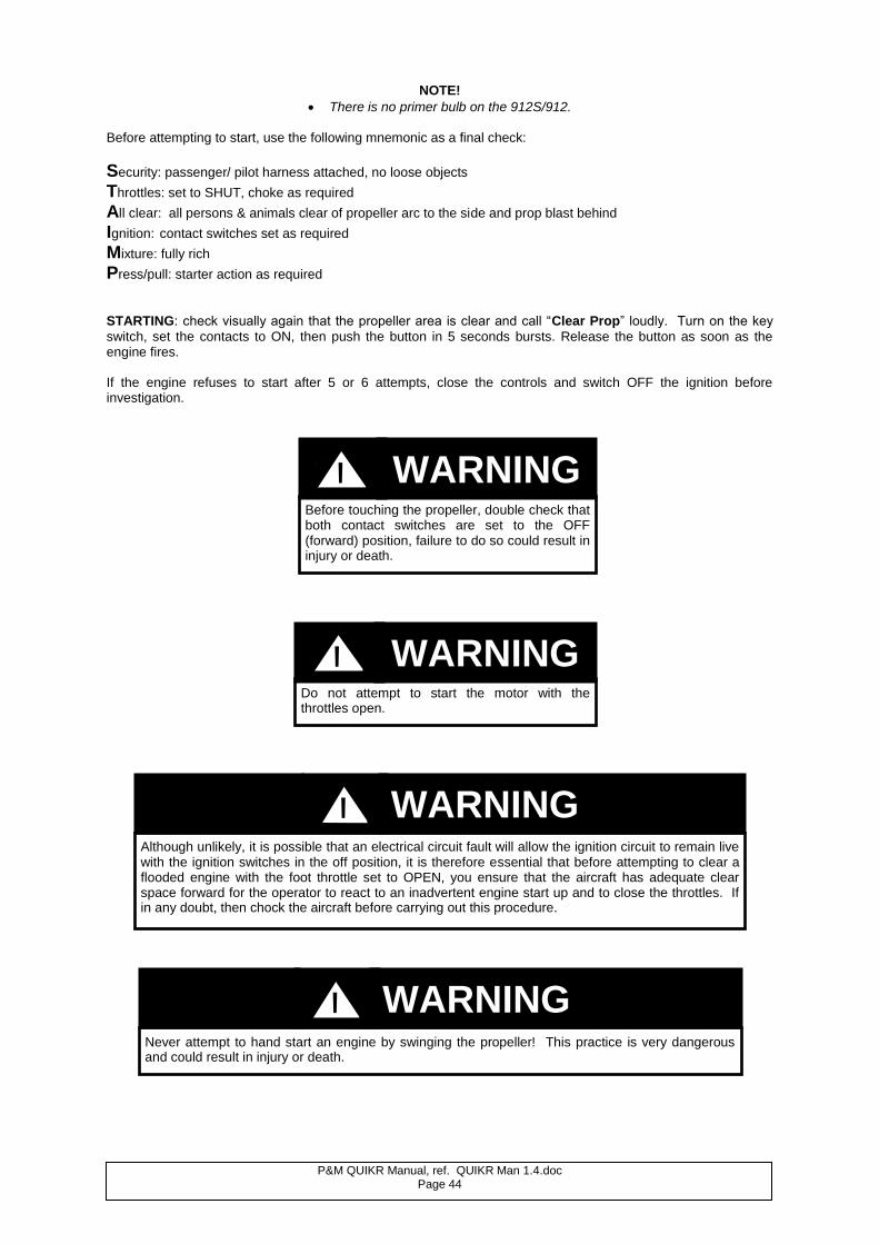
P&M QUIKR Manual, ref. QUIKR Man 1.4.doc Page 44
NOTE!
There is no primer bulb on the 912S/912. Before attempting to start, use the following mnemonic as a final check:
Security: passenger/ pilot harness attached, no loose objects
Throttles: set to SHUT, choke as required
All clear: all persons & animals clear of propeller arc to the side and prop blast behind
Ignition: contact switches set as required
Mixture: fully rich
Press/pull: starter action as required
STARTING: check visually again that the propeller area is clear and call “Clear Prop” loudly. Turn on the key
switch, set the contacts to ON, then push the button in 5 seconds bursts. Release the button as soon as the engine fires. If the engine refuses to start after 5 or 6 attempts, close the controls and switch OFF the ignition before investigation.
Before touching the propeller, double check that both contact switches are set to the OFF (forward) position, failure to do so could result in injury or death.
Never attempt to hand start an engine by swinging the propeller! This practice is very dangerous and could result in injury or death.
Although unlikely, it is possible that an electrical circuit fault will allow the ignition circuit to remain live with the ignition switches in the off position, it is therefore essential that before attempting to clear a flooded engine with the foot throttle set to OPEN, you ensure that the aircraft has adequate clear space forward for the operator to react to an inadvertent engine start up and to close the throttles. If in any doubt, then chock the aircraft before carrying out this procedure.
Do not attempt to start the motor with the throttles open.
WARNING !
WARNING !
WARNING !
WARNING !
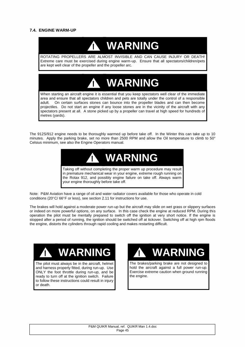
P&M QUIKR Manual, ref. QUIKR Man 1.4.doc Page 45
7.4. ENGINE WARM-UP
The 912S/912 engine needs to be thoroughly warmed up before take off. In the Winter this can take up to 10 minutes. Apply the parking brake, set no more than 2500 RPM and allow the Oil temperature to climb to 50° Celsius minimum, see also the Engine Operators manual.
Note: P&M Aviation have a range of oil and water radiator covers available for those who operate in cold
conditions (20C/ 66F or less), see section 2.11 for instructions for use. The brakes will hold against a moderate power run-up but the aircraft may slide on wet grass or slippery surfaces or indeed on more powerful options, on any surface. In this case check the engine at reduced RPM. During this operation the pilot must be mentally prepared to switch off the ignition at very short notice. If the engine is stopped after a period of running, the ignition should be switched off at tickover. Switching off at high rpm floods the engine, distorts the cylinders through rapid cooling and makes restarting difficult.
ROTATING PROPELLERS ARE ALMOST INVISIBLE AND CAN CAUSE INJURY OR DEATH! Extreme care must be exercised during engine warm-up. Ensure that all spectators/children/pets are kept well clear of the propeller and the propeller arc.
The brakes/parking brake are not designed to hold the aircraft against a full power run-up. Exercise extreme caution when ground running the engine.
When starting an aircraft engine it is essential that you keep spectators well clear of the immediate area and ensure that all spectators children and pets are totally under the control of a responsible adult. On certain surfaces stones can bounce into the propeller blades and can then become projectiles. Do not start an engine if any loose stones are in the vicinity of the aircraft with any spectators present at all. A stone picked up by a propeller can travel at high speed for hundreds of metres (yards).
Taking off without completing the proper warm up procedure may result in premature mechanical wear in your engine, extreme rough running on the Rotax 912, and possibly engine failure on take off. Always warm your engine thoroughly before take off.
The pilot must always be in the aircraft, helmet and harness properly fitted, during run-up. Use ONLY the foot throttle during run-up, and be ready to turn off at the ignition switch. Failure to follow these instructions could result in injury or death.
WARNING !
WARNING !
WARNING !
WARNING ! WARNING !
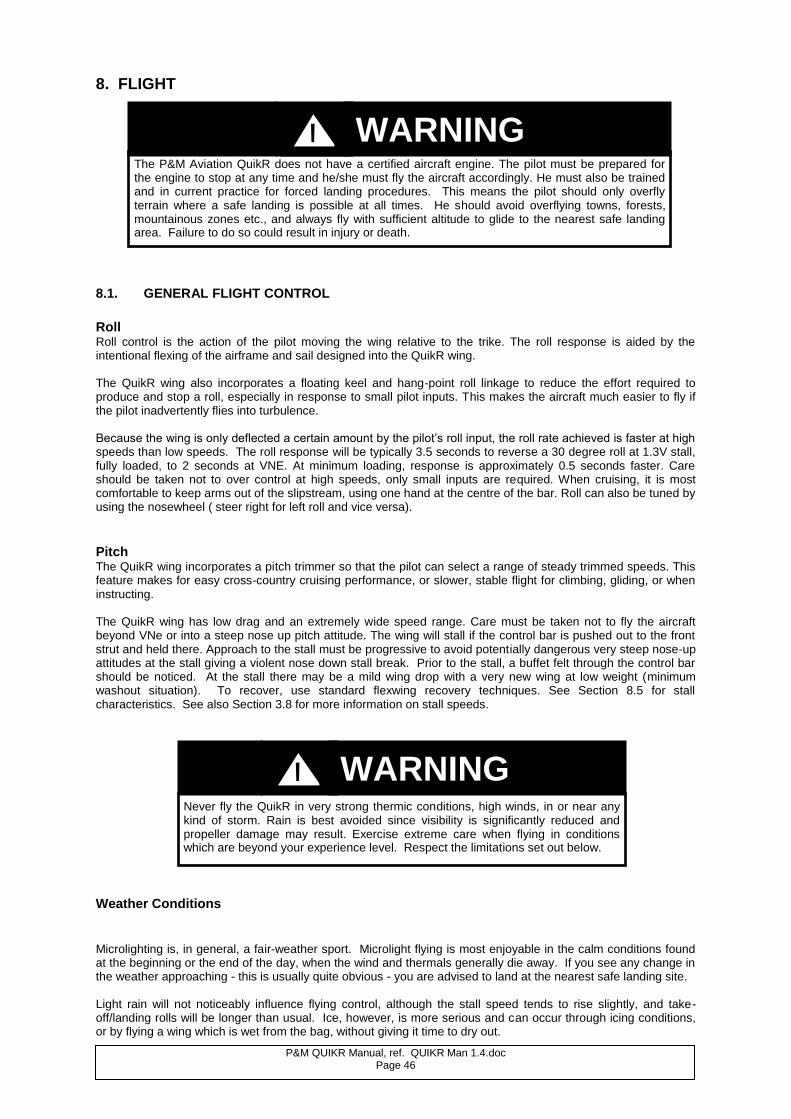
P&M QUIKR Manual, ref. QUIKR Man 1.4.doc Page 46
8. FLIGHT
8.1. GENERAL FLIGHT CONTROL
Roll Roll control is the action of the pilot moving the wing relative to the trike. The roll response is aided by the intentional flexing of the airframe and sail designed into the QuikR wing. The QuikR wing also incorporates a floating keel and hang-point roll linkage to reduce the effort required to produce and stop a roll, especially in response to small pilot inputs. This makes the aircraft much easier to fly if the pilot inadvertently flies into turbulence. Because the wing is only deflected a certain amount by the pilot’s roll input, the roll rate achieved is faster at high speeds than low speeds. The roll response will be typically 3.5 seconds to reverse a 30 degree roll at 1.3V stall, fully loaded, to 2 seconds at VNE. At minimum loading, response is approximately 0.5 seconds faster. Care should be taken not to over control at high speeds, only small inputs are required. When cruising, it is most comfortable to keep arms out of the slipstream, using one hand at the centre of the bar. Roll can also be tuned by using the nosewheel ( steer right for left roll and vice versa).
Pitch The QuikR wing incorporates a pitch trimmer so that the pilot can select a range of steady trimmed speeds. This feature makes for easy cross-country cruising performance, or slower, stable flight for climbing, gliding, or when instructing. The QuikR wing has low drag and an extremely wide speed range. Care must be taken not to fly the aircraft beyond VNe or into a steep nose up pitch attitude. The wing will stall if the control bar is pushed out to the front strut and held there. Approach to the stall must be progressive to avoid potentially dangerous very steep nose-up attitudes at the stall giving a violent nose down stall break. Prior to the stall, a buffet felt through the control bar should be noticed. At the stall there may be a mild wing drop with a very new wing at low weight (minimum washout situation). To recover, use standard flexwing recovery techniques. See Section 8.5 for stall characteristics. See also Section 3.8 for more information on stall speeds.
Weather Conditions Microlighting is, in general, a fair-weather sport. Microlight flying is most enjoyable in the calm conditions found at the beginning or the end of the day, when the wind and thermals generally die away. If you see any change in the weather approaching - this is usually quite obvious - you are advised to land at the nearest safe landing site. Light rain will not noticeably influence flying control, although the stall speed tends to rise slightly, and take-off/landing rolls will be longer than usual. Ice, however, is more serious and can occur through icing conditions, or by flying a wing which is wet from the bag, without giving it time to dry out.
The P&M Aviation QuikR does not have a certified aircraft engine. The pilot must be prepared for the engine to stop at any time and he/she must fly the aircraft accordingly. He must also be trained and in current practice for forced landing procedures. This means the pilot should only overfly terrain where a safe landing is possible at all times. He should avoid overflying towns, forests, mountainous zones etc., and always fly with sufficient altitude to glide to the nearest safe landing area. Failure to do so could result in injury or death.
Never fly the QuikR in very strong thermic conditions, high winds, in or near any kind of storm. Rain is best avoided since visibility is significantly reduced and propeller damage may result. Exercise extreme care when flying in conditions which are beyond your experience level. Respect the limitations set out below.
WARNING !
WARNING !
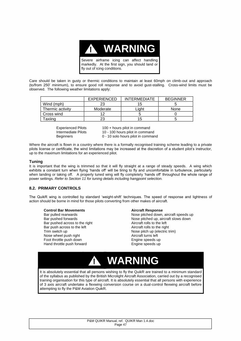
P&M QUIKR Manual, ref. QUIKR Man 1.4.doc Page 47
Care should be taken in gusty or thermic conditions to maintain at least 60mph on climb-out and approach (to/from 250’ minimum), to ensure good roll response and to avoid gust-stalling. Cross-wind limits must be observed. The following weather limitations apply:
EXPERIENCED INTERMEDIATE BEGINNER
Wind (mph) 23 15 5
Thermic activity Moderate Light None
Cross wind 12 5 0
Taxiing 23 15 5 Experienced Pilots 100 + hours pilot in command Intermediate Pilots 10 - 100 hours pilot in command Beginners 0 - 10 solo hours pilot in command
Where the aircraft is flown in a country where there is a formally recognised training scheme leading to a private pilots license or certificate, the wind limitations may be increased at the discretion of a student pilot’s instructor, up to the maximum limitations for an experienced pilot.
Tuning It is important that the wing is trimmed so that it will fly straight at a range of steady speeds. A wing which exhibits a constant turn when flying ‘hands off’ will be tiring to fly and uncomfortable in turbulence, particularly when landing or taking off. A properly tuned wing will fly completely ‘hands off’ throughout the whole range of power settings. Refer to Section 11 for tuning details including hangpoint selection. 8.2. PRIMARY CONTROLS The QuikR wing is controlled by standard ‘weight-shift’ techniques. The speed of response and lightness of action should be borne in mind for those pilots converting from other makes of aircraft.
Control Bar Movements Aircraft Response
Bar pulled rearwards Nose pitched down, aircraft speeds up Bar pushed forwards Nose pitched up, aircraft slows down Bar pushed across to the right Aircraft rolls to the left Bar push across to the left Aircraft rolls to the right Trim switch up Nose pitch up (electric trim) Nose wheel push right Aircraft turns left Foot throttle push down Engine speeds up Hand throttle push forward Engine speeds up
Severe airframe icing can affect handling markedly. At the first sign, you should land or fly out of icing conditions.
It is absolutely essential that all persons wishing to fly the QuikR are trained to a minimum standard of the syllabus as published by the British Microlight Aircraft Association, carried out by a recognised training organisation for this type of aircraft. It is absolutely essential that all persons with experience of 3 axis aircraft undertake a flexwing conversion course on a dual-control flexwing aircraft before attempting to fly the P&M Aviation QuikR.
WARNING !
WARNING !
P&M QUIKR Manual, ref. QUIKR Man 1.4.doc Page 48
8.3. GROUND HANDLING
Flexwing Microlights require special ground handling techniques. Parking
The QuikR is best parked into wind, though the wing down method may be used in light winds. Wing Down: Set the parking brake with the aircraft across and slightly downwind. Bank the into-wind wing down till the tip touches the ground. Apply the Velcro parking tie to the control frame. Into wind: Set the parking brake and face the aircraft into wind. Pull the control bar back till it contacts the seat and secure it there using the rear seat belt. If thermals etc are present, the aircraft may be picketed using cords to tangs fitted to the top strut connection bolts.
In stronger winds the trike pylon should be folded down. If necessary, after de-tensioning the wing and removing the battens, the wings can be folded back. See section 10.
Taxiing
Always taxi with great care and at a speed never greater than walking pace. For crosswinds, roll the into-wind wing downwards until you find a balanced position, and take care not to let the wind get underneath the into-wind wing when turning or taxiing. When taxiing into wind, hold the nose down. When taxiing downwind, push the nose up and taxi slightly faster than usual. See Table on previous page giving wind strength limitations.
Foot Operated Brake The foot operated brake consists of a lever operated by the left foot which controls a master cylinder mounted on the left side of the nose gear (disk brakes). In the disk system hydraulic pressure is fed through nylon tubing to slave callipers mounted on the wheels in the spatfins. There is also a parking brake incorporated which locks the brake pedal by means of a hand lever and detent system. To engage the parking brake, press the brake pedal and lift the hand lever until it engages with the hoop on the side of the steering assembly. Release occurs automatically when the brake pedal is pressed. The parking brake locking lever should be operated by hand only.
Note
Do not engage parking brake by pushing on the locking lever.
Brake Operating Limitations
When taxiing cross wind do not make the mistake of letting the up-wind wing go up as this will greatly increase the risk of the aircraft being blown over.
WARNING !
Never disconnect the nose shackle when the lift struts are attached. Never attempt to fold the control frame back when the lift struts are attached.
WARNING !
P&M QUIKR Manual, ref. QUIKR Man 1.4.doc Page 49
If the brake is needed during landing, exercise great care and remember the following procedures: 1. Apply the brake gently once the aircraft is stabilised after landing. 2. If the rear wheels lock and the aircraft starts to slide, release the pedal immediately and re-apply
more gently once the aircraft is stable once more.
Engine Run-Up Operators should note that with the engine running above idle the aircraft may tend to creep forward with the rear wheels locked on some surfaces. See warning Section 7.4.
Inspection The amount of wear that takes place on the tyres and brakes will vary from one aircraft to another, depending on the type of surface the aircraft normally takes off and lands on. Close inspection of the brake shoes should be made at intervals of no more than 100 hours. 8.4. TAKE-OFF Performance The takeoff performance given in section 3.8 is on short mown grass. Takeoff could be shorter from tarmac, but longer if from wet ground, if the ground slopes upwards, or if there is any tailwind. A significant headwind would reduce the length of the take-off run considerably; conversely, long grass or soft ground will considerably increase the take off run. See CAA safety sense leaflet 7A, performance.
Density altitude will affect take-off performance: for example at 4000 ft altitude the takeoff run will be 1.9 times as
long, and if the temperature is 32C at 4000 ft, the run will further increase to 2.1 times as long.
Before Take off Checklist Performance Calculations: (see above)
Wing visual check: nose, front rigging, side rigging, tip rods, ribs, rear rigging, hang-point bolt, control frame
and bolts, basebar bolts.
Trike: front strut pins/rings, brake operation, steering free, baggage box lids secure, harnesses, side skirts
secure, ignition switch check operation and magneto drop, intake and exhaust system secure, hand and foot throttle operation, mixture rich.
Magneto drop: check brakes on, at engine idle turn OFF both magneto switches, check for dead cut, and turn
on again. Idle speed should be set at around 1400 RPM for the Rotax 912S/912 engine. Run engine to 3850 RPM, then turn OFF front magneto. Listen for any misfire and observe mag drop (see also Engine Operators Manual). There must be a noticeable drop, which is accompanied by a slight change in engine note. Check the other magneto in the same way.
If the brake is used as an emergency landing brake in wet and icy conditions, extreme care must be exercised. If the aircraft veers, or the wheels lock, release the brake pedal immediately and steer towards the direction of the veer.
Exercise great care in strong crosswinds and turbulent conditions.
Before take-off or landing at altitude, in hot conditions, on a short strip and particularly in the case of a combinaton of all three, do your density altitude calculations.
If the wing is wet, take off distance can be up to 30% longer.
WARNING !
WARNING !
WARNING ! WARNING !
P&M QUIKR Manual, ref. QUIKR Man 1.4.doc Page 50
Then use the mnemonic CHIFTWAMP as follows:
CONTROLS: full and free movement of control bar, nose wheel.
HELMET & HARNESS: check both your own and particularly your passengers seat belt & harness.
INSTRUMENTS: all functioning, CHTs correct, Altimeter set, Oil temp and Oil pressure, altimeter set,
Intercom and Radio switched on and working.
FUEL: Fuel cap on, fuel tap on and fuel sufficient for planned journey + reserve.
TRIM: Set to takeoff position (as placarded on trim indicator ). WIND DIRECTION & STRENGTH: Within both aircraft and pilot limits?
ALL CLEAR: To taxi, to line up for finals, check for other aircraft in the circuit?
Mixture, Magnetos : Fully rich, both mags ON., battery charging.
POWER: When starting the takeoff roll, check that full power is available according to the following.
Abort the takeoff if full RPM is not reached or rough running occurs.
NOTE: FULL POWER STATIC RPM - Rotax 912UL-S ( Warp Drive) = 4800, min 4700. Rotax 912 ( Warp Drive) = 4950 min 4800.
Take-off Technique The hand throttle should not be used during take-off. Set the pitch trim control to the QuikR placarded take-off position. Check brakes are OFF. The correct technique on smooth surfaces is to allow the wing to trim in pitch during the initial stages of the take off run so as to reduce the drag and increase the acceleration. The QuikR demands a definite push to rotate on takeoff. In smooth air conditions, push forward until the aircraft unsticks at around 45mph (72km/h, 40kn) and then allow the aircraft to accelerate to 65-75mph (105 - 120km/h, 56-65kt) for the initial climb. When established in the climb, adjust the trimmer to remove the bar pressure and climb at 65mph. In smooth air conditions on rougher ground, push the bar out to its fullest extent for the whole takeoff run, to get the weight off the wheels as soon as possible. The trike unit will then swing forward under the wing. Allow the control bar to float back as this happens and climb away in the manner indicated above. It follows that taking off from rough ground in turbulent air conditions could either result in a slower takeoff speed than is desirable or in greater stress to the aircraft structure during a fast takeoff run. Therefore, consider carefully the advisability of flying in such circumstances.
Solo Flight Take-off The aircraft is only to be flown solo from the front seat. No ballast is required if the pilot weight is above 55 kg. The initial rotation of the trike to a nose-up attitude will be more pronounced when flying solo. For the initial 200 ft (61m) of climb, the attitude of the trike should be controlled to allow for the possibility of engine failure and airspeed should be maintained at 65-75mph. The full-power setting may have to be reduced to achieve a comfortable climb angle. Climb The speed at which maximum climb rate is achieved is 60 mph. Once established in the climb, the bar force can be removed with the trimmer. See the table in Section 3.5 for performance. All climb rate figures were taken at
450kgs (990lbs) Max AUW, sea level, 15C (59F) conditions (ISA). Beware of the effect of density altitude on the climb performance. The climb rate will reduce to around 0.65 of the sea level figure at 4000 ft, and if the
temperature at 4000 ft is 32C (90F), the factor will be 0.52. 8.5. EN-ROUTE During all aspects of flight the aircraft should be flown so that in the event of engine failure or loss of power, safe landing areas are always within reach. Providing the aircraft is being flown sensibly, the pilot has been trained and is in current forced landing practice, an engine failure should not lead to an accident and any competent and well-trained pilot will be able to cope.
DO NOT PERFORM STEEP CLIMB-OUTS. Allowing a steep climb to develop at a slow airspeed immediately after takeoff is dangerous. If the engine fails, the aircraft will pitch nose down through a large angle before taking up a glide. Roll control is also impaired at low airspeed. If at low level, there may not be enough time for recovery to landing mode, which could result in injury or death.
WARNING !
P&M QUIKR Manual, ref. QUIKR Man 1.4.doc Page 51
Levelling off into the cruise, set the attitude then the power setting and finally trim out the bar force using the trimmer knob or switch for pitch. The nosewheel steering can be used to provide some lateral trim, if required. (Left steering gives a small left yaw which translates into a slow right roll.) Once a steady cruise is set at a constant altitude, power and speed, the mixture may be leaned out observing the EGT limit of 800C. Monitor other engine limits before and after leaning. Revert to full rich before changing altitude, power or speed.
Descent Rate Fully loaded, the engine-off sink rate is around 500 fpm at 50 mph (80km/h, 43kn) and increases as speed is increased. Best glide angle is 9:1 at 57mph ( 1.5 nautical miles/1000 ft in still air)
Pitch Whether flown solo or dual, pitch control is very smooth and positive, progressive and damped, providing good “feel” at all times and in all manoeuvres. Pitch control is lighter when flown solo than dual. Pitch control force is also affected by the trimmer; heavier in the slow trim setting than the fast (less so with electric trim). If caught out in turbulent conditions, set trim to take-off to give more pitch feel. Fast trim should not exceed 100mph ( forward hangpoint) or 90mph ( rear hangpoint). If outside these limits, refer to section 11.
Roll Control and Turns At normal cruising speeds of 55 mph upwards, turns may be initiated by simply moving the control bar to the side away from the required direction of turn. As the turn develops, the control bar should be eased out to maintain the desired airspeed. As the desired bank angle is reached, the turn control input should be relaxed. Increasing bank angles requires increasing bar-out pitch control forces to coordinate the turn. Roll control becomes slower at low airspeeds, so the bar should be pulled in slightly to increase airspeed before commencing the turn. For roll-out the control bar is moved towards the lower wing tip, and the nose is lowered as the horizon levels. When the aircraft is flown solo, the roll response is faster for the same control force. Roll response is also less damped especially at high speeds in excess of 90 mph. Small control inputs should be used. Co-ordinated turns can be achieved with a maximum bar movement of 3 inches.
Trim – Longitudinal
The QuikR has a powerful electric trim system giving a very wide trim speed range of 55 – 100mph solo, 60-100 mph at maximum weight.
The aircraft should be set at the desired steady speed/attitude/power and then the trimmer operated to remove the pilot’s pitch force on the control bar. Trim for takeoff at the placarded position on the indicator, 65-70mph. Maximum rate of climb is at 60mph, but 70mph will still produce a strong climb and give better control in rough conditions. For landing approach, trim at 55-60mph solo, 60-65mph dual.
CLIMBING 1. Power 2. Attitude 3. Trim DESCENDING 1. Attitude 2. Power 3. Trim
Never pitch nose up or nose down more than
45 from the horizontal. Do not apply steep pitch attitudes at low airspeeds.
Do not exceed more than 60 of bank.
Every 10 minutes check fuel, engine temperatures, altitude & position.
WARNING !
WARNING !
WARNING !
P&M QUIKR Manual, ref. QUIKR Man 1.4.doc Page 52
Trim – Lateral
When cruising, the nosewheel can be used as a rudder to trim out mild turns or to provide mild course corrections. RIGHT nosewheel steering gives a RIGHT yaw which creates a slow LEFT hand turn. The effect is most noticeable above 70mph. The wing should be tuned straight enough to be turned slowly each way by this method.
Effect of Power Adjustment on Pitch As the thrust line is set low, the effect of reducing power is to lower the nose of the trike, and an increase in power will cause it to rise. The wing will continue to trim at a similar airspeed, power on or off.
Hand Throttle. The engine RPM can be set with the cruise control lever and then the pressure on the foot pedal may be removed until an increase in RPM is required. Thereafter, the RPM will always return to the cruise setting when foot pressure is removed. To obtain the full RPM range on the foot pedal, the hand throttle lever must be in the fully-off position.
Stall characteristics Fully loaded, the stall occurs at approximately 33 mph Min. AUW, 40 mph Max. AUW, and is clean and easily handled. As the speed is reduced, aft bar pressure increases, noticeably so immediately prior to the stall. You will also notice a slight nodding tendency and a stiffening of roll response. As the wing stalls, the nose pitches down and corrective action is to allow the bar to come back slightly to prevent the aircraft re-entering the stall state. Pulling the bar violently in to the chest and holding it there will result in an unnecessary rapid nose-down rotation and consequent steep nose-down attitude. The quickest stall recovery will result if the bar is allowed to come back no further than the trim position, then as soon as the trike nose drops below the horizon, power should be applied to check the nose down rotation, and then the pitch adjusted to resume normal flight. At the stall, a light wing drop may be found but is easily corrected. If necessary, hold the bar firmly to counter any tendency for the nose to pitch up excessively during the recovery. The P&M QuikR wing is remarkably stable, and even if stalled in a turn will not spin, but pitch down, increase air speed and roll out into a shallow turn or straight flight. On brand new wings, which have the least wash-out, if any pitch up or wing drop tendency is found, rotate both tips up 2 divisions. See tuning section. Stall recovery is fastest with the trimmer set slow, as the trimmer pitching moment applied to the wing will quickly pitch it out of the dive. It is recommended that stalling exercises are done with the trimmer in the middle position (approximately 75 mph).
Whip stalls and accelerated stalls producing steep nose-up attitudes at low airspeeds are very dangerous and absolutely forbidden. These manoeuvres can lead to loss of control and/or in flight structural failure that could result in injury or death.
Applying or removing power suddenly when near the ground can be dangerous.
Do not use the hand throttle for engine control on the ground or on take-off or landing.
WARNING !
WARNING !
WARNING !
P&M QUIKR Manual, ref. QUIKR Man 1.4.doc Page 53
8.6. LANDING Pre-approach checks: use the mnemonic FAWNTSIM
FUEL: sufficient to go around?
ALL CLEAR: long finals & runway clear?
WIND: strength & direction?
NOSEWHEEL: straight, hand throttle off, brakes off?
TRIM : set (60-65mph)?
SECURITY: harnesses/helmets tight?
INSTRUMENTS: set to QFE?
MIXTURE: fully rich?
NOTE
Periodically warm the engine in the descent, particularly in cold and moist conditions.
Because of the great speed range of the QuikR, the aircraft must be trimmed to a reduced speed for landing in order not to overshoot the runway. If the speed and/or the altitude are too high, make the decision to go around early. Short field operations should be practiced on a marked section of long runway first. The hand throttle should not be used during landing. Trim your approach airspeed down to 60-65 mph and be aware of wind gradient during strong wind days.
The flare is conventional (for a flexwing, but is of course opposite to a 3 axis aircraft), but the light pitch response can cause over correction and ‘ballooning’. Allow the speed to bleed off, and once established in ground effect gradually push out until the bar contacts the front strut as the main wheels touch. Safeguard the nosewheel by keeping the bar pushed out until the speed decays and the nosewheel drops. The practice of immediately pulling the bar in once on the ground puts unnecessary load on the nosewheel and should only be used in an emergency situation where the available stopping distance is marginal; in normal landings the wing should be set at a neutral incidence and the brakes used if required.
Crosswind Landing The QuikR copes well with cross-wind landings, but sensible pilots take great care to land into wind wherever possible. If a cross-wind landing is unavoidable, approach at slightly higher speed than normal, and then bleed off the speed 1 or 2 metres (3 to 6 ft) above the ground where the cross wind is least. Gently lower the mainwheels onto the ground, allowing them to drift until the trike is lined up with the runway. This is easiest on grass runways. Whenever possible utilise whatever into wind distance you can. Cross-wind components of up to 12 mph are within limits for pilots of average ability. Higher crosswind components have been safely demonstrated during test (see Section 4.1) but only experienced pilots should approach these limits. Such pilots should exercise great care in strong crosswind conditions. Because of the high torsional loads which can be imparted to the trike pylon and wing keel tube, always carry out a detailed inspection after every cross-wind landing, especially at the pylon top and bottom fittings.
Correct airspeed on finals is of great importance for engine-off landings. The approach speed must not be allowed to decay below 55 mph, and there must be a margin to permit rotation before touchdown.
Never approach at less than 55mph even lightly loaded in smooth conditions.
Locking the brakes can cause tyre damage on tarmac and snaking on wet grass. If they do lock, release the pedal immediately and apply more gently.
CAUTION
WARNING !
WARNING !
P&M QUIKR Manual, ref. QUIKR Man 1.4.doc Page 54
8.7. EMERGENCY PROCEDURES
Engine Failure in Flight You should always be flying within easy glide distance of a suitable forced landing area, and keep track of the wind direction. At any stage of your flight you should have your forced landing area selected. If your engine should stop, the first priority in any engine failure situation is to FLY THE AIRCRAFT. Set up a steady glide. The
best glide of the QuikR is approximately 9:1 at 57 mph, but this can be reduced to 4:1 at 90 mph. The second priority is to CONFIRM YOUR SELECTED FORCED LANDING AREA. Be particularly vigilant for power lines, electric fences, slopes and lee turbulence from obstacles. Determine wind direction from smoke, water ripples, cloud shadows (remember to mentally calculate for Coriolis effect) or otherwise if there is time,
make a steady 360 turn to determine drift. Refer to your map for altitude above the forced landing zone. Plan a proper approach into the area, and set up a glide towards it. With these things in mind, if there is time to attempt a restart, check: 1) Both ignition switches on. 2) Hand throttle closed. 3) Fuel contents ok. 4) Fuel turned on. 5) Choke off unless cold or if suspected fuel starvation. 6) Mixture fully rich 7) Foot throttle no more than 1/4 open. With the aircraft in a stable hands-off glide, operate the electric starter. FORCED LANDING DRILL: Throttles SHUT.
Both ignition switches OFF. Fuel OFF. Brakes OFF. Harness secure (do not overtighten pilots shoulder strap).
Plan approach. Engine-off Landings
The Approach The most important part of the approach is the base leg. Aim to start the base leg at approximately 800 feet agl and set up an approach speed glide of 60-65 mph. It is inadvisable to make the final approach slower than about 60 mph unless the field is very small, as wind gradient may reduce the airspeed too much and make the final flare unsuccessful. Gauge the right moment to turn onto finals at 4-500 feet as the base leg progresses. On finals, quite a lot of glide angle control can be made by varying the airspeed. The best technique is to maintain 60 mph airspeed through the wind gradient to a low level, say 10 ft, and then progressively ease the bar out as the speed decays until a smooth touchdown is made. Engine Failure on Take-Off (see WARNING in Section 8.4) In order to minimise the potential safety hazard in the event of an engine failure on take-off, never climb-out at a steep angle when close to the ground (an airspeed of not less than 60 mph is recommended for the first 200ft) and always use an airfield long enough to allow a safe engine off landing straight ahead when the aircraft is too low to turn into a shortened circuit. Resist the temptation to pull the control bar violently in after such a power failure as this will produce a steep nose down attitude. Instead, let the bar assume the neutral trim position until the aircraft regains airspeed and levels out. For minimum height loss, the nose-down rotation of the aircraft can be checked by pushing out once the nose has dropped below the horizon. The bar can then be eased in again to take up a glide. From that point, treat the situation as an engine off landing. Using the trimmer to trim hands-off at the climb speed gives increased pitch damping compared to using the fast trim setting. Always set trimmer prior to takeoff.
Always be prepared for the engine to fail when it is least convenient and therefore always ensure that you are within gliding distance of a suitable emergency landing field. Regular practice of glide approaches on engine idle will pay dividends. Warm the engine periodically when doing this.
WARNING !
P&M QUIKR Manual, ref. QUIKR Man 1.4.doc Page 55
Instrument Failure The essential instruments required by the conditions of the Permit to Fly are an altimeter and an airspeed indicator. In the event of failure of either of these it is not permissible to continue flying and a landing should be made as soon as it is possible and safe to do so. Failure of other instruments does not constitute grounds for abandoning a flight providing safety is not dependent upon them.
Engine Overheating With a well maintained engine, overheating should not occur. The two basic reasons are weakening of the fuel/air mixture, and cooling system failure. Condition of the fuel filter, float bowls and the fuel itself are very important. Check also the radiator, coolant level, condition of hoses. Fuel starvation may be detected by a sluggishness of the engine to respond to the throttle, a reduction in RPM, and a change in the exhaust note. If fuel starvation is suspected, then it may be possible to keep the engine running by pulling out the choke. Reducing the throttle setting may also keep the engine running. These measures should only be used to fly the aircraft to the nearest safe landing area, where a forced landing should be planned. If temperatures continue to rise, execute a forced landing as described above.
Fire If a fire occurs on the ground, then immediately close both throttles, switch OFF the engine and exit the aircraft, turning OFF the fuel as you go. A fire in the air is a considerably greater hazard. Two possible causes are electrical or fuel. Smoke or fire at the front of the aircraft is almost certain to be electrical in origin while occurrence at the rear could be from either cause. In the case of an electrical fire, turn OFF all electrical equipment and land as soon as is safely possible. In the case of a fuel fire, select a landing area, turn OFF the fuel and allow the engine to run until it stops. Turn OFF the ignition and perform an engine-off landing as described above.
Do not attempt to take off again without positively identifying the problem, solving it and running the engine at take off power for at least seven minutes.
Only use genuine streamline panniers part YQC-212. Other panniers can cause overheating.
WARNING ! WARNING !
P&M QUIKR Manual, ref. QUIKR Man 1.4.doc Page 56
9. POST FLIGHT INSPECTION After flight, and particularly if you have had a heavy landing or suspect damage may have occurred through ground handling or cross wind landings, you must inspect the aircraft thoroughly. Check the Maintenance and Repair section in this Manual. Even after a flight without incident you should still carry out a thorough Post-Flight Inspection, paying particular attention to:
The exhaust system
The propeller
The undercarriage, tyres & wheels
Loose objects
Oil and coolant levels
NOTE
If leaving the aircraft rigged, the trimmer should be left slack in the high speed position..
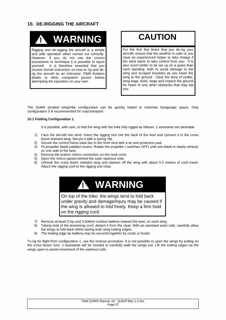
P&M QUIKR Manual, ref. QUIKR Man 1.4.doc Page 57
10. DE-RIGGING THE AIRCRAFT
The QuikR strutted wing/trike configuration can be quickly folded to minimise hangarage space. Only configuration 3 is recommended for road transport. 10.1 Folding Configuration 1.
It is possible, with care, to fold the wing with the trike fully rigged as follows. 2 assistants are desirable.
1) Face the aircraft into wind. Insert the rigging tool into the back of the keel and connect it to the cross boom restraint tang. Secure it with a spring clip.
2) Secure the control frame base bar to the front strut with a tie and protection pad. 3) Fit propeller blade padded covers. Rotate the propeller ( switches OFF) until one blade is nearly vertical,
on one side of the keel. 4) Remove the bottom Velcro connection on the nose cone. 5) Open the Velcro panels behind the outer washout rods. 6) Unhook the cross boom restraint tang and slacken off the wing with about 0.5 metres of cord travel.
Attach the rigging cord to the rigging tool cleat.
7) Remove at least 3 top and 3 bottom surface battens nearest the keel, on each wing 8) Taking hold of the tensioning cord, detach it from the cleat. With an assistant each side, carefully allow
the wings to fold back whilst raising both wing trailing edges. 9) The trailing edge tip battens may be secured together by cords or hooks.
To rig for flight from configuration 1, use the reverse procedure. It is not possible to open the wings by pulling on the cross boom cord. 2 assistants will be needed to carefully walk the wings out. Lift the trailing edges as the
wings open to assist movement of the washout rods.
Rigging and de-rigging the aircraft is a simple and safe operation when carried out correctly. However, if you do not use the correct procedures or technique it is possible to injure yourself. It is therefore essential that you receive formal instruction on how to rig and de-rig the aircraft by an instructor, P&M Aviation dealer or other competent person before attempting the operation on your own.
CAUTION
For the first few times that you de-rig your aircraft, ensure that the weather is calm or you have an experienced helper to take charge if the wind starts to take control from you. It is also much better to be set up on a grass than hard standing, both to avoid damage to the wing and scraped knuckles as you lower the wing to the ground. Clear the area of clutter, wing bags, tools, twigs and inspect the ground for holes or any other obstacles that may trip you.
WARNING !
On top of the trike, the wings tend to fold back under gravity and damage/injury may be caused if the wing is allowed to fold freely. Keep a firm hold on the rigging cord.
WARNING !
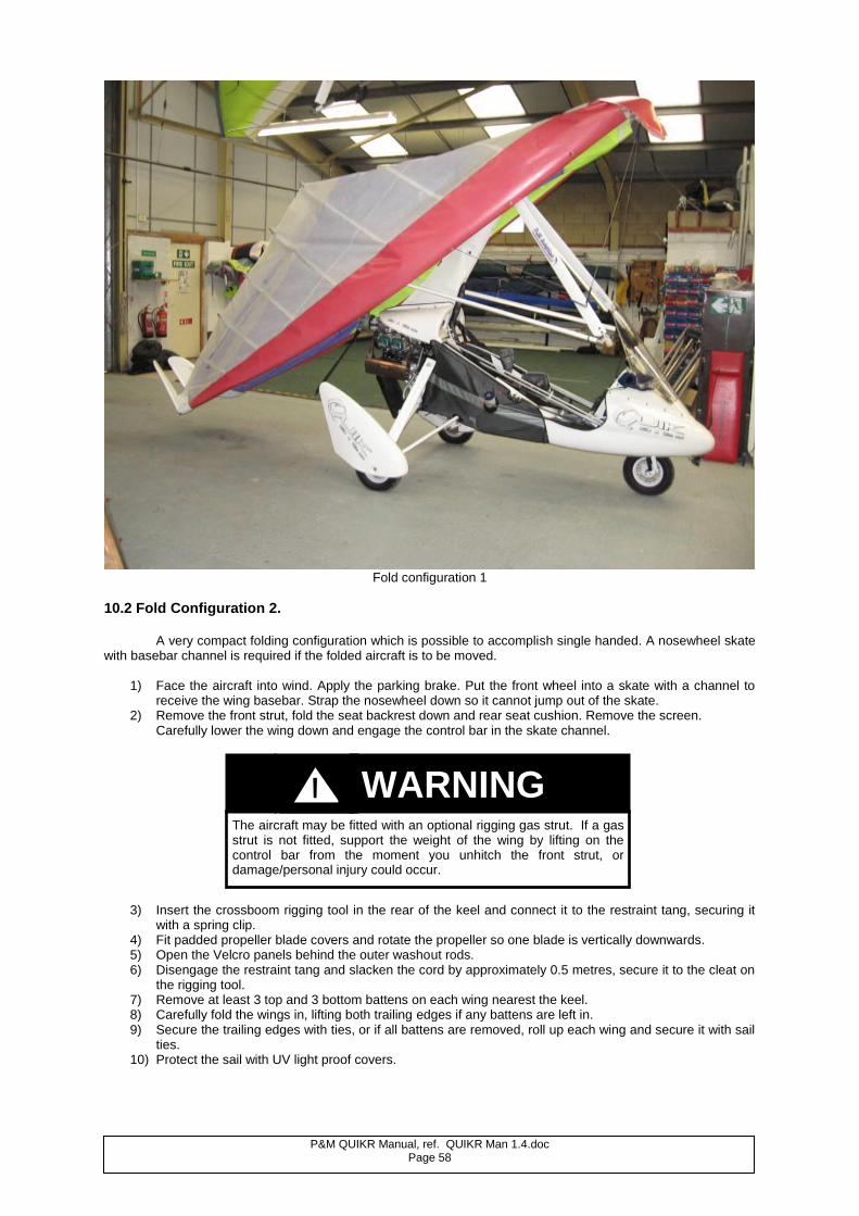
P&M QUIKR Manual, ref. QUIKR Man 1.4.doc Page 58
Fold configuration 1
10.2 Fold Configuration 2. A very compact folding configuration which is possible to accomplish single handed. A nosewheel skate with basebar channel is required if the folded aircraft is to be moved.
1) Face the aircraft into wind. Apply the parking brake. Put the front wheel into a skate with a channel to receive the wing basebar. Strap the nosewheel down so it cannot jump out of the skate.
2) Remove the front strut, fold the seat backrest down and rear seat cushion. Remove the screen. Carefully lower the wing down and engage the control bar in the skate channel.
3) Insert the crossboom rigging tool in the rear of the keel and connect it to the restraint tang, securing it
with a spring clip. 4) Fit padded propeller blade covers and rotate the propeller so one blade is vertically downwards. 5) Open the Velcro panels behind the outer washout rods. 6) Disengage the restraint tang and slacken the cord by approximately 0.5 metres, secure it to the cleat on
the rigging tool. 7) Remove at least 3 top and 3 bottom battens on each wing nearest the keel. 8) Carefully fold the wings in, lifting both trailing edges if any battens are left in. 9) Secure the trailing edges with ties, or if all battens are removed, roll up each wing and secure it with sail
ties. 10) Protect the sail with UV light proof covers.
The aircraft may be fitted with an optional rigging gas strut. If a gas strut is not fitted, support the weight of the wing by lifting on the control bar from the moment you unhitch the front strut, or damage/personal injury could occur.
WARNING !
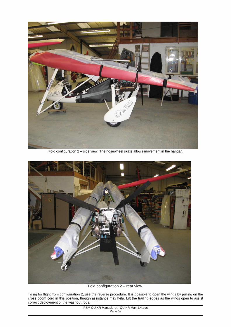
P&M QUIKR Manual, ref. QUIKR Man 1.4.doc Page 59
Fold configuration 2 – side view. The nosewheel skate allows movement in the hangar.
Fold configuration 2 – rear view.
To rig for flight from configuration 2, use the reverse procedure. It is possible to open the wings by pulling on the cross boom cord in this position, though assistance may help. Lift the trailing edges as the wings open to assist correct deployment of the washout rods.
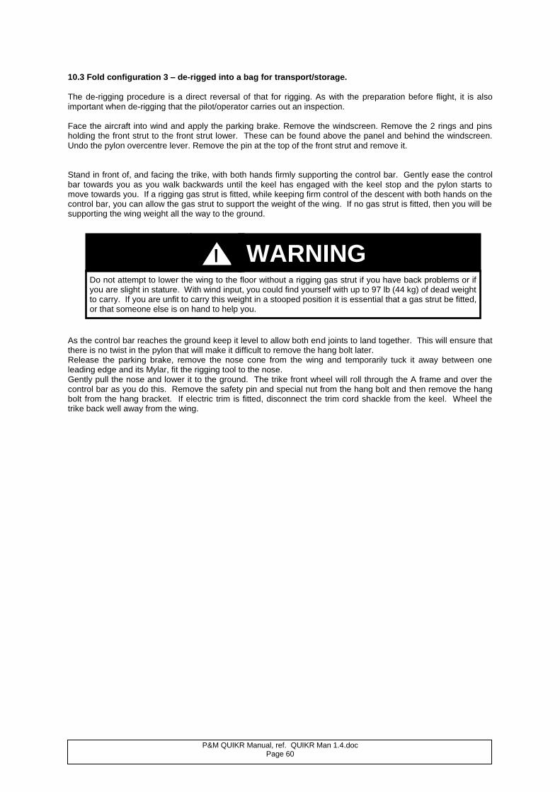
P&M QUIKR Manual, ref. QUIKR Man 1.4.doc Page 60
10.3 Fold configuration 3 – de-rigged into a bag for transport/storage.
The de-rigging procedure is a direct reversal of that for rigging. As with the preparation before flight, it is also important when de-rigging that the pilot/operator carries out an inspection. Face the aircraft into wind and apply the parking brake. Remove the windscreen. Remove the 2 rings and pins holding the front strut to the front strut lower. These can be found above the panel and behind the windscreen. Undo the pylon overcentre lever. Remove the pin at the top of the front strut and remove it. Stand in front of, and facing the trike, with both hands firmly supporting the control bar. Gently ease the control bar towards you as you walk backwards until the keel has engaged with the keel stop and the pylon starts to move towards you. If a rigging gas strut is fitted, while keeping firm control of the descent with both hands on the control bar, you can allow the gas strut to support the weight of the wing. If no gas strut is fitted, then you will be supporting the wing weight all the way to the ground.
As the control bar reaches the ground keep it level to allow both end joints to land together. This will ensure that there is no twist in the pylon that will make it difficult to remove the hang bolt later. Release the parking brake, remove the nose cone from the wing and temporarily tuck it away between one leading edge and its Mylar, fit the rigging tool to the nose. Gently pull the nose and lower it to the ground. The trike front wheel will roll through the A frame and over the control bar as you do this. Remove the safety pin and special nut from the hang bolt and then remove the hang bolt from the hang bracket. If electric trim is fitted, disconnect the trim cord shackle from the keel. Wheel the trike back well away from the wing.
Do not attempt to lower the wing to the floor without a rigging gas strut if you have back problems or if you are slight in stature. With wind input, you could find yourself with up to 97 lb (44 kg) of dead weight to carry. If you are unfit to carry this weight in a stooped position it is essential that a gas strut be fitted, or that someone else is on hand to help you.
WARNING !
P&M QUIKR Manual, ref. QUIKR Man 1.4.doc Page 61
After detaching the wing from the trike, reverse the procedures listed in Section 5.2. When preparing the wing for stowage in the bag, furl the wing fabric carefully, ensuring that the protection patches are correctly positioned at the following positions: a) Control frame knuckle joints and rigging cable connections. b) Roll bracket and upper control frame. c) Keel restraint stud area. Rigging cables should be stowed carefully so as to avoid kinks and tangles. When using the pulley system to release the crossboom tension, pay out the cord steadily to avoid rope burns to your skin.
10.4. RIGGED WING STORAGE If storing the wing alone rigged, it should be parked in a sheltered location nose-down with rigging extension inserted. Undo the wing undersurface inspection zips and pass tie-down ropes around the cross-boom or side-wires. The nose cone should be removed and stowed under the leading edge Mylar. The basebar and nose should rest on a soft, even surface; in particular avoid sharp stones which can damage the basebar.
10.5. WING OVERNIGHT PARKING
For overnight parking, unless winds are forecast to be very light, the wing should be positioned into wind and folded down as in configuration 2 but with the control bar on the ground.
CAUTION
Keep a firm grip on the pylon to ensure that the rigging gas strut does not shoot it into the upright position. Do not lean over the lowered pylon at any time as injury could result from it inadvertently erecting.
Keep hands and fingers out from between the control frame sides and the hang bracket as injury could result.
Never store a wet wing in a sealed bag. This may result in mildew on the sail or general degradation of the airframe and fittings. If possible dry the wing before de-rigging. Otherwise open the bag zip before the wing is stored.
WARNING !
Never disconnect the nose shackle when the lift struts are attached. Never attempt to fold the control frame back when the lift struts are attached.
WARNING !
P&M QUIKR Manual, ref. QUIKR Man 1.4.doc Page 62
11. TUNING THE WING
11.1. NEW AIRCRAFT
11.2. WING TUNING A well tuned wing will fly in a straight line hands-off and will respond to control inputs equally in each direction. However, fabric can stretch slightly with age and ribs can alter shape and get bent or distorted. The most common problem with flexwings is the tendency for the wing to acquire a turn one way which can be irritating and tiring on a long flight. Turns like this can be tuned out and are invariably due to rib shape or tip setting problems. However, it may be that airframe damage has occurred so if a turn becomes apparent the first thing to do is to check the frame carefully, inspecting for bends and distortion particularly in the leading edges. If the frame is alright, you should check the ribs against the template and adjust accordingly. In fast cross country flight the nosewheel can be used as a trimmer ( nosewheel right = slow left turn in flight). With a well tuned machine, in smooth conditions it should be possible to cruise with arms folded, making course corrections using the nosewheel.
Prior to delivery to the customer all new aircraft are flown and set up by either the Factory or by Appointed Dealers. A full check flight is carried out and adjustments made to the wing to ensure that it is properly trimmed out and flies hands off at the right speed. Owners are discouraged from making any adjustments. If you feel your new P&M aircraft is not performing as it should, it is essential that your dealer is immediately informed. The following notes are for guidance only. Since tuning of flexwings is a specialised technical procedure, no adjustment should be made without a full understanding of the principles involved. Please observe the following simple guidelines: 1. Before making any adjustments check for correct rib profiles against the rib plan supplied. If the aircraft is
not new, then also check the airframe components, particularly the outer leading edges. 2. Never exceed the adjustments specified in this Tuning Guide. 3. Make notes of every adjustment made. Only ever make one adjustment at a time, and carry out a flight test
to gauge the effect before making further adjustments. 4. When the exercise is complete, you should discuss any adjustments made with your Instructor or Dealer
and then enter them in the Aircraft Technical Log. 5. If you cannot get the aircraft to fly as it should, then first return all the settings to standard and reassess the
situation. If this cannot be made to work, contact your Dealer immediately.
WARNING !
Those operators who wish to tune the QuikR wing should contact a P&M Aviation agency for additional advice. Before any tuning is attempted, a careful and thorough check of the airframe is essential. A sudden indication that the wing requires tuning may be the result of damage caused in an unreported accident or from a heavy landing. Unless your are an experienced flexwing pilot, you should ask your Instructor/Dealer or Inspector to assist with all tuning operations and have him/her carry out the flight tests.
WARNING !
P&M QUIKR Manual, ref. QUIKR Man 1.4.doc Page 63
11.3. TUNING GUIDE For successful tuning, the weather conditions must be smooth, small adjustments must be made ONE AT A TIME, and notes must be made immediately any changes have been made and check flown. The loading of the aircraft must also be similar for trials to have comparable results. The settings of the washout rods are critical. If they are too high, roll handling will be adversely affected. If they are much too high, trim speed will also reduce. If the washout rods are too low, the wing may become unstable in pitch during turbulence or in steep dives. The washout rods should not be used to attempt to tune out turns.
11.3.1 Tuning turns Example:
The aircraft turns right at all speeds. The trim speed is correct. Solution:
In this case use asymmetric movement of the tip turn adjusters. On the tips you will find an adjustment scale where the leading edge emerges from the sail. See the diagram below for the standard factory setting. Rotate the starboard tip plug 1mm down on the scale and the port tip plug 1mm up on the scale. Check in flight. If the turn persists, rotate the tips one further mm. Check fly until the turn is removed.
Example: At high speed, the aircraft turns to the right. At low speed, the turn is not so pronounced. The trim
speed is correct. Solution: Use ribs numbers 7-9 (the tip rib is number 10 and has very little effect) on the starboard (right wing) side to
tune out the turn. The tip ribs respond well to “tab effect”, i.e. application of reflex near to the trailing edge will produce a downforce at the trailing edge which will increase the incidence of the section as a whole. The overall effect is to increase the lift on the side where reflex is applied, so correcting the turn. The effect becomes more pronounced as the speed rises. The reflex should be applied 230mm from the trailing edge and applied in small increments up to a maximum of 20mm. Start with 5mm reflex, test fly, then adjust in 5mm increments as required .Do not exceed 20mm reflex!
Do not exceed the adjustment range which is ±6mm (1/4 inch) from the initial factory setting, or the aircraft may become unstable.
Never lower the washout rods below the factory setting. See section 12. If the wing used to fly straight but has recently developed a significant turn, then the probability is that damage has occurred. It is necessary to strip and inspect the aircraft before your next flight. Failure to do so may result in injury or death.
WARNING !
WARNING !
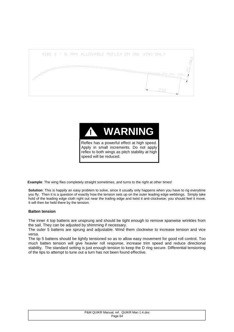
P&M QUIKR Manual, ref. QUIKR Man 1.4.doc Page 64
Example: The wing flies completely straight sometimes, and turns to the right at other times!
Solution: This is happily an easy problem to solve, since it usually only happens when you have to rig everytime
you fly. Then it is a question of exactly how the tension sets up on the outer leading edge webbings. Simply take hold of the leading edge cloth right out near the trailing edge and twist it anti-clockwise; you should feel it move. It will then be held there by the tension. Batten tension The inner 4 top battens are unsprung and should be tight enough to remove spanwise wrinkles from the sail. They can be adjusted by shimming if necessary. The outer 5 battens are sprung and adjustable. Wind them clockwise to increase tension and vice versa. The tip 5 battens should be lightly tensioned so as to allow easy movement for good roll control. Too much batten tension will give heavier roll response, increase trim speed and reduce directional stability. The standard setting is just enough tension to keep the D ring secure. Differential tensioning of the tips to attempt to tune out a turn has not been found effective.
Reflex has a powerful effect at high speed. Apply in small increments. Do not apply reflex to both wings as pitch stability at high speed will be reduced.
WARNING !
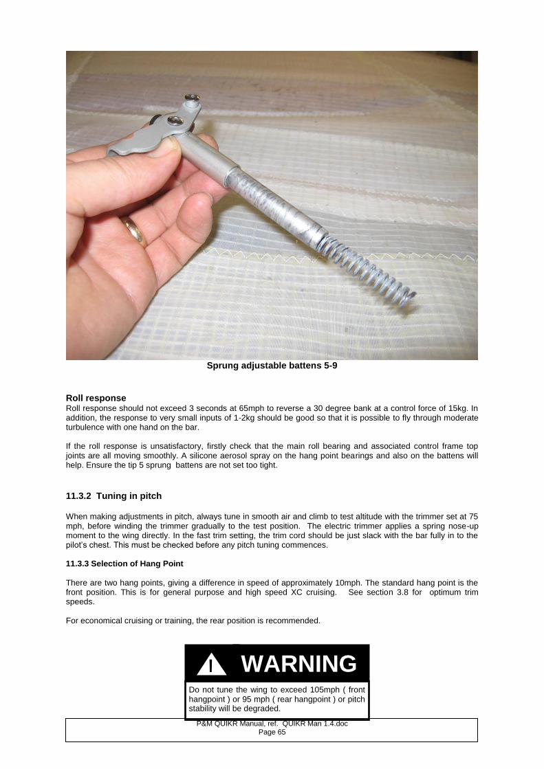
P&M QUIKR Manual, ref. QUIKR Man 1.4.doc Page 65
Sprung adjustable battens 5-9
Roll response Roll response should not exceed 3 seconds at 65mph to reverse a 30 degree bank at a control force of 15kg. In addition, the response to very small inputs of 1-2kg should be good so that it is possible to fly through moderate turbulence with one hand on the bar. If the roll response is unsatisfactory, firstly check that the main roll bearing and associated control frame top joints are all moving smoothly. A silicone aerosol spray on the hang point bearings and also on the battens will help. Ensure the tip 5 sprung battens are not set too tight.
11.3.2 Tuning in pitch When making adjustments in pitch, always tune in smooth air and climb to test altitude with the trimmer set at 75 mph, before winding the trimmer gradually to the test position. The electric trimmer applies a spring nose-up moment to the wing directly. In the fast trim setting, the trim cord should be just slack with the bar fully in to the pilot’s chest. This must be checked before any pitch tuning commences. 11.3.3 Selection of Hang Point
There are two hang points, giving a difference in speed of approximately 10mph. The standard hang point is the front position. This is for general purpose and high speed XC cruising. See section 3.8 for optimum trim speeds. For economical cruising or training, the rear position is recommended.
Do not tune the wing to exceed 105mph ( front hangpoint ) or 95 mph ( rear hangpoint ) or pitch stability will be degraded.
WARNING !
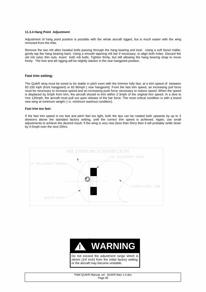
P&M QUIKR Manual, ref. QUIKR Man 1.4.doc Page 66
11.3.4 Hang Point Adjustment
Adjustment of hang point position is possible with the whole aircraft rigged, but is much easier with the wing removed from the trike. Remove the two m6 allen headed bolts passing through the hang bearing and keel. Using a soft faced mallet, gently tap the hang bearing back. Using a smooth tapering m6 bar if necessary, to align both holes. Discard the old m6 nyloc thin nuts. Insert both m6 bolts. Tighten firmly, but still allowing the hang bearing strap to move freely. The fore and aft rigging will be slightly slacker in the rear hangpoint position.
Fast trim setting: The QuikR wing must be tuned to be stable in pitch even with the trimmer fully fast, at a trim speed of between 92-100 mph (front hangpoint) or 82-90mph ( rear hangpoint). From the fast trim speed, an increasing pull force must be necessary to increase speed and an increasing push force necessary to reduce speed. When the speed is displaced by 5mph from trim, the aircraft should re-trim within 2-3mph of the original trim speed. In a dive to Vne 120mph, the aircraft must pull out upon release of the bar force. The most critical condition is with a brand new wing at minimum weight ( i.e. minimum washout condition). Fast trim too fast:
If the fast trim speed is too fast and pitch feel too light, both the tips can be rotated both upwards by up to 3 divisions above the standard factory setting, until the correct trim speed is achieved. Again, use small adjustments to achieve the desired result. If the wing is very new (less than 5hrs) then it will probably settle down by 4-5mph over the next 20hrs.
Do not exceed the adjustment range which is ±6mm (1/4 inch) from the initial factory setting, or the aircraft may become unstable.
WARNING !
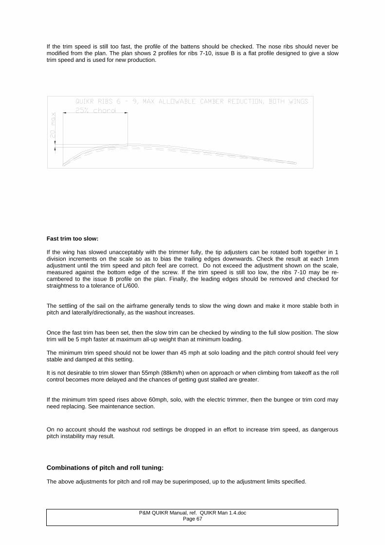
P&M QUIKR Manual, ref. QUIKR Man 1.4.doc Page 67
If the trim speed is still too fast, the profile of the battens should be checked. The nose ribs should never be modified from the plan. The plan shows 2 profiles for ribs 7-10, issue B is a flat profile designed to give a slow trim speed and is used for new production.
Fast trim too slow:
If the wing has slowed unacceptably with the trimmer fully, the tip adjusters can be rotated both together in 1 division increments on the scale so as to bias the trailing edges downwards. Check the result at each 1mm adjustment until the trim speed and pitch feel are correct. Do not exceed the adjustment shown on the scale, measured against the bottom edge of the screw. If the trim speed is still too low, the ribs 7-10 may be re-cambered to the issue B profile on the plan. Finally, the leading edges should be removed and checked for straightness to a tolerance of L/600. The settling of the sail on the airframe generally tends to slow the wing down and make it more stable both in pitch and laterally/directionally, as the washout increases. Once the fast trim has been set, then the slow trim can be checked by winding to the full slow position. The slow trim will be 5 mph faster at maximum all-up weight than at minimum loading. The minimum trim speed should not be lower than 45 mph at solo loading and the pitch control should feel very stable and damped at this setting. It is not desirable to trim slower than 55mph (88km/h) when on approach or when climbing from takeoff as the roll control becomes more delayed and the chances of getting gust stalled are greater. If the minimum trim speed rises above 60mph, solo, with the electric trimmer, then the bungee or trim cord may need replacing. See maintenance section. On no account should the washout rod settings be dropped in an effort to increase trim speed, as dangerous pitch instability may result.
Combinations of pitch and roll tuning: The above adjustments for pitch and roll may be superimposed, up to the adjustment limits specified.
P&M QUIKR Manual, ref. QUIKR Man 1.4.doc Page 68
12. MAINTENANCE 12.1. GENERAL Apart from the consequences of heavy landing, or of exceeding flight limitations, the major factors for attention are corrosion, fatigue and UV light. There is no inherent fatigue problem with the P&M QuikR, but excessive loads and vibration can weaken the structure, and a regular watch for hair-line cracks, most likely in areas under high stress, such as around bolt holes, should be carried out. All components can be replaced without difficulty. Repairs should be undertaken by a P&M Aviation Ltd. approved repair agency. Aluminium Tubework
Care and consideration in de-rigging and transportation will pay huge dividends in airframe life. Any damage to any one of the structural members is serious and can usually only be repaired by replacement. Tubes suffer from abrasion or indentation, the first accelerating fatigue fracture and the second reducing the strength of the part. If you bend, dent or damage the tubular members in any way, seek immediate professional advice before flying again and have replacement parts fitted. All tubes are intended to be straight when unloaded, with the exceptions of the pylon, seat frame, inner washout rod and top surface battens. See inspection schedule 12.5.
Fasteners Only fasteners purchased from P&M Aviation Ltd either direct or through an Approved Stockist should be used for replacement. Any fastener which is bent or shows sign of wear or corrosion should be immediately replaced.
Rigging Cables The main danger with the rigging lies in kinking the cable, usually caused by careless rigging and de-rigging. Once a cable has a kink, the strands are damaged and replacement is the only cure. Check for cable damage along the length but the main failure area lies immediately adjacent to the swaged fitting. Look carefully for signs of strand fracture at this position. Corrosion is a serious problem particularly in coastal areas and shows itself as a white powdery deposit. Corrosion cannot be cured and replacement is the only answer.
Fittings Many fittings on P&M aircraft are manufactured from aluminium alloy and then anodised. Damage can occur through scratching or by the stress of an unduly heavy landing or crash, or by general wear. Look for elongated holes, scoring and stress lines in the aluminium. Damaged items should be replaced.
Nyloc nuts should only be used once. Re-using worn nyloc nuts could cause structural failure, injury or death.
Kinked, corroded or damaged cables should be changed at once with new factory supplied items. Flying with damaged cables could cause structural failure, resulting in injury or death.
Never fly an aircraft with dented or damaged components.
WARNING !
WARNING !
WARNING !
P&M QUIKR Manual, ref. QUIKR Man 1.4.doc Page 69
12.2. WING
General Careful attention to the recommended rigging and derigging sequences will protect the wing from the risk of unnecessary damage. The wing must always be transported inside its bag, and the bag zip should face downwards to minimize the entry of rainwater. Following transport of the wing through rain, open the bag and loosen the ties to dry the sail in case any damp has penetrated the bag. During transportation, or when stored on slings, the wing must be supported by at least two points not more than 2.6 metres apart. Supports should be softly padded, and any support systems used for transport, such as roof racks, must use attachment straps which are sufficiently secure to eliminate the possibility of damage from vibration and abrasions. STRAPS SHOULD NOT BE OVERTIGHTENED.
Wing Fabric Maintenance
Despite the best care you can take, you may still have accidents with the odd wall or wire fence or your protection pads may slip and you will be faced with slight damage to the fabric. Where this takes place influences repair; high load areas such as a trailing edge being critical. Any cuts or tears through the trailing edge, sail fixing points or similar high load areas must be repaired at a P&M Aviation approved workshop. Small damage to panels, leading edge cover etc. can be repaired with self adhesive tape which is cut to size, pressed into place on the clean dry sail and warmed gently with a hair dryer to melt the adhesive, being careful not to apply too much heat. We define small damage as abraded holes no more than 10mm (3/8 inch) diameter and small cuts no larger than 15mm (5/8 inch). Anything larger, or near the trailing edge (within 150mm/ 6 inches) should be inspected by a qualified engineer. Long term exposure to ultra violet light must be avoided - keep the wing de-rigged in the bag or rigged with
wing covers. The sail should be checked with a Bettsometer (see inspection criteria 12.6)
Stitching Damage All the seams are firstly joined with a double sided sail adhesive tape and then double zig zag sewn. Thread damage never ever gets better and eventually runs. Since the wing is held together with stitches, its pretty obvious what will happen when the stitching fails. If you abrade a seam, then have the damage repaired before it gets worse. Small non-loaded areas can often be repaired in-situ by the tedious but effective method of hand sewing back through the original stitch holes. Never use anything but matching spun PTFE thread which is available from P&M Aviation Ltd.
Wing Fabric Cleaning
There is no easy answer for cleaning sails; it is certainly best if possible to keep them clean! If all else fails and you need to wash your wing, then select a dry day and have access to a good hose and clean water supply. Never use strong soaps or detergents since soap residue can re-act with ultra violet light and degrade your fabric and threads. We recommend a very mild liquid soap (washing up liquid) and a soft sponge. Gently wash the fully rigged wing, frequently hosing clean. Copious amounts of clean water will not harm the wing and can be very beneficial in removing sand and grit which may get trapped inside the leading edge pocket usually in the nose or wing tip areas. Ensure the wing is completely dry before de-rigging/storing in the bag.
Check your sail for ultra violet damage regularly. Flying with a damaged sail could cause structural failure, injury or death.
CAUTION
NEVER STORE THE WING IN A SEALED WING BAG WHEN WET - leave the zip open to allow the moisture to evaporate.
Never use spirits, alcohol, thinners or any strong detergents when cleaning the sail. These may damage the cloth or threads, leading to structural failure of the sail fabric which could result in injury or death.
WARNING !
WARNING !
P&M QUIKR Manual, ref. QUIKR Man 1.4.doc Page 70
Ribs The ribs form the wing shape and hence dictate the whole performance of the wing. They need treating with care, and since they are subject to constant tension both during flight and rigging, they tend to lose their shape and flatten out. It is essential that they are reformed at frequent intervals and checked against the template. If you have to rig regularly, you should check your rib profiles every 25 hours. If you leave your QuikR rigged, check the ribs every 50 hours. The best way to reform the rib is to hold the it against your knee and, whilst applying pressure to bow the rib, slide it side to side over the area you want to bend. Direct point bending will usually result in either a poor shape or a broken rib. If you kink a rib, do not fly with it; you should replace it before the next flight. The outer 5 batten spring adjusters should be wound out, inspected and lubricated sparingly with grease, annually. Flattening of the camber in the nose and root battens will cause the stall speed to rise. Washout Rods
The wing is provided with washout rods which define a twisted (washed out) profile which maintains pitch stability at low angles of attack. The inner one is mounted at the leading edge by a cable and rests over the cross boom, protected by a plastic sleeve. The outer one is attached by a universal joint and cable system. Both rods are linked together by a nylon cord which runs from the wing root. The cord pulls both rods into the correct position automatically as the wing is opened out. A bungee retracts both rods to the stowed position for transport. The inner washout rod is of fixed geometry and must conform to drawing YQE-0700. The outer washout rod is adjustable by detaching the cables at the 5mm bolt and rotating it in the front threaded adjuster. 1 turn = approximately 6mm of vertical travel at the rod tip. Washout Rod Settings
The washout distribution must be as shown in the drawing YQE-051 below. The settings must be checked after any incident where wing damage is suspected, before wing tuning and during any wing rebuild.
Washout rods should never be lowered from the optimised positions defined on drawing YQE-051. Dangerous pitch
instability may result.
WARNING !
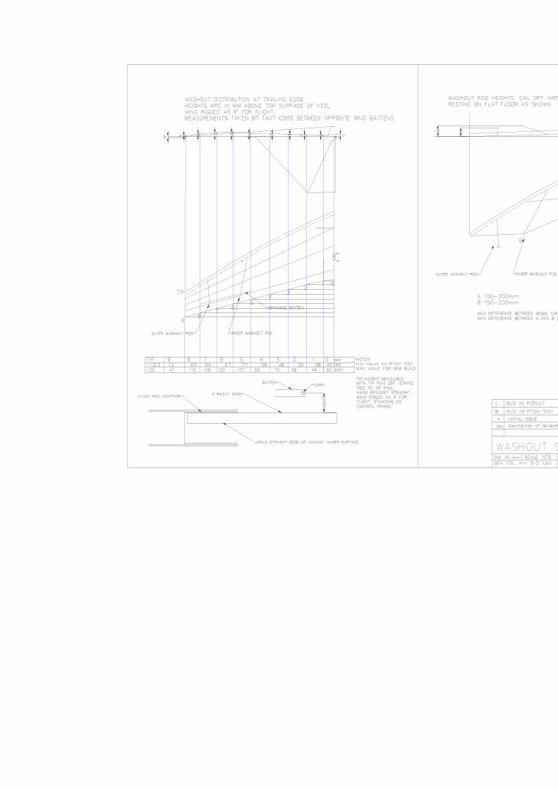
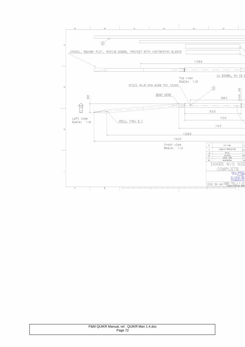
P&M QUIKR Manual, ref. QUIKR Man 1.4.doc Page 72
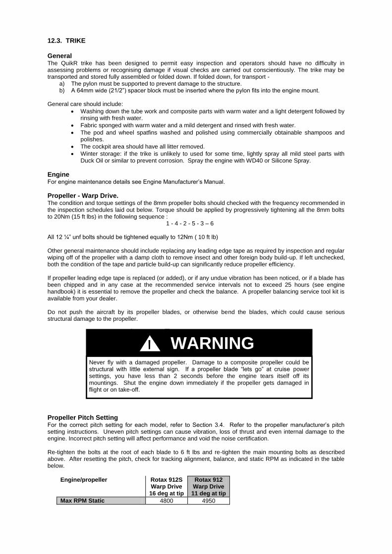
12.3. TRIKE General The QuikR trike has been designed to permit easy inspection and operators should have no difficulty in assessing problems or recognising damage if visual checks are carried out conscientiously. The trike may be transported and stored fully assembled or folded down. If folded down, for transport -
a) The pylon must be supported to prevent damage to the structure. b) A 64mm wide (21/2”) spacer block must be inserted where the pylon fits into the engine mount.
General care should include:
Washing down the tube work and composite parts with warm water and a light detergent followed by rinsing with fresh water.
Fabric sponged with warm water and a mild detergent and rinsed with fresh water.
The pod and wheel spatfins washed and polished using commercially obtainable shampoos and polishes.
The cockpit area should have all litter removed.
Winter storage: if the trike is unlikely to used for some time, lightly spray all mild steel parts with Duck Oil or similar to prevent corrosion. Spray the engine with WD40 or Silicone Spray.
Engine For engine maintenance details see Engine Manufacturer’s Manual.
Propeller - Warp Drive. The condition and torque settings of the 8mm propeller bolts should checked with the frequency recommended in the inspection schedules laid out below. Torque should be applied by progressively tightening all the 8mm bolts to 20Nm (15 ft lbs) in the following sequence : 1 - 4 - 2 - 5 - 3 – 6 All 12 ¼” unf bolts should be tightened equally to 12Nm ( 10 ft lb)
Other general maintenance should include replacing any leading edge tape as required by inspection and regular wiping off of the propeller with a damp cloth to remove insect and other foreign body build-up. If left unchecked, both the condition of the tape and particle build-up can significantly reduce propeller efficiency. If propeller leading edge tape is replaced (or added), or if any undue vibration has been noticed, or if a blade has been chipped and in any case at the recommended service intervals not to exceed 25 hours (see engine handbook) it is essential to remove the propeller and check the balance. A propeller balancing service tool kit is available from your dealer. Do not push the aircraft by its propeller blades, or otherwise bend the blades, which could cause serious structural damage to the propeller.
Propeller Pitch Setting For the correct pitch setting for each model, refer to Section 3.4. Refer to the propeller manufacturer’s pitch setting instructions. Uneven pitch settings can cause vibration, loss of thrust and even internal damage to the engine. Incorrect pitch setting will affect performance and void the noise certification. Re-tighten the bolts at the root of each blade to 6 ft lbs and re-tighten the main mounting bolts as described above. After resetting the pitch, check for tracking alignment, balance, and static RPM as indicated in the table below.
Engine/propeller Rotax 912S Warp Drive
16 deg at tip
Rotax 912 Warp Drive
11 deg at tip
Max RPM Static 4800 4950
Never fly with a damaged propeller. Damage to a composite propeller could be structural with little external sign. If a propeller blade “lets go” at cruise power settings, you have less than 2 seconds before the engine tears itself off its mountings. Shut the engine down immediately if the propeller gets damaged in flight or on take-off.
WARNING !
P&M Aviation QuikR Manual, QuikR1.4doc Page 74
Rigging System The gas strut is normally maintenance-free, but lubricate pivots occasionally. Do not subject to side-loads.
12.4. LUBRICATION
Trike The rear steering bar, foot throttle, hand throttle and choke lever pivots should be lubricated with machine oil weekly. Lubricate the rear suspension sliders with grease as in the following schedule. To do this you will need to dismantle each suspension leg in turn as follows: 1. Remove wing from trike & place a jack under the keel towards the rear using soft wood to prevent damage. 2. Lift the trike until the weight is just off 1 wheel and support it so that the trike cannot topple when the
suspension leg is dismantled, if possible tie the pylon up to a roof beam. 3. Disconnect bolt attaching lower suspension leg attachment eye, remove 2 socket screws near top of
suspension leg. 4. Withdraw the lower suspension leg, leaving the top section attached to the trike. 5. Loosen the locknut at the top of the upper suspension rod & remove the upper suspension rod using a tommy
bar to unscrew it. 6. Apply grease liberally to the sliders. 7. Reassemble in the reverse order, use Loctite 221 engineering adhesive on the upper suspension rod threads
and locknut and also on the two socket head screws. 8. Repeat the operation on the other leg.
All other bearings are life sealed and require no additional lubrication.
Make sure the aircraft is properly secured and clear of persons and animals before running this test. See Section 1.8. PREPARATION FOR SAFE MICROLIGHT/ MICROLIGHT AIRCRAFT OPERATION, Special Hazards, “Running Up and Testing an Engine on the Ground”.
When dismantling the suspension legs to lubricate the sliders it is essential that the trike is supported to ensure that it cannot topple over. Failure to do so could result in injury or death.
Gas under high pressure. Do not attempt to pierce, re-pressurise or incinerate.
It is essential that when re-assembling the suspension legs as in 10 above, you use Loctite 221 as indicated. It is better to use too much and wipe away any excess than to use too little, so apply it liberally to ensure that all the applicable threaded area is coated. Follow the instructions on the Loctite container. Failure to carry out this procedure could result in the undercarriage failing leading to injury or death.
WARNING !
WARNING !
WARNING !
WARNING !
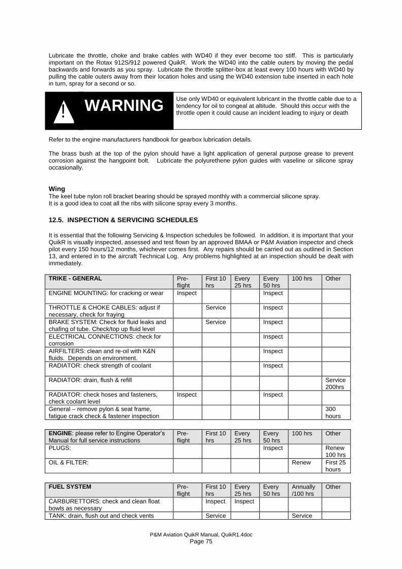
P&M Aviation QuikR Manual, QuikR1.4doc Page 75
Lubricate the throttle, choke and brake cables with WD40 if they ever become too stiff. This is particularly important on the Rotax 912S/912 powered QuikR. Work the WD40 into the cable outers by moving the pedal backwards and forwards as you spray. Lubricate the throttle splitter-box at least every 100 hours with WD40 by pulling the cable outers away from their location holes and using the WD40 extension tube inserted in each hole in turn, spray for a second or so. Refer to the engine manufacturers handbook for gearbox lubrication details. The brass bush at the top of the pylon should have a light application of general purpose grease to prevent corrosion against the hangpoint bolt. Lubricate the polyurethene pylon guides with vaseline or silicone spray occasionally.
Wing
The keel tube nylon roll bracket bearing should be sprayed monthly with a commercial silicone spray. It is a good idea to coat all the ribs with silicone spray every 3 months.
12.5. INSPECTION & SERVICING SCHEDULES It is essential that the following Servicing & Inspection schedules be followed. In addition, it is important that your QuikR is visually inspected, assessed and test flown by an approved BMAA or P&M Aviation inspector and check pilot every 150 hours/12 months, whichever comes first. Any repairs should be carried out as outlined in Section 13, and entered in to the aircraft Technical Log. Any problems highlighted at an inspection should be dealt with immediately. TRIKE - GENERAL Pre-
flight First 10 hrs
Every 25 hrs
Every 50 hrs
100 hrs Other
ENGINE MOUNTING: for cracking or wear Inspect
Inspect
THROTTLE & CHOKE CABLES: adjust if necessary, check for fraying
Service Inspect
BRAKE SYSTEM: Check for fluid leaks and chafing of tube. Check/top up fluid level
Service Inspect
ELECTRICAL CONNECTIONS: check for corrosion
Inspect
AIRFILTERS: clean and re-oil with K&N fluids. Depends on environment.
Inspect
RADIATOR: check strength of coolant
Inspect
RADIATOR: drain, flush & refill Service 200hrs
RADIATOR: check hoses and fasteners, check coolant level
Inspect Inspect
General – remove pylon & seat frame, fatigue crack check & fastener inspection
300 hours
ENGINE: please refer to Engine Operator’s
Manual for full service instructions Pre-flight
First 10 hrs
Every 25 hrs
Every 50 hrs
100 hrs Other
PLUGS: Inspect Renew 100 hrs
OIL & FILTER: Renew
First 25 hours
FUEL SYSTEM Pre-
flight First 10 hrs
Every 25 hrs
Every 50 hrs
Annually /100 hrs
Other
CARBURETTORS: check and clean float bowls as necessary
Inspect Inspect
TANK: drain, flush out and check vents Service Service
Use only WD40 or equivalent lubricant in the throttle cable due to a tendency for oil to congeal at altitude. Should this occur with the throttle open it could cause an incident leading to injury or death
WARNING !

P&M Aviation QuikR Manual, QuikR1.4doc Page 76
FUEL FILTERS: check for contamination, change
Inspect Service
FUEL LINES: check for cracking or leaks, check torque on all connectors and clips
Inspect Inspect
TRANSMISSION Pre-flight
First 10 hrs
Every 25 hrs
Every 50 hrs
Annually /100 hrs
Other
PROPELLER: check for cracks & delamination
Inspect
PROP BOLTS: check state of bolts & torque Inspect Service Service
GEARBOX BEARING: check for play
Inspect
TRIKE FRAME Pre-
flight First 10 hrs
Every 25 hrs
Every 50 hrs
Annually /100 hrs
Other
PYLON TUBE: check for cracks, bends & fatigue (Also after every hard landing)
Inspect
PYLON TUBE: Check bottom pivot and bolt
Inspect
PYLON TUBE: Check fairing fasteners
Inspect
BASE TUBE: check for cracks, bends & fatigue (Also after every hard landing)
Inspect
FRONT STRUT: check for cracks, bends & fatigue (Also after every hard landing)
Inspect
SEAT FRAME: check for fatigue and bends
Inspect
HANG POINT
Inspect Inspect
HANG BOLT: check condition of bolt & Lanyard
Inspect
PYLON BUSH: check security
Inspect
UNDERCARRIAGE Pre-flight
First 10 hrs
Every 25 hrs
Every 50 hrs
Annually /100 hrs
Other
TYRES: check condition of treads & sidewalls
Inspect
TYRE PRESSURES: 22psi
Inspect
FRONT FORK RUBBERS: check ride height and adjust as necessary
Inspect
FRONT FORKS: check for damage
Inspect Inspect
FRONT FORK BEARINGS AND HOLDERS: check for play in steering head
Inspect
BRAKES: check shoes/pads
Inspect
BRAKES: Check for chafing of cables or nylon tubing and pad wear, check brake fluid level and check for leaks.
Inspect
WHEEL BEARINGS: check seals and general condition
Inspect
WHEEL HUBS: check for damage and wear after every heavy landing
Inspect
REAR STRUTS: check rose joint security
Inspect
REAR STRUTS: Grease sliders
Service 200 hrs
WISHBONES: check for damage, check security of fasteners
Inspect
ELECTRIC TRIM SYSTEM Pre-flight
First 10 hrs
Every 25 hrs
Every 50 hrs
Annually /100 hrs
Other
Connected, operates correctly, full and free movement of controls, trim display
check
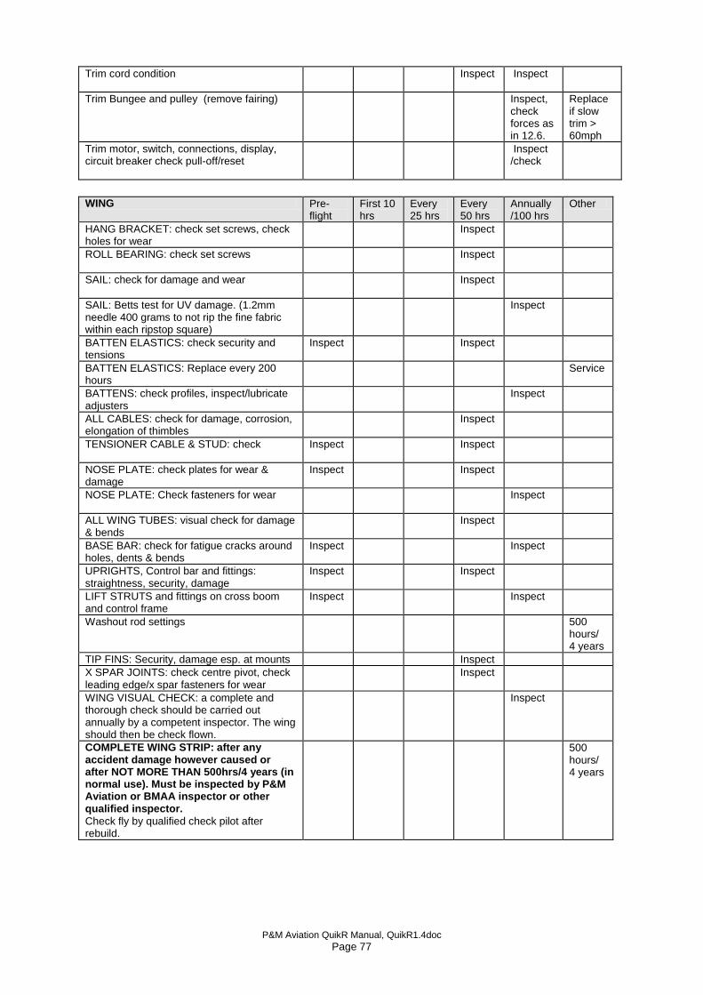
P&M Aviation QuikR Manual, QuikR1.4doc Page 77
Trim cord condition Inspect Inspect
Trim Bungee and pulley (remove fairing) Inspect, check forces as in 12.6.
Replace if slow trim > 60mph
Trim motor, switch, connections, display, circuit breaker check pull-off/reset
Inspect /check
WING Pre-
flight First 10 hrs
Every 25 hrs
Every 50 hrs
Annually /100 hrs
Other
HANG BRACKET: check set screws, check holes for wear
Inspect
ROLL BEARING: check set screws
Inspect
SAIL: check for damage and wear
Inspect
SAIL: Betts test for UV damage. (1.2mm needle 400 grams to not rip the fine fabric within each ripstop square)
Inspect
BATTEN ELASTICS: check security and tensions
Inspect Inspect
BATTEN ELASTICS: Replace every 200 hours
Service
BATTENS: check profiles, inspect/lubricate adjusters
Inspect
ALL CABLES: check for damage, corrosion, elongation of thimbles
Inspect
TENSIONER CABLE & STUD: check
Inspect Inspect
NOSE PLATE: check plates for wear & damage
Inspect Inspect
NOSE PLATE: Check fasteners for wear
Inspect
ALL WING TUBES: visual check for damage & bends
Inspect
BASE BAR: check for fatigue cracks around holes, dents & bends
Inspect Inspect
UPRIGHTS, Control bar and fittings: straightness, security, damage
Inspect Inspect
LIFT STRUTS and fittings on cross boom and control frame
Inspect Inspect
Washout rod settings
500 hours/ 4 years
TIP FINS: Security, damage esp. at mounts Inspect
X SPAR JOINTS: check centre pivot, check leading edge/x spar fasteners for wear
Inspect
WING VISUAL CHECK: a complete and thorough check should be carried out annually by a competent inspector. The wing should then be check flown.
Inspect
COMPLETE WING STRIP: after any accident damage however caused or after NOT MORE THAN 500hrs/4 years (in normal use). Must be inspected by P&M Aviation or BMAA inspector or other qualified inspector.
Check fly by qualified check pilot after rebuild.
500 hours/ 4 years
P&M Aviation QuikR Manual, QuikR1.4doc Page 78
Amended Betts test value 13/8/08
12.6. INSPECTION CRITERIA: General In the main, the safe working life of the structural components of the P&M QuikR is dictated by the environment in which the aircraft is used and the care taken during day to day operations. Inspection, therefore, is an essential tool in deciding the continued use of most components. Some parts such as bolts are not amenable to fatigue crack inspection, therefore it is more practical to replace them. Nyloc nuts in primary structure should not be used more than once. At least one complete thread must protrude. Split pins should only be used once. Unless otherwise specified, airframe bolts should be tightened so as to remove all free play without causing distortion of the parts (e.g. ovalising or denting tubes). Sail & Stitching inspection:
The Polyester sailcloth is subject to degradation by UV light. Spun PTFE Stitches can be weakened by abrasion. The Bettsometer test gives a good indication of the capability of the sailcloth to transfer load at a stitch hole. The sail should be checked in the root, midspan and tip areas of single thickness main body sailcloth. Enough tension should be applied to the sailcloth to prevent it puckering at the test needle. The sail is of ripstop construction and the Bettsometer test is applied to the fine fabric within each ripstop square. The sailcloth should be tested to 400 grammes with a 1.2mm needle in the warp direction (spanwise), loading the fine fabric, not the rip-stop thread. The fine fabric must not rip at 400gr load. Bolts:
Finish: Not corroded Wear: Not above .025mm (.001”) Must not be bent or have damaged threads. Rigging Cables:
No corrosion, broken strands, kinking of cable or thimbles, Or any sign of movement at a swage. (Plastic boots must be slid back to inspect swages.) Any instance of swage movement should be reported to the Factory. Major airframe tubes:
1) Straightness – maximum tolerance Length/600, for leading edge outers, Length/500. Straightness is measured from the point of maximum bend to a straight line running from each end of the tube. If both tubes have a perceptible set, leading edge outers should be replaced in pairs. Leading edges must NEVER be turned round or straightened. 2)No Fretting or corrosion, e.g. between sleeves. 3) No dents deeper than 0.2mm 4) Any scoring up to 0.1mm deep should be blended out, finishing with 1200 grit abrasive paper and coating in clear lacquer. 5) No visible cracks are permissible. Hang Bracket and control frame top knuckles:
The hang bracket must be inspected for cracks, distortion and wear, particularly at the Hangbolt hole. Maximum diameter for the hangbolt hole is 10.7mm. The hangbolt is NOT intended to rotate in the bracket, and should be tightened securely by hand. The control frame pivot bolts must be secure yet allow easy movement. The control frame uprights must be straight, the tube ends must not be distorted and the end fittings and rivets must be secure.

P&M Aviation QuikR Manual, QuikR1.4doc Page 79
Amended Bettsometer test procedure and values 13/8/08
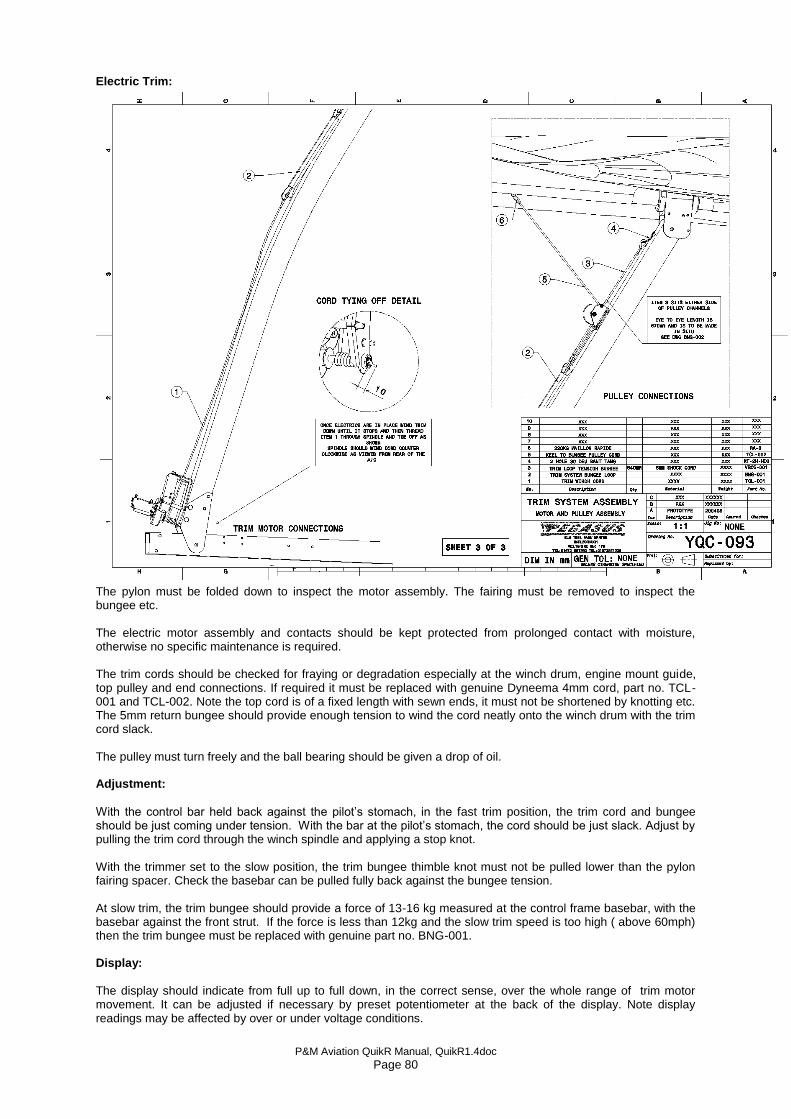
P&M Aviation QuikR Manual, QuikR1.4doc Page 80
Electric Trim:
The pylon must be folded down to inspect the motor assembly. The fairing must be removed to inspect the bungee etc. The electric motor assembly and contacts should be kept protected from prolonged contact with moisture, otherwise no specific maintenance is required. The trim cords should be checked for fraying or degradation especially at the winch drum, engine mount guide, top pulley and end connections. If required it must be replaced with genuine Dyneema 4mm cord, part no. TCL-001 and TCL-002. Note the top cord is of a fixed length with sewn ends, it must not be shortened by knotting etc. The 5mm return bungee should provide enough tension to wind the cord neatly onto the winch drum with the trim cord slack. The pulley must turn freely and the ball bearing should be given a drop of oil. Adjustment:
With the control bar held back against the pilot’s stomach, in the fast trim position, the trim cord and bungee should be just coming under tension. With the bar at the pilot’s stomach, the cord should be just slack. Adjust by pulling the trim cord through the winch spindle and applying a stop knot. With the trimmer set to the slow position, the trim bungee thimble knot must not be pulled lower than the pylon fairing spacer. Check the basebar can be pulled fully back against the bungee tension. At slow trim, the trim bungee should provide a force of 13-16 kg measured at the control frame basebar, with the basebar against the front strut. If the force is less than 12kg and the slow trim speed is too high ( above 60mph) then the trim bungee must be replaced with genuine part no. BNG-001. Display:
The display should indicate from full up to full down, in the correct sense, over the whole range of trim motor movement. It can be adjusted if necessary by preset potentiometer at the back of the display. Note display readings may be affected by over or under voltage conditions.
P&M Aviation QuikR Manual, QuikR1.4doc Page 81
Electrical protection:
The system is protected by a 5A push on/pull off circuit breaker. This should not operate in any normal condition of use. If it operates, leave for 2 minutes before attempting a reset. If it operates again, the motor system, wiring and limit switches must be checked. The CB can be manually pulled OFF if required. Note:
The main charging fuse from the regulator to the battery should be 30A when electric trim is fitted.
The main fuse from the master switch to the main electrical bus should be 20A when electric trim is fitted. 12.7 FATIGUE LIFE:
At maximum intervals of 500 hours the following components should be inspected for signs of fatigue crack damage, particularly at holes, notches and joints. The parts should be inspected in detail by a qualified inspector using dye penetrant, radiographic, or visual high magnification methods The ideal time to do the fatigue inspections is during the wing strip-down (see servicing schedule). If no cracks/damage is found the parts may be returned to service. Leading edges Keel Pylon Seat frame Trike base tube Front strut & channels Control frame upright top and bottom fittings Lift strut end fittings. Cross boom lift strap fabrications. Control bar end holes. Control bar end knuckles. Leading edge/crossboom channel holes in the tube. Leading edge outer at the sleeve edges. Keel roll bearing holes. Trike pylon top & bottom fittings - bush must not rotate, no cracks around the bush. Trike pylon top& bottom end corners. Trike basetube at seat frame bracket holes. Trike basetube at rear steering pivot holes. Seat frame holes. Any instance of fatigue cracking must be reported to the Factory. No cracked parts may be returned to service unless there is a P&M approved modification to recover the part ( e.g. drilling out and bush insertion). Unserviceable parts must be made unusable, e.g. by cutting up. For the following small items, inspection is not practical and so replacement is strongly recommended at the following times: Hang bolt 250 hours.
It is vitally important that the lifing & NDT of all components is strictly observed, or serious injury or death could occur.
WARNING !
P&M Aviation QuikR Manual, QuikR1.4doc Page 82
13. REPAIRS
13.1. WING
Repairs must be inspected by a BMAA or P&M Aviation Ltd approved inspector and signed off in the technical log.
Sail repairs are only to be undertaken by a P&M Aviation approved sail loft.
Airframe repairs are to be by replacement only.
Replacement parts must be obtained from P&M Aviation Ltd or a P&M Aviation appointed agency.
Bent aluminium tubes must never be straightened, always replaced.
Frayed cables and cables with damaged or twisted thimbles must be replaced. 13.2. TRIKE Repairs must be inspected and signed off as above.
Repairs to primary structure by replacement only.
Replacement parts must be obtained from P&M Aviation Ltd or a P&M Aviation appointed agency.
Bent aluminium tubes must never be straightened, always replaced.
Frayed cables and cables with damaged or twisted thimbles must be replaced. Repairs to composite structures must first be assessed by P&M Aviation Ltd or a P&M Aviation approved composites facility.
The P&M Aviation QuikR airframe is deceptively simple, but like all aircraft requires skilled and qualified attention. We do not recommend self repair or re-assembly by other than P&M Aviation or P&M Aviation nominated repair agents. No replacement parts should be fitted unless they are factory supplied and identified. All replacements & servicing should be entered into the aircraft technical log book supplied and signed off by a qualified inspector. Incorrect servicing, maintenance or fitting of parts could result in injury or death.
WARNING !
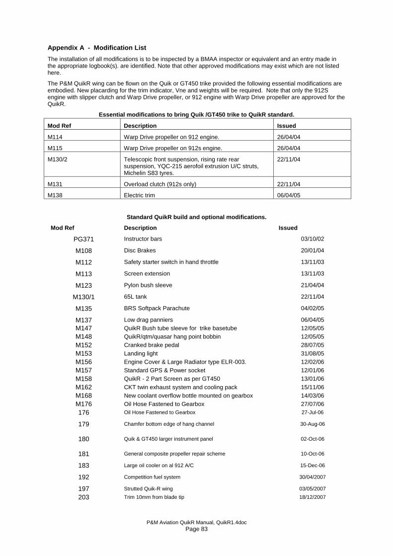
P&M Aviation QuikR Manual, QuikR1.4doc Page 83
Appendix A - Modification List
The installation of all modifications is to be inspected by a BMAA inspector or equivalent and an entry made in the appropriate logbook(s). are identified. Note that other approved modifications may exist which are not listed here.
The P&M QuikR wing can be flown on the Quik or GT450 trike provided the following essential modifications are embodied. New placarding for the trim indicator, Vne and weights will be required. Note that only the 912S engine with slipper clutch and Warp Drive propeller, or 912 engine with Warp Drive propeller are approved for the QuikR.
Essential modifications to bring Quik /GT450 trike to QuikR standard.
Mod Ref Description Issued
M114 Warp Drive propeller on 912 engine. 26/04/04
M115 Warp Drive propeller on 912s engine. 26/04/04
M130/2 Telescopic front suspension, rising rate rear suspension, YQC-215 aerofoil extrusion U/C struts, Michelin S83 tyres.
22/11/04
M131 Overload clutch (912s only) 22/11/04
M138 Electric trim 06/04/05
Standard QuikR build and optional modifications.
Mod Ref Description Issued
PG371 Instructor bars 03/10/02
M108 Disc Brakes 20/01/04
M112 Safety starter switch in hand throttle 13/11/03
M113 Screen extension 13/11/03
M123 Pylon bush sleeve 21/04/04
M130/1 65L tank 22/11/04
M135 BRS Softpack Parachute 04/02/05
M137 Low drag panniers 06/04/05
M147 QuikR Bush tube sleeve for trike basetube 12/05/05
M148 QuikR/qtm/quasar hang point bobbin 12/05/05
M152 Cranked brake pedal 28/07/05
M153 Landing light 31/08/05
M156 Engine Cover & Large Radiator type ELR-003. 12/02/06
M157 Standard GPS & Power socket 12/01/06
M158 QuikR - 2 Part Screen as per GT450 13/01/06
M162 CKT twin exhaust system and cooling pack 15/11/06
M168 New coolant overflow bottle mounted on gearbox 14/03/06
M176 Oil Hose Fastened to Gearbox 27/07/06
176 Oil Hose Fastened to Gearbox 27-Jul-06
179 Chamfer bottom edge of hang channel 30-Aug-06
180 Quik & GT450 larger instrument panel 02-Oct-06
181 General composite propeller repair scheme 10-Oct-06
183 Large oil cooler on al 912 A/C 15-Dec-06
192 Competition fuel system 30/04/2007
197 Strutted Quik-R wing 03/05/2007
203 Trim 10mm from blade tip 18/12/2007

P&M Aviation QuikR Manual, QuikR1.4doc Page 84
204 webs on engine mount 21/01/2008
214 Competition fuel tank 19/05/2008
216 Cranked throttle pedal 06/08/2008
217 Stoneguard 06/08/2008
218 Fitting of Enigma instrument 21/08/2008
220 PX10T leading edge material 21/08/2008
221 Rear hang point 08/10/2008
222 Batten over centre levers 08/10/2008
223 Sail repair scheme 14/10/2008
224 Avio position light/strobe 15/10/2008
225 Trim Pot 13/01/2009
226 Rotax 912 engine on QuikR 05/05/2009
229 Keel pocket reinforcing 01/06/2009
230 TE Buzz CFRP strip 07/06/2009
231 Dash Radio/Transponder/ELT 13/07/2009
232 Seat Belt Protection Sleeve 19/08/2009
233 Quik Tip Plug Fastener 18/11/2009
234 Hand Controls - Qtm/Quik Range 10/12/2009
235 YTZ-14S Battery 10/12/2009
236 Technora Strips 30/06/2010
244 Oil and Coolant Thermostat 12/01/2011
245 Fuel Pressure Gauge 10/09/2010
247 Nylon Washers For Wings 26/01/2011
248 Throttle splitter box assembly 23/03/2012
249 Super B battery 13/05/2011
250 TNF-215UV QuikR sailcloth 16/05/2011
251 Windscreen washer 15/06/2011
252 STARS system on QuikR 07/06/2011
256 Black Max wheels Quik 13/09/2011
259 Axle spacer 19/03/2012
262 Steering Head Plate Redesign 17/04/2012
264 Explorer Nosewheel Axle 18/06/2012
265 Hand throttle lever Qtm/Quik 22/06/2012
269 remote oil press sender 11/09/2012
272 Facet Boost Pump 26/11/2014
273 Stainless steel training handle tubes 21/12/2013
275 Roll trimmer 17/07/2013
276 Main subframe Stiffen Top Plate 10/02/2014
277 Slotted wingtip adjuster 27/02/2014
279 Quik R Sail u/surf vents 01/04/2014
281 GTR and QuikR no fins 04/06/2014
282 Fournales shocks 23/06/2014
284 Explorer steering stop material 31/07/2014
285 Hangbolt anti rotation 22/09/2014
286 200mm Spinner 24/11/2014
291 Modified throttle cable bracket 22/06/2015
292 CT fuel purge line 22/06/2015
293 Q2 wing keel sleeve 14/07/2015
294 GT450 G-CFIM parachute step 15/09/2015
296 Vhf antenna routing 07-Oct-15
297 Underseat carry bags 09-Dec-15
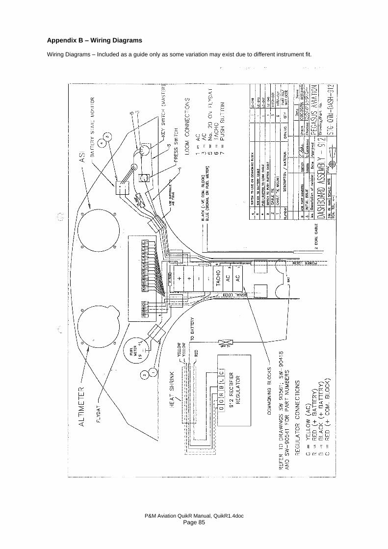
P&M Aviation QuikR Manual, QuikR1.4doc Page 85
Appendix B – Wiring Diagrams Wiring Diagrams – Included as a guide only as some variation may exist due to different instrument fit.
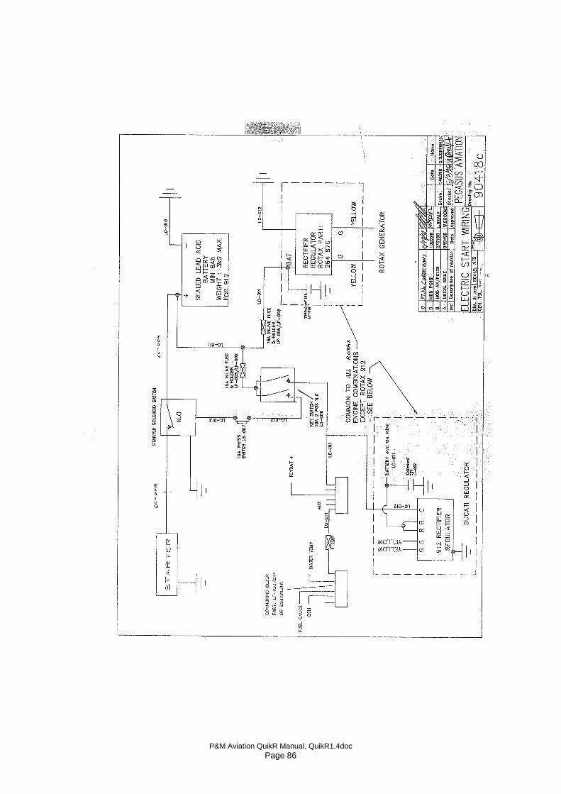
P&M Aviation QuikR Manual, QuikR1.4doc Page 86
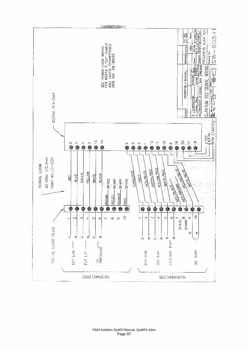
P&M Aviation QuikR Manual, QuikR1.4doc Page 87
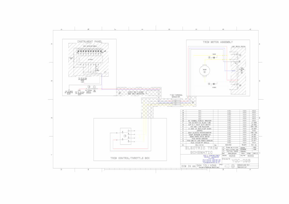
Appendix C, Modification M252 STARS stability trim and roll
system
QUIKR WITH
“STARS” MOD.
M252
Operator’s Manual Suppliment - Issue 1.0
P&M Aviation Ltd.

P&M Aviation QuikR Manual, QuikR1.4doc Page 91
TABLE OF CONTENTS PAGE 1. Introduction 3 2. Definition of modification 3 3. General description of STARS system 5 4. Inspection 7 5. Rigging the wing 8 6. Wing tuning 9 7. Emergency procedure 10
NOTICE
Modification M252 ( QuikR stars system) is intended as a factory fitted modification. This supplement must be attached to the QuikR operator’s handbook when mod M252 is incorporated.
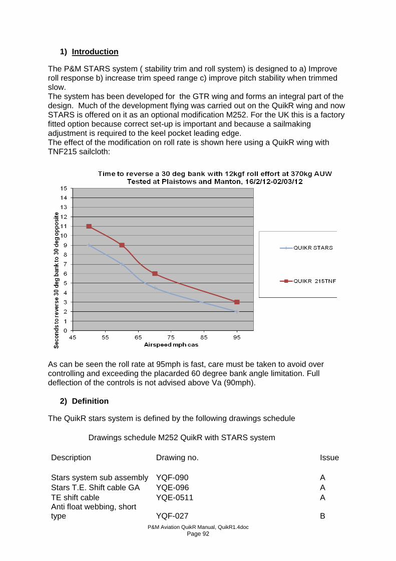
P&M Aviation QuikR Manual, QuikR1.4doc Page 92
1) Introduction
The P&M STARS system ( stability trim and roll system) is designed to a) Improve roll response b) increase trim speed range c) improve pitch stability when trimmed slow. The system has been developed for the GTR wing and forms an integral part of the design. Much of the development flying was carried out on the QuikR wing and now STARS is offered on it as an optional modification M252. For the UK this is a factory fitted option because correct set-up is important and because a sailmaking adjustment is required to the keel pocket leading edge. The effect of the modification on roll rate is shown here using a QuikR wing with TNF215 sailcloth:
As can be seen the roll rate at 95mph is fast, care must be taken to avoid over controlling and exceeding the placarded 60 degree bank angle limitation. Full deflection of the controls is not advised above Va (90mph).
2) Definition
The QuikR stars system is defined by the following drawings schedule
Drawings schedule M252 QuikR with STARS system
Description Drawing no. Issue
Stars system sub assembly YQF-090
A
Stars T.E. Shift cable GA YQE-096
A
TE shift cable YQE-0511
A Anti float webbing, short type YQF-027
B
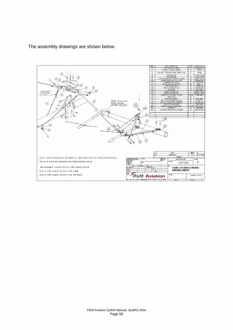
P&M Aviation QuikR Manual, QuikR1.4doc Page 93
The assembly drawings are shown below.
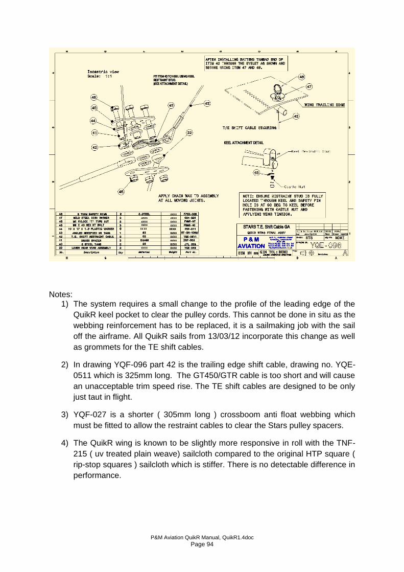
P&M Aviation QuikR Manual, QuikR1.4doc Page 94
Notes:
1) The system requires a small change to the profile of the leading edge of the
QuikR keel pocket to clear the pulley cords. This cannot be done in situ as the
webbing reinforcement has to be replaced, it is a sailmaking job with the sail
off the airframe. All QuikR sails from 13/03/12 incorporate this change as well
as grommets for the TE shift cables.
2) In drawing YQF-096 part 42 is the trailing edge shift cable, drawing no. YQE-
0511 which is 325mm long. The GT450/GTR cable is too short and will cause
an unacceptable trim speed rise. The TE shift cables are designed to be only
just taut in flight.
3) YQF-027 is a shorter ( 305mm long ) crossboom anti float webbing which
must be fitted to allow the restraint cables to clear the Stars pulley spacers.
4) The QuikR wing is known to be slightly more responsive in roll with the TNF-
215 ( uv treated plain weave) sailcloth compared to the original HTP square (
rip-stop squares ) sailcloth which is stiffer. There is no detectable difference in
performance.
P&M Aviation QuikR Manual, QuikR1.4doc Page 95
3. General description of the STARS system. Flexwings generally have light handling at high speed but become progressively more stable and heavier to manoeuvre at lower speeds. The Stars system works with the trimmer so that the more nose-up (slow) trim is applied, the more the STARS system works to increase roll response. The way it works is shown schematically below. Pitch axis Fast trim: In the fast trim condition the whole system is slack and has no effect on the wing. The wing trims fast because the hangpoint is set to provide the maximum hands-off trim speed (approximately 95mph). The wing is shown in the fast trim condition in figs 3 (side view) and 4 (rear view), where the sail is shown with minimum washout. The minimum washout is held in by the washout rod system so as to produce positive pitch stability. In the fast trim condition the STARS system must be set so that it becomes just taut as the control bar approaches the pilot’s stomach. Slow trim: Referring to fig. 1, In the slow trim condition the trim motor 1 pulls the trim spring (bungee) 2 and tightens cord 3 which is attached to the keel by pulley 4. At pulley 4 the cord splits into two, one running to each wing around pulleys 5. The cord continues into position 6 then around pulley 7 which is attached to the outboard washout rod 9. The cord continues from pulley 7 to position 11 and is attached to the leading edge post 10. Since the washout rods are connected to the leading edge by a universal joint and are prevented from moving inboard by cable 8, tension in the trim cord 3 causes both washout rods to be pulled upwards, so increasing washout. Increased washout improves pitch stability and also prevents the possibility of tip stalling. Tension in cord 3 also applies a direct mechanical nose-up pitch relative to the trike. The combined effect is to slow the trim speed and increase pitch stability.
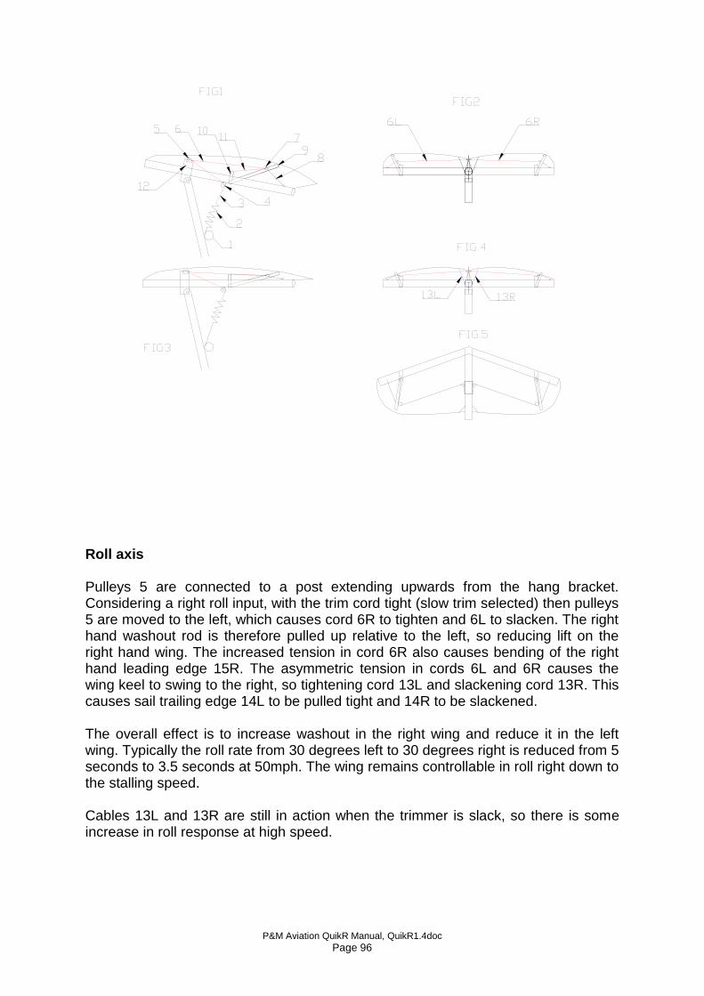
P&M Aviation QuikR Manual, QuikR1.4doc Page 96
Roll axis Pulleys 5 are connected to a post extending upwards from the hang bracket. Considering a right roll input, with the trim cord tight (slow trim selected) then pulleys 5 are moved to the left, which causes cord 6R to tighten and 6L to slacken. The right hand washout rod is therefore pulled up relative to the left, so reducing lift on the right hand wing. The increased tension in cord 6R also causes bending of the right hand leading edge 15R. The asymmetric tension in cords 6L and 6R causes the wing keel to swing to the right, so tightening cord 13L and slackening cord 13R. This causes sail trailing edge 14L to be pulled tight and 14R to be slackened. The overall effect is to increase washout in the right wing and reduce it in the left wing. Typically the roll rate from 30 degrees left to 30 degrees right is reduced from 5 seconds to 3.5 seconds at 50mph. The wing remains controllable in roll right down to the stalling speed. Cables 13L and 13R are still in action when the trimmer is slack, so there is some increase in roll response at high speed.
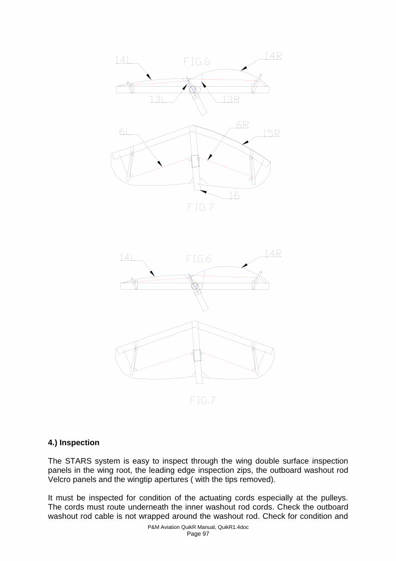
P&M Aviation QuikR Manual, QuikR1.4doc Page 97
4.) Inspection The STARS system is easy to inspect through the wing double surface inspection panels in the wing root, the leading edge inspection zips, the outboard washout rod Velcro panels and the wingtip apertures ( with the tips removed). It must be inspected for condition of the actuating cords especially at the pulleys. The cords must route underneath the inner washout rod cords. Check the outboard washout rod cable is not wrapped around the washout rod. Check for condition and
P&M Aviation QuikR Manual, QuikR1.4doc Page 98
security of the pulleys. No lubrication is required as marine pulleys with delrin ballraces are used. The STARS bracket above the hang bracket has a rubbing strip which acts on a rubbing strip on the sail – check for rubbing/chafing damage. There are adjustment loops provided in the STARS cords each side of the keel pocket. The cords should be adjusted to be just taut when the trimmer is off. Assymmetric adjustment of the cords can be used for trimming out a low speed turn. The cords are all low stretch Dyneema with a polyester braided covering. Those inside the wing are 3mm, the cord at pulley 4 on the keel is 3mm and the cords on the trike must be 4mm. Replace in the event of fraying or abrasion. The STARS system should be adjusted so that the trim system, when set fully fast, becomes tight just before the control bar reaches the pilot’s stomach. The STARS system is also used to adjust turns which only appear at low speed. See tuning section. 5. Rigging the wing Follow the existing QuikR manual rigging instructions and add the following additional inspections referring to drawing YQF-090:
1) Ensure all cord runs are straight, in particular that there is a straight run of the STARS cords from the outer washout rod pulleys to the pulleys mounted on the keel plates.
2) Check that the outer washout rod to tip cable and bungee is lying straight and has not become wrapped around the washout rod.
3) Inspect for abrasion or mouse damage.
P&M Aviation QuikR Manual, QuikR1.4doc Page 99
Preflight Inspection
7. PRE-FLIGHT INSPECTION6.1. WING Action
Done?
Nose catch secure, locking washer fitted
Leading-edge spar undented, shape correct
Crossboom junction secure, restraint webbing ok
Sail secure on tip, tip settings correct
Washout rods fully deployed
Upper strut connections secure, wingnuts and safety rings in position
Crossboom tensioner secure & not twisted, safety pin fitted
Keel pocket and rocker components undamaged
Hang-point secure and freely rotating
Control frame wingnuts and safety rings on basebar and lower strut fittings.
Trimmer shackle connected to trike
Trimmer functioning properly, STARS cords condition, cords routed correctly to outer washout rods.
Cables to control frame secure
Condition and security of composite flexible ribs
All other ribs secure, elastics fitted correctly & undamaged
Nose rib and nose cone secure and correctly fitted
Tip fins secure and correctly fitted
Rigging tool detached and stowed.
Inspection zippers and undersurface Velcro secured
6.) WING TUNING In addition to the existing QuikR manual section 11, the following applies: With the STARS system, it has been found best to move the tip adjuster plugs symmetrically, only for trim speed adjustment. Instead of adjusting the tips asymmetrically, the STARS cords can be used to tune out low speed turns and the wing rib reflex technique used for high speed turns. Turns: Example: The aircraft turns right especially at low speed. The trim speed is correct.
P&M Aviation QuikR Manual, QuikR1.4doc Page 100
Solution: In this case use asymmetric tension in the STARS cords. Tighten the left hand cord slightly using the adjustment loop by the left hand side of the keel pocket. Check fly and adjust until the turn is removed. The aircraft flies straight at low speeds but develops a turn to the LEFT at high speed. Solution – apply a small amount of reflex ( 10mm ) to ribs 7 & 8 on the LEFT wing ( the side which is dropping). “Tab” effect will cause the left wing to develop more lift at high speed which will straighten out the turn. Trim speed. When the sail is very new the fast trim speed may be around 85mph. This tends to increase over the first 10 hours or so of operation as the sail beds in. The optimum for the QuikR on the front hang point is 95mph, not over 100mph. Trim speed at the fast trim setting. Check the trim system is going slack when the bar is pulled in and the trimmer set fully fast. If the trim speed is still too slow, turn both tip adjusters down. 3 divisions down = approximately 4mph trim speed rise. If the trim speed is still too slow, the tip rib camber can be increased within the limits set on the batten plan. If the trim speed is too high, do the opposite i.e. turn both tips UP and reduce tip camber as well if necessary. Trim speed at the slow trim setting The trimmer cord should be set so that it is just slack with the bar pulled fully in to the pilot’s stomach and the trimmer set fully fast. Typical trim speed range should then be 95 – 50 solo, 95 – 55 dual. Always push the bar to the required slow trim speed then take off the trim pressure using the trimmer 7.)Emergency procedure - failure of one Stars system cord. Properly maintained, failure of any part of the system (e.g. one washout rod cord ) is most unlikely. However, if it should occur with slow trim set, a noticeable turn bias will result. If a turn suddenly develops in the wing, particularly when trimmed slow on the approach, apply roll control against the turn and set up a climbing bank in the opposite direction. Select trim towards the fast position and the turn will steadily diminish. Then an approach can be made at normal speeds, accepting the out of trim pitch force.
P&M Aviation QuikR Manual, QuikR1.4doc Page 101
Appendix D, Modification M275, Roll Trimmer
Roll Trimmer for QuikR ( STARS equipped) and GTR flexwings. General Both the QuikR and GTR use the STARS system ( mod M252) which operates the outer washout rods. In roll, the washout rods are operated asymmetrically to aid roll response, and when slow pitch trim is selected, both washout rods are pulled upwards, increasing pitch stability and avoiding tip stalling. The roll trimmer ( mod. M275) works on the RH STARS cord, so that tensioning it causes a RH turn by pulling up the RH washout rod, “tight for right, loose for left”. Using the roll trim, any annoying hands-off turns can simply be trimmed out in flight. See drawing YQE-0901 issue A for details. Tuning Since the roll trimmer operates on the RH wing only, the wing is tuned to have a MILD LH turn when the RH STARS cord is slack. By tightening the RH STARS cord, a RH turn can be produced. By varying the tension in the RH STARS cord, the wing can be trimmed in flight to fly absolutely straight under all conditions of loading, speed and power. In general the QuikR and GTR tend to go left at high speed and power due to torque and P effect. Setting up The wing tip adjusters need only to be adjusted symmetrically, i.e. both UP to reduce trim speed and vice versa. With no load on the roll trim cord, the roll trim wheel friction should be set by adjusting the castle nut and split pin so that a force of 4 to 5kgf applied on the knob is sufficient to move it. If the aircraft is fully assembled and rigged for flight, Set the pitch trim on fully fast ( i.e. slack trim motor cord) and the control frame basebar held central in roll. If the wing is off the trike, position the hang bracket central with the wing nose down on a level surface. Adjustment of the STARS cords. There should be enough tension in the LH STARS cord to take out all the slack in the outer washout rod cable ( part 17 in the drawing). Adjust by using the loop and knot on the LH side of the keel pocket. The RH STARS cord should be set up so that with 2 turns of cord wrapped on the roll trim wheel, the tension is similar. The wheel should be set up so that clockwise rotation = tighter cord = right roll. Check Flight Smooth conditions are adviseable. Set trim for takeoff and ensure the roll trim is still set neutral ( 2 wraps on the wheel). Take off as normal, correct any turn by weight shift. Establish a mid range cruising speed ( typically 70 – 8o mph) and trim out in pitch. Ensure the nosewheel is straight. It should be possible to produce a steady right and left roll by using the trim wheel. Remember that a LH turn can only be produced by slackening the RH cord, if the roll trim cord becomes slack and the aircraft is still not turning left, land and adjust. If more LH turn is needed, land and tighten the LH STARS cord.
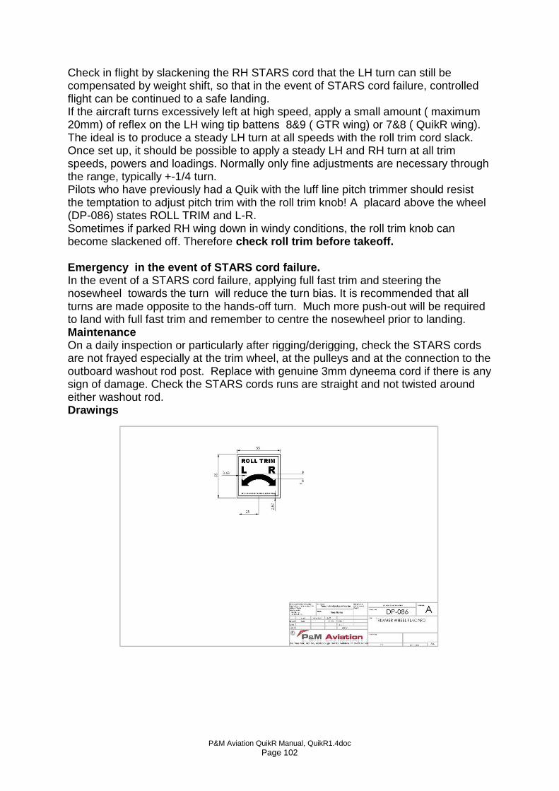
P&M Aviation QuikR Manual, QuikR1.4doc Page 102
Check in flight by slackening the RH STARS cord that the LH turn can still be compensated by weight shift, so that in the event of STARS cord failure, controlled flight can be continued to a safe landing. If the aircraft turns excessively left at high speed, apply a small amount ( maximum 20mm) of reflex on the LH wing tip battens 8&9 ( GTR wing) or 7&8 ( QuikR wing). The ideal is to produce a steady LH turn at all speeds with the roll trim cord slack. Once set up, it should be possible to apply a steady LH and RH turn at all trim speeds, powers and loadings. Normally only fine adjustments are necessary through the range, typically +-1/4 turn. Pilots who have previously had a Quik with the luff line pitch trimmer should resist the temptation to adjust pitch trim with the roll trim knob! A placard above the wheel (DP-086) states ROLL TRIM and L-R. Sometimes if parked RH wing down in windy conditions, the roll trim knob can become slackened off. Therefore check roll trim before takeoff. Emergency in the event of STARS cord failure. In the event of a STARS cord failure, applying full fast trim and steering the nosewheel towards the turn will reduce the turn bias. It is recommended that all turns are made opposite to the hands-off turn. Much more push-out will be required to land with full fast trim and remember to centre the nosewheel prior to landing. Maintenance On a daily inspection or particularly after rigging/derigging, check the STARS cords are not frayed especially at the trim wheel, at the pulleys and at the connection to the outboard washout rod post. Replace with genuine 3mm dyneema cord if there is any sign of damage. Check the STARS cords runs are straight and not twisted around either washout rod. Drawings
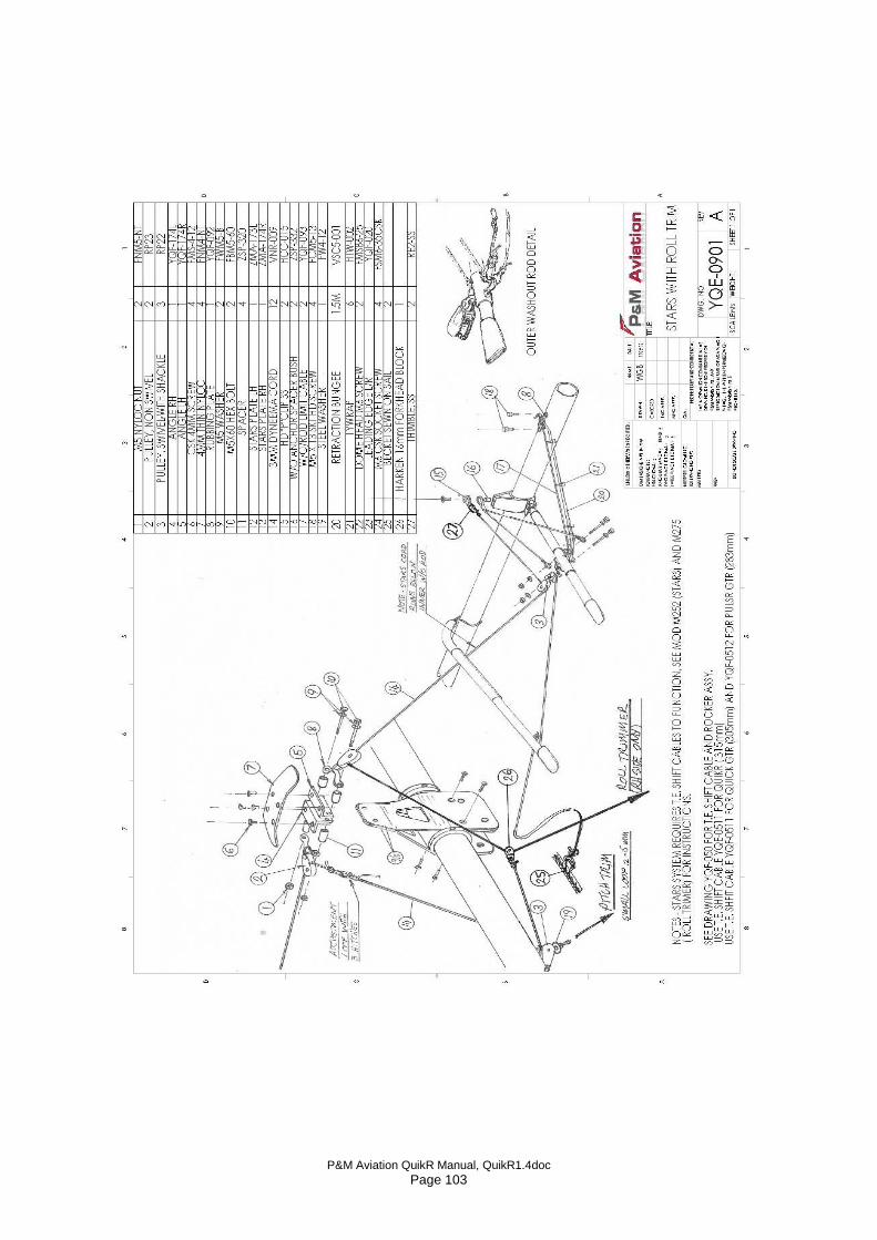
P&M Aviation QuikR Manual, QuikR1.4doc Page 103
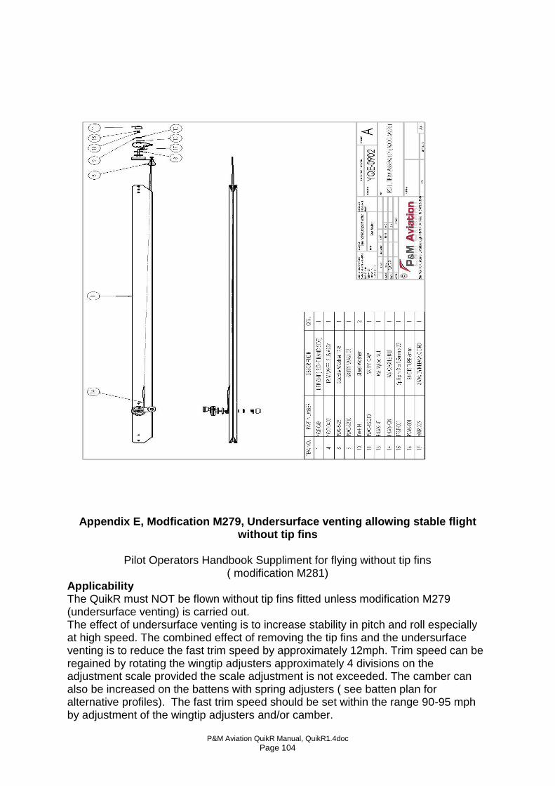
P&M Aviation QuikR Manual, QuikR1.4doc Page 104
Appendix E, Modfication M279, Undersurface venting allowing stable flight
without tip fins
Pilot Operators Handbook Suppliment for flying without tip fins ( modification M281)
Applicability The QuikR must NOT be flown without tip fins fitted unless modification M279 (undersurface venting) is carried out. The effect of undersurface venting is to increase stability in pitch and roll especially at high speed. The combined effect of removing the tip fins and the undersurface venting is to reduce the fast trim speed by approximately 12mph. Trim speed can be regained by rotating the wingtip adjusters approximately 4 divisions on the adjustment scale provided the scale adjustment is not exceeded. The camber can also be increased on the battens with spring adjusters ( see batten plan for alternative profiles). The fast trim speed should be set within the range 90-95 mph by adjustment of the wingtip adjusters and/or camber.