operator’s manual - twinslann0nas/manuals/onan/981-0121...tion and maintenance of the series dkc...
TRANSCRIPT
Operator’s Manual
981-0121 8-89 Prinfad in USA
Safety Precautions Before operatlng the generator set, read the Operator's Manual and become familiar with it and the equipment. Safe and efficient operation can be achieved only if the equip ment Is properly operated and maintained. Many accidents are caused by failure to follow fundamental rules and precau- tions.
The following symbols, found throughout this manual, alert you to potentially dangerous conditions to the operator, service per- sonnel, or the equipment.
. D ' This symbol warns of immediate haz- ards whlch will result In severe personal Injury or death.
1-1 This symbolrefers to a hazard or unsafe practice which can result in severe personal injury or death.
-1 Thls symbolrefers lo a hazard or unsafe practice whlch can result in personal injury or prod- uct or propefty damage.
FUEL AND FUMES ARE FLAMMABLE. Fire and explosion can result from improper practices.
DO NOTfillfuel tankswhile engine is running, unlesstanks are outside the engine compartment. Fuel contact with hot engine or exhaust is a potential fire hazard.
DO NOT permit any flame, cigarette, pilot light, spark, or other ignition source near the generator set or fuel tank.
Fuel lines must be adequately secured and free of leaks. Fuel connection at the engine should be made with an ap- proved flexible line. Do not use copper piping on flexible lines as copper will become brittle if continuously vibrated or repeatedly bent.
Be sure all fuel supplies have a positive shutoff valve.
Do not smoke while servicing lead acid batteries. Lead acid batteries emit a highly explosive hydrogen gas that can be ignited by electrical arcing or by smoking.
EXHAUST GASES ARE DEADLY e Provide an adequate exhaust system to properly expel dis-
charged gases. Visually and audibly inspect the exhaust daily for leaks perthe maintenance schedule. Ensure that exhaust manifolds are secured and not warped. Do not use exhaust gases to heat a compartment. Be sure the unit is well ventilated.
MOVING PARTS CAN CAUSE SEVERE PERSONAL INJURY OR DEATH
Keep your hands, clothing, and jewelry away from moving parts.
Before starting workon the generator set, disconnectstart- ing batteries, negative (-) cable first. This will prevent acci- dental starting.
Make sure that fasteners on the generator set are secure. Tighten supports and clamps, keep guards in position over fans, drive belts, etc.
Do not wear loose clothing or jewelry in the vicinity of mov- ing parts, or while working on electrical equipment. Loose clothing and jewelry can become caught in moving parts. Jewelry can short out electrical contacts and cause shock or burning. If adjustment must be made while the unit is running, use extreme caution around hot manifolds, moving parts, etc.
ELECTRICAL SHOCK CAN CAUSE SEVERE PER- SONAL INJURY OR DEATH
Remove electric power before removing protective shields or touching electrical equipment. Use rubber insulative mats placed on dry wood platforms over floors that are metal or concrete when around electrical equipment. Do not wear damp clothing (particularly wet shoes) or allow skin surface to be damp when handling electrical equip- ment. Use extreme caution when working on electrical compo- nents. High voltages can cause injury or death. DO NOT tamper with interlocks.
Follow all applicable state and local electrical codes. Have all electrical installations performed by a qualified licensed electrician. Tag open switchesto avoid accidental closure.
DO NOT CONNECT GENERATOR SET DIRECTLY TO ANY BUILDING ELECTRICALSYSTEM. Hazardousvolt- ages can flow from the generator set into the utility line. This creates a potential for electrocution or property dam- age. Connectonly throughanapproved isolation switchor an approved paralleling device.
GENERAL SAFETY PRECAUTIONS Coolants under pressure have a higher boiling point than water. DO NOT open a radiator or heat exchanger pres- sure cap while the engine is running. Allow the generator set to cool and bleed the system pressure first.
Benzene and lead, found in some gasoline, have been identified by some state and federal agencies as causing cancer or reproductive toxicity. When checking, draining or adding gasoline, take care not to ingest, breathe the fumes, or contact gasoline. Used engine oils have been identified by some state orfed- era1 agencies as causing cancer or reproductive toxicity. When checking or changing engine oil, take care not to in- gest, breathe the fumes, or contact used oil.
Provide appropriate fire extinguishers and install them in convenient locations. Consult the local fire department for the correct type of extinguisherto use. Do not use foam on electrical fires. Use extinguishers rated ABC by NFPA.
Make sure that rags are not left on or near the engine.
Remove all unnecessary grease and oil from the unit. Ac- cumulated grease and oil can cause overheating and en- gine damage which present a potential fire hazard.
Keep the generator set and the surrounding area clean and free from obstructions. Remove any debris from the set and keep the floor clean and dry.
Do notworkon this equipment when mentally or physically fatigued, or after consuming any alcohol or drug that makes the operation of equipment unsafe.
Ls-9

Table of Contents SECTION TITLE PAGE
SAFETY PRECAUTIONS ........................................ Inside Front Cover TABLE OF CONTENTS .............................................................. 1
About this Manual ............................................................... 1-1 How to Obtain Service .......................................................... 1-1
General ........................................................................... 3-1 Location and Mounting ......................................................... 3-1 Ventilation and Cooling ......................................................... 3-1 Exhaust System .................................................................. 3-3 Fuel Supply System ............................................................. 3-4 Electrical Connections .......................................................... 3-4 Remote Control Connections ................................................... 3-6 Battery Connections ............................................................. 3-6 Preparing Generator Set for Operation ........................................ 3-6 Initial Starting and Checks ...................................................... 3-6
General ........................................................................... 4-1 Pre-Start Checks ................................................................ 4-1 Control Panel .................................................................... 4-1 Starting .......................................................................... -4-2 Stopping ......................................................................... 4-3 Operating Recommendations .................................................. 4-3
Periodic Maintenance Schedule ............................................... 5-1 Generator Set Inspection ....................................................... 5-2 Lubrication System .............................................................. 5-2
Fan Belt .......................................................................... 5-5 Fuel System ...................................................................... 5-6 Air Cleaner ..................................................................... - 5 - 8 Battery ............................................................................ 5-8
Out of Service Protection ..................................................... 5-10
1 INTRODUCTION ................................................................... 1-1
2 SPECIFICATIONS ................................................................. 2-1 3 INSTALLATION .................................................................... 3-1
4 OPERATION ....................................................................... 4-1
Troubleshooting ................................................................. 4-3 5 MAINTENANCE .................................................................... 5-1
...................... Cooling System ........................................... : 5-3
AC Generator ................................................................... -5-9
California Proposition 65 Warning
Diesel engine exhaust and some of its constituents are known to the State of California to cause cancer. birth defects. and other reproductive harm .
i

c
m
Section 1 Introduction ABOUT THIS MANUAL
This manual provides information for installation, opera- tion and maintenance of the Series DKC and DKD generator sets. Study this manual carefully and observe all warnings and cautions. Using the generator set properly and following a regular maintenance schedule will result in longer unit life, better performance, and safer operation.
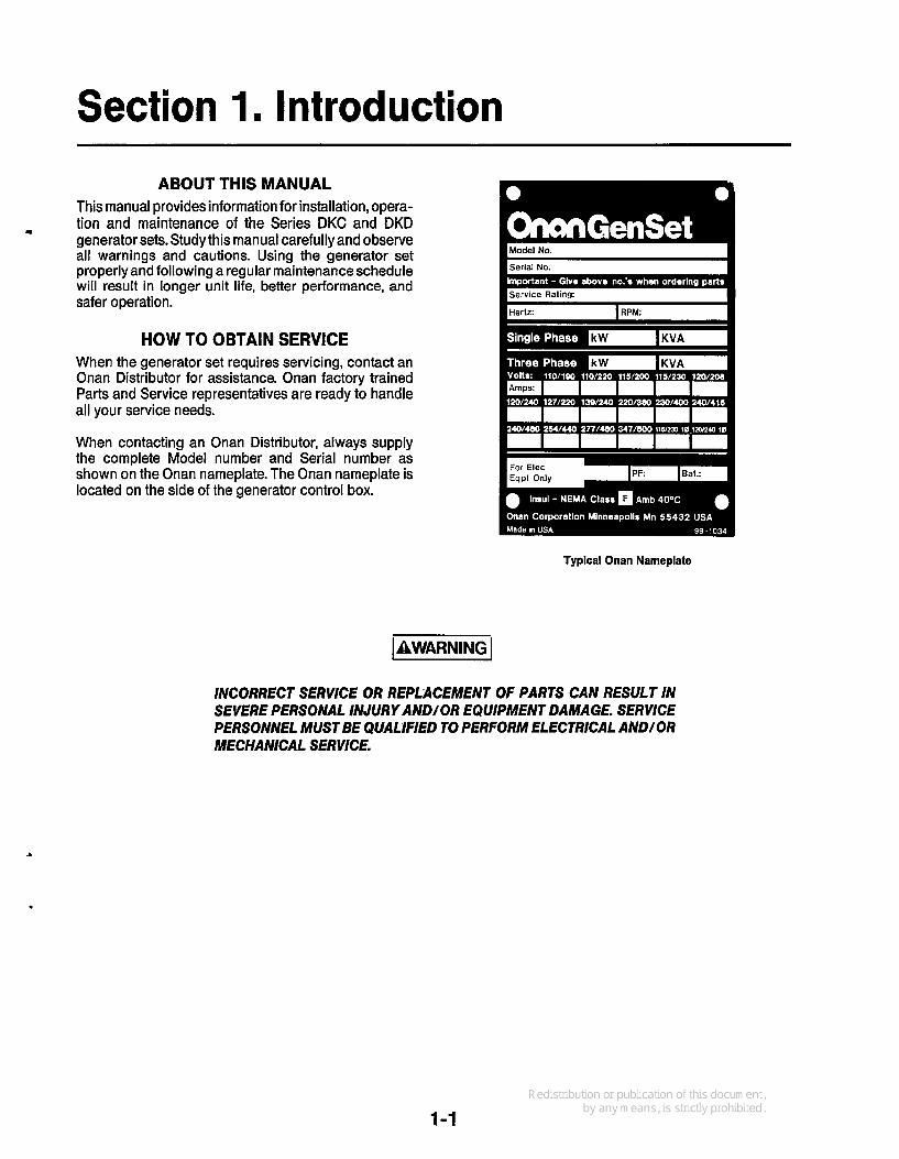
HOW TO OBTAIN SERVICE When the generator set requires servicing, contact an Onan Distributor for assistance. Onan factory trained Parts and Service representatives are ready to handle all your service needs.
Model No. I HService Ratinq:
When contacting an Onan Distributor, always supply the complete Model number and Serial number as shown on the Onan nameplate. The Onan nameplate is located on the side of the generator control box.
Typical Onan Nameplate
INCORRECT SERVICE OR REPLACEMENT OF PARTS CAN RESULT IN SEVERE PERSONAL INJURY AND/OR EQUIPMENT DAMAGE. SERVICE PERSONNEL MUST BE QUALIFIED TO PERFORM ELECTRICAL AND/OR MECHANICAL SERVICE.
1-1

L

Section 2. Specifications
U
GENERATOR Type ......................................................... 4-pole revolving field, brushless, reconnectible
7.5 DKD (3 phase) ......................................................... .7.5 kW (9.735 kVA at 0.8 PF) (1 phase) ............................................................ 7.5 kW (7.5 kVA at 1.0 PF)
4.0 DKC (3 phase) ............................................................ 4.0 kW (5.0 kVA at 0.8 PF) (1 phase) ............................................................ 4.0 kW (4.0 kVA at 1.0 PF)
6.0 DKD (3 phase) ............................................................ 6.0 kW (7.5 kVA at 0.8 PF) (1 phase) ............................................................ 6.0 kW (6.0 kVA at 1.0 PF)
3.5 DKC (3 phase) .......................................................... 3.5 kW (4.375 kVA at 0.8 PF)
60 Hz ....................................................................................... .5 percent 50 Hz ....................................................................................... . 6 percent
Random frequency variation .................................................................... f1 percent
Electronic regulation*. ........................................................................ .3 percent Transformer regulation**. ..................................................................... .5 percent
Electronic regulation*. ........................................................................ f 2 percent Transformer regulation**. .................................................................... f4 percent
Type ................................................. .Vertical, 3 cylinder, 4-stroke Diesel cycle, liquid cooled
DKD ................................. ; .................................................. .57 in.3 (0.93 L) DKC .................................................................................... .41 in.3 (0.68 L)
Engine speed (50/60 Hz) .................................................................. 1 5 0 0 ~ 800 RPM Fuel.. ........................................................................................ .2-D Diesel Fuel inlet .................................................................................. 1 /8 inch NPTF Fuel return.. ............................................................................... .1/8 inch NPTF Maximum fuel pump lift ................................................................ .31 inches (800 mm) Maximum fuel consumption:
7.5 DKD ............................................................................. 0.90 gph (3.75 L/h) 6.0 DKD ............................................................................. 0.75 gph (3.12 L/h) 4.0 DKC ............................................................................. 0.50 gph (1.89 L/h) 3.5 DKC ............................................................................. 0.42 gph (1.57 L/h)
Exhaust outlet. .................................................................... 1-1 /4 inch NPT external Battery requirements:
Voltage ............................................................................................. 12 Cold cranking amps (OOF [-1B0C]) .................................................................... 425
Coolant capacity: DKD ................................................................................. .0.7 gallons (2.6 L) DKC ................................................................................. .1.2 gallons (4.5 L)
Lubricating oil capacity (with oil filter). ................... ,: .................................... 4 quarts (3.8 L) Maximum ambient temperature ............................................................... 122'F (50°C)
Standby ratings: 60 Hertz
50 Hertz
(1 phase) ....................................... .:. .................. 3.5 kW (3.5 kVA at 1.0 PF) Frequency regulation under varying load:
Voltage regulation under varying load:
Random voltage variation:
ENGINE
Displacement:
)I
* - Standard for 3 phase, optional for 1 phase ** - Standard for 1 phase
2-1

L

Y
Section 3. Installation
GENERAL Use these instructions as a general guide. The installa- tion must comply with all local and state building codes, fire ordinances and other applicable regulations. Refer to Onan Technical Bulletin T-030.
LOCATION AND MOUNTING These sets are for installation indoors or within a weather protective housing. Locate the set as close as practical to the load served, considering requirements for mounting, access for service, noise attenuation, exhaust discharge and ventilation.
0 Anchor the base of the set to a substantial and level surface, such as a concrete pad. The outline draw- ing for the set shows the locations for mounting bolts. The set has rubber mounts to isolate vibration.
0 For easier maintenance and service, such as oil changing, it is recommended that the mounting sur- face be 6 to 12 inches (150 to 300 mm) above the floor level.
0 Wood floors should be covered with sheet metal extending at least 12 inches (300 mm) beyond each side and end of the set.
0 Provide at least 2 feet (600 mm) of clearance at each side and end for service and ventilation.
VENTILATION AND COOLING The room or enclosure must beventilated to remove the heat dissipated by the engine, radiator, generator and any other equipment. The engine is liquid cooled, with an integral radiator and fan. The generator has a rotor mounted centrifugal fan for cooling. The ambient temperature must not exceed 122OF (5OOC).
Locate vents so that the incoming air passes over the set, from generator end to radiator end, before being exhausted. Install the outlet vent higher than the inlet vent to promote natural convection.
Install a ventilating fan if natural convection is not adequate.
0 Locate the ventilating openings to take advantage of the prevailing winds.
In regions subject to freezing temperatures provide thermostatically controlled dampersfor the ventilat- ing 'openings.
0 A thermostatically controlled coolant heater is available as an option to keep the engine warm for easier starting in cold weather. It should be con- nected to the normal source of power.
The coolant heater will burn out lEZEEl if it is not submersed in coolant. Fill the engine with coolant before connecting the coolant heater to the source of power.
3-1

RADIATOR AIR CLEANER
OR STARTIRUNISTOP AND
PREHEAT SWITCHES (REMOTE START MODELS)
M-I 532-1
. . FIGURE 3-1. TYPICAL MODEL
,
3-2

EXHAUST SYSTEM Generator sets installed indoors must have the exhaust piped to the out-of-doors, away from doors, windows and vents.
Exhaust gas is deadly. Make sure the exhaust system is adeuuate to
remove all exhaust gas and ihat it does notleak. Fix
Provide a flexible connector to allow the set to rock
0 Provide exhaust piping the same size or larger than the exhaust outlet. See Specifications. Schedule 40 black iron pipe is recommended.
L. exhaust leaks before placing the set in service.
+ on its mounts.
Route the pipe at least 9 in. from combustible con- struction and fuel lines. Use an approved thimble to maintain the clearance through walls (Figure 3-2).
Exhaust piping is hot and can 0 AWARNING cause a fire if clearances are not maintained. Check for compliance with the appli- cable codes.
Provide insulation or guards whereaccidental con- tact with hot exhaust piping is likely.
Providea rain cap if the piping terminatesvertically.
0 Provide a condensate drip leg where piping turns to
0 Slope horizontal pipe to drain to a drip leg or to the
rise vertically (Figure 3-3).
outside.
.
0 Provide sweeping bends to minimize exhaust back pressure.
0 Do not terminate the exhaust pipe near a window, door or building air intake opening. Check for com- pliance with local building codes.
Support exhaust piping with non-combustible hangers.
0 Check the exhaust system back pressure, which must not exceed 27 inches (686 mm) water column.
Listen carefully for exhaust leaks and fix them before placing the set in service.
RAIN CAP
DRIP CAP
INNER SLEEVE
(229 mm)
(229 mm)
(229rnrn\ 1229mm)
IN F EEVE
Diameter of Thimble Must Be 12 Inches (305 mm) . Larger Than Diameter of Exhaust Pipe 13~'
~~
FIGURE 3-2. EXHAUST THIMBLE
IF EXHAUST LINE MUST BE PITCHED UPWARD. CONSTRUCT A TRAP OF PIPE FITTINGS AT I POINT OF RISE
DRAIN CONDENSATION TRAP EXS1M6 I PERIODICALLY ~~
FIGURE 3-3. EXHAUST CONDENSATION TRAP
3-3
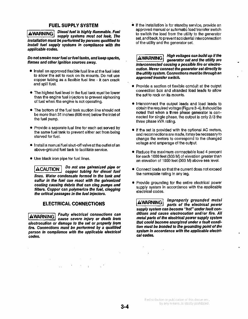
FUEL SUPPLY SYSTEM Diesel fuel is highly flammable. Fuel @@!@I supply systems must not leak. The
installation must be performed by persons qualified to install fuel supply systems in compliance with the applicable codes.
Do not smoke near fuelor fuel tanks, and keep sparks, flames and other ignition sources away.
Install an approved flexible fuel line at the fuel inlet to allow the set to rock on its mounts. Do not use copper tubing as a flexible fuel line - it can crack and spill fuel.
The highest fuel level in the fuel tank must be lower than the engine fuel injectors to prevent siphoning of fuel when the engine is not operating.
The bottom of the fuel tank suction line should not be more than 31 inches (800 mm) below the inlet of the fuel pump.
0 Provide a separate fuel line for each set served by the same fuel tank to prevent either set from being starved for fuel.
0 Install a manual fuel shut-off valveattheoutletof an above-ground fuel tank to facilitate service.
0 Use black iron pipe for fuel lines.
Do not use galvanized pipe or @%%%I copper tubing for diesel fuel lines. Water condensate formed in the tank and sulfur in the fuel can react with the galvanized coating causing debris that can clog pumps and filters. Copper can polymerize the fuel, clogging the critical passages in the fuel injectors.
ELECTRICAL CONNECTIONS
Faulty electrical connections can cause severe injury or death from
electrocution or damage to the set or properfy from fire. Connections must be performed by a qualified person in compliance with the applicable electrical codes.
If the installation is for standby service, provide an approved manual or automatic load transfer switch to switch the load from the utility to the generator set, and back, to prevent accidental interconnection of the utility and the generator set.
High voltages can build up if the generator set and the utility are
interconnected causing a possible fire or electro- cution. Never connect the generator set directly to the utility system. Connections must be through an approved transfer switch.
0 Provide a section of flexible conduit at the output connection box and stranded load leads to allow the set to rock on its mounts.
Interconnect the output leads and load leads to obtain the required voltage (Figure 3-4). It should be noted that when a three phase generator is con- nected for single phase, the output is only 2/3 the three phase kVA rating.
0 If the set is provided with the optional AC meters, and reconnections are made, it may be necessary to change the meters to correspond to the changed voltage and amperage of the output.
0 Reduce the maximum connectable load 4 percent for each 1000 feet (303 M) of elevation greater than an elevation of 1000 feet (303 M) above sea level.
0 Connect loads so that the current does not exceed the nameplate rating in any leg.
Provide grounding for the entire electrical power supply system in accordance. with theapplicable electrical codes.
Improperly grounded metal parts of the electrical power
supply system can become “hot” under fault con- ditions and cause elecirocution and/or fire. All metal parts of the electrical power supply system that could become energized under a fault condi- tion must be bonded to the grounding point of the system in accordance with the applicable electri- cal codes.
1
3-4

Voltage Code J (60 Hz)
120-240 VAC
t, L2 Lo
H 4 H 3
T3TI RECONNECTION DIAGRAM SHOWN FOR
OUTPUT
TRANSFORMER REGULATION Voltage Code P (50 Hz)
110/220v , CL1 115/230V
L1
RECONNECTION T3 T1 T2 T4 DIAGRAM SHOWN FOR
1 15/230 V 50 Hz 120/240 v 60 HZ ; H2
t
1
H1 3 WIRE OUTPUT ?I &I L'o
To Adjust Output Voltage. Move Taps on T21 According to Following Charts.
HOTES: TO ADJUSTOUTPlJTVOLTAGE.MOVE TAPSONTII ACCORDING TO TABLES. I.IN ALL VOLTAGE CONNECTlOhSl50Ah'D60Hz) LEAVE TI ANOT4
2FORM)Hr:USE 52 LEAD(FROM GENION TAPSXI-2 CONNECTED~HI AVO ~4 RESFECTIVELY.
(4TAPS) USE TX LEAD ON TAPS X3-4 3. FOR 5OHz:USESP LEADIFROM GEN) ON TAPS XI-3
'1 6TAPS) USETXLEADONTAPS X4-6 0 . m ~ IIO/EMVANDIIOVCONNECT HZ TO K.
FOR llOV CQNNECTHS T O T 3 1 L I ~ A N D H 3 T O T 2 1 L I ~ . FOR 110/22DV USE H I FOR LIANOH3FORL2(T2ANOT3AREGNB
Electronic Regulation Voltage Codes R, 2, J and P
FIGURE -
3-4.
u L2 H4 H3
120/240 VAC
LO T3
0 D L2 H4 H3
b.FOR IIS/WOVAND 115VlNSJLATE HSAND H6(NOTUSEC) 5. FOR 120/240V ANOIZOVCMIHECT HZTOHS
FOR IZOV COHNECT H6 TO T3 ILI )AND H3 TO T2 (Le). FOR 120/240V USE H 6 FOR LIAH)H3RYIL2IT2ANDTAREGNDL
4. DASHED LINES INDICATE WHEN USER
5. H5 AND H6 LEADS ARE USED ONLY ON SOH1 NOV. IKVPOV AN0 50 Hz 12CV. I201240V CONNECTIONS.
L I
CODE R €4 H Z
230ND01
L3 tz7nzo~ 2 5 1 M I O Y
- CodcsSC 60Hr;Cadc53CS0 Hr-
I I
GENERATOR RECONNE~TION DIAGRAMS 3-5

REMOTE CONTROL CONNECTIONS For remote start models, Onan Model 300-2860-01 TWS (Three-Wire Start) control is available to interface with virtually any transfer switch or remote start/stop signaling device. Connect in accordance with the TWS Installation Manual.
2
4 n (1.24 m)
BATTERY CONNECTIONS See Specifications for minimum battery requirements. Locate the battery as close to the starter motor as prac- tical. Connect the positive (+) post to thestartersolenoid terminal. Connect the negative(-) postto a solid ground connection on the engine. Be sure all battery cable connections are tight (Figure 3-5).
~
1 0 00 000 0000
5n 7 n 9 n 11 n i 4 n (1.55 m) (2.17 m) (2.79 m) (3.41 m) (4.34 m)
Reversed battery connections can damage the charging circuit.
Batteries emit highly explosive hyd- rogen gas. Never smoke near a bat-
tery, and keep sparks, flames and other sources of ignition a way. Always disconnect tbe negative (-) cable first, and reconnect it last, to prevent sparks if a tool accidentally touches the frame of the set or otber grounded metal parts while connecting or disdonnect- ing the positive (+) cable.
PREPARING GENERATOR SET FOR OPERATION
Inspect the engine visually. Check for loose or missing parts and any damage that may have occurred in shipment.
Oil, fuel, and coolant have been (ACAUTIONI drained from the engine prior to shipping from factory. Operation without oilor coolant will damage engine.
Before attempting the initial start of the generator set, be sure it is serviced for operation. Refer to the Mainte- nance section of this manual for the proper procedures.
INITIAL STARTING AND CHECKS Before trying to start set, prime the fuel system (see Maintenance section).
BATTERY POSITIVE STARTING MOTOR SOLENOID CONNECTION
CONNECT NEGATIVE BATTERY TERMINALTO GROUND STUD ES-1446-1
CABLE SIZE
FIGURE 3-5. BATTERY CONNECTIONS
1. Start the generator set by holding the switch on engine contol panel in the Preheat position for 15- 30 seconds. Then turn or press the switch to Start position. The engine should start within a few seconds. Release switch immediately after engine start
2. Monitor the engine control panel and note the oil pressure, coolant temperature, and battery charge voltage (if equipped). Referto the Operationsection of this manual for normal readings. At operating temperature, all readings should slay within the normal range.
3-6

3. Check the exhaust system for leaks, visually and audibly. Note the security of the exhaust system supports. If any leaks are found, shut down the generator. set immediately and repair.
Exhaust gas is deadly! Shut down the generator set imme-
diately if you discover an exhaust leak or exhaust component needing replacement. Do not use the generator set until you have the exhaust system repaired.
4. Checkthegeneratorsetforfuel, oil orcoolant leaks. If any are found, shut down the generator set and repair leak before making any more checks.
5. Check generator output voltage and frequency. Connect an accurate AC voltmeter and frequency meter across two line terminals.
).
h
High voltage is dead/y. Use tools and test probes with
insulated handles, remove jewelry and make sure your hands, clothes and shoes are dry. Secure the control box cover as soon as adjustments have been made.
A. Output frequency is determined by engine speed and normally does not require adjust- ment. Call an authorized Onan Service Center for assistance if needed.
B. If the set has an electronic voltage regulator, adjust the voltage adjust potentiometer (Figure 3-6) while the set is running without any load connected.
Do not adjust the Volts/Hz. -1 Adjust potentiometer as i t may be impossible to reset for proper opera- tion. It is factory set using special calibration equipment.
C. If the voltage is transformer regulated, it is adjusted by moving the taps on the transformer (T21), in accordance with Figure 3-4. Stop the set before reconnecting the taps. Recheck the voltage.
I ADJUST ' HERE
- I
II I Ill
111 DO NOT
JADJUST VOLTAGE ADJUST
VOLTSlHZ ADJUST
I ~~~~~~ ~ ~
FIGURE 3-6. ELECTRONIC REGULATOR BOARD
3-7


.
Section 4. Operation ~AWARNING I
EXHAUST GAS IS DEADLY!
Exhaust gases contain carbon monoxide, an odorless and colorless gas. Carbon monoxide is poisonous and can cause unconsciousness and death. Symptoms of carbon monoxide poisoning can include:
Dizziness Nausea 0 Muscular Twitching Headache 0 Vomiting
0 Weakness and Sleepiness
0 Throbbing in Temples
lnability to Think Coherently
IF YOU OR ANYONE ELSE EXPERIENCE ANY OF THESE SYMPTOMS, GET OUT INTO THE FRESH AIR IMMEDIATELY. If symptoms persist, seek medical aften- tion. Shut down the unit and do not operate until it has been inspected and repaired.
Protection against carbon monoxide inhalation includes proper installation and regular, frequent visual and audible inspections of the complete exhaust system.
1-PIEM
GENERAL This section covers starting and operating the generator set. Read through this entire section before attempting to start the set. Observe all of the precautions.
PRE-START CHECKS Before starting, be sure the following checks have been made and the unit is ready for operation. Refer to the Maintenance section for the proper procedures.
Lubrication Check the engine oil level. Keep the oil as near as possible to the full mark.
Coolant The coolant level should come near the top of the radia- tor. Do not check while the coolant is hot.
Remove the radiator pressure cap slowly after the engine has cooled.
The sudden release of pressure from a heated cooling system can result in loss of coolant and possible per- sona/ injury from the hot coolant.
4
CONTROL PANEL The following describes the function and operation of the generator set controls. All instruments and control switches are located on the face of the control panel as illustrated in Figure 4-1.
GaugeslMeters and Switches Running Time Meter: Registers the total number of hours that the unit has run. Use it to keep a record for periodic servicing. Time is cumulative; meter cannot be reset.
DC Voltmeter (Optional): Monitors B+ voltage useful to determine battery condition and charge system opera- tion. See Battery portion of Maintenance section.
Coolant Temperature Gauge (Optional): Shows engine coolant temperature. The gauge is wired to a sensor on the engine and has a range of 100" to 25OOF (40" to
Optional Pressure Gauge (Optional): Shows engine lubricating oil pressure. The gauge has a range of 0 to 100 psi (0 to 700 kPa) and is connected to an engine sensor.
121 "C).
Fuel
primed for operation (see Maintenance section). Preheat-Stop Start Switch (Electric Start at Set
generator set locally. Make sure the tanks are full and the fuel system Models); This is a key switch that starts and stops the
Stop-Run-Start and Preheat Switches (Remote Start Models):Switches (two) for operating the set locally as well as by remote control.
4-1

Circuit Breakers Fault Reset:A manual reset breaker that shutsdown the engine for low oil pressure, high coolant temperature, and overspeed.
DC Control Breaker: A 15 ampere breaker providing protection to the control box wiring from short circuits or overload.
AMBIENT TEMPERATURE
Above 86°F (30°C) Between 50' to 86" F (IO" to 30°C) Between 32' to 50°F (0" to 10°C) ktween 0" to 32'F (-18" to 0%) Below 0°F (-18°C)
Line Circuit Breakers: Protects generator from a short circuit or other overload. When furnished by Onan they are mounted on the control box. Replacement must meet specs for proper protection.
Field Breaker (Electronic Regulators 0nly):A 3 ampere breaker providing generator field protection from cef- tain voltage regulator failures.
~
PREHWTING TIME
About 10 sec. About 15 sec. About 20 sec. About 30 sec. About 45 sec.
Fuse: Located at the starter solenoid and protects the control from shorts or overload. An open fuse will dis- able the control. It is rated at 30 amperes.
LINE CIRCUIT BREAKER
STARTING Thissection covers starting and stopping of thegenera- tor set and how to perform start-up checks.
-
Starting Procedure
1. Turn the keyswitch to the Preheat position and hold for 10 to 45 seconds depending upon temperature as shown below.
2. Turn key switch to Start position. Release the key to run position immediately when engine starts.
3. If engine does not start after cranking 30 seconds, release Start switch. Wait two minutes and then repeat Step 1.
-1 Excessive cranking can over- heat and damage fhe starter. Do
not engage starter for periods longer than 30 seconds. Allow two minutes for starter to cool between cranks.
4. If enginedoes not start on second try, checkthe fuel supply and be sure system has been primed. See Fuel System in the Maintenance section.
B
Start-up Checks Check.any optional gauges on control box after the engine is started. Observe the oil pressure gauge immediately.
Oil Pressure Gauge: The oil pressure should be in the range Of 40 to 60 psi (276 to 414 kPa) when the engine is at operating temperature.
DC Voltmeter: Normal B+ voltage during operation should be 14 to 15 volts.
Water Temperature Gauge: The water temperature should be in the range of 165" to 195°F (74" to 91 "C) depending on the load and ambient temperature.
FIGURE 4-1. CONTROL BOX FRONT PANEL
4-2

STOP PING I I Before Stopping Run the generator set at no load for three to five minutes before stopping. This allows the lubricating oil and engine coolant to carry heat away from the combustion chamber and bearings.
Failure to allow running time for k@@@!l engine cooling withouf load can result in engine damage. Make sure generator set runs unloaded for at /east three minutes.
To Stop: Turn or push the switch to the Stop position, and hold it there until the engine slows enough not to start again.
t
OPERATING RECOMMENDATIONS Break-In Drain and replace the crankcase oil after the first 35 hours of operation on new generator sets. Refer to the Maintenance section of this manual.
No-Load Operation Hold periods of no-load operation to a minimum and avoid if possible. No-load operation allows combustion chamber temperatures to drop so low that the fuel does not burn completely. This results in carbon deposits which can clog injectors, cause piston rings and valves to stick and can cause cylinder glazing. If it is necessary to run the engine for long periods at no load, connect a “dummy” electrical load to the generator.
Exercise Period To avoid excessive engine wear, exercise the generator set at least once a week for a minimum of 30 minutes. Run the set with a load applied to allow the engine to reach normal operating temperature. Exercising will keep the engine parts lubricated, maintain fuel prime, and prevent electrical relay contacts from oxidizing. Top off the fuel tank after each exercise period.
TROUBLESHOOTING DC Control The DC control has a number of sensors that continu- ously monitor the engine for abnormal conditions such as low oil pressure, high coolant temperature and over- speed (optional). If any one of these conditions occur, the control stops the engine. See Figure 4-2.
The following sections describe the operation of the fault systems and suggested items the operator can check. If a major problem is indicated, contact an Onan Dealer or Distributor for help or service.
1
HIGH COOLANT TEMP. SWITCH
SPEED TCH
BREAKER SWITCH ES-1U9-2 I
FIGURE 4-2. FAULT SENSOR LOCATION
4-3

Fault Reset Breaker: The control panel Fault Reset breaker will trip for any one of the fault conditions des- cribed separately below. The white breaker reset button pops out about 1 /4 inch (6 mm) when a fault occurs. Locate the problem and make the necessary correc- tions before resetting breaker and starting the generator set. All fault shutdowns except overspeed are delayed 5 seconds to avoid nuisance tripping.
Low OilPressure: Remove dipstick and check oil level. If low, add oil to bring level up to full mark. Inspect engine exterior for leaks and repair as necessary. The oil pressure switch actuates the fault circuit if pressure drops below 9 psi (62 kPa).
High Coolant Temperature: If fault occurred during operation, observe Coolant Temperature Gauge (option) for indication of temperature over 25OOF (121 OC). The coolant thermostat switch closes at this temperature and actuates the fault circuit.
FIELD BREAKER (ELECTRONIC REGULATORS ONLY)
I LINE CIRCUIT BREAKERS
I ES-1448
Check coolant level in radiator after allowing engine to cool down. Ensure pump belt is OK and has proper tension. Also check cooling system cleanliness (free- dom from contaminants, rust, sludge build-up, etc.).
Overspeed 0pfion:This optional sensor is mounted on the front of the engine crankshaft. It is factory adjusted to shut down 60 hertz units at 2200 r/min f90 r/min, 50 hertz units at 1900 r/min f90 r/min.
AC Control The AC control may use two circuit breakers on the control box depending upon ordered options. See Fig- ure 4-3. If either one trips, it results in loss of generator AC power output. They function as follows:
Field Breaker (Electronic Regulators 0nly):A 3 ampere breaker providing generator field protection from cer- tain voltage regulator failures. If resetting the breaker returns power only momentarily, then trips again, con- sult an Onan dealer or distributor for service.
Line Circuit Breakers: When supplied by Onan, these breakers are mounted on the side of the control box. They protect the generator from a short circuit or other overload.
FIGURE 4-3. AC CONTROL BREAKERS
4-4
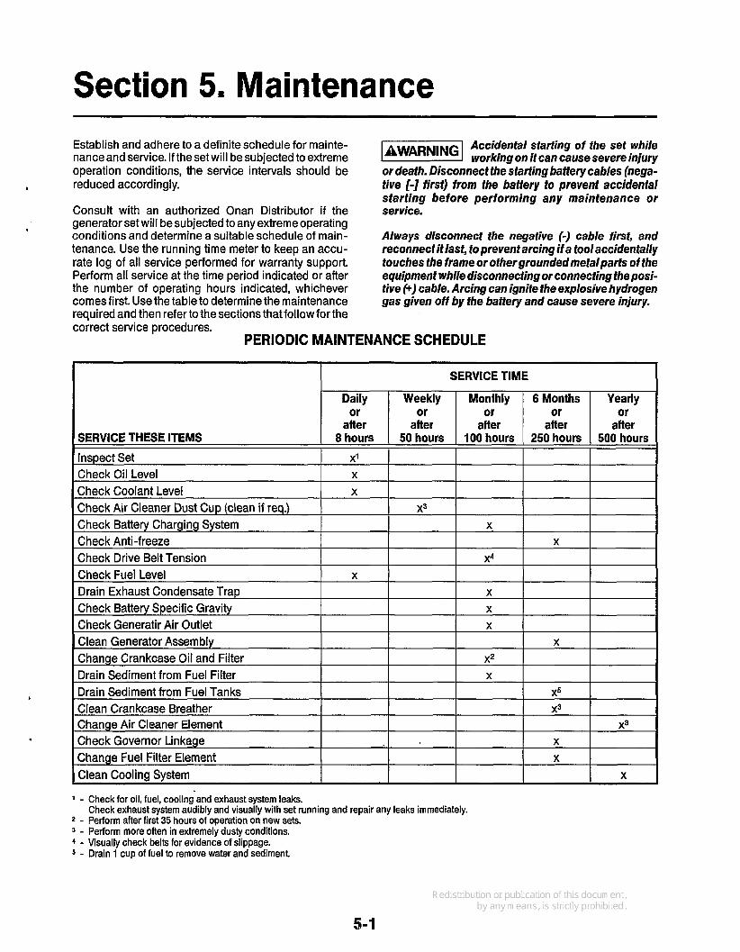
Section 5. Maintenance Establish and adhere to a definite schedule for mainte- nance and service. If the set will be subjected to extreme operation conditions, the service intervals should be
Consult with an authorized Onan Distributor if the generator set will be subjected to any extreme operating conditions and determine a suitable schedule of main- tenance. Use the running time meter to keep an accu- rate log of all service performed for warranty support. Perform all service at the time period indicated or after the number of operating hours indicated, whichever comes first. Use the table to determine the maintenance reauired and then refer tothe sections that follow for the
4 reduced accordingly.
*
1-1 Accidental starting of fhe set while working on it can cause severe injury
or death. Disconnect the starting battery cables (nega- tive [-I first) from the battery to prevent accidental starting before performing any maintenance or service.
Always disconnect the negative (-) cable first, and reconnect it last, to prevent arcing if a tool accidentally touches the frame or othergroundedmetalparts of the equipment while disconnecting or connecting the posi- tive (+) cable. Arcing can ignite the explosive hydrogen gas given off by the battery and cause severe injury.
cokect service procedures. PERIODIC MAINTENANCE SCHEDULE
.
I I SERVICE TIME
Daily Weekly Monthly or or or
afler afler after SERVICE THESE ITEMS 8 hours 50 hours 100 hours
1 - Check for oil, fuel, cooling and exhaust system leaks.
2 - Perform after first 35 hours of operation on new sets. 3 - Perform more often in extremely dusty conditions. 4 - Visually check belts for evidence of slippage. 5 - Drain 1 cup of fuel to remove water and sediment
Check exhaust system audibly and visually with set running and repair any leaks immediately.
I
x3 I I x3
5-1

GENERATOR SET INSPECTION
I
During operation, be alert for mechanical problems that could create unsafe or hazardous conditions. The fol- lowing sections cover several areas that should be fre- quently inspected to provide continued safe operation.
Engine Gauges Check the following while the generator set is operating.
OilPressure Gauge (0ptional):The oil pressure should be in the range of 40 to 60 psi (276-414 kPa) when the engine is at operating temperature.
Coolant Temperature Gauge (Optional): The water temperature should be in the range of 165' to 195'F (74' to 91OC) depending on the load and ambient temperature.
I
DC Voltmeter (Optional): Normal B+ voltage during operating should be 14 to 15 volts.
Exhaust System With the generator set operating, inspect the entire exhaust system including the exhaust manifold, exhaust elbow, muffler and exhaust pipe. Visually and audibly check for leaks at all connections, welds, gaskets, and joints. If any leaks are detected, have them corrected immediately.
Inhalation of exhaust gases can l3iMMGl result in serious personal injury or death. Inspect exhaust system audibly and visually for leaks daily. Shut down the set and.repair leaks immediately.
Fuel System With the generator set operating, inspect the fuel supply lines, return lines, filters, and fittings for leaks. Check any flexible sections for cuts, cracks and abrasions and make sure they are not rubbing against anything that could cause breakage.
-1 Leaking fuel will create a fire hazard which can result in severe per-
sonal injury or death if ignited by a spark. If any leaks are detected, shut down the set and repair leaks immediately.
DC Electrical System With the generator set off, check the terminals on the battery for clean and tight connections. Loose or cor- roded connections create resistance which can hinder starting. Clean and reconnectthe battery cables if loose. Always connect the negative battery cable last to reduce the possibility of arcing.
Ignition of explosive battery gases can cause severepers~nalinjury. Do
not smoke while servicing batteries.
Mechanical With the generator set stopped, check for loose belts, and fittings, leaking gaskets and hoses, or any signs of mechanical damage. If any problems are found, have them corrected immediately. With theset running, listen for any unusual noises that may indicate mechanical problems and check the oil pressurefrequently. Investi- gate anything that indicates possible mechanical problems.
LUBRICATION SYSTEM The engine oil was drained from the crankcase prior to shipment. Before the initial start, the lubrication system must be filled with oil of the recommended classification and viscosity. Refer to the Specificafionssection for the lubricating oil capacity.
Oil Recommendations Use oils with the American Petroleum Institute (API) classification SF/CD in viscosities per temperature as shown in the chart below.
C-30 -20 -10 0 10 20 30 40 50 TEMPERATURE RANGE YOU EXPECT BEFORE NEXT OIL CHANGE
Lslln-1
When selecting the oil viscosity, pick the viscosity that is right for the lowest temperature expected. Oil that is too thick may result in a lack of lubrication when the engine is started. Use a lower viscosity oil as the ambient temperature reaches the lower end of the scale.
Do not use synthetic oil, non-detergent oil, and do not mix different brands of oil.
I
Engine Oil Level Check the engine oil level during engine shutdown periods at the intervals specified in the Maintenance Table. The oil dipstick and oil fill are located on the side of the engine (see Figure 5-1). The dipstick is stamped with FULL and ADD to indicate the level of oil in the crankcase. For accurate readings, shut off the engine and wait approximately 10 minutes before checking the oil level. This allows oil in the upper portion of the engine to drain back into the crankcase.
5-2

Keep the oil level as near as possible to the FULL mark on the dipstick. Remove the oil fill cap and add oil of the same quality and brand when necessary.
Do not operate the engine with the oil level below the ADD mark or above
the FULL mark. Overfilling can cause foaming or aera- fion of the oil while operation below the ADD mark can cause loss of oil pressure.
Oil and Filter Change Change the oil and filter at the intervals recommended in the maintenance table. Use oil that meets the API classification and viscosity requirements as indicated in the previous section.
I
v
Engine Oil Change: Run engine until thoroughly warm before draining oil. Stop the engine, place a pan under the drain outlet and open the drain valve. After the oil is completely drained, close the drain valve. Refill with oil of the correct API classification and appropriate SAE viscosity grade for the temperature conditions.
Hot crankcase oil can cause burns if it is spilled or splashedon skin. Keep
fingers and hands clear when removing fhe oil drain plug and wear protective clothing.
Oil Filter Change: Spin off oil filter and discard it. Tho- roughly clean filter mounting surface. Apply a thin film of oil to filter gasket and install new element. Spin element on by hand until gasket just touches mounting pad and then an additional 1 /2 turn. Do not overtighten.
With oil in crankcase, start engine and check for leaks around filter element. Retighten onlyas much as neces- sary to eliminate leaks, but do not overtighten.
COOLING SYSTEM The cooling system on each set is drained prior to shipping and must be refilled before being operated. The cooling system capacity of the standard unit with set mounted radiator is shown in the Specifications section.
Coolant Requirements A satisfactory engine coolant inhibits corrosion and pro- tects against freezing. A solution of ethylene glycol anti- freeze (permanent type) and water is recommended for normal operation and storage periods. Choose only a reliable brand of anti-freeze that contains a rust and corrosion inhibitor but does not contain a stop-leak additive.
4
M-1532-1
FIGURE 5-1. ENGINE OIL
5-3

The water used for engine coolant should be clean, low in mineral content, and free of any corrosive chemicals such as chloride, sulphate, or acid. Use soft water whe- never available. Well water often contains lime and other minerals which eventually may clog the radiator core and reduce the cooling efficiency.
Do not exceed a 50150 mixture of ethylene glycol and water. A stronger mixture will alter heat transfer proper- ties of the coolant.
Filling the Cooling System Verify that all drain cocks are closed and all hose clamps secure. Remove the cooling system pressure cap and slowly fill the cooling system with the recom- mended coolant.
When the engine is first started, remove the pressure cap and monitor the coolant level. As trapped air is expelled from thesystem, the coolant level will drop and additional coolant should be added. Replace the pres- sure cap when the coolant level is stable.
Coolant Level Check the coolant level during shutdown periods at the intervals specified in the Maintenance Table. Remove the radiator cap after allowing the engine to cool and if necessary, add coolant until the level is near the top of the radiator. See Figure 5-2.
Coolant in a warm engine is under @!@!&I pressure and can flash to steam causing severe burns if the radiator cap or drain cock are opened. Let the engine cool down before opening the radiator cap or drain cock.
High Engine Temperature Cutoff will -1 shut down engine in an overheat condition only if coolant level is sufficiently high to physically contact shutdown switch. Loss of coolant will allow engine to overheat without protection of shutdown device, thereby causing severe damage to the engine. The engine coolant level must be main- tained to ensure operationalintegrity of cooling system and engine coolant overheat shutdown protection.
Flushing and Cleaning For efficient operation, the cooling system should be drained, flushed, and refilled once a year.
To drain the system completely, the radiator drain and the cylinder block drain located on the left side of engine must be opened. See Figure 5-2.
RADIATOR CAP,
M-I53
DRAIN COCK
M-1532-1
FIGURE 5-2. COOLING SYSTEM COMPONENTS
5-4
Chemical Cleaning:Thoroughly clean the cooling sys- tem if rust and scale have collected on the engine water jacket or in the radiator. Rust and scale slow down heat absorption and can block the coolant flow. Use a good radiator cleaning compound in accordance with instructions furnished by the supplier.
Flushing:After cleaning or before filling thesystem with new coolant, drain the block and radiator and fill with
drain the system completely. Refill with the recom- mended coolant.
Never pour hot water into a cold k@!!%!l engine or cold water info a hot engine. Doing so can crack the head or the cylinder block. Do not operate the unit without water for even a le w minutes.
1 clean water. Operate the set for 10 minutes and then
1
Thermostat Replace thermostat when it is broken, corroded, or sticks in the open or closed position. If engine overheats or does not reach and maintain a minimum operating temperature, the thermostat should be replaced.
The thermostat can be removed for replacement using the following procedure:
1. Let the engine cool and then drain the cooling
2. Remove capscrews and washers that secure ther-
3. Raise thermostat cover with radiator hose intact and
4. Remove thermostat cover gasket and thermostat 5. Clean, inspect, and remove any gasket material
system.
mostat cover to water pump housing.
position it to one side.
from the thermostat cover and housing.
Use a new gasket when replacing thermostat. Refill cooling system with the recommended antifreeze coolant.
Pressure Cap Closed cooling systems make use of a pressurized cap to increase the boiling point of the coolant and allow higher operating temperatures. Pressure caps should
malfunction. 4 be replaced every two years or sooner if they
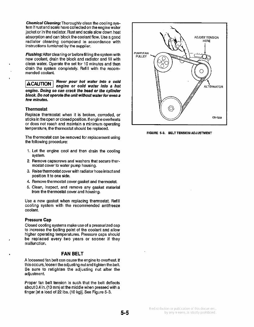
* FAN BELT A loosened fan belt can cause the engine to overheat. If thisoccurs, loosen the adjusting nutand tighten the belt. Be sure to retighten the adjusting nut after the adjustment.
Proper fan belt tension is such that the belt deflects about 0.4 in. (10 mm) at the middle when pressed with a finger [at a load of 22 Ibs. (10 kg)]. See Figure 5-3.
PUMP/FAN PULLEY
FIGURE 5-3. BELT TENSION ADJUSTMENT
5-5

The belt can be removed for inspection or replacement by loosening the adjustment nut and pushing alternator inward. Inspect fan belt for excessive slickness, oil soak, wear, tear, cracks and overstretching. Replace if needed.
FUEL SYSTEM Use only a good quality fuel obtained from a reputatable supplier. The quality of fuel used is important in obtain- ing dependable performance and satisfactory engine life, Fuels must be clean, completely distilled, well refined, and non-corrosive to fuel system parts.
Diesel fuel is highly flammable. Do not smoke near fuel, and keep
sparks, flames and other sources of ignition away.
Fuel Recommendations Use ASTM 2-D (No. 2 Diesel) or ASTM 1 -D (No. 1 Diesel) fuel with a minimum Cetane number of 45. Number 2 diesel fuel gives the best economy and performance under most operating conditions, Use number 1 diesel fuel when ambient temperatures are below 0°C (32') and during 1ong.periods of light engine load.
Use low sulfur content fuel having a cloud point of at least 10 degrees below the lowest expected fuel temperature. Cloud points is the temperature at which wax crystals begin to form in diesel fuel.
Fuel Handling Precautions Take appropriate precautions to prevent the entrance of dirt, water or contaminants into the fuel system. Filter or strain the fuel as the tank is filled.
Due fo fhe precise tolerances of die- m selinjecfion sysfems, dirt or wafer in fhe iuelcan cause severe damage to both fhe injection pump and injector nozzles. Take special precautions to keep the fuel clean and free of water.
To avoid condensation problems, keep fuel supply tanks as full as possible by filling up each time the engine is used. In cold weather, warm fuel returning from the injectors heats the fuel in the supply tank. If the fuel level is low, the upper portion of the tank tends to form condensation. In warm weather, both the fuel and the tank will be warm during the daytime. At night, cool air tends to lower the temperature of the tank more rapidly than the temperature of the fuel. If the fuel level is low, the upper portion of the tank will cool more rapidly and tend to form condensation.
Condensation (wafer) can cause clogging of fuel filters as well as freezing problems. In addition, water mixing with the sulphur in the fuel forms acid which can cor- rode and damage engine parts.
Priming the Fuel System The fuel system mustbe primed priorto initial start up or after enginshas run out of fuel.
,
.
5-6

Low Pressure Fuel System: The transfer pump, fuel filter and injection pump housing comprise the low pressure fuel system. Use the following procedure to remove the trapped air from the system.
1. Fill fuel tank and open shut off valve. 2. Remove filter element and bowl assembly. Fill with
fuel and replace. 3. Loosen the air bleed screw at fuel filter. See Figure
5-4. 4. Actuate the priming level (Figure 5-5) on the side of
the transfer pump. When fuel flows free of air bub- bles, close bleed screw. Collect waste fuel in a container and wipe assembly dry.
5. Loosen air bleed screw on injection pump and actuate priming lever on the transfer pump (Figure 5-4).
6. Tighten bleed screw when fuel flows free of air bubbles.
High Pressure Fuel System: The injection pump, fuel injection lines and fuel injectors comprise the high pressure fuel system. This part of the system is usually self-priming since any trapped air is usually forced out through the injection nozzles.
Fuel Filter The filter replacement interval will vary according to the fuel quality and cleanliness. Using the wrong fuel or dirty fuel will shorten the service life of the filter.
Refer to the Periodic Maintenance Schedule for the recommended filter change interval. However, if the engine shows signsof fuel starvation (reduced power or surging), change the fuel filter. Be sure to lubricate the O-ring on the new filter with clean diesel fuel. Turn the filter by hand one half turn past the point where the O-ring just touches the filter bracket flange. Prime the system.
FUEL PUMP
INJECTOR AIR
BLEED SCREW
1 \ FUEL
RETURN "7
AIR BLEED / SCREW FUEL
FILTER
M-1532-1
FIGURE 5-4. INJECTION PUMP FUEL SYSTEM
PRIMING LEVER I TRANSFER
FS-1533-1
FIGURE 5-5. FUEL TRANSFER PUMP
5-7
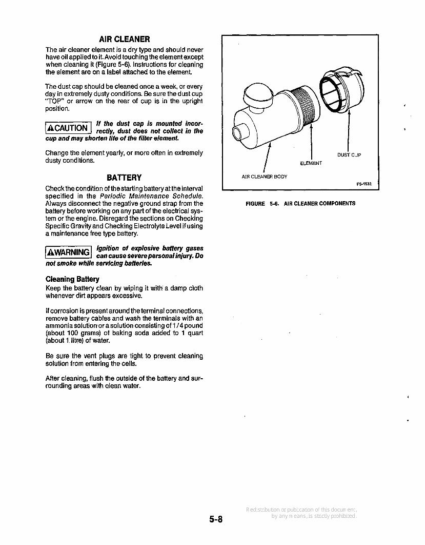
AIR CLEANER The air cleaner element is a dry type and should never have oil applied to it. Avoid touching the element except when cleaning it (Figure 5-6). Instructions for cleaning the element are on a label attached to the element.
The dust cap should be cleaned once a week, or every day in extremely dusty conditions. Be sure the dust cup “TOP” or arrow on the rear of cup is in the upright position.
If the dust cap is mounted incor- 1-1 rectly, dusf does not collect in the cup and may shorten life of the filter element.
Change the element yearly, or more often in extremely dusty conditions.
BATTERY Check the condition of the starting battery at the interval specified in the Periodic Maintenance Schedule. Always disconnect the negative ground strap from the battery before working on any part of the electrical sys- tem or the engine. Disregard the sections on Checking Specific Gravity and Checking Electrolyte Level if using a maintenance free type battery.
Ignition of explosive battery gases 1-1 can cause severe personalinjury. Do not smoke while servicing batteries.
Cleaning Battery Keep the battery clean by wiping it with a damp cloth whenever dirt appears excessive.
If corrosion is present around the terminal connections, remove battery cables and wash the terminals with an ammonia solutionor a solution consisting of 114 pound (about 100 grams) of baking soda added to 1 quart (about 1 litre) of water.
Be sure the vent plugs are tight to prevent cleaning solution from entering the cells.
DUST CUP I ELEMENT I
I AIR CLEANER BODY I FS-1532 ~
FIGURE 5-6. AIR CLEANER COMPONENTS
After cleaning, flush the outside of the battery and sur- rounding areas with clean water.
5-8

Keep the battery terminals clean and tight. After making connections, coat the terminals with a light application of petroleum jelly or non-conductive grease to retard corrosion.
Checking Specific Gravity Usea battery hydrometerto checkthespecific gravityof the electrolyte in each battery cell.
Baffery electrolyte can cause severe eye damage and burns to the skin.
Wear goggles, ruibber gloves and a protective apron when working with batteries.
Hold the hydrometer vertical and take the reading. Cor- rect the reading by adding four gravity points (0.004) for every five degrees the electrolyte temperature is above 80°F (27°C) or subtracting four gravity points for every five degrees below 80°F (27°C). A fully charged battery will have a corrected specific gravity of 1.260. Charge the battery if the reading is below 1.215.
Checking Electrolyte Level Check the level of the electrolyte (acid and water solu- tion) in the batteries at least every 100 hours of operation.
Fill the battery cells to the bottom of the filler neck. If cells are low on water, add distilled water and recharge. If one cell is low, check case for leaks or for a bad cell. Keep the battery case clean and dry. An accumulation of moisture will lead toa more rapid discharge and battery failure.
Do not add wafer in freezing weafher laCAUTlONI unless the engine wi// run long enough (two to fhree hours) to assure a fhorough mix- ing of water and electrolyte.
AC GENERATOR There are no brushes, brush springs or collector rings requiring service on these generators. Periodic inspec- tions, coinciding with engine oil changes should be performed.
Remove the generator end bell cover and inspect the rotating rectifier assembly to make sure the diodes (see Figure 5-7) are free of dust, dirt and grease. Excessive foreign matter on these diodes and heat sinks will cause the diodes to overheat and will result in their failure. Blow out the assembly periodically with filtered low pressure air.
Excessive foreign matter on diodes and heat sinks wi// cause overheat-
ing and possible failure.
n ROTATING
FIGURE 5-7. GENERATOR END VIEW
5-9

Generator Bearing Inspect the bearing for evidence of outer case rotation every 1000 hours of running.
Replace the bearings every five years. Deteriotation of the bearing grease due to oxidation makes this replacement necessary.
If generator requires major repair or servicing, contact an authorized Onan dealer or distributor.
OUT-OF-SERVICE PROTECTION The inherent lubricating qualities of No. 2 diesel fuel should protect the cylinders of a diesel engine for at least 30 days when the unit is not in service. To protect an engine that will be out of service for more than 30 days, proceed as follows:
1. Exercise the generator set as described in the OPERATION section until the engine is up to operat- ing temperature.
2. Shut down engine and disconnect the battery. Store battery in a cool dry place and connect to a charger every 30 days to maintain full charge.
7 1 Baffery electrolyte can cause severe eye damage and burns to
the skin. Wear goggtes, rubber gloves and a pro- tective apron when working with batteries.
3. Drain the oil base while still warm. Replaceoil filter. Refill crankcase and attach a tag indicating viscos- ity of oil used.
4. Check the coolant level andadd morecoolant if the level is low. If freezing temperatures are possible, test strength of coolant mixture.
5. Plug exhaust outlets to prevent entrance of mois- ture, bugs, dirt, etc.
6. Cleanand wipe entire unit. Coat partssusceptibleto rust with a light coat of grease or oil.
Returning a Unit to Service Refer to preceding paragraphs in this Maintenancesec- tion for specific service procedures.
1. Remove plug from exhaust outlet. 2. Check tag on oil base and verify that oil viscosity is
still correct for existing ambient temperature. 3. Clean and check battery. Measure specific gravity
(1.260 at 80°F [27OC] and verify level to be at split ring. If specific gravity is low, charge until correct value is obtained. If level is low, add distilled water and charge until specific gravity is correct. DO NOT OVERCHARGE.
Battery electrolyte can cause severe eye damage and burns to
the skin. Wear goggles, rubber gloves and a pro- tective apron when working with battery.
4. Prime the fuel system. 5. Connect starting battery (ground terminal last). 6. Remove all loads before starting the engine. 7. After start, apply load at least 50 percent of rated
8. Check gauges for normal readings. Set is ready for capacity.
service.
I
r
5-1 0


't .
Onan Corporation 1400 73rd Avenue N.E. Minneapolis, MN 55432
61 2-574-5000 International Use Telex: 275477 Fax: 612-574-8087
Onan is a registered trademark of Onan Corporation
1-800-888-ONAN