operator’s manualwork performed by buyer or others, of any nature, relating to design,...
TRANSCRIPT

OPERATOR’S MANUAL
ROTARY DRAW BENDER
MODEL: RDB-150 & RDB-150-AS
© 2015 Baileigh Industrial, Inc.
REPRODUCTION OF THIS MANUAL IN ANY FORM WITHOUT WRITTEN APPROVAL OF BAILEIGH INDUSTRIAL, INC. IS PROHIBITED. Baileigh Industrial, Inc. does not assume and hereby disclaims any liability for any damage or loss
caused by an omission or error in this Operator’s Manual, resulting from accident, negligence, or other occurrence.
Rev. 03/2015
Baileigh Industrial, Inc. P.O. Box 531
Manitowoc, WI 54221-0531 Phone: 920.684.4990
Fax: 920.684.3944 [email protected]

Table of Contents
THANK YOU & WARRANTY .......................................................................................... 1
INTRODUCTION ............................................................................................................. 3 GENERAL NOTES .......................................................................................................... 3 SAFETY INSTRUCTIONS .............................................................................................. 4 SAFETY PRECAUTIONS ............................................................................................... 7 TECHNICAL SPECIFICATIONS ..................................................................................... 9
TECHNICAL SUPPORT ................................................................................................. 9
UNPACKING AND CHECKING CONTENTS ................................................................ 10
Cleaning .................................................................................................................... 10 TRANSPORTING AND LIFTING .................................................................................. 11 INSTALLATION ............................................................................................................. 11 ASSEMBLY AND SET UP ............................................................................................ 12
GETTING TO KNOW YOUR MACHINE ....................................................................... 13 GENERAL DESIGN DESCRIPTION ............................................................................. 14
ELECTRICAL ................................................................................................................ 15 OPERATION ................................................................................................................. 17
Dry Running Machine ................................................................................................ 17
DIE SELECTION AND INSTALLATION ........................................................................ 18 Material Insertion ....................................................................................................... 21
Material Insertion Limitations ..................................................................................... 25
Bending More than 180 Degrees ............................................................................... 26
UNDERSTANDING SPRINGBACK .............................................................................. 26 MATERIAL SELECTION ............................................................................................... 26
PIPE AND TUBE BENDING DIAGRAMS ..................................................................... 28 BENDING GLOSSARY ................................................................................................. 29 BENDING SUGGESTIONS .......................................................................................... 30
Die Types and Bend Results ..................................................................................... 30 Aluminum Bending .................................................................................................... 30 Heavy Wall DOM tubing ............................................................................................ 31 Bending With Square Dies ........................................................................................ 31
Square Tooling Setup ................................................................................................ 31 Large Size Square ..................................................................................................... 32
LUBRICATION AND MAINTENANCE .......................................................................... 33 RDB-150 ELECTRICAL SCHEMATIC .......................................................................... 34 RDB-150-AS ELECTRICAL SCHEMATIC .................................................................... 35 HYDRAULIC DIAGRAM ................................................................................................ 36 TROUBLESHOOTING .................................................................................................. 37
TABLES, CHARTS, & DIAGRAMS ............................................................................... 39 Diagram 1 .................................................................................................................. 42 Diagram2 ................................................................................................................... 43
PARTS DIAGRAM ........................................................................................................ 44 Power Unit and Cart Assembly Parts Diagram .......................................................... 44

Main Tube and Cylinders Assembly Parts Diagram .................................................. 45 Swing Arm Assembly Parts Diagram ......................................................................... 46 Degree Dials Parts Diagram ..................................................................................... 47
Main Tube Assembly Parts Diagram ......................................................................... 48 Cart Assembly Parts Diagram ................................................................................... 49 Parts List ................................................................................................................... 50

1 1
THANK YOU & WARRANTY
Thank you for your purchase of a machine from Baileigh Industrial. We hope that you find it productive and useful to you for a long time to come. Inspection & Acceptance. Buyer shall inspect all Goods within ten (10) days after receipt thereof. Buyer’s payment shall constitute final acceptance of the Goods and shall act as a waiver of the Buyer’s rights to inspect or reject the goods unless otherwise agreed. If Buyer rejects any merchandise, Buyer must first obtain a Returned Goods Authorization (“RGA”) number before returning any goods to Seller. Goods returned without a RGA will be refused. Seller will not be responsible for any freight costs, damages to goods, or any other costs or liabilities pertaining to goods returned without a RGA. Seller shall have the right to substitute a conforming tender. Buyer will be responsible for all freight costs to and from Buyer and repackaging costs, if any, if Buyer refuses to accept shipment. If Goods are returned in unsalable condition, Buyer shall be responsible for full value of the Goods. Buyer may not return any special order Goods. Any Goods returned hereunder shall be subject to a restocking fee equal to 30% of the invoice price. Specifications. Seller may, at its option, make changes in the designs, specifications or components of the Goods to improve the safety of such Goods, or if in Seller’s judgment, such changes will be beneficial to their operation or use. Buyer may not make any changes in the specifications for the Goods unless Seller approves of such changes in writing, in which event Seller may impose additional charges to implement such changes. Limited Warranty. Seller warrants to the original end-user that the Goods manufactured or provided by Seller under this Agreement shall be free of defects in material or workmanship for a period of twelve (12) months from the date of purchase, provided that the Goods are installed, used, and maintained in accordance with any instruction manual or technical guidelines provided by the Seller or supplied with the Goods, if applicable. The original end-user must give written notice to Seller of any suspected defect in the Goods prior to the expiration of the warranty period. The original end-user must also obtain a RGA from Seller prior to returning any Goods to Seller for warranty service under this paragraph. Seller will not accept any responsibility for Goods returned without a RGA. The original end-user shall be responsible for all costs and expenses associated with returning the Goods to Seller for warranty service. In the event of a defect, Seller, at its sole option, shall repair or replace the defective Goods or refund to the original end-user the purchase price for such defective Goods. Goods are not eligible for replacement or return after a period of 30 days from date of receipt. The foregoing warranty is Seller’s sole obligation, and the original end-user’s exclusive remedy, with regard to any defective Goods. This limited warranty does not apply to: (a) die sets, tooling, and saw blades; (b) periodic or routine maintenance and setup, (c) repair or replacement of the Goods due to normal wear and tear, (d) defects or damage to the Goods resulting from misuse, abuse, neglect, or accidents, (f) defects or damage to the Goods resulting from improper or unauthorized alterations, modifications, or changes; and (f) any Goods that has not been installed and/or maintained in accordance with the instruction manual or technical guidelines provided by Seller. EXCLUSION OF OTHER WARRANTIES. THE FOREGOING LIMITED WARRANTY IS IN LIEU OF ALL OTHER WARRANTIES, EXPRESS OR IMPLIED. ANY AND ALL OTHER EXPRESS, STATUTORY OR IMPLIED WARRANTIES, INCLUDING BUT NOT LIMITED TO, ANY WARRANTY OF MERCHANTABILITY OR FITNESS FOR ANY PARTICULAR PURPOSE ARE EXPRESSLY DISCLAIMED. NO WARRANTY IS MADE WHICH EXTENDS BEYOND THAT WHICH IS EXPRESSLY CONTAINED HEREIN. Limitation of Liability. IN NO EVENT SHALL SELLER BE LIABLE TO BUYER OR ANY OTHER PARTY FOR ANY INCIDENTIAL, CONSEQUENTIAL OR SPECIAL DAMAGES (INCLUDING, WITHOUT LIMITATION, LOST PROFITS OR DOWN TIME) ARISING FROM OR IN MANNER CONNECTED WITH THE GOODS, ANY BREACH BY SELLER OR ITS AGENTS OF THIS AGREEMENT, OR ANY OTHER CAUSE WHATSOEVER, WHETHER BASED ON CONTRACT, TORT OR ANY OTHER THEORY OF LIABILITY. BUYER’S REMEDY WITH RESPECT TO ANY CLAIM ARISING UNDER THIS AGREEMENT IS STRICTLY LIMITED TO NO MORE THAN THE AMOUNT PAID BY THE BUYER FOR THE GOODS.

2 2
Force Majuere. Seller shall not be responsible for any delay in the delivery of, or failure to deliver, Goods due to causes beyond Seller’s reasonable control including, without limitation, acts of God, acts of war or terrorism, enemy actions, hostilities, strikes, labor difficulties, embargoes, non-delivery or late delivery of materials, parts and equipment or transportation delays not caused by the fault of Seller, delays caused by civil authorities, governmental regulations or orders, fire, lightening, natural disasters or any other cause beyond Seller's reasonable control. In the event of any such delay, performance will be postponed by such length of time as may be reasonably necessary to compensate for the delay. Installation. If Buyer purchases any Goods that require installation, Buyer shall, at its expense, make all arrangements and connections necessary to install and operate the Goods. Buyer shall install the Goods in accordance with any Seller instructions and shall indemnify Seller against any and all damages, demands, suits, causes of action, claims and expenses (including actual attorneys’ fees and costs) arising directly or indirectly out of Buyer’s failure to properly install the Goods. Work By Others; Safety Devices. Unless agreed to in writing by Seller, Seller has no responsibility for labor or work performed by Buyer or others, of any nature, relating to design, manufacture, fabrication, use, installation or provision of Goods. Buyer is solely responsible for furnishing, and requiring its employees and customers to use all safety devices, guards and safe operating procedures required by law and/or as set forth in manuals and instruction sheets furnished by Seller. Buyer is responsible for consulting all operator’s manuals, ANSI or comparable safety standards, OSHA regulations and other sources of safety standards and regulations applicable to the use and operation of the Goods. Remedies. Each of the rights and remedies of Seller under this Agreement is cumulative and in addition to any other or further remedies provided under this Agreement or at law or equity. Attorney’s Fees. In the event legal action is necessary to recover monies due from Buyer or to enforce any provision of this Agreement, Buyer shall be liable to Seller for all costs and expenses associated therewith, including Seller’s actual attorneys' fees and costs. Governing Law/Venue. This Agreement shall be construed and governed under the laws of the State of Wisconsin, without application of conflict of law principles. Each party agrees that all actions or proceedings arising out of or in connection with this Agreement shall be commenced, tried, and litigated only in the state courts sitting in Manitowoc County, Wisconsin or the U.S. Federal Court for the Eastern District of Wisconsin. Each party waives any right it may have to assert the doctrine of “forum non conveniens” or to object to venue to the extent that any proceeding is brought in accordance with this section. Each party consents to and waives any objection to the exercise of personal jurisdiction over it by courts described in this section. Each party waives to the fullest extent permitted by applicable law the right to a trial by jury. Summary of Return Policy. • 10 Day acceptance period from date of delivery. Damage claims and order discrepancies will not be accepted
after this time. • You must obtain a Baileigh issued RGA number PRIOR to returning any materials. • Returned materials must be received at Baileigh in new condition and in original packaging. • Altered items are not eligible for return. • Buyer is responsible for all shipping charges. • A 30% re-stocking fee applies to all returns. Baileigh Industrial makes every effort to ensure that our posted specifications, images, pricing and product availability are as correct and timely as possible. We apologize for any discrepancies that may occur. Baileigh Industrial reserves the right to make any and all changes deemed necessary in the course of business including but not limited to pricing, product specifications, quantities, and product availability. For Customer Service & Technical Support: Please contact one of our knowledgeable Sales and Service team members at: (920) 684-4990 or e-mail us at [email protected]

3 3
INTRODUCTION The quality and reliability of the components assembled on a Baileigh Industrial machine guarantee near perfect functioning, free from problems, even under the most demanding working conditions. However if a situation arises, refer to the manual first. If a solution cannot be found, contact the distributor where you purchased our product. Make sure you have the serial number and production year of the machine (stamped on the nameplate). For replacement parts refer to the assembly numbers on the parts list drawings. Our technical staff will do their best to help you get your machine back in working order.
In this manual you will find: (when applicable)
• Safety procedures
• Correct installation guidelines
• Description of the functional parts of the machine
• Capacity charts
• Set-up and start-up instructions
• Machine operation
• Scheduled maintenance
• Parts lists
GENERAL NOTES After receiving your equipment remove the protective container. Do a complete visual inspection, and if damage is noted, photograph it for insurance claims and contact your carrier at once, requesting inspection. Also contact Baileigh Industrial and inform them of the unexpected occurrence. Temporarily suspend installation. Take necessary precautions while loading / unloading or moving the machine to avoid any injuries. Your machine is designed and manufactured to work smoothly and efficiently. Following proper maintenance instructions will help ensure this. Try and use original spare parts, whenever possible, and most importantly; DO NOT overload the machine or make any unauthorized modifications.
Note: This symbol refers to useful information throughout the manual.

4 4
LEARN TO RECOGNIZE SAFETY INFORMATION This is the safety alert symbol. When you see this symbol on your machine or in this manual, BE ALERT TO THE POTENTIAL FOR PERSONAL INJURY!
Follow recommended precautions and safe operating practices. UNDERSTAND SIGNAL WORDS A signal word – DANGER, WARNING, or CAUTION is used with the safety alert symbol. DANGER identifies a hazard or unsafe practice that will result in severe Injury or Death. Safety signs with signal word DANGER or WARNING are typically near specific hazards. General precautions are listed on CAUTION safety signs. CAUTION also calls attention to safety messages in this manual.
IMPORTANT PLEASE READ THIS OPERATORS MANUAL CAREFULLY
It contains important safety information, instructions, and necessary operating procedures. The continual observance of these procedures will help increase your production and extend the life of the equipment.
SAFETY INSTRUCTIONS
5 5
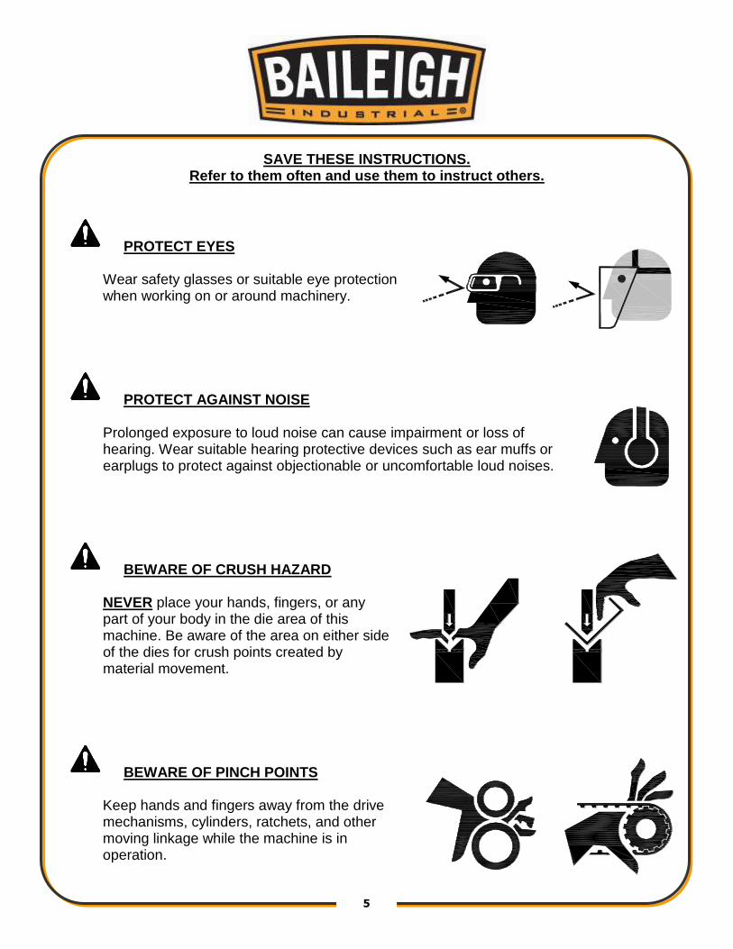
SAVE THESE INSTRUCTIONS. Refer to them often and use them to instruct others.
PROTECT EYES
Wear safety glasses or suitable eye protection when working on or around machinery.
PROTECT AGAINST NOISE
Prolonged exposure to loud noise can cause impairment or loss of hearing. Wear suitable hearing protective devices such as ear muffs or earplugs to protect against objectionable or uncomfortable loud noises.
BEWARE OF CRUSH HAZARD
NEVER place your hands, fingers, or any part of your body in the die area of this machine. Be aware of the area on either side of the dies for crush points created by material movement.
BEWARE OF PINCH POINTS
Keep hands and fingers away from the drive mechanisms, cylinders, ratchets, and other moving linkage while the machine is in operation.

6 6
KEEP CLEAR OF MOVING OBJECTS
Always be aware of the position of the material and the swing area in which the material will travel. The material will swing with significant force. This swing area will create pinch points and the force of the material movement may cause serious bodily injuries.
HYDRAULIC HOSE FAILURE
Exercise CAUTION around hydraulic hoses in case of a hose or fitting failure.
HIGH VOLTAGE
USE CAUTION IN HIGH VOLTAGE AREAS. DO NOT assume the power to be off. FOLLOW PROPER LOCKOUT PROCEDURES.

7 7
SAFETY PRECAUTIONS
Metal working can be dangerous if safe and proper operating procedures are not followed. As with all machinery, there are certain hazards involved with the operation of the product. Using the machine with respect and caution will considerably lessen the possibility of personal injury. However, if normal safety precautions are overlooked or ignored, personal injury to the operator may result. Safety equipment such as guards, hold-downs, safety glasses, dust masks and hearing protection can reduce your potential for injury. But even the best guard won’t make up for poor judgment, carelessness or inattention. Always use common sense and exercise caution in the workshop. If a procedure feels dangerous, don’t try it. REMEMBER: Your personal safety is your responsibility.
1. Only trained and qualified personnel can operate this machine.
2. Make sure guards are in place and in proper working order before operating machinery.
3. Remove any adjusting tools. Before operating the machine, make sure any adjusting tools have been removed.
4. Keep work area clean. Cluttered areas invite injuries.
5. Overloading machine. By overloading the machine you may cause injury from flying parts. DO NOT exceed the specified machine capacities.
6. Dressing material edges. Always chamfer and deburr all sharp edges.
7. Do not force tool. Your machine will do a better and safer job if used as intended. DO NOT use inappropriate attachments in an attempt to exceed the machines rated capacity.
8. Use the right tool for the job. DO NOT attempt to force a small tool or attachment to do the work of a large industrial tool. DO NOT use a tool for a purpose for which it was not intended.
9. Dress appropriate. DO NOT wear loose fitting clothing or jewelry as they can be caught in moving machine parts. Protective clothing and steel toe shoes are recommended when using machinery. Wear a restrictive hair covering to contain long hair.
10. Use eye and ear protection. Always wear ISO approved impact safety goggles. Wear a full-face shield if you are producing metal filings.
WARNING: FAILURE TO FOLLOW THESE RULES MAY RESULT IN
SERIOUS PERSONAL INJURY

8 8
11. Do not overreach. Maintain proper footing and balance at all times. DO NOT reach over or across a running machine.
12. Stay alert. Watch what you are doing and use common sense. DO NOT operate any tool or machine when you are tired.
13. Check for damaged parts. Before using any tool or machine, carefully check any part that appears damaged. Check for alignment and binding of moving parts that may affect proper machine operation.
14. Observe work area conditions. DO NOT use machines or power tools in damp or wet locations. Do not expose to rain. Keep work area well lighted. DO NOT use electrically powered tools in the presence of flammable gases or liquids.
15. Keep children away. Children must never be allowed in the work area. DO NOT let them handle machines, tools, or extension cords.
16. Store idle equipment. When not in use, tools must be stored in a dry location to inhibit rust. Always lock up tools and keep them out of reach of children.
17. DO NOT operate machine if under the influence of alcohol or drugs. Read warning labels on prescriptions. If there is any doubt, DO NOT operate the machine.
18. DO NOT touch live electrical components or parts.
19. Turn off power before checking, cleaning, or replacing any parts.
20. Be sure all equipment is properly installed and grounded according to national, state, and local codes.
21. DO NOT bypass or defeat any safety interlock systems.
22. Keep visitors a safe distance from the work area.

9 9
TECHNICAL SPECIFICATIONS
Maximum Center Line Radius (CLR)* 8" (203mm)
Minimum Center Line Radius (CLR)* .5" (12.7mm)
Minimum OD .25" (6.35mm)
Mild Steel Pipe (Schedule 40) Based on a maximum material tensile strength of 60000 PSI
2" (50.8mm)
Aluminum Pipe (Schedule 40) 2" (50.8mm)
Stainless Steel Pipe (Schedule 40) 1.5" (38.1mm)
Mild Steel Round Tube (Wall) 2.5" (.125) (63.5mm [3.175mm])
Aluminum Round Tube (Wall) 2.5" (.156) (63.5mm [3.96mm])
Stainless Steel Round Tube (Wall) 2.375" (.125) (60.325mm [3.175mm])
Chromolly Round Tube (Wall) 2" (.125) (50.8mm [3.175mm])
Mild Steel Solid Rod 1.25" (31.75mm)
Mild Steel Square Tube (Wall) 2" (.125) (50.8mm [3.175mm])
Power Supply 110VAC, 20A, 1ph, 60Hz
Sound level <70db
Shipping Weight (Lbs.) 700lbs. (318kg)
Shipping Dimensions (L x W x H) 68 x 60” x 44” (1727 x 1524 x 1118mm)
Based on a material tensile strength of *60000 PSI – mild steel
*CLR will vary based upon actual material and wall thickness.
TECHNICAL SUPPORT Our technical support department can be reached at 920.684.4990, and asking for the support desk for purchased machines. Tech Support handles questions on machine setup, schematics, warranty issues, and individual parts needs: (other than die sets and blades). For specific application needs or future machine purchases contact the Sales Department at: [email protected], Phone: 920.684.4990, or Fax: 920.684.3944.
Note: The photos illustrations used in this manual are representative only and may not depict the actual color, labeling or accessories and may be intended to illustrate technique only.
Note: The specifications and dimensions presented here are subject to change without prior notice due to improvements of our products.

10 10
UNPACKING AND CHECKING CONTENTS Your Baileigh machine is shipped complete in one crate. Separate all parts from the packing material and check each item carefully. Make certain all items are accounted for before discarding any packing material.
Cleaning
Your machine may be shipped with a rustproof waxy oil coating and grease on the exposed unpainted metal surfaces. To remove this protective coating, use a degreaser or solvent cleaner. For a more thorough cleaning, some parts will occasionally have to be removed. DO NOT USE acetone or brake cleaner as they may damage painted surfaces. Follow manufacturer’s label instructions when using any type of cleaning product. After cleaning, wipe unpainted metal surfaces with a light coating of quality oil or grease for protection.
WARNING: SUFFOCATION HAZARD! Immediately discard any plastic
bags and packing materials to eliminate choking and suffocation hazards to children and animals. If any parts are missing, do not plug in the power cable, or turn the power switch on
until the missing parts are obtained and installed correctly.
WARNING: DO NOT USE gasoline or other petroleum products to clean
the machine. They have low flash points and can explode or cause fire.
CAUTION: When using cleaning solvents work in a well-ventilated area.
Many cleaning solvents are toxic if inhaled.
GAS

11 11
TRANSPORTING AND LIFTING
Follow these guidelines when lifting:
• The lift truck must be able to lift at least 1.5 – 2 times the machines gross weight.
• Make sure the machine is balanced. While transporting, avoid rough or jerky motion, and maintain a safe clearance zone around the transport area.
• Use a fork lift with sufficient lifting capacity and forks that are long enough to reach the complete width of the machine.
• Remove the securing bolts that attach the machine to the pallet.
• Approaching the machine from the side, lift the machine on the frame taking care that there are no cables or pipes in the area of the forks.
• Move the machine to the required position and lower gently to the floor.
• Level the machine so that all the supporting feet are taking the weight of the machine and no rocking is taking place.
INSTALLATION
IMPORTANT:
Consider the following when looking for a suitable location to place the machine:
• Overall weight of the machine.
• Weight of material being processed.
• Sizes of material to be processed through the machine.
• Space needed for auxiliary stands, work tables, or other machinery.
• Clearance from walls and other obstacles.
• Maintain an adequate working area around the machine for safety.
• Have the work area well illuminated with proper lighting.
CAUTION: Lifting and carrying operations should be carried out by
skilled workers, such as a truck operator. Make sure the machine is well balanced. Choose a location that will keep the machine free from vibration and dust from other machinery. Keep in mind that having a large clearance area around the machine is
important for safe and efficient working conditions.
12 12
• Keep the floor free of oil and make sure it is not slippery.
• Remove scrap and waste materials regularly, and make sure the work area is free from obstructing objects.
• If long lengths of material are to be fed into the machine, make sure that they will not extend into any aisles.
• LEVELING: The machine should be sited on a level, concrete floor. For stationary machines, provisions for securing it should be in position prior to placing the machine. The accuracy of any machine depends on the precise placement of it to the mounting surface.
• FLOOR: This tool distributes a large amount of weight over a small area. Make certain that the floor is capable of supporting the weight of the machine, work stock, and the operator. The floor should also be a level surface. If the unit wobbles or rocks once in place, be sure to eliminate by using shims.
• WORKING CLEARANCES: Take into consideration the size of the material to be processed. Make sure that you allow enough space for you to operate the machine freely.
• POWER SUPPLY PLACEMENT: The power supply should be located close enough to the machine so that the power cord is not in an area where it would cause a tripping hazard. Be sure to observe all electrical codes if installing new circuits and/or outlets.
ASSEMBLY AND SET UP
1. Remove the machine from the skid it was shipped on and install the casters and wheels.
2. Check the oil level and top off if necessary.
3. Read through the remainder of the manual and become familiar with the die installation and settings as well as normal operation.
4. Position the machine as desired following the installation guidelines.
5. Follow the electrical guidelines to connect the machine to a power supply.
WARNING: For your own safety, DO NOT connect the machine to the
power source until the machine is completely assembled and you read and
understand the entire instruction manual.

13 13
GETTING TO KNOW YOUR MACHINE
A B
C
D
E F
H
I
J
K
L
G

14 14
Item Description Function
A Forward Foot Pedal Will operate the machine in the cw direction
B Reverse Foot Pedal Will operate the machine in the ccw direction
C Power Switch For turning power on/off to the bender
D Allen Wrench Used for adjusting and tightening the slide plate.
E Hydraulic Cylinders Supply the bending force to rotate the forming die.
F Upper Bend Angle Indicator Indicates the bend angle that the spindle is currently positioned at.
G Quick Release (shown with a counter die installed)
For pivoting counter die away from bend die to remove material quickly.
H Main Spindle And Drive Pins (shown with a square tube forming die installed)
For supporting and driving the forming die.
I Upper Bend Angle Scale A graduated scale plate used to indicates the bend angle that the spindle is currently positioned at.
J Grease Zerk For greasing main spindle bearing
K Lower Autostop Bend Angle Scale
A graduated scale plate which can rotate and be set to stop the bending at preset degrees of rotation of the spindle.
L Autostop Limit Switch (hidden) A roller limit switch which rides along the edge of the autostop bend angle scale which stops the bending rotation when the roller enters the scales detent.
GENERAL DESIGN DESCRIPTION You have made a practical choice in purchasing the RDB-150 Hydraulic Bending Machine. It has been carefully built of high quality materials and designed to give many years of efficient service. The simplicity of design and minimum effort required to operate the machine contributes towards meeting schedules and producing greater profits. The RDB-150 is an electric powered hydraulically operated “Rotary Draw” bending machine. To bend material, a bending die and counter die are required. The material is hooked by the bending dies’ hook arm and is powerfully rotated in the clockwise direction. As the bending die rotates, the counter die arm also rotates about the same axis, forcing the material to conform to the radius and shape of the bending die. The RDB-150 Bending Machine you have purchased is built of solid steel ensuring maximum rigidity. Tongue and groove design with grade 8 bolts throughout provides very high rigidity and stability. Throughout this manual are listed various safety-related descriptions for attention. These matters for attention contain the essential information to the operators while operating, and maintaining. Failure to follow these instructions may result in great damage to the machine or injury to the operator.
15 15
ELECTRICAL
Motor Specifications Your tool is wired for 110 volt, 60Hz alternating current. Before connecting the tool to the power source, make sure the machine is cut off from power source. Considerations
• Observe local electrical codes when connecting the machine.
• The circuit should be protected with a time delay fuse or circuit breaker with a amperage rating slightly higher than the full load current of machine.
• A separate electrical circuit should be used for your tools. Before connecting the motor to the power line, make sure the switch is in the “OFF” position and be sure that the electric current is of the same characteristics as indicated on the tool.
• All line connections should make good contact. Running on low voltage will damage the motor.
• In the event of a malfunction or breakdown, grounding provides a path of least resistance for electric current to reduce the risk of electric shock. This tool is equipped with an electric cord having an equipment-grounding conductor and a grounding plug. The plug must be plugged into a matching outlet that is properly installed and grounded in accordance with all local codes and ordinances.
CAUTION: HAVE ELECTRICAL UTILITIES CONNECTED TO MACHINE BY
A CERTIFIED ELECTRICIAN!
Check if the available power supply is the same as listed on the machine nameplate.
WARNING: Make sure the grounding wire (green) is properly connected
to avoid electric shock. DO NOT switch the position of the green grounding wire if
any electrical plug wires are switched during hookup.
WARNING: In all cases, make certain the receptacle in question is
properly grounded. If you are not sure, have a qualified electrician check the
receptacle.

16 16
• Improper connection of the equipment-grounding conductor can result in risk of electric shock. The conductor with insulation having an outer surface that is green with or without yellow stripes is the equipment-grounding conductor. If repair or replacement of the electric cord or plug is necessary, do not connect the equipment-grounding conductor to a live terminal.
• Check with a qualified electrician or service personnel if the grounding instructions are not completely understood, or if in doubt as to whether the tool is properly grounded.
• Repair or replace damaged or worn cord immediately.
Extension Cord Safety Extension cord should be in good condition and meet the minimum wire gauge requirements listed below:
LENGTH
AMP RATING 25ft 50ft 100ft
0-6 16 16 16
7-10 16 16 14
11-12 16 16 14
13-16 14 12 12
17-20 12 12 10
21-30 10 10 No
WIRE GAUGE
An undersized cord decreases line voltage, causing loss of power and overheating. All cords should use a ground wire and plug pin. Replace any damaged cords immediately.

17 17
OPERATION
Dry Running Machine
Before actually bending, several “dry runs” should be performed. This will remove any trapped air from the cylinders and hoses. Also, this will familiarize you with the controls and functions of the machine. To do this, follow the next steps. 1. Set the autostop dial to
approximately 220 degrees. If equipped.
2. With no material in the machine, press the forward foot peal until the hydraulic cylinders are fully extend and “deadheads”. Then press the reverse foot pedal until the hydraulic cylinders are fully retracted and “deadhead” in the home position. The overload relief valve will make a squealing noise when the cylinders “deadhead”; this is normal and will not hurt the function of the machine.
3. Repeat this sequence as many times as necessary (usually 5-6 full cycles) to remove any trapped air and to synchronize the cylinders.
4. The foot pedals have function to provide Forward and Reverse operation. The pedals are spring release and must be held in the Forward or Reverse positions to move the cylinders.
CAUTION: Always wear proper eye protection with side shields, safety
footwear, and leather gloves to protect from burrs and sharp edges.
CAUTION: Keep hands and fingers clear of the dies and swing arms.
Stand to the front of the machine to avoid getting hit with the material during the bending process. When handling large heavy materials make sure they are properly
supported.

18 18
DIE SELECTION AND INSTALLATION Before any bending can take place, the proper die set must be chosen to match the material being bent. (EX) 1-1/2” diameter tubing requires a die set marked 1-1/2” tube. A Hook Arm B Bend Die C Hold down Bolts D Plastic Slide E Counter Die Mount F Bronze Counter Die Insert G “0” Mark
Note: Pipe and Tube are not the same, (see table 1) for nominal pipe sizes. All BAILEIGH INDUSTRIAL dies are color coded to avoid confusion between pipe and tube (see table 2).
IMPORTANT: Damaged or worn tooling should be replaced before attempting to bend material. This will ensure that bends are correct and provide a longer life to machine components. When handling large heavy dies and/or material, make sure it is properly lifted and supported. 1. To install the die, slip the die over the centering pin until the three unequally spaced drive
pins engage the receiving holes formed in the die.
Note: The die will only fit one way. 2. When the drive pins line up the die will drop all the way down to the spindle.
3. Install and tighten the 1/2-13 socket head bolts provided with the die. Tighten these bolts enough to hold the die firmly down to the spindle. Approximately 30-40ft-lb. (40-50N•m).
IMPORTANT: FAILURE TO PROPERLY BOLT DOWN DIE WILL RESULT IN DAMAGE TO MACHINE AND TOOLING. BEND MATERAIL GREATER THAN CAPACITY WILL DAMGE THE MACHINE. THESE CONDITIONS ARE NOT COVER UNDER WARRANTY.
A
G F
B
C
D
E

19 19
H Spindle I Die Drive Pins J 1/2-13 Tapped holes for bolting down dies K Center Pin L Hitch Pin M Positioning Bolts 4. To install the counter die, remove the hitch pin and insert the counter die in the opening in
the counter die mount until the 3/4” holes line up.
5. Now insert the hitch pin through all the holes, reinstall clip on the hitch pin with the engraved side of the counter die facing up.
6. The counter die should be positioned approximately 1/8” (3mm) away from the die. This is accomplished by a combination of the slide plate position and changing between the two provided quick releases. See the Counterdie Placement Chart near the end of the manual.
7. In combination, install the recommended quick release (silver or gold) and then position the slide plate in the recommended holes.
8. Tighten the two socket head bolts to 200lbf ft. (27Nm).
IMPORTANT: The two 3/4-10 bolts hold the slide plate mechanism in place against the force generated during bending.
J
H
I
K L
M

20 20
Incorrect Counterdie Position
Too far away from die Touching die Correct Counter Die Position
Approximately 1/8” (3mm) away
IMPORTANT: Be sure the long end of the counter die points away from the hook arm, or to the right of machine.

21 21
Material Insertion
1. Once the die set is properly installed, the material that matches the die can be inserted (I.E.
1-1/4”tube would go into a die mark D-1250T-R***).
2. Open the counter die quick release assembly and insert the material past the hook arm. The start of bend mark is engraved with an “O” on the top of the die. Once the material is placed properly, the counter die slide block assembly can be tightened.
Inserting material to start Lubricating counter die bending
Important: Liberally apply lubricant along the counterdie and the 1/2 of the material that contacts the counter die (A) with a WD-40 style lubricant or equivalent. Do not lubricate the bending die. Lubricating the bending die will encourage slipping of material in the bending die. 3. Rotate the quick release counter die assembly until it firmly stops against its stop bolt. In
some cases usually with pipe the quick release will not close all the way. This is ok, as the forward foot pedal is activated the material will force its way into the die and bend properly.
A
22 22
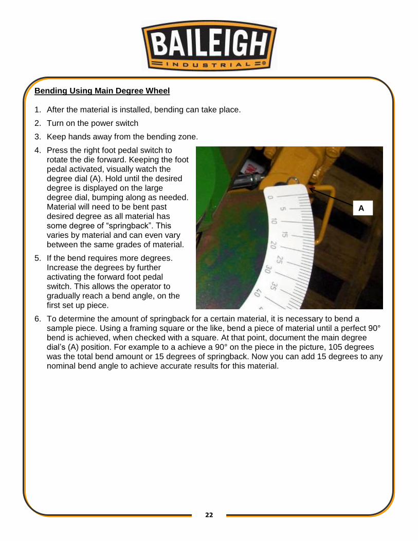
Bending Using Main Degree Wheel 1. After the material is installed, bending can take place.
2. Turn on the power switch
3. Keep hands away from the bending zone.
4. Press the right foot pedal switch to rotate the die forward. Keeping the foot pedal activated, visually watch the degree dial (A). Hold until the desired degree is displayed on the large degree dial, bumping along as needed. Material will need to be bent past desired degree as all material has some degree of “springback”. This varies by material and can even vary between the same grades of material.
5. If the bend requires more degrees. Increase the degrees by further activating the forward foot pedal switch. This allows the operator to gradually reach a bend angle, on the first set up piece.
6. To determine the amount of springback for a certain material, it is necessary to bend a sample piece. Using a framing square or the like, bend a piece of material until a perfect 90° bend is achieved, when checked with a square. At that point, document the main degree dial’s (A) position. For example to a achieve a 90° on the piece in the picture, 105 degrees was the total bend amount or 15 degrees of springback. Now you can add 15 degrees to any nominal bend angle to achieve accurate results for this material.
A

23 23
Using the auto stop feature – if equipped, (Setting the automatic stop position) The cylinders must be fully retracted and the main (top) degree dial must read “0”deg before setting the lower degree dial.
Note: Do not adjust the micro switch mounting bracket; this is preset from the factory. Use only the black Autostop adjusting knob to adjust the dial. 1. Method #1: Using the lower degree dial, set
the lower pointer to the desired degrees by loosening the black knob (A) and rotating the degree dial until the desired bend angle plus spring back is displayed (B).
2. Example: 105deg = 100deg bend, 5degrees of spring back.
3. Method #2: You can set the lower degree dial after a bend is complete also.
Example: Bend a piece of material to a desired angle using the top degree dial only. Once you are at the final bend position, Stop with the material still in the machine. Loosen and rotate the lower degree dial to “0” degrees (B). You will feel a definite click latching the dial in position; this is the spring loaded micro switch (C) holding the dial in position.
Note: The auto-stop feature only functions properly when the machine is bending material. The system needs pressure to function. You will not damage anything by running without material, as the micro switch is activated by the degree dial. The machine will hesitate and then continue, but will not stop unless you are bending material. 4. If the lower degree dial is set and the desired angle is more or less degrees than planned /
calculated for, simply advance or retard the lower degree dial to compensate for the difference.
A
C
B

24 24
Material Removal 1. After reaching the desired angle, the material needs to be removed.
2. Press the reverse (left) foot pedal. Both the die and the counter die will retract simultaneously. Run in reverse until all bending pressure is released from the bend.
Activating the quick release lever 3. Activate the quick release counter die lever (A) and completely remove the material.
4. After the material is safely removed, press the reverse (left) foot pedal keeping hands clear until both cylinders fully retract.
5. The machine is now at the “home” position and can be reloaded for the next bend.
6. Repeat previous steps.
A
25 25
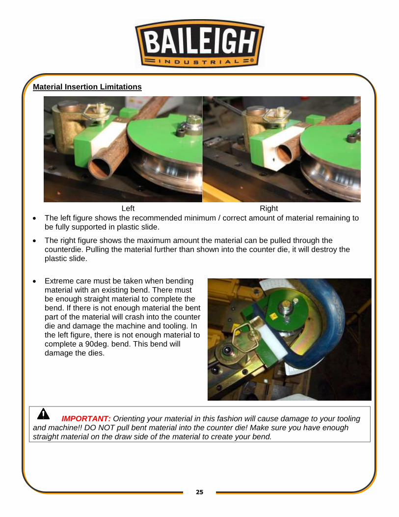
Material Insertion Limitations
Left Right
• The left figure shows the recommended minimum / correct amount of material remaining to be fully supported in plastic slide.
• The right figure shows the maximum amount the material can be pulled through the counterdie. Pulling the material further than shown into the counter die, it will destroy the plastic slide.
• Extreme care must be taken when bending material with an existing bend. There must be enough straight material to complete the bend. If there is not enough material the bent part of the material will crash into the counter die and damage the machine and tooling. In the left figure, there is not enough material to complete a 90deg. bend. This bend will damage the dies.
IMPORTANT: Orienting your material in this fashion will cause damage to your tooling and machine!! DO NOT pull bent material into the counter die! Make sure you have enough straight material on the draw side of the material to create your bend.

26 26
Bending More than 180 Degrees
• This machine is capable of bending more than 180 degrees. Contact Baileigh Industrial about your application.
o It will require a password to make the machine go past 200 degrees.
o Requires special tooling to allow removal of bent part. If standard tooling is used, the material will be locked onto the die.
UNDERSTANDING SPRINGBACK Springback can be difficult to understand. As material is bent, the materials yield strength resists being formed. As a final degree is reached, the machine will have enough power to hold the bend at a set degree, but as the pressure of the machine is released, the material has a resistance built in, so it “springs back” Springback will vary with every size, type and wall thickness, so it will never be consistent from size to size. The best way to determine a materials springback is to do sample bends to 90 degrees until a perfect 90 is obtained.
• At that point document the actual machine degrees.
• Full manual mode is the best place to do these tests.
• Use the overbend amount and enter that value into the springback field.
MATERIAL SELECTION
When selecting materials keep these instructions in mind:
• Material must be clean and dry. (without oil)
• Material should have a smooth surface so it processes easily.
• Dimensional properties of material must be consistent and not exceed the machine capacity values.
• Chemical structure of material must be consistent.
• Buy certificated steel from the same vendor when possible.
CAUTION: It must be determined by the customer that materials being
processed through the machine are NOT potentially hazardous to operator or personnel working nearby.

27 27
Material Layout In order to create accurate parts, you will have to layout the material in flat form. First you will need to determine how much material is used per degree of bend. Use the multiplier table on Table #3 to determine the arc lengths for the die in use. Or use the following formula: Alternate arc length formula: Example: 6.0 clr x2=12 12x3.14=37.699 37.699/360=0.1047” per degree 0.1047x 90 degrees =9.425” of material used for a 90 degree bend. Once the arc lengths are determined you can begin layout of the material using Diagram #1 as a reference.
• Diagram #1 shows a simple part bent on the same plane in the same direction.
• Diagram #2 shows bending based off of a centerline in two directions.
• For symmetrical bends, centerline bending is easiest.
• For non-symmetrical bends, continuous one direction bending is best.
• Another way to layout material is to draw them in a 2D computer software program like Auto Cad. There are many free programs on the internet. In a 2D program you will draw the parts centerline only with corresponding clr’s. Then you will be able to list individual segments of the bent part. This data can be directly entered into the control.
• Another program available is BEND-TECH which is a program specifically designed for tube bending and will give you all of the required data to make a part. This software is available from Baileigh Industrial.
• Bending with a rotary draw bender requires determining the start of bend point which will line up with the “0” mark on the die. The portion of the tube toward the hook arm will be locked to the die, the portion toward the counter die is the draw side and will slide along the counter die and conform to the dies shape/radius.

28 28
PIPE AND TUBE BENDING DIAGRAMS L = Arc length (outside) R = Rise (inside) D = Tube outside diameter t = Tube wall thickness a = First bend arc angle H = Height of offset b = Second bend arc angle L = Length of offset A = First tangent R1 = First radius B = Straight between bends R2 = Second radius C = Second tangent t = Tube Wall Thickness D = Tube outside diameter

29 29
BENDING GLOSSARY
Arc Length The length of material along the centerline of the tubing
Centerline Radius (CLR) Distance in inches from the center of curvature to the centerline axis of the tube bending or pipe bending bends. Abbreviated as CLR. See Tube Bending and Pipe Bending Diagram
Degree Angle in degrees to which the tube/pipe bends are formed (i.e. 45 degrees, 90 degrees, 180 degrees, etc.)
Easy Way (EW) Bending of a rectangular tube with its short side in the plane of the tube or pipe bend
Hard Way (HW) Bending of a rectangular tube with its long side in the plane of the tube or pipe bend
I.D. Inside diameter of the tube or pipe bends
Minimum Tangent The minimum straight on the end of pipe bends required by the bending machine to form the bend
Neutral Axis That portion of the pipe or tube that is neither in compression or tension.
O.D. Outside diameter in inches of the tube or pipe
Out of Plane The deviation of the horizontal plane of a single pipe bend between its tangent points, based on the theoretical center-line of the pipe bend
Ovality The distortion or flattening of pipe or tube from its normal, round shape caused by the pipe bending process
Springback Amount of degrees material will return after bending pressure is released
Tangent The straight portion of material on either side of arc of bending bends. See Tube Bending and Pipe Bending Diagrams.
Tangent Point The point at which the bend starts or ends. See Tube Bending and Pipe Bending Diagrams.
Wall The thickness in inches of tubular pipe bending material.
Wrinkles Waving or corrugation of pipe bending bends in the inner radius.

30 30
BENDING SUGGESTIONS Die Types and Bend Results
Standard Elliptical
• Meant to get thinner wall tubing, to a tighter radius, without the tube collapsing.
• Function over form
• This die will distort the tubing
Standard Elliptical with Revised Counter Die
• “Middle ground” die configuration
• Wont bend as tight of a radius as the standard elliptical die, but will bend tighter than the true radius
• Less distortion, but still visible (as compared to the standard elliptical die configuration)
True Radius
• Minimal to no distortion
• Aesthetically pleasing bend
• Needs larger radius to bend without collapsing (as compared to the other two configurations)
Aluminum Bending
If bending aluminum, lubrication is very important, if the results are less than desirable with WD-40 other lubricants can be used such as:
• Johnson Paste Wax (seems to work the best)
• High Pressure grease
• Highly rich dish soap
• The bronze counter die must be polished and have no aluminum deposits or it will continue to pick up metal.
• If using BAILEIGH INDUSTRIAL’s standard counterdie is not producing desired results, roller counter dies are also available.
• BAILEIGH INDUSTRIAL has both steel rollers as well as plastic rollers. Plastic rollers are used primarily for polished aluminum. Steel rollers would be used for non-polished materials.
• Some aluminum will crack as it is being bent, 6061-T6 is very hard and may need to be annealed or ordered in the “T-0” condition. Aluminum will age harden so if possible try to get freshly run material.

31 31
Heavy Wall DOM tubing
If heavy wall materials are bent to a tight radius, they can tend to slip in the hook arm causing a poor bend result, below are some suggestions
• Use a vise clamp on the outside of the hook arm to “lock” the material in place.
• Use a piece of two sided coarse emery cloth in between the hook arm and the material, this works very well.
• In only this application, high pressure grease applied to the DIE GROOVE also helps.
• BAILEIGH INDUSTRIAL can make special clamps to hold material in place.
Bending With Square Dies
• Die Parts
1 Main Bending Die 2 Die Cap 3 Quick Release Handles 4 Hook-Arm 5 Hook-Arm Clamp 6 Plastic Slide 7 Slide Mount 8 Quick Release Studs Square Tooling Setup
1. Install the bending die (1) on to the spindle. Be careful not to pinch your fingers as you lower the die on to the spindle. The die will only fit on the spindle one way. Bolt the die to the spindle using the holes in the die.
2. Install the plastic counter die assembly (6, 7) with the long end pointing away from the hook arm.
3. Snug up the cap clamps (3). Do not over tighten! Or they will be overly difficult to loosen after the bend is complete. Note: tighten clamps without material in the die. The clamps are lift and turn, so you can position them anywhere. This allows the handles to clear the counter-die mount during bending.

32 32
4. Insert the material in to the hook arm (4) and pull in to the die. It may be a tight fit. Continue to pull until the material is fully seated in the die’s groove.
5. Lube the counter die and the material that will slide along the counter die. Bring the plastic counter die assembly up to the material, leaving about 1/8” to 1/4" gap. (Note: on some thinner material it helps to keep the counter die approx. 1” away from the material)
IMPORTANT: Do not lube the bending die surfaces. This will increase the possibility for slippage. Make sure all the die cap clamp handles (3) are inside the die diameter. They could catch the counter die mounting assembly and break off. 6. If the material slips during the bending operation, install the hook arm clamp (5). Do not use
it unless you have to.
7. Activate the bender and bend to the desired angle.
8. To remove the material, open the counter die and return bender to the “home position”. Using a soft mallet, gently tap the cap clamps open and the material will spring out of the die (1). Remove the material and re-snug the cap clamps.
9. Install the next piece of material to be bent and repeat these steps.
Large Size Square
When bending larger than 1.5” (38.1mm) thinner wall square tubing, the counter die position seems to work better between 1/2" and 1” (12.7-25.4mm) farther away from the die. This seems do reduce side wall distortion and inner wrinkling. Although this suggestion is to help on large size, the same steps can be used for any square, if trying to achieve better results. If the square material slips in the hook arm, use the supplied clamp and bolts to hold in place. BAILEIGH INDUSTRIAL offer crush bend dies to form a concave crease on the inside of square bends to reduce the possibility of wrinkling.

33 33
LUBRICATION AND MAINTENANCE
• Check daily for any unsafe conditions and fix immediately.
• Check that all nuts and bolts are properly tightened.
• On a weekly basis clean the machine and the area around it.
• Lubricate threaded components and sliding devices.
• Apply rust inhibitive lubricant to all non-painted surfaces.
Note: Proper maintenance can increase the life expectancy of your machine.
• The fluid level in the power unit’s reservoir should be checked monthly. If the level is below 1/2 full, fill to the top with AW-46 hydraulic fluid. Hydraulic fluid and the filter should be changed when the filter gauge reads “Change Filter”.
• Check periodically for leaks. If a leak is detected, consult Baileigh Industrial.
• There are four grease zerks on the machine, at the main spindle pivots. Grease these zerks every month with only two pumps from a standard grease gun.
• Check for any loose or worn parts
• If hoses or fittings are replaced, they must be rated for 4000psi (275 bars, 282 kg/cm).
WARNING: Make sure the electrical disconnect is OFF before working on
the machine. Maintenance should be performed on a regular basis by qualified personnel.
Always follow proper safety precautions when working on or around any machinery.
34 34
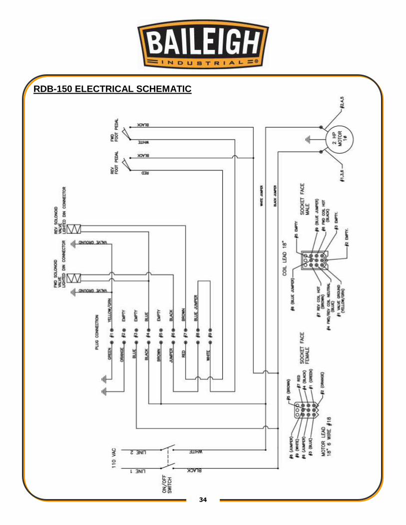
RDB-150 ELECTRICAL SCHEMATIC

35 35
RDB-150-AS ELECTRICAL SCHEMATIC

36 36
HYDRAULIC DIAGRAM

37 37
TROUBLESHOOTING
Problem Solution
Cylinders not retracting all the way or not in sequence
Do the dry run sequence as outlined in section 8 of the manual under operation
Machine doesn't move forward or moves forward slowly and does not build up pressure
Check to make sure the autostop dial has the micro switch roller riding on the outside of the perimeter of the dial. The micro switch must be depressed for the machine to work, if the roller is in the detent position or not inline with the autostop dial the machine will be in the stop position. Tighten autostop adjusting knob until the autostop dial plate comes into the same plane as the micro switch roller.
Incorrect autostop switch position
Check that the solenoid valve has its wires connected. To Check it's functionality extend the cylinder all the way, let the machine deadhead and build up pressure approximately 2000 (Psi). At that point rotate the autostop dial the detent position and the pressure should drop to "0" Psi.
Solenoid switch
Machine doesn't bend at pressure (2000 Psi)
If trying to bend material and the machine builds up pressure and stalls this usually means: The material is too thick, the material has too high of a yield strength, or the material is over the machines capacity.
WARNING: Make sure the electrical disconnect is OFF before working on
the machine.

38 38
Material slips in the hookarm
Too much lube on material and is transferring to the bend die clean the bend die with degreaser.
The counter die should be lubed only
The material may need to be clamped
Wrong material for the die set
Spindle drive pins are damaged If the bend dies are not bolted down properly the drive pins will get damaged. Replace drive pins.
Poor Bend Results
Check proper tooling for material IE Pipe Vs Tube. Green for pipe, Blue for tube, Red for metric and Gray for square or rectangle tubing. See pipe sizing chart
Wall thickness is too thin

39 39
TABLES, CHARTS, & DIAGRAMS Table 1 Standard Pipe Sizes and Schedules
PIPE SIZES
O.D. Pipe Schedules and Wall Thickness
5 10 40 80 160 XX STRONG
1/8 0.405 0.400 0.050 0.068 0.095
1/4 0.540 0.500 0.070 0.088 0.119
3/8 0.675 0.500 0.070 0.091 0.126
1/2 0.840 0.700 0.080 0.109 0.147 0.188 0.294
3/4 1.050 0.700 0.080 0.113 0.154 0.219 0.308
1 1.315 0.700 0.110 0.133 0.179 0.250 0.358
1-1/4 1.660 0.700 0.110 0.140 0.191 0.250 0.382
1-1/2 1.900 0.700 0.110 0.145 0.200 0.281 0.400
2 2.375 0.700 0.110 0.154 0.218 0.344 0.436
2-1/2 2.875 0.800 0.120 0.203 0.276 0.375 0.552
Table 2 Die Color Code Chart
Material Color
Pipe Green
Tube Blue
Metric Red
Square or Rectangle Gray

40 40
Table 3 ARC LENGTH TABLE EXAMPLE: Arc Length = Constant x Bend Radius. Example: 90deg bend with 6” clr EXAMPLE: 1.575 (from table) x 6” (clr) = 9.45” (Arc Length) For bends more than 90deg, Constants can be added together.
Degrees Constant Degrees Constant Degrees Constant
1 0.0175 31 0.5410 61 1.0645
2 0.0349 32 0.5584 62 1.0819
3 0.0524 33 0.5759 63 1.0994
4 0.0698 34 0.5933 64 1.1168
5 0.0873 35 0.6108 65 1.1343
6 0.1047 36 0.6282 66 1.1517
7 0.1222 37 0.6457 67 1.1692
8 0.1396 38 0.6631 68 1.1866
9 0.1571 39 0.6806 69 1.2041
10 0.1745 40 0.6980 70 1.2215
11 0.1920 41 0.7155 71 1.2390
12 0.2094 42 0.7329 72 1.2564
13 0.2269 43 0.7504 73 1.2739
14 0.2443 44 0.7678 74 1.2913
15 0.2618 45 0.7853 75 1.3088
16 0.2792 46 0.8027 76 1.3262
17 0.2967 47 0.8202 77 1.3437
18 0.3141 48 0.8376 78 1.3611
19 0.3316 49 0.8551 79 1.3786
20 0.3490 50 0.8725 80 1.3960
21 0.3665 51 0.8900 81 1.4135
22 0.3839 52 0.9074 82 1.4309
23 0.4014 53 0.9249 83 1.4484
24 0.4188 54 0.9423 84 1.4658
25 0.4363 55 0.9598 85 1.4833
26 0.4537 56 0.9772 86 1.5007
27 0.4712 57 0.9947 87 1.5182
28 0.4886 58 1.0121 88 1.5356
29 0.5061 59 1.0296 89 1.5531
30 0.5235 60 1.0470 90 1.5705
41 41
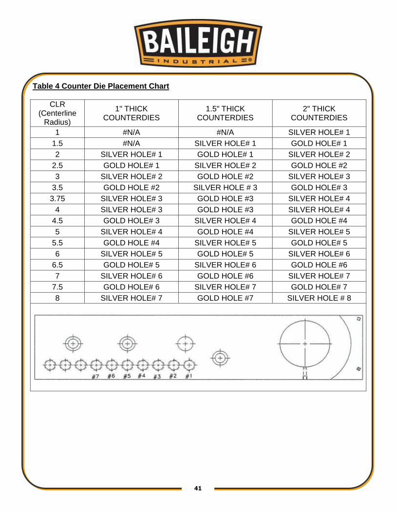
Table 4 Counter Die Placement Chart
CLR (Centerline
Radius)
1" THICK COUNTERDIES
1.5" THICK COUNTERDIES
2" THICK COUNTERDIES
1 #N/A #N/A SILVER HOLE# 1
1.5 #N/A SILVER HOLE# 1 GOLD HOLE# 1
2 SILVER HOLE# 1 GOLD HOLE# 1 SILVER HOLE# 2
2.5 GOLD HOLE# 1 SILVER HOLE# 2 GOLD HOLE #2
3 SILVER HOLE# 2 GOLD HOLE #2 SILVER HOLE# 3
3.5 GOLD HOLE #2 SILVER HOLE # 3 GOLD HOLE# 3
3.75 SILVER HOLE# 3 GOLD HOLE #3 SILVER HOLE# 4
4 SILVER HOLE# 3 GOLD HOLE #3 SILVER HOLE# 4
4.5 GOLD HOLE# 3 SILVER HOLE# 4 GOLD HOLE #4
5 SILVER HOLE# 4 GOLD HOLE #4 SILVER HOLE# 5
5.5 GOLD HOLE #4 SILVER HOLE# 5 GOLD HOLE# 5
6 SILVER HOLE# 5 GOLD HOLE# 5 SILVER HOLE# 6
6.5 GOLD HOLE# 5 SILVER HOLE# 6 GOLD HOLE #6
7 SILVER HOLE# 6 GOLD HOLE #6 SILVER HOLE# 7
7.5 GOLD HOLE# 6 SILVER HOLE# 7 GOLD HOLE# 7
8 SILVER HOLE# 7 GOLD HOLE #7 SILVER HOLE # 8

42 42
Diagram 1

43 43
Diagram2
44 44
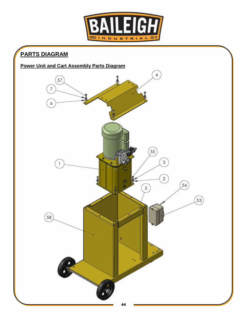
PARTS DIAGRAM Power Unit and Cart Assembly Parts Diagram

45 45
Main Tube and Cylinders Assembly Parts Diagram

46 46
Swing Arm Assembly Parts Diagram

47 47
Degree Dials Parts Diagram
48 48
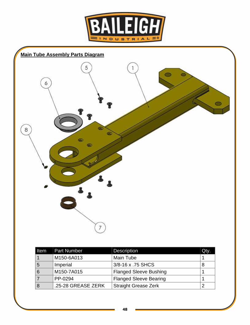
Main Tube Assembly Parts Diagram
Item Part Number Description Qty.
1 M150-6A013 Main Tube 1
5 Imperial 3/8-16 x .75 SHCS 8
6 M150-7A015 Flanged Sleeve Bushing 1
7 PP-0294 Flanged Sleeve Bearing 1
8 .25-28 GREASE ZERK Straight Grease Zerk 2

49 49
Cart Assembly Parts Diagram
Item Part Number Description Qty.
1 M150-5A014 Upright, Base 1
3 PP-0035 1" Set Screw Collar 4
5 PP-0064 8" Rubber Wheel 2
6 PP-0043 1.0 ID x 1.1875 OD x 0.75 Lg Bushing 4
7 PP-0048 4.0 Inch Caster 2
8 Imperial 3/8-16 x 1 Carriage Bolt 8
9 Imperial 3/8 Flatwasher 8
10 Imperial 3/8 Lockwasher 8
11 Imperial 3/8-16 Nut 7

50 50
Parts List
Item Part Number Description Qty.
1 Power Unit Assembly M150 Power Unit Assembly 1
2 Imperial 5/16 Flat Washer 4
3 Imperial 5/16 Lockwasher 4
4 M175-6A016 Riser 1
5 M150-6A035 Cross Bar 1
6 Imperial 3/8 Flatwasher 8
7 Imperial 3/8 Lockwasher 16
8 M150-5A006 Main Tube Assembly 1
9 PP-1430 17mm Hex Key 1
10 PP-1494 20 Mm Set Screw Collar 1
11 PP-0403 3 X 12 Hydraulic Cylinder 2
12 PP-0403-J Pin 3
13 PP-0403-K Hairclip 6
14 ME-M150-5A005 Torque Arm (Metric) 1
15 M150-6A019 5/8 Drive Key 1
16 ME-M150-6A052 Top Pivot Bar (Metric) 1
17 M150-7A014 Top Bushing 1
18 .25-28 GREASE ZERK Straight Grease Zerk 2
19 PP-1071 3/4" Dowel Pin 3
20 ME-M300-7A003 Center Pin 1
21 M12 X 1.75 X 50 SHCS 2
22 ME-M150-7A011 Spacer Shaft (Metric) 1
23 ME-M175-6A004 Tie Bar (Short Metric) 1
24 ME-M175-6A008 Tie Bar (Long Metric) 1
25 ME-M175-6A012 Lower Pivot Plate (Metric) 1
26 PP-0295 Flanged Sleeve Bearing 1
27 PP-0293 2.0 Split Clamp Collar 1
28 M16 X 2.0 X 40 SHCS 2
29 M12 X 1.75 X 30 SHCS 10
30 M175-6A010 Auto Stop Pointer 1
31 M6 X 1.0 X 12 Button Head 4
32 ME-M150-5A008 Switch Mount (Metric) 1
33 M6 X 1.0 X 14 Hex Flange 2

51 51
Item Part Number Description Qty.
34 ME-M150-5A016 Pivot Assembly (Metric) 1
35 M20 X 2.5 X 160 SHCS 1
36 M20 X 2.5 X 45 SHCS 1
37 ME-M175-7A005 Spindle 1
38 M175-7A004 Cylinder Pin (Long) 1
39 PP-0035 1" Set Screw Collar 7
40 ME-M150-6A020 Pointer Block (Metric) 1
41 M6 X 1.0 X 25 SHCS 1
42 M150-6A029 Auto Stop Sticker 1
43 PP-0136 Auto-Stop 1
44 M175-6A017 Adhesive Backed Degree Dial 1
45 M175-6A007 Top Degree Dial Backing Plate 1
46 M175-6A018 M175 Pointer 1
47 M5 X 0.8 X 6 Set Screw 1
48 M150-5A001 Gold Quick Release 1
49 M150-5A011 Silver Quick Release 1
50 PP-0413 Auto-Stop Knob 1
51 M6 X 1.0 X 30 SHCS 2
52 PP-0853 Elbow 4
53 PP-1294 European ON/OFF Switch 1
54 M4 X 0.7 X 10 SHCS 2
55 Imperial 5/16-18 X .75 HHCS 4
57 Imperial 3/8-16 X 1 HHCS 8
57 Imperial M20 X 2.5 X 110 SHCS 1

52 52
NOTES

53 53
BAILEIGH INDUSTRIAL, INC. 1625 DUFEK DRIVE MANITOWOC, WI 54220 PHONE: 920. 684. 4990 FAX: 920. 684. 3944
www.baileigh.com
BAILEIGH INDUSTRIAL, INC. 1455 S. CAMPUS AVENUE ONTARIO, CA 91761 PHONE: 920. 684. 4990 FAX: 920. 684. 3944
BAILEIGH INDUSTRIAL LTD. UNIT 1 FULLWOOD CLOSE ALDERMANS GREEN INDUSTRIAL ESTATE COVENTRY, CV2 2SS UNITED KINGDOM
PHONE: +44 (0)24 7661 9267 FAX: +44 (0)24 7661 9276 WWW.BAILEIGHINDUSTRIAL.CO.UK
BAILEIGH INDUSTRIAL PTY. LTD. P.O BOX 1573, 126 MELROSE DRIVE TULLAMARINE,
VIC 3043 AUSTRALIA WWW.BAILEIGHINDUSTRIAL.COM.AU