operator’s manualassets.mbusa.com/vcm/cac_rapmd/08to12maybachownersmanua… · therefore,...
TRANSCRIPT

O P E R A T O R ’ S M A N U A L
Grafik in der Größe 216x79 mmin den Grafikrahmen importieren!
Order No. 6515 4446 13 Part No. 240 584 38 82 USA Edition B 2007 OP
ER
AT
OR
’S M
AN
UA
LM
AY
BA
CH
Service and Literature
Your authorized Maybach Studio has trained technicians and Genuine Maybach Parts to service your vehicle properly. For expert advice and quality service, contact your authorized Maybach Studio.
If you are interested in obtaining service literature for your vehicle, please contact your authorized Maybach Studio. We consider this the best way for you to obtain accurate information for your vehicle.
For further information you can find us on the Maybach web-site www.maybach-manufaktur.com or www.maybach.ca.
We reserve the right to make changes in design and equipment. Therefore, information, illustrations and descriptions in this Operator's Manual might differ from your vehicle.
Reprinting, translation and copying, even of excerpts, is not permitted without our prior authorization in writing.
Press time November 13, 2006GSP/TID
Printed in Germany
Warning! G
To help avoid personal injury, be extremely careful when performing any service work or repairs. Improper or incomplete service or the use of incorrect or inappropriate parts or materials may damage the vehicle or its equipment, which may in turn result in personal injury.
If you have questions about carrying out any type of service, turn to the advice of an authorized Maybach Studio.

Maybach 57Maybach 62Maybach 57 SMaybach 62 S

Our company congratulates you on the purchase of your new Maybach.
Your selection of our product is a dem-onstration of your trust in Maybach Manufaktur. Furthermore, it exemplifies your desire to own an automobile that will be as easy as possible to operate and provide years of service.
Your Maybach represents the efforts of many skilled engineers and craftsmen. To help assure your driving pleasure and also the safety of you and your passen-gers, we ask you to make a small invest-ment of your time:
� Please read this manual carefully, then return it to your vehicle where it will be handy for your reference.
� Please follow the recommendations contained in this manual. They are designed to acquaint you with the operation of your Maybach.
� Please pay attention to the warnings and cautions contained in this manu-al. They are designed to help improve the safety of the vehicle operator and occupants.
� Should you have any questions, please contact your Maybach Studio MRM (Maybach Relationship Manager) or call us at 1-866-FOR-MAYBach (in the USA) or 1-888-881-6611 (in Canada).
We extend our best wishes for many miles of safe, pleasurable driving.
Mercedes-Benz USA, LLC A DaimlerChrysler Company

Contents
Introduction . . . . . . . . . . . . . . . . . . . . . 9Product information. . . . . . . . . . . . . . . 9Operator’s Manual . . . . . . . . . . . . . . . 10
Service and warranty information 10Important notice for California retail buyers and lessees of Maybach automobiles . . . . . . . . . 11Maintenance . . . . . . . . . . . . . . . . . 11Roadside Assistance . . . . . . . . . . . 12Change of address or ownership . 12Operating your vehicle outside the USA or Canada . . . . . . . . . . . . 12
Where to find it . . . . . . . . . . . . . . . . . 13Symbols . . . . . . . . . . . . . . . . . . . . . . . . 14Operating safety. . . . . . . . . . . . . . . . . 15
Proper use of the vehicle . . . . . . . 15Problems with your vehicle . . . . . . . . 16Reporting safety defects . . . . . . . . . . 17
Reporting safety defects . . . . . . . 17Vehicle data recording. . . . . . . . . . . . 18
Information regarding electronic recording devices. . . . . 18
At a glance . . . . . . . . . . . . . . . . . . . . . . 19Cockpit . . . . . . . . . . . . . . . . . . . . . . . . . 20Instrument cluster . . . . . . . . . . . . . . . . 22Multifunction steering wheel . . . . . . . 24Front center console . . . . . . . . . . . . . . 25
Upper part . . . . . . . . . . . . . . . . . . . 25Lower part . . . . . . . . . . . . . . . . . . . 26
Overhead control panel . . . . . . . . . . . 28Driver’s door control panel . . . . . . . . . 29Rear passenger compartment . . . . . . . 30
Maybach 57 (vehicles without rear center seat*) . . . . . . . . . . . . . . 30Maybach 57 (vehicles with rear center seat*) . . . . . . . . . . . . . . . . . 32Maybach 62 without partition* . . 34Maybach 62 with partition* . . . . . 36
Rear seats . . . . . . . . . . . . . . . . . . . . . . . 38Maybach 57 (vehicles without rear center seat*) . . . . . . . . . . . . . . 38Maybach 57 (vehicles with rear center seat*) . . . . . . . . . . . . . . . . . . 40Maybach 62 (vehicles without rear center seat*) . . . . . . . . . . . . . . 42Maybach 62 (vehicles with rear center seat*) . . . . . . . . . . . . . . . . . . 44
Rear center console. . . . . . . . . . . . . . . 46Maybach 57 (vehicles without rear center seat*). . . . . . . . . . . . . . 46Maybach 57 (vehicles with rear center seat*) . . . . . . . . . . . . . . . . . 47Maybach 62 with power tilt/sliding sunroof (vehicles without rear center seat*) . . . . . . 48Maybach 62 with power tilt/sliding sunroof (vehicles with rear center seat*). . . . . . . . . . . . . . 49Maybach 62 with electrotransparent roof*(vehicles without rear center seat*) . . . . . . . . . . . . . . . . . . . . . . . 51Maybach 62 with electrotransparent roof* (vehicles with rear center seat*). . 52
Rear door control panel . . . . . . . . . . . 54Maybach 57 . . . . . . . . . . . . . . . . . . 54Maybach 62 . . . . . . . . . . . . . . . . . . 55

Contents
Getting started . . . . . . . . . . . . . . . . . . 57Unlocking . . . . . . . . . . . . . . . . . . . . . . 58
Unlocking with the SmartKey . . . 58Unlocking with KEYLESS-GO** . . 59Starter switch positions. . . . . . . . . 60
Adjusting . . . . . . . . . . . . . . . . . . . . . . . 62Seats . . . . . . . . . . . . . . . . . . . . . . . 62Steering wheel . . . . . . . . . . . . . . . 64Mirrors . . . . . . . . . . . . . . . . . . . . . . 66
Driving . . . . . . . . . . . . . . . . . . . . . . . . . 68Fastening the seat belts . . . . . . . . 68Starting the engine. . . . . . . . . . . . 70Parking brake . . . . . . . . . . . . . . . . 72Driving off . . . . . . . . . . . . . . . . . . . 73Switching on headlamps. . . . . . . . 73Turn signals . . . . . . . . . . . . . . . . . . 74Windshield wipers. . . . . . . . . . . . . 74Problems while driving . . . . . . . . . 76
Parking and locking . . . . . . . . . . . . . . 77Parking brake . . . . . . . . . . . . . . . . 77Switching off headlamps . . . . . . . 78Turning off the engine . . . . . . . . . 78Releasing seat belts. . . . . . . . . . . . 79Locking . . . . . . . . . . . . . . . . . . . . . 79
Safety and Security . . . . . . . . . . . . . . . 81Occupant safety . . . . . . . . . . . . . . . . . . 82
Airbags . . . . . . . . . . . . . . . . . . . . . . 83Occupant Classification System . . . 88Seat belts. . . . . . . . . . . . . . . . . . . . . 92Children in the vehicle . . . . . . . . . . 95Override switch for rear passenger compartment . . . . . . . 100
Panic alarm . . . . . . . . . . . . . . . . . . . . . 102Activating . . . . . . . . . . . . . . . . . . . 102Deactivating . . . . . . . . . . . . . . . . . 102
Driving safety systems . . . . . . . . . . . . 103ABS . . . . . . . . . . . . . . . . . . . . . . . . 103BAS . . . . . . . . . . . . . . . . . . . . . . . . 104ESP® . . . . . . . . . . . . . . . . . . . . . . . . 105Electro-hydraulic brake system . . 107
Anti-theft systems . . . . . . . . . . . . . . . 110Immobilizer. . . . . . . . . . . . . . . . . . 110Anti-theft alarm system . . . . . . . . 110Tow-away alarm . . . . . . . . . . . . . . 111
Controls in detail . . . . . . . . . . . . . . . . 113Locking and unlocking . . . . . . . . . . . 114
SmartKey . . . . . . . . . . . . . . . . . . . 114 SmartKey with KEYLESS-GO**. . 117Checking batteries in the SmartKey or SmartKey with KEYLESS-GO** . . . . . . . . . . . . . . . 121Loss of the SmartKey or SmartKey with KEYLESS-GO** . . 121Opening the doors from the inside . . . . . . . . . . . . . . . . . . . . . . 122Closing the rear doors automatically from the inside (Maybach 62) . . . . . . . . . . . . . . . . 123Opening the trunk. . . . . . . . . . . . 123Closing the trunk . . . . . . . . . . . . . 124Trunk emergency release . . . . . . 127Valet trunk . . . . . . . . . . . . . . . . . . 127Power closing assist for doors and trunk lid . . . . . . . . . . . . . . . . 128Automatic central locking. . . . . . 129Locking and unlocking from the inside . . . . . . . . . . . . . . . . . . . 129
Seats . . . . . . . . . . . . . . . . . . . . . . . . . . 131Rear seats . . . . . . . . . . . . . . . . . . . 131Setting front passenger seat position from rear . . . . . . . . . . . . 135Multicontour seats. . . . . . . . . . . . 136

Contents
Seat heating . . . . . . . . . . . . . . . . 138Seat ventilation*. . . . . . . . . . . . . 139
Memory function . . . . . . . . . . . . . . . 140Storing positions in memory . . . 141Recalling positions from memory . . . . . . . . . . . . . . . . . . . . 141Storing exterior rear view mirror parking position . . . . . . . 141
Lighting. . . . . . . . . . . . . . . . . . . . . . . 142Exterior lamp switch . . . . . . . . . . 142Combination switch . . . . . . . . . . 145Corner-illuminating lamps . . . . . 146Hazard warning flasher . . . . . . . 147Interior lighting in the front . . . 148Interior lighting in the rear . . . . 149Courtesy lighting . . . . . . . . . . . . 153Door entry lamps . . . . . . . . . . . . 153Trunk lamp . . . . . . . . . . . . . . . . . 153
Instrument cluster. . . . . . . . . . . . . . . 154Adjusting instrument cluster illumination. . . . . . . . . . . . . . . . . 154Coolant temperature gauge . . . 155Resetting trip odometer. . . . . . . 155Tachometer . . . . . . . . . . . . . . . . . 155Outside temperature indicator . 155Speedometer. . . . . . . . . . . . . . . . 156Clock . . . . . . . . . . . . . . . . . . . . . . 156
Control system . . . . . . . . . . . . . . . . . 157Multifunction display . . . . . . . . . 157Multifunction steering wheel . . 158
Menus . . . . . . . . . . . . . . . . . . . . . . 160Standard display menu . . . . . . . . 162Audio menu . . . . . . . . . . . . . . . . . 162Telephone menu . . . . . . . . . . . . . 164Navigation menu . . . . . . . . . . . . . 166Distronic** menu . . . . . . . . . . . . . 167Trip computer menu . . . . . . . . . . 167Vehicle status message memory menu . . . . . . . . . . . . . . . . . . . . . . . 169Settings menu. . . . . . . . . . . . . . . . 170
Automatic transmission. . . . . . . . . . . 178Gear selector lever . . . . . . . . . . . . 178Shifting procedure . . . . . . . . . . . . 179Gear selector lever positions . . . . 180Driving tips . . . . . . . . . . . . . . . . . . 181Gear ranges . . . . . . . . . . . . . . . . . 182Automatic shift program. . . . . . . 183One-touch gearshifting . . . . . . . . 184Emergency operation (Limp-Home Mode) . . . . . . . . . . . 185
Good visibility . . . . . . . . . . . . . . . . . . 186Headlamp cleaning system . . . . . 186Rear view mirrors . . . . . . . . . . . . . 186Power folding exterior rear view mirrors. . . . . . . . . . . . . . . . . . . . . . 188Sun visors . . . . . . . . . . . . . . . . . . . 189Rear window defroster . . . . . . . . 190
Automatic climate control. . . . . . . . . 191Cockpit . . . . . . . . . . . . . . . . . . . . . 192
Deactivating the climate control system. . . . . . . . . . . . . . . . . . . . . . 194Operating the climate control system in automatic mode . . . . . 194Setting the temperature . . . . . . . 195Adjusting air distribution . . . . . . 195Adjusting air volume . . . . . . . . . . 195Front defroster. . . . . . . . . . . . . . . 195Maximum cooling MAXCOOL. . . 196Air recirculation mode . . . . . . . . 196Charcoal filter . . . . . . . . . . . . . . . 198Air conditioning. . . . . . . . . . . . . . 200Residual heat and ventilation. . . 200Temperature-controlled glove box . . . . . . . . . . . . . . . . . . . . . . . . 201Operating rear passenger compartment settings at the cockpit control panel. . . . . . . . . . 201Rear passenger compartment. . . 202Activating the climate control system. . . . . . . . . . . . . . . . . . . . . . 206Operating the climate control system in automatic mode . . . . . 206Setting the temperature . . . . . . . 207Adjusting air distribution . . . . . . 207Adjusting air volume . . . . . . . . . . 207Air conditioning. . . . . . . . . . . . . . 208Residual heat and ventilation. . . 208Solar panel* . . . . . . . . . . . . . . . . . 208

Contents
Power windows. . . . . . . . . . . . . . . . . 209Opening and closing the power windows . . . . . . . . . . . . . . . . . . . 209Synchronizing the power windows . . . . . . . . . . . . . . . . . . . 210Summer opening feature . . . . . . 211Convenience closing feature . . . 211
Power tilt/sliding sunroof. . . . . . . . . 212Opening and closing the power tilt/sliding sunroof (Maybach 57) . . . . . . . . . . . . . . . . 212Synchronizing the power tilt/sliding sunroof (Maybach 57) 213Opening and closing the power tilt/sliding sunroof (Maybach 62) 214Synchronizing the power tilt/sliding sunroof (Maybach 62) 217
Electrotransparent roof* . . . . . . . . . 218Operating the electrotransparent roof . . . . . . . 218
Driving systems . . . . . . . . . . . . . . . . . 221Cruise control . . . . . . . . . . . . . . . 221Distronic**. . . . . . . . . . . . . . . . . . 223Airmatic DC (Dual Control). . . . . 233Parktronic system (Parking assist). . . . . . . . . . . . . . . 237Parking Assist System (PAS) . . . . 240
Loading . . . . . . . . . . . . . . . . . . . . . . . 247Cargo tie-down hooks . . . . . . . . 247Loading instructions . . . . . . . . . . 247
Useful features . . . . . . . . . . . . . . . . . . 248Vanity mirrors . . . . . . . . . . . . . . . . 248Storage compartments. . . . . . . . . 248Umbrella . . . . . . . . . . . . . . . . . . . . 257Floormats . . . . . . . . . . . . . . . . . . . 257Cup holders . . . . . . . . . . . . . . . . 258Ashtrays. . . . . . . . . . . . . . . . . . . . . 260Cigarette lighters . . . . . . . . . . . . . 262Non-smokers package* . . . . . . . . 263Folding table* (standard on Maybach 62; optional on Maybach 57) . . . . . . . 263Refrigerator** in rear center console . . . . . . . . . . . . . . . . . . . . . 265Power outlets . . . . . . . . . . . . . . . . 266Battery charge socket. . . . . . . . . . 267Rear window curtain . . . . . . . . . . 267Rear door window curtains* . . . . 269Partition* . . . . . . . . . . . . . . . . . . . 271Two-way intercom* (Maybach 62: standard with partition*). . . . . . . . . . . . . . . . . . . 274External communication (special order equipment) . . . . . . 276Heated steering wheel . . . . . . . . . 276Telephone . . . . . . . . . . . . . . . . . . . 277Tele Aid . . . . . . . . . . . . . . . . . . . . . 281Garage door opener. . . . . . . . . . . 289Infrared reflecting windshield. . . 293
Operation. . . . . . . . . . . . . . . . . . . . . . 295The first 1000 miles (1500 km) . . . . . 296Driving instructions . . . . . . . . . . . . . . 297
Drive sensibly – save fuel . . . . . . . 297Drinking and driving . . . . . . . . . . 297Pedals . . . . . . . . . . . . . . . . . . . . . . 297Power assistance . . . . . . . . . . . . . 297Brakes . . . . . . . . . . . . . . . . . . . . . . 298Driving off . . . . . . . . . . . . . . . . . . 299Parking . . . . . . . . . . . . . . . . . . . . . 299Tires . . . . . . . . . . . . . . . . . . . . . . . 300Hydroplaning . . . . . . . . . . . . . . . . 300Tire traction . . . . . . . . . . . . . . . . . 300Tire speed rating . . . . . . . . . . . . . 301Winter driving instructions . . . . . 301Standing water . . . . . . . . . . . . . . 302Passenger compartment . . . . . . . 302Driving abroad . . . . . . . . . . . . . . . 303Control and operation of radio transmitters . . . . . . . . . . . . . . . . . 303Catalytic converter. . . . . . . . . . . . 303Emission control . . . . . . . . . . . . . . 304Coolant temperature. . . . . . . . . . 304
At the gas station . . . . . . . . . . . . . . . 305Refueling . . . . . . . . . . . . . . . . . . . 305Check regularly and before a long trip . . . . . . . . . . . . . . . . . . . . 306

Contents
Engine compartment . . . . . . . . . . . . 307Hood . . . . . . . . . . . . . . . . . . . . . . 307Engine oil . . . . . . . . . . . . . . . . . . 309Transmission fluid level . . . . . . . 310Coolant level . . . . . . . . . . . . . . . . 310Windshield washer system and headlamp cleaning system. . . . . 311
Tires and wheels . . . . . . . . . . . . . . . . 313Important guidelines . . . . . . . . . 313Tire care and maintenance. . . . . 313Direction of rotation . . . . . . . . . 315Loading the vehicle . . . . . . . . . . 315Recommended tire inflation pressure . . . . . . . . . . . . . . . . . . . . 319Checking tire inflation pressure. 321Tire labeling . . . . . . . . . . . . . . . . 326Load identification . . . . . . . . . . . 329DOT, Tire Identification Number (TIN). . . . . . . . . . . . . . . . 329Maximum tire load . . . . . . . . . . . 330Maximum tire inflation pressure . . . . . . . . . . . . . . . . . . . . 331Uniform Tire Quality Grading Standards (U.S. vehicles). . . . . . . 331Tire ply material . . . . . . . . . . . . . 333Tire and loading terminology . . 333Rotating tires . . . . . . . . . . . . . . . 336
Winter driving . . . . . . . . . . . . . . . . . . 337Tire speed rating for winter tires . . . . . . . . . . . . . . . . . . 337Winter tires. . . . . . . . . . . . . . . . . . 338Snow chains . . . . . . . . . . . . . . . . . 338
Maintenance . . . . . . . . . . . . . . . . . . . 339Maintenance service indicator message . . . . . . . . . . . . . . . . . . . . 339Calling up the maintenance service indicator display. . . . . . . . 340Resetting the maintenance service indicator . . . . . . . . . . . . . . 341
Vehicle care . . . . . . . . . . . . . . . . . . . . 342Cleaning and care of vehicle . . . . 342
Practical hints . . . . . . . . . . . . . . . . . . 353What to do if … . . . . . . . . . . . . . . . . 354
Lamps in instrument cluster . . . . 354Lamp in center console . . . . . . . . 362Vehicle status messages in the multifunction display . . . . . . . . . 364
Where will I find ...? . . . . . . . . . . . . . 400First aid kit . . . . . . . . . . . . . . . . . . 400Vehicle jack, vehicle tool kit, luggage bowl, spare wheel. . . . . 400
Unlocking/locking in an emergency. 401Unlocking the vehicle . . . . . . . . . 401Locking the vehicle . . . . . . . . . . . 402
Opening/closing in an emergency . . 403Power tilt/sliding sunroof (Maybach 57) . . . . . . . . . . . . . . . . 403Power tilt/sliding sunroof (Maybach 62) . . . . . . . . . . . . . . . . 404
Replacing SmartKey batteries . . . . . 405SmartKey/SmartKey with KEYLESS-GO** . . . . . . . . . . . . . . . 405
Replacing bulbs . . . . . . . . . . . . . . . . . 406Bulbs . . . . . . . . . . . . . . . . . . . . . . . 407Replacing bulbs for front lamps . 408License plate lamp . . . . . . . . . . . . 410
Replacing wiper blades . . . . . . . . . . . 411Removing wiper blades. . . . . . . . 411Installing wiper blades . . . . . . . . 412

Contents
Flat tire . . . . . . . . . . . . . . . . . . . . . . . 413Preparing the vehicle . . . . . . . . . 413Mounting the spare wheel . . . . . 413
Batteries . . . . . . . . . . . . . . . . . . . . . . 417Disconnecting the batteries . . . . 419Removing the batteries . . . . . . . 419Charging and reinstalling the batteries . . . . . . . . . . . . . . . . 420Reconnecting the batteries . . . . 420
Jump starting . . . . . . . . . . . . . . . . . . 421Towing the vehicle . . . . . . . . . . . . . . 423
Installing towing eye bolt. . . . . . 424Fuses . . . . . . . . . . . . . . . . . . . . . . . . . 426
Aids for replacing fuses . . . . . . . 426Replacing fuses . . . . . . . . . . . . . . 426Fuse boxes in engine compartment. . . . . . . . . . . . . . . . 427Fuse box in passenger compartment. . . . . . . . . . . . . . . . 427Fuse box in the trunk . . . . . . . . . 428
Technical data . . . . . . . . . . . . . . . . . . 429Parts service . . . . . . . . . . . . . . . . . . . . 430Warranty coverage. . . . . . . . . . . . . . . 431
Loss of Service and Warranty Information Booklet. . . . . . . . . . . 431
Identification labels . . . . . . . . . . . . . . 432Layout of poly-V-belt drive . . . . . . . . 434Engine . . . . . . . . . . . . . . . . . . . . . . . . . 435Rims and tires . . . . . . . . . . . . . . . . . . . 436
Same size tires . . . . . . . . . . . . . . . 437Spare wheel . . . . . . . . . . . . . . . . . 437
Electrical system . . . . . . . . . . . . . . . . . 438Main dimensions and weights. . . . . . 439
Main dimensions . . . . . . . . . . . . . 439Weights . . . . . . . . . . . . . . . . . . . . . 439
Fuels, coolants, lubricants, etc. . . . . . 440Capacities . . . . . . . . . . . . . . . . . . . 440Engine oils. . . . . . . . . . . . . . . . . . . 441Engine oil additives . . . . . . . . . . . 441Air conditioning refrigerant . . . . 441Brake fluid . . . . . . . . . . . . . . . . . . 441Premium unleaded gasoline . . . . 442Fuel requirements . . . . . . . . . . . . 442Gasoline additives . . . . . . . . . . . . 443Coolants . . . . . . . . . . . . . . . . . . . . 443Windshield washer system and headlamp cleaning system. . . . . . 446
Index. . . . . . . . . . . . . . . . . . . . . . . . . . 447
Introduction
Product information
Please observe the following in your own best interest:
We recommend using Genuine Maybach Parts as well as conversion parts and ac-cessories explicitly approved for use on Maybach vehicles and your model.
We have tested these parts to determine their reliability, safety and special suit-ability for Maybach vehicles.
We are unable to make an assessment for other products and therefore cannot be held responsible for them, even if in individual cases an official approval or authorization by governmental or other agencies should exist. Use of such parts and accessories could adversely affect the safety, performance or reliability of your vehicle. Please do not use them.
Genuine Maybach Parts as well as con-version parts and accessories approved by us for use on Maybach vehicles are available at your authorized Maybach Studio where you will receive compre-hensive information, also on permissible technical modifications, and where prop-er installation will be performed.
Product information
9

Introduction
Operator’s Manual
This Operator’s Manual contains a great deal of useful information. We urge you to read it carefully and familiarize your-self with the vehicle before driving.
For your own safety and longer service life of the vehicle, we urge you to follow the instructions and warnings contained in this manual. Ignoring them could re-sult in damage to the vehicle or personal injury to you or others. Vehicle damage caused by failure to follow instructions is not covered by the Maybach Limited Warranty.
Your vehicle may have some or all of the equipment described in this manual. Therefore, you may find explanations for optional equipment not installed in your vehicle. If you have any questions about the operation of any equipment, your authorized Maybach Studio will be glad to demonstrate the proper procedures.
We continuously strive to improve our product, and ask for your understanding that we reserve the right to make chang-es in design and equipment. Therefore, information, illustrations and descrip-tions in this Operator’s Manual might differ from your vehicle.
Optional equipment is also described in this manual, including operating instruc-tions wherever necessary. Since they are special-order items, the descriptions and illustrations herein may vary slightly from the actual equipment of your vehi-cle.
If there are any equipment details that are not shown or described in this Oper-ator’s Manual, your authorized Maybach Studio will be glad to inform you of cor-rect care and operating procedures.
The Operator’s Manual and Mainte-nance Booklet are important documents and should be kept with the vehicle.
The Service and Warranty Information Booklet contains detailed information about the warranties covering your Maybach, including:
� New Vehicle Limited Warranty
� Emission System Warranty
� California, Maine, Massachusetts, New York, and Vermont Emission Control System Warranty (California, Maine, Massachusetts, New York, and Vermont only)
� State Warranty Enforcement Laws (Lemon Laws)
Operator’s Manual Service and warranty information
10

Introduction
Operator’s Manual
Under California law you may be entitled to a replacement of your vehicle or a re-fund of the purchase price or lease price, if Mercedes-Benz USA, LLC and/or its au-thorized repair or service facilities fail to fix one or more substantial defects or malfunctions in the vehicle that are cov-ered by its express warranty after a rea-sonable number of repair attempts. During the period of 18 months from original delivery of the vehicle or the ac-cumulation of 18000 miles (approxi-mately 29000 km) on the odometer of the vehicle, whichever occurs first, a rea-sonable number of repair attempts is presumed for a retail buyer or lessee if one or more of the following occurs:
(1) the same substantial defect or mal-function results in a condition that is likely to cause death or serious bodily injury if the vehicle is driven, that de-fect or malfunction has been subject to repair two or more times, and you have directly notified Mercedes-Benz USA, LLC in writing of the need for its repair,
(2) the same substantial defect or mal-function of a less serious nature than category (1) has been subject to re-pair four or more times and you have directly notified us in writing of the need for its repair, or
(3) the vehicle is out of service by reason of repair of the same or different sub-stantial defects or malfunctions for a cumulative total of more than 30 calendar days.
Written notification should not be sent to a Maybach Studio, it should be ad-dressed to Maybach Assistance CenterMercedes-Benz USA, LLCThree Paragon DriveMontvale, NJ 07645
The Maintenance Booklet describes all the necessary maintenance work which should be performed at regular intervals.
Always have the Maintenance Booklet with you when you take the vehicle to your authorized Maybach Studio for ser-vice. The service advisor will record each service in the booklet for you.
Important notice for California retail buyers and lessees of Maybach automobiles
Maintenance
11

Introduction
Operator’s Manual
The Maybach Roadside Assistance Pro-gram provides factory trained technical help in the event of a breakdown. Calls to the toll-free Roadside Assistance num-ber
1-866-FOR-MAYBach (in the USA)1-888-881-6611 (in Canada)
will be answered by Maybach Assistance Representatives 24 hours a day, 365 days a year.
For additional information refer to the Maybach Roadside Assistance Program brochure in your vehicle literature port-folio.
If you change your address, be sure to send in the “Change of Address Notice” found in the Service and Warranty Infor-mation Booklet, or simply call the Maybach Assistance Center at 1-866-FOR-MAYBach (in the USA) or 1-888-881-6611 (in Canada). It is in your own interest that we can contact you should the need arise.
If you sell your Maybach, please leave all literature with the vehicle to make it available to the next operator.
If you bought this vehicle used, be sure to send in the “Notice of Purchase of Used Car” found in the Service and War-ranty Information Booklet, or call the Maybach Assistance Center at 1-866-FOR-MAYBach (in the USA) or 1-888-881-6611 (in Canada).
If you plan to operate your vehicle in for-eign countries, please be aware that:
� Service facilities or replacement parts may not be readily available.
� Unleaded gasoline for vehicles with catalytic converters may not be avail-able; the use of leaded fuels will dam-age the catalysts.
� Gasoline may have a considerably lower octane rating, and improper fuel can cause engine damage.
Certain Maybach models are available for delivery in Europe under our Europe-an Delivery Program. For details, consult an authorized Maybach Studio or write to:
In the USA:
Mercedes-Benz USA, LLCEuropean Delivery DepartmentOne Mercedes DriveMontvale, NJ 07645-0350
In Canada:
Mercedes-Benz Canada, Inc.European Delivery Department98 Vanderhoof AvenueToronto, Ontario M4G 4C9
Roadside Assistance Change of address or ownership Operating your vehicle outside the USA or Canada
12
Introduction
Where to find it
This Operator’s Manual is designed to provide comprehensive support informa-tion for you, the vehicle operator. Each section has its own reference color.
At a glance
Here you will find an overview of all the controls that can be operated in the ve-hicle’s interior.
Getting started
Here you will find all the information you need for your first drive. You should read this section first if this is your first Maybach vehicle or if you are renting or borrowing this vehicle.
Safety and Security
Here you will find descriptions of the safety and security features of your Maybach.
Controls in detail
Here you will find detailed information about the equipment installed in your vehicle. This section expands on the “Getting started” section and also de-scribes technical innovations. If you are already familiar with the basic functions of your vehicle, this section will be of particular interest to you.
Operation
Here you will find all the information you need for the proper operation of your Maybach.
Practical hints
This section provides fast assistance for dealing with problems you may encoun-ter.
Technical data
All important technical data for your Maybach can be found in this section.
Indexes
The table of contents and the index are designed to help you find information quickly and easily.
The following publications are part of your vehicle documentation:
� this Operator’s Manual
� the Maintenance Booklet
Separate operating instructions will be provided as required depending on the equipment options installed in your vehi-cle.
Where to find it
13

Introduction
Symbols
Trademarks:
� Bluetooth® is a registered trademark of Bluetooth SIG Inc.
� ESP® is a registered trademark of DaimlerChrysler.
� HomeLink® is a registered trademark of Prince, a Johnson Controls Company.
� SIRIUS and related marks are trade-marks of Sirius Satellite Radio Inc.
The following symbols are found in this Operator’s Manual:
* Optional equipment is identified with an asterisk. Since standard equipment varies between models, the descriptions and illustrations in this manual may differ slightly from the actual equipment of your Maybach.
** Two asterisks designate standard equipment which the purchaser of the vehicle had the option to delete at the time the vehicle was ordered.
! Highlights hazards that may result in damage to your vehicle.
i Helpful hints or further information you may find useful.
� This symbol points to instructions for you to follow.
� A number of these symbols appear-ing in succession indicates a multiple-step procedure.
� page This symbol tells you where to look for further information on a topic.
�� This continuation symbol marks a warning which is con-tinued on the next page.
�� This continuation symbol marks a procedure which is continued on the next page.
DISPLAY Words appearing in the multi-function display are printed in the type shown here.
SymbolsWarning! G
Warning notices draw your attention to hazards that may endanger your health or life, or the health or life of others.
14

Introduction
Operating safety
Proper use of the vehicle requires that you are familiar with the following infor-mation and rules:
� the safety precautions in this manual
� the “Technical data” section in this manual
� traffic rules and regulations
� motor vehicle laws and safety stan-dards
Operating safety
Warning! G
Work improperly carried out on electronic components and associated software could cause them to cease functioning. Be-cause the vehicle’s electronic components are interconnected, any modifications made may produce an undesired effect on other systems. Electronic malfunctions could seriously impair the operating safety of your vehicle.
See an authorized Maybach Studio for re-pairs or modifications to electronic compo-nents.
Other improper work or modifications on the vehicle could also have a negative im-pact on the operating safety of the vehicle.
Some safety systems only function while the engine is running. You should there-fore never turn off the engine while driv-ing.
Warning! G
Heavy blows against the vehicle under-body or tires/wheels, for example when running over an obstacle, road debris or a pothole, may cause serious damage and impair the operating safety of your vehi-cle. If you feel a sudden significant vibra-tion or ride disturbance, or you suspect that damage to your vehicle has occurred, you should turn on your hazard warning flashers, carefully slow down, and drive with caution to an area which is a safe dis-tance from the road.
Inspect the vehicle underbody and tires/wheels for possible damage. If the vehicle appears unsafe, have it towed to the near-est authorized Maybach Studio or other qualified maintenance or repair facility for further inspection or repairs.
Proper use of the vehicle
Warning! G
Various warning labels are attached to your vehicle. These warning labels are in-tended to make you and others aware of various risks. You should not remove any of these warning labels unless explicitly in-structed to do so by information on the la-bel itself. Removal of any of these labels may cause you and others to be unaware of certain risks which may result in an acci-dent and/or personal injury.
15

Introduction
Problems with your vehicle
If you should experience a problem with your vehicle, particularly one that you believe may affect its safe operation, we urge you to immediately contact your Maybach Relationship Manager at an authorized Maybach Studio to have the problem diag-nosed and corrected if required. If the matter is not handled to your satisfaction, please discuss the problem with the Maybach Studio management, or if necessary contact us at one of the following addresses:
In the USA:
Maybach Assistance CenterMercedes-Benz USA, LLCThree Paragon DriveMontvale, NJ 07645
In Canada:
Customer Relations Department Mercedes-Benz Canada, Inc. 98 Vanderhoof AvenueToronto, Ontario M4G 4C9
Problems with your vehicle
16

Introduction
Reporting safety defects
For the USA only:The following text is published as required of manufacturers under Title 49, Code of U.S. Federal Regulations, Part 575 pursuant to the “National Traffic and Motor Vehicle Safety Act of 1966”.
If you believe that your vehicle has a defect which could cause a crash or could cause injury or death, you should immediately inform the National Highway Traffic Safety Administration (NHTSA) in addition to notifying Mercedes-Benz USA, LLC.
If NHTSA receives similar complaints, it may open an investigation, and if it finds that a safety defect exists in a group of vehicles, it may order a recall and remedy campaign. However, NHTSA cannot become involved in individual problems between you, your Maybach Studio, the Maybach Assistance Center, or Mercedes-Benz USA, LLC.
To contact NHTSA, you may call the Vehicle Safety Hotline toll-free at 1-888-327-4236 (TTY: 1-800-424-9153); go to http://www.safercar.gov; or write to: Administrator, NHTSA, 400 Seventh Street, SW., Washington, DC 20590. You can also obtain other information about motor vehicle safety from http://www.safercar.gov.
Reporting safety defects
Reporting safety defects
17

Introduction
Vehicle data recording
(Including notice pursuant to California Code § 9951)
Please note that your vehicle is equipped with devices that can record vehicle systems data and, if equipped with the Tele Aid system, may transmit some data in certain accidents.
This information helps, for example, to diagnose vehicle systems after a collision and to continuously improve vehicle safety. DaimlerChrysler may access the information and share it with others
� for safety research or vehicle diagnosis purposes
� with the consent of the vehicle owner or lessee
� in response to an official request by law enforcement or other government agency
� for use in dispute resolution involving DaimlerChrysler, its affiliates or sales/service organization and/or
� as otherwise required or permitted by law.
Please check the Tele Aid subscription service agreement for details regarding the information that may be recorded or trans-mitted via that system.
Vehicle data recording
Information regarding electronic recording devices
18

At a glance
Cockpit
Instrument cluster
Multifunction steering wheel
Front center console
Overhead control panel
Driver’s door control panel
Rear passenger compartment
Rear seats
Rear center console
Rear door control panel
19

At a glance
Cockpit
Cockpit
20
At a glance
Cockpit
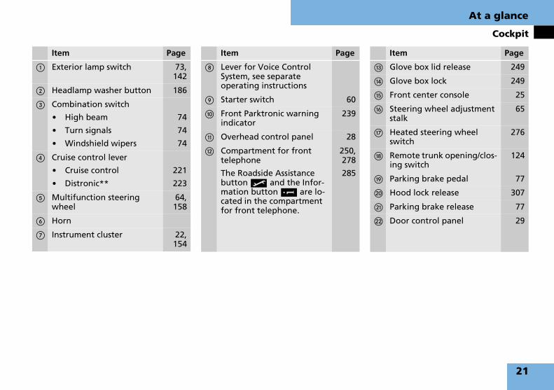
Item Page
1 Exterior lamp switch 73,142
2 Headlamp washer button 186
3 Combination switch
� High beam
� Turn signals
� Windshield wipers
74
74
74
4 Cruise control lever
� Cruise control
� Distronic**
221
223
5 Multifunction steering wheel
64,158
6 Horn
7 Instrument cluster 22,154
Item Page
8 Lever for Voice Control System, see separate operating instructions
9 Starter switch 60
a Front Parktronic warning indicator
239
b Overhead control panel 28
c Compartment for front telephone
The Roadside Assistance button • and the Infor-mation button ¡ are lo-cated in the compartment for front telephone.
250,278
285
Item Page
d Glove box lid release 249
e Glove box lock 249
f Front center console 25
g Steering wheel adjustment stalk
65
h Heated steering wheel switch
276
j Remote trunk opening/clos-ing switch
124
k Parking brake pedal 77
l Hood lock release 307
m Parking brake release 77
n Door control panel 29
21

At a glance
Instrument cluster
Instrument cluster
22

At a glance
Instrument cluster
Item Page
1 Coolant temperature gauge
155
2 Fuel gauge with fuel reserve warning lamp
355
3 L Left turn signal indi-cator lamp
74
4 Speedometer 156
5 v ABS/ESP® warning lamp
103,105,354
6 l Distance warning lamp1
1 Vehicles without Distronic**: Warning lamp without function. It illuminates when the igni-tion is on. It should go out when the engine is running.
223,356
7 K Right turn signal in-dicator lamp
74
8 Tachometer 155
9 - Antilock Brake Sys-tem (ABS) indicator lamp
103,356
Item Page
a A High beam head-lamp indicator lamp
145
b J Reset button 154
c < Seat belt telltale 92,357
d Digital clock (see separate COMAND and Rear-Cabin Audiovisual Sys-tem operating instructions)
e Gear selector lever position and program mode
180
f Main odometer 157
g Trip odometer 155
h Multifunction display 157
j Outside temperature indi-cator
155
Item Page
k H Tire inflation pres-sure warning lamp
359
l Knob for instrument cluster illumination
154
m ? Engine malfunction indicator lamp,USA only
361
± Engine malfunction indicator lamp,Canada only
361
n ; Brake warning lamp, USA only
360
3 Brake warning lamp, Canada only
360
o 1 Supplemental Restraint System (SRS) indicator lamp
82,359
23

At a glance
Multifunction steering wheel
Multifunction steering wheel Item Page
1 Multifunction display 157
Operating control system 158
2 Selecting the submenu or setting the volume:
Press button
æ up/to increase
ç down/to decrease
3 Telephone:
Press button
s to take a callto dial a callto redial
t to end a callto reject an incoming call
Item Page
4 Menu systems:
Press button
è for next menu
ÿ for previous menu
5 Moving within a menu:
Press button
j for next display
k for previous display
24
At a glance
Front center console
Front center console
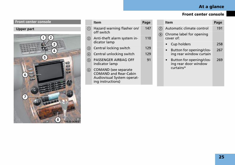
Upper part
Item Page
1 Hazard warning flasher on/off switch
147
2 Anti-theft alarm system in-dicator lamp
110
3 Central locking switch 129
4 Central unlocking switch 129
5 PASSENGER AIRBAG OFF indicator lamp
91
6 COMAND (see separate COMAND and Rear-Cabin Audiovisual System operat-ing instructions)
Item Page
7 Automatic climate control 191
8 Chrome label for opening cover of:
� Cup holders 258
� Button for opening/clos-ing rear window curtain
267
� Button for opening/clos-ing rear door window curtains*
269
25

At a glance
Front center console
Maybach 57 and Maybach 62 without partition*
i Depending on equipment, the arrange-ment of switches and buttons may vary.
Lower part Item Page
1 KEYLESS-GO** start/stop button
61,71
2 Gear selector lever for au-tomatic transmission
70
3 Parking Assist System (PAS) parallel parking button
244
4 Button for retracting/ex-tending rear seat head re-straints
134
5 Parking assist (Parktronic system) deactivation but-ton
240
6 Two-way intercom* on/off button (only Maybach 62)
274
Item Page
7 Chrome label for opening cover of:
� Ashtray 260
� Lighter 262
� Storage compartment* 263
8 Thumbwheel for setting distance in Distronic**
230
9 Distance warning func-tion** on/off button
230
a Level control button 236
b Airmatic DC button 233
c Electronic Stability Program (ESP®) control switch
106
d Program mode selector switch for automatic trans-mission
184
26

At a glance
Front center console
Maybach 62 with partition*
i Depending on equipment, the arrange-ment of switches and buttons may vary.
Item Page
1 KEYLESS-GO** start/stop button
61,71
2 Gear selector lever for au-tomatic transmission
70
3 Parking Assist System (PAS) parallel parking button
244
4 Button for retracting/ex-tending rear seat head re-straints
134
5 Parking assist (Parktronic system) deactivation but-ton
240
6 Two-way intercom on/off button
274
7 Button for opening/closing partition* curtain
273
Item Page
8 Partition* opening/closing button
271
9 Chrome label for opening cover of:
� Ashtray 260
� Lighter 262
� Storage compartment* 263
a Thumbwheel for setting distance in Distronic**
230
b Distance warning func-tion** on/off button
230
c Level control button 236
d Airmatic DC button 233
e Electronic Stability Program (ESP®) control switch
106
f Program mode selector switch for automatic trans-mission
184
27

At a glance
Overhead control panel
d
Overhead control panel Item Page
1 Left front reading lamp on/off
148
2 Rear interior lighting on/off 148
3 Interior lighting control 148
4 Right front reading lamp on/off
148
5 Front interior lighting on/off
148
6 Tow-away alarm button 112
7 Rear view mirror 66,186
8 Garage door opener 289
9 Auto-dimming function on/off
186
Item Page
a Hands-free microphone for:
� Telephone 277
� Tele Aid (emergency call system)
� Voice Control System, see separate operating instructions
281
b Tele Aid (emergency call system) button
281
c Switch for opening/closing power tilt/sliding sunroof (Maybach 57)
212
Switch for opening/closing power tilt/sliding sunroof (Maybach 62)
214
Switch for operating electrotransparent roof* screen
218
28
At a glance
Driver’s door control panel
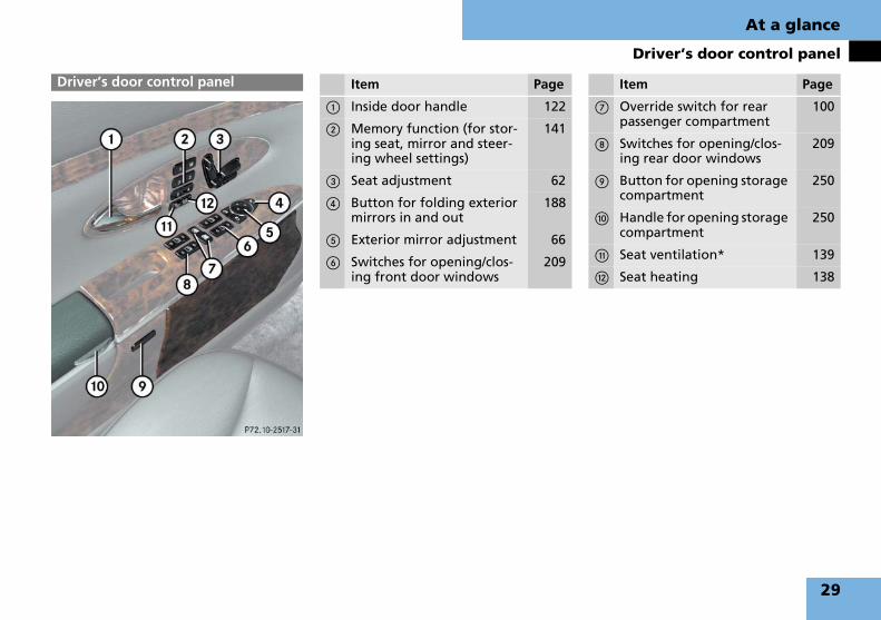
Driver’s door control panel Item Page
1 Inside door handle 122
2 Memory function (for stor-ing seat, mirror and steer-ing wheel settings)
141
3 Seat adjustment 62
4 Button for folding exterior mirrors in and out
188
5 Exterior mirror adjustment 66
6 Switches for opening/clos-ing front door windows
209
Item Page
7 Override switch for rear passenger compartment
100
8 Switches for opening/clos-ing rear door windows
209
9 Button for opening storage compartment
250
a Handle for opening storage compartment
250
b Seat ventilation* 139
c Seat heating 138
29

At a glance
Rear passenger compartment
Rear passenger compartment
Maybach 57 (vehicles without rear center seat*)
30

At a glance
Rear passenger compartment
Item Page
1 Vanity mirror, left 248
2 Speedometer 156
3 Clock (see separate COMAND and Rear-Cabin Audiovisual System operat-ing instructions)
156
4 Outside temperature gauge
155
Item Page
5 Vanity mirror, right 248
6 Video monitor, right (see separate COMAND and Rear-Cabin Audiovisual Sys-tem operating instructions)
7 Button for opening multifunction compart-ment*, right
253
8 Automatic climate control panel
253
Item Page
9 Button for opening storage compartment/drawer
252
a Button for opening multifunction compart-ment*, left
253
b Video monitor, left (see separate COMAND and Rear-Cabin Audiovisual Sys-tem operating instructions)
31

At a glance
Rear passenger compartment
Maybach 57 (vehicles with rear center seat*)
32

At a glance
Rear passenger compartment
Item Page
1 Vanity mirror, left 248
2 Speedometer 156
3 Clock (see separate COMAND and Rear-Cabin Audiovisual System operat-ing instructions)
156
4 Outside temperature gauge
155
Item Page
5 Vanity mirror, right 248
6 Video monitor, right (see separate COMAND and Rear-Cabin Audiovisual Sys-tem operating instructions)
7 Button for opening multifunction compart-ment*, right
253
8 Automatic climate control panel
206
Item Page
9 Vehicles with rear center seat*: control panel for rear functions in rear center console
47
a Button for opening multifunction compart-ment*, left
253
b Video monitor, left (sepa-rate COMAND and Rear-Cabin Audiovisual System operating instructions)
33

At a glance
Rear passenger compartment
Maybach 62 without partition*
34

At a glance
Rear passenger compartment
Item Page
1 Vanity mirror, left 248
2 Speedometer 156
3 Clock (see separate COMAND and Rear-Cabin Audiovisual System operat-ing instructions)
156
4 Outside temperature gauge
155
5 Vanity mirror, right 248
Item Page
6 Video monitor, right (see separate COMAND and Rear-Cabin Audiovisual Sys-tem operating instructions)
7 Button for opening upper storage compartment
253
8 Button for opening multifunction compart-ment*, right
253
9 Automatic climate control panel
206
Item Page
a Button for opening storage compartment/drawer
Vehicles with rear center seat*: control panel for rear functions in the storage compartment/drawer
252
49,52
b Button for opening multifunction compart-ment*, left
253
c Video monitor, left (see separate COMAND and Rear-Cabin Audiovisual Sys-tem operating instructions)
35

At a glance
Rear passenger compartment
Maybach 62 with partition*
36

At a glance
Rear passenger compartment
Item Page
1 Vanity mirror, left 248
2 Speedometer 156
3 Clock (see separate COMAND and Rear-Cabin Audiovisual System operat-ing instructions)
156
4 Outside temperature gauge
155
5 Vanity mirror, right 248
Item Page
6 Video monitor, right (see separate COMAND and Rear-Cabin Audiovisual Sys-tem operating instructions)
7 Button for opening upper storage compartment
253
8 Storage pocket, right 254
9 Automatic climate control panel
206
Item Page
a Button for opening storage compartment/drawer
Vehicles with rear center seat*: control panel for rear functions in the storage compartment/drawer
252
49,52
b Storage pocket, left 254
c Video monitor, left (see separate COMAND and Rear-Cabin Audiovisual Sys-tem operating instructions)
37

At a glance
Rear seats
Rear seats
Maybach 57 (vehicles without rear center seat*)
38
At a glance
Rear seats
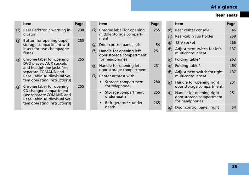
Item Page
1 Rear Parktronic warning in-dicator
238
2 Button for opening upper storage compartment with insert for two champagne flutes
255
3 Chrome label for opening DVD player, AUX sockets and headphone jacks (see separate COMAND and Rear-Cabin Audiovisual Sys-tem operating instructions)
255
4 Chrome label for opening CD changer compartment (see separate COMAND and Rear-Cabin Audiovisual Sys-tem operating instructions)
255
Item Page
5 Chrome label for opening middle storage compart-ment
255
6 Door control panel, left 54
7 Handle for opening left door storage compartment for headphones
251
8 Handle for opening left door storage compartment
251
9 Center armrest with
� Storage compartment for telephone
280
� Storage compartment underneath
255
� Refrigerator** under-neath
265
Item Page
a Rear center console 46
b Rear-cabin cup holder 258
c 12-V socket 266
d Adjustment switch for left multicontour seat
137
e Folding table* 263
f Folding table* 263
g Adjustment switch for right multicontour seat
137
h Handle for opening right door storage compartment
251
j Handle for opening right door storage compartment for headphones
251
k Door control panel, right 54
39

At a glance
Rear seats
Maybach 57 (vehicles with rear center seat*)
40

At a glance
Rear seats
Item Page
1 Rear Parktronic warning in-dicator
238
2 Rear center backrest
� DVD player compart-ment, CD changer com-partment, AUX sockets and headphone jacks lo-cated behind backrest (see separate COMAND and Rear-Cabin Audiovi-sual System operating instructions)
256
� Storage compartment between the rear outer seats located behind backrest
256
� Center armrest with storage compartment for telephone (backrest folded down)
280
Item Page
� Vehicles with rear cen-ter seat*: Center arm-rest with storage compartment (backrest folded down) for
� telephone and
� control panel for rear functions
280
47
3 Door control panel, left 54
4 Handle for opening left door storage compartment for headphones
251
5 Handle for opening left door storage compartment for ashtray
251
6 Cup holder 259
Item Page
7 Adjustment switch for left multicontour seat
137
8 12-V socket 266
9 Switch for rear center seat head restraints
135
a Cup holder 259
b Adjustment switch for right multicontour seat
137
c Handle for opening right door storage compartment for ashtray
251
d Handle for opening right door storage compartment for headphones
251
e Door control panel, right 54
41

At a glance
Rear seats
Maybach 62 (vehicles without rear center seat*)
42

At a glance
Rear seats
Item Page
1 Rear Parktronic warning in-dicator
238
2 Button for opening upper storage compartment with insert for two champagne flutes
255
3 Chrome label for opening DVD player, AUX sockets and headphone jacks (see separate COMAND and Rear-Cabin Audiovisual Sys-tem operating instructions)
255
4 Chrome label for opening CD changer compartment (see separate COMAND and Rear-Cabin Audiovisual Sys-tem operating instructions)
255
5 Chrome label for opening middle storage compart-ment
255
Item Page
6 Door control panel, left 55
7 Handle for opening left door storage compartment for headphones
251
8 Handle for opening left door storage compartment
251
9 Button for opening storage compartment
251
a Storage compartment 251
b Adjustment switch for left multicontour seat
137
c Center armrest with
� Storage compartment for telephone
280
� Storage compartment underneath
255
� Refrigerator** under-neath
265
Item Page
d Rear center console 46
e Rear-cabin cup holder 258
f 12-V socket 266
g Folding table 264
h Folding table 264
j Adjustment switch for right multicontour seat
137
k Handle for opening right door storage compartment for headphones
251
l Handle for opening right door storage compartment
251
m Button for opening storage compartment
251
n Storage compartment 251
o Door control panel, right 55
43

At a glance
Rear seats
Maybach 62 (vehicles with rear center seat*)
44

At a glance
Rear seats
Item Page
1 Rear Parktronic warning in-dicator
238
2 Rear center backrest
� DVD player compart-ment, CD changer com-partment, AUX sockets and headphone jacks lo-cated behind backrest (see separate COMAND and Rear-Cabin Audiovi-sual System operating instructions)
256
� Storage compartment between the rear outer seats located behind backrest
256
� Center armrest with storage compartment for telephone (backrest folded down)
280
Item Page
� Vehicles with rear cen-ter seat*: Center arm-rest with storage compartment (backrest folded down) for
� telephone and
� control panel for rear functions
280
49,52
3 Door control panel, left 55
4 Handle for opening left door storage compartment for headphones
251
5 Handle for opening left door storage compartment for ashtray
251
6 Adjustment switch for left multicontour seat
137
7 Button for opening storage compartment
251
Item Page
8 Storage compartment 251
9 Cup holder 259
a 12-V socket 266
b Switch for rear center seat head restraints
135
c Cup holder 259
d Adjustment switch for right multicontour seat
137
e Handle for opening right door storage compartment for headphones
251
f Handle for opening right door storage compartment for ashtray
251
g Button for opening storage compartment
251
h Storage compartment 251
j Door control panel, right 55
45

At a glance
Rear center console
Example with rear door window curtains*
i Depending on equipment, the arrange-ment of switches and buttons may vary.
Rear center console
Maybach 57 (vehicles without rear center seat*)
Item Page
1 Left reading lamp on/off 149
2 Tele Aid (emergency call system) button
281
3 Right reading lamp on/off 149
4 Ambient lighting on/off 149
Rear interior lamps on/off 149
5 Thumbwheel for dimming ambient lighting
149
6 Cover of compartment with:
� Ashtray 260
� Lighter 262
� Storage compartment* 263
Item Page
7 Button for opening/closing rear right side door win-dow curtain*
269
8 Button for opening/closing rear window curtain (only if equipped with rear door window curtains*)
267
9 Button for opening/closing rear left side door window curtain*
269
a Rear interior lamps on/off 149
Button for opening/closing rear window curtain (only if not equipped with rear door window curtains*)
267
b Central unlocking switch 129
c Central locking switch 129
46

At a glance
Rear center console
Control panel for rear functions* in rear center console
i Depending on equipment, the arrange-ment of switches and buttons may vary.
Control panel for rear window curtains* in rear armrest compartment
Maybach 57 (vehicles with rear center seat*)
Item Page
1 Left reading lamp on/off 149
2 Tele Aid (emergency call system) button
281
3 Right reading lamp on/off 149
4 Ambient lighting on/off 149
Rear interior lamps on/off 149
5 Thumbwheel for dimming ambient lighting
149
6 Rear interior lamps on/off 149
Button for opening/closing rear window curtain (only if not equipped with rear door window curtains*)
267
7 Central locking switch 129
8 Central unlocking switch 129
Item Page
1 Button for opening/closing rear right side door win-dow curtain*
269
2 Button for opening/closing rear window curtain (only if equipped with rear door window curtains*)
267
3 Button for opening/closing rear left side door window curtain*
269
47
At a glance
Rear center console
i Depending on equipment, the arrange-ment of switches and buttons may vary.
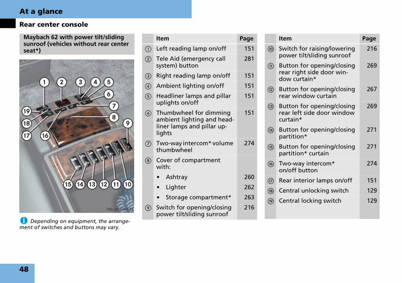
Maybach 62 with power tilt/sliding sunroof (vehicles without rear center seat*)
Item Page
1 Left reading lamp on/off 151
2 Tele Aid (emergency call system) button
281
3 Right reading lamp on/off 151
4 Ambient lighting on/off 151
5 Headliner lamps and pillar uplights on/off
151
6 Thumbwheel for dimming ambient lighting and head-liner lamps and pillar up-lights
151
7 Two-way intercom* volume thumbwheel
274
8 Cover of compartment with:
� Ashtray 260
� Lighter 262
� Storage compartment* 263
9 Switch for opening/closing power tilt/sliding sunroof
216
Item Page
a Switch for raising/lowering power tilt/sliding sunroof
216
b Button for opening/closing rear right side door win-dow curtain*
269
c Button for opening/closing rear window curtain
267
d Button for opening/closing rear left side door window curtain*
269
e Button for opening/closing partition*
271
f Button for opening/closing partition* curtain
271
g Two-way intercom* on/off button
274
h Rear interior lamps on/off 151
j Central unlocking switch 129
k Central locking switch 129
48

At a glance
Rear center console
Control panel for rear functions* in stor-age compartment/drawer
i Depending on equipment, the arrange-ment of switches and buttons may vary.
Maybach 62 with power tilt/sliding sunroof (vehicles with rear center seat*)
Item Page
1 Tele Aid (emergency call system) button
281
2 Right reading lamp on/off 151
3 Ambient lighting on/off 151
4 Headliner lamps and pillar uplights on/off
151
5 Thumbwheel for dimming ambient lighting and head-liner lamps and pillar up-lights
151
6 Two-way intercom* volume thumbwheel
274
Item Page
7 Two-way intercom* on/off button
274
8 Rear interior lamps on/off 151
9 Central locking switch 129
a Central unlocking switch 129
b Left reading lamp on/off 151
c Remote control (see sepa-rate COMAND and Rear-Cabin Audiovisual System operating instructions)
49

At a glance
Rear center console
Control panel for rear functions* in rear armrest compartment
i Depending on equipment, the arrange-ment of switches and buttons may vary.
Item Page
1 Switch for opening/closing power tilt/sliding sunroof
216
2 Switch for raising/lowering power tilt/sliding sunroof
216
3 Button for opening/closing rear right side door win-dow curtain*
269
4 Button for opening/closing rear window curtain
267
Item Page
5 Button for opening/closing rear left side door window curtain*
269
6 Button for opening/closing partition*
271
7 Button for opening/closing partition* curtain
271
50

At a glance
Rear center console
i Depending on equipment, the arrange-ment of switches and buttons may vary.
Maybach 62 with electrotransparent roof*(vehicles without rear center seat*)
Item Page
1 Left reading lamp on/off 151
2 Tele Aid (emergency call system) button
281
3 Right reading lamp on/off 151
4 Ambient lighting on/off 151
5 Roof lighting on/off 151
6 Thumbwheel for dimming ambient lighting or roof lighting
151
7 Two-way intercom* volume thumbwheel
274
8 Cover of compartment with:
� Ashtray 260
� Lighter 262
� Storage compartment* 263
9 Switch for opening/closing electrotransparent roof* screen
219
Item Page
a Switch for making elec-trotransparent roof* opaque/transparent
219
b Button for opening/closing rear right side door win-dow curtain*
269
c Button for opening/closing rear window curtain
267
d Button for opening/closing rear left side door window curtain*
269
e Button for opening/closing partition*
271
f Button for opening/closing partition* curtain
271
g Two-way intercom* on/off button
274
h Rear interior lamps on/off 151
j Central unlocking switch 129
k Central locking switch 129
51
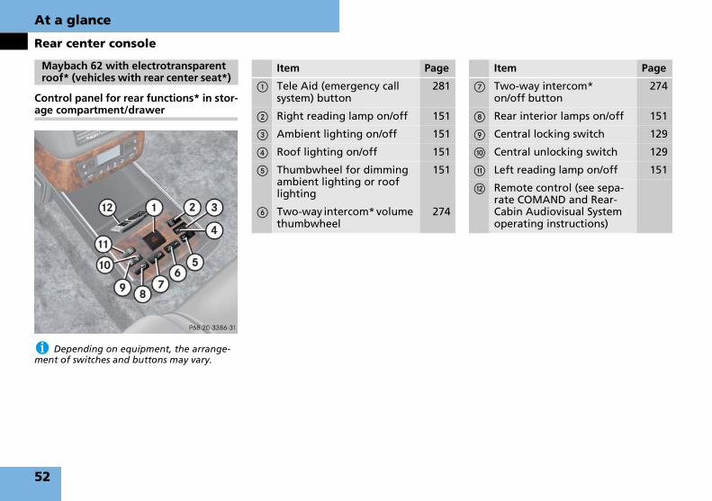
At a glance
Rear center console
Control panel for rear functions* in stor-age compartment/drawer
i Depending on equipment, the arrange-ment of switches and buttons may vary.
Maybach 62 with electrotransparent roof* (vehicles with rear center seat*)
Item Page
1 Tele Aid (emergency call system) button
281
2 Right reading lamp on/off 151
3 Ambient lighting on/off 151
4 Roof lighting on/off 151
5 Thumbwheel for dimming ambient lighting or roof lighting
151
6 Two-way intercom* volume thumbwheel
274
Item Page
7 Two-way intercom* on/off button
274
8 Rear interior lamps on/off 151
9 Central locking switch 129
a Central unlocking switch 129
b Left reading lamp on/off 151
c Remote control (see sepa-rate COMAND and Rear-Cabin Audiovisual System operating instructions)
52

At a glance
Rear center console
Control panel for rear functions* in rear armrest compartment
i Depending on equipment, the arrange-ment of switches and buttons may vary.
Item Page
1 Switch for opening/closing electrotransparent roof* screen
219
2 Switch for making elec-trotransparent roof* opaque/transparent
219
3 Button for opening/closing rear right side door win-dow curtain*
269
Item Page
4 Button for opening/closing rear window curtain
267
5 Button for opening/closing rear left side door window curtain*
269
6 Button for opening/closing partition*
271
7 Button for opening/closing partition* curtain
271
53

At a glance
Rear door control panel
Rear door control panel
Maybach 57
Item Page
1 Selection switch for right front passenger seat adjust-ment1
1 These switches are located on the right rear pas-senger side only.
135
2 Selection switch for right rear seat adjustment1
135
3 Memory button for storing rear seat positions
141
4 Inside door handle 122
5 Seat ventilation* 139
6 Seat heating 138
7 Seat adjustment 132
8 Switches for opening/clos-ing rear door window
209
54

At a glance
Rear door control panel
Maybach 62 Item Page
1 Selection switch for right front passenger seat adjust-ment1
1 These switches are located on the right rear pas-senger side only.
135
2 Selection switch for right rear seat adjustment1
135
3 Memory button for storing rear seat positions
141
4 Inside door handle 122
5 Switch for moving seat to fully reclined position
133
6 Seat ventilation* 139
7 Seat heating 138
8 Switch for moving seat to upright position
133
9 Seat adjustment 133
a Switches for opening/clos-ing rear door window
209
55

56

Getting started
Unlocking
Adjusting
Driving
Parking and locking
57

Getting started
Unlocking
The “Getting started” section provides an overview of the vehicle’s most basic functions. First-time Maybach owners should pay special attention to the infor-mation given here.
If you are already familiar with the basic functions described here, the “Controls in detail” section will provide you with further information. The corresponding page references are located at the end of each segment.
SmartKey with remote control
1  Panic button (� page 102)2 Š Opening button for trunk3 Œ Unlock button4 ‹ Lock button
� Press unlock button Œ on the SmartKey.
All turn signal lamps flash once. The vehicle unlocks. The locking knobs in the doors move up. The anti-theft alarm system is disarmed.
� Get in the vehicle and insert the SmartKey in the starter switch.
For more information, see “SmartKey” (� page 114).
Unlocking Unlocking with the SmartKey
Warning! G
When leaving the vehicle, always remove the SmartKey from the starter switch, take it with you, and lock the vehicle. Do not leave children unattended in the vehicle, or with access to an unlocked vehicle. A child’s unsupervised access to a vehicle could result in an accident and/or serious personal injury.
58

Getting started
Unlocking
With the KEYLESS-GO function, you can lock and unlock the vehicle without us-ing the remote control buttons on the SmartKey and start the engine without inserting the SmartKey in the starter switch.
i To unlock the vehicle, the SmartKey with KEYLESS-GO must be outside the vehicle, no further than approximately 3 feet (1 meter) away from the door.
� Grasp an outside door handle.
All turn signal lamps flash once. The vehicle unlocks. The locking knobs in the doors move up. The anti-theft alarm system is disarmed.
i If the vehicle has been parked for more than 72 hours, you must pull an outside door handle in order to activate the KEYLESS-GO function.
� Get in the vehicle.
For more information, see “ SmartKey with KEYLESS-GO**” (� page 117).
Unlocking with KEYLESS-GO**
Warning! G
When leaving the vehicle, always take the SmartKey with KEYLESS-GO with you, and lock the vehicle. Do not leave children un-attended in the vehicle, or with access to an unlocked vehicle. A child’s unsupervised access to a vehicle could result in an acci-dent and/or serious personal injury.
59

Getting started
Unlocking
SmartKey
Starter switch
0 For removing SmartKey
1 Power supply for some electrical con-sumers, such as seat adjustment
2 Ignition (power supply for all electri-cal consumers) and driving position. All lamps (except high beam head-lamp indicator lamp and turn signal indicator lamps unless activated) in the instrument come on. If a lamp in the instrument cluster fails to come on when the ignition is switched on, have it checked and replaced if neces-sary. If a lamp in the instrument clus-ter remains on after starting the engine or comes on while driving, re-fer to “Lamps in instrument cluster” (� page 354).
3 Starting position
i When you switch on the ignition, the in-dicator and warning lamps (except high beam headlamp indicator lamp and turn signal indi-cator lamps unless activated) in the instru-ment cluster come on. The indicator and warning lamps (except high beam headlamp indicator lamp and turn signal indicator lamps if activated) should go out when the engine is running. This indicates that the respective sys-tems are operational.
i The SmartKey can only be removed from the starter switch with the gear selector lever in position P.
! If the SmartKey can still not be turned, the battery may not be sufficiently charged.
� Check the starter battery and charge it if necessary (� page 417).
� Get a jump start (� page 421).
To prevent accelerated battery discharge or a completely discharged battery, always re-move the SmartKey from the starter switch.
For information on starting the engine using the SmartKey, see “Starting with the SmartKey” (� page 71).
SmartKey with KEYLESS-GO**
If the SmartKey with KEYLESS-GO is in-side the vehicle, pressing the KEYLESS-GO start/stop button on the gear selector lever corresponds to turn-ing the SmartKey to the various starter switch positions.
If you firmly depress the brake pedal dur-ing pressing KEYLESS-GO start/stop but-ton, the engine starts automatically.
i The function of the SmartKey overrules the KEYLESS-GO function.
Starter switch positions
Warning! G
When leaving the vehicle, always remove the SmartKey or SmartKey with KEYLESS-GO** from the starter switch, take it with you, and lock the vehicle. Do not leave children unattended in the vehi-cle, or with access to an unlocked vehicle. A child’s unsupervised access to a vehicle could result in an accident and/or serious personal injury.
60

Getting started
Unlocking
KEYLESS-GO start/stop button
1 USA only2 Canada only
The SmartKey with KEYLESS-GO must be located in the vehicle.
� Make sure the gear selector lever is set to P.
� Do not depress the brake pedal.
Position 0
Before you press the KEYLESS-GO start/stop button, the vehicle’s on-board elec-tronics have status 0 (as with SmartKey removed).
Position 1
� Press KEYLESS-GO start/stop button once.
This supplies power for some electri-cal consumers, such as seat adjust-ment.
i If you now press the KEYLESS-GO start/stop button
� once again, the ignition (position 2) is switched on
� twice, the power supply is again switched off
Ignition (or position 2)
� Press KEYLESS-GO start/stop button twice.
This supplies power for all electrical consumers.
All lamps in the instrument cluster (except high beam headlamp indica-tor lamp and turn signal indicator lamps unless activated) come on. If a lamp in the instrument cluster fails to come on when the ignition is switched on, have it checked and replaced if necessary. If a lamp in the instrument cluster remains on after starting the engine or comes on while driving, refer to “Lamps in instru-ment cluster” (� page 354).
i If you now press the KEYLESS-GO start/stop button once, the power supply is again switched off.
i When you switch on the ignition, the in-dicator and warning lamps (except high beam headlamp indicator lamp and turn signal indi-cator lamps unless activated) in the instru-ment cluster come on. The indicator and warning lamps (except high beam headlamp indicator lamp and turn signal indicator lamps if activated) should go out when the engine is running. This indicates that the respective sys-tems are operational.
For information on starting the engine using the KEYLESS-GO start/stop button, see “Starting with KEYLESS-GO**” (� page 71).
61

Getting started
Adjusting
Adjusting
Warning! G
All seat, head restraint, steering wheel, and rear view mirror adjustments, as well as fastening of seat belts, must be done be-fore the vehicle is put into motion.
Seats
Warning! G
Do not adjust the driver’s seat while driv-ing. Adjusting the seat while driving could cause the driver to lose control of the vehi-cle.
Never ride in a moving vehicle with the seat back in an excessively reclined posi-tion as this can be dangerous. You could slide under the seat belt in a collision. If you slide under it, the seat belt would ap-ply force at the abdomen or neck. That could cause serious or fatal injuries. The seat backrest and seat belts provide the best restraint when the wearer is in a near-ly upright position and seat belts are prop-erly positioned on the body.
Only the reclining seat (in Maybach 62 rear cabin) can be used in a reclined position with seat belts properly fastened while the vehicle is in motion. The reclining seat in
the Maybach 62 rear cabin includes a seat belt system and kinematic electronic con-trols that are designed to maintain proper support and restraint-system effectiveness in all seat settings in the event of a collision or similar situation.
Warning! G
Your seat must be adjusted so that you can correctly fasten your seat belt (� page 68).
Observe the following points:
� Adjust the backrest until your arms are slightly angled when holding the steer-ing wheel.
� Adjust the seat to a comfortable seat-ing position that still allows you to reach the accelerator/brake pedal safe-ly. The position should be as far to the rear as possible, consistent with ability to properly operate controls.
� Adjust the head restraint so that it is as close to the head as possible and the center of the head restraint supports the back of the head at eye level.
� Never place hands under the seat or near any moving parts while a seat is being adjusted.
Failure to do so could result in an accident and/or serious personal injury.
Warning! G
When leaving the vehicle, always remove the SmartKey or SmartKey with KEYLESS-GO** from the starter switch, take it with you, and lock the vehicle.
Even with the SmartKey or the SmartKey with KEYLESS-GO** removed from the starter switch or the SmartKey with KEYLESS-GO** removed from the vehicle, the power seats can be operated when the respective door is open. Therefore, do not leave children unattended in the vehicle, or with access to an unlocked vehicle. A child’s unsupervised access to a vehicle could result in an accident and/or serious personal injury.
62

Getting started
Adjusting
Seat adjustment
The seat adjustment switches are located on each door.
1 Seat fore and aft adjustment2 Seat height3 Seat cushion tilt4 Seat backrest tilt5 Seat cushion depth6 Head restraint height
� Switch on the ignition (� page 60).
or
� Open the respective door.
i The memory function (� page 140) lets you store settings for the seat positions to-gether with the settings for the steering wheel and rear view mirrors.
! When moving the seat, make sure there are no items in the footwell or behind the seats. Otherwise you could damage the seats.
Seat fore and aft adjustment
� Press switch forward or backward in direction of arrow 1.
i Depending on the set height of the head restraint, the seat fore and aft position is au-tomatically pre-set.
Seat height
� Press switch up or down in direction of arrow 2.
Seat cushion tilt
� Press switch up or down in direction of arrow 3 until your upper legs are lightly supported.
Seat backrest tilt
� Press switch forward or backward in direction of arrow 4.
Warning! G
According to accident statistics, children are safer when properly restrained in the rear seating positions than in the front seating position. Thus, we strongly recom-mend that children be placed in the rear seats whenever possible. Regardless of seating position, children 12 years old and under must be seated and properly se-cured in an appropriate infant or toddler restraint, or booster seat recommended for the size and weight of the child. For ad-ditional information, see “Children in the vehicle” (� page 95).
A child’s risk of serious or fatal injuries is significantly increased if the child re-straints are not properly secured in the ve-hicle and the child is not properly secured in the child restraint.
��
63

Getting started
Adjusting
�
Seat cushion depth
� Press switch forward or backward in direction of arrow 5 until your legs are supported comfortably.
Head restraint height
� Press switch up or down in direction of arrow 6.
Head restraint tilt
Manually adjust the angle of the head restraint.
� Push or pull on the lower edge of the head restraint cushion.
i Adjust the head restraint in such a way that it is as close to the head as possible.
For more information, see “Seats” (� page 131).
Warning! G
For your protection, drive only with prop-erly positioned head restraints.
Adjust the head restraint so that it is as close to the head as possible and the cen-ter of the head restraint supports the back of the head at eye level. This will reduce the potential for injury to the head and neck in the event of an accident or similar situation.
Do not drive the vehicle without the seat head restraints. Head restraints are intend-ed to help reduce injuries during an acci-dent.
�Steering wheel
Warning! G
Do not adjust the steering wheel while driving. Adjusting the steering wheel while driving could cause the driver to lose control of the vehicle.
When leaving the vehicle, always remove the SmartKey or SmartKey with KEYLESS-GO** from the starter switch, take it with you, and lock the vehicle.
Even with the SmartKey or SmartKey with KEYLESS-GO** removed from the starter switch or the SmartKey with KEYLESS-GO** removed from the vehicle, the steering wheel adjustment feature can be operated when the driver’s door is open. Therefore, do not leave children un-attended in the vehicle, or with access to an unlocked vehicle. A child’s unsupervised access to a vehicle could result in an acci-dent and/or serious personal injury.
64

Getting started
Adjusting
Steering wheel adjustment
1 Adjusting steering column, in or out2 Adjusting steering column, up or
down
� Switch on the ignition (� page 60).
or
� Open the driver’s door.
i The memory function (� page 140) lets you store settings for the steering wheel to-gether with settings for the rear view mirrors and seat positions.
Adjusting steering column in or out
� Move stalk forward or backward in direction of arrow 1 until a comfort-able steering wheel position is reached with your arms slightly bent at the elbow.
Adjusting steering column up or down
� Move the stalk up or down in direc-tion of arrow 2.
Make sure your legs can move freely and that all of the displays (including mal-function and indicator lamps) on the in-strument cluster are clearly visible.
For more information, see “Heated steering wheel” (� page 276).
Easy-entry/exit feature
This feature allows for easier entry into and exit from the vehicle. When entering and exiting the vehicle, the steering wheel is in its uppermost position.
The easy-entry/exit feature can be acti-vated or deactivated in the CONVENIENCE submenu of the control system (� page 177).
Warning! G
You must make sure no one can become trapped or injured by the moving steering wheel when the easy-entry/exit feature is activated.
To stop steering wheel movement, do one of the following:
� Move steering wheel adjustment stalk (� page 64).
� Press seat adjustment switch (� page 63).
� Press one of the memory position but-tons or the memory button M (� page 140).
Do not leave children unattended in the vehicle, or with access to an unlocked vehi-cle. Children could open the driver’s door and unintentionally activate the easy-en-try/exit feature, which could result in an accident and/or serious personal injury.
65

Getting started
Adjusting
With the easy-entry/exit feature activat-ed, the steering wheel will return to its last set position when you
� close the driver’s door with the igni-tion switched on
or
� insert the SmartKey into the starter switch or press the KEYLESS-GO** start/stop button (� page 61) once with the driver’s door closed.
i The last set steering wheel position is stored when
� the ignition is switched off
� the position is stored in memory (� page 140)
With the easy-entry/exit feature activat-ed, the steering wheel tilts upwards when you:
� remove the SmartKey from the start-er switch,
or
� open the driver’s door with the SmartKey in starter switch position 0 or 1 or the KEYLESS-GO** start/stop button in position 1 (� page 60).
i If the current position for the steering wheel is in the uppermost tilt position, the steering wheel will no longer be able to move upward when the easy-entry/exit feature is ac-tivated.
The adjustment procedure is briefly interrupt-ed when the engine is started.
Adjust the interior and exterior rear view mirrors before driving so that you have a good view of the road and traffic condi-tions.
! Electrolyte drops coming into contact with the vehicle paint finish can only be com-pletely removed while in their liquid state and by applying plenty of water.
i The memory function (� page 140) lets you save the rear view mirror settings togeth-er with the settings for the steering wheel and seat positions.
Warning! G
Let the system complete the adjustment procedure before setting the vehicle in motion. All steering wheel adjustment must be completed before setting the ve-hicle in motion. Driving off with the steer-ing wheel still adjusting could cause the driver to lose control of the vehicle.
Mirrors
Warning! G
In case of an accident, liquid electrolyte may escape the mirror housing if the mir-ror glass breaks.
Electrolyte has an irritating effect. Do not allow the liquid to come into contact with eyes, skin, clothing, or respiratory system. In case it does, immediately flush affected area with water, and seek medical help if necessary.
66

Getting started
Adjusting
Interior rear view mirror
� Manually adjust the interior rear view mirror.
For more information, see “Rear view mirrors” (� page 186).
Exterior rear view mirrors
1 Driver’s side exterior rear view mirror button
2 Passenger-side exterior rear view mir-ror button
3 Adjustment button
� Switch on the ignition (� page 60).
� Press button 1 for the driver’s side exterior rear view mirror or button 2 for the passenger-side exterior rear view mirror.
� Push adjustment button 3 up, down, left, or right according to the desired setting.
! For information on how to reposition the exterior mirror housing when it was forcibly pushed forward (hit from the rear) or forcibly pushed rearward (hit from the front), see “Power folding exterior rear view mirrors” (� page 188).
i At low ambient temperatures, the exteri-or rear view mirrors will be heated automati-cally.
For more information, see “Rear view mirrors” (� page 186).Warning! G
With the exterior rear view mirrors folded in when driving the vehicle, you cannot observe surrounding traffic conditions and which could result in an accident. Before driving the vehicle, make sure the exterior rear view mirrors are folded out.
Warning! G
Exercise care when using the passenger-side exterior rear view mirror. The mirror surface is convex (outwardly curved sur-face for a wider field of view). Objects in mirror are closer than they appear. Check your interior rear view mirror or glance over your shoulder before changing lanes.
67
Getting started
Driving
Driving
Warning! G
Make sure that absolutely no objects are obstructing the pedals’ range of move-ment. Keep the driver’s footwell clear of all obstacles. If there are any floormats or carpets in the footwell, make sure that the pedals still have sufficient clearance.
During sudden driving or braking maneu-vers the objects could get caught between the pedals. You could then no longer brake or accelerate. This could lead to acci-dents and injury.
Fastening the seat belts
Warning! G
Due to the considerably larger interior compared to other vehicles, for occupants in the rear of the vehicle not properly wearing their seat belts, the risk of injury in an accident is significantly increased. They are much more likely to be thrown around in the vehicle in slight frontal im-pacts or even during emergency braking maneuvers.
Always fasten your seat belt before driving off. Always make sure all of your passen-gers are properly restrained, even those sitting in the rear.
Failure to wear and properly fasten and position your seat belt greatly increases your risk of injuries and their likely severity in an accident. You and your passengers should always wear seat belts.
If you are ever in an accident, your injuries can be considerably more severe without your seat belt properly buckled. Without your seat belt buckled, you are much more likely to hit the interior of the vehicle or be ejected from it. You can be seriously in-jured or killed.
In the same crash, the possibility of injury or death is lessened if you are wearing your seat belt. The airbags can only pro-vide the protection they were designed to afford if the occupants are wearing their seat belts (� page 82).
Warning! G
According to accident statistics, children are safer when properly restrained in the rear seating positions than in the front seating position. Thus, we strongly recom-mend that children be placed in the rear seats whenever possible. Regardless of seating position, children 12 years old and under must be seated and properly se-cured in an appropriately sized infant re-straint, toddler restraint, or booster seat recommended for the size and weight of the child. For additional information, see “Children in the vehicle” (� page 95).
A child’s risk of serious or fatal injuries is significantly increased if the child re-straints are not properly secured in the ve-hicle and the child is not properly secured in the child restraint.
Warning! G
Never let more people ride in the vehicle than there are seat belts available. Be sure everyone riding in the vehicle is correctly restrained with a separate seat belt. Never use a seat belt for more than one person at a time.
68

Getting started
Driving
1 Seat belt outlet2 Latch plate 3 Buckle4 Release button
� Pull the seat belt smoothly from the seat belt outlet 1.
� Place the shoulder portion of the seat belt across the top of your shoulder and the lap portion across your hips.
� Push latch plate 2 into buckle 3 un-til it clicks.
� If necessary, tighten the lap portion to a snug fit by pulling shoulder por-tion up.
Proper use of seat belts:
� Do not twist the seat belt when fas-tening.
� Adjust seat belt so that the shoulder portion is located as close as possible to the middle of the shoulder (it should not touch the neck or pass un-der the arm).
� Position the lap belt as low as possi-ble on your hips (over hip joint) and not across the abdomen.
� Place the seat backrest in a nearly up-right position.
� Never use a seat belt for more than one person at a time.
Warning! G
Never ride in a moving vehicle with the seat backrest in an excessively reclined po-sition as this can be dangerous. You could slide under the seat belt in a collision.
If you slide under it, the seat belt would apply force at the abdomen or neck. That could cause serious or even fatal injuries. The seat backrest and seat belt provide the best restraint when the wearer is in a near-ly upright position and the seat belt is properly positioned on the body.
Only the reclining seat (in Maybach 62 rear cabin) can be used in a reclined position with seat belts properly fastened while the vehicle is in motion. The reclining seat in the Maybach 62 rear cabin includes a seat belt system and kinematic electronic con-trols that are designed to maintain proper support and restraint-system effectiveness in all seat settings in the event of a collision or similar situation.
Keep the door storage compartments closed while the vehicle is in motion. Fail-ure to do so may cause the seat belt to catch at the rear and prevent proper posi-tioning of the seat belt.
Warning! G
Read and observe the additional warning notices printed in the “Safety and Securi-ty” section (� page 85).
��
69

Getting started
Driving
�
� Do not fasten a seat belt around a person and another object at the same time. When using a seat belt to secure infant restraint or toddler re-straint or children in booster seats, always follow the child seat manufac-turer’s instructions.� Check your seat belt during travel to make sure it is properly positioned.
� Make sure the seat belt is always fit-ted snugly. Take special care of this when wearing loose clothing.
Automatic transmission
Gearshift pattern for automatic transmission
P Park position with gear selector lever lock
R Reverse gear
N Neutral
D Drive position
For more information, see “Automatic transmission” (� page 178).
Warning! G
Do not pass seat belts over sharp edges. They could tear.
Do not allow the seat belt to get caught in the door or in the seat adjustment mecha-nism. This could damage the seat belt.
Never attempt to make modifications to seat belts. This could impair the effective-ness of the seat belts.
Do not bleach or dye seat belts as this may severely weaken them. In a crash they may not be able to provide adequate protec-tion.
Damaged seat belts or seat belts that were highly stressed in an accident must be re-placed. Contact an authorized Maybach Studio.
� Starting the engine
Warning! G
Inhalation of exhaust gas is hazardous to your health. All exhaust gas contains car-bon monoxide (CO), and inhaling it can cause unconsciousness and possible death.
Do not run the engine in confined areas (such as a garage) which are not properly ventilated. If you think that exhaust gas fumes are entering the vehicle while driv-ing, have the cause determined and cor-rected immediately. If you must drive under these conditions, drive with at least one window fully open.
70

Getting started
Driving
Starting with the SmartKey
� Make sure the gear selector lever is set to P.
� Do not depress the accelerator.
� Turn the SmartKey in the starter switch to position 3 and hold until the engine starts (� page 60).
i You can also use the “touch-start” func-tion. Turn the SmartKey to position 3 and re-lease it again immediately. The engine then starts automatically.
For more information, see “Turning off the engine with the SmartKey” (� page 78).
Starting with KEYLESS-GO**
You can start your vehicle without the SmartKey in the starter switch using the KEYLESS-GO start/stop button on the gear selector lever.
In order to start the engine with the SmartKey with KEYLESS-GO:
� The SmartKey with KEYLESS-GO must be located in the vehicle.
� All the doors must be closed.
KEYLESS-GO start/stop button
1 USA only2 Canada only
i If the SmartKey’s battery is discharged, you cannot start the vehicle using the KEYLESS-GO function. Use the SmartKey in-stead.
� Make sure the gear selector lever is set to P.
� Do not depress the accelerator.
� Firmly depress the brake pedal during the starting procedure.
The gear selector lever lock is re-leased.
� Press KEYLESS-GO start/stop button once.
The engine starts.
For more information, see “Turning off the engine with KEYLESS-GO**” (� page 79).
Starting difficulties
If the engine does not start as described, carry out the following steps:
� If you are starting the engine with the SmartKey, turn SmartKey in start-er switch to position 0 and repeat starting procedure.
� If you are starting the engine with KEYLESS-GO**, close any doors that may be open to allow for better de-tection of the SmartKey with KEYLESS-GO**.
or
� Start the engine with the SmartKey as radio signals from another source may be interfering with the SmartKey with KEYLESS-GO**.
Warning! G
As long as the SmartKey with KEYLESS-GO is in your vehicle, the vehicle can be start-ed. Therefore, never leave children unat-tended in the vehicle, as they could otherwise accidentally start the engine.
When leaving the vehicle, always take the SmartKey with KEYLESS-GO with you and lock the vehicle. Do not leave children un-attended in the vehicle, or with access to an unlocked vehicle. ��
71

Getting started
Driving
�
� Repeat the starting procedure (� page 70). Remember that extend-ed starting attempts can drain the battery.� Get a jump start (� page 421).
If the engine does not start after several starting attempts, there could be a mal-function in the engine electronics or in the fuel supply system.
� Notify an authorized Maybach Studio.
1 Release handle2 Parking brake pedal
� Release the parking brake by pulling on handle 1.
The warning lamp ; (USA only) or 3 (Canada only) in the instrument cluster goes out.
� Parking brake
Warning! G
Engaging the parking brake while the ve-hicle is in motion can cause the rear wheels to lock up. You could lose control of the vehicle and cause an accident. In addition, the vehicle’s brake lights do not light up when the parking brake is engaged.
Warning! G
When leaving the vehicle, always remove the SmartKey or SmartKey with KEYLESS-GO** from the starter switch, take it with you, and lock the vehicle. Do not leave children unattended in the vehi-cle, or with access to an unlocked vehicle. Children could release the parking brake, which could result in an accident and/or serious personal injury.
72

Getting started
Driving
� Firmly depress brake pedal.
The gear selector lever lock is re-leased.
� Move gear selector lever to position D or R.
! In order to avoid damaging the transmis-sion,
� wait for the gear selection process to com-plete before setting the vehicle in motion
� place the gear selector lever in position P or R only when the vehicle is stopped.
� Release the brake pedal.
� Carefully depress the accelerator ped-al.
! If you hear a warning signal and the mes-sage RELEASE PARKING BRAKE appears in the multifunction display when driving off, you have forgotten to release the parking brake.
Release the parking brake.
! Do not run cold engine at high engine speeds. Running a cold engine at high engine speeds may shorten the service life of the en-gine.
i Once the vehicle is in motion, the auto-matic central locking system engages and the locking knobs drop down.
The automatic door lock feature can be deac-tivated (� page 176).
You can open a locked door from the inside. Open door only when conditions are safe to do so.
! Simultaneously depressing the accelera-tor pedal and applying the brakes reduces en-gine performance and causes premature brake and drivetrain wear.
For more information, see “Driving in-structions” (� page 297).
Low beam headlamps
The exterior lamp switch is located on the dashboard to the left of the steering wheel.
Exterior lamp switch
1 Off2 Low beam headlamps on
� Turn exterior lamp switch to position B.
The low beam headlamps and the green indicator lamp C in the ex-terior lamp switch come on.
Driving off
Warning! G
It is dangerous to shift the gear selector le-ver out of P or N if the engine speed is higher than idle speed. If your foot is not firmly on the brake pedal, the vehicle could accelerate quickly forward or in re-verse. You could lose control of the vehicle and hit someone or something. Only shift into gear when the engine is idling nor-mally and when your right foot is firmly on the brake pedal.
Warning! G
On slippery road surfaces, never downshift in order to obtain braking action. This could result in drive wheel slip and re-duced vehicle control. Your vehicle’s ABS will not prevent this type of loss of control.
Switching on headlamps
73

Getting started
Driving
High beam
The combination switch is located on the left of the steering column.
Combination switch
1 High beam2 High beam flasher
� Push combination switch in direction of arrow 1.
The high beam headlamps and the high beam headlamp indicator lamp A in the instrument cluster come on (� page 22).
For more information on headlamps, see “Lighting” (� page 142).
The combination switch is located on the left of the steering column.
Combination switch
1 Turn signal, right2 Turn signal, left
� Press combination switch in direction of arrow 1 or 2.
The corresponding turn signal indica-tor lamp L or K in the instru-ment cluster flashes (� page 22).
The combination switch resets automati-cally after major steering wheel move-ments.
i To signal minor directional changes such as changing lanes, press combination switch only to point of resistance and release. The corresponding turn signals will flash three times.
The combination switch is located on the left of the steering column.
Combination switch
1 Single wipeWiping with windshield washer fluid
2 Switching on windshield wipers
� Switch on the ignition (� page 60).
! Do not operate the windshield wipers when the windshield is dry. Dust that accumu-lates on a windshield might scratch the glass and/or damage the windshield wipers blades when wiping occurs on a dry windshield. If it is necessary to operate the windshield wipers in dry weather conditions, always operate the windshield wipers with windshield washer flu-id (� page 75).
Turn signals Windshield wipers
74

Getting started
Driving
Switching on windshield wipers
� Turn the combination switch to the desired position depending on the in-tensity of the rain.
0 Windshield wipers off
I Intermittent wiping
II Normal wiper speed
III Fast wiper speed
Intermittent wiping
! Do not leave windshield wipers in inter-mittent setting when vehicle is taken to an au-tomatic car wash or during windshield cleaning. Windshield wipers will operate in the presence of water sprayed on the wind-shield, and windshield wipers may be dam-aged as a result.
! If you have set intermittent wiping, dirt on the surface of the rain sensor or optical ef-fects may cause the windshield wipers to wipe in an undesired fashion. This could then dam-age the windshield wiper blades or scratch the windows. You should therefore switch off the windshield wipers when weather conditions are dry.
Intermittent wiping interval is depen-dent on wetness of windshield.
� Turn the combination switch to posi-tion I.
After the initial wipe, pauses between wipes are automatically controlled by the rain sensor.
i Intermittent wiping is interrupted when the vehicle is at a standstill and a front door is opened. This protects persons getting into or out of the vehicIe from being sprayed.
Intermittent wiping will be continued when
� all doors are closed
and
� the gear selector lever is in position D or R
or
� the wiper setting is changed using the combination switch
Single wipe
� Press the combination switch briefly in direction of arrow 1 to the resis-tance point.
The windshield wipers wipe one time without washer fluid.
Wiping with windshield washer fluid
� Press the combination switch in direc-tion of arrow 1 past the resistance point.
The windshield wipers operate with washer fluid.
i To prevent smears on the windshield or noisy/chattering wiper blades, wipe with windshield washer fluid every now and then even when it is raining.
! If anything blocks the windshield wipers (leaves, snow, etc.), switch them off immedi-ately.
� For safety reasons, stop the vehicle in a safe location and
� remove the SmartKey from the starter switch
or
� turn off the engine by pressing the KEYLESS-GO** start/stop button (� page 61) and open the driver’s door (with the driver’s door open, starter switch is in position 0, same as with SmartKey removed from the starter switch)
before attempting to remove any block-age.
� Remove blockage.
� Turn the windshield wipers on again.
If windshield wipers fail to function at all in the combination switch position I:
� Set the combination switch to the next higher wiper speed.
� Have the windshield wipers checked at the nearest authorized Maybach Studio.
75

Getting started
Driving
For information on filling up the washer reservoir, see “Windshield washer sys-tem and headlamp cleaning system” (� page 311).
The engine runs erratically and misfires
� An ignition cable may be damaged.
� The engine electronics may not be operating properly.
� Unburned gasoline may have entered the catalytic converter and damaged it.
� Give very little gas.
� Have the problem repaired by an au-thorized Maybach Studio as soon as possible.
The coolant temperature is above 248°F (120°C)
The coolant is too hot and is no longer cooling the engine.
� Stop the vehicle in a safe location as soon as possible and turn off the en-gine. Allow engine and coolant to cool off.
� Check the coolant level and add cool-ant if necessary (� page 310).
� If problem persists, call 1-866-FOR-MAYBach (in the USA) or 1-888-881-6611 (in Canada).
In case of accident
If the vehicle is leaking gasoline:
� Do not start the engine under any cir-cumstances.
� Notify local fire and/or police author-ities.
If the extent of the damage cannot be determined:
� Notify an authorized Maybach Studio.
If no damage can be determined on the
� major assemblies
� fuel system
� engine mount:
� Start the engine in the usual manner.
Problems while driving
76

Getting started
Parking and locking
You have now completed your first drive. You have properly stopped and parked your vehicle. End your drive as follows.
1 Release handle2 Parking brake pedal
Parking and locking
Warning! G
With the engine not running, there is no power assistance for the brake and steer-ing systems. In this case, it is important to keep in mind that a considerably higher degree of effort is necessary to brake or steer the vehicle.
Warning! G
Do not park this vehicle in areas where combustible materials such as grass, hay or leaves can come into contact with the hot exhaust system, as these materials could be ignited and cause a vehicle fire.
To reduce the risk of personal injury, or damage to the vehicle drivetrain, as a re-sult of vehicle movement, before turning off the engine and leaving the vehicle al-ways:
� Keep right foot firmly on brake pedal.
� Firmly depress parking brake pedal.
� Move the gear selector lever to position P.
� Slowly release brake pedal.
� When parked on an incline, turn front wheels towards the road curb.
� Turn the SmartKey or the SmartKey with KEYLESS-GO** to starter switch position 0 and remove, or press KEYLESS-GO** start/stop button (� page 61).
� Take the SmartKey or the SmartKey with KEYLESS-GO** with you and lock vehicle when leaving.
Parking brake
Warning! G
Engaging the parking brake while the ve-hicle is in motion can cause the rear wheels to lock up. You could lose control of the vehicle and cause an accident. In addition, the vehicle’s brake lights do not light up when the parking brake is engaged. Make sure not to endanger any other road users when you engage the parking brake.
��
77

Getting started
Parking and locking
�
� Step firmly on parking brake pedal 2.When the engine is running, the warning lamp ; (USA only) or 3 (Canada only) in the instrument cluster will be illuminated.
� Turn the exterior lamp switch to M (� page 73).
For more information, see “Lighting” (� page 142).
� Place the gear selector lever in position P.
i Always set the parking brake in addition to shifting to position P.
On slopes, turn the front wheels towards the curb.
Turning off the engine with the SmartKey
� Turn the SmartKey in the starter switch to position 0 and remove it.
The immobilizer is activated.
i The SmartKey can only be removed from the starter switch with the gear selector lever in position P.
Warning! G
When leaving the vehicle, always remove the SmartKey or SmartKey with KEYLESS-GO** from the starter switch, take it with you, and lock the vehicle. Do not leave children unattended in the vehi-cle, or with access to an unlocked vehicle. Children could release the parking brake and/or move the gear selector lever from position P, either of which could result in an accident and/or serious personal injury.
�Warning! G
Getting out of your vehicle with the gear selector lever not fully engaged in position P is dangerous. Also, when parked on an incline, position P alone may not prevent your vehicle from moving, possibly hitting people or objects.
Always set the parking brake in addition to shifting to position P (� page 70).
When parked on an incline, turn front wheels towards the road curb.
Switching off headlamps
Turning off the engine
Warning! G
Do not turn off the engine before the ve-hicle has come to a complete stop. With the engine not running, there is no power assistance or the brake and steering sys-tems. In this case, it is important to keep in mind that a considerably higher degree of effort is necessary to brake and steer the vehicle.
78

Getting started
Parking and locking
i With the SmartKey removed and the driv-er’s door open, a warning sounds if the vehi-cle’s exterior lamps are not switched off.
Turning off the engine with KEYLESS-GO**
� Place the gear selector lever in P.
� Press the KEYLESS-GO start/stop but-ton (� page 61) until the engine shuts off.
With the driver’s door closed, the starter switch is now in position 1.
With the driver‘s door open, the starter switch is set to position 0, same as SmartKey removed from the starter switch. The immobilizer is acti-vated.
i In an emergency you can turn off the en-gine while driving by pressing and holding the KEYLESS-GO start/stop button for approxi-mately 3 seconds.
i If you hear a warning signal, you have tried to turn off the engine while the gear se-lector lever is not in P.
Place the gear selector lever in P.
� Press the seat belt release button (� page 69).
Allow the retractor to completely re-wind the seat belt by guiding the latch plate.
! Make sure the seat belt retracts fully so that the seat belt and/or latch plate cannot get caught or pinched in the door or in the seat mechanism. This can damage the seat belt and impair the effectiveness of the seat belt, and/or cause damage to the door and/or door trim panel. Such damage is not covered by the Maybach Limited Warranty.
Damaged seat belts must be replaced. Contact an authorized Maybach Studio.
� Exit the vehicle and close all doors and the trunk.
Releasing seat belts Locking
Warning! G
To prevent possible personal injury, always keep hands and fingers away from the door openings when closing the doors. Be especially careful when small children are around.
Before closing doors, make sure there is no possibility of someone getting caught in a door during closing.
Warning! G
When leaving the vehicle, always remove the SmartKey or SmartKey with KEYLESS-GO** from the starter switch, take it with you, and lock the vehicle. Do not leave children unattended in the vehi-cle, or with access to an unlocked vehicle. A child’s unsupervised access to a vehicle could result in an accident and/or serious personal injury.
79

Getting started
Parking and locking
i If you hear a warning signal you have for-gotten to switch off the headlamps before opening the driver’s door.
In addition the message TURN OFF LIGHTS ap-pears in the multifunction display.
Switch off the headlamps.
Locking with the SmartKey
� After exiting the vehicle, press lock button ‹ on the SmartKey (� page 58).
With the trunk and all doors closed, all turn signal lamps flash three times. The locking knobs in the doors move down. The anti-theft alarm system is armed.
For more information, see “SmartKey” (� page 114).
Locking with KEYLESS-GO**
1 Lock button
� After exiting the vehicle, press lock button 1 on the outside door handle or on the trunk lid (� page 126).
With the trunk and all doors closed, all turn signal lamps flash three times. The locking knobs in the doors move down. The anti-theft alarm system is armed.
For more information, see “ SmartKey with KEYLESS-GO**” (� page 117).
80

Safety and Security
Occupant safety
Panic alarm
Driving safety systems
Anti-theft systems
81

Safety and Security
Occupant safety
In this section you will learn the most im-portant facts about the restraint systems of the vehicle.
The restraint systems are
� Seat belts (� page 92)
� Child restraints (� page 95)
� Lower Anchors and Tethers for CHildren (LATCH) (� page 99)
Additional protection potential provide
� Supplemental Restraint System (SRS) with
� Airbags (� page 83)
� Airbag control unit (with crash sensors)
� Emergency tensioning device (ETD) for seat belts (� page 95)
Airbag system components with
� Front passenger front airbag off indi-cator lamp (� page 91)
� Front passenger seat with Occupant Classification System (OCS) (� page 88)
Although independent systems, their protective effects work in conjunction with each other.
i For information on infants and children traveling with you in the vehicle and restraint systems for infants and children, see “Children in the vehicle” (� page 95).
The SRS system conducts a self-test when the ignition is switched on and in regular intervals while the engine is running. This facilitates early detection of mal-functions. The 1 indicator lamp in the instrument cluster lights up when the ignition is switched on and goes out no later than a few seconds after the engine has been started.
The SRS components are in operational readiness if the 1 indicator lamp is not lit when the engine is running.
A malfunction in the system has been detected if the 1 indicator lamp:
� fails to go out after approximately 4 seconds after the engine was started
� does not come on at all
� comes on after the engine was started or while driving
Occupant safetyWarning! G
Modifications to or work improperly con-ducted on restraint systems (such as seat belts and anchors, emergency tensioning devices, seat belt force limiters or airbags) or their wiring, as well as tampering with interconnected electronic systems, can lead to the restraint systems no longer functioning as intended.
Airbags or emergency tensioning devices, for example, could deploy inadvertently or fail to deploy in accidents although the de-celeration threshold for airbag deploy-ment is exceeded. Therefore, never modify the restraint systems. Do not tamper with electronic components or their software.
82
Safety and Security
Occupant safety
Warning! G
In the event that the 1 indicator lamp comes on during driving or does not come on at all, the SRS self-check has detected a malfunction. For your safety, we strongly recommend that you visit an authorized Maybach Studio immediately to have the system checked; otherwise the SRS may not be activated when needed in an accident, which could result in serious or fatal injury, or it might deploy unexpectedly and un-necessarily which could also result in injury.
In addition, improper repair work on the SRS creates a risk of rendering the SRS inoperative or causing unintended airbag deployment. Work on the SRS must there-fore only be performed by qualified tech-nicians. Contact an authorized Maybach Studio.
If it is necessary to modify an airbag system to accommodate a person with disabilities, contact your local authorized Maybach Studio or call our Maybach Assistance Center at 1-866-FOR-MAYBach (1-866-367-6292) for details.
Airbags
Warning! G
Airbags are designed to reduce the poten-tial of injury and fatality in certain frontal impacts (front airbags), side impacts (side impact airbags and window curtain air-bags) or rollovers (head protection win-dow curtain airbags). However, no system available today can totally eliminate inju-ries and fatalities.
The activation of the airbags temporarily releases a small amount of dust from the airbags. This dust, however, is neither inju-rious to your health, nor does it indicate a fire in the vehicle. The dust might cause some temporary breathing difficulty for people with asthma or other breathing trouble. To avoid this, you may wish to get out of the vehicle as soon as it is safe to do so. If you have any breathing difficulty but cannot get out of the vehicle after the air-bag inflates, then get fresh air by opening a window or door.
Warning! G
To reduce the risk of injury when the front airbags inflate, it is very important for the driver and front passenger to always be in a properly seated position and to wear your seat belts.
For maximum protection in the event of a collision always be in normal seated posi-tion with your back against the seat back-rest. Fasten your seat belt and make sure it is properly positioned on your body.
Since the airbag inflates with considerable speed and force, a proper seating and hands on steering wheel position will help to keep you at a safe distance from the air-bag. Occupants who are unbelted, out of position or too close to the airbag can be seriously injured or killed by an airbag as it inflates with great force in the blink of an eye:
� Sit properly belted in a nearly upright position with your back against the seat backrest. ��
83

Safety and Security
Occupant safety
�
� Adjust the driver’s seat as far as possi-ble rearward, still permitting proper operation of vehicle controls. The dis-tance from the center of the driver’s breastbone to the center of the airbag cover on the steering wheel must be at least 10 in (25 cm) or more. You should be able to accomplish this by a combi-nation of adjustments to the seat and steering wheel. If you have any prob-lems, please see an authorized Maybach Studio.� Do not lean with your head or chest close to the steering wheel or dash-board.
� Keep hands on the outside of steering wheel rim. Placing hands and arms in-side the rim can increase the risk and potential severity of hand/arm injury when driver front airbag inflates.
� Adjust the front passenger seat as far as possible rearward from the dash-board when the seat is occupied.
� � Occupants, especially children, should never lean their heads in the area of the door where the side airbag in-flates. This could result in serious inju-ries or death should the airbag be triggered. Always sit nearly upright, properly use the seat belts and appro-priate size infant or child restraint sys-tem.
Failure to follow these instructions can re-sult in severe injuries to you or other occu-pants.
If you sell your vehicle, it is important that you make the buyer aware of this safety in-formation. Be sure to give the buyer this Operator’s Manual.
Warning! G
Accident research shows that the safest place for children in an automobile is in the rear seat.
There is a possibility for a side impact air-bag related injury if occupants, especially children, are not properly seated or re-strained when next to a front side impact airbag and/or rear side impact airbag which needs to deploy rapidly in a side im-pact in order to do its job.
To help avoid the possibility of injury, please follow these guidelines:
(1) Occupants, especially children, should never place their bodies or lean their heads in the area of the door where the front side impact airbag and/or the rear side impact airbag inflates. This could result in serious injuries or death should the front side impact airbag and/or the rear side impact airbag be deployed.
84

Safety and Security
Occupant safety
i Airbags are designed to activate only in certain frontal impacts (front airbags), side impacts (side impact airbags and window cur-tain airbags) which exceed preset thresholds and in certain rollovers (window curtain air-bags). Only during these events will they pro-vide their supplemental protection.
The driver and passengers should always wear their seat belts. Otherwise it is not possible for airbags to provide their supplemental protec-tion.
In case of other types of impacts and impacts below airbag deployment thresholds, airbags will not deploy. The driver and passenger will then be protected to the extent possible by a properly fastened seat belt. A properly fas-tened seat belt is also needed to provide the best possible protection in a rollover.
We caution you not to rely on the presence of the airbags in order to avoid wearing your seat belt.
It is important to your safety and that of your passengers that you replace deployed airbags and repair any malfunctioning airbags to make sure that the vehicle will continue to provide supplemental crash protection for occupants.
Safety guidelines for the seat belt, emer-gency tensioning device and airbag(2) Always sit as upright as possible,
properly use the seat belts, and for children 12 years old and under, use an appropriately sized infant or toddler restraint or booster seat recommended for the size and weight of the child.
(3) Always wear seat belts properly.
If you believe that, even with the use of these guidelines, it would be safer for your rear seat occupants to have both rear mounted seat side impact airbags deacti-vated, then deactivation can be accom-plished upon your written request to do so at an authorized Maybach Studio at an ad-ditional cost.
Please contact your local authorized Maybach Studio or call our Maybach Assistance Center at 1-866-FOR-MAYBach (in the USA), or 1-888-881-6611 (in Canada).
Warning! G
� Damaged seat belts or seat belts that were highly stressed in an accident must be replaced and their anchoring points must also be checked. Use only seat belts installed or supplied by an authorized Maybach Studio.
� Airbags and emergency tensioning devices (ETDs) are designed to func-tion on a one-time-only basis. An air-bag or ETD that was activated must be replaced.
� No modifications of any kind may be made to any components or wiring of the SRS. This includes changing or re-moving any component or part of the SRS, the installation of additional trim material, seat covers, badges etc. over the steering wheel hub, front passen-ger front airbag cover, outboard sides of the seat backrests, door trim panels, or door frame trims, and installation of additional electrical/electronic equip-ment on or near SRS components and wiring. Keep area between airbags and occupants free from objects (e.g. packages, purses, umbrellas, etc.).
� Do not pass seat belts over sharp edg-es. They could tear. ��
85

Safety and Security
Occupant safety
�
When you sell your vehicle, we strongly urge you to give notice to the subse-quent owner that it is equipped with an SRS by alerting them to the applicable section in the Operator’s Manual.
Front airbags
1 Driver front airbag2 Front passenger front airbag
Driver’s and front passenger front air-bags are deployed:
� in the event of certain frontal impacts
� if impact exceeds a preset deploy-ment threshold
� independently of the side impact airbags
� Do not make any modification that could change the effectiveness of the seat belts.
� Do not bleach or dye seat belts as this may severely weaken them. In a crash they may not be able to provide ade-quate protection.
� Do not hang items such as coat hang-ers from the coat hooks or handles over the door. These items may turn into projectiles and cause head and other injuries when window curtain airbag is deployed.
� Never place your feet on the instru-ment panel, dashboard, or on the seat. Always keep both feet on the floor in front of the seat.
� Airbag system components will be hot after an airbag has inflated. Do not touch.
� In addition, improper repair work on the SRS creates a risk of rendering the SRS inoperative or causing unin-tended airbag deployment. Work on the SRS must therefore only be per-formed by qualified technicians. Con-tact an authorized Maybach Studio.
� For your protection and the protection of others, when scrapping the airbag unit or emergency tensioning device, our safety instructions must be fol-lowed. These instructions are available from your authorized Maybach Studio.
� � Given the considerable deployment speed and the textile structure of the airbags, there is the possibility of abra-sions or other, potentially more serious injuries resulting from airbag deploy-ment.
Warning! G
Only use seat covers which have been test-ed and approved by us for use on Maybach vehicles. Using other seat covers may inter-fere with or prevent the deployment of the side impact airbags. Contact an autho-rized Maybach Studio for availability.
86

Safety and Security
Occupant safety
i The front airbags in this vehicle have been designed to inflate in two stages. This allows the airbag to have different rates of inflation that are based on the rate of vehicle deceler-ation as assessed by the airbag control unit.
On the front passenger side, the front airbag deployment is additionally influenced by the passenger’s weight category as identified by the Occupant Classification System (OCS) (� page 88).
The lighter the front passenger side occupant, the higher the vehicle deceleration rate re-quired for the second stage inflation of the airbag.
The airbags will not deploy in impacts which do not exceed the system’s deploy-ment thresholds. You will then be pro-tected by the fastened seat belts.
The front passenger front airbag will only be deployed if:
� the system senses that the front pas-senger seat is occupied
� the PASSENGER AIRBAG OFF indica-tor lamp in the center console is not lit (� page 91)
� the impact exceeds a preset deploy-ment threshold
Side impact airbags
1 Front side impact airbags2 Rear side impact airbags
The side impact airbags are deployed:
� in impacts exceeding a preset deploy-ment threshold
� on the impacted side of the vehicle
� independently of the front airbags
The side impact airbags are not deployed in impacts which do not exceed the sys-tem’s deployment threshold.
The front passenger side impact airbag will only deploy if the system senses that the front passenger seat is occupied.
Window curtain airbags
1 Front window curtain airbag2 Rear window curtain airbag
The side window curtain airbags are de-ployed:
� in impacts exceeding a preset deploy-ment threshold
� on the impacted side of the vehicle
� independently of the front airbags
� in certain vehicle rollovers
The window curtain airbags are not de-ployed in impacts which do not exceed the system’s deployment threshold.
87
Safety and Security
Occupant safety
The Occupant Classification System (OCS) automatically turns the front passenger front airbag on or off based on the clas-sified occupant weight category deter-mined by weight sensor readings from the front passenger seat.
i The system does not deactivate the front passenger side impact airbag, the window curtain airbag and the emergency tensioning device.
Occupants must sit properly belted in a position that is as upright as possible with their back against the seat backrest and feet on the floor to be correctly clas-sified. If the occupant’s weight is trans-ferred to another object in the vehicle (e.g. by leaning on armrests), the OCS may not be able to properly approximate the occupant’s weight category.
Furthermore, the occupant weight may appear to increase or decrease due to ob-jects hanging on the seat, other passen-gers pushing on the seat, objects lodged underneath the seat or stuffed between seat and middle console or between seat and door or due to objects applying pres-sure on the back of the seat. Always make sure that the seat has clearance in all directions at all times.
i If your seat, including your trim cover and cushion needs to be serviced in any way, take the vehicle to your authorized Maybach Studio.
Only seat accessories approved by Maybach may be used.
Both driver and the front passenger should always use the PASSENGER AIRBAG OFF indicator lamp as an indica-tion of whether or not the front passen-ger is properly positioned.
Occupant Classification System
Warning! G
If the PASSENGER AIRBAG OFF indicator lamp illuminates when an adult or some-one larger than a small individual is in the front passenger seat, have the front pas-senger re-position himself or herself in the seat until the PASSENGER AIRBAG OFF in-dicator lamp goes out, or check whether objects are caught under or around the seat.
More information about airbag display messages (� page 369).
In the event of a collision, the airbag con-trol unit will not allow front passenger front airbag deployment when the OCS classified the front passenger seat occu-pant as being up to or less than the weight of a typical 12-month-old child in a stan-dard child restraint or if the front passen-ger seat is sensed as being empty.
When the OCS senses that the front pas-senger seat occupant is classified as being up to or less than the weight of a typical 12-month-old child in a standard child re-straint, the PASSENGER AIRBAG OFF indi-cator lamp will illuminate when the engine is started and remain illuminated, indicat-ing that the front passenger front airbag is deactivated.
When the OCS senses that the front pas-senger seat is classified as being empty, the PASSENGER AIRBAG OFF indicator lamp will illuminate when the engine is started and remain illuminated, indicating that the front passenger front airbag is deacti-vated.
88

Safety and Security
Occupant safety
When the OCS senses that the front pas-senger seat occupant is classified as being heavier than the weight of a typical 12-month-old child seated in a standard child restraint or as being a small individu-al (such as a young teenager or a small adult), the PASSENGER AIRBAG OFF indica-tor lamp will illuminate for approximately 6 seconds when the engine is started and then, depending on occupant weight sen-sor readings from the seat, remain illumi-nated or go out. With the PASSENGER AIRBAG OFF indicator lamp illuminated, the front passenger front airbag is deacti-vated. With the PASSENGER AIRBAG OFF indicator lamp out, the front passenger front airbag is activated.
When the OCS senses that the front pas-senger seat occupant is classified as an adult or someone larger than a small indi-vidual, the PASSENGER AIRBAG OFF indica-tor lamp will illuminate for approximately 6 seconds when the engine is started and then go out, indicating that the front pas-senger front airbag is activated.
If the PASSENGER AIRBAG OFF indicator lamp is illuminated, the front passenger front airbag is deactivated and will not be deployed.
If the PASSENGER AIRBAG OFF indicator lamp is not illuminated, the front passen-ger front airbag is activated and will be de-ployed:
� in the event of certain frontal impacts
� if impact exceeds a preset deployment threshold
� independently of the side impact airbags
If the front passenger front airbag is de-ployed, the rate of inflation will be influ-enced by:
� the rate of relevant vehicle decelera-tion as assessed by the airbag control unit
� front passenger’s weight category as identified by the Occupant Classification System (OCS).
Warning! G
According to accident statistics, children are safer when properly restrained in the rear seating positions than in the front seating position. Thus, we strongly recom-mend that children be placed in the rear seats whenever possible. Regardless of seating position, children 12 years old and under must be seated and properly se-cured in an appropriate infant or child re-straint recommended for the size and weight of the child.
The infant or child restraint must be prop-erly secured with the vehicle’s seat belt, the seat belt and top tether strap, or lower anchors and top tether strap, fully in accor-dance with the child seat manufacturer’s instructions.
Always sit nearly upright, properly use the seat belts and for children 12 years old and under, use an appropriately sized infant or toddler restraint or booster seat recom-mended for the size and weight of the child. ��
89

Safety and Security
Occupant safety
�
i Deployment of the driver front airbag does not mean that the front passenger front airbag also should have deployed.The Occupant Classification System (� page 88) may have determined:
� that the seat was empty or occupied by the weight up to or less than that of a typ-ical 12-month-old child seated in a stan-dard child restraint - both instances where the system suppresses deployment of the front passenger front airbag even though the impact met the criteria and was of suf-ficient severity to deploy the driver front airbag
� that the seat was occupied by a small indi-vidual (such as a young teenager or a small adult) or a child weighing more than the weight of a typical 12-month-old child in a standard child restraint - instances where the system may suppress deploy-ment of the front passenger front airbag even though the impact met the criteria and was of sufficient severity to deploy the driver front airbag
Children can be killed or seriously injured by an inflating airbag. Note the following important information when circumstanc-es require you to place a child in the front passenger seat:
� Your vehicle is equipped with airbag technology designed to turn off the front passenger front airbag in your vehicle when the system senses the weight of a typical 12-month-old child or less along with the weight of a stan-dard appropriate child restraint on the front passenger seat.
� A child in a rear-facing child restraint on the front passenger seat will be seriously injured or even killed if the front passenger front airbag inflates in a collision which could occur under some circumstances, even with the airbag technology installed in your ve-hicle. The only means to completely eliminate this risk is to never place a child in a rear-facing child restraint in the front seat. We therefore strongly recommend that you always place a child in a rear-facing child restraint in the back seat.
� � If you must install a rear-facing child restraint on the front passenger seat because circumstances require you to do so, make sure that the PASSENGER AIRBAG OFF indicator lamp is illumi-nated, indicating that the front pas-senger front airbag is deactivated. Should the indicator lamp not illumi-nate or go out while the restraint is in-stalled, please check installation. Periodically check the indicator lamp while driving to make sure the lamp is illuminated. If the PASSENGER AIRBAG OFF indicator lamp goes out or remains out, do not transport a child on the front passenger seat until the system has been repaired. A child in a rear-fac-ing child restraint on the front passen-ger seat will be seriously injured or even killed if the front passenger front airbag inflates.
� If you have to place a child in a for-ward-facing child restraint on the front passenger seat, move the seat as far back as possible, use the proper child restraint recommended for the age, size and weight of the child, and se-cure child restraint with the vehicle’s seat belt according to the child seat manufacturer’s instructions. For chil-dren larger than the typical 12-month-old child, the front passenger front airbag may or may not be activated (� page 86).
90

Safety and Security
Occupant safety
The PASSENGER AIRBAG OFF indicator lamp is located on the upper part of the front center console.
1 Indicator lamp
The PASSENGER AIRBAG OFF indicator lamp 1 will be illuminated, except with the SmartKey removed or in starter switch position 0 (� page 60).
Self-test Occupant Classification System
After turning the SmartKey in the starter switch to position 1 or 2 or pressing the KEYLESS-GO** start/stop button once or twice, the PASSENGER AIRBAG OFF indi-cator lamp located in the center console illuminates. If an adult occupant is prop-erly sitting on the front passenger seat and the system senses the occupant as being an adult, the PASSENGER AIRBAG OFF indicator lamp will illuminate and go out after approximately 6 seconds.
If the seat is not occupied and the system senses the front passenger seat as being empty, the PASSENGER AIRBAG OFF indi-cator lamp will illuminate and not go out.
Warning! G
If the 1 indicator lamp and the PASSENGER AIRBAG OFF indicator lamp are lit at the same time, there is a malfunc-tion in the Occupant Classification System. The front passenger front airbag will be deactivated in this case.
In order to ensure proper operation of the airbag system and OCS:
� Have the system checked as soon as possible by qualified technicians. Contact an authorized Maybach Studio.
� Do not place more than 4.4 lb (2 kg) into the ruffled storage bag on the back of the front passenger seat. Otherwise, the OCS may not be able to properly approximate the occupant weight category.
� Do not place objects under and/or around the front passenger seat.
� Do not hang anything from or attach any items to the seats.
� Do not stuff objects such as books be-tween the middle console and the front passenger seat.
� Do not move the front passenger seat backwards against stiff objects.
� Sit properly belted in a nearly upright position with your back against the seat backrest.
� Do not lean on the armrests or lift yourself from the seat by using the handle over the door as this may cause the OCS to be unable to correctly ap-proximate the occupant weight cate-gory.
� Only have the seat repaired or re-placed by an authorized Maybach Studio.
91

Safety and Security
Occupant safety
For more information, see the “Practical hints” section (� page 369).
The use of seat belts and infant and child restraint systems is required by law in all 50 states, the District of Columbia, the U.S. territories and all Canadian provinc-es.
Even where this is not the case, all vehicle occupants should have their seat belts fastened whenever the vehicle is in mo-tion.
For more information on fastening seat belts, see “Getting started” (� page 68).
i For information on infants and children traveling with you in the vehicle and restraint systems for infants and children, see “Children in the vehicle” (� page 95).
Warning! G
If the PASSENGER AIRBAG OFF indicator lamp should not illuminate, the system is not functioning. You must see an autho-rized Maybach Studio before seating any child on the front passenger seat.
Warning! G
Never place anything between seat cush-ion and child seat (e.g. pillow), since it re-duces the effectiveness of the Occupant Classification System. The bottom of the child seat must make full contact with the passenger seat cushion. An incorrectly mounted child seat could cause injuries to the child in case of an accident, instead of increasing protection for the child.
Follow the manufacturer’s instructions for installation of child seats.
Seat beltsWarning! G
Due to the considerably larger interior compared to other vehicles, for occupants in the rear of the vehicle not properly wearing their seat belts, the risk of injury in an accident is significantly increased. They are much more likely to be thrown around in the vehicle in slight frontal im-pacts or even during emergency braking maneuvers.
Always fasten your seat belt before driving off. Always make sure your passengers are properly restrained, even those sitting in the rear and pregnant women.
Failure to wear and properly fasten and position your seat belt greatly increases your risk of injuries and their likely severity in an accident. You and your passengers should always wear seat belts.
If you are ever in an accident, your injuries can be considerably more severe without your seat belt properly buckled. Without your seat belt buckled, you are much more likely to hit the interior of the vehicle or be ejected from it. You can be seriously in-jured or killed.
In the same crash, the possibility of injury or death is lessened if you are properly wearing your seat belt. Airbags can only protect as they are designed if the occu-pants are properly wearing their seat belts.
92

Safety and Security
Occupant safety
Warning! G
Never ride in a moving vehicle with the seat backrest in an excessively reclined po-sition as this can be dangerous. You could slide under the seat belt in a collision. If you slide under it, the seat belt would ap-ply force at the abdomen or neck. That could cause serious or even fatal injuries. The seat backrest and seat belt provide the best restraint when the wearer is in a near-ly upright position and the seat belt is properly positioned on the body.
Only the reclining seat (in Maybach 62 rear cabin) can be used in a reclined position with seat belts properly fastened while the vehicle is in motion. The reclining seat in the Maybach 62 rear cabin includes a seat belt system and kinematic electronic con-trols that are designed to maintain proper support and restraint-system effectiveness in all seat settings in the event of a collision or similar situation.
Keep the door storage compartments closed while the vehicle is in motion. Fail-ure to do so may cause the seat belt to catch at the rear and prevent proper posi-tioning of the seat belt.
Warning! G
Never let more people ride in the vehicle than there are seat belts available. Be sure everyone riding in the vehicle is correctly restrained with a separate seat belt.
Never use a seat belt for more than one person at a time.
Warning! G
Damaged seat belts or seat belts that were highly stressed in an accident must be re-placed and their anchoring points must also be checked.
Only use seat belts which have been ap-proved for Maybach vehicles.
Do not make any modifications to the seat belts. This can lead to failure of the seat belts.
Do not bleach or dye seat belts as this may severely weaken them. In a crash, they may not be able to provide adequate protec-tion.
Have all work carried out only by qualified technicians. Contact an authorized Maybach Studio.
Warning! G
USE SEAT BELTS PROPERLY
� Seat belts can only work when used properly. Never wear seat belts in any other way than as described in this sec-tion, as that could result in serious inju-ries in case of an accident.
� Each occupant should wear their seat belt at all times, because seat belts help reduce the likelihood of and po-tential severity of injuries in accidents, including rollovers. The integrated re-straint system includes SRS (driver front airbag, front passenger front airbag, side impact airbags, window curtain airbags for side windows), ETD (seat belt emergency tensioning device), and front seat knee bolsters. The sys-tem is designed to enhance the protec-tion offered to properly belted occupants in certain frontal (front air-bags and ETD) and side (side impact, window curtain airbags and ETD) im-pacts which exceed preset deployment thresholds and in certain rollovers (window curtain airbags). ��
93

Safety and Security
Occupant safety
�
Enhanced seat belt reminder system
When the engine is started, the seat belt telltale < will always illuminate for 6 seconds to remind you and your pas-sengers to fasten your seat belts.
If the driver’s seat belt is not fastened when the engine is started, an additional warning chime will also sound for a max-imum of 6 seconds or until the driver’ s seat belt is fastened.
If after these 6 seconds the driver’s or the front passenger’s seat belt (with the front passenger seat occupied) is not fas-tened with front doors closed,
� the seat belt telltale < remains il-luminated for as long as either the driver’s or front passenger’s seat belt is not fastened.
� and if the vehicle speed once exceeds 15 mph (25 km/h), the seat belt telltale < starts flashing and a warning chime sounds with increas-ing intensity for a maximum of 60 seconds or until the driver’s and the front passenger’s seat belt are fastened.If you and/or your passenger release the seat belt during driving, the seat belt telltale < starts flashing and the warning chime sounds.
If the driver’s or the front passenger’s seat belt remains unfastened after 60 seconds, the warning chime stops sounding, the seat belt telltale < stops flashing but continues to be il-luminated.After a vehicle standstill the warningchime is reactivated and the seat belttelltale < is flashing again if the vehicle speed once exceeds 15 mph (25 km/h).
The seat belt telltale < will only go out if both the driver’s and front passen-ger’s seat belt (with the front passenger seat occupied) are fastened, or the vehi-cle is standing still and a front door is opened.
For more information, see “Practical hints” (� page 357).
� Never wear the shoulder belt under your arm, against your neck or off your shoulder. In a crash, your body would move too far forward. That would in-crease the chance of head and neck in-juries. The shoulder belt would also apply too much force to the ribs or ab-domen, which could severely injure in-ternal organs such as your liver or spleen.
� Never wear seat belts over rigid or breakable objects in or on your cloth-ing, such as eyeglasses, pens, keys, etc., as these might cause injuries.
� Position the lap belt as low as possible on your hips and not across the abdo-men. If the lap belt is positioned across your abdomen, it could cause serious injuries in a crash.
� Never use a seat belt for more than one person at a time. Do not fasten a seat belt around a person and another person or other objects.
� Seat belts should not be worn twisted. In a crash, you wouldn’t have the full width of the seat belt to manage im-pact forces. The twisted seat belt against your body could cause injuries.
� � Pregnant women should also always use a lap-shoulder belt. The lap belt portion should be positioned as low as possible on the hips to avoid any possi-ble pressure on the abdomen.
� Never place your feet on the instru-ment panel, dashboard or on the seat. Always keep both feet on the floor in front of the seat.
94

Safety and Security
Occupant safety
Emergency Tensioning Device (ETD), seat belt force limiter
The seat belts for the front and rear out-er seats are equipped with emergency tensioning devices and seat belt force limiters.
The ETD is designed to activate in the fol-lowing cases:
� in frontal or rear-end impacts exceed-ing the system deployment threshold
� in certain vehicle rollovers
� if the restraint systems are operation-al and functioning correctly, see 1 indicator lamp (� page 82).
In an impact, emergency tensioning de-vices remove slack from the seat belts in such a way that the seat belts fit more snugly against the body. Seat belt force limiters reduce the force exerted by the seat belts on occupants during a crash.
i The ETDs for the front seats will only acti-vate if the respective front seat belt is fas-tened (latch plate properly inserted into buckle).
The ETDs for the rear outer seats will activate with or without the respective seat belt fas-tened.
When activated, emergency tensioning devices remove slack from the seat belts. Seat belt force limiters reduce the force exerted by the seat belts on occupants during a crash.
Automatic comfort-fit feature seat belt
An automatic comfort-fit feature for front seats reduces the retracting force of the seat belts when they are in normal use.
If an infant or child is traveling with you in the vehicle:
� Secure the child using an infant or child restraint appropriate to the age and size of the child.
� Make sure the infant or child is prop-erly secured at all times while the ve-hicle is in motion.
Warning! G
An emergency tensioning device (ETD) that was activated must be replaced.
When disposing of the emergency tension-ing device, our safety instructions must be followed. These are available at your au-thorized Maybach Studio.
Children in the vehicle
Warning! G
Do not leave children unattended in the vehicle, even if they are secured in a child restraint system. The children could
� injure themselves on parts of the vehi-cle
� be seriously or fatally injured through excessive exposure to extreme heat or cold
Do not expose the child restraint system to direct sunlight. The child restraint system’s metal parts, for example, could become very hot, and the child could be burned on these parts.
If children open a door, they could
� injure other persons
� get out of the vehicle and injure them-selves or be injured by following traffic ��
95

Safety and Security
Occupant safety
�
Infant and child restraint systems
We recommend all infants and children be properly restrained at all times while the vehicle is in motion.
All lap-shoulder belts except the driver’s seat belt have special seat belt retractors for secure fastening of child restraints.
To fasten a child restraint, follow child restraint instructions for mounting. Then pull the shoulder belt out completely and let it retract. During seat belt retrac-tion, a ratcheting sound can be heard to indicate that the special seat belt retrac-tor is activated. The seat belt is now locked. Push down on child restraint to take up any slack.
To deactivate, release seat belt buckle and let seat belt retract completely. The seat belt can again be used in the usual manner.
i For more information on child seats with mounting fittings for tether anchorages (� page 98).
For information on LATCH-type child seat an-chors (� page 99).
The use of infant or child restraints is required by law in all 50 states, the District of Columbia, the U.S. territories and all Canadian provinces.
Infants and small children should be seated in an appropriate infant or child restraint system properly secured in accordance with the manufacturer’s instructions for the child restraint, that complies with U.S. Federal Motor Vehicle Safety Standards 213 and 225 and Canadian Motor Vehicle Safety Standards 213 and 210.2.
A statement by the child restraint manu-facturer of compliance with these stan-dards can be found on the instruction label on the restraint and in the instruc-tion manual provided with the restraint.
When using any infant or child restraint system, be sure to carefully read and fol-low all manufacturer’s instructions for installation and use.
Please read and observe warning labels affixed to inside of vehicle and to infant or child restraints.
Do not carry heavy or hard objects in the passenger compartment or trunk unless they are firmly secured in place. For more information, see “Loading” (� page 247) and “Useful features” (� page 248).
Unsecured or improperly positioned cargo increases a child’s risk of injury in the event of
� strong braking maneuvers
� sudden changes of direction
� an accident
�
Warning! G
Never release the seat belt buckle while the vehicle is in motion, since the special seat belt retractor will be deactivated.
Warning! G
According to accident statistics, children are safer when properly restrained in the rear seating positions than in the front seating position. Thus, we strongly recom-mend that children be placed in the rear seats whenever possible. Regardless of seating position, children 12 years old and under must be seated and properly se-cured in an appropriate infant or child re-straint recommended for the size and weight of the child.
The infant or child restraint must be prop-erly secured with the vehicle’s seat belt, the seat belt and top tether strap, or lower anchors and top tether strap, fully in accor-dance with the child seat manufacturer’s instructions.
96
Safety and Security
Occupant safety
Always sit nearly upright, properly use the seat belts and for children 12 years old and under, use an appropriately sized infant or toddler restraint or booster seat recom-mended for the size and weight of the child.
Children can be killed or seriously injured by an inflating airbag. Note the following important information when circumstanc-es require you to place a child in the front passenger seat:
� Your vehicle is equipped with airbag technology designed to turn off the front passenger front airbag in your vehicle when the OCS senses the weight of a typical 12-month-old child or less along with the weight of a stan-dard appropriate child restraint on the front passenger seat.
� A child in a rear-facing child restraint on the front passenger seat will be seriously injured or even killed if the front passenger front airbag inflates in a collision which could occur under some circumstances, even with the air-bag technology installed in your vehi-cle. The only means to completely eliminate this risk is to never place a child in a rear-facing child restraint in the front seat. We therefore strongly recommend that you always place a child in a rear-facing child restraint in the back seat.
� If you must install a rear-facing child restraint on the front passenger seat because circumstances require you to do so, make sure that the PASSENGER AIRBAG OFF indicator lamp is illumi-nated, indicating that the front pas-senger front airbag is deactivated. Should the PASSENGER AIRBAG OFF in-dicator lamp not illuminate or go out while the restraint is installed, please check installation. Periodically check the PASSENGER AIRBAG OFF indicator lamp while driving to make sure the PASSENGER AIRBAG OFF indicator lamp is illuminated. If the PASSENGER AIRBAG OFF indicator lamp goes out or remains out, do not transport a child on the front passenger seat until the system has been repaired. A child in a rear-facing child restraint on the front passenger seat will be seriously injured or even killed if the front passenger front airbag inflates.
� If you have to place a child in a for-ward-facing child restraint on the front passenger seat, move the seat as far back as possible, use the proper child restraint recommended for the age, size and weight of the child, and se-cure child restraint with the vehicle’s seat belt according to the child seat manufacturer’s instructions. For children larger than the typical 12-month-old child, the front passen-ger front airbag may or may not be ac-tivated (� page 86).
97

Safety and Security
Occupant safety
Installing infant and child restraint systems
This vehicle is equipped with tether an-chorages for a top tether strap at each of the rear seating positions.
1 Cover of top anchorage ring
� Bring the rear seat backrest to a fully upright position (� page 131).
� Open cover 1 to access anchorage ring.
� Guide tether strap between head re-straints and top of seat back.
Head restraint must be positioned such that the top tether strap can pass freely between the head restraint and top of seat back.
� Make sure the tether strap is not twisted.
2 Hook3 Anchorage ring
� Securely fasten hook 2, which is part of the tether strap, to anchorage ring 3.
i For safety, please make sure the hook 2 has attached to the ring 3 beyond the safety catch, as illustrated.
Once the top tether anchorage hook is attached, the child restraint itself can be secured. Tighten the top tether strap ac-cording to the child restraint manufac-turer’s instructions.
Warning! G
Infants and small children should never share a seat belt with another occupant. During an accident, they could be crushed between the occupant and seat belt.
A child’s risk of serious or fatal injuries is significantly increased if the child re-straints are not properly secured in the ve-hicle and the child is not properly secured in the child restraint.
Children too big for child restraint systems must ride in back seats using regular seat belts. Position shoulder belt across chest and shoulder, not face or neck. A booster seat may be necessary to achieve proper seat belt positioning for children over 41 lb until they reach a height where a lap/shoulder belt fits properly without a boost-er.
When the child restraint is not in use, re-move it from the vehicle or secure it with the seat belt to prevent the child restraint from becoming a projectile in the event of an accident.
Do not leave children unattended in the vehicle; even if the children are secured in a child restraint system. Unsupervised chil-dren in a child restraint system may use ve-hicle equipment and may cause serious personal injury.
98

Safety and Security
Occupant safety
� Close cover after removing the tether strap.
Child seat anchors – LATCH-type
This vehicle is equipped with two LATCH (Lower Anchors and Tethers for CHildren) type anchors (at each of the outer rear seats) for the installation of a LATCH child seat with the matching an-chor fittings.
i Vehicles with a rear center seat*:Make sure the seat belt for the center seat can operate freely with a child seat installed.
i Non-LATCH type child seats may also be used and can be installed using the vehicle’s seat belt system. Install child seat according to the manufacturer’s instructions.
Warning! G
Never adjust the rear seat position after in-stalling the child restraint. Adjusting the rear seat position after installing the child restraint could damage the child restraint and/or introduce undesirable slack into the webbing and loosen or misposition the child restraint, lessening the effectiveness of the child restraint and thus increasing the chance or severity of injury in an acci-dent.
Warning! G
Children too big for child restraint systems must ride in back seats using regular seat belts. Position shoulder belt across chest and shoulder, not face or neck.
A booster seat may be necessary to achieve proper seat belt positioning for children over 41 lb until they reach a height where a lap/shoulder belt fits properly without a booster.
Install child seat according to manufactur-er’s instructions.
To enable the child seat to perform its pro-tective function,
� the rear seat backrest must be fully up-right (� page 131)
� the seat cushion must be tilted fully downwards (� page 131).
The child seat must be firmly attached to the right and left side anchors 2 (� page 100).
An incorrectly mounted child seat may come loose during an accident which could result in serious injury or death to your child.
Damaged or impact damaged child seats or child seat mounting fittings must be re-placed.
Do not leave children unattended in the vehicle, even if the children are secured in a child restraint system.
Warning! G
Never adjust the rear seat position after in-stalling the child restraint. Adjusting the rear seat position after installing the child restraint could damage the child restraint and/or introduce undesirable slack into the webbing and loosen or misposition the child restraint, lessening the effectiveness of the child restraint and thus increasing the chance or severity of injury in an acci-dent.
99
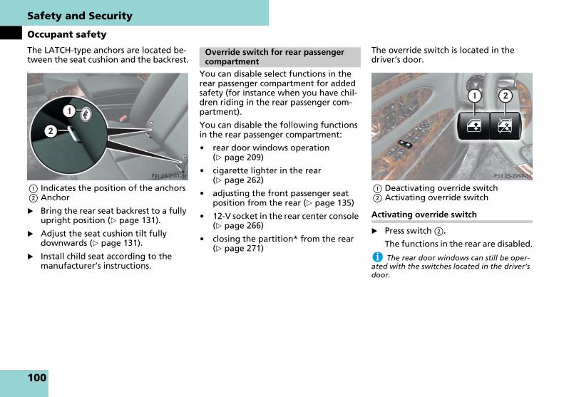
Safety and Security
Occupant safety
The LATCH-type anchors are located be-tween the seat cushion and the backrest.t.
1 Indicates the position of the anchors2 Anchor
� Bring the rear seat backrest to a fully upright position (� page 131).
� Adjust the seat cushion tilt fully downwards (� page 131).
� Install child seat according to the manufacturer’s instructions.
You can disable select functions in the rear passenger compartment for added safety (for instance when you have chil-dren riding in the rear passenger com-partment).
You can disable the following functions in the rear passenger compartment:
� rear door windows operation (� page 209)
� cigarette lighter in the rear (� page 262)
� adjusting the front passenger seat position from the rear (� page 135)
� 12-V socket in the rear center console (� page 266)
� closing the partition* from the rear (� page 271)
The override switch is located in the driver’s door.
1 Deactivating override switch2 Activating override switch
Activating override switch
� Press switch 2.
The functions in the rear are disabled.
i The rear door windows can still be oper-ated with the switches located in the driver’s door.
Override switch for rear passenger compartment
100

Safety and Security
Occupant safety
Deactivating override switch
� Press switch 1.
The functions in the rear are enabled again.
For information, see “Power windows” (� page 209).
Warning! G
Activate the override switch when children are riding in the back seats of the vehicle. The children may otherwise injure them-selves, e.g. by becoming trapped in the window opening.
When leaving the vehicle, always remove the SmartKey or SmartKey with KEYLESS-GO** from the starter switch, take it with you, and lock the vehicle. Do not leave children unattended in the vehi-cle, or with access to an unlocked vehicle. A child’s unsupervised access to a vehicle could result in an accident and/or serious personal injury.
101
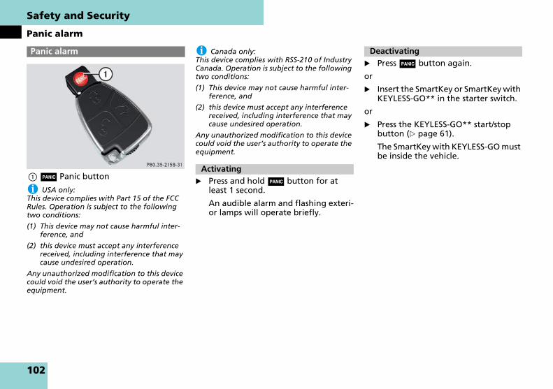
Safety and Security
Panic alarm
1 Â Panic button
i USA only:This device complies with Part 15 of the FCC Rules. Operation is subject to the following two conditions:
(1) This device may not cause harmful inter-ference, and
(2) this device must accept any interference received, including interference that may cause undesired operation.
Any unauthorized modification to this device could void the user’s authority to operate the equipment.
i Canada only:This device complies with RSS-210 of Industry Canada. Operation is subject to the following two conditions:
(1) This device may not cause harmful inter-ference, and
(2) this device must accept any interference received, including interference that may cause undesired operation.
Any unauthorized modification to this device could void the user’s authority to operate the equipment.
� Press and hold  button for at least 1 second.
An audible alarm and flashing exteri-or lamps will operate briefly.
� Press  button again.
or
� Insert the SmartKey or SmartKey with KEYLESS-GO** in the starter switch.
or
� Press the KEYLESS-GO** start/stop button (� page 61).
The SmartKey with KEYLESS-GO must be inside the vehicle.
Panic alarm
Activating
Deactivating
102

Safety and Security
Driving safety systems
In this section you will find information on the following driving safety systems:
� ABS (Antilock Brake System)
� BAS (Brake Assist System)
� ESP® (Electronic Stability Program)
� Electro-hydraulic brake system
i In winter operation, the maximum effec-tiveness of the ABS, BAS, ESP® and electro-hy-draulic brake system is only achieved with winter tires (M + S tires), or snow chains as re-quired.
The Antilock Brake System (ABS) regu-lates the brake pressure so that the wheels do not lock during braking. This allows you to maintain the ability to steer your vehicle.
The ABS is functional above a speed of approximately 5 mph (8 km/h) indepen-dent of road surface conditions.
On slippery road surfaces, the ABS will respond even to light brake pressure.
The - indicator lamp in the instru-ment cluster comes on when you switch on the ignition. It goes out when the en-gine is running.
Braking
If the ABS activates during braking, the ABS/ESP® warning lamp v in the in-strument cluster dial flashes. Because of the electro-hydraulic brake system, you will not feel any pulsation in the brake pedal.
� Keep firm and steady pressure on the brake pedal.
Continuous steady brake pedal pressure yields the advantages provided by the ABS, namely braking power and the ability to steer the vehicle.
The ABS/ESP® warning lamp v flashes whenever the ABS is activated which can be an indication of hazardous road con-ditions and functions as a reminder to take extra care while driving.
Emergency brake maneuver
� Keep continuous full pressure on the brake pedal.
Driving safety systems
Warning! G
The following factors increase the risk of accidents:
� Excessive speed, especially in turns
� Wet and slippery road surfaces
� Following another vehicle too closely
The ABS, BAS, ESP® and electro-hydraulic brake system cannot reduce this risk.
Always adjust your driving style to the pre-vailing road and weather conditions.
ABS
Warning! G
Do not pump the brake pedal. Use firm, steady brake pedal pressure instead. Pumping the brake pedal defeats the pur-pose of the ABS and significantly reduces braking effectiveness.
103

Safety and Security
Driving safety systems
For more information on ABS, see the “Practical hints” section (� page 354).
The Brake Assist System (BAS) operates in emergency situations. If you apply the brakes very quickly, the BAS automatical-ly provides full brake boost, thereby po-tentially reducing the braking distance.
� Apply continuous full braking pres-sure until the emergency braking sit-uation is over.
The ABS will prevent the wheels from locking.
When you release the brake pedal, the brakes function again as normal. The BAS is then deactivated.
Warning! G
When the ABS is malfunctioning, the BAS and the ESP® are also switched off.
When the ABS is malfunctioning, the wheels may lock during hard braking, re-ducing steering capability and extending the braking distance.
Warning! G
The ABS cannot prevent the natural laws of physics from acting on the vehicle, nor can it increase braking or steering efficien-cy beyond that afforded by the condition of the vehicle brakes and tires or the trac-tion afforded. The ABS cannot prevent ac-cidents, including those resulting from excessive speed in turns, following another vehicle too closely, or hydroplaning. Only a safe, attentive, and skillful driver can pre-vent accidents. The capabilities of an ABS equipped vehicle must never be exploited in a reckless or dangerous manner which could jeopardize the user’s safety or the safety of others.
BAS
Warning! G
If the BAS is malfunctioning, the brake sys-tem is still functioning normally, but with-out the additional brake boost available that BAS would normally provide in an emergency braking maneuver. Therefore, the braking distance may increase.
Warning! G
The BAS cannot prevent the natural laws of physics from acting on the vehicle, nor can it increase braking efficiency beyond that afforded by the condition of the vehi-cle brakes and tires or the traction. The BAS cannot prevent accidents, including those resulting from excessive speed in turns, following another vehicle too close-ly, or hydroplaning. Only a safe, attentive, and skillful driver can prevent accidents. The capabilities of a BAS equipped vehicle must never be exploited in a reckless or dangerous manner which could jeopardize the user’s safety or the safety of others.
104

Safety and Security
Driving safety systems
The Electronic Stability Program (ESP®) is operational as soon as the engine is run-ning and monitors the vehicle’s traction (force of adhesive friction between the tires and the road surface) and handling.
The ESP® recognizes when a wheel is spinning or if the vehicle starts to skid. By applying brakes to the appropriate wheel and by limiting engine output, the ESP® works to stabilize the vehicle. The ESP® is especially useful while driving off and on wet or slippery road surfaces. The ESP® also stabilizes the vehicle during braking and steering maneuvers.
The ABS/ESP® warning lamp v in the instrument cluster flashes when the ESP® is engaged.
The ABS/ESP® warning lamp v in the instrument cluster comes on when you switch on the ignition. It goes out when the engine is running.
! Because the ESP® operates automatically, the engine must be turn off (SmartKey in starter switch position 0 or 1 or KEYLESS-GO** start/stop button in position 0 or 1) when
� the parking brake is being tested on a brake test dynamometer
� the vehicle is being towed with the front/rear axle raised.
Active braking action through the ESP® may otherwise seriously damage the brake system.
i The ESP® will only function properly if you use wheels of the recommended tire size (� page 436).
For more information on ESP®, see the “Practical hints” section (� page 354) and (� page 368).
Electronic traction system
The electronic traction system is a com-ponent of the ESP®.
The electronic traction system improves the vehicle’s ability to utilize available traction, especially under slippery road conditions by applying the brakes to a spinning wheel.
ESP®
Warning! G
Never switch off the ESP® when you see the ABS/ ESP® warning lamp v flashing in the instrument cluster. In this case pro-ceed as follows:
� While driving off, apply as little throt-tle as possible.
� While driving, ease up on the accelera-tor.
� Adapt your speed and driving style to the prevailing road conditions.
Failure to observe these guidelines could cause the vehicle to skid.
The ESP® cannot prevent accidents result-ing from excessive speed.
Warning! G
The ESP® cannot prevent the natural laws of physics from acting on the vehicle, nor can it increase the traction afforded. The ESP® cannot prevent accidents, including those resulting from excessive speed in turns, or hydroplaning. Only a safe, atten-tive, and skillful driver can prevent acci-dents. The capabilities of an ESP® equipped vehicle must never be exploited
in a reckless or dangerous manner which could jeopardize the user’s safety or the safety of others.
105

Safety and Security
Driving safety systems
When you switch off the ESP®, the elec-tronic traction system is still enabled.
Switching off the ESP®
To improve the vehicle’s traction, turn off the ESP® in driving situations where it would be advantageous to have the drive wheels spin and thus cut into sur-faces for better grip such as:
� when driving with snow chains
� in deep snow
� in sand or gravel
When you switch off the ESP®
� the ESP® does not stabilize the vehi-cle
� the engine output is not limited, which allows the drive wheels to spin and thus cut into surfaces for better grip
� the traction control will still apply the brakes to a spinning wheel
� the ESP® continues to operate when you are braking
� you cannot activate the cruise control or the Distronic** system
� the cruise control or the Distronic** system switch off if currently activat-ed
i When the ESP® is switched off and one or more drive wheels are spinning, the ABS/ESP® warning lamp v in the instrument cluster flashes. However, the ESP® will then not stabi-lize the vehicle.
The ESP® switch is located on the lower part of the front center console.
1 ESP® switch
� With the engine running, press ESP® switch 1 until the ABS/ESP® warning lamp v in the instrument cluster comes on.
The ESP® is switched off.
Warning! G
If you are driving too fast, the electronic traction system cannot reduce the risk of an accident.
The electronic traction system cannot pre-vent the natural laws of physics from act-ing on the vehicle.
Warning! G
The ESP® should not be switched off dur-ing normal driving other than in the cir-cumstances described below. Disabling of the system will reduce vehicle stability in driving maneuvers.
Warning! G
Switch on the ESP® immediately if the aforementioned circumstances do not apply anymore. Otherwise the ESP® will not stabilize the vehicle when it is starting to skid or a wheel is spinning.
106

Safety and Security
Driving safety systems
! Avoid spinning of a drive wheel for an ex-tended period with the ESP® switched off. This may cause serious damage to the driv-etrain which is not covered by the Maybach Limited Warranty.
Switching on the ESP®
� Press ESP® switch 1 until the ABS/ESP® warning lamp v in the instru-ment cluster goes out.
You are now again in normal driving mode with the ESP® switched on.
The electro-hydraulic brake system com-bines a hydraulic brake circuit with elec-tronically controlled brake servo assistance. You have increased braking safety and improved braking comfort.
Warning! G
When the ABS/ESP® warning lamp v is illuminated continuously, the ESP® is switched off. Vehicle stability in standard driving maneuvers reduces.
Adapt your speed and driving to the pre-vailing road conditions and to the non-op-erating status of the ESP®.
Electro-hydraulic brake system
Warning! G
Never ignore a brake malfunction indicat-ed in the instrument cluster, for example by the ; (USA only) or 3 (Canada only) red brake warning lamp. Refer to the “Practical hints” section (� page 360). Also read and observe the messages in the in-strument cluster display (� page 364).
Warning! G
The electro-hydraulic brake system re-quires electrical power to operate.
A malfunction in the vehicle’s power sup-ply or electrical system may impair brake system operation and switch it into its emergency operation mode. In such a case, the red brake warning lamp (� page 360) and warning messages in the instrument cluster come on while driving (see page 378 to page 381). To brake, the driv-er must then apply significantly greater brake pedal pressure and depress the ped-al much further to obtain the expected braking effect. If necessary, apply full pres-sure to the brake pedal. Brakes may only be applied to the front wheels. Stopping distance is increased!
If there is a malfunction in the electro-hy-draulic brake system, we recommend that the vehicle be transported with all wheels off the ground using flatbed or appropri-ate wheel lift/dolly equipment. A tow bar must be used if circumstances do not per-mit the use of the recommended towing methods and the vehicle requires towing with all four wheels on the ground.
Towing the vehicle with all four wheels on the ground is only permissible for distances up to 30 miles (50 km) and at a speed not to exceed 30 mph (50 km/h). For more in-formation, refer to “Towing the vehicle” (� page 423).
107

Safety and Security
Driving safety systems
The electro-hydraulic brake system is au-tomatically activated when you:
� unlock the vehicle with the SmartKey or the KEYLESS-GO**
� open the driver’s or passenger door
� turn the SmartKey in the starter switch to position 1
� in vehicles with KEYLESS-GO**, press the start/stop button (� page 61) on gear selector lever once
� depress the brake pedal
� release the parking brake
i If the electro-hydraulic brake system is ac-tivated when the brake pedal is first de-pressed, you may feel a reduced pedal resistance and longer pedal travel than nor-mal. When releasing the pedal, you may also feel the brake pedal pulsate and you may hear a sound which is caused by the activation of the electro-hydraulic brake system pump. This is normal and not an indication of a malfunc-tion. Pedal travel returns to normal when you release the brake pedal and depress it again and the sound soon ceases.
If you experience a reduced pedal resistance and longer pedal travel while driving and the red brake warning lamp (� page 360) illumi-nates and/or warning messages appear in the instrument cluster (see page 378 to page 381), the brake system is malfunctioning. Follow
the instructions of the warning message(s) and have the brake system checked immedia-tely.
The electro-hydraulic brake servo assis-tance switches off automatically:
� approximately 20 seconds after you locked the vehicle from outside
� approximately 2 minutes after you
� turned the SmartKey in the starter switch to position 0 or removed the SmartKey
� pressed the KEYLESS-GO** start/stop button (� page 61) to turn off the engine or power supply and opened the driver’s door (with driver’s door open, the start-er switch is set to position 0, same as SmartKey removed from starter switch)
Warning! G
Have brake pad replacement and other work on the electro-hydraulic brake sys-tem carried out by qualified technicians only. Contact an authorized Maybach Stu-dio for further information. The electro-hydraulic brake system must be deactivat-ed prior to working on the system. High pressure is intermittently built up in the system as part of its automatic self-test. In addition, the system is automatically acti-vated when the vehicle is unlocked by re-mote control, when the driver’s or passenger door is opened, when the start-er switch is in position 1, when the brake pedal is depressed or when the parking brake is released. Failure to deactivate the system prior to maintenance will cause brake pistons to extend and brake fluid to leak, which may result in injuries (contu-sions and acid burns). Extended brake pis-tons may also cause injury.
108

Safety and Security
Driving safety systems
Note on driving with the electro-hydrau-lic brake system
� Following extended periods of only minor loads to your brake system, you should occasionally apply the brakes when traveling at high speeds. This improves the grip of the brake pads.
� After driving on wet or snow-covered roads, you should apply your brakes firmly before parking your vehicle. This produces heat which serves to dry the brake disks and help prevent corrosion.
� On long and steep grades, shift to a lower gear (gear range 1, 2 or 3) to prevent the brakes from overheating and to reduce brake wear.
� After hard braking, it is advisable to drive on for some time so that the air stream will cool down the brakes faster.
� Only components approved by us for use on Maybach vehicles (e.g. brake pads) should be installed on your ve-hicle. Brake pads not approved by us for use on Maybach vehicles may im-pair the safety of your vehicle.
Warning! G
Be very careful not to endanger other road users when you apply the brakes.
109

Safety and Security
Anti-theft systems
The immobilizer prevents unauthorized persons from starting your vehicle.
Activating
With the SmartKey
� Remove the SmartKey from the start-er switch.
With KEYLESS-GO**
� Turn off the engine by means of the KEYLESS-GO start/stop button (� page 61).
� Open the driver’s door.
Deactivating
� Switch on the ignition (� page 60).
i Starting the engine will also deactivate the immobilizer.
In case the engine cannot be started (yet the vehicle’s battery is charged), the system is not operational. Contact an authorized Maybach Studio or call 1-866-FOR-MAYBach (in the USA) or 1-888-881-6611 (in Canada).
Once the alarm system has been armed, a visual and audible alarm is triggered when someone opens
� a door
� the trunk
� the hood
The alarm will stay on even if the activat-ing element (a door, for example) is im-mediately closed.
The alarm system will also be triggered when
� someone attempts to raise the vehi-cle
� the vehicle is opened with the me-chanical key
� someone opens a door from the in-side
� someone opens the trunk with the emergency release button
i If the alarm stays on for more than 30 seconds, a call to the Response Center is ini-tiated automatically by the Tele Aid system provided Tele Aid service was subscribed to and properly activated, and that necessary cel-lular service and GPS coverage are available.
Arming the alarm system
The indicator lamp located below the hazard warning flasher switch in on the upper part of the front center console.
1 Indicator lamp
� Lock your vehicle with the SmartKey or KEYLESS-GO**.
The turn signal lamps flash three times to indicate that the alarm sys-tem is activated. The indicator lamp 1 flashes to indicate that the alarm system is armed.
Anti-theft systems
Immobilizer
Anti-theft alarm system
110
Safety and Security
Anti-theft systems
i If the turn signal lamps do not flash three times, one of the following elements may not be properly closed:
� a door
� the trunk
Close the respective element and lock the ve-hicle again.
Disarming the alarm system
� Unlock your vehicle.
The turn signal lamps flash once to in-dicate that the alarm system is dis-armed.
i The alarm system will rearm automatically again after approximately 40 seconds if no door was opened.
Canceling the alarm
With the SmartKey
� Insert the SmartKey in the starter switch.
or
� Press Œ or ‹ on the SmartKey.
With KEYLESS-GO**
� Grasp an outside door handle.
The SmartKey with KEYLESS-GO must be within 3 ft (1 m) of the vehicle.
or
� Press the KEYLESS-GO start/stop but-ton (� page 61).
The SmartKey with KEYLESS-GO must be inside the vehicle.
Once the tow-away alarm is armed, a vi-sual and audible alarm will be triggered when someone attempts to raise the ve-hicle.
i If the alarm stays on for more than 30 seconds, a call to the Response Center is ini-tiated automatically by the Tele Aid system provided Tele Aid service was subscribed to and properly activated, and that necessary cel-lular service and GPS coverage are available.
Arming the tow-away alarm
� Lock your vehicle with the SmartKey or KEYLESS-GO**.
The tow-away alarm is automatically armed after about 30 seconds.
Disarming the tow-away alarm
To prevent triggering the tow-away alarm feature, switch off the tow-away alarm before towing the vehicle, or when parking on a surface subject to movement, such as a ferry or auto train.
The button is located on the overhead control panel.
Tow-away alarm
111

Safety and Security
Anti-theft systems
1 Tow-away alarm off button
� Switch off the ignition and remove the SmartKey from the starter switch.
i You cannot disarm the tow-away alarm if the ignition is switched on.
� Press button 1.
The indicator lamp in the button comes on briefly.
� Exit the vehicle and lock it with the SmartKey or (vehicles with KEYLESS-GO**) with the lock button at each outside door handle or trunk lid.
i When you unlock your vehicle, the tow-away protection disarms automatically.
The tow-away alarm remains disarmed until you lock your vehicle again.
Canceling the alarm
With the SmartKey
� Insert the SmartKey in the starter switch.
or
� Press Œ or ‹ on the SmartKey.
With KEYLESS-GO**
� Grasp an outside door handle.
The SmartKey with KEYLESS-GO must be within 3 ft (1 m) of the vehicle.
or
� Press the KEYLESS-GO start/stop but-ton (� page 61).
The SmartKey with KEYLESS-GO must be inside the vehicle.
112

Controls in detail
Locking and unlocking
Seats
Memory function
Lighting
Instrument cluster
Control system
Automatic transmission
Good visibility
Automatic climate control
Power windows
Power tilt/sliding sunroof
Electrotransparent roof*
Driving systems
Loading
Useful features
113

Controls in detail
Locking and unlocking
In the “Controls in detail” section, you will find detailed information on how to operate the equipment installed on your vehicle. If you are already familiar with the basic functions of your vehicle, this section will be of particular interest to you.
To quickly familiarize yourself with the basic functions of the vehicle, refer to the “Getting started” section of this manual. The corresponding page num-bers are given at the beginning of each segment.
For more information on locking and un-locking, see “Getting started” (� page 58) and (� page 77).
Your vehicle comes supplied with two SmartKeys, each with remote control and a removable mechanical key.
The locking tabs for the mechanical key portion of the two SmartKeys are a dif-ferent color to help distinguish each SmartKey unit.
The SmartKey provides an extended op-erating range. To prevent theft, howev-er, it is advisable to only unlock the vehicle when you are in close proximity to it.
The SmartKey centrally locks and un-locks:
� the doors
� the trunk
� the fuel filler flap
SmartKey with remote control
1  Panic button (� page 102)2 ‹ Lock button3 Š Opening button for trunk4 Mechanical key locking tab5 Œ Unlock button6 Battery check lamp
! To prevent possible malfunction, avoid exposing the SmartKey to high levels of elec-tromagnetic radiation.
Locking and unlocking SmartKey
114
Controls in detail
Locking and unlocking
i USA only:This device complies with Part 15 of the FCC Rules. Operation is subject to the following two conditions:
(1) This device may not cause harmful inter-ference, and
(2) this device must accept any interference received, including interference that may cause undesired operation.
Any unauthorized modification to this device could void the user’s authority to operate the equipment.
i Canada only:This device complies with RSS-210 of Industry Canada. Operation is subject to the following two conditions:
(1) This device may not cause interference, and
(2) this device must accept any interference received, including interference that may cause undesired operation of the device.
Any unauthorized modification to this device could void the user’s authority to operate the equipment.
i When you unlock the vehicle, the electro-hydraulic brake system is activated (� page 107).
i You can also open and close the windows and the tilt/sliding sunroof using the SmartKey.
! If you can no longer lock or unlock the ve-hicle with the SmartKey, then either the bat-teries in the SmartKey are discharged, the SmartKey is malfunctioning or the vehicle bat-teries are drained.
� Check the batteries in the SmartKey and replace them if necessary (� page 405).
� Use the mechanical key to unlock the driv-er’s door (� page 401) and the trunk (� page 402).
� Use the mechanical key to lock the driver’s door (� page 401) and the trunk (� page 127).
� Have the vehicle batteries and their con-nections checked (� page 417).
If the SmartKey is malfunctioning, contact an authorized Maybach Studio.
Factory setting
Global unlocking
� Press button Œ.
All turn signal lamps flash once. The locking knobs in the doors move up. The anti-theft alarm system is dis-armed.
The vehicle will lock again automatically and rearm the anti-theft alarm system within approximately 40 seconds of un-locking if:
� neither a door nor the trunk is opened
� the SmartKey is not inserted in the starter switch
� the central locking switch is not acti-vated
Warning! G
When leaving the vehicle, always remove the SmartKey from the starter switch, take it with you, and lock the vehicle. Do not leave children unattended in the vehicle, or with access to an unlocked vehicle. It is possible for children to open a locked door from the inside, which could result in an accident and/or serious personal injury.
115

Controls in detail
Locking and unlocking
Global locking
� Press button ‹.
With the trunk and all doors closed, all turn signal lamps flash three times. The locking knobs in the doors move down. The anti-theft alarm system is armed.
Selective setting
If you frequently travel alone, you may wish to reprogram the SmartKey so that pressing Œ only unlocks the driver’s door and the fuel filler flap.
� Press and hold buttons Œ and ‹ simultaneously for about 5 seconds until battery check lamp 6 (� page 114) flashes twice.
The SmartKey will then function as follows:
Unlocking driver’s door and fuel filler flap
� Press button Œ once.
All turn signal lamps flash once. The locking knob in the driver’s door moves up. The anti-theft alarm sys-tem is disarmed.
Global unlocking
� Press button Œ twice.
All turn signal lamps flash once. The locking knobs in the doors move up. The anti-theft alarm system is dis-armed.
Global locking
� Press button ‹.
With the trunk and all doors closed, all turn signal lamps flash three times. The locking knobs in the doors move down. The anti-theft alarm system is armed.
Restoring to factory setting
� Press and hold buttons Œ and ‹ simultaneously for about 5 seconds until battery check lamp 6 flashes twice.
116

Controls in detail
Locking and unlocking
Vehicles equipped with KEYLESS-GO come with two SmartKeys with KEYLESS-GO, each with remote control and a removable mechanical key.
The locking tabs for the mechanical key portion of the two SmartKeys with KEYLESS-GO are a different color to help distinguish each SmartKey with KEYLESS-GO unit.
The KEYLESS-GO function is integrated into the SmartKey. On these vehicles, the validity of the SmartKey with KEYLESS-GO is checked every time you grasp an outside door handle.
If the SmartKey with KEYLESS-GO is val-id, your vehicle unlocks
� the doors
� the trunk
� the fuel filler flap
SmartKey with KEYLESS-GO
1  Panic button (� page 102)2 ‹ Lock button3 Š Opening button for trunk4 Mechanical key locking tab5 Œ Unlock button6 Battery check lamp
i When any outside door handle other than the driver’s outside door handle is grasped, the vehicle is centrally unlocked.
! To prevent possible malfunction, avoid exposing the SmartKey with KEYLESS-GO to high levels of electromagnetic radiation.
i USA only:This device complies with Part 15 of the FCC Rules. Operation is subject to the following two conditions:
(1) This device may not cause harmful inter-ference, and
(2) this device must accept any interference received, including interference that may cause undesired operation.
Any unauthorized modification to this device could void the user’s authority to operate the equipment.
SmartKey with KEYLESS-GO**Warning! G
When leaving the vehicle, always take the SmartKey with KEYLESS-GO with you and lock the vehicle. Do not leave children un-attended in the vehicle, or with access to an unlocked vehicle. It is possible for chil-dren to open a locked door from the in-side, which could result in an accident and or serious personal injury.
117

Controls in detail
Locking and unlocking
i Canada only:This device complies with RSS-210 of Industry Canada. Operation is subject to the following two conditions:
(1) This device may not cause interference, and
(2) this device must accept any interference received, including interference that may cause undesired operation of the device.
Any unauthorized modification to this device could void the user’s authority to operate the equipment.
i When you unlock the vehicle, the electro-hydraulic brake system is activated (� page 107).
i You can also open and close the windows and the tilt/sliding sunroof using the SmartKey with KEYLESS-GO.
! If you can no longer lock or unlock the ve-hicle with the SmartKey with KEYLESS-GO, then either the batteries in the SmartKey with KEYLESS-GO are discharged, the SmartKey with KEYLESS-GO is malfunctioning or the ve-hicle batteries are drained.
� Check the batteries in the SmartKey with KEYLESS-GO and replace them if necessary (� page 405).
� Use the mechanical key to unlock the driv-er’s door (� page 401) and the trunk (� page 402).
� Use the mechanical key to lock the driver’s door (� page 401) and the trunk (� page 127).
� Have the vehicle batteries and their con-nections checked (� page 417).
If the SmartKey with KEYLESS-GO is malfunc-tioning, contact an authorized Maybach Studio.
Important notes on using KEYLESS-GO
� You can also use the SmartKey with KEYLESS-GO like a normal SmartKey (� page 114).
� You can combine KEYLESS-GO func-tions with normal SmartKey functions (e.g. unlocking with KEYLESS-GO and locking with button ‹).
� Always carry the SmartKey with KEYLESS-GO with you.
� Never store the SmartKey with KEYLESS-GO together with:
� Electronic items such as a mobile phone or another SmartKey with KEYLESS-GO
� Metallic objects such as coins or metal foil
Doing so could impair the function of the KEYLESS-GO system.
� To lock or unlock the vehicle, the SmartKey with KEYLESS-GO must be located outside the vehicle within ap-proximately 3 ft (1 m) of a door or the trunk lid.
� If the vehicle has been parked for more than 72 hours, you must pull an outside door handle in order to acti-vate the KEYLESS-GO function.
118

Controls in detail
Locking and unlocking
� In order to start the engine with the SmartKey with KEYLESS-GO:
� The SmartKey with KEYLESS-GO must be located in the vehicle.
� The brake pedal must be firmly depressed. Do not depress the ac-celerator.
� If the SmartKey with KEYLESS-GO is positioned farther away from the ve-hicle, the system may no longer rec-ognize the SmartKey with KEYLESS-GO. The vehicle then cannot be locked or the engine started via the KEYLESS-GO system.
� If the SmartKey with KEYLESS-GO is removed from the vehicle (e.g. if pas-senger exits the vehicle with the SmartKey with KEYLESS-GO).
� when pressing the KEYLESS-GO start/stop button or trying to lock the vehicle with the outside door handle the message KEY NOT DETECTED appears in the multi-function display
� with the engine running, the mes-sage KEY NOT DETECTED appears in the multifunction display while driving off.
Find the SmartKey with KEYLESS-GO or change its present location imme-diately (e.g. place it on the front pas-senger seat or insert it in shirt pocket).
� If you have started the engine with the KEYLESS-GO start/stop button, you can turn it off again with:
� the KEYLESS-GO start/stop button
� the SmartKey inserted in the start-er switch, when gear selector le-ver in position P
� Remember that the engine can be started by anyone with a SmartKey with KEYLESS-GO that is left inside the vehicle.
Possibility 1: (One SmartKey with KEYLESS-GO in the vehicle, one SmartKey with KEYLESS-GO outside the vehicle): If you leave the SmartKey with KEYLESS-GO behind when exiting and locking the vehicle, no message appears in the multifunc-tion display.
Possibility 2: (One SmartKey with KEYLESS-GO in the vehicle, no SmartKey with KEYLESS-GO outside the vehicle): When exiting and trying to lock the vehicle, the message KEY STILL IN VEHICLE appears in the mul-tifunction display. The vehicle will not be locked.
119

Controls in detail
Locking and unlocking
Factory setting
Global unlocking
� Grasp an outside door handle.
All turn signal lamps flash once. The locking knobs in the doors move up. The anti-theft alarm system is dis-armed.
The vehicle will lock again automatically and rearm the anti-theft alarm system within approximately 40 seconds of un-locking if:
� neither a door nor the trunk is opened
� the central locking switch is not acti-vated
i The vehicle could be inadvertently un-locked if the SmartKey with KEYLESS-GO is within 3 ft (1 m) of the vehicle and
� an outside door handle is splashed with water, or
� you attempt to clean an outside door han-dle.
Global locking
� Press the lock button on an outside door handle (� page 80) or trunk lid (� page 121).
With the trunk and all doors closed, all turn signal lamps flash three times. The locking knobs in the doors move down. The anti-theft alarm system is armed.
i You can also lock the vehicle using the KEYLESS-GO lock button on the trunk lid (� page 121) or KEYLESS-GO locking/closing switch (� page 126).
Selective setting
If you frequently travel alone, you may wish to reprogram the SmartKey with KEYLESS-GO so when you grasp the driv-er’s outside door handle only the driver’s door and the fuel filler flap unlocks.
� Press and hold buttons Œ and ‹ simultaneously for about 5 seconds until battery check lamp 6 (� page 117) flashes twice.
The SmartKey with KEYLESS-GO will then function as follows:
Unlocking driver’s door and fuel filler flap
� Grasp the driver’s outside door han-dle.
All turn signal lamps flash once. The locking knob in the driver’s moves up. The anti-theft alarm system is dis-armed.
Global unlocking
� Grasp any outside door handle other than the driver’s outside door handle.
All turn signal lamps flash once. The locking knobs in the doors move up. The anti-theft alarm system is dis-armed.
Global locking
� Press the lock button on an outside door handle (� page 80).
With the trunk and all doors closed, all turn signal lamps flash three times. The locking knobs in the doors move down. The anti-theft alarm system is armed.
i You can also lock the vehicle using the KEYLESS-GO lock button on the trunk lid (� page 121) or KEYLESS-GO locking/closing switch (� page 126).
120

Controls in detail
Locking and unlocking
Restoring to factory setting
� Press and hold buttons Œ and ‹ simultaneously for about 5 seconds until battery check lamp 6 (� page 117) flashes twice.
Global locking using KEYLESS-GO lock button on the trunk lid
1 KEYLESS-GO lock button on trunk lid
� Press lock button 1.
With the trunk and all doors closed, all turn signal lamps flash three times. The locking knobs in the doors move down. The anti-theft alarm system is armed.
i You can also lock the vehicle using the lock button on an outside door handle (� page 80) or KEYLESS-GO locking/closing switch (� page 126).
� Press button Œ or ‹.
Battery check lamp 6 (� page 117) comes on briefly to indicate that the SmartKey or SmartKey with KEYLESS-GO batteries are in order.
! If battery check lamp 6 does not come on briefly during check, then the SmartKey or SmartKey with KEYLESS-GO batteries are dis-charged.
Replace the batteries (� page 405).
You can obtain the required batteries at any authorized Maybach Studio.
i If the batteries are checked within signal range of the vehicle, pressing button Œ or ‹ will lock or unlock the vehicle according-ly.
If you lose a SmartKey, SmartKey with KEYLESS-GO or mechanical key, you should do the following:
� Have the SmartKey or SmartKey with KEYLESS-GO deactivated by an au-thorized Maybach Studio.
� Report the loss of the SmartKey, SmartKey with KEYLESS-GO or the mechanical key immediately to your car insurance company.
� If necessary, have the mechanical lock replaced.
Your authorized Maybach Studio will be glad to supply you with a replacement.
Checking batteries in the SmartKey or SmartKey with KEYLESS-GO**
Loss of the SmartKey or SmartKey with KEYLESS-GO**
121

Controls in detail
Locking and unlocking
You can open a locked door from the in-side. Open door only when conditions are safe to do so.
1 Locking knob2 Inside door handle
i If the vehicle has previously been locked using the SmartKey or KEYLESS-GO**, open-ing a door from the inside will trigger the anti-theft alarm system.
To cancel the alarm, do one of the following:
� Press button Œ or ‹ on the SmartKey.
� Insert the SmartKey in the starter switch.
In vehicles with KEYLESS-GO**:
� Grasp an outside door handle.
The SmartKey with KEYLESS-GO must be within 3 ft (1 m) of the vehicle.
� Press the KEYLESS-GO** start/stop button (� page 61).
The SmartKey with KEYLESS-GO must be inside the vehicle.
i If you hear a warning signal you have for-gotten to switch off the headlamps before opening the driver’s door.
In addition the message TURN OFF LIGHTS ap-pears in the multifunction display.
Switch off the headlamps.
Front doors
� Pull on door handle 2 on the respec-tive front door to open door.
If door was locked, locking knob 1 will move up.
Rear doors
� Pull up locking knob 1 on the re-spective rear door to unlock door.
� Pull on door handle 2 on the respec-tive rear door to open door.
Opening the doors from the inside
122

Controls in detail
Locking and unlocking
You can close the rear doors automati-cally.
The remote rear door closing switch is above the rear door.
1 Remote rear door closing switch
� Pull switch 1 until the door is com-pletely closed.
� If necessary, pull the door into its lock by hand.
� Release switch 1 to interrupt proce-dure.
i You can also close the rear doors by hand.
You can open the trunk from the inside if the vehicle is stationary.
A minimum height clearance of 6.2 ft (1.89 m) is required to open the trunk lid.
! The trunk lid swings open automatically. Always make sure there is sufficient overhead clearance.
Closing the rear doors automatically from the inside (Maybach 62)
Warning! G
Only drive with the doors closed. Other-wise, one or more of the doors could open while the vehicle is in motion, putting you and/or others at risk.
Warning! G
To prevent possible personal injury, always keep hands and fingers away from the door opening when closing the door. Be especially careful when small children are around.
In case of danger, release the remote rear door closing switch to stop the closing pro-cedure.
Opening the trunk
Warning! G
Make sure the trunk is closed when the en-gine is running and while driving. Among other dangers, such as blocked visibility, exhaust fumes may enter the vehicle inte-rior. These fumes are damaging to your health.
123

Controls in detail
Locking and unlocking
Opening the trunk from the outside
1 Handle
� Press and hold button Š on the SmartKey or SmartKey with KEYLESS-GO** until the trunk un-locks and begins to open.
or
� Pull on handle 1.
In vehicles without KEYLESS-GO**: The vehicle must be unlocked.
! To stop the opening procedure, press button Š on the SmartKey or SmartKey with KEYLESS-GO**.
i If the trunk does not open, it is still locked separately (� page 127).
Opening the trunk from the inside
1 Remote trunk opening/closing switch
� Pull switch 1 until the trunk lid begins to open.
The trunk opens. You will see the symbol Ê in the multifunction dis-play until you close the trunk.
! To stop the opening procedure, press or pull trunk opening/closing switch 1.
i If the trunk does not open, it is still locked separately (� page 127).
i Do not place the SmartKey in the open trunk. You may lock yourself out.
i If the vehicle was previously centrally locked, the trunk will lock automatically after closing it. All turn signal lamps flash three times to confirm locking.
Vehicles with KEYLESS-GO**: To prevent a possible inadvertent lockout, the trunk will open automatically if a SmartKey with KEYLESS-GO** is recognized inside the vehicle or in the trunk.
The vehicle is only locked when the turn sig-nals flash three times. If you are carrying a sec-ond SmartKey with KEYLESS-GO** with you, you can still lock the vehicle.
If the trunk lid comes into contact with an ob-ject while closing (e.g. luggage that has been piled too high) in the upper motion sequence, the closing procedure is stopped and the trunk re-opens slightly.
Closing the trunk
Warning! G
Make sure the trunk is closed when the en-gine is running and while driving. Among other dangers, such as blocked visibility, exhaust fumes may enter the vehicle inte-rior. These fumes are damaging to your health.
124

Controls in detail
Locking and unlocking
Closing the trunk from the inside
1 Remote trunk opening/closing switch
� Press and hold switch 1 until the symbol Ê disappears from the mul-tifunction display and the trunk is closed.
To interrupt the closing procedure:
� Release the remote trunk opening/closing switch.
i You can also close the trunk by hand.
Closing the trunk from the outside automatically
Warning! G
Maintain sight of trunk area while operat-ing the remote trunk opening/closing switch. Monitor the closing procedure carefully to make sure no one is in danger of being injured. To interrupt the closing procedure, release the remote trunk open-ing/closing switch.
Even with the SmartKey or SmartKey with KEYLESS-GO** removed from the starter switch or the SmartKey with KEYLESS-GO** removed from the vehicle, the remote trunk opening/closing switch can be operated. Therefore, do not leave children unattended in the vehicle, or with access to an unlocked vehicle. A child’s un-supervised access to a vehicle could result in an accident and/or serious personal inju-ry.
Warning! G
Monitor the closing procedure carefully to make sure no one is in danger of being in-jured. To prevent possible personal injury, always keep hands and fingers away from the trunk opening when closing the trunk. Be especially careful when small children are around. To stop the closing procedure, do one of the following:
� press button Š on the SmartKey or SmartKey with KEYLESS-GO**
� press or pull the remote trunk open-ing/closing switch 1 (on the dash-board to the left of the steering wheel)
� press the KEYLESS-GO** locking/clos-ing switch 1 (� page 126)
� pull the trunk lid handle
Even with the SmartKey removed from the starter switch, the trunk closing switch can be operated. Therefore, do not leave chil-dren unattended in the vehicle, or with ac-cess to an unlocked vehicle. A child’s unsupervised access to a vehicle could re-sult in an accident and/or serious personal injury.
125

Controls in detail
Locking and unlocking
You can close the trunk separately.
Vehicles without KEYLESS-GO**
1 Trunk closing switch
Vehicles with KEYLESS-GO**
1 Trunk closing switch
� Press switch 1 briefly.
The trunk closes.
i You can also close the trunk by hand.
Closing the trunk and locking the vehicle from the outside (vehicles with KEYLESS-GO**)
You can close the trunk and lock the ve-hicle simultaneously.
1 KEYLESS-GO locking/closing switch
� Make sure you have the SmartKey with KEYLESS-GO with you.
� Press switch 1 briefly.
With all doors closed, the locking knobs in the doors move down and the trunk starts to close automatical-ly.
All turn signal lamps flash three times to confirm locking once the trunk has closed completely. The anti-theft alarm system is armed.
i You can also close the trunk by hand.
126

Controls in detail
Locking and unlocking
With the emergency release button, the trunk can be opened from inside the trunk.
1 Emergency release button
� Briefly press emergency release button 1.
The trunk unlocks and opens slightly.
� Push up the trunk lid to fully open.
i The emergency release button unlocks the trunk while the vehicle is standing still or in motion.
Illumination of the emergency release button:
� The button flashes for 30 minutes af-ter opening the trunk.
� The button flashes for 60 minutes af-ter closing the trunk.
i The emergency release button does not unlock the trunk if the vehicle battery is dis-charged or disconnected.
i If the vehicle has previously been locked using the SmartKey or KEYLESS-GO**, open-ing the trunk from the inside using the emer-gency release button will trigger the anti-theft alarm system.
To cancel the alarm, do one of the following:
� Press button Œ or ‹ on the SmartKey.
� Insert the SmartKey in the starter switch.
Vehicles with KEYLESS-GO**:
� Grasp an outside door handle.
The SmartKey with KEYLESS-GO must be within 3 ft (1 m) of the vehicle.
� Press the KEYLESS-GO start/stop button (� page 61).
The SmartKey with KEYLESS-GO must be inside the vehicle.
i To deny any unauthorized person access to the trunk, e.g. when you valet park the ve-hicle, lock it separately with the mechanical key. Leave only the SmartKey or SmartKey with KEYLESS-GO** less its mechanical key with the vehicle.
1 Neutral position2 Locked
� Close the trunk (� page 124).
� Remove the mechanical key from the SmartKey (� page 401).
� Insert the mechanical key in the trunk lid lock.
� Turn the mechanical key clockwise to position 2 and remove the mechani-cal key in that position to lock the trunk.
Trunk emergency release Valet trunk
127

Controls in detail
Locking and unlocking
The trunk remains locked even when the vehicle is centrally unlocked.
i You can only cancel the separate trunk locking mode by means of the mechanical key.
� Turn the mechanical key counter-clockwise to neutral position 1 (� page 127) and remove the me-chanical key in that position to un-lock the trunk.
You can now open the trunk (� page 123).
It is not necessary to slam the door or trunk lid closed. A pneumatic power as-sist mechanism draws doors and trunk lid closed quietly and automatically once the door or trunk lid has been latched. When the pneumatic power-assisted mechanism has stopped, doors and/or trunk can be re-opened.
Power closing assist for doors
� Press the doors gently past the initial engage position into the lock.
The doors close automatically.
Power closing assist for trunk lid
� Press the trunk lid gently into its lock.
The trunk closes automatically.
Power closing assist for doors and trunk lid
Warning! G
To prevent possible personal injury, always keep hands and fingers away from the door or trunk opening when closing a door or the trunk. Be especially careful when small children are around.
In case of danger, pull the respective inside or outside door handle, or pull on trunk lid handle.
To prevent personal injury, never activate the closing assist mechanism by tampering with the door or trunk lid latch.
Warning! G
Only drive with the doors closed. Other-wise, one or more of the doors could open while the vehicle is in motion, putting you and/or others at risk.
Warning! G
Only drive with the trunk closed as, among other dangers such as blocked visibility, ex-haust fumes may enter the vehicle interior.
128
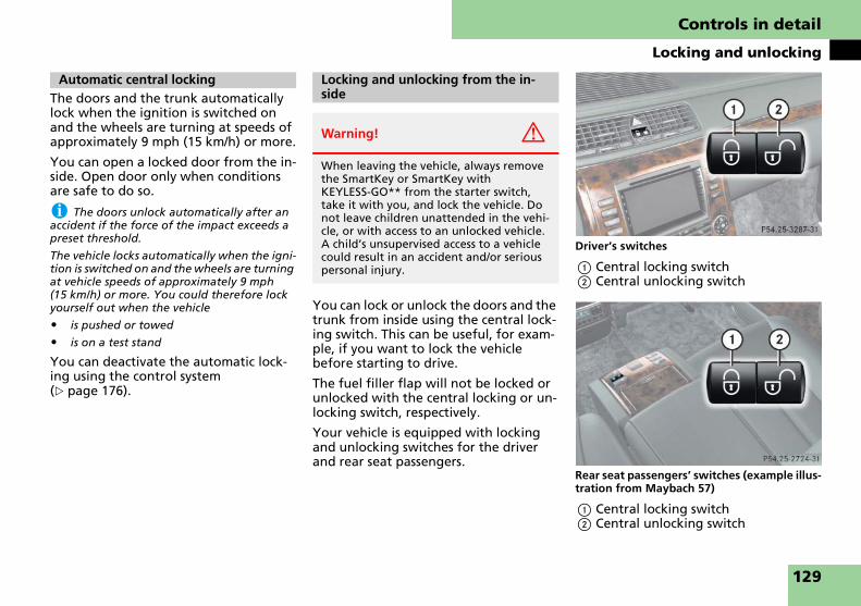
Controls in detail
Locking and unlocking
The doors and the trunk automatically lock when the ignition is switched on and the wheels are turning at speeds of approximately 9 mph (15 km/h) or more.
You can open a locked door from the in-side. Open door only when conditions are safe to do so.
i The doors unlock automatically after an accident if the force of the impact exceeds a preset threshold.
The vehicle locks automatically when the igni-tion is switched on and the wheels are turning at vehicle speeds of approximately 9 mph (15 km/h) or more. You could therefore lock yourself out when the vehicle
� is pushed or towed
� is on a test stand
You can deactivate the automatic lock-ing using the control system (� page 176).
You can lock or unlock the doors and the trunk from inside using the central lock-ing switch. This can be useful, for exam-ple, if you want to lock the vehicle before starting to drive.
The fuel filler flap will not be locked or unlocked with the central locking or un-locking switch, respectively.
Your vehicle is equipped with locking and unlocking switches for the driver and rear seat passengers.
Driver’s switches
1 Central locking switch2 Central unlocking switch
Rear seat passengers’ switches (example illus-tration from Maybach 57)
1 Central locking switch2 Central unlocking switch
Automatic central locking Locking and unlocking from the in-side
Warning! G
When leaving the vehicle, always remove the SmartKey or SmartKey with KEYLESS-GO** from the starter switch, take it with you, and lock the vehicle. Do not leave children unattended in the vehi-cle, or with access to an unlocked vehicle. A child’s unsupervised access to a vehicle could result in an accident and/or serious personal injury.
129

Controls in detail
Locking and unlocking
Rear seat passenger switches (Maybach 57 with rear center seat*)
1 Central locking switch2 Central unlocking switch
Rear seat passenger switches (Maybach 62 with rear center seat*)
1 Central locking switch2 Central unlocking switch
Locking
� Press central locking switch 1.
If all doors are closed, the vehicle locks.
Unlocking
� Press central unlocking switch 2.
The vehicle unlocks.
i You can open a locked door from inside at any time. Open door only when conditions are safe to do so.
If the vehicle was previously centrally locked using the SmartKey or KEYLESS-GO**, it will not unlock using the central unlocking switch 2.
If the vehicle was previously locked with the central locking switch 1:
� and the SmartKey or SmartKey with KEYLESS-GO** is set to factory settings, the complete vehicle is unlocked when a door is opened from the inside
� and the SmartKey or SmartKey with KEYLESS-GO** is set to selective settings, only the door opened from the inside is unlocked
130

Controls in detail
Seats
For more information on seat adjust-ment, see “Adjusting” (� page 62).
Head restraint tilt
For information on front seat head re-straint adjustment, see “Adjusting” (� page 64).
Maybach 57
1 Head restraints2 Head restraint side cushions
Seats
Rear seats
Warning! G
Never ride in a moving vehicle with the seat back in an excessively reclined posi-tion as this can be dangerous. You could slide under the seat belt in a collision. If you slide under it, the seat belt would ap-ply force at the abdomen or neck. That could cause serious or fatal injuries. The seat backrest and seat belts provide the best restraint when the wearer is in a near-ly upright position and seat belts are prop-erly positioned on the body.
Only the reclining seat (in Maybach 62 rear cabin) can be used in a reclined position with seat belts properly fastened while the vehicle is in motion. The reclining seat in the Maybach 62 rear cabin includes a seat belt system and kinematic electronic con-trols that are designed to maintain proper support and restraint-system effectiveness in all seat settings in the event of a collision or similar situation.
Your seat must be adjusted so that you can correctly fasten your seat belt (� page 68).
Never place hands under the seat or near any moving parts while a seat is being ad-justed.
Warning! G
For your protection, drive only with prop-erly positioned head restraints.
Adjust the head restraint so that it is as close to the head as possible and the cen-ter of the head restraint supports the back of the head at eye level. This will reduce the potential for injury to the head and neck in the event of an accident or similar situation.
Do not drive the vehicle without the seat head restraints. Head restraints are intend-ed to help reduce injuries during an acci-dent.
Warning! G
When leaving the vehicle, always remove the SmartKey or SmartKey with KEYLESS-GO** from the starter switch, take it with you, and lock the vehicle.
The seats can also be operated with the re-spective door is open. Therefore, do not leave children unattended in the vehicle, or with access to an unlocked vehicle. A child’s unsupervised access to a vehicle could result in an accident and/or serious personal injury.
131

Controls in detail
Seats
Maybach 62
1 Head restraints2 Head restraint side cushions
� Adjust the side cushions of the head restraints by hand.
� In addition to adjusting the head re-straint tilt using the corresponding power control on the rear door con-trol panel, the angle of the head re-straint can also be adjusted manually. Push or pull on the lower edge of the head restraint cushion.
i Adjust the head restraint in such a way that it is as close to the head as possible.
Rear seat adjustment (Maybach 57)
i To adjust settings for the right rear pas-senger seat, make sure the right rear passen-ger seat adjustment button is selected (� page 135).
i The memory function (� page 140) lets you store settings for the seat positions.
i The rear center seat* cannot be adjusted.
! When moving the seat, make sure there are no items in the footwell or behind the seats. Otherwise you could damage the seats.
1 Head restraint height2 Head restraint tilt3 Seat backrest tilt4 Seat fore and aft adjustment5 Seat cushion tilt
� Switch on the ignition (� page 60).
or
� Open the respective door.
Head restraint height
� Press switch up or down in direction of arrow 1.
Head restraint tilt
� Press switch forward or backward in direction of arrow 2.
Seat backrest tilt
� Press switch forward or backward in direction of arrow 3 until your arms are slightly angled when holding the steering wheel.
i Tilt the seat backrest to the rear for easier removal and installation of the head re-straints.
i The functions for adjusting backrest tilt and seat fore and aft are linked functions. When the seat is adjusted fore and aft, the backrest tilt is adjusted simultaneously, and vice versa.
Seat fore and aft adjustment
� Press switch forward or backward in direction of arrow 4.
Seat cushion tilt
� Press switch up or down in direction of arrow 5 until your upper legs are lightly supported.
132

Controls in detail
Seats
Rear seat adjustment (Maybach 62)
i To adjust settings for the right rear pas-senger seat, make sure the right rear passen-ger seat adjustment button is selected (� page 135).
i The memory function (� page 140) lets you store settings for the seat positions.
! When moving the seat, make sure there are no items in the footwell or behind the seats. Otherwise you could damage the seats.
i The rear center seat* cannot be adjusted.1 Fully reclined position2 Upright position3 Head restraint height4 Head restraint tilt5 Seat backrest tilt6 Seat cushion depth7 Seat cushion tilt8 Seat fore and aft adjustment9 Leg rest lengtha Leg rest tilt
� Switch on the ignition (� page 60).
or
� Open the respective door.
Fully reclined/upright position
� To adjust seat to fully reclined posi-tion, press switch 1.
� Press and hold switch 1 until seat is in desired position.
To stop the seat adjustment proce-dure, release switch 1.
� To adjust seat to upright position, press switch 2.
� Press and hold switch 2 until seat is in desired position.
To stop the seat adjustment proce-dure, release switch 2.
Head restraint height
� Press switch up or down in direction of arrow 3.
Head restraint tilt
� Press switch forward or backward in direction of arrow 4 (� page 133).
Seat backrest tilt
� Press switch forward or backward in direction of arrow 5 until your arms are slightly angled when holding the steering wheel.
i The functions for adjusting backrest tilt and seat fore and aft are linked functions. When the seat is adjusted fore and aft, the backrest tilt is adjusted simultaneously, and vice versa. ��
133

Controls in detail
Seats
�
Seat cushion depth� Press switch forward or backward in direction of arrow 6 until your legs are supported comfortably.
Seat cushion tilt
� Press switch up or down in direction of arrow 7 until your upper legs are lightly supported.
Seat fore and aft adjustment
� Press switch forward or backward in direction of arrow 8 (� page 133).
Leg rest length
� Press switch up or down in direction of arrow 9 (� page 133) to adjust the leg rest length.
Leg rest tilt
� Press switch up or down in direction of arrow a (� page 133) to adjust the leg rest tilt.
Extending and retracting the rear seat head restraints
1 Switch for rear seat head restraints
� Switch on the ignition (� page 60).
i You can only retract the rear seat head re-straints when no rear seat passenger is wear-ing a seat belt.
Retracting rear seat head restraints
� Press switch 1.
The rear seat head restraints retract.
Extending rear seat head restraints
� Press switch 1 again.
The rear outer seat head restraints extend to your last set position.
or
� Adjust the head restraints with the seat adjustment switches in the rear passenger compartment.
i When you fasten your seat belt in the rear, the respective rear outer seat head re-straint extends to your last set position.
i The rear center seat* head restraint can-not be extended using the switch in the front center console. Use the switch on the lower right side of the rear center seat.
�
Warning! G
For safety reasons, always drive with the rear seat head restraints in the extended position when the rear seats are occupied.
Keep the area around head restraints clear of articles (e.g. clothing) to not obstruct the retracting/extending operation of the head restraints.
134

Controls in detail
Seats
Rear center seat* head restraint adjust-ment
Example illustration from Maybach 57
1 Extending2 Retracting
� Switch on the ignition (� page 60).
or
� Open a rear door.
� Press switch 1 and hold it.
The rear seat head restraint extends until you release the switch.
� Press switch 2 and hold it.
The rear seat head restraint retracts until you release the switch.
This function lets you adjust the position of the front passenger seat from the right rear passenger seat.
Example illustration from Maybach 57
1 Front passenger seat adjustment2 Right rear passenger seat adjustment3 Seat fore and aft adjustment4 Seat cushion tilt5 Seat backrest tilt6 Head restraint height
Warning! G
For your protection, drive only with prop-erly positioned head restraints.
Adjust the head restraint so that it is as close to the head as possible and the cen-ter of the head restraint supports the back of the head at eye level. This will reduce the potential for injury to the head and neck in the event of an accident or similar situation.
Do not drive the vehicle without the seat head restraints. Head restraints are intend-ed to help reduce injuries during an acci-dent.
When leaving the vehicle, always remove the SmartKey or SmartKey with KEYLESS-GO** from the starter switch, take it with you, and lock the vehicle.
Even with the SmartKey or SmartKey with KEYLESS-GO** removed from the starter switch or the SmartKey with KEYLESS-GO** removed from the vehicle, the rear center seat head restraint can be operated when a rear door is open. There-fore, do not leave children unattended in the vehicle, or with access to an unlocked vehicle. A child’s unsupervised access to a vehicle could result in an accident and/or serious personal injury.
Setting front passenger seat position from rear
135

Controls in detail
Seats
! Do not move the front passenger seat completely forward if objects are stored in the front passenger-side footwell.
� Switch on the ignition (� page 60).
or
� Open the right rear passenger door.
� Press switch 1 (� page 135).
� Adjust passenger seat to desired posi-tion using switches 3 (� page 135) through 6 (� page 135).
� To adjust right rear passenger seat, press button 2 (� page 135).
i If you simultaneously operate an adjust-ment switch in the rear and on the front pas-senger side, no adjustment will take place.
i Maybach 62:If the rear seat is in reclined position, the ad-justment of the front passenger’s
� seat backrest and
� longitudinal position
toward the rear is restricted.
i Adjusting the front passenger seat posi-tion from the rear is not possible if you acti-vate the override switch (� page 100).
The multicontour seat has a movable seat cushion and inflatable air cushions built into the seat backrest to provide ad-ditional lumbar and side support.
The seat cushion movement, seat back-rest cushion height and curvature can be continuously varied with switches on the right side of the seat on the driver side, or the left side of the seat on the passen-ger side.
i Vehicles with rear center seat*: The rear center seat is not a multicontour seat.
Driver’s seat/front passenger seat
1 Lumbar region support 2 Shoulder region support3 Side bolster adjustment4 Massage function (PULSE)
Warning! G
When adjusting the front passenger seat, make sure the seat, if occupied, is as far from the passenger front airbag as possi-ble.
Otherwise, the passenger could be seriously or even fatally injured in the event of an accident or braking maneuver.
Make sure no one can be caught or injured while the seat is being adjusted.
Even with the SmartKey or SmartKey with KEYLESS-GO** removed from the starter switch or the SmartKey with KEYLESS-GO** removed from the vehicle, the power seats can be operated when the respective door is open. Therefore, do not leave children unattended in the vehicle, or with access to an unlocked vehicle. A child’s unsupervised access to a vehicle could result in an accident and/or serious personal injury.
Multicontour seats
136
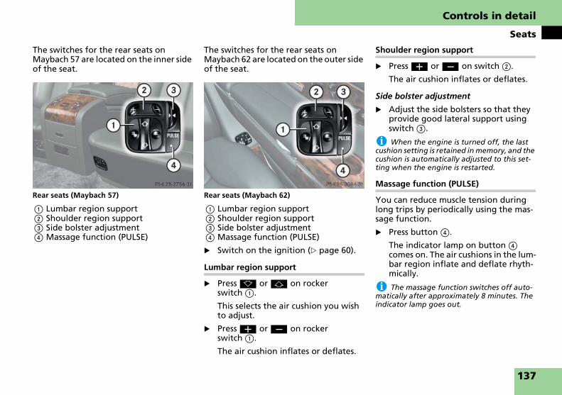
Controls in detail
Seats
The switches for the rear seats on Maybach 57 are located on the inner side of the seat.
Rear seats (Maybach 57)
1 Lumbar region support 2 Shoulder region support3 Side bolster adjustment4 Massage function (PULSE)
The switches for the rear seats on Maybach 62 are located on the outer side of the seat.
Rear seats (Maybach 62)
1 Lumbar region support 2 Shoulder region support3 Side bolster adjustment4 Massage function (PULSE)
� Switch on the ignition (� page 60).
Lumbar region support
� Press k or j on rocker switch 1.
This selects the air cushion you wish to adjust.
� Press æ or ç on rocker switch 1.
The air cushion inflates or deflates.
Shoulder region support
� Press æ or ç on switch 2.
The air cushion inflates or deflates.
Side bolster adjustment
� Adjust the side bolsters so that they provide good lateral support using switch 3.
i When the engine is turned off, the last cushion setting is retained in memory, and the cushion is automatically adjusted to this set-ting when the engine is restarted.
Massage function (PULSE)
You can reduce muscle tension during long trips by periodically using the mas-sage function.
� Press button 4.
The indicator lamp on button 4 comes on. The air cushions in the lum-bar region inflate and deflate rhyth-mically.
i The massage function switches off auto-matically after approximately 8 minutes. The indicator lamp goes out.
137

Controls in detail
Seats
The red indicator lamps in the switch show the heating level selected.
i The rear center seat* cannot be heated.
Example illustration from Maybach with seat ventilation*
1 Seat heating switch
� Switch on the ignition (� page 60).
Switching on seat heating
� Press switch 1.
Three red indicator lamps in the switch come on.
� Continue pressing switch 1 until de-sired seat heating level is reached.
Switching off seat heating
� Press switch 1 repeatedly until all in-dicator lamps in the switch go out.
i If one or all of the lamps on the seat heat-ing switch are flashing, there is insufficient voltage due to too many electrical consumers are turned on. The seat heating switches off automatically.
The seat heating will switch back on again au-tomatically as soon as sufficient voltage is available.
Seat heating
Level
3 Three indicator lamps on (highest level).
After approximately 5 minutes, seat heating is au-tomatically switched to level 2.
2 Two indicator lamps on.
After approximately 10 minutes, seat heating is au-tomatically switched to level 1.
1 One indicator lamp on (lowest level).
After approximately 20 minutes, seat heating is au-tomatically switched off.
off No indicator lamp on.
138

Controls in detail
Seats
The blue indicator lamps in the switch show the ventilation level selected:
i The rear center seat* cannot be ventilat-ed.
1 Seat ventilation switch
� Switch on the ignition (� page 60).
Switching on seat ventilation
� Press switch 1.
Three blue indicator lamps in the switch come on.
� Continue pressing switch 1 until the desired seat ventilation level is reached.
i The seat ventilation for the driver’s seat can be activated using summer opening fea-ture (� page 211).
Switching off seat ventilation
� Press switch 1 (� page 139) repeat-edly until all indicator lamps go out.
i If one or all of the lamps flash on the seat ventilation switch, there is insufficient voltage due to too many electrical consumers being switched on. The seat ventilation switches off automatically.
The seat ventilation will switch back on again automatically as soon as sufficient voltage is available.
Seat ventilation*
Level
3 Three indicator lamps on (highest level).
2 Two indicator lamps on.
1 One indicator lamp on (lowest level).
off No indicator lamp on.
139
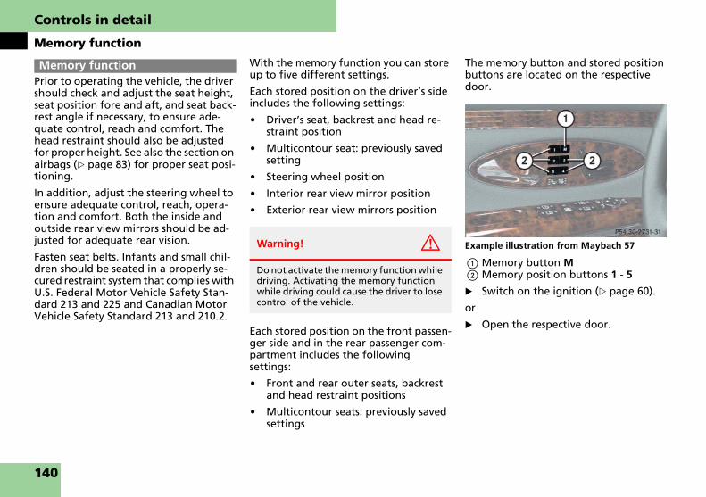
Controls in detail
Memory function
Prior to operating the vehicle, the driver should check and adjust the seat height, seat position fore and aft, and seat back-rest angle if necessary, to ensure ade-quate control, reach and comfort. The head restraint should also be adjusted for proper height. See also the section on airbags (� page 83) for proper seat posi-tioning.
In addition, adjust the steering wheel to ensure adequate control, reach, opera-tion and comfort. Both the inside and outside rear view mirrors should be ad-justed for adequate rear vision.
Fasten seat belts. Infants and small chil-dren should be seated in a properly se-cured restraint system that complies with U.S. Federal Motor Vehicle Safety Stan-dard 213 and 225 and Canadian Motor Vehicle Safety Standard 213 and 210.2.
With the memory function you can store up to five different settings.
Each stored position on the driver’s side includes the following settings:
� Driver’s seat, backrest and head re-straint position
� Multicontour seat: previously saved setting
� Steering wheel position
� Interior rear view mirror position
� Exterior rear view mirrors position
Each stored position on the front passen-ger side and in the rear passenger com-partment includes the following settings:
� Front and rear outer seats, backrest and head restraint positions
� Multicontour seats: previously saved settings
The memory button and stored position buttons are located on the respective door.
Example illustration from Maybach 57
1 Memory button M2 Memory position buttons 1 - 5
� Switch on the ignition (� page 60).
or
� Open the respective door.
Memory function
Warning! G
Do not activate the memory function while driving. Activating the memory function while driving could cause the driver to lose control of the vehicle.
140

Controls in detail
Memory function
� Adjust the seats, steering wheel and mirrors to the desired position (� page 62).
� On the driver’s side: adjust the steer-ing wheel (� page 64) and the rear view mirrors (� page 66) to the de-sired position.
� Press memory button M.
� Release memory button M and push memory position button 1, 2, 3, 4 or 5 within 3 seconds.
All the settings are stored at the se-lected position.
! Do not operate the power seats using the memory button if the seat backrest is in an ex-tremely reclined position. Doing so could cause damage to front or rear seats.
First move seat backrest to an upright posi-tion.
� Press and hold memory position button 1, 2, 3, 4 or 5 until the seat, steering wheel and mirrors have fully moved to the stored positions.
i Releasing the button immediately stops movement to the stored positions.
For easier parking you can adjust the pas-senger exterior rear view mirror so that you can see the right rear wheel as soon as you engage reverse gear R.
For information on activating the park-ing position, see “Activating exterior rear view mirror parking position” (� page 187).
The buttons are located on the driver’s door.
1 Exterior rear view mirror (passenger-side)
2 Adjustment button3 Memory button M
� Stop the vehicle in a safe location.
� Make sure the ignition is switched on (� page 60).
� Press button 1.
The passenger-side exterior rear view mirror is selected.
� Adjust the exterior rear view mirror with button 2 so that you see the rear wheel and the road curb.
� Press memory button 3.
� Within 3 seconds, press bottom of ad-justment button 2.
The parking position is stored if the mirror does not move.
i If the mirror does move, repeat the above steps. After the setting is stored, you can move the mirror again.
Storing positions in memory
Recalling positions from memory
Storing exterior rear view mirror parking position
141

Controls in detail
Lighting
For information on how to switch on the headlamps and use the turn signals, see “Switching on headlamps” (� page 73) and “Turn signals” (� page 74).
i If you drive in countries where vehicles drive on the other side of the road than the country where the vehicle is registered, you must have the headlamps modified for sym-metrical low beams. Relevant information can be obtained at an authorized Maybach Studio.
i The active Bi-Xenon headlamps monitor your steering angle and driving speed, then automatically shift their beams to either side to better follow the curvature of the road ahead, increasing usable illumination over conventional headlamps.
Exterior lamp switch
Lighting Exterior lamp switch 1 ‚ Standing lamps, left (turn left two stops)
2 ˆ Standing lamps, right (turn left one stop)
3 M Off
Daytime running lamp mode (� page 144)
4 U Automatic headlamp mode
Daytime running lamp mode (� page 144)
5 C Parking lamps (also side marker lamps, tail lamps, li-cense plate lamps, instru-ment panel lamps)
6 B Low beam headlamps or high beam headlamps when the combination switch is pushed forward. The tail lamps, li-cense plate lamps, side mark-er lamps, parking lamps and instrument panel lamps also come on.
7 ‡ Front fog lamps
8 † Rear fog lamp
142

Controls in detail
Lighting
i If you hear a warning signal you have for-gotten to switch off the headlamps before opening the driver’s door.
In addition the message TURN OFF LIGHTS ap-pears in the multifunction display.
Switch off the headlamps.
Manual headlamp mode
The low beam headlamps and parking lamps can be switched on and off with the exterior lamp switch.
� Turn the exterior lamp switch to posi-tion B.
Automatic headlamp mode
The following lamps switch on and off automatically depending on the bright-ness of the ambient light:
� Low beam headlamps
� Tail and parking lamps
� License plate lamps
� Side marker lamps
� Turn the exterior lamp switch to position U.
With the SmartKey in starter switch position 1 or the KEYLESS-GO** start/stop button pressed once, only the parking lamps and the side marker lamps will switch on and off automat-ically.
When the engine is running, the low beam headlamps, the tail and park-ing lamps, the license plate lamps, and the side marker lamps will switch on and off automatically.
i USA only:
With the automatic headlamp mode activated you can switch on the high beam headlamps in low ambient lighting conditions.
Warning! G
If the exterior lamp switch is set to U,
� the headlamps may switch off unex-pectedly when the system senses bright ambient light, for example light from oncoming traffic.
� the headlamps will not be automatical-ly switched on under foggy conditions.
To minimize risk to you and to others, acti-vate headlamps by turning exterior lamp switch to B when driving or when traf-fic and/or ambient lighting conditions re-quire you to do so.
In low ambient lighting conditions, only switch from position U to B with the vehicle at a standstill in a safe location. Switching from U to B will briefly switch off the headlamps. Doing so while driving in low ambient lighting conditions may result in an accident.
The automatic headlamp feature is only an aid to the driver. The driver is responsible for the operation of the vehicle’s lights at all times.
143

Controls in detail
Lighting
Daytime running lamp mode
� Turn the exterior lamp switch to position M or U.
When the engine is running, the low beam headlamps are switched on.
In low ambient light conditions, the following lamps will switch on addi-tionally:
� tail and parking lamps
� license plate lamps
� side marker lamps
i With the daytime running lamp mode ac-tivated and the engine running, you cannot switch off the low beam headlamps manually.
For nighttime driving you should turn the exterior lamp switch to position B to permit activation of the high beam headlamps.
Canada only
The daytime running lamp mode is man-datory and therefore in a constant mode.
i With the daytime running lamp mode ac-tivated and the exterior lamp switch in position M or U, you cannot switch on the high beam headlamps.
The high beam flasher is available at all times.
For nighttime driving turn the exterior lamp switch in position B to permit activation of the high beam headlamps.
When the engine is running, and you shift from a driving position to position N or P, the low beam headlamps will switch off with a 3-minute delay.
When the engine is running, and you
� turn the exterior lamp switch to position C, the parking lamps and the side marker lamps switch on addi-tionally.
� turn the exterior lamp switch to position B, the manual headlamp mode has priority over the daytime running lamp mode.
The corresponding exterior lamps switch on (� page 407).
USA only
By default, the daytime running lamp mode is deactivated. Activate the day-time running lamp mode using the con-trol system, see “Setting daytime running lamp mode (USA only)” (� page 173).
i With the daytime running lamp mode ac-tivated and the exterior lamp switch in position M, you cannot switch on the high beam headlamps.
The high beam flasher is available at all times.
For nighttime driving turn the exterior lamp switch in position B or U to permit acti-vation of the high beam headlamps.
When the engine is running, and you turn the exterior lamp switch to position C or B, the manual head-lamp mode has priority over the daytime running lamp mode.
The corresponding exterior lamps switch on (� page 142).
144

Controls in detail
Lighting
Locator lighting and night security illumination
Locator lighting and night security illumination are described in the control system section under “Setting locator lighting” (� page 173) and “Setting night security illumination” (� page 174).
Fog lamps
i Fog lamps will operate with the parking lamps and/or the low beam headlamps on. Fog lamps should only be used in conjunction with low beam headlamps. Consult your State or Province Motor Vehicle Regulations regard-ing permissible lamp operation.
i Fog lamps cannot be switched on with the exterior lamp switch in position U. For switching on the fog lamps, turn exterior lamp switch to position B first.
Front fog lamps
� Switch on the low beam headlamps B (� page 73).
� Pull out exterior lamp switch to first stop.
The front fog lamps switch on.
The green indicator lamp ‡ in the exterior lamp switch comes on (� page 142).
� Push in the exterior lamp switch.
The front fog lamps switch off.
The green indicator lamp ‡ in the exterior lamp switch goes out.
Rear fog lamp (driver’s side only)
� Switch on the low beam headlamps B (� page 73).
� Pull out exterior lamp switch to sec-ond stop.
The front fog lamps and the rear fog lamp switch on.
The yellow indicator lamp † in the exterior lamp switch comes on (� page 142).
� Push in the exterior lamp switch to first stop.
The rear fog lamp switches off.
The yellow indicator lamp † in the exterior lamp switch goes out.
The front fog lamps remain lit.
Combination switch
1 High beam2 High beam flasher
Warning! G
In low ambient lighting or foggy condi-tions, only switch from position U to B with the vehicle at a standstill in a safe location. Switching from U to B will briefly switch off the headlamps. Doing so while driving in low ambient lighting conditions may result in an acci-dent.
Combination switch
145

Controls in detail
Lighting
High beam
� Turn exterior lamp switch to position B (� page 142).
� Push the combination switch in direc-tion of arrow 1 to switch on the high beam.
The high beam headlamp indicator lamp A in the instrument cluster comes on.
� Pull the combination switch in direc-tion of arrow 2 to its original posi-tion to switch off the high beam.
The high beam headlamp indicator lamp A in the instrument cluster goes out.
High beam flasher
� Pull the combination switch briefly in direction of arrow 2.
The corner-illuminating lamps improve illumination of the area in the direction into which you are turning.
The corner-illuminating lamps will oper-ate with the engine running and with:
� the exterior lamp switch in position B (� page 142)
or
� the exterior lamp switch in position U (� page 142)
or
� the daytime running lamp mode acti-vated (� page 173)
i With the automatic headlamp mode acti-vated: The corner-illuminating lamps will only come on in low ambient lighting conditions.
i If you are driving faster than 25 mph (40 km/h) or have the front fog lamps switched on, the corner-illuminating function is not available.
Driving forward
Switching on corner-illuminating lamps
� Switch on the left or right turn signal (� page 74), depending on whether you are turning left or right.
The respective corner-illuminating lamp comes on and illuminates the area in the direction into which you are turning.
or
� Turn steering wheel in desired direc-tion.
The corner-illuminating lamp on the side of your steering direction comes on.
i If you have switched on the turn signal for one side but turn the steering wheel in the op-posite direction, the corner-illuminating lamp comes on for the side indicated by the turn signal.
The corner-illuminating lamp remains lit for a maximum of 3 minutes. Afterward, it goes out even if the turn signal is still switched on.
i The corner-illuminating lamps temporarily come on on both sides of the vehicle if you turn the steering wheel in one direction and then again in the other direction shortly thereafter.
Corner-illuminating lamps
146

Controls in detail
Lighting
i The corner-illuminating lamps will come on automatically depending on the steering angle, even if you did not switch on either turn signal.
If the corner-illuminating lamps came on au-tomatically, they will also go out automatical-ly depending on the steering angle.
Switching off the corner-illuminating lamps
The combination switch for the turn sig-nal resets automatically after major steering wheel movements. This will switch off the corner-illuminating lamps if they were activated by switching on the left or right turn signal.
If the turn signal should stay on after making the turn, the turn signal and cor-ner-illuminating lamp can be switched off by returning the combination switch to its original position.
i There may be a brief delay before the cor-ner-illuminating lamps switch off.
Driving in reverse
Switching on corner-illuminating lamps
� Place the gear selector lever in position R.
The corner-illuminating lamp oppo-site to your steering direction comes on.
Switching off corner-illuminating lamps
� Place the gear selector lever out of position R.
The respective corner-illuminating lamp goes out.
The hazard warning flasher can be switched on at all times, even with the SmartKey or SmartKey with KEYLESS-GO** removed from the starter switch or with the SmartKey with KEYLESS-GO** removed from the vehi-cle.
The hazard warning flasher switches on automatically when an airbag deploys.
The hazard warning flasher switch is lo-cated on the upper part of the front cen-ter console.
1 Hazard warning flasher switch
Hazard warning flasher
147

Controls in detail
Lighting
Switching on hazard warning flasher
� Press the hazard warning flasher switch 1.
All turn signals flash.
i With the hazard warning flasher activat-ed and the combination switch set for either left or right turn, only the respective left or right turn signal will operate when the ignition is switched on.
Switching off hazard warning flasher
� Press hazard warning flasher switch 1 again.
i If the hazard warning flasher has been activated automatically, press hazard warning flasher switch 1 once to switch it off.
The controls are located in the overhead control panel.
1 Left front reading lamp on/off2 Rear interior lighting on/off3 Automatic control on/off4 Front interior lighting on/off5 Right front reading lamp on/off
! An interior lamp switched on manually does not go out automatically.
Leaving an interior lamp switch in the ON po-sition for extended periods of time with the engine turned off could result in a discharged battery.
Automatic control
i The interior lighting is factory-set to auto-matic mode.
Deactivating
� Press automatic control switch 3.
The interior lighting remains switched off in darkness, even when you:
� unlock the vehicle
� remove the SmartKey from the starter switch
� open a door
Activating
� Press automatic control switch 3.
The interior lighting switches on in darkness when you:
� unlock the vehicle
� remove the SmartKey from the starter switch
� open a door
The interior lighting switches off auto-matically following a preset time delay (� page 175).
For more information, see “Setting inte-rior lighting delayed switch-off” (� page 175).
Interior lighting in the front
148

Controls in detail
Lighting
i If a door remains open, the interior light-ing switches off automatically after approxi-mately 5 minutes.
Manual control
Switching front interior lighting on and off
� Press front interior lighting switch 4.
The front interior lighting switches on.
� Press front interior lighting switch 4 again.
The front interior lighting switches off.
Switching rear interior lighting on and off
� Press rear interior lighting switch 2.
The rear interior lighting switches on.
� Press rear interior lighting switch 2 again.
The rear interior lighting switches off.
Switching front reading lamps on and off
The front reading lamps are integrated into the interior rear view mirror.
� Press front reading lamp switch 1 or 5 to switch on the desired front reading lamp.
� Press front reading lamp switch 1 or 5 again to switch off the respec-tive front reading lamp.
The control panel is located between the rear seats.
! Leaving an interior light switch in the ON position for extended periods of time with the engine turned off could result in a discharged battery.
Maybach 57 with rear door window curtains*
1 Left rear reading lamp on/off2 Right rear reading lamp on/off3 Ambient lighting on/off 4 Thumbwheel for dimming ambient
lighting5 Rear interior lighting on/off
Interior lighting in the rear
149

Controls in detail
Lighting
Maybach 57 with rear door window curtains* (vehicles with rear center seat*)
1 Left rear reading lamp on/off2 Right rear reading lamp on/off3 Ambient lighting on/off 4 Thumbwheel for dimming ambient
lighting5 Rear interior lighting on/off
Maybach 57 without rear door window cur-tains*
1 Left rear reading lamp on/off2 Right rear reading lamp on/off3 Rear interior lighting on/off4 Thumbwheel for dimming ambient
lighting5 Ambient lighting on/off
Maybach 57 without rear door window cur-tains* (vehicles with rear center seat*)
1 Left rear reading lamp on/off2 Right rear reading lamp on/off3 Rear interior lighting on/off4 Thumbwheel for dimming ambient
lighting5 Ambient lighting on/off
150

Controls in detail
Lighting
Maybach 62 with tilt/sliding sunroof
1 Left rear reading lamp on/off2 Right rear reading lamp on/off3 Headliner lamps on/off4 Thumbwheel for dimming ambient
lighting and headliner lamps5 Ambient lighting on/off 6 Rear interior lighting on/off
Maybach 62 with tilt/sliding sunroof (vehicles with rear center seat* in storage compart-ment/drawer)
1 Left rear reading lamp on/off2 Right rear reading lamp on/off3 Headliner lamps on/off4 Thumbwheel for dimming ambient
lighting and headliner lamps5 Ambient lighting on/off 6 Rear interior lighting on/off
Maybach 62 with electrotransparent roof*
1 Left rear reading lamp on/off2 Right rear reading lamp on/off3 Roof lighting on/off 4 Thumbwheel for dimming ambient
lighting/roof lighting5 Ambient lighting on/off 6 Rear interior lighting on/off
151

Controls in detail
Lighting
Maybach 62 with electrotransparent roof* (vehicles with rear center seat* in storage compartment/drawer)
1 Left rear reading lamp on/off2 Right rear reading lamp on/off3 Roof lighting on/off 4 Thumbwheel for dimming ambient
lighting/roof lighting5 Ambient lighting on/off 6 Rear interior lighting on/off
Manual control
Rear interior lighting
� Press the switch at the ò symbol to switch the rear interior lighting on.
� Press the switch at the ò symbol again to switch the rear interior light-ing off.
Rear reading lamps
� Press respective switch 1 or 2 at X symbol to switch the corre-sponding rear reading lamps on.
� Press respective switch 1 or 2 at X symbol again to switch the corresponding rear reading lamps off.
Ambient lighting
The ambient lighting switches on and off automatically depending on the bright-ness of the ambient light.
You can switch on or off ambient light-ing manually.
� Press the switch at the ð symbol to switch the ambient lighting on.
� Press the switch at the ð symbol to switch the ambient lighting off.
Dimming ambient lighting, headliner lamps and roof lighting*
� Turn thumbwheel 4 until the cur-rent ambient lighting has reached the desired intensity.
Headliner lamps
In Maybach 62 with tilt/sliding sunroof, the headliner lamps can be illuminated.
� Press switch 3 to switch the headlin-er lamps on.
� Press switch 3 to switch the headlin-er lamps off.
Electrotransparent roof lighting*
In Maybach 62 with an electrotranspar-ent roof, the roof lining can be illuminat-ed when the screen is closed.
� Press switch 3 to switch the roof lighting on.
� Press switch 3 to switch the roof lighting off.
152

Controls in detail
Lighting
For better orientation in the dark, cour-tesy lamps will illuminate the interior of your vehicle as follows.
With the automatic control activated:
� the inside door handles
� the driver’s and passenger footwells
� rear passengers’ footwells (only Maybach 62)
With the automatic control activated and the starter switch position 1 see “Starter switch positions” (� page 60):
� the inside door handles
� the center console
i If you turn the SmartKey in the starter switch to position 0 and switch off the exteri-or headlamps, the door entry lamps will re-main lit for approximately 5 minutes.
For better orientation in the dark, the corresponding door entry lamps will switch on in darkness when you open a door and the automatic control is acti-vated.
The door entry lamps will switch off when the corresponding door is closed.
i If you turn the SmartKey in the starter switch to position 0 and switch off the head-lamps, the door entry lamps will remain lit for approximately 5 minutes.
The trunk lamp switches on if the trunk is opened.
If the trunk lid remains open, the trunk lighting switches off automatically after approximately 10 minutes.
Courtesy lighting Door entry lamps Trunk lamp
153

Controls in detail
Instrument cluster
For a full view illustration of the instru-ment cluster, see “At a glance” (� page 22).
1 Reset button J
The instrument cluster is activated when you:
� open a door
� switch on the ignition (� page 60)
� press reset button J
� switch on the exterior lamps
If you open a door or press reset button J without turning on the igni-tion or the light, the multifunction dis-play is only illuminated for approximately 30 seconds.
You can change the instrument cluster settings in the Instrument cluster sub-menu of the control system (� page 172).
1 Knob for instrument cluster illumina-tion
Use the knob for instrument cluster illu-mination 1 to adjust the illumination brightness for the instrument cluster.
i The instrument cluster illumination is dimmed or brightened automatically to suit ambient light conditions.
The instrument cluster illumination will also be adjusted automatically when you switch on the vehicle’s exterior lamps.
� Press the knob for instrument cluster illumination.
The knob will pop out.
Instrument cluster
Warning! G
No messages will be displayed if either the instrument cluster or the multifunction dis-play is inoperative.
As a result, you will not be able to see in-formation about your driving conditions, such as speed or outside temperature, warning/ indicator lamps, malfunction/warning messages or the failure of any sys-tems. Driving characteristics may be im-paired.
If you must continue to drive, please do so with added caution. Visit an authorized Maybach Studio as soon as possible.
Adjusting instrument cluster illumina-tion
154

Controls in detail
Instrument cluster
To brighten illumination
� Turn the knob clockwise.
The instrument cluster illumination will brighten.
To dim illumination
� Turn the knob in the instrument clus-ter counterclockwise.
The instrument cluster illumination will dim.
! Excessive coolant temperature trigger a warning in the multifunction display (� page 384).
The engine should not be operated with the coolant temperature above 248° F (120°C), i.e. in the red zone of the coolant temperature gauge. Doing so may cause serious engine damage which is not covered by the Maybach Limited Warranty.
i During severe operating conditions, e.g. stop-and-go traffic, the coolant temperature may rise close to 248°F (120°C), i.e. close to the red zone of the coolant temperature gauge.
� Make sure you are viewing the trip odometer display (� page 157).
� If it is not displayed, press button è or ÿ on the multifunc-tion steering wheel repeatedly until the trip odometer appears in the mul-tifunction display (� page 157).
� Press and hold reset button J (� page 154) in the instrument clus-ter until the trip odometer is reset.
The red marking on the tachometer de-notes excessive engine speed.
! Avoid driving at excessive engine speeds, as it may result in serious engine damage that is not covered by the Maybach Limited Warranty.
To help protect the engine, the fuel sup-ply is interrupted if the engine is operat-ed within the red marking.
The outside temperature is indicated in the instrument cluster for the driver (� page 23) and in the roof lining for the rear seat passengers (� pages 31, 33, 35 or 37).
Coolant temperature gauge
Warning! G
� Driving when your engine is overheat-ed can cause some fluids which may have leaked into the engine compart-ment to catch fire. You could be seriously burned.
� Steam from an overheated engine can cause serious burns which can occur just by opening the hood. Stay away from the engine if you see or hear steam coming from it.
Stop the vehicle in a safe location away from other traffic. Turn off the engine, get out of the vehicle and do not stand near the vehicle until the engine has cooled down.
Resetting trip odometer
Tachometer
Outside temperature indicator
Warning! G
The outside temperature indicator is not designed to serve as an ice-warning device and is therefore unsuitable for that pur-pose.
Indicated temperatures just above the freezing point do not guarantee that the road surface is free of ice. The road may still be icy, especially in wooded areas or on bridges.
155

Controls in detail
Instrument cluster
Due to its location, the sensor can be af-fected by road or engine heat during idling or slow driving. Therefore, the ac-curacy of the displayed temperature can only be verified by comparison to a ther-mometer placed next to the sensor, not by comparison to external displays (e.g. bank signs etc.).
When moving the vehicle into colder am-bient temperatures (e.g. when leaving your garage), you will notice a delay be-fore the lower temperature is displayed.
A delay also occurs when ambient tem-peratures rise. This prevents inaccurate temperature indications caused by heat radiated from the engine during idling or slow driving.
The speed is indicated in the instrument cluster for the driver (� page 23) and in the roof lining for the rear seat passen-gers (� pages 31, 33, 35 or 37).
The segments in the speedometer of the instrument cluster show you which speed range is available to you.
� Cruise control operation:
Segments come on from the stored speed to the maximum speed.
� Distronic** operation:
One or two segments come on in the range for the stored speed.
The time is indicated in the instrument cluster for the driver in the tachometer display (� page 23) and in the roof lining for the rear seat passengers (� pages 31, 33, 35 or 37).
You can adjust the clock using the COMAND system. Refer to the separate COMAND and Rear-Cabin Audiovisual System operating instructions.
Speedometer Clock
156

Controls in detail
Control system
The control system is activated as soon as the SmartKey in the starter switch is turned to position 1 or the KEYLESS-GO** start/stop button is pressed once (� page 61). The control system enables you to
� call up information about your vehi-cle
� change vehicle settings
For example, you can use the control sys-tem to find out when your vehicle is next due for service, to set the language for messages in the multifunction display, and much more.
i The displays for the audio systems (radio, CD player) will appear in English, regardless of the language selected.
The control system relays information to the multifunction display.
1 Trip odometer2 Main odometer
Control systemWarning! G
A driver’s attention to the road and traffic conditions must always be his/her primary focus when driving.
For your safety and the safety of others, se-lecting features through the multifunction steering wheel should only be done by the driver when traffic and road conditions permit it to be done safely.
Bear in mind that at a speed of just 30 mph (approximately 50 km/h), your vehicle is covering a distance of 44 feet (approxi-mately 14 m) every second.
Multifunction display
157

Controls in detail
Control system
The displays in the multifunction display and the settings in the control system are controlled by the buttons on the multi-function steering wheel.
Depending on the selected menu (� page 160), pressing the buttons on the multifunction steering wheel will al-ter what is shown in the multifunction display.
The information available in the multi-function display is arranged in menus, each containing a number of functions or submenus.
The individual functions are then found within the relevant menu (radio or CD operations under AUDIO, for example). These functions serve to call up relevant information or to customize the settings for your vehicle.
Multifunction steering wheel 1 Multifunction display
Operating control system
2 Selecting the submenu or setting the volume: Press button
æ up/to increase
ç down/to decrease
3 Telephone: Press button
s to take a callto dial a callto redial
t to end a callto reject an incoming call
4 Menu systems: Press button
è for next menu
ÿ for previous menu
5 Moving within a menu:Press button
j for next display
k for previous display
158

Controls in detail
Control system
It is helpful to think of the menus, and the functions within each menu, as being arranged in a circular pattern.
� If you press button è or ÿ repeatedly, you will pass through each menu one after the other.
� If you press button k or j repeatedly, you will pass through each function display, one after the other, in the current menu.
In the SETTINGS menu, instead of func-tions you will find a number of submenus for calling up and changing settings. For instructions on using these submenus, see “Settings menu” (� page 170).
The number of menus available in the system depends on which optional equipment is installed in your vehicle.
The menus are described on the follow-ing pages.
159

Controls in detail
Control system
This is what you will see when you scroll through the menus.
The table on the next page provides an overview of the individual menus.
Menus
160
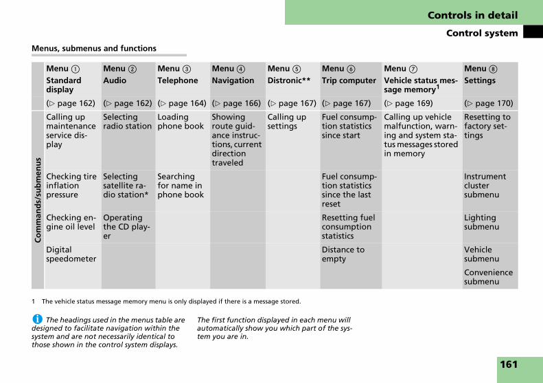
Controls in detail
Control system
Menus, submenus and functions
i The headings used in the menus table are designed to facilitate navigation within the system and are not necessarily identical to those shown in the control system displays.
The first function displayed in each menu will automatically show you which part of the sys-tem you are in.
Menu 1
Standard display
Menu 2
AudioMenu 3
TelephoneMenu 4
NavigationMenu 5
Distronic**Menu 6
Trip computerMenu 7
Vehicle status mes-sage memory1
1 The vehicle status message memory menu is only displayed if there is a message stored.
Menu 8
Settings
(� page 162) (� page 162) (� page 164) (� page 166) (� page 167) (� page 167) (� page 169) (� page 170)
Co
mm
and
s/su
bm
enu
s
Calling up maintenance service dis-play
Selecting radio station
Loading phone book
Showing route guid-ance instruc-tions, current direction traveled
Calling up settings
Fuel consump-tion statistics since start
Calling up vehicle malfunction, warn-ing and system sta-tus messages stored in memory
Resetting to factory set-tings
Checking tire inflation pressure
Selecting satellite ra-dio station*
Searching for name in phone book
Fuel consump-tion statistics since the last reset
Instrument cluster submenu
Checking en-gine oil level
Operating the CD play-er
Resetting fuel consumption statistics
Lighting submenu
Digital speedometer
Distance to empty
Vehicle submenu
Convenience submenu
161

Controls in detail
Control system
In basic mode, the multifunction display shows the trip odometer and the main odometer. This is known as the standard display.
1 Trip odometer2 Main odometer
In case you see another display:
� Press button è or ÿ repeatedly until the standard display appears.
� Press button k or j repeatedly to select the functions in the standard display menu.
The following functions are available:
Calling up digital speedometer
� Press button k or j repeatedly until the digital speedometer appears in the multifunction display.
The current vehicle speed is shown in the multifunction display.
Current vehicle speed
The functions in the AUDIO menu operate the audio equipment which you current-ly have turned on.
If no audio equipment is currently turned on, the message AUDIO OFF is shown in the multifunction display.
The following functions are available:
Standard display menu
Function Page
Calling up maintenance service display
339
Checking tire inflation pressure 321
Checking engine oil level 309
Calling up digital speedometer 162
Audio menu
Function Page
Selecting radio station 163
Selecting satellite radio station (USA only)
163
Operating the CD player 163
162

Controls in detail
Control system
Selecting radio station
� Turn on COMAND and select radio. Refer to the separate COMAND and Rear-Cabin Audiovisual System oper-ating instructions.
� Press button è or ÿ repeatedly until you see the currently tuned sta-tion in the multifunction display.
1 Waveband2 Station frequency
� Press button k or j repeatedly until the desired station is found.
i You can only store new stations using the corresponding feature on the radio. Refer to the separate COMAND and Rear-Cabin Audio-visual System operating instructions.
Selecting satellite radio channel (USA only)
The SIRIUS satellite radio is treated as a radio application.
� Turn on COMAND and select the cor-responding key on the COMAND control panel. Refer to the separate COMAND and Rear-Cabin Audiovisu-al System operating instructions.
� Press button è or ÿ repeatedly until you see the currently tuned channel in the multifunction display.
1 Channel name or number2 SAT mode and preset number
� Press button k or j repeatedly until the desired channel is found.
i A subscription to satellite radio service provider is required for satellite radio opera-tion. Contact an authorized Maybach Studio for details.
For more information, refer to the separate COMAND and Rear-Cabin Audiovisual System operating instructions.
Operating the CD player
� Turn on COMAND and select CD. Re-fer to the separate COMAND and Rear-Cabin Audiovisual System oper-ating instructions.
� Press button è or ÿ repeatedly until the settings for the CD currently being played are shown in the multi-function display.
1 Current track2 Indicates CD mode
� Press button k or j repeatedly until the desired track is selected.
i You can only choose a CD using COMAND. Refer to the separate COMAND and Rear-Cabin Audiovisual System operating instructions.
163

Controls in detail
Control system
Select MP3-CD track
� Turn on COMAND and select MP3-CD. Refer to the separate COMAND and Rear-Cabin Audiovisual System oper-ating instructions.
� Press button è or ÿ repeatedly until the settings for the MP3-CD cur-rently being played are shown in the multifunction display.
1 Current track2 Indicates MP3-CD mode
� Press button k or j repeatedly until the desired track is selected.
i Level of information displayed will vary depending on the information contained on the MP3-CD.
You can use the functions in the PHONE menu to operate your telephone, provid-ed it is connected to a hands-free system and switched on.
Logging-on to a network
� Switch on the telephone and COMAND.
� Press button ÿ or è on the steering wheel repeatedly until you see the PHONE menu in the multifunc-tion display.
Which messages will appear in the multi-function display depends on whether your telephone is switched on or off:
� If the telephone is off, the message in the multifunction display is: PLEASE TURN PHONE ON.
Telephone menu
Warning! G
A driver’s attention to the road and traffic conditions must always be his/her primary focus when driving. For your safety and the safety of others, we recommend that you pull over to a safe location and stop before making or taking a telephone call. If you choose to use the telephone while driving, please use the hands-free device and only use the telephone when weather, road and traffic conditions permit.
Some jurisdictions prohibit the driver from using a mobile telephone while driving a vehicle.
Bear in mind that at a speed of just 30 mph (approximately 50 km/h), your vehicle is covering a distance of 44 feet (approxi-mately 14 m) every second.
Warning! G
Never operate radio transmitters equipped with a built-in or attached antenna (i.e. without being connected to an external antenna) from inside the vehicle while the engine is running. Doing so could lead to a malfunction of the vehicle’s electronic sys-tem, possibly resulting in an accident and/or personal injury.
164
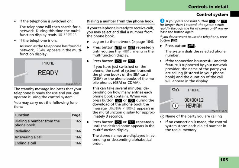
Controls in detail
Control system
� If the telephone is switched on:
The telephone will then search for a network. During this time the multi-function display reads NO SERVICE.
� If the telephone is on:
As soon as the telephone has found a network, READY appears in the multi-function display.
The standby message indicates that your telephone is ready for use and you can operate it using the control system.
You may carry out the following func-tions:
Dialing a number from the phone book
If your telephone is ready to receive calls, you may select and dial a number from the phone book.
� Log on to the network (� page 164).
� Press button ÿ or è repeatedly until you see the PHONE menu in the multifunction display.
� Press button j or k.
If you have just switched on the phone, the control system transmit the phone books of the SIM card (GSM) or the phone books of the mo-bile phones (GSM or CDMA).
This can take several minutes, de-pending on how many entries each phone book contains. When you press button j or k during the download of the phone book the message LOADING PHBOOK! appears in the multifunction display for approx-imately 3 seconds.
� Press button j or k repeatedly until the desired name appears in the multifunction display.
The stored names are displayed in as-cending or descending alphabetical order.
i If you press and hold button j or k for longer than 1 second, the system scrolls rapidly through the list of names until you re-lease the button again.
If you do not want to use the telephone, press button t.
� Press button s.
The system dials the selected phone number.
� If the connection is successful and this feature is supported by your network provider, the name of the party you are calling (if stored in your phone book) and the duration of the call will appear in the display.
1 Name of the party you are calling
� If no connection is made, the control system stores each dialed number in the redial memory.
Function Page
Dialing a number from the phone book
165
Redialing 166
Answering a call 166
Ending a call 166
165

Controls in detail
Control system
Redialing
The control system stores the most re-cently dialed phone numbers. This elimi-nates the need to search through your entire phone book.
� Press button ÿ or è repeatedly until you see the PHONE menu in the multifunction display.
� Press button s.
In the multifunction display you see the first number in the redial memo-ry.
� Press button j or k repeatedly until the desired name appears in the multifunction display.
i If you do not want to use the telephone, press button t.
� Press button s.
The control system dials the selected phone number.
Answering a call
When your telephone is ready to receive calls, you can answer a call at any time. In the multifunction display you will see the message, or if available, the caller ID (name and number):
i The caller’s number appears only if it is transmitted.
The caller’s name appears only if the number and the name are stored in the phone book.
� Press button s.
You have answered the call. In the multifunction display you see the length of the call positioned above the number.
Ending a call or reject an incoming call
� Press button t.
You have ended the call. In the multi-function display you will again see the standby message.
The NAV menu contains the functions needed to operate your navigation sys-tem.
� Press button è or ÿ repeatedly until you see NAV in the multifunction display.
� If COMAND is switched off, the mes-sage NAVI OFF is shown in the multi-function display.
� With COMAND switched on but route guidance not activated, the direction of travel and, if available, the name of the street currently traveled on ap-pear in the multifunction display.
� With COMAND switched on and route guidance activated, the direc-tion of travel and maneuver instruc-tions appear in the multifunction display.
Please refer to the separate COMAND and Rear-Cabin Audiovisual System man-ual for instructions on how to activate the route guidance system.
Navigation menu
166

Controls in detail
Control system
Use the DISTRONIC menu to display the current settings for your Distronic sys-tem. What information is shown in the multifunction display depends on whether the Distronic system is active or inactive.
Please refer to the “Driving systems” sec-tion of this manual (� page 223) for in-structions on how to activate Distronic.
� Press button è or ÿ repeatedly until you see one of the following two pictures in the multifunction dis-play.
Distronic deactivated
When Distronic is deactivated, you will see the standard display.
1 Vehicle ahead, if detected2 Actual distance to vehicle ahead3 Preset distance threshold to vehicle
ahead4 Your vehicle5 Symbol for activated distance warn-
ing function
Distronic activated
When you activate Distronic, you will see the set speed for about 5 seconds in the Distronic display. The following display then appears:
1 Distronic activated
Use the trip computer menu to call up statistical data on your vehicle. The fol-lowing information is available:
Distronic** menu
Trip computer menu
Function Page
Fuel consumption statistics since start
168
Fuel consumption statistics since last reset
168
Resetting fuel consumption statistics
168
Distance to empty 168
167

Controls in detail
Control system
Fuel consumption statistics since start
� Press button ÿ or è repeatedly until you see the first function of the trip computer menu.
� Press button j or k repeatedly until the message FROM START ap-pears in the multifunction display.
i Each time you call up the trip computer, the last function used appears as the first dis-play.
1 Distance driven since start2 Time elapsed since start3 Average fuel consumption since start4 Average speed since start
Incorporating statistics from the previ-ous journey in the consumption statis-tics
When you restart the engine, the FROM START display flashes for:
� a distance of approximately 1.25 miles (2 kilometers)
or
� a duration of 2 minutes
During this period, the data from the previous journey can be incorporated as follows:
� Press reset button J (� page 154) in the instrument cluster.
The statistics will be incorporated.
i If you do not press reset button J, the consumption statistics will be reset to 0.
Fuel consumption since last reset
� Press button ÿ or è repeatedly until you see the first function of the trip computer menu.
� Press button j or k repeatedly until the message SINCE RESET ap-pears in the multifunction display.
1 Distance driven since last reset2 Time elapsed since last reset3 Average fuel consumption since last
reset4 Average speed since last reset
Resetting fuel consumption statistics
� Press button ÿ or è repeatedly until you see the first function of the trip computer menu.
� Press button j or k repeatedly until you see the reading that you want to reset in the multifunction display.
� Press and hold reset button J (� page 154) in the instrument clus-ter until the value is reset to 0.
Distance to empty
� Press button ÿ or è repeatedly until you see the first function of the trip computer menu.
� Press button j or k repeatedly until the message RANGE appears in the multifunction display.
The calculated remaining driving range based on the current fuel tank level appears in the multifunction dis-play.
168

Controls in detail
Control system
Use the vehicle status message memory menu to scan malfunction and warning messages that may be stored in the sys-tem. Such messages appear in the multi-function display and are based on conditions or system status the vehicle’s system has recorded.
The vehicle status message memory menu only appears if there are any mes-sages stored.
� Press button è or ÿ repeatedly until the vehicle status message mem-ory appears in the multifunction dis-play.
If the vehicle status message memory menu does not appear, then there are no messages stored.
Vehicle status messages have been re-corded
If conditions have occurred causing sta-tus messages to be recorded, the number of messages appears in the multifunction display:
1 Number of messages
� Press button k or j.
The stored messages will now be dis-played in order. See the “Practical hints” section for malfunction and warning messages (� page 364).
i The vehicle status message memory will be cleared when you switch off the ignition. You will then only see high-priority messages in the multifunction display. These are high-lighted in red color (� page 364).
Vehicle status message memory menu
Warning! G
Malfunction and warning messages are only indicated for certain systems and are intentionally not very detailed. The mal-function and warning messages are simply a reminder with respect to the operation of certain systems and do not replace the owner’s and/or driver’s responsibility to maintain the vehicle’s operating safety by having all required maintenance and safe-ty checks performed on the vehicle and by bringing the vehicle to an authorized Maybach Studio to address the malfunc-tion and warning messages (� page 364).
169

Controls in detail
Control system
In the SETTINGS menu there are two functions:
� The function TO RESET PRESS R BUTTON FOR 3 SEC., with which you can reset all the settings to the original factory settings.
� A collection of submenus with which you can make individual settings for your vehicle.
� Press button è or ÿ repeatedly until the message SETTINGS appears in the multifunction display.
Resetting all settings
You can reset all the functions of all sub-menus to the factory settings.
� Press reset button J (� page 154) in the instrument cluster for approxi-mately 3 seconds.
In the display you will see the request to press reset button J again to con-firm.
� Press reset button J again.
The functions of all the submenus will reset to factory settings.
i The settings you have changed will not be reset unless you confirm the action by press-ing reset button J a second time. After ap-proximately 5 seconds, the SETTINGS menu appears again.
Due to safety reasons, resetting all of the set-tings while driving will not reset all of the val-ues in the LIGHTING or the VEHICLE submenu.
Submenus in the Settings menu
� Press button j.
The various submenus appear in the multifunction display.
� Press button æ or ç.
The selection marker moves to the next submenu.
The submenus are arranged by hierar-chy. Scroll down with button ç, scroll up with button æ.
With the selection marker on the desired submenu, use button j to access the individual functions within that sub-menu. Once within the submenu, you can use button j to move to the next function or button k to move to the previous function within that submenu.
The settings themselves are made with button æ or ç.
Settings menu Function Page
Resetting all settings 170
Submenus in the Settings menu 170
Instrument cluster submenu 172
Lighting submenu 172
Vehicle submenu 176
Convenience submenu 177
170

Controls in detail
Control system
The table below shows what settings can be changed within the various menus. Detailed instructions on making individ-ual settings can be found on the follow-ing pages.
INSTRUMENT CLUSTER
(� page 172)
LIGHTING
(� page 172)
VEHICLE
(� page 176)
CONVENIENCE
(� page 177)
Selecting speedometer display mode
Setting daytime running lamp mode (USA only)
Setting automatic locking Activating easy-entry/exit feature
Selecting language Setting locator lighting Setting station selection mode Setting fold-in function for ex-terior rear view mirrors
Setting ambient lighting
Setting night security illumina-tion
Setting interior lighting de-layed switch-off
171

Controls in detail
Control system
Instrument cluster submenu
Access the INST. CLUS. submenu via the SETTINGS menu. Use the INST. CLUS. submenu to change the instrument clus-ter display settings. The following func-tions are available:
Selecting speedometer display mode
� Move the selection marker with button æ or ç to the INST. CLUS. submenu.
� Press button j or k repeatedly until the message DISPLAY VALUES IN appears in the multifunction display.
The selection marker is on the current setting.
� Press button æ or ç to set speedometer unit to MILES or KM.
Selecting language
� Move the selection marker with button æ or ç to the INST. CLUS. submenu.
� Press button j or k repeatedly until the message LANGUAGE appears in the multifunction display.
The selection marker is on the current setting.
� Press button æ or ç to select the language to be used for the mul-tifunction display messages.
Available languages:
� German
� English
� French
� Italian
� Spanish
Lighting submenu
Access the LIGHTING submenu via the SETTINGS menu. Use the LIGHTING sub-menu to change the lamp and lighting settings on your vehicle. The following functions are available:
Function Page
Selecting speedometer display mode
172
Selecting language 172
Function Page
Setting daytime running lamp mode (USA only)
173
Setting locator lighting 173
Setting ambient lighting 174
Setting night security illumina-tion
174
Setting interior lighting delayed shut-off
175
172

Controls in detail
Control system
Setting daytime running lamp mode (USA only)
i This function is not available in countries where the daytime running lamp mode is mandatory and therefore in a constant mode.
� Move the selection marker with button æ or ç to the LIGHTING submenu.
� Press button j or k repeatedly until the message LIGHTING CIRCUIT HEADLAMP MODE appears in the multi-function display.
The selection marker is on the current setting.
� Press button æ or ç to select manual operation (MANUAL)or daytime running lamp mode (CONSTANT).
With daytime running lamp mode acti-vated and the exterior lamp switch at po-sition M or U, the low beam headlamps are switched on when the en-gine is running.
In low ambient light conditions the fol-lowing lamps will switch on additionally:
� Parking lamps
� Tail lamps
� License plate lamps
� Side marker lamps
For more information on the daytime running lamp mode, see “Lighting” (� page 144).
i For safety reasons, resetting the LIGHTING submenu to factory settings (� page 170) while driving will not deactivated the daytime running lamp mode.
The following message appears in the multi-function display:
LIGHTING CANNOT BE COMPLETELY RESET TO FACTORY SETTINGS WHILE DRIVING.
Setting locator lighting
With the locator lighting feature activat-ed and the exterior lamp switch in position U, the following lamps will switch on during darkness when the ve-hicle is unlocked using button ‹ on the SmartKey or SmartKey with KEYLESS-GO**:
� Parking lamps
� Tail lamps
� License plate lamps
� Side marker lamps
� Front fog lamps
� Exterior rear view mirror lamps
The locator lighting switches off when the driver’s door is opened.
If you do not open a door after unlock-ing the vehicle with the SmartKey, the lamps will switch off automatically after approximately 40 seconds.
� Move the selection marker with button æ or ç to the LIGHTING submenu. ��
173
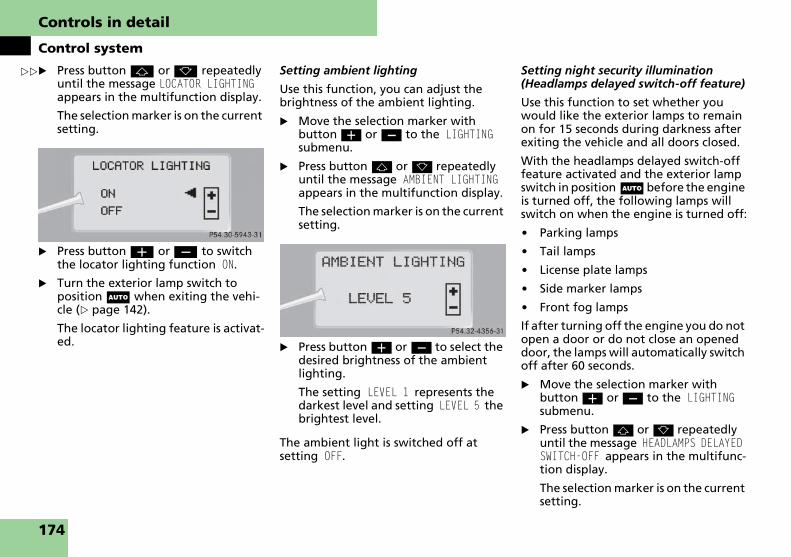
Controls in detail
Control system
�
� Press button j or k repeatedly until the message LOCATOR LIGHTING appears in the multifunction display.The selection marker is on the current setting.
� Press button æ or ç to switch the locator lighting function ON.
� Turn the exterior lamp switch to position U when exiting the vehi-cle (� page 142).
The locator lighting feature is activat-ed.
Setting ambient lighting
Use this function, you can adjust the brightness of the ambient lighting.
� Move the selection marker with button æ or ç to the LIGHTING submenu.
� Press button j or k repeatedly until the message AMBIENT LIGHTING appears in the multifunction display.
The selection marker is on the current setting.
� Press button æ or ç to select the desired brightness of the ambient lighting.
The setting LEVEL 1 represents the darkest level and setting LEVEL 5 the brightest level.
The ambient light is switched off at setting OFF.
Setting night security illumination (Headlamps delayed switch-off feature)
Use this function to set whether you would like the exterior lamps to remain on for 15 seconds during darkness after exiting the vehicle and all doors closed.
With the headlamps delayed switch-off feature activated and the exterior lamp switch in position U before the engine is turned off, the following lamps will switch on when the engine is turned off:
� Parking lamps
� Tail lamps
� License plate lamps
� Side marker lamps
� Front fog lamps
If after turning off the engine you do not open a door or do not close an opened door, the lamps will automatically switch off after 60 seconds.
� Move the selection marker with button æ or ç to the LIGHTING submenu.
� Press button j or k repeatedly until the message HEADLAMPS DELAYED SWITCH-OFF appears in the multifunc-tion display.
The selection marker is on the current setting.
�
174

Controls in detail
Control system
� Press button æ or ç to switch the headlamps delayed switch-off feature ON or OFF.
� Turn the exterior lamp switch to position U before turning off the engine (� page 142).
The headlamps delayed switch-off feature is activated.
You can temporarily deactivate the headlamps delayed switch-off feature:
� Before exiting the vehicle, turn the SmartKey in the starter switch to position 0.
� Then turn the SmartKey in the starter switch to position 2 and back to 0.
The headlamps delayed switch-off feature is deactivated. It will reacti-vate as soon as you reinsert the SmartKey in the starter switch.
Vehicles with KEYLESS-GO**:
� Press the KEYLESS-GO start/stop but-ton on the gear selector lever (� page 61).
Setting interior lighting delayed switch-off
Use this function to set whether you would like the interior lighting to remain on for 10 seconds during darkness after you have removed the SmartKey from the starter switch.
� Move the selection marker with button æ or ç to the LIGHTING submenu.
� Press button j or k repeatedly until the message INTERIOR LIGHTING DELAYED SWITCH-OFF appears in the multifunction display.
The selection marker is on the current setting.
� Press button æ or ç to switch the interior lighting delayed switch-off feature ON or OFF.
175

Controls in detail
Control system
Vehicle submenu
Access the VEHICLE submenu via the SET-TINGS menu. Use the VEHICLE submenu to make general vehicle settings. The following functions are available:
Setting automatic locking
Use this function to activate or deacti-vate the automatic central locking. With the automatic central locking system ac-tivated, the vehicle is centrally locked at vehicle speeds of approximately 9 mph (15 km/h).
� Move the selection marker with button æ or ç to the VEHICLE submenu.
� Press button j or k repeatedly until the message AUTOMATIC DOOR LOCK appears in the multifunction dis-play.
The selection marker is on the current setting.
� Press button æ or ç to switch AUTOMATIC DOOR LOCK ON or OFF.
Setting station selection mode
Use the STATION SEARCH USING function to select the manual or memory station selection mode for the radio (� page 163).
� Move the selection marker with button æ or ç to the VEHICLE submenu.
� Press button j or k repeatedly until the message STATION SEARCH USING. appears in the multifunction display.
The selection marker is on the current setting.
� Press button æ or ç to select the desired station selection mode. You can select:
� FREQUENCY
� MEMORY selects next stored station
Function Page
Setting automatic locking 176
Setting station selection mode 176
176
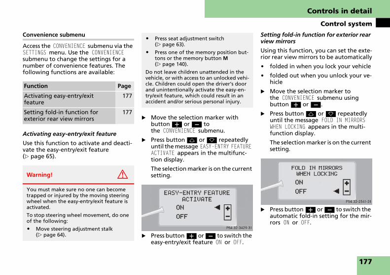
Controls in detail
Control system
Convenience submenu
Access the CONVENIENCE submenu via the SETTINGS menu. Use the CONVENIENCE submenu to change the settings for a number of convenience features. The following functions are available:
Activating easy-entry/exit feature
Use this function to activate and deacti-vate the easy-entry/exit feature (� page 65).
� Move the selection marker with button æ or ç to the CONVENIENCE submenu.
� Press button j or k repeatedly until the message EASY-ENTRY FEATURE ACTIVATE appears in the multifunc-tion display.
The selection marker is on the current setting.
� Press button æ or ç to switch the easy-entry/exit feature ON or OFF.
Setting fold-in function for exterior rear view mirrors
Using this function, you can set the exte-rior rear view mirrors to be automatically
� folded in when you lock your vehicle
� folded out when you unlock your ve-hicle
� Move the selection marker to the CONVENIENCE submenu using button æ or ç.
� Press button j or k repeatedly until the message FOLD IN MIRRORS WHEN LOCKING appears in the multi-function display.
The selection marker is on the current setting.
� Press button æ or ç to switch the automatic fold-in setting for the mir-rors ON or OFF.
Function Page
Activating easy-entry/exit feature
177
Setting fold-in function for exterior rear view mirrors
177
Warning! G
You must make sure no one can become trapped or injured by the moving steering wheel when the easy-entry/exit feature is activated.
To stop steering wheel movement, do one of the following:
� Move steering adjustment stalk (� page 64).
� Press seat adjustment switch (� page 63).
� Press one of the memory position but-tons or the memory button M (� page 140).
Do not leave children unattended in the vehicle, or with access to an unlocked vehi-cle. Children could open the driver’s door and unintentionally activate the easy-en-try/exit feature, which could result in an accident and/or serious personal injury.
177

Controls in detail
Automatic transmission
For more information on driving with an automatic transmission see “Automatic transmission” (� page 70).
Your vehicle’s transmission adapts its gear shifting process to your individual driving style by continually adjusting the shift points up or down. These shift point adjustments are performed based on current operating and driving condi-tions.
If the operating conditions change, the automatic transmission reacts by adjust-ing its shift program.
i During the brief warm-up, the transmis-sion upshifting is delayed. This allows the catalytic converter to heat up more quickly to operating temperature.
The gear selector lever is located on the lower part of the front center console.
Gearshift pattern for automatic transmission
P Park position
R Reverse gear
N Neutral
D Drive position
i The current gear selector lever position P, R, N or D appears in the tachometer display (� page 180).
Automatic transmissionWarning! G
Make sure that absolutely no objects are obstructing the pedals’ range of move-ment. Keep the driver’s footwell clear of all obstacles. If there are any floormats or carpets in the footwell, make sure that the pedals still have sufficient clearance.
During sudden driving or braking maneu-vers the objects could get caught between the pedals. You could then no longer brake or accelerate. This could lead to acci-dents and injury.
Gear selector lever
178

Controls in detail
Automatic transmission
The automatic transmission selects indi-vidual gears automatically, depending on:
� the gear selector lever position D (� page 180) with gear ranges (� page 182)
� the selected program mode (C/S) (� page 183)
� the position of the accelerator pedal (� page 181)
� the vehicle speed
! Allow engine to warm up under low load use. Do not place full load on the engine until the operating temperature has been reached.
Shift into reverse gear R or park position P only when the vehicle is stopped.
Avoid spinning of a drive wheel for an extended period when driving off on slippery road surfaces. This may cause serious damage to the drivetrain which is not covered by the Maybach Limited Warranty.
When the gear selector lever is in position D, you can influence transmis-sion shifting by:
� limiting the gear range
� changing gears manually
Warning! G
It is dangerous to shift the gear selector lever out of park position P or neutral position N if the engine speed is higher than idle speed. If your foot is not firmly on the brake pedal, the vehicle could acceler-ate quickly forward or reverse. You could lose control of the vehicle and hit someone or something. Only shift into gear when the engine is idling normally and when your right foot is firmly on the brake pedal.
Shifting procedure
179

Controls in detail
Automatic transmission
The current gear selector lever position appears in the tachometer display.
1 Current gear selector lever position
! Coasting the vehicle, or driving for any other reason with gear selector lever in neutral position N can result in transmission damage that is not covered by the Maybach Limited Warranty.
Gear selector lever positions Effect
ì Park position
Gear selector lever position when the vehicle is parked. Place gear selector lever in park position P only when vehicle is stopped. The park position is not intended to serve as a brake when the vehicle is parked. Rather, the driver should always set the parking brake in addition to placing the gear selector lever in park position P to secure the vehicle.
The SmartKey can only be removed from the starter switch with the gear selector lever in park position P. With the SmartKey removed, the gear selector lever is locked in park position P.
í Reverse gear
Place gear selector lever in position R only when vehicle is stopped.
Effect
ë Neutral
No power is transmitted from the engine to the drive axle. When the brakes are released, the vehicle can be moved freely (pushed or towed).
To avoid damage to the trans-mission, never engage neutral position N while driving.
If the ESP® is deactivated or malfunctioning:Move gear selector lever to neutral position N only if the vehicle is in danger of skid-ding, e.g. on icy roads.
ê Drive
The transmission shifts auto-matically. All forward gears are available.
180

Controls in detail
Automatic transmission
Accelerator position
Your driving style influences the transmission’s shifting behavior:
Less throttle Earlier upshifting
More throttle Later upshifting
Kickdown
Use kickdown when you want maximum acceleration.
� Press the accelerator past the point of resistance.
Depending on the engine speed the transmission shifts into a lower gear.
� Ease on the accelerator when you have reached the desired speed.
The transmission shifts up again.
Stopping
When you stop briefly, e.g. at traffic lights:
� Leave the transmission in gear.
� Hold the vehicle with the brake.
When you stop for a longer period of time with the engine idling and/or on a hill:
� Set the parking brake.
� Move gear selector lever to park position P.
Warning! G
Getting out of your vehicle with the gear selector lever not fully engaged in park position P is dangerous. Also, park position P alone is not intended to or capable of preventing your vehicle from moving, possibly hitting people or objects.
Always set the parking brake in addition to shifting to park position P (� page 72).
When parked on an incline, turn the front wheels towards the road curb.
Do not park this vehicle in areas where combustible materials such as grass, hay or leaves can come into contact with the hot exhaust system, as these materials could be ignited and cause a vehicle fire.
Warning! G
When leaving the vehicle, always remove the SmartKey or SmartKey with KEYLESS-GO** from the starter switch, take it with you, and lock the vehicle. Do not leave children unattended in the vehi-cle, or with access to an unlocked vehicle. Children could move the gear selector lever from park position P, which could result in an accident and/or serious personal injury.
Driving tips
181

Controls in detail
Automatic transmission
Maneuvering
When you maneuver in tight areas, e.g. when pulling into a parking space:
� Control the vehicle speed by gradually releasing the brakes.
� Accelerate gently.
� Never abruptly step on the accelera-tor.
Working on the vehicle
With the gear selector lever in drive position D, you can select a gear range for the automatic transmission to operate within.
You can limit the gear range by pressing the gear selector lever to the left (D-), and reverse the gear range limit by pressing the gear selector lever to the right (D+) (� page 184).
The selected gear range appears in the tachometer display.
1 Current gear range
Warning! G
When working on the vehicle, set the park-ing brake and move gear selector lever to park position P. Otherwise the vehicle could roll away.
Gear ranges Effect
é The transmission shifts through fourth gear only.
è The transmission shifts through third gear only.
With this selection you can use the braking effect of the en-gine.
ç The transmission shifts through second gear only.
Allows the use of engine’s braking power when driving
� on steep downgrades
� in mountainous regions
� under extreme operating conditions
æ The transmission operates in first gear only.
For maximum use of engine’s braking effect on very steep or lengthy downgrades.
182

Controls in detail
Automatic transmission
The program mode selector switch is located on the lower part of the front center console.
Program mode selector switch
C Comfort For comfort driving
S Sport For standard driving
The selected program mode appears in the tachometer display.
1 Current program mode
! Never change the program mode when the gear selector lever is out of park position P. This could result in a change of driving characteristics for which you may not be prepared.
i The last selected program mode (C or S) is switched on when the engine is restarted.
� Press program mode selector switch repeatedly until the letter of the desired program mode appears in the tachometer display.
Select C for comfort driving:
� Traction and driving stability are improved on icy roads.
� Upshifts occur earlier even when you give more gas. The engine then operates at lower rpms and the wheels are less likely to spin.
Select S for standard driving:
� Upshifts occur earlier.
Automatic shift program
183

Controls in detail
Automatic transmission
With the gear selector lever in drive position D, you can limit or extend the gear range.
! Allow engine to warm up under low load use. Do not place full load on the engine until the operating temperature has been reached.
Shift into reverse gear R or park position P only when the vehicle is stopped.
Avoid spinning of a drive wheel for an extended period when driving off on slippery road surfaces. This may cause serious damage to the drivetrain which is not covered by the Maybach Limited Warranty.
Limiting gear range
� Briefly press the gear selector lever to the left in the D– direction.
The transmission will shift to the next lower gear as permitted by the shift program. This action simultaneously limits the gear range of the transmis-sion (� page 180).
i To avoid overrevving the engine when downshifting, the transmission will not shift to a lower gear if the engine’s max. speed would be exceeded.
Extending gear range
� Briefly press the gear selector lever to the right in the D+ direction.
The transmission will shift to the next higher gear as permitted by the shift program. This action simultaneously extends the gear range of the trans-mission.
i If you press on the accelerator when the engine has reached its rpm limit, the transmis-sion will upshift beyond any gear range limit selected.
Canceling gear range limit
� Press and hold the gear selector lever in the D+ direction until D reappears in the tachometer display (� page 180).
The transmission will shift from the current gear range directly to gear range D.
Shifting into optimal gear range
� Press and hold the gear selector lever in the D– direction.
The transmission will automatically select the gear range suited for opti-mal acceleration and deceleration. This will involve shifting down one or more gears.
One-touch gearshifting
Warning! G
On slippery road surfaces, never downshift in order to obtain braking action. This could result in drive wheel slip and reduced vehicle control. Your vehicle’s ABS will not prevent this type of loss of control.
184
Controls in detail
Automatic transmission
If vehicle acceleration becomes less re-sponsive or sluggish or the transmission no longer shifts, the transmission is most likely operating in limp-home (emergency operation) mode. In this mode only second gear and reverse gear can be selected.
� Stop the vehicle in a safe location.
� Move the gear selector lever to park position P.
� Turn off the engine.
� Wait at least 10 seconds before restarting.
� Restart the engine.
� Move the gear selector lever to position D (for second gear) or position R.
� Have the transmission checked at an authorized Maybach Studio as soon as possible.
Emergency operation (Limp-Home Mode)
185

Controls in detail
Good visibility
For information on the windshield wip-ers, see “Windshield wipers” (� page 74).
The button is located on the left side of the dashboard.
1 Headlamp washer button
� Switch on the ignition (� page 60).
� Press button 1.
The headlamps are cleaned with a high-pressure water jet.
i The headlamps will automatically be cleaned when you have
� switched on the headlamps
and
� operated the windshield wipers with windshield washer fluid fifteen times
When you switch off the ignition, the counter resets.
For information on filling up the washer reservoir, see “Windshield washer sys-tem and headlamp cleaning system” (� page 446).
For information on setting the rear view mirrors, see “Mirrors” (� page 66).
Auto-dimming rear view mirrors
The reflection brightness of the exterior rear view mirror on the driver’s side and the interior rear view mirror will respond automatically to glare when
� the auto-dimming function is activat-ed (� page 187)
� the ignition is switched on
and
� incoming light from headlamps falls on the sensor in the interior rear view mirror
The rear view mirror will not react if
� reverse gear is engaged
� the interior lighting is turned on
Good visibility
Headlamp cleaning system
Rear view mirrors
Warning! G
The auto-dimming function does not react if incoming light is not aimed directly at sensors in the interior rear view mirror.
The interior rear view mirror and the exte-rior rear view mirror on the driver’s side do not react, for example, if the rear window curtain is closed.
Light hitting the mirror(s) at certain angles (incident light) could blind you. As a result, you may not be able to observe traffic con-ditions and could cause an accident.
Warning! G
In case of an accident, liquid electrolyte may escape from the mirror housing if the mirror glass breaks.
Electrolyte has an irritating effect. Do not allow the liquid to come into contact with eyes, skin, clothing, or respiratory system. In case it does, immediately flush affected area with water, and seek medical help if necessary.
186

Controls in detail
Good visibility
! Electrolyte drops coming into contact with the vehicle paint finish can be completely removed only while in the liquid state by ap-plying plenty of water.
Deactivating
� Switch on the ignition (� page 60).
� Press button 1.
The green indicator lamp in button 1 goes out.
Activating
� Press button 1 again.
The green indicator lamp in button 1 comes on.
i The setting will remain stored even when you remove the SmartKey from the starter switch.
Activating exterior rear view mirror parking position
Follow these steps to activate the mirror parking position so that the passenger-side exterior rear view mirror will be turned downward to the stored position.
The buttons are located on the driver’s door.
1 Driver’s side exterior rear view mirror2 Passenger-side exterior rear view
mirror
Warning! G
Exercise care when using the passenger-side exterior rear view mirror. The mirror surface is convex (outwardly curved sur-face for a wider field of view). Objects in mirror are closer than they appear. Check your interior rear view mirror or glance over your shoulder before changing lanes.
��
187
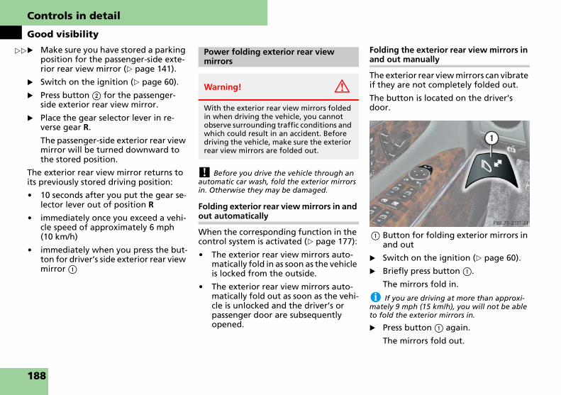
Controls in detail
Good visibility
�
� Make sure you have stored a parking position for the passenger-side exte-rior rear view mirror (� page 141).� Switch on the ignition (� page 60).
� Press button 2 for the passenger-side exterior rear view mirror.
� Place the gear selector lever in re-verse gear R.
The passenger-side exterior rear view mirror will be turned downward to the stored position.
The exterior rear view mirror returns to its previously stored driving position:
� 10 seconds after you put the gear se-lector lever out of position R
� immediately once you exceed a vehi-cle speed of approximately 6 mph (10 km/h)
� immediately when you press the but-ton for driver’s side exterior rear view mirror 1
! Before you drive the vehicle through an automatic car wash, fold the exterior mirrors in. Otherwise they may be damaged.
Folding exterior rear view mirrors in and out automatically
When the corresponding function in the control system is activated (� page 177):
� The exterior rear view mirrors auto-matically fold in as soon as the vehicle is locked from the outside.
� The exterior rear view mirrors auto-matically fold out as soon as the vehi-cle is unlocked and the driver’s or passenger door are subsequently opened.
Folding the exterior rear view mirrors in and out manually
The exterior rear view mirrors can vibrate if they are not completely folded out.
The button is located on the driver’s door.
1 Button for folding exterior mirrors in and out
� Switch on the ignition (� page 60).
� Briefly press button 1.
The mirrors fold in.
i If you are driving at more than approxi-mately 9 mph (15 km/h), you will not be able to fold the exterior mirrors in.
� Press button 1 again.
The mirrors fold out.
� Power folding exterior rear view mirrors
Warning! G
With the exterior rear view mirrors folded in when driving the vehicle, you cannot observe surrounding traffic conditions and which could result in an accident. Before driving the vehicle, make sure the exterior rear view mirrors are folded out.
188

Controls in detail
Good visibility
! If an exterior mirror housing is forcibly pushed forward (hit from the rear), reposition it manually by applying firm pressure until it snaps back into place.
If an exterior mirror is forcibly pushed rear-ward (hit from the front) press button 1 to fold mirrors in, then press button 1 to fold mirrors out. Do not force mirror by hand as it may damage the adjustment mechanism.
The mirror housing is now properly positioned and you can adjust the mirror normally.
The sun visors protect you from sun glare while driving.
i For information on vanity mirrors (� page 248).
Glare from the front
1 Sun visor
� Swing sun visor 1 down.
Glare from the front and sides
! Close the vanity mirror cover (if open) be-fore you disengage sun visor 1 from mounting 2 and pivot it to the side.
1 Sun visor2 Mounting3 Additional sun visor
� Swing sun visor 1 down.
� Disengage sun visor 1 from mounting 2.
� Pivot sun visor to the side.
The sun visors are extendable.
� Adjust the sun visors by pushing or pulling in direction of the arrows.
� Swing additional sun visor 3 down.
Sun visors
Warning! G
Do not use the vanity mirror while driving.
Keep the mirrors in the sun visors closed while the vehicle is in motion. Reflected glare can endanger you and others.
189

Controls in detail
Good visibility
The rear window defroster consumes high levels of energy. To keep battery drain to a minimum, switch off the de-froster as soon as the rear window is clear. The heating time varies depending on outside temperature and driving con-ditions, ranging from approximately 6 minutes at temperatures above 43°F (6°C) to over 20 minutes at temperatures below -14°F (-26°C) and at high speed.
� Switch on the ignition (� page 60).
Activating
� Press button F (� page 193).
The indicator lamp on the button comes on.
Deactivating
� Press button F again.
The indicator lamp on the button goes out.
i If the indicator lamp F is flashing, there is insufficient voltage due to too many electrical consumers are turned on. The rear window defroster switches off automatically.
The rear window defroster will switch back on again automatically as soon as sufficient volt-age is available.
Rear window defroster
Warning! G
Any accumulation of snow and ice should be removed from the rear window before driving. Visibility could otherwise be im-paired, endangering you and others.
190

Controls in detail
Automatic climate control
The automatic climate control is a 4-zone intelligent climate control system. Your vehicle interior is divided into four zones.
With the help of a sun sensor, the auto-matic climate control determines the re-lation of the sun to the vehicle and automatically adjusts the inside temper-ature for every individual zone.
The automatic climate control is opera-tional whenever the engine is running. It cools the vehicle’s interior according to the angle and intensity of the sun’s rays, the outside temperature and the select-ed temperature.
i Condensation may drip from underneath the vehicle. This is normal and not an indica-tion of a malfunction.
The activated charcoal filter, when switched on, markedly reduces odors and removes pollutants from the air en-tering the passenger compartment.
Nearly all dust particles, pollutants and odors are filtered out before outside air enters the passenger compartment through the air distribution system.
The air conditioning will not engage (no cooling) if the air conditioning mode is deactivated (� page 200).
i Severe conditions (e.g. strong air pollu-tion) may require replacement of the filter be-fore its scheduled interval. A clogged filter will reduce the air volume to the interior.
If the vehicle interior is hot, ventilate the inte-rior before driving off, see “Summer opening feature” (� page 211). The automatic climate control will then adjust the interior tempera-ture to the set value much faster.
Keep the air intake grille in front of the wind-shield free of snow, leaves, sticks and any oth-er debris.
Do not obstruct air volume by placing objects on the air flow-through exhaust slots below the rear window.
Automatic climate control
Warning! G
When operating the automatic climate control, the air that enters the passenger compartment through the air vents can be very hot or very cold (depending on the set temperature). This may cause burns or frostbite to unprotected skin in the imme-diate area of the air vents. Always keep sufficient distance between unprotected parts of the body and the air vents. If nec-essary, use the air distribution control (� page 193) to direct the air to air vents in the vehicle interior that are not in the im-mediate area of unprotected skin.
Warning! G
Follow the recommended settings for heating and cooling given on the follow-ing pages. Otherwise the windows could fog up, impairing visibility and endanger-ing you and others.
191

Controls in detail
Automatic climate control
Cockpit
1 Left side air vent, adjustable
2 Left center air vent, adjustable
3 Fixed air vent
4 Right center air vent, adjustable
5 Right side air vent, adjustable
6 Thumbwheel for air volume con-trol for right side air vent
7 Thumbwheel for air volume con-trol for right center air vent
8 Automatic climate control panel
9 Thumbwheel for air volume con-trol for left center air vent
a Thumbwheel for air volume con-trol for left side air vent
192

Controls in detail
Automatic climate control
Automatic climate control panel, front
1 Air distribution and air volume, driver’s side (automatic)
2 Air distribution, driver’s side (manual)
3 Air volume, driver’s side
4 Temperature control, driver’s side
5 Display
6 Temperature control, passenger side
7 Air volume, passenger side
8 Air distribution, passenger side (manual)
9 Air distribution and air volume, passenger side (automatic)
a Rear window defroster
b Rear air-conditioning remote control
c Automatic climate control on/off button
d AC cooling on/off
e Residual heat and ventilation
f Activated charcoal filter
g Air recirculation
h Front defroster
193

Controls in detail
Automatic climate control
It is possible to completely deactivate the automatic climate control system.
Deactivating
� Press button M (� page 193).
Reactivating
� Switch on the ignition (� page 60).
� Press button M or U (� page 193).
i When operating the climate control sys-tem in automatic mode, you will only rarely need to adjust the temperature, air volume and air distribution.
In automatic mode, cooling with dehumidify is switched on. This function can be switched off, if necessary.
i You can switch the automatic climate control system on and off for each side of the passenger compartment as desired.
Activating
� Switch on the ignition (� page 60).
� Press one button U (� page 193).
The indicator lamp on the button comes on. The air volume and air dis-tribution are adjusted automatically.
� Use temperature controls 4 for the left side or 6 (� page 193) for the right side to separately adjust the air temperature on each side of the pas-senger compartment.
The temperature of the vehicle interi-or is adjusted automatically.
Deactivating
� Press one button U (� page 193).
The indicator lamp on the button goes out. The automatic operation of air volume and air distribution switches off.
Deactivating the climate control sys-tem
Warning! G
When the automatic climate control is switched off, the outside air supply and cir-culation are also switched off. Only choose this setting for a short time. Otherwise the windows could fog up, impairing visibility and endangering you and others.
Operating the climate control system in automatic mode
Warning! G
If you switch off the cooling function the windows can fog up more quickly. Window fogging may impair visibility and endanger you and others.
194

Controls in detail
Automatic climate control
Use temperature controls 4 for the driver’s side or 6 (� page 193) for the passenger side to separately adjust the air temperature on each side of the pas-senger compartment. You should raise or lower the temperature setting in small increments, preferably starting at 72°F (22°C).
Increasing
� Push top of temperature control 4 and/or 6 until the display shows the desired temperature.
The automatic climate control system will adjust the interior air tempera-ture accordingly.
Decreasing
� Push bottom of temperature control 4 and/or 6 until the display shows the desired temperature.
The automatic climate control system will adjust the interior air tempera-ture accordingly.
Use the air distribution controls 2 and 8 (� page 193) to separately adjust the air distribution on each side of the passenger compartment. The following symbols are located on the controls:
� Press air distribution control 2 for the driver’s side and/or 8 for the passenger side (� page 193).
The indicator lamp on button U goes out.
The air volume is controlled automat-ically while the air distribution is con-trolled manually in the respective zone.
The selected air distribution is shown in the display 5 (� page 193).
Seven blower speeds are available.
� Press � to decrease or Q to in-crease air volume to the desired level.
The indicator lamp on button U goes out.
The air volume is controlled manually while the air distribution is controlled automatically in the respective zone.
The selected blower speed is shown in the display 5 (� page 193).
You can use this setting to defrost the windshield, for example if it is iced up. You can also defog the windshield and the side windows.
i Keep this setting selected only until the windshield or the side windows are clear again.
Activating
� Press button P (� page 193).
The indicator lamp on the button comes on.
Setting the temperature Adjusting air distribution
Symbol Function
Ô Directs air to the windows
Ø Directs air to the windows, footwells, center and side air vents
Ó Directs air to the footwell air vents
Õ Directs air to the center and side air vents
Adjusting air volume
Front defroster
��
195

Controls in detail
Automatic climate control
�
The automatic climate control switches automatically to the following functions:� maximum blowing and heating power (depends on cooling tem-perature)
� air flows onto the windshield and the front side windows
� cooling on to dehumidify
� the air recirculation mode is switched off
Deactivating
� Press button P (� page 193).
The indicator lamp on the button goes out. Defrosting is turned off.
Windshield fogged on the outside
� Switch the windshield wipers on.
� Press one button U.
The indicator lamp on the button comes on. The air volume and air dis-tribution are adjusted automatically.
i In automatic mode, the automatic climate control is regulated to prevent the windows from fogging up.
If the left and right air distribution con-trols as well as the air volume control are set to U and there is a high need for cooling, the display AUTO MAXCOOL ap-pears.
This provides the fastest possible cooling of the vehicle interior (when windows and tilt/sliding sunroof are closed).
i These settings should only be selected for a short time.
Switch to air recirculation mode to pre-vent unpleasant odors from entering the vehicle from the outside (e.g. before driving through a tunnel). This setting cuts off the intake of outside air and re-circulates the air in the passenger com-partment.
� Maximum cooling MAXCOOL Air recirculation mode
Warning! G
Fogged windows impair visibility, endan-gering you and others. If the windows be-gin to fog on the inside, switching off the air recirculation mode immediately should clear interior window fogging. If interior window fogging persists, make sure the air conditioning (� page 208) is activated, or press button P.
196

Controls in detail
Automatic climate control
Activating
� Press button , (� page 193).
The indicator lamp on the button comes on.
i The air recirculation mode is activated au-tomatically:
� at high outside temperatures
� if the concentration of carbon monoxide (CO) and nitrogen oxide (NOX) in the outside air increases beyond a pre-determined level, for example in a tunnel
Please note that the charcoal filter must be ac-tivated (� page 193) for the air recirculation mode to be activated automatically.
If you have turned off the air conditioning (� page 193) or the outside temperature is below 41°F (5°C), the air recirculation mode will not switch on automatically.
Deactivating
� Press button , (� page 193).
The indicator lamp on the button goes out.
i The air recirculation mode is deactivated automatically:
� after 5 minutes if the outside temperature is below approximately 41°F (5°C)
� after 5 minutes if the air conditioning is turned off
� after 30 minutes if the outside tempera-ture is above approximately 41°F (5°C)
� if you press button r
At outside temperatures above 79°F (26°C) the system will not automatically switch back to outside air. A quantity of outside air is add-ed after approximately 30 minutes.
Air recirculation mode with convenience closing or opening feature
Warning! G
Never operate the windows and the tilt/sliding sunroof if there is the possibility of anyone being harmed by the closing pro-cedure.
In the event that the procedure causes po-tential danger, the closing of the windows can be immediately halted by pressing the respective window switch. The closing of the tilt/sliding sunroof can be immediately halted by moving the tilt/ sliding sunroof switch in the overhead control panel in any direction.
The closing of the windows and the tilt/sliding sunroof can be reversed by again pressing and holding button ,.
197

Controls in detail
Automatic climate control
Convenience closing
� Press and hold button , for ap-proximately 2 seconds.
The side windows and/or tilt/sliding sunroof will close. You can release button , once the closing proce-dure has begun. The windows and tilt/sliding sunroof continue closing until they are fully closed. The indica-tor lamp on the button comes on. The air recirculation mode is activated.
Convenience opening
� Press and hold button , for ap-proximately 2 seconds.
The side windows and/or tilt/sliding sunroof will return to their previous position. You can release button , once the opening procedure has be-gun. The windows and tilt/sliding sunroof continue opening until they have reached their previous posi-tions. The indicator lamp on the but-ton goes out. The air recirculation mode is deactivated.
i A window or tilt/sliding sunroof will only return to its previous position if it has not been moved to another position using the re-spective window switch or tilt/sliding sunroof switch after it was closed with button ,. A window or tilt/sliding sunroof that was moved will remain in its current position if button , is used to reopen the remaining windows or tilt/sliding sunroof.
An activated charcoal filter markedly re-duces bad odors and removes pollutants from air entering the passenger com-partment.
Activating
� Press button e (� page 193).
The indicator lamp on the button comes on.
Deactivating
� Press button e (� page 193).
The indicator lamp on the button goes out.
The system switches automatically to the air recirculation mode if the carbon monoxide (CO) or nitrogen oxide (NOX) concentration of the outside air increas-es beyond a predetermined level, for ex-ample in a tunnel.
The automatic air recirculation mode does not function if air conditioning is deactivated (� page 200) or if the out-side temperature has fallen below 41°F (5°C).
Charcoal filter
198

Controls in detail
Automatic climate control
The activated charcoal filter should be switched off when windows fog up on the inside, or if the passenger compart-ment needs to be quickly heated or cooled down.
Charcoal filter with convenience closing or opening feature
Convenience closing
� Press and hold button e for ap-proximately 2 seconds.
The side windows and/or tilt/sliding sunroof will close. You can release button e once the closing proce-dure has begun. The windows and tilt/sliding sunroof continue closing until they are fully closed. The indica-tor lamp on the button comes on. The charcoal filter is activated.
Convenience opening
� Press and hold button e for ap-proximately 2 seconds.
The side windows and/or tilt/sliding sunroof will return to their previous position. You can release button e once the opening procedure has be-gun. The windows and tilt/sliding sunroof continue opening until they have reached their previous posi-tions. The indicator lamp on the but-ton goes out. The charcoal filter is deactivated.
i A window or tilt/sliding sunroof will only return to its previous position if it has not been moved to another position using the re-spective window switch or tilt/sliding sunroof switch after it was closed with button ,. A window or tilt/sliding sunroof that was moved will remain in its current position if button , is used to reopen the remaining windows or tilt/sliding sunroof.
Warning! G
Never operate the windows and the tilt/sliding sunroof if there is the possibility of anyone being harmed by the closing pro-cedure.
In the event that the procedure causes po-tential danger, the closing of the windows can be immediately halted by pressing the respective window switch.
The closing of the tilt/sliding sunroof can be immediately halted by moving the tilt/ sliding sunroof switch in the overhead con-trol panel in any direction.
The closing of the windows and the tilt/sliding sunroof can be reversed by again pressing and holding button e.
199

Controls in detail
Automatic climate control
The cooling function, only operational when the engine is running, cools the ve-hicle interior down to the selected tem-perature. The cooling function also dehumidifies the air in the vehicle interi-or, thus preventing the windows from fogging up.
i Condensation may drip out from underneath the vehicle. This is normal and not an indication of a malfunction.
Deactivating
It is possible to deactivate the air condi-tioning (cooling) function of the auto-matic climate control system. The air in the vehicle will then no longer be cooled or dehumidified.
� Press button r (� page 193).
The indicator lamp on the button r comes on.
Activating
Moist air can fog up the windows. You can dehumidify the air with the air con-ditioning.
� Press button r again (� page 193).
The indicator lamp on the button r goes out.
The air conditioning uses the refrigerant R134a. This refrigerant is free of CFCs which are harmful to the ozone layer.
! If the indicator lamp on the button r does not go out or starts to flash, this indicates that the air conditioning is losing refrigerant. The compressor has turned itself off. The air conditioning cannot be turned on again.
Have the air conditioning checked at the near-est authorized Maybach Studio.
With the engine switched off, it is possi-ble to continue to heat or ventilate the interior for up to 30 minutes. This fea-ture makes use of the residual heat pro-duced by the engine.
Activating
� Turn the SmartKey in the starter switch to position 1 or 0 or remove it from the starter switch.
� Press button T (� page 193).
The indicator lamp on button T comes on.
Deactivating
� Press button T (� page 193).
The indicator lamp on button T goes out.
The residual heat is automatically turned off:
� when the ignition is switched on
� after about 30 minutes
� if the battery voltage drops
i How long the system will provide heating depends on the coolant temperature and the temperature set by the operator. The blower will run at speed setting 1 regardless of the air distribution control setting.
Air conditioning
Warning! G
If you turn off the cooling function, the ve-hicle will not be cooled when weather con-ditions are warm. The windows can fog up more quickly. Window fogging may impair visibility and endanger you and others.
Residual heat and ventilation
200

Controls in detail
Automatic climate control
The glove box can be heated or cooled. The air temperature is regulated accord-ing to the outside temperature and the temperature set in the front air-condi-tioning control panel on the right.
The adjustable vent is in the glove box.
1 Adjustable vent
� Turn adjustable vent 1 clockwise.
The glove box will be heated or cooled.
� Turn adjustable vent 1 counterclock-wise.
The glove box will neither be heated nor cooled.
i If you are transporting perishable goods (e.g. groceries) in the glove box, close the air vent while heating the passenger compart-ment.
� Press button ™ (� page 193) on the front control panel.
The display switches over to show the rear passenger compartment set-tings. At the same time, the indicator lamps in the air distribution buttons come on according to the air distribu-tion set for the rear compartment.
You can adjust all settings for the rear passenger compartment at the cockpit control panel.
Standard display
Approximately 5 seconds after the last button was pressed, the current display disappears and the standard display is called back up.
or
� Press button ™ again.
Temperature-controlled glove box Operating rear passenger compart-ment settings at the cockpit control panel
201

Controls in detail
Automatic climate control
Overview of Maybach 57
Rear passenger compartment
202

Controls in detail
Automatic climate control
1 Thumbwheel for upper left air vent
2 Upper left air vent
3 Upper right air vent
4 Thumbwheel for upper right air vent
5 Thumbwheel for lower right air vent
6 Lower right air vent
7 Fixed air vent
8 Center air vent, right, adjustable
9 Thumbwheel for center air vent
a Automatic climate control panel
b Thumbwheel for center air vent
c Center air vent, left, adjustable
d Lower left air vent
e Thumbwheel for lower left air vent
Warning! G
When operating the automatic climate control, the air that enters the passenger compartment through the air vents can be very hot or very cold (depending on the set temperature). This may cause burns or frostbite to unprotected skin in the imme-diate area of the air vents. Always keep sufficient distance between unprotected parts of the body and the air vents. If nec-essary, use the air distribution control to direct the air to air vents in the vehicle in-terior that are not in the immediate area of unprotected skin.
203

Controls in detail
Automatic climate control
Overview of Maybach 62
204

Controls in detail
Automatic climate control
1 Thumbwheel for upper left air vent
2 Upper left air vent
3 Upper right air vent
4 Thumbwheel for upper right air vent
5 Thumbwheel for lower right air vent
6 Lower right air vent
7 Fixed air vent
8 Center air vent, right, adjustable
9 Thumbwheel for center air vent
a Automatic climate control panel
b Thumbwheel for center air vent
c Center air vent, left, adjustable
d Lower left air vent
e Thumbwheel for lower left air vent
Warning! G
When operating the automatic climate control, the air that enters the passenger compartment through the air vents can be very hot or very cold (depending on the set temperature). This may cause burns or frostbite to unprotected skin in the imme-diate area of the air vents. Always keep sufficient distance between unprotected parts of the body and the air vents. If nec-essary, use the air distribution controls to direct the air to air vents in the vehicle in-terior that are not in the immediate area of unprotected skin.
205

Controls in detail
Automatic climate control
Automatic climate control panel, rear
Activating
� Switch on the ignition (� page 60).
� Press button M or U.
Deactivating
It is possible to completely deactivate the automatic climate control system.
� Press button M.
! The fresh air supply to the vehicle interior is shut off.
i When operating the climate control sys-tem in automatic mode, you will only rarely need to adjust the temperature, air volume and air distribution.
In automatic mode, cooling with dehumidify is switched on. This function can be switched off, if necessary.
i The automatic climate control system can also be switched on and off separately on each side of the passenger compartment, as required.
Activating
� Switch on the ignition (� page 60).
� Press one button U.
The indicator lamp on the button comes on. The air volume and air dis-tribution are adjusted automatically.
� Use temperature controls 2 for the left side or 4 for the right side to separately adjust the air temperature on each side of the passenger com-partment.
The temperature of the vehicle interi-or is adjusted automatically.
Deactivating
� Press one button U.
The indicator lamp on the button goes out. The automatic operation of air vol-ume and air distribution switches off.
1 Air volume, left (manual)
2 Temperature control, left
3 Display
4 Temperature control, right
5 Air volume, right (manual)
6 Air distribution, right (automatic)
7 Air distribution, right (manual)
8 AC cooling on/off
9 Residual heat and ventilation/Automatic climate control on/off button
a Air distribution, left (manual)
b Air distribution, left (automatic)
Activating the climate control system
Operating the climate control system in automatic mode
206

Controls in detail
Automatic climate control
Use temperature controls 2 for the left side or 4 for the right side to separately adjust the air temperature on each side of the passenger compartment. You should raise or lower the temperature setting in small increments, preferably starting at 72°F (22°C).
i When operating the climate control sys-tem in automatic mode, you will only rarely need to adjust the temperature, air volume and air distribution.
Increasing
� Push top of temperature control 2 and/or 4 (� page 206) until the dis-play shows the desired temperature.
The automatic climate control system will adjust the interior air tempera-ture accordingly.
Decreasing
� Push bottom of temperature control 2 and/or 4 (� page 206) un-til the display shows the desired tem-perature.
The automatic climate control system will adjust the interior air tempera-ture accordingly.
Use the air distribution controls 7 and a (� page 206) to separately adjust the air distribution on each side of the passenger compartment. The following symbols are located on the controls:
� Press the desired air distribution control 7 and/or a (� page 206).
The indicator lamp on button U (� page 206) goes out.
The air volume is controlled automat-ically while the air distribution is con-trolled manually in the respective zone.
The selected air distribution is shown in the display 3 (� page 206).
Seven blower speeds are available.
� Press � to decrease or Q (� page 206) to increase air volume to the desired level.
The indicator lamp on button U (� page 206) goes out.
The air volume is controlled manually while the air distribution is controlled automatically in the respective zone.
The selected blower speed is shown in the display 3 (� page 206).
Setting the temperature Adjusting air distribution
Symbol Function
Ü Directs air to roof vents or up-per side, center and lower side vents
Û Directs air to roof vents or up-per side, footwell, center and lower side vents
Ú Directs air to footwell, center and lower side vents
a Directs air to center and lower side vents
Y Directs air to the footwell air vents
Adjusting air volume
207

Controls in detail
Automatic climate control
The cooling function, only operational when the engine is running, cools the ve-hicle interior down to the selected tem-perature. The cooling function also dehumidifies the air in the vehicle interi-or, thus preventing the windows from fogging up.
i Condensation may drip out from underneath the vehicle. This is normal and not an indication of a malfunction.
Deactivating
It is possible to deactivate the air condi-tioning (cooling) function of the auto-matic climate control system. The air in the vehicle will then no longer be cooled or dehumidified.
� Press button r (� page 206).
The indicator lamp on the button r comes on.
Activating
Moist air can fog up the windows. You can dehumidify the air with the air con-ditioning.
� Press button r again (� page 206).
The indicator lamp on the button r goes out.
The air conditioning uses the refrigerant R134a. This refrigerant is free of CFCs which are harmful to the ozone layer.
i If button r on the automatic climate control panel starts to flash, this indicates that the air conditioning is losing refrigerant. The compressor has turned itself off. The air con-ditioning cannot be turned on again.
Have the air conditioning checked at the near-est authorized Maybach Studio.
With the engine switched off, it is possi-ble to continue to heat or ventilate the interior for up to 30 minutes. This fea-ture makes use of the residual heat pro-duced by the engine.
Activating
� Turn the SmartKey in the starter switch to position 1 or 0 or remove it from the starter switch.
� Press button T (� page 206).
The indicator lamp on button T comes on.
Deactivating
� Press button T (� page 206).
The indicator lamp on button T goes out.
The residual heat is automatically turned off:
� when the ignition is switched on
� after about 30 minutes
� if the battery voltage drops
i How long the system will provide heating depends on the coolant temperature and the temperature set by the operator. The blower will run at speed setting 1 regardless of the air distribution control setting.
The solar cells convert natural light into electrical energy. When the engine is switched off, the energy generated au-tomatically switches on the ventilation fan. The constant air flow creates a cool-er temperature for cars parked in the sunlight.
The air flow depends on the intensity of the solar radiation. The ventilation starts 2 minutes after switching off the engine.
Air conditioning
Warning! G
If you turn off the cooling function, the ve-hicle will not be cooled when weather con-ditions are warm. The windows can fog up more quickly. Window fogging may impair visibility and endanger you and others.
Residual heat and ventilationSolar panel*
208

Controls in detail
Power windows
The windows are opened and closed electrically. The switches for all of the windows are on the driver’s door. The switches for the respective windows are on the front passenger door and the rear doors.
Power window switches on the driver’s door
1 Left front door window2 Right front door window3 Right rear door window4 Left rear door window5 Rear door windows override switch
(� page 100)
i You can also open or close the windows using the SmartKey or SmartKey with KEYLESS-GO**, see “Summer opening fea-ture” (� page 211) and “Convenience closing feature” (� page 211).
Depending on current position, the windows may also open or close when the air recircula-tion button , or the charcoal filter button e (� page 193) is pressed and held for 2 seconds.
i Operating the windows from the rear is not possible if you activate the override switch (� page 100).
i With the SmartKey in starter switch posi-tion 0 or removed from the starter switch, the windows can be operated
� until you open the driver’s or passenger door
� for at least 5 minutes
i Vehicles with rear door window curtains* (� page 269): When opening a rear door win-dow with the rear door window curtain not completely opened, the curtain will open first.
Power windows
Opening and closing the power windows
Warning! G
When closing the windows, make sure there is no danger of anyone being harmed by the closing procedure.
The closing of the door windows can be immediately halted by releasing the switch or, if switch was pressed past the resistance point and released, by pressing the respec-tive switch.
The door windows are equipped with the express-close and automatic reversal func-tion. If a door window encounters an ob-struction that blocks its path in a circumstance where you pressed the switch past the resistance point and released it to close the window, the automatic reversal function will stop the window and open it slightly.
If the window encounters an obstruction that blocks its path in a circumstance where you are closing the window by pressing and holding the switch, by press-ing and holding button ‹ on the SmartKey, by pressing and holding the lock button (vehicles with KEYLESS-GO**) on an outside door handle, or by pressing and holding button , or button e on the climate control panel, the automatic rever-sal function will not operate.
When leaving the vehicle, always remove the SmartKey or SmartKey with KEYLESS-GO** from the starter switch, take it with you, and lock the vehicle. Do not leave children unattended in the vehi-cle, or with access to an unlocked vehicle. A child’s unsupervised access to a vehicle could result in an accident and/or serious personal injury.
209

Controls in detail
Power windows
� Switch on the ignition (� page 60).
Opening the windows
� Press switch 1 to 4 at the symbol k to resistance point.
The corresponding window will move downwards until you release the switch.
Closing the windows
� Press switch 1 to 4 at the symbol j to resistance point.
The corresponding window will move upwards until you release the switch.
Fully opening the windows (Express-open)
� Press switch 1 to 4 at the symbol k past the resistance point and release.
The corresponding window opens completely.
Fully closing the windows (Express-close)
� Press switch 1 to 4 at the symbol j past the point of resis-tance and release.
The corresponding window closes completely.
! If the upward movement of the window is blocked during the closing procedure, the window will stop and open slightly.
Remove the obstruction, press the respective power window switch at the symbol j again past the resistance point and release.
If the window still does not close when there is no obstruction, press and hold the respec-tive power window switch at the symbol j. The window will then close without the ob-struction sensor function.
Stopping the power windows during Ex-press-operation
� Briefly press the respective power window switch again.
The windows must be synchronized
� after the consumer battery has been disconnected
� if the windows cannot be fully opened (Express-open) or closed (Express-close)
Each window must be synchronized.
� Switch on the ignition (� page 60).
� Press and hold the power window switches at the symbol j until the windows are completely closed.
� Keep pressing the switches for ap-proximately 1 second.
The windows are synchronized.
Warning! G
If you press and hold the switch up when closing the window, and upward move-ment of the window is blocked by some obstruction including but not limited to arms, hands, fingers, etc., the automatic reversal will not operate.
Warning! G
Driver’s door only: If within 5 seconds you again press the switch past the resistance point and release, the automatic reversal will not function.
Synchronizing the power windows
210
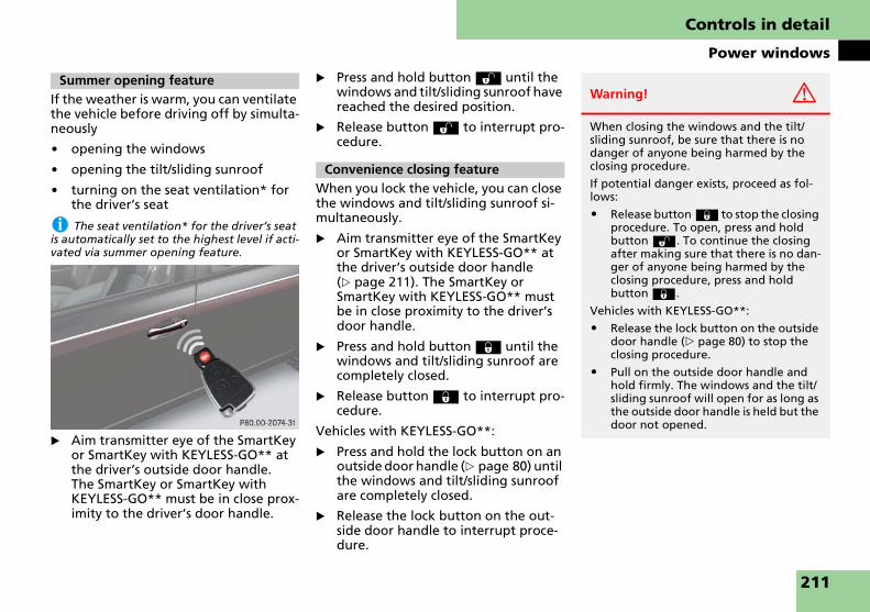
Controls in detail
Power windows
If the weather is warm, you can ventilate the vehicle before driving off by simulta-neously
� opening the windows
� opening the tilt/sliding sunroof
� turning on the seat ventilation* for the driver’s seat
i The seat ventilation* for the driver’s seat is automatically set to the highest level if acti-vated via summer opening feature.
� Aim transmitter eye of the SmartKey or SmartKey with KEYLESS-GO** at the driver’s outside door handle. The SmartKey or SmartKey with KEYLESS-GO** must be in close prox-imity to the driver’s door handle.
� Press and hold button Œ until the windows and tilt/sliding sunroof have reached the desired position.
� Release button Œ to interrupt pro-cedure.
When you lock the vehicle, you can close the windows and tilt/sliding sunroof si-multaneously.
� Aim transmitter eye of the SmartKey or SmartKey with KEYLESS-GO** at the driver’s outside door handle (� page 211). The SmartKey or SmartKey with KEYLESS-GO** must be in close proximity to the driver’s door handle.
� Press and hold button ‹ until the windows and tilt/sliding sunroof are completely closed.
� Release button ‹ to interrupt pro-cedure.
Vehicles with KEYLESS-GO**:
� Press and hold the lock button on an outside door handle (� page 80) until the windows and tilt/sliding sunroof are completely closed.
� Release the lock button on the out-side door handle to interrupt proce-dure.
Summer opening feature
Convenience closing feature
Warning! G
When closing the windows and the tilt/ sliding sunroof, be sure that there is no danger of anyone being harmed by the closing procedure.
If potential danger exists, proceed as fol-lows:
� Release button ‹ to stop the closing procedure. To open, press and hold button Œ. To continue the closing after making sure that there is no dan-ger of anyone being harmed by the closing procedure, press and hold button ‹.
Vehicles with KEYLESS-GO**:
� Release the lock button on the outside door handle (� page 80) to stop the closing procedure.
� Pull on the outside door handle and hold firmly. The windows and the tilt/sliding sunroof will open for as long as the outside door handle is held but the door not opened.
211

Controls in detail
Power tilt/sliding sunroof
The tilt/sliding sunroof is opened and closed electrically. The switch for the tilt/sliding sunroof is on the overhead con-trol panel.
Sunroof switch
1 Push back to slide sunroof open2 Push forward to slide sunroof closed3 Pull down to lower sunroof at rear4 Push up to raise sunroof at rear
5 Screen
With the sunroof closed or tilted open, screen 5 can be slid into the roof open-ing to help provide shade. When sliding the sunroof open, the screen will also re-tract.
! To avoid damaging the seals, do not transport any objects with sharp edges which can stick out of the tilt/sliding sunroof.
Do not open the tilt/sliding sunroof if there is snow or ice on the roof, as this could result in malfunctions.
The tilt/sliding sunroof can be opened or closed manually should an electrical malfunc-tion occur (� page 403).
Power tilt/sliding sunroof
Opening and closing the power tilt/sliding sunroof (Maybach 57)
Warning! G
When closing the tilt/sliding sunroof, make sure there is no danger of anyone being harmed by the closing procedure.
The opening/closing procedure of the tilt/sliding sunroof can be immediately halted by releasing the switch or, if the switch was moved past the resistance point and re-leased, by moving the switch in any direc-tion.
The tilt/sliding sunroof is made out of glass. In the event of an accident, the glass may shatter. This may result in an opening in the roof.
In a vehicle rollover, occupants not wear-ing their seat belts or not wearing them properly may be thrown out of the open-ing. Such an opening also presents a po-tential for injury for occupants wearing their seat belts properly as entire body parts or portions of them may protrude from the passenger compartment.
When leaving the vehicle, always remove the SmartKey or SmartKey with KEYLESS-GO** from the starter switch, take it with you, and lock the vehicle. Do not leave children unattended in the vehi-cle, or with access to an unlocked vehicle. A child’s unsupervised access to a vehicle could result in an accident and/or serious personal injury.
212
Controls in detail
Power tilt/sliding sunroof
! Please keep in mind that weather conditions can sometimes change rapidly. Make sure to close the tilt/sliding sunroof when leaving the vehicle. If water enters the vehicle interior, vehicle electronics could be damaged which is not covered by the Maybach Limited Warranty.
i When the tilt/sliding sunroof is open, res-onance noises may result in addition to the usual wind noises. They are caused by minimal pressure changes in the passenger compart-ment. To reduce or eliminate these noises, change the position of the tilt/sliding sunroof or open a side window slightly.
i You can also open or close the tilt/sliding sunroof using the SmartKey, see “Summer opening feature” (� page 211) and “Conve-nience closing feature” (� page 211).
Depending on current position, the tilt/sliding sunroof may also open or close when the air recirculation button , or the charcoal filter button e (� page 193) is pressed and held for 2 seconds.
i With the SmartKey in starter switch posi-tion 0 or removed from the starter switch, the tilt/sliding sunroof can be operated
� until you open the driver’s or passenger door
� for up to approximately 5 minutes
� Switch on the ignition (� page 60).
Opening and closing the power tilt/slid-ing sunroof
� To open, close, raise or lower the tilt/sliding sunroof, move the switch to the resistance point in the required direction 1 to 4.
� Release the sunroof switch when the tilt/sliding sunroof has reached the desired position.
Fully opening (Express-open) and clos-ing (Express-close) the power tilt/sliding sunroof
� To open, close, raise or lower the tilt/sliding sunroof, move the switch past the resistance point in the required direction 1 to 4 and release.
The tilt/sliding sunroof opens or clos-es completely.
Stopping the power tilt/sliding sunroof
� Move the switch in any direction.
i If the movement of the tilt/sliding sunroof is blocked during the closing procedure, the sunroof will stop and reopen slightly.
The tilt/sliding sunroof must be synchro-nized
� after the consumer battery has been disconnected
� the tilt/sliding sunroof has been closed manually
� a malfunction
� the tilt/sliding sunroof does not open smoothly
� Remove the respective fuse from the fuse box (� page 426).
� Reinsert the fuse in the main fuse box.
� Switch on the ignition (� page 60).
� Move and hold the sunroof switch in direction of arrow 4 until the tilt/sliding sunroof is fully raised at the rear.
� Keep holding the sunroof switch in direction of arrow 4 for approxi-mately 1 second.
� Check the Express-open feature.
If the tilt/sliding sunroof opens com-pletely, the roof is synchronized. Oth-erwise repeat the above steps.
Synchronizing the power tilt/sliding sunroof (Maybach 57)
213

Controls in detail
Power tilt/sliding sunroof
The tilt/sliding sunroof is opened and closed electrically.
You can operate the tilt/sliding sunroof from the cockpit or from the rear passen-ger compartment.
! To avoid damaging the seals, do not transport any objects with sharp edges which can stick out of the tilt/sliding sunroof.
Do not open the tilt/sliding sunroof if there is snow or ice on the roof, as this could result in malfunctions.
The tilt/sliding sunroof can be opened or closed manually should an electrical malfunc-tion occur (� page 403).
i You can also open or close the tilt/sliding sunroof using the SmartKey, see “Summer opening feature” (� page 211) and “Conve-nience closing feature” (� page 211).
Depending on current position, the tilt/sliding sunroof may also open or close when the air recirculation button , or the charcoal filter button e (� page 193) is pressed and held for two seconds.
i With the SmartKey in starter switch posi-tion 0 or removed from the starter switch, the tilt/sliding sunroof can be operated
� until you open the driver’s or passenger door
� for up to approximately 5 minutes
� Switch on the ignition (� page 60).
Opening and closing the power tilt/sliding sunroof (Maybach 62)
Warning! G
When closing the tilt/sliding sunroof, make sure there is no danger of anyone being harmed by the closing procedure.
The opening/closing procedure of the tilt/sliding sunroof can be immediately halted by releasing the switch or, if the switch was moved past the resistance point and re-leased, by moving the switch in any direc-tion.
The tilt/sliding sunroof is made out of glass. In the event of an accident, the glass may shatter. This may result in an opening in the roof.
In a vehicle rollover, occupants not wear-ing their seat belts or not wearing them properly may be thrown out of the open-ing. Such an opening also presents a po-tential for injury for occupants wearing their seat belts properly as entire body parts or portions of them may protrude from the passenger compartment.
When leaving the vehicle, always remove the SmartKey or SmartKey with KEYLESS-GO** from the starter switch, take it with you, and lock the vehicle. Do not leave children unattended in the vehi-cle, or with access to an unlocked vehicle. A child’s unsupervised access to a vehicle could result in an accident and/or serious personal injury.
Warning! G
When closing the screen, make sure no one can be caught and/or injured.
In case of danger, release the switch and, if necessary, push the switch in direction “open”.
214

Controls in detail
Power tilt/sliding sunroof
Operating from the cockpit
The switch for the tilt/sliding sunroof is on the overhead control panel.
Sunroof switch, front
1 Push back to slide screen or sunroof open
2 Push forward to slide screen or sun-roof closed
3 Pull down to lower sunroof at rear4 Push up to raise sunroof at rear
i If the screen is closed, the screen opens first when you push the sunroof switch in di-rection of arrow 1.
Push the sunroof switch again in direction of arrow 1 to open the tilt/sliding sunroof.
The screen only operates with the tilt/sliding sunroof closed.
Opening and closing the screen
� To open or close the screen, move the sunroof switch to the resistance point in the required direction of arrow 1 or 2.
Release the sunroof switch when the screen has reached the desired posi-tion.
Opening and closing the power tilt/slid-ing sunroof
� Open the screen if it is closed.
� To open, close, raise, or lower the tilt/sliding sunroof, move the sunroof switch to resistance point in the re-quired direction of arrows 1 to 4.
� Release the sunroof switch when the tilt/sliding sunroof has reached the desired position.
Fully opening (Express-open) and clos-ing (Express-close) the power tilt/sliding sunroof
� Open the screen if it is closed.
� To open, close, raise, or lower the tilt/sliding sunroof, move the sunroof switch past the resistance point in the required direction of arrows 1 to 4 and release.
The tilt/sliding sunroof opens or clos-es completely.
Stopping the power tilt/sliding sunroof during Express-operation
� Move the switch in any direction.
i If the movement of the tilt/sliding sunroof is blocked during the closing procedure, the tilt/sliding sunroof will stop and reopen slight-ly.
215

Controls in detail
Power tilt/sliding sunroof
Operating from the rear passenger com-partment
The switches are in the storage compart-ment under the rear center armrest.
Sunroof switches, rear
1 Press to lower sunroof at rear2 Press to slide screen or sunroof closed3 Press to slide screen or sunroof open4 Switch for screen and sliding portion
of roof5 Press to raise sunroof at rear6 Switch for tilt portion of roof
The switches are in the storage compart-ment in the rear center armrest.
Sunroof switches, rear (vehicles with rear center seat*)
1 Press to lower sunroof at rear2 Press to slide screen or sunroof closed3 Press to slide screen or sunroof open4 Switch for screen and sliding portion
of roof5 Press to raise sunroof at rear6 Switch for tilt portion of roof
i If the screen is closed, the screen will open first when you press sunroof switch 4 at 3.
Press sunroof switch 4 again at 3 to open the tilt/sliding sunroof.
The screen only operates with the tilt/sliding sunroof closed.
� Switch on the ignition (� page 60).
Opening and closing the screen
� To open or close the screen, press sunroof switch 4 at 3 or 2.
Release the sunroof switch when the screen has reached the desired posi-tion.
Fully opening (Express-open) and clos-ing (Express-close) the screen
� To open or close the screen, press sunroof switch 4 past the resistance point at 3 or 2 and release.
� The screen opens or closes complete-ly.
Opening and closing the power tilt/slid-ing sunroof
� Open the screen if it is closed.
� To open or close the tilt/sliding sun-roof, press sunroof switch 4 to the resistance point at 3 or 2.
� Release sunroof switch 4 when the tilt/sliding sunroof has reached the desired position.
216

Controls in detail
Power tilt/sliding sunroof
Fully opening (Express-open) and clos-ing (Express-close) the power tilt/sliding sunroof
� Open the screen if it is closed.
� To open or close the tilt/sliding sun-roof, press sunroof switch 4 past the resistance point at 3 or 2 and re-lease.
The rear tilt/sliding sunroof opens or closes completely.
Stopping the power tilt/sliding sunroof during Express-operation
� Press sunroof switch 4 again.
i If the movement of the tilt/sliding sunroof is blocked during the closing procedure, the tilt/sliding sunroof will stop and reopen slight-ly.
Raising and lowering the power tilt/slid-ing sunroof
� Open the screen if it is closed.
� To raise or lower the tilt/sliding sun-roof, press sunroof switch 6 to the resistance point at 1 or 5.
� Release sunroof switch 6 when the tilt/sliding sunroof has reached the desired position.
Fully raising and lowering the power tilt/sliding sunroof
� Open the screen if it is closed.
� To raise or lower the tilt/sliding sun-roof, press sunroof switch 6 past the resistance point at 1 or 5 and re-lease.
� To stop the procedure, press the switch again.
The tilt/sliding sunroof must be synchro-nized
� after the consumer battery has been disconnected
� the tilt/sliding sunroof has been oper-ated manually
� a malfunction
� the tilt/sliding sunroof does not open smoothly
� Remove the respective fuse from the fuse box (� page 426).
� Reinsert the fuse in the main fuse box.
� Switch on the ignition (� page 60).
� If the tilt/sliding sunroof is raised at the rear, lower and close it.
� Move and hold the sunroof switch in direction of arrow 4 (� page 215) or press sunroof switch 6 at 5 (� page 216) until the tilt/sliding sun-roof is fully raised at the rear.
� Keep pressing the respective switch for approximately 1 second.
� Check the Express-open feature (� page 215).
If the tilt/sliding sunroof opens com-pletely, the roof is synchronized. Oth-erwise repeat the above steps.
Synchronizing the power tilt/sliding sunroof (Maybach 62)
217

Controls in detail
Electrotransparent roof*
You can operate the electrotransparent roof from the cockpit or from the rear passenger compartment.
i With the SmartKey in starter switch posi-tion 0 or removed from the starter switch, the electrotransparent roof can be operated
� until you open the driver’s or passenger door
� for up to approximately 5 minutes.
� Switch on the ignition (� page 60).
Operating from the cockpit
The switch for the electrotransparent roof is on the overhead control unit.
Electrotransparent roof switches, front
1 Push back to slide screen closed2 Push forward to slide screen open3 Pull down to make the electrotrans-
parent roof opaque/switch off roof lighting
4 Push up to make the electrotranspar-ent roof transparent/switch on roof lighting
Electrotransparent roof*
Operating the electrotransparent roof
Warning! G
When closing the screen, make sure no one can be caught and/or injured.
In case of danger, release the switch and, if necessary, push the switch in direction “open”.
The electrotransparent roof is made out of glass. In the event of an accident, the glass may shatter. This may result in an opening in the roof.
In a vehicle rollover, occupants not wear-ing their seat belts or not wearing them properly may be thrown out of the open-ing. Such an opening also presents a po-tential for injury for occupants wearing their seat belts properly as entire body parts or portions of them may protrude from the passenger compartment.
When leaving the vehicle, always remove the SmartKey or SmartKey with KEYLESS-GO** from the starter switch, take it with you, and lock the vehicle. Do not leave children unattended in the vehi-cle, or with access to an unlocked vehicle. A child’s unsupervised access to a vehicle could result in an accident and/or serious personal injury.
218

Controls in detail
Electrotransparent roof*
Opening the screen
� Slide the switch to the resistance point in direction of arrow 2.
� Release the switch when the screen has reached the desired position.
Closing the screen
� Move the switch to the resistance point in direction of arrow 1.
� Release the switch when the screen has reached the desired position.
Fully opening the screen (Express-open)
� Move the switch past the resistance point in direction of arrow 2 and re-lease.
The screen opens completely.
Fully closing the screen (Express-close)
� Move the switch past the resistance point in direction of arrow 1 and re-lease.
The electrotransparent roof turns opaque and the screen closes com-pletely.
Stopping the screen during Express-operation
� Move the switch in any direction.
Making the electrotransparent roof transparent
The screen must be completely open.
� Push the switch in direction of arrow 4.
Making the electrotransparent roof opaque
The screen must be completely open.
� Pull the switch in direction of arrow 3.
Switching on roof lighting
The screen must be completely closed.
� Press the switch in direction of arrow 4.
Switching off roof lighting
� Pull the switch in direction of arrow 3.
Operating from the rear passenger com-partment
The switches are in the storage compart-ment under the rear center armrest.
Electrotransparent roof switches, rear
1 Press to make roof opaque2 Press to slide screen closed3 Press to slide screen open4 Switch for screen5 Press to make roof transparent6 Switch for electrotransparent roof
219

Controls in detail
Electrotransparent roof*
Electrotransparent roof switches, rear (vehi-cles with rear center seat*)
1 Press to make roof opaque2 Press to slide screen closed3 Press to slide screen open4 Switch for screen5 Press to make roof transparent6 Switch for electrotransparent roof
Opening and closing the screen
� To open or close the screen, press switch 4 to the resistance point at 3 or 2.
Release the switch when the screen has reached the desired position.
Fully opening (Express-open) and clos-ing (Express-close) the screen
� To open or close the screen, press switch 4 past the resistance point at 3 or 2 and release.
The screen opens or closes completely.
Stopping the screen during Express-operation
� Press switch 4 again.
Making the electrotransparent roof transparent
� Press switch 6 at 5.
The screen opens automatically and the electrotransparent roof turns transparent.
Making the electrotransparent roof opaque
� If the screen is closed, open it com-pletely.
� Press switch 6 at 1.
The electrotransparent roof turns opaque.
220

Controls in detail
Driving systems
The driving systems of your vehicle are described on the following pages:
� Cruise control and Distronic**, with which the vehicle can maintain a pre-set speed.
� Airmatic DC adjusts the vehicle sus-pension characteristics automatically and controls the vehicle level.
� Vehicle level control, with which you can change the vehicle level.
� Parktronic and Parking Assist System (PAS), which serves as a parking assis-tant.
For information on the BAS, ABS, ESP® and electro-hydraulic brake, see “Driving safety systems” (� page 103).
Cruise control automatically maintains the speed you set for your vehicle.
Use of cruise control is recommended for driving at a constant speed for extended periods of time. You can set or resume cruise control at any speed over 20 mph (30 km/h).
The cruise control function is operated by means of the cruise control lever.
Cruise control lever
The cruise control lever is the uppermost lever on the left-hand side of the steer-ing column.
1 Sets current or higher speed2 Sets current or lower speed3 Cancels cruise control4 Resume at last set speed
Driving systems
Cruise control
Warning! G
Cruise control is a convenience system de-signed to assist the driver during vehicle operation. The driver is and must always remain responsible for the vehicle’s speed and for safe brake operation.
Only use cruise control if the road, traffic and weather conditions make it advisable to travel at a steady speed.
� The use of cruise control can be dan-gerous on winding roads or in heavy traffic because conditions do not allow safe driving at a steady speed.
� The use of cruise control can be dan-gerous on slippery roads. Rapid chang-es in tire traction can result in wheel spin and loss of control.
� Deactivate cruise control when driving in fog.
The “Resume” function should only be op-erated if the driver is fully aware of the previously set speed and wishes to resume this particular preset speed.
221

Controls in detail
Driving systems
Setting current speed
� Accelerate or decelerate to the de-sired speed.
� Briefly lift the cruise control lever in direction of arrow 1 or depress in di-rection of arrow 2.
The current speed is set.
� Remove your foot from the accelera-tor pedal.
Cruise control is activated.
The selected speed appears in the multi-function display for approximately 5 seconds, and the corresponding speed-ometer segments from the selected speed to the vehicle maximum speed are illuminated.
i On uphill or downhill grades, cruise con-trol may not be able to maintain the set speed. Once the grade eases, the set speed will be resumed.
Canceling cruise control
There are several ways to cancel cruise control:
� Step on the brake pedal.
Cruise control is canceled. The last speed set is stored for later use.
or
� Briefly push the cruise control lever in direction of arrow 3.
Cruise control is canceled. The last speed set is stored for later use.
! Moving the gear selector lever to position N while driving also cancels cruise control. However, the gear selector lever should not be moved to position N while driv-ing, except to coast when the vehicle is in dan-ger of skidding (e.g. on icy roads).
i The last stored speed is canceled when you turn off the engine.
Setting a higher speed
� Lift the cruise control lever in direc-tion of arrow 1 (� page 221) and hold it until the desired speed is reached.
� Release the cruise control lever.
The new speed is set.
i Depressing the accelerator pedal does not deactivate cruise control. After brief accelera-tion (e.g. for passing), cruise control resumes the last speed set.
Setting a lower speed
� Depress the cruise control lever in di-rection of arrow 2 (� page 221) and hold it until the desired speed is reached.
� Release the cruise control lever.
The new speed is set.
i When you use the cruise control lever to decelerate, the transmission will automatical-ly downshift if the engine’s braking power does not slow the vehicle sufficiently.
Fine adjustment in 1 mph (Canada: 1 km/h) increments
Faster
� Briefly tip the cruise control lever in direction of arrow 1 (� page 221).
Slower
� Briefly tip the cruise control lever in direction of arrow 2 (� page 221).
222

Controls in detail
Driving systems
Setting to last stored speed (“Resume” function)
� Briefly push the cruise control lever in direction of arrow 4 (� page 221).
The cruise control resumes the last set speed.
� Remove your foot from the accelera-tor pedal.
The selected speed appears in the multi-function display for approximately 5 seconds, and the corresponding speed-ometer segments from the selected speed to the vehicle maximum speed are illuminated.
When activated, the Distronic adaptive cruise control system increases driving convenience afforded by the cruise con-trol during travel on expressways and other major roads.
� If the Distronic distance sensor de-tects a slower moving vehicle directly ahead, your vehicle speed will be re-duced so that you follow that vehicle at a preset distance.
� If there is no vehicle directly ahead of you, Distronic will function in the same way as cruise control (� page 221).
Warning! G
The speed stored in memory should only be set again if prevailing road conditions permit. Possible acceleration or decelera-tion differences arising from returning to preset speed could cause an accident and/or serious injury to you and others.
Distronic**
Warning! G
Distronic adaptive cruise control is no sub-stitute for active driving involvement. It does not react to stationary objects, nor does it recognize or predict the curvature and lane layout or the movement of vehi-cles ahead. Distronic can only apply a max-imum of 20% of the vehicle’s braking power.
It is the driver’s responsibility at all times to be attentive to road, traffic and weather conditions and to provide the steering, braking and other driving inputs necessary to retain control of the vehicle.
Warning! G
Distronic is a convenience system. Its speed adjustment reduction capability is intend-ed to make cruise control more effective and usable when traffic speeds vary. How-ever, it is not intended to, nor does it, re-place the need for extreme care. The responsibility for the vehicle speed and the distance to the vehicle ahead, including most importantly brake operation to as-sure safe stopping distance, always rests with the driver.
Distronic cannot take street and traffic conditions into account.
Warning! G
Distronic requires familiarity with its oper-ational characteristics. We strongly recom-mend that you review the following information carefully before operating the system.
223

Controls in detail
Driving systems
i USA only:This device has been approved by the FCC as a “Vehicular Radar System”. The radar sensor is intended for use in an automotive radar sys-tem only. Removal, tampering, or altering of the device will void any warranties, and is not permitted by the FCC. Do not tamper with, al-ter, or use in any non-approved way.Any unauthorized modification to this device could void the user’s authority to operate the equipment.
i Canada only:This device complies with RSS-210 of Industry Canada. Operation is subject to the following two conditions:
(1) This device may not cause interference, and
(2) this device must accept any interference received, including interference that may cause undesired operation of the device.
Removal, tampering, or altering of the device will void any warranties, and is not permitted. Do not tamper with, alter, or use in any non-approved way.Any unauthorized modification to this device could void the user’s authority to operate the equipment.
Warning! G
Distronic cannot take street and traffic conditions into account. Only use Distronic if the road, weather and traffic conditions make it advisable to travel at a steady speed.
Warning! G
Use of Distronic can be dangerous on slip-pery roads. Rapid changes in tire traction can result in wheel spin and loss of control.
Distronic does not act upon adverse sight distance conditions. Do not use Distronic during conditions of fog and heavy rain, snow or sleet.
Warning! G
Distronic cannot take weather conditions into account. Switch off Distronic or do not turn it on if:
� roads are slippery or covered with snow or ice. The wheels could lose trac-tion while braking or accelerating, and the vehicle could skid
� the sensor is dirty or visibility is dimin-ished due to snow, rain or fog. The dis-tance control could be impaired
Always pay attention to traffic conditions even while Distronic is switched on. Other-wise, you may not be able to recognize dangerous situations until it is too late and could cause an accident resulting in per-sonal or fatal injury to you or others.
Warning! G
Close attention to road and traffic condi-tions is imperative at all times, regardless of whether or not Distronic is activated.
Use of Distronic can be dangerous on winding roads or in heavy traffic because conditions do not allow safe driving at a steady speed.
Distronic will not react to stationary ob-jects in the roadway (e.g. a stopped vehicle in a traffic jam or a disabled vehicle). Dis-tronic will also not respond to oncoming vehicles.
Switch off Distronic:
� when changing from the left to the right lane if vehicles are moving more slowly in the left lane
� when entering a turn lane or highway off ramp
224

Controls in detail
Driving systems
Distronic displays in the speedometer dial
Set speed
If Distronic is activated, one or two seg-ments come on around the set speed.
i The vehicle speed displayed on the speed-ometer can briefly vary from the speed setting on the Distronic system.
Segments
If Distronic detects a vehicle directly ahead, the segments from the speed of the vehicle ahead to the set speed come on.
If Distronic calculates that there is a dan-ger of collision
� the distance warning lamp l in the instrument cluster comes on red
� an intermittent warning sounds
� Immediately brake the vehicle to avoid a collision.
Under no circumstances should the driver await the intermittent warning sound before braking. See the fol-lowing warning note.
The intermittent warning sound ceas-es and the red distance warning lamp l goes out when the neces-sary distance to the vehicle ahead is again established.
� in complex driving situations, such as in highway construction zones
In these situations, Distronic will continue to maintain the set speed unless deactivat-ed. Distronic is designed and intended only to maintain a set speed and keep a set dis-tance from moving objects in front of it.
Warning! G
The “Resume” function should only be op-erated if the driver is fully aware of the previously set speed and wishes to resume this particular preset speed.
225

Controls in detail
Driving systems
Distronic menu in the control system
In the Distronic menu you can read the current settings for Distronic. What ap-pears in the display depends on whether Distronic and the distance warning func-tion are turned on or off.
� Press button è or ÿ repeatedly until you see one of the following dis-plays.
Distronic deactivated
If Distronic is deactivated, you can see the standard display of Distronic in the multifunction display.
1 Vehicle ahead, if detected2 Actual distance to vehicle ahead3 Preset distance threshold to vehicle
ahead4 Your vehicle5 Symbol for activated distance warn-
ing function
Warning! G
An intermittent warning sounds and the distance warning lamp l in the instru-ment cluster is illuminated if the Distronic system calculates that the distance to the vehicle ahead and your vehicle’s current speed indicate that Distronic will not be ca-pable of slowing the vehicle sufficiently to maintain the preset following distance, which creates a danger of a collision.
Immediately brake the vehicle to increase the distance between your vehicle and the vehicle in front of you. The warning sound is intended as a final caution that you have not interceded with your own braking in-puts to avoid a potentially dangerous situ-ation. Do not wait for the operation of the warning signal to intercede with your own braking, as that will result in potentially dangerous emergency braking which will not always result in an impact being avoid-ed.
Tailgating increases the risk of an accident.
Warning! G
Distronic brakes your vehicle with a maxi-mum of 6.5 ft/s2 (2 m/s2). This corresponds to about 20% of the maximum decelera-tion ability of your vehicle.
Distronic brakes the vehicle in an effort to restore the preset distance or to maintain the speed. The brake pedal is automatical-ly applied as this happens which results in the brake pedal moving.
Keep driver’s foot area clear at all times, including the area under the brake pedal. Objects stored in this area may impair ped-al movement which could interfere with the braking ability of the Distronic system.
Do not place your foot under the brake pedal – your foot could become caught.
226

Controls in detail
Driving systems
Distronic activated
If you turn Distronic on, you will see the set speed in the multifunction display for about 5 seconds. If Distronic is activated, you then see the following display in the multifunction display.
1 Distronic activated
Cruise control lever
The Distronic system is operated by means of the cruise control lever.
The cruise control lever is the uppermost lever on the left-hand side of the steer-ing column.
1 Sets current or higher speed2 Sets current or lower speed3 Deactivates Distronic4 Resumes at last set speed
Activating Distronic
You can activate Distronic when
� you are driving above 25 mph (40 km/h)
� the ESP® is activated (� page 107)
i The maximum speed you can set is 110 mph (180 km/h).
If Distronic has not been activated after pressing the cruise control lever you will see the message --- in the multifunction display.
In the following cases you cannot acti-vate Distronic:
� up to 2 minutes after starting the en-gine
� when you brake
� if you have set the parking brake
� if the gear selector lever is in position P, R or N
� if the ESP® is switched off
227
Controls in detail
Driving systems
Setting the current speed
� Accelerate or decelerate to the de-sired speed.
� Briefly lift the cruise control lever in direction of arrow 1 or depress in di-rection of arrow 2.
Distronic is activated and the current speed is set.
� Remove your foot from the accelera-tor pedal.
i If you do not take your foot off of the ac-celerator completely, the following message will appear in the multifunction display:
DISTRONICOVERRIDEDistronic will not work to maintain the dis-tance to slower moving vehicles in front of you. Your vehicle speed will then be deter-mined only by the accelerator pedal position.
Setting a higher speed
� Briefly tip the cruise control lever in direction of arrow 1 (� page 227) to increase vehicle speed in increments of 5 mph (Canada: 10 km/h).
The new speed is set.
The stored speed is displayed in the multifunction display for approxi-mately 5 seconds, and one or two segments around the stored speed come on in the speedometer (� page 225).
i Depressing the accelerator pedal does not deactivate Distronic. After brief acceleration (e.g. for passing), the cruise control resumes the last speed set.
Setting a lower speed
� Briefly tip the cruise control lever in direction of arrow 2 (� page 227) to decrease vehicle speed in increments of 5 mph (Canada: 10 km/h).
The new speed is set.
The stored speed is displayed in the multifunction display for approxi-mately 5 seconds, and one or two segments around the stored speed come on in the speedometer (� page 225).
i When you use the cruise control lever to decelerate, the brakes will be applied to sup-port deceleration.
In addition, the transmission will automatical-ly downshift on long downhill grades.
Fine adjustment in 1 mph (Canada: 1 km/h) increments
Faster
� Briefly tip the cruise control lever in direction of arrow 4 (� page 227).
228

Controls in detail
Driving systems
Setting to last stored speed (“Resume” function)
� Briefly tip the cruise control lever in direction of arrow 4 (� page 227).
Distronic is set to the last stored speed.
� Remove your foot from the accelera-tor pedal.
Deactivating Distronic
There are several ways to deactivate the Distronic system:
� Briefly tip the cruise control lever in direction of arrow 3 (� page 227).
or
� Step on the brake pedal.
Distronic is deactivated. The last speed set is stored into memory.
i The following message will appear in the multifunction display for approximately 5 seconds:
DISTRONIC OFFThe last stored speed is deleted when you turn off the engine.
Distronic deactivates automatically when:
� You set the parking brake.
� You drive slower than 22 mph (35 km/h).
� The ESP® is active (� page 107) or you deactivate the ESP®.
� You move the transmission gear se-lector lever into position N.
A signal will sound. The DISTRONIC OFF message appears in the multi-function display for approximately 5 seconds.
Setting the following distance in Distronic
You can set the specified following dis-tance for Distronic by varying the time setting between 1.0 and 2.0 seconds. Us-ing this time setting and the current speed of your vehicle, Distronic calcu-lates and sets the required following dis-tance to the vehicle ahead. The set distance will be shown in the multifunc-tion display.
Warning! G
The speed stored in memory should only be set again if prevailing road conditions permit. Possible acceleration or decelera-tion differences arising from returning to preset speed could cause an accident and/or serious injury to you and others.
Warning! G
Distronic switches off and releases the brakes when the vehicle decelerates below the minimum speed of approximately 22 mph (35 km/h) by operation of the sys-tem. At that time the driver must apply the brakes in order to reduce vehicle speed further or bring it to a stop.
Warning! G
It is up to the driver to exercise discretion to select the appropriate setting given road conditions, traffic, driver’s preferred driving style and applicable laws and driv-ing recommendations for safe following distance.
229
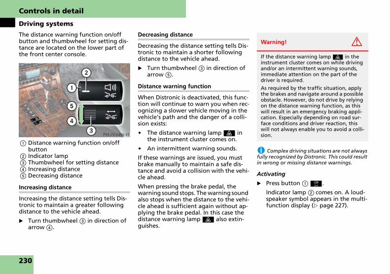
Controls in detail
Driving systems
The distance warning function on/off button and thumbwheel for setting dis-tance are located on the lower part of the front center console.
1 Distance warning function on/off button
2 Indicator lamp3 Thumbwheel for setting distance4 Increasing distance5 Decreasing distance
Increasing distance
Increasing the distance setting tells Dis-tronic to maintain a greater following distance to the vehicle ahead.
� Turn thumbwheel 3 in direction of arrow 4.
Decreasing distance
Decreasing the distance setting tells Dis-tronic to maintain a shorter following distance to the vehicle ahead.
� Turn thumbwheel 3 in direction of arrow 5.
Distance warning function
When Distronic is deactivated, this func-tion will continue to warn you when rec-ognizing a slower vehicle moving in the vehicle’s path and the danger of a colli-sion exists:
� The distance warning lamp l in the instrument cluster comes on.
� An intermittent warning sounds.
If these warnings are issued, you must brake manually to maintain a safe dis-tance and avoid a collision with the vehi-cle ahead.
When pressing the brake pedal, the warning sound stops. The warning sound also stops when the distance to the vehi-cle ahead is sufficient again without ap-plying the brake pedal. In this case the distance warning lamp l also extin-guishes.
i Complex driving situations are not always fully recognized by Distronic. This could result in wrong or missing distance warnings.
Activating
� Press button 1 {.
Indicator lamp 2 comes on. A loud-speaker symbol appears in the multi-function display (� page 227).
Warning! G
If the distance warning lamp l in the instrument cluster comes on while driving and/or an intermittent warning sounds, immediate attention on the part of the driver is required.
As required by the traffic situation, apply the brakes and navigate around a possible obstacle. However, do not drive by relying on the distance warning function, as this will result in an emergency braking appli-cation. Especially depending on road sur-face conditions and driver reaction, this will not always enable you to avoid a colli-sion.
230

Controls in detail
Driving systems
Deactivating
� Press button 1 {.
The indicator lamp 2 on the button goes out. No loudspeaker symbol ap-pears in the multifunction display.
Driving with Distronic
This section describes a number of driv-ing situations where special precaution is required on the part of the driver. Be prepared to brake in such situations. This will deactivate the Distronic system.
The most likely cause for a malfunction-ing system is a dirty sensor (located be-hind the hood grille), especially at times of snow and ice or heavy rain. In such a case, Distronic will switch off, and the message:
DISTRONICCURRENTLYUNAVAILABLESEE OPERATORS MANUAL
appears in the multifunction display.
For cleaning and care of the Distronic sensor, see “Cleaning the Distronic sys-tem sensor” (� page 346).
i If the message:
DISTRONICCURRENTLY UNAVAILABLE SEE OPERATORS MANUALdisappears during driving and last speed stored flashes for approximately 5 seconds, the dirt (e.g. slush) has dissolved; Distronic is again operational.
Turns and bends
In turns or bends, Distronic may not de-tect a moving vehicle in front, or it may detect one too soon. This may cause your vehicle to brake late or unexpectedly.
Warning! G
Distronic works to maintain the speed se-lected by the driver unless a moving obsta-cle proceeding directly ahead of it in the same travel direction is detected (e.g. fol-lowing another vehicle ahead of you at a distance set by Distronic). This means that:
� Your vehicle can pass another vehicle after you change lanes.
� While in a sharp turn or if the vehicle in front is in a sharp turn, Distronic could lose sight of a vehicle traveling in front of it, then your vehicle could accelerate to the previously selected speed.
Distronic regulates only the distance be-tween your vehicle and those directly ahead of it, but does not register station-ary objects in the road, e.g.:
� a stopped vehicle in a traffic jam
� a disabled vehicle
� an oncoming vehicle
The driver must always be on the alert, ob-serve all traffic and intercede as required by steering or braking the vehicle.
Warning! G
Distronic should not be used in snowy or icy road conditions.
231

Controls in detail
Driving systems
Offset driving
A vehicle traveling in your lane but offset from your direct line of travel may not be detected by Distronic. There will be in-sufficient distance to the vehicle ahead.
Lane changing
Distronic has not yet detected the vehicle changing lanes. There will be insufficient distance to the lane changing vehicle.
Narrow vehicles
Because of their narrow profiles, the ve-hicles traveling near the outer edges of the lane have not yet been detected by Distronic. There will be insufficient dis-tance to the vehicles ahead.
232

Controls in detail
Driving systems
Airmatic automatically selects the opti-mum suspension tuning and ride height for your vehicle. Airmatic consists of three components:
� Adaptive Damping System (ADS)
� Stiffness of spring
� Vehicle level control
The ADS automatically selects the opti-mum damping for the respective driving conditions. At the same time the suspen-sion is set to either sporty or regular.
Damping and suspension are adjusted automatically according to your driving style and road conditions. In addition to the automatic mode designed for your convenience, you can adjust the suspen-sion tuning yourself by selecting from two other levels using the button on the center console.
Suspension tuning
The suspension tuning is set according to:
� Your driving style
� Road surface conditions
� Your choice of suspension style, “Comfort”, “Sporty 1” or “Sporty 2”, which you select using the damping button.
1 Damping button2 Indicator lamp3 Indicator lamp
Airmatic DC (Dual Control)
��
233

Controls in detail
Driving systems
�
� Start the engine (� page 60).� Press damping button 1 until the de-sired suspension style is set.
� If both indicator lamps are out, you have chosen the automatic mode for soft damping. The mes-sage:
AIRMATIC DCCONVENIENCE
for Comfort suspension tuning appears in the multifunction dis-play.
� If one indicator lamp is on, the control system supports a primari-ly dynamic style of driving. The message:
AIRMATIC DC SPORTS 1
for Sporty 1 suspension tuning ap-pears in the multifunction display.
� If both indicator lamps are on, the system is set for a dynamic style of driving. The message:
AIRMATIC DC SPORTS 2
for Sporty 2 suspension tuning ap-pears in the multifunction display.
i The selected suspension style is stored in memory, even after the SmartKey is removed from the starter switch.
Vehicle level control
Your vehicle automatically adjusts its ride height to
� increase vehicle safety
� reduce fuel consumption
�
Warning! G
To help avoid personal injury, keep hands and feet away from wheel housing area, and stay away from under the vehicle when lowering the vehicle chassis.
234

Controls in detail
Driving systems
The following vehicle level settings can be selected when the vehicle is stationary (Maybach 57, Maybach 62):
The normal level of the Maybach 57 S is 0.6 in (15 mm) lower than for other mod-els. The data given in the following table is based on the normal vehicle level of the Maybach 57 S:
The button is located on the lower part of the front center console.
Vehicle level when stationary
Indicator lamp Use for Ride height increase over normal
Automatic lowering (depending on vehicle speed)
Normal Lamp off For driving on normal roads. None Max. approx. 0.6 in (15 mm)
Raised Lamp on For driving on rough roads or with snow chains.
Approx. 0.8 in (20 mm) Max. approx. 1.4 in (35 mm)
Vehicle level when stationary
Indicator lamp Use for Ride height increase over normal
Automatic lowering (depending on vehicle speed)
Normal Lamp off For driving on normal roads. None None
Raised Lamp on For driving on rough roads or with snow chains.
Approx. 1.8 in (45 mm) Max. approx. 1.8 in (45 mm)
235

Controls in detail
Driving systems
1 Vehicle level control button2 Indicator lamp
� Start the engine.
� Briefly press button 1 to change from one level setting to the other.
The message:
AIRMATICVEHICLE RISING
appears for approximately 10 seconds in the multifunction dis-play when changing from normal lev-el to raised level. The indicator lamp 2 is then on.
� Press button 1 again to lower the vehicle. The indicator lamp 2 is off.
The selected vehicle level setting remains stored in memory even if the engine is turned off and restarted except when you
� exceed a speed of 75 mph (120 km/h)
or
� maintain a speed of between 50 mph (80 km/h) and 75 mph (120 km/h) for more than 5 minutes
The vehicle then lowers to normal level. The indicator lamp 2 goes out.
The vehicle chassis ride height is raised or lowered according to the selected level setting and to the vehicle speed:
� Normal level (Maybach 57, Maybach 62): At a speed exceeding approximately 68 mph (110 km/h), the ride height is reduced automati-cally (� page 235).
� Raised level: At a speed exceeding ap-proximately 75 mph (120 km/h), the ride height is reduced automatically (� page 235).
� With decreasing speed, the ride height is again raised to the normal level.
i These height adjustments are so small that you may not notice any change.
Select the raised level only when re-quired by current driving conditions. Otherwise
� handling may be impaired
� fuel consumption may increase
236

Controls in detail
Driving systems
The Parktronic system is an electronic aid designed to assist the driver during park-ing maneuvers. It visually and audibly in-dicates the relative distance between the vehicle and an obstacle.
The Parktronic system is automatically activated when you switch on the igni-tion, release the parking brake, and placed the gear selector lever in position D, R, or N. The Parktronic system deactivates at speeds over approximately 11 mph (18 km/h). At lower speeds the Parktronic system turns on again. The Parktronic system also deactivates when you place the gear selector lever in position P or depress the parking brake pedal.
The Parktronic system monitors the sur-roundings of your vehicle with six sensors in the front bumper and four sensors in the rear bumper.
1 Sensors in the front bumper
Parktronic system (Parking assist)
Warning! G
Parktronic is a supplemental system. It is not intended to, nor does it replace, the need for extreme care. The responsibility during parking and other critical maneu-vers always rests with the driver.
Special attention must be paid to objects with smooth surfaces or low silhouettes (e.g. trailer couplings, painted posts, or road curbs). Such objects may not be de-tected by the system and can damage the vehicle.
The operational function of the Parktronic can be affected by dirty sensors, especially at times of snow and ice, see “Cleaning the Parktronic system sensors” (� page 346).
Interference caused by other ultrasonic sig-nals (e.g. working jackhammers, car wash, or the air brakes of trucks) can cause the system to send erratic indications, and should be taken into consideration.
Warning! G
Make sure no persons or animals are in the area in which you are maneuvering. You could otherwise injure them.
237

Controls in detail
Driving systems
Range of the sensors
To function properly, the sensors must be free of dirt, ice, snow and slush. Clean the sensors regularly, being careful not to scratch or damage the sensors, see “Cleaning the Parktronic system sensors” (� page 346).
Front sensors
Rear sensors
! During parking maneuvers, pay special at-tention to objects located above or below the height of the sensors (e.g. street curbs, paint-ed posts, or trailer hitches etc.). The Parktronic system will not detect such objects at close range and damage to your vehicle or the ob-ject may result.
Ultrasonic signals from outside sources (e.g. truck air brakes, car wash, or jackhammers) may impair the operation of the Parktronic system.
Minimum distance
If the system detects an obstacle in this range, all the warning lamps come on and you hear a warning signal. If the ob-stacle is closer than the minimum dis-tance, the actual distance might no longer be indicated by the system.
Warning indicators
Visual signals indicate to the driver the relative distance between the sensors and an obstacle. The warning indicator for the front area is located above the center air vents in the dashboard. The warning indicator for the rear area is in-tegrated in the rear roof lining (� pages 38-44).
Maybach 62 with partition*
You have an additional warning indica-tor for the rear area in the roof lining, in front of the partition.
In order for you to see this warning indi-cator, the interior rear view mirror tilts slightly upward if:
� the partition and curtain are not completely open
� the gear selector lever is in position R
Center approx. 40 in (100 cm)
Corners approx. 24 in (60 cm)
Center approx. 48 in (120 cm)
Corners approx. 32 in (80 cm)
Center approx. 8 in (20 cm)
Corners approx. 6 in (15 cm)
238

Controls in detail
Driving systems
In case you still cannot see the warning indicator after lifting up the rear view mirror:
� Adjust the interior rear view mirror by hand until you can see the warn-ing indicator.
The interior rear view mirror returns to its original position as soon as:
� the gear selector lever is no longer in position R
� you exceed a speed of 5 mph (8 km/h)
1 Left front area warning indicator2 Right front area warning indicator3 Readiness indicators
Each warning indicator is divided into five yellow and two red segments for ei-ther side of the vehicle.
The Parktronic system is ready when the green readiness indicators 3 are illumi-nated.
Warning indicators activated
The position of the gear selector lever determines which warning indicators will be activated.
As your vehicle approaches an object, one or more segments will come on, de-pending on the distance between your vehicle and the object. When the second red segment comes on, you have reached the minimum distance.
� Front area: An intermittent acoustic warning will sound as the first red segment comes on and a constant acoustic warning lasting a maximum of 2 seconds will sound for the sec-ond red segment. The signal is can-celed when the gear selector lever is placed in position P or the parking brake is activated.
� Rear area: An intermittent acoustic warning will sound as the first red segment comes on and a constant acoustic warning lasting a maximum of 2 seconds will sound for the sec-ond red segment. The signal is can-celed when the gear selector lever is placed in position D, P, or the parking brake is activated.
Gear selector lever position
Warning indicator
D Front area activated
R or N Rear and front area acti-vated
P Neither activated
239

Controls in detail
Driving systems
Switching the Parktronic system on/off
The Parktronic system can be switched off manually.
The Parktronic button is located on the lower part of the front center console.
1 Parktronic on/off2 Indicator lamp
Switching off the Parktronic system
� Press button 1.
Indicator lamp 2 comes on.
Switching on the Parktronic system
� Press button 1 again.
Indicator lamp 2 goes out.
i The Parktronic system is automatically switched on when the ignition is switched on (� page 60).
Parktronic malfunction
If only the red distance segments illumi-nate and an acoustic warning sounds, there is a malfunction in the Parktronic system. The Parktronic system will auto-matically switch off after 20 seconds and the indicator lamp in the Parktronic switch comes on.
� Have the Parktronic system checked by an authorized Maybach Studio as soon as possible.
If only the red segments of the Parktron-ic warning indicator go out and no warn-ing sounds, then the sensors of the Parktronic system are dirty or malfunc-tioning. Malfunction may also be caused by interference from other radio or ultra-sonic signals. The Parktronic system will switch itself off after 20 seconds.
� Switch off the ignition (� page 60).
� Clean Parktronic system sensors (� page 346).
� Switch on the ignition.
or
� Check Parktronic operation at anoth-er location to rule out interference from outside radio or ultrasonic sig-nals.
1 COMAND display2 To switch COMAND on/off3 To switch between parallel parking/
reverse parking
Parking Assist System (PAS)
240

Controls in detail
Driving systems
The Parking Assist System (PAS) is an op-tical parking aid. It shows you the area behind the vehicle on the COMAND display 1.
In addition, the PAS contains guide lines to help you with reverse parking (back-in parking) and parallel parking.
The area behind the vehicle is displayed as a reverse-mirror image similar to the view in a rear view mirror.
The camera is in the license plate recess next to the handle for the trunk lid.
1 Camera
For cleaning and care of the camera lens, see “Cleaning of the Parking Assist Sys-tem (PAS) camera lens” (� page 347).
View through the camera
1 20 in (50 cm) guide line2 40 in (100 cm) guide line3 107 in (270 cm) guide line4 Guide line for vehicle width
The 20 in (50 cm) 1, 40 in (100 cm) 2 and 107 in (270 cm) 3 guide lines corre-spond to the respective distance on the ground to the rear end of the vehicle.
Warning! G
Please note that objects which do not touch the ground, such as the bumper of a vehicle parked behind you, a trailer hitch, or the back of a truck, may appear to be further away than they actually are. In this case, you should not use the guide lines to judge distance. The use of the guide lines to judge distance increases the risk of im-pacting the objects.
Warning! G
The PAS is a supplement system. It is not in-tended to, nor does it replace, the need for extreme care. The responsibility during parking and other driving maneuvers al-ways rests with the driver.
The PAS may show obstacles with a distort-ed perspective, incorrectly or not at all. ��
241

Controls in detail
Driving systems
�
Switching on PAS
� Switch on the ignition (� page 60).
� Switch on the COMAND (please refer to the separate COMAND and Rear-Cabin Audiovisual System operating instructions).
Special attention must be paid to objects outside of the camera’s field of view such as those located very close to or below the rear bumper, or above the recessed grip of the trunk lid. Such objects may not be de-tected by the system and can damage the vehicle.
The PAS does not warn you about impend-ing collisions with objects. The driver is al-ways responsible for safety and must continue to pay attention to the immedi-ate surroundings while parking or maneu-vering the vehicle. This applies not only to the area behind the vehicle, but also to the area in front of and to the sides of the ve-hicle. Failure to do so could result in injury to persons and/or damage to the vehicle or other property. We also recommend that the driver use the Parktronic system when parking or maneuvering the vehicle.
Warning! G
Make sure no persons or animals are in or near the area in which you are maneuver-ing. You could otherwise injure them.
�Warning! G
PAS may not function if:
� the trunk lid is not completely closed
� it is raining or snowing heavily, or if there is thick fog
� in a very dark area
� the camera is exposed to very strong white light (white stripes may appear on the COMAND display)
� the surrounding area is lit with fluores-cent light (the COMAND display can flicker)
� there is a sudden change in tempera-ture, for example when you drive out of the cold into a heated garage in winter (lens condensation)
� outside temperatures are very high (lens condensation)
� the camera lens is dirty or covered see “Cleaning of the Parking Assist Sys-tem (PAS) camera lens” (� page 347)
� the rear of your vehicle is damaged. In this case, have the position and setting of the camera checked by a qualified technician. Contact an authorized Maybach Studio.
Do not use the PAS if the roads are icy, slip-pery or covered with snow. The vehicle could slip causing the actual vehicle posi-tion to deviate from the one shown on the COMAND display. This may cause injury to you or others, or damage the vehicle or ob-jects.
Mounting tires/rims of other specification than the original equipment tires/rims may impair the function of the PAS. Contact an authorized Maybach Studio.
Warning! G
Use of PAS can be dangerous if you are color-blind or have impaired color vision.
Only use PAS if you can see and distinguish all colored guide lines shown by PAS on the COMAND display.
242

Controls in detail
Driving systems
� Move gear selector lever to position R (reverse gear).
The COMAND display will show the area behind the vehicle with guide lines to help you reverse into a park-ing place.
i If you activate a different function on the driver’s COMAND controls while reverse park-ing or parallel parking, the image from the back-up camera is interrupted.
To reactivate the camera, take the vehicle out of reverse gear and then re-engage reverse gear again.
Reverse parking (back-in parking)
1 First yellow guide line2 Red guide line3 Second yellow guide line4 Guide line for vehicle width
This function helps you when you are re-versing in a straight line or backing in at any angle. The guide line for vehicle width 4 shows the width necessary for the vehicle.
1 Guide line for straight driving2 Guide line for cornering
The guide line for straight driving 1 shows you the space necessary for your vehicle.
When you turn the steering wheel, the room required by the vehicle for revers-ing with the corresponding wheel angle is shown with yellow guide lines 2.
Backing in straight
� Switch on the COMAND.
� Move gear selector lever to position R (reverse gear).
You will see the guide line for reverse parking on the COMAND display.
Warning! G
Please note that objects which do not touch the ground, such as the bumper of a vehicle parked behind you, a trailer hitch, or the back of a truck, may appear to be further away than they actually are. In this case, you should not use the guide lines to judge distance as the use of the guide lines to judge distance increases the risk of im-pacting the objects.
Even when the object you approach is di-rectly on the ground (and nothing on the object extends above the ground beyond the object’s contours directly touching the ground) and no objects that do not touch the ground, such as the bumper of a vehi-cle parked behind you, a trailer hitch, or the back of a truck are in the path, do not approach the object on the ground any closer than red guide line 2.
��
243

Controls in detail
Driving systems
�
� Back in straight carefully.The desired parking space is wide enough if nothing protrudes into or is within the guide lines.
Backing in at any angle
� Switch on the COMAND.
� Move gear selector lever to position R (reverse gear).
You will see the guide line for reverse parking on the COMAND display.
� Turn steering wheel so that the guide lines for cornering are pointing to-wards the desired parking space.
The parking space is wide enough if nothing protrudes into the guide lines.
� Back in carefully.
� When the green guide line for straight driving lies parallel inside the desired parking space, straighten the steering wheel for straight driving.
� Back in enough to leave sufficient free space around the vehicle.
Parallel parking
This function assists you when you wish to park in a row, e.g. in a parking place parallel to the road.
� Stop the vehicle in a safe location
� at a distance of approximately 3 feet (1 meter) parallel to the ve-hicle that is in front of the desired parking space.
� in such a way that the front of the parked vehicle is parallel to your rear wheel.
� Switch on the COMAND.
� Move gear selector lever to position R (reverse gear).
1 Parallel parking/back-in parking se-lector button
� Press parallel parking button 1 on front center console.
i If you press the parallel parking/back-in parking selector button 1 again, you have se-lected the reverse parking assistance function once more (� page 243).
2 Vertical guide line
� Back up carefully parallel to parked car until the respective vertical guide line 2 is at the end of the parked ve-hicle next to you.
� Stop the vehicle in a safe location.
�
244

Controls in detail
Driving systems
3 Tire reference point4 Extension guide line5 Vehicle contour guide lines6 Exterior boundary line
� With the vehicle at a standstill, turn steering wheel in direction of parking until extension guide line 4 inter-sects the reference point for the rear tire of the vehicle parked next to you 3.
or
� If there is no vehicle next to you to use as a reference, turn steering wheel until exterior boundary line 6 intersects the curb or some other marking with which you would like to parallel park.
i If there is an obstacle within vehicle con-tour guide lines 5 (e.g. part of the vehicle parked behind you or a part of the curb), the parking space is too small for your vehicle.
i If you turn the steering wheel too far, the following appears in the COMAND display: Guidance by PAS not possible. Steering wheel turned too far. Please turn back. Turn the steering wheel back until the COMAND dis-play clears and extension guide line 4 inter-sects the reference point for the rear tire of the vehicle parked next to you 3.
If you back up using the wrong wheel angle, the following appears in the COMAND dis-play: Guidance by PAS no longer possible. Pull out of the parking space and start the parking procedure over again.
7 Bent guide line
� Back up with the set wheel angle.
The guide lines in the COMAND dis-play disappear. After a short distance, bent guide line 7 appears.
i If you turn the steering wheel while back-ing up, the following appears in the COMAND display: Guidance by PAS no longer possible. The calculated course is no longer being followed. Pull out of the parking space and start the parking procedure over again.
� Back up until bent guide line 7 inter-sects the edge of the parking space, e.g. the curb.
� Stop the vehicle in a safe location.
Warning! G
If the respective vertical guide line 2 is not yet located at the end of the parked vehicle and you are already turning into the parking space, you could collide with the parked vehicle. Stop the parking pro-cedure immediately. Pull out of the park-ing space and start the parking procedure over again.
��
245

Controls in detail
Driving systems
�
8 Guide line for straight driving9 Guide line for cornering� With the vehicle at a standstill, turn steering wheel as far as it will go in the opposite direction.
The guide lines for straight driving 8 and cornering 9 appear in the COMAND display.
� Back up using the set wheel angle un-til guide line 8 for straight driving is parallel to the edge of the parking space, e.g. the curb.
� Now straighten out steering wheel and back up until you still have just enough room behind the vehicle. While doing so, observe the Parktronic warning indicators (� page 238).
�
246

Controls in detail
Loading
Six hooks are located in the trunk.
Carefully secure cargo by applying even load on all hooks with rope of sufficient strength to hold down the cargo.
The total load weight including vehicle occupants and luggage/cargo should not exceed the load limit indicated on the corresponding placard located on the driver’s door B-pillar (� page 315).
Loading
Cargo tie-down hooks
Loading instructionsWarning! G
Always fasten items being carried as se-curely as possible.
In an accident, during hard braking or sud-den maneuvers, loose items will be thrown around inside the vehicle and can cause in-jury to vehicle occupants unless the items are securely fastened in the vehicle.
To help avoid personal injury during a col-lision or sudden maneuver, exercise care when transporting cargo. Put luggage or cargo in the trunk if possible. Do not pile luggage or cargo higher than the seat backs. Do not place anything on the rear-window shelf.
Never drive vehicle with trunk open. Dead-ly carbon monoxide (CO) gases may enter vehicle interior resulting in unconscious-ness and death.
247

Controls in detail
Useful features
Vanity mirror in the sun visor
! Close the vanity mirror cover (if open) be-fore you disengage the sun visor from the mounting and pivot it to the side (� page 189).
1 Vanity mirror lamp2 Mirror cover
� To use mirror, lift up cover 2.
Vanity mirror lamp 1 comes on.
i If you disengage the sun visor from mounting, vanity mirror lamp 1 will switch off.
Adjusting the vanity mirror
� Slide the mirror to the left or to the right.
Images in the mirror appear in nor-mal size or larger, depending on the position of the mirror.
Vanity mirror in the rear
Example illustration from Maybach 57
3 Vanity mirror 4 Chrome label
Opening the vanity mirror
� Press chrome label 4.
Vanity mirror 3 folds down and the vanity mirror lamp comes on.
Closing the vanity mirror
� Push vanity mirror 3 up until it en-gages in place.
Useful features
Vanity mirrors
Warning! G
Do not use the vanity mirror while driving.
Keep the mirrors in the sun visors closed while the vehicle is in motion. Reflected glare can endanger you and others.
Storage compartments
Warning! G
To help avoid personal injury during a col-lision or sudden maneuver, exercise care when storing objects in the vehicle. Put luggage or cargo in the trunk if possible. Do not pile luggage or cargo higher than the seat backs.
Luggage nets cannot secure hard or heavy objects.
Keep compartment lids closed. This will help to prevent stored objects from being thrown around and injuring vehicle occu-pants during
� braking
� vehicle maneuvers or
� an accident.
248

Controls in detail
Useful features
Glove box i The glove box can be heated or cooled. The glove box can get very warm due to its confined space (� page 201). When storing heat-sensitive objects in the glove box, close the air vent while heating the passenger com-partment.
i An AUX socket is located in the glove box. Portable audio devices can be plugged in here.
Opening
� Press button 1.
The glove box lid 2 swings down.
Closing
� Push lid 2 up to close.
Locking the glove box separately
You can lock the glove box separately, e.g. when the vehicle is in the shop for service.
� Remove the mechanical key from the SmartKey (� page 401).
� Insert the mechanical key into the glove box lock and turn it to locked position 4.
i The separate locking status of the glove box can only be canceled by means of the me-chanical key.
Unlocking the glove box separately
� Remove the mechanical key from the SmartKey (� page 401).
� Insert the mechanical key into the glove box lock and turn it to unlocked position 3.
You can now open the glove box.
1 Glove box lid release
2 Glove box lid
3 Unlocked position
4 Locked position
249

Controls in detail
Useful features
Storage compartment in the glove box
A storage compartment for pens, a flash-light and a coin holder is located in the cover of the glove box.
Opening
� Lightly touch cover plate.
The cover opens automatically.
Closing
� Lightly push the cover plate up until it engages in lock.
Compartment for the front telephone
1 Compartment lid release button2 Compartment for telephone
Opening
� Press release button 1.
The compartment lid opens down-ward. The telephone handset swings out.
Closing
� Press button 1 to close.
! To prevent any damage, the telephone flap must be folded down before closing the telephone compartment.
i The Roadside Assistance button • and the Information button ¡ (� page 285) are located in the compartment for the front tele-phone.
Storage compartments in the front doors
1 Storage compartment2 Opening button3 Storage compartment with storage
space for change and CDs
Warning! G
Always keep the compartment for the front telephone closed while driving. The protruding telephone could otherwise cause injury to you and others during
� braking
� vehicle maneuvers or
� an accident.
Warning! G
Always keep the door storage compart-ments closed while the vehicle is in motion. Failure to do so may cause the seat belt to catch at the rear and prevent proper posi-tioning of the seat belt.
250

Controls in detail
Useful features
Opening the storage compartment
� Lift the lid 1 up.
Closing the storage compartment
� Press the lid 1 down.
Opening the storage compartment
� Press button 2.
The storage compartment 3 opens.
Closing the storage compartment
� Push the cover plate 3 up until it en-gages in the lock.
Storage compartments in the rear doors (Maybach 57)
1 Headphones storage compartment2 Storage compartment (for ashtray in
vehicles with a rear center seat*)
Opening the storage compartment
� Lift the lid 1 or 2 up.
Closing the storage compartment
� Press the lid 1 or 2 down.
Storage compartments in the rear doors (Maybach 62)
1 Headphones storage compartment2 Storage compartment3 Opening button4 Storage compartment (for ashtray in
vehicles with a rear center seat*)
Opening the storage compartment
� Lift the lid 1 or 2 up.
Closing the storage compartment
� Press the lid 1 or 2 down.
Opening the storage compartment
� Press button 3.
� Storage compartment 4 opens.
Closing the storage compartment
� Push the cover plate 4 up until it en-gages in the lock.
Storage compartment under the driver’s seat
1 Tabs
Opening the storage compartment
� Press tabs 1 together.
� Fold the cover forward.
Closing the storage compartment
� Close the cover until both tabs 1 of lock engage.
251

Controls in detail
Useful features
Storage compartment and storage com-partment/drawer between the front seats (Maybach 62 with partition*)
1 Storage compartment2 Opening button for storage compart-
ment3 Storage compartment/drawer4 Opening button for storage compart-
ment/drawer
Opening storage compartment
� Press button 2 briefly.
The storage compartment 1 opens upward.
Closing storage compartment
� Push storage compartment 1 down-ward until it engages in the lock.
Opening storage compartment/drawer
� Press button 4 briefly.
The storage compartment/drawer 3 opens.
Closing storage compartment/drawer
� Push storage compartment/drawer 3 until it engages in the lock.
Storage compartments in rear center console
Opening/closing the storage compart-ment/drawer in rear center console
Example illustration from Maybach 57
1 Opening button for storage compart-ment/drawer
2 Storage compartment/drawer
i The remote control for the rear-cabin au-diovisual system (see the separate COMAND and Rear-Cabin Audiovisual System operating instructions) is located in the storage compart-ment/drawer.
i Maybach 62 with rear center seat*:In the storage compartment/drawer is the rear center console (� page 49).
Maybach 57:
� To open, press button 1.
The storage compartment/drawer 2 opens.
� To close, push storage compartment/drawer 2 in until it engages in the lock.
i There is no storage compartment/drawer in Maybach 57 with rear center seat* if your vehicle configuration has the control panel for the rear functions* on the lower rear enter console.
Maybach 62:
� To open, press button 1.
The storage compartment/drawer 2 opens slightly.
If necessary:
� Close the champagne flute/bottle holder (� page 259).
or
252

Controls in detail
Useful features
� Close the folding table* (� page 263).
� Press button 1 again.
The storage compartment/drawer 2 opens fully.
� To close, push storage compartment/drawer 2 in until it engages in the lock.
Opening/closing the upper storage com-partment in rear center console (only Maybach 62)
Maybach 62 with partition*
1 Cover2 Opening button for upper storage
compartment
� To open, press button 2.
Cover 1 swings upward.
� To close, press the cover 1 down-ward.
Cover 1 engages automatically.
Maybach 62 without partition*
1 Cover2 Opening button for upper storage
compartment3 Opening button for upper storage
compartment
� To open, press button 2 or 3.
Cover 1 swings upward.
� To close, press the cover 1 down-ward.
Cover 1 engages automatically.
Multifunction compartment* on the driver’s and/or front passenger’s seat backrest
Example illustration from Maybach 57
1 Multifunction compartment2 Button for opening multifunction
compartment
Opening the multifunction compart-ment
� Press button 2.
Multifunction compartment 1 folds out.
Closing the multifunction compartment
� To close, press multifunction compartment 1 until it engages.
253

Controls in detail
Useful features
Storage pocket (only Maybach 62) Storage pockets for Maybach 62 without partition*
Storage pockets are located on the left and right side of the rear center console.
1 Storage pocket
Storage pockets for Maybach 62 with partition*
Storage pockets are located on the back of the front seats.
1 Storage pocket
Warning! G
The storage pocket is intended for storing light-weight items only.
Heavy objects, objects with sharp edges or fragile objects may not be transported in the storage pocket.
The storage pocket cannot protect trans-ported goods in the event of an accident.
254

Controls in detail
Useful features
Storage compartments between the rear seats
Example illustration from Maybach 57
1 Upper storage compartment with in-sert for champagne flutes
2 Opening button for upper storage compartment
3 DVD player compartment and AUX sockets, headphone jacks
4 CD changer compartment5 Middle storage compartment 6 Rear center armrest with compart-
ment for telephone, storage com-partment/refrigerator** underneath
7 Release catch8 Ashtray/storage compartment*
i For more information on DVD player, AUX sockets, headphone jacks and CD chang-er, refer to the separate COMAND and Rear-Cabin Audiovisual System operating instruc-tions.
Opening the upper storage compart-ment 1
� Press button 2.
The upper storage compartment opens upward.
Opening storage compartments 3, 4, 5 and 8
� Press the chrome label on the cover.
The compartment opens.
Closing storage compartments 3, 4, 5 and 8
� Press the cover closed.
The cover engages automatically.
Opening/closing the storage compart-ment in the rear center armrest
� To open, release catch 7 and swing cover of the rear center armrest 6 upward.
� To close, press the cover of the rear center armrest 6 downward.
The cover engages automatically.
i There is an additional storage compart-ment in front of the telephone compartment.
Opening/closing the storage compart-ment under the rear center armrest
� To open, lift up armrest 6.
� To close, press the armrest 6 down-ward.
Warning! G
Always fold the rear center armrest 6 downward while the vehicle is in motion. Without the armrest 6 folded down, the rear center armrest could open the storage compartment 5 in an accident or during abrupt vehicle maneuvers. Objects stored there then could be thrown around in the vehicle interior and cause vehicle damage and/or personal injury.
255
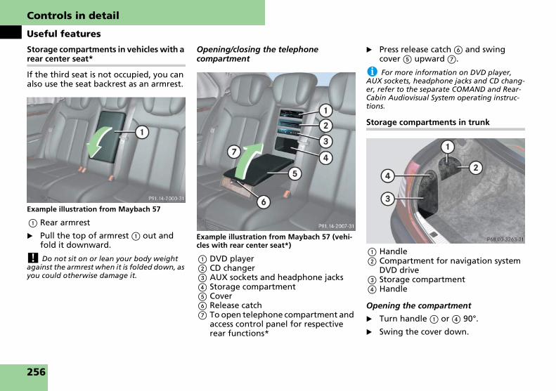
Controls in detail
Useful features
Storage compartments in vehicles with a rear center seat*
If the third seat is not occupied, you can also use the seat backrest as an armrest.
Example illustration from Maybach 57
1 Rear armrest
� Pull the top of armrest 1 out and fold it downward.
! Do not sit on or lean your body weight against the armrest when it is folded down, as you could otherwise damage it.
Opening/closing the telephone compartment
Example illustration from Maybach 57 (vehi-cles with rear center seat*)
1 DVD player2 CD changer 3 AUX sockets and headphone jacks4 Storage compartment5 Cover6 Release catch7 To open telephone compartment and
access control panel for respective rear functions*
� Press release catch 6 and swing cover 5 upward 7.
i For more information on DVD player, AUX sockets, headphone jacks and CD chang-er, refer to the separate COMAND and Rear-Cabin Audiovisual System operating instruc-tions.
Storage compartments in trunk
1 Handle2 Compartment for navigation system
DVD drive3 Storage compartment4 Handle
Opening the compartment
� Turn handle 1 or 4 90°.
� Swing the cover down.
256

Controls in detail
Useful features
Closing the compartment
� Swing the cover up.
� Turn handle 1 or 4 90°.
An umbrella is located in the trunk.
1 Umbrella2 Straps
� Use straps 2 on the inside of the trunk lid to store and secure umbrella 1.
1 Eyelet2 Retainer pin
i Installing and removing for the front seats:To install or remove the floormat more easily, move the driver’s seat or front passenger seat as far to the rear as possible (� page 63).
Installing and removing in the rear:To install or remove the floormat more easily, move the driver’s seat or front passenger seat as far to the front as possible (� page 63).
Removing
� Pull floormats off of retainer pins 2.
� Remove the floormats.
Installing
� Lay down the floormat.
� Press the floormat eyelets 1 onto re-tainer pins 2.
Umbrella
FloormatsWarning! G
Whenever you are using floormats, make sure there is enough clearance and that the floormats are securely fastened.
Floormats should always be securely fas-tened using eyelets 1 and retainer pins 2.
Before driving off, check that the floor-mats are securely in place and adjust them if necessary. A loose floormat could slip and hinder proper functioning of the ped-als.
Do not place several floormats on top of each other as this may impair pedal move-ment.
257

Controls in detail
Useful features
Cup holders, cockpit
1 Cup holder, left2 Cup holder, right
Opening
� Press the chrome label on the cover.
The compartment opens.
� Press the chrome label of the desired cup holder.
The cup holder slides out.
Closing
� Remove cup from holder.
� Push the cup holder in until it engag-es.
� Press the cover closed.
The cover engages automatically.
Rear cup/bottle holders
1 Rear cup holder2 Release catch for champagne flute/
bottle holder3 Release catch for cup holder
Opening
� Press release catch on cup holder 3.
The cup holder slides out automati-cally.
Closing
� Remove cup from holder.
� Take the cups out of the holder.
� Press the holder back in until it en-gages.
Cup holders
Warning! G
In order to help prevent spilling liquids on vehicle occupants and/or vehicle equip-ment, only use containers that fit into the cup holder. Use lids on open containers and do not fill containers to a height where the contents, especially hot liquids, could spill during braking, vehicle maneu-vers, or in an accident. Liquids spilled on vehicle occupants may cause serious per-sonal injury. Liquids spilled on vehicle equipment may cause damage not covered by the Maybach Limited Warranty.
When not in use, keep the cup holder closed. An open cup holder may cause inju-ry to you or others when contacted during braking, vehicle maneuvers, or in an acci-dent.
Keep in mind that objects placed in the cup holder may come loose during braking, ve-hicle maneuvers, or in an accident and be thrown around in the vehicle interior. Ob-jects thrown around in the vehicle interior may cause an accident and/or serious per-sonal injury.
258

Controls in detail
Useful features
Cup holder (vehicles with a rear center seat*)
1 Cup holder, right2 Cup holder, left
Opening
� Press the label of the desired cup holder.
The cup holder slides out.
Closing
� Remove cup from holder.
� Push the cup holder in until it engag-es.
Champagne flute/bottle holder
Opening
� Press release catch on champagne flute/bottle holder 2 (� page 258).
The champagne flute/bottle holder slides out automatically.
� Take the drip tray out of the opening for the bottle and place it under the opening on the carpet.
Magnets hold the drip tray in the cor-rect position.
Warning! G
When not in use, keep the champagne flute/bottle holder closed while the vehicle is in motion.
Place only champagne flutes from the Maybach Accessory range into the cham-pagne flute holder. Only use those flutes designed for use with the holder. Make sure the champagne flutes are held in place by the retaining clips whenever the flutes are placed in the holder. This will re-duce the risk of the flutes becoming loose during vehicle maneuvers.
Place only bottles that fit fully within the bottle holder to reduce the possibility of the bottle becoming loose and being thrown around in the vehicle interior dur-ing vehicle maneuvers.
Loose objects being thrown around in the vehicle during vehicle maneuvers may cause an accident and/or serious personal injury.
Warning! G
Always obey applicable state or province laws regarding passengers consuming al-coholic beverages in the vehicle and/or car-rying alcoholic beverages in the vehicle interior.
259

Controls in detail
Useful features
Inserting champagne flutes
i Use the champagne flutes from the Maybach Accessory range. Only those flutes are designed for use with the holder.
Example illustration from Maybach 57
� Place the champagne flutes in the re-tainers and press them down lightly.
The champagne flutes are held in place by the retaining clips.
� To remove the champagne flutes, pull them upright carefully.
Closing
� Take the champagne flutes/bottle out of the holder.
� With the champagne flute/bottle holder open, remove the drip tray from the transmission tunnel and place it in the opening for the bottle.
Press the holder closed until it engag-es.
Center console ashtray
1 Sliding button2 Insert slides out
Opening ashtray
� Tap lightly on the chrome label on the cover.
The ashtray opens automatically.
Removing ashtray insert
� Push sliding button 1 to the right.
The ashtray is disengaged and slides a short way out 2.
� Remove insert from ashtray frame.
Reinstalling the ashtray insert
� Install insert by pushing back into frame until it engages again.
� Close the ashtray.
Ashtrays
Warning! G
Remove front ashtray only with vehicle standing still. Set the parking brake to se-cure vehicle from movement. Move gear selector lever to position P. With gear se-lector lever in position P, turn off the en-gine.
260

Controls in detail
Useful features
Rear compartment ashtray
1 Sliding button2 Insert slides out
Opening ashtray
� Tap lightly on the chrome label on the cover.
The ashtray opens automatically.
Removing ashtray insert
� Push sliding button 1 to the right.
The ashtray is disengaged and slides a short way out 2.
Reinstalling the ashtray insert
� Install insert by pushing back into frame until it engages again.
� Close the ashtray.
Rear compartment ashtray (vehicles with a rear center seat*)
1 Lid2 Sliding button3 Ashtray lid4 Insert
Opening ashtray
� Lift lid 1 up.
� Lift ashtray lid 3.
Removing ashtray insert
� Lift lid 1 up.
� Lift ashtray lid 3.
� Press sliding button 2 forward.
Insert 4 slides out a short distance.
� Remove insert 4 from ashtray frame.
Reinstalling the ashtray insert
� Install insert 4 by pushing back into frame until it engages again.
� Close the ashtray.
261
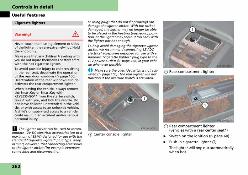
Controls in detail
Useful features
! The lighter socket can be used to accom-modate 12V DC electrical accessories (up to a maximum of 85 W) designed for use with the standard “cigarette lighter” plug type. Keep in mind, however, that connecting accessories to the lighter socket (for example extensive connecting and disconnecting,
or using plugs that do not fit properly) can damage the lighter socket. With the socket damaged, the lighter may no longer be able to be placed in the heating (pushed-in) posi-tion, or the lighter may pop out too early with the lighter not hot enough.
To help avoid damaging the cigarette lighter socket, we recommend connecting 12V DC electrical accessories designed for use with a standard “cigarette lighter” plug type to the 12V power outlets (� page 266) in your vehi-cle whenever possible.
i Make sure the override switch is not acti-vated (� page 100). The rear lighter will not function if the override switch is activated.
1 Center console lighter
1 Rear compartment lighter
1 Rear compartment lighter (vehicles with a rear center seat*)
� Switch on the ignition (� page 60).
� Push in cigarette lighter 1.
The lighter will pop out automatically when hot.
Cigarette lighters
Warning! G
Never touch the heating element or sides of the lighter; they are extremely hot. Hold the knob only.
Make sure that any children traveling with you do not injure themselves or start a fire with the hot cigarette lighter.
To avoid possible injury to children sitting in the rear seat, deactivate the operation of the rear door windows (� page 100). Deactivation of the rear windows also de-activates the rear compartment lighter.
When leaving the vehicle, always remove the SmartKey or SmartKey with KEYLESS-GO** from the starter switch, take it with you, and lock the vehicle. Do not leave children unattended in the vehi-cle, or with access to an unlocked vehicle. A child’s unsupervised access to a vehicle could result in an accident and/or serious personal injury.
262

Controls in detail
Useful features
Storage compartment in front center console
1 Storage compartment2 Chrome label
� Tap lightly on chrome label 2 on the cover.
Storage compartment 1 opens.
Storage compartment in rear center con-sole
1 Storage compartment2 Chrome label
� Tap lightly on chrome label 2 on the cover.
Storage compartment 1 opens.
Non-smokers package* Folding table* (standard on Maybach 62; optional on Maybach 57)
Warning! G
Keep the folding table closed while the ve-hicle is in motion. Otherwise, you could be injured by the table or by objects flying off the table during
� braking
� vehicle maneuvers or
� an accident.
Always fold the rear center armrest 1 downward while the vehicle is in motion. Without the armrest 1 folded down, the rear center armrest could open the storage compartment in an accident or during abrupt vehicle maneuvers. Objects stored there then could be thrown around in the vehicle interior and cause vehicle damage and/or personal injury.
263

Controls in detail
Useful features
Opening the folding table
1 To raise the armrest2 Loop3 Folding table
� Lift up armrest 1.
� Pull up folding table 3 vertically, us-ing loop 2.
4 To pull out the table5 To swing the table to the side6 Table
� Pull table 6 out vertically 4.
� Swing the table to the side 5.
� Lower armrest 1.
7 Fold out table half8 Table half9 Move table surface fore and afta Tilt table surface
� Fold out table half 8 from 7.
� Press button 9 and adjust the table fore or aft to the desired position.
� Press button a to adjust the table surface tilt. When you have obtained the desired tilt, release the button.
264

Controls in detail
Useful features
Closing the folding table
� Fold the table halves together.
� Swing the table upward vertically.
� Press the table until it engages at the base of the folding table.
� If necessary, lift up the armrest.
� Swing the folding table back com-pletely.
� Lower the armrest.
! In especially humid regions, water can condense inside the refrigerator. For this rea-son, wipe out the refrigerator regularly. For more information on vehicle care (� page 342).
i The refrigerator continues to operate for up to 2 hours after the ignition has been switched off. If the on-board voltage falls be-low the minimum level, the refrigerator will be turned off automatically.
Therefore, do not leave any perishable goods in the refrigerator.
Do not leave any open groceries in the refrig-erator.
1 To release the cover2 To open the refrigerator3 Refrigerator
Opening the refrigerator
� Lift up the rear center armrest up-ward.
� Reach into the opening and lift up re-lease catch 1.
� Open cover 2.
Refrigerator control
4 Control knob5 To increase cooling6 To decrease cooling7 To turn off the refrigerator
Turning refrigerator on
� Turn knob 4 from OFF position 7 clockwise.
The refrigerator is on.
Turning refrigerator off
� Turn knob 4 counterclockwise to OFF position 7. Make sure the rotary control is turned fully counterclock-wise, until an audible “click” is heard.
Refrigerator** in rear center console
Warning! G
Always fold the rear center armrest down-ward while the vehicle is in motion. With-out the armrest folded down, the rear center armrest could open the storage compartment in an accident or during abrupt vehicle maneuvers. Objects stored there then could be thrown around in the vehicle interior and cause vehicle damage and/or personal injury.
265

Controls in detail
Useful features
Regulating the temperature
� Turn knob 4 to the desired position.
! When setting max. cooling, the tempera-ture in the refrigerator may fall below freez-ing point. Objects stored in the refrigerator such as water bottles may burst.
Closing the refrigerator
� Press the lid down until it engages.
1 Socket in the rear center console
1 Socket in the rear center console (vehicles with a rear center seat*)
1 Socket in the trunk
1 Socket in the front passenger foot-well (vehicles with non-smokers pack-age*)
The power outlet can be used to accom-modate 12V DC electrical accessories (e.g. air pump, auxiliary lamps) up to a maximum of 180 W.
� Switch on the ignition (� page 60).
� Flip up cover.
i Make sure the override switch is not acti-vated (� page 100). The socket in the rear center console will not function if the override switch is activated.
! Make sure no fluids come into contact with the socket, as this could cause a short cir-cuit.
Power outlets
266

Controls in detail
Useful features
The vehicle is equipped with a battery charge socket. The socket allows for the connection of the Maybach battery charger* designed to charge the vehicle consumer battery or to maintain the ex-isting charge in the vehicle consumer battery while the vehicle is parked and not being driven for long periods of time (on average approximately 3 weeks or more). Not driving the vehicle for such extended periods of time may cause the charge in the vehicle batteries to drop.
The socket is located in the storage com-partment on the left side of the trunk. Only the Maybach battery charger* should be connected to this socket.
1 Handle2 Battery charge socket3 Storage compartment
� Turn handle 1 90°.
� Swing the cover down.
� Connect the Maybach battery charg-er* to battery charge socket 2. Fol-low the separate operating instructions for the Maybach battery charger*.
i You can obtain the Maybach battery charger* at any authorized Maybach Studio. Check with an authorized Maybach Studio for availability.
i If the battery for electrical consumers is deeply discharged, it may take up to approxi-mately 20 hours for the battery to be charged using the Maybach battery charger*.
If faster charging is required, a standard bat-tery charger may be needed. Using a standard battery charger will require that you discon-nect and remove the battery for electrical con-sumers. For more information, see “Practical hints” (� page 417).
The driver’s button is in the lower part of the front center console under the cover for the cup holders. Depending on vehi-cle equipment configuration, the button in the rear is either in the center console or in the top of the center armrest.
Operating from the cockpit
Button in cockpit
1 To close the curtain2 To open the curtain
Closing the curtain
� Briefly press button 1.
The curtain closes automatically.
� To stop the procedure, press the but-ton again.
Battery charge socket Rear window curtain
267

Controls in detail
Useful features
Opening the curtain
� Briefly press button 2.
The curtain opens automatically.
� To stop the procedure, press the but-ton again.
Operating from the rear
Rear button (only Maybach 57 without rear door window curtains*)
1 To close/open the curtain
Rear button (only Maybach 57 without rear door window curtains* and with rear seat*)
1 To close/open the curtain
Closing the curtain
� Briefly press button 1.
The curtain closes automatically.
� To stop the procedure, press the but-ton again.
Opening the curtain
� Briefly press button 1.
The curtain opens automatically.
� To stop the procedure, press the but-ton again.
Rear button (example illustration from vehi-cles with rear door window curtains*)
1 To close the curtain2 To open the curtain
� Open the storage compartment in the rear center armrest (� page 255).
268

Controls in detail
Useful features
Rear button (example illustration from vehi-cles with rear door window curtains* and with rear center seat*)
1 To close the curtain2 To open the curtain
� Open the storage compartment in the rear center armrest (� page 256).
Closing the curtain
� Lightly press button 1 to resistance point.
The curtain will close until you re-lease the button.
Opening the curtain
� Lightly press button 2 to resistance point.
The curtain will open until you re-lease the button.
Fully closing the curtain (Express-close)
� Press button 1 past the resistance point and release.
The curtain closes completely.
� To stop the procedure, press the but-ton again.
Fully opening the curtain (Express-open)
� Press button 2 past the resistance point and release.
The curtain opens completely.
� To stop the procedure, press the but-ton again.
The driver’s switches are in the lower part of the front center console under the cover for the cup holders. Depending on equipment, the button in the rear is either in the center console or in the top of the center armrest.
Operating from the cockpit
Button in cockpit
1 To close the curtain2 To open the curtain3 Button for rear left door window cur-
tain4 Button for rear right door window
curtain
i If you open a rear door window without rear door window curtain completely open, the curtain will open first.
Closing the curtain
� Briefly press upper part 1 of button 3 or 4.
The respective curtain closes.
� To stop the procedure, press the but-ton again.
Rear door window curtains*
269

Controls in detail
Useful features
Opening the curtain
� Briefly press lower part 2 of button 3 or 4.
The respective curtain opens.
� To stop the procedure, press the but-ton again.
Operating from the rear
Rear button
1 To close the curtain2 To open the curtain3 Button for rear left door window cur-
tain4 Button for rear right door window
curtain
� Open the storage compartment in the rear center armrest (� page 255).
Rear button (vehicles with rear center seat*)
1 To close the curtain2 To open the curtain3 Button for rear left door window cur-
tain4 Button for rear right door window
curtain
� Open the storage compartment in the rear center armrest (� page 256).
Warning! G
When operating the curtains, make sure there is no danger of anyone being harmed by the opening or closing proce-dure.
The opening or closing procedure can be immediately halted by pressing the respec-tive button again.
When leaving the vehicle, always remove the SmartKey or SmartKey with KEYLESS-GO** from the starter switch, take it with you, and lock the vehicle. Do not leave children unattended in the vehi-cle, or with access to an unlocked vehicle. A child’s unsupervised access to a vehicle could result in an accident and/or serious personal injury.
270

Controls in detail
Useful features
Closing the curtain
� Lightly press upper part 1 of button 3 or 4 to resistance point.
The respective curtain will close until you release the button.
Opening the curtain
� Lightly press lower part 2 of button 3 or 4 to resistance point.
The respective curtain will open until you release the button.
Fully closing the curtain (Express-close)
� Press upper part 1 of button 3 or 4 past the resistance point and release.
The curtain closes completely.
� To stop the procedure, press the but-ton again.
Fully opening the curtain (Express-open)
� Press lower part 2 of button 3 or 4 past the point of resistance and re-lease.
The curtain opens completely.
� To stop the procedure, press the but-ton again.
Operating the partitionWarning! G
When operating the curtains, make sure there is no danger of anyone being harmed by the opening or closing proce-dure.
The opening or closing procedure can be immediately halted by releasing the re-spective button or, if button was pressed past the resistance point and released, by pressing the respective button 3 or 4 again.
When leaving the vehicle, always remove the SmartKey or SmartKey with KEYLESS-GO** from the starter switch, take it with you, and lock the vehicle. Do not leave children unattended in the vehi-cle, or with access to an unlocked vehicle. A child’s unsupervised access to a vehicle could result in an accident and/or serious personal injury.
Partition*
Warning! G
When operating the partition, make sure there is no danger of anyone being harmed by the opening or closing proce-dure.
The opening or closing procedure can be immediately halted by releasing the but-ton or, if the button was pressed past the resistance point and released, by pressing the respective button again.
When leaving the vehicle, always remove the SmartKey or SmartKey with KEYLESS-GO** from the starter switch, take it with you, and lock the vehicle. Do not leave children unattended in the vehi-cle, or with access to an unlocked vehicle. A child’s unsupervised access to a vehicle could result in an accident and/or serious personal injury.
271

Controls in detail
Useful features
Button in cockpit
1 To close the partition2 To open the partition
i Closing the partition from the rear is not possible if you activate the override switch (� page 100).
Button in rear passenger compartment
1 To close the partition2 To open the partition
� Open the storage compartment in the rear center armrest (� page 255).
Button in rear passenger compartment (vehicles with rear center seat*)
1 To close the partition2 To open the partition
� Open the storage compartment in the rear center armrest (� page 256).
272

Controls in detail
Useful features
Closing the partition
� Lightly press button 1 to resistance point.
The partition will close until you re-lease the button.
Opening the partition
� Lightly press button 2 to resistance point.
The partition will open until you re-lease the button.
Fully closing the partition (Express-close)
� Press button 1 past the resistance point and release.
The partition closes completely.
� To stop the procedure, press the but-ton again.
Fully opening the partition (Express-open)
� Press button 2 past the point of re-sistance and release.
The partition opens completely.
� To stop the procedure, press the but-ton again.
Operating the partition curtain
Button in cockpit
1 To close the curtain2 To open the curtain
Button in rear passenger compartment
1 To close the curtain2 To open the curtain
� Open the storage compartment in the rear center armrest (� page 255).
Warning! G
When operating the curtains, make sure there is no danger of anyone being harmed by the opening or closing proce-dure.
The opening or closing procedure can be immediately halted by releasing the but-ton or, if the button was pressed past the resistance point and released, by pressing the respective button again.
When leaving the vehicle, always remove the SmartKey or SmartKey with KEYLESS-GO** from the starter switch, take it with you, and lock the vehicle. Do not leave children unattended in the vehi-cle, or with access to an unlocked vehicle. A child’s unsupervised access to a vehicle could result in an accident and/or serious personal injury.
273
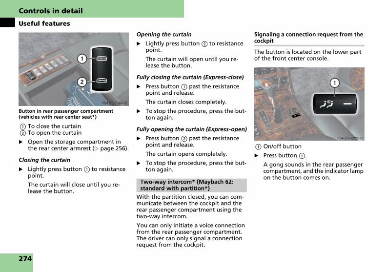
Controls in detail
Useful features
Button in rear passenger compartment (vehicles with rear center seat*)
1 To close the curtain2 To open the curtain
� Open the storage compartment in the rear center armrest (� page 256).
Closing the curtain
� Lightly press button 1 to resistance point.
The curtain will close until you re-lease the button.
Opening the curtain
� Lightly press button 2 to resistance point.
The curtain will open until you re-lease the button.
Fully closing the curtain (Express-close)
� Press button 1 past the resistance point and release.
The curtain closes completely.
� To stop the procedure, press the but-ton again.
Fully opening the curtain (Express-open)
� Press button 2 past the resistance point and release.
The curtain opens completely.
� To stop the procedure, press the but-ton again.
With the partition closed, you can com-municate between the cockpit and the rear passenger compartment using the two-way intercom.
You can only initiate a voice connection from the rear passenger compartment. The driver can only signal a connection request from the cockpit.
Signaling a connection request from the cockpit
The button is located on the lower part of the front center console.
1 On/off button
� Press button 1.
A gong sounds in the rear passenger compartment, and the indicator lamp on the button comes on.
Two-way intercom* (Maybach 62: standard with partition*)
274

Controls in detail
Useful features
Initiating a voice connection from the rear
In Maybach 62 with a rear center seat* in the storage compartment/drawer in rear center console the buttons are on the rear center console.
1 Volume control2 Speak button
In Maybach 62 with a rear center seat* the buttons are in the storage compart-ment/drawer in the rear center console.
Maybach 62 with rear center seat*
1 Volume control2 Speak button
� Press button 2.
A gong sounds in the cockpit, and a voice connection is established be-tween the cockpit and the rear pas-senger compartment.
Adjusting the volume
� Turn thumbwheel 1 until the de-sired volume has been set.
Ending the voice connection
� Press button 2 again in the rear pas-senger compartment.
275

Controls in detail
Useful features
With the communication system, you can communicate with persons outside the vehicle over a loudspeaker and an out-side microphone, without having to open a door or window.
1 Speak button for inside microphone2 Volume control3 Loudspeaker for outside microphone4 Inside microphone5 Microphone switch-over
� Take the control unit out of the glove box.
Listening
� Push microphone switch-over 5 downward.
You will hear what is being said out-side of the vehicle.
Speaking
� Press speak button 1 and keep it pressed.
You can speak as long as you keep button 1 pressed.
� Adjust volume with the volume con-trol button 2.
The steering wheel heating warms up the leather area of the steering wheel.
The stalk is located on the lower left-hand side of the steering wheel.
1 Switching on2 Indicator lamp3 Switching off
External communication (special order equipment)
Heated steering wheel
276

Controls in detail
Useful features
Switching on
� Switch on the ignition (� page 60).
� Turn switch at the tip of stalk in direc-tion of arrow 1.
The steering wheel is heated. Indica-tor lamp 2 comes on.
i The steering wheel heating is temporarily suspended while indicator lamp 2 remains on when
� the temperature of the vehicle interior is above 86°F (30°C)
� the temperature of the steering wheel is above 79°F (26°C)
When these conditions do not apply anymore, steering wheel heating continues.
Switching off
� Turn switch at the tip of stalk in direc-tion of arrow 3.
The steering wheel heating is switched off. Indicator lamp 2 goes out.
i Indicator lamp 2 flashes or switches off
� in case of power surge or undervoltage
� in case of a steering wheel heating mal-function
i The steering wheel heating switches off automatically when you remove the SmartKey from the starter switch or, on vehicles with KEYLESS-GO**, when you switch off the igni-tion (� page 60) and open the driver’s door.
For information on the steering wheel, see “Steering wheel” (� page 64).
Radio transmitters, such as a portable telephone or a citizens band unit, should only be used inside the vehicle if they are connected to an antenna that is installed on the outside of the vehicle.
The external antenna must be approved
for Maybach vehicles. Please contact an authorized Maybach Studio for informa-tion on the installation of an approved external antenna. Refer to the radio transmitter operation instructions re-garding use of an external antenna.
Telephone
Warning! G
Never operate radio transmitters equipped with a built-in or attached antenna (i.e. without being connected to an exter-nal antenna) from inside the vehicle while the engine is running. Doing so could lead to a malfunction of the vehicle’s electronic system, possibly resulting in an accident and/or serious personal injury.
Warning! G
Please do not forget that your primary re-sponsibility is to drive the vehicle. A driv-er’s attention to the road must always be his/her primary focus when driving. For your safety and the safety of others, we recommend that you pull over to a safe lo-cation and stop before placing or taking a telephone call.
If you choose to use the telephone1 while driving, please use the hands-free device and only use the telephone when road, weather and traffic conditions permit. Some jurisdictions prohibit the driver from using a mobile telephone while driving a vehicle.
Only operate the COMAND (Cockpit Man-agement and Data System)1 if road, weather and traffic conditions permit.
Bear in mind that at a speed of just 30 mph (approximately 50 km/h), your vehicle is covering a distance of 44 feet (approxi-mately 14 m) every second.
1 Observe all legal requirements.
277

Controls in detail
Useful features
You can receive and place telephone calls using the s and t buttons on the steering wheel. To carry out other telephone functions, use the control sys-tem (� page 164).
See the separate operating manual COMAND and Rear-Cabin Audiovisual System for instructions on how to use the telephone.
Mobile phone in the front
Mobile phone cradles for GSM or CDMA phones can be installed in the cockpit. These mobile phone cradles can be ob-tained from an authorized Maybach Studio.
The functions and services available to you while using the mobile phone de-pend on your service provider and the type of mobile phone you are using.
1 Compartment lid release button2 Compartment lid
Opening
� Press release button 1.
Compartment lid 2 opens down-ward. The telephone handset swings out.
Closing
� Press button 1 to close.
! To prevent any damage, the mobile phone flap must be folded down before clos-ing the telephone compartment.
i The Roadside Assistance button • and the Information button ¡ (� page 285) are located in the compartment for the front tele-phone.
Inserting the mobile phone in the mobile phone cradle
Once the mobile phone has been insert-ed in the mobile phone cradle, calls can only be made via the hands-free system.
! Do not try to remove the mobile phone along with the cradle. You could otherwise damage the mobile phone cradle.
� Remove the cover for the external an-tenna connection from the back of the mobile phone and store it in a safe place.
1 Insert the mobile phone2 Connector contact3 Mobile phone cradle
Warning! G
Always keep the compartment for the front telephone closed while the vehicle is in motion. The protruding telephone could otherwise cause injury to you and others during
� braking
� vehicle maneuvers or
� an accident.
278

Controls in detail
Useful features
� Slide the lower end of the mobile phone into connector contact 2 on cradle 3.
� Push the top of the mobile phone in direction of arrow 1, until the lug on the mobile phone release button en-gages.
The mobile phone is connected to the network via the external antenna.
The mobile phone is linked to the hands-free device and the multifunc-tion steering wheel.
The battery is charged depending on its charge status and the position of the key in the ignition switch. The charge procedure will be indicated in the mobile phone’s display.
i GSM mobile phone:The phone books contained on the SIM card and in the mobile phone’s memory will be im-ported. If an identical entry has been stored in both phone books, the entry will appear twice in the multifunction display.
You can place or receive phone calls us-ing the t and s buttons in the steering wheel. You can control other functions of the mobile phone via the control system (� page 164).
i When you take the SmartKey or SmartKey with KEYLESS-GO** out of the starter switch, the mobile phone remains switched on for ap-proximately 10 minutes (run-on time). If you place or receive a call during this time, the mo-bile phone switches off 10 minutes after the call has been completed.
Removing the mobile phone from the cradle
1 Release catch for mobile phone2 Mobile phone cradle
� Press release catch in direction of arrow 1 and take mobile phone out of mobile phone cradle 2.
Changing the mobile phone cradle
Please contact an authorized Maybach Studio if you require a different mobile phone cradle for your GSM or CDMA mo-bile phone.
Removing an existing mobile phone cra-dle:
1 To release the mobile phone cradle2 To remove the mobile phone cradle3 Mobile phone cradle
� Press release button in direction of arrow 1 and take mobile phone cradle 3 out in direction of arrow 2.
279

Controls in detail
Useful features
Installing a different mobile phone cra-dle:
1 Contact plate2 Recesses3 Mobile phone cradle
� Insert mobile phone cradle 3 into recesses 2 of contact plate 1.
� Push mobile phone cradle 3 forward until it engages.
Mobile phone in the rear
Your vehicle is equipped with Bluetooth®. The Bluetooth® interface is located in the rear armrest.
� Open the storage compartment in the rear center armrest (� page 255).
Inserting the Bluetooth® interface into cradle
1 Insert the Bluetooth® interface2 Contact3 Cradle
� Slide the lower end of the Bluetooth® interface into contact 2 on cradle 3.
4 Engage the Bluetooth® interface into cradle
5 Release button6 Button with indicator lamp
� Push the top of the Bluetooth® inter-face in direction of arrow 4, until the release button 5 engages.
The indicator lamp in the button 6 will flash slowly in blue, to indicate that the interface is ready for pairing with a Bluetooth® compatible mobile phone.
280

Controls in detail
Useful features
Initializing pairing of Bluetooth® inter-face and mobile phone
1 Button with indicator lamp
� To initialize pairing, press and hold button 1 on the Bluetooth® inter-face until the indicator lamp in the button begins to flash rapidly in blue.
� Depending on which Bluetooth® ca-pable mobile phone you have, con-duct a search for “devices within range”, until you find the Bluetooth® interface with the symbol “MB BTUM”.
� Select this symbol.
� Enter “0000” (four zeros), when prompted to enter the passkey.
The indicator lamp in the button 1 will stop flashing and remain illumi-nated in blue.
The pairing of the Bluetooth® inter-face with your mobile phone was suc-cessful.
i Pairing is only required once for each handset.
You will be able to make and receive hands-free phone calls using the speak-ers and microphones installed in your ve-hicle.
You can also switch from hands-free mode to privacy phone mode.
i Please contact an authorized Maybach Studio for the most recent list of Bluetooth® capable mobile phones that have been ap-proved for use in your vehicle.
For detailed instructions on how to pair the Bluetooth® interface with the mobile phone, please refer to the mobile phone operating instructions.
! The initial activation of the Tele Aid sys-tem may only be performed by completing the subscriber agreement and placing an ac-quaintance call using the Information button ¡, located in the phone compart-ment to the left of the glove box. Failure to complete either of these steps will result in a system that is not activated.
If you have any questions regarding activa-tion, please call the Maybach Assistance Cen-ter at 1-866-FOR-MAYBach (in the USA) or 1-888-881-6611 (in Canada).
The Tele Aid system
(Telematic Alarm Identification on Demand)
The Tele Aid system consists of three types of response:
� automatic and manual emergency
� Roadside Assistance and
� information
The Tele Aid system is operational pro-viding that the vehicle’s battery is charged, properly connected, not dam-aged and cellular and GPS coverage is available.
Tele Aid
281

Controls in detail
Useful features
The speaker volume of a Tele Aid call can be adjusted when using the volume con-trol on the multifunction steering wheel or the volume control on the COMAND. To raise, press button æ and to lower, press button ç on the steering wheel or use the volume knob on your COMAND head unit.
� To activate, press one of the SOS but-tons, the Roadside Assistance button • or the Information button ¡, depending on the type of response required.
i The SOS button is located in the overhead control panel (� page 284). An additional SOS button is located in the middle armrest of the rear seat or, in Maybach 62 vehicles with rear center seat* and partition* or two-way inter-com*, in the storage compartment/drawer in rear center console.
The Roadside Assistance button • and the Information button ¡ are located in the front telephone compartment (� page 286).
Shortly after the completion of your Tele Aid acquaintance call, you will re-ceive a user ID and password.
i The Tele Aid system utilizes the cellular network for communication and the GPS (Glo-bal Positioning System) satellites for vehicle location. If either of these signals are unavail-able, the Tele Aid system may not function and if this occurs, assistance must be sum-moned by other means.
System self-check
Initially, after switching on the ignition, malfunctions are detected and indicated (the indicator lamps in the SOS button, the Roadside Assistance button • and the Information button ¡ stay on longer than 10 seconds or do not come on). The message
TELE AIDINOPERATIVE
appears for approximately 10 seconds in the multifunction display.
Warning! G
Bear in mind that at a speed of just 30 mph (approximately 50 km/h), your vehicle is covering a distance of 44 feet (approxi-mately 14 m) every second.
Warning! G
If the indicator lamps in the SOS button, in the Roadside Assistance button • and/or in the Information button ¡ do not come on during the system self-check or if any of these indicators remain illuminated constantly in red and/or the message
TELE AIDINOPERATIVEis displayed in the multifunction display af-ter the system self-check, a malfunction in the system has been detected.
If a malfunction is indicated as outlined above, the system may not operate as ex-pected. Have the system checked at the nearest authorized Maybach Studio as soon as possible.
282

Controls in detail
Useful features
Emergency calls
An emergency call is initiated automati-cally following an accident in which the emergency tensioning devices (ETDs) or airbags deploy.
An emergency call can also be initiated manually by opening the cover in the overhead control panel labeled SOS, then briefly pressing the button located under the cover. An additional SOS but-ton is located in the middle armrest of the rear seat or, in Maybach 62 vehicles with rear center seat* and partition* or with rear center seat* and two-way in-tercom*, in the storage compartment/drawer in rear center console.
For instructions on initiating an emer-gency call manually (� page 284).
Once the emergency call is in progress, the indicator lamp in the SOS button will begin to flash. The message CONNECTING CALL appears in the multifunction dis-play.
When the connection is established, the message CALL CONNECTED appears in the multifunction display.
All information relevant to the emergen-cy, such as the location of the vehicle (de-termined by the GPS satellite location system), vehicle model, identification number and color are generated.
A voice connection between the Re-sponse Center and the occupants of the vehicle will be established automatically soon after the emergency call has been initiated. The Response Center will at-tempt to determine more precisely the nature of the emergency provided they can speak to an occupant of the vehicle.
The Tele Aid system is available if:
� it has been activated and is opera-tional. Activation requires a subscrip-tion for monitoring services, connection and cellular air time.
� the relevant cellular phone network and GPS signals are available and pass the information on to the Response Center.
i Location of the vehicle on a map is only possible if the vehicle is able to receive signals from the GPS satellite network and pass the information on to the Response Center.
Warning! G
If the indicator lamp in the SOS button is il-luminated continuously and there was no voice connection to the Response Center established, then the Tele Aid system could not initiate an emergency call (e.g. the rel-evant cellular phone network is not avail-able). The message CALL FAILED appears in the multifunction display for approximate-ly 10 seconds.
Should this occur, assistance must be sum-moned by other means.
283

Controls in detail
Useful features
Initiating an emergency call manually
SOS button in the overhead control panel
1 Cover2 SOS button
SOS button in the rear center console
1 Cover2 SOS button
For Maybach 57 with rear center seat*: the additional SOS button is located in the rear center console.
SOS button* in the rear center console
1 Cover2 SOS button
284

Controls in detail
Useful features
For Maybach 62 with rear center seat*: the additional SOS button is located in the storage compartment/drawer.
SOS button* in the storage compartment/drawer
1 Cover2 SOS button
� Briefly press on the cover of the emergency call button 1 with the inscription SOS.
The cover will open.
� Press SOS button 2 briefly.
The indicator lamp in SOS button 2 flashes until the emergency call is concluded.
� Wait for a voice connection to the Re-sponse Center.
� Close cover 1 after the emergency call is concluded.
Roadside Assistance button •
The Roadside Assistance button • is located in the front telephone compart-ment.
1 Compartment lid release2 Compartment lid
� Press button 1.
The compartment lid 2 opens down-ward.
Warning! G
If you feel at any way in jeopardy when in the vehicle (e.g. smoke or fire in the vehi-cle, vehicle in a dangerous road location), please do not wait for voice contact after you have pressed the emergency button. Carefully leave the vehicle and move to a safe location. The Response Center will au-tomatically contact local emergency offi-cials with the vehicle’s approximate location if they receive an automatic SOS signal and cannot make voice contact with the vehicle occupants.
285

Controls in detail
Useful features
1 Compartment lid release2 Information button ¡3 Roadside Assistance button •
� Press and hold Roadside Assistance button • (for longer than 2 seconds).
A call to a Maybach Roadside Assistance dispatcher will be initiat-ed. The button • flashes while the call is in progress. The message CONNECTING CALL will appear in the multifunction display and the audio system is muted.
When the connection is established, the message CALL CONNECTED appears in the multifunction display. The Tele Aid sys-tem will transmit data generating the ve-hicle identification number, model, color and location (subject to availability of cellular and GPS signals).
A voice connection between the Road-side Assistance dispatcher and the occu-pants of the vehicle will be established.
� Describe the nature of the need for assistance.
The Maybach Roadside Assistance dis-patcher will either dispatch a qualified Maybach technician or arrange to tow your vehicle to the nearest authorized Maybach Studio. For services such as la-bor and/or towing, charges may apply. Refer to the Roadside Assistance manual for more information.
The following is only available in the USA:
� Sign and Drive services: Services such as a jump start, a few gallons of fuel or the replacement of a flat tire with the vehicle spare tire are obtainable.
i The indicator lamp on the Roadside Assis-tance button • remains illuminated in red for approximately 10 seconds during the sys-tem self-check after switching on ignition (together with the SOS button and the Infor-mation button ¡).
See system self-check (� page 282) when the indicator lamp does not come on in red or stays on longer than approximately 10 seconds.
If the indicator lamp on the Roadside Assis-tance button • is illuminated continuously and there was no voice connection to the Re-sponse Center established, then the Tele Aid system could not initiate a Roadside Assis-tance call (e.g. the relevant cellular phone network is not available). The message CALL FAILED appears in the multifunction display.
Roadside Assistance calls can be termi-nated using the t button on the mul-tifunction steering wheel or the respective button for ending a tele-phone call on the COMAND head unit.
286

Controls in detail
Useful features
Information button ¡
The Information button ¡ is located in the front telephone compartment (� page 286).
� Press and hold Information button ¡ (for longer than 2 seconds).
A call to the Customer Assistance Center will be initiated. The button ¡ flashes while the call is in progress. The message CONNECTING CALL will appear in the multifunction display and the audio system is mut-ed.
When the connection is established, the message CALL CONNECTED appears in the multifunction display. The Tele Aid sys-tem will transmit data generating the ve-hicle identification number, model, color and location (subject to availability of cellular and GPS signals).
A voice connection between the Custom-er Assistance Center representative and the occupants of the vehicle will be es-tablished. Information regarding the op-eration of your vehicle, the nearest authorized Maybach Studio or Maybach USA products and services is available to you.
i The indicator lamp on the Information button ¡ remains illuminated in red for ap-proximately 10 seconds during the system self-check after switching on ignition (togeth-er with the SOS button and the Roadside As-sistance button •).
See system self-check (� page 282) when the indicator lamp does not come on in red or stays on longer than approximately 10 seconds.
If the indicator lamp on the Information button ¡ is illuminated continuously and there was no voice connection to the Re-sponse Center has been established, then the Tele Aid system could not initiate an Informa-tion call (e.g. the relevant cellular phone net-work is not available). The message CALL FAILED appears in the multifunction display.
Information calls can be terminated using the t button on the multifunction steering wheel or the respective button for ending a telephone call on the COMAND head unit.
! If the indicator lamps do not start flashing after pressing one of the buttons or remain il-luminated (in red) at any time, the Tele Aid system has detected a malfunction or the ser-vice is not currently active, and may not ini-tiate a call. Visit your Maybach Studio and have the system checked or contact the Maybach Assistance Center at 1-866-FOR-MAYBach (in the USA) or 1-888-881-6611 (in Canada) as soon as possi-ble.
Call priority
If other service calls such as a Roadside Assistance call or Information call are ac-tive, an Emergency call is still possible. In this case, the Emergency call will take pri-ority and override all other active calls.
i The indicator lamp in the corresponding button flashes until the call is concluded. Calls can only be terminated by a Response Center or Customer Assistance Center representative except Roadside Assistance and Information calls, which can also be terminated by pressing button t on the multifunction steering wheel or the respective button for ending a telephone call on the COMAND head unit.
! If the indicator lamp continues to flash or the system does not reset, contact the Maybach Assistance Center at 1-866-FOR-MAYBach (in the USA) or 1-888-881-6611 (in Canada).
i When a Tele Aid call has been initiated, the COMAND system audio is muted and the selected mode (radio, tape or CD) pauses. The mobile phone switches off. If it is necessary for you to use this phone, then the vehicle must be parked. Disconnect the coiled cord and place the call. The COMAND navigation sys-tem (if engaged) will continue to run. The dis-play in the instrument cluster is available for use and spoken commands are only available by pressing the button on the COMAND unit. A pop-up window will appear in the COMAND display to indicate that a Tele Aid call is in progress.
287

Controls in detail
Useful features
Remote door unlock
In case that you have locked your vehicle unintentionally (e.g. SmartKey inside ve-hicle), and the reserve SmartKey is not mobile phone:
� Contact the Maybach Assistance Cen-ter at 1-866-FOR-MAYBach (in the USA) or 1-888-881-6611 (in Canada).
You will be asked to provide your password which you provided when you completed the subscriber agree-ment.
� Then return to your vehicle and pull the trunk recessed handle for a mini-mum of 20 seconds until the SOS but-ton is flashing.
The message CALL CONNECTED appears in the multifunction display.
As an alternative, you may unlock the ve-hicle via Internet using the ID and pass-word sent to you shortly after the completion of your acquaintance call.
The Response Center will then unlock your vehicle with the remote door un-locking feature.
i The remote door unlock feature is avail-able if the relevant cellular phone network is available.
The SOS button flashes and the message CALL CONNECTED will appear in the multifunc-tion display to indicate receipt of the door un-lock command.
Once the vehicle is unlocked, a Response Cen-ter specialist will attempt to establish voice contact with the vehicle occupants.
If the trunk recessed handle was pulled for more than 20 seconds before door unlock au-thorization was received by the Response Cen-ter, you must wait 15 minutes before pulling the trunk recessed handle.
Stolen Vehicle Recovery services
In the event your vehicle was stolen:
� Report the incident to the police.
The police will issue a numbered inci-dent report.
� Pass this number on to the Maybach Response Center along with your password issued to you when you subscribed to the service.
The Response Center will then at-tempt to covertly contact the vehi-cle’s Tele Aid system. Once the vehicle is located, the Response Cen-ter will contact the local law enforce-ment and you. The vehicle’s location will only be provided to law enforce-ment.
i When the anti-theft alarm or the tow-away alarm stays on for more than 30 seconds, a call is initiated automatically to the Re-sponse Center. See anti-theft alarm system (� page 110) and tow-away alarm (� page 111).
288

Controls in detail
Useful features
The integrated remote control is capable of operating up to three separately con-trolled devices. It provides a convenient way to replace up to three hand-held re-mote controls used to operate devices such as garage door openers, gate open-ers, or other devices compatible with HomeLink® or some other systems.
Before the integrated remote control can be used, it must be programmed to the garage door opener, gate operator or other device you wish to operate. See the following instructions for program-ming information.
Interior rear view mirror with integrated re-mote control
1 Indicator lamp
2 3 4 Signal transmitter button
Needed for programming (not part of vehicle equipment):
5 Hand-held remote control of garage door opener, gate op-erator or other device
6 Hand-held remote control but-ton
Garage door openerWarning! G
Before programming the integrated re-mote control to a garage door opener or gate operator, make sure people and ob-jects are out of the way of the device to prevent potential harm or damage. When programming a garage door opener, the door moves up or down. When program-ming a gate operator, the gate opens or closes.
Do not use the integrated remote control with any garage door opener that lacks safety stop and reverse features as re-quired by U.S. federal safety standards (this includes any garage door opener model manufactured before April 1, 1982). A garage door that cannot detect an ob-ject – signaling the door to stop and re-verse – does not meet current U.S. federal safety standards.
When programming a garage door open-er, park the vehicle outside the garage.
Do not run the engine while programming the integrated remote control. Inhalation of exhaust gas is hazardous to your health. All exhaust gas contains carbon monoxide (CO), and inhaling it can cause unconsciousness and possible death.
289

Controls in detail
Useful features
Programming or reprogramming the integrated remote control
Step 1:
� Switch on the ignition (� page 60).
Step 2:
� If you have previously programmed a signal transmitter button and wish to retain its programming, proceed to step 3.
If you are programming the integrat-ed remote control for the first time, press and hold the two outer signal transmitter buttons 3 and 4 and re-lease them only when indicator lamp 1 begins to flash after approx-imately 20 seconds (do not hold the button for longer than 30 seconds). This procedure erases any previous settings for all three channels and ini-tializes the memory.
If you later wish to program a second and/or third hand-held transmitter to the remaining two signal transmitter buttons, do not repeat this step and begin directly with step 3.
Step 3:
� Hold the end of hand-held remote control 5 of the device you wish to train approximately 2 to 5 in (5 to 12 cm) away from the signal transmitter button (2, 3 or 4) to be programmed, while keeping indica-tor lamp 1 in view.
Step 4:
� Using both hands, simultaneously press hand-held remote control but-ton 6 and the desired signal trans-mitter button (2, 3 or 4). Do not release the buttons until step 5 is completed.
Indicator lamp 1 will flash, first slow-ly and then rapidly.
i Indicator lamp 1 flashes immediately the first time the signal transmitter button is pro-grammed. If this button has already been pro-grammed, the indicator lamp will only start flashing after 20 seconds.
Step 5:
� After indicator lamp 1 changes from a slow to a rapidly flashing light, re-lease the hand-held remote control button and the signal transmitter button.
Step 6:
� Press and hold the just-trained signal transmitter button (2, 3 or 4) and observe indicator lamp 1.
If indicator lamp 1 stays on constant-ly, programming is complete and your device should activate when the respective signal transmitter button (2, 3 or 4) is pressed and released.
i If indicator lamp 1 flashes rapidly for about 2 seconds and then turns to a constant light, continue with programming steps 8 through 12 as your garage door opener may be equipped with the “rolling code” feature.
Step 7:
� To program the remaining two signal transmitter buttons, repeat the steps above starting with step 3.
290

Controls in detail
Useful features
Rolling code programming
To train a garage door opener (or other rolling code devices) with the rolling code feature, follow these instructions after completing the “Programming” portion (steps 1 through 6) of this text. (A second person may make the follow-ing training procedures quicker and eas-ier.)
Step 8:
� Locate “training” button on the ga-rage door opener motor head unit.
Exact location and color of the but-ton may vary by garage door opener brand. Depending on manufacturer, the “training” button may also be re-ferred to as “learn” or “smart” but-ton. If there is difficulty locating the transmitting button, refer to the ga-rage door opener Operator’s Manual.
Step 9:
� Press the “training” button on the garage door opener motor head unit.
The “training light” is activated.
You have 30 seconds to initiate the fol-lowing two steps.
Step 10:
� Return to the vehicle and firmly press, hold for 2 seconds and release the programmed signal transmitter but-ton (2, 3 or 4).
Step 11:
� Press, hold for 2 seconds and release same signal transmitter button a sec-ond time to complete the training process.
i Some garage door openers (or other roll-ing code equipped devices) may require you to press, hold for 2 seconds and release the same signal transmitter button a third time to complete the training process.
Step 12:
� Confirm the garage door operation by pressing the programmed signal transmitter button (2, 3 or 4).
Step 13:
� To program the remaining two signal transmitter buttons, repeat the steps above starting with step 3.
Gate operator/Canadian programming
Canadian radio-frequency laws require transmitter signals to “time-out” (or quit) after several seconds of transmis-sion which may not be long enough for the integrated signal transmitter to pick up the signal during programming. Simi-lar to this Canadian law, some U.S. gate operators are designed to “time-out” in the same manner.
If you live in Canada or if you are having difficulties programming a gate opera-tor (regardless of where you live) by us-ing the programming procedures, replace step 4 with the following:
Step 4:
� Press and hold the signal transmitter button (2, 3 or 4). Do not release this button until it has been success-fully trained. ��
291

Controls in detail
Useful features
�
� While still holding down the signal transmitter button (2, 3 or 4), “cycle” your hand-held remote con-trol button 6 as follows: Press and hold button 6 for 2 seconds, then re-lease it for 2 seconds, and again press and hold it for 2 seconds. Repeat this sequence on the hand-held remote control until the frequency signal has been learned. Upon successful train-ing, indicator lamp 1 will flash slow-ly and then rapidly after several seconds.� Proceed with programming step 5 and step 6 to complete.
i Upon completion of programming the in-tegrated remote control, make sure you re-tain the hand-held remote control that came with the garage door opener, gate operator or other device. You may need it for use in other vehicles, for future programming of an integrated remote control, or simply for con-tinued use as a hand-held remote control to operate the respective device in other situa-tions.
Reprogramming a single signal transmit-ter button
To program a device using a signal trans-mitter button previously trained, follow these steps:
� Switch on the ignition (� page 60).
� Press and hold the desired signal transmitter button (2, 3 or 4). Do not release the button.
� Indicator lamp 1 will begin to flash after 20 seconds. Without releasing the signal transmitter button, pro-ceed with programming starting with step 3.
Operation of integrated remote control
� Switch on the ignition (� page 60).
� Select and press the appropriate inte-grated signal transmitter button (2, 3 or 4) to activate the remote controlled device.
The integrated remote control trans-mitter continues to send the signal as long as the button is pressed – up to 20 seconds.
Erasing the remote control memory
� Switch on the ignition (� page 60).
� Simultaneously press and hold outer signal transmitter buttons 3 and 4, for approximately 20 seconds, until indicator lamp 1 flashes rapidly. Do not hold for longer than 30 seconds.
The codes of all three channels are erased.
i If you sell your vehicle, erase the codes of all three channels.
Programming tips
If you are having difficulty programming the integrated remote control, here are some helpful tips:
� Check the frequency of the hand-held remote control 5 (typically lo-cated on the reverse side of the re-mote). The integrated remote control is compatible with radio-frequency devices operating between 280-390 MHz.
� Put a new battery in hand-held re-mote control 5. This will increase the likelihood of the hand-held remote control sending a faster and more ac-curate signal to the integrated re-mote control.
�
292
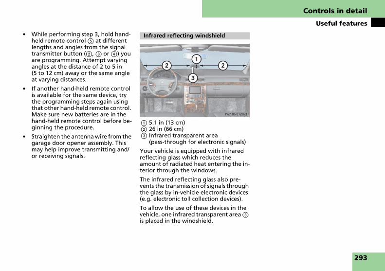
Controls in detail
Useful features
� While performing step 3, hold hand-held remote control 5 at different lengths and angles from the signal transmitter button (2, 3 or 4) you are programming. Attempt varying angles at the distance of 2 to 5 in (5 to 12 cm) away or the same angle at varying distances.
� If another hand-held remote control is available for the same device, try the programming steps again using that other hand-held remote control. Make sure new batteries are in the hand-held remote control before be-ginning the procedure.
� Straighten the antenna wire from the garage door opener assembly. This may help improve transmitting and/or receiving signals.
1 5.1 in (13 cm)2 26 in (66 cm)3 Infrared transparent area
(pass-through for electronic signals)
Your vehicle is equipped with infrared reflecting glass which reduces the amount of radiated heat entering the in-terior through the windows.
The infrared reflecting glass also pre-vents the transmission of signals through the glass by in-vehicle electronic devices (e.g. electronic toll collection devices).
To allow the use of these devices in the vehicle, one infrared transparent area 3 is placed in the windshield.
Infrared reflecting windshield
293

294

Operation
The first 1000 miles (1500 km)
Driving instructions
At the gas station
Engine compartment
Tires and wheels
Winter driving
Maintenance
Vehicle care
295

Operation
The first 1000 miles (1500 km)
In the “Operation” section, you will find detailed information on operating, maintaining and caring for your vehicle.
The more cautiously you treat your vehi-cle during the break-in period, the more satisfied you will be with its performance later on.
� Drive your vehicle during the first 1000 miles (1500 km) at varying but moderate vehicle and engine speeds.
� During this period, avoid heavy loads (full throttle driving) and excessive engine speeds (no more than 2⁄3 of maximum rpm in each gear).
� Avoid accelerating by kickdown.
� Do not attempt to slow the vehicle down by shifting to a lower gear us-ing the gear selector lever.
� Select gear positions 3, 2 or 1 only when driving at moderate speeds (for hill driving).
� Select C as the preferred shift pro-gram (� page 183) for the first 1000 miles (1500 km).
After 1000 miles (1500 km) you may gradually increase vehicle and engine speeds to the permissible maximum.
! All of the above instructions, as may apply to your vehicle type, also apply when driving the first 1000 miles (1500 km) after the en-gine or the rear differential has been re-placed.
i Always obey applicable speed limits.
The first 1000 miles (1500 km)
296

Operation
Driving instructions
Fuel consumption, to a great extent, de-pends on driving habits and operating conditions.
To save fuel you should:
� Keep tires at the recommended tire inflation pressures.
� Remove unnecessary loads.
� Allow engine to warm up under low load use.
� Avoid frequent acceleration and de-celeration.
� Have all maintenance work per-formed at the intervals specified in the Maintenance Booklet and as re-quired by the Maintenance System (U.S. vehicles) or FSS (Canada vehi-cles). Contact an authorized Maybach Studio.
Fuel consumption is also increased by driving in cold weather, in stop-and-go traffic, on short trips and in hilly area.
Driving instructions
Drive sensibly – save fuel
Drinking and driving
Warning! G
Drinking and driving and/or taking drugs and driving are very dangerous combina-tions. Even a small amount of alcohol or drugs can affect your reflexes, perceptions and judgment.
The possibility of a serious or even fatal ac-cident are greatly increased when you drink or take drugs and drive.
Do not drink or take drugs and drive or al-low anyone to drive who has been drink-ing or taking drugs.
Pedals
Warning! G
Make sure that absolutely no objects are obstructing the pedals’ range of move-ment. Keep the driver’s footwell clear of all obstacles. If there are any floormats or carpets in the footwell, make sure that the pedals still have sufficient clearance.
Power assistance
Warning! G
The electro-hydraulic brake system re-quires electrical power to operate.
A malfunction in the vehicle’s power sup-ply or electrical system may impair brake system operation and switch it into its emergency operation mode. In such a case, the red brake warning lamp (� page 360) and warning messages in the instrument cluster come on while driving (see page 380 to page 381). To brake, the driver must then apply significantly great-er brake pedal pressure and depress the pedal much further to obtain the expected braking effect. If necessary, apply full pres-sure to the brake pedal. Brakes may only be applied to the front wheels. Stopping distance is increased!
If there is a malfunction in the electro-hy-draulic brake system, we recommend that the vehicle be transported with all wheels off the ground using flatbed or appropri-ate wheel lift/dolly equipment. A tow bar must be used if circumstances do not per-mit the use of the recommended towing methods and the vehicle requires towing with all four wheels on the ground. Tow-ing the vehicle with all four wheels on the ground is only permissible for distances up to 30 miles (50 km) and at a speed not to exceed 30 mph (50 km/h). ��
297

Operation
Driving instructions
�
! Because the ESP® operates automatically, the engine and ignition must be shut off (SmartKey in starter switch position 0 or 1 or KEYLESS-GO* start/stop button in position 0 or 1) when testing the brakes on a brake test dynamometer and such testing should be no longer than 10 seconds.Active braking action through ESP® may oth-erwise seriously damage the brake system which is not covered by the Maybach Limited Warranty.
To help prevent brake disk corrosion af-ter driving on wet road surfaces (particu-larly salted roads), it is advisable to brake the vehicle with considerable force prior to parking. The heat generated serves to dry the brakes.
If your brake system is normally only sub-jected to moderate loads, you should oc-casionally test the effectiveness of the brakes by applying above-normal brak-ing pressure at higher speeds. This will also enhance the grip of the brake pads.
Refer to the description of the Brake As-sist System (BAS) (� page 104).
If the parking brake is released and the brake warning lamp in the instrument cluster stays on, the brake fluid level in the reservoir is too low.
Brake pad wear or a leak in the system may be the reason for low brake fluid level in the reservoir.
The brake fluid level in the reservoir may be too low if the brake warning lamp in the instrument cluster comes on and an acoustic warning sounds although the parking brake is released (� page 360). Observe additional messages in the mul-tifunction display that may appear (� page 381).
Have the brake system inspected imme-diately. Contact an authorized Maybach Studio.
All checks and service work on the brake system should be carried out by qualified technicians only. Contact an authorized Maybach Studio.
Only install brake pads and brake fluid recommended by us for use on Maybach vehicles.
For more information, refer to “Towing the vehicle” (� page 423).
With the engine not running, there is no power assistance for the brake and steer-ing systems. In this case, it is important to keep in mind that a considerably higher degree of effort is necessary to brake and steer the vehicle.
Brakes
Warning! G
After driving in heavy rain for some time without applying the brakes or through water deep enough to wet brake compo-nents, the first braking action may be somewhat reduced and increased pedal pressure may be necessary to obtain ex-pected braking effect. Maintain a safe dis-tance from vehicles in front.
Resting your foot on the brake pedal will cause excessive and premature wear of the brake pads.
It can also result in the brakes overheating, thereby significantly reducing their effec-tiveness. It may not be possible to stop the vehicle in a safe location in sufficient time to avoid an accident.
�
Warning! G
Make sure not to endanger any other road users when carrying out these braking ma-neuvers.
298

Operation
Driving instructions
! When driving down long and steep grades, relieve the load on the brakes by shift-ing into a lower gear to use the engine’s brak-ing power. This helps prevent overheating of the brakes and reduces brake pad wear.
After hard braking, it is advisable to drive on for some time, rather than im-mediately park the vehicle, so that the air stream can cool down the brakes fast-er.
Apply the brakes to test them briefly af-ter driving off. Perform this procedure only when the road is clear of other traf-fic.
Warm up the engine smoothly. Do not place full load on the engine until the operating temperature has been reached.
! When driving off on a slippery surface, do not allow a drive wheel to spin for an extend-ed period with the ESP® switched off. Doing so may cause serious damage to the drivetrain which is not covered by the Maybach Limited Warranty.
i Simultaneously depressing the accelera-tor pedal and applying the brake reduces en-gine performance and causes premature brake and drivetrain wear.
Warning! G
If other than recommended brake pads are installed, or other than recommended brake fluid is used, the braking properties of the vehicle can be degraded to an ex-tent that safe braking is substantially im-paired. This could result in an accident.
Driving off Parking
Warning! G
Do not park this vehicle in areas where combustible materials such as grass, hay or leaves can come into contact with the hot exhaust system, as these materials could be ignited and cause a vehicle fire.
To reduce the risk of personal injury, or damage to the vehicle drivetrain, as a re-sult of vehicle movement, before turning off the engine and leaving the vehicle al-ways:
� Keep right foot firmly on brake pedal.
� Firmly depress parking brake pedal.
� Move the gear selector lever to position P.
� Slowly release brake pedal.
� When parked on an incline, turn front wheels towards the road curb.
� Turn the SmartKey or the SmartKey with KEYLESS-GO** to starter switch position 0 and remove, or press KEYLESS-GO** start/stop button (� page 61).
� Take the SmartKey or the SmartKey with KEYLESS-GO** with you and lock vehicle when leaving.
299
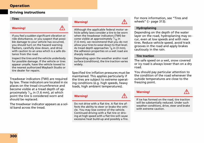
Operation
Driving instructions
Treadwear indicators (TWI) are required by law. These indicators are located in six places on the tread circumference and become visible at a tread depth of ap-proximately 1⁄16 in (1.6 mm), at which point the tire is considered worn and should be replaced.
The treadwear indicator appears as a sol-id band across the tread.
Specified tire inflation pressures must be maintained. This applies particularly if the tires are subject to extreme operat-ing conditions (e.g. high speeds, heavy loads, high ambient temperatures).
For more information, see “Tires and wheels” (� page 313).
Depending on the depth of the water layer on the road, hydroplaning may oc-cur, even at low speeds and with new tires. Reduce vehicle speed, avoid track grooves in the road and apply brakes cautiously in the rain.
The safe speed on a wet, snow covered or icy road is always lower than on a dry road.
You should pay particular attention to the condition of the road whenever the outside temperatures are close to the freezing point.
Tires
Warning! G
If you feel a sudden significant vibration or ride disturbance, or you suspect that possi-ble damage to your vehicle has occurred, you should turn on the hazard warning flashers, carefully slow down, and drive with caution to an area which is a safe dis-tance from the road.
Inspect the tires and the vehicle underbody for possible damage. If the vehicle or tires appear unsafe, have the vehicle towed to the nearest authorized Maybach Studio or tire dealer for repairs.
Warning! G
Although the applicable federal motor ve-hicle safety laws consider a tire to be worn when the treadwear indicators (TWI) be-come visible at approximately 1⁄16 in (1.6 mm), we recommend that you do not allow your tires to wear down to that level. As tread depth approaches 1⁄8 in (3 mm), the adhesion properties on a wet road are sharply reduced.
Depending upon the weather and/or road surface (conditions), the tire traction varies widely.
Warning! G
Do not drive with a flat tire. A flat tire af-fects the ability to steer or brake the vehi-cle. You may lose control of the vehicle. Continued driving with a flat tire or driv-ing at high speed with a flat tire will cause excessive heat build-up and possibly a fire.
Hydroplaning
Tire traction
Warning! G
If ice has formed on the road, tire traction will be substantially reduced. Under such weather conditions, drive, steer and brake with extreme caution.
300

Operation
Driving instructions
We recommend winter tires (� page 338) for the winter season for all four wheels to insure normal balanced handling characteristics. On packed snow, they can reduce your stopping dis-tance in comparison to summer tires. Stopping distance, however, is still con-siderably greater than when the road is not covered with snow or ice. Exercise appropriate caution. Refer to “Rims and tires” in the “Technical data” section (� page 436) for a listing of winter tires approved by us for use on Maybach vehi-cles.
! Avoid spinning of a drive wheel. This may cause serious damage to the drivetrain which is not covered by the Maybach Limited Warranty.
Regardless of the tire rating, local speed limits should be obeyed. Use prudent driving speeds appropriate to prevailing conditions.
An electronic speed limiter prevents your vehicle from exceeding a speed of:
� Maybach 57, Maybach 62, Maybach 62 S:155 mph (250 km/h)
� Maybach 57 S:171 mph (275 km/h)
The factory equipped tires on your vehicle may have a tire speed rating above the maximum speed permitted by the electronic speed limiter.
Make sure your tires have the required tire speed rating as specified for your vehicle in the “Technical data” section (� page 436), for example when purchasing new tires.
For information on how to identify the tire speed rating on a tire’s sidewall, see “Tire size designation, load and speed rating” (� page 326).
If you are uncertain about the correct reading of the information given on a tire’s sidewall, any authorized Maybach Studio will be glad to assist you.
i For more Information, see “Tire speed rat-ing for winter tires” (� page 337).
For additional general information on tire speed markings on tire sidewall, see “Tire speed rating” (� page 328).
The most important rule for slippery or icy roads is to drive sensibly and to avoid abrupt acceleration, braking and steer-ing maneuvers. Do not use the cruise control system under such conditions.
When the vehicle is in danger of skid-ding, move gear selector lever to position N. Try to keep the vehicle under control by corrective steering action.
i For more Information on driving with snow chains, see “Snow chains” (� page 338).
Tire speed rating
Warning! G
Even when permitted by law, never oper-ate a vehicle at speeds greater than the maximum speed rating of the tires.
Exceeding the maximum speed for which tires are rated can lead to sudden tire fail-ure, causing loss of vehicle control and pos-sibly resulting in an accident and/or personal injury and possible death, for you and for others.
Winter driving instructions
301

Operation
Driving instructions
Road salts and chemicals can adversely affect braking efficiency. Increased pedal force may become necessary to produce the normal braking effect.
Depressing the brake pedal periodically when traveling at length on salt-strewn roads can bring road-salt-impaired brak-ing efficiency back to normal.
If the vehicle is parked after being driven on salt-treated roads, the braking effi-ciency should be tested as soon as possi-ble after driving is resumed.
For more information, see “Winter driv-ing” (� page 337).
! Do not drive through flooded areas or water of unknown depth. Before driving through water, determine its depth. Never ac-celerate before driving into water. The bow wave could force water into the engine and auxiliary equipment, thus damaging them.
If you must drive through standing water, drive slowly to prevent water from entering the passenger compartment or the engine compartment. Water in these areas could cause damage to electrical components or wiring of the engine or transmission, or could result in water being ingested by the engine through the air intake causing severe internal engine damage. Any such damage is not cov-ered by the Maybach Limited Warranty.
Warning! G
On slippery road surfaces, never downshift in order to obtain braking action. This could result in drive wheel slip and re-duced vehicle control. Your vehicle’s ABS will not prevent this type of control loss.
Warning! G
Make sure not to endanger any other road users when carrying out these braking ma-neuvers.
Warning! G
If the vehicle becomes stuck in snow, make sure snow is kept clear of the exhaust pipe and from around the vehicle with the en-gine running. Otherwise, deadly carbon monoxide (CO) gases may enter vehicle in-terior resulting in unconsciousness and death.
To assure sufficient fresh air ventilation, open a window slightly on the side of the vehicle not facing the wind.
Warning! G
The outside temperature indicator is not designed to serve as an ice-warning device and is therefore unsuitable for that pur-pose. Indicated temperatures just above the freezing point do not guarantee that the road surface is free of ice.
Standing water
Passenger compartment
Warning! G
Always fasten items being carried as se-curely as possible.
In an accident, during hard braking or sud-den maneuvers, loose items will be thrown around inside the vehicle, and cause injury to vehicle occupants unless the items are securely fastened in the vehicle.
The trunk is the preferred place to carry objects.
302

Operation
Driving instructions
Abroad, there is an extensive Maybach service network at your disposal. If you plan to drive into areas which are not listed in the index of your Maybach Studio directory, you should request per-tinent information from an authorized Maybach Studio.
COMAND, radio and telephone
Telephones and two-way radios
Radio transmitters, such as a portable telephone or citizens band unit should only be used inside the vehicle if they are connected to an antenna that is installed on the outside of the vehicle.
Refer to the radio transmitter operation instructions regarding use of an external antenna.
Your Maybach is equipped with mono-lithic-type catalytic converters, an impor-tant element in conjunction with the oxygen sensors to achieve substantial control of the pollutants in the exhaust emissions. Keep your vehicle in proper operating condition by following our recommended maintenance instructions as outlined in your Maintenance Book-let.
! To prevent damage to the catalytic con-verters, use only premium unleaded gasoline in this vehicle.
Any noticeable irregularities in engine opera-tion should be dealt with promptly. Other-wise, excessive unburned fuel may reach the catalytic converter, causing it to overheat and potentially start a fire.
Driving abroad
Control and operation of radio trans-mitters
Warning! G
Please do not forget that your primary re-sponsibility is to drive the vehicle safely. Only operate the COMAND (Cockpit Man-agement and Data System), radio or tele-phone1 if road, weather and traffic conditions permit.
Bear in mind that at a speed of just 30 mph (approximately 50 km/h), your vehicle is covering a distance of 44 feet (approxi-mately 14 m) every second.
1 Observe all legal requirements.
Warning! G
Never operate radio transmitters equipped with a built-in or attached antenna (i.e. without being connected to an external antenna) from inside the vehicle while the engine is running. Doing so could lead to a malfunction of the vehicle’s electronic sys-tem, possibly resulting in an accident and/or personal injury.
Catalytic converter
Warning! G
As with any vehicle, do not idle, park or op-erate this vehicle in areas where combusti-ble materials such as grass, hay or leaves can come into contact with the hot ex-haust system, as these materials could be ignited and cause a vehicle fire.
303

Operation
Driving instructions
Certain parts of the engine and the emission control system serve to keep the toxic components of the exhaust gases within permissible limits required by law.
These systems will function properly only when maintained strictly according to factory specifications. Any adjustments to the engine should therefore be carried out only by qualified Maybach Studio authorized technicians.
Engine adjustments should not be altered in any way. Moreover, the specified service procedures must be carried out regularly according to Maybach servicing requirements. For details refer to the Maintenance Booklet.
During severe operating conditions, e.g. stop-and-go traffic, the coolant temper-ature may rise close to approximately 248°F (120°C).
! The engine should not be operated with the coolant temperature over 248°F (120°C). Doing so may cause serious engine damage which is not covered by the Maybach Limited Warranty.
Emission controlWarning! G
Inhalation of exhaust gas is hazardous to your health. All exhaust gas contains car-bon monoxide (CO), and inhaling it can cause unconsciousness and possible death.
Do not run the engine in confined areas (such as a garage) which are not properly ventilated. If you think that exhaust gas fumes are entering the vehicle while driv-ing, have the cause determined and cor-rected immediately. If you must drive under these conditions, drive with at least one window fully open at all times.
Coolant temperature
Warning! G
� Driving when your engine is overheat-ed can cause some fluids which may have leaked into the engine compart-ment to catch fire. You could be seriously burned.
� Steam from an overheated engine can cause serious burns which can occur just by opening the hood. Stay away from the engine if you see or hear steam coming from it.
Stop the vehicle in a safe location away from other traffic. Turn off the engine, get out of the vehicle and do not stand near the vehicle until the engine has cooled down.
304

Operation
At the gas station
Locking/unlocking the vehicle with the SmartKey or the SmartKey with KEYLESS-GO** automatically locks/unlocks the fuel filler flap.
The fuel filler flap is located on the right hand side of the vehicle towards the rear.
1 Push to open the fuel filler flap2 Set the fuel cap
� Turn the engine off
� by using the SmartKey, remove the SmartKey from the starter switch
� by pressing the KEYLESS-GO** start/stop button (� page 61), open the driver’s door (with the driver’s door open, starter switch is now in position 0, same as SmartKey removed from the start-er switch).
� Open the fuel filler flap by pushing at the point indicated by the arrow 1.
The fuel filler flap opens slightly.
� Push up the fuel filler flap to fully open.
� Turn the fuel cap to the left and hold on to it until possible pressure is re-leased.
� Take off the cap and set it in the re-cess on the fuel filler flap 2.
� To prevent fuel vapors from escaping into open air, fully insert filler nozzle unit.
� Only fill your tank until the filler noz-zle unit cuts out – do not top off or overfill.
� Replace fuel cap by turning it clock-wise until it audibly engages.
� Close the fuel filler flap.
At the gas station
Refueling
Warning! G
Gasoline is highly flammable and poison-ous. It burns violently and can cause serious injury.
Never allow sparks, flame or smoking ma-terials near gasoline!
Turn off the engine before refueling.
Whenever you are around gasoline, avoid inhaling fumes and skin or clothing con-tact, extinguish all smoking materials.
Direct skin contact with fuels and the inha-lation of fuel vapors can damage your health.
Warning! G
Overfilling of the fuel tank may create pressure in the system which could cause a gas discharge. This could cause the gas to spray back out when removing the fuel pump nozzle, which could cause personal injury.
��
305

Operation
At the gas station
�
i Use only premium unleaded gasoline with a minimum Posted Octane Rating of 91 (average of 96 RON/86 MON).Information on gasoline quality can normally be found on the fuel pump.
For more information on gasoline, see the Factory Approved Service Products pamphlet (USA only) or contact an authorized Maybach Studio.
i Leaving the engine running and the fuel cap open can cause the ? lamp to illumi-nate.
For more information, see “Practical hints” (� page 361). 1 Brake fluid electro-hydraulic brake
system only2 Coolant level3 Brake fluid4 Windshield washer system and head-
lamp cleaning system
i Opening hood (� page 307).
Brake fluid
! If you find that the brake fluid in the brake fluid reservoir has fallen to the mini-mum mark or below, have the brake system checked for brake pad thickness and leaks im-mediately. Notify an authorized Maybach Studio immediately. Do not add brake fluid as this will not solve the problem. For more in-formation, see “Practical hints” (� page 360).
Coolant
For more information, see “Coolant lev-el” (� page 310) and see “Fuels, cool-ants, lubricants, etc.” (� page 440).
Windshield washer system and head-lamp cleaning system
For more information on refilling the res-ervoir, see “Windshield washer system and headlamp cleaning system” (� page 311).
Engine oil level
For more information, see “Engine oil” (� page 309).
Vehicle lighting
Check function and cleanliness. For more information on replacing light bulbs, see “Replacing bulbs” (� page 406).
See also the section on the exterior lamp switch (� page 142).
Tire inflation pressure
For more information on tire inflation pressure (� page 321).
� Check regularly and before a long trip
306

Operation
Engine compartment
Opening
1 Release lever
� Pull release lever 1 in direction of ar-row.
The hood is unlocked.
Engine compartment
Hood
Warning! G
Do not pull the release lever while the ve-hicle is in motion. Otherwise the hood could be forced open by passing air flow.
This could cause the hood to come loose and injure you and/or others.
Warning! G
If you see flames or smoke coming from the engine compartment, or if the coolant temperature gauge indicates that the en-gine is overheated, do not open the hood. Move away from vehicle and do not open the hood until the engine has cooled. If necessary, call the fire department.
Warning! G
You could be injured when the hood is open – even when the engine is turned off.
Parts of the engine can become very hot. To prevent burns, let the engine cool off completely before touching any components on the vehicle. Comply with all relevant safety precautions.
Warning! G
To help prevent personal injury, stay clear of moving parts when the hood is open and the engine is running.
The radiator fan may continue to run for approximately 30 seconds or even restart after the engine has been turned off. Stay clear of fan blades.
Warning! G
The engine is equipped with a transistor-ized ignition system. Because of the high voltage it is dangerous to touch any com-ponents (ignition coils, spark plug sockets, diagnostic socket) of the ignition system
� with the engine running
� while starting the engine
� if ignition is “on” and the engine is turned manually
��
307

Operation
Engine compartment
�
2 Handle for opening the hood
� Lift hood slightly.
Handle 2 will extend out of the radi-ator grille.
! Do not pull up the hood on handle 2.
To avoid damage to the windshield wipers or hood, never open the hood if the wiper arms are folded forward away from the windshield.
� Pull handle 2 to its stop out of radi-ator grille.
� Lift bottom of hood at edge of radia-tor grille.
The hood will be automatically held open at shoulder height.
Closing � Let the hood drop from a height of approximately 1 ft (30 cm).
The hood will lock audibly.
� Check to make sure the hood is fully closed.
If you can raise the hood at a point above the headlamps, then it is not properly closed. Open it again and let it drop with somewhat greater force.
�
Warning! G
When closing the hood, use extreme cau-tion not to catch hands or fingers. Be care-ful that you do not close the hood on anyone.
Make sure that the hood is securely en-gaged before driving off. Do not continue driving if the hood can no longer engage after an accident, for example. The hood could otherwise come loose while the vehi-cle is in motion and endanger you and/or others.
308

Operation
Engine compartment
The amount of oil your engine needs will depend on a number of factors, includ-ing driving style. Higher oil consumption can occur when
� the vehicle is new
� the vehicle is driven frequently at higher engine speeds
Engine oil consumption checks should only be made after the vehicle break-in period.
! Do not use any special lubricant additives, as these may damage the drive assemblies. Us-ing special additives not approved by us for use on Maybach vehicles may cause damage not covered by the Maybach Limited Warranty.
More information on this subject is available at any Maybach Studio.
Checking engine oil level with the con-trol system
When checking the oil level
� the vehicle must be parked on level ground
� with the engine at operating temper-ature, the vehicle must have been sta-tionary for at least 5 minutes with the engine turned off
� with the engine not at operating temperature yet, the vehicle must have been stationary for at least 30 minutes with the engine turned off
You can check the engine oil level on the multifunction display.
� Switch on the ignition (� page 60).
The standard display (� page 162) should appear in the multifunction dis-play.
� Press button k or j on the steering wheel until the following message is seen in the multifunction display:
One of the following messages will subsequently appear in the indicator:
� ENGINE OIL LEVELOK
� ADD 1.0 QTS. TOREACH MAX. OIL LEVEL
(Canada: 1.0 LITER)
� ADD 1.5 QTS. TOREACH MAX. OIL LEVEL
(Canada: 1.5 LITERS)
� ADD 2.0 QTS. TOREACH MAX. OIL LEVEL
(Canada: 2.0 LITERS)
i If you want to interrupt the checking pro-cedure, press button k or j on the mul-tifunction steering wheel.
� If necessary, add engine oil.
For adding oil (� page 310).
For more information on engine oil, see “Technical data” (� page 440) and (� page 441).
Other display messages
If the ignition is not switched on, the fol-lowing message will appear:
FOR ENGINE OIL LEVELSWITCH IGNITION ON
� Switch on the ignition.
If you see the message:
PERFORM SERV ON TIME
� If engine is at operating temperature, wait 5 minutes before repeating check procedure.
Engine oil
��
309

Operation
Engine compartment
�
� If engine is not at operating temper-ature yet, wait 30 minutes before re-peating check procedure.If you see the message:
ENGINE OIL LEVELNOT WITH ENGINE ON
� Turn off the engine.
� If the engine is at operating tempera-ture, wait 5 minutes before checking oil.
� If the engine is not at operating tem-perature yet, you must wait 30 min-utes before checking oil.
If there is excessive engine oil with the engine at normal operating tempera-ture, the following message will appear:
ENGINE OIL LEVELREDUCE OIL LEVEL
� Have excess oil siphoned or drained off. Contact an authorized Maybach Studio.
! Excessive oil must be siphoned or drained off. It could cause damage to the engine and catalytic converter not covered by the Maybach Limited Warranty.
For more information on messages in the multifunction display concerning engine oil, see “Practical hints” (� page 388).
Adding engine oil
! Only use approved engine oils and oil fil-ters required for vehicles with Maintenance System (U.S. vehicles) or FSS (Canada vehicles). For a listing of approved engine oils and oil fil-ters, refer to the Factory Approved Service Products pamphlet (USA only) in your vehicle literature portfolio, or contact an authorized Maybach Studio.
Using engine oils and oil filters of specifica-tion other than those expressly required for the Maintenance System (U.S. vehicles) or FSS (Canada vehicles), or changing of oil and oil filter at change intervals longer than those called for by the Maintenance System (U.S. ve-hicles) or FSS (Canada vehicles) will result in engine or emission control system damage not covered by the Maybach Limited Warranty.
1 Filler cap
� Unscrew the filler cap 1 from filler neck.
� Add engine oil as required. Be careful not to overfill with oil.
Be careful not to spill any oil when add-ing. Avoid environmental damage caused by oil entering the ground or wa-ter.
! Excessive oil must be siphoned or drained off. It could cause damage to the engine and catalytic converter not covered by the Maybach Limited Warranty.
� Screw the filler cap 1 back on the filler neck.
For more information on engine oil, see “Technical data” (� page 440) and (� page 441).
The transmission fluid level does not need to be checked. If you notice trans-mission fluid loss or gear shifting mal-functions, have an authorized Maybach Studio check the automatic transmission.
The engine coolant is a mixture of water and anticorrosion/antifreeze. To check the coolant level, the vehicle must be parked on level ground and the engine must be cool.
�
Transmission fluid level
Coolant level
310

Operation
Engine compartment
The coolant expansion tank is located on the passenger side of the engine com-partment.
1 Coolant expansion tank2 Cap3 Cold coolant level mark
� Using a rag, turn cap 2 slowly ap-proximately one half turn counter-clockwise to release any excess pressure.
� Continue turning cap 2 counter-clockwise and remove it.
The coolant level is correct if the level
� for cold coolant: reaches the marking 3 inside coolant reservoir
� for warm coolant: is approximately 0.6 in (1.5 cm) higher
� Add coolant as required.
� Replace and tighten cap 2.
For more information on coolant, see “Technical data” (� page 443).
The windshield washer reservoir is locat-ed in the engine compartment.
1 Cap for windshield washer reservoir
Fluid for the windshield washer system and the headlamp cleaning system is sup-plied from the windshield washer reser-voir. It has a capacity of approximately 7.1 US qt (6.7 l).
During all seasons, add MB Windshield Washer Concentrate “MB SummerFit” to water. Premix the windshield washer flu-id in a suitable container.
Warning! G
In order to avoid any potentially serious burns:
� Use extreme caution when opening the hood if there are any signs of steam or coolant leaking from the cooling system, or if the coolant tem-perature gauge indicates that the cool-ant is overheated.
� Do not remove pressure cap on coolant reservoir if coolant temperature is above 158°F (70°C). Allow engine to cool down before removing cap. The coolant reservoir contains hot fluid and is under pressure.
� Using a rag, slowly open the cap ap-proximately 1/2 turn to relieve excess pressure. If opened immediately, scald-ing hot fluid and steam will be blown out under pressure.
� Do not spill antifreeze on hot engine parts. Antifreeze contains ethylene glycol which may burn if it comes into contact with hot engine parts.
Windshield washer system and headlamp cleaning system
��
311
Operation
Engine compartment
�
� Refill the reservoir with MB Wind-shield Washer Concentrate and water (or commercially available pre-mixed windshield washer solvent/antifreeze, depending on ambient temperatures).
! Always use washer solvent/antifreeze where temperatures may fall below freezing point. Failure to do so could result in damage to the washer system/reservoir.
! Only use washer fluid which is suitable for plastic lenses. Improper washer fluid can dam-age the plastic lenses of the headlamps.
For more information, see “Windshield and headlamp washer fluid mixing ra-tio” (� page 446).
Warning! G
Washer solvent/antifreeze is highly flam-mable. Do not spill washer solvent/antifreeze on hot engine parts, because it may ignite and burn. You could be serious-ly burned.
�
312

Operation
Tires and wheels
See an authorized Maybach Studio for information on tested and recommend-ed rims and tires for summer and winter operation. They can also offer advice concerning tire service and purchase.
See an authorized Maybach Studio for information on tested and recommend-ed rims and tires for summer and winter operation.
� Only use sets of tires and rims of the same type and make.
� Tires must be of the correct size for the rim.
� Break in new tires for approximately 60 miles (100 km) at moderate speeds.
� Regularly check the tires and rims for damage. Dented or bent rims can cause tire inflation pressure loss and damage to the tire beads.
� If vehicle is heavily loaded, check tire inflation pressure and correct as required.
� Do not allow your tires to wear down too far. Adhesion properties on wet roads are sharply reduced at tread depths of less than 1/8 in (3 mm).
� When replacing individual tires, you should mount new tires on the front wheels first (on vehicles with same-sized wheels all around).
Regularly check your tire inflation pres-sure at least once a month. For more in-formation on checking tire inflation pressure, (� page 319).
Tires and wheels
Warning! G
Replace rims or tires with the same desig-nation, manufacturer and type as shown on the original part. See an authorized Maybach Studio for further information. If incorrectly sized rims and tires are mount-ed:
� The wheel brakes or suspension com-ponents can be damaged.
� The correct operating clearance of the wheels and the tires are no longer guaranteed.
Warning! G
Worn, old tires can cause accidents. If the tire tread is badly worn, or if the tires have sustained damage, replace them.
When replacing rims, use only Genuine Maybach wheel bolts specified for the par-ticular rim type. Failure to do so can result in the bolts loosening and possibly an acci-dent.
Retreaded tires are not tested or recom-mended by us for use on Maybach vehicles, since previous damage cannot always be recognized on retreads. The operating safety of the vehicle cannot be assured when such tires are used.
Important guidelines
Tire care and maintenance
Warning! G
Regularly check the tires for damage. Dam-aged tires can cause tire inflation pressure loss. As a result, you could lose control of your vehicle.
Worn, old tires can cause accidents. If the tire tread is badly worn, or if the tires have sustained damage, replace them.
313

Operation
Tires and wheels
Tire inspection
Every time you check your tire inflation pressure, you should also inspect your tires for the following:
� excessive treadwear (� page 314)
� cord or fabric showing through the tire’s rubber
� bumps, bulges, cuts, cracks or splits in the tread or side of the tire
Replace the tire if you find any of the above conditions.
Make sure you also inspect the spare tire periodically for condition and inflation. Spare tires will age and become worn over time even if never used, and thus should be inspected and replaced when necessary.
Life of tire
The service life of a tire is dependent upon varying factors including but not limited to:
� Driving style
� Tire inflation pressure
� Distance driven
Tread depth
Do not allow your tires to wear down too far. Adhesion properties on wet roads are sharply reduced at tread depths of less than 1/8 in (3 mm).
Treadwear indicators (TWI) are required by law. These indicators are located in six places on the tread circumference and become visible at a tread depth of ap-proximately 1/16 in (1.6 mm), at which point the tire is considered worn and should be replaced.
Recommended minimum tire tread depth:
� Summer tires 1/8 in (3 mm)
� Winter tires 1/6 in (4 mm)
1 TWI (TreadWear Indicator)
The treadwear indicator appears as a sol-id band across the tread.
Warning! G
Tires and spare tire should be replaced af-ter 6 years, regardless of the remaining tread.
Warning! G
Although the applicable federal motor safety laws consider a tire to be worn when the treadwear indicators (TWI) be-come visible at approximately 1/16 in (1.6 mm), we recommend that you do not allow your tires to wear down to that level.
As tread depth approaches 1/8 in (3 mm), the adhesion properties on a wet road are sharply reduced.
Depending upon the weather and/or road surface (conditions), the tire traction varies widely.
314

Operation
Tires and wheels
Storing tires
! Keep unmounted tires in a cool, dry place with as little exposure to light as possible. Pro-tect tires from contact with oil, grease and gasoline.
Cleaning tires
! Never use a round nozzle to powerwash tires. The intense jet of water can result in damage to the tire.
Always replace a damaged tire.
Unidirectional tires offer added advan-tages, such as better hydroplaning per-formance. To benefit, however, you must make sure the tires rotate in the di-rection specified.
An arrow on the sidewall indicates the intended direction of rotation (spinning) of the tire.
i Spare wheels may be mounted against the direction of rotation (spinning) even with a unidirectional tire for temporary use only until the regular drive wheel has been re-paired or replaced. Always observe and follow applicable temporary use restrictions and speed limitations indicated on the spare wheel.
Two labels on your vehicle show how much weight it may properly carry.
1) The Tire and Loading Information placard can be found on the driver’s door B-pillar. This placard tells you important information about the number of people that can be in the vehicle and the total weight that can be carried in the vehicle. It also con-tains information on the proper size and recommended tire inflation pres-sures for the original equipment tires on your vehicle.
2) The certification label, also found on the driver’s door B-pillar tells you about the gross weight capacity of your vehicle, called the Gross Vehicle Weight Rating (GVWR). The GVWR includes the weight of the vehicle, all occupants, fuel and cargo. The certifi-cation label also tells you about the front and rear axle weight capacity, called the Gross Axle Weight Rating (GAWR). The GAWR is the total al-lowable weight that can be carried by a single axle (front or rear). Never ex-ceed the GVWR or GAWR for either the front axle or rear axle.
1 Driver’s door B-pillar
Following is a discussion on how to work with the information contained on the placard with regards to loading your ve-hicle.
Tire and Loading Information
Direction of rotation
Loading the vehicle
Warning! G
Do not overload the tires by exceeding the specified load limit as indicated on the placard on the driver’s door B-pillar. Over-loading the tires can overheat them, possi-bly causing a blowout. Overloading the tires can also result in handling or steering problems, or brake failure.
315

Operation
Tires and wheels
i Data shown on placard example are for il-lustration purposes only. Load limit data are specific to each vehicle and may vary from data shown in the illustration below. Refer to placard on vehicle for actual data specific to your vehicle.
Tire and Loading Information placard
1 Load limit information on the Tire and Loading Information placard
The placard showing the load limit infor-mation is located on the driver’s door B-pillar.
� Locate the statement “The combined weight of occupants and cargo should never exceed XXX kilograms or XXX lbs.” on this placard.
The combined weight of all occupants, cargo/luggage and trailer tongue load (if applicable) should never exceed the weight referenced in that statement.
Seating capacity
The seating capacity gives you important information on the number of occupants that can be in the vehicle. Observe front and rear seating capacity. The Tire and Loading Information placard showing the seating capacity is located on the driver’s door B-pillar (� page 315).
i Data shown on placard example are for il-lustration purposes only. Load limit data are specific to each vehicle and may vary from data shown in the illustration below. Refer to placard on vehicle for actual data specific to your vehicle.
1 Seating capacity information on the Tire and Loading Information placard
Steps for determining correct load limit
The following steps have been devel-oped as required of all manufacturers under Title 49, Code of U.S. Federal Reg-ulations, Part 575 pursuant to the “Na-tional Traffic and Motor Vehicle Safety Act of 1966”.
Step 1
� Locate the statement “The combined weight of occupants and cargo should never exceed XXX kg or XXX lbs.” on your vehicle’s placard.
316

Operation
Tires and wheels
Step 2
� Determine the combined weight of the driver and passengers that will be riding in your vehicle.
Step 3
� Subtract the combined weight of the driver and passengers from XXX kilo-grams or XXX lbs.
Step 4
� The resulting figure equals the avail-able amount of cargo and luggage load capacity. For example, if the “XXX” amount equals 1400 lbs. and there will be five 150 lbs. passengers in your vehicle, the amount of avail-able cargo and luggage load capacity is 650 lbs. (1400 – 750 (5 x 150) = 650 lbs.)
Step 5
� Determine the combined weight of luggage and cargo being loaded on the vehicle. That weight may not safely exceed the available cargo and luggage load capacity calculated in step 4.
Step 6 (if applicable)
� If your vehicle will be towing a trailer, load from your trailer will be trans-ferred to your vehicle. Consult this manual to determine how this reduc-es the available cargo and luggage load capacity of your vehicle (� page 319).
The following table shows examples on how to calculate total and cargo load capacities with varying seating configu-rations and number and size of occu-pants. The following examples use a load limit of 1500 lbs. This is for illustration purposes only. Make sure you are using the actual load limit for your vehicle stat-ed on the vehicle’s placard (� page 316).
317
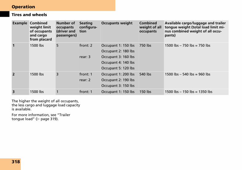
Operation
Tires and wheels
The higher the weight of all occupants, the less cargo and luggage load capacity is available.
For more information, see “Trailer tongue load” (� page 319).
Example Combined weight limit of occupants and cargo from placard
Number of occupants (driver and passengers)
Seating configura-tion
Occupants weight Combined weight of all occupants
Available cargo/luggage and trailer tongue weight (total load limit mi-nus combined weight of all occu-pants)
1 1500 lbs 5 front: 2
rear: 3
Occupant 1: 150 lbs
Occupant 2: 180 lbs
Occupant 3: 160 lbs
Occupant 4: 140 lbs
Occupant 5: 120 lbs
750 lbs 1500 lbs – 750 lbs = 750 lbs
2 1500 lbs 3 front: 1
rear: 2
Occupant 1: 200 lbs
Occupant 2: 190 lbs
Occupant 3: 150 lbs
540 lbs 1500 lbs – 540 lbs = 960 lbs
3 1500 lbs 1 front: 1 Occupant 1: 150 lbs 150 lbs 1500 lbs – 150 lbs = 1350 lbs
318

Operation
Tires and wheels
Certification label
Even after careful determination of the combined weight of all occupants, cargo and the trailer tongue load (if applica-ble) (� page 319) as to not exceed the permissible load limit, you must make sure your vehicle never exceeds the Gross Vehicle Weight Rating (GVWR) and the Gross Axle Weight Rating (GAWR) for ei-ther the front or rear axle. You can ob-tain the GVWR and GAWR from the certification label. The certification label can be found on the driver’s door B-pil-lar, see “Technical data” (� page 432).
Gross Vehicle Weight Rating (GVWR): The total weight of the vehicle, all occu-pants, all cargo, and the trailer tongue load (� page 319) must never exceed the GVWR.
Gross Axle Weight Rating (GAWR): The total allowable weight that can be car-ried by a single axle (front or rear).
To assure that your vehicle does not ex-ceed the maximum permissible weight limits (GVWR and GAWR for front and rear axle), have the loaded vehicle (in-cluding driver, passengers and all cargo and, if applicable, trailer fully loaded) weighed on a suitable commercial scale.
Trailer tongue load
The tongue load of any trailer is an im-portant weight to measure because it af-fects the load you can carry in your vehicle. If a trailer is towed, the tongue load must be added to the weight of all occupants riding and any cargo you are carrying in the vehicle. The tongue load typically is 10 percent of the trailer weight and everything loaded in it.
Your Maybach has been designed prima-rily to carry passengers and their cargo. We not recommend trailer towing with your vehicle.
Your vehicle is equipped with the Tire and Loading Information placard located on the driver’s door B-pillar (� page 315).
The tire inflation pressure should be checked regularly and should only be ad-justed on cold tires. The tires can be con-sidered cold if the vehicle has been parked for at least 3 hours or driven less than 1 mile (1.6 km).
Follow recommended cold tire inflation pressures listed on Tire and Loading In-formation placard on the driver’s door B-pillar.
Keeping the tires properly inflated provides the best handling, tread life and riding comfort.
Recommended tire inflation pressure
Warning! G
Follow recommended tire inflation pressures.
Do not underinflate tires. Underinflated tires wear excessively and/or unevenly, adversely affect handling and fuel econo-my, and are more likely to fail from being overheated.
Do not overinflate tires. Overinflated tires can adversely affect handling and ride comfort, wear unevenly, increase stopping distance, and result in sudden deflation (blowout) because they are more likely to become punctured or damaged by road debris, potholes etc.
319

Operation
Tires and wheels
In addition to the Tire and Loading Infor-mation placard on the driver’s door B-pil-lar, also consult the fuel filler flap for any additional information pertaining to special driving situations. For more infor-mation, see “Important notes on tire in-flation pressure” (� page 320).
i Data shown on placard example are for il-lustration purposes only. Load limit data are specific to each vehicle and may vary from data shown in the illustration below. Refer to placard on vehicle for actual data specific to your vehicle.
1 Tire and Loading Information placard with recommended cold tire inflation pressures
The Tire and Loading Information plac-ard lists the recommended cold tire infla-tion pressures for maximum loaded vehicle weight. The tire inflation pres-sures listed apply to the tires installed as original equipment.
Important notes on tire inflation pressure
Tire temperature and tire inflation pres-sure are also increased while driving, de-pending on the driving speed and the tire load.
If you will be driving your vehicle at high speeds of 100 mph (160 km/h) or higher, where it is legal and conditions allow, consult the placard on the inside of the fuel filler flap on how to adjust the cold tire inflation pressure. If you do not ad-just the tire inflation pressure, excessive heat can build up and result in sudden tire failure.
i Driving comfort may be reduced when the tire inflation pressure is adjusted to the value for speeds above 100 mph (160 km/h) as specified on the placard located on the inside of the fuel filler flap.
Be sure to readjust the tire inflation pressure for normal driving speeds. You should wait until the tires are cold before adjusting the tire inflation pressure.
Some vehicles may have supplemental tire inflation pressure information for vehicle loads less than the maximum loaded vehicle condition. If such infor-mation is provided, it can be found on the placard located on the inside of the fuel filler flap.
Tire inflation pressure changes by ap-proximately 1.5 psi (0.1 bar) per 18°F (10°C) of air temperature change. Keep this in mind when checking tire inflation pressure where the temperature is dif-ferent from the outside temperature.
Warning! G
If the tire inflation pressure repeatedly drops:
� Check the tires for punctures from foreign objects.
� Check to see whether air is leaking from the valves or from around the rim.
320

Operation
Tires and wheels
Regularly check your tire inflation pres-sure at least once a month.
Check and adjust the tire inflation pressure when the tires are cold. The tires can be considered cold if the vehicle has been parked for at least 3 hours or driven less than 1 mile (1.6 km).
If you check the tire inflation pressure when the tires are warm (the vehicle has been driven for several miles or sitting less than 3 hours), the reading will be approximately 4 psi (0.3 bar) higher than the cold reading. This is normal. Do not let air out to match the specified cold tire inflation pressure. Otherwise, the tire will be underinflated.
Checking tire inflation pressure manually
Follow the steps below to achieve correct tire inflation pressure:
� Remove the cap from the valve on one tire.
� Firmly press a tire gauge onto the valve.
� Read tire inflation pressure on tire gauge and check against the recom-mended tire inflation pressure on the placard on the driver’s door B-pillar (� page 315). If necessary, add air to achieve the recommended tire infla-tion pressure.
i If you have overfilled the tire, release tire inflation pressure by pushing the metal stem of the valve with e.g. a tip of a pen. Then re-check the tire inflation pressure with the tire gauge.
� Install the valve cap.
� Repeat this procedure for each tire.
Checking tire inflation pressureWarning! G
Follow recommend tire inflation pressures.
Do not underinflate tires. Underinflated tires wear excessively and/or unevenly, adversely affect handling and fuel econo-my, and are more likely to fail from being overheated.
Do not overinflate tires. Overinflated tires can adversely affect handling and ride comfort, wear unevenly, increase stopping distance, and result in sudden deflation (blowout) because they are more likely to become punctured or damaged by road debris, potholes etc.
Do not overload the tires by exceeding the specified load limit as indicated on the placard on the driver’s door B-pillar (� page 315). Overloading the tires can overheat them, possibly causing a blowout.
321

Operation
Tires and wheels
Checking tire inflation pressure electronically
The tire inflation pressure monitor only functions on wheels that are equipped with the proper electronic sensors. It monitors the tire inflation pressure, as selected by the driver, in all four tires. A warning is issued to alert you to a de-crease in tire inflation pressure in one or more of the tires.
You can call up the tire inflation pressure monitoring display using the control system (� page 157).
i USA only:This device complies with Part 15 of the FCC Rules. Operation is subject to the following two conditions:
(1) This device may not cause harmful inter-ference, and
(2) this device must accept any interference received, including interference that may cause undesired operation.
Any unauthorized modification to this device could void the user’s authority to operate the equipment.
i Canada only:This device complies with RSS-210 of Industry Canada. Operation is subject to the following two conditions:
(1) This device may not cause interference, and
(2) this device must accept any interference received, including interference that may cause undesired operation of the device.
Any unauthorized modification to this device could void the user’s authority to operate the equipment.
i After you have reactivated the tire infla-tion pressure monitor, the current tire infla-tion pressures will only be shown after a few minutes’ driving time.
During this time, you will see the following message in the multifunction display:
TIRE PRES. DISPLAYAPPEARS AFTER DRIVING A FEW MINUTES
i Possible differences between the readings of a tire inflation pressure gauge of an air hose, e.g. gas station equipment, and the ve-hicle’s control system can occur. The readings issued by the control system are more precise.
� Switch on the ignition (� page 60).
� Press button è or ÿ on the mul-tifunction steering wheel repeatedly until the standard display menu appears in the multifunction display (� page 162).
� Press button j or k repeatedly until the current tire inflation pres-sures for each tire appear in the mul-tifunction display.
Warning! G
When the tire inflation pressure monitor-ing system warning light is lit, one or more of your tires is significantly underinflated. You should stop and check your tires as soon as possible, and inflate them to the proper tire inflation pressure as indicated on the vehicle’s tire information placard. Driving on a significantly underinflated tire causes the tire to overheat and can lead to tire failure. Underinflation also re-duces fuel efficiency and tire tread life, and may affect the vehicle’s handling and stopping ability. Each tire, including the spare, should be checked monthly when cold and set to the recommended tire in-flation pressure as specified in the vehicle placard and owner’s manual.
322

Operation
Tires and wheels
i The recommended tire inflation pressures for your vehicle can be found on the tire plac-ard located on the driver’s door B-pillar (� page 315). The tire inflation pressures are not listed in the owner’s manual.
i Operating radio transmission equipment (e.g. wireless headsets, two-way radios) in or near the vehicle could cause the tire inflation pressure monitor to malfunction.
Reactivating the tire inflation pressure monitor
The tire inflation pressure monitor must be reactivated in the following situa-tions:
� if you have changed the tire inflation pressure
� if you have replaced the wheels or tires
� if you have installed new wheels or tires
� Using the tire placard on the driver’s door B-pillar or, if available, the in-side of the fuel filler flap, make sure the tire inflation pressure of all four tires is correct.
� Press button è or ÿ on the mul-tifunction steering wheel repeatedly until the standard display menu appears in the multifunction display (� page 157).
� Press button j or k repeatedly until you see the current tire inflation pressures for each tire appear in the multifunction display or the follow-ing message appears in the multi-function display:
TIRE PRES. DISPLAYAPPEARS AFTER DRIVING A FEW MINUTES
i If you are transporting a deflated tire in the vehicle, do not activate the tire inflation pressure monitor until
� the deflated tire is no longer in the vehicle
� you have inflated the tire to the correct tire inflation pressure
� Press the reset button J in the in-strument cluster (� page 154).
The following message will appear in the multifunction display:
MONITOR CURRENTTIRE PRESSURES?
Warning! G
The tire inflation pressure monitor does not indicate a warning for wrongly select-ed tire inflation pressures. Always adjust tire inflation pressure according to the placard on the driver’s door B-pillar or, if available, the inside of the fuel filler flap.
The tire inflation pressure monitor is not able to issue a warning due to a sudden dramatic loss of tire inflation pressure (e.g. tire blowout caused by a foreign object). In this case bring the vehicle to a halt by care-fully applying the brakes and avoiding abrupt steering maneuvers.
��
323

Operation
Tires and wheels
�
� Press the æ button.The following message will appear in the multifunction display:
TIRE PRES. MONITOR REACTIVATED
The tire inflation pressure monitor will now monitor the tire inflation pressure values of all four tires.
The following message will appear in the multifunction display:
TIRE PRES. DISPLAYAPPEARS AFTER DRIVING A FEW MINUTES
This display appears until the individ-ual tire inflation pressure values are matched with the tires. The individu-al values are then displayed (� page 322).
If you wish to cancel activation:
� Press the ç button.
If one of the following messages appears in the multifunction display:
� TIRE PRES. MONITORREACTIVATE AFTERCORRECTING PRESSURE
� TIRE PRESSURE PLEASE CORRECT
� Check the tire inflation pressures and correct them if necessary.
� Reactivate the tire inflation pressure monitor.
Flat tire
If a tire is deflating the message:
CAUTION-TIRE DEFECT
appears in the multifunction display.
If a tire inflation pressure is low the message:
CHECK TIRE
appears in the multifunction display.
Additional warning messages may also appear in the multifunction display. Read and observe the warning messages in the multifunction display and follow the instructions for each message. See the “Practical hints” section (� page 374) and (� page 396) for a listing of warning messages and instructions.
�Warning! G
Driving with underinflated or damaged tire(s) produces worse than normal and un-expected vehicle operational characteris-tics. Overriding the speed limitation is potentially dangerous as higher speeds and quick acceleration, as produced by your depressing the accelerator pedal fully and briskly, may intensify adverse vehicle handling characteristics.
Warning! G
You should pull over immediately. The ve-hicle no longer has steering stability and may skid. Change the wheel.
Warning! G
Do not drive with a flat tire. A flat tire af-fects the ability to steer or brake the vehi-cle. You may lose control of the vehicle. Continued driving with a flat tire will cause excessive heat build-up and possibly a fire.
324

Operation
Tires and wheels
Potential problems associated with underinflated and overinflated tires
Underinflated tires
Underinflated tires can:
� cause excessive and uneven tire wear
� adversely affect fuel economy
� lead to tire failure from being overheated
� adversely affect handling characteristics
Overinflated tires
Overinflated tires can:
� adversely affect handling characteristics
� cause uneven tire wear
� be more prone to damage from road hazards
� adversely affect ride comfort
� increase stopping distance
Warning! G
Follow recommended tire inflation pressures.
Do not underinflate tires. Underinflated tires wear excessively and/or unevenly, adversely affect handling and fuel econo-my, and are more likely to fail from being overheated.
Warning! G
Follow recommended tire inflation pressures.
Do not overinflate tires. Overinflated tires can adversely affect handling and ride comfort, wear unevenly, increase stopping distance, and result in sudden deflation (blowout) because they are more likely to become punctured or damaged by road debris, potholes etc.
325
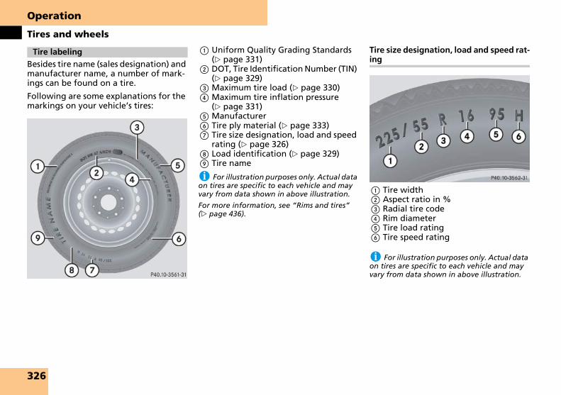
Operation
Tires and wheels
Besides tire name (sales designation) and manufacturer name, a number of mark-ings can be found on a tire.
Following are some explanations for the markings on your vehicle’s tires:
1 Uniform Quality Grading Standards (� page 331)
2 DOT, Tire Identification Number (TIN) (� page 329)
3 Maximum tire load (� page 330)4 Maximum tire inflation pressure
(� page 331)5 Manufacturer6 Tire ply material (� page 333)7 Tire size designation, load and speed
rating (� page 326)8 Load identification (� page 329)9 Tire name
i For illustration purposes only. Actual data on tires are specific to each vehicle and may vary from data shown in above illustration.
For more information, see “Rims and tires” (� page 436).
Tire size designation, load and speed rat-ing
1 Tire width 2 Aspect ratio in %3 Radial tire code4 Rim diameter5 Tire load rating6 Tire speed rating
i For illustration purposes only. Actual data on tires are specific to each vehicle and may vary from data shown in above illustration.
Tire labeling
326

Operation
Tires and wheels
General:
Depending on the design standards used, the tire size molded into the side-wall may have no letter or a letter pre-ceding the tire size designation.
No letter preceding the size designation (as illustrated above): Passenger car tire based on European design standards.
Letter “P” preceding the size designa-tion: Passenger car tire based on U.S. de-sign standards.
Letter “LT” preceding the size designa-tion: Light Truck tire based on U.S. de-sign standards.
Letter “T” preceding the size designa-tion: Temporary spare tires which are high pressure compact spares designed for temporary emergency use only.
Tire width
The tire width 1 (� page 326) indicates the nominal tire width in mm.
Aspect ratio
The aspect ratio 2 (� page 326) is the dimensional relationship between tire section height and section width and is expressed in percentage. The aspect ra-tio is arrived at by dividing section height by section width.
Tire code
The tire code 3 (� page 326) indicates the tire construction type. The “R” stands for radial tire type. Letter “D” means di-agonal or bias ply construction; letter “B” means belted-bias ply construction.
At the tire manufacturer’s option, any tire with a speed capability above 149 mph (240 km/h) can include a “ZR” in the size designation (for example: 245/40 ZR 18). For additional information, see “Tire speed rating” (� page 328).
Rim diameter
The rim diameter 4 (� page 326) is the diameter of the bead seat, not the diameter of the rim edge. Rim diameter is indicated in inches (in).
Tire load rating
The tire load rating 5 (� page 326) is a numerical code associated with the maximum load a tire can support.
For example, a load rating of 91 corre-sponds to a maximum load of 1356 lb (615 kg) the tire is designed to support. See also “Maximum tire load” (� page 330) where the maximum load associated with the load index is indicat-ed in kilograms and lb.
For additional information on tire load rating, see “Load identification” (� page 329).
i Tire load rating 5 (� page 326) and tire speed rating 6 (� page 326) are also referred to as “service description”.
Warning! G
The tire load rating must always be at least half of the GAWR (� page 334) of your ve-hicle. Otherwise, tire failure may be the re-sult which may cause an accident and/or serious injury to you or others.
Always replace rims and tires with the same designation, manufacturer and type as shown on the original part.
Warning! G
Do not overload the tires by exceeding the specified load limit as indicated on the placard located on the driver’s door B-pil-lar (� page 315). Overloading the tires can overheat them, possibly causing a blow-out. Overloading the tires can also result in handling or steering problems, or brake failure.
327
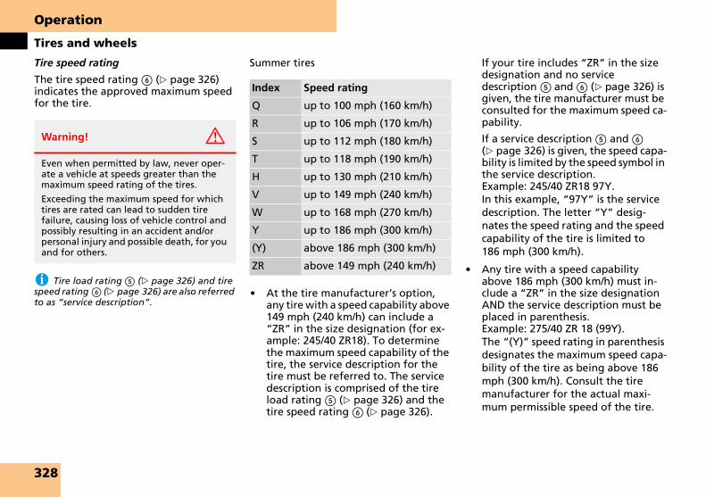
Operation
Tires and wheels
Tire speed rating
The tire speed rating 6 (� page 326) indicates the approved maximum speed for the tire.
i Tire load rating 5 (� page 326) and tire speed rating 6 (� page 326) are also referred to as “service description”.
Summer tires
� At the tire manufacturer’s option, any tire with a speed capability above 149 mph (240 km/h) can include a “ZR” in the size designation (for ex-ample: 245/40 ZR18). To determine the maximum speed capability of the tire, the service description for the tire must be referred to. The service description is comprised of the tire load rating 5 (� page 326) and the tire speed rating 6 (� page 326).
If your tire includes “ZR” in the size designation and no service description 5 and 6 (� page 326) is given, the tire manufacturer must be consulted for the maximum speed ca-pability.
If a service description 5 and 6 (� page 326) is given, the speed capa-bility is limited by the speed symbol in the service description. Example: 245/40 ZR18 97Y. In this example, “97Y” is the service description. The letter “Y” desig-nates the speed rating and the speed capability of the tire is limited to 186 mph (300 km/h).
� Any tire with a speed capability above 186 mph (300 km/h) must in-clude a “ZR” in the size designation AND the service description must be placed in parenthesis. Example: 275/40 ZR 18 (99Y). The “(Y)” speed rating in parenthesis designates the maximum speed capa-bility of the tire as being above 186 mph (300 km/h). Consult the tire manufacturer for the actual maxi-mum permissible speed of the tire.
Warning! G
Even when permitted by law, never oper-ate a vehicle at speeds greater than the maximum speed rating of the tires.
Exceeding the maximum speed for which tires are rated can lead to sudden tire failure, causing loss of vehicle control and possibly resulting in an accident and/or personal injury and possible death, for you and for others.
Index Speed rating
Q up to 100 mph (160 km/h)
R up to 106 mph (170 km/h)
S up to 112 mph (180 km/h)
T up to 118 mph (190 km/h)
H up to 130 mph (210 km/h)
V up to 149 mph (240 km/h)
W up to 168 mph (270 km/h)
Y up to 186 mph (300 km/h)
(Y) above 186 mph (300 km/h)
ZR above 149 mph (240 km/h)
328

Operation
Tires and wheels
All-season and winter tires
i Not all M+S rated tires provide special winter performance. Make sure the tires you use show M+S and the mountain/snow-flake.marking on the tire sidewall. These tires meet specific snow traction performance requirements of the Rubber Manufacturers Association (RMA) and the Rubber Association of Canada (RAC) and have been designed spe-cifically for use in snow conditions.
1 Load identification
i For illustration purposes only. Actual data on tires are specific to each vehicle and may vary from data shown in above illustration.
In addition to tire load rating, special load identification 1 may be molded into the tire sidewall following the letter designating the tire speed rating 6 (� page 326).
No specification given: absence of any text (like in above example) indicates a standard load (SL) tire.
XL (Extra Load): designates an extra load (or reinforced) tire.
Light Load: designates a light load tire.
C, D, E: designates load range associated with the maximum load a tire can carry at a specified pressure.
U.S. tire regulations require each new tire manufacturer or tire retreader to mold a TIN into or onto a sidewall of each tire produced.
The TIN is a unique identifier which facil-itates efforts by tire manufactures to no-tify purchasers in recall situations or other safety matters concerning tires and gives purchasers the means to easily identify such tires.
The TIN is comprised of “Manufacturer’s identification mark”, “Tire size”, “Tire type code” and “Date of manufacture”.
Index Speed rating
Q M+S1
1 or M+S.for winter tires
up to 100 mph (160 km/h)
T M+S1 up to 118 mph (190 km/h)
H M+S1 up to 130 mph (210 km/h)
V M+S1 up to 149 mph (240 km/h)
Load identification
DOT, Tire Identification Number (TIN)
329

Operation
Tires and wheels
1 DOT 2 Manufacturer’s identification mark3 Tire size4 Tire type code (at the option of the
tire manufacturer)5 Date of manufacture
i For illustration purposes only. Actual data on tires are specific to each vehicle and may vary from data shown in above illustration.
DOT (Department of Transportation)
A tire branding symbol 1 which denotes the tire meets requirements of the U.S. Department of Transportation.
Manufacturer’s identification mark
The manufacturer’s identification mark 2 denotes the tire manufacturer.
New tires have a mark with two symbols.
Retreaded tires have a mark with four symbols. For more information on re-treaded tires (� page 313).
Tire size
The code 3 indicates the tire size.
Tire type code
The code 4 may, at the option of the manufacturer, be used as a descriptive code for identifying significant charac-teristics of the tire.
Date of manufacture
The date of manufacture 5 identifies the week and year of manufacture.
The first two figures identify the week, starting with “01” to represent the first full week of the calendar year. The sec-ond two figures represent the year.
For example, “3106” represents the 31st week of 2006.
1 Maximum tire load rating
i For illustration purposes only. Actual data on tires are specific to each vehicle and may vary from data shown in above illustration.
The maximum tire load is the maximum weight the tires are designed to support.
Maximum tire load
Warning! G
Do not overload the tires by exceeding the specified load limit as indicated on the placard located on the driver’s door B-pil-lar (� page 315). Overloading the tires can overheat them, possibly causing a blow-out. Overloading the tires can also result in handling or steering problems, or brake failure.
330

Operation
Tires and wheels
For more information on tire load rating (� page 328).
For information on calculating total and cargo load capacities (� page 316).
1 Maximum permissible tire inflation pressure
i For illustration purposes only. Actual data on tires are specific to each vehicle and may vary from data shown in above illustration.
This is the maximum permissible tire inflation pressure for the tire.
Always follow the recommended tire inflation pressure (� page 319) for prop-er tire inflation.
Tire manufacturers are required to grade tires based on three performance factors: treadwear, traction and temperature resistance.
1 Treadwear2 Traction3 Temperature resistance
i For illustration purposes only. Actual data on tires are specific to each vehicle and may vary from data shown in above illustration.
Maximum tire inflation pressure
Warning! G
Never exceed the max. tire inflation pressure. Follow recommended tire infla-tion pressures.
Do not underinflate tires. Underinflated tires wear excessively and/or unevenly, ad-versely affect handling and fuel economy, and are more likely to fail from being over-heated.
Do not overinflate tires. Overinflated tires can adversely affect handling and ride comfort, wear unevenly, increase stopping distance, and result in sudden deflation (blowout) because they are more likely to become punctured or damaged by road debris, potholes etc.
Uniform Tire Quality Grading Stan-dards (U.S. vehicles)
331

Operation
Tires and wheels
Quality grades can be found, where ap-plicable, on the tire sidewall between tread shoulder and maximum section width. For example:
All passenger car tires must conform to federal safety requirements in addition to these grades.
Treadwear
The treadwear grade is a comparative rating based on the wear rate of the tire when tested under controlled conditions on a specified government test course. For example, a tire graded 150 would wear one and one-half (1 1/2) times as well on the government course as a tire graded 100. The relative performance of tires depends upon the actual conditions of their use, however, and may depart significantly from the norm due to varia-tions in driving habits, service practices and differences in road characteristics and climate.
Traction
The traction grades, from highest to low-est, are AA, A, B, and C. Those grades represent the tire’s ability to stop on wet pavement as measured under controlled conditions on specified government test surfaces of asphalt and concrete. A tire marked C may have poor traction perfor-mance.
Temperature
The temperature grades are A (the high-est), B, and C, representing the tire’s re-sistance to the generation of heat and its ability to dissipate heat when tested un-der controlled conditions on a specified indoor laboratory test wheel. Sustained high temperature can cause the material of the tire to degenerate and reduce tire life, and excessive temperature can lead to sudden tire failure. The grade C corre-sponds to a level of performance which all passenger car tires must meet under the Federal Motor Vehicle Safety Stan-dard No. 109. Grades B and A represent higher levels of performance on the lab-oratory test wheel than the minimum re-quired by law.
Treadwear Traction Temperature
200 AA A
Warning! G
The traction grade assigned to this tire is based on straight-ahead braking traction tests, and does not include acceleration, cornering, hydroplaning, or peak traction characteristics.
Warning! G
The temperature grade for this tire is es-tablished for a tire that is properly inflated and not overloaded. Excessive speed, un-derinflation, or excessive loading, either separately or in combination, can cause ex-cessive heat build-up and possible tire fail-ure.
332

Operation
Tires and wheels
1 Plies in sidewall2 Plies under tread
i For illustration purposes only. Actual data on tires are specific to each vehicle and may vary from data shown in above illustration.
This marking tells you about the type of cord and number of plies in the sidewall and under the tread.
Accessory weight
The combined weight (in excess of those standard items which may be replaced) of automatic transmission, power steer-ing, power brakes, power windows, power seats, radio, and heater, to the ex-tent that these items are available as fac-tory-installed equipment (whether installed or not).
Air pressure
The amount of air inside the tire pressing outward on each square inch of the tire. Air pressure is expressed in pounds per square inch (psi), or kilopascal (kPa) or bars.
Aspect ratio
Dimensional relationship between tire section height and section width expressed in percentage.
Bar
Another metric unit for air pressure. There are 14.5038 pounds per square inch (psi) to 1 bar; there are 100 kilopascals (kPa) to 1 bar.
Bead
The tire bead contains steel wires wrapped by steel cords that hold the tire onto the rim.
Cold tire inflation pressure
Tire inflation pressure when your vehicle has been sitting for at least 3 hours or driven no more than 1 mi (1.6 km).
Curb weight
The weight of a motor vehicle with stan-dard equipment including the maximum capacity of fuel, oil, and coolant, and, if so equipped, air conditioning and addi-tional optional equipment, but without passengers and cargo.
DOT (Department of Transportation)
A tire branding symbol which denotes the tire meets requirements of the U.S. Department of Transportation.
Tire ply material Tire and loading terminology
333

Operation
Tires and wheels
GAWR (Gross Axle Weight Rating)
The GAWR is the maximum permissible axle weight. The gross vehicle weight on each axle must never exceed the GAWR for the front and rear axle indicated on the certification label located on the driver’s door B-pillar.
GVW (Gross Vehicle Weight)
The GVW comprises the weight of the vehicle including fuel, tools, spare wheel, installed accessories, passengers and cargo and, if applicable, trailer tongue load. The GVW must never exceed the GVWR indicated on the certification la-bel located on the driver’s door B-pillar.
GVWR (Gross Vehicle Weight Rating)
This is the maximum permissible vehicle weight of the fully loaded vehicle (weight of the vehicle including all op-tions, passengers, fuel, and cargo and, if applicable, trailer tongue load). It is indi-cated on certification label located on the driver’s door B-pillar.
Kilopascal (kPa)
The metric unit for air pressure. There are 6.9 kilopascals (kPa) to 1 psi; another metric unit for air pressure is bars. There are 100 kilopascals (kPa) to 1 bar.
Maximum load rating
The maximum load in kilograms and pounds that can be carried by the tire.
Maximum loaded vehicle weight
The sum of curb weight, accessory weight, total load limit, and production options weight.
Maximum tire inflation pressure
This number is the greatest amount of air pressure that should ever be put in the tire under normal driving conditions.
Normal occupant weight
The number of occupants the vehicle is designed to seat, multiplied by 68 kilograms (150 lb).
Occupant distribution
The distribution of occupants in a vehicle at their designated seating positions.
Production options weight
The combined weight of those installed regular production options weighing over 5 lb (2.3 kilograms) in excess of those standard items which they replace, not previously considered in curb weight or accessory weight, including heavy duty brakes, ride levelers, roof rack, heavy duty battery, and special trim.
PSI (Pounds per square inch)
A standard unit of measure for air pres-sure -> bar, kilopascal (kPa).
Recommended tire inflation pressure
Recommended tire inflation pressure listed on Tire and Loading Information placard located on driver’s door B-pillar for normal driving conditions. Provides best handling, tread life and riding com-fort.
Rim
A metal support for a tire or a tire and tube assembly upon which the tire beads are seated.
Sidewall
The portion of a tire between the tread and the bead.
334

Operation
Tires and wheels
TIN (Tire Identification Number)
Unique identifier which facilitates ef-forts by tire manufacturers to notify pur-chasers in recall situations or other safety matters concerning tires and gives pur-chases the means to easily identify such tires. The TIN is comprised of “Manufac-turer’s identification mark”, “Tire size”, “Tire type code” and “Date of manufac-ture”.
Tire load rating
Numerical code associated with the maximum load a tire can support.
Tire ply composition and material used
This indicates the number of plies or the number of layers of rubber-coated fabric in the tire tread and sidewall. Tire manu-facturers also must indicate the ply mate-rials in the tire and sidewall, which include steel, nylon, polyester, and oth-ers.
Tire speed rating
Part of tire designation; indicates the speed range for which a tire is approved.
Total load limit
Rated cargo and luggage load plus 68 kilograms (150 lb) times the vehicle’s designated seating capacity.
Traction
Force exerted by the vehicle on the road via the tires. The amount of grip provid-ed.
Tread
The portion of a tire that comes into contact with the road.
Treadwear indicators
Narrow bands, sometimes called “wear bars” that show across the tread of a tire when only 1/16 in (1.6 mm) of tread remains.
Uniform Tire Quality Grading Standards
A tire information system that provides consumers with ratings for a tire’s trac-tion, temperature and treadwear. Rat-ings are determined by tire manufacturers using government testing procedures. The ratings are molded into the sidewall of the tire.
Vehicle maximum load on the tire
Load on an individual tire that is determined by distributing to each axle its share of the maximum loaded vehicle weight and dividing it by two.
335

Operation
Tires and wheels
Tire rotation can be performed on vehi-cles with tires of the same dimension all around. If your vehicle is equipped with tires of the same dimension all around, tires can be rotated, observing a front-to-rear rotation pattern that will main-tain the intended rotation (spinning) di-rection of the tire (� page 315).
In some cases, such as when your vehicle is equipped with mixed-size tires (differ-ent tire dimension front vs. rear), tire ro-tation is not possible.
If applicable to your vehicle’s tire config-uration, tires can be rotated according to the tire manufacturer’s recommended intervals in the tire manufacturer’s warranty pamphlet located in your vehicle literature portfolio. If none is available, tires should be rotated every 3000 to 6000 miles (5000 to 10000 km), or sooner if necessary, according to the degree of tire wear. The same rotation (spinning) direction must be maintained (� page 315).
Rotate tires before the characteristic tire wear pattern becomes visible (shoulder wear on front tires and tread center wear on rear tires).
Thoroughly clean the mounting face of wheels and brake disks, i.e. the inner side of the wheels/tires, during each rotation. Check for and ensure proper tire infla-tion pressure, activating the tire inflation pressure monitor if necessary.
! Your vehicle is equipped with a tire infla-tion pressure monitor. Electronic components are built into the wheel.
Do not use mounting tools in the area of the valve as they could damage the electronic components.
To prevent damage or incorrect installation, have the tires changed at an authorized Maybach Studio.
For information on wheel change, see the “Practical hints” section (� page 400) and (� page 413).
Rotating tires
Warning! G
Rotate front and rear wheels only if the tires are of the same dimension.
If your vehicle is equipped with mixed-size tires (different tire dimensions front vs. rear), tire rotation is not possible.
Warning! G
Have the tightening torque checked after changing a wheel. Wheels could become loose if not tightened with a torque of 110 lb-ft (150 Nm).
Only use Genuine Maybach wheel bolts specified for your vehicle’s rims.
336

Operation
Winter driving
Before the onset of winter, have your ve-hicle winterized at an authorized Maybach Studio. This service includes:
� Check of anticorrosion and antifreeze concentration.
� Addition of cleaning concentrate to the water of the windshield and headlamp cleaning system. Add MB Windshield Washer Concentrate “MB SummerFit” to a pre-mixed windshield washer solvent/antifreeze which is formulated for temperatures below freezing point (� page 445).
� Battery test. Battery capacity drops with decreasing ambient tempera-ture. A well-charged battery helps to make sure the engine can be started even at low ambient temperatures.
� Tire change.
If you install winter tires, have an autho-rized Maybach Studio limit the speed of your vehicle to the speed rating of the winter tires installed.
When the speed limitation is activated, the segments up to the set speed limita-tion are illuminated, for example, 130 mph (210 km/h) as in the illustration below.
Vehicle speed limitation for winter tires in speedometer
Always observe the speed rating of the winter tires installed on your vehicle. If the maximum speed for which your tires are rated is below the speed rating of your vehicle, you must place a notice to this effect where it will be seen by the driver. Such notices are available from your tire dealer or from any authorized Maybach Studio.
Winter driving Tire speed rating for winter tires
Warning! G
Even when permitted by law, never oper-ate a vehicle at speeds greater than the maximum speed rating of the tires.
Exceeding the maximum speed for which tires are rated can lead to sudden tire fail-ure, causing loss of vehicle control and pos-sibly resulting in an accident and/or personal injury and possible death, for you and for others.
337

Operation
Winter driving
Always use winter tires at temperatures below 45°F (7°C) and whenever wintry road conditions prevail. Not all M+S rat-ed tires provide special winter perfor-mance. Make sure the tires you use show the mountain/snowflake.marking on the tire sidewall. These tires meet specific snow traction performance require-ments of the Rubber Manufacturers As-sociation (RMA) and the Rubber Association of Canada (RAC) and have been designed specifically for use in snow conditions. Use of winter tires is the only way to achieve the maximum ef-fectiveness of the ABS and the ESP® in winter operation.
For safe handling, make sure all mount-ed winter tires are of the same make and have the same tread design.
! When driving with snow chains, always select the raised level of the vehicle level con-trol system (� page 234). Other settings may result in damage to your vehicle.
Snow chains should only be driven on snow-covered roads at speeds not to ex-ceed 30 mph (50 km/h). Remove chains as soon as possible when driving on roads without snow.
Please observe the following guidelines when using snow chains:
� Using snow chains is not permissible with all wheel/tire combinations (� page 436).
� Use snow chains in pairs and on rear wheels only. Follow the manufactur-er’s mounting instructions.
! If snow chains are mounted to the front wheels, they may scrape against the body or axle components. The tires or the vehicle could be damaged as a result.
� Use only snow chains that are approved by us for use on Maybach vehicles. Any authorized Maybach Studio will be glad to advise you on this subject.
� Use of snow chains may be prohibited depending on location. Always check local and state laws before installing snow chains.
i When driving with snow chains, you may wish to deactivate the ESP® (� page 106) be-fore setting the vehicle in motion. This will im-prove the vehicle‘s traction.
Winter tires
Warning! G
Winter tires with a tread depth of less than 0.16 in (4 mm) must be replaced. They are no longer suitable for winter operation.
Warning! G
If you use your spare tire when winter tires are fitted on the other wheels, be aware that the difference in tire characteristics may very well impair turning stability and that overall driving stability may be re-duced. Adapt your driving style according-ly.
Have the spare tire replaced with a winter tire at the nearest authorized Maybach Studio.
Snow chains
338

Operation
Maintenance
We strongly recommend that you have your vehicle serviced by an authorized Maybach Studio, in accordance with the Maintenance Booklet at the times called for by the maintenance service indicator display.
Failure to have the vehicle maintained in accordance with the Maintenance Book-let and maintenance service indicator at the designated times /mileage will result in vehicle damage not covered by the Maybach Limited Warranty.
The maintenance service indicator mes-sage will notify you when the next main-tenance service is due.
Starting approximately 1 month before the next maintenance service is due, one of the following messages will appear in the multifunction display while you are driving or when you switch on the igni-tion (example service A):
'A' SERVICE IN XXXXX MI
(Canada: IN XXXXX KM)
'A' SERVICE IN XXX DAYS
'A' SERVICE IN X DAY
'A' SERVICE DUE NOW
The type of maintenance service due is indicated in the multifunction display:
9 Basic service (A)
´ Extended service (B)
i Vehicles equipped with Maintenance Sys-tem (U.S. vehicles. Canada vehicles, depend-ing on vehicle production date):
The Maintenance System in your vehicle tracks distance driven and the time elapsed since the last maintenance service and calculates other maintenance service work required.
i Vehicles equipped with FSS (Flexible Ser-vice System) only (Canada vehicles, depending on vehicle production date):
� FSS evaluates engine temperature, oil lev-el, vehicle speed, engine speed, distance driven and the time elapsed since the last service and calculates other maintenance service work required.
� The interval between maintenance servic-es depends on your driving habits. A gentle driving style, moderate engine speeds and the avoidance of short-dis-tance trips will lengthen the interval be-tween services.
Maintenance
Maintenance service indicator mes-sage
339

Operation
Maintenance
Clearing the maintenance service indica-tor message
The maintenance service indicator mes-sage is automatically cleared after ap-proximately 30 seconds when you switch on the ignition or when reaching the maintenance service threshold while driving.
You can also clear it yourself.
1 Reset button J
� Press reset button J 1 on the instru-ment cluster.
The maintenance service indicator message is cleared and the standard display appears in the multifunction display (� page 157).
Maintenance service term exceeded
If you have exceeded the suggested maintenance service term, you will see the following message in the multifunc-tion display example service A):
'A' SERVICE EXCEEDED BYXXXX MI
(Canada: XXXXX KM)
'A' SERVICE EXCEEDED BYXXX DAYS
'A' SERVICE EXCEEDED BYX DAY
In addition, a signal sounds when the message appears.
Any authorized Maybach Studio will re-set the maintenance service indicator fol-lowing a completed maintenance service.
You can call up the maintenance service indicator display at any time to check when the next maintenance service is due.
� Switch on the ignition (� page 60).
� Press button è or ÿ on the mul-tifunction steering wheel repeatedly until the standard display appears in the multifunction display (� page 157).
� Press button k or j until the maintenance service indicator display with the service symbol 9 or ´ and the service deadline appear in the multifunction display.
i If the battery is disconnected, the days of disconnection will not be included in the count shown by the maintenance service indi-cator. To arrive at the true maintenance ser-vice deadline, you will need to subtract these days from the days shown in the maintenance service indicator display.
Do not confuse the maintenance service indi-cator with the engine oil level indicator :.
Calling up the maintenance service in-dicator display
340

Operation
Maintenance
In the event that the maintenance ser-vice on your vehicle is not carried out by an authorized Maybach Studio, you can have the maintenance service indicator reset. The automotive maintenance facil-ity carrying out the maintenance service will find the information for resetting the maintenance service indicator in the maintenance-relevant information for your vehicle. Such information is avail-able from either your authorized Maybach Studio or directly from Mercedes-Benz USA, LLC.
i If the maintenance service indicator was inadvertently reset, have an authorized Maybach Studio correct it.
Only reset if the proper maintenance service has been performed. Resetting the system without performing the proper service as called for by the maintenance service indica-tor will result in engine damage and/or other vehicle damage not covered by the Maybach Limited Warranty.
Resetting the maintenance service in-dicator
341

Operation
Vehicle care
Regular and proper care will help to maintain the value of your vehicle. The best way to protect your vehicle from harmful environmental influences is to wash it and use protective treatments regularly.
i Your authorized Maybach Studio offers a high-end care product case* to ensure that your Maybach receives optimal care at all times and at any location.
While in operation, even while parked, your vehicle is subjected to varying exter-nal influences which, if gone unchecked, can attack the paintwork as well as the vehicle underbody and cause lasting damage.
Such damage is caused not only by ex-treme and varying climatic conditions, but also by:
� Air pollution
� Road salt
� Tar
� Gravel and stone chipping
To avoid paint damage, you should im-mediately remove:
� Grease and oil
� Fuel
� Coolant
� Brake fluid
� Bird droppings
� Insects
� Tree resins, etc.
Frequent washing reduces and/or elimi-nates the aggressiveness and potency of the above adverse influences.
More frequent washings are necessary to deal with unfavorable conditions:
� near the ocean
� in industrial areas (smoke, exhaust emissions)
� during winter operation
You should check your vehicle from time to time for stone chipping or other dam-age. Any damage should be repaired as soon as possible to prevent corrosion.
In doing so, do not neglect the under-body of the vehicle. A prerequisite for a thorough check is a washing of the un-derbody followed by a thorough inspec-tion. Damaged areas need to be re-undercoated.
Your vehicle has been treated at the fac-tory with a wax-base rustproofing in the body cavities which will last for the life-time of the vehicle. Post-production treatment is neither necessary nor rec-ommended by us for use on Maybach ve-hicles because of the possibility of incompatibility between materials used in the production process and others ap-plied later.
Vehicle care
Cleaning and care of vehicle
Warning! G
Many cleaning products can be hazardous. Some are poisonous, others are flamma-ble. Always follow the instructions on the particular container. Always open your ve-hicle’s doors or windows when cleaning the inside.
Never use fluids or solvents that are not designed for cleaning your vehicle.
Always lock away cleaning products and keep them out of reach of children.
342

Operation
Vehicle care
We have selected car-care products and compiled recommendations which are specially matched to our vehicles and which always reflect the latest technolo-gy. You can obtain car-care products ap-proved by us for use on Maybach vehicles at an authorized Maybach Studio.
Scratches, corrosive deposits, corrosion or damage due to negligent or incorrect care cannot always be removed or re-paired with the car-care products recom-mended here. In such cases it is best to seek aid at an authorized Maybach Studio.
The following topics deal with the clean-ing and care of your vehicle and give im-portant “how-to” information as well as references to car-care products approved by us for use on Maybach vehicles.
Refrigerator**
Clean out the refrigerator regularly with a vinegar-and-water solution. Mix the solution in a ratio of 1 part vinegar to 10 parts water. Allow the refrigerator to dry before using it again.
Power washer
! Follow the instructions provided by the power washer manufacturer on maintaining a distance between the vehicle and the nozzle of the power washer.
Never use a round nozzle to power-wash tires. The intense jet of water can result in damage to the tire.
Always replace a damaged tire.
Always keep the jet of water moving across the surface. Do not aim directly at electrical parts, electrical connectors, seals, or other rubber parts.
i Vehicles with KEYLESS-GO**:If an outside door handle is hit by a strong jet of water, and a SmartKey with KEYLESS-GO** is in close proximity, i.e. within approximately 3 ft (approximately 1 m), the vehicle could be inadvertently locked or unlocked.
Tar stains
Quickly remove tar stains before they dry and become more difficult to remove. A tar remover is recommended.
Paintwork, painted body components
! Affixing stickers, magnets, adhesive tape or similar materials to painted body compo-nents may damage the paintwork.
Paint Care approved by us for use on Maybach vehicles should be applied when water drops on the paint surface do not “bead up”. This should normally be done every 3 to 5 months, depending on climate and washing detergent used.
Paint Cleaner approved by us for use on Maybach vehicles should be applied if the paint surface shows signs of embed-ded dirt (i.e. loss of gloss).
Do not apply any of these products or wax if your vehicle is parked in the sun or if the hood is still hot.
� Use the appropriate Touch-Up Stick approved by us for use on Maybach vehicles for quick and provisional re-pairs of minor paint damage (i.e. chips from stones, vehicle doors, etc.).
343

Operation
Vehicle care
Engine cleaning
Prior to cleaning the engine compart-ment make sure to protect electrical components and connectors from con-tact with water and cleaning agents.
Corrosion protection, such as Anticorro-sion Wax approved by us for use on Maybach vehicles, should be applied to the engine compartment after every en-gine cleaning. Before applying, all con-trol linkage bushings and joints should be lubricated. The poly-V-belt and all pulleys should be protected from any wax.
Vehicle washing
In the winter, thoroughly remove all traces of road salt as soon as possible.
When washing the vehicle underbody, do not forget to clean the inner sides of the wheels.
i Vehicles with KEYLESS-GO**:If an outside door handle is hit by a strong jet of water, and a SmartKey with KEYLESS-GO** is in close proximity, i.e. within approximately 3 ft (approximately 1 m), the vehicle could be inadvertently locked or unlocked.
Hand-wash
Do not use hot water or wash your vehi-cle in direct sunlight.
� Only use a mild car wash detergent, such as Car Shampoo approved by us for use on Maybach vehicles.
� Thoroughly spray the vehicle with a diffused jet of water.
Direct only a very weak spray towards the ventilation intake.
� Use plenty of water and rinse the sponge and chamois frequently.
� Rinse with clean water and thorough-ly dry with a chamois.
Do not allow cleaning agents to dry on the finish.
! Do not use scouring agents on these parts.
Never apply strong force and only use a soft, non-scratching cloth when cleaning the vehi-cle. Do not attempt to wipe the surface with a dry cloth or sponge.
Otherwise you may scratch or damage the paint.
Automatic car wash
You can have your car washed in an au-tomatic car wash from the start. Auto-matic car washes without brushes are preferable.
! Do not clean your vehicle in an automatic touchless car wash which uses caustic spray. Otherwise the caustic spray will damage the paint or ornamental moldings.
If the vehicle is very dirty, prewash it be-fore running it through the automatic car wash.
! Make sure the windshield wiper switch is set to 0 (� page 74). Otherwise, e.g. the rain sensor could activate and cause the wipers to move unintentionally. This may lead to vehicle damage.
Due to the width of the vehicle, fold in exteri-or rear view mirrors prior to running the vehi-cle through an automatic car wash to prevent damage to the mirrors.
344

Operation
Vehicle care
i After running the vehicle through an au-tomatic car wash, wipe any wax off of the windshield (� page 347). This will prevent smears and reduce wiping noise which can be caused by residual wax on the windshield.
When leaving the car wash, make sure the mirrors are folded out. Otherwise they may vi-brate.
Ornamental moldings
For regular cleaning and care of orna-mental moldings, use a damp cloth.
! Do not use chrome cleaner on ornamental moldings. Although ornamental moldings may have chrome appearance, they could be made of anodized aluminum that will be damaged when cleaned with chrome cleaner. Instead, use a damp cloth to clean those orna-mental moldings.
For very dirty ornamental moldings of which you are sure are chrome-plated, use a chrome cleaner. If in doubt whether an ornamental molding is chrome-plated, contact an autho-rized Maybach Studio.
Headlamps, tail lamps, side markers, turn signal lenses
� Use a mild car wash detergent, such as Car Shampoo approved by us for use on Maybach vehicles, with plenty of water.
! Only use window cleaning solutions that are suitable for plastic lamp lenses. Window cleaning solutions which are not suitable may damage the plastic lamp lenses of the head-lamps. Therefore, do not use abrasives, sol-vents or cleaners that contain solvents.
Never apply strong force and only use a soft, non-scratching cloth when cleaning the lens-es. Do not attempt to wipe dirty lenses with a dry cloth or sponge.
Otherwise you may scratch or damage the lens surface.
345

Operation
Vehicle care
Cleaning the Distronic** system sensor cover
1 Distronic system sensor cover
� Switch off the ignition (� page 60).
� Use a mild car wash detergent, such as Car Shampoo approved by us for use on Maybach vehicles, with plenty of water and a non-scratching cloth to clean sensor cover 1.
! To prevent scratches or damage, never apply strong force and only use a soft, non-scratching cloth when cleaning the sensor cover 1. Do not attempt to wipe dirty sensors with a dry cloth or sponge.
� Restart the engine after cleaning sen-sor cover 1.
Cleaning the Parktronic system sensors
1 Parktronic system sensors in front bumper
� Use a mild car wash detergent, such as Car Shampoo approved by us for use on Maybach vehicles, with plenty of water and a soft, non-scratching cloth to clean sensors 1 on the bumpers.
! Do not apply strong pressure to the sen-sor covers. Applying strong pressure may dam-age the sensor covers.
Follow the instructions provided by the power washer manufacturer on maintaining a dis-tance between the vehicle and the nozzle of the power washer.
! To prevent scratches, never apply strong force and only use a soft, non-scratching cloth when cleaning the sensors. Do not attempt to wipe dirty sensors with a dry cloth or sponge.
346
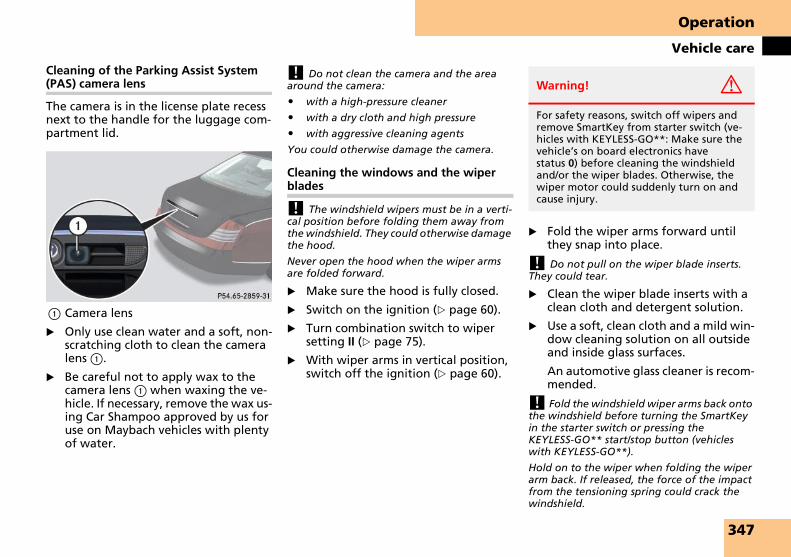
Operation
Vehicle care
Cleaning of the Parking Assist System (PAS) camera lens
The camera is in the license plate recess next to the handle for the luggage com-partment lid.
1 Camera lens
� Only use clean water and a soft, non-scratching cloth to clean the camera lens 1.
� Be careful not to apply wax to the camera lens 1 when waxing the ve-hicle. If necessary, remove the wax us-ing Car Shampoo approved by us for use on Maybach vehicles with plenty of water.
! Do not clean the camera and the area around the camera:
� with a high-pressure cleaner
� with a dry cloth and high pressure
� with aggressive cleaning agents
You could otherwise damage the camera.
Cleaning the windows and the wiper blades
! The windshield wipers must be in a verti-cal position before folding them away from the windshield. They could otherwise damage the hood.
Never open the hood when the wiper arms are folded forward.
� Make sure the hood is fully closed.
� Switch on the ignition (� page 60).
� Turn combination switch to wiper setting II (� page 75).
� With wiper arms in vertical position, switch off the ignition (� page 60).
� Fold the wiper arms forward until they snap into place.
! Do not pull on the wiper blade inserts. They could tear.
� Clean the wiper blade inserts with a clean cloth and detergent solution.
� Use a soft, clean cloth and a mild win-dow cleaning solution on all outside and inside glass surfaces.
An automotive glass cleaner is recom-mended.
! Fold the windshield wiper arms back onto the windshield before turning the SmartKey in the starter switch or pressing the KEYLESS-GO** start/stop button (vehicles with KEYLESS-GO**).
Hold on to the wiper when folding the wiper arm back. If released, the force of the impact from the tensioning spring could crack the windshield.
Warning! G
For safety reasons, switch off wipers and remove SmartKey from starter switch (ve-hicles with KEYLESS-GO**: Make sure the vehicle’s on board electronics have status 0) before cleaning the windshield and/or the wiper blades. Otherwise, the wiper motor could suddenly turn on and cause injury.
347

Operation
Vehicle care
! To clean the window interior, do not use a dry cloth, abrasives, solvents or cleaners con-taining solvents. Do not touch the inside of the front, rear or side windows with hard ob-jects such as an ice scraper or ring. Doing so may damage the windows.
Light alloy wheels
If possible, clean wheels once a week.
� Use Wheel Care approved by us for use on Maybach vehicles, a soft bris-tle brush and a strong spray of water for cleaning the light alloy wheels.
! Only use acid-free cleaning materials. Acid may cause corrosion or damage the clear coat.
! The vehicle should not be parked for an extended period of time immediately after it has been cleaned, especially not after the wheel rims have been cleaned with wheel rim cleaner. Wheel rim cleaners can lead to in-creased corrosion of the brake disks and brake pads. Non-approved wheel cleaners may also damage the wheel paint if the car is not driv-en after cleaning. Therefore, the vehicle’s brake system should always be warmed-up before it is parked after cleaning. To do so, please drive your vehicle for several minutes to allow the brakes to dry.
When applying Tire Care and Wheel Care products approved by us for use on Maybach vehicles, take care not to spray them on the brake disks.
Plastic and rubber parts
� Use a gentle dishwashing detergent or mild detergent for delicate fabrics as a washing solution.
� Wipe with a cloth moistened in a lukewarm solution.
The surface may temporarily change color. If this is the case, wait for it to dry.
! Do not use oil, wax or scouring agents on these parts.
Never apply strong force and only use a soft, non-scratching cloth when cleaning the sur-face. Do not attempt to wipe the surface with a dry cloth or sponge.
Otherwise you may scratch or damage the sur-face.
Hard plastic trim items
� Use Interior Care approved by us for use on Maybach vehicles onto a soft lint-free cloth and apply with light pressure.
! Never apply strong force and only use a soft, non-scratching cloth when cleaning the surface. Do not attempt to wipe the surface with a dry cloth or sponge.
Otherwise you may scratch or damage the sur-face.
Instrument cluster and front cup holders
� Use a gentle dishwashing detergent or mild detergent for delicate fabrics as a washing solution.
� Wipe with a cloth moistened in a lukewarm solution.
! To prevent scratches, do not use scouring agents.
Steering wheel and gear selector lever
� Wipe with a damp cloth and dry thor-oughly or clean with Leather Care ap-proved by us for use on Maybach vehicles.
Warning! G
Do not use cleaners or cockpit care sprays containing solvents to clean the cockpit or the steering wheel. Cleaners containing solvents will make the surface porous and vehicle occupants could suffer serious inju-ries from plastic parts coming loose in the event of air bag deployment.
348

Operation
Vehicle care
Carpets
� Use Carpet and Fabric Care approved by us for use on Maybach vehicles for cleaning the carpets.
Rear cup holder/bottle holder
For cleaning purposes, you can push back the cover plate of the cup holder.
Example illustration from Maybach 57
1 Release catch for cup/bottle holder2 Release catch for cup holder3 Release catch for cover plate4 Cover plate
� Press button 2.
The cup holder opens.
� Push one of the release catches 3 upward and, at the same time, press release catch 1 for the cup/bottle holder.
� Push the cover plate 4 back.
� Use a gentle dishwashing detergent or mild detergent for delicate fabrics as a washing solution.
� Wipe with a cloth moistened in a lukewarm solution.
! To prevent scratches, do not use scouring agents.
� After cleaning, close the cup/bottle holder.
The next time the holder is opened, the cover plate slides out with it.
Headliner and shelf below rear window
� Use a soft bristle brush or a dry-sham-poo cleaner in case of excessive dirt.
Roof lining
� Use a soft bristle brush or a dry-sham-poo cleaner in case of excessive dirt.
Seat belts
� Only use clear, lukewarm water and soap.
! The seat belts must not be treated with chemical cleaning agents. Do not dry the seat belts at temperatures above 176°F (80°C) or in direct sunlight.
Upholstery
Using aftermarket seat covers or wearing clothing that have the tendency to give off coloring (e.g. when wet, etc.) may cause the upholstery to become perma-nently discolored. By lining the seats with a proper intermediate cover, con-tact-discoloration will be prevented.
Warning! G
Do not bleach or dye seat belts as this may severely weaken them. In a crash they may not be able to provide adequate protec-tion.
349

Operation
Vehicle care
Leather upholstery
Please note that leather upholstery is a natural product and is therefore subject to a natural aging process. Leather up-holstery may also react to certain ambi-ent influences such as high humidity or high temperature by showing wrinkles for example.
� Wipe leather upholstery with a damp cloth and dry thoroughly or clean with Leather Care approved by us for use on Maybach vehicles.
! Wipe with light pressure to avoid damage to the upholstery.
Exercise particular care when cleaning perforated leather as its underside should not become wet.
Nubuck leather
The nubuck leather upholstery is treated with a protective coating.
� Wipe nubuck leather upholstery with damp microfiber cloth to remove dust and other light stains.
� Carefully dab nubuck leather uphol-stery with a dry microfiber cloth to re-move oil stains.
! Do not use Leather Care approved by us for use on Maybach vehicles on nubuck leath-er or any solvents to clean nubuck leather.
Avoid hard scrubbing on nubuck leather.
If in doubt about cleaning any nubuck stain, please consult your Maybach Studio for assistance.
Wood trims
� Dampen cloth using water and use damp cloth to clean wood trims in your vehicle.
! Do not use solvents like tar remover or wheel cleaner nor polishes or waxes as these may be abrasive.
Electrotransparent roof*
You can lower the inside panel of the electrotransparent roof.
Lowering the inside panel
� Switch on the ignition (� page 60).
� Make sure the vehicle is stationary and that the gear selector lever is in position P.
� Pull the switch for the electrotrans-parent roof on the overhead control panel backward (to close the screen) (� page 218). At the same time, push the switch for the rear interior light-ing (� page 148).
� Press and pull both switches until you see the message PANORAMA ROOF UN-LOCKED appear in the multifunction display.
The inside panel is unlocked.
Warning! G
Only use seat or head restraint covers which have been tested and approved by Maybach for your vehicle model. Using other seat or head restraint covers may in-terfere with or prevent the activation of the active head restraints. Contact an au-thorized Maybach Studio for availability.
Warning! G
Make sure no passengers are sitting in the rear passenger compartment when the in-side panel of the electrotransparent roof is being lowered. The passengers could oth-erwise be injured by the panel.
350

Operation
Vehicle care
� Push the switch for the electrotrans-parent roof on the overhead control panel forward (to open the screen).
The inside panel of the electrotrans-parent roof is lowered and the screen is opened.
! Make sure the rear passenger compart-ment is empty and that the inside panel does not come into contact with any objects left in the rear compartment.
Do not lean against the lowered inside panel.
� You can clean the glass panels with a commercially available glass cleaner and a moist cloth.
! Do not clean the screen! Allow the cleaned surfaces to dry before closing the electrotransparent roof.
Closing the inside panel
� After cleaning, pull the switch for the electrotransparent roof on the over-head control panel backward (to close the screen) until the screen is completely closed.
Push the inside panel upward until it engages.
� The message disappears from the multifunction display.
� Turn the SmartKey in the starter switch to position 0.
Warning! G
No passengers may ride in the rear passen-ger compartment if the inside panel has not been or cannot be locked. Have the in-side panel repaired immediately by an au-thorized Maybach Studio.
351

352

Practical hints
What to do if …
Where will I find ...?
Unlocking/locking in an emergency
Opening/closing in an emergency
Replacing SmartKey batteries
Replacing bulbs
Replacing wiper blades
Flat tire
Batteries
Jump starting
Towing the vehicle
Fuses
353

Practical hints
What to do if …
General information:
If any of the following lamps in the in-strument cluster fails to come on during
the lamp self-check when switching on ignition, have it checked and replaced if necessary.
What to do if …
Lamps in instrument cluster
Problem Possible cause/consequence Suggested solution
v The yellow ABS/ESP® warning lamp comes on while the engine is run-ning.
The ESP® has been switched off.
Risk of accident!
When the ESP® is switched off it will not stabilize the vehicle if the system recognizes that the vehicle starts to skid or that a wheel is spinning.
The cruise control and the Distronic** sys-tem are deactivated and cannot be switched on.
� Switch the ESP® back on (� page 107).Exceptions: (� page 106).
� If leaving the ESP® switched off, adapt your speed and driving to the prevail-ing road and weather conditions.
If the ESP® cannot be switched on:
� Observe additional messages in the multifunction display.
� Continue driving with added caution.
� Adapt your speed and driving to the prevailing road and weather condi-tions.
� Have the system checked at an autho-rized Maybach Studio as soon as possi-ble.
354

Practical hints
What to do if …
Problem Possible cause/consequence Suggested solution
v The yellow ABS/ESP® warning lamp flashes while driving.
The ESP®, ABS or traction control has come into operation because of detected trac-tion loss in at least one tire.
The cruise control and the Distronic** sys-tem are deactivated and cannot be switched on.
� When driving off, apply as little throt-tle as possible.
� While driving, ease up on the acceler-ator.
� Adapt your speed and driving to the prevailing road and weather condi-tions.
� Do not deactivate the ESP®.
Exceptions (� page 106).
Failure to follow these instructions in-creases the risk of an accident.
The yellow fuel tank re-serve warning lamp comes on while driving.
The fuel level has dropped below the re-serve mark.
� Refuel at the next gas station (� page 305).
355

Practical hints
What to do if …
Problem Possible cause/consequence Suggested solution
l Only vehicles with Distronic**: The red dis-tance warning lamp comes on while driving.
You are too close to the vehicle in front of you to maintain selected speed.
� Apply the brakes immediately to in-crease the following distance.
l Only vehicles with Distronic**: The red dis-tance warning lamp comes on while driving and you hear a warning sound.
� You are gaining too rapidly on the vehi-cle ahead of you.
� The distance warning system has recog-nized a stationary obstacle on your probable line of travel.
� Apply the brakes immediately.
� Carefully observe the traffic situation. You may need to brake or maneuver to avoid hitting an obstacle.
- The yellow ABS indicator lamp comes on while driving.
The ABS has detected a malfunction and has switched off. The BAS and the ESP® are also switched off (see messages in display).
The brake system is still functioning nor-mally but without the ABS, the BAS and the ESP® available.
If the ABS control unit is malfunctioning, other systems such as Parktronic, Distronic**, the navigation system and the automatic transmission can also malfunc-tion.
� Continue driving with added caution. Wheels may lock during hard braking, reducing steering capability.
� Observe additional messages in the multifunction display.
� Have the system checked at an autho-rized Maybach Studio as soon as possi-ble.
Failure to follow these instructions in-creases the risk of an accident.
The charging voltage has fallen below 10 volts and the ABS has switched off.
The batteries may not be sufficiently charged.
� When the voltage is above this value again, the ABS is operational again and the ABS indicator lamp should go out.
If the ABS indicator lamp does not go out:
� Have the generator (alternator) and the batteries checked.
356

Practical hints
What to do if …
Problem Possible cause/consequence Suggested solution
< The red seat belt telltale comes on for a maxi-mum of 6 seconds after starting the engine.
The seat belt telltale reminds you and your passengers to fasten your seat belts before driving off.
� Fasten your seat belt.
Regardless of whether the seat belts are fastened or not, the seat belt tell-tale always comes on and remains lit for 6 seconds after starting the en-gine.
You hear a warning chime for a maximum of 6 seconds after starting the engine.
You have forgotten to fasten your seat belt.
� Fasten your seat belt.
The warning chime stops sounding.
The red seat belt telltale comes on while the vehi-cle is standing still and the engine is running or during driving.
You and/or your front passenger have for-gotten to fasten your seat belts.
� Fasten your seat belts.
The seat belt telltale goes out.
There are items placed on the front passen-ger seat and therefore the system senses the front passenger seat as being occupied.
� Remove the items from the front pas-senger seat and put them in a safe place.
The seat belt telltale goes out.
357

Practical hints
What to do if …
i After 60 seconds with an unfastened seat belt the warning chime stops sounding and the seat belt telltale illuminates continuously. The seat belt telltale will only go out if both, the driver and front passenger’s seat belt are fastened, or the vehicle is standing still and a front door is opened.
Problem Possible cause/consequence Suggested solution
< During driving the red seat belt telltale flashes and you additionally hear an intermittent warning chime with in-creasing intensity.
The vehicle’s speed once exceeded 15 mph (25 km/h) and you and/or your front pas-senger have forgotten to fasten your seat belts.
� Fasten your seat belt.
The seat belt telltale goes out and the warning chime stops sounding.
There are items placed on the front passen-ger seat and therefore the system senses the front passenger seat as being occupied.
� Remove the items from the front pas-senger seat and put them in a safe place.
The seat belt telltale goes out and the warning chime stops sounding.
358

Practical hints
What to do if …
i The recommended tire inflation pressure for your vehicle can be found on the driver’s door B-pillar or, if available, the inside of the fuel filler flap, not in the owner’s manual.
Problem Possible cause/consequence Suggested solution
H The yellow warning lamp for the tire infla-tion pressure monitor comes on.
The tire inflation pressure monitor detects a rapid or significant loss of pressure in at least one tire.
� Bring the vehicle to a halt, avoiding abrupt steering and braking maneu-vers. Observe the traffic situation around you.
� Read and observe messages in the multifunction display.
1 The red SRS indicator lamp comes on while driving.
There is a malfunction in the restraint sys-tems. The airbags or Emergency Tensioning Devices (ETDs) could deploy unexpectedly or fail to activate in an accident.
� Drive with added caution to the near-est authorized Maybach Studio.
Warning! G
In the event that a malfunction of the SRS is indicated as outlined above, the SRS may not be operational. For your safety, we strongly recommend that you visit an au-thorized Maybach Studio immediately to have the system checked; otherwise the SRS may not be activated when needed in an accident, which could result in serious or fatal injury, or it might deploy unex-pectedly and unnecessarily which could re-sult in an accident and/or injury to you or to others.
Warning! G
When the tire inflation pressure monitor-ing system warning light is lit, one or more of your tires is significantly under-inflated. You should stop and check your tires as soon as possible, and inflate them to the proper pressure as indicated on the vehi-cle’s tire information placard. Driving on a significantly under-inflated tire causes the tire to overheat and can lead to tire fail-ure.
Under-inflation also reduces fuel efficiency and tire tread life, and may affect the vehi-cle’s handling and stopping ability. Each tire, including the spare, should be checked monthly when cold and set to the recommended inflation pressure as speci-fied in the vehicle placard and owner’s manual.
359

Practical hints
What to do if …
! If you find that the brake fluid in the brake fluid reservoir has fallen to the mini-mum mark or below, have the brake system checked for brake pad thickness and leaks.
Problem Possible cause/consequence Suggested solution
; (USA only)
3 (Canada only)
The red brake warning lamp comes on while driving and you hear a warning sound.
You are driving with the parking brake set. � Release the parking brake (� page 72).
The red brake warning lamp comes on when the engine is running and you hear a warning sound.
� There is a malfunction in the electro-hy-draulic brake system.
� There is insufficient brake fluid in the reservoir.
� Observe the message in the multifunc-tion display (� page 379).
Risk of accident!
� Carefully stop the vehicle in a safe lo-cation or as soon as it is safe to do so and notify an authorized Maybach Studio. Do not add brake fluid! This will not solve the problem.
Warning! G
Driving with the brake warning lamp illu-minated can result in an accident. Have your brake system checked immediately if the brake warning lamp stays on. Do not add brake fluid before checking the brake system. Overfilling the brake fluid reser-voir can result in spilling brake fluid on hot engine parts and the brake fluid catching fire. You can be seriously burned.
360

Practical hints
What to do if …
i Some states may by law require you to vis-it a workshop immediately as soon as the en-gine malfunction indicator lamp comes on. Check local requirements.
Problem Possible cause/consequence Suggested solution
? (USA only)
± (Canada only)
The yellow engine mal-function indicator lamp comes on while driving.
There is a malfunction in:
� The fuel management system
� The ignition system
� The emission control system
� Systems which affect emissions
Such malfunctions may result in excessive emissions values and may switch the en-gine to its limp-home (emergency opera-tion) mode.
� Have the vehicle checked as soon as possi-ble by an authorized Maybach Studio.
An on-board diagnostic connector is used by the service station to link the vehicle to the shop diagnostics system. It allows the accurate identification of system malfunc-tions through the readout of diagnostic trouble codes. It is located in the front left area of the footwell next to the parking brake pedal.
Your fuel tank is empty. � After refuelling, start, turn off, and re-start the engine three or four times in suc-cession.
The limp-home mode is canceled. You do not need to have your vehicle checked.
361

Practical hints
What to do if …
Lamp in center console
Lamp Problem Possible cause/consequence Suggested solution
PASSENGER AIRBAG OFF
The front passenger front airbag off indicator lamp illuminates and remains illuminated with the weight of a typical adult or some-one larger than a small individual on the front passenger seat.
The system is malfunctioning. � Have the system checked as soon as possible by an authorized Maybach Studio.
� Read and observe messages in the multifunction display and follow corrective steps (� page 369).
Warning! G
If the PASSENGER AIRBAG OFF indicator lamp illuminates and remains illuminated with the weight of a typical adult or some-one larger than a small individual on the front passenger seat, do not have any pas-senger use the front passenger seat until the system has been repaired.
362

Practical hints
What to do if …
Lamp Problem Possible cause/consequence Suggested solution
PASSENGER AIRBAG OFF
The indicator lamp does not illu-minate and/or does not remain il-luminated with the weight of a typical 12-month-old child in a standard child restraint or less on the front passenger seat.
The system is malfunctioning. � Make sure that there is nothing between seat cushion and child seat and check in-stallation of the child seat.
� Make sure that no objects applying sup-plemental weight onto the seat are present.
� Make sure that no objects which apply forces to the seat are present (e.g. objects such as books, briefcases etc. lodged be-hind or around the seat, head restraints pushing against roof etc.). The system may recognize such forces as supplemen-tal weight.
� If the light remains out, have the system checked as soon as possible by an autho-rized Maybach Studio. Do not transport a child on the front passenger seat until the system has been repaired.
� Read and observe messages in the multi-function display and follow corrective steps (� page 369).
Warning! G
If the PASSENGER AIRBAG OFF indicator lamp does not illuminate or remains out with the weight of a typical 12-month-old child in a standard child restraint or
less on the front passenger seat, do not transport a child on the front passenger seat until the system has been repaired.
363

Practical hints
What to do if …
Warning and malfunction messages ap-pear in the multifunction display located in the instrument cluster.
Certain warning and malfunction mes-sages are accompanied by an audible sig-nal.
Address these messages accordingly and follow the additional instructions given in this Operator’s Manual.
Selecting the vehicle status message memory menu in the control system (� page 169) displays both cleared and uncleared messages. If the message memory menu is not displayed, there are no messages.
High-priority messages appear in the multifunction display with in red color.
Certain messages of high priority cannot be cleared from the multifunction dis-play using reset button J (� page 154) or button j, k, ÿ, or è on the multifunction steering wheel (� page 158).
Other messages of high priority and mes-sages of less immediate priority can be cleared from the multifunction display using reset button J (� page 154) or button j, k, ÿ, or è on the multifunction steering wheel (� page 158). They are then stored in the vehicle status message memory (� page 169). Remember that clearing a message will only make the message dis-appear. Clearing a message will not cor-rect the condition that caused the message to appear.
i Switching on the ignition causes all instru-ment cluster lamps (except high beam head-lamp indicator lamp and turn signal indicator lamps unless activated) as well as the multi-function display to come on. Make sure the lamps and multifunction display are in work-ing order before starting your journey.
On the pages that follow, you will find a compilation of the most important warn-ing and malfunction messages that may appear in the malfunction display.
High priority messages appear in red color.
For your convenience the messages are divided into two sections:
� Text messages (� page 365)
� Symbol messages (� page 376)
Vehicle status messages in the multi-function display
Warning! G
All categories of messages contain impor-tant information which should be taken note of and, where a malfunction is indi-cated, addressed as soon as possible at an authorized Maybach Studio.
Failure to repair condition noted may cause damage not covered by the Maybach Limited Warranty, or result in property damage or personal injury.
Warning! G
No messages will be displayed if either the instrument cluster or the multifunction
display is inoperative.
As a result, you will not be able to see in-formation about your driving conditions, such as speed or outside temperature, warning/indicator lamps, malfunction/warning messages or the failure of any sys-tems. Driving characteristics may be im-paired.
If you must continue to drive, please do so with added caution. Bring the vehicle to your authorized Maybach Studio as soon as possible.
364

Practical hints
What to do if …
Text messages
Display Possible cause/consequence Possible solution
ABS ABS, ESP INOPERATIVESEE OPERATORS MANUAL
The ABS and the ESP® have switched off due to a malfunction.
The BAS is also switched off.
The electro-hydraulic brake system is still functioning normally but without the ABS, the ESP®, and the BAS avail-able.
If the ABS control unit is malfunction-ing, other systems such as Parktronic, Distronic**, the navigation system and the automatic transmission may also malfunction.
� Continue driving with added caution. Wheels may lock during hard braking, re-ducing steering capability.
� Have the system checked at an authorized Maybach Studio as soon as possible.
Failure to follow these instructions increases the risk of an accident.
The ABS and the ESP® are not avail-able due to a malfunction. The BAS is also deactivated.
The system’s self-diagnosis may not be completed yet.
The electro-hydraulic brake system is still functioning normally but without the ABS, the ESP®, and the BAS avail-able.
If the ABS control unit is malfunction-ing, other systems such as Parktronic, Distronic**, the navigation system and the automatic transmission may also malfunction.
� Drive a short distance with added caution at a vehicle speed of above 12 mph(20 km/h).
When the message disappears, the ABS, the ESP®, and the BAS are available again.
If the message does not disappear:
� Continue driving with added caution. Wheels may lock during hard braking, re-ducing steering capability.
� Have the system checked at an authorized Maybach Studio as soon as possible.
Failure to follow these instructions increases the risk of an accident.
365

Practical hints
What to do if …
Display Possible cause/consequence Possible solution
ABS ABS, ESP INOPERATIVESEE OPERATORS MANUAL
The ABS and ESP® were deactivated because of insufficient power supply. The charging voltage has fallen be-low 10 volts.
The BAS is also switched off.
The electro-hydraulic brake system is still functioning normally but without the ABS, the ESP®, and the BAS avail-able.
If the ABS control unit is malfunction-ing, other systems such as Parktronic, Distronic**, the navigation system and the automatic transmission may also malfunction.
When the voltage is above this value again, the ABS and ESP® are operational again and the message in the multifunction display should disappear.
If the message in the multifunction display does not disappear:
� Have the generator (alternator) and the battery checked.
REPLACEAIR CLEANER
The air filter is clogged. � Have the air filter checked by an autho-rized Maybach Studio.
COMFORTFUNCTIONSCURRENTLYUNAVAILABLE
The battery for electrical consumers has insufficient voltage and can no longer supply the convenience func-tions such as seat ventilation*.
As soon as the on-board voltage is sufficient, you will see the following message in the mul-tifunction display: COMFORT FUNCTIONS AVAIL-ABLE AGAIN. The electrical consumers are switched on again.
DISTRONIC DRIVE TO WORKSHOP Distronic** is malfunctioning or the display is malfunctioning.
� Contact an authorized Maybach Studio as soon as possible.
CURRENTLYUNAVAILABLESEE OPERATORS MANUAL
Distronic** is switched off and is tem-porarily unavailable.
� Try activating Distronic** again later.
366

Practical hints
What to do if …
Display Possible cause/consequence Possible solution
DISTRONIC CURRENTLY UNAVAILABLESEE OPERATORS MANUAL
Distronic** is switched off because:
� the Distronic** cover in the front bumper is dirty.
� the functionality is impaired due to heavy rain or thick fog.
� Clean if necessary the Distronic** cover in the front bumper (� page 346).
� Restart the vehicle.
or
Distronic** becomes operational again with-out re-starting the engine if:
� dirt comes off during driving (e.g. slush or snow)
� the system recognizes full sensor availabili-ty (due to lessening rain or the road surface drying)
� the message disappears from the multi-function display
� you see the speed last stored blink in the multifunction display for 5 seconds.
You can now use Distronic** normally.
Warning! G
Distronic** cannot take weather condi-tions into account. Switch off Distronic** or do not turn it on if the sensor is dirty or visibility is diminished as a result of snow, rain or fog. The distance control may be impaired even before the system is able to detect a dirty sensor.
The message
DISTRONICCURRENTLYUNAVAILABLESEE OPERATORS MANUALwill be displayed in the multifunction dis-play and Distronic** will be turned off.
367
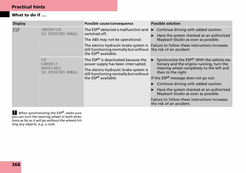
Practical hints
What to do if …
! When synchronizing the ESP®, make sure you can turn the steering wheel in both direc-tions as far as it will go without the wheels hit-ting any objects, e.g. a curb.
Display Possible cause/consequence Possible solution
ESP INOPERATIVESEE OPERATORS MANUAL
The ESP® detected a malfunction and switched off.
The ABS may not be operational.
The electro-hydraulic brake system is still functioning normally but without the ESP® available.
� Continue driving with added caution.
� Have the system checked at an authorized Maybach Studio as soon as possible.
Failure to follow these instructions increases the risk of an accident.
ESPCURRENTLYUNAVAILABLESEE OPERATORS MANUAL
The ESP® is deactivated because the power supply has been interrupted.
The electro-hydraulic brake system is still functioning normally but without the ESP® available.
� Synchronize the ESP®: With the vehicle sta-tionary and the engine running, turn the steering wheel completely to the left and then to the right.
If the ESP® message does not go out:
� Continue driving with added caution.
� Have the system checked at an authorized Maybach Studio as soon as possible.
Failure to follow these instructions increases the risk of an accident.
368

Practical hints
What to do if …
Display Possible cause/consequence Possible solution
FRONT PASSENGERAIRBAG ENABLEDSEEOPERATOR’S MANUAL
Front passenger front airbag is acti-vated while driving even though a child, small individual, or object be-low the system’s weight threshold is on the front passenger seat, or the front passenger seat is empty. Objects on the seat or forces acting on the seat may make the system sense sup-plemental weight.
Stop the vehicle in a safe location as soon as possible and check the front passenger seat for the following:
� Apply the parking brake.
� Switch off the ignition (� page 60).
� Open the front passenger door.
� Remove child and child restraint from front passenger seat and properly secure the child in rear seat employing the child restraint if necessary.
� Make sure that no objects which apply forces to the seat are present (e.g. objects such as books, briefcases etc. lodged be-hind or around the seat, head restraints pushing against roof etc.). The system may recognize such forces as supplemental weight and sense that an occupant on the front passenger seat is of a greater weight than actually present.
� Keep the seat unoccupied, close the front passenger door and turn on the ignition (� page 60).
(Continued on next page)
369

Practical hints
What to do if …
Display Possible cause/consequence Possible solution
Monitor the PASSENGER AIRBAG OFF indicator lamp on the cen-ter console (� page 25) and the multifunction display in the in-strument cluster (� page 24) for the following:
With the seat unoccupied and the ignition turned on,
� the PASSENGER AIRBAG OFF indicator lamp on the center console should illuminate and remain illuminated, indicating that the OCS (� page 88) has deactivated the front passenger front airbag.
� the message FRONT PASSENGER AIRBAG ENABLED SEE OPERATOR’S MANUAL or the message FRONT PASSENGER AIRBAG DISABLED SEE OPERATOR’S MANUAL should not appear in the multifunction display at any time the seat is unoccupied. Wait at least 60 seconds for the system to complete the necessary check cycles and to make sure neither message appears in the multifunction display.
If above conditions are met, you can occupy the front passenger seat again. Depending on the front passenger classification sensed by the OCS (� page 88), the PASSENGER AIRBAG OFF indi-cator lamp will remain illuminated or go out.
If above conditions are not met, the system is not working prop-erly. Have the system checked as soon as possible by an autho-rized Maybach Studio.
370

Practical hints
What to do if …
Display Possible cause/consequence Possible solution
FRONT PASSENGERAIRBAG DISABLEDSEEOPERATOR’S MANUAL
Front passenger front air bag is deac-tivated while driving even though an adult or someone larger than a small individual is occupying the front pas-senger seat. Forces acting on the seat may make the system sense a de-crease in weight.
Stop the vehicle in a safe location as soon as possible and check the front passenger seat for the following:
� Apply the parking brake.
� Switch off the ignition (� page 60).
� Have the front passenger vacate the seat and exit the vehicle.
� Adjust the seat in a height position (� page 63).
� Make sure that no objects which apply forces to the seat are present (e.g. objects such as books, briefcases etc. lodged un-derneath, behind or around the seat). Such forces may cause the system to sense that an occupant of a lesser weight than actually present is on the front passenger seat.
� Keep the seat unoccupied, close the front passenger door and turn on the ignition (� page 60).
(Continued on next page)
371

Practical hints
What to do if …
Display Possible cause/consequence Possible solution
Monitor the PASSENGER AIRBAG OFF indicator lamp on the cen-ter console (� page 25) and the multifunction display in the in-strument cluster (� page 24) for the following:
With the seat unoccupied and the ignition turned on,
� the PASSENGER AIRBAG OFF indicator lamp on the center console should illuminate and remain illuminated, indicating that the OCS (� page 88) has deactivated the front passenger front airbag.
� the message FRONT PASSENGER AIRBAG ENABLED SEE OPERATOR’S MANUAL or the message FRONT PASSENGER AIRBAG DISABLED SEE OPERATOR’S MANUAL should not appear in the multifunction display at any time the seat is unoccupied. Wait at least 60 seconds for the system to complete the necessary check cycles and to make sure neither message appears in the multifunction display.
If above conditions are met, you can occupy the front passenger seat again. Depending on the front passenger classification sensed by the OCS (� page 88), the PASSENGER AIRBAG OFF indi-cator lamp will remain illuminated or go out.
If above conditions are not met, the system is not working prop-erly. Have the system checked as soon as possible by an autho-rized Maybach Studio.
Warning! G
If the PASSENGER AIRBAG OFF indicator lamp remains illuminated with an
adult occupant on the front passenger seat even after performing the above correc-tive steps, do not have any passenger use the front passenger seat until the system has been repaired.
372

Practical hints
What to do if …
Display Possible cause/consequence Possible solution
MOVE SELECTOR LEVERTO P
You have tried to turn off the engine with the KEYLESS-GO** start/stop button (� page 61) with the gear se-lector lever not in P.
� Place the gear selector lever in position P.
SRS MALFUNCTIONVISIT WORKSHOP
The system is malfunctioning. � Drive with added caution to the nearest authorized Maybach Studio.
TELE AID MALFUNCTIONDRIVE TO WORKSHOP
One or more main functions of the Tele Aid system are malfunctioning.
� Have the Tele Aid system checked by an au-thorized Maybach Studio.
373

Practical hints
What to do if …
Display Possible cause/consequence Possible solution
TIRE PRES. MONITOR REACTIVATE AFTERCORRECTING PRES.
There was a tire inflation pressure warning message.
The yellow warning lamp for the tire inflation pressure monitor lights up and you have not reactivated the sys-tem since the last tire inflation pres-sure check.
� Reactivate the tire inflation pressure moni-tor after correcting the tire inflation pres-sure values (� page 323).
TIRE PRESSURE DISPLAY ONLY AVAILABLE WHEN IGNITION IS ON
� Switch on the ignition (� page 60).
TIRE PRES. MONITORREACTIVATED
The tire inflation pressure monitor is using the current pressure values as the basis for monitoring.
Warning! G
Do not drive with a flat tire. A flat tire af-fects the ability to steer or brake the vehi-cle.
You may lose control of the vehicle. Con-tinued driving with a flat tire will cause ex-cessive heat build-up and possibly a fire.
374

Practical hints
What to do if …
Display Possible cause/consequence Possible solution
TIRE PRES. MONITORCURRENTLYUNAVAILABLE
The tire inflation pressure monitor is temporarily inoperative because
� an additional wheel sensor is in the vehicle
� the maximum temperature of the wheel sensor has been exceeded
� a radio source is causing interfer-ence
� unrecognized wheel sensors are installed
� Remove the additional wheel sensor from the vehicle.
As soon as the causes of the malfunction have been removed, the tire inflation pressure mon-itor automatically becomes active again.
TIRE PRES. MONITORNOT OPERATIONALDRIVE TO WORKSHOP
The tire inflation pressure monitor or the wheel sensor is malfunctioning.
� Have the tire inflation pressure monitor checked by an authorized Maybach Studio.
A wheel without proper sensor was installed.
� Have the wheels checked.
Warning! G
Do not drive with a flat tire. A flat tire af-fects the ability to steer or brake the vehi-cle.
You may lose control of the vehicle. Con-tinued driving with a flat tire will cause ex-cessive heat build-up and possibly a fire.
375

Practical hints
What to do if …
Symbol messages
Display Possible cause/consequence Possible solution
P AIRMATICSTOP, CAR TOO LOW
The vehicle level is too low. � Wait until the vehicle level has been adjust-ed.
The message then disappears.
The vehicle level control is malfunc-tioning. In addition, the following message appears:
AIRMATIC MALFUNCTION
� Stop and press the vehicle level control but-ton to select a higher vehicle level (� page 234).
� Do not turn steering wheel too far to avoid damaging the front fenders.
� Listen for scraping noises.
� Do not exceed a speed of 50 mph (80 km/h).
� Contact an authorized Maybach Studio as soon as possible.
Failure to follow these instructions increases the risk of an accident.
AIRMATICMALFUNCTION
The Airmatic system has only limited operation.
The display for Airmatic or the Air-matic system itself is malfunctioning.
� Do not exceed a speed of 50 mph (80 km/h).
� Contact an authorized Maybach Studio as soon as possible.
AIRMATICVEHICLE RISING
Your vehicle is adjusting to your level selection.
376

Practical hints
What to do if …
Display Possible cause/consequence Possible solution
# BATTERY/ALTERNATORSTOP VEHICLE
The battery, the alternator or the electrical system control unit is mal-functioning.
The electro-hydraulic brake system requires electrical energy and there-fore has only limited operation. Con-siderably greater brake pedal force is required and the stopping distance is increased.
� Stop the vehicle in a safe location as soon as it is safe to do so. Adjust driving to be consis-tent with reduced braking responsiveness.
� Notify an authorized Maybach Studio.
Failure to follow these instructions increases the risk of accident.
� Read and observe messages about the elec-tro-hydraulic brake system in the multifunc-tion display.
The battery is no longer charging.
Possible causes:
� alternator malfunctioning
� broken poly-V-belt
Do not forget that the brake system requires electrical energy and may be operating with restricted capability. Considerably greater brake pedal force is required and the stopping distance is increased.
� Stop immediately in a safe location or as soon as it is safe to do so and check the poly-V-belt.
If it is broken:
� Do not continue to drive. Otherwise the en-gine will overheat due to an inoperative wa-ter pump which may result in damage to the engine. Notify an authorized Maybach Studio.
If it is intact:
� Drive immediately to the nearest authorized Maybach Studio. Adapt driving to be consis-tent with reduced braking responsiveness.
� Read and observe messages about the elec-tro-hydraulic brake system in the multifunc-tion display.
! RELEASEPARKING BRAKE
You are driving with the parking brake engaged.
� Release the parking brake (� page 72).
377

Practical hints
What to do if …
Display Possible cause/consequence Possible solution
T BRAKE MALFUNCTIONSTOP VEHICLE
The electro-hydraulic brake system is in the emergency operation mode. Considerably greater brake pedal force is required and the stopping distance is increased.
The maximum speed is limited to 55 mph (90 km/h).
� Stop the vehicle in a safe location as soon as it is safe to do so.
� Apply the parking brake (� page 77).
� Do not drive any further.
� Prevent the vehicle from rolling away by blocking wheels with wheel chocks or other sizable, heavy objects (� page 414).
� Contact an authorized Maybach Studio or call for Roadside Assistance (� page 285).
Warning! G
Driving while these messages are displayed can result in an accident. Have your brake system checked immediately.
If the electro-hydraulic brake system enters its emergency operation mode, the driver must apply significantly greater brake ped-al pressure and depress the pedal much further than normal to obtain braking ef-fect. If necessary, apply full pressure to the brake pedal. Brakes are only applied to the front wheels.
Stopping distance is increased!
If there is a malfunction in the electro-hy-draulic brake system, we recommend that the vehicle be transported with all wheels off the ground using flatbed or appropri-ate wheel lift/dolly equipment. A tow bar must be used if circumstances do not per-mit the use of the recommended towing methods and the vehicle requires towing with all four wheels on the ground.
Towing the vehicle with all four wheels on the ground is only permissible for distances up to 30 miles (50 km) and at a speed not to exceed 30 mph (50 km/h).
For more information, see “Towing the ve-hicle” (� page 423).
378

Practical hints
What to do if …
Display Possible cause/consequence Possible solution
; (USA only)
3 (Canada only)
REDUCED BRAKE POWERSTART ENGINE
The battery has insufficient voltage and cannot supply sufficient power to the electro-hydraulic brake system.
� Start the engine.
The message disappears when sufficient volt-age is available.
Warning! G
Inhalation of exhaust gas is hazardous to your health. All exhaust gas contains car-bon monoxide (CO), and inhaling it can cause unconsciousness and possible death. Do not run the engine in confined areas (such as a garage) which are not properly ventilated. If you think that exhaust gas fumes are entering the vehicle while driv-ing, have the cause determined and cor-rected immediately. If you must drive under these conditions, drive with at least one window fully open.
379

Practical hints
What to do if …
Display Possible cause/consequence Possible solution
; (USA only)
3 (Canada only)
REDUCED BRAKE POWERVISIT WORKSHOP
The electro-hydraulic brake system is in the emergency operation mode. Considerable greater brake pedal force is required and the stopping distance is increased.
� Continue driving with added caution.
� Adjust driving to be consistent with reduced braking responsiveness.
� Drive immediately to the nearest authorized Maybach Studio.
� Failure to follow these instructions increases the risk of accident.
Warning! G
Driving while these message is displayed can result in an accident. Have your brake system checked immediately.
If the electro-hydraulic brake system enters its emergency operation mode, the driver must apply significantly greater brake ped-al pressure and depress the pedal much further than normal to obtain braking ef-fect. If necessary, apply full pressure to the brake pedal. Brakes are only applied to the front wheels.
Stopping distance is increased!
If there is a malfunction in the electro-hy-draulic brake system, we recommend that the vehicle be transported with all wheels off the ground using flatbed or appropri-ate wheel lift/dolly equipment.
A tow bar must be used if circumstances do not permit the use of the recommended towing methods and the vehicle requires towing with all four wheels on the ground.
Towing the vehicle with all four wheels on the ground is only permissible for distances up to 30 miles (50 km) and at a speed not to exceed 30 mph (50 km/h).
For more information, see “Towing the ve-hicle” (� page 423).
380

Practical hints
What to do if …
! If you find that the brake fluid in the brake fluid reservoir has fallen to the mini-mum mark or below, have the brake system checked for brake pad thickness and leaks.
Display Possible cause/consequence Possible solution
; (USA only)
3 (Canada only)
BRAKES OVERHEATEDDRIVE CAREFULLY
The brake system is overheated due to an excessive load on the brakes.
� Relieve the load on the brake system.
� Drive more smoothly and think ahead to avoid unnecessary braking.
� When driving down slopes, shift into a lower gear to use the engine’s braking power (� page 182).
� Cautiously continue driving so that the air stream will cool down the brakes.
SERVICE BRAKEVISIT WORKSHOP
There are malfunctions, but the elec-tro-hydraulic brake system is operat-ing normally.
� Contact an authorized Maybach Studio as soon as possible.
BRAKE FLUIDPLEASE CHECK LEVEL
There is insufficient brake fluid in the reservoir.
� Risk of accident! Stop the vehicle in a safe lo-cation and notify an authorized Maybach Studio. Do not add brake fluid! This will not solve the problem.
Failure to follow these instructions increases the risk of accident.
Warning! G
Driving with the message BRAKE FLUID PLEASE CHECK LEVEL displayed can result in an accident. Have your brake system checked immediately.
Low brake fluid in the reservoir may cause the braking system to fail!
Do not add brake fluid before checking the brake system. Overfilling the brake flu-id reservoir can result in spilling brake fluid on hot engine parts and the brake fluid catching fire. You can be seriously burned.
381

Practical hints
What to do if …
! Brake pad thickness must be visually in-spected by a qualified technician at the inter-vals specified in the Maintenance Booklet.
Display Possible cause/consequence Possible solution
2 BRAKE PADWEAR
The brake pads have reached their wear limit.
� Have the brake pads replaced as soon as pos-sible at an authorized Maybach Studio.
Warning! G
Have brake pad replacement and other work on the electro-hydraulic brake sys-tem carried out by qualified technicians only. Contact your Maybach Studio for fur-ther information. The electro-hydraulic brake system must be deactivated prior to working on the system. High pressure is in-termittently built up in the system as part of its automatic self-test. In addition, the system is automatically activated when the vehicle is unlocked by remote control, when the driver or passenger door is opened, when the SmartKey in the starter switch is turned to position 1, when the brake pedal is depressed or when the park-ing brake is released.
Failure to deactivate the system prior to maintenance will cause brake pistons to extend and brake fluid to leak, which may result in injuries (contusions and acid burns), see “Electro-hydraulic brake sys-tem” (� page 107).
382

Practical hints
What to do if …
! Do not ignore the low engine coolant lev-el warning. Extended driving with the mes-sage and symbol displayed may cause serious engine damage not covered by the Maybach Limited Warranty.
Do not drive without a sufficient amount of coolant in the cooling system. The engine will overheat, causing major engine damage.
Display Possible cause/consequence Possible solution
B TOP UP COOLANTSEE OPERATORS MANUAL
The coolant level is too low. � Add coolant (� page 310).
Comply with all warnings while doing so.
� If you have to add coolant frequently, have the cooling system checked by an authorized Maybach Studio.
Warning! G
Do not spill antifreeze on hot engine parts. Antifreeze contains ethylene glycol which may burn if it comes into contact with hot engine parts. You could be seriously burned.
383
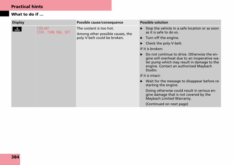
Practical hints
What to do if …
Display Possible cause/consequence Possible solution
D COOLANTSTOP, TURN ENG. OFF
The coolant is too hot.
Among other possible causes, the poly-V-belt could be broken.
� Stop the vehicle in a safe location or as soon as it is safe to do so.
� Turn off the engine.
� Check the poly-V-belt.
If it is broken:
� Do not continue to drive. Otherwise the en-gine will overheat due to an inoperative wa-ter pump which may result in damage to the engine. Contact an authorized Maybach Studio.
If it is intact:
� Wait for the message to disappear before re-starting the engine.
Doing otherwise could result in serious en-gine damage that is not covered by the Maybach Limited Warranty.
(Continued on next page)
384

Practical hints
What to do if …
During severe operating conditions, e.g. stop-and-go traffic, the coolant temper-ature may rise close to approximately 248°F (120°C).
! The engine should not be operated with the coolant temperature above 248°F (120°C). Doing so may cause serious engine damage which is not covered by the Maybach Limited Warranty.
Display Possible cause/consequence Possible solution
� Observe the coolant temperature gauge (� page 23).
If the coolant temperature rises again:
� Contact an authorized Maybach Studio as soon as possible.
Warning! G
� Driving when your engine is overheat-ed can cause some fluids which may have leaked into the engine compart-ment to catch fire. You could be seriously burned.
� Steam from an overheated engine can cause serious burns which can occur just by opening the hood. Stay away from the engine if you see or hear steam coming from it.
Stop the vehicle in a safe location away from other traffic. Turn off the engine, get out of the vehicle and do not stand near the vehicle until the engine has cooled down.
385

Practical hints
What to do if …
Display Possible cause/consequence Possible solution
D The cooling fan for the coolant is mal-functioning.
� Observe the coolant temperature gauge (� page 155).
� Have the fan replaced as soon as possible.
Î CRUISE CONTROLINOPERATIVE
Cruise control or Distronic** is mal-functioning.
� Have cruise control or Distronic** checked by an authorized Maybach Studio.
± DISPLAY MALFUNCTIONVISIT WORKSHOP
Certain electronic systems are unable to relay information to the control system. The following systems may have failed:
� Coolant temperature display
� Tachometer
� Cruise control display
� Have the electronic systems checked by an authorized Maybach Studio.
VISIT WORKSHOP There may be a malfunction in the:
� Fuel injection system
� Ignition system
� Exhaust system
� Fuel system
� Contact an authorized Maybach Studio as soon as possible.
G DISPLAY MALFUNCTIONVISIT WORKSHOP
The displays for several systems have malfunctioned. Some systems them-selves may also have malfunctioned.
� Continue driving with added caution.
� Contact an authorized Maybach Studio as soon as possible.
Failure to follow these instructions increases the risk of accident.
386

Practical hints
What to do if …
When the message:
ADD 1.0 QT. OIL
AT GAS STATION
(Canada: 1.0 LITER)
appears while the engine is running and at operating temperature, the engine oil level has dropped to approximately the minimum level.
When this occurs, the warning will first come on intermittently and then stay on if the oil level drops further.
If no oil leaks are noted, continue to drive to the nearest service station where the engine oil should be topped to the required level with an approved engine oil.For information on approved engine oils, refer to the Factory Approved Service Products pamphlet (USA only) or contact an authorized Maybach Studio.
! The engine oil level warnings should not be ignored. Extended driving with the symbol displayed could result in serious engine dam-age that is not covered by the Maybach Limited Warranty.
Display Possible cause/consequence Possible solution
N ENGINE OIL LEVELVISIT WORKSHOP
The engine oil has dropped to a criti-cal level.
� Check the engine oil level (� page 309) and add oil as required.
� If you must add engine oil frequently, have the engine checked for possible leaks.
There is water in the oil. � Have the oil checked.
387

Practical hints
What to do if …
Display Possible cause/consequence Possible solution
N ADD 1.0 QT. OILAT GAS STATION
(Canada: 1.0 LITER)
The engine oil level is too low. � Add engine oil (� page 310) and check the engine oil level (� page 309).
ENGINE OIL LEVELREDUCE OIL LEVEL
You have added too much engine oil. There is a risk of damaging the en-gine or the catalytic converter.
� Have oil siphoned or drained off. Observe all legal requirements with respect to its dispos-al.
ENGINE OIL LEVELSTOP, TURN ENG. OFF
There is no oil in the engine. There is a danger of engine damage.
� Carefully bring the vehicle to a halt as soon as possible.
� Turn off the engine.
� Add engine oil.
ENGINE OIL LEVELCANNOT BE MEASURED
The measuring system is malfunction-ing.
� Have the measuring system checked by an au-thorized Maybach Studio.
_ ENTRY POSITIONDO NOT DRIVE
Seat, mirrors and steering wheel have not yet moved to their preset driving positions.
� Wait until the seat, mirrors and steering wheel have moved to their driving positions.
The message will disappear.
Y You are driving with the hood open. � Stop the vehicle in a safe location as soon as it is safe to do so.
� Close the hood (� page 307).
There is otherwise danger of an accident.
Ê The trunk is open. � Close the trunk.
V You are attempting to drive with one or more doors open.
� Close the doors.
388

Practical hints
What to do if …
Display Possible cause/consequence Possible solution
F KEYCHECK BATTERY
The SmartKey with KEYLESS-GO** batteries are discharged.
� Replace the batteries (� page 405).
KEYNOT RECOGNIZED
The SmartKey with KEYLESS-GO** is not recognized while the engine is running because
� the SmartKey with KEYLESS-GO** is not in the vehicle
� there is strong radio-frequency in-terference
� Stop the vehicle in a safe location as soon as it is safe to do so.
� Search for the SmartKey with KEYLESS-GO**.Otherwise the vehicle cannot be centrally locked nor can the engine be started again after the engine is stopped.
KEYNOT RECOGNIZED
The SmartKey with KEYLESS-GO** is momentarily not recognized.
� Change the position of the SmartKey with KEYLESS-GO** in the vehicle.
� Operate the vehicle with the SmartKey with KEYLESS-GO** in the starter switch if neces-sary.
KEYSTILL IN VEHICLE
The SmartKey with KEYLESS-GO** left in the vehicle was recognized while locking the vehicle from the outside.
� Take the SmartKey with KEYLESS-GO** out of the vehicle.
AUTOM. LIGHT ONREMOVE KEY
SmartKey in starter switch position 1 or 2.
� Remove the SmartKey from the starter switch.
LIGHTS OFF ORREMOVE KEY
The exterior lamp switch is set to U and you have forgotten to take out the SmartKey. The parking lamps re-main switched on.
� Switch off the headlamps (� page 142).
or
� Remove the SmartKey from the starter switch.
389

Practical hints
What to do if …
Display Possible cause/consequence Possible solution
F REMOVE KEY You have forgotten to remove the SmartKey.
� Remove the SmartKey from the starter switch.
REPLACE KEY The SmartKey is malfunctioning. � Contact an authorized Maybach Studio as soon as possible.
. AUTO-LIGHTINOPERATIVE
The light sensor is malfunctioning. The headlamps switch on automatically.
� In the control system, set lamp operation to manual (� page 173).
� Switch on headlamps using the exterior lamp switch.
� Contact an authorized Maybach Studio as soon as possible.
TURN OFF LIGHTS You have removed the SmartKey from the starter switch, opened the driver’s door and left the headlamps on or removed the SmartKey with KEYLESS-GO** from the vehicle and left the headlamps on.
� Turn the exterior lamp switch to M (� page 142).
ACTIVE HDLMP MALF. DRIVE TO WORKSHOP
The active Bi-Xenon headlamps have malfunctioned several times in suc-cession.
� Contact an authorized Maybach Studio as soon as possible.
ACTIVE HEADLAMPSUNOPERATIVE
The active Bi-Xenon headlamps are malfunctioning.
� Contact an authorized Maybach Studio as soon as possible.
390
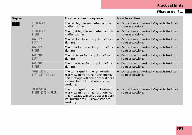
Practical hints
What to do if …
Display Possible cause/consequence Possible solution
. HIGH BEAMLEFT
The left high beam flasher lamp is malfunctioning.
� Contact an authorized Maybach Studio as soon as possible.
HIGH BEAMRIGHT
The right high beam flasher lamp is malfunctioning.
� Contact an authorized Maybach Studio as soon as possible.
LOW BEAMLEFT
The left low beam lamp is malfunc-tioning.
� Contact an authorized Maybach Studio as soon as possible.
LOW BEAMRIGHT
The right low beam lamp is malfunc-tioning.
� Contact an authorized Maybach Studio as soon as possible.
FOGLAMPLEFT
The left front fog lamp is malfunc-tioning.
� Contact an authorized Maybach Studio as soon as possible.
FOGLAMPRIGHT
The right front fog lamp is malfunc-tioning.
� Contact an authorized Maybach Studio as soon as possible.
TURN SIGNALLEFT SIDE MIRROR
The turn signal in the left exterior rear view mirror is malfunctioning. This message will only appear if a crit-ical number of LEDs have stopped working.
� Contact an authorized Maybach Studio as soon as possible.
TURN SIGNALRIGHT SIDE MIRROR
The turn signal in the right exterior rear view mirror is malfunctioning. This message will only appear if a crit-ical number of LEDs have stopped working.
� Contact an authorized Maybach Studio as soon as possible.
391
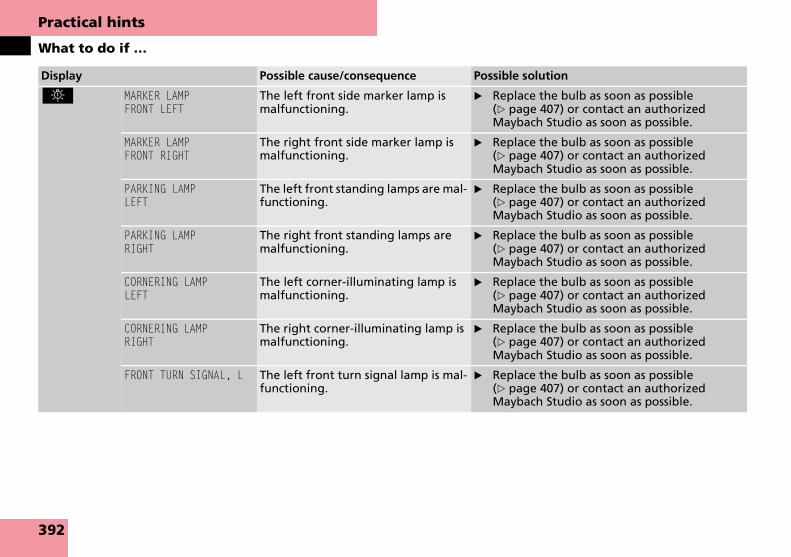
Practical hints
What to do if …
Display Possible cause/consequence Possible solution
. MARKER LAMPFRONT LEFT
The left front side marker lamp is malfunctioning.
� Replace the bulb as soon as possible (� page 407) or contact an authorized Maybach Studio as soon as possible.
MARKER LAMPFRONT RIGHT
The right front side marker lamp is malfunctioning.
� Replace the bulb as soon as possible (� page 407) or contact an authorized Maybach Studio as soon as possible.
PARKING LAMPLEFT
The left front standing lamps are mal-functioning.
� Replace the bulb as soon as possible (� page 407) or contact an authorized Maybach Studio as soon as possible.
PARKING LAMPRIGHT
The right front standing lamps are malfunctioning.
� Replace the bulb as soon as possible (� page 407) or contact an authorized Maybach Studio as soon as possible.
CORNERING LAMPLEFT
The left corner-illuminating lamp is malfunctioning.
� Replace the bulb as soon as possible (� page 407) or contact an authorized Maybach Studio as soon as possible.
CORNERING LAMPRIGHT
The right corner-illuminating lamp is malfunctioning.
� Replace the bulb as soon as possible (� page 407) or contact an authorized Maybach Studio as soon as possible.
FRONT TURN SIGNAL, L The left front turn signal lamp is mal-functioning.
� Replace the bulb as soon as possible (� page 407) or contact an authorized Maybach Studio as soon as possible.
392

Practical hints
What to do if …
Display Possible cause/consequence Possible solution
. FRONT TURN SIGNAL, R The right front turn signal lamp is malfunctioning.
� Replace the bulb as soon as possible (� page 407) or contact an authorized Maybach Studio as soon as possible.
BRAKE LAMP-LEFTAUXILIARY LAMP ON
The left brake lamp is malfunction-ing. A substitute bulb is being used.
� Contact an authorized Maybach Studio as soon as possible.
BRAKE LAMP-RIGHTAUXILIARY LAMP ON
The right brake lamp is malfunction-ing. A substitute bulb is being used.
� Contact an authorized Maybach Studio as soon as possible.
3RD BRAKE LAMP The high mounted brake lamp is mal-functioning.
� Contact an authorized Maybach Studio as soon as possible.
REAR FOGLAMP The rear fog lamp is malfunctioning. � Contact an authorized Maybach Studio as soon as possible.
LICENSE PLATE LAMPLEFT
The left license plate lamp is malfunc-tioning.
� Replace the bulb as soon as possible (� page 407) or contact an authorized Maybach Studio as soon as possible.
LICENSE PLATE LAMPRIGHT
The right license plate lamp is mal-functioning.
� Replace the bulb as soon as possible (� page 407) or contact an authorized Maybach Studio as soon as possible.
REVERSE LAMPLEFT
The left reverse lamp is malfunction-ing.
� Contact an authorized Maybach Studio as soon as possible.
REVERSE LAMPRIGHT
The right reverse lamp is malfunc-tioning.
� Contact an authorized Maybach Studio as soon as possible.
393
Practical hints
What to do if …
Display Possible cause/consequence Possible solution
. PARKING LAMP-LEFTAUXILIARY LAMP ON
The left rear standing lamps are mal-functioning. A substitute bulb is be-ing used.
� Contact an authorized Maybach Studio as soon as possible.
PARKING LAMP-RIGHTAUXILIARY LAMP ON
The right rear standing lamps are malfunctioning. A substitute bulb is being used.
� Contact an authorized Maybach Studio as soon as possible.
TAIL LAMP-LEFTAUXILIARY LAMP ON
The left tail lamp is malfunctioning. A substitute bulb is being used.
� Contact an authorized Maybach Studio as soon as possible.
TAIL LAMP-RIGHTAUXILIARY LAMP ON
The right tail lamp is malfunctioning. A substitute bulb is being used.
� Contact an authorized Maybach Studio as soon as possible.
REAR TURN SIGNAL, LAUXILIARY LAMP ON
The left rear turn signal lamp is mal-functioning. A substitute bulb is be-ing used.
� Contact an authorized Maybach Studio as soon as possible.
REAR TURN SIGNAL, RAUXILIARY LAMP ON
The right rear turn signal lamp is mal-functioning. A substitute bulb is be-ing used.
� Contact an authorized Maybach Studio as soon as possible.
394

Practical hints
What to do if …
Display Possible cause/consequence Possible solution
_ STEERING GEAR OILPLEASE CHECK
The steering oil has dropped to a crit-ical level.
� Contact an authorized Maybach Studio as soon as possible.
L TELE AID BATTERYINOPERATIVE
The emergency power battery for the Tele Aid system is malfunctioning. If the vehicle battery is also discharged, Tele Aid will not be operational.
� Have the Tele Aid system checked by an au-thorized Maybach Studio.
TELE AIDNOT ACTIVATED
You do not have a Tele Aid service contract or you have not extended your existing one.
� Obtain a Tele Aid service contract or have your existing one extended in an authorized Maybach Studio.
\ FUEL FILLER FLAPOPEN
A loss of pressure has been detected in the fuel system. The fuel cap may not be closed properly or the fuel sys-tem may be leaky.
� Check the fuel cap (� page 305).
If it is not closed properly:
� Close the fuel cap.
If it is closed properly:
� Have the fuel system checked by an autho-rized Maybach Studio.
W WASHER FLUIDPLEASE TOP UP
The fluid level has dropped to about 1/3 of total reservoir capacity.
� Add washer fluid (� page 311).
395

Practical hints
What to do if …
Display Possible cause/consequence Possible solution
H TIRE PRESSUREPLEASE CORRECT
The pressure is low in one or more tires.
� Check and correct tire inflation pressure as required (� page 321).
TIRE PRESSURECAUTION, TIRE PRES.
One or more tires is deflating. � Carefully bring the vehicle to a halt, avoiding abrupt steering and braking maneuvers. Ob-serve the traffic situation around you.
� Change the damaged wheel (� page 413).
� Have the damaged wheel repaired or re-placed at an authorized Maybach Studio.
TIRE PRESSURECHECK TIRES
The tire pressure in one or more tires is already below the minimum value.
The tire pressure in one or more tires is low.
� Carefully bring the vehicle to a halt, avoiding abrupt steering and braking maneuvers. Ob-serve the traffic situation around you.
� Check the tires. If no damage visible, check and correct tire inflation pressure as re-quired.
� If necessary, change the damaged wheel (� page 413).
� Have the damaged wheel repaired or re-placed at an authorized Maybach Studio.
Warning! G
Do not drive with a flat tire. A flat tire affects the ability to steer or brake the ve-hicle.
You may lose control of the vehicle. Con-tinued driving with a flat tire will cause ex-cessive heat build-up and possibly a fire.
396

Practical hints
What to do if …
Display Possible cause/consequence Possible solution
H TIRE PRESSURE, LFCAUTION, TIRE PRES.
The left front tire is deflating. � Carefully bring the vehicle to a halt, avoiding abrupt steering and braking maneuvers. Ob-serve the traffic situation around you.
� Change the wheel (� page 413).
� Have the damaged wheel repaired or re-placed at an authorized Maybach Studio.
TIRE PRESSURE, LFCHECK TIRES
The left front tire inflation pressure is low.
� Carefully bring the vehicle to a halt.
� Check the tires. If no damage visible, check and correct tire inflation pressure as required (� page 321).
� If necessary, change the wheel (� page 413).
� Have the damaged wheel repaired or re-placed at an authorized Maybach Studio.
TIRE PRESSURE, RFCAUTION, TIRE PRES.
The right front tire is deflating. � Carefully bring the vehicle to a halt, avoiding abrupt steering and braking maneuvers. Ob-serve the traffic situation around you.
� Change the wheel (� page 413).
� Have the damaged wheel repaired or re-placed at an authorized Maybach Studio.
Warning! G
Do not drive with a flat tire. A flat tire affects the ability to steer or brake the ve-hicle.
You may lose control of the vehicle. Con-tinued driving with a flat tire will cause ex-cessive heat build-up and possibly a fire.
397

Practical hints
What to do if …
Display Possible cause/consequence Possible solution
H TIRE PRESSURE, RFCHECK TIRES
The right front tire inflation pressure is low.
� Carefully bring the vehicle to a halt.
� Check the tires. If no damage visible, check and correct tire inflation pressure as required (� page 321).
� If necessary, change the wheel (� page 413).
� Have the damaged wheel repaired or re-placed at an authorized Maybach Studio.
TIRE PRESSURE, LRCAUTION, TIRE PRES.
The left rear tire is deflating. � Carefully bring the vehicle to a halt, avoiding abrupt steering and braking maneuvers. Ob-serve the traffic situation around you.
� Change the wheel (� page 413).
� Have the damaged wheel repaired or re-placed at an authorized Maybach Studio.
TIRE PRESSURE, LRCHECK TIRES
The left rear tire inflation pressure is low.
� Carefully bring the vehicle to a halt.
� Check the tires. If no damage visible, check and correct tire inflation pressure as required (� page 321).
� If necessary, change the wheel (� page 413).
� Have the damaged wheel repaired or re-placed at an authorized Maybach Studio.
Warning! G
Do not drive with a flat tire. A flat tire affects the ability to steer or
brake the vehicle.
You may lose control of the vehicle. Con-tinued driving with a flat tire will cause ex-cessive heat build-up and possibly a fire.
398

Practical hints
What to do if …
Display Possible cause/consequence Possible solution
H TIRE PRESSURE, RRCAUTION, TIRE PRES.
The right rear tire is deflating. � Carefully bring the vehicle to a halt, avoiding abrupt steering and braking maneuvers. Ob-serve the traffic situation around you.
� Change the wheel (� page 413).
� Have the damaged wheel repaired or re-placed at an authorized Maybach Studio.
TIRE PRESSURE, RRCHECK TIRES
The right rear tire inflation pressure is low.
� Carefully bring the vehicle to a halt.
� Check the tires. If no damage visible, check and correct tire inflation pressure as required (� page 321).
� If necessary, change the wheel (� page 413).
� Have the damaged wheel repaired or re-placed at an authorized Maybach Studio.
Warning! G
Do not drive with a flat tire. A flat tire affects the ability to steer or brake the ve-hicle.
You may lose control of the vehicle. Con-tinued driving with a flat tire will cause ex-cessive heat build-up and possibly a fire.
399
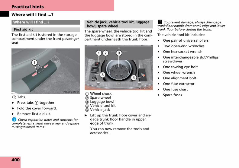
Practical hints
Where will I find ...?
The first aid kit is stored in the storage compartment under the front passenger seat.
1 Tabs
� Press tabs 1 together.
� Fold the cover forward.
� Remove first aid kit.
i Check expiration dates and contents for completeness at least once a year and replace missing/expired items.
The spare wheel, the vehicle tool kit and the luggage bowl are stored in the com-partment underneath the trunk floor.
1 Wheel chock2 Spare wheel3 Luggage bowl4 Vehicle tool kit5 Vehicle jack
� Lift up the trunk floor cover and en-gage trunk floor handle in upper edge of trunk.
You can now remove the tools and accessories.
! To prevent damage, always disengage trunk floor handle from trunk edge and lower trunk floor before closing the trunk.
The vehicle tool kit includes:
� One pair of universal pliers
� Two open-end wrenches
� One hex-socket wrench
� One interchangeable slot/Phillips screwdriver
� One towing eye bolt
� One wheel wrench
� One alignment bolt
� One fuse extractor
� One fuse chart
� Spare fuses
Where will I find ...?
First aid kit
Vehicle jack, vehicle tool kit, luggage bowl, spare wheel
400

Practical hints
Unlocking/locking in an emergency
If you are unable to unlock the vehicle using the SmartKey or KEYLESS-GO**, open the driver’s door and the trunk us-ing the mechanical key, see “Anti-theft alarm system” (� page 110).
i Unlocking the vehicle with the mechani-cal key and opening the driver’s door or the trunk with the mechanical key will trigger the anti-theft alarm system.
To cancel the alarm: Insert the SmartKey or SmartKey with KEYLESS-GO** in the starter switch.
Removing the mechanical key
1 Mechanical key locking tab2 Mechanical key
� Move locking tab 1 in direction of arrow.
� Slide mechanical key 2 out of the housing.
Unlocking the driver’s door
� Insert mechanical key 2 into the driver’s door lock until it stops.
� Turn the mechanical key 2 counter-clockwise to position 1 until the lock-ing knob moves up.
The driver’s door is unlocked.
� Pull the door handle to open the driv-er’s door.
Unlocking/locking in an emergency
Unlocking the vehicle
1 Unlocking
2 Mechanical key
401

Practical hints
Unlocking/locking in an emergency
Unlocking and opening the trunk
A minimum height clearance of 6.2 ft (1.89 m) is required to open the trunk lid.
� Insert the mechanical key 1 into the trunk lid lock until it stops.
� Turn the mechanical key 1 counter-clockwise to position 2.
The trunk unlocks.
� Pull on handle 3.
The trunk opens.
! The trunk lid swings open automatically. Always make sure there is sufficient overhead clearance.
� Turn the mechanical key 1 back and remove it from the trunk lid lock.
If you cannot lock the vehicle with the SmartKey or KEYLESS-GO**, do the fol-lowing:
� Close the front passenger door, the rear doors and the trunk.
i If you cannot close the trunk with the re-mote trunk opening/closing switch, lower the trunk lid manually and close it with hands placed flat on the trunk lid until it is engaged in its lock.
� Press the central locking switch on the center console (� page 129).
� Check to see whether the locking knobs on the doors have moved down.
� If necessary, push them down manu-ally.
� Remove the mechanical key from the SmartKey (� page 401).
� Check whether the trunk is locked.
� If necessary, lock the trunk with the mechanical key (� page 127).
Except for the driver’s door, the vehi-cle should now be locked.
� Insert the mechanical key 2 into the driver’s door lock until it stops.
� Turn the mechanical key 2 clockwise to position 1 until the locking knob moves down.
The driver’s door is locked.
i This procedure does not arm the anti-theft alarm system, nor does it lock the fuel filler flap.
1 Mechanical key
2 Unlocking in an emergency
3 Handle
Locking the vehicle
1 Locking
2 Mechanical key
402

Practical hints
Opening/closing in an emergency
You can open or close the tilt/sliding sun-roof manually should an electrical mal-function occur.
The tilt/sliding sunroof roof drive is locat-ed behind the cover on the overhead control panel.
1 Cover
� Remove the SmartKey from the start-er switch.
Vehicles with SmartKey with KEYLESS-GO**:
� Turn off the engine by pressing the KEYLESS-GO** button on the gear se-lector lever once (� page 78).
� Open the driver’s door (this puts the starter switch in position 0, same as with the SmartKey removed from the starter switch). The driver’s door then can be closed again.
� Pull cover 1 off at the location marked by the arrow.
2 Crank
� Remove crank 2 from the Operator’s Manual pouch.
� Insert crank 2 through hole.
� Turn crank 2 clockwise to:
� slide roof closed
� raise roof at the rear
� Turn crank 2 counterclockwise to:
� slide roof open
� lower roof at the rear
i Turn crank 2 slowly and smoothly.
The tilt/sliding sunroof must be synchronized after being operated manually (� page 213).
Opening/closing in an emergency
Power tilt/sliding sunroof (Maybach 57)
403
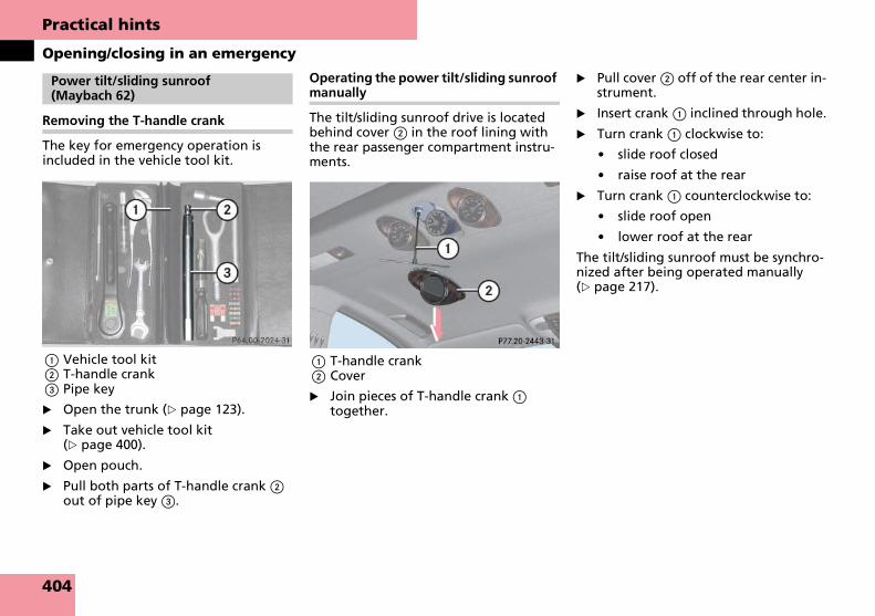
Practical hints
Opening/closing in an emergency
Removing the T-handle crank
The key for emergency operation is included in the vehicle tool kit.
1 Vehicle tool kit2 T-handle crank3 Pipe key
� Open the trunk (� page 123).
� Take out vehicle tool kit (� page 400).
� Open pouch.
� Pull both parts of T-handle crank 2 out of pipe key 3.
Operating the power tilt/sliding sunroof manually
The tilt/sliding sunroof drive is located behind cover 2 in the roof lining with the rear passenger compartment instru-ments.
1 T-handle crank2 Cover
� Join pieces of T-handle crank 1 together.
� Pull cover 2 off of the rear center in-strument.
� Insert crank 1 inclined through hole.
� Turn crank 1 clockwise to:
� slide roof closed
� raise roof at the rear
� Turn crank 1 counterclockwise to:
� slide roof open
� lower roof at the rear
The tilt/sliding sunroof must be synchro-nized after being operated manually (� page 217).
Power tilt/sliding sunroof (Maybach 62)
404

Practical hints
Replacing SmartKey batteries
If the batteries in the SmartKey or SmartKey with KEYLESS-GO** are dis-charged, the vehicle can only be locked or unlocked using the mechanical key (� page 401). It is recommended to have the batteries replaced at an authorized Maybach Studio.
Batteries contain materials that can harm the environment if disposed of im-properly. Recycling of batteries is the preferred method of disposal. Many states require sellers of batteries to ac-cept old batteries for recycling.
i When inserting the batteries, make sure they are clean and free of lint.
i When replacing batteries, always replace both batteries.
The required replacement batteries are avail-able at any Maybach Studio.
Replacement batteries: Lithium, type CR 2025 or equivalent.
� Remove the mechanical key out of the SmartKey/SmartKey with KEYLESS-GO** (� page 401).
1 Mechanical key2 Battery compartment
� Insert mechanical key 1 in direction of arrow in side opening.
� Using mechanical key 1, push the gray slide to unlatch battery compart-ment 2.
� Pull battery compartment 2 out of the housing in direction of arrow.
3 Battery4 Contact spring
� Remove the batteries 3.
� Using a lint-free cloth, insert new batteries 3 under the contact spring 4 with the plus (+) side facing up.
� Return battery compartment 2 into the housing until it locks into place.
� Slide mechanical key 1 back into the SmartKey/SmartKey with KEYLESS-GO** (� page 401).
� Check the operation of the SmartKey/SmartKey with KEYLESS-GO**.
Replacing SmartKey batteries
Warning! G
Batteries contain poisonous and corrosive substances. Therefore keep the batteries out of reach of children.
If a battery is swallowed, seek medical help immediately.
SmartKey/SmartKey with KEYLESS-GO**
405

Practical hints
Replacing bulbs
Safe vehicle operation depends on prop-er exterior lighting and signaling. It is therefore essential that all bulbs and lamp assemblies are in good working or-der at all times.
Correct headlamp adjustment is ex-tremely important. Have headlamps checked and readjusted at regular inter-vals and when a bulb has been replaced. See an authorized Maybach Studio for headlamp adjustment.
i If the headlamps or front fog lamps are fogged up on the inside as a result of high hu-midity, driving the vehicle a distance with the lights on should clear up the fogging.
i Substitute bulbs will be brought into use when the following lamps malfunction:
� Rear turn signal lamps
� Brake lamps
� Rear parking lamps
� Tail lamps
Read and observe the messages in the multi-function display (� page 393).
Replacing bulbs
406

Practical hints
Replacing bulbs
Front lamps Rear lampsBulbs
Lamp Type
1 Additional turn signal and side marker lamp
LED
2 Turn signal lamp SAE J573 2357 A 12.8 V-30CP
3 Side marker lamp W 5 W
4 Low beam and high beam lamp (active head-lamps)
Xenon1 D2S-35 W
1 Bi-Xenon headlamps: For safety reasons (high voltage), do not replace the Xenon bulb yourself. See an authorized Maybach Studio.
5 Front fog lamp H3 55 W
6 Corner-illuminat-ing lamp
H3 55 W
7 Parking and standing lamp
W 5 W Blue
8 High beam flasher H7-55 W
Lamp Type
9 High mounted brake lamp
LED
a License plate lamp C 5 W
b Brake lamp LED
Tail, parking and standing lamp
LED
Side marker lamp LED
Backup lamp H 24 W
Rear fog lamp, (driver’s side only)
LED
Turn signal lamp LED
407
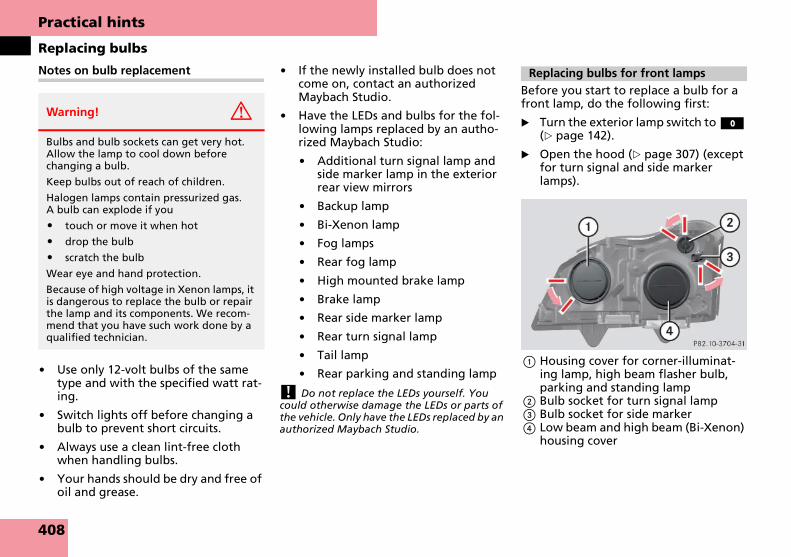
Practical hints
Replacing bulbs
Notes on bulb replacement
� Use only 12-volt bulbs of the same type and with the specified watt rat-ing.
� Switch lights off before changing a bulb to prevent short circuits.
� Always use a clean lint-free cloth when handling bulbs.
� Your hands should be dry and free of oil and grease.
� If the newly installed bulb does not come on, contact an authorized Maybach Studio.
� Have the LEDs and bulbs for the fol-lowing lamps replaced by an autho-rized Maybach Studio:
� Additional turn signal lamp and side marker lamp in the exterior rear view mirrors
� Backup lamp
� Bi-Xenon lamp
� Fog lamps
� Rear fog lamp
� High mounted brake lamp
� Brake lamp
� Rear side marker lamp
� Rear turn signal lamp
� Tail lamp
� Rear parking and standing lamp
! Do not replace the LEDs yourself. You could otherwise damage the LEDs or parts of the vehicle. Only have the LEDs replaced by an authorized Maybach Studio.
Before you start to replace a bulb for a front lamp, do the following first:
� Turn the exterior lamp switch to M (� page 142).
� Open the hood (� page 307) (except for turn signal and side marker lamps).
1 Housing cover for corner-illuminat-ing lamp, high beam flasher bulb, parking and standing lamp
2 Bulb socket for turn signal lamp3 Bulb socket for side marker4 Low beam and high beam (Bi-Xenon)
housing cover
Warning! G
Bulbs and bulb sockets can get very hot. Allow the lamp to cool down before changing a bulb.
Keep bulbs out of reach of children.
Halogen lamps contain pressurized gas. A bulb can explode if you
� touch or move it when hot
� drop the bulb
� scratch the bulb
Wear eye and hand protection.
Because of high voltage in Xenon lamps, it is dangerous to replace the bulb or repair the lamp and its components. We recom-mend that you have such work done by a qualified technician.
Replacing bulbs for front lamps
408

Practical hints
Replacing bulbs
5 Bulb socket for high beam flasher bulb
6 Bulb socket for parking and standing lamp
7 Bulb socket for corner-illuminating lamp
Low beam and high beam bulbs
High beam flasher bulbs
� Twist housing cover 1 (� page 408) counterclockwise and pull out.
� Twist bulb socket 5 counterclock-wise and pull out.
� Push bulb into socket, turn counter-clockwise and remove.
� Insert new bulb in socket, push in and twist clockwise.
� Reinsert bulb socket 5 in lamp and twist clockwise.
� Align housing cover 1 and twist clockwise.
Parking and standing lamp bulb
� Twist housing cover 1 (� page 408) counterclockwise and pull out.
� Pull out bulb socket 6 with the bulb.
� Pull the bulb out of the bulb socket 6.
� Insert a new bulb in the socket.
� Reinstall bulb socket 6.
� Align housing cover 1 and twist clockwise.
Corner-illuminating lamps
� Twist housing cover 1 (� page 408) counterclockwise and pull out.
� Press bulb holder for corner-illumi-nating lamp 7 (� page 409) upward and to the left in direction of arrow.
� The bulb holder disengages.
� Remove bulb from lamp and pull white cable out of black cable con-nector.
� Insert cable of new bulb into black ca-ble connector.
� Insert new bulb into lamp and en-gage bulb holder for corner-illumi-nating lamp 7 into position.
� Align housing cover 1 and twist clockwise.
Warning! G
Do not remove the cover for the Bi-Xenon headlamp. Because of high voltage in Xe-non lamps, it is dangerous to replace the bulb or repair the lamp and its compo-nents. We recommend that you have such work done by a qualified technician.
409

Practical hints
Replacing bulbs
Front turn signal and side marker lamp bulb
� Turn the wheels so that the wheel at the housing you need to work on is turned inward.
This will provide easier access to the lamp cover.
� Secure the vehicle from moving by applying the parking brake and plac-ing the gear selector lever in position P.
� Make sure the engine and ignition are turned off.
8 Cover in the wheel housing trim
� Turn cover 8 counterclockwise and remove cover.
Front turn signal bulb
� Twist bulb socket 2 (� page 408) counterclockwise and pull out.
� Push bulb into socket, turn counter-clockwise and remove.
� Insert new bulb in socket, push in and twist clockwise.
� Reinsert bulb socket 2 in lamp and twist clockwise.
� Replace cover 8 (� page 410) and turn it clockwise.
Side marker lamp bulb
� Twist bulb socket 3 (� page 408) counterclockwise and pull out.
� Push bulb into socket, turn counter-clockwise and remove.
� Insert new bulb in socket, push in and twist clockwise.
� Reinsert bulb socket 3 in lamp and twist clockwise.
� Replace cover 8 (� page 410) and turn it clockwise.
1 Screws2 License plate lamp
� Turn the exterior lamp switch to M (� page 142).
� Loosen both screws 1.
� Remove license plate lamp 2.
� Replace the bulb.
� Reinstall the license plate lamp 2.
� Retighten the screws 1.
Warning! G
Before reaching into the wheel housing, make sure you have secured the vehicle from moving by applying the parking brake and placing the gear selector lever in position P. Otherwise, the vehicle may move unexpectedly. Unexpected vehicle movement while you are working near the wheel housing may cause serious personal injury and/or an accident.
License plate lamp
410
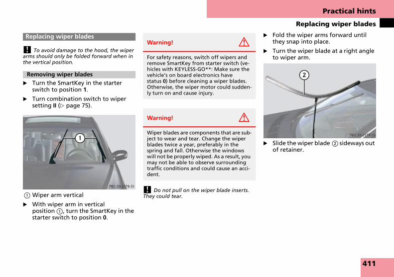
Practical hints
Replacing wiper blades
! To avoid damage to the hood, the wiper arms should only be folded forward when in the vertical position.
� Turn the SmartKey in the starter switch to position 1.
� Turn combination switch to wiper setting II (� page 75).
1 Wiper arm vertical
� With wiper arm in vertical position 1, turn the SmartKey in the starter switch to position 0.
! Do not pull on the wiper blade inserts. They could tear.
� Fold the wiper arms forward until they snap into place.
� Turn the wiper blade at a right angle to wiper arm.
� Slide the wiper blade 2 sideways out of retainer.
Replacing wiper blades
Removing wiper blades
Warning! G
For safety reasons, switch off wipers and remove SmartKey from starter switch (ve-hicles with KEYLESS-GO**: Make sure the vehicle’s on board electronics have status 0) before cleaning a wiper blades. Otherwise, the wiper motor could sudden-ly turn on and cause injury.
Warning! G
Wiper blades are components that are sub-ject to wear and tear. Change the wiper blades twice a year, preferably in the spring and fall. Otherwise the windows will not be properly wiped. As a result, you may not be able to observe surrounding traffic conditions and could cause an acci-dent.
411

Practical hints
Replacing wiper blades
� Slide the wiper blade into the cutout on the wiper arm.
� Rotate the wiper blade into position parallel to wiper arm.
� Fold the wiper arm back so that blade rests on windshield. Make sure you hold on to the wiper when folding the wiper arm back.
! Never open the hood when the wiper arm is folded forward.
Hold on to the wiper when folding the wiper arm back. If released, the force of the impact from the tensioning spring could crack the windshield.
Do not allow the wiper arms to contact the windshield glass without a wiper blade insert-ed.
Make certain that the wiper blades are prop-erly installed. Improperly installed wiper blades may cause windshield damage.
For your convenience, you should have this work carried out by an authorized Maybach Studio.
Installing wiper blades
412

Practical hints
Flat tire
� Park the vehicle in a safe distance from moving traffic on a hard, flat surface when possible.
� Turn on the hazard warning flashers.
� Turn the steering wheel so that the front wheels are in a straight ahead position.
� Set the parking brake.
� Move the gear selector lever to P.
Vehicles with SmartKey:
� Turn off the engine (� page 78).
� Remove the SmartKey from the start-er switch.
Vehicles with SmartKey with KEYLESS-GO**:
� Turn off the engine by pressing the KEYLESS-GO** button on the gear se-lector lever once (� page 79).
� Open the driver’s door (this puts the starter switch in position 0, same as with the SmartKey removed from the starter switch). The driver’s door then can be closed again.
i Open the door only when conditions are safe to do so.
� Have any passenger exit the vehicle at a safe distance from the roadway.
Spare wheel
The spare wheel rim is mounted with a full-sized tire of the same type as on the vehicle, and it is fully functional.
When you replace the vehicle’s tires, you can use the spare wheel as a regular wheel if:
� it is not more than 6 years old
� rim and tire are the same model as the regular wheels
For more information on spare wheel, see “Technical data” (� page 436).
Removing the spare wheel
� Turn the luggage bowl counterclock-wise (� page 400).
� Remove the spare wheel.
Storing the spare wheel
� Place spare wheel in wheel well and secure it with luggage bowl.
� Turn the luggage bowl clockwise to its stop.
Preparing the vehicle
� Take vehicle tool kit tray and vehicle jack out of trunk.
� Take the spare wheel out of wheel well.
Flat tire
Preparing the vehicle
Mounting the spare wheel
Warning! G
If the spare tire is more than 6 years old or is not the same model as the regular tires, have the spare tire replaced with a new tire at the nearest Maybach Studio.
Never operate the vehicle with more than one spare tire.
413
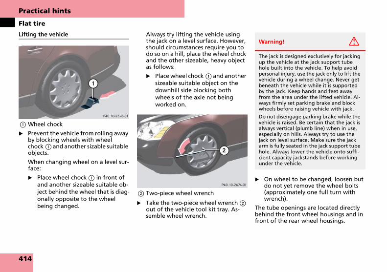
Practical hints
Flat tire
Lifting the vehicle
1 Wheel chock
� Prevent the vehicle from rolling away by blocking wheels with wheel chock 1 and another sizable suitable objects.
When changing wheel on a level sur-face:
� Place wheel chock 1 in front of and another sizeable suitable ob-ject behind the wheel that is diag-onally opposite to the wheel being changed.
Always try lifting the vehicle using the jack on a level surface. However, should circumstances require you to do so on a hill, place the wheel chock and the other sizeable, heavy object as follows:
� Place wheel chock 1 and another sizeable suitable object on the downhill side blocking both wheels of the axle not being worked on.
2 Two-piece wheel wrench
� Take the two-piece wheel wrench 2 out of the vehicle tool kit tray. As-semble wheel wrench.
� On wheel to be changed, loosen but do not yet remove the wheel bolts (approximately one full turn with wrench).
The tube openings are located directly behind the front wheel housings and in front of the rear wheel housings.
Warning! G
The jack is designed exclusively for jacking up the vehicle at the jack support tube hole built into the vehicle. To help avoid personal injury, use the jack only to lift the vehicle during a wheel change. Never get beneath the vehicle while it is supported by the jack. Keep hands and feet away from the area under the lifted vehicle. Al-ways firmly set parking brake and block wheels before raising vehicle with jack.
Do not disengage parking brake while the vehicle is raised. Be certain that the jack is always vertical (plumb line) when in use, especially on hills. Always try to use the jack on level surface. Make sure the jack arm is fully seated in the jack support tube hole. Always lower the vehicle onto suffi-cient capacity jackstands before working under the vehicle.
414

Practical hints
Flat tire
3 Jack 4 Jack support tube hole5 Ratchet
� Insert jack 3 fully into tube hole 4 up to the stop.
� Take ratchet 5 out of vehicle tool kit.
� Place ratchet 5 on jack 3 so that you can see the letters UP.
� Crank ratchet 5 up and down until the tire is a maximum of 1.2 in (3 cm) off the ground.
Removing the wheel
6 Alignment bolt
� Unscrew uppermost wheel bolt and remove.
� Replace this wheel bolt with align-ment bolt 6 supplied in the tool kit.
� Remove the remaining bolts.
! Do not place wheel bolts in sand or dirt. This could result in damage to the bolt and wheel hub threads.
� Remove the wheel.
Mounting the new wheel
� Clean contact surfaces of wheel and wheel hub.
! To avoid paint damage, place wheel flat against hub and hold it there while installing first wheel bolt.
Warning! G
Insert the jack arm fully into the jack sup-port tube hole up to the stop. Otherwise the vehicle may fall off the jack and cause personal injury or damage to the vehicle.
Warning! G
The jack is intended only for lifting the ve-hicle briefly for wheel changes. It is not suited for performing maintenance work under the vehicle.
� Never start the engine when the vehi-cle is raised.
� Never lie down under the raised vehi-cle.
Warning! G
Always replace wheel bolts that are dam-aged or rusted.
Never apply oil or grease to wheel bolts.
Damaged wheel hub threads should be re-paired immediately. Do not continue to drive under these circumstances! Contact an authorized Maybach Studio or call Roadside Assistance. ��
415

Practical hints
Flat tire
�
� Guide the spare wheel onto the alignment bolt and push it on.
� Insert wheel bolts and tighten them slightly.
� Unscrew the alignment bolt, install last wheel bolt and tighten slightly.
Lowering the vehicle
� Place ratchet on jack so that you can see the letters DOWN.
� Lower vehicle by cranking ratchet up and down until vehicle is resting fully on its own weight.
� Remove the jack.
1 - 5 Wheel bolts
� Tighten the five wheel bolts evenly, following the diagonal sequence il-lustrated (1 to 5), until all bolts are tight. Observe a tightening torque of 110 lb-ft (150 Nm).
� Before storing the jack in the trunk, it should be fully collapsed, with handle folded in.
� Place the wheel bolt wrench, chock, alignment bolt and jack back in the trunk.
Replacing jack support tube cover
� Slide tongue of cover under the up-per edge of the tube opening.
� Applying even pressure, press cover until it snaps into place. Be careful not to damage the locking tabs or clamp the plastic retaining strap.
! You can also secure the damaged wheel down into the spare wheel well in the trunk.
Do not activate the tire inflation pressure monitor (� page 321) until the depressurized tire is no longer in the vehicle.
Incorrect mounting bolts or improperly tightened mounting bolts can cause the wheel to come off. This could cause an ac-cident. Make sure you are using the correct mounting bolts.
Warning! G
Use only Genuine equipment Maybach wheel bolts. Other wheel bolts may come loose.
� Do not tighten the wheel bolts when the vehicle is raised. Otherwise the vehicle could fall off the jack.
Warning! G
Have the tightening torque checked after changing a wheel. The wheels could come loose if they are not tightened to a torque of 110 lb-ft (150 Nm).
416

Practical hints
Batteries
Your vehicle is equipped with two bat-teries:
� The starter battery (located in the en-gine compartment)
� The battery for electrical consumers (located in the trunk)
These batteries should always be suffi-ciently charged in order to achieve their rated service life. Refer to Maintenance Booklet for battery maintenance inter-vals.
If you use your vehicle mostly for short-distance trips, you will need to have the battery charge checked more frequently.
When replacing batteries, always use batteries approved by us for use on Maybach vehicles.
If you do not intend to operate your ve-hicle for an extended period of time, consult an authorized Maybach Studio about steps you need to observe.
Batteries contain materials that can harm the environment if disposed of im-properly. Recycling of batteries is the preferred method of disposal. Many states require sellers of batteries to ac-cept old batteries for recycling.
1 Negative terminal2 Starter battery3 Cover over positive terminal
BatteriesWarning! G
Observe all safety instructions and precau-tions when handling automotive batteries.
Risk of explosion.
Fire, open flames and smoking are prohibited when handling batteries. Avoid creating sparks.
Battery acid is caustic. Do not allow it to come into contact with skin, eyes or clothing.
Wear suitable protective clothing, especially gloves, apron and faceguard.
Wear eye protection.
Rinse any acid spills immedi-ately with clear water. Contact a physician if necessary.
Keep children away.
Follow the instructions in this Operator’s Manual.
417

Practical hints
Batteries
4 Cover over positive terminal5 Battery for electrical consumers6 Negative terminal
! The consumer battery located in the trunk is a valve-regulated lead acid (VRLA) battery, also referred to as “fleece” battery. Such bat-teries do not require topping-up of the elec-trolyte level. VRLA batteries therefore do not have cell caps and the battery cover is non-re-movable. Do not attempt to open the con-sumer battery as otherwise the battery will be damaged.
Even though VRLA batteries do not require topping-up of the electrolyte level and cannot be opened to check the electrolyte level, the battery condition must be checked periodical-ly by performing a battery conductance test. Refer to Maintenance Booklet for battery con-dition testing intervals.
As with any other battery, disconnect the con-sumer battery if you do not intend to operate your vehicle for an extended period of time to prevent battery discharge or connect an acces-sory battery charge unit expressly approved by us for use on Maybach vehicles to maintain the battery charge. Contact an authorized Maybach Studio for further information.
! Never loosen or detach battery terminal clamps while the engine is running or the SmartKey is in the starter switch. Otherwise the alternator and other electronic compo-nents could be severely damaged.
Have the battery checked regularly by an au-thorized Maybach Studio.
Refer to Maintenance Booklet for mainte-nance intervals or contact an authorized Maybach Studio for further information.Warning! G
Failure to follow these instructions can re-sult in severe injury or death.
Observe all safety instructions and precau-tions when handling automotive batteries (� page 417).
Never lean over batteries while connect-ing, you might get injured.
Battery fluid contains sulfuric acid. Do not allow this fluid to come in contact with eyes, skin or clothing. In case it does, im-mediately flush affected area with water and seek medical help if necessary.
A battery will also produce hydrogen gas, which is flammable and explosive. Keep flames or sparks away from battery, avoid improper connection of jumper cables, smoking, etc.
Warning! G
Do not place metal objects on the battery as this could result in a short circuit.
Use leak-proof battery only to avoid the risk of acid burns in the event of an acci-dent.
418

Practical hints
Batteries
! Always disconnect the batteries in the or-der described below, even if you only want to charge the starter battery, for example. Oth-erwise, the vehicle’s electronics could be dam-aged.
i Using the Maybach battery charger* (� page 267), it is only possible to charge or maintain the existing charge in the battery for electrical consumers, not the starter battery.
� Depress parking brake firmly and move gear selector lever to position P.
� Turn off the engine (� page 78).
� Turn off all electrical consumers.
� Remove SmartKey from starter switch.
� In vehicles with KEYLESS-GO**: Open the driver‘s door.
� Open the trunk (� page 123).
� Read and observe safety instructions and precautions (� page 417).
� Remove trunk floor from right hand side of the trunk.
The consumer battery is located in the trunk on the right hand side.
� Read and observe safety instructions and precautions (� page 417).
� Disconnect negative terminal from consumer battery.
� Open hood.
The starter battery is located in the engine compartment on the passen-ger side.
� Read and observe safety instructions and precautions (� page 417).
� Disconnect negative terminal of start-er battery.
� Remove cover from positive terminal.
� Disconnect the positive lead of con-sumer battery and of the starter bat-tery.
Removing the consumer battery
� Loosen the screws that hold the con-sumer battery in the trunk in place.
� Remove battery’s support and bracket.
� Pull out the battery ventilation tube from the battery (depending on bat-tery arrangement in your vehicle model, the ventilation tube is located either on the left or right side of the battery).
� Take battery out of trunk.
Warning! G
The electro-hydraulic brake system re-quires electrical power to operate.
A malfunction in the vehicle’s power sup-ply or electrical system may impair brake system operation and switch it into its emergency operation mode. The same ap-plies if battery is disconnected. To brake, the driver must then apply significantly greater brake pedal pressure and depress the pedal much further to obtain the ex-pected braking effect. If necessary, apply full pressure to the brake pedal. Brakes are only applied to the front wheels. Stopping distance is increased! Adjust your driving style accordingly. For more information, refer to “Electro-hydraulic brake system” (� page 107).
Warning! G
With a disconnected battery
� you will no longer be able to turn the SmartKey in the starter switch and pressing the KEYLESS-GO** start/stop button (� page 61) on the gear selec-tor lever will have no effect
� the gear selector lever will remain locked in position P
Disconnecting the batteries
Removing the batteries
419

Practical hints
Batteries
Removing the starter battery
� Loosen the screw that holds the start-er battery in the engine compart-ment in place.
� Pull out the battery ventilation tube from the battery (depending on bat-tery arrangement in your vehicle model, the ventilation tube is located either on the left or right side of the battery).
� Swing the bar up and remove bat-tery.
� Charge batteries in accordance with the instructions of the battery charg-er manufacturer.
� Reinstall the charged battery. Follow the previously described steps in re-verse order.
! The batteries, their filler caps and the ven-tilation tubes must always be securely in-stalled when the vehicle is in operation.
! Always connect the batteries in the order described below. Otherwise, the vehicle’s electronics could be damaged.
� Turn off all electrical consumers.
� Install starter battery in the designat-ed location in the engine compart-ment.
� Install consumer battery in the desig-nated location in the trunk.
� Attach supports and brackets and tighten screws.
� Connect positive lead of the consum-er battery and of the starter battery and fasten covers.
� Connect negative lead of the starter battery in the engine compartment.
� Connect negative lead of the con-sumer battery in the trunk.
! Never invert the terminal connections.
� Reinstall carpet on the right hand side of the trunk.
� Have a Maybach Studio check engine control units for error messages and have them erased.
i The following procedures must be carried out following any interruption of consumer battery power (e.g. due to reconnecting):
� Set the clock. Refer to the separate CO-MAND and Rear-Cabin Audiovisual Sys-tem operating instructions.
� Synchronize the ESP® (� page 368).
� Synchronize side windows (� page 210).
� Synchronize tilt/sliding sunroof (� page 213) or (� page 217).
Batteries contain materials that can harm the environment if disposed of im-properly. Large 12-volt storage batteries contain lead. Recycling of batteries is the preferred method of disposal. Many states require sellers of batteries to ac-cept old batteries for recycling.
Charging and reinstalling the batteries
Warning! G
Never charge a battery while still installed in the vehicle unless the accessory battery charge unit* approved by us for use on Maybach vehicles is being used. Gases may escape during charging and cause explo-sions that may result in paint damage, cor-rosion or personal injury.
An accessory battery charge unit* specially adapted for Maybach vehicles and tested and approved by us is available, permitting the charging of the battery for electrical consumers in its installed in its installed po-sition. Contact an authorized
Maybach Studio for information and avail-ability. Charge battery in accordance with the separate instructions for the Maybach battery charger*.
Reconnecting the batteries
420
Practical hints
Jump starting
! Do not tow-start the vehicle.
If the starter battery is discharged, the engine can be started with jumper cables and the battery of another vehicle. Ob-serve the following:
� Jump starting should only be per-formed when the engine and catalyt-ic converter are cold.
� Do not start the engine if the battery is frozen. Let the battery thaw out first.
� Only jump start from batteries with the same voltage rating (12 V). Jump starting with a higher voltage battery could damage the vehicle‘s electrical system, which will not be covered by the Maybach Limited Warranty.
� Use only jumper cables with sufficient cross-section and insulated terminal clamps.
� Always make sure the jumper cables are not on or near pulleys, fans or other parts that move when an en-gine is started or running.
! Jump starting should only be performed on the starter battery installed in the engine compartment.
Avoid repeated and lengthy starting at-tempts.
Do not attempt to start the engine using a battery quick charge unit.
If engine does not run after several unsuccess-ful starting attempts, have it checked at the nearest authorized Maybach Studio.
Excessive unburned fuel generated by repeat-ed failed starting attempts may damage the catalytic converter and may present a fire risk.
Make sure the jumper cables do not have loose or missing insulation.
Make sure the cable clamps do not touch any other metal part while the other end is still at-tached to a battery.
Jump starting
Warning! G
Failure to follow these directions will cause damage to the electronic components, and can lead to a battery explosion and severe injury or death.
Never lean over batteries while connecting or jump starting, you might get injured.
Battery fluid contains sulfuric acid. Do not allow this fluid to come in contact with eyes, skin or clothing. In case it does, im-mediately flush affected area with water, and seek medical help if necessary.
A battery will also produce hydrogen gas, which is flammable and very explosive. Keep flames or sparks away from battery, avoid improper connection of jumper ca-bles, smoking, etc.
Attempting to jump start a frozen battery can result in it exploding, causing personal injury.
Read all instructions before proceeding.
Warning! G
Keep flames or sparks away from battery. Do not smoke.
Observe all safety instructions and precau-tions when handling automotive batteries (� page 417).
421

Practical hints
Jump starting
Jump starting should only be performed on the starter battery. The starter battery is located in the engine compartment on the passenger side.
� Make sure the two vehicles do not touch.
� Turn off all electrical consumers, ex-cept hazard warning flashers or work lights.
� Apply parking brake.
� Shift gear selector lever to position P.
� Open hood (� page 307).1 Negative terminal of charged battery2 Positive terminal of charged battery3 Negative terminal of discharged bat-
tery4 Positive terminal of discharged bat-
tery
� Connect positive terminal 2 of the charged battery with positive terminal 4 of the discharged battery with the jumper cable. Clamp cable to charged battery 2 first.
! Never invert the terminal connections.
� Start engine of the vehicle with the charged battery and run at idle speed.
� Connect negative terminal 1 of the charged battery with negative terminal 3 of the discharged battery with the jumper cable. Clamp cable to charged battery 1 first.
� Start the engine of the disabled vehi-cle.
Now you can again turn on the electrical consumers. Do not turn on the lights un-der any circumstances.
� Remove the jumper cables first from negative terminals 3 and 1 and then from positive terminals 4 and 2.
You can now turn on the lights.
� Have the starter battery checked at the nearest authorized Maybach Studio.
422

Practical hints
Towing the vehicle
We recommend that Maybach vehicles be transported with all wheels off the ground using flatbed or appropriate wheel lift/dolly equipment.
! Do not tow-start the vehicle.
! Use flatbed or wheel lift/dolly equipment with SmartKey in starter switch turned to position 0.
Do not tow with sling-type equipment. Tow-ing with sling-type equipment over bumpy roads will damage radiator and supports.
To prevent damage during transport, do not tie down vehicle by its chassis or suspension parts.
Switch off the tow-away alarm (� page 111) and the automatic central locking (� page 176).
When circumstances do not permit the recommended towing methods, the ve-hicle may be towed with all wheels on the ground or front wheels raised only so far as necessary to have the vehicle moved to a safe location where the rec-ommended towing methods can be em-ployed.
Towing the vehicleWarning! G
If circumstances require towing the vehicle with all wheels on the ground, always tow with a tow bar if:
� the engine will not run
� there is a malfunction in the electro-hydraulic brake system
� there is a malfunction in the power supply or in the vehicle’s electrical sys-tem
as that will be necessary to adequately control the towed vehicle.
Prior to towing the vehicle with all wheels on the ground, make sure the SmartKey is in starter switch position 2.
Warning! G
The electro-hydraulic brake system re-quires electrical power to operate.
A malfunction in the vehicle’s power sup-ply or electrical system may impair brake system operation and switch it into its emergency operation mode. To brake, the driver must then apply significantly great-er brake pedal pressure and depress the pedal much further to obtain the expected braking effect. If necessary, apply full pres-sure to the brake pedal.
Brakes are only applied to the front wheels. Stopping distance is increased!Adapt your driving style accordingly.
For more information, refer to “Electro-hy-draulic brake system” (� page 107).
With the engine not running, there is no power assistance for the brake and steer-ing system. In this case, it is important to keep in mind that a considerably higher degree of effort is necessary to brake and steer the vehicle. Adapt your driving ac-cordingly.
423

Practical hints
Towing the vehicle
! If the vehicle is towed with the front axle raised, the gear selector lever must be in position N and the engine must be shut off (SmartKey in starter switch position 0 or 1). Active braking action through the ESP® may otherwise seriously damage the brake system.
When towing the vehicle with all wheels on the ground, the gear selector lever must be in position N and the SmartKey must be in start-er switch position 2.
When towing the vehicle with all wheels on the ground or the front axle raised, the vehi-cle may be towed only for distances up to 30 miles (50 km) and at a speed not to exceed 30 mph (50 km/h).
! Towing of the vehicle should only be done using the properly installed towing eye bolt. Never attach a tow cable, tow rope or tow rod to the vehicle chassis, frame or suspension parts.
i When towing the vehicle with all wheels on the ground, please note the following:
With the automatic central locking activated and the SmartKey in starter switch position 2, or KEYLESS-GO** start/stop button (� page 61) in position 2, the vehicle doors lock if the left front wheel as well as the right rear wheel are turning at vehicle speeds of approximately 9 mph (15 km/h) or more.
To prevent the vehicle door locks from locking, deactivate the automatic central locking (� page 176).
i To signal turns while being towed with the hazard warning flasher in use, switch on the ignition and activate the combination switch for the left or right turn signal in the usual manner – only the selected turn signal will operate.
Upon canceling the turn signal, the hazard warning flasher will operate again.
i The gear selector lever will remain locked in position P and the SmartKey will not turn in the starter switch if the battery is disconnect-ed or discharged. For more information, see “Batteries” (� page 417) or “Jump start-ing” (� page 421).
1 Cover on right side of front bumper
1 Cover on right side of rear bumper
Installing towing eye bolt
424

Practical hints
Towing the vehicle
Removing cover
� Pry off cover 1 using lower recess.
� Lift cover off to reveal the threaded hole for towing eye bolt.
Installing towing eye bolt
� Take towing eye bolt and wheel wrench out of the vehicle tool kit in the trunk (� page 400).
� Screw towing eye bolt clockwise into its stop and tighten with wheel wrench.
Removing towing eye bolt
� Loosen towing eye bolt counterclock-wise with wheel wrench.
� Unscrew towing eye bolt.
� Store towing eye bolt and wheel wrench in the vehicle tool kit in the trunk.
Installing cover
� Fit cover 1 and snap into place.
425

Practical hints
Fuses
The electrical fuses in your vehicle serve to switch off malfunctioning power cir-cuits.
If a fuse is blown, the component(s) and systems secured by that fuse will stop op-erating.
The following aids are available to help you replace fuses (� page 426):
� Fuse chart
� Spare fuses
� Fuse extractor
i Blown fuses must be replaced by like fuses (recognizable by the color and amperage) with the amperage recommended in the fuse allocation chart. A Maybach Studio will be happy to advise you.
! Never attempt to repair or bridge a blown fuse. Have the cause determined and reme-died by an authorized Maybach Studio.
! Keep the fuse boxes free by contamina-tion and wetness. Otherwise, electrical parts or systems could be damaged.
Your vehicle’s electrical fuses are located in various fuse boxes:
� In the engine compartment on the driver’s side (� page 427)
� In the engine compartment on the passenger side in front of the firewall (dividing wall between engine com-partment and passenger compart-ment) (� page 427)
� In the dashboard on the passenger-side (� page 427)
� In the trunk on the driver’s side (� page 428)
Fuse chart
The fuse chart is located in the vehicle tool kit in the trunk (� page 400). The amperages of the fuses are also given there.
Spare Fuses
Spare Fuses are located in the vehicle tool kit in the trunk (� page 400).
Fuse extractor
The fuse extractor is located in the vehi-cle tool kit in the trunk (� page 400).
Before you start to replace fuses, do the following first:
� Park the vehicle.
� Switch off all electrical consumers.
Vehicles with SmartKey:
� Turn off the engine (� page 78).
� Remove the SmartKey from the start-er switch.
Vehicles with SmartKey with KEYLESS-GO**:
� Turn off the engine by pressing the KEYLESS-GO** button on the gear se-lector lever once (� page 79).
� Open the driver’s door (this puts the starter switch in position 0, same as with the SmartKey removed from the starter switch). The driver’s door then can be closed again.
Fuses
Warning! G
Only use fuses approved by us for use on Maybach vehicles and which have the spec-ified amperage for the system in question. Using other fuses may cause an overload and lead to a fire, or cause damage to elec-trical components and/or systems.
Aids for replacing fuses
Replacing fuses
426

Practical hints
Fuses
1 Fuse box cover, driver’s side
2 Fuse box cover, passenger-side
Opening
� Take crank out of vehicle document pouch.
� Loosen retaining screws with crank.
� Remove cover from fuse box.
Closing
� Re-attach cover to fuse box.
� Make sure the cover fits correctly.
� Tighten retaining screws with crank.
1 Cover
! Do not use sharp objects such as a screw driver to open the fuse box cover 1 in the dashboard, as this could damage it.
Opening
� Open the passenger door.
� Insert flat, blunt object as a lever into the edge of the cover 1 at the posi-tion indicated by the arrow.
� Loosen cover 1 from dashboard using lever.
� Using your hands, pull cover 1 out and remove.
Closing
� Hook cover 1 into the opening at the front.
� Press cover 1 back on until it engag-es.
Fuse boxes in engine compartment
Fuse box in passenger compartment
427

Practical hints
Fuses
1 Locking knob2 Trim panel
Opening
� Turn locking knob 1 90°.
� Pull trim panel 2 upward and remove it.
Closing
� Attach trim panel 2 into the opening at the top.
� Turn locking knob 1 90°.
Fuse box in the trunk
428
Technical data
Parts service
Warranty coverage
Identification labels
Layout of poly-V-belt drive
Engine
Rims and tires
Electrical system
Main dimensions and weights
Fuels, coolants, lubricants, etc.
429

Technical data
Parts service
The “Technical data” section provides the necessary technical data for your ve-hicle.
All authorized Maybach Studios main-tain a stock of Genuine Maybach Parts required for maintenance and repair work. In addition, strategically located parts distribution centers provide quick and reliable parts service.
Genuine Maybach Parts are subjected to stringent quality inspections. Each part has been specifically developed, manu-factured or selected for and adapted to Maybach vehicles.
Therefore, Genuine Maybach Parts should be installed.
! The use of non-Genuine Maybach Parts and accessories not authorized by us for use on Maybach vehicles could damage the vehi-cle, which is not covered by the Maybach Limited Warranty, or could compromise the vehicle’s durability or safety.
Parts service
430

Technical data
Warranty coverage
Your vehicle is covered under the terms of the warranties printed in the Service and Warranty Information booklet. Your authorized Maybach Studio will ex-change or repair any defective parts orig-inally installed in the vehicle in accordance with the terms of the follow-ing warranties:
� New Vehicle Limited Warranty
� Emission System Warranty
� Emission Performance Warranty
� California, Maine, Massachusetts, New York, and Vermont Emission Control Systems Warranty
Replacement parts and accessories are covered by the Maybach Parts and Acces-sories warranties, copies of which are available at any Maybach Studio. Should you lose your Service and
Warranty Information booklet, have an authorized Maybach Studio arrange for a replacement. It will be mailed to you.
Warranty coverage Loss of Service and Warranty Information Booklet
431

Technical data
Identification labels
1 Certification label (on driver’s B-pillar)
The Vehicle Identification Number (VIN) can be found in the following locations:
� on the certification label
� embossed under a cover in the trunk
� lower edge of windshield
Example certification label (U.S. vehicles)
2 VIN3 Paintwork code
Example certification label (Canada vehicles)
2 VIN3 Paintwork code
i Data shown on certification label are for illustration purposes only. These data are specific to each vehicle and may vary from data shown in the illustration. Refer to certification label on vehicle for actual data specific to your vehicle.
Identification labels
432

Technical data
Identification labels
4 VIN 5 Engine number (engraved on engine)6 VIN (lower edge of windshield)7 Emission control information label,
includes both federal and California certification exhaust emission stan-dardsVacuum line routing diagram label
i When ordering parts, please specify vehi-cle identification and engine numbers.
433

Technical data
Layout of poly-V-belt drive
Layout of poly-V-belt drive 1 Automatic belt tensioner
2 Power steering pump
3 Air conditioning compressor
4 Crankshaft
5 Coolant pump
6 Generator (alternator)
7 Idler pulley
8 Air conditioning compressor
9 Idler pulley
a Idler pulley
b Idler pulley
434

Technical data
Engine
Engine
Model Maybach 57 (240.078) 1 Maybach 62 (240.178)1
1 The quoted data apply only to the standard vehicle. See an authorized Maybach Studio for the corresponding data of all special bodies and special equipment.
Maybach 57 S (240.079)1
Maybach 62 S (240.179)1
Engine 285 285
Mode of operation 4-stroke engine, gasoline injection 4-stroke engine, gasoline injection
No. of cylinders 12 12
Bore 3.23 in (82.00 mm) 3.25 in (82.60 mm)
Stroke 3.43 in (87.00 mm) 3.66 in (93.00 mm)
Total piston displacement 336.4 cu in (5513 cm3) 364.9 cu in (5980 cm3)
Compression ratio 9:1 9:1
Output acc. to SAE J 1349 543 hp/5250 rpm2
(405 kW/5250 rpm)
2 Premium fuel required. Performance may vary with fuel octane rating.
604 hp/4800-5100 rpm2
(450 kW/4800-5100 rpm)
Maximum torque acc. to SAE J 1349 664 lb-ft/2300–3000 rpm
(900 Nm/2300–3000 rpm)
738 lb-ft/2000–4000 rpm
(1000 Nm/2000–4000 rpm)
Maximum engine speed 5950 rpm 6100 rpm
Firing order 1-12-5-8-3-10-6-7-2-11-4-9 1-12-5-8-3-10-6-7-2-11-4-9
Poly-V-belt 2713 mm 2713 mm
435

Technical data
Rims and tires
! Only use tires which have been and tested and approved for your vehicle by us for use on Maybach vehicles. Tires approved by us for use on Maybach vehicles are developed to provide best possible performance in conjunction with the driving safety systems on your vehicle such as ABS or ESP®. Tires specially developed for your vehicle and tested and approved by us for use on Maybach vehicles can be identified by finding the following on the tire’s sidewall:
� MO = Maybach Original equipment tires
Using tires other than those approved by us for use on Maybach vehicles may result in damage that is not covered by the Maybach Limited Warranty.
! Using tires other than those approved by us for use on Maybach vehicles can have det-rimental effects, such as
� poor handling characteristics
� increased noise
� increased fuel consumption
Moreover, tires and rims not approved by us for use on Maybach vehicles may, under load, exhibit dimensional variations and different tire deformation characteristics that could cause them to come into contact with the ve-hicle body or axle parts. Damage to the tires or the vehicle may be the result.
i Further information on tires and rims is available at any authorized Maybach Studio. A placard with the recommended tire infla-tion pressures is located on the driver’s door B-pillar (� page 315). Some vehicles may have supplemental tire inflation pressure informa-tion for driving at high speeds (� page 320) or for vehicle loads less than the maximum load-ed vehicle condition (� page 329). If such in-formation is provided, it can be found on the placard located on the inside of the fuel filler flap. The tire inflation pressure should be checked regularly and should only be adjusted on cold tires. Follow tire manufacturer’s main-tenance recommendation included with vehi-cle.
i The following pages also list the approved wheel rim and tire sizes for equip-ping your vehicles with winter tires. Winter tires are not available as standard or optional factory-equipment, but can be purchased from an authorized Maybach Studio.
Rims and tires
436

Technical data
Rims and tires
Same size tires
Model Maybach 57 Maybach 62
Maybach 57 SMaybach 62 S
Rims (light alloy) 8 J x 19 8.5 J x 20
Wheel offset 2.64 in (67 mm) 2.64 in (67 mm)
Summer tires1
1 Radial-ply tires
275/50 R19 112W XL (Extra Load) 275/45 R20 110Y XL (Extra Load)
Rims (light alloy) 8 J x 19 8 J x 19
Wheel offset 2.64 in (67 mm) 2.64 in (67 mm)
Winter tires1,2
2 Not available as factory equipment.
275/50 R19 112H XL (Extra Load) M+S. 275/50 R19 112H XL (Extra Load) M+S.
Spare wheel
Model Maybach 57 Maybach 62
Maybach 57 SMaybach 62 S
Rim (light alloy) 8 J x 19 8.5 J x 20
Wheel offset 2.64 in (67 mm) 2.64 in (67 mm)
Summer tire1
1 Radial-ply tire
275/50 R19 112W XL (Extra Load) 275/45 R20 110Y XL (Extra Load)
437

Technical data
Electrical system
Electrical system
Generator (alternator) 14 V/350 A
Starter motor 12 V/1.8 kW
Starter battery 12 V/40 Ah
Electrical consumer battery 12 V/95 Ah
Spark plugs NGK IFR 6 Q-G
Electrode gap 0.028 in (0.7 mm)
Tightening torque 15–22 lb-ft (20–30 Nm)
438

Technical data
Main dimensions and weights
! To avoid potential damage to the roof, solar panel* or electrotransparent roof*, roof rails and any roof-mounted devices must not be used.
Main dimensions and weights
Main dimensions
Model Maybach 57 Maybach 57 S Maybach 62Maybach 62 S
Overall vehicle length 225.5 in (5728 mm) 225.5 in (5728 mm) 242.7 in (6165 mm)
Overall vehicle width (exterior rear view mirrors folded out)
84.0 in (2134 mm) 84.0 in (2134 mm) 84.0 in (2134 mm)
Overall vehicle height 61.9 in (1572 mm) 61.3 in (1557 mm) 61.9 in (1573 mm)
Wheelbase 133.5 in (3390 mm) 133.5 in (3390 mm) 150.7 in (3827 mm)
Track, front 65.9 in (1675 mm) 65.9 in (1675 mm) 65.9 in (1675 mm)
Track, rear 66.7 in (1695 mm) 66.7 in (1695 mm) 66.7 in (1695 mm)
Weights
Roof load maximum no roof load
Trunk load maximum 220 lb (100 kg)
439

Technical data
Fuels, coolants, lubricants, etc.
Vehicle components and their respective lubricants must match. Therefore use only products and approved by us.
Please refer to the Factory Approved Service Products pamphlet (USA only), or inquire at your Maybach Studio.
Fuels, coolants, lubricants, etc.
CapacitiesWarning! G
Comply with all valid regulations with respect to handling, storing and disposing of service fluids. Otherwise you could endanger persons or the environment.
Keep service fluids out of the reach of children.
For health reasons, you should prevent service fluids from coming into direct contact with your skin or clothing.
If a service fluid is swallowed, contact a physician immediately.
Model Capacity Fuels, coolants, lubricants etc.
Engine with oil filter 10.5 US qt (10.0 l) Approved engine oils
Automatic transmission 7.9 US qt (7.5 l) MB Automatic Transmission Fluid
Rear axle 2.1 US qt (2.0 l) Hypoid gear oil SAE 85 W 90
Power steering approx. 1.45 (1.65 l) MB Power Steering Fluid (Pentosin CHF 11S)
Front wheel hubs approx. 0.35 oz (10 g) each High temperature roller bearing grease
Cooling system approx. 18 US qt (17.0 l) MB 325.0 Anticorrosion/Antifreeze
Low temperature cooling system Maybach 57Maybach 62
approx. 2.3 US qt (2.2 l) MB 325.0 Anticorrosion/Antifreeze
Maybach 57 SMaybach 62 S
approx. 2.59 US qt (2.45 l)
Fuel tank including a reserve of
29.1 US gal (110.0 l)3.7 US qt (14.0 l)
Premium unleaded gasoline:Minimum Posted Octane 91 (average of 96 RON/86 MON)
440

Technical data
Fuels, coolants, lubricants, etc.
Engine oils are specifically tested for their suitability in our engines and dura-bility for our service intervals. Therefore, only use approved engine oils and oil fil-ters required for vehicles with Mainte-nance System (U.S. vehicles) or FSS (Canada vehicles). For a listing of ap-proved engine oils and oil filters, refer to the Factory Approved Service Products pamphlet (USA only), or contact an authorized Maybach Studio.
! Using engine oils and oil filters of specifi-cation other than those expressly required for the Maintenance System (U.S. vehicles) or FSS (Canada vehicles), or changing of oil and oil filter at change intervals longer than those called for by the Maintenance System (U.S. ve-hicles) or FSS (Canada vehicles) will result in engine or emission control system damage not covered by the Maybach Limited Warranty.
Please follow Maintenance System (U.S vehicles) or FSS (Canada vehicles) recom-mendations for scheduled oil changes. Failure to do so will result in engine or emission con-trol system damage not covered by the Maybach Limited Warranty.
! Do not blend oil additives with engine oil. They may damage the engine.Damage or malfunctions resulting from blending oil additives are not covered by the Maybach Limited Warranty.
R-134a (HFC) refrigerant and special PAG lubricating oil are used in the air condi-tioning system.
! Never use R-12 (CFC) or mineral-based lu-bricating oil. Otherwise damage to the system will occur.
Only brake fluid approved by us for use on Maybach vehicles is recommended. Your authorized Maybach Studio will provide you with additional information.
Model Capacity Fuels, coolants, lubricants etc.
Air conditioning system R-134a refrigerant and special PAG lubricant oil (never R-12)
Windshield washer system and headlamp cleaning system
7.1 US qt (6.7 l) MB Windshield Washer Concentrate1
1 Use MB Windshield Washer Concentrate “MB SummerFit” and water for temperatures above freezing point or MB Windshield Washer Concentrate “MB SummerFit” and commercially available premixed windshield washer solvent/antifreeze for temperatures below freezing point. Follow suggested mixing ratios (� page 446).
Engine oils
Engine oil additives
Air conditioning refrigerant
Brake fluid
Warning! G
During vehicle operation, the boiling point of the brake fluid is continuously reduced through the absorption of moisture from the atmosphere.
Under extremely strenuous operating con-ditions, this moisture content can lead to the formation of bubbles in the system, thus reducing the system’s efficiency.
Therefore, the brake fluid must be re-placed regularly. Refer to your vehicle’s Maintenance Booklet for replacement interval.
441
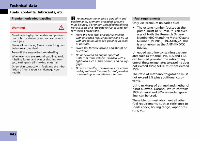
Technical data
Fuels, coolants, lubricants, etc.
! To maintain the engine’s durability and performance, premium unleaded gasoline must be used. If premium unleaded gasoline is not available and low octane fuel is used, fol-low these precautions:
� Have the fuel tank only partially filled with unleaded regular gasoline and fill up with premium unleaded gasoline as soon as possible.
� Avoid full throttle driving and abrupt ac-celeration.
� Do not exceed an engine speed of 3000 rpm if the vehicle is loaded with a light load such as two persons and no lug-gage.
� Do not exceed 2/3 of maximum accelerator pedal position if the vehicle is fully loaded or operating in mountainous terrain.
Only use premium unleaded fuel
� The octane number (posted at the pump) must be 91 min. It is an aver-age of both the Research Octane Number (RON) and the Motor Octane Number (MON): (RON+MON)/2. This is also known as the ANTI-KNOCK INDEX.
Unleaded gasoline containing oxygen-ates such as ethanol, IPA, IBA and TBA can be used provided the ratio of any one of these oxygenates to gasoline does not exceed 10%; MTBE must not exceed 15%.
The ratio of methanol to gasoline must not exceed 3% plus additional cosol-vents.
Using mixtures of ethanol and methanol is not allowed. Gasohol, which contains 10% ethanol and 90% unleaded gaso-line, can be used.
These blends must also meet all other fuel requirements, such as resistance to spark knock, boiling range, vapor pres-sure, etc.
Premium unleaded gasoline
Warning! G
Gasoline is highly flammable and poison-ous. It burns violently and can cause seri-ous injury.
Never allow sparks, flame or smoking ma-terials near gasoline!
Turn off the engine before refueling.
Whenever you are around gasoline, avoid inhaling fumes and skin or clothing con-tact, extinguish all smoking materials.
Direct skin contact with fuels and the inha-lation of fuel vapors can damage your health.
Fuel requirements
442

Technical data
Fuels, coolants, lubricants, etc.
A major concern among engine manu-facturers is carbon build-up caused by gasoline. We recommend only the use of quality gasoline containing additives that prevent the build-up of carbon de-posits.
After an extended period of using fuels without such additives, carbon deposits can build up especially on the intake valves and in the combustion area, lead-ing to engine performance problems such as:
� Warm-up hesitation
� Unstable idle
� Knocking/pinging
� Misfire
� Power loss
In areas where carbon deposits may be encountered due to lack of availability of gasolines which contain these additives, we recommend only the use of additives approved by us for use on Maybach vehi-cles. Refer to Factory Approved Service Products pamphlet (USA only) or contact an authorized Maybach Studio for a list-ing of approved product(s). Follow direc-tions on product label.
Do not blend other fuel additives with fuel. This only results in unnecessary cost and may be harmful to the engine oper-ation.
! Damage or malfunction resulting from poor fuel quality or from blending additional fuel additives other than those tested and ap-proved by us for use on Maybach vehicles are not covered by the Maybach Limited Warranty.
For a listing of approved products, refer to the Factory Approved Service Products pamphlet (USA only) or contact an authorized Maybach Studio.
The engine coolant is a mixture of water and anticorrosion/antifreeze, which pro-vides:
� Corrosion protection
� Freeze protection
� Boiling protection (by increasing the boiling point)
The cooling system was filled at the fac-tory with a coolant providing freeze pro-tection to approximately -35°F (-37°C) and corrosion protection.
! Add premixed coolant solution only. Adding water and MB 325.0 Anticorrosion/Antifreeze separately from each other, could cause engine damage not covered by the Maybach Limited Warranty.
If the antifreeze mixture is effective to-35°F (-37°C), the boiling point of the coolant in the pressurized cooling system is reached at approximately 266°F (130°C).
The coolant solution must be used year round to provide the necessary corrosion protection and increase in the boil-over protection. Refer to Maintenance Book-let for replacement interval.
Gasoline additives Coolants
443

Technical data
Fuels, coolants, lubricants, etc.
Coolant system design and coolant used determine the replacement interval. The replacement interval published in the Maintenance Booklet is only applicable if MB 325.0 Anticorrosion/Antifreeze solution or other products approved by us for use on Maybach vehicles of equal specification are used to renew the cool-ant concentration or bring it back up to the proper level.For information on other products approved by us for use on Maybach vehicles of equal specification, refer to the Factory Approved Service Products pamphlet (USA only) or contact an authorized Maybach Studio.
To provide important corrosion protec-tion, the solution must be at least 50% anticorrosion/antifreeze (equivalent to freeze protection to approximately -35°F [-37°C]). If you use a solution that is more than 55% anticorrosion/antifreeze (freeze protection to approximately –49°F [–45°C]), the engine temperature will increase due to the lower heat trans-fer capability of the solution. Therefore, do not use more than this amount of an-ticorrosion/antifreeze.
If the coolant level is low, water and MB 325.0 Anticorrosion/Antifreeze should be used to bring it up to the prop-er level (have cooling system checked for signs of leakage). Please make sure the mixture is in accordance with label in-structions.
The water in the cooling system must meet minimum requirements, which are usually satisfied by normal drinking wa-ter. If you are not sure about the water quality, consult an authorized Maybach Studio.
444

Technical data
Fuels, coolants, lubricants, etc.
Anticorrosion/antifreeze
Your vehicle contains a number of alumi-num parts. The use of aluminum compo-nents in motor vehicle engines necessitates that anticorrosion/anti-freeze coolant used in such engines be specifically formulated to protect the aluminum parts. Failure to use such
anticorrosion/antifreeze coolant will re-sult in a significantly shortened service life.
Therefore, the following product is strongly recommended for use in your vehicle: MB 325.0 Anticorrosion/Antifreeze agent.
Before the start of the winter season (or once a year in hot southern regions), you should have the anticorrosion/antifreeze concentration checked. The coolant is also regularly checked each time you bring your vehicle to an authorized Maybach Studio for service.
The anticorrosion/antifreeze quantities listed in the table below are in relation to total filling capacity.
Anticorrosion/antifreeze quantity
Approx. freeze protection
-35°F (-37°C) -49°F (-45°C)
All models (main cooling system) 9.0 US qt (8.5 l) 9.9 US qt (9.4 l)
Maybach 57, Maybach 62 (low temperature cooling system) 1.16 US qt (1.1 l) 1.27 US qt (1.2 l)
Maybach 57 S, Maybach 62 S (low temperature cooling system)
1.27 US qt (1.2 l) 1.37 US qt (1.3 l)
445
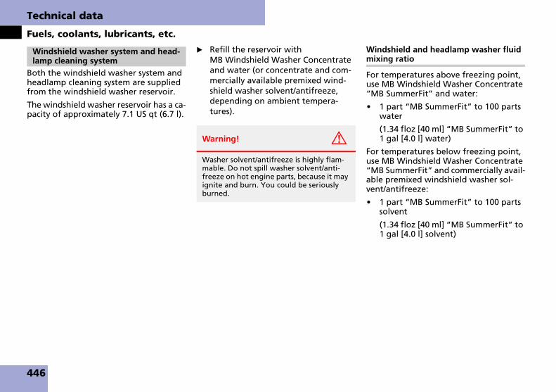
Technical data
Fuels, coolants, lubricants, etc.
Both the windshield washer system and headlamp cleaning system are supplied from the windshield washer reservoir.
The windshield washer reservoir has a ca-pacity of approximately 7.1 US qt (6.7 l).
� Refill the reservoir with MB Windshield Washer Concentrate and water (or concentrate and com-mercially available premixed wind-shield washer solvent/antifreeze, depending on ambient tempera-tures).
Windshield and headlamp washer fluid mixing ratio
For temperatures above freezing point, use MB Windshield Washer Concentrate “MB SummerFit” and water:
� 1 part “MB SummerFit” to 100 parts water
(1.34 floz [40 ml] “MB SummerFit” to 1 gal [4.0 l] water)
For temperatures below freezing point, use MB Windshield Washer Concentrate “MB SummerFit” and commercially avail-able premixed windshield washer sol-vent/antifreeze:
� 1 part “MB SummerFit” to 100 parts solvent
(1.34 floz [40 ml] “MB SummerFit” to 1 gal [4.0 l] solvent)
Windshield washer system and head-lamp cleaning system
Warning! G
Washer solvent/antifreeze is highly flam-mable. Do not spill washer solvent/anti-freeze on hot engine parts, because it may ignite and burn. You could be seriously burned.
446
Index
AABS
Indicator lamp 23, 103, 356Messages in display 365
ABS/ESP®
Warning lamp 354Accelerator position, automatic transmission 181Accessory weight 333Accident 76Active Bi-Xenon headlamps see Head-lampsAdaptive Damping System see ADSAdditional turn signals 407ADS 233Air cleaner see Air filterAir conditioning refrigerant 441Air conditioning system see Automatic climate controlAir conditioning, Cooling 200, 208Air distribution 195, 207Air filter
Message in display 366Air pressure 333Air recirculation mode 196Air vents 192, 201, 203Air volume 195, 207
Airbags 83Children 84Front, Driver 86Front, Passenger 86PASSENGER AIRBAG OFF indicator lamp 362Safety guidelines 85Side impact 87Window curtain 87
Airmatic DC 233Messages in display 376Setting vehicle level 234Suspension tuning 233
Alarm system see Anti-theft alarm sys-temAlignment bolt (vehicle tool kit) 400, 415Anticorrosion/antifreeze 440, 443, 445Antiglare, Rear view mirrors 186Antilock Brake System see ABSAnti-theft alarm systems 110
Immobilizer 110Indicator lamp 110Tow-away alarm 111
Aquaplaning see HydroplaningArmrest 255Ashtrays 260Aspect ratio 333Audio menu 162Auto-dimming, Rear view mirrors 186Automatic central locking 129
Activating/deactivating, Control system 176
Automatic climate control 191Air conditioning refrigerant 441Air conditioning, Cooling 200, 208Air distribution 195, 207Air recirculation mode 196Air vents 192, 201, 203Air volume 195, 207Charcoal filter 198Control panel, Front 193Control panel, Rear 206Front defroster 195Maximum cooling MAXCOOL 196Overview of front passenger compartment 192Overview of rear passenger compart-ment
Maybach 57 202Maybach 62 204
Rear window defroster 190Residual engine heat and ventilation 200Setting the temperature 195, 207
Automatic headlamp mode 143Automatic lighting control, Interior lighting 148Automatic locking when driving 129Automatic shift program 183
447

Index
Automatic transmission 178Accelerator position 181Automatic shift program 183Emergency operation (Limp-Home Mode) 185Gear ranges 182Gear selector lever 178Gear selector lever position 70, 179Gear selector lever positions 180Gear shifting malfunctions 185Kickdown 181One-touch gearshifting 184Program mode selector switch 26, 27, 183Shifting procedure 179Transmission fluid level 310Warning sounds (vehicles with KEYLESS-GO**) 79
AUX sockets 255, 256
BBackrest
Multicontour seats 136Power seats 63, 132, 133, 135
Backrest supportsLumbar region 137Shoulder region 137
Backup lampsReplacing bulbs 407
Bar 333BAS 104
Batteries, SmartKeyChecking battery condition 116Replacing 405
Batteries, SmartKey with KEYLESS-GO**Checking battery condition 121Replacing 405
Batteries, vehicle 417Charge socket (Battery for electrical consumers) 267Charging 420Disconnecting 419For electrical consumers 417For starter 417Jump starting 421Reconnecting 420Reinstalling 420Removing 419
Bead 333Beverage holder see Cup holderBi-Xenon see HeadlampsBottle holder 259Brake Assist System see BASBrake fluid 441
Brake warning lamp 360Checking 306Message in display 381
Brake lampHigh mounted 407Messages in display 393Replacing bulbs 407
Brake padsMessage in display 382
Brake warning lamp 23, 360
Brakes 298Warning lamp 360
Break-in the vehicle 296Bulbs, replacing see Replacing bulbs
CCalifornia retail buyers and lessees, im-portant notice for 11Can holder see Cup holderCapacities and recommended fuel/lubricants 440Cargo area see TrunkCargo tie-down hooks 247Carpet, Cleaning and care of 349Catalytic converter 303CD changer
Compartment for 255, 256Central locking
Automatic 176Locking/unlocking from inside 129
Central locking/unlocking switches 129, 130Certification label 432Champagne flute holder 259
Setting down champagne flutes 260Charcoal filter 198
448

Index
Children in the vehicle 95Airbags 84Blocking of rear window operation 100Infant and child restraint systems 96LATCH-type child seat anchors 99Override switch 100Tether attachment points 98
Cigarette lighter 262Clock 156
In the rear 31, 33, 35, 37Instrument cluster 23See separate operating instructions
Cloth upholstery, Cleaning and care of 349COMAND see separate operating in-structionsCombination switch 74, 145Control system 157Control system menus
Audio menu 162Distronic** menu 167Navigation menu 166Settings 170Standard display 162Telephone 164Trip computer 167Vehicle status message memory 169
Control system submenusConvenience 177Instrument cluster 172Lighting 172Vehicle
Convenience submenuSetting automatic locking 176
Coolant 310, 443Adding 311Anticorrosion/antifreeze mixing ratio and quantity 445Capacities 440, 445Checking coolant level 310Messages in display 383, 384Temperature 304Temperature gauge 23, 155Warning lamp 384
Cornering lampMessages in display 392Replacing bulbs 407, 409
Courtesy lighting 153Cruise control 221Cruise control lever 227Cup holder 25, 258
RearCleaning 349
Curb weight 333Curtains
Partition curtain* 273Rear side windows* 269Rear window 267
DDaytime running lamp mode 144
Setting 173Deep water see Standing waterDefrosting, Rear 190
Delayed switch-offExterior lamps 174Interior lighting 175
Department of Transportation see DOTDifficulties
While driving 76While starting 71
Digital clock see ClockDigital speedometer 162Dimensions, Vehicle 439Direction of rotation, Tires 315Displays
Digital speedometer 162Maintenance service indicator 339Messages in display 365Multifunction display 157Outside temperature 23, 155Showing malfunctions 169Symbol messages 376Text messages 365Vehicle status messages 364Vehicle system settings, Control system 170
Distance to empty (Range), Trip computer 168
449

Index
Distronic** 223Activating 227Cleaning system sensor 346Deactivating 229Distance warning function** 230Driving hints 231Menu 167, 226Messages in display 366Sensor cover 346Warning and indicator lamps 225Warning sounds 225
DoorClosing the rear doors automatically from the inside (Maybach 62) 123Entry lamps 153Inside door handle 122Inside door handle, Front 29Inside door handle, Rear (Maybach 57) 54Inside door handle, Rear (Maybach 62) 55Locking, SmartKey 80Locking, SmartKey with KEYLESS-GO** 80Message in display 388Opening from inside 122Power closing assist for doors 128Remote door unlock (Tele Aid) 288Unlocking the driver’s door, Mechani-cal key 401Unlocking, SmartKey 58
Door control panelIn the rear
Maybach 57 54Maybach 62 55
Door handleLock button (KEYLESS-GO**) 80
DOT 333Drink holder see Cup holderDrinking and driving 297Driving 68
Abroad 303Hydroplaning 300In winter 301Instructions 297Problems 76Safety systems 103Systems 221Through standing waterWith Distronic** 231
Driving safety systemsABS 103BAS 104Electro-hydraulic brake system 107ESP® 105
Driving systemsAirmatic DC 233Cruise control 221Distronic** 223Parktronic 237Vehicle level control 234
Driving tips 181Accelerator position 181Kickdown 181
DVD playerCompartment for 39, 41, 45, 255, 256Storage compartment for 43
EEasy-entry/exit feature 65, 177Electrical fuses see FusesElectrical outlets see Power outletsElectrical system, Technical data 438Electro-hydraulic brake system
Messages in display 378, 379, 381Self-check 108Warning lamp 107
Electronic Stability Program see ESP®
Electrotransparent roof lighting* 152Electrotransparent roof* 218
Cleaning 350Lowering panel 350Making opaque/transparent 219, 220Opening/closing screen 219, 220Operating from the cockpit 218Operating from the rear 219Operating the screen 28, 218
Emergency callsTele Aid calls 283
Emergency operation (Limp-Home Mode) 185
450

Index
Emergency operationsLocking/unlocking the vehicle 401Power tilt/sliding sunroof, Manual operation 403Remote door unlock 288Trunk, Releasing from inside 127Trunk, unlocking 402
Emergency, In case ofBattery, Jump starting 421First aid kit 400Flat tire, Changing 413Fuses 426Hazard warning flasher 147Instrument cluster, Indicator lamps 354Roadside Assistance 12Roadside Assistance (Tele Aid) 285Towing the vehicle 423
Emission control 304Emission control information label 433Emission control system warranties 10
EngineBelt layout 434Cleaning 344Compartment 307Malfunction indicator lamp 23, 361Number 435Oils 441Starting with KEYLESS-GO** 60Starting with SmartKey 60Tachometer 23Technical data 435Turning off with KEYLESS-GO** 79Turning off with SmartKey 78
Engine coolant see CoolantEngine oil 309, 441
Adding 310Additives 441Changing 441Checking level 309Consumption 309Display messages 388Filler neck 310Messages in display 309, 388Recommended engine oils and oil filters 441
Engine oil level see Oil levelESP® 105
Messages in display 354Warning lamp 23, 105, 354
ETD 95Safety guidelines 85
Exterior rear view mirrors 67, 186, 188Parking position 141, 187
External communication (special order equipment) 276
FFiller neck, Engine oil 310First aid kit 400Flat tire 324, 413
Jacking up the vehicle 414Lowering the vehicle 416Mounting the spare wheel 413Preparing the vehicle 413
Flexible Service System see FSSFluids
Automatic transmission fluid 310Brake fluid 441Capacities 440Engine coolant 310, 440Engine oil 309, 440, 441Power steering fluid 440Windshield washer and headlamp cleaning system 441, 446
Fog lamps 145, 407Messages in display 391Replacing bulbs 407
Folding table* 39, 43, 263Front airbags 86Front lamps see headlampsFront passenger front airbag 86Front seat head restraints see Head re-straintsFSS (Canada vehicles) 339
451

Index
Fuel 306Additives 443Capacity, Fuel tank 440Filling the tank 305Fuel filler flap and cap 305Fuel reserve warning lamp 23, 355Premium unleaded gasoline 306Requirements, Octane rating 442
Fuel filler flap 305Locking 305Unlocking 305
Fuel reserve warning lamp 23, 355Fuel tank
Capacity 440Filler flap 305
Fuels, coolants, lubricants, etc.Capacities 440
Fuse box 428Fuses 426
Aids for replacing fuses 426Fuse box in engine compartment 427Fuse box in passenger compartment 427Fuse box in trunk 428Fuse chart 400Fuse extractor 400Replacing 426Spare fuses 400
GGarage door opener 28, 289Gasoline see FuelGAWR 334
Gear rangeAutomatic transmission 182Limiting 182Shifting into optimal 184
Gear selector lever 70, 178Cleaning 348Gearshift pattern 178Lock 70Message in display 373Position 179, 180Position indicator 180Shifting procedure 179
Glove box 201, 249Good visibility 186GPS 282Gross Axle Weight Rating see GAWRGross Vehicle Weight Rating see GVWRGross Vehicle Weight see GVWGVW 334GVWR 334
HHands-free microphone 28Hard plastic trim items, Cleaning 348Hazard warning flasher 147Head restraints
Adjusting 132, 133Front seat 64Rear seats 131
Headlamp cleaning system 21, 186, 306, 311Headlamp switch-off delay see Delayed switch-off, Exterior lamps
Headlamps 143Active Bi-Xenon headlamps 142Automatic headlamp mode 143Bi-Xenon 142, 407Cleaning lenses 345Cleaning system 186, 311, 446High beam see High beam flasherHigh beam see High beam headlampsMessages in display 390, 391, 392, 393, 394Replacing bulbs 408Switch 73
Headliner and shelf below rear window, Cleaning and care of 349Headliner lamps and pillar uplights* 152
Lighting 48, 49Headphone jacks 39, 41, 43, 45, 255, 256Headphones
Storage compartmentsIn rear doors 251
Heated seats 138Heated steering wheel 276
Lever 21Height adjustments
Vehicle level 234High beam flasher 145, 146High beam headlamps
Indicator lamp 23Messages in display 391Switching 74Switching on 146
452

Index
High mounted brake lamp 407Hood 307
Message in display 388Opening 307
Horn 21HVAC see Automatic climate controlHydroplaning 300
IIdentification labels 432Identification Number, Vehicle (VIN) 432, 433Ignition 60, 71Immobilizer 110Indicator lamps see Lamps, indicator and warningInfant and child restraint systems see Children in the vehicleInflation pressure see TiresInfrared reflecting windshield 293Inside door handle 122Instrument cluster 22, 154
Cleaning 348Illumination brightness 154Lamps 354Messages in display see Multifunction display
Instrument lighting see Instrument clus-ter, Illumination brightnessInstrument panel see Instrument cluster
Interior lightingDelayed switch-off 175Front 148Rear 149
Interior rear view mirror 67Auto-dimming 186
Interior storage spaces see Storage com-partments
JJack 400, 415Jacking up the vehicle 414Jump starting 421
KKey, Mechanical 401Key, SmartKey 58, 114
Battery check lamp 114, 121Checking batteries 121Factory setting 115Global locking 116Global unlocking 115, 116Locking/unlocking 58, 80, 114Loss of 121Messages in display 390Opening and closing the power tilt/sliding sunroof 211
Opening and closing the power windows 211Opening the trunk 124Positions in starter switch 60Remote control 114Replacing the batteries 405Restoring to factory setting 116Selective setting 116Starting the engine 71Turning off the engine 78
Key, SmartKey with KEYLESS-GO** 117
Battery check lamp 117Checking batteries 121Factory setting 120Global locking 120Global unlocking 120Locking/unlocking 59, 80, 117Loss of 121Messages in display 389Opening and closing the power tilt/sliding sunroof 211Opening and closing the power windows 211Opening the trunk 124Remote control 117Replacing the batteries 405Restoring to factory setting 121Selective setting 120Starting the engine 60Turning off the engine 79
Kickdown 181Kilopascal 334
453
Index
LLabels 432, 433
Certification 432Emission control information 433Vacuum line routing diagram label 433
Lamp sensorMessage in display 390
Lamps, exteriorMessage in display 390Rear 407
Lamps, indicator and warningABS 23, 356Anti-theft alarm systems 110
Battery (SmartKey with KEYLESS-GO**) 121Battery (SmartKey) 121Brakes 23, 360CHECK ENGINE 361Coolant 383Distronic** 23, 225, 356Electro-hydraulic brake system 107Engine diagnostics 361Engine malfunction 23, 361ESP® 23, 105, 354Fuel reserve 355High beam headlamp 23Instrument cluster 354–355Parktronic 238PASSENGER AIRBAG OFF 25, 362Restraint system 23Seat belt telltale 23Seat belts 357, 358SRS 83Tire inflation pressure 23, 359, 396Tow away alarm 110Turn signals 23
Language, Setting 172LATCH-type child seat anchors see Chil-dren in the vehicleLeather upholstery, Cleaning and care of 349Level control
Airmatic DC 236Level control system
Airmatic DC 233
License plate lampMessages in display 393Replacing bulbs 407, 410
Light alloy wheels, Cleaning 348Light sensor 390Lighter see Cigarette lighterLighting, Exterior and interior 142Limp-Home Mode 185Loading see Vehicle loadingLocator lighting 145Lock button
Door handle 80SmartKey 114SmartKey with KEYLESS-GO** 117Trunk 121
Locking knob 122Loss of
Service and Warranty Information Booklet 431SmartKey 121SmartKey with KEYLESS-GO** 121
Low beam headlamps 142Messages in display 391Replacing bulbs 407Switching on 73
LoweringVehicle 416
Lubricants 440
454

Index
MMaintenance 11, 339
Calling up service indicator display 340Clearing service indicator message 340FSS (Canada vehicles) 339Maintenance System (U.S. vehicles) 339Resetting service indicator 341Service indicator 339Service term exceeded 340
Maintenance System (U.S. vehicles) 339Manual headlamp mode see HeadlampsMassage function (PULSE, Multicontour seats) 137Maximum load rating, Tires 334Maximum loaded vehicle weight 334Maximum tire inflation pressure 334Maybach battery charger* 267Maybach 62 with partition*
Storage pocket 37, 254Maybach 62 without partition*
Storage pocket 254Mechanical key 401
Loss of 121Memory function 140Menus see Control system menusMessages in display see Multifunction display messages
MicrophoneExternal communication 276Hands-free 28
Mirrors 66Adjusting 66Auto-dimming 186Exterior rear view mirror parking position 187Exterior rear view mirrors 67Interior rear view mirror 67
Mobile phone see TelephoneMON 306MP3-CD operation
Selecting tracks 164Multicontour seats 137Multifunction display 23, 24, 157, 158, 162
Selecting language 172Standard display 161, 162
Multifunction display messages 365ABS 365Air filter 366Airmatic DC 376Battery 366, 377Brake fluid 381Brake lamps 393Brake pads 382Check engine 361Coolant 384Coolant level 383Cruise control 386Distronic** 366Doors 388Electro-hydraulic brake system 378, 379, 381Engine oil 309, 387, 388Engine oil level 388ESP® 368Fog lamps 391, 393Fuel cap 395Gear selector lever 373Headlamps 390, 391, 392, 393, 394Hood 388Parking brake 377SmartKey 390SmartKey with KEYLESS-GO** 389Steering oil 395Tele Aid 373Tires 375, 396–399Trunk 388Washer fluid 395
455

Index
Multifunction steering wheel 21, 24, 158
Button operation 158
NNavigation system
Operating 166See separate COMAND operating in-structions
Navigation system DVD drive 256Neutral gear position 70Neutral gear position, Automatic transmission 178, 180New vehicle break-in 296Night security illumination 145, 174Non-smokers equipment* 263Normal occupant weight 334Number, vehicle identification (VIN) 432, 433
OOccupant distribution 334Occupant safety 82
Airbags 83Children and airbags 84Children in the vehicle 95Fastening the seat belts 68Infant and child restraint systems 98LATCH-type child seat anchors 99Seat belts 68, 92
Odometer 23, 157Oil see Engine oil
One-touch gearshiftingAutomatic transmission 184Gear selector lever 184
Operating safety 15Ornamental moldings, Cleaning 345Outside microphone 276Outside temperature indicator 23, 31, 33, 35, 37, 155Overdue maintenance service 340Overhead control panel 28
PPaintwork, Cleaning 343Panic alarm 102Panic button 102Parking 77, 299Parking Assist System (PAS) 240
Camera 241, 347Cleaning of the camera lens 347Parallel parking 244Parallel parking button 26, 27Reverse parking (back-in parking) 243Switching on 242
Parking brake 77Message in display 377
Parking lampsMessages in display 392, 394Replacing bulbs 407, 409
Parking positionExterior rear view mirrors 141, 187Gear position 70
Parktronic 237Activating/deactivating 240Cleaning system sensors 346Malfunctioning 240Minimum distance 238Range of the sensors 238Sensors 238Warning indicator 21, 39, 41, 43, 45, 238, 239Warning sound 240
Partition* 271Opening/Closing 273
Parts service 430PASSENGER AIRBAG OFF
Indicator lamp 25, 362Passenger compartment 302
Fuse box 427Interior rear view mirror 67
Passenger safety see Occupant safetyPassenger seat
Adjusting from the rear 54Pedals 297Plastic and rubber parts, Cleaning 348Poly-V-belt drive 434
Layout 434Power assistance 297Power closing assist for doors and trunk lid 128Power folding exterior rear view mirrors 188Power outlets 266Power tilt/sliding sunroof 212
456

Index
Power tilt/sliding sunroof (Maybach 57)Opening/closing 212Opening/closing in an emergency 403Stopping 213Synchronizing 213
Power tilt/sliding sunroof (Maybach 62)Opening/closing 214, 215Opening/closing in an emergency 404Operating from cockpit 215Operating from the rear passenger compartment 216Stopping 215, 217Synchronizing 217
Power washer 343Power windows 209
Cleaning 347Operating 209Rear door window, Blocking operation 100Synchronizing 210
Practical hints 354Premium unleaded gasoline 442Problems
While driving 76With vehicle 16
Product information 9Production options weight 334Program mode see Automatic transmis-sion, Automatic shift programProgram mode selector switch
Automatic shift program 183
PSI 334PULSE function (Massage function) 137Push-start see Tow-start
RRadial-ply tires
Summer tires 437Radio
Selecting stations 163Selecting stations, Satellite radio (USA only) 163Station selection setting, Control system 176
Radio transmitters 303Range (distance to empty) 168Reading lamps
Front 148Rear 149
Rear bench seatMaybach 57 with rear center seat* 40Maybach 62 with rear center seat* 44
Rear center console 46Maybach 57 46, 47Maybach 62 with electrotransparent roof* 51, 52Maybach 62 with power tilt/sliding sunroof 48, 49
Rear door windowsBlocking operation 100
Rear fog lamp see Fog lampsRear lamps see Tail lamps
Rear passenger compartmentControl panel
Maybach 57 30, 32Maybach 62 34Maybach 62 with partition* 36Maybach 62 without partition* 34
Rear seat head restraints see Head re-straintsRear seats 131
AdjustingHead restraint tilt 131
Adjustment 131Extending and retracting rear seat head restraints 134
Rear view mirrors see MirrorsRear window curtain 267Rear window defroster 190Recommended tire inflation pressure 334Recovery services, Stolen vehicle (Tele Aid) 288Refrigerant, Air conditioning 441Refrigerator** 265
Cleaning 343Controlling temperature 265Opening 265Rear center armrest 255Switching on/off 265
Refueling 305Regular checks 306Remote control
SmartKey 114SmartKey with KEYLESS-GO** 117
457

Index
Remote door unlock 288Remote rear door closing 123Remote trunk opening/closing switch 124, 125Replacing bulbs 406
Additional turn signals 408Backup bulbs 408Brake lamp 408Cornering lamp 409Fog lamps 408Front turn signal bulb 410High beam flasher bulb 409High mounted brake lamp 408License plate lamp 410Parking lamps 409Side marker bulb 410Standing lamps 409Turn signal lamps 407
Reporting safety defects 17Reset button, In instrument cluster 154, 170Residual engine heat and ventilation 200Restraint system
See Children in the vehicleReverse gear position 70, 73Reverse gear position, Automatic transmission 178, 180Rims 334, 437Rims (light alloy) 437Roadside Assistance 12, 285RON 306Rubber parts, Cleaning 348
SSafety
Driving safety systems 103Occupant 82Reporting defects 17
Safety belts see Seat beltsSatellite radio (USA only) 163Seat belts 92
Children in the vehicle 95Cleaning 349Fastening 68Force limiter 95Proper use of 69, 93Safety guidelines 85Telltale 23, 357, 358Warning sounds 92
Seating capacity 316Seats 62
Adjustment 63Adjustment, Rear seat (Maybach 57) 132Adjustment, Rear seat (Maybach 62) 133Heating 138Memory function 141Multicontour 136Setting from rear 135Ventilation* 139
Securing cargo 247Selector lever see Gear selector leverSelf-test
Tele Aid 282Service and warranty information 10
Service intervals see Maintenance, Ser-vice indicatorService life, Tires 314Service see MaintenanceService system see FSS (Canada vehicles) or Maintenance System (U.S. vehicles)Service, Parts 430Settings
Control system menus 161Control system submenus 161Factory, SmartKey 115Factory, SmartKey with KEYLESS-GO** 120Individual, SmartKey 116Individual, SmartKey with KEYLESS-GO** 120Individual, Vehicle 170Resetting all, Control system 170Selective, SmartKey 116Selective, SmartKey with KEYLESS-GO** 120
Shelf below rear window, Cleaning and care of 349Shift program mode, Automatic transmission 183Shifting, Automatic transmission 178Side impact airbags 87Side marker lamps 407
Cleaning lenses 345Messages in display 392Replacing bulbs 407, 410
Side windows see Power windowsSidewall 334
458

Index
SmartKey see Key, SmartKeySmartKey with KEYLESS-GO** see Key, SmartKey with KEYLESS-GO**Snow chains 338Snow tires 338Solar panel* 208Spare fuses 400Spare wheel 437
Mounting 413Speed settings
Cruise control 222Distronic** 228
Speedometer 23, 225In the rear 31, 33, 35, 37
SRS 82Indicator lamp 23, 359Message in display 373
Standing lampsReplacing bulbs 407
Standing water, Driving through 302Starter battery 417Starter switch 21
Positions 60Starting difficulties, Engine 71Starting, Engine 70Steering column 65Steering gear oil
Message in display 395Steering wheel 64
Adjusting 64Buttons 158Cleaning 348Heated 276
Stolen Vehicle Recovery services 288Stopping
Power tilt/sliding sunroof (Maybach 57) 213Power tilt/sliding sunroof (Maybach 62) 215Windows 210
Storage compartment/drawerBetween the front seats (Maybach 62 with partition*) 252
Storage compartments 248Armrest, Front 263Between rear seats 255
For wireless surround sound headphones 251
Between the front seats (Maybach 62 with partition*) 252Compartment for the front telephone 250For CD changer 255, 256For DVD player 255, 256Front doors 250Glove box 249Rear center armrest 263Rear center console 252Rear doors, Maybach 57 251Rear doors, Maybach 62 251Refrigerator** 255Telephone 250, 255Under the driver’s seat 251With navigation system DVD drive 256
Storage pocketMaybach 62 with partition* 37, 254Maybach 62 without partition* 254
Storing tires 315Submenus see Control system submenusSummer opening feature 211Sun visors 189Sunroof see Power tilt/sliding sunroofSymbols used in this operator’s manual 14
TTachometer 23, 155
Overspeed range 155Tail lamps
Cleaning lenses 345Messages in display 394Replacing bulbs 407
Tar stains 343
459

Index
Technical dataAir conditioning refrigerant 441Brake fluid 441Capacities fuels, coolants, lubricants, etc. 440Coolant 440, 443Electrical system 438Engine 435Engine oil additives 441Engine oils 440, 441Fuel requirements 440, 442Gasoline additives 443Main dimensions and weights 439Premium unleaded gasoline 440, 442Rims and tires 436Windshield washer and headlamp cleaning system 441Windshield washer system 446
Tele Aid 281Call priority 287Emergency calls 283Hands-free microphone 28Information 287Initiating an emergency call manually 284Messages in display 373Remote door unlock 288Roadside Assistance 285SOS button 284Stolen Vehicle Recovery services 288System self-check 282
Telephone 277Answering/ending a call 166Compartment in the front 250, 278Compartment in the rear 255, 256, 280Hands-free microphone 28In the front 278In the rear 280Operation 277Phone book 165Redialing 166
Telephone cradleChanging 279
TemperatureInterior temperature 207Outside indicator 155
Tether attachment points see Children in the vehicleTie-down hooks, Trunk 247Tightening torque, Wheel bolts 416Tilt/sliding sunroof see Power tilt/sliding sunroofTIN 335Tire and Loading Information Placard 315Tire and loading terminology 333
Tires 313Care and maintenance 313Chains 338Checking tire inflation pressure 321Cleaning 315Direction of rotation 315Driving instructions 300Important notes, Tire inflation pressure 320Inflation pressure 321Inspection 314Load rating 335Messages in display 375, 396–399
460

Index
Ply composition and material used 335Problems under-/overinflation 325Retreads 313Rims and tires 436Rotating 336Service life 314Sizes 436Snow 337Spare wheel 400, 413Speed rating 301, 328, 335, 337Storing 315Temperature 320, 332Terminology 333Tire Identification Number see TINTraction 300Tread 335Tread depth 314, 338Treadwear indicators 335Vehicle maximum load on 335Wear pattern 336Winter 338
Tools 400Top tether
Children in the vehicle 98Tow-away alarm 111Towing eye bolt 400Towing the vehicle 423Tow-start 423Traction 183, 335Transmission see Automatic transmis-sionTraveling abroad 303
Tread 335Tread depth 314Treadwear indicators 335Trip computer 167Trip odometer 155Trunk
Closing 125Emergency release 127Fuse box 428Lighting 153Message in display 388Opening 123, 124Power closing assist for trunk lid 128Tie-down hooks 247Valet locking 127
Trunk lid see TrunkTumbler holder see Cup holderTurn signal lamps
Cleaning lenses 345Messages in display 393Replacing bulbs 410
Turning off engine 78Two-way intercom* 274
Adjusting volume 275Operating 274Switching on/off 274
UUmbrella 257Uniform Tire Quality Grading Standards 335Units, Settings
Speedometer 172
Unleaded gasoline, Premium 306, 440, 442Upholstery, Cleaning and care of 349Useful features 248
VVacuum line routing diagram label 433Valet locking 127Vanity mirror
In the rear 248In the sun visor 248Opening/closing 248
VehicleBatteries 417Breaking-in the vehicle 296Care 342Control system, Settings menu 170Dimensions 439Locking/unlocking 58, 79, 114Locking/unlocking in an emergency 401, 402Lowering 416Modifications and alterations, Operat-ing safety 15Towing 423Washing 344Weights 439
Vehicle jack 400, 415Vehicle level
SettingAutomatic 236
Vehicle level control see Airmatic DCVehicle lighting 142, 306
461

Index
Vehicle loading 247Cargo tie-down hooks 247Instructions 247Load limit 316Terminology 315, 333
Vehicle maximum load on the tire 335Vehicle Recovery services, Stolen (Tele Aid) 288Vehicle status message memory 169Vehicle tool kit 400Vehicle washing 344Voice control system
Hands-free microphone 28Lever 21
WWarning lamps see Lamps, indicator and warningWarning sounds
Distance warning function** 230Distronic** 225Exterior lamps 143Parking brake 73, 360Parktronic 240Seat belt telltale 92Switching off headlamps 80
Warranty coverage 10, 431Washer fluid see Windshield washer flu-idWashing the vehicle 342Wear pattern, Tires 336Weights, Vehicle 439
WheelBolts 416Change 413Removing 415Sizes 326, 437Spare 400, 413Tightening torque 416Tires and wheels 313
Window curtain airbags 87Windows see Power windowsWindshield
Cleaning 75Cleaning wiper blades 347Defogging 195
Windshield washer fluid 311Message in display 395Mixing ratio 446Refilling 311, 446Wiping 75
Windshield wipers 21, 74Cleaning wiper blades 347Replacing wiper blades 411
Winter driving 337Snow chains 338Tires 338
Winter driving instructions 301Winter tires 338Wood trims, Cleaning 350
462

