operator’s and parts manual no. pb-2way-6200 for 6200 series...
TRANSCRIPT

6990633 (1-13) Printed in U.S.A. © Bobcat Company 2013
Over70 yearsof serviceto our customers
TSS VARIABLE SPEED MODELFront & Rear Unload Forage Boxes
with Independent Outfeed Clutch
MEYER
MANUFACTURED BY
574 West Center AvenueP.O. Box 405
Dorchester, Wisconsin 54425-0405Phone 715-654-5132 • FAX 715-654-5513
1-800-325-9103www.meyermfg.com
E-mail: [email protected]
Meyer Mfg. Corp.
DO NOT OPERATE EQUIPMENT UNTIL THIS MANUAL HAS BEEN READ AND UNDERSTOOD.
6200 SERIES:Model 6220Model 6222Model 6224
OPERATOR’S AND PARTS MANUAL NO. PB-2WAY-6200 FOR
6200 SERIES
1 / 2015

INTRODUCTION
Congratulations on your purchase of a new Meyerfarm equipment product. Undoubtedly you have givenmuch consideration to your purchase and we’re proudthat you have selected Meyer. Pride in craftsmanship,engineering and customer service have made Meyerproducts the finest in the farm equipment industrytoday.
There is no substitute for quality. That is whythousands of people like you have purchased Meyerfarm equipment. They felt it was the best equipment toserve their farming needs, now and in years to come.We ask that you follow our policy of “safety first,” andwe strongly suggest that you read through the owner’smanual before operating your Meyer farm equipment.
Meyer Manufacturing Corporation wants to thank youfor not compromising quality. We are determined tooffer excellence in customer service as well asprovide you with the very best value for your dollar.
REMEMBER:
FARM EQUIPMENT BUYERSTRUST THE NAME MEYER!
Sincerely,
All Employees ofMEYER MANUFACTURING CORPORATION
Meyer Mfg. Corp. reserves the right to makeimprovements in design, or changes in specificationsat any time, without incurring any obligation to ownersof units previously sold.
This supersedes all previous published instructions.
IMPORTANT:At the front of this manual is an “Owner's RegistrationForm”. Be sure your dealer has completed this formand promptly forwarded a copy to MeyerManufacturing to validate the manufacturer’s warranty.The product model and serial number are recorded onthis form and below for proper identification of yourMeyer Forage Box by your dealer and themanufacturer when ordering repair parts. The serialnumber plate is found near the control levers on yourforage box and stamped in the front corner of the lefthand end frame.
At the back of this manual is the repair parts section.All replacement parts are to be obtained from orordered through your Meyer dealership. Whenordering repair parts, refer to the parts section andgive complete information including quantity, correctpart number, detailed description and even Model No.and Serial No. of the forage box which needs repairparts.
HOW TO READ YOUR SERIAL NUMBER
Your serial number is stamped above the dischargeopening on the unit discharge end frame.
Example: 11T2242
NOTE: All references to right hand (RH), left hand(LH), front and rear apply to the product as viewedfrom the rear of the box.
IMPORTANT: The standard forage box header unitdischarges to the LH side and the parts illustrationsdepict these units. If you have an optional RH unit,always specify the part number shown in this bookfollowed by -RH. Nearly all header parts appearsimilar to the standard unit but are really mirrorimages. Box parts are all identical. If you specify -RH and there is no difference in the item you wishto order, this will be properly interpreted at thefactory and will not cause any problem.
Model No.
Serial No.
Date of Purchase
Model Year / TSS / Model / Sequence of Build
11 T 2 242
6200 Series - 2 -
PRE-DELIVERY & DELIVERY CHECK LIST
This Pre-Delivery & Delivery Check List must be gone through by the Selling Party and the Customer tovalidate the Owner’s Registration Form.
Meyer Manufacturing Corporation
Phone: 715-654-5132 • Toll-Free: 1-800-325-9103 • P.O. Box 405 • Dorchester, WI 54425
TSS Check List
All shields and guards are in place and securelyfastened.
All bolts and other fasteners are secure and tight.
All mechanisms operate trouble free.
All grease fittings have been lubricated, gearboxes filled to proper levels, and all roller chainsare oiled. See “Lubrication” section of thismanual.
PTO shields turn freely.
Cross Conveyor Chain and Main Apron Chainsare at proper tension. See “Adjustments” sectionin this manual.
All roller chain springs adjusted properly forautomatic tensioning. See “Adjustments” sectionin this manual.
Emergency Stop and Trip Cablesoperateproperly.
All decals are in place and legible.
PRE-DELIVERY CHECK LIST
After the New Meyer Forage Box has been completelyset-up, check to be certain it is in correct running orderbefore delivering it to the customer.
The following is a list of points to inspect:
Check off each item as you have made the properadjustments and found the item operatingsatisfactorily. Any adjustments made, MUST beaccording to specifications defined in this manual.
DELIVERY CHECK LIST
The following check list is an important reminder ofvaluable information that MUST be passed on to thecustomer at the time the unit is delivered.
Check off each item as you explain it to thecustomer.
Explain to the customer that pre-delivery checklist was fully completed.
Give customer the Owner & Operator’s Manual.Instruct to read and completely understand itscontents BEFORE attempting to operate theForage Box.
Explain and review with customer the New MeyerForage Box manufacturer’s warranty.
Show the customer where to find the serialnumber on the implement.
Explain and review with the customer “SafetyPrecautions” section of this manual.
Explain and review with customer the proper“Start-up and Operating Procedures” sections ofthis manual.
Demonstrate the “Emergency Stop” operation,activation and reset. Also, demonstrate the PTOShaft Locking Device, Main Clutch adjustmentsand the three Control Lever operations.
Explain that regular lubrication and properadjustments are required for continued properoperation and long life of the Forage Box. Reviewwith the customer the “Lubrication” and“Adjustments” sections of this manual.
Explain the importance of cross conveyor & mainapron chain, and the need to watch and tightenduring the break in period.
Fully complete this “PRE-DELIVERY &DELIVERY CHECK LIST” with the customer.
6200 Series - 3 -

Meyer Manufacturing Corporation574 West Center Avenue
Dorchester, WI 54425Phone: 1-800-325-9103
Fax: 715-654-5513Email: [email protected]: www.meyermfg.com
6200 Series - 4 -
TABLE OF CONTENTSINTRODUCTION . . . . . . . . . . . . . . . . . . . . . . . . . . . . . . . . . . . . . . . . . . . . . . . . . . . . . . . . . . . . . . . .2
HOW TO READ YOUR SERIAL NUMBER . . . . . . . . . . . . . . . . . . . . . . . . . . . . . . . . . . . .2PRE-DELIVERY & DELIVERY CHECK LIST . . . . . . . . . . . . . . . . . . . . . . . . . . . . . . . . . . . . . . . . . . . 3MANUFACTURER’S WARRANTY . . . . . . . . . . . . . . . . . . . . . . . . . . . . . . . . . . . . . . . . . . . . . . . . . . . 7SAFETY PRECAUTIONS . . . . . . . . . . . . . . . . . . . . . . . . . . . . . . . . . . . . . . . . . . . . . . . . . . . . . . . . . . 9SAFETY FIRST . . . . . . . . . . . . . . . . . . . . . . . . . . . . . . . . . . . . . . . . . . . . . . . . . . . . . . . . . . . . . . . . 10
DECALS - 6200 . . . . . . . . . . . . . . . . . . . . . . . . . . . . . . . . . . . . . . . . . . . . . . . . . . . . . . . . . . . . 12WARNING . . . . . . . . . . . . . . . . . . . . . . . . . . . . . . . . . . . . . . . . . . . . . . . . . . . . . . . . . . . . . . . . . . . . 14
OPERATION OF THE EMERGENCY STOP . . . . . . . . . . . . . . . . . . . . . . . . . . . . . . . . . . . . . . 14EMERGENCY STOP TRIP LOCATIONS . . . . . . . . . . . . . . . . . . . . . . . . . . . . . . . . . . . . . . . . . 14RESETTING THE EMERGENCY STOP . . . . . . . . . . . . . . . . . . . . . . . . . . . . . . . . . . . . . . . . . 14
PRE-OPERATION . . . . . . . . . . . . . . . . . . . . . . . . . . . . . . . . . . . . . . . . . . . . . . . . . . . . . . . . . . . . . . 15TRANSPORTING . . . . . . . . . . . . . . . . . . . . . . . . . . . . . . . . . . . . . . . . . . . . . . . . . . . . . . . . . . . . . . . 15TRUCK MOUNT FORAGE BOXES . . . . . . . . . . . . . . . . . . . . . . . . . . . . . . . . . . . . . . . . . . . . . . . . .17
FRONT UNLOAD DRIVE COUPLER “SET-UP” (PTO OR HYDRAULIC DRIVE) . . . . . . . . . . 17REAR UNLOAD DRIVE COUPLER “SET-UP” (PTO OR HYDRAULIC DRIVE) . . . . . . . . . . . . . . . 19FRONT UNLOAD VARIABLE SPEED OPERATION WITH INDEPENDENT OUTFEED CLUTCH .21
FORAGE BOX CONTROL LEVERS . . . . . . . . . . . . . . . . . . . . . . . . . . . . . . . . . . . . . . . . . . . . 21UNLOADING THE FORAGE BOX . . . . . . . . . . . . . . . . . . . . . . . . . . . . . . . . . . . . . . . . . . . . . .22
START UP PROCEDURES . . . . . . . . . . . . . . . . . . . . . . . . . . . . . . . . . . . . . . . . . . . . . . . 22SHUTDOWN PROCEDURES . . . . . . . . . . . . . . . . . . . . . . . . . . . . . . . . . . . . . . . . . . . . . 23
REAR UNLOAD OPERATION PTO OR HYDRAULIC DRIVE . . . . . . . . . . . . . . . . . . . . . . . . . . . . . 24LUBRICATION . . . . . . . . . . . . . . . . . . . . . . . . . . . . . . . . . . . . . . . . . . . . . . . . . . . . . . . . . . . . . . . . . 26
DAILY LUBRICATION . . . . . . . . . . . . . . . . . . . . . . . . . . . . . . . . . . . . . . . . . . . . . . . . . . . . . . . . 26BEGINNING OF CROP MAINTENANCE . . . . . . . . . . . . . . . . . . . . . . . . . . . . . . . . . . . . . . . . . 26END OF CROP CLEANUP AND MAINTENANCE . . . . . . . . . . . . . . . . . . . . . . . . . . . . . . . . . . 27
TWO-SPEED OPERATION . . . . . . . . . . . . . . . . . . . . . . . . . . . . . . . . . . . . . . . . . . . . . . . . . . . . . . . 28CONTROL LEVER . . . . . . . . . . . . . . . . . . . . . . . . . . . . . . . . . . . . . . . . . . . . . . . . . . . . . . . . . . 28UNLOADING THE FORAGE BOX . . . . . . . . . . . . . . . . . . . . . . . . . . . . . . . . . . . . . . . . . . . . . .28START UP PROCEDURES: . . . . . . . . . . . . . . . . . . . . . . . . . . . . . . . . . . . . . . . . . . . . . . . . . . . 29
TWO SPEED LUBRICATION AND MAINTENANCE . . . . . . . . . . . . . . . . . . . . . . . . . . . . . . . . . . . . 30ROLLER CHAIN DRIVES . . . . . . . . . . . . . . . . . . . . . . . . . . . . . . . . . . . . . . . . . . . . . . . . . . . . 30RANGE CONTROL CLUTCH ENGAGEMENT . . . . . . . . . . . . . . . . . . . . . . . . . . . . . . . . . . . . 30DAILY LUBRICATION MAINTENANCE . . . . . . . . . . . . . . . . . . . . . . . . . . . . . . . . . . . . . . . . . .30BEGINNING OF CROP MAINTENANCE . . . . . . . . . . . . . . . . . . . . . . . . . . . . . . . . . . . . . . . . . 30END OF CROP CLEANUP AND MAINTENANCE . . . . . . . . . . . . . . . . . . . . . . . . . . . . . . . . . . 30
ADJUSTMENTS . . . . . . . . . . . . . . . . . . . . . . . . . . . . . . . . . . . . . . . . . . . . . . . . . . . . . . . . . . . . . . . . 31CROSS CONVEYOR CHAIN WITH CROSS APRON HOLD DOWNS . . . . . . . . . . . . . . . . . . 31MAIN APRON CHAINS . . . . . . . . . . . . . . . . . . . . . . . . . . . . . . . . . . . . . . . . . . . . . . . . . . . . . . 31CLEAN-OUT PANEL . . . . . . . . . . . . . . . . . . . . . . . . . . . . . . . . . . . . . . . . . . . . . . . . . . . . . . . .31ADJUSTMENT OF 6200 SERIES MAIN APRON CHAINS . . . . . . . . . . . . . . . . . . . . . . . . . . . 32ROLLER CHAIN DRIVES . . . . . . . . . . . . . . . . . . . . . . . . . . . . . . . . . . . . . . . . . . . . . . . . . . . . 33RANGE CONTROL CLUTCH ADJUSTMENT . . . . . . . . . . . . . . . . . . . . . . . . . . . . . . . . . . . . . 33VARIABLE SPEED BELT REPLACEMENT . . . . . . . . . . . . . . . . . . . . . . . . . . . . . . . . . . . . . . .33VARIABLE SPEED CONTROL ADJUSTMENT . . . . . . . . . . . . . . . . . . . . . . . . . . . . . . . . . . . . 33INDEPENDENT OUTFEED CLUTCH BELT REPLACEMENT . . . . . . . . . . . . . . . . . . . . . . . . 34INDEPENDENT OUTFEED CLUTCH ADJUSTMENT . . . . . . . . . . . . . . . . . . . . . . . . . . . . . . 35
6200 Series - 5 -

REPAIR PARTS . . . . . . . . . . . . . . . . . . . . . . . . . . . . . . . . . . . . . . . . . . . . . . . . . . . . . . . . . . . . . . . .38HYDRAULIC REAR UNLOAD COMPONENTS . . . . . . . . . . . . . . . . . . . . . . . . . . . . . . . . . . . .38REAR UNLOAD DRIVE TRAIN . . . . . . . . . . . . . . . . . . . . . . . . . . . . . . . . . . . . . . . . . . . . . . . .40OPTIONAL FRONT HYDRAULIC DRIVE . . . . . . . . . . . . . . . . . . . . . . . . . . . . . . . . . . . . . . . .42FRONT & REAR UNLOAD FORAGE BOX MAIN APRON CHAIN TIGHTENER . . . . . . . . . . .44TSS UNIT FRAME W/IOC . . . . . . . . . . . . . . . . . . . . . . . . . . . . . . . . . . . . . . . . . . . . . . . . . . . .46TSS CROSS CONVEYOR W/IOC . . . . . . . . . . . . . . . . . . . . . . . . . . . . . . . . . . . . . . . . . . . . . .48FRONT & REAR UNLOAD MAIN APRON . . . . . . . . . . . . . . . . . . . . . . . . . . . . . . . . . . . . . . . .50TWO SPEED CLUSTER DRIVE . . . . . . . . . . . . . . . . . . . . . . . . . . . . . . . . . . . . . . . . . . . . . . .52TSS VARIABLE SPEED CLUSTER DRIVE W/IOC . . . . . . . . . . . . . . . . . . . . . . . . . . . . . . . . .54RT160 VARIABLE SPEED CLUSTER DRIVE W/IOC . . . . . . . . . . . . . . . . . . . . . . . . . . . . . . .56TSS AUGERS & AUGER DRIVE . . . . . . . . . . . . . . . . . . . . . . . . . . . . . . . . . . . . . . . . . . . . . . .60INDEPENDENT OUTFEED CLUTCH DRIVE . . . . . . . . . . . . . . . . . . . . . . . . . . . . . . . . . . . . .62VARIABLE SPEED SHIFTER CONTROLS AND EMERGENCY STOP CLUTCH . . . . . . . . .64INDEPENDENT OUTFEED CLUTCH . . . . . . . . . . . . . . . . . . . . . . . . . . . . . . . . . . . . . . . . . . .66TWO SPEED HI-LO SHIFTER CONTROL . . . . . . . . . . . . . . . . . . . . . . . . . . . . . . . . . . . . . . .67UPPER GEAR BOX WITH INPUT SHAFT ASSEMBLY10:1 . . . . . . . . . . . . . . . . . . . . . . . . . . . . . . . . . . . . . . . . . . . . . . . . . . . . . . . . . . . . . . . . . . . . .6819-0206RT160 UPPER GEARBOX ASSEMBLY . . . . . . . . . . . . . . . . . . . . . . . . . . . . . . . . . . . . . . . . . .70#19-006150:1 RATIO, FRONT, LOWER GEARBOX . . . . . . . . . . . . . . . . . . . . . . . . . . . . . . . . . . . . . . . .72#19-016150:1 RATIO, FRONT, LOWER GEARBOX . . . . . . . . . . . . . . . . . . . . . . . . . . . . . . . . . . . . . . . .74#19-0038 2:1 RATIO GEARBOX . . . . . . . . . . . . . . . . . . . . . . . . . . . . . . . . . . . . . . . . . . . . . . .76#18-0117UNIVERSAL JOINT TELESCOPING ASSEMBLY . . . . . . . . . . . . . . . . . . . . . . . . . . . . . . . . . .77#18-011712R UNIVERSAL JOINT TELESCOPING ASSEMBLY W/GUARD . . . . . . . . . . . . . . . . . . . . .78STEEL STRINGER TIE DOWN KIT . . . . . . . . . . . . . . . . . . . . . . . . . . . . . . . . . . . . . . . . . . . . .79#52-0001TK TSS 12" OPTIONAL EXTENSION KIT . . . . . . . . . . . . . . . . . . . . . . . . . . . . . . . .80#52-0021 OPTIONAL HYDRAULIC LIFT PKG . . . . . . . . . . . . . . . . . . . . . . . . . . . . . . . . . . . .80#52-0009K-FB CROSS CONVEYOR EXTENSION KIT . . . . . . . . . . . . . . . . . . . . . . . . . . . . . .80HIGHWAY LIGHT PACKAGE . . . . . . . . . . . . . . . . . . . . . . . . . . . . . . . . . . . . . . . . . . . . . . . . . .826200 SERIES BOX PARTS . . . . . . . . . . . . . . . . . . . . . . . . . . . . . . . . . . . . . . . . . . . . . . . . . . .84GRAIN KIT ASSEMBLY . . . . . . . . . . . . . . . . . . . . . . . . . . . . . . . . . . . . . . . . . . . . . . . . . . . . . .90GATE DELAY . . . . . . . . . . . . . . . . . . . . . . . . . . . . . . . . . . . . . . . . . . . . . . . . . . . . . . . . . . . . . .92RETURN LINE GATE DELAY . . . . . . . . . . . . . . . . . . . . . . . . . . . . . . . . . . . . . . . . . . . . . . . . . .94
TROUBLESHOOTING . . . . . . . . . . . . . . . . . . . . . . . . . . . . . . . . . . . . . . . . . . . . . . . . . . . . . . . . . . .96SPECIFICATIONS . . . . . . . . . . . . . . . . . . . . . . . . . . . . . . . . . . . . . . . . . . . . . . . . . . . . . . . . . . . . . .97MAINTENANCE RECORD . . . . . . . . . . . . . . . . . . . . . . . . . . . . . . . . . . . . . . . . . . . . . . . . . . . . . . . .99
6200 Series - 6 -

MANUFACTURER’S WARRANTY
11/2014
I. The “Owner's Registration Form” must be completed in full and promptly returned to Meyer Mfg. Corp. for thiswarranty to become both valid and effective. All warranties on new Meyer forage boxes shall apply only to theoriginal retail customer from an authorized Meyer Mfg. Corp. dealership.
II. This warranty shall not apply to any Meyer forage box which has been subjected to misuse, negligence,alteration, accident, incorrect operating procedures, has been used for an application not designed for or pre-authorized by Meyer in writing, has had the serial numbers altered, or which shall have been repaired with partsother than those obtained through Meyer Mfg. Corp. Meyer is not responsible for the following: Depreciation ordamage caused by normal wear, lack of reasonable and proper maintenance, failure to follow the operator'smanual recommendations or normal maintenance parts and service. Meyer is not responsible for rental ofreplacement equipment during warranty repairs, damage to a power unit (including but not limited to a truck ortractor), loss of earnings due to equipment down time, or damage to equipment while in transit to or from thefactory or dealer.
III. Meyer Mfg. Corp. warrants New Meyer Forage Boxes to be free from defects in material and workmanship underrecommended use and maintenance service, as stated in the “Owner / Operator's Manual & Parts Book”, asfollows:
A. Meyer Mfg. Corp. will repair or replace F.O.B. Dorchester, WI, as Meyer Mfg. Corp. elects, any partof a new Meyer forage box which is defective in material or workmanship:
i. Without charge for either parts or labor during the first (1) year from purchase date to theoriginal retail customer.
ii. Without charge for parts only during the second (2) year from purchase date to the originalretail customer.
B. In addition to the above basic warranty, Meyer Mfg. Corp. will repair or replace F.O.B. Dorchester,WI as Meyer Mfg. Corp. elects:
i. Any part of the following which is defective in material or workmanship (not neglect torecommended use and service) without charge for parts only (not labor) during the statedtime periods from date of purchase to the original retail customer:
IV. COMMERCIAL USE: Coverage as in paragraph III.A.i. ONLY, except warranty cover is for (90) days for partsand labor to the original commercial retail customer.
V. Repairs eligible for labor warranty must be made by Meyer Mfg. Corp. or an authorized Meyer dealership. Theoriginal retail customer is responsible for the transportation of the forage box to the dealership for warrantyservice or for any service call expenses.
VI. Except as stated above, Meyer mfg. Corp. shall not be liable for injuries or damages of any kind or nature,direct, consequential, or contingent, to persons or property. This warranty does not extend to loss of crop or forany other reasons.
VII. No person is authorized to give any warranties or to assume any other obligation on Meyer Mfg. Corp.'s behalfunless made or assumed in writing by Meyer Mfg. Corp. This warranty is the sole and exclusive warranty whichis applicable in connection with the manufacture and sale of this product and Meyer Mfg. Corp's responsibility islimited accordingly.
VIII. Tires, optional scales and tarps fall under the original manufacturer's warranty.
ii. Any part of the following which is defective in material or workmanship (not neglect torecommended use and service) with a “pro-rated” charge for parts only (not labor) duringthe stated time period from date of purchase to the original retail customer:
MEYER (FRONT & REAR UNLOAD) FORAGE BOX
Two (2) Years: a. The 6200 Series enclosed main apron drive Superior gearbox assembly, Meyer#19-0061 and #19-0161.
Ten (10) Years: a. The all bolted or all welded steel frame box structure.
b. The D667X pintle main apron chain assembly.
b. The galvanneal steel painted panels which comprise the sides and rear of the boxportion (not front unit) of the forage box, upon evidence satisfactory to Meyer Mfg.Corp., that any such panel either rusted or corroded through or cracked or split.
6200 Series - 7 -

Meyer Manufacturing Corporation574 West Center Avenue
Dorchester, WI 54425Phone: 1-800-325-9103
Fax: 715-654-5513Email: [email protected]: www.meyermfg.com
6200 Series - 8 -

SAFETY PRECAUTIONSThis symbol is used to call attention to instructions concerning personal safety. Be sure to observe
and follow these instructions. Take time to be careful!
WARNING: BEFORE ATTEMPTING TO OPERATE THIS FORAGE BOX, READ AND STUDY THEFOLLOWING SAFETY INFORMATION. IN ADDITION, MAKE SURE THAT EVERY INDIVIDUAL WHOOPERATES OR WORKS WITH THE FORAGE BOX, WHETHER FAMILY MEMBER OR EMPLOYEE, ISFAMILIAR WITH THESE SAFETY PRECAUTIONS.
Require anyone who will operate this forage box to read and completely understand this owner’s manual. Give necessaryinstructions.
DO NOT operate, service, inspect or otherwise handle this forage box until all operators have read this Owner’s Manual and havebeen properly trained in its intended usage.
DO NOT allow minors (children) or inexperienced persons to operate this forage box.
If the forage box becomes clogged, shut off the tractor engine and allow all mechanisms to stop. Disconnect PTO shaft orhydraulic drive supply hoses (relieve hydraulic pressure). Then, clean or work on the forage box as required.
Always shut off power and disconnect PTO shaft or Hydraulic drive supply hoses (relieve hydraulic pressure) from tractor toprevent accidental startup or unexpected movement before working on forage box.
DO NOT clean, adjust or reset the emergency stop while the forage box is in motion.
Make sure all hydraulic fittings are tight and that all hoses are in good condition. Hydraulic fluid escaping under pressure canhave sufficient force to penetrate skin and cause serious injury. Never investigate for hydraulic leaks by using a part of the bodyto feel for escaping fluid.
Inspect when first delivered and regularly thereafter; that all connections and bolts are tight and secure before operating.
Know how to stop the unloading unit of the forage box before starting it!
DO NOT operate until all shields and guards are in place and securely fastened.
Make certain everyone is clear of the forage box before applying power.
Keep hands, feet and clothing away from moving parts. Loose or floppy clothing should not be worn by the operator.
Stay well clear of the cross conveyor and discharge opening while operating.
DO NOT step up on any part of the forage box at any time. DO NOT use the PTO guard as a step.
DO NOT step over the power take-off shaft. Stay clear of the PTO at all times.
Keep PTO shaft telescoping tube shields turning freely. Keep PTO master shield on tractor. Replace damaged or missing shields.
Match the right tractor PTO spline and speed with the PTO driveline provided with the implement. Never operate PTO abovenormal 540 RPM rating. Never connect forage box PTO shaft to a 1000 RPM tractor PTO. Never use a spline adapter.
Keep the forage box away from power lines. Contact with electric lines may result in serious injury or death by electrocution!
Use only properly rated running gear and tires.
DO NOT tow at speeds in excess of 20 MPH when transporting this forage box. Never exceed a safe travel speed.
Observe all applicable traffic laws when transporting on public roadways (where legal to do so). Check local laws for all highwaylighting and marking requirements.
Always install a SMV emblem on forage box for transporting on roadways and keep this emblem clean and bright.
MEYER MFG. CORP. PROVIDES GUARDS FOR EXPOSED MOVING PARTS FOR THE OPERATOR’S PROTECTION;HOWEVER, SOME AREAS CANNOT BE GUARDED OR SHIELDED IN ORDER TO ASSURE PROPER OPERATION. THEOPERATOR’S MANUAL AND DECALS ON THE FORAGE BOX ITSELF WARN YOU OF DANGERS AND MUST BE READAND OBSERVED CLOSELY!
Study the Above Safety RulesFAILURE TO HEED MAY RESULT IN SERIOUS PERSONAL INJURY OR DEATH.
The emergency stop mechanism stops only the front unloading unit from operating and not the rear unloadingoperation of the forage box! Trip the emergency stop regularly with the trip cables to ensure that it will shut thefront unloading unit down in an emergency.
6200 Series - 9 -
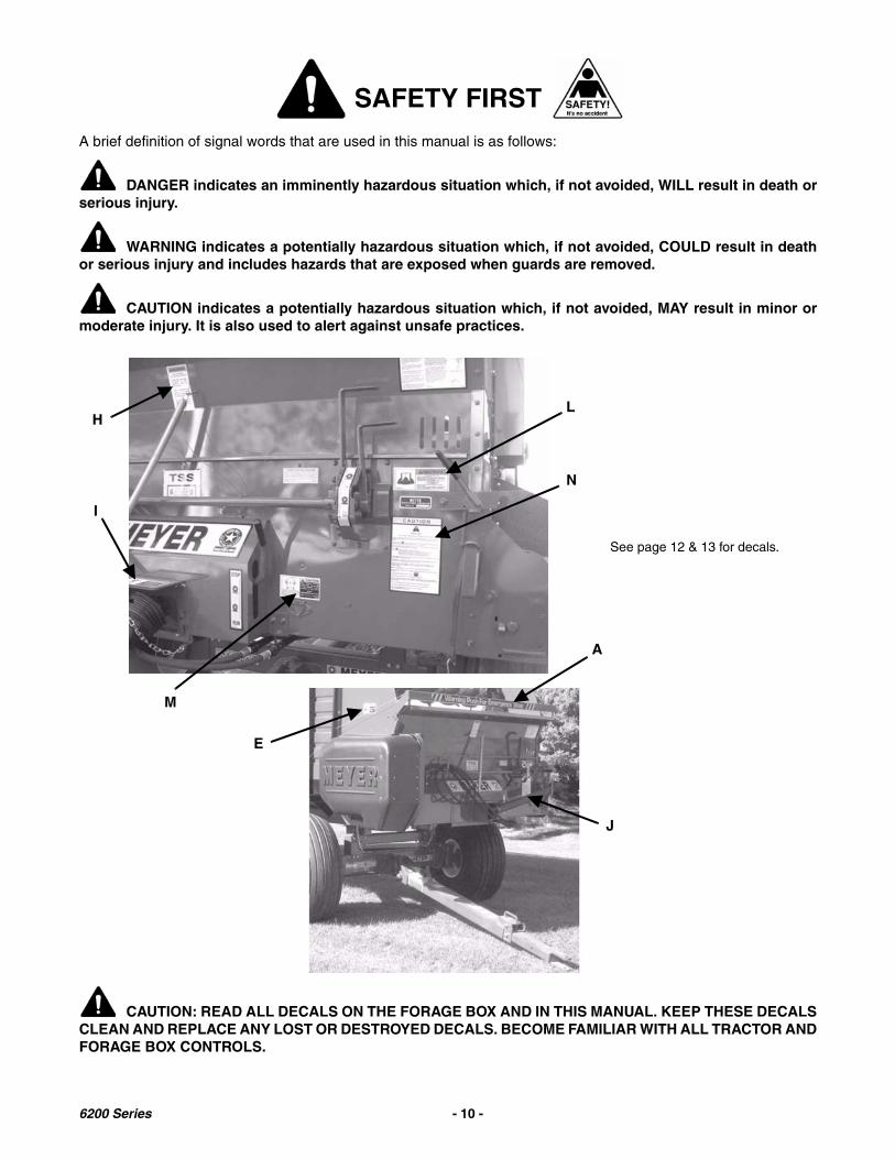
SAFETY FIRSTA brief definition of signal words that are used in this manual is as follows:
DANGER indicates an imminently hazardous situation which, if not avoided, WILL result in death orserious injury.
WARNING indicates a potentially hazardous situation which, if not avoided, COULD result in deathor serious injury and includes hazards that are exposed when guards are removed.
CAUTION indicates a potentially hazardous situation which, if not avoided, MAY result in minor ormoderate injury. It is also used to alert against unsafe practices.
CAUTION: READ ALL DECALS ON THE FORAGE BOX AND IN THIS MANUAL. KEEP THESE DECALSCLEAN AND REPLACE ANY LOST OR DESTROYED DECALS. BECOME FAMILIAR WITH ALL TRACTOR ANDFORAGE BOX CONTROLS.
See page 12 & 13 for decals.
H
I
L
N
M
E
A
J
6200 Series - 10 -
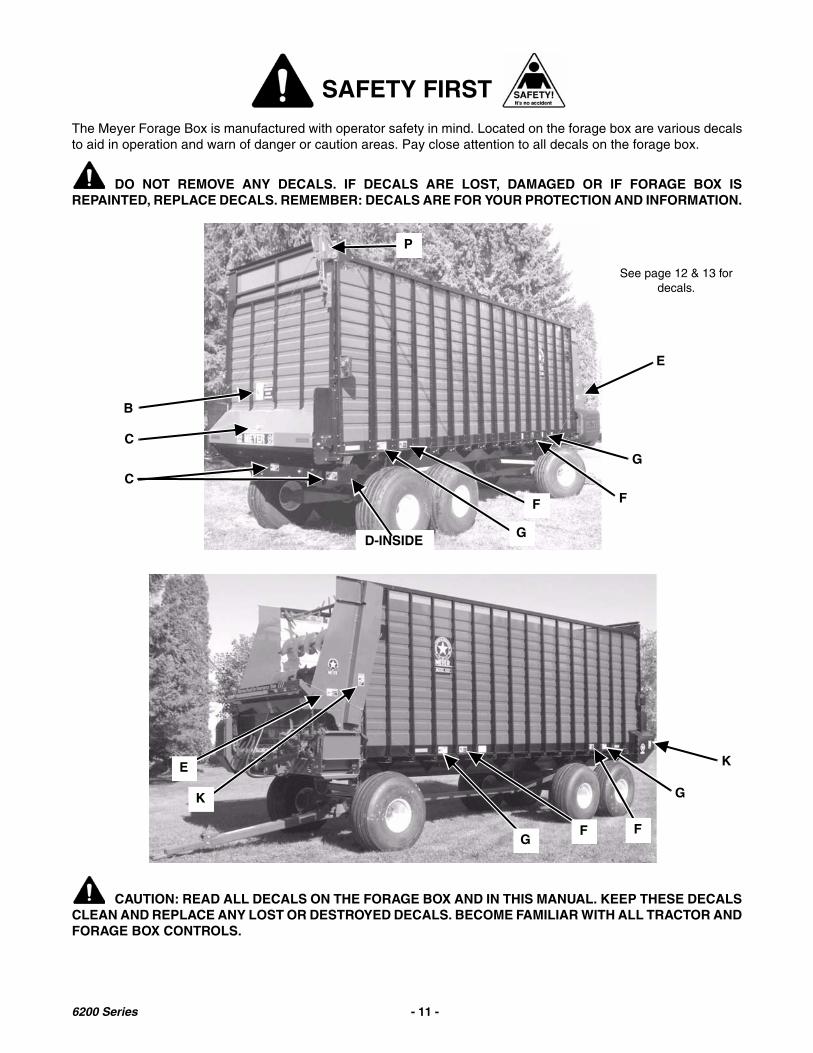
SAFETY FIRSTThe Meyer Forage Box is manufactured with operator safety in mind. Located on the forage box are various decalsto aid in operation and warn of danger or caution areas. Pay close attention to all decals on the forage box.
DO NOT REMOVE ANY DECALS. IF DECALS ARE LOST, DAMAGED OR IF FORAGE BOX ISREPAINTED, REPLACE DECALS. REMEMBER: DECALS ARE FOR YOUR PROTECTION AND INFORMATION.
CAUTION: READ ALL DECALS ON THE FORAGE BOX AND IN THIS MANUAL. KEEP THESE DECALSCLEAN AND REPLACE ANY LOST OR DESTROYED DECALS. BECOME FAMILIAR WITH ALL TRACTOR ANDFORAGE BOX CONTROLS.
B
C
C
E
G
F
D-INSIDE
G
K
See page 12 & 13 for decals.
FFG
K
E
G
P
F
6200 Series - 11 -

DECALS - 6200
A brief definition of signal words that are used in this manual is as follows:
DANGER indicates an imminently hazardous situation which, if not avoided, WILL result in death orserious injury.
WARNING indicates a potentially hazardous situation which, if not avoided, COULD result in deathor serious injury and includes hazards that are exposed when guards are removed.
CAUTION indicates a potentially hazardous situation which, if not avoided, MAY result in minor ormoderate injury. It is also used to alert against unsafe practices.
CAUTION: READ ALL DECALS ON THE FORAGE BOX AND IN THIS MANUAL. KEEP THESE DECALSCLEAN AND REPLACE ANY LOST OR DESTROYED DECALS. BECOME FAMILIAR WITH ALL TRACTOR ANDFORAGE BOX CONTROLS.
WARNING STAND CLEAR!
DOOR MAYOPEN QUICKLY!
46-0011-D
DANGER
46-0001-20
Moving Parts
Keep Away
DECAL B - 46-0011 DECAL C - 46-0001-4
DECAL H - 46-0001-72
DECAL E - 46-0001-5DECAL D - 46-0001-26
DECAL F - 46-0001-20
DECAL A - 46-0001-14 & 46-0001-15
See page 10 & 11 for decals.
DECAL G - 46-0001-71
6200 Series - 12 -

DECALS - 6200A brief definition of signal words that are used in this manual is as follows:
DANGER indicates an imminently hazardous situation which, if not avoided, WILL result in death orserious injury.
WARNING indicates a potentially hazardous situation which, if not avoided, COULD result in deathor serious injury and includes hazards that are exposed when guards are removed.
CAUTION indicates a potentially hazardous situation which, if not avoided, MAY result in minor ormoderate injury. It is also used to alert against unsafe practices.
CAUTION: READ ALL DECALS ON THE FORAGE BOX AND IN THIS MANUAL. KEEP THESE DECALSCLEAN AND REPLACE ANY LOST OR DESTROYED DECALS. BECOME FAMILIAR WITH ALL TRACTOR ANDFORAGE BOX CONTROLS.
TO PREVENT SERIOUS INJURY OR DEATHDO NOT start, operate, or work on this machine without first carefully reading andthoroughly understanding the entire contents of the operators manual. (Require thesame of all personnel who will operate this machine.)If operators manual is lost, contact your nearest Meyer Dealership or write or call:
Please give your name, address, phone number, model and serial number of your machine. A manual will be furnished.If you have any questions about operation or adjustments, and maintenance of thismachine, contact your Meyer Dealership or Meyer Mfg., Corp. before starting orcontinuing the operation of this machine.
MEYER MFG., CORP.
CAUTION
46-0001-35
WARNING
46-0001-33
KEEP ALL SHIELDSIN PLACE WHILEMACHINE ISRUNNING
WARNINGOIL INJECTION HAZARD
RELIEVE PRESSURE BEFORESERVICING.
DO NOT CHECK WITH HANDS.
IF INJURED SEEK EMERGENCYMEDICAL ATTENTION.46-8500-7 1
DECAL J - 46-0001-13
DECAL P - 46-8500-7
WARNING NOT A STEP!
This is a PTO Guard.Very serious injury
or amputationcould result from contactwith rotating PTO shaft.
46-0004-2
DECAL I - 46-0004-2
DECAL M - 46-0001-62
CAUTION
SAFETY FIRST (Do Not Operate This Machine Without Reading These Instructions)
Meyer Mfg. Corp. always takes the operator’s safety into consideration when designing farm machinery by coveringexposed moving parts for his protection; however, some areas cannot be guarded or shielded in order to assure properoperation.
If any decal becomes damaged or lost, call your dealer or our plant for replacement.Always use GENUINE MEYER replacement parts.
46-0001-22 1
Remember: The careful operator is the best operator. Most accidents are caused by human error. Certain precautions must be observed to prevent the possibility of injury or damage.
IF THE MACHINE BECOMES CLOGGED, DISENGAGE POWER TAKE-OFF, REMOVE KEYS FROM TRACTOR, AND ALLOWALL MECHANISMS TO STOP BEFORE CLEANING.
KEEP HANDS, FEET, CLOTHING, AND HAIR AWAY FROM ALL MOVING PARTS WHEN MACHINE IS IN OPERATION,LOOSE OR FLOPPY CLOTHING SHOULD NOT BE WORN BY THE OPERATOR.
STOP ENGINE, WAIT FOR ALL MOVEMENT TO STOP BEFORE LEAVING OPERATOR’S POSITION TO ADJUST,LUBRICATE, CLEAN, OR UNCLOG MACHINES. UNLESS OTHERWISE SPECIFICALLY RECOMMENDED IN THEOPERATOR’S MANUAL.
NEVER START THE MACHINE UNTIL ALL GUARDS AND SAFETY SHIELDS ARE SECURED IN PLACE.
KEEP OFF EQUIPMENT UNLESS SEAT OR PLATFORM FOR OPERATION AND OBSERVATION IS PROVIDED. KEEP ALLOTHERS OFF.
PTO SHIELD MUST ROTATE FREELY AND BE IN PLACE.
ALWAYS RUN PTO STRAIGHT IN LINE TO AVOID AN ACCIDENT BY BREAKAGE.
YOU MUST OBSERVE ALL APPLICABLE TRAFFIC LAWS WHEN TRANSPORTING ON PUBLIC ROADWAYS (WHERELEGAL TO DO SO). CHECK LOCAL LAWS FOR ALL HIGHWAY LIGHTING AND MARKING REQUIREMENTS ANDCOMPLY WITH THESE LAWS.
MAKE CERTAIN EVERYONE IS CLEAR OF MACHINE BEFORE STARTING ENGINE OR OPERATION.
PLEASE KEEP ALL DECALS AND SLOW MOVING VEHICLE SIGN CLEAN SO THEY ARE LEGIBLE.
Read the HEADS UP Rules before you operate our equipment.DO NOT allow persons other than the authorized adult operator near the machine.DO NOT clean, adjust, or lubricate the machine when any part is in operation.DO NOT pass in front of discharge area of machine when implement is in operation.Tractor PTO MUST match implement PTO. (NEVER USE PTO ADAPTERS.)
This safety alert symbol means ATTENTION! BE CAREFUL! YOUR SAFETY IS INVOLVED! It stresses an attitude of HEADS UP FOR SAFETY, also read all other decals as they are also safety warnings. DECAL K - 46-0001-33
DECAL N - 46-0001-22
DECAL L - 46-0001-35
See page 10 & 11 for decals.
6200 Series - 13 -

WARNINGWARNING: IF FOR ANY REASON THE EMERGENCY STOP MECHANISM DOES NOT FUNCTION
PROPERLY, DO NOT USE THE MACHINE UNTIL IT IS REPAIRED. FAILURE TO HEED MAY RESULT INSERIOUS PERSONAL INJURY OR DEATH.
OPERATION OF THE EMERGENCY STOP
Across the upper edge of the front unloading unit is a“Warning Push For Emergency Stop” pushbar. Bypushing on this bar during front unloading operationonly, the forage box will shut down in an emergency.
Emergency stop trip cables connected to the“Emergency Stop” pushbar extend along both sidesand down the front of the forage box. Pulling on thesetrip cables will also shut down the front unloading unitof the forage box in an emergency.
NOTE: The emergency stop mechanism DOESNOT STOP the PTO drive shaft, nor the rearunloading operation of the forage box.
WARNING: THE EMERGENCY STOPMECHANISM STOPS ONLY THE FRONTUNLOADING UNIT FROM OPERATING AND NOTTHE REAR UNLOADING OPERATION OF THEFORAGE BOX!
EMERGENCY STOP TRIP LOCATIONS
RESETTING THE EMERGENCY STOP
WARNING: DO NOT RESET THEEMERGENCY STOP MECHANISM UNTIL ALLPEOPLE, TOOLS AND OTHER OBJECTS AREWELL CLEAR OF THE FORAGE BOX. FAILURE TOHEED MAY RESULT IN SERIOUS PERSONALINJURY OR DEATH.
To reset the emergency stop mechanism, fullyengage the INDEPENDENT OUTFEED CLUTCHcontrol lever into the “RUN” position.
Check frequently to be assured that the emergencystop mechanism is in proper operating condition.Slowly engage the tractor PTO and operate the foragebox at an idle speed to ensure it is operating properly.Push the emergency stop bar across the upper edgeof the front unloading unit, to ensure that the foragebox can be shut down in an emergency.
Reset the emergency stop and recheck using theemergency stop trip cables at various locations toensure that the forage box can be shut down in anemergency. Periodically repeat emergency stopinspections during the operating season and at alltimes keep excessive slack out of the emergency stoptrip cables.EMERGENCY STOP TRIP
CABLES EXTENDING ALONG BOTH SIDES
EMERGENCY STOP TRIP CABLE UP FRONT
EMERGENCY STOP PUSH BAR
Clutch Control Lever
INDEPENDENT OUTFEED CLUTCH CONTROL LEVER
6200 Series - 14 -
PRE-OPERATIONBe certain your forage box is properly mounted to therunning gear. Consult your dealer if you have anyquestions about the tie down kit from themanufacturer and illustrated in the parts listing of thismanual.
DO NOT fill the cross conveyor unloading area withforage to get extra capacity. Overloading putsunnecessary pressures and strains on the crossconveyor and auger drive.
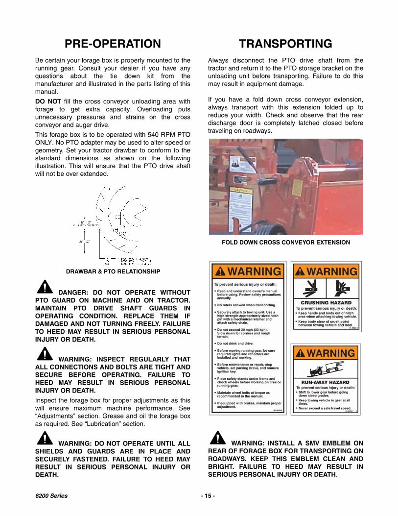
This forage box is to be operated with 540 RPM PTOONLY. No PTO adapter may be used to alter speed orgeometry. Set your tractor drawbar to conform to thestandard dimensions as shown on the followingillustration. This will ensure that the PTO drive shaftwill not be over extended.
DANGER: DO NOT OPERATE WITHOUTPTO GUARD ON MACHINE AND ON TRACTOR.MAINTAIN PTO DRIVE SHAFT GUARDS INOPERATING CONDITION. REPLACE THEM IFDAMAGED AND NOT TURNING FREELY. FAILURETO HEED MAY RESULT IN SERIOUS PERSONALINJURY OR DEATH.
WARNING: INSPECT REGULARLY THATALL CONNECTIONS AND BOLTS ARE TIGHT ANDSECURE BEFORE OPERATING. FAILURE TOHEED MAY RESULT IN SERIOUS PERSONALINJURY OR DEATH.
Inspect the forage box for proper adjustments as thiswill ensure maximum machine performance. See“Adjustments” section. Grease and oil the forage boxas required. See “Lubrication” section.
WARNING: DO NOT OPERATE UNTIL ALLSHIELDS AND GUARDS ARE IN PLACE ANDSECURELY FASTENED. FAILURE TO HEED MAYRESULT IN SERIOUS PERSONAL INJURY ORDEATH.
TRANSPORTINGAlways disconnect the PTO drive shaft from thetractor and return it to the PTO storage bracket on theunloading unit before transporting. Failure to do thismay result in equipment damage.
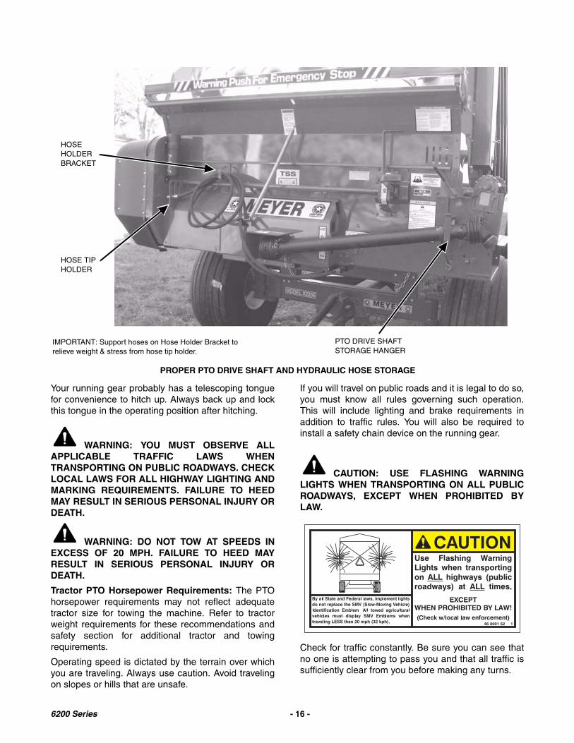
If you have a fold down cross conveyor extension,always transport with this extension folded up toreduce your width. Check and observe that the reardischarge door is completely latched closed beforetraveling on roadways.
WARNING: INSTALL A SMV EMBLEM ONREAR OF FORAGE BOX FOR TRANSPORTING ONROADWAYS. KEEP THIS EMBLEM CLEAN ANDBRIGHT. FAILURE TO HEED MAY RESULT INSERIOUS PERSONAL INJURY OR DEATH.
DRAWBAR & PTO RELATIONSHIP
FOLD DOWN CROSS CONVEYOR EXTENSION
6200 Series - 15 -
Your running gear probably has a telescoping tonguefor convenience to hitch up. Always back up and lockthis tongue in the operating position after hitching.
WARNING: YOU MUST OBSERVE ALLAPPLICABLE TRAFFIC LAWS WHENTRANSPORTING ON PUBLIC ROADWAYS. CHECKLOCAL LAWS FOR ALL HIGHWAY LIGHTING ANDMARKING REQUIREMENTS. FAILURE TO HEEDMAY RESULT IN SERIOUS PERSONAL INJURY ORDEATH.
WARNING: DO NOT TOW AT SPEEDS INEXCESS OF 20 MPH. FAILURE TO HEED MAYRESULT IN SERIOUS PERSONAL INJURY ORDEATH.
Tractor PTO Horsepower Requirements: The PTOhorsepower requirements may not reflect adequatetractor size for towing the machine. Refer to tractorweight requirements for these recommendations andsafety section for additional tractor and towingrequirements.
Operating speed is dictated by the terrain over whichyou are traveling. Always use caution. Avoid travelingon slopes or hills that are unsafe.
If you will travel on public roads and it is legal to do so,you must know all rules governing such operation.This will include lighting and brake requirements inaddition to traffic rules. You will also be required toinstall a safety chain device on the running gear.
CAUTION: USE FLASHING WARNINGLIGHTS WHEN TRANSPORTING ON ALL PUBLICROADWAYS, EXCEPT WHEN PROHIBITED BYLAW.
Check for traffic constantly. Be sure you can see thatno one is attempting to pass you and that all traffic issufficiently clear from you before making any turns.
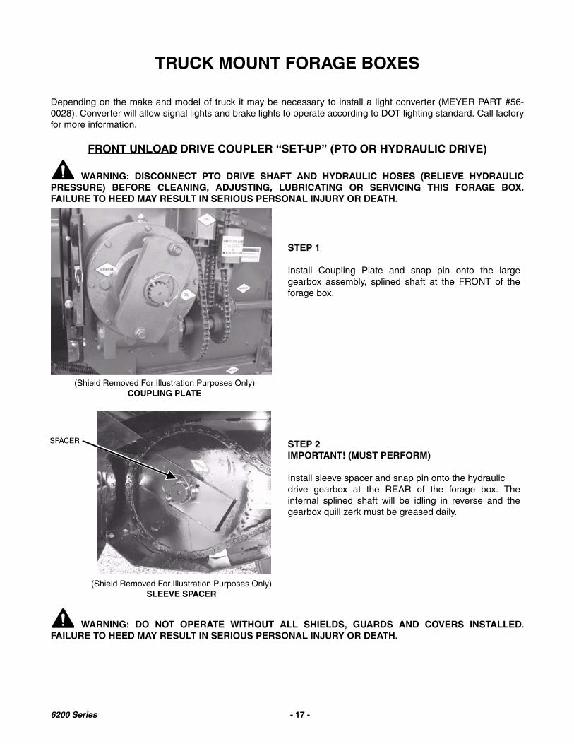
PROPER PTO DRIVE SHAFT AND HYDRAULIC HOSE STORAGE
PTO DRIVE SHAFT STORAGE HANGER
IMPORTANT: Support hoses on Hose Holder Bracket to relieve weight & stress from hose tip holder.
HOSE TIP HOLDER
HOSE HOLDER BRACKET
6200 Series - 16 -
TRUCK MOUNT FORAGE BOXES
Depending on the make and model of truck it may be necessary to install a light converter (MEYER PART #56-0028). Converter will allow signal lights and brake lights to operate according to DOT lighting standard. Call factoryfor more information.
FRONT UNLOAD DRIVE COUPLER “SET-UP” (PTO OR HYDRAULIC DRIVE)
WARNING: DISCONNECT PTO DRIVE SHAFT AND HYDRAULIC HOSES (RELIEVE HYDRAULICPRESSURE) BEFORE CLEANING, ADJUSTING, LUBRICATING OR SERVICING THIS FORAGE BOX.FAILURE TO HEED MAY RESULT IN SERIOUS PERSONAL INJURY OR DEATH.
WARNING: DO NOT OPERATE WITHOUT ALL SHIELDS, GUARDS AND COVERS INSTALLED.FAILURE TO HEED MAY RESULT IN SERIOUS PERSONAL INJURY OR DEATH.
(Shield Removed For Illustration Purposes Only)COUPLING PLATE
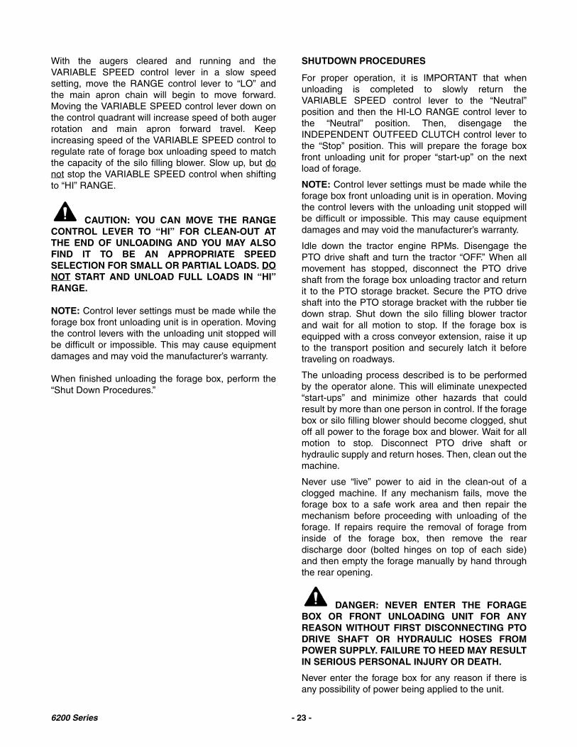
STEP 1
Install Coupling Plate and snap pin onto the largegearbox assembly, splined shaft at the FRONT of theforage box.
(Shield Removed For Illustration Purposes Only)SLEEVE SPACER
STEP 2IMPORTANT! (MUST PERFORM)
Install sleeve spacer and snap pin onto the hydraulicdrive gearbox at the REAR of the forage box. Theinternal splined shaft will be idling in reverse and thegearbox quill zerk must be greased daily.
SPACER
6200 Series - 17 -

Operating Procedures: See Front Unload “VARIABLE SPEED OPERATION with IOC” Page 21.
#37-0010 COUPLING PLATE ASSEMBLY COMPLETE
KEY PART NO. DESCRIPTION1 37-0015 Splined Drive Plate2 831-7516-2 Drive Bolt, 3/4-16 x 2 Allen
Head GR83 844-7516 3/4-16 Flange Top Lock Nut4 43-0025 Idler Sleeve Spacer5 823-0004 Snap Pin
GEARBOX PLATE
6200 Series - 18 -

REAR UNLOAD DRIVE COUPLER “SET-UP” (PTO OR HYDRAULIC DRIVE)
WARNING: DISCONNECT PTO DRIVE SHAFT AND HYDRAULIC HOSES (RELIEVE HYDRAULICPRESSURE) BEFORE CLEANING, ADJUSTING, LUBRICATING OR SERVICING THIS FORAGE BOX.FAILURE TO HEED MAY RESULT IN SERIOUS PERSONAL INJURY OR DEATH.
WARNING: DO NOT OPERATE WITHOUT ALL SHIELDS, GUARDS AND COVERS INSTALLED.FAILURE TO HEED MAY RESULT IN SERIOUS PERSONAL INJURY OR DEATH.
(Shield Removed For Illustration Purposes Only)COUPLING PLATE
STEP 1
Install Coupling Plate and snap pin onto the largegearbox assembly on the splined shaft at the REAR ofthe forage box.
NOTE: The rear unloading gearbox and hydraulicallydriven motor, hydraulic return line features a checkvalve to protect and prevent any accidental damage bymistakenly, or incorrectly coupling hydraulic hoses tothe tractor. The check valve is equipped with a reverseflow feature which will allow the box to run in a reversedirection for drive plate removal. Reverse hydraulic flowapproximately 10-15 seconds to rotate gearbox driveplate away from the removable drive plate. DO NOTRUN IN REVERSE FOR UNLOADING!
(Shield Removed For Illustration Purposes Only)SLEEVE SPACER
STEP 2IMPORTANT! (MUST PERFORM)
Install sleeve spacer and snap pin onto the largegearbox assembly, splined shaft at the FRONT of theforage box. The internal splined shaft will be idling inreverse and the gearbox quill zerk must be greaseddaily.
6200 Series - 19 -

Operating Procedures: See “REAR UNLOAD OPERATION” (HYD or PTO) Page 24
.
INDEPENDENT OUTFEED CLUTCH LEVER
STEP 3
Move the Independent Outfeed Clutch lever to “STOP”(UP).
NOTE: The PTO driven Independent Outfeed Clutchcan be used to clean out accumulation of forage fromthe front unit cross conveyor without changing the drivecoupler for forage box rear unloading.
HYDRAULIC CHECK VALVE AT REAR OF BOX
STEP 4 (HYDRAULIC DRIVE)
Couple both supply and return line hydraulic hoses ofthe forage box to the hydraulic outlets of the towingtractor.
NOTE: The rear unloading gearbox and hydraulic drivenmotor, hydraulic return line features a check valve toprotect and prevent any accidental damage bymistakenly, or incorrectly coupling hydraulic hoses tothe tractor. The check valve makes it impossible to runthe main apron chain in the wrong direction and causedamage to the forage box.
HYDRAULIC MOTORCHECK
6200 Series - 20 -

FRONT UNLOAD VARIABLE SPEED OPERATION WITH INDEPENDENT OUTFEED CLUTCH
FORAGE BOX CONTROL LEVERS
WARNING: NEITHER THE VARIABLESPEED NOR THE HI-LO RANGE CONTROL LEVERWILL DISENGAGE THE CROSS CONVEYOR. ONLYTHE TRACTOR PTO, INDEPENDENT OUTFEEDCLUTCH, OR EMERGENCY STOP MECHANISMWILL STOP THE CROSS CONVEYOR. FAILURE TOHEED MAY RESULT IN SERIOUS PERSONALINJURY OR DEATH.
Facing the front of the forage box, the lower most RHcontrol lever is the INDEPENDENT OUTFEEDCLUTCH control. Moving this control lever down intothe “Run” position engages the cross conveyor andmain drive mechanism. Engage this control lever intothe “Run” position for normal operation. Once thiscontrol lever is engaged, it acts as the emergencystop when pushing on the “Warning Push forEmergency Stop” push bar or when pulling on theemergency stop trip cables.
The LH control lever is the VARIABLE SPEED control.Moving this control lever regulates rotational speed ofthe unloading augers and the forward speed of themain apron chains, in conjunction with the HI-LORANGE control. At the uppermost notch on the controlquadrant, the VARIABLE SPEED control is in“Neutral” position. In this position, neither the mainapron chains advance, nor do the unloading augersrotate under load, regardless of the position of the HI-LO RANGE control. Moving the VARIABLE SPEEDcontrol lever down on the control quadrant increasesspeed of both auger rotation and main apron chainforward travel.
The RH control lever is the HI-LO RANGE control.Center detent is the “Neutral” position. Shifting thelever up on the control quadrant is “LO” RANGE andshifting the lever fully down is “HI” RANGE. Rangeselection affects the forward speed of the main apronchains only. In the “Neutral” position, the main apronchain does not travel forward.
Three levers control operating the front unloading unitof the forage box.
1. INDEPENDENT OUTFEED CLUTCH - IOC2. VARIABLE SPEED3. “HI-LO RANGE”
DECAL #46-0001-64
IOC CONTROL LEVER
HI-LO RANGE CONTROLVARIABLE
SPEED CONTROL
6200 Series - 21 -

UNLOADING THE FORAGE BOX
Pull the forage box into position and park so that thecross conveyor discharge opening is in alignment withthe silo filling blower hopper. If the forage box isequipped with a fold down cross conveyor extension,it can be lowered before pulling in front of the blower.After a couple of parking trails, you may becomefamiliar with the correct parking place and be able tolower the cross conveyor extension after parking.Always park the forage box and unloading tractor in astraight line. Minimize the unloading angle on the PTOdrive shaft to prevent wearing of universal joints whenconnected to the unloading tractor PTO. Shift theunloading tractor to “Neutral” or “Park” and set thebrakes.
NOTE: Normal operation is using a farm tractor. Ifusing some other vehicle, exercise equivalent cautionwhen parking and exiting this vehicle.
Properly dismount from the tractor and approach theforage box by walking along the left side of the tractoras shown in the following diagram. Do not approachthe forage box from the right side of the machine (lefthand unload). Approach the left front area of theforage box, as this is where the control levers arelocated. Standing in the operator position will notrequire crossing the PTO drive shaft at any timeduring the unloading operation.
OPERATOR TRAFFIC PATTERN
WARNING: DO NOT STEP OVER THE PTODRIVE SHAFT. STAY WELL CLEAR OF THE PTOAT ALL TIMES. FAILURE TO HEED MAY RESULTIN SERIOUS PERSONAL INJURY OR DEATH.
WARNING: DO NOT STEP UP ON ANYPART OF THE FORAGE BOX AT ANY TIME.FAILURE TO HEED MAY RESULT IN SERIOUSPERSONAL INJURY OR DEATH.
START UP PROCEDURES
Remove PTO drive shaft from the forage box PTOstorage bracket and connect to the tractor PTO. Besure the PTO yoke is securely locked to the tractorPTO. If using an optional hydraulic drive, couple thehydraulic hoses to the power supply.
Check that the INDEPENDENT OUTFEED CLUTCHcontrol lever is in the “Stop” position and theVARIABLE SPEED & HI-LO RANGE control leversare in the “Neutral” positions.
NOTE: The INDEPENDENT OUTFEED CLUTCH,VARIABLE SPEED, and HI-LO RANGE control leversmust be in their “Stop” or “Neutral” positions whenengaging and disengaging the PTO drive shaft (oroptional hydraulic drive). All forage box control leverselections are to be made while the PTO (orhydraulic) power is in operation. If the control leversare engaged before power is applied, damage mayoccur to the Variable Speed drive or IndependentOutfeed Clutch drive or both. Failure to follow correctoperating procedures may cause equipment damageand may void the manufacturer’s warranty.
At this time, start the silo filling blower. Return to theforage box unloading tractor, slowly engage the PTO,and set the engine speed from 1300-1500 RPM togive a PTO speed of 300-375 RPM.
Return to the operator’s position adjacent to theforage box controls. Intermittently engage theINDEPENDENT OUTFEED CLUTCH control lever tothe “Run” position and allow the cross conveyor toempty out any accumulation of forage in the frontunloading unit. After the forage has emptied, fullyengage the INDEPENDENT OUTFEED CLUTCHcontrol lever into the “Run” position.
Next, engage the VARIABLE SPEED control lever toclear forage from the three unloading augers.Intermittently move the lever between “Neutral” andthe 1st and/or 2nd notch settings on the controlquadrant. This will engage and disengage the augersat a slow speed to clear them without the main apronmoving forward; because the HI-LO RANGE controllever is still in “Neutral.”
LH Side
RH Side
Operator Position
6200 Series - 22 -
With the augers cleared and running and theVARIABLE SPEED control lever in a slow speedsetting, move the RANGE control lever to “LO” andthe main apron chain will begin to move forward.Moving the VARIABLE SPEED control lever down onthe control quadrant will increase speed of both augerrotation and main apron forward travel. Keepincreasing speed of the VARIABLE SPEED control toregulate rate of forage box unloading speed to matchthe capacity of the silo filling blower. Slow up, but donot stop the VARIABLE SPEED control when shiftingto “HI” RANGE.
CAUTION: YOU CAN MOVE THE RANGECONTROL LEVER TO “HI” FOR CLEAN-OUT ATTHE END OF UNLOADING AND YOU MAY ALSOFIND IT TO BE AN APPROPRIATE SPEEDSELECTION FOR SMALL OR PARTIAL LOADS. DONOT START AND UNLOAD FULL LOADS IN “HI”RANGE.
NOTE: Control lever settings must be made while theforage box front unloading unit is in operation. Movingthe control levers with the unloading unit stopped willbe difficult or impossible. This may cause equipmentdamages and may void the manufacturer’s warranty.
When finished unloading the forage box, perform the“Shut Down Procedures.”
SHUTDOWN PROCEDURES
For proper operation, it is IMPORTANT that whenunloading is completed to slowly return theVARIABLE SPEED control lever to the “Neutral”position and then the HI-LO RANGE control lever tothe “Neutral” position. Then, disengage theINDEPENDENT OUTFEED CLUTCH control lever tothe “Stop” position. This will prepare the forage boxfront unloading unit for proper “start-up” on the nextload of forage.
NOTE: Control lever settings must be made while theforage box front unloading unit is in operation. Movingthe control levers with the unloading unit stopped willbe difficult or impossible. This may cause equipmentdamages and may void the manufacturer’s warranty.
Idle down the tractor engine RPMs. Disengage thePTO drive shaft and turn the tractor “OFF.” When allmovement has stopped, disconnect the PTO driveshaft from the forage box unloading tractor and returnit to the PTO storage bracket. Secure the PTO driveshaft into the PTO storage bracket with the rubber tiedown strap. Shut down the silo filling blower tractorand wait for all motion to stop. If the forage box isequipped with a cross conveyor extension, raise it upto the transport position and securely latch it beforetraveling on roadways.
The unloading process described is to be performedby the operator alone. This will eliminate unexpected“start-ups” and minimize other hazards that couldresult by more than one person in control. If the foragebox or silo filling blower should become clogged, shutoff all power to the forage box and blower. Wait for allmotion to stop. Disconnect PTO drive shaft orhydraulic supply and return hoses. Then, clean out themachine.
Never use “live” power to aid in the clean-out of aclogged machine. If any mechanism fails, move theforage box to a safe work area and then repair themechanism before proceeding with unloading of theforage. If repairs require the removal of forage frominside of the forage box, then remove the reardischarge door (bolted hinges on top of each side)and then empty the forage manually by hand throughthe rear opening.
DANGER: NEVER ENTER THE FORAGEBOX OR FRONT UNLOADING UNIT FOR ANYREASON WITHOUT FIRST DISCONNECTING PTODRIVE SHAFT OR HYDRAULIC HOSES FROMPOWER SUPPLY. FAILURE TO HEED MAY RESULTIN SERIOUS PERSONAL INJURY OR DEATH.
Never enter the forage box for any reason if there isany possibility of power being applied to the unit.
6200 Series - 23 -

REAR UNLOAD OPERATION PTO OR HYDRAULIC DRIVE
WARNING: MAKE CERTAIN EVERYONE ISWELL CLEAR OF EQUIPMENT BEFOREAPPLYING POWER. FAILURE TO HEED MAYRESULT IN SERIOUS PERSONAL INJURY ORDEATH.
Always park the forage box and unloading tractor in astraight line. Minimize the unloading angle on the PTOdrive shaft to prevent wearing of universal joints whenconnected to the unloading tractor PTO. Shift theunloading tractor to “Neutral” or “Park” and set thebrakes.
NOTE: Normal operation is using a farm tractor. Ifusing some other vehicle, exercise caution whenparking and exiting this vehicle.
Remove the PTO drive shaft from the forage box PTOstorage bracket and connect it to the tractor PTO. Besure the PTO yoke is securely locked to the tractorPTO. Move the Independent Outfeed Clutch controllever to the “Stop” position. If using a hydraulic drive,couple the hydraulic hoses to the power supply. Besure the hydraulic hoses are securely locked to thetractor hydraulic couplers.
CAUTION (QUICK RELEASE!)
Make sure all persons are well clear of the forage boxand the unloading area.
The rear discharge door opens automatically byreleasing its latches as the main aprons begin tomove. The rear discharge door can spring open withextreme force when its latches release. Pressure offorage against the rear door causes it to spring openvery quickly.
WARNING: THE REAR DISCHARGE DOORCAN SPRING OPEN QUICKLY AND WITHEXTREME FORCE. KEEP ALL PERSONS WELLCLEAR OF THE FORAGE BOX AND UNLOADINGAREA. FAILURE TO HEED MAY RESULT INSERIOUS PERSONAL INJURY OR DEATH.
Return to the tractor, restart, and SLOWLY engagethe tractor PTO or hydraulics to start the apron chainsand to open the rear door. Once the door opens,regulate the discharge flow with the tractor enginespeed. Do not operate above rated tractor engineRPM speed.
Unloading is best observed from the tractor seat.Keep moving the forage box forward to prevent silagefrom being carried underneath into the main apronchain return area.
REAR DISCHARGE DOOR
HINGE BOLTS
REAR OPENING DISCHARGE DOOR REAR DISCHARGE DOOR LATCH(Typical both sides)
6200 Series - 24 -

WARNING: DO NOT STEP UP ON ANYPART OF THE FORAGE BOX AT ANY TIME.FAILURE TO HEED MAY RESULT IN SERIOUSPERSONAL INJURY OR DEATH.
When finished unloading, reduce engine speed to idleand disengage the tractor PTO or hydraulics. Pull theforage box straight ahead to pull the rear door awayfrom the unloaded pile of forage. Gravity will allow therear door to swing shut. The rear door latches willengage to secure it closed. Visibly observe that reardischarge door properly latches closed.
The unloading process described is to be performedby the operator alone. This will eliminate unexpected“start-ups” and minimize other hazards that couldresult by more than one person in control. If the foragebox should become clogged, shut off all power to theforage box and wait for all motion to stop. DisconnectPTO drive shaft or hydraulic supply and return hosesand then clean out the machine.
Never use “live” power to aid in the clean-out of aclogged machine. If any mechanism fails, move theforage box to a safe work area and then repair themechanism before proceeding with unloading of theforage. If repairs require removal of forage from insideof the forage box, then remove the rear dischargedoor (bolted hinges on top of each side) and thenempty the forage manually by hand through the rearopening.
DANGER: NEVER ENTER THE FORAGEBOX OR FRONT UNLOADING UNIT FOR ANYREASON WITHOUT FIRST DISCONNECTING THEPTO DRIVE SHAFT OR HYDRAULIC HOSES FROMPOWER SUPPLY. FAILURE TO HEED MAY RESULTIN SERIOUS PERSONAL INJURY OR DEATH.
Never enter the forage box for any reason if there isany possibility of power being applied to the unit.
CAUTION (QUICK RELEASE!)
HINGE BOLTS
REAR DISCHARGEDOOR
REAR OPENING DISCHARGE DOOR
6200 Series - 25 -

LUBRICATIONWARNING: DISCONNECT PTO DRIVE SHAFT (OR HYDRAULIC POWER SOURCE) BEFORE
CLEANING, ADJUSTING, LUBRICATING OR SERVICING THIS MACHINE. FAILURE TO HEED MAY RESULTIN SERIOUS PERSONAL INJURY OR DEATH.
DAILY LUBRICATION(every 8-10 loads)
Grease (2) PTO drive shaft universal joints (not illustrated). Grease (1) PTO drive shaft telescoping shaft andtube. Zerk accessible through the plastic guards (not illustrated).
Grease front idler sprocket - wipe off excess grease from exterior.
Grease (2) moveable clutch sheaves - wipe excess from interior and exterior. Prevent oil and grease fromgetting on clutch sheave belt drive surface.
Apply grease to lower cluster shaft end and lower variable speed engagement arm.
Oil (2) roller chains and “HI-LO” range sliding jaw clutch.
Grease “HI-LO” range brass shifting collar.
Oil (3) roller chains on auger drive and (1) roller chain on cross conveyor drive. Open the auger chain coverto oil the chains.
Grease (2) gearbox hollow output shaft zerks (1 Front, 1 Rear - (not shown) zerk located behind couplingplate).
BEGINNING OF CROP MAINTENANCE(approximately 100-150 loads)
Grease (4) main apron shaft bearings (2 Front, 2 Rear) (Front center bearing grease from zerk in left endframe).
Grease (3) shifter control lever guide sleeves. Grease (1) Independent Outfeed Clutch handle pivot underfront shield.
Grease (4) gear cluster shaft bearings.
Grease (2) rear gate hinges. Oil (2) rear gate latch pivot bolts.
Maintain oil in the front and rear main apron drive (2) gearboxes at the check plug level. Change oil in thegearboxes after the first season of use and yearly thereafter. Use #85W140 wt. Gear Lube Oil. Lighter oilmay be used in temperatures below 20° F.
Maintain oil in the auger drive upper gearbox at the check plug level. Change oil in the gearbox after the firstseason of use and yearly thereafter. Use ONLY Synthetic ISO 460 Gear Oil AGMA 7 (Non EP) or equivalent.
Grease (4) Cross Conveyor Apron Shaft Bearings
Adjust main apron chain per “Adjustments” section. Adjust cross conveyor chain per “Adjustments” section.
Adjust shifter controls per “Adjustments” section.
Remove panel and clean out accumulation of foreign material build-up.
L1
L2
L3
L4
L5
L6
L7
L8
L9
L10
L11
L12
L13
L14
L15
A1
A2
A3
6200 Series - 26 -

END OF CROP CLEANUP ANDMAINTENANCEAllow box to completely clean out last load of forage.Clean out all forage material from inside the box, roofand on the outside of the box. Clean the front crossconveyor on the top pan and in the lower pan (chainreturn) area. Clear out the clean-out panel. Clean outthe deflector shield at the rear of the box, both insideand outside.
It is recommended to lube the forage box beforestorage to exclude moisture from bearings. Apply oil toroller chain drives and to the main apron chains andcross conveyor chains. Also, new or used oil isrecommended to be applied to the floor and inside ofthe box walls.
It is also a good time to inspect all adjustments andcheck for parts that need repair or replacement.Performing these tasks now will guarantee that theforage box is ready for use at the beginning of the nextseason.
Equivalent Viscosity of ISO-VG Grades at 104°Fand SAE Gear Lube Grades
LUBRICATION DIAGRAMS(Shields Removed for Illustration Purposes Only)
L8
L13
L14
L15 A3
L11
L15 L2 L7
L4
L6
L5 L11 L3
UNDER SHIELD
L10
L10
L7
L9
L9
L12
BOTH SIDES
ISO-VG Grade SAE Gear Lube Grade
46 75W
100 80W-90
220 90
460 85W-140
1500 250
L15
6200 Series - 27 -

TWO-SPEED OPERATION
CONTROL LEVER
WARNING: THE RANGE CONTROL LEVERDOES NOT STOP THE CROSS APRON. ONLY THETRACTOR PTO OR THE EMERGENCY STOPMECHANISM WILL STOP THE CROSSCONVEYOR. FAILURE TO HEED MAY RESULT INSERIOUS PERSONAL INJURY OR DEATH.
The unloading of the forage box is controlled by therange control lever and the tractor PTO speed.
Center detent on the range control is “NEUTRAL”, upis “LOW” and down is “HIGH” range. Range selectionaffects the forward speed of the main apron chainonly. In neutral, the apron does not advance.
UNLOADING THE FORAGE BOX
Pull the forage box into position and park so that thecross conveyor discharge opening is in alignment withthe silo filling blower hopper. If the forage box isequipped with a fold down conveyor extension, it canbe lowered before pulling in front of the blower. After acouple of parking trials, you may become familiar withthe correct parking place and be able to lower thecross conveyor extension after parking. Always parkthe forage box and unloading tractor in a straight line.Minimize the unloading angle on the PTO drive shaftto prevent wearing of universal joints when connectedto the unloading tractor PTO. Shift the unloadingtractor to “Neutral” or “Park” and set the brakes.
NOTE: Normal operation is using a tractor. If usingsome other vehicle exercise equivalent caution whenparking and exiting this vehicle.
Properly dismount from the tractor and approach theforage box by walking along the left side of the tractoras shown in the following diagram. Do not approachthe forage box from the right side of the machine (lefthand unload). Approach the left front area of theforage box, as this is where the control levers arelocated. Standing in the operator position will notrequire crossing the PTO drive shaft at any timeduring the unloading operation.
WARNING: DO NOT STEP OVER THE PTODRIVESHAFT. STAY WELL CLEAR OF THE PTO ATALL TIMES. FAILURE TO HEED MAY RESULT INSERIOUS PERSONAL INJURY OR DEATH.
WARNING: DO NOT STEP UP ON ANY PART OFTHE FORAGE BOX AT ANY TIME. FAILURE TOHEED MAY RESULT IN SERIOUS PERSONALINJURY OF DEATH.
RANGE CONTROL LEVER OPERATOR TRAFFIC PATTERN
LH Side
RH Side
Operator Position
6200 Series - 28 -
START UP PROCEDURES:
Remove the PTO drive shaft from the forage box PTOstorage bracket and connect it to the tractor PTO. Besure the PTO yoke is securely locked to the tractorPTO. If using an optional hydraulic drive, couple thehydraulic hoses to the power supply.
Check that the INDEPENDENT OUTFEED CLUTCHcontrol lever is in the “Stop” position and the HI-LORANGE control lever is in the “Neutral” position.
NOTE: The INDEPENDENT OUTFEED CLUTCH andHI-LO RANGE control levers must be in their “Stop” or“Neutral” positions when engaging and disengagingthe PTO drive shaft (or optional hydraulic drive). Allforage box control lever selections are to be madewhile the PTO (or hydraulic) power is in operation. Ifthe control levers are engaged before power isapplied, damage may occur to the IndependentOutfeed Clutch drive. Failure to follow correctoperating procedures may cause equipment damageand may void the manufacturer’s warranty.
At this time, start the silo filling blower. Return to theforage box unloading tractor, slowly engage the PTO,and set the engine speed from 1300-1500 RPM togive a PTO speed of 300-375 RPM.
Return to the operator’s position adjacent to theforage box controls. Intermittently engage theINDEPENDENT OUTFEED CLUTCH control leverinto the “Run” position and allow the cross conveyor toempty out any accumulation of forage in the frontunloading unit. After the forage has emptied, fullyengage the INDEPENDENT OUTFEED CLUTCHcontrol lever into the “Run” position.
Next, move the RANGE control lever to “LO” and themain apron chain will begin to move forward.
IMPORTANT: YOU CAN MOVE THE RANGECONTROL LEVER TO “HI” FOR CLEAN-OUT ATTHE END OF UNLOADING AND YOU MAY ALSOFIND IT TO BE AN APPROPRIATE SPEEDSELECTION FOR SMALL OR PARTIAL LOADS. DONOT START AND UNLOAD FULL LOADS IN “HI”RANGE.
NOTE: Control lever settings must be made while theforage box front unloading unit is in operation. Movingthe control levers with the unloading unit stopped willbe difficult or impossible. This may cause equipmentdamages and may void the manufacturer’s warranty.
When finished unloading the forage box, perform the“Shut Down Procedures.” Refer to page 23.
6200 Series - 29 -

TWO SPEED LUBRICATION AND MAINTENANCEWARNING: DISCONNECT PTO DRIVE SHAFT (OR OPTIONAL HYDRAULIC POWER SOURCE)
BEFORE CLEANING, ADJUSTING, LUBRICATING OR SERVICING THIS MACHINE. FAILURE TO HEED MAYRESULT IN SERIOUS PERSONAL INJURY OR DEATH.
ROLLER CHAIN DRIVES
The roller chain drives are tensioned by automaticspring loaded tension blocks.
RANGE CONTROL CLUTCH ENGAGEMENT
With the range control lever set to neutral, theengaging jaw clutch should be about midway betweenthe “LO and “HI” sprocket clutch jaws on the splinedshaft. Neither should be engaged. When the lever ismoved to “LO” the engaging jaw clutch should matewith “LO” speed sprocket clutch and have about 1/16”of clearance. Likewise for the “HI” speed when thelever is moved to “HI”. This engagement is adjusted bychanging the length of over-lap on the two, slottedhole linkage bars.
DAILY LUBRICATION MAINTENANCE(every 8-10 loads)
Grease PTO drive shaft joints (not illustrated).
Grease front idler sprocket - wipe off excessgrease from exterior.
Oil roller chains and HI-LO range jaw clutch.
Oil roller chains on auger drive and crossconveyor drive.
Oil or grease HI-LO range brass shifting collar.
BEGINNING OF CROP MAINTENANCE(approximately 100-150 loads)
Grease main shaft bearings. (Not Shown)
Grease range control sleeve.
Grease gear cluster shaft bearings.
Maintain oil level in gear boxes. See L13 & L14.
Grease (4) Cross Conveyor Apron ShaftBearings, see page 26.
Adjust range control per “Clutch Engagement”.
END OF CROP CLEANUP AND MAINTENANCE
Clean out all forage material from inside the box, roof,and on the outside of the box. Clean the front crossapron on the top and in the lower pan (chain return)area. Clean out the deflector shield at the rear of thebox, both inside and outside.
New or used oil is recommended to be applied to thefloor and inside of the box walls. Also coat all apronchains and slats with oil.
L1
L2
L3
L4
L5
L6
L7
L8
L11
L15
A2
L4
6200 Series - 30 -
ADJUSTMENTSWARNING: DISCONNECT PTO DRIVE SHAFT (OR HYDRAULIC POWER SOURCE) BEFORE
CLEANING, ADJUSTING, LUBRICATING OR SERVICING THIS MACHINE. FAILURE TO HEED MAY RESULTIN SERIOUS PERSONAL INJURY OR DEATH.
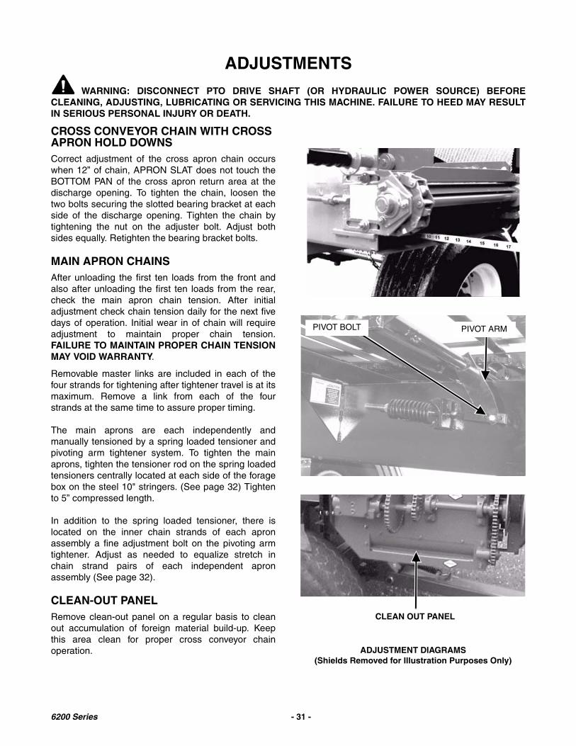
CROSS CONVEYOR CHAIN WITH CROSS APRON HOLD DOWNSCorrect adjustment of the cross apron chain occurswhen 12” of chain, APRON SLAT does not touch theBOTTOM PAN of the cross apron return area at thedischarge opening. To tighten the chain, loosen thetwo bolts securing the slotted bearing bracket at eachside of the discharge opening. Tighten the chain bytightening the nut on the adjuster bolt. Adjust bothsides equally. Retighten the bearing bracket bolts.
MAIN APRON CHAINSAfter unloading the first ten loads from the front andalso after unloading the first ten loads from the rear,check the main apron chain tension. After initialadjustment check chain tension daily for the next fivedays of operation. Initial wear in of chain will requireadjustment to maintain proper chain tension.FAILURE TO MAINTAIN PROPER CHAIN TENSIONMAY VOID WARRANTY.
Removable master links are included in each of thefour strands for tightening after tightener travel is at itsmaximum. Remove a link from each of the fourstrands at the same time to assure proper timing.
The main aprons are each independently andmanually tensioned by a spring loaded tensioner andpivoting arm tightener system. To tighten the mainaprons, tighten the tensioner rod on the spring loadedtensioners centrally located at each side of the foragebox on the steel 10" stringers. (See page 32) Tightento 5” compressed length.
In addition to the spring loaded tensioner, there islocated on the inner chain strands of each apronassembly a fine adjustment bolt on the pivoting armtightener. Adjust as needed to equalize stretch inchain strand pairs of each independent apronassembly (See page 32).
CLEAN-OUT PANELRemove clean-out panel on a regular basis to cleanout accumulation of foreign material build-up. Keepthis area clean for proper cross conveyor chainoperation.
PIVOT BOLT PIVOT ARM
ADJUSTMENT DIAGRAMS(Shields Removed for Illustration Purposes Only)
CLEAN OUT PANEL
6200 Series - 31 -

ADJUSTMENT OF 6200 SERIES MAIN APRON CHAINS
A. For Regular Tightening:
IMPORTANT AT ALL TIMES OF OPERATION!Correct apron tension occurs when the return mainapron slats ride 2" at mid span off of the front pair ofwooden slide rails and only one apron slat touches atmid span on the rear pair of wooden slide rails.
For Additional Regular Tightening Adjustment:There are 3 anchor holes on the clevis end of thetensioner rod. Relieve tension and anchor the clevis toa different hole when there is no more adjustment.
NOTE: After repeated regular tightening of the mainapron chain assemblies and when the return mainapron slats begin to “bottom-out” onto the top of thechannel iron of the steel frame stringers, removeequal number of links from each apron chainassembly. Readjust the spring loaded tensioner forcorrect main apron tension.
B. For Fine Tightening & to Equalize Stretch inIndividual Chain Strand Pairs.
1. Allows to Fine Adjust/Tighten Individual ChainStrand Pairs of each Main Apron.
2. Allows to Equalize Stretch in Individual ChainStrand Pairs of each Main Apron.
Loosen the spring loaded tensioner on the main apronchain prior to making the adjustments on theindividual chain strands. This will allow easieradjustment of the adjuster bolt. Located on the innerchain strand of each main apron assembly, there is anadjustable, tightening pivot arm with a 1/2” x 1-1/4”adjuster bolt. Turn this 1/2” x 1-1/4” bolt by firstloosening two set screws located on the adjustablepivot arm. Tighten or loosen the 1/2” adjuster bolt tomake fine adjustment/tightening in the individual chainstrands or to equalize stretch in the individual chainstrand pairs of each independent main apronassembly. Retighten the two set screws and reajustthe spring loaded tensioner for correct apron tension.
(LEFT HAND SIDE - SIDE VIEW) - TYPICAL BOTH SIDES
FRONT REAR2”
10” STRINGER
SPRING LOADED TENSIONER ONE APRON SLAT
FRONT SLIDE RAIL REAR SLIDE RAILTENSIONER ROD
IMPORTANT!WARRANTY MAY BE VOIDED
New Meyer Forage Box “Manufacturer’s Warranty” shall not apply to any MeyerForage Box, main apron chain, which has been subjected to misuse, negligence,alteration, accident or incorrect operation (adjustment) procedures.
Please! Follow Correct Main Apron Tightening and Adjustment Procedures!
6200 Series - 32 -

ROLLER CHAIN DRIVES
All roller chain drives are tensioned by automaticspring loaded tension blocks.
RANGE CONTROL CLUTCH ADJUSTMENT
With the Range control lever set to “NEUTRAL,” thesliding splined jaw clutch should be at midspanbetween the “LO” and “HI” sprocket clutch jaws on thesplined gear cluster shaft. Neither “LO” nor “HI” shouldbe engaged. When the lever is moved to “LO”, theengaging jaw clutch should mate with the “LO” rangesprocket clutch and have about 1/16” of clearance.Likewise for the “HI” range when the lever is moved to“HI.” This engagement is adjusted by changing thelength of over-lap on the two, slotted hole linkagebars. See Lubrication Diagram, page 30 for location -A2.
NOTE: Pending sprocket tooth wear, the two clutchsprockets and the sliding splined jaw clutch can beswitched from left to right and right to left on thesplined gear cluster shaft to access new wear onopposite sides of jaw shoulders.
VARIABLE SPEED BELT REPLACEMENT
1. Shift the Variable Speed control lever to“NEUTRAL” (up).
2. Shift the Range control lever to “NEUTRAL”(center).
3. Move the Independent Outfeed Clutch controllever to “STOP” (up).
4. Lower the Fold Down Cross Conveyor Extension.If machine is equipped.
5. Open cluster shield plastic door.
6. Roll the old belt counter-clockwise off of the topsheaves starting at the 2:00 position.
7. Install the new belt around the lower sheaves andthen roll clockwise onto the top sheaves starting atthe 10:00 position.
8. Close and securely fasten the cluster shield plasticdoor.
9. Raise and latch the Fold Down Cross ConveyorExtension. If machine is equipped.
VARIABLE SPEED CONTROL ADJUSTMENT
When the Variable Speed control lever is in“NEUTRAL,” neither the main aprons nor theunloading augers are to operate when under load -(when wagon is full of forage). Variable speedoperation should begin when the lever is moved downone or two notches from “NEUTRAL.” To adjust thedrive belt, follow these steps:
1. With the Variable Speed control lever in“NEUTRAL,” remove the drive belt as describedunder Variable Speed Belt Replacement.
2. Move the Variable Speed control lever down to the2nd from last notch on the control quadrant.
3. Check lower sheaves engagement:A. If bases of sheaves do not set tight together:See step #4 (A)B. If bases of sheaves bottom-out TOO tighttogether: See step #4 (B)
4. Loosen jam nut and remove bolt from the controlrod special bolt and swivel eyelet assembly:A. Lengthen or unthread the eyelet to set base ofsheaves tight together.B. Shorten or thread the eyelet to set base ofsheaves tight together.
5. Reinstall bolt into control rod special bolt andswivel eyelet assembly, and tighten jam nut.
6. Check adjustment made by creating moderatetension on the Variable Speed control lever whenmoving lever between 2nd to last notch and lastnotch on the control quadrant.
7. Place Variable Speed control lever into“NEUTRAL,” and reinstall the drive belt asdescribed under Variable Speed BeltReplacement.
NOTE: The Variable Speed belt should beREPLACED when sheaves are correctly adjusted andthe Variable Speed control lever does not engage theunloading augers until the 5th or 6th notch down onthe control quadrant.
6200 Series - 33 -
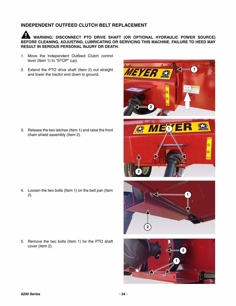
INDEPENDENT OUTFEED CLUTCH BELT REPLACEMENT
WARNING: DISCONNECT PTO DRIVE SHAFT (OR OPTIONAL HYDRAULIC POWER SOURCE)BEFORE CLEANING, ADJUSTING, LUBRICATING OR SERVICING THIS MACHINE. FAILURE TO HEED MAYRESULT IN SERIOUS PERSONAL INJURY OR DEATH.
1. Move the Independent Outfeed Clutch controllever (Item 1) to “STOP” (up).
2. Extend the PTO drive shaft (Item 2) out straightand lower the tractor end down to ground.
3. Release the two latches (Item 1) and raise the frontchain shield assembly (Item 2).
4. Loosen the two bolts (Item 1) on the belt pan (Item2).
5. Remove the two bolts (Item 1) for the PTO shaftcover (Item 2).
1
2
2
1
2
1
2
1
6200 Series - 34 -

6. Roll off the old Double V-Belt from the two pulleys.
7. Slide the old Double V-Belt under the PTO shaftcover and down over the end of the PTO driveshaft.
8. Install new Double V-Belt over the end of the PTOdrive shaft and up, under the PTO shaft cover andonto the two pulleys.
9. Move the Independent Outfeed Clutch controllever (Item 1) to “RUN” (down). Check for propertension. Adjust as needed. (See IndependentOutfeed Clutch Adjustment).
10. Refasten the PTO input shaft cover and belt pan.
11. Lower the front chain shield assembly and securethe two latches.
12. Raise the PTO drive shaft and place into the PTOstorage bracket.
INDEPENDENT OUTFEED CLUTCH ADJUSTMENTLengthen or shorten tightener rod with jam nuts to create moderate tension on the Double V-Belt when engagingthe Independent Outfeed Clutch control lever into the “Run” position. See the following illustration for componentlocations.
1
Tightener Rod
PTO Shaft Cover
Belt Pan
Offset Sleeve (if equipped)
Adjustment Nuts
Double V-Belt
6200 Series - 35 -

NOTE: Proper tension is when the belt is looseenough so that it does not engage whenthe handle is up (disengaged), and that itdoes not slip under load when the handle isdown (engaged).
1. Loosen the nut(s) on the back / front side of thehandle linkage, and then adjust the nuts on eitherside of the handle linkage.
Increase Tension - Loosen the front nut (Item 1),tighten the back nut (Item 2) to increase belt tension.When the desired tension is achieved, tighten the frontnut against the handle linkage (Item 3).
Decrease Tension - Loosen the back nut (Item 2),tighten the front nut (Item 1) against the handlelinkage (Item 3) to relieve tension on the belt. Whenthe desired tension has been removed, tighten theback nut against the handle linkage.
NOTE: The adjustment is maxed out when the rod(Item 1) hits the pivot (Item 2) whenengaging the handle.
2. (Only if Step 1 does not provide enoughadjustment.) Remove the nut(s) on the back andfront side of the handle linkage. Remove thetightener rod (Item 1), then add washers (Item 2)(as needed) to the rod behind the tightener sleeveweldment. Re-install the tightener rod. RepeatStep 1.
NOTE: If the forage box is equipped with an offsetsleeve (Item1), flip so the long end of thesleeve is toward the head of the bolt.
1 2
3
1 2
12
1
6200 Series - 36 -

This Page Intentionally Blank
6200 Series - 37 -
REPAIR PARTS
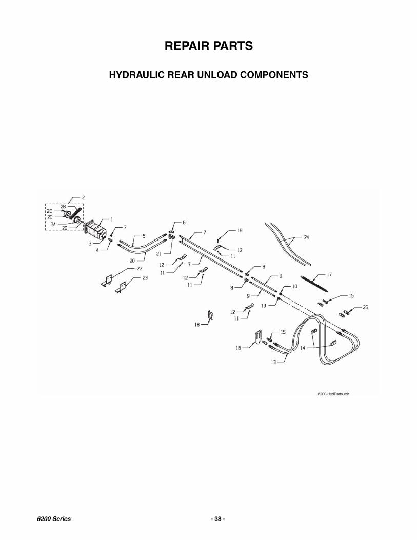
HYDRAULIC REAR UNLOAD COMPONENTS
6200 Series - 38 -
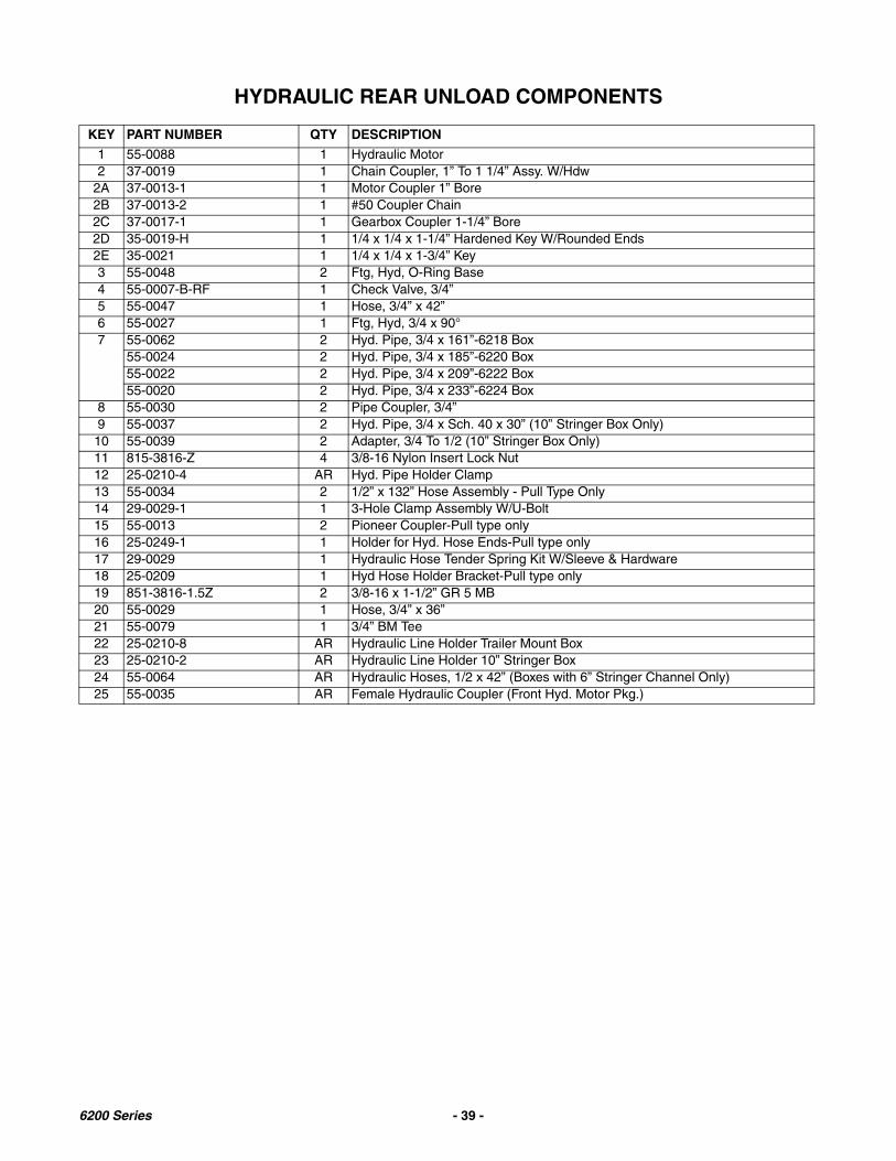
HYDRAULIC REAR UNLOAD COMPONENTS
KEY PART NUMBER QTY DESCRIPTION
1 55-0088 1 Hydraulic Motor2 37-0019 1 Chain Coupler, 1” To 1 1/4” Assy. W/Hdw
2A 37-0013-1 1 Motor Coupler 1” Bore2B 37-0013-2 1 #50 Coupler Chain2C 37-0017-1 1 Gearbox Coupler 1-1/4” Bore2D 35-0019-H 1 1/4 x 1/4 x 1-1/4” Hardened Key W/Rounded Ends2E 35-0021 1 1/4 x 1/4 x 1-3/4” Key3 55-0048 2 Ftg, Hyd, O-Ring Base4 55-0007-B-RF 1 Check Valve, 3/4”5 55-0047 1 Hose, 3/4” x 42”6 55-0027 1 Ftg, Hyd, 3/4 x 90°7 55-0062 2 Hyd. Pipe, 3/4 x 161”-6218 Box
55-0024 2 Hyd. Pipe, 3/4 x 185”-6220 Box55-0022 2 Hyd. Pipe, 3/4 x 209”-6222 Box55-0020 2 Hyd. Pipe, 3/4 x 233”-6224 Box
8 55-0030 2 Pipe Coupler, 3/4”9 55-0037 2 Hyd. Pipe, 3/4 x Sch. 40 x 30” (10” Stringer Box Only)10 55-0039 2 Adapter, 3/4 To 1/2 (10” Stringer Box Only)11 815-3816-Z 4 3/8-16 Nylon Insert Lock Nut12 25-0210-4 AR Hyd. Pipe Holder Clamp13 55-0034 2 1/2” x 132” Hose Assembly - Pull Type Only14 29-0029-1 1 3-Hole Clamp Assembly W/U-Bolt15 55-0013 2 Pioneer Coupler-Pull type only16 25-0249-1 1 Holder for Hyd. Hose Ends-Pull type only17 29-0029 1 Hydraulic Hose Tender Spring Kit W/Sleeve & Hardware18 25-0209 1 Hyd Hose Holder Bracket-Pull type only19 851-3816-1.5Z 2 3/8-16 x 1-1/2” GR 5 MB20 55-0029 1 Hose, 3/4” x 36”21 55-0079 1 3/4” BM Tee22 25-0210-8 AR Hydraulic Line Holder Trailer Mount Box23 25-0210-2 AR Hydraulic Line Holder 10” Stringer Box24 55-0064 AR Hydraulic Hoses, 1/2 x 42” (Boxes with 6” Stringer Channel Only)25 55-0035 AR Female Hydraulic Coupler (Front Hyd. Motor Pkg.)
6200 Series - 39 -

REAR UNLOAD DRIVE TRAIN
Front
Rear
6200 Series - 40 -
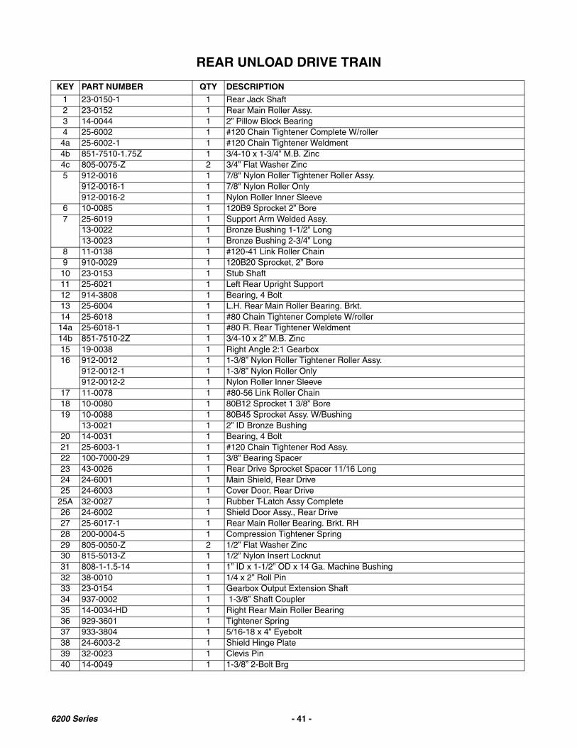
REAR UNLOAD DRIVE TRAIN
KEY PART NUMBER QTY DESCRIPTION
1 23-0150-1 1 Rear Jack Shaft2 23-0152 1 Rear Main Roller Assy.3 14-0044 1 2” Pillow Block Bearing4 25-6002 1 #120 Chain Tightener Complete W/roller4a 25-6002-1 1 #120 Chain Tightener Weldment4b 851-7510-1.75Z 1 3/4-10 x 1-3/4” M.B. Zinc4c 805-0075-Z 2 3/4” Flat Washer Zinc5 912-0016 1 7/8" Nylon Roller Tightener Roller Assy.
912-0016-1 1 7/8" Nylon Roller Only912-0016-2 1 Nylon Roller Inner Sleeve
6 10-0085 1 120B9 Sprocket 2” Bore7 25-6019 1 Support Arm Welded Assy.
13-0022 1 Bronze Bushing 1-1/2” Long13-0023 1 Bronze Bushing 2-3/4” Long
8 11-0138 1 #120-41 Link Roller Chain9 910-0029 1 120B20 Sprocket, 2” Bore10 23-0153 1 Stub Shaft11 25-6021 1 Left Rear Upright Support12 914-3808 1 Bearing, 4 Bolt13 25-6004 1 L.H. Rear Main Roller Bearing. Brkt.14 25-6018 1 #80 Chain Tightener Complete W/roller
14a 25-6018-1 1 #80 R. Rear Tightener Weldment14b 851-7510-2Z 1 3/4-10 x 2” M.B. Zinc15 19-0038 1 Right Angle 2:1 Gearbox16 912-0012 1 1-3/8” Nylon Roller Tightener Roller Assy.
912-0012-1 1 1-3/8” Nylon Roller Only912-0012-2 1 Nylon Roller Inner Sleeve
17 11-0078 1 #80-56 Link Roller Chain18 10-0080 1 80B12 Sprocket 1 3/8” Bore19 10-0088 1 80B45 Sprocket Assy. W/Bushing
13-0021 1 2” ID Bronze Bushing20 14-0031 1 Bearing, 4 Bolt21 25-6003-1 1 #120 Chain Tightener Rod Assy.22 100-7000-29 1 3/8” Bearing Spacer23 43-0026 1 Rear Drive Sprocket Spacer 11/16 Long24 24-6001 1 Main Shield, Rear Drive25 24-6003 1 Cover Door, Rear Drive
25A 32-0027 1 Rubber T-Latch Assy Complete26 24-6002 1 Shield Door Assy., Rear Drive27 25-6017-1 1 Rear Main Roller Bearing. Brkt. RH28 200-0004-5 1 Compression Tightener Spring29 805-0050-Z 2 1/2” Flat Washer Zinc30 815-5013-Z 1 1/2” Nylon Insert Locknut31 808-1-1.5-14 1 1” ID x 1-1/2” OD x 14 Ga. Machine Bushing32 38-0010 1 1/4 x 2” Roll Pin33 23-0154 1 Gearbox Output Extension Shaft34 937-0002 1 1-3/8” Shaft Coupler35 14-0034-HD 1 Right Rear Main Roller Bearing36 929-3601 1 Tightener Spring37 933-3804 1 5/16-18 x 4” Eyebolt38 24-6003-2 1 Shield Hinge Plate39 32-0023 1 Clevis Pin40 14-0049 1 1-3/8” 2-Bolt Brg
6200 Series - 41 -

OPTIONAL FRONT HYDRAULIC DRIVE
6200 Series - 42 -

OPTIONAL FRONT HYDRAULIC DRIVE
KEY PART NUMBER QTY DESCRIPTION
1 55-0099 1 Hydraulic Motor T-Series2 823-.25-5Z 2 Hitch Pin Clip, 1/4 x 5”3 25-0280-1 1 Hydraulic Clutch Bottom Bracket Brace4 25-0283 1 Stationary Hydraulic Motor Bracket Assy.5 55-0034 2 1/2" X 132” Hose Assembly (Pull Type Only)6 32-0022 2 Lanyard7 35-0012 1 1/4 x 1-1/2” Square Key8 37-0012 1 Stationary Hydraulic Motor Coupler-Welded (Prior to 07 Serial #)
8A 37-0013-1 1 Shaft Coupler Sprocket-1” Bore (Serial # 07 & Later)8B 37-0017-1 1 Shaft Coupler Sprocket 1-1/4” Bore (Serial # 07 & Later)8C 37-0013-2 1 #50 Double Coupler Chain8D 37-0019 AR Chain Coupler Assembly Complete (Serial # 07 & Later)9 49-0027-1 1 Stationary Hydraulic Motor Belting10 55-0007-B 1 3/4” Check Valve11 55-0048 1 7/8” Straight to 3/4” NPSM Swivel Coupler12 55-0013 4 Male Hydraulic Coupler (Pull Type Only)13 55-0035 2 Female Hydraulic Coupler (Pull Type Only)14 55-0036 2 Hydraulic Coupler Dust Cap (Pull Type Only)15 55-0156 1 3/4” to 1/2” Chamfered Hydraulic Adapter16 55-0159 1 5/8” to 1/2” Straight to Pipe Male Adapter17 35-0042 1 1/4” Woodruff Key18 TSS-STAT-CCU 1 Chain Coupler Update Kit19 29-0029 1 Hydraulic Hose Tender Spring Kit W/Sleeve & Hardware20 29-0029-1 1 3-Hole Clamp Assembly W/U-Bolt
6200 Series - 43 -
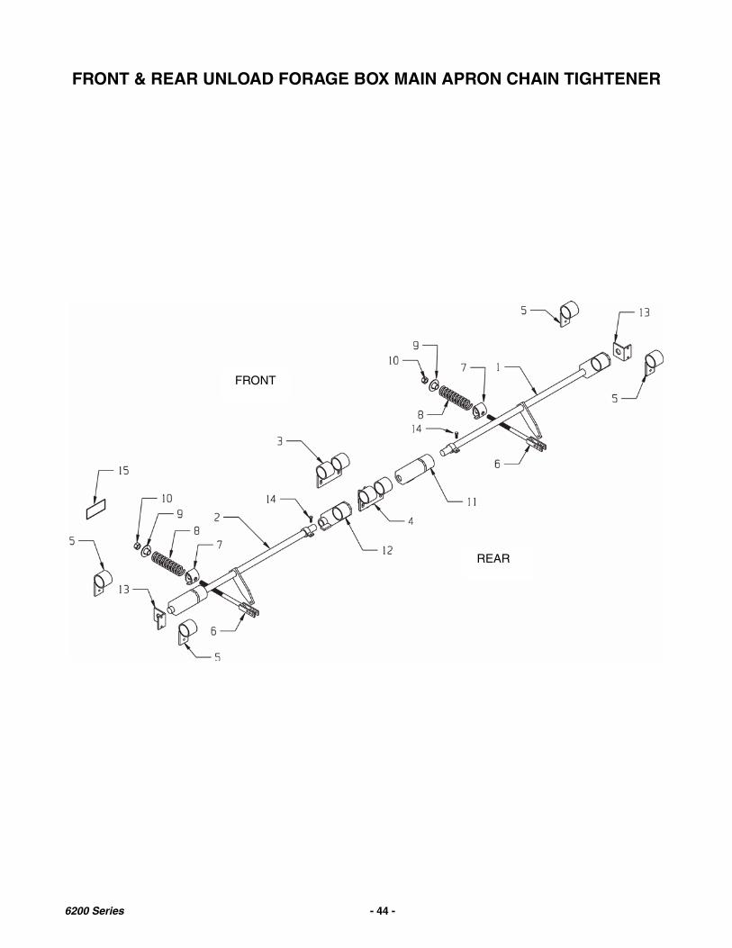
FRONT & REAR UNLOAD FORAGE BOX MAIN APRON CHAIN TIGHTENER
FRONT
REAR
6200 Series - 44 -

FRONT & REAR UNLOAD FORAGE BOX MAIN APRON CHAIN TIGHTENER
KEY PART NUMBER QTY DESCRIPTION
1 25-6010 1 Tightener Assy., R Main Apron 42” Stringers25-6010-TRUCK 1 Tightener Assy., R Main Apron 33-1/2” Stringers
2 25-6009 1 Tightener Assy., L Main Apron 42” Stringers25-6009-TRUCK 1 Tightener Assy., L Main Apron 33-1/2” Stringers
3 25-6012 1 Center Lift Pipe Assy., Main Apron4 25-6013 1 Center Lift Pipe Assy., Main Apron5 25-6008 1 Outside Lift Pipe, Main Apron Chain6 25-6007 2 Tightener Rod Assy., Main Apron7 25-6011 2 Rocking Sleeve Assy., Tightener Bolt8 929-0002 2 Main Apron Tightener Spring9 925-3841 2 Outer Spring Guide, Tightener Assy.10 815-7510-Z 2 Nut11 25-6024 2 Adjustable Tightener Arm RH12 25-6023 1 Adjustable Tightener Arm, LH13 25-0215 2 Tightener Mount Angle14 851-5013-1.25Z 2 1/2-13 x 1 1/4” Gr5 Bolt (Fine Adjustment Bolt)15 46-0001-86 2 Decal, Instruction
6200 Series - 45 -
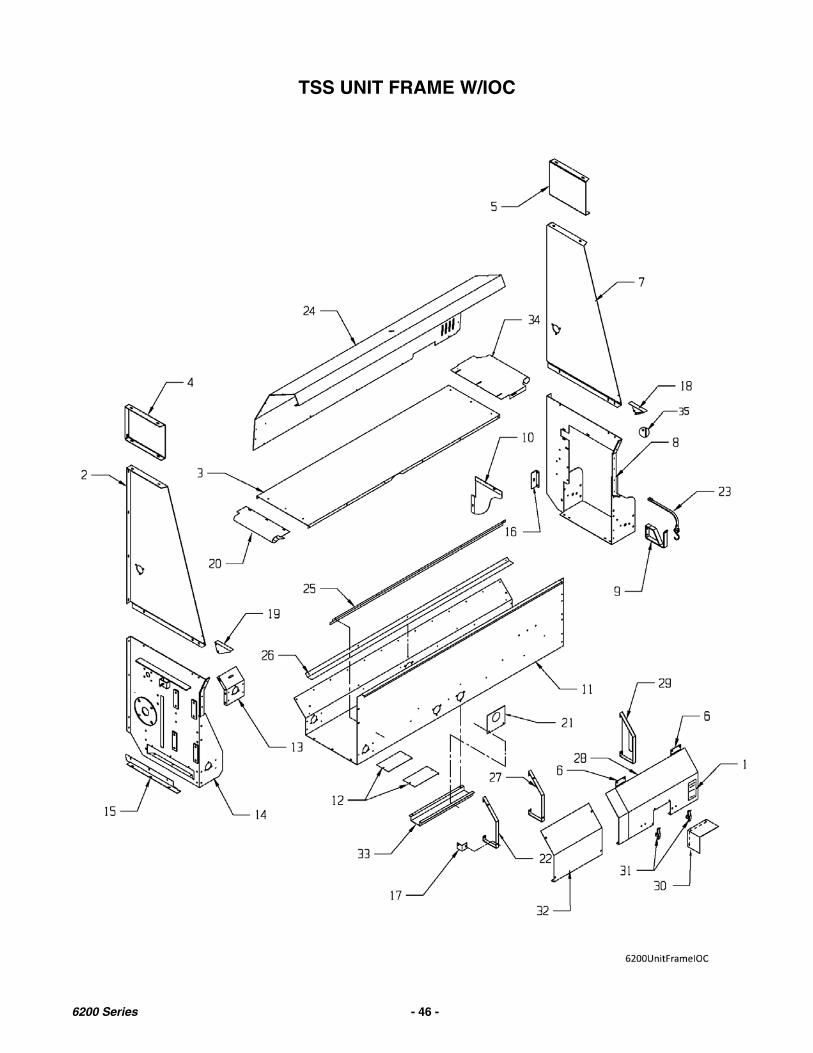
TSS UNIT FRAME W/IOC
6200 Series - 46 -
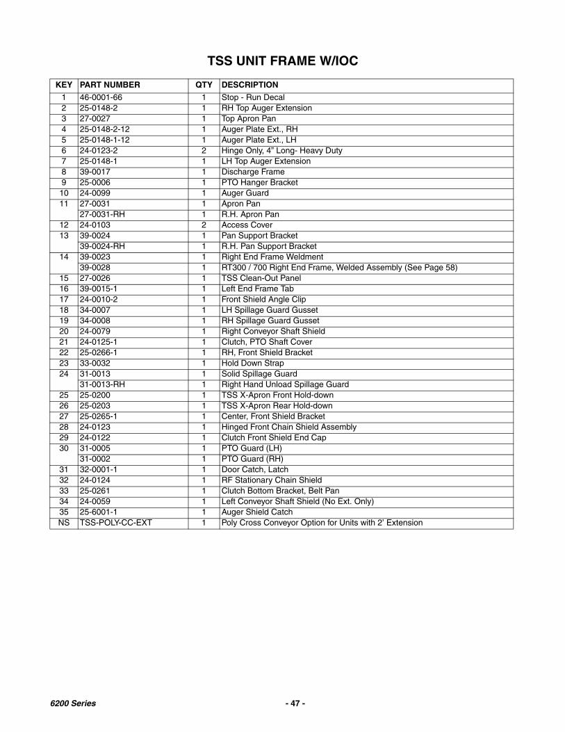
TSS UNIT FRAME W/IOC
KEY PART NUMBER QTY DESCRIPTION
1 46-0001-66 1 Stop - Run Decal2 25-0148-2 1 RH Top Auger Extension3 27-0027 1 Top Apron Pan4 25-0148-2-12 1 Auger Plate Ext., RH5 25-0148-1-12 1 Auger Plate Ext., LH6 24-0123-2 2 Hinge Only, 4” Long- Heavy Duty7 25-0148-1 1 LH Top Auger Extension8 39-0017 1 Discharge Frame9 25-0006 1 PTO Hanger Bracket10 24-0099 1 Auger Guard11 27-0031 1 Apron Pan
27-0031-RH 1 R.H. Apron Pan12 24-0103 2 Access Cover13 39-0024 1 Pan Support Bracket
39-0024-RH 1 R.H. Pan Support Bracket14 39-0023 1 Right End Frame Weldment
39-0028 1 RT300 / 700 Right End Frame, Welded Assembly (See Page 58)15 27-0026 1 TSS Clean-Out Panel16 39-0015-1 1 Left End Frame Tab17 24-0010-2 1 Front Shield Angle Clip18 34-0007 1 LH Spillage Guard Gusset19 34-0008 1 RH Spillage Guard Gusset20 24-0079 1 Right Conveyor Shaft Shield21 24-0125-1 1 Clutch, PTO Shaft Cover22 25-0266-1 1 RH, Front Shield Bracket23 33-0032 1 Hold Down Strap24 31-0013 1 Solid Spillage Guard
31-0013-RH 1 Right Hand Unload Spillage Guard25 25-0200 1 TSS X-Apron Front Hold-down26 25-0203 1 TSS X-Apron Rear Hold-down27 25-0265-1 1 Center, Front Shield Bracket28 24-0123 1 Hinged Front Chain Shield Assembly29 24-0122 1 Clutch Front Shield End Cap30 31-0005 1 PTO Guard (LH)
31-0002 1 PTO Guard (RH)31 32-0001-1 1 Door Catch, Latch32 24-0124 1 RF Stationary Chain Shield33 25-0261 1 Clutch Bottom Bracket, Belt Pan34 24-0059 1 Left Conveyor Shaft Shield (No Ext. Only)35 25-6001-1 1 Auger Shield CatchNS TSS-POLY-CC-EXT 1 Poly Cross Conveyor Option for Units with 2’ Extension
6200 Series - 47 -
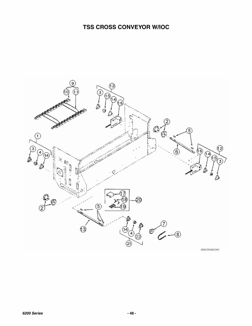
TSS CROSS CONVEYOR W/IOC
6200 Series - 48 -

TSS CROSS CONVEYOR W/IOC
KEY PART NUMBER QTY DESCRIPTION
1 14-0004 1 Bearing Assembly, 1” w/90 Degree Grease Fitting
2 10-0008 4 Sprocket, No.55-8 Tooth
3 14-0057-1 3 3 Hole Flange w/ Straight Grease Fitting for 1” Bearing
4 14-0004-3-BTS 2 Bearing, 1” B-Type Seal w/collar
5 35-0002 5 Key, Woodruff, 1/4” x 1-1/4”
6 23-0023 1 Shaft, Cross Conveyor (Left)
7 10-0007 1 Sprocket, 50B28, 1” Bore
8 11-0140 1 Roller Chain - #50 (142 links)
9 11-0059-D 1 Extension Length Cross Apron Pintle Chain Assembly Complete
11-0060-D 1 Regular Length Cross Apron Pintle Chain Assembly Complete
10 11-0006-1 264 Link, Pintle Chain (W/2 pins & cotter pins)
11 11-0006-2 19 Chain Slat w/attachments
12 14-0022 2 Tightener Bearing Assy.
13 23-0008 1 Cross Conveyor Shaft (Right)
14 14-0058-1 4 3 Hole Flange w/ No Zerk for 1” Bearing
15 14-0004-3-BTS 2 Bearing, 1” B-Type Seal w/Collar
16 25-0074 2 Bracket, Tightener Bearing
17 25-0011 1 Bracket, Chain Tightener
18 29-0002 2 Spring, Chain Tightener
19 41-0001 1 Tightener 5”, Nylon Slide
20 41-0024 1 Tightener Assy.
21 14-0004 1 Bearing Assembly, 1” w/90 Degree Grease Fitting
22 14-0059-1 1 3 Hole Flange w/ 90 Degree Grease Fitting for 1” Bearing
6200 Series - 49 -

FRONT & REAR UNLOAD MAIN APRON
6200 Series - 50 -

FRONT & REAR UNLOAD MAIN APRON
KEY PART NUMBER QTY DESCRIPTION
1 25-0237 3 Rear Apron Shield Brace2 25-6017-1 1 Right Main Roller Bracket3 25-6004 1 Left Main Roller Bracket4 25-6022-1 2 Bearing Bracket Brace5 23-0152 1 Rear Drive Main Roller6 11-0105 2 Chain Assy. 6218 Floor. 667X
11-0106 2 Chain Assy. 6220 Floor, 667X11-0119 2 Chain Assy. 6222 Floor, 667X11-0141 2 Chain Assy. 6224 Floor, 667X
7 11-0008-1 Pintle Chain Link-D667X7A 11-0008-8 Pintle Chain Pin 667X8 11-0008-2 Rivet, 3/8 x 19 11-0080 Main Apron Slat Only10 11-0008-3 Attachment Link-D667X11 24-0129 1 Rear Shield Complete12 11-0084-2 Chain Slat w/attachments-667X13 14-0050 1 Shaft Bearing Assy., Front Drive14 23-0151-1 1 Front Drive Main Drive Shaft15 19-0161 1 Front Gear Reducer (50:1)16 33-0017 2 Bolt, 5/8 x 3 1/2” Gr5 w/ Lock Nut17 823-0004 2 Snap Pin18 37-0015 1 Splined Drive Plate Assy. W/Bolts19 933-3606 1 Bronze Washer20 831-7516-2 2 Drive Bolt, 3/4-16 x 2 Allen Head Gr. 821 35-0024 4 1/2 x 1/2 x 2-1/2” Square Key22 844-7516-Z 2 3/4-16 Flange Top Locknut23 14-0038 1 T300 Front Center Main Drive Bearing24 Shim AR Center Bearing Bracket Shim25 14-0034-HD 1 Rear Main Roller Shaft Bearing Assy.26 30-0009 1 1/8” NPT Coupler27 32-0024 1 9/32” Loom Clamp28 30-0002 1 1/8” NPT Straight Zerk29 33-1003 1 Rubber Grommet30 735-.25CT Copper Tube Grease Line (By the foot)31 930-3602 2 Male Brass Compression Fitting32 10-0094-F 4 Sprocket Assy., Front Main Drive33 27-0032 2 Reverse Chain Guide Panel34 25-6016 1 Washer Assy., Front Drive35 14-0055-S 1 Split Center Bearing36 30-0018 1 1/8 x 1/8 45 Degree Straight Elbow37 933-3637 1 51” Grease Line Assembly
6200 Series - 51 -
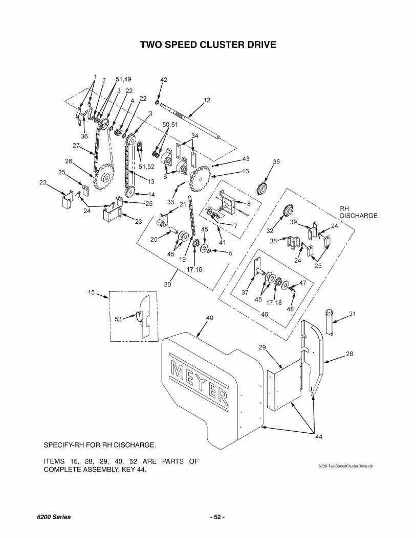
TWO SPEED CLUSTER DRIVE
SPECIFY-RH FOR RH DISCHARGE.
ITEMS 15, 28, 29, 40, 52 ARE PARTS OFCOMPLETE ASSEMBLY, KEY 44.
6200 Series - 52 -

TWO SPEED CLUSTER DRIVE
KEY PART NUMBER QTY DESCRIPTION
1 17-0001 2 Clutch Shifter Yoke2 33-0012 1 1-1/4 Dia Retaining Ring3 10-0006 2 Clutch Sprocket 50C16 1-1/4 Bore4 15-0001 1 Jaw Clutch 1-1/4 Splined Bore5 33-1000 1 1-1/8” Retaining Ring6 14-0032 4 1-1/4 Pillow Block Bearing
14-0002-3G 1-1/4 Bearing Only (Greaseable)7 10-0068 1 Idler Sprocket 50C17 w/Bearing
10-0068-1 1/2” Idler Bearing Only8 25-0165 1 Idler Sprocket Mounting Brkt12 19-0015-1-2SP 1 Upper Gearbox Input Shaft, Drilled13 11-0016 1 #50-75 Roller Chain14 10-0093 Sprocket 50B24 1-1/4” Bore 5/16” Keyway15 25-6015 1 Door Catch Assembly16 10-0072 1 Sprocket 50C28 1-1/4” Bore, Drilled17 14-0026 1 1-1/8” B Needle Bearing Only18 10-0061 1 Idler Sprocket 50C17 w/Needle Bearing19 11-0100 1 #50-195 Roller Chain20 23-0044 1 Idler Shaft21 25-0164 1 Idler Bracket Weldment22 33-0018 2 1-1/4” Snap Ring23 25-0161-1 2 Chain Tensioner Bracket24 29-0002 4 Tensioner Spring25 41-0001 2 Tightener, 5” Nylon Slide26 10-0058 1 Sprocket 50B42 1-1/4 Bore27 11-0030 1 #50-85 Roller Chain28 25-6014 1 Shield Mount Plate29 24-0112-4 1 Shield Support with Hinge30 44-0048 1 2-Spd Front Idler Shaft Assy.31 33-0044 1 Manual Holder w/Caps32 10-0004 1 Lower Shaft Sprocket, 50B17 1 1/4” Bore, 1/4” Keyway33 851-3118-3.5Z 2 5/16 x 3-1/2 MB GR534 43-0013-.5 2 Spacer Plate35 10-0019 1 Sprocket 50B22 1” Bore36 21-0001 1 Collar, Clutch Shifter-Brass37* 25-0189 1 2-Spd Idler Brkt Plate & Shaft Weldment38* 25-0183-RHH 1 Tightener Bracket Weldment (High)39* 25-0183-RHL 1 Tightener Bracket Weldment (Low)40 24-0112-1 1 Plastic Door Only41 44-0049 1 2 Spd Idler Brkt Assy. w/Sprocket42 19-0055-4-19 1 1” ID Snap Ring43 815-3118-Z 2 5/16” Nylon Insert Lock Nut44 24-0116-K 1 T300 Unit Shield Assembly45 808-1.13-1.75-18 A/R 18 Ga. 1-1/8 ID Machine Bushing46* 44-0050 1 RH 2 Spd Idler Plate Assy. w/Sprocket47 33-0030-RH 1 Idler Shaft Grease Bolt, 1/2” x 3/448 30-0004 1 1/4”-28 90° Grease Fitting49 808-1.25-1.88-18 A/R 18 Ga. 1-1/4 ID Machine Bushing50 808-1.25-1.875-10 A/R 10 Ga. 1-1/4 ID Machine Bushing51 808-1.25-1.875-14 A/R 14 Ga. 1-1/4 ID Machine Bushing52 823-0003 1 Lynch Pin
* These items for RH discharge units only
6200 Series - 53 -

TSS VARIABLE SPEED CLUSTER DRIVE W/IOC
6200 Series - 54 -
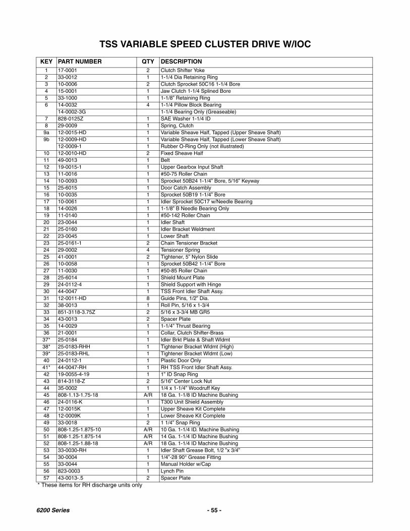
TSS VARIABLE SPEED CLUSTER DRIVE W/IOC
KEY PART NUMBER QTY DESCRIPTION1 17-0001 2 Clutch Shifter Yoke2 33-0012 1 1-1/4 Dia Retaining Ring3 10-0006 2 Clutch Sprocket 50C16 1-1/4 Bore4 15-0001 1 Jaw Clutch 1-1/4 Splined Bore5 33-1000 1 1-1/8” Retaining Ring6 14-0032 4 1-1/4 Pillow Block Bearing
14-0002-3G 1-1/4 Bearing Only (Greaseable)7 828-0125Z 1 SAE Washer 1-1/4 ID8 29-0009 1 Spring, Clutch9a 12-0015-HD 1 Variable Sheave Half, Tapped (Upper Sheave Shaft)9b 12-0009-HD 1 Variable Sheave Half, Tapped (Lower Sheave Shaft)
12-0009-1 1 Rubber O-Ring Only (not illustrated)10 12-0010-HD 2 Fixed Sheave Half11 49-0013 1 Belt12 19-0015-1 1 Upper Gearbox Input Shaft13 11-0016 1 #50-75 Roller Chain14 10-0093 1 Sprocket 50B24 1-1/4” Bore, 5/16” Keyway15 25-6015 1 Door Catch Assembly16 10-0035 1 Sprocket 50B19 1-1/4” Bore17 10-0061 1 Idler Sprocket 50C17 w/Needle Bearing18 14-0026 1 1-1/8” B Needle Bearing Only19 11-0140 1 #50-142 Roller Chain20 23-0044 1 Idler Shaft21 25-0160 1 Idler Bracket Weldment22 23-0045 1 Lower Shaft23 25-0161-1 2 Chain Tensioner Bracket24 29-0002 4 Tensioner Spring25 41-0001 2 Tightener, 5” Nylon Slide26 10-0058 1 Sprocket 50B42 1-1/4” Bore27 11-0030 1 #50-85 Roller Chain28 25-6014 1 Shield Mount Plate29 24-0112-4 1 Shield Support with Hinge30 44-0047 1 TSS Front Idler Shaft Assy.31 12-0011-HD 8 Guide Pins, 1/2” Dia.32 38-0013 1 Roll Pin, 5/16 x 1-3/433 851-3118-3.75Z 2 5/16 x 3-3/4 MB GR534 43-0013 2 Spacer Plate35 14-0029 1 1-1/4” Thrust Bearing36 21-0001 1 Collar, Clutch Shifter-Brass37* 25-0184 1 Idler Brkt Plate & Shaft Wldmt38* 25-0183-RHH 1 Tightener Bracket Wldmt (High)39* 25-0183-RHL 1 Tightener Bracket Wldmt (Low)40 24-0112-1 1 Plastic Door Only41* 44-0047-RH 1 RH TSS Front Idler Shaft Assy.42 19-0055-4-19 1 1” ID Snap Ring43 814-3118-Z 2 5/16” Center Lock Nut44 35-0002 1 1/4 x 1-1/4” Woodruff Key45 808-1.13-1.75-18 A/R 18 Ga. 1-1/8 ID Machine Bushing46 24-0116-K 1 T300 Unit Shield Assembly47 12-0015K 1 Upper Sheave Kit Complete48 12-0009K 1 Lower Sheave Kit Complete49 33-0018 2 1 1/4” Snap Ring50 808-1.25-1.875-10 A/R 10 Ga. 1-1/4 ID. Machine Bushing51 808-1.25-1.875-14 A/R 14 Ga. 1-1/4 ID Machine Bushing52 808-1.25-1.88-18 A/R 18 Ga. 1-1/4 ID Machine Bushing53 33-0030-RH 1 Idler Shaft Grease Bolt, 1/2 ”x 3/4”54 30-0004 1 1/4”-28 90° Grease Fitting55 33-0044 1 Manual Holder w/Cap56 823-0003 1 Lynch Pin57 43-0013-.5 2 Spacer Plate
* These items for RH discharge units only
6200 Series - 55 -

RT160 VARIABLE SPEED CLUSTER DRIVE W/IOC
6200 Series - 56 -

RT160 VARIABLE SPEED CLUSTER DRIVE W/IOC
KEY PART NUMBER QTY DESCRIPTION
1 17-0001 2 Clutch Shifter Yoke2 33-0012 1 1-1/4” Diameter Retaining Ring3 10-0006 2 Clutch Sprocket 50C16 1-1/4” Bore4 15-0001 1 Jaw Clutch 1-1/4” Splined Bore5 33-1000 1 1-1/8” Retaining Ring6 14-0032 4 1-1/4” Pillow Block Bearing
14-0032-3G 1-1/4” Bearing Only (Greaseable)7 828-0125Z 2 SAE Washer 1-1/4” ID8 29-0009 1 Spring, Clutch9a 12-0015-HD 1 Variable Sheave Half, Tapped (Upper Sheave Shaft)9b 12-0009-HD 1 Variable Sheave Half, Tapped (Lower Sheave Shaft)
12-0009-1 1 Rubber O-Ring Only (Not Illustrated)10 12-0010-HD 2 Fixed Sheave Half11 49-0013 1 Belt12 23-0167 1 RT160 Upper Gearbox Input Shaft13 11-0057 1 #50-71 Roller Chain14 10-0093 1 Sprocket 50B24 1-1/4” Bore, 5/16” Keyway15 25-6015 1 Door Catch Assembly16 10-0035 1 Sprocket 50B19 1-1/4” Bore17 10-0061 1 Idler Sprocket 50C17 W/Needle Bearing18 14-0026 1 1-1/8” Bore Needle Bearing Only19 11-0140 1 #50-142 Roller Chain20 23-0044 1 Idler Shaft21 25-0160 1 Idler Bracket Weldment22 23-0045 1 Lower Shaft23 25-0423 2 RT160 Chain Tensioner Bracket24 29-0002 4 Tensioner Spring25 41-0001 2 Tightener, 5” Nylon Slide26 10-0058 1 Sprocket 50B42 1-1/4” Bore27 111-0050-81 1 #50-81 Roller Chain28 25-6014 1 Shield Mount Plate29 24-0112-4 1 Shield Support With Hinge30 44-0047 1 TSS Front Idler Shaft Assembly31 12-0011-HD 8 Guide Pins, 1/2” Diameter32 38-0013 1 Roll Pin, 5/16 x 1-3/4”33 851-3118-3.75Z 2 5/16 x 3-3/4” Bolt
6200 Series - 57 -
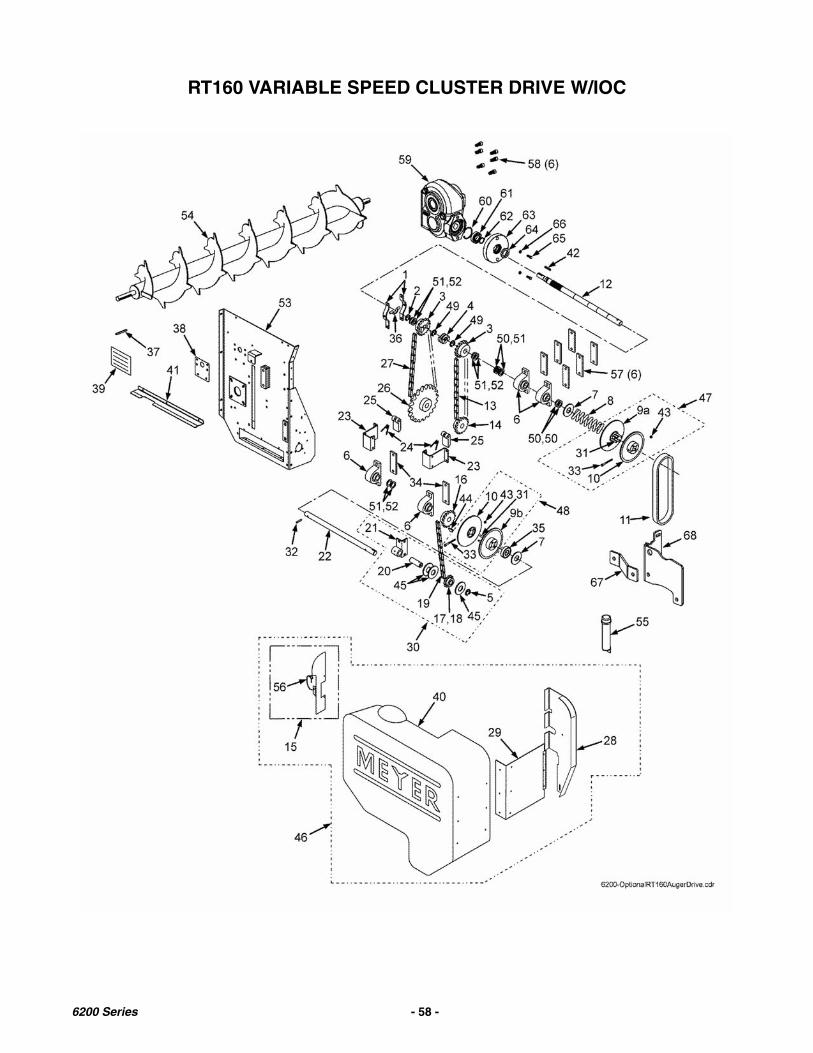
RT160 VARIABLE SPEED CLUSTER DRIVE W/IOC
6200 Series - 58 -
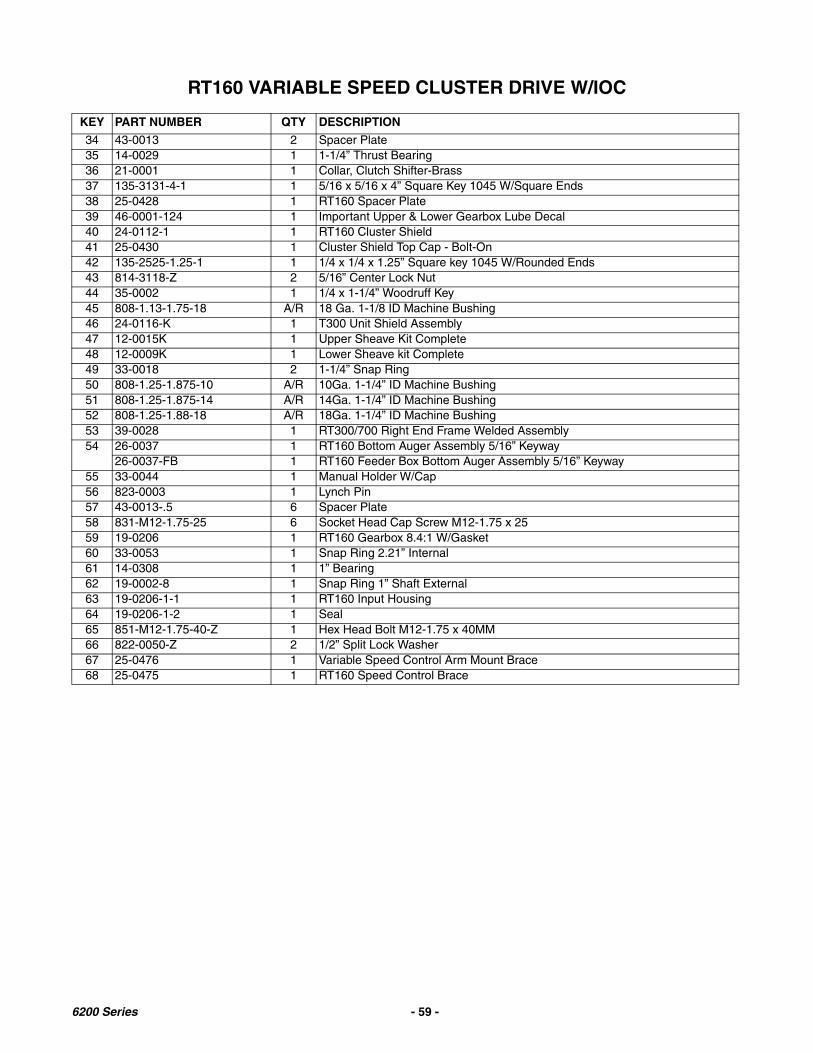
RT160 VARIABLE SPEED CLUSTER DRIVE W/IOC
KEY PART NUMBER QTY DESCRIPTION
34 43-0013 2 Spacer Plate35 14-0029 1 1-1/4” Thrust Bearing36 21-0001 1 Collar, Clutch Shifter-Brass37 135-3131-4-1 1 5/16 x 5/16 x 4” Square Key 1045 W/Square Ends38 25-0428 1 RT160 Spacer Plate39 46-0001-124 1 Important Upper & Lower Gearbox Lube Decal40 24-0112-1 1 RT160 Cluster Shield41 25-0430 1 Cluster Shield Top Cap - Bolt-On42 135-2525-1.25-1 1 1/4 x 1/4 x 1.25” Square key 1045 W/Rounded Ends43 814-3118-Z 2 5/16” Center Lock Nut44 35-0002 1 1/4 x 1-1/4” Woodruff Key45 808-1.13-1.75-18 A/R 18 Ga. 1-1/8 ID Machine Bushing46 24-0116-K 1 T300 Unit Shield Assembly47 12-0015K 1 Upper Sheave Kit Complete48 12-0009K 1 Lower Sheave kit Complete49 33-0018 2 1-1/4” Snap Ring50 808-1.25-1.875-10 A/R 10Ga. 1-1/4” ID Machine Bushing51 808-1.25-1.875-14 A/R 14Ga. 1-1/4” ID Machine Bushing52 808-1.25-1.88-18 A/R 18Ga. 1-1/4” ID Machine Bushing53 39-0028 1 RT300/700 Right End Frame Welded Assembly54 26-0037 1 RT160 Bottom Auger Assembly 5/16” Keyway
26-0037-FB 1 RT160 Feeder Box Bottom Auger Assembly 5/16” Keyway55 33-0044 1 Manual Holder W/Cap56 823-0003 1 Lynch Pin57 43-0013-.5 6 Spacer Plate58 831-M12-1.75-25 6 Socket Head Cap Screw M12-1.75 x 2559 19-0206 1 RT160 Gearbox 8.4:1 W/Gasket60 33-0053 1 Snap Ring 2.21” Internal61 14-0308 1 1” Bearing62 19-0002-8 1 Snap Ring 1” Shaft External63 19-0206-1-1 1 RT160 Input Housing64 19-0206-1-2 1 Seal65 851-M12-1.75-40-Z 1 Hex Head Bolt M12-1.75 x 40MM66 822-0050-Z 2 1/2” Split Lock Washer67 25-0476 1 Variable Speed Control Arm Mount Brace68 25-0475 1 RT160 Speed Control Brace
6200 Series - 59 -
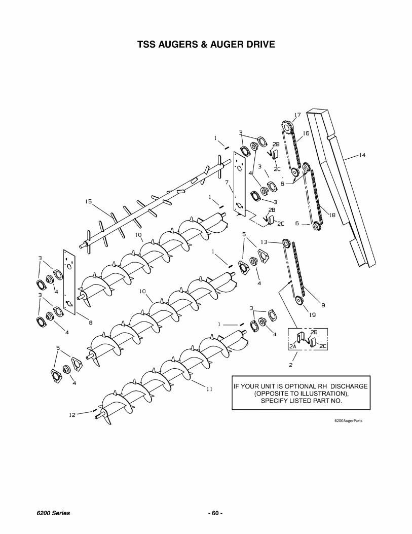
TSS AUGERS & AUGER DRIVE
6200 Series - 60 -

TSS AUGERS & AUGER DRIVE
KEY PART NUMBER QTY DESCRIPTION
1 35-0006 4 Key 3/8 x 1-1/42 41-0009 1 Lower Auger Drive Chain Tightener Assembly
2A 25-0047 1 Mounting Bracket2B 29-0002 2 Spring2C 41-0002 1 Tightener, 3” Nylon Slide3 14-0003-2 10 1-1/4 Bearing Flange, 2 Hole4 14-0002-3 7 Bearing w/Collar 1-1/45 14-0002-2 4 1-1/4 Bearing Flange, 3 Hole6 10-0012 3 Sprocket 50B17, 1-1/4 Bore, 3/8” Keyway7 25-6025 1 Top Auger Mounting Bracket w/Tightener Bracket8 100-9990-200-1-1 1 Right Top Auger Mounting Bracket9 11-0079 1 Lower Auger #60-80 Roller Chain (Prior to Serial #11T3223)
111-0060-83 1 Lower Auger #60-83 Roller Chain (Serial #11T3223 & Later)10 26-0034 2 Auger 2nd & 3rd
26-0034-FB 1 Feeder Box Models - 2nd Auger11 26-0033 1 Lower Auger 1/4” Key (Prior to serial #09T3201)
26-0033-FB 1 Feeder Box Lower Auger 1/4” Key (Feeder Box Models: Prior To Serial #09T5201, 09T6201)
26-0036 1 Lower Auger 5/16"Key (Serial #09T3201 & Later)26-0036-FB 1 Feeder Box Lower Auger 5/16” Key (Feeder Box Models: Serial #09T5201,
09T6201 & Later)26-0037-FB RT160 Feeder Box Bottom Auger Assembly 5/16” Keyway (See Page 58)
12 35-0028 1 Key 1/4 x 1-1/4” (Prior to serial #09T3201)35-0030-H 1 Key 5/16 x 1-1/4” Hardened (Serial #09T3201 Thru 11T3222)135-31W-1.25-1 1 Woodruff Key 5/16” x 1-1/4” Hardened (Serial #11T3223 & Later)
13 10-0095 1 60B15 Sprocket, 1-1/4” Bore, 3/8” Keyway14 24-6004 1 Auger Shield Welded Assy.
14A 24-0123-2 3 Hinges Only15 26-0035 1 Upper Auger 4th16 11-0139 1 3rd-4th Auger Chain #50-89 Link17 10-0009 1 50B36 Sprocket, 1-1/4” Bore, 3/8” Keyway18 11-0074 1 2nd-3rd Auger Chain #50-9419 10-0095 1 60B15 Sprocket, 1-1/4” Bore, 3/8” Keyway (Prior to Serial #11T3223)
110-60B20-1.25-1 1 60B20 Sprocket, 1-1/4” Bore, 3/8” Keyway (Serial #11T3223 & Later)
6200 Series - 61 -

INDEPENDENT OUTFEED CLUTCH DRIVE
“STOP” & “RUN” CONTROL RELATED PARTS
6200 Series - 62 -

INDEPENDENT OUTFEED CLUTCH DRIVE
KEY PART NUMBER QTY DESCRIPTION
1 23-0081 1 Clutch Drive Idler Shaft2 35-0016 1 1/4” x 1/4” x 2-1/4” Key3 23-0082 1 2-Way Unit Center Shaft4 35-0001 1 1/4” x 1/4” x 1-1/8” Key5 25-0267 1 Clutch Plate Weldment w/Jam Nut6 14-0002-2 8 Flange, 3 Hole, 1-1/4”7 14-0002-3 4 Bearing, 1-1/4” w/Collar8 14-0002 4 Bearing Assembly, 1-1/4”9 814-3816-Z 1 3/8” -16 Indented Lock Nut10 933-3621 1 3/4” -10 Jam Nut11 25-0260-4 1 Clutch Tightener Arm Weldment12 912-0002-1 1 Tightener Roller 2” (Rubber)13 805-0038-Z 2 3/8” Flat Washer14 813-3816-Z 1 3/8” -16 Regular Nut15 826-1014 1 1”-14 Jam Nut (only)16 49-0023 1 Clutch, Double V-Belt17 12-0020 2 8” Double Pulley, 1-1/4 ” B, 1/4” KWY18 16-0041 1 Linkage Pivot Sleeve Weldment19 801-3816-17.5 1 3/8” -16 x 17-1/2” HHCS20 33-0020 1 Retaining Ring21 808-1-1.15-18 A/R 18 Ga. 1” ID Machine Bushing22 29-0005 1 Extension Spring23 10-0004 1 50B17 Sprocket, 1-¼”B, ¼” KWY24 811-2520-2.5Z 1 1/4” -20 x 2-1/2” Eye Bolt - Zinc25 810-2520-Z 2 1/4” -20 Flange Spin Lock Nut26 851-7510-3Z 1 3/4” -10 x 3” GR5 MB ZN27 38-0015 1 5/16” x 2” Roll Pin28 46-0001-68 1 Rear Unload Engage/Disengage Decal29 35-0021 1 1/4” x 1/4” x 1-3/4” Key30 43-0022 1 Spacer
6200 Series - 63 -
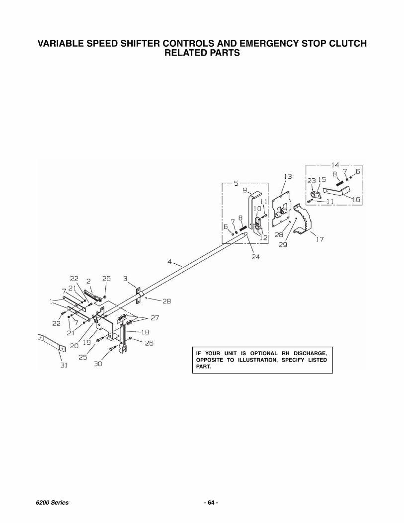
VARIABLE SPEED SHIFTER CONTROLS AND EMERGENCY STOP CLUTCHRELATED PARTS
IF YOUR UNIT IS OPTIONAL RH DISCHARGE,OPPOSITE TO ILLUSTRATION, SPECIFY LISTEDPART.
6200 Series - 64 -
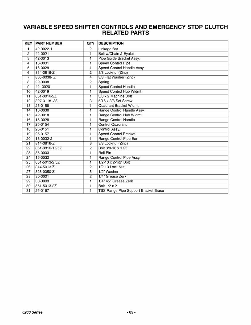
VARIABLE SPEED SHIFTER CONTROLS AND EMERGENCY STOP CLUTCHRELATED PARTS
KEY PART NUMBER QTY DESCRIPTION
1 42-0022-1 2 Linkage Bar2 42-0021 1 Bolt w/Chain & Eyelet3 42-0013 1 Pipe Guide Bracket Assy.4 16-0031 1 Speed Control Pipe5 16-0029 1 Speed Control Handle Assy.6 814-3816-Z 2 3/8 Locknut (Zinc)7 805-0038- Z 4 3/8 Flat Washer (Zinc)8 29-0008 2 Spring9 42- 0020 1 Speed Control Handle10 42-0019 1 Speed Control Hub Wldmt11 851-3816-2Z 1 3/8 x 2 Machine Bolt12 827-3118-.38 3 5/16 x 3/8 Set Screw13 25-0158 1 Quadrant Bracket Wldmt14 16-0030 1 Range Control Handle Assy.15 42-0018 1 Range Control Hub Wldmt16 16-0028 1 Range Control Handle17 25-0154 1 Control Quadrant18 25-0151 1 Control Assy.19 25-0157 1 Speed Control Bracket20 16-0032-2 1 Range Control Pipe Ear21 814-3816-Z 3 3/8 Locknut (Zinc)22 851-3816-1.25Z 2 Bolt 3/8-16 x 1.2523 38-0003 1 Roll Pin24 16-0032 1 Range Control Pipe Assy.25 851-5013-2.5Z 1 1/2-13 x 2-1/2” Bolt26 814-5013-Z 2 1/2-13 Lock Nut27 828-0050-Z 5 1/2” Washer28 30-0001 2 1/4” Grease Zerk29 30-0003 1 1/4” 45° Grease Zerk30 851-5013-2Z 1 Bolt 1/2 x 231 25-0167 1 TSS Range Pipe Support Bracket Brace
6200 Series - 65 -

INDEPENDENT OUTFEED CLUTCH
KEY PART NUMBER QTY DESCRIPTION
1 36-0001 2 Cables, Emergency Stop36-0007 4 Cable Crimp Only
2 16-0010 1 Push Bar, Emergency Stop, Control3 36-0002 1 Cable, Emergency Stop Front
36-0007 2 Cable Crimp Only4 51-0003 1 7/8” ID Rubber Grip Only5 16-0044 1 I.O.C. Handle - Weldment6 30-0001 1 1/4”-28 Straight Grease Fitting7 811-2520-1Z 1 1/4”-20x1” Eye Bolt - Zinc8 814-2520-Z 1 1/4”-20 Indented Lock Nut9 851-3816-1.5Z 1 3/8”-16x1-1/2” Machine Bolt - Zinc GR510 805-0038-Z 4 3/8” Flat Washer11 814-3816-Z 1 3/8”-16 Indented Lock Nut12 25-0268-1 1 Linkage Extension Plate13 25-0279 1 Pivot Shaft Weldment14 33-0048 2 Cable Thimble
6200 Series - 66 -

TWO SPEED HI-LO SHIFTER CONTROL
KEY PART NUMBER QTY DESCRIPTION
1 42-0022-1 2 Linkage Bar2 851-3816-1.25Z 2 Bolt 3/8-16 x 1.253 16-0032-2 1 Range Control Pipe Ear4 38-0003 1 Roll Pin 1/4 x 1-1/4”5 25-0154 1 Control Quadrant6 814-3816-Z 4 3/8 Locknut (Zinc)7 805-0038- Z 3 3/8 Flat Washer (Zinc)8 29-0008 1 Spring9 30-0001 2 1/4” Grease Zerk10 30-0003 1 1/4” 45° Grease Zerk11 851-3816-2Z 1 3/8 x 2 Machine Bolt12 25-0157 1 Speed Control Bracket13 25-0158 1 Quadrant Bracket Wldmt14 16-0030 1 Range Control Handle Assy.15 42-0018 1 Range Control Wldmt16 16-0028 1 Range Control Handle
6200 Series - 67 -

UPPER GEAR BOX WITH INPUT SHAFT ASSEMBLY10:1
USE ONLY SYNTHETIC ISO 460 GEAR OIL AGMA 7(NON EP) OR EQUIVALENT. DO NOT USE GREASEFOR LUBRICANT.
6200 Series - 68 -

UPPER GEAR BOX WITH INPUT SHAFT ASSEMBLY10:1
KEY PART NUMBER QTY DESCRIPTION
19-0158 1 Upper Gearbox w/ Input Shaft, 10:1, 5/16” Key19-0158-4 1 Upper Gearbox w/o Input Shaft, 10:1, 5/16” Key
1 19-0055-4-1 1 Tapped Gearbox Casting2 19-0055-4-2 1 Thru Hole Casting3 9-0058-GS 1 10:1 Gear Set, 4140 Gear, Bronze Worm, 5/16” Key (Prior to 12T5296,
12T6226)19-0058-4-2-4140 1 10:1 4140 Gear, 5/16” Key (SN12T5296, 12T6226 & Later)
4 19-0055-4-4 2 Bearing Cone5 19-0055-4-5 4 Bearing Cup6 19-0055-4-6 2 Bearing Cone7 19-0024-12 1 Seal 1” ID x 1 1/2” OD8 19-0016-10 1 Seal 1 1/4” ID x 2” OD9 19-0055-4-9 2 Plug, 1/4-18 NPT Plug10 19-0055-4-21 A/R Bolt 5/16-18 x 1 1/4” SHCS11 19-0058-GS 1 10:1 Gear Set, 4140 Gear, Bronze Worm, 5/16” Key (Prior to 12T5296,
12T6226)19-0058-4-3-BR 1 Bronze Rolled Worm Gear 10:1 (SN12T5296, 12T6226 & Later)
12 19-0024-28 1 End Cap 1 1/2”13 19-0024-19 1 End Cap 2 5/16”14 19-0055-4-15 1 End Cap 2”15 19-0024-27 1 Seal 1” ID x 2 5/16” OD16 19-0055-4-17 1 Bushing 1/4” NPT x 1/8” NPT17 19-0055-4-18 1 Vent Plug 5 PSI18 19-0055-4-19 1 External Retaining Ring 1.0 Shaft19 9-0055-4-20 1 11” ID Spacer20 19-0003-6 1 Woodruff Key21 19-0015-1 1 TSS Input Shaft22 35-0028 1 Key, 1/4” x 1-1/4” (Superior Split Housing) (Prior to SN 09T3201)
35-0030-H-SK 1 Key, 1/4” x 5/16” x 1-1/4” Hardened(w/Updated Gear or GearBox)(Prior to SN 09T3201)
35-0030-H 1 Key, 5/16” x 5/16” x 1-1/4” Hardened (SN 09T3201 thru 11T3222)135-31W-1.25-1 1 Key, Woodruff 5/16 x 1-1/4” Hardened (SN 11T3223 & Later)
6200 Series - 69 -

19-0206RT160 UPPER GEARBOX ASSEMBLY
USE ONLY 80W90 OIL
6200 Series - 70 -
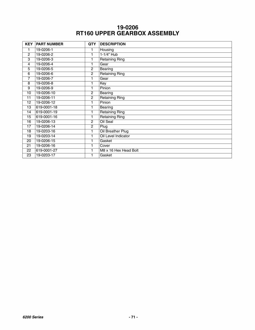
19-0206RT160 UPPER GEARBOX ASSEMBLY
KEY PART NUMBER QTY DESCRIPTION
1 19-0206-1 1 Housing2 19-0206-2 1 1-1/4” Hub3 19-0206-3 1 Retaining Ring4 19-0206-4 1 Gear5 19-0206-5 2 Bearing6 19-0206-6 2 Retaining Ring7 19-0206-7 1 Gear8 19-0206-8 1 Key9 19-0206-9 1 Pinion10 19-0206-10 2 Bearing11 19-0206-11 2 Retaining Ring12 19-0206-12 1 Pinion13 619-0001-18 1 Bearing14 619-0001-19 1 Retaining Ring15 619-0001-16 1 Retaining Ring16 19-0206-13 2 Oil Seal17 19-0206-14 2 Plug18 19-0203-16 1 Oil Breather Plug19 19-0203-14 1 Oil Level Indicator20 19-0206-15 1 Gasket21 19-0206-16 1 Cover22 619-0001-27 1 M8 x 16 Hex Head Bolt23 19-0203-17 1 Gasket
6200 Series - 71 -
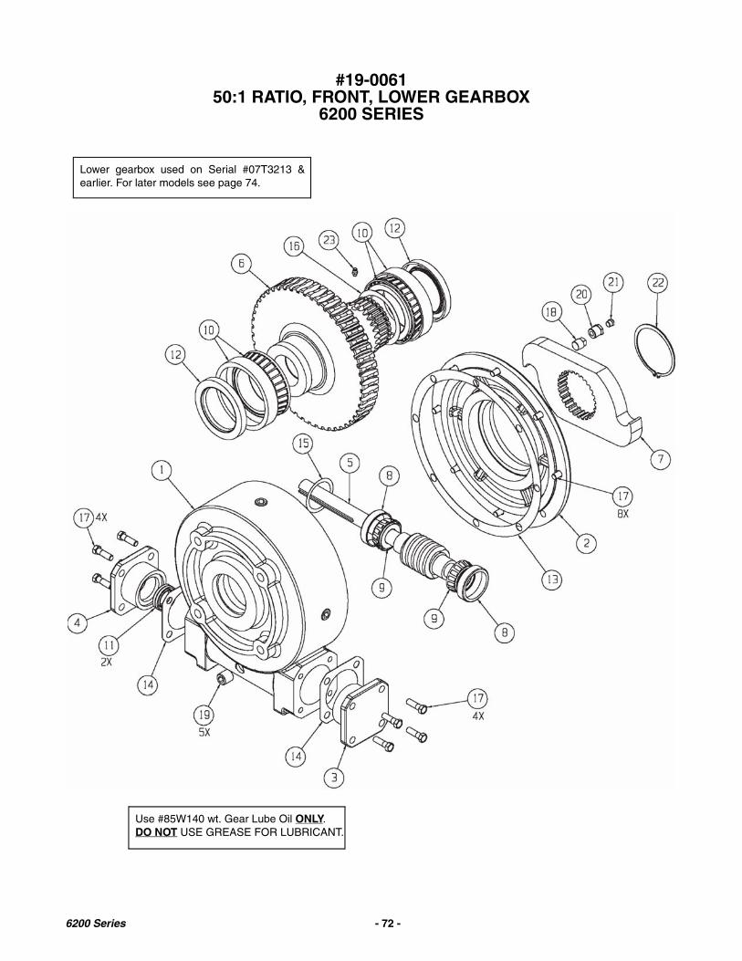
#19-006150:1 RATIO, FRONT, LOWER GEARBOX
6200 SERIES
Lower gearbox used on Serial #07T3213 &earlier. For later models see page 74.
Use #85W140 wt. Gear Lube Oil ONLY.DO NOT USE GREASE FOR LUBRICANT.
6200 Series - 72 -

#19-006150:1 RATIO, FRONT, LOWER GEARBOX
6200 SERIES
KEY PART NUMBER QTY DESCRIPTION
1 19-0061-1 1 Housing2 19-0061-2 1 Output Cover3 19-0051-3 1 End cap4 19-0051-4 1 End cap5 19-0051-5 1 Input Worm Shaft6 19-0061-3 1 Gear Wheel 27 Tooth Spline7 37-0016-1 1 Drive Plate8 19-0051-8 2 Bearing, Input Cup9 19-0051-9 2 Bearing, Input Cone10 19-0061-4 2 Bearing, Output Cup/Cone11 19-0051-12 2 Input Seal12 19-0061-5 2 Output Seal13 19-0051-16 1 Cover Gasket14 19-0051-17 2 Input Gasket15 19-0051-18 A/R Input Shim16 19-0061-6 A/R Output Shim17 851-3816-1Z 16 Bolt 3/8-16 x 1” Grade 518 19-0061-7 1 Plug, 3/8-18 NPT19 19-0061-8 5 Plug, 1/2-14 NPT20 19-0051-21 1 Bushing 1/2-14/1/8-2721 19-0057-24 1 Plug, 5 PSI22 19-0061-9 1 Retaining Ring External23 30-0022 1 Grease Zerk 1/4-2824 48-0044 88 oz. Lube, EP 85W140
6200 Series - 73 -

#19-016150:1 RATIO, FRONT, LOWER GEARBOX
6200 SERIES
Use #85W140 wt. Gear Lube Oil ONLY.DO NOT USE GREASE FOR LUBRICANT.
Lower gearbox used on Serial #07T3214 &earlier. For later models see page 72.
6200 Series - 74 -

#19-016150:1 RATIO, FRONT, LOWER GEARBOX
6200 SERIES
KEY PART NUMBER QTY DESCRIPTION
1 19-0061-1 1 Housing2 19-0061-2 1 Output Cover3 19-0051-3 1 End cap (Closed)4 19-0051-4 1 End cap (Open)5 19-0051-5 1 Input Worm & Shaft Assy6 19-0061-3 1 Gear Wheel 27 Tooth Spline7 37-0016-1 1 Drive Plate8 19-0051-8 2 Bearing, Input Cup9 19-0051-9 2 Bearing, Input Cone10 19-0061-4 2 Bearing, Output Cup/Cone11 19-0051-12 2 Input Seal12 19-0061-5 2 Output Seal13 19-0161-4 2 Bushing, Al Bronze14 19-0051-16 1 Cover Gasket15 19-0051-17 2 Input Gasket16 19-0051-18 A/R Input Shim17 19-0061-6 A/R Output Shim18 851-3816-1Z 16 Bolt 3/8-16 x 1” Grade 519 19-0061-7 1 Plug, 3/8-18 NPT20 19-0061-8 5 Plug, 1/2-14 NPT21 19-0051-21 1 Bushing 1/2-14/1/8-2722 19-0057-24 1 Plug, 5 PSI23 19-0061-9 1 Retaining Ring External24 30-0001 1 Grease Zerk 1/4-2825 48-0044 88 oz. Lube, E85W140
6200 Series - 75 -

#19-0038 2:1 RATIO GEARBOX
IMPORTANT: VERIFY CORRECT DRIVE ROTATIONBEFORE OPERATING. FAILURE TO DO SO MAYRESULT IN SEVERE EQUIPMENT DAMAGE.
Use #80-90 wt. Gear Lube Oil ONLY. DO NOTUSE GREASE FOR LUBRICANT.
KEY PART NO. DESCRIPTION1 19-0034-4 Output Shaft/Gear Assembly2 19-0018-2 Seal
3 19-0018-3 Bearing Cone
4 19-0016-3 Bearing Cup5 19-0018-4 Retaining Ring
6 19-0034-3 Input Shaft/Gear Assembly
7 19-0043-1 Gearbox Casting (Tapped Holes)8 19-0041-2 Gearbox Casting (Thru Holes)
9 19-0002-17 Vent Plug, 5 PSI
10 19-0023-2 Bushing, 1/2-14 NPT11 19-0016-5 Plug, 1/2-14 NPT
12 19-0016-11 Bolt, 3/8-16 x 1.50 SHCS
6200 Series - 76 -
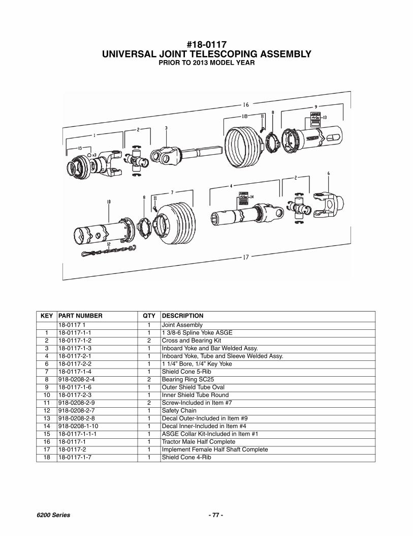
#18-0117UNIVERSAL JOINT TELESCOPING ASSEMBLY
PRIOR TO 2013 MODEL YEAR
KEY PART NUMBER QTY DESCRIPTION
18-0117 1 1 Joint Assembly1 18-0117-1-1 1 1 3/8-6 Spline Yoke ASGE2 18-0117-1-2 2 Cross and Bearing Kit3 18-0117-1-3 1 Inboard Yoke and Bar Welded Assy.4 18-0117-2-1 1 Inboard Yoke, Tube and Sleeve Welded Assy.6 18-0117-2-2 1 1 1/4” Bore, 1/4” Key Yoke7 18-0117-1-4 1 Shield Cone 5-Rib8 918-0208-2-4 2 Bearing Ring SC259 18-0117-1-6 1 Outer Shield Tube Oval10 18-0117-2-3 1 Inner Shield Tube Round11 918-0208-2-9 2 Screw-Included in Item #712 918-0208-2-7 1 Safety Chain13 918-0208-2-8 1 Decal Outer-Included in Item #914 918-0208-1-10 1 Decal Inner-Included in Item #415 18-0117-1-1-1 1 ASGE Collar Kit-Included in Item #116 18-0117-1 1 Tractor Male Half Complete17 18-0117-2 1 Implement Female Half Shaft Complete18 18-0117-1-7 1 Shield Cone 4-Rib
6200 Series - 77 -
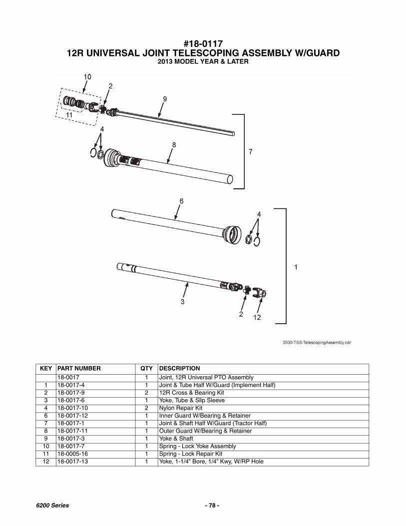
#18-011712R UNIVERSAL JOINT TELESCOPING ASSEMBLY W/GUARD
2013 MODEL YEAR & LATER
KEY PART NUMBER QTY DESCRIPTION
18-0017 1 Joint, 12R Universal PTO Assembly1 18-0017-4 1 Joint & Tube Half W/Guard (Implement Half)2 18-0017-9 2 12R Cross & Bearing Kit3 18-0017-6 1 Yoke, Tube & Slip Sleeve4 18-0017-10 2 Nylon Repair Kit6 18-0017-12 1 Inner Guard W/Bearing & Retainer7 18-0017-1 1 Joint & Shaft Half W/Guard (Tractor Half)8 18-0017-11 1 Outer Guard W/Bearing & Retainer9 18-0017-3 1 Yoke & Shaft10 18-0017-7 1 Spring - Lock Yoke Assembly11 18-0005-16 1 Spring - Lock Repair Kit12 18-0017-13 1 Yoke, 1-1/4” Bore, 1/4” Kwy, W/RP Hole
6200 Series - 78 -

STEEL STRINGER TIE DOWN KIT
KEY PART NUMBER QTY DESCRIPTION
52-0003S 1 Tie Down Kit (Steel Stringers)1 25-0084 4 Bracket2 52-0003-1 4 51” Standard Tie Down Chain
75-0341-4-HD 4 61” Heavy Duty Tie Down Chain for Riser Option3 851-3816-1.5Z 4 Bolt, Hex Machine-3/8 x 1-1/24 805-0038-Z 8 3/8 Flat Washer5 815-3816-Z 4 3/8 Lock Nut6 851-5013-1.5-Z 8 1/2 x 1-1/2 Hex Machine Bolt7 805-0050-Z 8 1/2 Flat Washers8 815-5013-Z 8 1/2 Lock Nuts
6200 Series - 79 -

#52-0001TK TSS 12" OPTIONAL EXTENSION KIT(Regular LH Unloading)
#52-0021 OPTIONAL HYDRAULIC LIFT PKG(Not Shown)
#52-0009K-FB CROSS CONVEYOR EXTENSION KIT
6200 Series - 80 -

#52-0001TK TSS 12" OPTIONAL EXTENSION KIT(Regular LH Unloading)
#52-0021 OPTIONAL HYDRAULIC LIFT PKG(Not Shown)
#52-0009K-FB CROSS CONVEYOR EXTENSION KIT
KEY PART NUMBER QTY DESCRIPTION
0 52-0001-TK 1 TSS Optional Extension Kit 12”52-0009K-FB 1 TSS Optional Extension Kit 36” W/Hydraulic Lift Shaft
1 24-0068 1 Cross Apron Top Panel Shield2 25-0075 1 Belting Shield Mount Angle3 49-0004 1 Belting, Shield4 11-0061-D 1 Extension Section Cross Apron Pintle Chain Assembly
11-0060-D 1 Regular Length Cross Apron Pintle Chain Assembly Complete11-0122 1 36” Extension Section Cross Apron Pintle Chain Assembly
5 11-0006-1 24 Link, Pintle Chain Extension6 11-0006-23 2 Chain Slat w/Attachments7 51-0001 1 Handle Less Grip
51-0004 1 Black Plastic Grip8 45-0002 1 Frame Extension 12”
45-0003-FB 1 Frame Extension 24” W/Hydraulic Lift Shaft9 45-0002-7 1 Rod, Tubular Spacer10 25-0076 1 Bracket, Handle Catch W/Grip
51-0006 1 Black Plastic Grip11 29-0005 1 Spring12 23-0064 2 Chain Hold Down Shaft13 814-5013-Z 2 1/2-13 Indented Locknut14 851-5013-2.25Z 2 1/2-13 x 2-1/4” M.B.15 44-0051 2 Extension Hold Down Shaft Assembly w/Bolt16 955-3703 1 Gas Shock (2011 Model Year and Later)17 39-0017-2 1 Deflector (2011 Model Year and Later)
#52-0021 HYDRAULIC LIFT EXTENSION PARTS (NOT ILLUSTRATED)
PART NUMBER QTY DESCRIPTION
55-0093 1 2 x 8” Hydraulic Cylinder25-0235 1 Upper Cylinder Mount Plate955-0002 2 3/8 x 27" hydraulic Hose55-0054 1 3/8 x 21” Hydraulic Pipe55-0067 1 3/8 x 14” Hydraulic Pipe955-3605 2 3/8 x 90 Degree Elbow955-3609 4 3/8” NPT Coupler955-0003 2 3/8 x 90 Degree Street Elbow933-3602 1 Hydraulic Pipe Bracket25-0234 1 Hydraulic Pipe Mount Bracket55-0052 2 3/8 x 24” Hydraulic Pipe29-0029 1 Hydraulic Hose Tender Spring Kit W/Sleeve & Hardware29-0029-1 1 3-Hole Clamp Assembly W/U-Bolt55-0051 2 1/4 x 130” Hydraulic Hose
6200 Series - 81 -

HIGHWAY LIGHT PACKAGE
6200 Series - 82 -

HIGHWAY LIGHT PACKAGE
KEY PART NUMBER QTY DESCRIPTION
1 56-0009 1 7-Way “Stor-A-Way”2 56-0005 1 Coil Cable Assembly
2A 56-0005-4 1 7-Contact Plug End with Spring2B 56-0005-1 1 4 Pole Plug3 56-0004 1 #1232 4-way Socket (4 pin)4 56-0007 1 1/2” EMT Coupler #260-D5 56-0006 1 Light Wire Tube Deburred, 1/2” Conduit 22” Long6 32-0026 8 14” Nylon Tie Strap7 52-0019-LED-PKG 1 Ag Light Harness w/Module LED Update8 56-0031 1 Dual Light RH w/4-Plug
8A 56-0031-TR 1 Truck Mount Dual Light RH w/4-Prong9 56-0030 1 Dual Light LH w/4-Plug
9A 56-0030-TR 1 Truck Mount Dual Light LH w/4-Prong10 25-0255 2 Light Mount Bracket (Universal)11 32-0024 4 3/8” Plated Loom Clamp12 46-0001-62 1 Caution Tail Light Decal13 56-0001-3 2 Bezel Blank, Black (Fit Inside Housing) (Prior to SN 09T3220)
56-0030-3 2 Bezel Blank, Black (Fit Over Housing) (SN 09T3220 & Later)14 56-0001-1 4 Amber Lens (Fit Inside Housing) (Prior to SN 09T3220)
56-0030-1 4 Amber Lens (Fit Over Housing) (SN 09T3220 & Later)15 56-0001-2 2 Red Lens (Fit Inside Housing) (Prior to SN 09T3220)
56-0030-2 2 Red Lens (Fit Over Housing) (SN 09T3220 & Later)16A 56-0001-5 1 #1156 Single Filament Bulb16B 56-0001-4 1 #1157 Dual Filament Bulb17 56-0028 1 Tail Light Converter (Truck Mount Only)18 56-0037 A/R 4 Conductor Trailer Cable19 56-0083 1 LED Light Y-Harness Less Module Plugs20 56-0065 4 6” Oval Grommet21 56-0081 2 6” Oval Amber LED Light22 56-0080 2/4 6” Oval Red LED Light23 25-0259 2 LED Light Bracket
25-0259-TRL 1 Truck Mount Left Hand LED Light Mount Bracket25-0259-TRR 1 Truck Mount Right Hand LED Light Mount Bracket
24 56-0032-1 1 Ag Module w/Connectors (Use w/Incandescent Light Harness)56-0084 1 LED Ag Module w/Connectors (Use w/LED Light Harness)
6200 Series - 83 -

6200 SERIES BOX PARTS1 of 2
6200 Series - 84 -
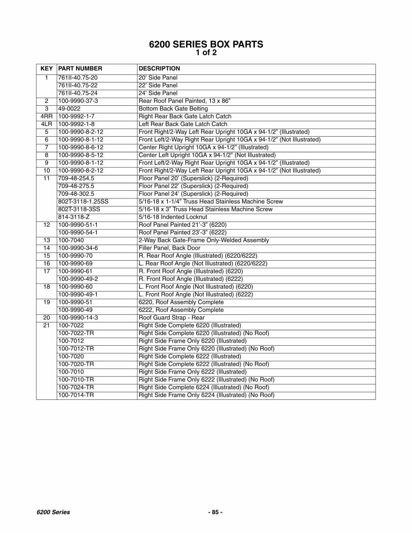
6200 SERIES BOX PARTS1 of 2
KEY PART NUMBER DESCRIPTION
1 761II-40.75-20 20’ Side Panel761II-40.75-22 22’ Side Panel761II-40.75-24 24’ Side Panel
2 100-9990-37-3 Rear Roof Panel Painted, 13 x 86”3 49-0022 Bottom Back Gate Belting
4RR 100-9992-1-7 Right Rear Back Gate Latch Catch4LR 100-9992-1-8 Left Rear Back Gate Latch Catch
5 100-9990-8-2-12 Front Right/2-Way Left Rear Upright 10GA x 94-1/2” (Illustrated)6 100-9990-8-1-12 Front Left/2-Way Right Rear Upright 10GA x 94-1/2” (Not Illustrated)7 100-9990-8-6-12 Center Right Upright 10GA x 94-1/2” (Illustrated)8 100-9990-8-5-12 Center Left Upright 10GA x 94-1/2" (Not Illustrated)9 100-9990-8-1-12 Front Left/2-Way Right Rear Upright 10GA x 94-1/2” (Illustrated)10 100-9990-8-2-12 Front Right/2-Way Left Rear Upright 10GA x 94-1/2” (Not Illustrated)11 709-48-254.5 Floor Panel 20’ (Superslick) (2-Required)
709-48-275.5 Floor Panel 22’ (Superslick) (2-Required)709-48-302.5 Floor Panel 24’ (Superslick) (2-Required)802T-3118-1.25SS 5/16-18 x 1-1/4” Truss Head Stainless Machine Screw802T-3118-3SS 5/16-18 x 3” Truss Head Stainless Machine Screw814-3118-Z 5/16-18 Indented Locknut
12 100-9990-51-1 Roof Panel Painted 21’-3” (6220)100-9990-54-1 Roof Panel Painted 23’-3” (6222)
13 100-7040 2-Way Back Gate-Frame Only-Welded Assembly14 100-9990-34-6 Filler Panel, Back Door15 100-9990-70 R. Rear Roof Angle (Illustrated) (6220/6222)16 100-9990-69 L. Rear Roof Angle (Not Illustrated) (6220/6222)17 100-9990-61 R. Front Roof Angle (Illustrated) (6220)
100-9990-49-2 R. Front Roof Angle (Illustrated) (6222)18 100-9990-60 L. Front Roof Angle (Not Illustrated) (6220)
100-9990-49-1 L. Front Roof Angle (Not Illustrated) (6222)19 100-9990-51 6220, Roof Assembly Complete
100-9990-49 6222, Roof Assembly Complete20 100-9990-14-3 Roof Guard Strap - Rear21 100-7022 Right Side Complete 6220 (Illustrated)
100-7022-TR Right Side Complete 6220 (Illustrated) (No Roof)100-7012 Right Side Frame Only 6220 (Illustrated)100-7012-TR Right Side Frame Only 6220 (Illustrated) (No Roof)100-7020 Right Side Complete 6222 (Illustrated)100-7020-TR Right Side Complete 6222 (Illustrated) (No Roof)100-7010 Right Side Frame Only 6222 (Illustrated)100-7010-TR Right Side Frame Only 6222 (Illustrated) (No Roof)100-7024-TR Right Side Complete 6224 (Illustrated) (No Roof)100-7014-TR Right Side Frame Only 6224 (Illustrated) (No Roof)
6200 Series - 85 -
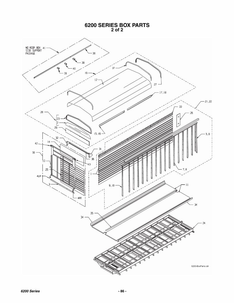
6200 SERIES BOX PARTS2 of 2
6200 Series - 86 -

6200 SERIES BOX PARTS2 of 2
KEY PART NUMBER DESCRIPTION
22 100-7023 Left Side Complete 6220 (Not Illustrated)100-7023-TR Left Side Complete 6220 (Not Illustrated)(No Roof)100-7013 Left Side Frame Only 6220 (Not Illustrated)100-7013-TR Left Side Frame Only 6220 (Not Illustrated)(No Roof)100-7021 Left Side Complete 6222 (Not Illustrated)100-7021-TR Left Side Complete 6222 (Not Illustrated)(No Roof)100-7011 Left Side Frame Only 6222 (Not Illustrated)100-7011-TR Left Side Frame Only 6222 (Not Illustrated)(No Roof)100-7025-TR Left Side Complete 6224 (Not Illustrated)(No Roof)100-7015-TR Left Side Frame Only 6224 (Not Illustrated)(No Roof)
23 100-9990-37-1 Rear Roof Bow & Angle Welded Assy.-Black24 100-7001 Bottom Frame Complete 20’ (10” Stringers)
100-7001-TRUCK Bottom Frame Complete 20’ (6” Stringers)100-7000 Bottom Frame Complete 22’ (10” Stringers)100-7000-TRUCK Bottom Frame Complete 22’ (6” Stringers)100-7002-TRUCK Bottom Frame Complete 24’ (6” Stringers)
25 33-1002 SMV Sign Bracket Only26 100-9990-200-1-1 Auger Bracket Less Tightener27 100-9990-15-1 TSS Roof Bow28 100-9990-37 Rear Roof Bow Assy. Complete29 49-0019 Top Back Gate Belting30 100-7030 6200 Back Gate Assy. Complete W/Latches31 100-9990-115 Right Rear Gate Pivot Support Gusset32 100-9990-116 Left Rear Gate Pivot Support Gusset33 100-9990-8-15 Side Screen 7-1/2 x 82” Painted
100-9990-8-16 Side Screen 7-1/2 x 24” Painted100-9990-8-17 Side Screen 7-1/2 x 80” Painted100-9990-8-18 Side Screen 7-1/2 x 48” Painted
34 25-6005-1 Floor Cap 72”25-8022-1 Floor Cap 96”25-6005-2 Floor Cap 48”25-6006-1 Floor Cap Splice Piece25-8023-1 Floor End Cap
35 100-7000-24 240” Center Superslick Channel-(Common on all lengths)100-7002-2 6224 Center Superslick Channel 55-3/4”100-7000-25 6222 Center Superslick Channel 31-3/4”100-7001-5 6220 Center Superslick Channel 7-3/4”
36 100-9990-87 No Roof Angle37 100-9990-14-4 Front Roof Protector38 100-9990-8-11 16’ & 18’ BOX, SIDE SUPPORT STRAP 171”
100-9990-52-2 20’ & 22’ BOX, SIDE SUPPORT STRAP 219”39 100-9990-52-4 SIDE SUPPORT END TUBE40 100-9990-52-3 SIDE SUPPORT CENTER TUBE41 TSS-SS-16-PKG 16’ & 18’ SIDE SUPPORT PACKAGE
TSS-SS-20-PKG 20’ & 22’ SIDE SUPPORT PACKAGE42 100-9990-25-15 RH BACKGATE HINGE BRACKET WELDMENT W/PIVOT SHAFT STOP WASHER
(SHIP LOOSE)43 100-9990-25-16 LH BACKGATE HINGE BRACKET WELDMENT W/PIVOT SHAFT STOP WASHER
(SHIP LOOSE)
6200 Series - 87 -
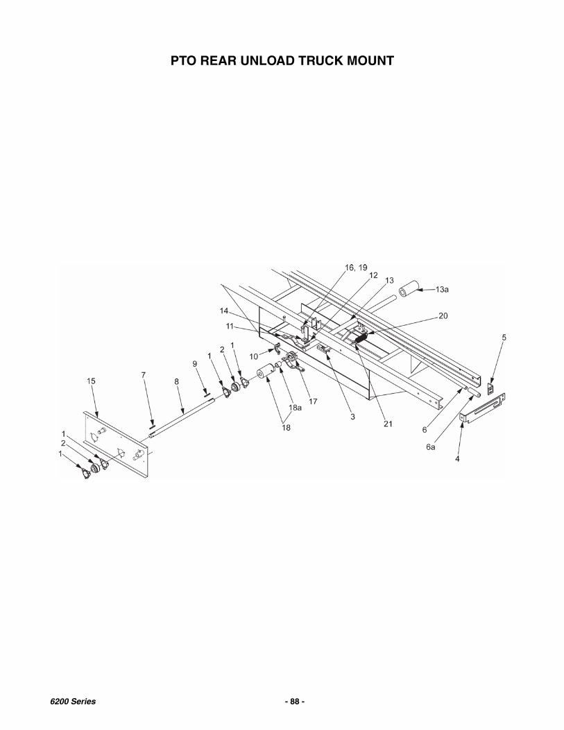
PTO REAR UNLOAD TRUCK MOUNT
6200 Series - 88 -
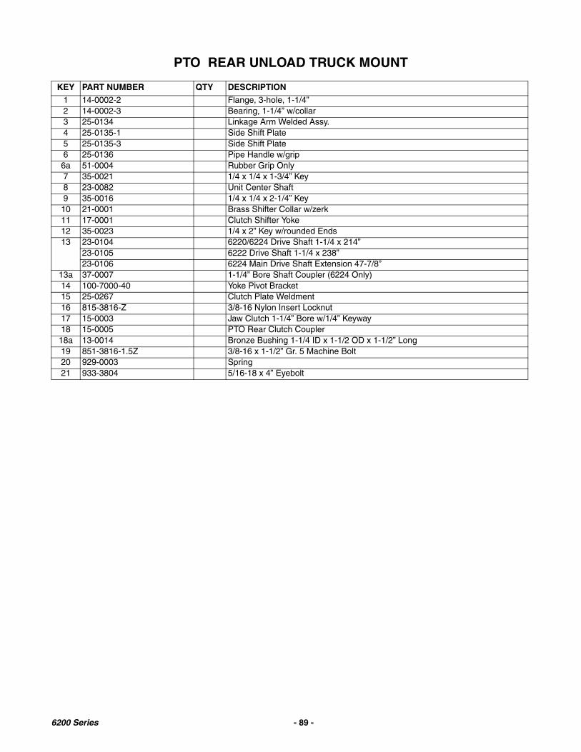
PTO REAR UNLOAD TRUCK MOUNT
KEY PART NUMBER QTY DESCRIPTION
1 14-0002-2 Flange, 3-hole, 1-1/4”2 14-0002-3 Bearing, 1-1/4” w/collar3 25-0134 Linkage Arm Welded Assy.4 25-0135-1 Side Shift Plate5 25-0135-3 Side Shift Plate6 25-0136 Pipe Handle w/grip6a 51-0004 Rubber Grip Only7 35-0021 1/4 x 1/4 x 1-3/4” Key8 23-0082 Unit Center Shaft9 35-0016 1/4 x 1/4 x 2-1/4” Key10 21-0001 Brass Shifter Collar w/zerk11 17-0001 Clutch Shifter Yoke12 35-0023 1/4 x 2” Key w/rounded Ends13 23-0104 6220/6224 Drive Shaft 1-1/4 x 214”
23-0105 6222 Drive Shaft 1-1/4 x 238”23-0106 6224 Main Drive Shaft Extension 47-7/8”
13a 37-0007 1-1/4” Bore Shaft Coupler (6224 Only)14 100-7000-40 Yoke Pivot Bracket15 25-0267 Clutch Plate Weldment16 815-3816-Z 3/8-16 Nylon Insert Locknut17 15-0003 Jaw Clutch 1-1/4” Bore w/1/4” Keyway18 15-0005 PTO Rear Clutch Coupler
18a 13-0014 Bronze Bushing 1-1/4 ID x 1-1/2 OD x 1-1/2” Long19 851-3816-1.5Z 3/8-16 x 1-1/2” Gr. 5 Machine Bolt20 929-0003 Spring21 933-3804 5/16-18 x 4” Eyebolt
6200 Series - 89 -

GRAIN KIT ASSEMBLY
Optional Front Gate Assembly
6200 Series - 90 -
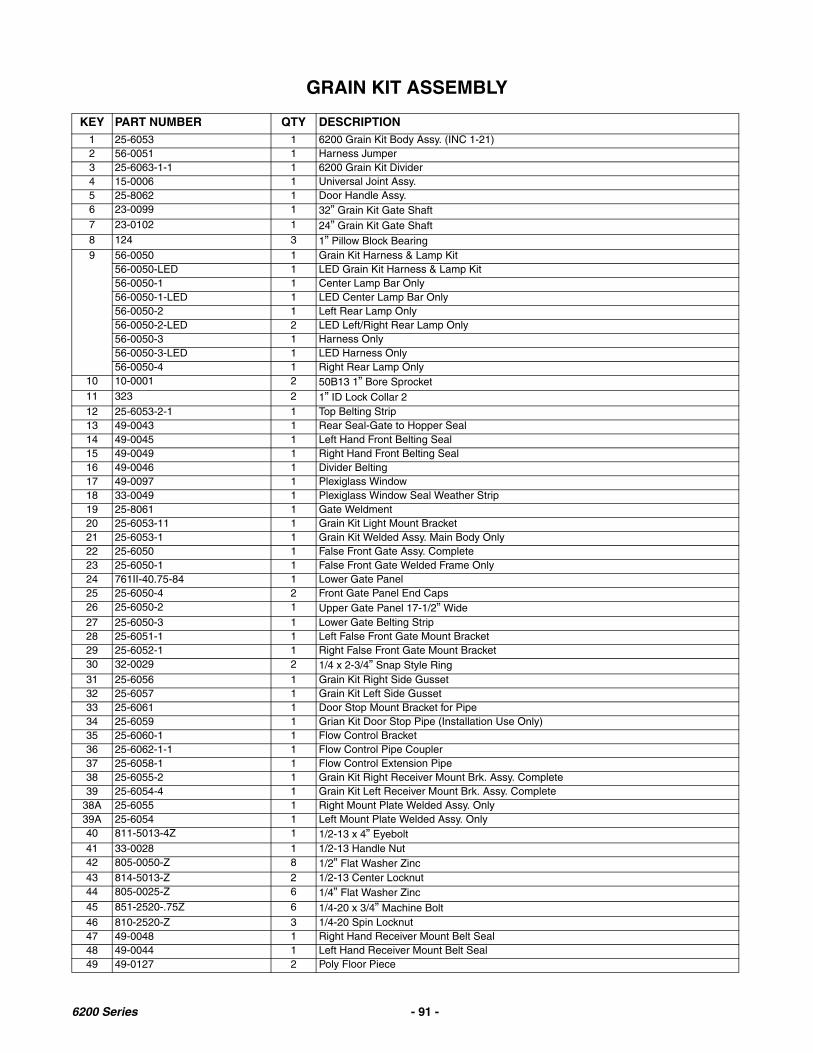
GRAIN KIT ASSEMBLY
KEY PART NUMBER QTY DESCRIPTION1 25-6053 1 6200 Grain Kit Body Assy. (INC 1-21)2 56-0051 1 Harness Jumper3 25-6063-1-1 1 6200 Grain Kit Divider4 15-0006 1 Universal Joint Assy.5 25-8062 1 Door Handle Assy.6 23-0099 1 32” Grain Kit Gate Shaft7 23-0102 1 24” Grain Kit Gate Shaft8 124 3 1” Pillow Block Bearing9 56-0050 1 Grain Kit Harness & Lamp Kit
56-0050-LED 1 LED Grain Kit Harness & Lamp Kit56-0050-1 1 Center Lamp Bar Only56-0050-1-LED 1 LED Center Lamp Bar Only56-0050-2 1 Left Rear Lamp Only56-0050-2-LED 2 LED Left/Right Rear Lamp Only56-0050-3 1 Harness Only56-0050-3-LED 1 LED Harness Only56-0050-4 1 Right Rear Lamp Only
10 10-0001 2 50B13 1” Bore Sprocket11 323 2 1” ID Lock Collar 212 25-6053-2-1 1 Top Belting Strip13 49-0043 1 Rear Seal-Gate to Hopper Seal14 49-0045 1 Left Hand Front Belting Seal15 49-0049 1 Right Hand Front Belting Seal16 49-0046 1 Divider Belting17 49-0097 1 Plexiglass Window18 33-0049 1 Plexiglass Window Seal Weather Strip19 25-8061 1 Gate Weldment20 25-6053-11 1 Grain Kit Light Mount Bracket21 25-6053-1 1 Grain Kit Welded Assy. Main Body Only22 25-6050 1 False Front Gate Assy. Complete23 25-6050-1 1 False Front Gate Welded Frame Only24 761II-40.75-84 1 Lower Gate Panel25 25-6050-4 2 Front Gate Panel End Caps26 25-6050-2 1 Upper Gate Panel 17-1/2” Wide27 25-6050-3 1 Lower Gate Belting Strip28 25-6051-1 1 Left False Front Gate Mount Bracket29 25-6052-1 1 Right False Front Gate Mount Bracket30 32-0029 2 1/4 x 2-3/4” Snap Style Ring31 25-6056 1 Grain Kit Right Side Gusset32 25-6057 1 Grain Kit Left Side Gusset33 25-6061 1 Door Stop Mount Bracket for Pipe34 25-6059 1 Grian Kit Door Stop Pipe (Installation Use Only)35 25-6060-1 1 Flow Control Bracket36 25-6062-1-1 1 Flow Control Pipe Coupler37 25-6058-1 1 Flow Control Extension Pipe38 25-6055-2 1 Grain Kit Right Receiver Mount Brk. Assy. Complete39 25-6054-4 1 Grain Kit Left Receiver Mount Brk. Assy. Complete
38A 25-6055 1 Right Mount Plate Welded Assy. Only39A 25-6054 1 Left Mount Plate Welded Assy. Only40 811-5013-4Z 1 1/2-13 x 4” Eyebolt41 33-0028 1 1/2-13 Handle Nut42 805-0050-Z 8 1/2” Flat Washer Zinc43 814-5013-Z 2 1/2-13 Center Locknut44 805-0025-Z 6 1/4” Flat Washer Zinc45 851-2520-.75Z 6 1/4-20 x 3/4” Machine Bolt46 810-2520-Z 3 1/4-20 Spin Locknut47 49-0048 1 Right Hand Receiver Mount Belt Seal48 49-0044 1 Left Hand Receiver Mount Belt Seal49 49-0127 2 Poly Floor Piece
6200 Series - 91 -

GATE DELAY6200 Box
Prior to serial # 10T3211
OIL CAPACITYWITH 6” OF RAM ROD SHOWING FILLTANK TO TOP WITH LITE HYDRAULIC OIL.
GATE DELAY INSTRUCTIONS & ADJUSTMENTS
The purpose of the gate delay system is to hold the rear swinging gate in the open position until the apron hascleaned all of the forage out of the box. By adjusting the flow control, the speed in which the gate closes can beregulated. When the flow control is properly adjusted the gate will slowly close as the remainder of the forage isbeing unloaded. Once the box is completely unloaded the gate delay will reach a trip position with the trip armmoving the lower cylinder shaft out of the horizontal slot and allow the gate to trip closed and latch. For properoperation, adjust as follows. When the gate is completely closed (tight to rear upright) the cable and eyeboltassembly should be adjusted so the cable has no slack. Cable should be tight but not over tightened. If cable andeyebolt is over tightened, the lower cylinder will trip out of the L-shaped slot on the lower bracket prematurely andthe gate will try to close before the cylinder is fully extended. If the cable and eyebolt is too loose, the lowercylinder will not trip out of the L-shaped slot and the cylinder will reach its maximum stroke and the trip arm will stillnot be in the tripped position allowing the gate to close. The gate will be held open by the top cylinder bracket andthe bracket may become damaged over time. The eyebolt and cable will need to be adjusted periodically tomaintain proper operation.
6200 Series - 92 -
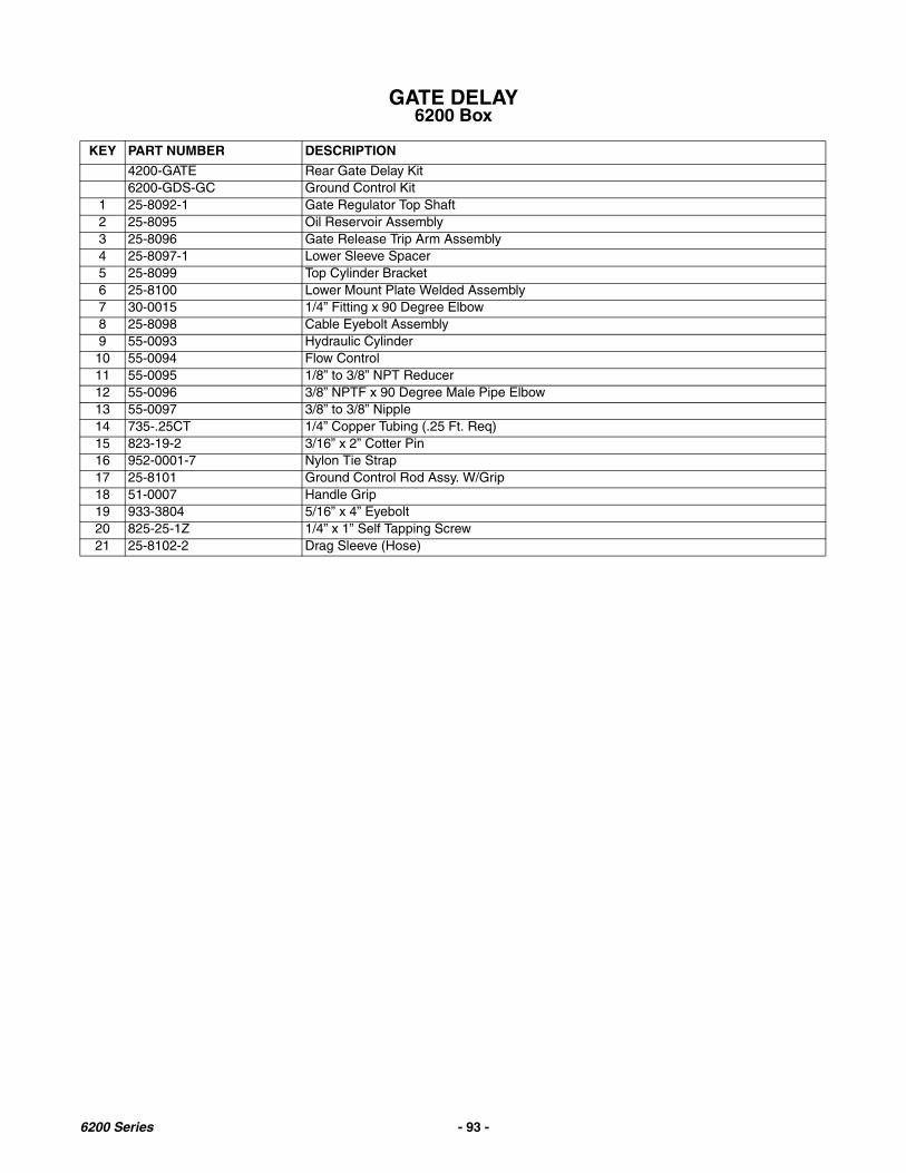
GATE DELAY6200 Box
KEY PART NUMBER DESCRIPTION
4200-GATE Rear Gate Delay Kit6200-GDS-GC Ground Control Kit
1 25-8092-1 Gate Regulator Top Shaft2 25-8095 Oil Reservoir Assembly3 25-8096 Gate Release Trip Arm Assembly4 25-8097-1 Lower Sleeve Spacer5 25-8099 Top Cylinder Bracket6 25-8100 Lower Mount Plate Welded Assembly7 30-0015 1/4” Fitting x 90 Degree Elbow8 25-8098 Cable Eyebolt Assembly9 55-0093 Hydraulic Cylinder10 55-0094 Flow Control11 55-0095 1/8” to 3/8” NPT Reducer12 55-0096 3/8” NPTF x 90 Degree Male Pipe Elbow13 55-0097 3/8” to 3/8” Nipple14 735-.25CT 1/4” Copper Tubing (.25 Ft. Req)15 823-19-2 3/16” x 2” Cotter Pin16 952-0001-7 Nylon Tie Strap17 25-8101 Ground Control Rod Assy. W/Grip18 51-0007 Handle Grip19 933-3804 5/16” x 4” Eyebolt20 825-25-1Z 1/4” x 1” Self Tapping Screw21 25-8102-2 Drag Sleeve (Hose)
6200 Series - 93 -

RETURN LINE GATE DELAY
Serial # 10T3211 & Later
6200 Series - 94 -
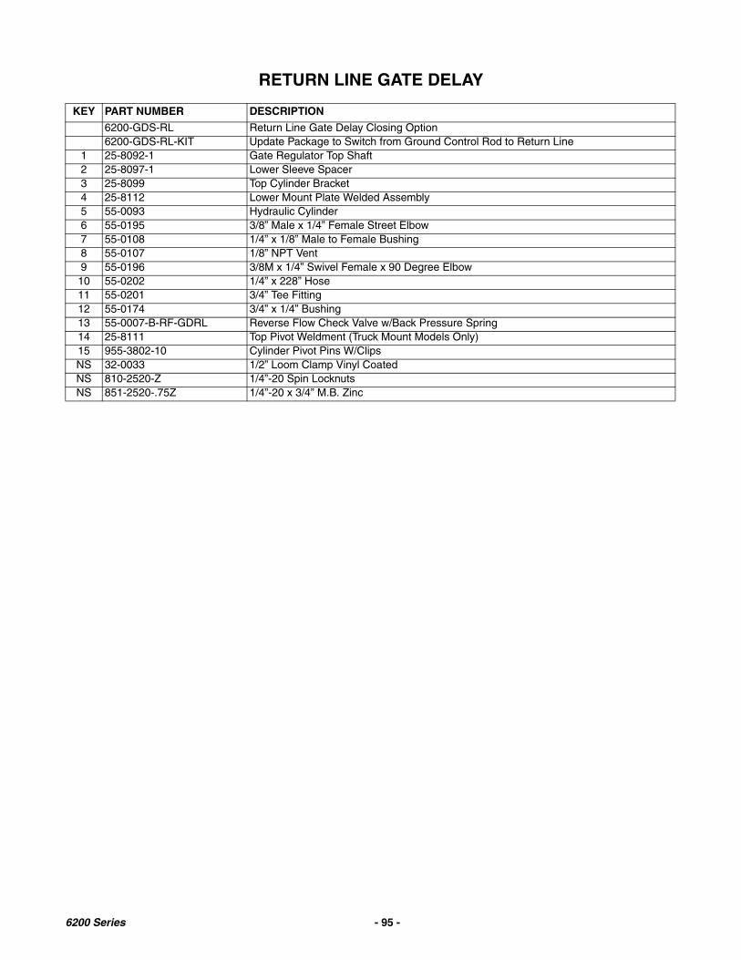
RETURN LINE GATE DELAY
KEY PART NUMBER DESCRIPTION
6200-GDS-RL Return Line Gate Delay Closing Option6200-GDS-RL-KIT Update Package to Switch from Ground Control Rod to Return Line
1 25-8092-1 Gate Regulator Top Shaft2 25-8097-1 Lower Sleeve Spacer3 25-8099 Top Cylinder Bracket4 25-8112 Lower Mount Plate Welded Assembly5 55-0093 Hydraulic Cylinder6 55-0195 3/8” Male x 1/4” Female Street Elbow7 55-0108 1/4” x 1/8” Male to Female Bushing8 55-0107 1/8” NPT Vent9 55-0196 3/8M x 1/4” Swivel Female x 90 Degree Elbow10 55-0202 1/4” x 228” Hose11 55-0201 3/4” Tee Fitting12 55-0174 3/4” x 1/4” Bushing13 55-0007-B-RF-GDRL Reverse Flow Check Valve w/Back Pressure Spring14 25-8111 Top Pivot Weldment (Truck Mount Models Only)15 955-3802-10 Cylinder Pivot Pins W/ClipsNS 32-0033 1/2” Loom Clamp Vinyl CoatedNS 810-2520-Z 1/4”-20 Spin LocknutsNS 851-2520-.75Z 1/4”-20 x 3/4” M.B. Zinc
6200 Series - 95 -
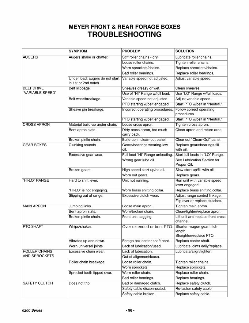
MEYER FRONT & REAR FORAGE BOXESTROUBLESHOOTING
SYMPTOM PROBLEM SOLUTION
AUGERS Augers shake or chatter. Stiff roller chains - dry. Lubricate roller chains.
Loose roller chains. Tighten roller chains.
Worn sprockets/chains. Replace sprockets/chains.
Bad roller bearings. Replace roller bearings.Under load, augers do not start in 1st or 2nd notch.
Variable speed not adjusted. Adjust variable speed.
BELT DRIVE“VARIABLE SPEED”
Belt slippage. Sheaves greasy or wet. Clean sheaves.
Use of “HI” Range w/full load. Use “LO” Range w/full loads.
Belt wear/breakage. Variable speed not adjusted. Adjust variable speed.PTO starting w/belt engaged. Start PTO w/belt in “Neutral.”
Sheave pin breakage. Incorrect operating procedures. Follow correct operating procedures.
PTO starting w/belt engaged. Start PTO w/belt in “Neutral.”
CROSS APRON Material build-up under chain. Loose cross apron. Tighten cross apron.Bent apron slats. Dirty cross apron, too much
carry back.Clean apron and return area.
Broken pintle chain. Build-up in clean-out panel. Clear out “Clean-Out” panel.
GEAR BOXES Clunking sounds. Gears/bearings wearing-lowoil.
Replace gears/bearings-fillwith oil.
Excessive gear wear. Full load “HI” Range unloading. Start full loads in “LO” Range.
Wrong gear lube oil. See Lubrication Section forProper Oil.
Broken gears. High speed start-up/no oil. Slow start-up/fill with oil.Worn out gears. Replace gears.
“HI-LO” RANGE Hard to shift lever. Unit not running. Run unit with variable speedlever engaged.
“HI-LO” is not engaging. Worn brass shifting collar. Replace brass shifting collar.
Slipping out of range. Excessive clutch wear. Adjust range control linkage.Flip over or replace clutches.
MAIN APRON Jumping links. Loose main apron. Tighten main apron.
Bent apron slats. Worn/broken chain. Clean/tighten/replace apron.Broken pintle chain. Front unit sagging. Lift unit and replace front cross
channel.PTO SHAFT Whips/shakes. Over extended or bent PTO. Shorten wagon gear hitch
length.Straighten/replace PTO.
Vibrates up and down. Forage box center shaft bent. Replace center shaft.Worn universal joints. Lack of lubrication/used. Lubricate joints daily/replace.
ROLLER CHAINSAND SPROCKETS
Excessive chain wear. Lack of lubrication. Lubricate/align/tighten.
Out of alignment/loose.
Roller chain breakage. Loose roller chain. Tighten roller chains.Worn sprockets. Replace sprockets.
Sprocket teeth tipped over. Worn roller chain. Replace roller chain.
Bad roller bearings. Replace bearings.SAFETY CLUTCH Does not trip. Bad or damaged clutch. Replace safety clutch.
Safety cable disconnected. Re-fasten safety cable.
Safety cable broken. Replace safety cable.
6200 Series - 96 -

MEYER FRONT & REAR FORAGE BOXESSPECIFICATIONS
See the "Forage Truck Mount Specifications and Mounting Instructions" for additional information. Theseinstructions may also be found at www.meyermfg.com/specifications.php.
MODEL 6220 6222 6224
Floor Length 20’-6" 22’-6" 24’-6”
Overall Length 24’-2" 26’-2" 28’-2”
Weight
Main Apron 667X StandardOverall Width All Models 107”
Inside Width All Models 87”
Overall Height All Models 126” w/RoofAll Models 105” (+ 12” for gate pivot) w/o Roof
Inside Height All Models 106” w/RoofSpeed SelectionFront Unload
All Models- Low Range: 0 - 9.45’/minute- High Range 0 - 17’/minute
Speed SelectionRear Unload
(PTO Drive) All Models-Approximately 30 Second Unloading Time
Auger Feathering System All Models-Standard Equipment
Power Source 540 PTO and Hydraulic
Cross Feed Delivery Either Left or Right Hand DischargeUnloading Auger 3 Large 18" Diameter Augers and 1 - 11 1/2” Diameter Auger
Cross Conveyor Chain D662 Pintle Chain
Cross Conveyor Width All Models-21”Box Tie Down Kit All Models-Standard Equipment
Cross Conveyor Outfeed 24" Fold-up Standard
Safety Clutch All Models Standard Equipment
SPECIFICATIONS SUBJECT TO CHANGE WITHOUT NOTICE.
6200 Series - 97 -

Meyer Manufacturing Corporation574 West Center Avenue
Dorchester, WI 54425Phone: 1-800-325-9103
Fax: 715-654-5513Email: [email protected]: www.meyermfg.com
6200 Series - 98 -
MAINTENANCE RECORD
MODEL NO. ________________________________ SERIAL NO. _______________________________
DATE SERVICE PERFORMED DATE SERVICE PERFORMED
Manufactured by:
Meyer Mfg. Corp.574 West Center Avenue
Dorchester, WI 54425Phone: 1-800-325-9103
Fax: 715-654-5513Email: [email protected]: www.meyermfg.com
Farm Equipment Buyers Trust the Name Meyer!

Meyer Manufacturing Corporation574 West Center Avenue
Dorchester, WI 54425Phone: 1-800-325-9103
Fax: 715-654-5513Email: [email protected]: www.meyermfg.com