operator's and service parts manual · representation or warranty concerning its machinery and...
TRANSCRIPT
903032
Form No.
'903467 Replaces
®
OPERATOR'S AND SERVICE PARTS MANUAL

GEHL®COMPANY
New Agricultural Equipment
Gehl Company (Incorporated), hereinafter referred to as GEHL, as manufacturer of quality machinery since 1859, warrants new G EH L machinery and / or attachments at the time of delivery to the original purchaser to be free from defects in material and workmanship if properly set up and operated in accordance with the recommendations set forth in G EH L's Operator Manual.
GEHL's liability for any defect with respect to accepted goods shall be limited to repairing the goods at an authorized GEHL dealer or other GEHL designated location, or replacing them, as GEHL shall elect. The above shall be in accordance with GEHL warranty adjustment policies. GEHL's obligation shall terminate twelve (12) months after the delivery of the goods to the original purchaser.
This warranty shall not apply to any machine or attachment which shall have been repaired or altered outside the G E H L factory or authorized G EH L dealership or in any way so as in G EH L's judgment, to affect its stability or reliability, nor which has been subject to misuse, negligence or accident, nor to any machine or attachment which shall not have been operated in accordance with GEHL's printed instructions or beyond the company recommended machine rated capacity.
This warranty shall not be applicable to items which are subject to the warranties of their respective manufacturers. Such items would include but would not be limited to engines, clutches, universaljoints, knives, hydraulic components, bearings, tires, belts and other trade accessories.
EXCLUSION OF WARRANTIES
Except as otherwise expressly stated herein, GEH L makes no representation or warranty of any kind, express or implied, AND MAKES NO WARRANTY OF MERCHANTABILITY IN RESPECT TO ITS MACHINERY AND/OR ATTACHMENTS AND MAKES NO WARRANTY THAT ITS MACHINERY AND / OR ATTACHMENTS ARE FIT FOR ANY PARTICULAR PURPOSE. GEHLshall not be liable for incidental or consequential damages for any breach of warranty, including but not limited to inconvenience, rental or replacement equipment, loss of profits or other commercial loss. GEH L shall not be liable for, and the buyer assumes all liability for, all personal injury and property damage resulting from the handling, possession or use of the goods by the buyer.
No agent, employee or representative of GEHL has any authority to bind GEHL to any affirmation, representation or warranty concerning its machinery and / or attachments except as specifically set forth herein.
2

CHAPTER 1 INTRODU CTION
Mr. Operator:
Your decision to purchase this piece of G E H L eq ui pment was a good one. We are sure that your decision was strongly considered and that you are looking forward to many seasons of work from this machine.
We, as a Company, have invested a great deal of time and effort in developing our lines o f agricultural and industrial equipment. The equipment you have purchased is built with a great deal of pride and designed to give you long life, efficient operation, durability and dependability.
This manual was developed specifically for the machine you have purchased. The information, contained within, was prepared for your assistance in preparing, adjusting, maintaining and servicing your machine . More importantly, this manual provides an operating plan for safe and proper use of your machine . Major points of safe operation are detailed in the SAFETY chapter of this manual. Refer to the Table of Contents for an outline (by chapters) of this manual. Use the Index, in the back of the manual, for specific chapter and topic / page number references.
Modern machinery has become more sophisticated and, with that in mind, GEHL Company asks that you read and understand the contents of this man ual COMPLETELY and become familiar with your new machine, BEFORE attempting to operate it.
Our wide Dealership network stands by to provide you with any assistance you may require, including genuine GEHL service parts. All parts should be obtained from or ordered through your G E H L Dealer. Give complete information about the part as well as the model number and the serial number of your machine. Record numbers, in space provided, as a handy record for quick reference.
Typical Model & S~rial No. Plate
MODEL NO. .~
WR2~
SERIAL NO. .~
(Filll.~ GEHL COMPANY
WEST BEND, WIS. 53095 U.S.A.
"Right" and "Left" are determined from a posItIOn standing behind the Rake and facing the direction of tra vel. From this position, the Ora wbar Adj ustment is on the "Left" Side.
Numbers for this unit are stamped on a plate located on the Main Frame.
G E H L Company reserves the right to make changes or improvements in the design or construction of any part without incurring the obligation to install such changes on any unit previously delivered .
Standard hardware torques appear in a chart at the end of the manual.
Throughout this manual, information is provided which is set in bold type and introduced by the word NOTE. BE SURE to read carefully and comply with the message or directive given . Following this information will improve your operating or maintenance efficiency, help you to avoid costly breakdown or unnecessary damage and, extend your machine's life.
The GEHL Company and the American Society of Agricultural Engineers have adopted this SAFETY ALERT SYMBOL
to pinpoint characteristics which, if not properly followed, can create a safety hazard. When you see this symbol in this manual or on the unit itself, you are reminded to BE ALERT! Your Safety is involved.
TABLE OF CONTENTS Page
Warranty ...................................... 2 Introd uction ................................... 3 Specifications .................................. 4 Check Lists .................................. 5-7 Safety ......................................... 8 General Information ......................... 9-18 Service Parts ............................... 20-23 Decal Locations ............................... 24 Numerical Index ............................... 25 Index ........................................ 27
3

SPECIFICATIONS
Dimensions are in Inches (Millimeters) Unless Otherwise Noted
Model & Description ..... WR206 Finger Wheel Rake Operating Width (Adjustable) ....... 6-1/2 to 9-3/4 ft
(2 to 3) Transport Width ....................... 9 ft (2-3/4) Height in Transport ................. . 55-1/8 (1400) Finger Wheel Diameter ............... 55-1/8 (1400) Number of Finger Wheels ........................ 6 Number of Tines on Each Wheel ................ .40 Unit Weight (Approximate) .......... 840 lb (385 kg) Wheel Size ..... 4.5 x 15 Rims (Purchase Tires locally)
4

__
CHECKLISTS
PRE-DELIVERY-c o After the Wheel Rake has been completely set-up, the ::: ...m following inspections should be made before delivering it
-o to the Customer. Check off each item after prescribed... Q) action is taken.
Q.
< Check that:
Dealer's Name
By ____~=-~~~--~~~_=~-----------Dealer's Set-up Man's Signature
Date Set-up _________________
Serial Number________________
DELIVERY
The following Check List is an important reminder of valuable information that MUST be passed on to the Customer at the time the unit is delivered. Check off each item as you explain it to the Customer.
__ Give the Customer his Operator's Manual. Instruct him to be sure to read and completely understand its contents BEFORE attempting to operate his unit.
__ Explain and review with him the SAFETY information.
__ Explain to him that regular lubrication is required for continued proper operation and long life. Review with him the Lubrication information in this manual.
Completely fillout Owner's Registration, including Customer's signature, and return it" to the GEHL Company.
I acknowledge that above points were reviewed with me at the time of delivery.
Customer's Signature
Date Delivered ________________
(Dealer's File Copy)
~ c. o o ~ iL __ U) ~... Q)
'ii Q) __ c Q) __>o E Q)
a:-
Wheel Rake has been completely and properly setup according to the details in this manual.
All Grease Fittings have been properly lubricated~ see Lubrication information.
All fasteners are properly secured.
Record the Serial N umber of this unit on this page and page 3.
5

INTENTIONALLY BLANK (To be removed as Dealer's File Copy)
6
CHECK LISTS
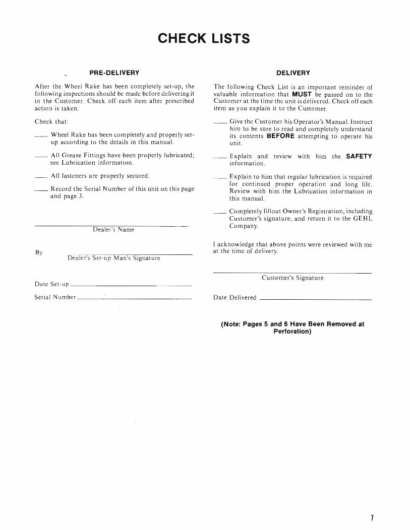
PRE-DELIVERY
After the Wheel Rake has been completely set-up, the following inspections should be made before delivering it to the Customer. Check off each item after prescribed action is taken.
Check that:
__ Wheel Rake has been completely and properly setup according to the details in this manual.
__ All Grease Fittings have been properly lubricated; see Lubrication information.
__ All fasteners are properly secured.
__ Record the Serial Number of this unit on this page and page 3.
Dealer's Name
By ______~--~~--------~~---------------Dealer's Set-up Man's Signature
Da te Set -up _________________________________
Seria I Number _______________________________
DELIVERY
The following Check List is an important reminder of valuable information that MUST be passed on to the Customer at the time the unit is delivered. Check off each item as you explain it to the Customer.
__ Give the Customer his Operator's Manual. Instruct him to be sure to read and completely understand its contents BEFORE attempting to operate his unit.
__ Explain and review with him the SAFETY information.
__ Explain to him that regular lubrication is required for continued proper operation and long life. Review with him the Lubrication information in this manual.
__ Completely fillout Owner's Registration, including Customer's signature, and return it to the G EHL Company.
I acknowledge that above points were reviewed with me at the time of delivery.
Customer's Signature
Date Delivered ___________________________
(Note: Pages 5 and 6 Have Been Removed at Perforation)
7
SAF
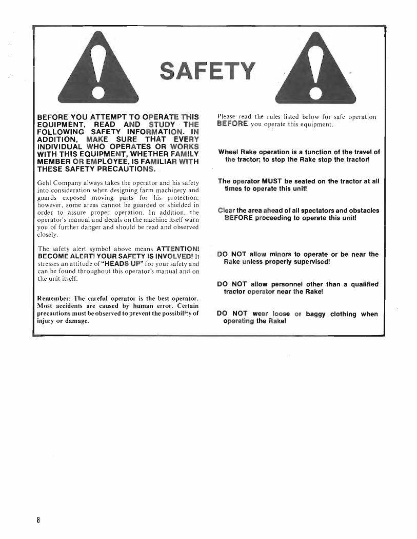
BEFORE YOU ATTEMPT TO OPERATE -THIS EQUIPMENT, READ AND STUDY THE FOLLOWING SAFETY INFORMATION. IN ADDITION, MAKE SURE THAT EVERY INDIVIDUAL WHO OPERATES OR WORKS WITH THIS EQUIPMENT, WHETHER FAMILY MEMBER OR EMPLOYEE, IS FAMILIAR WITH THESE SAFETY PRECAUTIONS.
Gehl Company always takes the operator and his safety into consideration when designing farm machinery and guards exposed moving parts for his protection; however, some areas cannot be guarded or shielded in order to a ssure proper operation. I n addition, the operator's manual and decals on the machine itself warn you of further danger and should be read and observed closely.
The safety alert symbol above means ATTENTION! BECOME ALERT! YOUR SAFETY IS INVOLVED! It stresses an attitude of "HEADS UP" for your safety and can be found throughout this operator's manual and on the unit itself.
Remember: The careful operator is the best o perator. Most accidents are caused by human error. Certain precautions must be observed to prevent the possibility of injury or damage.
TV
Please read the rules listed below for safe operation BEFORE you operate this equipment.
Wheel Rake operation is a function of the travel of the tractor; to stop the Rake stop the tractor~
The operator MUST be seated on the tractor at all times to operate this unit!
Clear the area ahead of all spectators and obstacles BEFORE proceeding to operate this unit!
DO NOT allow minors to operate or be near the Rake unless properly supervised!
DO NOT allow personnel other than a qualified tractor operator near the Rake!
DO NOT wear loose or baggy clothing when operating the Rake!
8
GENERAL INFORMATION
The following abbreviations are used in this information: (2) Tubes for Finger Wheel Support
HFLS - Hexagon Flanged Lock Screw HHCS - Hexagon Head Cap Screw HLN - Hexagon Lock Nut HN - Hexagon Nut SW - Star Washer NlLN - Nylon Insert Lock Nut
General Bolt Torque Data in Ft-Lb*
BOLT GRADE SIZE 8.8 10.9 12.9
Metric DRY LUB. DRY LUB. DRY LUB.
M6 8 6 II 8 13.5 10 M8 19 14 27 20 32.5 24 MIO 37.5 28 53 39 64 47 MI2 65 48 91.5 67.5 111.3 82 MI4 103.5 76.5 145.5 108 176.5 131 MI6 158.5 117.5 223.5 165.5 271 200.5
*Multiply by (1.383) for metric N-m
The GEHL WR206 Wheel Rake is a trail-behind grounddriven Finger Wheel Rake suitable for windrowing hay, stra w, grass, etc. The W R206 has inflated rubber Tires mounted in the middle of the Main Frame. Three Finger Wheel assemblies are provided ahead of and behind the Tires to maintain proper balance. The Finger Wheels are adjustable to alter the overall operating width from 6-1 2 to 9-3 4 ft (2 to 3 m).
As a trail-behind Rake, the WR206 is ideal for particular field conditions where obstacles, such as trees, may be encountered. The Rake continues to turnout regular windrows, even through the curves and around 0 bstacles. The most satisfactory method is to start in the middle of the field and then move in the counterclockwise direction. The Finger Wheel pressure on the ground is most important to achieving clean raking. If too much pressure is applied against the ground, unnecessary dirt and trash will be brought into the windrow. Although the Finger Wheel Rake has a considerable working width, when working with grass or hay, it is recommended that the windrow is made NO wider than the pickUp capacity of the baler or harvester. In straw or other light crops, the maximum width can be utilized.
PACKING
The GEHL WR206 Finger Wheel rake is packaged partially disassembled for shipment. In general, the following components will have to be assembled to compose an operational unit:
(2) Wheel Axles
(2) 4.5 x 15 Wheel Rims
(I) Front Drawbar and (I) Rear Drawbar
(I) Main Frame
(2) Finger Wheel Supports and (6) Finger Wheels
(I) Adjuster with Spring
(I) Locking Pin with Mounting Straps and (I) Bag of small parts and hardware
NOTE: Tires MUST be purchased locally.
TRACTOR PROVISIONS
The WR206 should be attached to a tractor drawbar which is adjusted to a distance of approximately 14 to 16" (356 to 406 mm). The tractor should also be equipped with an independent hydraulic circuit to operate a (customer provided) hydraulic lift cylinder on the Rake. Quick-disconnect fittings will also have to be customer provided.
RAKE ASSEMBLY
Begin Rake assembly by first removing the components from the shipping crate and lay them out in position for assembly. Before referring to the parts illustrations in the back of this manual and proceeding, BE SURE to remove paint and plastic coating all turning parts and lubricate them lightly to facilitate assembly.
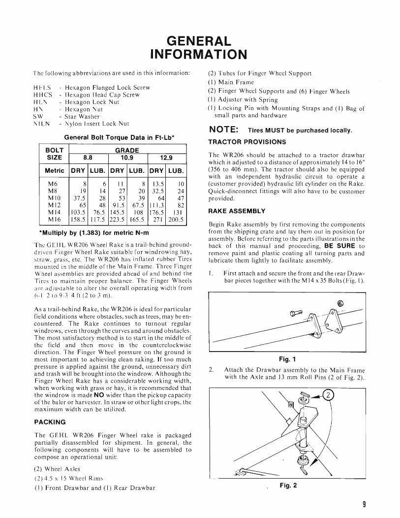
I. First attach and secure the front and the rear Drawbar pieces together with the M 14 x 35 Bolts (Fig. I).
2.
Fig. 1
Attach the Drawbar assembly to the Main Frame with the Axle and 13 mm Roll Pins (2 of Fig. 2).
Fig. 2
9

3. Mount the Wheel Axles to the Main Frame with the 10 mm Roll Pins (Fig. 3).
Fig. 3
4 . After the Tires are mounted on the Rims, attach the Wheels to the Wheel Hubs (Fig. 4).
5. Mount the Finger Wheel Support Tubes (5 of Fig. 5) onto the Main Frame with the Axle (6 of Fig. 5) and 13 x 90 Roll Pins. The Tubes can be attached either way on the Axle, front or back. However the Welded Straps on the Tubes MUST be oriented so they face up on both Tubes (7 of Fig. 5).
6. Fasten the Triangle Plate (8 of Fig. 6) with its Welded Pins onto the Main Frame.
Fig. 5 NOTE: Refer to Fig. 7 for assembled view.
Fig. 4
Front~
Fig. 6
10
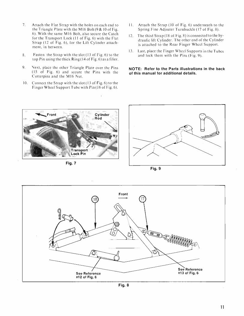
Fig. 7
Front
7. Attach the Flat Strap with the holes on each end to the Triangle Plate with the M 16 Bolt (9 & 10 of Fig. 6). With the same M 16 Bolt, also secure the Catch for the Transport Lock (II of Fig. 6) with the Flat Strap (12 of Fig. 6), for the Lift Cylinder attachment, in between.
8. Fasten the Strap with the slot (13 of Fig. 6) to the top Pin using the thick Ring( 14 of Fig. 6) as a filler.
9. Next, place the other Triangle Plate over the Pins (15 of Fig. 6) and secure the Pins with the C otterpins and the M 16 Nut.
10. Connect the Strap with the slot (13 of Fig. 6) to the Finger Wheel Support Tube with Pin (16 of Fig. 6).
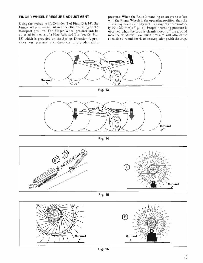
II. Attach the Strap (10 of Fig. 6) underneath to the Spring Fine Adjuster Turnbuckle (17 of Fig. 8).
12. The third Strap (18 of Fig. 8) is connected to the hydraulic lift Cylinder. The other end of the Cylinder is attached to the Rear Finger Wheel Support.
13. Last, place the Finger Wheel Supports in the Tubes and lock them with the Pins (Fig. 9).
NOTE: Refer to the Parts illustrations in the back of this manual for additional details.
Fig. 9
See Reference #12 of Fig. 6
Fig. 8
11

FINGER WHEEL HUBS
Disassemble the Finger Wheel Hubs (Fig. 10 or 11) from the Carriers and mount them to the Finger Wheels with the (6) Bolts provided.
NOTE: The Reinforcing Flanges of the Finger Wheel Hubs MUST be properly oriented to be on the side opposite the force of the crop as shown in either Fig. 10 or 11. This is necessary to insure proper support and to help prevent the Bolt Heads from fatiguing the Wheel Reinforcing Flanges. With the Wheel correctly oriented, push the Finger Wheel and Bearing onto the Finger Wheel Support.
Fig. 10: Finger Wheel Before Serial #2568
For a WR206 Rake before Serial #2568, BE SURE to install a Filling Ring on each side of the assembly as shown in Fig. 10. The Closing Ring MUST also be correctly positioned and assembled so that the small alignment dimple fits into a mating recess on the Axle Shaft to prevent the Closing Ring from turning. Attach and secure the Ring with the 10 mm Bolt provided.
Fig. 11: Finger Wheel After Serial #2567.
For a WR206 Rake after Serial #2567, the Closing Ring MUST be correctly positioned and assembled so that the small hole for the Roll Pin is lined-up with the mating hole in the Axle Shaft as shown in Fig. 11. The Roll Pin MUST then be installed to prevent the Ring from turning. Attach and secure the Ring with the 10 mm Bolt provided.
NOTE: After the Finger Wheels are properly assembled, the Front Three Finger Wheels will display a larger gap between the Anti-wrapping Shield on the Support Arm and the Reinforcing Flange on the Finger Wheel 'than 'the gap displayed on the back three Finger Wheels because of the proper but different orientation of the Finger Wheel Hubs (Fig. 12).
Fig. 12
12
FINGER WHEEL PRESSURE ADJUSTMENT
Using the hydraulic lift Cylinder (l of Figs. 13 & 14), the Finger Wheels can be put in either the operating or the transport position. The Finger Wheel pressure can be adjusted by means of a Fine Adjusted Turnbuckle (Fig. IS) which is provided on the Spring. Direction A provides less pressure and direction B provides more
pressure. When the Rake is standing on an even surface with the Finger Wheels in the operating position, then the Tines may have flexibility within a range of approximately 10" (250 mm) (Fig. 16). Proper operating pressure is obtained when the crop is cleanly swept off the ground into the windrow. Too much pressure will also cause excessive dirt and debris to be swept along with the crop.
Ground
Fig. 13
Fig. 14
Fig. 15
®
Fig. 16
13
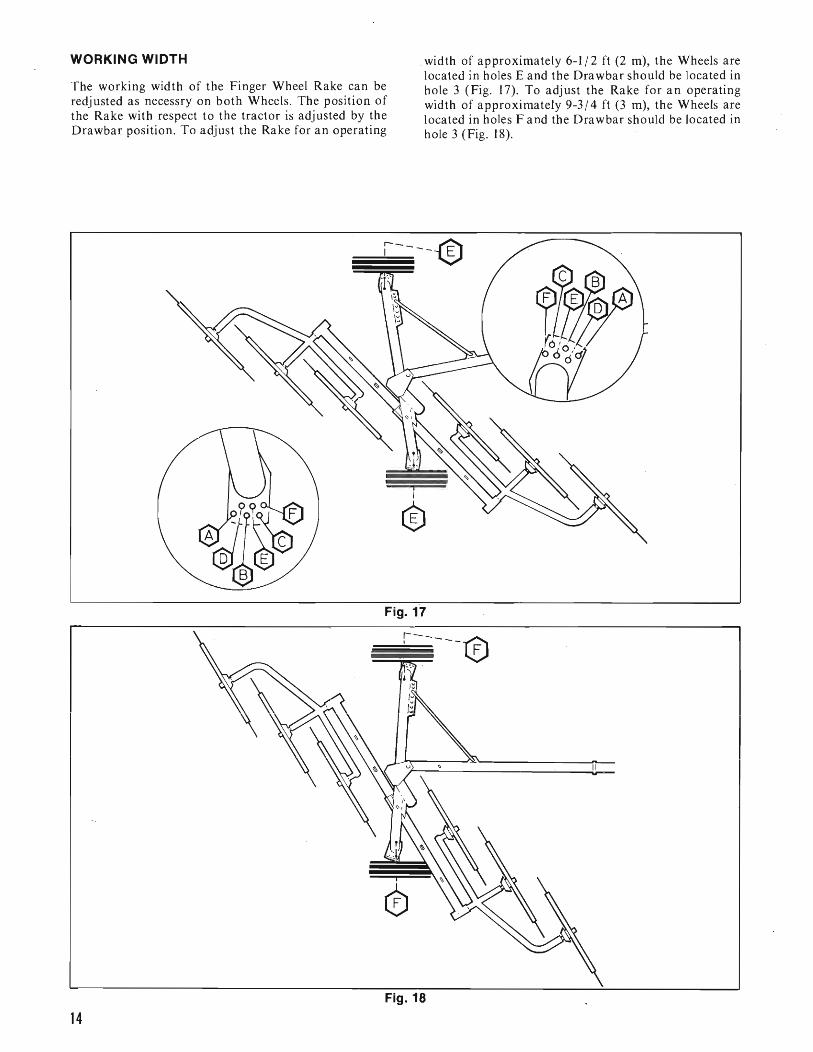
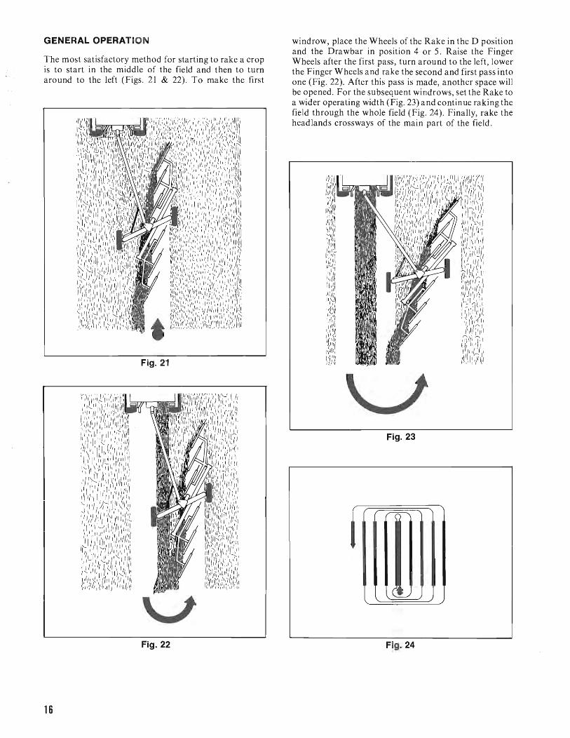
WORKING WIDTH width of approximately 6-1/2 ft (2 m), the Wheels are located in holes E and the Orawbar should be located in
The working width of the Finger Wheel Rake can be hole 3 (Fig. 17). To adjust the Rake for an operating redjusted as necessry on both Wheels. The position of width of approximately 9-3/4 ft (3 m), the Wheels are the Rake with respect to the tractor is adjusted by the located in holes F and the Orawbar should be located in Orawbar position. To adjust the Rake for an operating hole 3 (Fig. 18).
~r;;;-----®
i I
®
Fig. 17
=r=-----e ':.-:,,,
I
cD
Fig. 18
14

For raking along ditches and trenches or other partitions, into holes A and the Drawbar into holes 6 or 7 (.Fig. 20). place the Wheels into holes E and the Drawbar into hole I Additional holes provide other selectable intermediate (Fig. 19). For transporting the Rake, place the Wheels positions.
r-- __-@
Fig. 19
o !.
Fig. 20
15
GENERAL OPERATION
The most satisfactory method for starting to rake a crop is to start in the middle of the field and then to turn around to the left (Figs. 21 & 22). To make the first
Fig. 21
v Fig. 22
windrow, place the Wheels of the Rake in the D position and the Drawbar in position 4 or 5. Raise the Finger Wheels after the first pass, turn around to the left, lower the Finger Wheels and rake the second and first pass into one (Fig. 22). After this pass is made, another space will be opened. For the subsequent windrows, set the Rake to a wider operating width (Fig. 23) and continue raking the field through the whole field (Fig. 24). Finally, rake the headlands crossways of the main part of the field.
Fig. 23
i
Fig. 24
16

NOTE: For raking windrows made with a Disc Conditioner or Mower Conditioner, the Rake right away should be set to the maximum operating width of 9-3/4 ft (3 m) (Figs. 25 & 26).
TRANSPORTING
For transporting the Rake, the Finger Wheels should be raised to their highest positions with the hydraulic cylinder (Fig. 27) and the Lock Pin should be installed (Fig. 28). Place the Wheels in position A and the Drawbar into hole 6 or 7 (Fig. 29).
r--
, "
'--.: L
Fig. 25
Fig. 26
Fig. 27
17
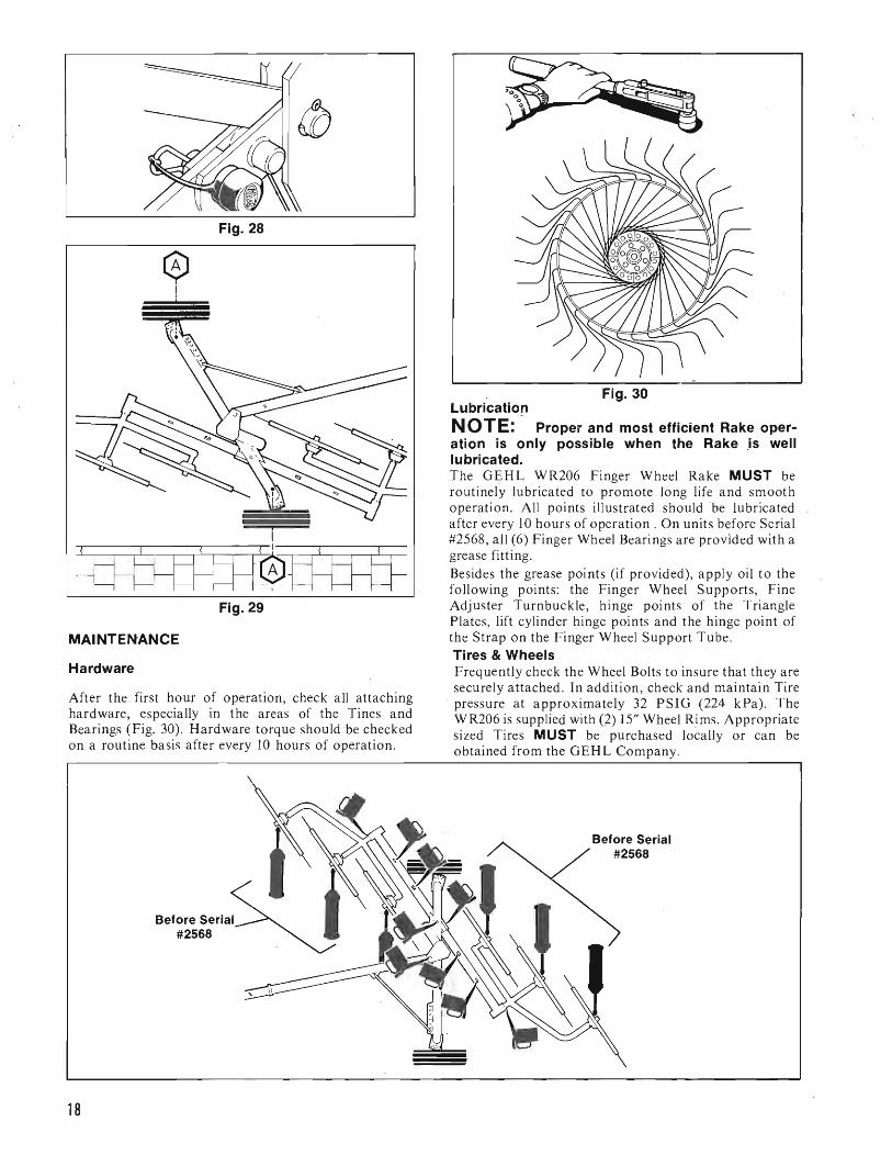
Fig. 28
o !,
Fig. 29
MAINTENANCE
Hardware
After the first hour of operation, check all attaching hardware, especially in the areas of the Tines and Bearings (Fig. 30). Hardware torque should be checked on a routine basis after every 10 hours of operation.
Fig. 30 Lubrication NOTE: Proper and most efficient Rake operation is only possible when the Rake .is well lubricated. The GEHL WR206 Finger Wheel Rake MUST be routinely lubricated to promote long life and smooth operation. All points illustrated should be lubricated after every 10 hours of operation. On units before Serial #2568, all (6) Finger Wheel Bearings are provided with a grease fitting. Besides the grease points (if provided), apply oil to the following points: the Finger Wheel Supports, Fine Adjuster Turnbuckle, hinge points of the Triangle Plates, lift cylinder hinge points and the hinge point of the Strap on the Finger Wheel Support Tube. Tires & Wheels Frequently check the Wheel Bolts to insure that they are securely attached . In addition, check and maintain Tire pressure at approximately 32 PSIG (224 kPa). The WR206 is supplied with (2) IS" Wheel Rims. Appropriate sized Tires MUST be purchased locally or can be obtained from the GEHL Company.
\
Before Serial #2568
18

INTENTIONALLY BLANK
19
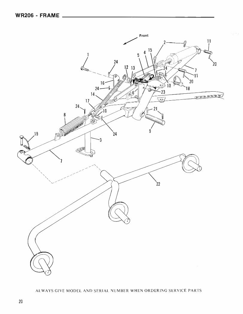
WR206 - FRAME ____________________
Front
/
ALWAYS GIVE MODEL AND SERIAL NUMBER WHEN ORDERING SERVICE PARTS
20
________________________________________WR206-FRAME
REF. PART NO. REF. PART NO. NO. NO. PART NAME REQ. NO. NO. PART NAME REQ.
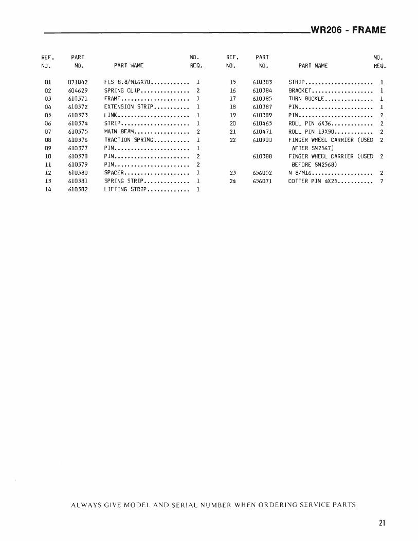
01 071042 FLS 8. 8/MI6X70 •••••••••••• 1 15 610383 STRIP •••••••••.••.••.••••• 1 02 604629 SPRING CLIP •.•••••••••••.• 2 16 610384 BRACKET ••••••...•••••.••.• 1 03 610371 FRAME •••••.•••••••••••.••• 1 17 610385 TURN BUCKLE •.••••••••••••• 1 04 610372 EXTENSION STRIP ••••••••••• 1 18 610387 PIN ••••••••••••• ' .' .••••••• 1 05 610373 LINK •••••••••••••••••••••• 1 19 610389 PIN ••••••.•••••••••.•••••• 2 06 610374 STRIP ••••••••••••••••••••• 1 20 610465 ROLL PIN 6X36 ••••••••••••• 2 07 610375 MAIN BEAM ••••••••••••••••• 2 21 610471 ROLL PIN 13X90 ••••••••.••• 2 08 610376 TRACTION SPRING ••••••••••• 1 22 610900 FINGER WHEEL CARRIER (USED 2 09 610377 PIN •••.••••••••••••••••••• 1 AFTER SN2567) 10 610378 PIN ••••••••••••.•••••••••• 2 610388 FINGER WHEEL CARRIER (USED 2 11 610379 PIN ••••••••••••••••••••••• 2 BEFORE SN2568) 12 610380 SPACER •••••••••••••••••••• 1 23 656052 N 8/MI6 ••••••••••••••••••• 2 13 610381 SPRING STRIP ••••••••••.•.• 1 24 656071 COTTER PIN 4X25 .•••..••••• 7 14 610382 LIFTING STRIP •••••••••.••• 1
ALWAYS GIVE MODEL AND SERIAL NUMBER WHEN ORDERING SERVICE PARTS
21
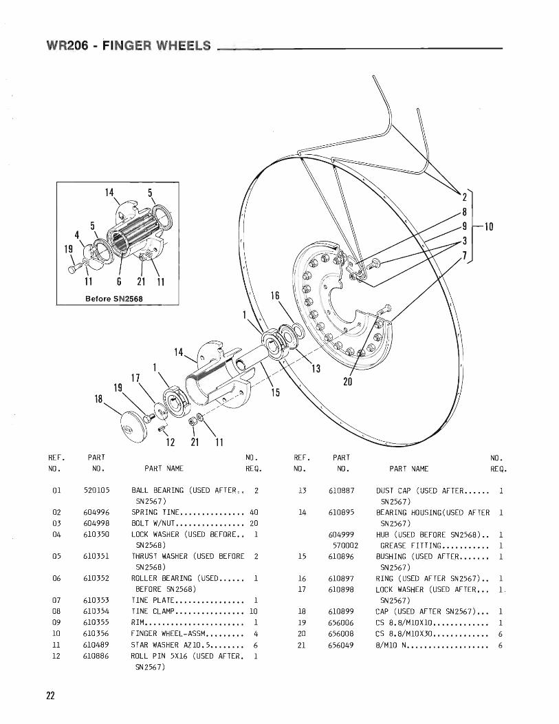
WR206 - FINGER WHEELS
10
11 6 21 11 Before SN2568
14
REF. PART NO. REF. PART NO. NO. NO. PART NAME REQ. NO. NO. PART NAME REQ.
01 520105 BALL BEARING (USED AFTER.; 2 13 610887 DUST CAP (USED AFTER •.••.. I
SN2567) SN2567) 02 604996 SPRING TINE •.•..•••..•.•.• 40 14 610895 BEARING HOUSING(USED AFTER 1 03 604998 BOL T W/NUT ..•.••.••.•..••• 20 SN2567) 04 610350 LOCK WASHER (USED BEFORE •• 1 604999 HUB (USED BEFORE SN2568) •• 1
SN2568) 570002 GREASE FITTING •••.•.•.•.• 1 05 610351 THRUST WASHER (USED BEFORE 2 15 610896 BUSHING (USED AFTER .•...•• 1
SN2568) SN2567) 06 610352 ROLLER BEARING (USED •.•••• 1 16 610897 RING (USED AFTER SN2567) •• 1
BEFORE SN2568) 17 610898 LOCK WASHER (USED AFTER •.. 1 07 610353 TINE PLATE •••••••••••••••• 1 SN2567) 08 610354 TINE CLAMP •.•..••.•••••••• 10 18 610899 CAP (USED AFTER SN2567) ••• 1 09 610355 RIM •••••••.••••••••••.••.• 1 19 656006 CS 8. 8/MI0XlO •••••••.•.••• 1 10 610356 FINGER WHEEL-ASSM ••••.•••• 4 20 656008 CS 8.8/MI0X30 ...•..••..••• 6 11 610489 STAR WASHER AlI0.5 ••.••••• 6 21 656049 8/MI0 N••..••.•.•.••..•••• 6 12 610886 ROLL PIN 5X16 (USED AFTER. 1
SN2567)
22

REF. PART NO. NO. NO. PART NAME REQ.
10 610360 HUB ••••••••••••••••••••••• 2 11 610361 RING •••••••••••••••••••••• 1 12 610362 RING •••••••••••••••••••••• 2 13 610363 BUSHING ••••••••••••••••••• 1 14 610364 ilDJUSTING ROD ••••••••••••• 1 15 610365 BUSHING ••••••••••••••••••• 2 16 610366 AXLE •••••••••••••••••••••• 2
REF. PART ~. 17 610367 CAP ••••••••••••••••••••••• 2 NO. NO. PART NAME REQ. 18 610368 WHEEL BOLT •••••••••••••••• 8
19 610370 RIM- 4IX15 FOR 5.60X15•••• 2 01 604597 CUP WASHER •••••••••••••••• 2 TIRE 02 604600 BEARING- 6307-2RS ••••••••• 4 20 610453 ROLL PIN 10X50 •••••••••••• 4 03 604629 SPRING CL IP ••••••••••••••• 6 21 610469 ROLL PIN 13X60 •••••••••••• 2 04 604780 SPRING ••••••••••••••.••••• 1 22 610491 SW- AZ14,5 •••••••••••••••• 3 05 604790 CLAMP ••••••••••••••••••••• 1 23 656009 CS 8.8/MI0X35••••••••••••• 2 06 604993 PIN •••••••••••.••••••••••• 1 24 656029 CS 8.8/M14X35••••••••••••• 3 07 610357 FRONT DRAWBAR ••••••••••••. 1 25 656049 N 8/MI0 ••••••••••••••••••• 2 08 610358 PIN ••••••••••••••••••••••• 2 26 656059 NILN 8/M14•••••••••••••••• 3 09 610359 DRAWBAR ••••••.•••••••••••• 1 27 656074 COTTER PIN 5X40••••••••••• 1
ALWAYS GIVE MODEL AND SERIAL NUMBER WHEN ORDERING SERVICE PARTS
20
23
DECAL LOCA IONS
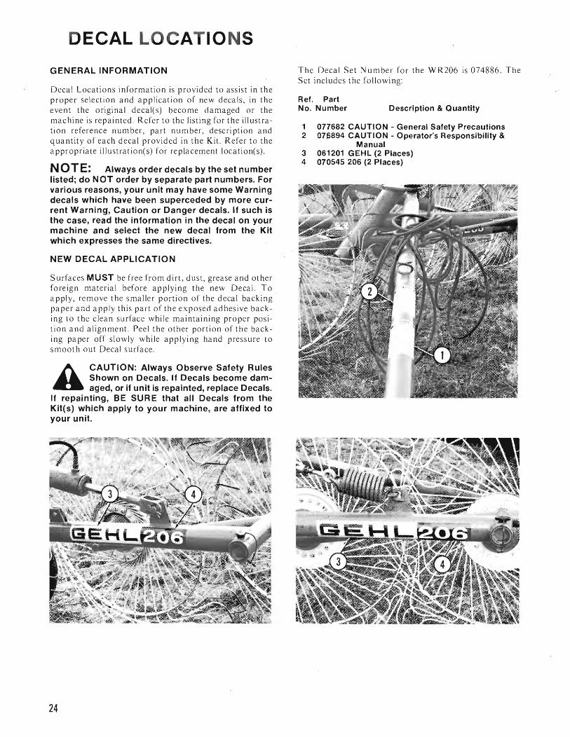
GENERAL INFORMATION
Decal Locations information is provided to assist in the proper selection and application of new decals, in the event the original decaJ(s) become damaged or the machine is repainted. Refer to the listing for the illustration reference number, part number, description and qua ntity of each decal provided in the Kit. Refer to the appropriate illustration(s) for replacement location(s) .
NOTE: Always order"decals by the set number listed; do NOT order by separate part numbers. For various reasons, your unit may have some Warning decals which have been superceded by more current Warning, Caution or Danger decals. If such is the case, read the information in the decal on your machine and select the new decal from the Kit which expresses the same directives.
NEW DECAL APPLICATION
Surfaces MUST be free from dirt, dust, grease and other foreign material before applying the new Decal. To apply, remove the smaller portion of the decal backing paper and apply this part of the exposed adhesive backing to the clean surface while maintaining proper position and alignment. Peel the other portion of the backing paper off slowly while applying hand pressure to smooth out Decal surface .
A CAUTION: Always Observe Safety ~ules Shown on Decals. If Decals become damaged, or if unit is repainted, replace Decals.
If repainting, BE SUR E that all Decals from the Kit(s) which apply to your machine, are affixed to your unit.
The Decal Set Number for the WR206 is 074886. The Set includes the followi ng:
Ref. Part No. Number Description & Quantity
1 077682 CAUTION - General Safety Precautions 2 07J)894 CAUTION - Operator's Responsibility &
Manual 3 061201 GEHL (2 Places) 4 070545 206 (2 Places)
24

~~~~~~~~~~~~~~~~R206 - NUMERICAL INDEX
PART PAGE REF. PART PAGE REF. PART PAGE REF. NO. NO. NO. NO. NO. NO. NO. NO. NO. NO. NO. NO.
071042 21 01
PART PAGE REF.
610465 21 20 520105 22 01 610469 23 21 604597 23 01 610471 21 21 604600 23 02 610489 22 11 604629 21 02 610491 23 22 604629 23 03 610886 22 12 604780 23 04 610887 22 13 604790 23 05 610895 22 14 604993 23 06 610896 22 15 604996 22 02 610897 22 16 604998 22 03 610898 22 17 604999 22 14 610899 22 18 610350 22 04 610900 21 22 610351 22 05 656006 22 19 610352 22 06 656008 22 20 610353 22 07 656009 23 23 610354 22 08 656029 23 24 610355 22 09 656049 22 21 610356 22 10 656049 23 25 610357 23 07 656052 21 23 610358 23 08 656059 23 26 610359 23 09 656071 21 24 610360 23 10 656074 23 27 610361 23 11 610362 23 12 610363 23 13 610364 23 14 610365 23 15 610366 23 16 610367 23 17 610368 23 18 610370 23 19 610371 21 03 610372 21 04 610373 21 05 610374 21 06 610375 21 07 610376 21 08 610377 21 09 610378 21 10
610379 21 11 610380 21 12 610381 21 13 610382 21 14 610383 21 15 610384 21 16 610385 21 17 610387 21 18 610388 21 22 610389 21 19 610453 23 20
25

NOTES
26
INDEX
Page Check Lists .................................. 5-7 Decal Locations .... . .......................... 24 General Information ......................... 9-18
Abbreviations ................................ 9 General Bolt Torque Data ..................... 9 Packing ..................................... 9 Tractor Provisions ............................ 9 Rake Assembly ................. . .......... 9-11 Finger Wheel Hubs .......................... 12 Finger Wheel Pressure Adjustment ............. 13 Working Width ........................... 14-15 General Operation ........................ 16-17 Transporting ............................. 17-18 Maintenance ................................ 18 Hard ware .................................. 18 Lubrication ................................ 18 Tires & Wheels ............................. 18
Introd uction ................................... 3 Numerical Index ............................... 25 Safety ....................... ; ................. 8 Service Parts ............................... 20-23
WR206 Frame ............................ 20-21 WR206 Finger Wheels ........................ 22 ' WR206 Wheels & Drawbar ................... 23
Specifications .................................. 4 Table of Contents ..................•............ 3 Warranty ...................................... 2
27
FARM EQUIPMENT GEHL COMPANY WEST BEND, WISCONSIN 53095 U.S.A.
903467/1P1184 Printed in U.S.A.