operator's guide and replacement parts list for the · pdf fileoperator's guide and...
TRANSCRIPT

Operator's Guide and Replacement Parts List for
the
A2500 MULTI-MOUNT
ATV WINCH
WARN INDUSTRIES, INC. * 12900 CAPPS ROAD * CLACKAMAS, OREGON 97015
(503)722-1200 * CUSTOMER SERVICE LINE 1-800-543-WARN * FAX (503)722-3000

SAFETY PRECAUTIONS
MOVING PART HAZARD TO PREVENT SERIOUS INJURY AND PROPERTY DAMAGE:
• Do not operate or install winch without reading andunderstanding the operators manual.
• Keep hands clear of wire rope, hook, and fairlead
opening during operation and when spooling. • Stand clear of wire rope and load during operation. • Keep others away. • Always inspect winch installation and wire rope
condition before operating winch. • Do not exceed winch rated capacity. • Never touch wire rope or hook while in tension.
PAGE 2

APPLICATION INFORMATION
TO PREVENT SERIOUS INJURY:• Do not use as a hoist.• Do not use to move persons.
DO NOT TIE-DOWN ATV DURING WINCH OPERATION.THIS MAY LEAD TO DAMAGE
TO THE ATV FRAME.
TO AVOID INJURY AND PROPERTY DAMAGE:• Do not use winch to secure a load during transport.• Do not submerge in water.• Do not use to tow other vehicles.
• Maximum single line pulling capacity : 2500 lb. (1100 kg). • Intermittent duty rating. • 12 Volts DC. • Use only 3/16" (4.8 mm) 7 x 19 aircraft wire rope.
PAGE 3
INSTALLATION INSTRUCTIONS STEP ONE - SAFETY FIRST When installing your ATV winch system, read and follow all mounting and safety instructions. Always use caution when working with electricity and remember to verify that no exposed electrical connections exist before energizing your winch circuit.
STEP TWO - WINCH MOUNTING ATV winch mounting kits are available from your Warn Dealer to satisfy nearly all ATV applications. For information on available kits, contact your Warn product dealer.
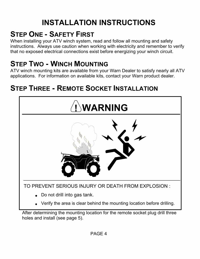
STEP THREE - REMOTE SOCKET INSTALLATION
After determining the mounting location for the remote socket plug drill three holes and install (see page 5).
PAGE 4
WARNING!
TO PREVENT SERIOUS INJURY OR DEATH FROM EXPLOSION :
• Do not drill into gas tank.
• Verify the area is clear behind the mounting location before drilling.
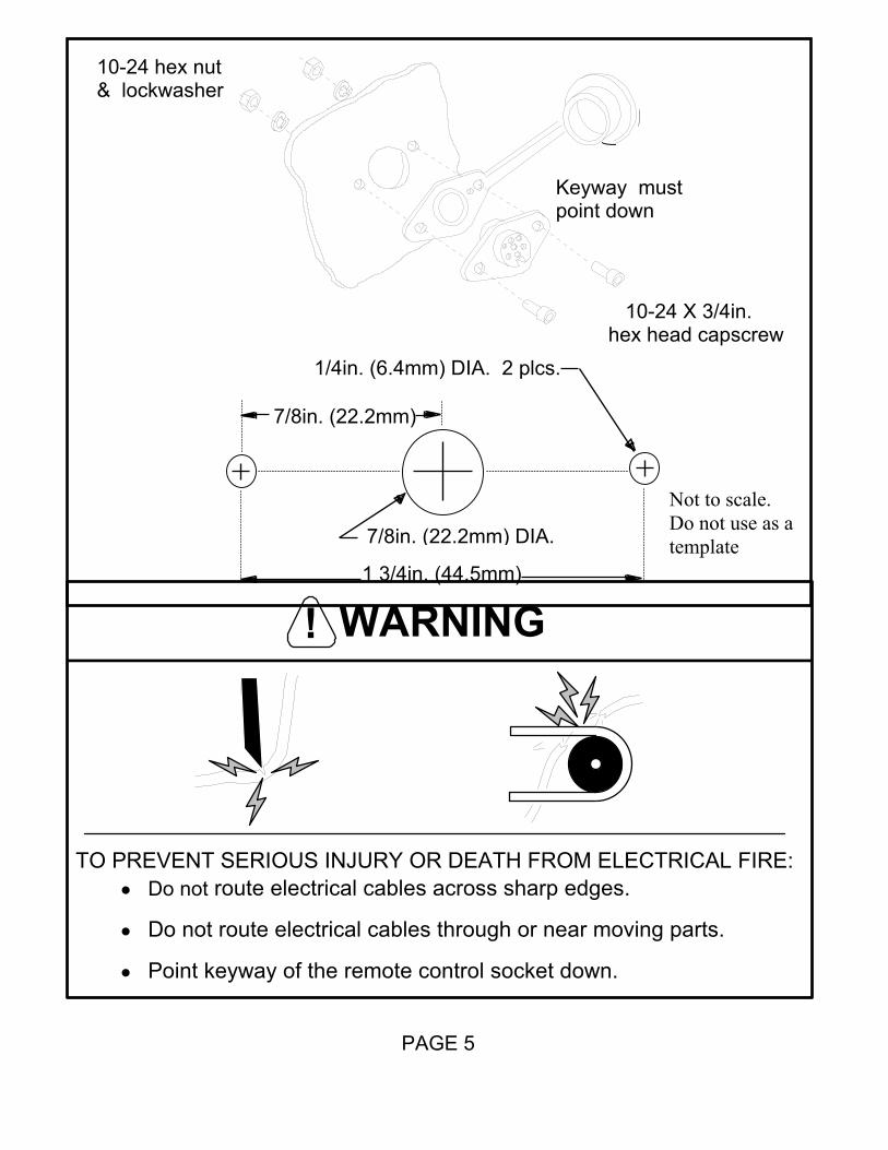
WARNING!
TO PREVENT SERIOUS INJURY OR DEATH FROM ELECTRICAL FIRE:• Do not route electrical cables across sharp edges.
• Do not route electrical cables through or near moving parts.
• Point keyway of the remote control socket down.
PAGE 5
1 3/4in. (44.5mm)
7/8in. (22.2mm) DIA.
1/4in. (6.4mm) DIA. 2 plcs.
7/8in. (22.2mm)
10-24 X 3/4in. hex head capscrew
10-24 hex nut & lockwasher
Keyway must point down
Not to scale. Do not use as a template

Once the remote socket is mounted, run the two male and female bullet type terminal wires up to where the solenoid will be mounted. Splice the end of the red 20ga wire to a key controlled electrical wire of the ATV. Using a test light, locate a suitable wire from the ATV key switch. The wire should only have power when the key is in the “ON” position.
PAGE 6
splice
ON
OFF
Test Light
red wire
To Motor Terminal #1 (Yellow)
96 in (.4mm) black wire
Key
To Motor Terminal #2 (blue)
96 in (.4mm) black wire
To Battery ( - ) (black)
36in (.92mm) black wire
To Battery ( + ) (red)
36in (.92mm) red wire
The quick disconnect terminals must be attached to the solenoid in a back to back configuration with one large boot covering both terminals.

STEP FOUR - SOLENOID INSTALLATION The solenoid is a primary safety feature in your winch system. Carefully follow the instructions for installation. The solenoid must be correctly installed to work properly. When attaching the wire terminals, always remember to use the terminal boots supplied with the winch kit.
• Attach the bullet terminals of the green and black remote socket wires to the bullet terminals of the solenoid as shown on page 6.
• Attach the 36in (.92m), 6ga red wire to the positive solenoid post (red post) and battery. Attach the 36in (.92m), 6ga black wire to the negative solenoid post (black post) and battery.
• Attach the two quick disconnects to the yellow solenoid post. Place the red wire from the 48 in. quick disconnect and the red wire from the 96 in. quick disconnect to the yellow post. Place the black wire from the 48 in. quick disconnect and the black wire from the 96 in. quick disconnect to the blue post (see page 6).
NOTE The flat side of the quick disconnect terminals must be back to back for
mounting to the solenoid.
STEP FIVE – Wiring the Motor • Attach the 21 in. quick disconnect to the motor. The terminal leads are
marked with the # 1 & # 2 to match the corresponding number on the motor.
PAGE 7
11
Blue post
Yellow post

STEP SIX – REMOTE CONTROL INSTALLATION
• It is recommended that the remote control holder be installed on the left handle bar. A piece of electrical tape around the handle bar will help prevent the holder from rotating around.
• Do not tighten over hoses or any cables.
• Place the remote into the holder and attach the strap.
• When the winch is not in use it is recommend that the remote control be unplugged and placed in the storage box.
PAGE 8
1/4 20 X 1 1/2 in. capscrew
1/4 - 20 locknut

STEP SEVEN - SYSTEM CHECK Before using the winch, verify the following:
• Wiring to all components is correct. All loose wires are tie wrapped tight.
• There are no exposed wiring or terminals, cover any existing exposures with terminal boots, heat shrink tubing or electricians tape.
• The solenoid is properly grounded.
• Turn ATV key switch to ON position. Check winch for proper operation.
IN OUT
CAUTION!KNOW YOUR WINCH: Take time to fully understandyour winch and the winching operation.
PAGE 9

OPERATING INSTRUCTIONS
CLUTCH OPERATION
Do not disengage clutch if winch is under load orwire rope is in tension.
TO PREVENT SERIOUS INJURY OR PROPERTY DAMAGE:
WARNING!
When the clutch is engaged the gear train is coupled to the wire rope drum and power may be transferred from the winch motor. When the clutch is in free spool the gear train and wire rope drum are uncoupled allowing the drum to rotate freely. The clutch knob, located on the winch housing opposite the motor, controls the clutch position. To prevent damage, always fully engage or fully disengage the clutch knob.
Engaged Freespool
Engage fullyuntil clutchknob “clicks”into place
OVERLOADING/OVERHEATING This winch is rated for intermittent duty. It should not be operated with the motor slowed down to a low RPM. When the motor approaches stall speed, a very rapid heat build-up occurs which may cause motor damage. To judge safe running time, stop winching and lay your hand on the motor. If the temperature is uncomfortable, shut down and cool the motor. This can be used as an opportunity to recharge the battery. Double line rigging will reduce the amperage draw from the motor allowing longer continual use (see rigging section).
PAGE 10

BATTERY RECOMMENDATIONS A fully charged battery and good connections are essential to the proper operation of your winch. The minimum requirements for a 12 volt DC battery is 12 AMP hours.
MAINTENANCE
• No lubrication is required for the life of the winch. • Check battery cables at 90 day intervals to be certain that they are clean and
tight at all connections. • Inspect the wire rope before and after each winching operation. Replace when
damaged. SPOOLING OUT Freespooling is generally the quickest and easiest way to spool out wire rope. Before freespooling wire rope out from the winch, power out enough rope to remove any tension the wire rope may be under before disengaging the clutch. Now freespool by manually spooling out enough wire rope for the winching operation.
TO AVOID INJURY AND PROPERTY DAMAGE:
• Wear heavy leather gloves when handling wire rope.
• Never winch with less than 5 wraps of wire rope arounddrum.
PAGE 11

STRETCHING THE WIRE ROPE
The life of a wire rope is directly related to the care and use it receives. During its first use, a new wire rope must be spooled onto its drum under a load of at least 500 lb. (227kg). Spool out the entire wire rope length leaving 5 wraps on the drum, then power in the wire rope under a load of 500 lb. (227kg) or more. This will stretch new wire rope and create a good wire wrap around the drum. Failure to do so may result in the outer wire wraps drawing into the inner wraps, binding, and damaging the wire rope.
TO PREVENT SERIOUS INJURY:
• Keep hands clear of wire rope, hook, and fairleadopening during operation.
• Always use the hook strap to hold hook whenspooling.
SPOOLING IN UNDER LOAD
• The wire rope must always spool onto the drum as indicated by the drum rotation decal on the winch.
• Power in the wire rope evenly and tightly on the drum. This prevents the outer wire wraps from drawing into the inner wraps, binding and damaging the wire rope.
• Avoid shock loads when spooling, by using the control switch intermittently to take up wire rope slack. Shock loads can momentarily far exceed the winch and wire rope ratings.
PAGE 12

SPOOLING IN UNDER NO LOAD
• Assisted: Have your assistant hold the hook with a cord or rag putting as much constant tension on the wire rope as possible. While keeping tension, the assistant should walk toward the winch while you operate the control switch spooling in the wire rope. Release the switch when the hook is a minimum of 4 ft (1.2m) from the fairlead opening. Spool in the remainder for storage.
• Unassisted: Arrange the wire rope to be spooled so it will not kink or tangle
when spooled. Be sure any wire rope on the drum is tightly and evenly layered. Spool enough wire rope to complete the next full layer on the drum. Tighten and straighten the layer. Repeat process until the hook is a minimum of 4ft (1.2m) from the fairlead. Spool in the remainder for storage.
SPOOLING REMAINDER FOR STORAGE
Keep hands clear of wire rope, hook, and fairlead opening. Always use the hook strap to hold the hook when spooling under no load. Carefully power in the remaining wire rope, jogging the control switch to take up the last of the slack. Secure the hook to a suitable anchor point near the winch. Be careful not to over tighten or damage may occur to the wire rope or anchor point.
RIGGING • Always spool out as much wire rope as possible when preparing rigging. Pick an
anchor as far away as is practical; this provides the winch with its greatest pulling power.
• Rigging a double line with a snatch block will reduce the load on the winch to half
without significant loss of spooling speed.
• Natural anchors such as trees, stumps and rocks are the handiest when available. Attach the choker chain, wire choker rope or tree trunk protector on the anchor as low as possible to avoid pulling the anchor down. If several possible anchors are available but they are not strong enough individually, it may be practical to attach a wire or chain choker around several anchors to form a strong collective anchor point.
• When using a double line pull, do not attach the hook to the winch-carrier plate.
Only attach the hook to the hook anchor loop (see page 15).
PAGE 13

TO PREVENT SERIOUS INJURY:
• Stand clear of wire rope and load during operation.
• Be certian the anchor will withstand the load.
• Always use a choker chain, wire choker rope, or tree trunk protector on the anchor.
• Take your time, sloppy rigging causes accidents.
• Approximate pulling power: Pulling Power Wire Rope Layer 2500 lb. (1134kg) 1st layer closest to drum core 2200 lb. (998kg) 2nd layer 1930 lb. (875kg) 3rd layer 1700 lb. (771kg) 4th layer
• Some of the most commonly used riggings are shown on page 15.
PAGE 14

PAGE 15
Single Line Pull
Double Line Pull Tree trunk protector
Snatch block
Direction Change Pull

Service Should you encounter a problem during installation or operation of your winch, please follow these steps toward resolving the problem:
1. Refer to your operator’s guide and installation instructions. It has illustrations and detailed information on the installation and safe and proper operation of your winch. It also includes a replacement parts list and assembly diagrams. If you are unable to resolve the problem, then go to step 2.
2. Contact your dealer where you purchased your winch. If, after discussing the problem
with their parts and service staff, you are still unable to resolve the problem then go to step 3.
3. Call an Authorized Warn Service Center from the list provided on the back of the
warranty sheet included with the product. When calling, please have the following information available: winch model number and purchase date, make, model & year of ATV.
4. If you are unable to resolve the problem to your satisfaction, please call Warn Industries
customer service at 1-800-543-9276. When calling, please have the following information available: winch model number and purchase date; make, model & year of ATV. You may also contact Warn by visiting our website www.warn.com.
WARRANTY Please refer to the warranty sheet enclosed with your winch for details.
PAGE 16

WARN A2500 ATV WINCH
REPLACEMENT PARTS LIST
ORDERING INFORMATION: Parts may be obtained through your local dealer or distributor. ITEM QTY NUMBER DESCRIPTION 1 1 36030 Endhousing, Clutch assy (includes items 3 & 4) 2 4 7953 Square Nut 3 1 21872 Cam Follower 4 1 21895 Thrust Plate 5 1 21292 Sun Gear, Stage 2 6 1 21329 Carrier Assy., Stage 2 7 1 21330 Carrier Assy., Stage 3 8 2 21665 Drum Support 9 2 21296 Drum Bushing 9 2 21597 Drum Support with Bushing 10 1 25257 Cable Protector 11 1 60078 Drum Assy (no wire rope) 11 1 39315 Drum Assy 12 1 60076 Wire Rope Assy., 3/16” x 50’ 13 2 21268 Tie Rod 14 1 34797 Drive Shaft 16 1 21883 Clutch Return Spring 17 1 21320 Carrier Assy., Stage 1 18 1 21290 Sun Gear, Stage 1 19 1 36054 Endhousing, Motor assy (includes part # 35033 & 21316) 20 4 8956 Socket Head Capscrew 1/4-20 X 1/2 21 4 1936 Socket Head Capscrew 1/4-20 X 5/8 22 1 21594 Armature, 12 VDC Motor 23 1 36031 Motor, 12 VDC 24 1 31928 Cap assy, 12 VDC Motor 25 4 2090 Boot, Electric terminal 26 1 62135 Contactor 27 1 62259 Cable, 6ga Black 36” 27 1 62263 Cable, 6ga Red 36” 28 2 32615 10-24 X 3/4 Machine Screw 28 2 2546 10-24 Nut 29 1 37677 Remote 30 1 60924 Wiring, Winch-Carrier 31 1 37674 Strap 32 1 2514 1/4-20 X 1.5 Capscrew 33 1 37676 Remote Holster 34 1 21842 Splice, 20 GA 35 1 62258 Remote Control, Socket 36 1 62261 Wiring Assy, Front-MM, 96" 36 1 62260 Wiring Assy, Rear-MM, 48" 37 1 60917 Dust Cover 38 1 60910 Carrier Plate, Winch 39 1 28722 Roller Fairlead 40 2 2228 3/8-16 X .75 Capscrew 40 2 1829 3/8 Lockwasher 40 2 2317 3/8-16 Nut 41 1 39557 Hook, 5/16 Clevis Slip w/ Strap 42 1 38293 Strap, Hook 43 4 1402 5/16 Lockwasher 43 4 21331 5/16-18 Hex Head Capscrew 44 1 27960 Receiver Pin 44 1 27961 Receiver Clip
PAGE 17

PARTS BREAKDOWN
PAGE 18

PAGE 19

PAGE 20

PAGE 21

PN 60908 REV. C1
© 2005 Copyright Warn Industries, Inc. All rights reserved.