operator's manual 115h - pdf.lowes.com
TRANSCRIPT
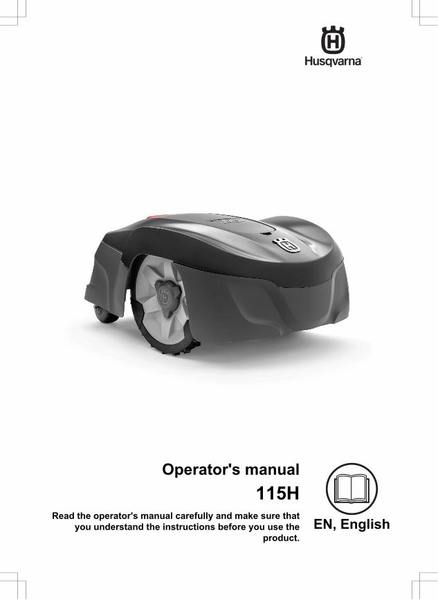
EN, English
Operator's manual115H
Read the operator's manual carefully and make sure thatyou understand the instructions before you use the
product.
Contents
1 Introduction1.1 Introduction.................................................31.2 Product overview........................................41.3 Symbols on the product..............................51.4 Symbols on the display.............................. 51.5 Symbols on the battery...............................51.6 Menu structure overview............................ 71.7 Display........................................................81.8 Keypad ...................................................... 8
2 Safety2.1 Safety definitions........................................ 92.2 General safety instructions.........................92.3 Safety instructions for operation...............11
3 Installation3.1 Introduction - Installation.......................... 143.2 Before the installation of the wires........... 143.3 Before the installation of the product........143.4 Installation of the product......................... 183.5 To put the wire into position with stakes...193.6 To bury the boundary wire or theguide wire....................................................... 193.7 To change the position of theboundary wire or the guide wire..................... 193.8 To extend the boundary wire or theguide wire....................................................... 193.9 After the installation of the product...........203.10 To do the product settings......................20
4 Operation4.1 The ON/OFF button..................................264.2 To start the product.................................. 264.3 Operating modes......................................264.4 Stop.......................................................... 274.5 Switch off..................................................274.6 To charge the battery............................... 284.7 Adjust the cutting height........................... 28
5 Maintenance5.1 Introduction - maintenance.......................295.2 Clean the product..................................... 295.3 Replace the blades...................................305.4 Software update....................................... 305.5 Battery...................................................... 315.6 Winter service...........................................32
6 Troubleshooting
6.1 Introduction - troubleshooting...................336.2 Fault messages........................................ 346.3 Information messages.............................. 386.4 Indicator lamp in the charging station.......396.5 Symptoms................................................ 406.6 Find breaks in the loop wire..................... 41
7 Transportation, storage and disposal7.1 Transportation.......................................... 447.2 Storage.....................................................447.3 Disposal....................................................44
8 Technical data8.1 Technical data.......................................... 45
9 Warranty9.1 Guarantee terms...................................... 47
10 Applicable to US/CA market10.1 Supplier's Declaration of Conformity...... 4810.2 Compliance requirements...................... 48
2 982 - 001 - 12.12.2018

1 Introduction
1.1 IntroductionSerial number:
PIN code:
Product registration key:
The serial number is on the product rating plate and on the product carton.• Use the serial number to register your product on www.husqvarna.com.
1.1.1 SupportFor support about the Husqvarna product, speakto your servicing dealer.
1.1.2 Product descriptionNote: Husqvarna regularly updates theappearance and function of the products. Referto Support on page 3.
The product is a robotic lawn mower. The producthas a battery power source and cuts the grass
automatically. Collection of grass is notnecessary.
The operator selects the operation settings withthe keys on the keypad. The display shows theselected and possible operation settings, and theoperation mode of the product.
The boundary wire and the guide wire controlsthe movement of the product within the workarea.
982 - 001 - 12.12.2018 Introduction - 3

1.2 Product overview
OK
OK
11
13
12
6
1617
15
14
18
10
9
24
19
26
20
22
2321
25 27
7
8
1
23
5
4
The numbers in the figure represent:
1. Body2. Hatch to display and keypad3. Stop button4. Rear wheels5. Front wheels6. Charging station7. Contact strips8. LED for operation check of the charging
station, boundary wire and guide wire9. Cutting height adjustment10. Rating plate11. Display12. Keypad13. ON/OFF button14. Cutting system15. Blade disc
16. Handle17. Chassis box with electronics, battery and
motors18. Battery cover19. Power supply (the appearance of the power
supply may differ depending on market)20. Stakes21. Measurement gauge for help when installing
the boundary wire (the measurement gaugeis broken loose from the box)
22. Connector for the loop wire23. Screws for securing the charging station24. Couplers for loop wire25. Low voltage cable26. Loop wire for boundary loop and guide wire27. Operator’s Manual and Quick Guide
4 - Introduction 982 - 001 - 12.12.2018
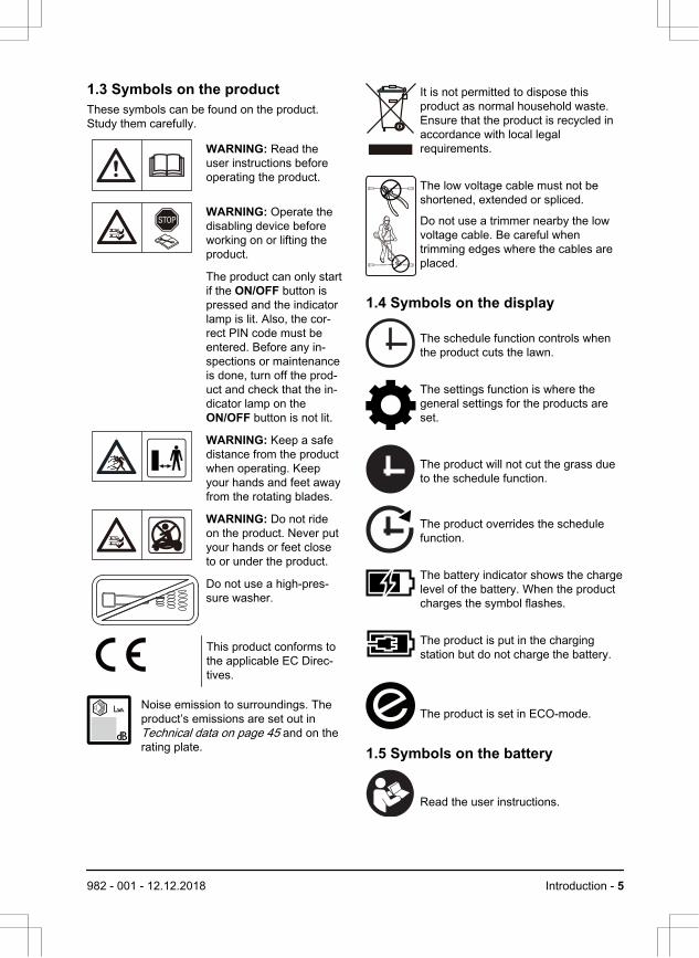
1.3 Symbols on the productThese symbols can be found on the product.Study them carefully.
WARNING: Read theuser instructions beforeoperating the product.
WARNING: Operate thedisabling device beforeworking on or lifting theproduct.
The product can only startif the ON/OFF button ispressed and the indicatorlamp is lit. Also, the cor-rect PIN code must beentered. Before any in-spections or maintenanceis done, turn off the prod-uct and check that the in-dicator lamp on theON/OFF button is not lit.
WARNING: Keep a safedistance from the productwhen operating. Keepyour hands and feet awayfrom the rotating blades.
WARNING: Do not rideon the product. Never putyour hands or feet closeto or under the product.
Do not use a high-pres-sure washer.
This product conforms tothe applicable EC Direc-tives.
Noise emission to surroundings. Theproduct’s emissions are set out in Technical data on page 45 and on therating plate.
It is not permitted to dispose thisproduct as normal household waste.Ensure that the product is recycled inaccordance with local legalrequirements.
The low voltage cable must not beshortened, extended or spliced.
Do not use a trimmer nearby the lowvoltage cable. Be careful whentrimming edges where the cables areplaced.
1.4 Symbols on the display
The schedule function controls whenthe product cuts the lawn.
The settings function is where thegeneral settings for the products areset.
The product will not cut the grass dueto the schedule function.
The product overrides the schedulefunction.
The battery indicator shows the chargelevel of the battery. When the productcharges the symbol flashes.
The product is put in the chargingstation but do not charge the battery.
The product is set in ECO-mode.
1.5 Symbols on the battery
Read the user instructions.
982 - 001 - 12.12.2018 Introduction - 5

Do not discard the battery into fire anddo not expose the battery to a heatsource. Do not immerse the battery into water.
6 - Introduction 982 - 001 - 12.12.2018

1.6 Menu structure overview
Schedule
Overview week
Period 1 Period 2 Copy
Su Current
day
All weekSaFrThWeTuMoAll
days
Reset
Wizard Advanced
Settings
Time &
date
Set time Set date Time format Date format
Language Country Reset all
user setting
About
Security Lawn Coverage Installation General
Low Medium
Change
PIN code
New loop
signal
Security level Advanced
Area 1-3
How? How
often?
How
far?
Disable
ResetTest
More
Starting
point
Drive Past
Wire
ECO
mode
Mower
house
High
Connect@Home
New
pairing
Remove
paired
devices
982 - 001 - 12.12.2018 Introduction - 7

1.7 DisplayThe display on the product shows informationand settings of the product.
To access the display, push the STOP button.
1.8 Keypad The keypad consists of 6 groups of buttons:
OK
1
2
3
5
4
6
1. The ON/OFF button is used to turn theproduct ON/OFF. The indicator lamp on theON/OFF button is an important statusindicator. Refer to The indicator lamp onpage 26.
2. The Start button is used to start theoperation of the product.
3. The Menu button is used to go to the mainmenu.Note: The Menu button is also used as aBack button, that is, when moving back upin the menu lists.
4. The Mode button is used to chooseoperating mode, for example, Main area orPark.
5. The OK button is used to confirm thechosen settings in the menus.
6. The arrow keys are used to navigate in themenu. The up/down arrow keys are alsoused to enter digits, for example, PIN code,time and date
8 - Introduction 982 - 001 - 12.12.2018

2 Safety2.1 Safety definitionsWarnings, cautions and notes are used to pointout specially important parts of the manual.
WARNING: Used if there is a risk ofinjury or death for the operator orbystanders if the instructions in themanual are not obeyed.
CAUTION: Used if there is a risk ofdamage to the product, other materialsor the adjacent area if the instructionsin the manual are not obeyed.
Note: Used to give more information that isnecessary in a given situation.
2.2 General safety instructionsThe following system is used in the Operator’sManual to make it easier to use:
• Text written in italics is a text that is shownon the display of the product or is areference to another section in theOperator’s Manual.
• Text written in bold is one of the buttons onthe keypad of the product.
• Text written in UPPERCASE and italics referto the different operating modes available inthe product.
982 - 001 - 12.12.2018 Safety - 9

2.2.1 IMPORTANT. READ CAREFULLYBEFORE USE. KEEP FOR FUTUREREFERENCEThe operator is responsible for accidents or hazards occurring toother people or property.This appliance is not intended for use by persons (including chil-dren) with reduced physical, sensory or mental capabilities (thatcould affect a safe handling of the product), or lack of experienceand knowledge, unless they have been given supervision or in-struction concerning use of the appliance by a person responsiblefor their safety.This appliance can be used by children aged from 8 years andabove and persons with reduced physical, sensory or mental ca-pabilities or lack of experience and knowledge if they have beengiven supervision or instruction concerning use of the appliance ina safe way and understand the hazards involved. Local regula-tions may restrict the age of the operator. Cleaning and mainte-nance shall not be made by children without supervision.Never connect the power supply to an outlet if the plug or cord isdamaged. Worn or damaged cord increase the risk of electricshock.Only charge the battery in the included charging station. Incorrectuse may result in electric shock, overheating or leaking of corro-sive liquid from the battery. In the event of leakage of electrolyte,flush with water/neutralizing agent. Seek medical help if it comesin contact with the eyes.Use only original batteries recommended by the manufacturer.Product safety cannot be guaranteed with other than original bat-teries. Do not use non-rechargeable batteries.The appliance must be disconnected from the supply mains whenremoving the battery.
10 - Safety 982 - 001 - 12.12.2018

WARNING: The productcan be dangerous if usedincorrectly.
WARNING: Do not usethe product whenpersons, especiallychildren, or animals, arein the work area.
WARNING: Keep yourhands and feet awayfrom the rotating blades.Never put your hands orfeet close to or under theproduct when the motoris running.
2.3 Safety instructions for operation2.3.1 Use• The product is designed to mow grass in
open and level ground areas. It may only beused with the equipment recommended bythe manufacturer. All other types of use areincorrect. The manufacturer’s instructionswith regard to operation/maintenance mustbe followed precisely.
• Warning signs shall be placed around thework area of the product if it is used in publicareas. The signs shall have the followingtext: Warning! Automatic lawnmower!Keep away from the machine! Supervisechildren!
Warning!Automatic lawnmower!
Keep away from the machine!Supervise children!
Warning!
Automatic lawnmower!
Keep away from the machine!
Supervise children!
• Use the operating mode Park or turn off theproduct when persons, especially children,or animals, are in the work area. It isrecommended to program the product foruse during hours when the area is free fromactivity, e.g. at night. Refer to To set theschedule on page 21. Consider that certainspecies, e.g. hedgehogs, are active at night.They can potentially be harmed by theproduct.
• The product may only be operated,maintained and repaired by persons that arefully conversant with its specialcharacteristics and safety regulations.Please read the Operator’s Manual carefullyand make sure you understand theinstructions before using the product.
• It is not permitted to modify the originaldesign of the product. All modifications aremade at your own risk.
• Check that there are no stones, branches,tools, toys or other objects on the lawn thatcan damage the blades. Objects on the lawncan also lead to the product getting stuck.Help may be required to remove the objectbefore the product can continue mowing.Always turn off the product using theON/OFF button before clearing a blockage.
982 - 001 - 12.12.2018 Safety - 11

• Start the product according to theinstructions. When the product is turned on,make sure to keep your hands and feetaway from the rotating blades. Never putyour hands and feet under the product.
• Never touch moving hazardous parts, suchas the blade disc, before it has come to acomplete stop.
• Never lift up the product or carry it aroundwhen it is turned on.
• Do not let persons who do not know how theproduct works and behaves use it.
• The product must never be allowed tocollide with persons or other living creatures.If a person or other living creature comes inthe product’s way it shall be stoppedimmediately. Refer to Stop on page 27.
• Do not put anything on top of the product orits charging station.
• Do not allow the product to be used with adefective guard, blade disc or body. Neithershould it be used with defective blades,screws, nuts or cables. Never connect adamaged cable, or touch a damaged cablebefore it is disconnected from the supply.
• Do not use the product if the ON/OFF buttondoes not work.
• Always switch off the product using theON/OFF button when the product is not inuse. The product can only start when theON/OFF button has been turned on and thecorrect PIN code has been entered.
• HUSQVARNA does not guarantee fullcompatibility between the product and othertypes of wireless systems such as remotecontrols, radio transmitters, hearing loops,underground electric animal fencing orsimilar.
• Metal objects in the ground (for examplereinforced concrete or anti-mole nets) canresult in a stoppage. The metal objects cancause interference with the loop signalwhich then can lead to a stoppage.
• Operation and storage temperature is 0-50°C / 32-122 °F. Temperature range forcharging is 0-45 °C / 32-113 °F. Too hightemperatures might cause damage to theproduct.
2.3.2 Battery safetyWARNING: Lithium-ion batteries canexplode or cause fire if disassembled,short-circuited, exposed to water, fire,or high temperatures. Handle carefully,do not dismantle, open the battery oruse any type of electrical/mechanicalabuse. Avoid storage in direct sunlight.
For more information about the battery, refer to Battery on page 31
2.3.3 How to lift and move the productTo safely move from or within the work area:
1. Press the STOP button to stop the product.If security is set to high level (refer to To setthe security level on page 22) the PIN codehas to be entered. The PIN code containsfour digits and is selected when you start theproduct for the first time. Refer to To do thebasic settings on page 20.
2. Press the ON/OFF button and make surethe product is turned off. Check that theindicator lamp on the ON/OFF button is notlit. This means that the product is disabled.Refer to The indicator lamp on page 26.
12 - Safety 982 - 001 - 12.12.2018

OK
OKOK
3. Carry the product by the handle with theblade disc away from the body.
WARNING: The product must beturned off before lifting it. The productis disabled when the indicator lamp onthe ON/OFF button is not lit.
CAUTION: Do not lift the product whenit is parked in the charging station. Itcan damage the charging stationand/or the product. Press STOP andpull the product out of the chargingstation before lifting it.
2.3.4 MaintenanceWARNING: The product must beturned off before any maintenance isdone. The product is disabled whenthe indicator lamp on the ON/OFFbutton is not lit.
OK
OKOK
CAUTION: Never use a high-pressurewasher to clean the product. Neveruse solvents for cleaning.
Inspect the product weekly and replace anydamaged or worn parts. Refer to Introduction -maintenance on page 29.
2.3.5 In the event of a thunderstorm
To reduce the risk of damage to electricalcomponents in the product and the chargingstation, we recommend that all connections to thecharging station are disconnected (power supply,boundary wire and guide wire) if there is a risk ofa thunderstorm.
1. Mark the wires to simplify reconnecting. Thecharging station’s connections are markedR, L and GUIDE.
2. Disconnect all connected wires and thepower supply.
3. Connect all the wires and the power supplyif there is no longer a risk of thunder. It isimportant that each wire is connected to theright place.
982 - 001 - 12.12.2018 Safety - 13
3 Installation3.1 Introduction - Installation
WARNING: Read and understand thesafety chapter before you install theproduct.
CAUTION: Only use original spareparts and installation material.
Note: Refer to www.husqvarna.com for moreinformation about installation.
3.2 Before the installation of thewiresYou can select to attach the wires with stakes orbury them. You can use the 2 procedures for thesame work area.
• Bury the boundary wire or the guide wire ifyou are going to use a dethatcher on thework area. If not, attach the boundary wireor guide wire with stakes.
• Cut the grass before you install the product.Make sure that the grass is maximum 4 cm /1.6 in.
Note: The first weeks after installation theperceived sound level when cutting the grassmay be higher than expected. When the producthas cut the grass for some time, the perceivedsound level is much lower.
3.3 Before the installation of theproduct• Make a blueprint of the work area and
include all obstacles.• Make a mark on the blueprint where to put
the charging station, the boundary wire andthe guide wire.
• Make a mark on the blueprint where theguide wire connects to the boundary wire.Refer to To install the guide wire on page18.
• Fill in holes in the lawn.
Note: Holes with water in the lawn cancause damage to the product.
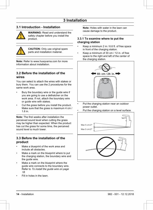
3.3.1 To examine where to put thecharging station• Keep a minimum 2 m / 6.6 ft. of free space
in front of the charging station.• Keep a minimum of 30 cm / 12 in. of free
space to the right and left of the center ofthe charging station.
60- cm / 24- in.
• Put the charging station near an outdoorpower outlet.
• Put the charging station on a level surface.
Max 5 cm/2"
Max 5 cm/2"
14 - Installation 982 - 001 - 12.12.2018
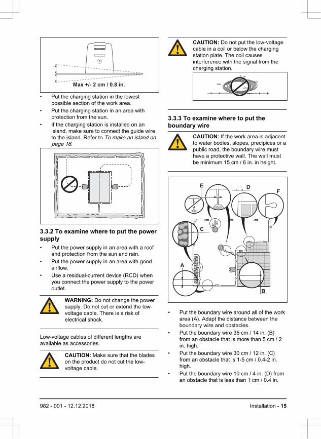
Max +/- 2 cm / 0.8 in.
• Put the charging station in the lowestpossible section of the work area.
• Put the charging station in an area withprotection from the sun.
• If the charging station is installed on anisland, make sure to connect the guide wireto the island. Refer to To make an island onpage 16.
3.3.2 To examine where to put the powersupply• Put the power supply in an area with a roof
and protection from the sun and rain.• Put the power supply in an area with good
airflow.• Use a residual-current device (RCD) when
you connect the power supply to the poweroutlet.
WARNING: Do not change the powersupply. Do not cut or extend the low-voltage cable. There is a risk ofelectrical shock.
Low-voltage cables of different lengths areavailable as accessories.
CAUTION: Make sure that the bladeson the product do not cut the low-voltage cable.
CAUTION: Do not put the low-voltagecable in a coil or below the chargingstation plate. The coil causesinterference with the signal from thecharging station.
3.3.3 To examine where to put theboundary wire
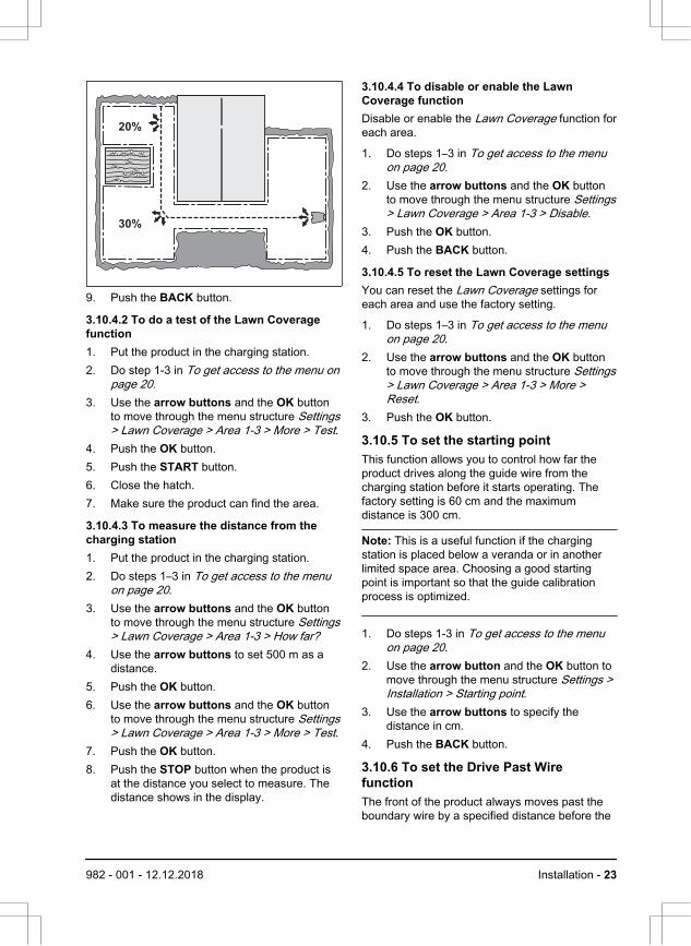
CAUTION: If the work area is adjacentto water bodies, slopes, precipices or apublic road, the boundary wire musthave a protective wall. The wall mustbe minimum 15 cm / 6 in. in height.
DE
B
C
F
A
• Put the boundary wire around all of the workarea (A). Adapt the distance between theboundary wire and obstacles.
• Put the boundary wire 35 cm / 14 in. (B)from an obstacle that is more than 5 cm / 2in. high.
• Put the boundary wire 30 cm / 12 in. (C)from an obstacle that is 1-5 cm / 0.4-2 in.high.
• Put the boundary wire 10 cm / 4 in. (D) froman obstacle that is less than 1 cm / 0.4 in.
982 - 001 - 12.12.2018 Installation - 15

• If you have a paving stone path that is inlevel with the lawn, put the boundary wirebelow the paving stone.
Note: If the paving stone is minimum 30cm / 12 in. wide, use the factory setting forthe Drive Past Wire function to cut all thegrass adjacent to the paving stone.
CAUTION: Do not let the productoperate on gravel.
• If you make an island, put the boundary wirethat runs to and from the island neartogether (E). Put the wires in the samestake.
• Make an eyelet (F) where the guide wire isto be connected to the boundary wire.
CAUTION: Do not make sharpbends when you install theboundary wire.
CAUTION: For careful operationwithout noise, isolate all obstaclessuch as trees, roots and stones.
3.3.3.1 To put the boundary wire in a slope• For slopes steeper than 30% inside the work
area, isolate the slope with boundary wire.• For slopes steeper than 15% along the outer
edge of the lawn, put the boundary wire 20cm / 8 in. (A) from the edge.
• For slopes adjacent to a public road, put afence or a protective wall along the outeredge of the slope.
A
>15% 0-30%
3.3.3.2 PassagesA passage is a section that has boundary wire oneach side and that connects 2 work areas. The
passage must be a minimum of 60 cm / 24 in.wide.
Note: If a passage is less than 2 m / 6.5 ft. wide,install a guide wire through the passage.
3.3.3.3 To make an island• Put the boundary wire to and around the
obstacle to make an island.• Put the 2 sections of boundary wire that run
to and from the obstacle together.• Put the 2 sections of boundary wire in the
same stake.
0 cm / 0"
CAUTION: Do not put a section ofboundary wire across the other.The sections of boundary wiremust be parallel.
CAUTION: Do not put the guidewire across the boundary wire, forexample a boundary wire thatgoes to an island.
16 - Installation 982 - 001 - 12.12.2018

3.3.3.4 To make a secondary areaMake a secondary area if the work area has 2areas that are not connected with a passage.
• Put the boundary wire around the secondaryarea (B) to make an island. The work areawith the charging station is the main area(A). Refer to To make an island on page 16.
B
A
Note: When the product cuts grass in thesecondary area, the Secondary area modemust be selected. Refer to 2nd area on page27.
3.3.4 To examine where to put the guidewire• Put the guide wire in a line at a minimum of
1 m / 3.3 ft. in front of the charging station.
Min 1m / 3.3ft
G
• Make sure that the guide wire has as muchfree area as possible to the left of the guidewire when facing the charging station. Referto Guide calibration on page 20.
• Put the guide wire minimum 30 cm / 12 in.from the boundary wire.
• Do not make sharp bends when you installthe guide wire.
• If the work area has a slope, put the guidewire diagonally across the slope.
3.3.5 Work area examples
B
D
A
C
• If the charging station is put in a small area(A), make sure that the distance to theboundary wire is at a minimum 2 m / 6.6 ft.
• If the work area has a passage (B), makesure that the distance to the boundary wireis at a minimum 2 m / 6.5 ft. If the passage issmaller than 2 m / 6.5 ft., install a guide wirethrough the passage. Minimum passagebetween the boundary wire is 60 cm / 24 in.
• If the work area has areas which areconnected by small passages (C), you canchange the settings in Lawn Coverage.Refer to To set the Lawn Coverage functionon page 22.
• If the work area includes a secondary area(D), refer to To make a secondary area onpage 17. Put the product in the secondaryarea and select Secondary area mode.
982 - 001 - 12.12.2018 Installation - 17

3.4 Installation of the product3.4.1 To install the charging station
WARNING: Obey national regulationsabout electrical safety.
1. Read and understand the instructions aboutthe charging station. Refer to To examinewhere to put the charging station on page14.
2. Put the charging station in the selected area.3. Connect the low-voltage cable to the
charging station.4. Put the power supply at a minimum height of
30 cm / 12 in.
min 30 cm / 12”
WARNING: Do not put the powersupply at a height where there is arisk it can be put in water. Do notput the power supply on theground.
5. Connect the power supply cable to a100-240V outdoor power outlet.
WARNING: Applicable to USA/Canada. If power supply isinstalled outdoors: Risk of ElectricShock. Install only to a coveredClass A GFCI receptacle (RCD)that has an enclosure that isweatherproof with the attachmentplug cap inserted or removed.
6. Attach the low-voltage cable in the groundwith stakes or bury the cable. Refer to Toput the wire into position with stakes onpage 19 or To bury the boundary wire orthe guide wire on page 19.
7. Connect the wires to the charging station.Refer to To install the boundary wire on
page 18 and To install the guide wire onpage 18.
8. Attach the charging station to the groundwith the supplied screws.
CAUTION: Do not make newholes in the charging station plate.
CAUTION: Do not put your feeton the charging station.
3.4.2 To install the boundary wire1. Put the boundary wire around all of the work
area. Start and complete the installationbehind the charging station.
CAUTION: Do not put unwantedwire in a coil. The coil causesinterference with the product.
2. Open the connector and put the boundarywire in the connector.
3. Close the connector with a pair of pliers.4. Cut the boundary wire 1-2 cm / 0.4-0.8 in.
above each connector.5. Push the right connector onto the metal pin
with the mark "R".6. Push the left connector onto the metal pin
with the mark "L".
3.4.3 To install the guide wire1. Open the connector and put the wire in the
connector.2. Close the connector with a pair of pliers.3. Cut the guide wire 1-2 cm / 0.4-0.8 in. above
each connector.4. Push the guide wire through the slot in the
charging station plate.5. Push the connector onto the metal pin with
the mark "G".
18 - Installation 982 - 001 - 12.12.2018

6. Put the end of the guide wire at the eyeleton the boundary wire.
7. Cut the boundary wire with a pair of wirecutters.
8. Connect the guide wire to the boundary wirewith a coupler.
a) Put the 2 ends of the boundary wireand the end of the guide wire into thecoupler.
Note: Make sure that you can see theend of the guide wire through thetransparent area of the coupler.
b) Push the button on the coupler with anadjustable pliers.
CAUTION: Twinned cables,or a screw terminal block thatis insulated with insulationtape are not satisfactorysplices. Soil moisture willcause the wire to oxidize andafter a time result in a brokencircuit.
9. Attach the guide wire to the ground. Withstakes or bury the guide wire in the ground.Refer to To put the wire into position withstakes on page 19 or To bury the boundarywire or the guide wire on page 19.
3.5 To put the wire into position withstakes• Put the boundary wire and the guide wire on
the ground.• Put the stakes at a minimum of 75 cm / 30
in. distance from each other.• Attach the stakes to the ground with a
hammer or a plastic mallet.
CAUTION: Make sure that thestakes hold the boundary wire andthe guide wire against the ground.
Note: The wire is overgrown with grass and notvisible after a few weeks.
3.6 To bury the boundary wire or theguide wire• Cut a groove in the ground with an edge
cutter or a straight shovel.• Put the boundary wire or the guide wire 1-20
cm / 0.4-8 in. into the ground.
3.7 To change the position of theboundary wire or the guide wire1. If the boundary wire or the guide wire is put
into position with stakes, remove the stakesfrom the ground.
2. Carefully remove the boundary wire or theguide wire from the ground.
3. Adjust the boundary wire or the guide wireinto a new position.
4. Put the boundary wire or the guide wire intoposition. Refer to To put the wire intoposition with stakes on page 19 or To burythe boundary wire or the guide wire on page19.
3.8 To extend the boundary wire orthe guide wireNote: Extend the boundary wire or the guide wireif it is too short for the work area. Use originalspare parts, for example couplers.
1. Cut the boundary wire or the guide wire witha pair of wire cutters where it is necessary toinstall the extension.
2. Add wire where it is necessary to install theextension.
3. Put the boundary wire or the guide wire intoposition.
4. Put the wire ends into a coupler.
982 - 001 - 12.12.2018 Installation - 19
Note: Make sure that you can see the endsof the boundary wire or the guide wirethrough the transparent area of the coupler.
5. Push the button on the coupler with anadjustable pliers.
3.9 After the installation of theproduct3.9.1 To do a visual check of thecharging station1. Make sure that the indicator LED lamp on
the charging station has a green light.2. If the indicator LED lamp does not have a
green light, do a check of the installation.Refer to Indicator lamp in the chargingstation on page 39 and To install thecharging station on page 18.
3.9.2 To do the basic settingsBefore you start the product for the first time, youmust do the basic settings and calibrate theproduct.
1. Push the ON/OFF button.2. Push the arrow buttons and the OK button.
Select language, country, date, time and seta PIN code.
Note: It is not possible to use 0000 as PINcode.
3. Put the product in the charging station.4. Push the START button and close the
hatch.
3.9.3 Guide calibrationThe calibration process sets as wide guidecorridor as possible to reduce the risk of tracks
forming on the lawn. Refer to To set the startingpoint on page 23.
Note: The product always runs to the left of theguide wire (as seen facing the charging station).
If the distance on the left side of the starting pointis less than 0.6 m / 2 ft. the calibration process isinterrupted. For the widest possible guidecorridor, make sure that the distance from thestarting point to the boundary wire is minimum1.35 m / 4.5 ft. (perpendicular to the guide wire).
3.10 To do the product settingsThe product has factory settings but the settingscan be adapted to each work area.
3.10.1 To get access to the menu1. Push the STOP button.2. Use the up/down arrow buttons and the
OK button to enter the PIN code.3. Push the MENU button.
3.10.2 To do the schedule settings
3.10.2.1 WizardThe wizard is a quick tool to find suitableschedule settings for your lawn.
1. Enter your estimated lawn size. It is notpossible to enter a larger lawn size than themaximum work capacity.
2. Push the OK button to confirm the lawn size.By entering your lawn size the wizardsuggests either a suitable daily schedule (goto step 4) or need input for inactive days.
3. Choose what day(s) the product should beinactive. Use the up/down arrow buttons toshift between days.
20 - Installation 982 - 001 - 12.12.2018

4. Push the OK button to confirm the choseninactive day(s).
5. The wizard suggests a daily schedule for theactive days. If you want to move theschedule interval to earlier or later in the daythen push the arrow buttons up or down.
6. Push the OK button to confirm the dailyschedule. An overview of the daily scheduleis presented. Push the OK button to go backto main menu.
Note: To change the schedule settings forindividual work days use the Schedule -Advanced menu.
3.10.2.2 To calculate the schedule setting1. Calculate the dimension of your lawn in m2 /
yd2.2. Divide the m2 / yd2 of the lawn with the
approximate operation capacity. Refer totable below.
3. The result is equal to the number of hoursthat the product must operate each day. Thenumber of hours includes both operationand charging time.
Note: The operation capacity is approximate andschedule settings can be adjusted.
Model Approximate operationcapacity, m2 / yd2 / h
1600 m2 67 / 80
Example: A lawn of 1000 m2 / 1200 yd2, cut witha specified for 1250 m2.
1000 m2 / 67 ≈ 15 h.
1200 yd2 / 80 ≈ 15 h.
Days /week
h / day Schedule settings
7 15 07:00 - 22:00 / 7 am- 10 pm
3.10.2.3 To set the schedule1. Do steps 1–3 in To get access to the menu
on page 20.
2. Use the arrow buttons and the OK buttonto move through the menu structureSchedule > Advanced > Overview.
3. Use the arrow buttons and the OK buttonto select the day.
4. Use the left arrow button to select theperiod.
5. Push the OK button.6. Enter the time with the arrow buttons. The
product can cut the grass 1 or 2 periodseach day.
7. If the product must not cut grass on aspecified day, unselect the box adjacent tothe 2 time periods.
3.10.2.4 To copy the schedule setting1. Do steps 1–3 in To get access to the menu
on page 20.2. Use the arrow buttons and the OK button
to move through the menu structureSchedule > Advanced > Overview > Copy.
3. Use the arrow buttons and the OK buttonto copy the schedule setting. You can copythe schedule settings day to day or for thefull week.
3.10.2.5 To reset the schedule settingYou can remove all schedule settings and usethe factory setting.
1. Do steps 1–3 in To get access to the menuon page 20.
2. Use the arrow buttons and the OK buttonto move through the menu structureSchedule > Advanced > Overview > Reset.
982 - 001 - 12.12.2018 Installation - 21

a) Push the arrow buttons to selectCurrent day to only set the current dayto factory settings.
b) Push the arrow buttons to select Allweek to reset all schedule settings tofactory settings.
3. Push the OK button.
3.10.3 Security level
There are 3 security levels for the product.
Function Low Medium High
Alarm X
PIN-code X X
Time lock X X X
• Alarm - An alarm goes off if the PIN-code isnot entered within 10 seconds after theSTOP button is pushed. The alarm alsogoes off when the product is lifted. Thealarm stops when the PIN-code is entered.
• PIN-code - The correct PIN-code must beentered to get access to the Menu structureof the product. If the incorrect PIN-code isentered 5 times, the product is locked for atime. The lock is extended for each newincorrect try.
• Time lock - The product locks if the PIN-code has not been entered in 30 days. Enterthe PIN-code to get access to the product.
3.10.3.1 To set the security levelSelect 1 of 3 security levels for your product.
1. Do steps 1–3 in To get access to the menuon page 20.
2. Use the arrow buttons and the OK buttonto move through the menu structure Settings> Security > Security level.
3. Use the arrow buttons and the OK buttonto select the level of security.
4. Push the OK button.
3.10.3.2 To change the PIN-code1. Do steps 1–3 in To get access to the menu
on page 20.
2. Use the arrow buttons and the OK buttonto move through the menu structure Settings> Security > Advanced > Change PIN-code.
3. Enter the new PIN code.4. Push the OK button.5. Enter the new PIN code.6. Push the OK button.7. Make a note of the new PIN code. Refer to
Introduction on page 3.
3.10.4 Lawn CoverageThe Lawn Coverage function is used to guide theproduct to remote parts of the work area.
You can divide your lawn into 3 areas.
3.10.4.1 To set the Lawn Coverage function1. Do steps 1–3 in To get access to the menu
on page 20.2. Use the arrow buttons and the OK button
to move through the menu structure Settings> Lawn Coverage > Area 1-3.
3. Use the arrow button to select the area.4. Push the OK button.5. Measure the distance from the charging
station to the start of the area. Measurealong the guide wire. Refer to To measurethe distance from the charging station onpage 23.
6. Push the arrow buttons to select thedistance, measured in m.
7. Push the OK button.8. Use the arrow buttons to select the % of
the cutting time the product must cut thearea. The % is equal to the % of the area inrelation to the complete work area.a) Measure the area.b) Divide the area with the work area.c) Convert the result to %.
22 - Installation 982 - 001 - 12.12.2018
30%
20%
9. Push the BACK button.
3.10.4.2 To do a test of the Lawn Coveragefunction1. Put the product in the charging station.2. Do step 1-3 in To get access to the menu on
page 20.3. Use the arrow buttons and the OK button
to move through the menu structure Settings> Lawn Coverage > Area 1-3 > More > Test.
4. Push the OK button.5. Push the START button.6. Close the hatch.7. Make sure the product can find the area.
3.10.4.3 To measure the distance from thecharging station1. Put the product in the charging station.2. Do steps 1–3 in To get access to the menu
on page 20.3. Use the arrow buttons and the OK button
to move through the menu structure Settings> Lawn Coverage > Area 1-3 > How far?
4. Use the arrow buttons to set 500 m as adistance.
5. Push the OK button.6. Use the arrow buttons and the OK button
to move through the menu structure Settings> Lawn Coverage > Area 1-3 > More > Test.
7. Push the OK button.8. Push the STOP button when the product is
at the distance you select to measure. Thedistance shows in the display.
3.10.4.4 To disable or enable the LawnCoverage functionDisable or enable the Lawn Coverage function foreach area.
1. Do steps 1–3 in To get access to the menuon page 20.
2. Use the arrow buttons and the OK buttonto move through the menu structure Settings> Lawn Coverage > Area 1-3 > Disable.
3. Push the OK button.4. Push the BACK button.
3.10.4.5 To reset the Lawn Coverage settingsYou can reset the Lawn Coverage settings foreach area and use the factory setting.
1. Do steps 1–3 in To get access to the menuon page 20.
2. Use the arrow buttons and the OK buttonto move through the menu structure Settings> Lawn Coverage > Area 1-3 > More >Reset.
3. Push the OK button.
3.10.5 To set the starting pointThis function allows you to control how far theproduct drives along the guide wire from thecharging station before it starts operating. Thefactory setting is 60 cm and the maximumdistance is 300 cm.
Note: This is a useful function if the chargingstation is placed below a veranda or in anotherlimited space area. Choosing a good startingpoint is important so that the guide calibrationprocess is optimized.
1. Do steps 1-3 in To get access to the menuon page 20.
2. Use the arrow button and the OK button tomove through the menu structure Settings >Installation > Starting point.
3. Use the arrow buttons to specify thedistance in cm.
4. Push the BACK button.
3.10.6 To set the Drive Past WirefunctionThe front of the product always moves past theboundary wire by a specified distance before the
982 - 001 - 12.12.2018 Installation - 23

product moves back into the work area. Thefactory setting is 30 cm. You can select adistance of 20-30 cm.
1. Do steps 1–3 in To get access to the menuon page 20.
2. Use the arrow button and the OK button tomove through the menu structure Settings >Installation > Drive Past Wire.
3. Use the arrow buttons to set the distance incm.
4. Push the BACK button.
3.10.7 ECO modeECO mode stops the signal in the boundary loop,the guide wire and the charging station, when theproduct is parked or is charging.
Note: Use ECO mode if the signal from thecharging station causes interference with otherwireless equipment, for example hearing loops orgarage doors.
Note: Push the STOP button before you removethe product from the charging station. If not, theproduct can not be started in the work area.
3.10.7.1 To set the ECO mode1. Do steps 1–3 in To get access to the menu
on page 20.2. Use the arrow buttons and the OK button to
move through the menu structure Settings >Installation > ECO mode.
3. Push the OK button to select the ECOmode.
4. Push the BACK button.
3.10.8 To avoid collisions with themower houseThe wear on the product and the mower housedecreases when you select Avoid housecollisions.
1. Do steps 1–3 in To get access to the menuon page 20.
2. Use the arrow buttons and the OK button tomove through the menu structure Settings >Installation > Mower house > Avoid housecollisions.
3. Push the BACK button.
Note: If Avoid house collisions is selected it canresult in grass that is not cut around the chargingstation.
3.10.9 Automower® Connect@HomeThe product can connect to mobile devices thathave the Automower® Connect app installed.Automower® Connect is a free app for yourmobile device. The short-range interaction withthe product is called Automower®Connect@Home. When pairing between theproduct and app has been confirmed, you haveaccess to the menus and functions as long asyou are within short-range (Bluetooth®).
3.10.9.1 To install the Automower® Connectapp1. Download the Automower® Connect app on
your mobile device.2. Register in the Automower® Connect app.3. Log in to your Husqvarna account in the
Automower® Connect app.
3.10.9.2 To pair Automower® Connect and theproduct1. Do steps 1–3 in To get access to the menu
on page 20.2. Use the arrow buttons and the OK button
to move through the menu structure Settings> Installation > Connect@Home > Newpairing.
3. Select My mowers in the Automower®Connect app.
4. Select the plus sign (+).5. Follow the instructions in the app.
3.10.10 GeneralIn General you can change the general settingsof the product.
3.10.10.1 To set the time & date1. Do steps 1–3 in To get access to the menu
on page 20.2. Use the arrow buttons and the OK button
to move through the menu structure Settings> General > Time & Date.
3. Use the arrow buttons to set the time andthen push the BACK button.
4. Use the arrow buttons to set the date andthen push the BACK button.
24 - Installation 982 - 001 - 12.12.2018

5. Use the arrow buttons to set the timeformat and then push the BACK button.
6. Use the arrow buttons to set the dateformat and then push the BACK button.
3.10.10.2 To set the language1. Do steps 1–3 in To get access to the menu
on page 20.2. Use the arrow buttons and the OK button
to move through the menu structure Settings> General > Language.
3. Use the arrow buttons to select languageand then push the BACK button.
3.10.10.3 To set the country1. Do steps 1–3 in To get access to the menu
on page 20.2. Use the arrow buttons and the OK button
to move through the menu structure Settings> General > Country.
3. Use the arrow buttons to select countryand then push the BACK button.
3.10.10.4 To reset all user settings1. Do steps 1–3 in To get access to the menu
on page 20.2. Use the arrow buttons and the OK button
to move through the menu structure Settings> General > Reset all user settings.
3. Use the right arrow button to selectProceed with reset of all user settings?
4. Push the OK button to reset all the usersettings.
Note: Security level, PIN code, Loop signal,Messages, Date & Time, Language and Countrysettings are not reset.
3.10.10.5 The About menuThe About menu displays information about theproduct, for example serial number and softwareversions.
982 - 001 - 12.12.2018 Installation - 25

4 Operation4.1 The ON/OFF button
WARNING: Read the safetyinstructions carefully before you startthe product.
WARNING: Keep your hands and feetaway from the rotating blades. Neverput your hands or feet close to orunder the machine when the motor isrunning.
WARNING: Do not use the productwhen persons, especially children, oranimals, are in the work area.
OK
OKOK
• Press the ON/OFF button to turn the producton. The product is active when the indicatorlamp on the ON/OFF button is lit.
• Press the ON/OFF button to turn the productoff.
4.1.1 The indicator lampThe indicator lamp on the ON/OFF button is animportant status indicator:
• The product is active if the indicator lamplights continuously.
• The product is in standby if the indicatorlamp flashes. This means that the operatormust press the ON/OFF button to make theproduct active again.
• The product is disabled when the indicatorlamp is not lit.
WARNING: It is only safe to carry outinspection or maintenance on theproduct when the product is disabled.The product is disabled when the lampon the ON/OFF button is not lit.
4.2 To start the product1. Open the hatch to the keypad.2. Push the ON/OFF button. The display is lit
up.3. Use the up/down arrow buttons and the
OK button to enter the PIN code.
OK
4. Select the desired operating mode andconfirm with the OK button. Refer to Operating modes on page 26.
5. Close the hatch.
Note: If the product is parked in the chargingstation, the product will only leave the chargingstation when the battery is fully charged and if theschedule allows the product to operate.
4.3 Operating modesWhen the Mode button is pressed the followingoperating modes can be selected:
• Main area• Secondary area (2nd area)• Park• Park / Schedule• Override schedule• Spot cutting
26 - Operation 982 - 001 - 12.12.2018

OK
4.3.1 Main areaMain area is the standard operating mode wherethe product mows and charges automatically.
4.3.2 2nd areaTo mow secondary areas the operating mode2nd area must be chosen. Selecting 2nd areameans that the product mows until the battery isempty.
If the product is charged in the 2nd area mode, itwill fully charge, drive out about 50 cm and thenstop. This indicates that the product is chargedand ready to start mowing. If the main work areais to be cut after charging, it is recommended tochange the operating mode to Main area beforeplacing the product back in the charging station.
4.3.3 ParkOperating mode Park means that the productremains in the charging station until a differentoperating mode is selected.
4.3.4 Park / ScheduleOperating mode Park / Schedule means that theproduct remains in the charging station until thenext schedule or standby permits operation.Refer to To set the schedule on page 21.
4.3.5 Override scheduleThe schedule settings can be temporarilyoverridden by selecting Override schedule. It ispossible to override the schedule for 3 h. It is notpossible to override a standby period.
4.3.6 Spot cutting
Spot cutting is useful for quickly mowing an areawhere the grass has been mown less than in
other parts of the garden. You must manuallymove the product to the chosen area.
Spot cutting means that the product mows in aspiral pattern in order to cut the grass in the areawhere it was started. When this is done, theproduct automatically switches back to Main areaor Secondary area.
The Spot cutting function is activated with theSTART button. You can select how the productshould continue to work once mowing is finishedby pressing right arrow key and then specifyingOn Main area or On Secondary area.
4.4 Stop1. Press the STOP button on top of the
product.
The product stops and the blade motor stops.
4.5 Switch off1. Press the STOP button.2. Open the hatch.3. Press the ON/OFF button for 3 seconds.
OK
4. The product shuts down.
982 - 001 - 12.12.2018 Operation - 27

5. Check that the indicator lamp on theON/OFF button is not lit.
4.6 To charge the batteryWhen the product is new or has been stored for along period, the battery can be empty and needsto be charged before starting. In the Main areamode, the product automatically alternatesbetween mowing and charging.
WARNING: Only charge the productusing a charging station which isintended for it. Incorrect use may resultin electric shock, overheating orleakage of corrosive liquid from thebattery.
In the event of leakage of electrolyteflush with water and seek medical helpif it comes in contact with the eyes etc.
1. Press the ON/OFF button to start theproduct.
2. Place the product in the charging station.Slide the product in as far as possible toensure proper contact between the productand the charging station. Refer to contactand charging strips in Product overview onpage 4
3. The display shows a message that chargingis in progress.
4.7 Adjust the cutting heightThe cutting height can be varied from MIN (5 cm /2 in.) to MAX (9 cm / 3.6 in.).
CAUTION: During the first weeks aftera new installation, the cutting heightmust be set to MAX to avoid damagingthe loop wire. After this, the cuttingheight can be lowered step by stepevery week until the desired cuttingheight has been reached.
4.7.1 To adjust the cutting height1. Press the STOP button to stop the product.2. Open the hatch.
OK
65
7
8
3. Turn the knob to the required position.• Turn clockwise to increase the cutting
height.• Turn counter-clockwise to decrease the
cutting height.4. Close the hatch.
28 - Operation 982 - 001 - 12.12.2018

5 Maintenance5.1 Introduction - maintenanceFor better operating reliability and longer servicelife: check and clean the product regularly andreplace worn parts if necessary. All maintenanceand servicing must be done according toHusqvarna's instructions. Refer to Guaranteeterms on page 47.
When the product is first used, the blade disc andblades should be inspected once a week. If theamount of wear during this period has been low,the inspection interval can be increased.
It is important that the blade disc rotates easily.The edges of the blades should not be damaged.The lifetime of the blades varies immensely anddepends for instance on:
• Operating time and size of the work area.• Type of grass and seasonal growth.• Soil, sand and use of fertilizers.• The presence of objects such as cones,
windfalls, toys, tools, stones, roots and thelike.
The normal life is 4 to 7 weeks when used underfavorable conditions. Refer to To replace theblades on page 30 on how to replace theblades.
Note: Working with blunt blades gives a poorermowing result. The grass is not cut cleanly andmore energy is needed resulting in the productnot mowing such a large area.
WARNING: The product must beturned off before any maintenance isdone. The product is disabled whenthe indicator lamp on the ON/OFFbutton is not lit.
WARNING: Wear protective gloves.
5.2 Clean the productIt is important to keep the product clean. Aproduct with large amounts of grass stuck to itwill not cope as well with slopes. It isrecommended to clean using a brush.
Husqvarna offers a special cleaning andmaintenance kit as an accessory. Contact yourHusqvarna central service.
CAUTION: Never use a high-pressurewasher to clean the product. Neveruse solvents for cleaning.
5.2.1 Chassis and blade discInspect the blade disc and blades once a week.
1. Press the STOP button.2. Press the ON/OFF button for 3 seconds to
turn off the product.3. Check that the indicator lamp on the
ON/OFF button is not lit.4. If the product is very dirty, clean it by using a
dish brush or a garden hose. Do not use ahigh-pressure washer.
5. Lift the product onto its side.6. Clean the blade disc and chassis using for
example a dish brush. At the same time,check that the blade disc rotates freely inrelation to the foot guard. Also, check thatthe blades are intact and can pivot freely.
5.2.2 WheelsClean around the front wheels and rear wheel aswell as the rear wheel bracket. Grass on thewheels can impact on how the product performsin slopes.
5.2.3 CoverUse a damp, soft sponge or cloth to clean thecover. If the cover is very dirty it may benecessary to use a soap solution or washing-upliquid.
982 - 001 - 12.12.2018 Maintenance - 29
5.2.4 Charging stationClean the charging station regularly from grass,leaves, twigs and other objects that may impededocking.
WARNING: Use the plug to disconnectthe charging station before anymaintenance, or cleaning of chargingstation or power supply.
5.3 Replace the bladesWARNING: Use blades and screws ofthe right type. Husqvarna can onlyguarantee safety when using originalblades. Only replacing the blades andreusing the screw can result in a screwwearing during mowing. The bladescan then be propelled from under thebody and cause serious injury.
Replace worn or damaged parts for safetyreasons. Even if the blades are intact, theyshould be replaced on a regular basis for the bestmowing result and low energy usage. All 3 bladesand screws must be replaced at the same time toobtain a balanced cutting system. UseHusqvarna original blades embossed with thecrowned H-mark logotype, refer to Guaranteeterms on page 47.
5.3.1 To replace the blades1. Press the STOP button.2. Open the hatch.3. Press the ON/OFF button for 3 seconds to
turn off the product.
OK
4. Check that the indicator lamp on theON/OFF button is not lit.
5. Turn the product upside down. Place theproduct on a soft and clean surface to avoidscratching the body and the hatch.
6. Remove the 3 screws. Use a straight slot orcross-tip screwdriver.
7. Remove each blade and screw.8. Fasten new blades and screws.9. Check that the blades can pivot freely.
5.4 Software updateIf service is done by Husqvarna customer servicethen available software updates are downloadedto the product by the service technician.However, owners of Husqvarna products canupdate the software if this is initiated byHusqvarna. Registered users are in that casenotified.
30 - Maintenance 982 - 001 - 12.12.2018

5.5 BatteryWARNING: Only charge the productusing a charging station which isintended for it. Incorrect use may resultin electric shock, overheating orleakage of corrosive liquid from thebattery. In the event of leakage ofelectrolyte flush with water and seekmedical help if it comes in contact withthe eyes etc.
WARNING: Use only original batteriesrecommended by the manufacturer.Product safety cannot be guaranteedwith other batteries. Do not use non-rechargeable batteries.
CAUTION: The battery must becharged fully before winter storage. Ifthe battery is not fully charged it canbe damaged and in certain cases berendered useless.
If the operating times for the product are shorterthan normal between charges, this indicates thatthe battery is getting old and eventually needsreplacing. The battery is fine as long as theproduct maintains a well-cut lawn.
Note: Battery life is dependent on the length ofthe season and how many hours a day theproduct is operating. A long season or manyhours of use a day means that the battery mustbe replaced more regularly.
5.5.1 To replace the batteryWARNING: Use only original batteriesrecommended by the manufacturer.Product safety cannot be guaranteedwith other batteries. Do not use non-rechargeable batteries. The appliancemust be disconnected from the supplymains when removing the battery.
1. Press the ON/OFF button for 3 seconds toturn off the product. Check that the indicatorlamp on the ON/OFF button is not lit.
2. Set the cutting height to MIN (2).3. Turn the product upside down. Place the
product on a soft and clean surface to avoidscratching the body and the display cover.
4. Clean around the battery cover.5. Unscrew the screws to the battery cover
(Torx 20) and remove the battery cover.
6. Release the latch of the connector and pull itupwards.
CAUTION: Do not pull the cables.
7. Release the latch of the battery holder andlift up the battery holder (including thebattery) from the product. If the new batteryis encapsulated in a hard plastic shell, go tonumber 10.
This side down
77
8
6
8. Release the latch of the battery and lift upthe battery from the battery holder.
9. Place the new battery into the batteryholder.
Note: The sticker "This side down" must befacing up when you place it into position.This means that "This side down" will befacing downwards when the product isstanding on its wheels.
982 - 001 - 12.12.2018 Maintenance - 31

10. Place the battery holder (including thebattery) back into place in the product.
11. Connect the cable12. Fit the battery cover without clamping the
cables. If the seal on the battery cover isvisibly damaged, the entire battery covermust be replaced.
13. Carefully cross-tighten the 4 screws for thebattery cover (Torx 20).
5.6 Winter serviceTake your product to your local Husqvarnarepresentative for service prior to winter storage.Regular winter service will maintain the product ingood condition and create the best conditions fora new season without any disruptions.
Service usually includes the following:
• Thorough cleaning of the body, the chassis,the blade disc and all other moving parts.
• Testing of the products’s function andcomponents.
• Checking and, if required, replacing wearitems such as blades and bearings.
• Testing the products’s battery capacity aswell as a recommendation to replace batteryif necessary.
• If new software is available, the product isupdated.
32 - Maintenance 982 - 001 - 12.12.2018

6 Troubleshooting
6.1 Introduction - troubleshootingIn this chapter, faults and symptoms are described and can guide you if the product does not operateas expected. More suggestions for steps to take in the event of malfunction or symptoms can be foundon www.husqvarna.com.
982 - 001 - 12.12.2018 Troubleshooting - 33

6.2 Fault messagesBelow a number of fault messages are listed which may be shown in the display of the product.Contact Husqvarna customer service if the same message appears often.
Message Cause Action
Wheel motorblocked, left
Grass or other object has wrappedaround the drive wheel.
Check the drive wheel and remove thegrass or other object.
Wheel motorblocked, right
Grass or other object has wrappedaround the drive wheel.
Check the drive wheel and remove thegrass or other object.
Cutting systemblocked
Grass or other object has wrappedaround the blade disc.
Check the drive wheel and remove thegrass or other object.
The blade disc lies in a pool of water. Move the product and prevent the col-lection of water in the work area.
No loop signal The power supply is not connected. Check the wall socket connection andwhether an earth-fault breaker has trip-ped or not. Check that the low voltagecable is connected to the charging sta-tion.
The low voltage cable is damaged ornot connected.
Check that the low voltage cable is notdamaged. Check that it is also properlyconnected to the charging station andto the power supply.
The boundary wire is not connected tothe charging station.
Check that the boundary wire connec-tors are fitted properly to the chargingstation. Replace connectors if dam-aged. Refer to To install the boundarywire on page 18.
Boundary wire broken. Find out where the break is. Replacethe damaged section of the loop with anew loop wire and splice using an origi-nal coupler. Refer to Find breaks in theloop wire on page 41.
ECO mode is activated and the producthas attempted to start outside thecharging station.
Place the product in the charging sta-tion and press the STOP button. Referto ECO mode on page 24.
The boundary wire is crossed on itsway to and from an island.
Check that the boundary wire is laid ac-cording to instructions, e.g. in the rightdirection around the island. Refer to Toinstall the boundary wire on page 18.
The connection between the productand the charging station has been bro-ken.
Place the product in the charging sta-tion and generate a new loop signal.
Disturbances from metal objects (fen-ces, reinforcement steel) or buried ca-bles close by.
Try moving the boundary wire.
34 - Troubleshooting 982 - 001 - 12.12.2018

Message Cause Action
Trapped The product has got caught in some-thing.
Free the product and rectify the reasonfor it becoming trapped.
The product is stuck behind a numberof obstacles.
Check if there are any obstacles whichmake it hard for the product to move onfrom this location.
Outside workingarea
The boundary wire connections to thecharging station are crossed.
Check that the boundary wire is con-nected correctly.
The boundary wire is too close to theedge of the work area.
Check that the boundary wire has beenlaid according to the instructions. Referto To install the boundary wire on page18.The work area slopes too much by the
boundary loop.
The boundary wire is laid in the wrongdirection around an island.
Disturbances from metal objects (fen-ces, reinforcement steel) or buried ca-bles close by.
Try moving the boundary wire.
The product finds it hard to distinguishthe signal from another product installa-tion close by.
Place the product in the charging sta-tion and generate a new loop signal.
Empty battery The product cannot find the chargingstation.
Check that the charging station and theguide wire are installed in accordancewith the instructions. Refer to To installthe guide wire on page 18.
The guide wire is broken or not connec-ted.
Find out where the break is and rectifyit.
The battery is spent. Replace the battery. Refer to Batteryon page 31.
The charging station’s antenna is de-fective.
Check if the indicator lamp in thecharging station flashes red. Refer to Indicator lamp in the charging stationon page 39.
Wrong PIN code Wrong PIN code has been entered.Five attempts are permitted, and thekeypad is then blocked for five minutes.
Enter the correct PIN code. ContactHusqvarna customer service if you for-get the PIN code.
982 - 001 - 12.12.2018 Troubleshooting - 35

Message Cause Action
No drive The product has got caught in some-thing.
Free the product and rectify the reasonfor the lack of drive. If it is due to wetgrass, wait until the lawn has dried be-fore using the product.
The work area includes a steep slope. Steep slopes should be isolated. Referto To examine where to put the guidewire on page 17.
The guide wire is not laid at an angleon a slope.
If the guide wire is laid on a slope, itmust be laid at an angle across theslope. Refer to To examine where toput the guide wire on page 17.
Wheel motor over-loaded, right
The product has got caught in some-thing.
Free the product and rectify the reasonfor the lack of drive. If it is due to wetgrass, wait until the lawn has dried be-fore using the product.Wheel motor over-
loaded, left
Charging stationblocked
The contact between the chargingstrips and contact strips may be poorand the product has made a number ofattempts to charge.
Put the product in the charging stationand check that the charging strips andcontact strips make good contact.
An object is obstructing the product. Remove the object.
The charging station is tilted or bent. Confirm that the charging station isplaced on a fully flat and horizontalground. The charging station must notbe tilted or bent.
Stuck in chargingstation
There is an object in the way of theproduct preventing it from leaving thecharging station.
Remove the object.
Upside down The product is leaning too much or hasturned over.
Turn the product the right way up.
Needs manualcharging
The product is set to the Secondaryarea operating mode.
Place the product in the charging sta-tion. This behavior is normal and no ac-tion is required.
Next start hh:mm The schedule setting prevents theproduct from operating.
Change the schedule settings. Refer to To do the schedule settings on page20.
The rest period is in progress. Theproduct has an inbuilt standby periodaccording to the Standby time table.
This behavior is normal and no actionis required.
The clock on the product is not correct. Set the time. Refer to To set the time &date on page 24.
36 - Troubleshooting 982 - 001 - 12.12.2018

Message Cause Action
Today's mowingcompleted
The rest period is in progress. Theproduct has an inbuilt standby periodaccording to the Standby time table.
This behavior is normal and no actionis required.
Lifted The lift sensor has been activated asthe product has become trapped.
Free the product.
Collision sensorproblem, front/rear
Product body can not move freelyaround its chassis.
Check that the product body can movefreely around its chassis.
If the problem remains, the messagerequires action by authorized servicetechnician.
Wheel drive prob-lem, right/left
Grass or other object is wrappedaround the drive wheel.
Clean the wheels and around thewheels.
Safety functionfaulty
Temporary electronic or software rela-ted issue in the product.
Restart the product.
If the problem remains, the messagerequires action by authorized servicetechnician.
Electronic problem
Loop sensor prob-lem, front/rear
Charging systemproblem
Tilt sensor prob-lem
Temporary prob-lem
Temporary batteryproblem
Temporary battery or software relatedissue in the product.
Restart the product.
Disconnect and reconnect the battery.
If the problem remains, the messagerequires action by authorized servicetechnician.
Battery problem
Charging currenttoo high
Wrong or faulty power supply unit. Restart the product.
If the problem remains, the messagerequires action by authorized servicetechnician.
Connectivity prob-lem
Potential problem on the connectivitycircuit board in the product.
Restart the product.
If the problem remains, the messagerequires action by authorized servicetechnician.
Connectivity set-tings restored
The connectivity settings was restoreddue to a fault.
Please check and change the settingsif needed.
982 - 001 - 12.12.2018 Troubleshooting - 37

Message Cause Action
Poor signal quality The connectivity circuit board in theproduct is assembled upside down, orthe product itself is tilted or upsidedown.
Verify the product is not upside down ortilted. If not, the message requires ac-tion by authorized service technician.
6.3 Information messagesBelow a number of information messages are listed which may be shown in the display of the product.Contact Husqvarna customer service if the same message appears often.
Message Cause ActionLow battery The product cannot find the charging
station.Check that the charging station and theguide wire are installed in accordancewith the instructions. Refer to To installthe guide wire on page 18.
The guide wire is broken or not connec-ted.
Find out where the break is and rectifyit.
The battery is spent. Replace the battery. Refer to Batteryon page 31.
The charging station’s antenna is de-fective.
Check if the indicator lamp in thecharging station flashes red. Refer to Indicator lamp in the charging stationon page 39.
Settings restored Confirmation that a Reset all user set-tings has been carried out.
This is normal. No action required.
Guide not found The guide wire is not connected to thecharging station.
Check that the guide wire connector istightly connected to the charging sta-tion. Refer to To install the guide wireon page 18.
Break in the guide wire. Find out where the break is. Replacethe damaged section of the guide wirewith a new loop wire and splice usingan original coupler.
The guide wire is not connected to theboundary loop.
Check that the guide wire is connectedcorrectly to the boundary loop. Refer to To install the guide wire on page 18.
Guide calibrationfailed
The product has failed to calibrate theguide wire.
Check that the guide wire is installedaccording to the instructions. Refer to To install the guide wire on page 18. Al-so, check that the minimum distance tothe left of the guide wire is met. Referto To examine where to put the guidewire on page 17.
Guide calibrationaccomplished
The product has succeeded to calibratethe guide wire.
No action required.
38 - Troubleshooting 982 - 001 - 12.12.2018

6.4 Indicator lamp in the chargingstationFor a fully functional installation, the indicator lamp in the charging station must emit a solid or flashinggreen light. If something else appears, follow the troubleshooting guide below.
There is more help on www.husqvarna.com. If you still need help, please contact Husqvarna customerservice.
Light Cause Action
Solid green light Good signals No action required
Green flashinglight
The signals are good and ECO mode isactivated.
No action required. For more informa-tion on ECO mode. Refer to ECO modeon page 24.
Blue flashing light The boundary loop is not connected tothe charging station.
Check that the boundary wire connec-tors are fitted properly to the chargingstation. Refer to To install the guidewire on page 18.
Break in the boundary loop. Find out where the break is. Replacethe damaged section of the loop with anew loop wire and splice using an origi-nal coupler.
Yellow flashinglight
The guide wire is not connected to thecharging station.
Check that the guide wire connector isproperly connected to the charging sta-tion. Refer to To install the guide wireon page 18
Break in the guide wire. Find out where the break is. Replacethe damaged section of the guide wirewith a new loop wire and splice usingan original coupler.
Red flashing light Interruption in the charging station’s an-tenna.
Contact Husqvarna customer service.
Solid red light Fault in the circuit board or incorrectpower supply in the charging station.The fault should be rectified by an au-thorized service technician.
Contact Husqvarna customer service.
982 - 001 - 12.12.2018 Troubleshooting - 39

6.5 SymptomsIf your product does not work as expected, follow the symptoms guide below.
There is a FAQ (Frequently Asked Questions) on www.husqvarna.com which provides more detailedanswers to a number of standard questions. Contact Husqvarna customer service if you still cannot findthe reason for the fault.
Symptoms Cause Action
The product hasdifficulty docking.
The guide wire is not laid in a longstraight line that is far enough out fromthe charging station.
Check that the charging station hasbeen installed according to the instruc-tions in To install the charging stationon page 18
The guide wire is not inserted in theslot under the charging station.
It is absolutely critical for operation thatthe guide wire is perfectly straight andis in the correct position under thecharging station. Therefore make surethat the guide wire is always in its slotin the charging station. Refer to To in-stall the guide wire on page 18.
The charging station is on a slope. Place the charging station on a surfacethat is entirely level. Refer to To exam-ine where to put the charging station onpage 14.
The product runsat the wrong time
The product clock needs to be set. Set the clock. Refer to To set the time& date on page 24.
The start and stop times for mowingare incorrect.
Reset the start time and stop time set-tings for mowing. Refer to To reset theschedule setting on page 21.
The product vi-brates.
Damaged blades lead to imbalance inthe cutting system.
Inspect the blades and screws and re-place them if necessary. Refer to To re-place the blades on page 30.
Too many blades in the same positionlead to imbalance in the cutting system.
Check that only one blade is fitted ateach screw.
Different versions (thickness) of Husq-varna blades are used.
Check if the blades are of different ver-sions.
The product runs,but the blade discdoes not rotate.
The product searches for the chargingstation, or is driving to the startingpoint.
No action. The blade disc does not ro-tate when the product is searching forthe charging station.
The product mowsfor shorter periodsthan usual be-tween charges.
Grass or other foreign object blocks theblade disc.
Remove and clean the blade disc. Re-fer to Clean the product on page 29.
The battery is spent. Replace the battery. Refer to Batteryon page 31.
40 - Troubleshooting 982 - 001 - 12.12.2018

Symptoms Cause Action
Both the mowingand charging timesare shorter thanusual.
The battery is spent. Replace the battery. Refer to Batteryon page 31.
The product isparked for hours inthe charging sta-tion.
The product has an inbuilt standby peri-od according to the Standby time table.Refer to To set the schedule on page21.
No action.
The STOP button has been activated. Open the hatch, enter the PIN codeand confirm with the OK button. Pressthe Start button and then close thehatch.
Uneven mowingresults.
The product works too few hours perday.
Increase the mowing time. Refer to Tocalculate the schedule setting on page21.
The shape of the work area requiresthe use of Area 1-3 for the product tofind its way to all remote areas.
Use Area 1-3 to steer the product to aremote area. Refer to To set the LawnCoverage function on page 22.
The How often? setting is incorrect inrelation to the layout of the work area.
Check that the correct How often? val-ue is selected.
Work area too large. Try limiting the work area or extendingthe work time. Refer to To set theschedule on page 21.
Dull blades. Replace all the blades. Refer to To re-place the blades on page 30.
Long grass in relation to the set cuttingheight.
Increase the cutting height and thensuccessively lower it.
Accumulation of grass by the bladedisc or around the motor shaft.
Check that the blade disc rotates freelyand easily. If not, screw off the bladedisc and remove grass and foreign ob-jects. Refer to Clean the product onpage 29.
6.6 Find breaks in the loop wireBreaks in the loop wire are usually the result ofunintentional physical damage to the wire suchas when gardening with a shovel. In countrieswith ground frost, also sharp stones that move inthe ground can damage the wire. Breaks canalso occur due to the wire being stretchedexcessively during installation.
Mowing the grass too low right after theinstallation can damage wire insulation. Damageto the insulation may not cause disruptions untilseveral weeks or months later. To avoid this,
always select the maximum cutting height thefirst weeks after installation and then lower theheight one step at a time every second week untilthe desired cutting height has been reached.
A defective splicing of the loop wire can also leadto disruptions several weeks after the splice wasdone. A faulty splice can, for example, be theresult of the original coupler not being pressedtogether hard enough with a pair of pliers, or thata coupler of lower quality than the originalcoupler has been used. Please first check allknown splices before further troubleshooting isdone.
982 - 001 - 12.12.2018 Troubleshooting - 41

A wire break can be located by gradually halvingthe distance of the loop where the break mayhave occurred until there is only a very shortsection of the wire left.
The following method does not work if ECOmode is activated. Make sure first that ECOmode is turned off. Refer to ECO mode on page24.
1. Check that the indicator lamp in the chargingstation flashes blue, which indicates a breakin the boundary loop. Refer to Indicator lampin the charging station on page 39.
2. Check that the boundary wire connections tothe charging station are properly connectedand not damaged. Check that the indicatorlamp in the charging station is still flashingblue.
R
GUIDE
L
POWER
3. Switch the connections between the guidewire and the boundary wire in the chargingstation.
Start by switching connection L and GUIDE.
If the indicator lamp is lit with a solid greenlight, then the break is somewhere on theboundary wire between L and the pointwhere the guide wire is connected to the
boundary wire (thick black line in theillustration).
GUIDEL
Guide
To rectify the fault you will need boundarywire, connector(s) and coupler(s):
a) If the suspected boundary wire is shortthen it is easiest to exchange all of theboundary wire between L and the pointwhere the guide wire is connected to theboundary wire (thick black line).
b) If the suspected boundary wire is long(thick black line) then do as follows: Put Land GUIDE back to their original positions.Then disconnect R. Connect a new loopwire to R. Connect the other end of this newloop wire at the middle of the suspected wiresection.
42 - Troubleshooting 982 - 001 - 12.12.2018

R
If the indicator lamp now is green, then thebreak is somewhere in the wire between thedisconnected end to the point where thenew wire is connected (thick black linebelow). In that case, move the connectionfor the new wire closer to the disconnectedend (roughly at the middle of the suspectedwire section) and check again if the indicatorlamp is green.
Continue until only a very short section ofthe wire remains which is the differencebetween a solid green light and a flashingblue light. Then follow instruction in step 5below.
4. If indicator lamp still flashes blue in step 3above: Put L and GUIDE back in theiroriginal positions. Then switch R andGUIDE. If indicator lamp now is lit with asolid green light then disconnect L andconnect a new boundary wire to L. Connectthe other end of this new wire at the middleof the suspected wire section. Follow thesame approach as in 3a) and 3b) above.
5. When the break is found, the damagedsection must be replaced with a new wire.Always use original couplers.
982 - 001 - 12.12.2018 Troubleshooting - 43

7 Transportation, storage and disposal7.1 TransportationThe supplied Li-ion batteries obey the DangerousGoods Legislation requirements.
• Obey all applicable national regulations.• Obey the special requirement on package
and labels for commercial transportations,including by third parties and forwardingagents.
7.2 Storage• Fully charge the product. Refer to To charge
the battery on page 28.• Disconnect the product with the ON/OFF
button. Refer to The ON/OFF button onpage 26.
• Clean the product. Refer to Clean theproduct on page 29.
• Keep the product in a dry, frost free space.• Keep the product with all wheels on level
ground during storage, or use a Husqvarnawall hanger.
• If you keep the charging station indoors,disconnect and remove the power supplyand all the connectors from the chargingstation. Put the end of each connector wirein a container with grease.
Note: If you keep the charging station outdoors,do not disconnect the power supply and theconnectors.
7.3 Disposal• Obey the local recycling requirements and
applicable regulations.• For questions about how to remove the
battery, refer to To replace the battery onpage 31.
44 - Transportation, storage anddisposal
982 - 001 - 12.12.2018

8 Technical data
8.1 Technical dataData 115H
Dimensions
Length, cm 59
Width, cm 45
Height, cm 27
Weight, kg 9.4
Electrical system 115H
Battery, Lithium-Ion 18 V/2.1 Ah Art.No 584 85 28-01, 584 85 28-02
Battery, Lithium-Ion 18 V/2.0 Ah Art.No 590 21 42-02
Battery, Lithium-Ion 18.25 V/2.0 Ah Art.No 590 21 42-03
Power supply, V/28 V DC 100-240
Low voltage cable length, m 5
Mean energy consumption at maximum use 8 kWh/month in a 1600 m2 work area
Charge current, A DC 1.3
Average mowing time, min 60
Average charging time, min 60
Boundary wire antenna 115H
Operating Frequency Band, Hz 300-80000
Maximum Radio-frequency power, mW @60m 1 <25
1 Maximum active output power to antennas in the frequency band in which the radio equipmentoperates.
982 - 001 - 12.12.2018 Technical data - 45

Noise emissions measured in the environ-ment as sound power2
115H
Measured sound power noise level, dB (A) 56
Noise emissions uncertainties KWA, dB (A) 3
Guaranteed sound power noise level, dB (A) 59
Sound pressure noise level at the operator’s ear,dB (A) 3
45
The noise emission declarations conforms to EN 50636-2-107:2015
Mowing 115H
Cutting system 3 pivoted cutting blades
Blade motor speed, rpm 2500
Power consumption during cutting, W +/- 20 % 20
Cutting height, cm 5-9
Cutting width, cm 22
Narrowest possible passage, cm 60
Maximum slope for cutting area, % 30
Maximum slope for boundary wire, % 15
Maximum length boundary wire, m 500
Maximum length guide loop, m 250
IP-classification 115H
Product IPX5
Charging station IPX5
Power supply IPX4
Bluetooth® 115H
Operating frequency band, MHz 2400 - 2484
Maximum transmitted power, dBm 8
Husqvarna AB does not guarantee full compatibility between the product and other types of wirelesssystems such as remote controls, radio transmitters, hearing loops, underground electric animalfencing or similar.
The products are made in England or the Czech Republic. See information on the rating plate. Refer to Introduction on page 3.
2 Noise emissions in the environment measured as sound power (LWA) in conformity withEC directive 2000/14/EC. The guaranteed sound power level includes variation in produc-tion as well as variation from the test code with 1-3 dB(A).
3 Sound pressure noise uncertainties KpA, 2-4 dB (A)
46 - Technical data 982 - 001 - 12.12.2018

9 Warranty9.1 Guarantee termsHusqvarna guarantees this product’s functionalityfor a period of two years (from date of purchase).The guarantee covers serious faults relating tomaterials or manufacturing faults. Within theguarantee period, we will replace the product orrepair it at no charge if the following terms aremet:
• The product and the charging station mayonly be used in compliance with theinstructions in this Operator’s Manual. Thismanufacturer's warranty does not affectwarranty entitlements against the dealer/retailer.
• End-users or non-authorized third partiesmust not attempt to repair the product.
Examples of faults which are not included in theguarantee:
• Damage caused by water seepage fromusing a high-pressure washer, or from beingsubmerged under water, for example whenheavy rain forms pools of water.
• Damage caused by lightning.• Damage caused by improper battery storage
or battery handling.• Damage caused by using a battery that is
not a Husqvarna original battery.• Damage caused by not using Husqvarna
original spare parts and accessories, suchas blades and installation material.
• Damage to the loop wire.• Damage caused by non-authorized
changing or tampering with the product or itspower supply.
The blades and wheels are seen as disposableand are not covered by the guarantee.
If an error occurs with your Husqvarna product,please contact Husqvarna customer service forfurther instructions. Please have the receipt andthe products’s serial number at hand whencontacting Husqvarna customer service.
982 - 001 - 12.12.2018 Warranty - 47

10 Applicable to US/CA market10.1 Supplier's Declaration ofConformityIssuer: Husqvarna AB, Drottninggatan 2, S-56182 Huskvarna, Swedenwww.husqvarnagroup.com.
Responsible party: Husqvarna ProfessionalProducts, Inc. 9335 Harris Corners ParkwaySuite 500 Charlotte, NC 28269 United StatesU.S. Contact information: James McNew,Manager Product Compliance, Telephone: +1704 597 5000.
10.2 Compliance requirementsFCC ID: ZASHQ-BLE-1A (the Bluetooth®module).
The Bluetooth® module is located on theHMIboard (PCBA) in the upper chassis. It mustonly be accessed by an authorized servicetechnician.
The device complies with part 15 of the FCCRules. Operation is subjected to the following 2conditions:
1. This device may not cause harmfulinterference.
2. This device must accept any interferencereceived, including interference that maycause undesired operation.
WARNING: To comply with RFexposure requirements, pleasemaintain a separation distance of atleast 20 cm/ 7 inches from any part ofthe product.
Models with a hatch: The supplied label shall beattached to the product according to figure below.
This device contains the module
FCC ID: XXX1YYYY2ZZZ
Models without a hatch: The supplied labelshall be attached to the product according tofigure below
This device contains the module
FCC ID: XXX1YYYY2ZZZ
Note: Changes or modifications made to thisequipment not expressly approved by Husqvarnamay void the FCC authorization to operate thisequipment.
Note: This device complies with Part 15 of theFCC Rules [and with Industry Canadalicenceexempt RSS standard(s)]. Operation issubject to the following two conditions: thisdevice may not cause harmful interference, andthis device must accept any interferencereceived, including interference that may causeundesired operation.
48 - Applicable to US/CA market 982 - 001 - 12.12.2018
Note: This equipment has been tested and foundto comply with the limits for a Class B digitaldevice, pursuant to part 15 of the FCC Rules.These limits are designed to provide reasonableprotection against harmful interference in aresidential installation. This equipment generates,uses and can radiate radio frequency energyand, if not installed and used in accordance withthe instructions, may cause harmful interferenceto radio communications. However, there is noguarantee that interference will not occur in aparticular installation. If this equipment doescause harmful interference to radio or televisionreception, which can be determined by turningthe equipment off and on, the user is encouragedto try to correct the interference by one or moreof the following measures:• Reorient or relocate the receiving antenna.• Increase the separation between the
equipment and receiver.• Connect the equipment into an outlet on a
circuit different from that to which thereceiver is connected.
• Consult the dealer or an experiencedradio/TV technician for help.
WARNING: Cancer and ReproductiveHarm - www.P65Warnings.ca.gov
982 - 001 - 12.12.2018 Applicable to US/CA market -49

50 - Applicable to US/CA market 982 - 001 - 12.12.2018

982 - 001 - 12.12.2018 Applicable to US/CA market -51

AUTOMOWER® is a trademark owned by Husqvarna AB.
Copyright© 2019 HUSQVARNA. All rights reserved.
www.husqvarna.com
Original instructions
1140739-95
2018-12-12