operator’s manual active8 - red-d-arc operators manual.pdfoperator’s manual active8 ™ register...
TRANSCRIPT

Operator’s Manual
ACTIVE8 ™
Register your machine: www.lincolnelectric.com/registration
Authorized Service and Distributor Locator: www.lincolnelectric.com/locator
IM10085-A | Issue D ate Mar-14
© Lincoln Global, Inc. All Rights Reserved.
For use with machines having Code Numbers:
11770, 12198
Save for future reference
Date Purchased
Code: (ex: 10859)
Serial: (ex: U1060512345)
THANK YOU FOR SELECTING A QUALITY PRODUCT BY LINCOLN ELEC TRIC.
Please examine Carton and equiPment Fordamage immediately
When this equipment is shipped, title passes to the purchaser uponreceipt by the carrier. Consequently, Claims for material damaged inshipment must be made by the purchaser against the transportationcompany at the time the shipment is received.
saFety dePends on you
Lincoln arc welding and cutting equipment is designed and built withsafety in mind. However, your overall safety can be increased byproper installation ... and thoughtful operation on your part. DO NOT INSTALL, OPERATE OR REPAIR THIS EQUIPMENT WITHOUT READING THIS MANUAL AND THE SAFETY PRECAUTIONSCONTAINED THROUGHOUT. And, most importantly, think before youact and be careful.
This statement appears where the information must be followedexactly to avoid serious personal injury or loss of life.
This statement appears where the information must be followed toavoid minor personal injury or damage to this equipment.
KeeP your head out oF the Fumes.
DON’T get too close to the arc. Usecorrective lenses if necessary tostay a reasonable distance awayfrom the arc.
READ and obey the Material SafetyData Sheet (MSDS) and the warninglabel that appears on all containersof welding materials.
USE ENOUGH VENTILATION orexhaust at the arc, or both, to keepthe fumes and gases from your breathing zone and the general area.
IN A LARGE ROOM OR OUTDOORS, natural ventilation may beadequate if you keep your head out of the fumes (See below).
USE NATURAL DRAFTS or fans to keep the fumes away from yourface.
If you de velop unusual symptoms, see your supervisor. Perhaps thewelding atmosphere and ventilation system should be checked.
wear CorreCt eye, ear & body ProteCtion
PROTECT your eyes and face with welding helmetproperly fitted and with proper grade of filter plate(See ANSI Z49.1).
PROTECT your body from welding spatter and arcflash with protective clothing including woolenclothing, flame-proof apron and gloves, leatherleggings, and high boots.
PROTECT others from splatter, flash, and glare withprotective screens or barriers.
IN SOME AREAS, protection from noise may beappropriate.
BE SURE protective equipment is in good condition.
Also, wear safety glasses in work area AT ALLTIMES.
SPECIAL SITUATIONSDO NOT WELD OR CUT containers or materials which previously hadbeen in contact with hazardous substances unless they are properlycleaned. This is extremely dangerous.
DO NOT WELD OR CUT painted or plated parts unless specialprecautions with ventilation have been taken. They can release highlytoxic fumes or gases.
Additional precautionary measuresPROTECT compressed gas cylinders from excessive heat, mechanicalshocks, and arcs; fasten cylinders so they cannot fall.
BE SURE cylinders are never grounded or part of an electrical circuit.
REMOVE all potential fire hazards from welding area.
ALWAYS HAVE FIRE FIGHTING EQUIPMENT READY FORIMMEDIATE USE AND KNOW HOW TO USE IT.
WARNING
CAUTION

SECTION A:WARNINGS
CALIFORNIA PROPOSITION 65 WARNINGS
Diesel EnginesDiesel engine exhaust and some of its constituents are known to the State of California to cause cancer, birth defects, and otherreproductive harm.
Gasoline EnginesThe engine exhaust from this product contains chemicals known to the State of California to cause cancer, birth defects, or otherreproductive harm.
arC welding Can be hazardous. ProteCtyourselF and others From Possible seriousinJury or death. KeeP Children away. PaCe-maKer wearers should Consult with theirdoCtor beFore oPerating.
Read and understand the following safety highlights. For additionalsafety information, it is strongly recommended that you purchase acopy of “Safety in Welding & Cutting - ANSI Standard Z49.1” from theAmerican Welding Society, P.O. Box 351040, Miami, Florida 33135 orCSA Standard W117.2-1974. A Free copy of “Arc Welding Safety”booklet E205 is available from the Lincoln Electric Company, 22801St. Clair Avenue, Cleveland, Ohio 44117-1199.
BE SURE THAT ALL INSTALLATION, OPERATION,MAINTENANCE AND REPAIR PROCEDURES AREPERFORMED ONLY BY QUALIFIED INDIVIDUALS.
FOR ENGINE POWEREDEQUIPMENT.
1.a. Turn the engine off before troubleshootingand maintenance work unless themaintenance work requires it to be running.
1.b. Operate engines in open, well-ventilatedareas or vent the engine exhaust fumes outdoors.
1.c. Do not add the fuel near an open flamewelding arc or when the engine is running.Stop the engine and allow it to cool beforerefueling to prevent spilled fuel fromvaporizing on contact with hot engine partsand igniting. Do not spill fuel when fillingtank. If fuel is spilled, wipe it up and do not start engine untilfumes have been eliminated.
1.d. Keep all equipment safety guards, covers anddevices in position and in good repair.Keephands, hair, clothing and tools away from V-belts, gears, fans and all other moving partswhen starting, operating or repairingequipment.
1.e. In some cases it may be necessary to remove safety guards toperform required maintenance. Remove guards only whennecessary and replace them when the maintenance requiringtheir removal is complete. Always use the greatest care whenworking near moving parts.
1.f. Do not put your hands near the engine fan. Do not attempt tooverride the governor or idler by pushing on the throttle controlrods while the engine is running.
1.g. To prevent accidentally starting gasoline engines while turningthe engine or welding generator during maintenance work,disconnect the spark plug wires, distributor cap or magneto wireas appropriate.
1.h. To avoid scalding, do not remove the radiatorpressure cap when the engine is hot.
ELECTRIC ANDMAGNETIC FIELDS MAYBE DANGEROUS
2.a. Electric current flowing through any conductorcauses localized Electric and Magnetic Fields (EMF). Weldingcurrent creates EMF fields around welding cables and weldingmachines
2.b. EMF fields may interfere with some pacemakers, and weldershaving a pacemaker should consult their physician beforewelding.
2.c. Exposure to EMF fields in welding may have other health effectswhich are now not known.
2.d. All welders should use the following procedures in order tominimize exposure to EMF fields from the welding circuit:
2.d.1. Route the electrode and work cables together - Securethem with tape when possible.
2.d.2. Never coil the electrode lead around your body.
2.d.3. Do not place your body between the electrode and workcables. If the electrode cable is on your right side, thework cable should also be on your right side.
2.d.4. Connect the work cable to the workpiece as close as pos-sible to the area being welded.
2.d.5. Do not work next to welding power source.
3
SAFETY
ELECTRIC SHOCK CAN KILL.
3.a. The electrode and work (or ground) circuits areelectrically “hot” when the welder is on. Donot touch these “hot” parts with your bare skinor wet clothing. Wear dry, hole-free gloves to insulate hands.
3.b. Insulate yourself from work and ground using dry insulation.Make certain the insulation is large enough to cover your full areaof physical contact with work and ground.
in addition to the normal safety precautions, if
welding must be performed under electrically
hazardous conditions (in damp locations or while
wearing wet clothing; on metal structures such as
floors, gratings or scaffolds; when in cramped
positions such as sitting, kneeling or lying, if there
is a high risk of unavoidable or accidental contact
with the workpiece or ground) use the following
equipment:
• Semiautomatic DC Constant Voltage (Wire) Welder.
• DC Manual (Stick) Welder.
• AC Welder with Reduced Voltage Control.
3.c. In semiautomatic or automatic wire welding, the electrode,electrode reel, welding head, nozzle or semiautomatic weldinggun are also electrically “hot”.
3.d. Always be sure the work cable makes a good electricalconnection with the metal being welded. The connection shouldbe as close as possible to the area being welded.
3.e. Ground the work or metal to be welded to a good electrical (earth)ground.
3.f. Maintain the electrode holder, work clamp, welding cable andwelding machine in good, safe operating condition. Replacedamaged insulation.
3.g. Never dip the electrode in water for cooling.
3.h. Never simultaneously touch electrically “hot” parts of electrodeholders connected to two welders because voltage between thetwo can be the total of the open circuit voltage of bothwelders.
3.i. When working above floor level, use a safety belt to protectyourself from a fall should you get a shock.
3.j. Also see It ems 6.c. and 8.
ARC RAYS CAN BURN.
4.a. Use a shield with the proper filter and cover plates to protect youreyes from sparks and the rays of the arc when welding orobserving open arc welding. Headshield and filter lens shouldconform to ANSI Z87. I standards.
4.b. Use suitable clothing made from durable flame-resistant materialto protect your skin and that of your helpers from the arc rays.
4.c. Protect other nearby personnel with suitable, non-flammablescreening and/or warn them not to watch the arc nor exposethemselves to the arc rays or to hot spatter or metal.
FUMES AND GASESCAN BE DANGEROUS.
5.a. Welding may produce fumes and gaseshazardous to health. Avoid breathing thesefumes and gases. When welding, keep your head out of the fume.Use enough ventilation and/or exhaust at the arc to keep fumes
and gases away from the breathing zone. when welding
with electrodes which require special ventilation
such as stainless or hard facing (see instructions
on container or msds) or on lead or cadmium
plated steel and other metals or coatings which
produce highly toxic fumes, keep exposure as low
as possible and within applicable osha Pel and
aCgih tlV limits using local exhaust or
mechanical ventilation. in confined spaces or in
some circumstances, outdoors, a respirator may
be required. additional precautions are also
required when welding on galvanized steel.
5. b. The operation of welding fume control equipment is affected byvarious factors including proper use and positioning of theequipment, maintenance of the equipment and the specificwelding procedure and application involved. Worker exposurelevel should be checked upon installation and periodicallythereafter to be certain it is within applicable OSHA PEL andACGIH TLV limits.
5.c. Do not weld in locations near chlorinated hydrocarbon vaporscoming from degreasing, cleaning or spraying operations. Theheat and rays of the arc can react with solvent vapors to formphosgene, a highly toxic gas, and other irritating products.
5.d. Shielding gases used for arc welding can displace air and causeinjury or death. Always use enough ventilation, especially inconfined areas, to insure breathing air is safe.
5.e. Read and understand the manufacturer’s instructions for thisequipment and the consumables to be used, including thematerial safety data sheet (MSDS) and follow your employer’ssafety practices. MSDS forms are available from your weldingdistributor or from the manufacturer.
5.f. Also see item 1.b.
4
SAFETY

WELDING AND CUTTINGSPARKS CAN CAUSEFIRE OR EXPLOSION.
6.a. Remove fire hazards from the welding area. Ifthis is not possible, cover them to prevent thewelding sparks from starting a fire. Remember that weldingsparks and hot materials from welding can easily go throughsmall cracks and openings to adjacent areas. Avoid welding nearhydraulic lines. Have a fire extinguisher readily available.
6.b. Where compressed gases are to be used at the job site, specialprecautions should be used to prevent hazardous situations.Refer to “Safety in Welding and Cutting” (ANSI Standard Z49.1)and the operating information for the equipment being used.
6.c. When not welding, make certain no part of the electrode circuit istouching the work or ground. Accidental contact can causeoverheating and create a fire hazard.
6.d. Do not heat, cut or weld tanks, drums or containers until theproper steps have been taken to insure that such procedures willnot cause flammable or toxic vapors from substances inside.They can cause an explosion even though they have been“cleaned”. For information, purchase “Recommended SafePractices for the Preparation for Welding and Cutting ofContainers and Piping That Have Held Hazardous Substances”,AWS F4.1 from the American Welding Society (see addressabove).
6.e. Vent hollow castings or containers before heating, cutting orwelding. They may explode.
6.f. Sparks and spatter are thrown from the welding arc. Wear oil freeprotective garments such as leather gloves, heavy shirt, cufflesstrousers, high shoes and a cap over your hair. Wear ear plugswhen welding out of position or in confined places. Always wearsafety glasses with side shields when in a welding area.
6.g. Connect the work cable to the work as close to the welding areaas practical. Work cables connected to the building framework orother locations away from the welding area increase thepossibility of the welding current passing through lifting chains,crane cables or other alternate circuits. This can create firehazards or overheat lifting chains or cables until they fail.
6.h. Also see item 1.c.
6.I. Read and follow NFPA 51B “ Standard for Fire Prevention DuringWelding, Cutting and Other Hot Work”, available from NFPA, 1Batterymarch Park, PO box 9101, Quincy, Ma 022690-9101.
6.j. Do not use a welding power source for pipe thawing.
CYLINDER MAY EXPLODE IFDAMAGED.
7.a. Use only compressed gas cylinders containingthe correct shielding gas for the process usedand properly operating regulators designed forthe gas and pressure used. All hoses, fittings,etc. should be suitable for the application andmaintained in good condition.
7.b. Always keep cylinders in an upright position securely chained toan undercarriage or fixed support.
7.c. Cylinders should be located:
• Away from areas where they may be struck or subjectedto physical damage.
• A safe distance from arc welding or cutting operationsand any other source of heat, sparks, or flame.
7.d. Never allow the electrode, electrode holder or any otherelectrically “hot” parts to touch a cylinder.
7.e. Keep your head and face away from the cylinder valve outletwhen opening the cylinder valve.
7.f. Valve protection caps should always be in place and hand tightexcept when the cylinder is in use or connected for use.
7.g. Read and follow the instructions on compressed gas cylinders,associated equipment, and CGA publication P-l, “Precautions forSafe Handling of Compressed Gases in Cylinders,” availablefrom the Compressed Gas Association 1235 Jefferson DavisHighway, Arlington, VA 22202.
FOR ELECTRICALLYPOWERED EQUIPMENT.
8.a. Turn off input power using the disconnectswitch at the fuse box before working on theequipment.
8.b. Install equipment in accordance with the U.S. National ElectricalCode, all local codes and the manufacturer’s recommendations.
8.c. Ground the equipment in accordance with the U.S. NationalElectrical Code and the manufacturer’s recommendations.
refer to
http://www.lincolnelectric.com/safety
for additional safety information.
5
SAFETY
Welding SafetyInteractive Web Guidefor mobile devices

ELECTROMAGNETICCOMPATIBILITY (EMC)
ConFormanCe
Products displaying the CE mark are in conformity with EuropeanCommunity Council Directive of 3 May 1989 on the approximation ofthe laws of the Member States relating to electromagnetic compat-ibility (89/336/EEC). It was manufactured in conformity with a nationalstandard that implements a harmonized standard: EN 60974-10Electromagnetic Compatibility (EMC) Product Standard for Arc WeldingEquipment. It is for use with other Lincoln Electric equipment. It isdesigned for industrial and professional use.
introduCtion
All electrical equipment generates small amounts of electromagneticemission. Electrical emission may be transmitted through power linesor radiated through space, similar to a radio transmitter. Whenemissions are received by other equipment, electrical interferencemay result. Electrical emissions may affect many kinds of electricalequipment; other nearby welding equipment, radio and TV reception,numerical controlled machines, telephone systems, computers, etc.Be aware that interference may result and extra precautions may berequired when a welding power source is used in a domestic estab-lishment.
installation and use
The user is responsible for installing and using the welding equipmentaccording to the manufacturer’s instructions. If electromagneticdisturbances are detected then it shall be the responsibility of theuser of the welding equipment to resolve the situation with thetechnical assistance of the manufacturer. In some cases this remedialaction may be as simple as earthing (grounding) the welding circuit,see Note. In other cases it could involve construction of an electro-magnetic screen enclosing the power source and the work completewith associated input filters. In all cases electromagnetic disturbancesmust be reduced to the point where they are no longer troublesome.Note:� The�welding�circuit�may�or�may�not�be�earthed�for�safety�reasons
according�to�national�codes.�Changing�the�earthing�arrangements�shouldonly�be�authorized�by�a�person�who�is�competent�to�access�whether�thechanges�will�increase�the�risk�of�injury,�e.g.,�by�allowing�parallel�weldingcurrent�return�paths�which�may�damage�the�earth�circuits�of�other�equip-ment.
assessment oF area
Before installing welding equipment the user shall make anassessment of potential electromagnetic problems in the surroundingarea. The following shall be taken into account:
a. other supply cables, control cables, signaling and telephone cables;above, below and adjacent to the welding equipment;
b. radio and television transmitters and receivers;
c. computer and other control equipment;
d. safety critical equipment, e.g., guarding of industrial equipment;
e. the health of the people around, e.g., the use of pacemakers andhearing aids;
f. equipment used for calibration or measurement
g. the immunity of other equipment in the environment. The user shallensure that other equipment being used in the environment iscompatible. This may require additional protection measures;
h. the time of day that welding or other activities are to be carried out.
The size of the surrounding area to be considered will depend on thestructure of the building and other activities that are taking place. Thesurrounding area may extend beyond the boundaries of the premises.
methods oF reduCing emissions
Mains Supply
Welding equipment should be connected to the mains supplyaccording to the manufacturer’s recommendations. If interferenceoccurs, it may be necessary to take additional precautions such asfiltering of the mains supply. Consideration should be given toshielding the supply cable of permanently installed weldingequipment, in metallic conduit or equivalent. Shielding should beelectrically continuous throughout its length. The shielding should beconnected to the welding power source so that good electrical contactis maintained between the conduit and the welding power sourceenclosure.
Maintenance of the Welding Equipment
The welding equipment should be routinely maintained according tothe manufacturer’s recommendations. All access and service doorsand covers should be closed and properly fastened when the weldingequipment is in operation. The welding equipment should not bemodified in any way except for those changes and adjustmentscovered in the manufacturers instructio ns. In particular, the sparkgaps of arc striking and stabilizing devices should be adjusted andmaintained according to the manufacturer’s recommendations.
Welding Cables
The welding cables should be kept as short as possible and should bepositioned close together, running at or close to floor level.
Equipotential Bonding
Bonding of all metallic components in the welding installation andadjacent to it should be considered. However, metallic componentsbonded to the work piece will increase the risk that the operator couldreceive a shock by touching these metallic components and theelectrode at the same time. The operator should be insulated from allsuch bonded metallic components.
Earthing of the Workpiece
Where the workpiece is not bonded to earth for electrical safety, notconnected to earth because of its size and position, e.g., ships hull orbuilding steelwork, a connection bonding the workpiece to earth mayreduce emissions in some, but not all instances. Care should be takento prevent the earthing of the work piece increasing the risk of injuryto users, or damage to other electrical equipment. Where necessary,the connection of the workpiece to earth should be made by a directconnection to the work piece, but in some countries where directconnection is not permitted, the bonding should be achieved bysuitable capacitance, selected according to national regulations.
Screening and Shielding
Selective screening and shielding of other cables and equipment inthe surrounding area may alleviate problems of interference.Screening of the entire welding installation may be considered forspecial applications. 1 Portions of the preceding text are contained in EN 60974-10: “ElectromagneticCompatibility (EMC) product standard for arc welding equipment.”
SAFETY

viiiviii TABLE OF CONTENTSPage
Installation.......................................................................................................................Section ATechnical�Specifications.......................................................................................................A-1Safety�Precautions ...............................................................................................................A-2Location................................................................................................................................A-2High�Frequency�Protection...................................................................................................A-2Weld�Cable�Sizes .................................................................................................................A-2Trigger�Connector ................................................................................................................A-3Shielding�Gas�Connection....................................................................................................A-3Wire�Drive�Configurations ....................................................................................................A-4Procedure�to�Install�Drive�Rolls�and�Wire�Guides ................................................................A-4Pressure�Arm�Adjustment ....................................................................................................A-5Loading�Spools�of�Wire ........................................................................................................A-5Gun�Connection ...................................................................................................................A-6Power�Source�to�ACTIV8™�Cable�Connection�Diagrams......................................A-7�thru�A-9Procedure�to�Install�Conduit�Bushing�for�the�Wire�Feeder�Unit..........................................A-10
________________________________________________________________________________Operation.........................................................................................................................Section B
Safety�Precautions ...............................................................................................................B-1Graphic�Symbols�that�appear�on�this�Machine�or�in�this�Manual .........................................B-1Production�Description .........................................................................................................B-2Duty�Cycle ............................................................................................................................B-2Recommended�Processes ...................................................................................................B-2Process�Limitations ..............................................................................................................B-2Equipment�Limitations ..........................................................................................................B-2Recommended�Power�Sources�...........................................................................................B-2Case�Front�Controls .............................................................................................................B-3Internal�Controls ...........................................................................................................B-4,�B-5Rear�Controls ...................................................................................................................... B-5Constant�Current�Operation .................................................................................................B-6Setting�Arc�Sensing�wire�Feed�Speed�For�Constant�Current�Operation ......................B-6,�B-7Making�a�Weld......................................................................................................................B-8
________________________________________________________________________________
Accessories ....................................................................................................................Section COptional�Kits�and�Accessories ...............................................................................C-1�thru�C-3
________________________________________________________________________________Maintenance....................................................................................................................Section D
Safety�Precautions ...............................................................................................................D-1Routine�Maintenance ...........................................................................................................D-1Periodic�Maintenance...........................................................................................................D-1Calibration�Specification.......................................................................................................D-2
________________________________________________________________________________Troubleshooting .................................................................................................................Section E
Safety�Precautions ...............................................................................................................E-1How�to�Use�Troubleshooting�Guide .....................................................................................E-1Troubleshooting�Guide .................................................................................................E-2,�E-3
________________________________________________________________________________
Wiring Diagram & Dimension Prints .............................................................................Section F________________________________________________________________________________
Parts Pages ............................................................................................................................P-677
_______________________________________________________________________________

A-1INSTALLATION
ACTIV8™
A-1
15-110�V�DC�(4�Input�Amperes)
330�Amps�60%�Duty�Cycle
TEMPERATURE RANGE
OPERATING�TEMPERATURE:� 14°F�to�104°F��(-10°C�to�40°C)
STORAGE�TEMPERATURE:� 14°F�to�122°F��(-10°C�to�50°C)
RATED CURRENT
INPUT VOLTAGE
TECHNICAL SPECIFICATIONS – ACTIV8™ (K2999-1)
HEIGHT WIDTH DEPTH�����������������������WEIGHT
11.8�Inches�����������7.6�Inches 19.8�Inches 27lbs(298�mm)�������������(193mm) (503�mm) (12.2kg)
SPOOL�SIZE�CAPABILITY
8�(200mm)�Dia.
ELECTRODE DIAMETERS and SPEED RANGE
PHYSICAL DIMENSIONS
Electrode�Size Speed�Range������
0.023�-�0.052"��(0.6�-��1.3�mm)��
50�-�800�ipm0.035�-�5/64"�����(1.3�-�20.3�m/min)(0.9�-�2.0�mm)��
Electrode
Solid� Steel
Flux�Cored�
EN 60974-5
IEC 60974-5

A-2INSTALLATION
ACTIV8™
A-2
SAFETY PRECAUTIONS
ELECTRIC SHOCK CAN KILL.• ONLY QUALIFIED PERSONNEL
SHOULD PERFORM THISINSTALLATION.
• Turn the input power OFF at thedisconnect switch or fuse boxbefore attempting to connect ordisconnect input power lines,output cables or control cables.
• Only qualified personnel should perform thisinstallation.
• Do not touch metal portions of the ACTIV8™work clip when the welding power source is on.
• Do not attach the work clip to the wire feeder.• Connect the work clip directly to the work, as
close as possible to the welding arc.• Turn power off at the welding power source
before disconnecting the work clip from thework.
• Only use on power sources with open circuitvoltages less than 110 V DC.
-------------------------------------------------------------------
LOCATIONFor� best� wire� feeding� performance,� place� theACTIV8™ on�a� stable�and�dry� surface.�Keep� thewire� feeder� in� the�upright�position.�Do�not�operatethe�wire� feeder�on�an�angled�surface�of�more�than15�degrees.
Do�not�submerge�the�ACTIV8™.
WARNING
The�ACTIV8�is�rated�IP23�and�is�suitable�for�outdooruse�in�the�upright�position.
The�handle�of�the�ACTIV8™ is�intended�for�movingthe�wire�feeder�about�the�work�place�only.��
When�suspending�a�wire�feeder�in�a�hanging�device,insulate� the�hanging�device� from� the�wire� feederenclosure.
HIGH FREQUENCY PROTECTION
Locate the ACTIV8™ away from radio controlledmachinery. The normal operation of the ACTIV8™may adversely affect the operation of RF con-trolled equipment, which may result in bodilyinjury or damage to the equipment.------------------------------------------------------------------------
WELD CABLE SIZES
Table�A.1� located�below�are� copper� cable� sizes� rec-ommended� for� different� currents� and�duty� cycles.Lengths�stipulated�are�the�distance�from�the�welder�towork�and�back� to� the�welder�again.� �Cable�sizes�areincreased�for�greater�lengths�primarily�for�the�purposeof�minimizing�cable�drop.
CAUTION
**�Tabled�values�are�for�operation�at�ambient�temperatures�of�104°F(40°C)�and�below.�Applications�above�104°F(40°C)�may�require�cableslarger�than�recommended,�or�cables�rated�higher�than�167°F(75°C).
RECOMMENDED CABLE SIZES (RUBBER COVERED COPPER - RATED 167°F or 75°C)**
CABLE�SIZES�FOR�COMBINED�LENGTHS�OF�ELECTRODE�AND�WORK�CABLESAMPERES
200200225225250250250250300325350400400500
PERCENTDUTYCYCLE
6010020
40�&�3030406010060100606010060
0 to 50Ft.(0 to15m)
22
4�or�53321112/01/02/03/02/0
50 to 100Ft.(15 to 30m)
2233321112/01/02/03/02/0
100 to 150 Ft.(30 to 46m)
2222211112/02/02/03/03/0
150 to 200 Ft.(46 to 61m)
111111111/02/02/03/03/03/0
200 to 250 Ft.(61 to 76m)
1/01/01/01/01/01/01/01/02/03/03/04/04/04/0
TABLE A.1

A-3INSTALLATION
ACTIV8™
A-3
Pin
ABCDE
Wiring
15�volt�Not�usedTrigger
83%�WFS�switch15�volt�
Function
5-pin�triggerconnector�for�push-gunsonly.
AE
C B
D
Picture
SHIELDING GAS CONNECTION
CYLINDER may explode ifdamaged.
• Keep cylinder upright andchained to support.
• Keep cylinder away from areas where it may bedamaged.
• Never lift welder with cylinder attached.• Never allow welding electrode to touch cylinder.• Keep cylinder away from welding or other live
electrical circuits.• BUILD UP OF SHIELDING GAS MAY
HARM HEALTH OR KILL.• Shut off shielding gas supply when not
in use.• See American National Standard Z-49.1, "Safety
in Welding and Cutting” Published by theAmerican Welding Society.
------------------------------------------------------------------------
Maximum�inlet�pressure�is�100�psi.��(6.9�bar.)
Install�the�shielding�gas�supply�as�follows:
1.�Secure�the�cylinder�to�prevent�it�from�falling.
2.�Remove� the� cylinder� cap.� Inspect� the� cylinder� valvesand� regulator� for� damaged� threads,� dirt,� dust,� oil� orgrease.�Remove�dust�and�dirt�with�a�clean�cloth.�DONOT ATTACH THE REGULATOR IF OIL, GREASEOR DAMAGE IS PRESENT! Inform�your�gas�supplierof�this�condition.�Oil�or�grease�in�the�presence�of�highpressure�oxygen�is�explosive.
3.�Stand� to�one�side�away� from�the�outlet�and�open� thecylinder�valve�for�an�instant.�This�blows�away�any�dustor�dirt�which�may�have�accumulated� in� the�valve�out-let.
WARNING
4.�Attach� the� flow� regulator� to� the� cylinder� valve�andtighten�the�union�nut(s)�securely�with�a�wrench.��Note:if� connecting� to� 100%�CO2 cylinder,� insert� regulatoradapter� between� regulator� and� cylinder� valve.� Ifadapter�is�equipped�with�a�plastic�washer,�be�sure�it�isseated�for�connection�to�the�CO2 cylinder.
5.�Attach�one�end�of�the�inlet�hose�to�the�outlet�fitting�ofthe�flow�regulator.�Attach�the�other�end�to�the�weldingsystem�shielding�gas�inlet.�Tighten�the�union�nuts�witha�wrench.
6.�Before�opening� the� cylinder� valve,� turn� the� regulatoradjusting� knob� counterclockwise�until� the�adjustingspring�pressure�is�released.
7.�Standing�to�one�side,�open�the�cylinder�valve�slowly�afraction�of� a� turn.�When� the� cylinder� pressure�gagestops�moving,�open�the�valve�fully.
8.�The� flow� regulator� is� adjustable.�Adjust� it� to� the� flowrate� recommended� for� the�procedure�and�processbeing�used�before�making�a�weld.
TRIGGER CONNECTOR
There�is�one�circular�connector�for�the�gun�trigger�onthe�front�of�the�ACTIV8™

A-4INSTALLATION
ACTIV8™
A-4
WIRE DRIVE CONFIGURATION(See�Figure�A.1)
CHANGING THE GUN RECEIVERBUSHING
ELECTRIC SHOCK can kill.• Turn the input power OFF at the
welding power source before instal-lation or changing drive rolls and/orguides.
• Do not touch electrically live parts.• When inching with the gun trigger, electrode
and drive mechanism are "hot" to work andground and could remain energized several sec-onds after the gun trigger is released.
• Do not operate with covers, panels or guardsremoved or open.
• Only qualified personnel should perform mainte-nance work.
------------------------------------------------------------------------
Tools�required:����•�1/4"��hex�key�wrench.Note:�Some�gun�bushings�do�not�require�the�use�of
the�thumb�screw.1.�Turn�power�off�at�the�welding�power�source.2.�Remove�the�welding�wire�from�the�wire�drive.3.�Remove�the�thumb�screw�from�the�wire�drive.4.�Remove�the�welding�gun�from�the�wire�drive.5.�Loosen� the� socket� head� cap� screw� that� holds� theconnector�bar�against�the�gun�bushing.Important: Do not attempt to completelyremove the socket head cap screw.
6.�Remove� the�outer�wire� guide,� and�push� the�gunbushing�out�of�the�wire�drive.��Because�of�the�pre-cision� fit,� light� tapping�may�be� required� to� removethe�gun�bushing.
7.�Disconnect� the� shielding�gas�hose� from� the�gunbushing,�if�required.
8.�Connect� the� shielding�gas�hose� to� the�new�gunbushing,�if�required.
9. Rotate�the�gun�bushing�until�the�thumb�screw�holealigns�with� the� thumb�screw�hole� in� the� feedplate.Slide� the�gun� receiver� bushing� into� the�wire� driveand�verify�the�thumb�screw�holes�are�aligned.
10.�Tighten�the�socket�head�cap�screw�10�to�14�ft-lbs(13.5�to�19.0�Nm).
11.�Insert� the�welding�gun� into� the�gun�bushing�andtighten�the�thumb�screw.
GUN RECEIVER BUSHING
LOOSEN TIGHTEN
THUMB SCREW
OUTER WIRE GUIDE
SOCKET HEAD
CAP SCREW
CONNECTOR BLOCK
WARNING
PROCEDURE TO INSTALL DRIVE ROLLSAND WIRE GUIDES
• Turn the input power OFF at thewelding power source before instal-lation or changing drive rolls and/orguides.
• Do not touch electrically live parts.• When inching with the gun trigger, electrode
and drive mechanism are "hot" to work andground and could remain energized several sec-onds after the gun trigger is released.
• Do not operate with covers, panels or guardsremoved or open.
• Only qualified personnel should perform mainte-nance work.
------------------------------------------------------------------------1.�Turn�power�off�at�the�welding�power�source.2.�Release�the�idle�roll�pressure�arm.3.�Remove�the�outer�wire�guide�by�turning�the�knurledthumbscrews� counter-clockwise� to� unscrew� themfrom�the�feed�plate.
4.�Rotate� the� triangular� lock�and� remove� the�driverolls.
5.�Remove�the�inner�wire�guide.6.�Insert� the�new� inner�wire� guide,� groove� side�out,over�the�two�locating�pins�in�the�feed�plate.
7.�Install� a� drive� roll� on�each�hub�assembly� securewith�the�triangular�lock.
8.�Install� the�outer�wire� guide�by�aligning� it�with� thepins�and�tightening�the�knurled�thumbscrews.
9.�Close�the�idle�arm�and�engage�the�idle�roll�pressurearm.��Adjust�the�pressure�appropriately.
WARNING
FIGURE A.1

A-5INSTALLATION
ACTIV8™
A-5
PRESSURE ARM ADJUSTMENT
ELECTRIC SHOCK can kill.• Turn the input power OFF at the weld-
ing power source before installation orchanging drive rolls and/or guides.
• Do not touch electrically live parts.• When inching with the gun trigger, electrode
and drive mechanism are "hot" to work andground and could remain energized several sec-onds after the gun trigger is released.
• Do not operate with covers, panels or guardsremoved or open.
• Only qualified personnel should perform mainte-nance work.
------------------------------------------------------------------------The�pressure�arm�controls� the�amount� of� force� thedrive�rolls�exert�on�the�wire.��Proper�adjustment�of�thepressure�arm�gives� the�best�welding�performance.Many�welding�problems�can�be�attributed� to� settingthe�pressure�arm�too�high�and�causing�wire�deforma-tion.� �Set� the�pressure�arm� to�minimum�amount� thatprovides�reliable�feeding.
Set�the�pressure�arm�as�follows:Cored�wires between�1�and�3Steel,�Stainless�wires between�3�and�5
WARNING
LOADING SPOOLS OF WIRE
• Keep hands, hair, clothing and toolsaway from rotating equipment.
• Do not wear gloves when threading wireor changing wire spool.
• Only qualified personnel should install, use orservice this equipment.
------------------------------------------------------------------------
SPOOL RETAINER
When�loading�and�removing�the�8”�spools�make�surethat� the�wing�nut� (inside� the�wire� reel�spindle�hub)� isturned�90°� from�the�wire� reel�spindle� locking� tabs.� � Ifthe�wing�nut�is�positioned�in�line�with�the�locking�tabs,the� tabs� cannot� be�depressed� to� load�or� unload� thewire�spool.�(See�Fig�A.2)
The�wire� spool�must� be�pushed�all� the�way�on� thespindle� so� that� both� the� spindle’s� tabs�will� hold� it� inplace.�The�wire� spool�will� rotate� counter� clockwisewhen�wire�is�de-reeled.
SPOOL BRAKE
Adjust� the� spool� brake�with�wire� spool� installed,� toprovide�enough� friction� to� stop�wire� overrun.� � Toadjust� the�brake� turn� the�wing�nut� clockwise� toincrease� the�brake,� and� counterclockwise� to� loosenthe�brake.
Excessive�brake�force�may�cause�motor�thermal�over-loads�or�welding�problems.
WARNING
WING NUT
WIRE REEL SPINDLEMOUNTING TABS
FIGURE A.2

A-6INSTALLATION
ACTIV8™
A-6
THUMBSCREW
GUN
GUN CONNECTION
ELECTRIC SHOCK can kill.• Turn the input power OFF at the weld-
ing power source before installation orchanging drive rolls and/or guides.
• Do not touch electrically live parts.• When inching with the gun trigger, electrode
and drive mechanism are "hot" to work andground and could remain energized several sec-onds after the gun trigger is released.
• Do not operate with covers, panels or guardsremoved or open.
• Only qualified personnel should perform mainte-nance work.
------------------------------------------------------------------------The�ACTIV8™�comes�with� a�K1500-2�gun�adapterinstalled.��(See�Figure�A.3)�
To�install�a�gun,1.�Turn�power�OFF.2.�Remove�the�thumb�screw.3.�Push�the�gun�the�completely�into�the�gun�bushing.4.�Secure�the�gun�in�place�with�the�thumb�screw.5.�Connect�the�trigger�cable�from�the�gun�to�the�triggerconnector�on�the�front�of�the�feeder.
Note:��Not� all� gun�bushings� require� the�use�of� thethumb�screw.�
WARNING
FIGURE A.3

A-7INSTALLATION
ACTIV8™
A-7
ACROSS THE ARC SET-UPS
CC Power Sources with Output Terminals AlwaysHot (See Figure A.4)
If�the�power�source�has�a�Remote/Local�switch,�placethe�switch�in�the�Local�position.
Place�the�CV/CC�switch�in�the�feeder�in�the�"CC"�posi-tion.
CV Power Sources with Stud Connectors and
Remote/Local Switch (See Figure A.5)
Place� the�power� source�Remote/Local� switch� in� theLocal�position.
Place�CV/CC�switch�in�the�feeder�in�the�"CV"�position.
K# K2999-1
KP1696-XXKP1697-XX
See�Magnum�Literature
K1803-XX
DescriptionACTIV8™�
Drive�Roll�Kit
Welding�Gun
CC�power�Source
Welding�Cables
POWER SOURCE TO ACTIV8™ CABLE CONNECTION DIAGRAMS
K# K2999-1
KP1696-XXKP1697-XX
See�magnum�Literature
K1803-XXK484
DescriptionACTIV8™�
Drive�Roll�Kit
Welding�GunCV�power�SourceWelding�CablesJumper�Plug�kit
Work clipWork
Electrode ACTIV8™
CC Power Source
ClassicsBig Red’sEagle 10,000 Plus Pipeliner 200D Without Wire Feed moduleSAE’s Without CV Adapter
Work clipWork
Electrode
JumperCV-400CV-655DC-400DC-600DC-655V450-Pro
SAE 400 with CV adapter
Engine Driven welder withWire Feed Module
Ranger 250 GXT
ACTIV8™
FIGURE A.4
FIGURE A.5

A-8INSTALLATION
ACTIV8™
A-8
CV Power Sources with Stud Connectors and noRemote/Local Switch(See Figure A.6)
Place�CV/CC�switch�in�the�feeder�in�the�"CV"�position.
CV Power Source with Twist-Mate Connectors andRemote/Local Switch. (See Figure A.7)
Place� the�power� source�Remote/Local� switch� in� theLocal�position.
Place�CV/CC�switch�in�the�feeder�in�the�"CV"�position.
K#
K2999-1
KP1696-XXKP1697-XX
See�Magnum�Literature
K1803-XX
Description
ACTIV8™
Drive�Roll�Kit
Welding�GunCC�power�SourceWelding�Cables
Work clipWork
Electrode ACTIV8™
RANGER 250, 250 LPGRANGER 305G, 305DRANGER 10,000RANGER 3 PHASERANGER225, 225 GXTCOMMANDER 300VANTAGE 300, 400, 500AIR VANTAGE 500
FIGURE A.6
V350-PrCV 305
o
Work
Electrode
Work clip
ACTIV8™
FIGURE A.7
K# K2999-1
KP1696-XXKP1697-XX
See�Magnum�Literature
K1841-XXK852-95
DescriptionACTIV8™�
Drive�Roll�Kit
Welding�GunCV�power�SourceWelding�Cables
Twist-Mate�Cable�Plug��

A-9INSTALLATION
ACTIV8™
A-9
CV Power Source with Twist-Mate Connectors andno Remote/Local Switch. (See Figure A.8)
Place�CV/CC�switch�in�the�feeder�in�the�"CV"�position.
CV-250CV-300
Work
Electrode
Jump er
Work clip
ACTIV8™
FIGURE A.8
K#K2999-1
KP1696-XXKP1697-XX
See�Magnum�Literature
K1841-XXK852-95K484
DescriptionACTIV8™�
Drive�Roll�Kit
Welding�GunCV�power�SourceWelding�Cables
Twist-Mate�Cable�Plug�Jumper�Plug�kit

A-10INSTALLATION
ACTIV8™
A-10
PROCEDURE TO INSTALL CONDUIT BUSHING FOR THE WIRE FEEDER UNIT
M22832
3. Insert flex tube into new conduit bushing. Insert the thumb screw into the new conduit bushing and tighten the thumb screw. The thumb screw threads will lock the flex tube into place (See Fig. 2).4. Install the new conduit bushing, flex tube and thumb screw into the wire feed head.5. Tighten the set screw.
PROCEDURE TO INSTALL CONDUIT BUSHING
When inching with gun trigger, electrode and drive mechanism
Only qualified persons should install, use or service this machine.are "hot" to work and ground.
Turn off the Welding Power Source before installing or changingdrive rolls and / or guides.
SHOCKELECTRIC
WARNING
CAN KILL
A.01
1. Turn OFF Welding Power Source.2. Loosen the set screw which secures the existing incoming guide bushing and remove the incoming guide bushing from the wire feed head (See Fig 1).
WIRE FEED HEADSET SCREW INCOMING GUIDE BUSHING
FIG 1
CONDUIT BUSHING(PART OF K1546-2, INCOMING BUSHING KIT)
FLEX TUBE (T10642-325)WIRE FEED HEADSET SCREW
THUMB SCREW(PART OF K1546-2, INCOMING BUSHING KIT)
FIG 2

B-1OPERATION
ACTIV8™
B-1
• ELECTRIC SHOCK CAN KILL.Unless using COLD FEED fea-ture, when feeding with gun trig-ger, the electrode and drivemechanism are always electri-cally energized and couldremain energized several sec-onds after the welding ceases..
• The work clip is energized any time the outputof the welding power source is “ON”, evenwhen the feeder is not welding.
• Do not touch electrically live part or electrodewith skin or wet clothing.
• Insulate yourself from work and ground.• Always wear dry insulating gloves.• The serviceability of a product or structure uti-
lizing the ACTIV8™ wire feeder is and must bethe sole responsibility of the builder/user. Manyvariables beyond the control of The LincolnElectric Company affect the results obtained inusing the ACTIV8™ wire feeder. These vari-ables include, but are not limited to, weldingprocedure, plate chemistry and temperature,weldment design, fabrication methods and ser-vice requirements. The available range of theACTIV8™ wire feeder may not be suitable forall applications, and the builder/user is andmust be solely responsible for welding set-tings.
-----------------------------------------------------------------• FUMES AND GASSES can be
dangerous.• Keep your head out of fumes.• Use ventilation or exhaust at the
arc, or both, to remove fumesand gases from breathing zoneand general area.
-----------------------------------------------------------------• WELDING SPARKS can cause
fire or explosion.• Keep flammable material away.
-----------------------------------------------------------------ARC RAYS can burn.• Wear eye, ear and body protec-
tion.
-----------------------------------------------------------------SEE ADDITIONAL WARNING INFORMATIONUNDER ARC WELDING SAFETY PRECAUTIONSAND IN THE FRONT OF THIS OPERATING MAN-UAL.-----------------------------------------------------------------
WARNING
SAFETY PRECAUTIONSREAD AND UNDERSTAND ENTIRE SECTIONBEFORE OPERATING MACHINE.
INPUT POWER
ON
OFF
WIRE FEEDER
POSITIVE OUTPUT
NEGATIVE OUTPUT
INPUT POWER
DIRECT CURRENT
OPEN CIRCUIT VOLTAGE
INPUT VOLTAGE
OUTPUT VOLTAGE
INPUT CURRENT
OUTPUT CURRENT
PROTECTIVEGROUND
WARNING ORCAUTION
U0
U1
U2
I1
I2
GRAPHIC SYMBOLS THAT APPEAR ONTHIS MACHINE OR IN THIS MANUAL

B-2OPERATIONB-2
ACTIV8™
PRODUCT DESCRIPTIONThe�ACTIV8™� is�a�portable� feeder� for�15� lbs.� /�8� in.spools�specifically�designed�for�shipyard�(shipbuildingand�offshore� structure� fabrication).� This�wire� feederwill� offer� excellent� feeding�and�welding�performancewith�hard�and�soft�shell�welding�wires.� It�will�be�com-patible�with�any�DC�CV�and/or�CC�power�source.
The�ACTIV8™�comes�factory�equipped�with�a�K1500-
2�Magnum® Tweco-compatible�style�#2-#4�gun�bush-ing.�Other�K1500�series�gun�bushings�are�available�asfield�installed�options.�
The�ACTIV8™�with�it’s�patented�features�are�speciallyengineered�to�be�the�most�rugged�portable�wire�feed-er�available:•�Simple�Controls� –�WFS�knob�on� the� front;�ColdFeed/Gas�Purge,�Trigger� Interlock�and�CV/CCswitches�inside.�
•�Across-The-Arc�Operation�(Voltage�Sensing)�–�usesa�work� lead�and�a� contactor� for� enabling�weldingcurrent.
•�Rating-�330�amp,�60%�duty�cycle�rating.•�Single�potted�control�board�–�design�commonality.•�Gas�apparatus�–� can�be�used� for�FCAW-G�andGMAW�processes.��
•�MAXTRAC® Wire�Drive�System�–�with� two�driverolls�allows�best�in�class�feeding�performance.
•�The�plastic� case� is�molded� from�a�high� impact,flame� retardant� plastic� for� high�durability� and� lowweight.��
•�The�heart�of�the�ACTIV8™�is�the�2�roll�MAXTRAC®
drive.�The�patented�features�on�the�wire�drive�offertool-less�changing�of�the�drive�rolls�and�wire�guidesfor� quick� spool� changes.� �A� tachometer� controlledmotor� powers� the�patented�drive� rolls� for� smooth,steady�feeding�without�slippage.
DUTY CYCLE
The�ACTIV8™�wire� feeders�are� intended� for� semi-automatic�use.�The�maximum�rating�of� the�ACTIV8™is�based�upon�a�60%�duty�cycle;�welding�6�minutes�ofwelding� followed�by�4�minutes�of� idling�within� a� 10minute�period.
RECOMMENDED PROCESSES
The�ACTIV8™�wire�drive� feeds�electrode� for� variousprocesses�as�follows:(See�Table�B.1)
PROCESS LIMITATIONS
•�GMAW-P�procedures�must� be�qualified�by� the� cus-tomer.
•�ACTIV8™� is� not� recommended� for� stitch�or� spotwelding.
EQUIPMENT LIMITATIONS
•�The�duty� cycle� of� the�wire� feeder� is� 330A,� 60%.Duty�cycle�is�based�upon�the�amount�of�welding�per-formed�in�a�10�minute�period.��
•�The�maximum�spool�size�is�12.5�lb,�8”�diameter.•�Maximum�FCAW�gun�length�is�15�ft.•�Maximum�GMAW�gun�length�is�15�ft.•�Push-pull�guns�do�not�work�with�the�ACTIV8™.•�Not�compatible�with�K489-7�Euro�connector.
RECOMMENDED POWER SOURCES
•�CV-305•�CV-400•�CV-655•�DC-400•�DC-600•�DC-655•�Invertec�V-350-Pro•�FlexTec�450•�Multi-Weld�350•�Ranger�10,000
Process Wire Diameter Range Wire Feed Speed Range
GMAW 0.023�-�0.052"���(0.6�-�1.3�mm)
FCAW 0.035�-�5/64"���(0.9�-�2.0�mm)
TABLE B.1
•�Ranger�3�Phase•�Ranger�225,�225�GXT•�Ranger�250•�Ranger�305•�SAE-400•�Pipeliner�200G•�Classic�300•�Vantage�300•�Vantage�400•�Vantage�500
50�-�800�ipm��(1.3�-�20.3��m/minute)
B-3OPERATIONB-3
ACTIV8™
1. WIRE FEED SPEED KNOBUse�the�Wire�Feed�Speed�Knob�to�adjust� the�rateof�wire�feed�speed.�
WFS range:50�to�800�ipm�
Because� the�wire� feeder� is� powered�by� the�arcvoltage,� the�full� range�of�wire� feed�speed�may�notbe�available�at�low�voltages.��
(See�Customer Assistance Policy in�the�front�of�thisInstruction�Manual)
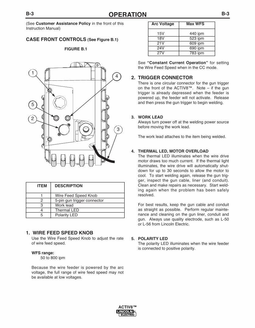
CASE FRONT CONTROLS (See Figure B.1)
ITEM DESCRIPTION
1 Wire�Feed�Speed�Knob2 5-pin�gun�trigger�connector3 Work�lead4 Thermal�LED5 Polarity�LED
1
3
5
2
4
FIGURE B.1
Arc Voltage Max WFS
15V 440�ipm18V 523�ipm21V 609�ipm24V 690�ipm27V 783�ipm
See�“Constant Current Operation” for� settingthe�Wire�Feed�Speed�when�in�the�CC�mode.
2. TRIGGER CONNECTORThere�is�one�circular�connector�for�the�gun�triggeron� the� front� of� the�ACTIV8™.� �Note�–� if� the�guntrigger� is� already�depressed�when� the� feeder� ispowered�up,�the�feeder�will�not�activate.��Releaseand�then�press�the�gun�trigger�to�begin�welding.
3. WORK LEADAlways�turn�power�off�at�the�welding�power�sourcebefore�moving�the�work�lead.
The�work�lead�attaches�to�the�item�being�welded.
4. THERMAL LED, MOTOR OVERLOADThe� thermal� LED� illuminates�when� the�wire� drivemotor�draws�too�much�current.��If�the�thermal�lightilluminates,� the�wire� drive�will� automatically� shut-down� for� up� to� 30� seconds� to� allow� the�motor� tocool.��To�start�welding�again,�release�the�gun�trig-ger,� inspect� the�gun� cable,� liner� (and� conduit).Clean�and�make�repairs�as�necessary.��Start�weld-ing�again�when� the�problem�has�been� safelyresolved.
For� best� results,� keep� the�gun� cable�and� conduitas� straight� as�possible.� �Perform� regular�mainte-nance�and�cleaning�on� the�gun� liner,�conduit�andgun.� �Always�use�quality�electrode,� such�as�L-50or�L-56�from�Lincoln�Electric.
5. POLARITY LEDThe�polarity�LED�illuminates�when�the�wire�feederis�connected�to�positive�polarity.

B-4OPERATIONB-4
ACTIV8™
INTERNAL CONTROLS (See Figure B.2)
ITEM DESCRIPTION
1 Pressure�Arm2 Cold�Feed�/�Gas�Purge�Switch3 2-Step�/�Trigger�Interlock�Switch4 CV�/�CC�Switch5 Spool�Retainer6 Spindle�Brake7 Gun� Bushing,� Thumb� Screw� and
Socket�Head�Cap�Screw.8 Drive�Hub�
1. PRESSURE ARM (See�“Installation Section” for�function.)
2. COLD FEED / GAS PURGE SWITCH
Place� the� rocker� (momentary)� switch� in� the�FOR-WARD�position� for� cold� feeding,� or� in� the�REARposition�for�gas�purge.
When� cold� feeding,� the�wire� drive�will� feed�elec-trode�but�neither�the�feedplate�nor�the�gas�solenoidwill�be�energized.��Adjust�the�speed�of�cold�feedingby� rotating� the�WFS�knob.�Cold� feeding,� or� "coldinching"� the�electrode� is� useful� for� threading� thee l e c t r o d ethrough� thegun.
FIGURE B.2
1
5
2 3
6
8
7
4
When�gas�purging� the�gas� solenoid� valve�willenergize�but�neither� the�power�source�output�northe�drive�motor�will�be�turned�on.��The�Gas�Purgeswitch� is�useful� for�setting� the�proper� flow� rate�ofshielding�gas.�
3. 2-STEP/ TRIGGER INTERLOCKSWITCH
The�2-Step/Trigger� Interlock� switch� changes� thefunction�of�the�gun�trigger.�2-Step�trigger�operationturns�welding�on�and�off� in� direct� response� to� thetrigger.�Trigger�Interlock�operation�allows�welding�tocontinue�when�the�trigger�is�released�for�comfort�onlong�welds.
Place� the�rocker�switch� in� the�DOWN�position� for2-Step�operation�or� in� the�UP�position� for�TriggerInterlock�operation.
2-Step Trigger
2-Step� trigger� operation� isthe�most� common.� �Whenthe�gun� trigger� is� pulled,the�welding�power� sourceenergizes� the�electrodeoutput�and�the�wire� feederfeeds�wire�for�welding.�Thepower� source� and� wirefeeder� continue�weldinguntil�the�trigger�is�released.��

B-5OPERATIONB-5
ACTIV8™
Trigger Interlock
Trigger� Interlock�operation�provides� for� operatorcomfort�when�making� long�welds.� �When� the�guntrigger� is� first� pulled,� the�welding�power� sourceenergizes� the�output� and� the�wire� feeder� feedswire� for�welding.�The�gun�trigger� is� then�releasedwhile� the�weld� is�made.�To�stop�welding,� the�guntrigger�is�pulled�again,�and�when�it�is�released�thewelding�power�source�output�turns�off�and�the�wirefeeder�stops�feeding�wire.
If the arc goes out while welding withtrigger interlock operation, the elec-trode output from the welding powersource remains energized and the wirefeeder will continue to feed wire untilthe gun trigger is again pulled andthen released.
------------------------------------------------------------------------
4. CV/CC SWITCH
The�CV/CC�switch�sets�the�wire�feed�speed�con-trol�method�for�the�wire�feeder.
Place�the�rocker�switch�in�the�UP�position�for�CCoperation�or�in�the�DOWN�position�for�CV�opera-tion.
In�the�CC�position,�thewire�feed�speed�variesduring�welding.��The�arclength�is�maintained�bychanging�the�wire�feedspeed.
In�the�CV�position,�thewire�feed�speed�remainsconstant�during�welding.A�steady�arc�voltage�isregulated�by�the�power�source�by�adjusting�the�arccurrent.
5. SPOOL RETAINER*
6. SPOOL BRAKE*
7. GUN BUSHING, THUMB SCREW ANDSOCKET HEAD CAP SCREW*
8. DRIVE ROLLS AND WIRE GUIDES** (See�“Installation Section” for�functions.)
CAUTION
REAR CONTROLS (See Figure B.3)
ITEM DESCRIPTION
1 Shielding�Gas�Inlet�with�gas�filter2 Electrode�Lead
FIGURE B.3
1
2

50
100
150
200
250
300
350
400
450
500
550
600
650
700
50 100 150 200 250 300 350 400 450 500 550 650 700
35
31
29
27
25
23
21
19
17
15
33
600
M15242-2VM
V
CC
A constant voltage (CV) power source is recommended for !ux-cored arc welding (FCAW) and gas metal arc welding (GMAW) to obtain c ode quality results. However, this wire feeder may also be used with a c onstant current (CC) power source to obtain passable results for noncritical q uality applications.
arco tubular (FCAW) y soldadura de arco metálico co n gas (GMAW) a #n de obtener resultados de calidad. Sin embargo, este a limentador de alambre también
resultados aceptables para aplicaciones que demanda n menor calidad.
On recommande une source de puissance à tension con stante (CV) pour le soudage à l'arc avec électrode fourrée (FCAW) et le soudage à l'arc gaz métal (GMAW) pour obtenir des résultats de grande qualité . Cependant, ce chargeur de #l peut aussi être utilisé avec une source de puis sance à courant constant (CC) pour obtenir des résultats acceptables pour des app lications de moindre qualité.
B-6OPERATIONB-6
ACTIV8™
FIGURE B.4
A�constant� voltage� (CV)�powersource� is� recommended� for� flux-cored�arc�welding.� (FCAW)�andgas�metal� arc�welding� (GMAW)� toobtain� code� quality� results.However,�this�wire�feeder�may�alsobe�used�with� a� constant� current(CC)�power�source�to�obtain�pass-able� results� for� noncritical� qualityapplications.
ARCVOLTS
The serviceability of a product or structure utiliz-ing the ACTIV8™ wire feeder is and must be thesole responsibility of the builder/user. Many vari-ables beyond the control of The Lincoln ElectricCompany affect the results obtained in using theACTIV8™ wire feeder. These variables include,but are not limited to, welding procedure, platechemistry and temperature, weldment design, fab-rication methods and service requirements. Theavailable range of the ACTIV8™ wirefeeder maynot be suitable for all applications, and thebuilder/user is and must be solely responsible forwelding settings.
CONSTANT CURRENT OPERATION
Setting Wire Feed Speed in CC mode
When�Across� the�Arc�models� are�operated�with�CCpower� sources,� the�wire� feed� speed� changes�as� thearc�voltage�changes.��When�the�arc�voltage�increases,the�wire� feed� speed�will� increase;� and�when� the�arcvoltage�decreases,�the�wire�feed�speed�will�decrease.
To�preset�the�wire�feed�speed�on�CC�power�sources:
1.�Set� the�Wire� Feed�Mode� switch� inside� theACTIV8™ to�"CC".
2.�Refer�to�the�Figure�B.4�graph�to�determine�cc�set-ting�of�the�wire�feed�speed�knob.��Select�the�hori-zontal� line� representing� the�Desired�Wire�FeedSpeed.�(See�Figure�B.4�arrow�for�375�in/min.)
3.�Select� the�diagonal� line� representing� the�ArcVolts.��(See�Figure�B.4�for�29�volts.)
4.�Determine� the� vertical� line� representing� the�CCWire�Feed�Speed� setting�where� the�above� twolines�cross.� (See�Figure�B.4�arrow� line� for�450.)Set� the�ACTIV8™ wire� feed� speed� knob� to� thisvalue.
CC�WFS�dial�setting�=�desired�WFS�x�35Arc�Volts
Example:375�in/min.�(Horizontal�Line)�x�3529�Arc�Volts�(Diagonal�Line)
=����452.5�(Vertical�Line)(See�Figure�B.4)�
=�
Use 450 setting

B-7OPERATIONB-7
ACTIV8™
If� the� contact� tip� to�work�distance� is� properly�main-tained,�a�satisfactory�operating�voltage�range�may�beachieved,� and�a� sound�weld�may� result.� �However,when�a�welder�uses�a� longer�contact� tip� to�work�dis-tance,� an�arc-sensing�wire� feeder� compensates�byincreasing�the�wire�feed�speed�to�regulate�the�voltage.Even�if�the�voltage�and�current�remain�unchanged,�theincreased�wire� feed�speed�may�result� in�a�depositionrate�well�beyond�the�specified�range�of�the�electrode.Under�these�conditions,�the�specified�weld�metal�prop-erties�may�not�be�achieved.
Constant�voltage�power�sources�deliver� large�currentsurges�to�stabilize�the�arc�when�the�electrode�is�short-ed�or�the�arc�length�is�very�short.�However,�a�constantcurrent� power� source�does�not� provide� such�aresponse� to� stabilize� the�arc.� It�may�be�difficult� toachieve��required�weld�metal�properties,�or�to�achievethe�required�quality�of�welds�needed�� to�pass�nonde-structive�tests,�when�such�welds�are�made�under�con-stant�current�operation.
For�these�reasons,�Lincoln�Electric�does�NOT recom-mend� constant� current� semiautomatic�welding� forapplications�which�need�to�meet�specified�weld�metalchemical�or�mechanical�property�requirements�or�weldquality�requirements.
Constant CurrentPower Source
Current
Current
Wire Feeder
WFSCTWD
Welding Cable(Electrode)
Welding Cable(Work)
GUN AND CABLE ASSEMBLY+
-
FIGURE B.5
CONSTANT CURRENT OPERATION(�See�Figure�B.5)
Lincoln Electric does NOT recommend constantcurrent semiautomatic welding for applicationswhich need to meet specified weld metal chemicalor mechanical property requirements or weldquality requirements.-----------------------------------------------------------------Most� semiautomatic�welding�processes�perform�betterusing�constant�voltage�power�sources.�
Welding�codes�usually�do�not�address�the�power�sourceselection�or� specifically,�whether� the�welding�process� isto�be�operated�in�the�constant�voltage�or�constant�currentmode.��Instead,�codes�typically�specify�limitations�on�thecurrent,� voltage,� heat� input� and�preheat� temperaturebased�on� the�material� to� be�welded.�The� intention� is� toassure�that�proper�weld�material�properties�will�develop.
Welding� is�sometimes�performed�using�constant�currentpower� sources.�The�operation� can�be�more� convenientbecause�it�may�allow�the�use�of�an�existing�stick�(SMAW)power�source�and�the�power�source�can�be�placed�at�adistant� location�without� any�provision� for� adjusting� theoutput�settings.�
For�constant�current�operation,�the�power�source�is�set�todeliver�the�specified�current.�The�power�source�regulatesthis�current�regardless�of�changes� in�the�welding�circuit,including� cable� length,� electrode�diameter,�wire� feedspeed,�contact�tip�to�work�distance,�etc.
Changes� in� the�wire� feed�speed�(WFS)�or�contact� tipto�work�distance�(CTWD)�affect�the�arc�voltage�whenconstant� current� power� sources�are�used.� Loweringthe�wire� feed� speed� raises� the� voltage,� raising� thewire�feed�speed�lowers�the�voltage.��Lengthening�thecontact� tip� to�work�distance�raises� the�voltage,�short-ening�the�contact�tip�to�work�distance�lowers�the�volt-age.
CAUTION
B-8OPERATIONB-8
ACTIV8™
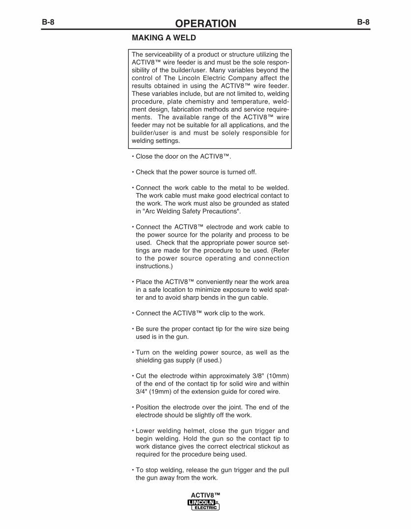
MAKING A WELD
The�serviceability�of�a�product�or�structure�utilizing�theACTIV8™�wire�feeder�is�and�must�be�the�sole�respon-sibility�of�the�builder/user.�Many�variables�beyond�thecontrol� of�The�Lincoln�Electric�Company�affect� theresults� obtained� in� using� the�ACTIV8™�wire� feeder.These�variables�include,�but�are�not�limited�to,�weldingprocedure,� plate� chemistry� and� temperature,�weld-ment�design,�fabrication�methods�and�service�require-ments.� � The�available� range�of� the�ACTIV8™�wirefeeder�may�not�be�suitable�for�all�applications,�and�thebuilder/user� is� and�must� be� solely� responsible� forwelding�settings.
•�Close�the�door�on�the�ACTIV8™.
•�Check�that�the�power�source�is�turned�off.
•�Connect� the�work� cable� to� the�metal� to� be�welded.The�work�cable�must�make�good�electrical�contact�tothe�work.�The�work�must�also�be�grounded�as�statedin�"Arc�Welding�Safety�Precautions".
•�Connect� the�ACTIV8™�electrode�and�work�cable� tothe�power�source� for� the�polarity�and�process� to�beused.��Check�that�the�appropriate�power�source�set-tings�are�made�for�the�procedure�to�be�used.�(Referto� the�power� source�operating�and� connectioninstructions.)
•�Place�the�ACTIV8™�conveniently�near�the�work�areain�a�safe�location�to�minimize�exposure�to�weld�spat-ter�and�to�avoid�sharp�bends�in�the�gun�cable.
•�Connect�the�ACTIV8™�work�clip�to�the�work.
•�Be�sure�the�proper�contact�tip�for�the�wire�size�beingused�is�in�the�gun.
•�Turn�on� the�welding�power� source,� as�well� as� theshielding�gas�supply�(if�used.)
•�Cut� the�electrode�within�approximately�3/8"� (10mm)of�the�end�of�the�contact�tip�for�solid�wire�and�within3/4"�(19mm)�of�the�extension�guide�for�cored�wire.
•�Position�the�electrode�over� the� joint.�The�end�of� theelectrode�should�be�slightly�off�the�work.
•�Lower�welding�helmet,� close� the�gun� trigger� andbegin�welding.�Hold� the�gun� so� the� contact� tip� towork�distance�gives�the�correct�electrical�stickout�asrequired�for�the�procedure�being�used.
•�To�stop�welding,�release�the�gun�trigger�and�the�pullthe�gun�away�from�the�work.
C-1ACCESSORIESC-1
ACTIV8™
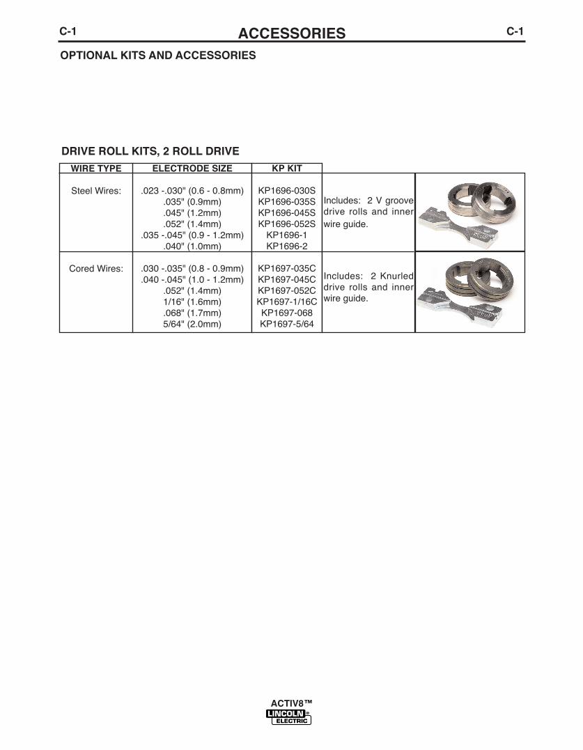
WIRE TYPE
Steel�Wires:
Cored�Wires:
ELECTRODE SIZE
.023�-.030"�(0.6�-�0.8mm).035"�(0.9mm).045"�(1.2mm).052"�(1.4mm)
.035�-.045"�(0.9�-�1.2mm)��.040"�(1.0mm)
.030�-.035"�(0.8�-�0.9mm)
.040�-.045"�(1.0�-�1.2mm).052"�(1.4mm)1/16"�(1.6mm).068"�(1.7mm)5/64"�(2.0mm)
KP KIT
KP1696-030SKP1696-035SKP1696-045SKP1696-052SKP1696-1KP1696-2
KP1697-035CKP1697-045CKP1697-052CKP1697-1/16CKP1697-068KP1697-5/64
Includes:��2�V�groovedrive� rolls� and� inner
wire�guide.�
Includes:� � 2�Knurleddrive� rolls� and� innerwire�guide.
DRIVE ROLL KITS, 2 ROLL DRIVE
OPTIONAL KITS AND ACCESSORIES

C-2ACCESSORIESC-2
ACTIV8™
K3061-1
K1803-1
K1840-xx
K1841-xx
K852-95
K2946-1
K1842-xx
KP3103-1
K3156-1
Plastic�Case
Work�and�Feeder�Cables�Package.
Weld�Power�Cable,�Twist-Mate�to�Lug.
Weld�Power�Cable,Twist-Mate�to�Twist-Mate.
Twist-Mate�Plug.
Tweco®�Style�Cam-Lock�Adapter
Plug�for�Work�&�Electrode�Cables.
Weld�Power�Cable,�Lug�to�Lug.
Shielding�Gas�Filter
Flow�Meter�Kit
Includes:�a�complete�engi-neered�plastic�case.
Includes:�Twist-Mate� to� Lug�2/0� cable14'� (1.2m)� long�with�Ground�Clamp,and�Twist-Mate� to� Lug�2/0�Cable�9'(2.7m)�long.
Includes:��Twist-Mate�to�Lug,
1/0�cable�of�length�"xx".
Includes:��Twist-Mate�to�Twist-mate,�1/0�Cable�of�length�“xx”for�length�25’(7.6m).��Twist-Mate�to�Twist-mate,�2/0�Cableof�length�“xx”�for�length50’(15.2).
Includes:��Twist-Mate�Plug,rubber�boot,�(2)�set�screws.
Includes:��Tweco®�Style�Cam-Lock�Adapter�Plug�for�2/0(70mm2)�cable,��rubber�boot,(2)�set�screws,�(1)�Fillisterhead�screw.
Includes:��Lug�to�Lug,�3/0Cable�of�length�"xx"�for�lengthsup�to�60'�(18.3m).��Lug�to�Lug,4/0�Cable�of�length�"xx"�forlengths�greater�than�60'(18.3m).
Includes�one�in-line�shieldinggas�filter.
Includes�one�in-line�flow�meterassembly.

C-3ACCESSORIESC-3
ACTIV8™
K910-1
K910-2
K1500-1
Ground�Clamp
Ground�Clamp
Gun�Receiver�Bushing�(for�gunswith�K466-1�Lincoln�gun�connec-tors;�Innershield�and�Subarc�guns)
Includes:��One�300�AmpGround�Clamp.
Includes:��One�500�AmpGround�Clamp.
Includes:��Gun�receiver�bush-ing,�set�screw�and�hex�key
wrench.
K484 Jumper�Plug�Kit
Includes:�����14�pin�circularconnector�with�jumper�forleads�2-4.��For�use�in�powersources�for�turning�the�weldterminals�"ON"�at�all�times.
K1500-2
K1500-3
K1500-4
K1546-2
K586-1
K283
Gun�Receiver�Bushing�(for�gunswith�K466-2,�K466-10�Lincoln�gunconnectors;�Magnum�200/300/400guns�and�compatible�with�Tweco®
#2-#4)
Gun�Receiver�Bushing�(for�gunswith�K613-7�Lincoln�gun�connec-tors;�Magnum�550�guns�and�com-
patible�with�Tweco®�#5)
Gun�Receiver�Bushing�(for�gunwith�K466-3�Lincoln�gun�connec-tors;�compatible�with�Miller®�guns.)
Incoming�Bushing�for�LincolnConduit
Deluxe�Adjustable�Gas�Regulator.
Wire�Feed�Speed�Meter
Includes:�Gun�receiver�bush-ing�with�hose�nipple,�set�screw
and�hex�key�wrench.
Includes:��Gun�receiver�bush-ing�with�hose�nipple,�set�screw
and�hex�key�wrench.
Includes:��Gun�receiver�bush-ing�with�hose�nipple,�set�screw
and�hex�key�wrench.
Includes:�Feed�Plate�IncomingBushings�connect�directly�to�wireconduit�(not�included),�for�use�inboom�system,�long�distances,�orlarge�payoff�packages.�Bushingscan�be�used�with�any�wire�conduit(K515�or�K565).�For�1/16-1/8�in
diameter�wire.NOTE: T10642-325�Flex�Tube
Required�with��K1546-2
Includes:��Deluxe�Gas�Regulator
for�Mixed�Gases,�Adapter�for�CO2
and�10'�(3.0m)�Hose.
Includes:�A�wire�feed�speedmeter�with�digital�display.��

D-1MAINTENANCED-1
ACTIV8™
ELECTRIC SHOCK can kill.• Do not operate with covers
removed.• Turn off power source before
installing or servicing.• Do not touch electrically hot
parts.
• Turn the input power to the welding powersource off at the fuse box before working in theterminal strip.
• Only qualified personnel should install, use orservice this equipment.
WARNING
SAFETY PRECAUTIONS
ROUTINE MAINTENANCERoutine�maintenance� consists� of� periodically� blowingout� the�machine,� using�a� low�pressure�airstream,� toremove�accumulated�dust� and�dirt� from� inside� thefeeder.�Check�weld� cables,� control� cables�and�gas
hoses�for�cuts.
PERIODIC MAINTENANCE•�Replace� the�drive� rolls� and� inner�wire� guide�when
they�are�worn.
•�Blow�out�or�vacuum�the�inside�of�the�feeder.

D-2MAINTENANCED-2
ACTIV8™
CALIBRATION SPECIFICATION
Calibration�of� the�ACTIV8™�may�be� required�whenthe�p.c.� board,�wire� feed� speed�potentiometer� ormotor� is� replaced�or� serviced.� �Calibration�matchesthe� scale�on� the�name�plate� to� the�actual�wire� feedspeed.
To calibrate the ACTIV8™:
1.�Turn�power�OFF�at�the�welding�power�source.
2.�Remove�the�spool�of�wire�from�the�feeder.��Removethe�gun� from� the� feed�plate.� �Remove� the�plasticcase� from� the�center�panel�assembly.� (See�FigureD.1)
3.�Connect� the�ACTIV8™�to� the�constant�voltage�DCpower�supply�capable�of�supply�at� least�9�amps�orwelding�power�source.�Connect�the�electrode�to�the“+”�positive�terminal�and�the�work�clip�to�the�“-”�neg-ative�terminal.�Set�the�CC/CV�switch�to�“CV”.
4.�Attach�the�gun�trigger�to�the�5�pin�amphenol�at�thefront�of�the�feeder.��
5.�Open�the�wire�drive�pressure�arm.
6.�Adjust� the�WFS�knob� to�50� IPM.� �Activate� the�guntrigger�connected�to�the�wire�feeder.
7.�Measure�WFS.��If�reading�is�49�to�51�IPM,�proceedto�step�8.��If�not�unplug�J3,�insert�shorting�plug�intoControl�PC�Board�J3�(shorts�pins�4�&�8),�and�adjustWFS�knob�to�49�to�51�IPM�and�remove�the�shortingplug.
8.�Set�WFS�knob�to�300�IPM.
9.�Measure�WFS.� � If� reading� is�297� to�303� IPM,�pro-ceed� to� step�10.� � If� not,� insert� shorting�plug� intoControl�PC�Board�J3,�and�adjust�WFS�knob�to�297to�303�IPM�and�then�remove�the�shorting�plug.
10.�Set�WFS�knob�to�800�IPM.
11.�Measure�WFS.��If�reading�is�795�to�805�IPM�cali-bration�is�complete.��If�not,�insert�shorting�plug�intoControl�PC�Board�J3,�and�adjust�WFS�knob�to�795to�805�IPM�and�then�remove�the�shorting�plug.
12.�Release�the�gun�trigger.
13.�Turn�power�OFF�at� the�power� supply� or�weldingpower�source,�and�reassemble.
FFRRIICCTTIIOONN WWASHASHEERR
KEKEYYEDED WWASHASHEERR
SPRSPRIINNGGWWASHEASHERR
WWIINGNG NNUUTT
WWASHEASHERR
LOCKLOCK WWASHASHEERRNNUUTT
CCEENNTTERER PPAANELNEL ASBLASBLYY
WWIIRERE DDRRIIVEVE PRESSPRESSUURERE ARARMMPLAPLASSTTIICC CASCASEE
FFEEEEDD PLAPLATTEE
SPSPIINDLENDLE BOLBOLTT
SPSPIINDLNDLEE
KEKEYYEDED WWASHASHEERR
FIGURE D.1

E-1TROUBLESHOOTINGE-1
ACTIV8™
If� for�any� reason�you�do�not�understand� the� test�procedures�or�are�unable� to�perform� the� tests/repairs�safely,�contact�yourLocal Lincoln Authorized Field Service Facility for�technical�troubleshooting�assistance�before�you�proceed.
CAUTION
This�Troubleshooting�Guide� is� provided� to� help� youlocate�and� repair� possible�machine�malfunctions.Simply�follow�the�three-step�procedure�listed�below.
Step 1. LOCATE PROBLEM (SYMPTOM).
Look�under� the� column� labeled� “PROBLEM� (SYMP-TOMS)”.� � This� column�describes�possible� symptomsthat� the�machine�may�exhibit.� � Find� the� listing� thatbest� describes� the� symptom� that� the�machine� isexhibiting.�
Step 2. POSSIBLE CAUSE.
The�second�column�labeled�“POSSIBLE�CAUSE”�liststhe�obvious�external� possibilities� that�may� contributeto�the�machine�symptom.��
Step 3. RECOMMENDED COURSE OF ACTION
This� column�provides�a� course�of� action� for� thePossible�Cause,� generally� it� states� to� contact� yourlocal�Lincoln�Authorized�Field�Service�Facility.
If�you�do�not�understand�or�are�unable�to�perform�theRecommended�Course�of�Action�safely,� contact� yourlocal�Lincoln�Authorized�Field�Service�Facility.
HOW TO USE TROUBLESHOOTING GUIDE
Service�and�Repair� should�only� be�performed�by�Lincoln�Electric�Factory�Trained�Personnel.Unauthorized� repairs� performed�on� this� equipment�may� result� in� danger� to� the� technician�andmachine�operator�and�will� invalidate�your� factory�warranty.� �For� your� safety�and� to�avoid�ElectricalShock,�please�observe�all�safety�notes�and�precautions�detailed�throughout�this�manual.
__________________________________________________________________________
WARNING
E-2TROUBLESHOOTINGE-2
ACTIV8™
Observe all Safety Guidelines detailed throughout this manual
If� for�any� reason�you�do�not�understand� the� test�procedures�or�are�unable� to�perform� the� tests/repairs�safely,�contact�yourLocal Lincoln Authorized Field Service Facility for�technical�troubleshooting�assistance�before�you�proceed.
CAUTION
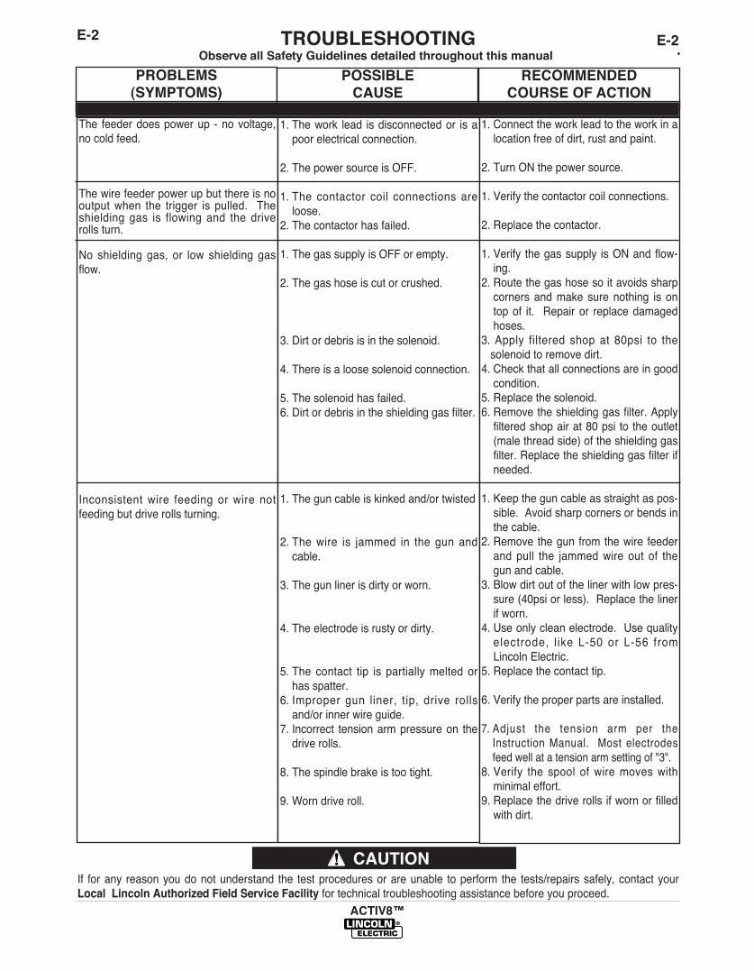
PROBLEMS(SYMPTOMS)
POSSIBLECAUSE
RECOMMENDEDCOURSE OF ACTION
The� feeder�does�power�up� -�no�voltage,no�cold�feed.
The�wire�feeder�power�up�but�there�is�nooutput�when� the� trigger� is� pulled.� � Theshielding�gas� is� flowing�and� the�driverolls�turn.
No� shielding�gas,� or� low� shielding�gasflow.
Inconsistent�wire� feeding�or�wire� notfeeding�but�drive�rolls�turning.
1.�The�work� lead� is�disconnected�or� is�apoor�electrical�connection.�
2.�The�power�source�is�OFF.
1.�The� contactor� coil� connections�areloose.
2.�The�contactor�has�failed.
1.�The�gas�supply�is�OFF�or�empty.
2.�The�gas�hose�is�cut�or�crushed.
3.�Dirt�or�debris�is�in�the�solenoid.
4.�There�is�a�loose�solenoid�connection.
5.�The�solenoid�has�failed.6.�Dirt�or�debris�in�the�shielding�gas�filter.
1.�The�gun�cable�is�kinked�and/or�twisted
2.�The�wire� is� jammed� in� the�gun�andcable.
3.�The�gun�liner�is�dirty�or�worn.
4.�The�electrode�is�rusty�or�dirty.
5.�The� contact� tip� is� partially�melted�orhas�spatter.
6.�Improper� gun� liner,� tip,� drive� rollsand/or�inner�wire�guide.
7.�Incorrect� tension�arm�pressure�on� thedrive�rolls.
8.�The�spindle�brake�is�too�tight.
9.�Worn�drive�roll.
1.�Connect�the�work�lead�to�the�work�in�alocation�free�of�dirt,�rust�and�paint.
2.�Turn�ON�the�power�source.
1.�Verify�the�contactor�coil�connections.
2.�Replace�the�contactor.
1.�Verify� the�gas�supply� is�ON�and�flow-ing.
2.�Route�the�gas�hose�so�it�avoids�sharpcorners�and�make� sure�nothing� is� ontop�of� it.� �Repair�or� replace�damagedhoses.
3. Apply� filtered� shop�at� 80psi� to� thesolenoid�to�remove�dirt.
4.�Check�that�all�connections�are�in�goodcondition.
5.�Replace�the�solenoid.6.�Remove�the�shielding�gas�filter.�Applyfiltered�shop�air�at�80�psi� to�the�outlet(male�thread�side)�of�the�shielding�gasfilter.�Replace�the�shielding�gas�filter�ifneeded.
1.�Keep�the�gun�cable�as�straight�as�pos-sible.��Avoid�sharp�corners�or�bends�inthe�cable.
2.�Remove�the�gun�from�the�wire� feederand�pull� the� jammed�wire�out� of� thegun�and�cable.
3.�Blow�dirt�out�of�the�liner�with�low�pres-sure�(40psi�or�less).��Replace�the�linerif�worn.
4.�Use�only�clean�electrode.��Use�qualityelectrode,� l ike�L-50�or� L-56� fromLincoln�Electric.
5.�Replace�the�contact�tip.
6.�Verify�the�proper�parts�are�installed.
7.�Adjust� the� tension� arm� per� theInstruction�Manual.� �Most� electrodesfeed�well�at�a�tension�arm�setting�of�"3".
8.�Verify� the� spool� of�wire�moves�withminimal�effort.��
9.�Replace�the�drive�rolls�if�worn�or�filledwith�dirt.

E-3TROUBLESHOOTINGE-3
ACTIV8™
Observe�all�Safety�Guidelines�detailed�throughout�this�manual
If� for�any� reason�you�do�not�understand� the� test�procedures�or�are�unable� to�perform� the� tests/repairs�safely,�contact�yourLocal Lincoln Authorized Field Service Facility for�technical�troubleshooting�assistance�before�you�proceed.
CAUTION
PROBLEMS(SYMPTOMS)
POSSIBLECAUSE
RECOMMENDEDCOURSE OF ACTION
Wire� feed� speed� consistently� oper-ates�at�the�wrong�value.��The�speedchanges�when� the�wire� feed� speedknob�is�adjusted.
The�wire� feed� speed� stuck�at� 200-300� in/min�and� there� is� no� changewhen� the�wire� feed� speed� knob� isadjusted.
Variable�or�"hunting"�arc.
Poor� arc� starts� with� sticking� or"blast-offs",�weld�porosity,� narrowand�ropy�looking�bead.
1.�The�brushes�on� the�motor� areworn.
1.�The� tachometer� is� connectedimproperly.
2.�The�tachometer�has�failed.
1.�Wrong� size,�worn�and/or�meltedcontact�tip.
2.�Worn�work� cable�or� poor�workconnection.
3.�Wrong�polarity.
4.�The� gas� nozzle� is� extendedbeyond�the�contact� tip�or� the�wirestickout�is�too�long.
5.�Poor� gas� shielding�on�processesrequiring�gas.
Improper�procedures�or�techniques.
1.�Replace� the�motor� and� tachome-
ter�assembly.
1.�Verify� all� of� the� tachometer� leadsare�properly�connected.
2.�Replace� the�motor� and� tachome-ter�assembly.
1.�Replace�the�contact�tip.
2.�Verify�all�work�and�electrode�con-nections�are� tight� and� that� thecables� are� in� good� condit ion.Clean/replace�as�necessary.
3.�Adjust�polarity�to�the�recommend-ed�procedure.� �Verify�DIP� switch#7� setting�matches� the�electrodepolarity.
4.�Adjust�the�gas�nozzle�and�shortenthe�stickout�to�½�to�¾�inches.
5.�Check� gas� flow� and� mixture.Remove� or� block� sources� ofdrafts.
See�"Gas�Metal�Arc�Welding�Guide"(GS-100)

F-1DIAGRAMSF-1
ACTIV8™
NOTE:��This�diagram�is�for�reference�only.���It�may�not�be�accurate�for�all�machines�covered�by�this�manual.��The�specific�diagram�for�a�particular�code�is�pasted�inside�the
machine�on�one�of�the�enclosure�panels.��If�the�diagram�is�illegible,�write�to�the�Service�Department�for�a�replacement.��Give�the�equipment�code�number.

F-2DIMENSION PRINTF-2
ACTIV8™
L16081A.
02
19.5
7
19.8
0
7.60
13" C
IRCL
E
11" X
14"
ELL
IPSE
11.7
3

NOTES
ACTIV8™

ACTIV8™
P-677P-677
PARTS LIST FOR
ACTIV8™

ACTIV8™ 09-15-2011
P-677-AP-677-A
ILLUSTRATION OF SUB-ASSEMBLIES
11
22
33

ACTIV8™ Mar-2014
Do Not use this Parts List for a machine if its code number is not listed. Contact the Service Department for anycode numbers not listed.
Use the Illustration of Sub-Assemblies page and the table below to determine which sub assembly page andcolumn the desired part is located on for your particular code machine.
P-677-A.1P-677-A.1
ACTIV8™
For Code: 11770, 12198
CODE NO.
11770 1 1 1 1
12198 1 1 1 2
P.C
. B
oard
s,
Fan &
Conta
cto
rA
ssem
bly
P-677-E
3
Wire D
rive A
ssem
bly
, S
pin
dle
&M
iscella
neous
P-677-D
2
Pla
stic C
ase A
ssem
bly
P-677-C
1
Mis
cella
neous I
tem
s
P-677-B.1
SUB ASSEMBLY PAGE NAME
PAGE NO.
Sub Assembly ItemNo.

MISCELLANEOUS ITEMS (THESE ITEMS ARE NOT ILLUSTRATED)
Inert Arc Nut (Brass) T15007-1 1 XHose Nipple (Brass) T15008 1 XFlex Tube T10642-325 1 XGround Lead Assembly S17211-7 1 X
05-31-2012
Use only the parts marked “x” in the column under theheading number called for in the model index page.
# Indicates a change this printing.
P-677-B.1
DESCRIPTION PART NO. QTY. 1 2 3 4 5 6 7 8 9
P-677-B.1
ACTIV8™

ACTIV8™
NOTES

ACTIV8™ 09-15-2011
P-677-CP-677-C
Plastic Case Assembly
1A1A
33
22
1B1B
55
13A13A13B13B 13C13C
77
1D1D
1E1E
1C1C

Complete Plastic Case Asbly (G7039), Includes: K3061-1 1 XPlastic Case Asbly (G6696), Includes: NSS 1 X
1A Case NSS 1 X1B Door NSS 1 X1C Hinge Pin S26671-2 1 X1D Hinge Pin S26671-3 1 X1E Door Latch M20977-1 1 X1F Metric Screw (Not Shown) T14731-73 2 X2 Speed Nut T11525-8 2 X3 Warning Decal S20601-4 1 X4 Procedure Decal (Not Shown) L16003 1 X5 Decal (Rating) (L16002-2) (Part of L16002) NSS 1 X6 Decal (LECO Logo) (Not Shown) (L16002-8) (Part of L16002) NSS 1 X7 Decal (Lincoln Logo) (L16002-9) (Part of L16002) NSS 1 X8 Decal (Product Name) (Not Shown) (L16002-10) (Part of L16002) NSS 1 X9 Decal (Product Name) (Not Shown) (L16002-11) (Part of L16002) NSS 1 X10 Warning Decal (Not Shown) S25815 1 X13A Self Drilling Screw S28933-1 3 X13B Lock Washer E106A-1 3 X13C Plain Washer S9262-27 3 X
10-17-2011ACTIV8™
Use only the parts marked “x” in the column under theheading number called for in the model index page.
# Indicates a change this printing.
P-677-C.1
ITEM DESCRIPTION PART NO. QTY. 1 2 3 4 5 6 7 8 9
P-677-C.1
NSS - Not Sold Separately

ACTIV8™ 10-17-2011
P-677-DP-677-D
Wire Drive Assembly, Spindle & Miscellaneous
11
2A2A
3636
3232
3535
2727
2B2B
5A5A
3737
39393838
4040
33
30A30A 30B30B
31A31A 31B31B
2323
2424
2222
2121
2020
1919
1818
4B4B
4E4E
7A7A
99
1010
1313 1414
1111
8A8A
8B8B
4G4G
4F4F
6A6A 6B6B6C6C
6D6D
4C4C
4D4D
4A4A
12A12A
12B12B
12C12C
25A25A 25B25B
25C25C2020

Wire Drive Assembly, Includes: G7040 1 X
1 Center Panel (Plastic) G6695 1 X
2A Connector & Harness Assembly, Includes: M22646-2 1 X
2B Connector (5 Socket) S12021-66 1 X
2C Self Tapping Screw (Not Shown) S8025-118 2 X
3 LED Lens (Includes S23094-1 Retaining Ring) S23093-1 2 X
4 Feedplate Assembly, Includes: M19932-7 1 X
4A Connection Bar M19611-1 1 X
4B Socket Head Cap Screw T9447-112 1 X
4C Plain Washer S9262-167 1 X
4D Retaining Ring S9776-69 1 X
4E Adjustment Arm Assembly M20593-3 1 X
4F Wire Guide Retaining Pin S22672 2 X
4G Shaft S25402 2 X
4H Set Screw (Not Shown) S11604-47 1 X
4K Thread Forming Screw (Not Shown) S9225-102 4 X
5A Motor Gearbox (with Tachometer) L15910 1 X
5B Lock Washer (Not Shown) E106A-2 3 X
5C M6 x1.00 PPNHS (Not Shown) T14731-18 3 X
6A Drive Gear M19870 1 X
6B Collar S25414 1 X
6C Lock Washer T4291-A 1 X
6D Metric Screw T14731-47 1 X
7A Ball Bushing Assembly M18947-1 1 X
7B Set Screw (Not Shown) S11604-21 1 X
8A Cover M19999 1 X
8B Thread Forming Screw S9225-102 1 X
9 Drive Roll Shaft Assembly S25638 2 X
10 Retainer S25403 2 X
11 Wire Guide Assembly KP2071-3 1 X
12A 1/2-13 x 1.00 HHCS CF000021 1 X
12B Lock Washer E106A-15 1 X
12C Plain Washer S9262-1 1 X
13 Gun Adapter Assembly S22905-2 1 X
14 Screw Stud T13858 1 X
18 Spindle L15659 1 X
19 Spindle Bolt Rework S28271 1 X
20 Friction Washer S17435-5 2 X
21 Keyed Washer T12965-3 2 X
22 Compression Spring T11862-68 1 X
23 Plain Washer S9262-120 1 X
24 Wing Nut T9968-5 1 X
25A Plain Washer S9262-120 1 X
25B Lock Washer E106A-16 1 X
25C 3/8-16 HJN CF000121 1 X
26 Speed Nut (Not Shown) T11525-8 1 X
27 #10-24 x 1.00 Self Drilling Screw S28933-1 3 X
30A Rocker Switch T10800-68 2 X
30B Rocker Switch Boot S28672-1 2 X
31A Rocker Switch T10800-69 1 X
31B Rocker Switch Boot S28672-2 1 X
Jan-14ACTIV8™
Use only the parts marked “x” in the column under theheading number called for in the model index page.
# Indicates a change this printing.
P-677-D.1
ITEM DESCRIPTION PART NO. QTY. 1 2 3 4 5 6 7 8
P-677-D.1

32 Potentiometer Knob M22778-2 1 X35 Decal, Nameplate (L16002-1) (Part of L16002) NSS 1 X36 Decal, Pressure Arm (L16002-3) (Part of L16002) NSS 1 X37 Decal, Cold Feed/Gas Purge (L16002-5) (Part of L16002) NSS 1 X38 Decal, 2 Step/Trigger Interlock (L16002-6) (Part of L16002) NSS 1 X39 Decal, CV/CC (L16002-7) (Part of L16002) NSS 1 X40 Decal, Panel (L16002-4) (Part of L16002) NSS 1 X
Oct-13ACTIV8™
Use only the parts marked “x” in the column under theheading number called for in the model index page.
# Indicates a change this printing.
P-677-D.2
ITEM DESCRIPTION PART NO. QTY. 1 2 3 4 5 6 7 8 9
P-677-D.2
NSS - Not Sold Separately

ACTIV8™
NOTES

ACTIV8™ 10-17-2011
P-677-EP-677-E
P.C. Boards, Fan & Contactor Assembly
10A10A
17A17A
18A18A
18B18B
19B19B
17B17B
9A9A
6A6A
7A7A
7D7D
88
5A5A
14A14A
2121
2020
14B14B
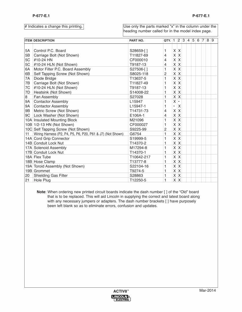
5A Control P.C. Board S28659-[ ] 1 X X5B Carriage Bolt (Not Shown) T11827-69 4 X X5C #10-24 HN CF000010 4 X X5C #10-24 HLN (Not Shown) T9187-13 4 X X6A Motor Filter P.C. Board Assembly S27506-[ ] 1 X X6B Self Tapping Screw (Not Shown) S8025-118 2 X X7A Diode Bridge T13637-5 1 X X7B Carriage Bolt (Not Shown) T11827-49 1 X X7C #10-24 HLN (Not Shown) T9187-13 1 X X7D Heatsink (Not Shown) S14008-22 1 X X8 Fan Assembly S27028 1 X X9A Contactor Assembly L15947 1 X •9A Contactor Assembly L15947-1 1 • X9B Metric Screw (Not Shown) T14731-73 4 X X9C Lock Washer (Not Shown) E106A-1 4 X X10A Insulated Mounting Block M21096 1 X X10B 1/2-13 HN (Not Shown) CF000027 1 X X10C Self Tapping Screw (Not Shown) S9225-99 2 X X11 Wiring Harness (P2, P4, P5, P6, P20, P61 & J7) (Not Shown) G6754 1 X X14A Cord Grip Connector S19999-5 1 X X14B Conduit Lock Nut T14370-2 1 X X17A Solenoid Assembly M17294-8 1 X X17B Conduit Lock Nut T14370-1 1 X X18A Flex Tube T10642-217 1 X X18B Hose Clamp T13777-8 1 X X19A Toroid Assembly (Not Shown) S22104-16 1 X X19B Grommet T9274-5 1 X X20 Shielding Gas Filter S28863 1 X X21 Hole Plug T12250-5 1 X X
Mar-2014ACTIV8™
Use only the parts marked “x” in the column under theheading number called for in the model index page.
# Indicates a change this printing.
P-677-E.1
ITEM DESCRIPTION PART NO. QTY. 1 2 3 4 5 6 7 8 9
P-677-E.1
Note: When ordering new printed circuit boards indicate the dash number [ ] of the “Old” boardthat is to be replaced. This will aid Lincoln in supplying the correct and latest board alongwith any necessary jumpers or adapters. The dash number brackets [ ] have purposelybeen left blank so as to eliminate errors, confusion and updates.

ACTIV8™
NOTES

NOTES
ACTIV8™

Customer assistanCe PoliCy
The business of The Lincoln Electric Company is manufacturing andselling high quality welding equipment, consumables, and cuttingequipment. Our challenge is to meet the needs of our customers andto exceed their expectations. On occasion, purchasers may askLincoln Electric for advice or information about their use of ourproducts. We respond to our customers based on the best informationin our possession at that time. Lincoln Electric is not in a position towarrant or guarantee such advice, and assumes no liability, withrespect to such information or advice. We expressly disclaim anywarranty of any kind, including any warranty of fitness for anycustomer’s particular purpose, with respect to such information oradvice. As a matter of practical consideration, we also cannot assumeany responsibility for updating or correcting any such information oradvice once it has been given, nor does the provision of informationor advice create, expand or alter any warranty with respect to the saleof our products.
Lincoln Electric is a responsive manufacturer, but the selection anduse of specific products sold by Lincoln Electric is solely within thecontrol of, and remains the sole responsibility of the customer. Manyvariables beyond the control of Lincoln Electric affect the resultsobtained in applying these types of fabrication methods and servicerequirements.
Subject to Change – This information is accurate to the best of ourknowledge at the time of printing. Please refer to www.lincolnelectric.com for any updated information.