operator's manual - allpower · operator's manual eb221s Éß˛Ò ... troubleshooting...
TRANSCRIPT

1T op cover
ÛÒÙÔ×ÍØ øÑ®·¹ ·² ¿ ́·² ¬®« ½ ¬·± ² ÷
OPERATOR'S MANUAL
EB221S
ÉßÎÒ×ÒÙÎÛßÜ ÌØÛ ×ÒÍÌÎËÝÌ×ÑÒÍ ÝßÎÛÚËÔÔÇ ßÒÜ ÚÑÔÔÑÉ ÌØÛ ÎËÔÛÍ ÚÑÎ ÍßÚÛ ÑÐÛÎßÌ×ÑÒòÚß×ÔËÎÛ ÌÑ ÜÑ ÍÑ ÝÑËÔÜ ÎÛÍËÔÌ ×Ò ÍÛÎ×ÑËÍ ×ÒÖËÎÇò

2
Important information2Important information
Please ensure that you read the operator's manual before using your product.
Intended use of this productThe shindaiwa Blowers are designed for blowing away dust of various sorts, including fallen leaves.Do not use this unit for any purpose other than aforementioned.
Users of the productYou should not use this product until you have read the operator's manual carefully and fully absorbed its content.This product should not be used by anyone who has failed to read the operator's manual properly, is suffering from a cold, tiredness or otherwise in poor physical condition, or children.Keep in mind that the operator or user is responsible for accidents or hazards occurring to other people or their prop-erty.
About your operator's manualThis manual contains necessary information about the assembly, operation, and maintenance of your product. Please read it carefully and absorb its contents.Always keep your manual in a place where it is readily accessible.If you have lost your manual or it is damaged and no longer readable, please purchase a new one from your shindaiwa dealer.The units used in this manual are SI units (International System of Units). Figures in parentheses are reference values, and there may be a slight conversion error in some cases.
Loaning or assigning your productWhen loaning the product described in this manual to another party, ensure that the person borrowing and working with the product receives the operator's manual along with the product. If you assign your product to another party, please enclose the operator's manual with the product when handing it over.
EnquiriesPlease contact your shindaiwa dealer for requests regarding information about your product, the purchase of consum-ables, repairs, and other such enquiries.
NoticesThe content of this manual may be changed without notice for the purpose of upgrades to the product. Some of the illustrations used may differ from the product itself in order to make the explanations clearer.This product requires the assembly of some parts.Please consult your shindaiwa dealer if anything is unclear or of concern.
Feature of this model: Soft StartSoft Start generates enough revolving power to rotate crankshaft up to a speed to ignite the engine and bring almost no kickback.Soft Start makes engine start far easier than you ever expect.
Manufacturer
YAMABIKO CORPORATION7-2 SUEHIROCHO 1-CHOME, OHME, TOKYO 198-8760, JAPAN
Authorized Representative in Europe
Atlantic Bridge LimitedAtlantic House, PO Box 4800, Earley, Reading RG5 4GB, United Kingdom

3
ContentsFor safe use of your product............................................................................................... 4
Warning notices............................................................................................................. 4Other indicators ............................................................................................................. 4Symbols ......................................................................................................................... 4Location in which the safety decal is attached............................................................... 6Handling fuel..................................................................................................................7Handling the engine....................................................................................................... 8Handling the product ..................................................................................................... 9
Packing list........................................................................................................................ 12Description........................................................................................................................ 13Before you start ................................................................................................................ 14
Assembly ..................................................................................................................... 14Preparing the fuel ........................................................................................................ 15
Engine operation............................................................................................................... 16Starting the engine ...................................................................................................... 16Stopping the engine..................................................................................................... 17
Operation .......................................................................................................................... 18Operating blower ......................................................................................................... 18
Maintenance and care ...................................................................................................... 19Servicing guidelines..................................................................................................... 19Maintenance and care ................................................................................................. 19Troubleshooting table .................................................................................................. 23Long-term storage(30 days or more) ........................................................................... 26
Specifications.................................................................................................................... 27Declaration of conformity .................................................................................................. 28

4
For safe use of your productFor safe use of your produc t
Be careful to read this section before using your product.The precautions described in this section contain important safety information. Please observe them carefully.You must also read the precautions that appear in the body of the manual itself.
Text following a [diamond mark] mark describes the potential consequences of failing to observe the precaution.
Warning noticesSituations where there is a risk of physical injury to the operator and other people are indicated in this manual and on the productitself by the following warning notices. Always read and observe them carefully in order to ensure safe operation.
Other indicatorsAs well as warning notices, this manual uses the following explanatory symbols:
SymbolsIn this manual and on the product itself, a series of explanatory symbols is used. Please make sure that you fully understand whateach symbol means.
DANGER WARNING CAUTIONThis symbol accompanied by the word "DANGER" calls attentions to an act or a condition which will lead to serious personal injury or death of op-erators and bystanders.
This symbol accompanied by the word "WARNING" calls attentions to an act or a condition which can lead to serious personal injury or death of op-erators and bystanders.
"CAUTION" indicates a potentially hazardous situation which, if not avoided, may result in minor or mod-erate injury.
Circle and slash sym-bol means whatever is shown is prohibited.
NOTE IMPORTANTThis enclosed message provides tips for use, care and maintenance of the product.
Framed text featuring the word "IM-PORTANT" contains important infor-mation about the use, checking, maintenance and storage of the prod-uct described in this manual.
Symbol form/shape Symbol description/applica-tion
Symbol form/shape Symbol description/applica-tion
Carefully read the operator's manual Petrol and oil mixture
Wear eyes, ears and head protection Purge bulb (Primer)
Safety / Alert Carburettor adjustment- Low speed mixture
Emergency stop Carburettor adjustment- High speed mixture
Finger Severing Carburettor adjustment- Idle speed

5
For safe use of your product
Do not use the product in plac-es with poor ventilation
Choke Control"Cold Start"Position(Choke Closed)
Beware of fire
Choke Control"Run"Position(Choke Open)
Beware of electric shocks Idle speed
Guaranteed sound power lev-el Fast speed
IgnitionON / OFF
Beware of high-temperature areas
Engine start Keep bystanders away 15 m
Symbol form/shape Symbol description/applica-tion
Symbol form/shape Symbol description/applica-tion
6
For safe use of your product
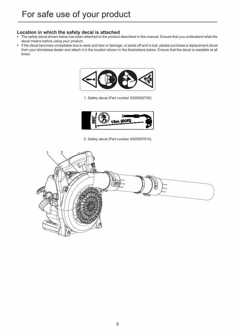
Location in which the safety decal is attachedThe safety decal shown below has been attached to the product described in this manual. Ensure that you understand what the decal means before using your product.If the decal becomes unreadable due to wear and tear or damage, or peels off and is lost, please purchase a replacement decal from your shindaiwa dealer and attach it in the location shown in the illustrations below. Ensure that the decal is readable at all times.
1. Safety decal (Part number X505002730)
2. Safety decal (Part number X505007910)

7
For safe use of your product
Handling fuel
DANGERAlways keep well away from fire when refuellingFuel is highly inflammable and leads to a risk of fire if mishandled. Use extreme care when mixing, storing or handlingor serious personal injury may result. Be careful to observe the following instructions.
Do not smoke or hold a flame near when refuelling.Do not fuel up while the engine is hot or in operation.If you do so, the fuel could ignite and cause fire, leading to burns.
About the container and refuelling placeUse an approved fuel container.Fuel tanks/cans may be under pressure.Always loosen fuel caps slowly allowing pressure to equalize.DO NOT fill fuel tanks indoors.ALWAYS fill fuel tanks outdoors over bare ground.
Fuel spills can cause fireObserve the following precautions when refuelling:
Do not add so much fuel that it reaches the mouth of the fuel tank. Keep the fuel within the prescribed level (up to the shoulder level of the fuel tank).Mop up any fuel that overflows or spills out due to over-filling.Tighten the fuel tank cap securely after refuelling.Fuel spills can cause fire and burns when ignited.
1. Fuel tank2. Shoulder level
Do not start the engine in the area where you refu-elled
You must not start the engine in the place where you carried out the refuelling. Move at least 3m from the place where you refuelled before starting the engine.Fuel leaks that occur while refuel-ling can cause fire if ignited.
Fuel leaks cause fireAfter refuelling, always check that there are no leaks or dis-charges of fuel from the fuel pipe, fuel system grommets, or around the fuel tank cap.If you do find fuel leaks or discharges, stop using the product immediately and contact your shindaiwa dealer to have it repaired.Any fuel leaks could cause fire.

8
For safe use of your productHandling the engine
WARNINGStarting the engineBe particularly careful to observe the following precau-tions when starting the engine:
Check that none of the nuts and bolts are looseCheck that there are no fuel leaksPlace the product in a flat, well ventilated placeLeave plenty of space around the product and do not al-low people or animals near itRemove obstructions, if anyStart the engine with the throttle lever in the start/oper-ation positionHold the product firmly to the ground when starting the engineFailure to observe the precautions could cause an accident or injury, or even lead to a fatality.
Once the engine has started, check for abnormal vi-brations and sounds
Check that there are no abnormal vibrations or sounds once the engine starts. Do not use the product if there are abnormal vibrations or sounds. Contact your shin-daiwa dealer to have it repaired.Accidents involving parts that fall or shatter off can cause wounds or serious injury.
Do not touch high temperature or high voltage com-ponents while the product is runningDo not touch the following high temperature or high volt-age components while the product is running or for sometime after it stops.
Silencer, cylinder, and other high tempera-ture componentsYou could burn yourself if you touch a high temperature component.
Spark plug, spark plug wire, and other high voltage componentsYou could receive an electric shock if you touch a high voltage component while the product is running.
Put safety first in the case of fire or smokeIf fire comes from the engine or smoke appears from any area other than the exhaust vent, first distance yourself from the product to ensure your physical safe-ty.Use a shovel to throw sand or other such material on the fire to prevent it from spreading, or put it out with a fire extin-guisher.A panicked reaction could result in the fire and other damage becoming more extensive.
Exhaust fumes are toxicThe exhaust fumes from the engine contain toxic gases. Do not operate the product indoors or in a plastic green-house or in other ill ventilated places.In case of conducting the work near the house, do not conduct the work near the opened window. There is the possibility that the exhaust fumes comes into the house.The exhaust fumes could cause poisoning.
Turn off the engine when checking or maintainingthe productObserve the following precautions when checking andmaintaining your product after use:
Turn the engine off and do not attempt to check or main-tain the product until the engine has cooledYou could burn yourself.Remove the spark plug cap before performing checks and maintenanceAn accident could occur if the product starts unexpectedly.
Checking the spark plugObserve the following precautions when checking thespark plug.
If the electrodes or terminals are worn, or if there are cracks in the ceramics, replace them with new parts.The spark test (for checking whether the spark plug is sparking) must be carried out by a professional. Please ask your shindaiwa dealer.The spark test must not be carried out in proximity of the spark plug hole.The spark test must not be performed in places where there are fuel spills or inflammable gases.You must not touch the metal parts of the spark plug.The spark plug could ig-nite a fire or give you an electric shock.

9
For safe use of your productHandling the productGeneral precautions
WARNINGOperator's manual
Be careful to read the operator's manual properly before using your product in or-der to ensure correct operation.Failure to do so could lead to an accident or serious injury.
Do not use the product for anythingother than its intended purpose
You must not use the product for any purpose other than those described in the operator's manual.To do so could lead to an accident or serious injury.
Do not modify the productYou must not modify the product.To do so could lead to an accident or serious injury. Any malfunction resulting from a modification to the product will not be covered by the manufacturer's warranty.
Do not use the product unless it has been checkedand maintained
You must not use the product unless it has been checked and maintained. Always ensure that the prod-uct is checked and maintained on a regular basis.Failure to do so could lead to an accident or serious injury.
Loaning or assigning your productWhen loaning your product to another party, ensure that the person borrowing the product receives the op-erator's manual along with it.If you assign your product to another party, please en-close the operator's manual with the product when handing it over.Failure to do so could lead to an accident or serious injury.
Being prepared in case of an injuryIn the unlikely event of an accident or injury, please ensurethat you are prepared.
First aid kitTowels and wipes (to stop any bleeding)Whistle or mobile phone (for calling outside help)If you are unable to perform first aid or call for outside help, the injury could worsen.

10
For safe use of your productPrecautions for use
WARNINGUsers of the productThe product should not be used by:
people who are tiredpeople who have taken alcoholpeople who are on medicationpeople who are pregnantpeople who are in poor physical conditionpeople who have not read the op-erator's manualchildrenFailure to observe these instruc-tions could lead to an accident.The ignition system of this product generates electromag-netic fields during operation. Magnetic fields can cause pacemaker interference or pacemaker failure. To reduce health risks, we recommend that pacemaker users consult their physician and the pacemaker manufacturer before op-erating this product.
Environment of use and operationDo not use the product in places where there is no sure foothold, such as on steep slopes or after rainfall, as such places are slippery and dangerous.Do not operate the product at night or in dark places with poor visibility.A serious injury could result if you fall or slip, or fail to oper-ate the product correctly.
The area within a 15 m radius is a danger zoneThe area within a 15 m radius of the product is a danger zone. Be careful to observe the following precautions while working with the product.
Do not allow children and other people or pets to enter the danger zone.If another person enters the danger zone, turn off the engine.When approaching the operator, signal to him by, for example, throwing twigs from outside the danger zone, and then check that engine has been switched off.If more than one person is working with the product, identify the way in which you will signal to each other and work at least 15 m apart.Thrown objects could cause serious injury to the operator or bystanders.
Using the productWhen using the product, pay special attention to observe the following precautions.
Do not allow people who are irrelevant to the work con-ducted or animals to be in the worksite.Do not point the blower pipe at people or animals.Do not use the product in places where there is no sure foothold.Hold the handle tightly.Avoid using the product late at night or early in the morning so that the neighbors will not be disturbed by noise.Failure to observe these instructions could lead to an acci-dent or injury.
Turn off the engine when moving aroundWhen moving around in the situations described below, turn off the engine and move with the product shouldered.
Moving to the place where you are workingMoving to another area while you are workingLeaving the place where you have been workingFailure to observe these precautions could cause burns or serious injury.When transporting the product by car, empty the fuel tank, put the product in the upright position, and secure it firmly in place to prevent it from moving around.Travelling by car with fuel in the fuel tank could lead to a fire.
Be careful not to get caught in the fanBe careful not to get your hair caught in the fan.The wind suction from the fan could make your hand and an-ything being caught in the fan, resulting in a serious injury.
Vibration and coldIt is believed that a condition called Raynaud's Phenome-non which affects the fingers of certain individuals may bebrought about by exposure to vibration and cold. Expo-sure to vibration and cold may cause tingling and burning,followed by loss of colour and numbness in the fingers.The following precautions are strongly recommended be-cause the minimum exposure which might trigger the ail-ment is unknown.
Keep your body warm, especially the head and neck, feet and ankles, and hands and wrists.Maintain good blood circulation by performing vigorous arm exercises during frequent work breaks, and also by not smoking.Limit the number of hours of operation.Try to fill each day with jobs where operating the blower or other hand-held power equipment is not required.If you experience discomfort redness and swelling of the fingers, followed by whitening and loss of feeling, consult your physician before exposing yourself further to cold and vibration.Failure to observe these instructions could result in damage to your health.

11
For safe use of your product
Protective gear
WARNINGRepetitive stress injuriesIt is believed that over-using the muscles and tendons ofthe fingers, hands, arms and shoulders may cause sore-ness, swelling, numbness, weakness and extreme pain tothe areas just mentioned. Certain repetitive hand activitiesmay put you at a high risk for developing a repetitivestress injury (RSI).To reduce the risk of RSI, do the following:
Avoid using your wrist in a bent, extended or twisted position.Take periodic breaks to minimize repetition and rest your hands. Reduce the speed and force in which you do the repetitive movement.Do exercises to strengthen hand and arm muscles.See a doctor if you feel tingling, numbness or pain in your fingers, hands, wrists or arms. The sooner RSI is diagnosed, the more likely permanent nerve and muscle damage can be prevented.Failure to observe these instructions could result in damage to your health.
Turn off the engine immediately if anything goeswrong
Turn off the engine immediately if the product suddenly starts to emit abnormal sounds or vibrate abnormally. The product cannot be used when it suffers from abnor-mal vibration or sounds.Contact your shindaiwa dealer for repair.Continuing to use parts when they are damaged could lead to an accident or serious injury.
WARNINGWear protective gear
Wear appropriate work clothes and protective gear when working with the power blower. Above all, make sure to wear safety goggles, a dust mask, and ear muffs at all times while working.Without the protective gear, you could inhale the debris or dust blown away or get them in your eyes, which could lead to an accident or injury.
a Head protection (helmet): Protects the headb Ear muffs or ear plugs: Protect the hearingc Safety goggles: Protect the eyesd Dust mask e Safety gloves: Protect the hands from cold and vibrationf Work clothes that fit (long sleeves, long trousers): Pro-
tect the bodyg Heavy duty, non-slip protective boots (with toecaps) or
non-slip work shoes (with toecaps): Protect the feetFailure to observe these precautions could result in damage to your sight or hearing, or lead to a serious injury.
Wear proper clothingDo not wear ties, jewellery, or loose, dangling clothing which could becaught in the unit. Do not wear open toed footwear, or go bare-foot or barel-egged. In certain situations, total face and head protection may be required.
Failure to observe these precautions could result in damage to your sight or hearing, or lead to a serious injury.

12
Packing listPacking lis t
The following parts are packed separately in the packing box.When you have unpacked the box, please check the parts that it contains.Contact your shindaiwa dealer if anything is missing or broken.
Number Part name Quantity Number Part name Quantity
(1) Power Head 1 (4) Flat Straight Nozzle 1
(2) Blower Pipe 1 (5) Operator's Manual 1
(3) Round Straight Nozzle 1 (6) T-Wrench 1
13
DescriptionDescription
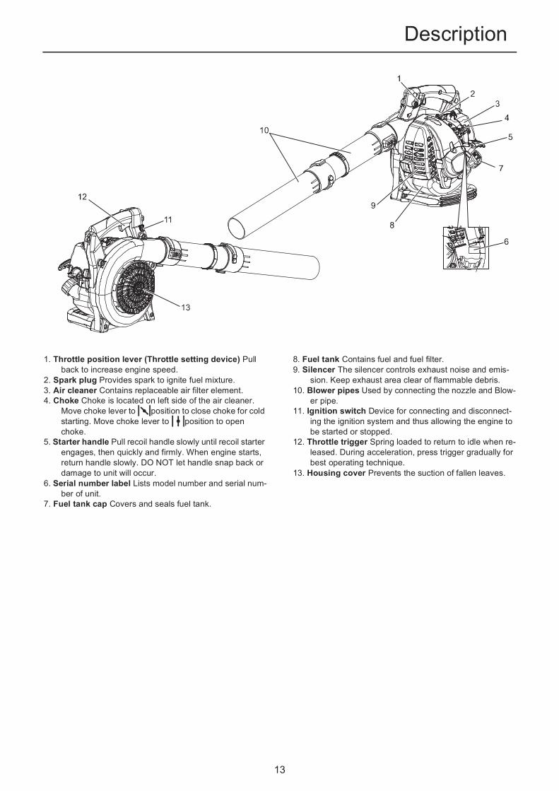
1. Throttle position lever (Throttle setting device) Pull back to increase engine speed.
2. Spark plug Provides spark to ignite fuel mixture. 3. Air cleaner Contains replaceable air filter element. 4. Choke Choke is located on left side of the air cleaner.
Move choke lever to position to close choke for cold starting. Move choke lever to position to open choke.
5. Starter handle Pull recoil handle slowly until recoil starter engages, then quickly and firmly. When engine starts, return handle slowly. DO NOT let handle snap back or damage to unit will occur.
6. Serial number label Lists model number and serial num-ber of unit.
7. Fuel tank cap Covers and seals fuel tank.
8. Fuel tank Contains fuel and fuel filter. 9. Silencer The silencer controls exhaust noise and emis-
sion. Keep exhaust area clear of flammable debris.10. Blower pipes Used by connecting the nozzle and Blow-
er pipe.11. Ignition switch Device for connecting and disconnect-
ing the ignition system and thus allowing the engine to be started or stopped.
12. Throttle trigger Spring loaded to return to idle when re-leased. During acceleration, press trigger gradually for best operating technique.
13. Housing cover Prevents the suction of fallen leaves.

14
Before you startBefore you start
Assembly
Install blower pipesPlace the blower upright on the ground or on a sturdy work sur-face.
1. Grasp the blower pipe and push the pipe over the blower dis-charge port.
2. Lock the blower pipe to the blower discharge port by rotating the pipe until a clicking sound is heard.
3. Grasp the nozzle and then push the nozzle over the blower pipe.
4. Lock the nozzle to the blower pipe by rotating the nozzle.
Remove blower pipes1. To detach the blower pipe, push the locking pin in and rotate
pipe anticlockwise. The hex wrench can be used.
WARNINGRead the operator's manual carefully to ensure that you assemble the product correctly.Never perform maintenance or assembly procedures with engine running.Using a product that has been incorrectly assembled could lead to an accident or serious injury.
1. Blower pipe 2. Blower discharge port
1. Blower pipe 2. Nozzle
IMPORTANTDo not operate the blower with only the blower pipe installed and without the nozzle properly installed.Do not install the nozzle directly to the blower discharge port.
IMPORTANTBlower pipe installation affects both blower balance and perfor-mance.
1. Blower pipe

15
Before you startPreparing the fuel
FuelFuel is a mixture of regular grade petrol and an air-cooled 2-stroke engine oil of reputable brand name.Minimum 89 Octane unleaded petrol is recommended. Do not use fuel containing methyl alcohol or more than 10 % of ethyl alcohol.Recommended mixture ratio; 50 : 1 (2 %) for ISO-L-EGD Standard (ISO/CD 13738), JASO FC,FD grade and Shindaiwa One oil.- Do not mix directly in engine fuel tank.- Avoid spilling petrol or oil. Spilled fuel should always be
wiped up.- Handle petrol with care, it is highly inflammable.- Always store fuel in approved container.
Fuel supplyAlways refuel in a well ventilated location. Do not pour fuel in-doors.Place the product and the refuelling tank on the ground when performing the refuelling operation. Do not refuel the product on the loading platform of a truck, or in other such places.Always ensure that the fuel level remains below the shoulder level of the fuel tank when refuelling.There is a difference in pressure between the fuel tank and the outside air. When refuelling, loosen the fuel tank cap slightly to eliminate the difference in pressure.Always wipe up any fuel spills.Move at least 3m away from where you refuelled before you start the engine.Keep the refuelling tank in a shaded area away from fire.
DANGERFuel is highly inflammable and there is a risk of fire if it is handled incorrectly. Carefully read and observe the precautions in the section of this manual titled "For safe use of your prod-uct".Once the refuelling is complete, securely tighten the fuel tank cap and do not forget to check that there are no leaks or discharges of fuel from the fuel pipe, fuel system grommets, or around the fuel tank cap. If you do find fuel leaks or discharges, stop using the product immediately and contact your shindaiwa dealer to have it repaired.If the fuel ignites, it could cause burns and fire.
CAUTIONThere is difference in pressure between the fuel tank and the outside air. When refuelling, loosen the fuel tank capslightly to eliminate the difference in pressure.
Otherwise, fuel may get spewed.
NOTEStored fuel ages. Do not mix more fuel than you expect use in thirty (30) days. Do not mix directly in fuel tank.
1. Fuel tank 2. Shoulder level

16
Engine operationEngine operat ion
Starting the engine
Starting a cold engine1. Ignition switch
Move ignition switch to "I"(START) position.2. Throttle Position Lever
Move throttle position lever to idle position " ".
3. ChokeMove choke to " " position.
4. Purge BulbPump purge bulb until fuel is visible and flows freely in theclear fuel tank return line.
5. Recoil StarterPlace the unit on a flat, clear area. Firmly grasp throttle gripwith left hand and rapidly pull recoil starter handle/rope untilengine fires , or maximum 5 pulls.
6. ChokeMove choke to " " position and if necessary, restart en-gine.If engine does not start after 5 pulls,repeat instructions 2-5.
7. Engine startAllow engine to warm up before use.
WARNINGWhen starting the engine, observe the precautions described from Page 4 in the section "For safe use of your prod-uct" to ensure that you operate the product correctly.Do not operate the product unless the housing cover and blower pipes are properly installed.Failure to observe the precautions could cause an accident or injury, or even lead to a fatality.
NOTEPull out the starter grip gently at first, and then more rapidly. Do not pull the starter rope out to more than 2/3 of its length.Do not let go of the starter grip as it returns.To start the engine, return the choke knob when you hear the first explosion-like sound and pull on the starter grip again. Be careful not to miss the first explosion-like sound.
1. Ignition switch 2. Throttle position lever
1. Choke 2. Purge bulb
1. Starter handle
1. Choke

17
Engine operationEngine warm-up
1. Once the engine starts, allow it to warm up for 2 to 3 minutes at idling (i.e. low speed).
2. Warming the engine helps to lubricate its internal workings more smoothly. Allow the engine to warm up fully, especially when it is cold.
3. Never run the engine without the blower pipes fitted.
Starting a warm engineThe starting procedure is the same as Cold Start except DO NOT close the choke.
1. Ignition SwitchMove ignition switch to "I" (START) position.
2. Throttle Position LeverMove throttle position lever to idle position( ).
3. Purge BulbPump purge bulb until fuel is visible and flows freely in theclear fuel tank return line.
4. Recoil StarterPlace the blower on a flat, clear area. Hold the blower firmlywith left hand and pull out the starter grip gently at first, andrapidly pull recoil starter handle/rope until engine fires. If en-gine does not start after 5 pulls, use cold start procedures.
Stopping the engine1. Throttle Position Lever
Release throttle trigger. Move throttle position lever forward toidle position and allow engine to return to idle before shuttingoff engine.
2. Move ignition switch to "O" (STOP) position.
1. Ignition switch 2. Throttle position lever
1. Purge bulb
1. Starter handle
1. Ignition switch3. Throttle trigger
2. Throttle position lever
WARNINGIf engine does not stop when ignition switch is moved to STOP position, close choke - position - to stall engine. Have your shindaiwa dealer repair ignition switch before using blower again.

18
OperationOperation
Operating blower
Read the Safety Section carefully.
1. Use only during appropriate hours.2. Allow the engine to warm up by pressing the throttle midway
for a few minutes.3. Control engine speed with throttle trigger, or for continuous
use, set engine speed with throttle position lever. Rotate throttle position lever forward for lower speed, back for high-er speed.
4. Use lower speed to blow dry grass and leaves from walks, patios and drives.
5. Additional speed may be necessary to clean leaves from a lawn or flowerbed.
6. Higher speed may be necessary to move gravel, dirt, snow, bottles or cans from a driveway, street, parking lot or stadi-um.
7. When working near a house, do not blow air towards open windows. Debris could be blown into window.
8. Using the longest pipe extension assures the air stream will reach the ground more efficiently.
9. Loosen or break up debris with a rake to make debris easier to move.
10. Dampen dusty areas before moving debris to reduce air-borne dust.
11. Always stop unit using stop engine procedure.
Throttle ControlThe "Cruise" function allows the operator to use a throttle po-sition lever for constant speed use without using the throttle trigger. This is useful for limiting the fatigue caused from hold-ing the throttle for extended periods of time.
Cruise FunctionUsing the right thumb, push the throttle position lever down untilthe desired r/min setting is reached.To bring RPM down to idle, push lever back up into original posi-tion.
WARNINGAlways wear safety glasses, hearing protection, face filter mask and take all safety precautions or serious personal in-jury may result. Do not point the blower pipe in the direction of people or pets.
IMPORTANTTo avoid engine damage due to over revving, do not block blower pipe opening.
NOTENever use a higher speed setting than necessary to perform a task. Remember, the higher the engine speed, the louder the blower noise. Minimize dust by using blower at lower speeds. Keep debris on your property. Be Smart - be a good neighbor.
1. Throttle position lever 2. Throttle trigger
1. Throttle position lever

19
Maintenance and careMaintenance and care
Servicing guidelines
Maintenance and care
Cleaning air filter
Tools required: 25-50 mm (1-2 in.) Cleaning brushParts required: Air filter
1. Close choke ( ). This prevents dirt from entering the car-burettor throat when the air filter is removed. Brush accumu-lated dirt from air cleaner area.
2. Remove air filter cover by loosening thumb screw.3. Remove and inspect pre-filter. If pre-filter is torn or otherwise
damaged, replace it with a new one.4. Brush dirt from inside cover.5. Clean pre-filter with soap and water. Let dry before reinstall-
ing.6. Inspect air filter element, If element is damaged or distorted,
replace it with a new one.7. Tap filter gently on a hard surface to dislodge debris from el-
ement or use compressed air from the inside to blow debris out and away from air filter element.
8. Install air filter element, pre-filter and cover in the reverse or-der of removal.
Area Maintenance Page Before use Monthly
Air filter Inspect/Clean/Replace 19 •
Fuel filter Inspect/Replace 20 •
Spark plug Inspect/Clean/Adjust/Replace 22 •
Carburettor Inspect 20 •
Cooling system Inspect/Clean 21 •
Exhaust system Inspect/Tighten/Clean 21 •
Starter Inspect - •
Fuel system Inspect - •
Screws, bolts and nuts Inspect/Tighten/Replace - •
IMPORTANTTime intervals are maximum. Actual use and your experience will determine the frequency of required maintenance.
If you have any questions or problems, please contact your shindaiwa dealer.
1. Air filter cover 2. Thumb screw
3. Pre-filter 4. Air filter element IMPORTANTDirect the air stream at the inside face of the filter only.
20
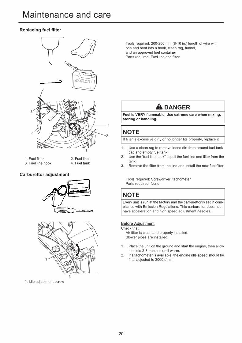
Maintenance and careReplacing fuel filter
Tools required: 200-250 mm (8-10 in.) length of wire withone end bent into a hook, clean rag, funnel,and an approved fuel containerParts required: Fuel line and filter
1. Use a clean rag to remove loose dirt from around fuel tank cap and empty fuel tank.
2. Use the "fuel line hook" to pull the fuel line and filter from the tank.
3. Remove the filter from the line and install the new fuel filter.
Carburettor adjustmentTools required: Screwdriver, tachometerParts required: None
Before AdjustmentCheck that:
Air filter is clean and properly installed.Blower pipes are installed.
1. Place the unit on the ground and start the engine, then allow it to idle 2-3 minutes until warm.
2. If a tachometer is available, the engine idle speed should be final adjusted to 3000 r/min.
1. Fuel filter3. Fuel line hook
2. Fuel line4. Fuel tank
DANGERFuel is VERY flammable. Use extreme care when mixing, storing or handling.
NOTEIf filter is excessive dirty or no longer fits properly, replace it.
NOTEEvery unit is run at the factory and the carburettor is set in com-pliance with Emission Regulations. This carburettor does not have acceleration and high speed adjustment needles.
1. Idle adjustment screw

21
Maintenance and careCooling system maintenance
Tools required: Cleaning brush, Wooden or plastic scraperParts required: None
Cleaning Grill
1. Brush accumulated debris from crankcase intake grill above the fuel tank.
Cleaning Cylinder Fins
1. Remove engine cover.2. Remove dirt and debris from cylinder fins and crankcase.3. Reassemble parts in reverse order.
Exhaust systemTools required: Soft metal brush, Hex WrenchParts required: None
Clean deposits and debris from silencer.Tighten silencer bolts.
Cleaning housing coverRemove dust of various sorts, including fallen leaves blocking the housing cover.
IMPORTANTTo maintain proper engine operating temperature, cooling air must pass freely through the cylinder fin area. This flow of air car-ries combustion heat away from the engine.Overheating and engine seizure can occur when:
Air intakes are blocked, preventing cooling air from reaching the cylinder,or
Dust and grass build up on the out side of the cylinder. This build-up insulates the engine and prevents the heat from leaving.Removal of cooling passage blockages or cleaning of cylinder fins is considered "Normal Maintenance". Any resultant failureattributed to lack of maintenance is not warranted.
1. Engine cover 2. Cylinder fins
IMPORTANTCarbon deposits in silencer will cause a drop in engine output and overheating.
1. Housing cover
IMPORTANTDo not remove the housing cover. If necessary, Please consult your dealer.

22
Maintenance and careCheck spark plug
Tools required: T-Wrench, Feeler gaugeParts required: Spark plug
1. Check plug gap. Correct gap is 0.6 mm to 0.7 mm.2. Inspect electrode for wear.3. Inspect insulator for oil or other deposits.4. Replace plug if needed and tighten to 15 N·m - 17 N·m (150
kgf·cm to 170 kgf·cm).a: 0.6 - 0.7 mm
IMPORTANTUse only NGK BPMR7A spark plug otherwise severe engine damage may occur.
23
Maintenance and care
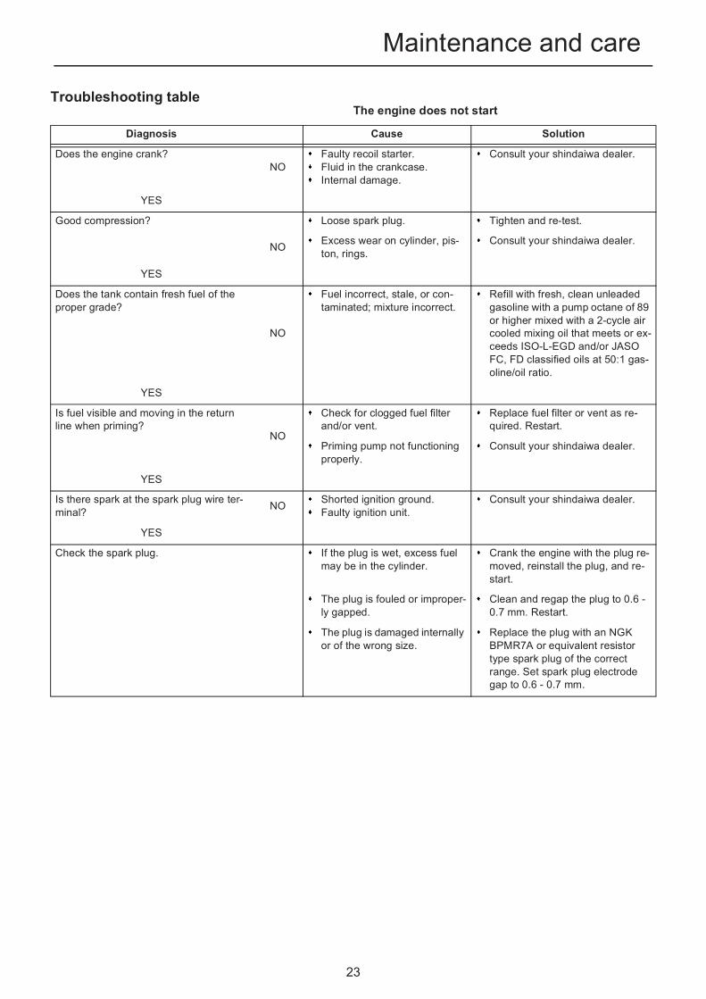
Troubleshooting tableThe engine does not start
Diagnosis Cause Solution
Does the engine crank?NO
Faulty recoil starter.Fluid in the crankcase.Internal damage.
Consult your shindaiwa dealer.
YES
Good compression?
NO
Loose spark plug. Tighten and re-test.
Excess wear on cylinder, pis-ton, rings.
Consult your shindaiwa dealer.
YES
Does the tank contain fresh fuel of the proper grade?
NO
Fuel incorrect, stale, or con-taminated; mixture incorrect.
Refill with fresh, clean unleaded gasoline with a pump octane of 89 or higher mixed with a 2-cycle air cooled mixing oil that meets or ex-ceeds ISO-L-EGD and/or JASO FC, FD classified oils at 50:1 gas-oline/oil ratio.
YES
Is fuel visible and moving in the return line when priming?
NO
Check for clogged fuel filter and/or vent.
Replace fuel filter or vent as re-quired. Restart.
Priming pump not functioning properly.
Consult your shindaiwa dealer.
YES
Is there spark at the spark plug wire ter-minal? NO Shorted ignition ground.
Faulty ignition unit.Consult your shindaiwa dealer.
YES
Check the spark plug. If the plug is wet, excess fuel may be in the cylinder.
Crank the engine with the plug re-moved, reinstall the plug, and re-start.
The plug is fouled or improper-ly gapped.
Clean and regap the plug to 0.6 -0.7 mm. Restart.
The plug is damaged internally or of the wrong size.
Replace the plug with an NGK BPMR7A or equivalent resistor type spark plug of the correct range. Set spark plug electrode gap to 0.6 - 0.7 mm.

24
Maintenance and careLow power output
Diagnosis Cause Solution
Is the engine overheating? Operator is overworking the unit.
Use a lower throttle setting.
Carburettor mixture is too lean. Consult your shindaiwa dealer.
Improper fuel ratio. Refill with fresh, clean unleaded gasoline with a pump octane of 89 or higher mixed with a 2-cycle air cooled mixing oil that meets or ex-ceeds ISO-L-EGD and/or JASO FC, FD classified oils at 50:1 gas-oline/oil ratio.
Fallen leaves or debris on housing cover.
Clean the housing cover.
Fan, fan cover, cylinder fins dirty or damaged.
Clean, repair or replace as neces-sary.
Carbon deposits on the piston or in the silencer.
Consult your shindaiwa dealer.
Engine is rough at all speeds. May also have black smoke and/or unburned fuel at the exhaust.
Clogged air cleaner element. Service the air cleaner element.
Loose or damaged spark plug. Tighten or replace.
Air leakage or clogged fuel line. Repair or replace fuel filter and/or fuel line.
Water in the fuel. Replace the fuel.
Piston seizure.Faulty carburettor and/or dia-phragm.
Consult your shindaiwa dealer.
Engine is knocking. Overheating condition. See above.
Improper fuel. Check fuel octane rating; check for presence of alcohol in the fuel. Re-fuel as necessary.
Carbon deposits in the com-bustion chamber.
Consult your shindaiwa dealer.

25
Maintenance and careAdditional problems
Diagnosis Cause Solution
Poor acceleration. Clogged air filter. Clean the air filter.
Clogged fuel filter. Replace the fuel filter.
Lean fuel/air mixture. Consult your shindaiwa dealer.
Idle speed set too low. Adjust 3000 r/min.
Engine stops abruptly. Fuel tank empty. Refuel.
Clogged fuel filter. Replace fuel filter.
Water in the fuel. Drain; replace with clean fuel.
Shorted spark plug or loose terminal.
Clean or replace spark plug, tight-en the terminal.
Ignition failure. Consult your shindaiwa dealer.
Piston seizure. Consult your shindaiwa dealer.
Engine difficult to shut off. Ground (stop) wire is discon-nected, or switch is defective.
Test and replace as required.
Overheating due to incorrect spark plug.
Idle engine until cool. Clean and regap the plug to 0.6 - 0.7 mm. Correct plug: NGK BPMR7A or equivalent resistor type spark plug of the correct range.
Overheated engine. Idle engine until cool.
Excessive vibration. Debris build-up in fan. Clean debris from fan as required.
Loose or damaged fan. Consult your shindaiwa dealer.
Loose or damaged engine mounts.
Tighten or replace engine mounts as required.
Engine overspeeding. Blower intake or discharge ports or blower pipe or nozzle are clogged with debris.
Inspect and remove debris.
Fan blades are missing or damaged.
Consult your shindaiwa dealer.
Checking and maintenance requires specialist knowledge. If you are unable to check and maintain the product or deal with a fault yourself, consult your shindaiwa dealer. Do not attempt to dismantle the product.Consult your shindaiwa dealer in the event of a problem that is not covered in the table above, or other such concerns.For spare parts and consumables, please use only genuine parts and designated products and components. Using parts from other manufacturers or non-designated components may result in a malfunction.
NOTESoft Start (See page 2) When starter grip cannot be pulled lightly, the trouble is diagnosed as failure of engine inside. Please consult your dealer.If disassembled inadvertently, it can cause injury.

26
Maintenance and care
Long-term storage(30 days or more)
1. Store unit in a dry, dust free place, out of the reach of chil-dren.
2. Place the ignition switch in the "O"(STOP) position.3. Remove accumulation of grease, oil, dirt and debris from ex-
terior of unit.4. Perform all periodic lubrication and services that are re-
quired.5. Tighten all screws and nuts.6. Drain the fuel tank completely and pull the recoil starter han-
dle several times to remove fuel from the carburettor.7. Remove the spark plug and pour 10mL of fresh, clean 2-
stroke engine oil into the cylinder through the spark plug hole.
8. Fit the spark plug. (Do not connect the spark plug cap. )9. Remove blower pipe assembly from unit.
WARNINGDuring operation the silencer - catalytic silencer and surrounding cover become hot. Always keep exhaust area clear of flammable debris during transportation or when storing, otherwise serious property damage or personal injury may result.
Do not store your unit for a prolonged period of time (30 days or longer) without performing protective storage maintenance which includes the following:
WARNINGDo not store where fuel fumes may accumulate or reach an open flame or spark.
1. Ignition switch
A. Place a clean cloth over the spark plug hole.
B. Pull the recoil starter handle 2-3 times to distribute the oil inside the engine.
C. Observe the piston location through the spark plug hole. Pull the recoil handle slowly until the piston reaches the top of its travel and leave it there.
1. Spark plug 2. Spark plug cap
Please contact your shindaiwa dealer in order to dispose of the product or its parts in compliance with national laws.

27
SpecificationsSpecif icat ions
These specifications are subject to change without notice.
EB221S
Mass (Dry, with blower pipes): kg 3.4
External dimensions (without pipes): Length Width Height
mmmmmm
325 230 330
Engine: Type Engine displacement Maximum power Engine speed at maximum engine power Recommended engine speed at full load
Recommended engine speed at idling Carburettor Ignition Spark plug Starter
cm3
kWr/minr/minr/minr/min
Air cooled 2-stroke single cylinder gasoline engine21.1 0.62 7500 7800 (with round straight nozzle)8100 (with flat straight nozzle)3000 Diaphragm type Flywheel magneto - CDI system NGK BPMR7A Recoil starter
Air volume: (ANSI/OPEI B175.2) m3/h 600 (with round straight nozzle)474 (with flat straight nozzle)
Max. air speed: (ANSI/OPEI B175.2) m/sec 63.9 (with round straight nozzle)72.4 (with flat straight nozzle)
Fuel:
Oil
Regular grade petrol. Minimum 89 Octane unleadedpetrol is recommended. Do not use fuel containingmethyl alcohol or more than 10 % of ethyl alcohol. Two stroke, air-cooled engine oil. ISO-L-EGD Stand-ard (ISO/CD 13738), JASO FC,FD grade and Shindai-wa One oil.
Ratio 50 : 1 (2%)
Tank Capacity: mL 600
Sound pressure level: (EN15503) (The sum of measured values and the as-
sociated uncertainty.)
LpAId
LpARa
uncertainty
dB(A)dB(A)dB(A)dB(A)
73.7 (with round straight nozzle)73.7 (with flat straight nozzle)90.5 (with round straight nozzle)89.7 (with flat straight nozzle)2.5
Sound power level: (EN15503) (The sum of measured values and the as-
sociated uncertainty.)
LwAId
LwARa
uncertainty
dB(A)dB(A)dB(A)dB(A)
87.9 (with round straight nozzle)87.8 (with flat straight nozzle)104.4 (with round straight nozzle)104.1 (with flat straight nozzle)2.5
Vibration: (EN15503) Ahv,eq
uncertainty
m/s2
m/s26.9 (with round straight nozzle)6.5 (with flat straight nozzle)5.0

28
Declaration of conformityDeclarat ion of conformity
The undersigned manufacturer:
YAMABIKO CORPORATION7-2 SUEHIROCHO 1-CHOMEOHME; TOKYO 198-8760JAPAN
This declaration of conformity is issued under the sole responsibility of the manufacturer.
Declares that the hereunder specified new unit:
POWER BLOWER
Brand: shindaiwaType: EB221S
Complies with:
* the requirements of Directive 2006/42/EC (use of harmonized standard EN 15503: 2009+ A2: 2015)
* the requirements of Directive 2014/30/EU (use of harmonized standard EN ISO 14982: 2009)
* the requirements of Directive 2000/14/EC
Conformity assessment procedure followed ANNEX V
Measured sound power level : 102 dB(A)
Guaranteed sound power level : 105 dB(A)
Serial Number 36001001 and up
Tokyo, January 1st, 2016
YAMABIKO CORPORATION The authorized representative in Europe who is authorized tocompile the technical file. Company: Atlantic Bridge Limited Address: Atlantic House, PO Box 4800,
Earley, Reading RG5 4GB, United Kingdom
Masayuki Kimura Mr. Philip WicksGeneral Manager Quality Assurance Dept.

29
X750-027 51 0
X750 190-030 2
2014
1Notes and rear cover
MEMORANDUM