operators manual - amazon s3 · this guide describes operation of the . prolec pme . lifting and...
TRANSCRIPT
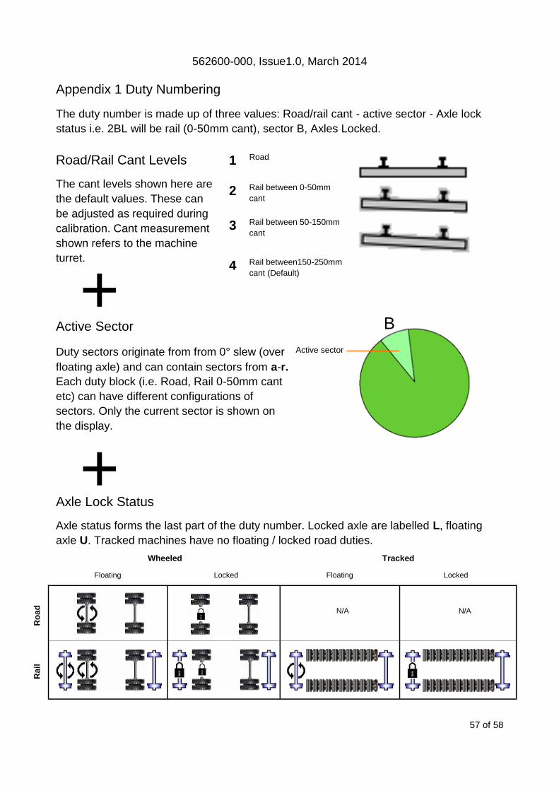
562600-000, Issue1.0, March 2014
PMERail Ultra Rated Capacity Controller
Machine Envelope Controller
Operators Manual
This guide describes operation of the
PROLEC PME LIFTING AND MACHINE ENVELOPE SAFETY SYSTEM FOR
CONSTRUCTION PLANT
Model covered : PART No. MODEL Ref
PMERail Ultra PMERail Ultra - RCC / MEC SYSTEM
PMERail Ultra RCC system has been designed for compliance with RIS-1530-PLT
Issue 4 and NR MLD/004
IMPORTANT : Before use, check the Engineering Acceptance certification and ma-
chine documentation to confirm if the Rated Capacity Controller, Adjacent Line
Open and Overhead Line Equipment limitations that may exist within the use of the
machine and / or the PMERail Ultra system.
Prolec supports a nationwide dealer network. Warranty claims, service work, technical
information and spare parts are available by contacting :
Prolec Ltd Telephone +44 (0) 1202 681190
25 Benson Road Fax +44 (0) 1202 67790
Nuffield Industrial Estate E-mail [email protected]
Poole Dorset BH17 0GB
DURING NORMAL OPERATION THE SAFE WORKING LOAD OF A CRANE SHOULD
NOT BE EXCEEDED. THEREFORE THE WARNING OF OVERLOAD SHOULD NOT
BE USED AS A NORMAL OPERATING FACILITY. IT SHOULD BE NOTED THAT
CERTAIN STATUTORY REQUIREMENTS DO NOT PERMIT THE SAFE WORKING
LOAD TO BE EXCEEDED EXCEPT FOR THE PURPOSE OF TESTING.
THIS RATED CAPACITY CONTROLLER (RCC) IS NOT SUITABLE FOR USE IN
EXPLOSIVE ATMOSPHERES. ADJUSTMENT BY UNAUTHORISED PERSONS WILL
INVALIDATE ANY WARRANTY OR CERTIFICATION SUPPLIED. IF A PROBLEM
ARISES WHICH CANNOT BE RECTIFIED USING THIS GUIDE, AUTHORISED
SERVICE SHOULD BE SOUGHT.
THIS DEVICE IS CERTIFIED TO MEET CURRENT UK & EC SAFETY REGULATIONS
FOR LIFTING OPERATIONS.
Any alterations or modifications to machine components which affect this system and any
system component failure must be reported to Prolec Ltd or via the machine convertor/
service agreement holder. This manual must be kept with the product and be passed on
to any subsequent user of the product.
Whilst every effort has been made to ensure the accuracy of the information supplied in
this manual, Prolec Ltd cannot be held responsible for any errors or omissions.
Manufacturers original instructions.
Table of contents
1 Use of this Document 7
2 Notices 7
3 System Identification 8
4 Operating and Restriction Situation Recommendations 9
4.1 RCC - MEC Override 9
5 Operating Instructions 10
5.1 Power Up 10
5.2 Using the Display 11
5.3 User Login 12
5.4 User Logout 13
5.5 Supervisor Keyswitch 13
6 Top Menu 13
7 Rated Capacity Controller 14
7.1 Introduction 14
7.2 Operation within the Safe Working Load 15
7.3 Barred, Duties, Warnings and Interlocks 15
7.3 Approach to Overload 15
7.5 Stability Control Overload 16
7.5.1 Hydraulic Limit Control 16
7.6 Overload / Hydraulic Limitation Control Override 17
7.6.1 Soft Override 17
7.6.2 Master Override Key Switch 17
Table of contents continued
7.7 Lift Mode Menu 18
7.7.1 Lifting Point Selection 18
7.7.2 Lifting Mode - Non Lifting Mode 19
7.7.3 Tandem Lifting Mode 20
7.7.4 LUL Lifting Mode 21
7.8 Lifting Duty Safety Factors 22
7.9 Load Chart Menu 23
7.10 Working Area Indication 24
7.11 In Gauge Indicator 25
8 Envelope Monitoring 26
8.1 Height Limit 26
8.1.1 Height Limits Menu 27
8.1.2 Height Limit Setting - Known Height 28
8.1.3 Height Limit Setting - Using Current Highest Point 29
8.1.4 Machine Envelope Controller (MEC) - Height 30
8.2 Slew Limit 31
8.2.1 Slew Limits Menu 31
8.2.2 Virtual wall limit - Dial in a Value 32
8.2.3 Virtual Wall Limit Setting - Manually Set a Limit 34
8.2.4 Machine Envelope Controller (MEC) - Virtual Wall
PMERail Ultra
36
8.2.4.1 PMERail Ultra Virtual Wall Limitation Control 36
8.2.4.2 Machine Envelope Controller (MEC) - Virtual Wall 37
8.3 Equipment Position Measurement 38
Table of contents continued
9 System Messages 39
9.1 On Screen Safety Messages 39
9.2 On Screen Component Error Messages 40
9.3 On Screen ALO Component Error Messages 41
9.4 LED and Internal Alarm Warnings 42
10 Maintenance 42
11 Test / Diagnostics 43
11.1 Relay Function Test 43
11.2 Sensor Information 44
11.3 Blue and Amber lamp, Alarm and LED function 44
12 System Information 45
13 Display Settings 46
13.1 Day / Night Mode 46
13.2 Select Display Machine 47
13.3 Select Safe Working Area Indication 47
13.4 Select Language 47
13.5 Select Background Colour 48
14 User Login 48
14.1 User Login Setup 48
14.1.1 Add New User to Login 49
Table of contents continued
14.1.2 Edit User Details 50
14.1.3 Select User to Delete 51
14.1.4 Edit User Access Code 51
14.1.5 Enable / Disable Users 52
15 Taking Product out of Operation 52
16 Service and Repair 52
16.1 Maintenance Review 52
17 Data Logger 53
18 System Diagram 54
19 Definitions / Glossary 55
20 Amendment / Revision Record 56
Appendix 1 Duty Numbering 57
Appendix 2 Interlocks 58

562600-000, Issue1.0, March 2014
7 of 58
1 Use of this Document
This user guide is intended for persons familiar with the use of construction plant under-
taking lifting operations.
2 Notices
Adjustment by unauthorised persons will invalidate any warranty or certifi-
cation supplied. If an error condition is displayed which cannot be recti-
fied using this guide, halt any operation, seek authorised service immedi-
ately and do not continue operation until the fault has been remedied.
WARNING denotes information about particular risks which may be
generated by certain applications, by using certain fittings, and
about additional protective measures which are necessary for such
applications.
Caution, care, risk situation
HAZARD Actions that can lead to serious injury or death

562600-000, Issue1.0, March 2014
8 of 58
3 System Identification
The PMERail Ultra system provides two primary safety functions
1. Lifting Stability
2. Machine Envelope Monitoring
Both safety functions are achieved through real time monitoring some
or all of the machine’s moving parts ( booms, other articulations, turret
etc ) and its environment ( ground pitch and inclination, load etc) and
actively determining the safety of the current operation where appropri-
ate limits have been set.
The Lifting Stability function falls into a single class
Rated Capacity Controllers (RCC) prevent instability when the ma-
chine is involved in lifting operations. This is achieved by hydrauli-
cally stopping unsafe movements of the machine which could
cause the machine to tip.
The Machine Envelope Monitoring function has a single class
Machine envelope controllers (MEC) prevent movements that
would bring parts of the machine into hazardous areas, most nota-
bly height restrictions when working under Overhead Line Equip-
ment and in an Adjacent Line Open situation.
562600-000, Issue1.0, March 2014
9 of 58
4 Operating and Hazard Situation Recommendations
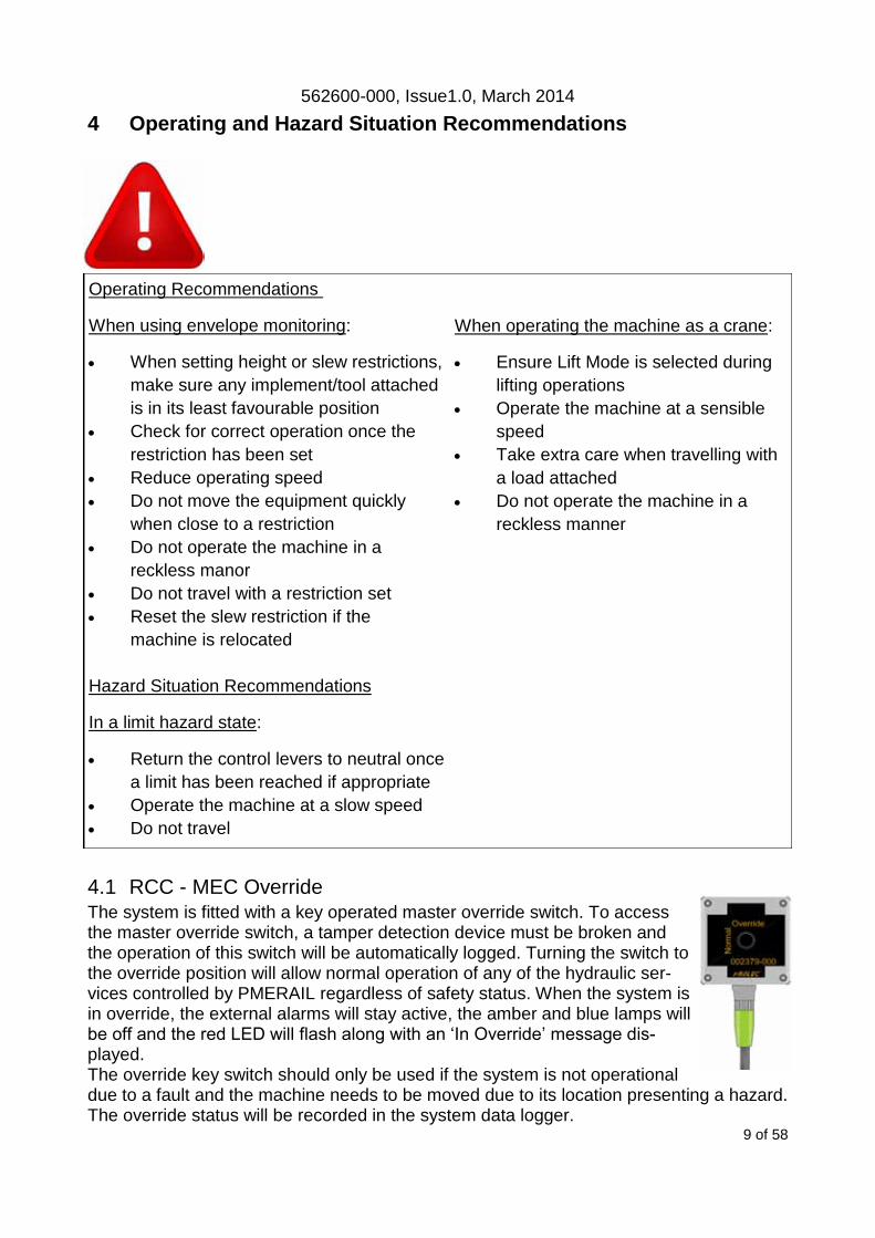
4.1 RCC - MEC Override The system is fitted with a key operated master override switch. To access the master override switch, a tamper detection device must be broken and the operation of this switch will be automatically logged. Turning the switch to the override position will allow normal operation of any of the hydraulic ser-vices controlled by PMERAIL regardless of safety status. When the system is in override, the external alarms will stay active, the amber and blue lamps will be off and the red LED will flash along with an ‘In Override’ message dis-played. The override key switch should only be used if the system is not operational due to a fault and the machine needs to be moved due to its location presenting a hazard. The override status will be recorded in the system data logger.
Operating Recommendations
When using envelope monitoring:
When setting height or slew restrictions,
make sure any implement/tool attached
is in its least favourable position
Check for correct operation once the
restriction has been set
Reduce operating speed
Do not move the equipment quickly
when close to a restriction
Do not operate the machine in a
reckless manor
Do not travel with a restriction set
Reset the slew restriction if the
machine is relocated
Hazard Situation Recommendations
In a limit hazard state:
Return the control levers to neutral once
a limit has been reached if appropriate
Operate the machine at a slow speed
Do not travel
When operating the machine as a crane:
Ensure Lift Mode is selected during
lifting operations
Operate the machine at a sensible
speed
Take extra care when travelling with
a load attached
Do not operate the machine in a
reckless manner
562600-000, Issue1.0, March 2014
10 of 58
5 Operating Instructions
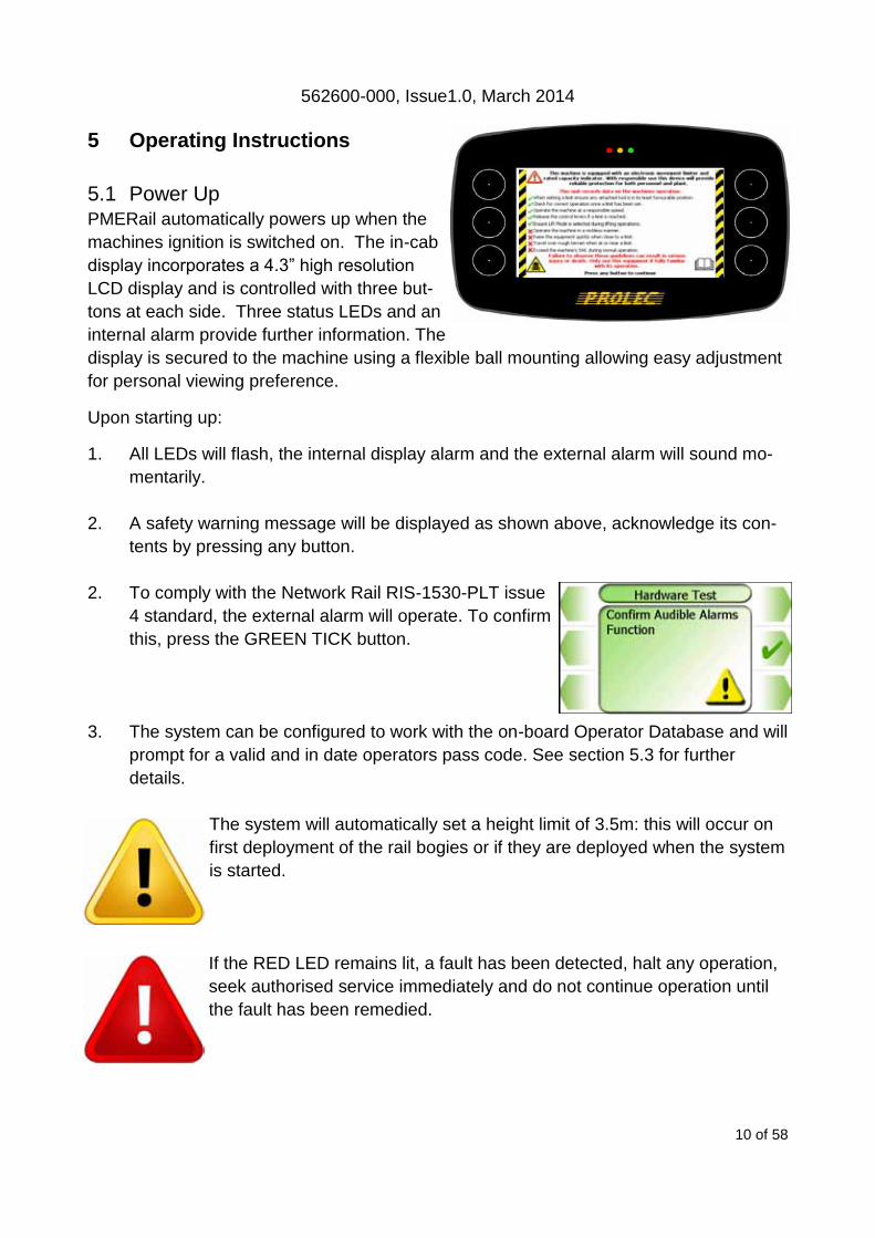
5.1 Power Up PMERail automatically powers up when the
machines ignition is switched on. The in-cab
display incorporates a 4.3” high resolution
LCD display and is controlled with three but-
tons at each side. Three status LEDs and an
internal alarm provide further information. The
display is secured to the machine using a flexible ball mounting allowing easy adjustment
for personal viewing preference.
Upon starting up:
1. All LEDs will flash, the internal display alarm and the external alarm will sound mo-
mentarily.
2. A safety warning message will be displayed as shown above, acknowledge its con-
tents by pressing any button.
2. To comply with the Network Rail RIS-1530-PLT issue
4 standard, the external alarm will operate. To confirm
this, press the GREEN TICK button.
3. The system can be configured to work with the on-board Operator Database and will
prompt for a valid and in date operators pass code. See section 5.3 for further
details.
The system will automatically set a height limit of 3.5m: this will occur on
first deployment of the rail bogies or if they are deployed when the system
is started.
If the RED LED remains lit, a fault has been detected, halt any operation,
seek authorised service immediately and do not continue operation until
the fault has been remedied.
562600-000, Issue1.0, March 2014
11 of 58
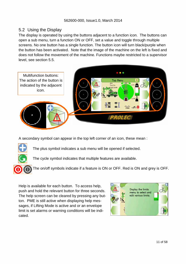
5.2 Using the Display
The display is operated by using the buttons adjacent to a function icon. The buttons can
open a sub menu, turn a function ON or OFF, set a value and toggle through multiple
screens. No one button has a single function. The button icon will turn black/purple when
the button has been activated. Note that the image of the machine on the left is fixed and
does not follow the movement of the machine. Functions maybe restricted to a supervisor
level, see section 5.5.
A secondary symbol can appear in the top left corner of an icon, these mean :
The plus symbol indicates a sub menu will be opened if selected.
The cycle symbol indicates that multiple features are available.
The on/off symbols indicate if a feature is ON or OFF. Red is ON and grey is OFF.
Help is available for each button. To access help,
push and hold the relevant button for three seconds.
The help screen can be cleared by pressing any but-
ton. PME is still active when displaying help mes-
sages, if Lifting Mode is active and or an envelope
limit is set alarms or warning conditions will be indi-
cated.
Multifunction buttons:
The action of the button is
indicated by the adjacent
icon.
562600-000, Issue1.0, March 2014
12 of 58
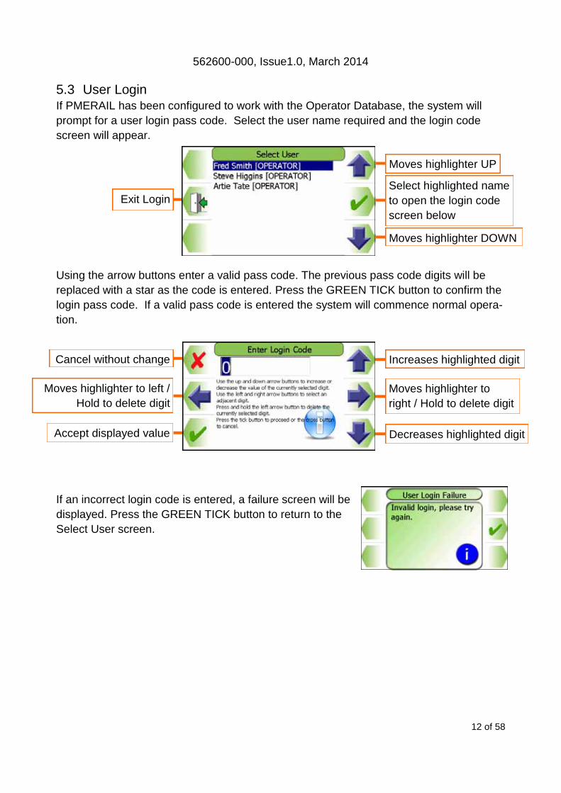
5.3 User Login If PMERAIL has been configured to work with the Operator Database, the system will
prompt for a user login pass code. Select the user name required and the login code
screen will appear.
Using the arrow buttons enter a valid pass code. The previous pass code digits will be
replaced with a star as the code is entered. Press the GREEN TICK button to confirm the
login pass code. If a valid pass code is entered the system will commence normal opera-
tion.
If an incorrect login code is entered, a failure screen will be
displayed. Press the GREEN TICK button to return to the
Select User screen.
Moves highlighter UP
Moves highlighter DOWN
Select highlighted name
to open the login code
screen below
Exit Login
Increases highlighted digit
Decreases highlighted digit Accept displayed value
Cancel without change
Moves highlighter to
right / Hold to delete digit
Moves highlighter to left /
Hold to delete digit
562600-000, Issue1.0, March 2014
13 of 58
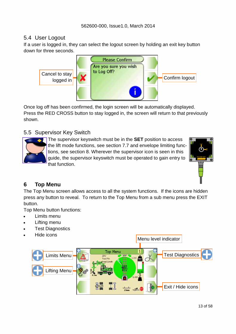
5.4 User Logout If a user is logged in, they can select the logout screen by holding an exit key button
down for three seconds.
Once log off has been confirmed, the login screen will be automatically displayed.
Press the RED CROSS button to stay logged in, the screen will return to that previously
shown.
5.5 Supervisor Key Switch
The supervisor keyswitch must be in the SET position to access
the lift mode functions, see section 7.7 and envelope limiting func-
tions, see section 8. Wherever the supervisor icon is seen in this
guide, the supervisor keyswitch must be operated to gain entry to
that function.
6 Top Menu The Top Menu screen allows access to all the system functions. If the icons are hidden
press any button to reveal. To return to the Top Menu from a sub menu press the EXIT
button. Top Menu button functions:
Limits menu
Lifting menu
Test Diagnostics
Hide icons
Confirm logout Cancel to stay
logged in
Limits Menu Test Diagnostics
Exit / Hide icons
Lifting Menu
Menu level indicator

562600-000, Issue1.0, March 2014
14 of 58
7 Rated Capacity Controller
7.1 Introduction PMERail has been designed to meet Network Rail requirements for the provision of rated
capacity indicators and ensures that the maximum lifting capacity over the range of a ma-
chine working envelope can be utilised. The system will default to Lifting Mode when
started up or when the bogies are deployed. See section 4 for operating advice when us-
ing construction plant as a crane. The blue lamp will indicate that Lifting Mode is active.
The SWL as displayed assumes that
the load is suspended directly below
the lifting point. The weight of the
tool or tools, if fitted, (e.g. Bucket ,
quick hitch etc) are included in the
SWL and LOH values if they were
taken into consideration when the
system was calibrated. The bucket
cylinder and control linkage is
assumed to be present.
Any alterations or modifications to
machine components which affect the
RCC must be reported to Prolec Ltd or
via the machine convertor/service
agreement holder.
6
7
5
1
14
4
8
3
13 12 11 10 9
4 2
1. Duty Indicator Appendix 1
Lifting point Section 7.11
Login name Section 5.3
2. Sector Indicator Appendix 1
3. Slew Angle Indicator Section 8.3.1
4. Safe Direction Indicator Section 8.3.1
5. Maximum Safe Working Load Section 7
6. SWL percentage Section 7
7. Load On Hook Section 7
8. Logging Indicator Section 18
9. Gradient Indicator Appendix 1
10. Cant Indicator Appendix 1
11. In Gauge Indicator Section 7.13
12. Rail Bogie Indicator Appendix 1
13. Axle Lock Inhibit Status Appendix 1, 2
14. Lifting point Height/Radius Section 7.11, 8.3
562600-000, Issue1.0, March 2014
15 of 58
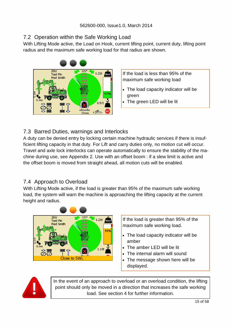
7.2 Operation within the Safe Working Load With Lifting Mode active, the Load on Hook, current lifting point, current duty, lifting point
radius and the maximum safe working load for that radius are shown.
7.3 Barred Duties, warnings and Interlocks A duty can be denied entry by locking certain machine hydraulic services if there is insuf-
ficient lifting capacity in that duty. For Lift and carry duties only, no motion cut will occur.
Travel and axle lock interlocks can operate automatically to ensure the stability of the ma-
chine during use, see Appendix 2. Use with an offset boom : if a slew limit is active and
the offset boom is moved from straight ahead, all motion cuts will be enabled.
7.4 Approach to Overload With Lifting Mode active, if the load is greater than 95% of the maximum safe working
load, the system will warn the machine is approaching the lifting capacity at the current
height and radius.
In the event of an approach to overload or an overload condition, the lifting
point should only be moved in a direction that increases the safe working
load. See section 4 for further information.
If the load is greater than 95% of the
maximum safe working load.
The load capacity indicator will be
amber
The amber LED will be lit
The internal alarm will sound
The message shown here will be
displayed.
If the load is less than 95% of the
maximum safe working load
The load capacity indicator will be
green
The green LED will be lit
562600-000, Issue1.0, March 2014
16 of 58
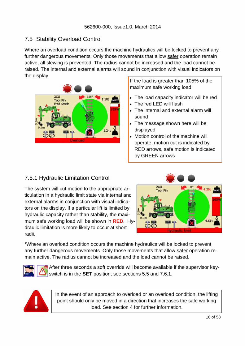
7.5 Stability Overload Control
Where an overload condition occurs the machine hydraulics will be locked to prevent any
further dangerous movements. Only those movements that allow safer operation remain
active, all slewing is prevented. The radius cannot be increased and the load cannot be
raised. The internal and external alarms will sound in conjunction with visual indicators on
the display.
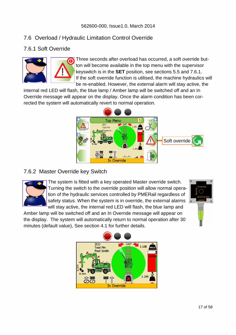
7.5.1 Hydraulic Limitation Control
The system will cut motion to the appropriate ar-
ticulation in a hydraulic limit state via internal and
external alarms in conjunction with visual indica-
tors on the display. If a particular lift is limited by
hydraulic capacity rather than stability, the maxi-
mum safe working load will be shown in RED. Hy-
draulic limitation is more likely to occur at short
radii.
*Where an overload condition occurs the machine hydraulics will be locked to prevent
any further dangerous movements. Only those movements that allow safer operation re-
main active. The radius cannot be increased and the load cannot be raised.
After three seconds a soft override will become available if the supervisor key-
switch is in the SET position, see sections 5.5 and 7.6.1.
In the event of an approach to overload or an overload condition, the lifting
point should only be moved in a direction that increases the safe working
load. See section 4 for further information.
If the load is greater than 105% of the
maximum safe working load
The load capacity indicator will be red
The red LED will flash
The internal and external alarm will
sound
The message shown here will be
displayed
Motion control of the machine will
operate, motion cut is indicated by
RED arrows, safe motion is indicated
by GREEN arrows
562600-000, Issue1.0, March 2014
17 of 58
7.6 Overload / Hydraulic Limitation Control Override
7.6.1 Soft Override
Three seconds after overload has occurred, a soft override but-
ton will become available in the top menu with the supervisor
keyswitch is in the SET position, see sections 5.5 and 7.6.1.
If the soft override function is utilised, the machine hydraulics will
be re-enabled. However, the external alarm will stay active, the
internal red LED will flash, the blue lamp / Amber lamp will be switched off and an In
Override message will appear on the display. Once the alarm condition has been cor-
rected the system will automatically revert to normal operation.
7.6.2 Master Override key Switch
The system is fitted with a key operated Master override switch.
Turning the switch to the override position will allow normal opera-
tion of the hydraulic services controlled by PMERail regardless of
safety status. When the system is in override, the external alarms
will stay active, the internal red LED will flash, the blue lamp and
Amber lamp will be switched off and an In Override message will appear on
the display. The system will automatically return to normal operation after 30
minutes (default value), See section 4.1 for further details.
Soft override

562600-000, Issue1.0, March 2014
18 of 58
7.7 Lift Mode Menu
The Lifting Mode menu has various features which may be available if config-
ured at installation. If only one lifting point has been calibrated, the lifting
point button will not be displayed.
7.7.1 Lifting Point Selection
PMERail can be configured for more than one lifting
point. If more than one lifting point has been cali-
brated, they will be manually selected via the lifting
point selection screen shown below. Use the arrow
buttons to select the required lifting point and con-
firm using the GREEN TICK button. The Supervisor keyswitch must be in the SET posi-
tion to access this feature, see section 5.5 for further information. Example lifting points
are shown in the listing. Always refer to the manufacturer/convertor instructions regarding
positioning of the lifting point during lifting operations. Altering the lifting point will not af-
fect the current duty selected, see Appendix 1.
Moves highlighter UP
Moves highlighter DOWN
Accept highlighted
lifting point
Exit to previous screen
Exit without change
Displays load chart(s)
Lifting point selection
Lift Mode selection
Lifting point Height
and Radius
Lifting point Name
562600-000, Issue1.0, March 2014
19 of 58
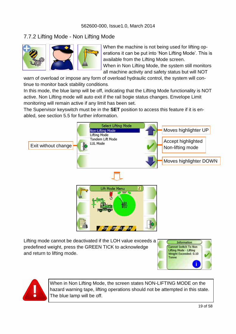
7.7.2 Lifting Mode - Non Lifting Mode
When the machine is not being used for lifting op-
erations it can be put into ‘Non Lifting Mode’. This is
available from the Lifting Mode screen.
When in Non Lifting Mode, the system still monitors
all machine activity and safety status but will NOT
warn of overload or impose any form of overload hydraulic control, the system will con-
tinue to monitor back stability conditions.
In this mode, the blue lamp will be off, indicating that the Lifting Mode functionality is NOT
active. Non Lifting mode will auto exit if the rail bogie status changes. Envelope Limit
monitoring will remain active if any limit has been set.
The Supervisor keyswitch must be in the SET position to access this feature if it is en-
abled, see section 5.5 for further information.
Lifting mode cannot be deactivated if the LOH value exceeds a
predefined weight, press the GREEN TICK to acknowledge
and return to lifting mode.
When in Non Lifting Mode, the screen states NON-LIFTING MODE on the
hazard warning tape, lifting operations should not be attempted in this state.
The blue lamp will be off.
Moves highlighter UP
Moves highlighter DOWN
Accept highlighted
Non-lifting mode Exit without change
562600-000, Issue1.0, March 2014
20 of 58
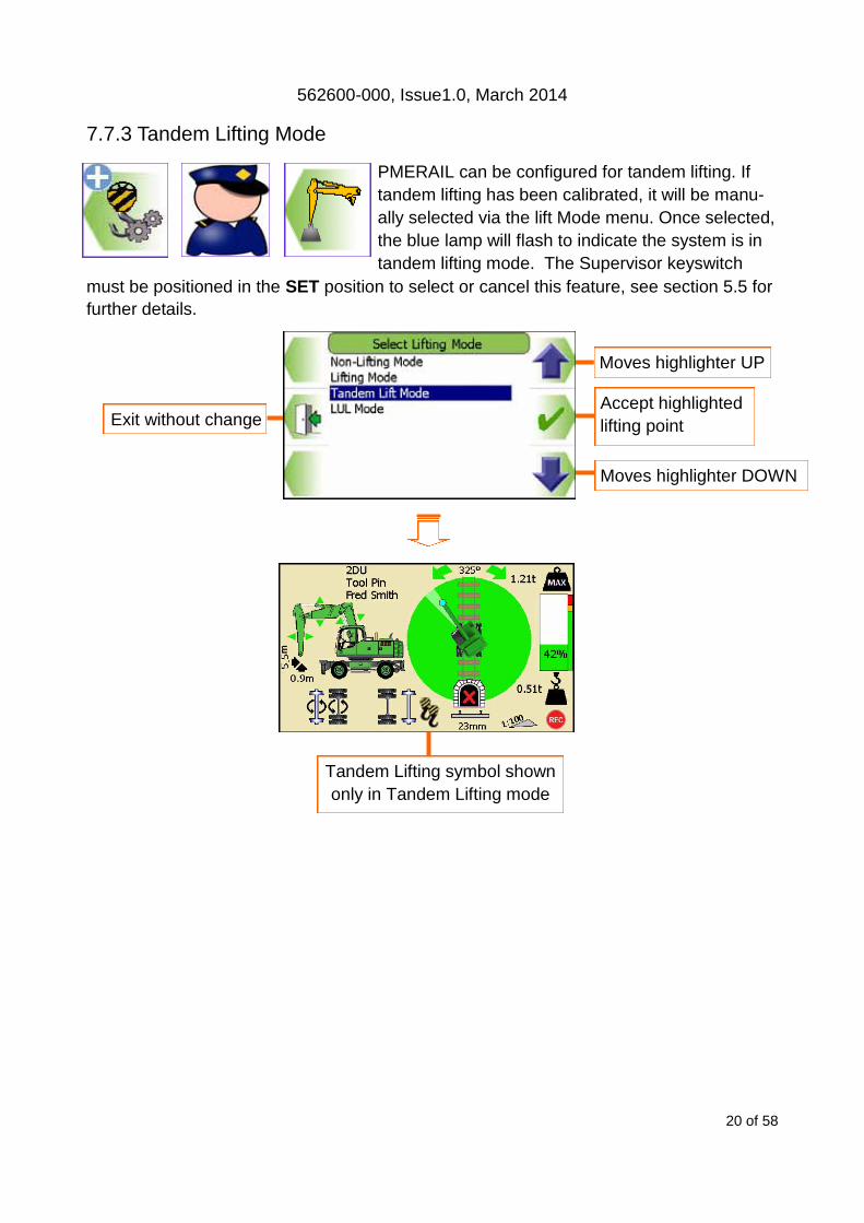
7.7.3 Tandem Lifting Mode
PMERAIL can be configured for tandem lifting. If
tandem lifting has been calibrated, it will be manu-
ally selected via the lift Mode menu. Once selected,
the blue lamp will flash to indicate the system is in
tandem lifting mode. The Supervisor keyswitch
must be positioned in the SET position to select or cancel this feature, see section 5.5 for
further details.
Moves highlighter UP
Moves highlighter DOWN
Accept highlighted
lifting point Exit without change
Tandem Lifting symbol shown
only in Tandem Lifting mode

562600-000, Issue1.0, March 2014
21 of 58
Moves highlighter UP
Moves highlighter DOWN
Accept highlighted
lifting mode Exit without change
7.7.4 LUL Lifting Mode
PMERail can be configured for LUL mode. If LUL
has been calibrated, it will be manually selected via
the lift Mode menu. The Supervisor keyswitch must
be positioned in the SET position to select or cancel
this feature, see section 5.5 for further details.
LUL symbol shown
only in LUL mode
562600-000, Issue1.0, March 2014
22 of 58
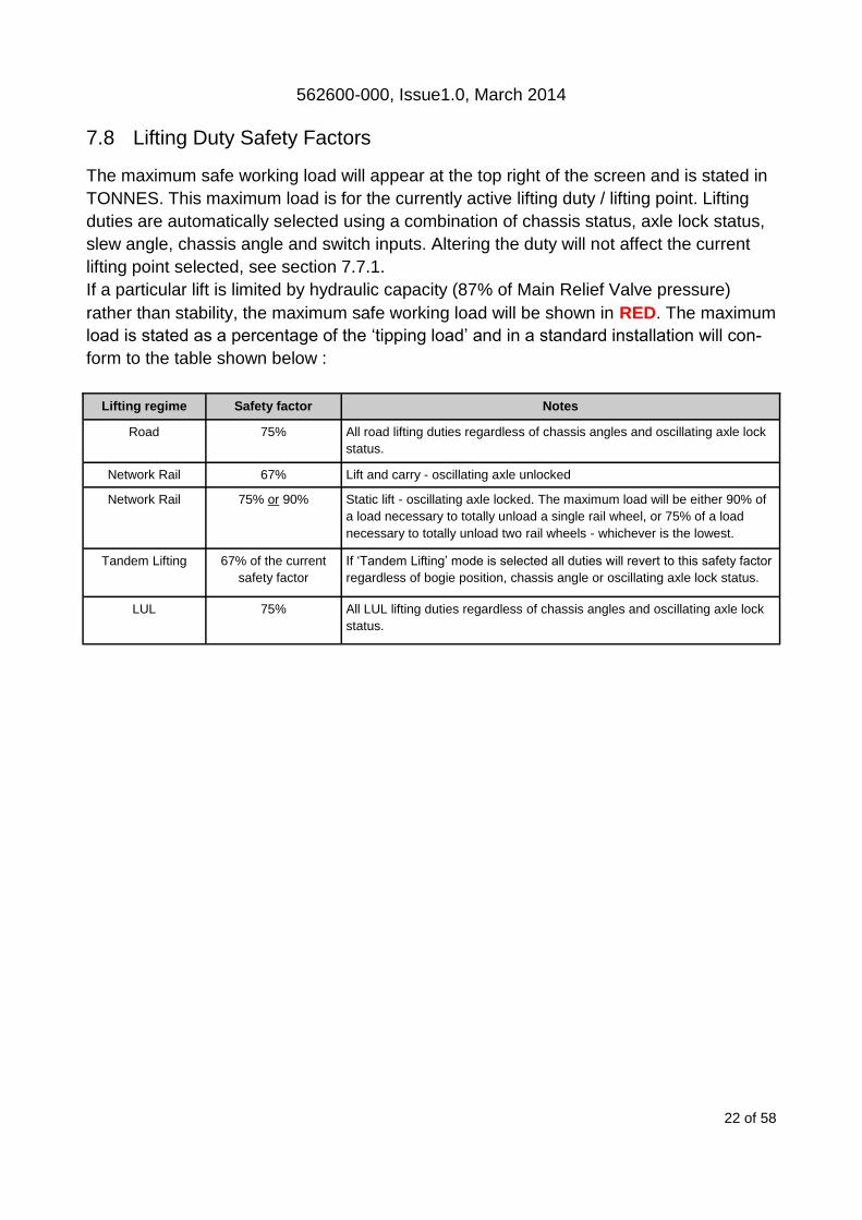
7.8 Lifting Duty Safety Factors
The maximum safe working load will appear at the top right of the screen and is stated in
TONNES. This maximum load is for the currently active lifting duty / lifting point. Lifting
duties are automatically selected using a combination of chassis status, axle lock status,
slew angle, chassis angle and switch inputs. Altering the duty will not affect the current
lifting point selected, see section 7.7.1.
If a particular lift is limited by hydraulic capacity (87% of Main Relief Valve pressure)
rather than stability, the maximum safe working load will be shown in RED. The maximum
load is stated as a percentage of the ‘tipping load’ and in a standard installation will con-
form to the table shown below :
Lifting regime Safety factor Notes
Road 75% All road lifting duties regardless of chassis angles and oscillating axle lock
status.
Network Rail 67% Lift and carry - oscillating axle unlocked
Network Rail 75% or 90% Static lift - oscillating axle locked. The maximum load will be either 90% of
a load necessary to totally unload a single rail wheel, or 75% of a load
necessary to totally unload two rail wheels - whichever is the lowest.
Tandem Lifting 67% of the current
safety factor
If ‘Tandem Lifting’ mode is selected all duties will revert to this safety factor
regardless of bogie position, chassis angle or oscillating axle lock status.
LUL 75% All LUL lifting duties regardless of chassis angles and oscillating axle lock
status.
562600-000, Issue1.0, March 2014
23 of 58
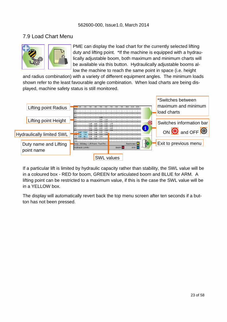
7.9 Load Chart Menu
PME can display the load chart for the currently selected lifting
duty and lifting point. *If the machine is equipped with a hydrau-
lically adjustable boom, both maximum and minimum charts will
be available via this button. Hydraulically adjustable booms al-
low the machine to reach the same point in space (i.e. height
and radius combination) with a variety of different equipment angles. The minimum loads
shown refer to the least favourable angle combination. When load charts are being dis-
played, machine safety status is still monitored.
If a particular lift is limited by hydraulic capacity rather than stability, the SWL value will be
in a coloured box - RED for boom, GREEN for articulated boom and BLUE for ARM. A
lifting point can be restricted to a maximum value, if this is the case the SWL value will be
in a YELLOW box.
The display will automatically revert back the top menu screen after ten seconds if a but-
ton has not been pressed.
Lifting point Radius
SWL values
Hydraulically limited SWL
*Switches between
maximum and minimum
load charts
Switches information bar
ON and OFF
Exit to previous menu
Lifting point Height
Duty name and Lifting
point name

562600-000, Issue1.0, March 2014
24 of 58
7.10 Safe Working Area Indication
Safe working area indication displays in real time the where a load can be safely moved
using the plan view. This feature will be available if it has been activated at calibration.
Any green area is safe and any hatched area is unsafe. The hatched area uses the LOH
value and the SWL value for all slew based duties to calculate the green and hatched
area. If a Virtual slew wall (section 8.2) has been set then this limit will be incorporated
into the hatched area.
This feature does not indicate duties automatically switched using proximity switches
such as extending sections or stabilisers.
With Safe Working Indication ON:
The Green area indicates the safe zone
The Hatched area indicates the hazard
zone

562600-000, Issue1.0, March 2014
25 of 58
In Gauge warning message
The GREEN TICK symbol indicates that the right and left corners of the
counterweight, bucket pin and the highest point of the machine are within the
W6a gauge dimensions. The In gauge button will now appear in the top
menu, press to lock slew left / right, boom up and down, artic up and down
and arm in and out. Press again to unlock these services
The RED CROSS symbol indicates that the machine is outside of the gauge
dimensions.
7.11 In Gauge Indicator
If the machine is on-rail, within the In Gauge and the oscillating axle is
unlocked, the In Gauge icon will turn from a RED CROSS to a GREEN TICK
and the In Gauge button will appear in the top menu, press to motion to cut all
services for safe travel.
WARNING The system is unaware of any addi-
tional implements / tools, see section 8.4.
Machines with front and rear oscillating axles will
indicate In Gauge when either the front or rear ax-
les are unlocked or when both are unlocked. In
gauge indication will not be available if both (front
and rear) axles are locked.
In Gauge dimensions are shown opposite.
Safe Directional indicators will be all RED when In Gauge
mode is active indicating motions are cut
Press to Lock or
unlock machine into
In Gauge mode.

562600-000, Issue1.0, March 2014
26 of 58
8 Envelope Monitoring
PMERail Ultra is configured for Machine Envelope Control
(MEC) only. MEC will warn and prevent equipment motion in a
limit state. MEC is achieved by interacting with the machines
hydraulics, this allows motion to be cut to any section of equip-
ment that has reached a restriction but allow other sections to
operate unhindered unless they too reach the set restriction, see section 8.4 for moni-
tored points on the machine. PMERail is NOT aware of any attachment fitted, therefore
where an attachment is in use, limits should be determined and set in accordance with
the safe system of work.
8.1 PMERail Ultra Height Limitation
PMERail Ultra complies with RIS-1530-PLT Issue 4 height limiting requirements. There-
fore a default height limit of 3.5m will activate automatically on start up if the bogies are
deployed or on their first deployment. Any height limit previously set will be replaced.
Care should be taken to test that the limit is set correctly. Observe the operational limita-
tions given in section 4.
Height Limiting
Exit to previous
menu
Slew Limiting

562600-000, Issue1.0, March 2014
27 of 58
8.1.1 Height Limit Menu
A height limit can be set by entering a known height
on the keypad or by manually moving the machine
to the desired limit.
Using the height Limits Menu, the height limit can be
switched ON and OFF (a Confirm Operation screen will
be displayed, see sections 8.1.2 to enter a known height
and section 8.1.3 for setting the limit by moving the ma-
chine.
Use with an offset boom : if a slew limit is active and the offset boom is moved from
straight ahead, all motion cuts will be enabled.
Enter a height
Set height limit using
current highest part of
equipment
Exit to previous menu
Switches height monitoring
ON and OFF
Current highest point. Only displayed if a
height limit is set.

562600-000, Issue1.0, March 2014
28 of 58
8.1.2 Height Limit Setting - Known Height
A known limit can be entered into the
display:
Step One
Press the ’Enter a value’ button
Step Two
Set a limit and press Green TICK to accept.
Enter a value
Exit to previous menu
Increases highlighted digit
Decreases highlighted digit Accept displayed value
Cancel without change
Moves highlighter to
right / Hold to delete digit
Moves highlighter to left /
Hold to delete digit
Once a height limit set, the internal alarm will sound and the RED
LED will light if the equipment exceeds the current limit. Always
check that the current limit activates at the set point. The restriction cannot
be deactivated if in the alarm state. Observe the operational limitations
given in section 4.
Height limit shown here
562600-000, Issue1.0, March 2014
29 of 58
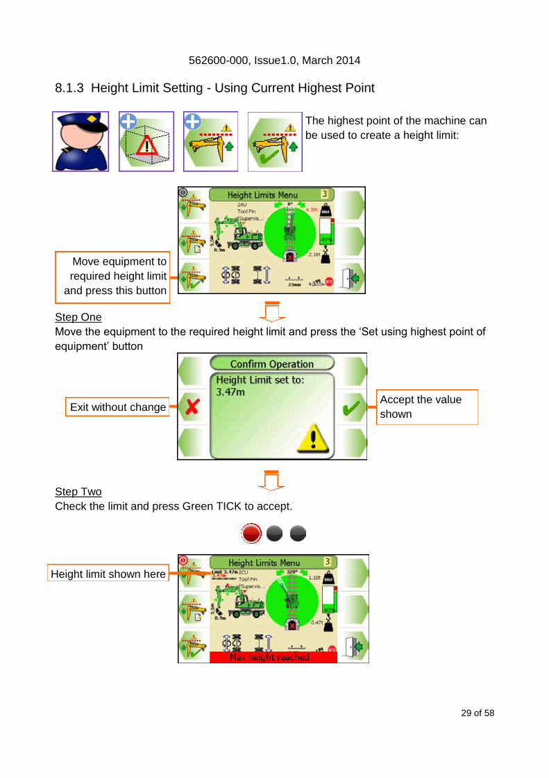
8.1.3 Height Limit Setting - Using Current Highest Point
The highest point of the machine can
be used to create a height limit:
Step One
Move the equipment to the required height limit and press the ‘Set using highest point of
equipment’ button
Step Two
Check the limit and press Green TICK to accept.
Move equipment to
required height limit
and press this button
Height limit shown here
Accept the value
shown Exit without change
562600-000, Issue1.0, March 2014
30 of 58
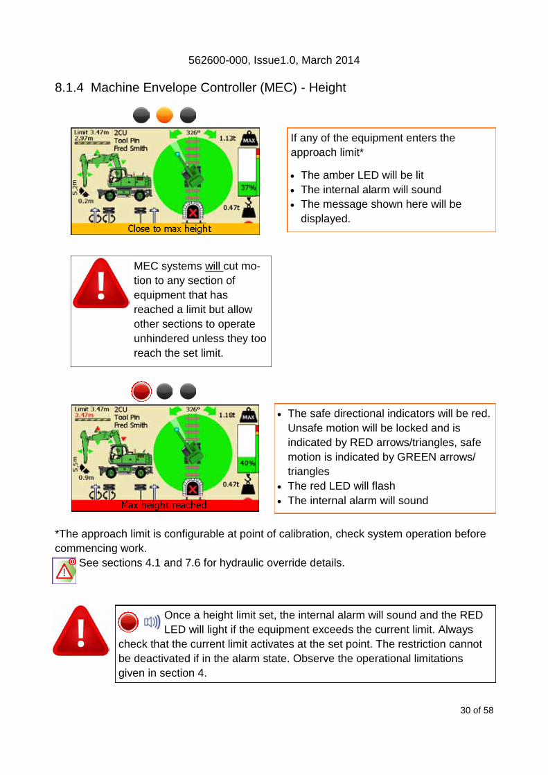
8.1.4 Machine Envelope Controller (MEC) - Height
*The approach limit is configurable at point of calibration, check system operation before
commencing work.
See sections 4.1 and 7.6 for hydraulic override details.
Once a height limit set, the internal alarm will sound and the RED
LED will light if the equipment exceeds the current limit. Always
check that the current limit activates at the set point. The restriction cannot
be deactivated if in the alarm state. Observe the operational limitations
given in section 4.
MEC systems will cut mo-
tion to any section of
equipment that has
reached a limit but allow
other sections to operate
unhindered unless they too
reach the set limit.
The safe directional indicators will be red.
Unsafe motion will be locked and is
indicated by RED arrows/triangles, safe
motion is indicated by GREEN arrows/
triangles
The red LED will flash
The internal alarm will sound
If any of the equipment enters the
approach limit*
The amber LED will be lit
The internal alarm will sound
The message shown here will be
displayed.

562600-000, Issue1.0, March 2014
31 of 58
8.2 Slew Limit
8.2.1 Slew Limits Menu
A virtual wall slew limit can be set entering a known
distance on the keypad or by moving the virtual wall
on the screen using the arrow buttons to the de-
sired limit. With a slew limit set, the screen will dis-
play a hatched area on the plan view.
A limit can be switched ON and OFF (a Confirm Opera-
tion screen will be displayed, see sections 8.2.3 to enter
a known value and section 8.2.4 for setting the limit by
manually moving the limit via the display.
Use with an offset boom: if a slew limit is active and the offset boom is moved from
straight ahead, all motion cuts will be enabled.
See section 8.2.2/3 for virtual wall setup and section 8.2.4.1 PMERail Ultra Virtual Wall
Limitation
Switches height monitoring
ON and OFF
Set virtual wall Exit to previous menu
Virtual wall limit

562600-000, Issue1.0, March 2014
32 of 58
8.2.2 Virtual Wall Limit Setting - Dial in a value
A virtual wall can be set on either side of the machine to a de-
sired distance by either dialling in a value.
The value displayed is measured from the centre of the machine.
Do not travel once a slew limit has been set.
Step One
Press the Set up a virtual wall button
Step two
Press the Keypad button
Step three
Select a side to set the virtual wall on
Continued on next page
Keypad button
Moves highlighter UP
Moves highlighter DOWN
Accept highlighted
side Exit without change
Virtual wall limit
Exit without change Set up a virtual wall

562600-000, Issue1.0, March 2014
33 of 58
Step four
Use the UP and DOWN arrows to increase and decrease the highlighted number. Use
the LEFT and RIGHT arrows to move the highlighter to the left and to the right. Press the
GREEN TICK to accept the displayed value.
Step five
Ensure the virtual wall is set correctly before pressing the GREEN TICK to accept and
use the limit displayed.
The Virtual wall will be shown on the main screen.
Once slew limits are set, the internal alarm will sound and the RED
LED will light if the equipment exceeds the limit. Always check that
the slew limit activates at the set point. The limit cannot be deactivated if in
the alarm state. Observe the operational limitations given in section 4. Do
not travel once a slew limit has been set.
Accept displayed value
Increases highlighted digit
Decreases highlighted digit Accept displayed value
Cancel without change
Moves highlighter to
right / Hold to delete digit
Moves highlighter to left /
Hold to delete digit
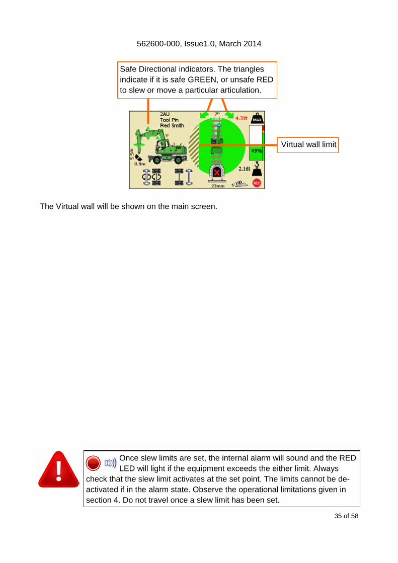
Safe Directional indicators. The triangles
indicate if it is safe GREEN, or unsafe RED
to slew or move a particular articulation.
Virtual wall limit
Virtual wall limit

562600-000, Issue1.0, March 2014
34 of 58
8.2.3 Virtual Wall Limit Setting - Manually set a limit
A virtual wall can be set on either side of the machine to a de-
sired distance by using the directional arrows to manually move
the limit.
The limit displayed is measured from the centre of the machine.
Do not travel once a slew limit has been set.
Step One
Press the Setup a virtual wall button
Step two
Use the Left and Right arrows to manually move the Virtual wall to the desired position.
Step three
Ensure the virtual wall is set correctly before pressing the GREEN TICK to accept and
use the displayed value.
Continued on next page
Setup a virtual wall
Moves the Virtual Wall
to the Left
Moves the Virtual Wall
to the Right
Accept displayed value
Virtual wall limit
Exit without change
562600-000, Issue1.0, March 2014
35 of 58
The Virtual wall will be shown on the main screen.
Once slew limits are set, the internal alarm will sound and the RED
LED will light if the equipment exceeds the either limit. Always
check that the slew limit activates at the set point. The limits cannot be de-
activated if in the alarm state. Observe the operational limitations given in
section 4. Do not travel once a slew limit has been set.
Safe Directional indicators. The triangles
indicate if it is safe GREEN, or unsafe RED
to slew or move a particular articulation.
Virtual wall limit

562600-000, Issue1.0, March 2014
36 of 58
8.2.4 Machine Envelope Controller (MEC) - Virtual Wall PMERail Ultra
8.2.4.1 PMERail Ultra Virtual Wall Limitation Control PMERail Ultra complies with NR MLD/004. slew limits requirements. Therefore with a vir-
tual wall slew limit active, as in addition to standard slew limit function (see section
8.2.4.2) the system will:
Care should be taken to test that the limit is set correctly. Observe the operational limita-
tions given in section 4.
Once slew limits are set, the internal alarm will sound and the RED
LED will light if the equipment exceeds the either limit. Always
check that the slew limit activates at the set point. The limits cannot be de-
activated if in the alarm state. Observe the operational limitations given in
section 4. Do not travel once a slew limit has been set.
Activate an amber lamp to show a slew limit is active
The slewing speed of the machine will be reduced to one of three possible states:
Linear speed at the tool point will be no greater than 2 m/s when MORE than 2m
(default) away from the set limit.
Linear speed at the tool point will be no greater than 1 m/s when LESS than 2m
(default) away from the set limit.
Linear speed at the tool point will be CONTROLLED by PMERail when LESS than
1m (default) away from the set limit. If the tool point reaches 1m (default) away
from the limit, PMERail will:
Motion cut slew at 1m (default) from the limit to allow PMERail to take over
slew control in the direction of slew travel only.
To move closer to the slew limit, the
slew joystick must be returned to the
neutral position then back towards
the limit. The warning message show
here will be displayed, linear speed at
the tool point will be no greater than 1
m/s in this state.
At the limit, motion will be stopped.
It will be possible to move away from a limit at anytime, the linear speed at the tool
point speed will be increased back up to no greater than 2 m/s.
The counterweight will not induce the 1m/s state even if it comes within 2m of the
limit.

562600-000, Issue1.0, March 2014
37 of 58
8.2.4.2 Machine Envelope Controller (MEC) - Virtual Wall
If the equipment reaches the limit, the appropriate motion will be controlled.
*The approach limit is configurable at point of calibration, check system operation before
commencing work.
See sections 7.6 for hydraulic override details.
Once slew limits are set, the internal alarm will sound and the RED
LED will light if the equipment exceeds the either limit. Always
check that the slew limit activates at the set point. The limits cannot be de-
activated if in the alarm state. Observe the operational limitations given in
section 4. Do not travel once a slew limit has been set.
MEC systems will cut mo-
tion to any section of
equipment that has
reached a limit but allow
other sections to operate
unhindered unless they too
reach the set limit.
The safe directional indicators will be red.
Unsafe motion will be locked and is
indicated by RED arrows/triangles, safe
motion is indicated by GREEN arrows/
triangles
The red LED will flash
The internal alarm will sound
If any of the equipment enters the
approach limit*
The amber LED will be lit
The internal alarm will sound
The message shown here will be
displayed.

562600-000, Issue1.0, March 2014
38 of 58
8.3 Equipment Position measurement
PMERail measures equipment pin positions using equipment mounted angle sensors. All
positions are corrected for chassis pitch (rail gradient), roll (rail cant) and slew angle. The
radius displayed on the operators screen represents the current lifting point and the
height represents the tool pin height. Shown without hitch.
= Equipment extremes
measured by the system
NB to account for extra
equipment and pipework
etc, both the bucket pin
and arm ram pin can use
an optional vertical safety
‘offset’ determined during
RCC set-up and
calibration.
5
Slew centre line
Radius
He
igh
t
Height Limit
Highest point
Slew Limit

562600-000, Issue1.0, March 2014
39 of 58
9 System Messages
9.1 On Screen Safety Messages
*The approach limit is configurable at point of calibration, check system operation before
commencing work.
Close to max height Highest point of equipment within *0.5m of set limit
Maximum height reached Equipment has reached set limit
ALO Controlling Slew PMERail is controlling slew movement toward the
slew limit
Close to Slew limit Equipment within *10 degrees or 0.5m of set limit
Slew Limit reached Equipment has reached set limit
Max Boom Angle reached Boom has reached a maximum set angle
Lifting barred in next Duty Insufficient lifting capacity in next duty
Lifting barred in this Duty Cannot lift in this duty
Maximum working cant reached Track cant reached limit (default = 150mm).
Maximum working gradient
reached Track gradient reached limit (default = 1 in 25).
Close to canted duty Insufficient lifting capacity in next duty
(Lift and carry duties only) No motion cut will occur
Fully Extend/Retract Counter-
weight Fully extend/retract counterweight
Offset boom is not straight Offset boom not straight.
Close to SWL 95 percent of the maximum safe working load
Overload 105 percent of the maximum safe working load
Hydraulic Limit Pressure in a ram/s is in excess of 87% of main relief
valve pressure
In Override Override has been activated (Soft override or master
Key)
In Gauge Lock Active In Gauge mode has been activated
562600-000, Issue1.0, March 2014
40 of 58
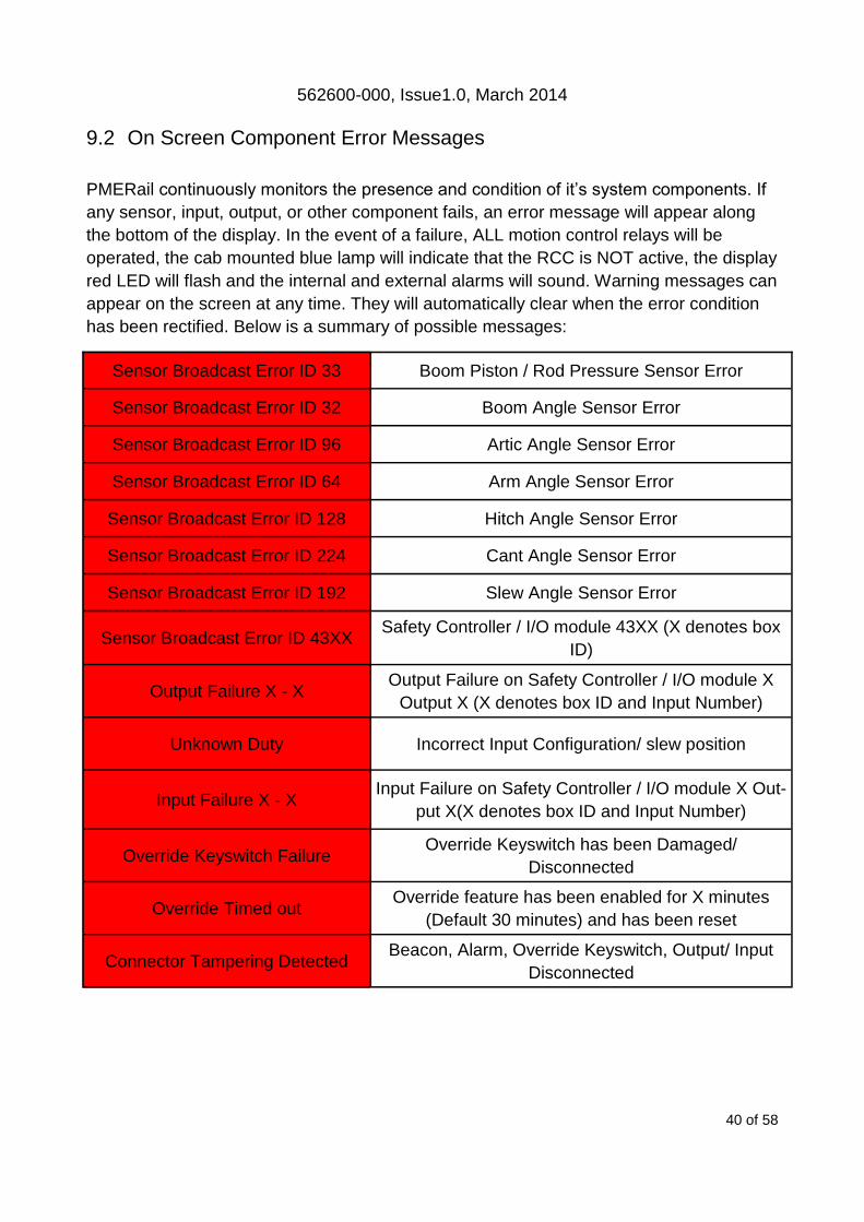
9.2 On Screen Component Error Messages
PMERail continuously monitors the presence and condition of it’s system components. If
any sensor, input, output, or other component fails, an error message will appear along
the bottom of the display. In the event of a failure, ALL motion control relays will be
operated, the cab mounted blue lamp will indicate that the RCC is NOT active, the display
red LED will flash and the internal and external alarms will sound. Warning messages can
appear on the screen at any time. They will automatically clear when the error condition
has been rectified. Below is a summary of possible messages:
Sensor Broadcast Error ID 33 Boom Piston / Rod Pressure Sensor Error
Sensor Broadcast Error ID 32 Boom Angle Sensor Error
Sensor Broadcast Error ID 96 Artic Angle Sensor Error
Sensor Broadcast Error ID 64 Arm Angle Sensor Error
Sensor Broadcast Error ID 128 Hitch Angle Sensor Error
Sensor Broadcast Error ID 224 Cant Angle Sensor Error
Sensor Broadcast Error ID 192 Slew Angle Sensor Error
Sensor Broadcast Error ID 43XX Safety Controller / I/O module 43XX (X denotes box
ID)
Output Failure X - X Output Failure on Safety Controller / I/O module X
Output X (X denotes box ID and Input Number)
Unknown Duty Incorrect Input Configuration/ slew position
Input Failure X - X Input Failure on Safety Controller / I/O module X Out-
put X(X denotes box ID and Input Number)
Override Keyswitch Failure Override Keyswitch has been Damaged/
Disconnected
Override Timed out Override feature has been enabled for X minutes
(Default 30 minutes) and has been reset
Connector Tampering Detected Beacon, Alarm, Override Keyswitch, Output/ Input
Disconnected

562600-000, Issue1.0, March 2014
41 of 58
9.3 On Screen ALO Component Error Messages
PMERail Max and Ultra continuously monitors the presence and condition of the ALO
slew components. If any sensor, input, output, or other component fails, an error
message will appear along the bottom of the display. In the event of a failure, ALL motion
control relays will be operated, the cab mounted blue lamp will indicate that the RCC is
NOT active, the display red LED will flash and the internal and external alarms will sound.
Warning messages can appear on the screen at any time. They will automatically clear
when the error condition has been rectified. Below is a summary of possible messages:
ALO CRC failure EEprom config CRC failure
ALO CAN failure Null Safety Controller pointer
ALO pilot failure Failed to initialise CAN
ALO invalid S/C Failed to initiate back drive controller class
ALO backdrive failure Failed to initiate pilot/brake controller class
ALO slew CANopen failure No slew CAN messages
ALO pitch/roll not detected No dual axis CAN messages
ALO backdrive CANopen failure No back drive controller CAN messages
ALO pilot CANopen failure No pilot controller CAN messages
ALO left feedback error Left controller feedback error > 10%
ALO right feedback failure Right controller feedback error > 10%
ALO pilot feedback failure Pilot controller feedback error > 10%
ALO brake feedback failure Both joysticks active at once
ALO illegal joysticks Left joystick input stuck low
ALO left joystick inactive error Right joystick input stuck low
ALO right joystick inactive error Left joystick input stuck high
ALO left joystick active error Right joystick input stuck high
ALO right joystick active error Left pressure switch input stuck low
ALO left pressure inactive error Right pressure switch input stuck low
ALO right pressure inactive error Left pressure switch input stuck high
ALO left pressure active error Right pressure switch input stuck high
ALO right pressure active error Failed to initialise axiomatic controller(s)
ALO controller failure No/missing CAN messages from Safety Controller
ALO S/C not reporting Brake controller feedback error > 10%
ALO slew DR Slew dual redundant error

562600-000, Issue1.0, March 2014
42 of 58
9.4 LED and Internal Alarm Warnings The table below shows the state of the three LEDs on the display and the internal alarm
with respect to system status.
10 Maintenance To be carried out on a daily basis. Full maintenance schedules are available in
the PMERail Maintenance Manual - Prolec Part Number 562010-003. The
maintenance instructions for the Rated Capacity Indicator fitted your RRV are to
be carried out in conjunction with the vehicle manufactures instruction hand-
book. Definition of terms used can be found in section 19. See section 11 for test / diagno-
sis features. If an failure is discovered which cannot be rectified using this guide, halt any
operation, seek authorised service immediately and do not continue operation until the fail-
ure has been remedied.
Continued on next page
LED and Internal Alarm status System status
Off
Start up, Power Down
Operational: System OK, no warnings, hazards, or errors
Warning: Approach to overload or envelope limit
Hazard; Overload or breach of an envelope limit
Maintenance: Engineering access active
Error: PME hardware/software error, or sensor failure
1 Hz
Continuous
8 Hz
Job Code Job Description
SFT1 Test overload alarm functionality audibly
SFT2 Test overload blue Lamp functionality visually
SFT3 Test overload amber Lamp functionality visually
SFT4 Test road axle interlock functionality disengages manual control
SFT5 Test rail axle interlock functionality disengages manual control
SFT6 Test travel interlock functionality disengages manual control
SFT7 Test all motion cuts to ensure functionality disengages manual control (I.e. Boom UP,
Arm OUT, Slew LEFT - RIGHT)
LT1 Test height limiter stops the highest section of equipment before the limit, see section
8 of the PMERail Operator Manual - Prolec Part Number 562600-000

562600-000, Issue1.0, March 2014
43 of 58
10 Maintenance continued
11 Test / Diagnostics
The system test function is available from the top menu screen. This feature
allows the system functions to be verified and basic trouble-shooting to be
performed. In this mode, the amber LED will flash to indicate the system is in
maintenance mode. The system will continue to monitor any active limits to
monitor machine safety status if in lift mode. Alarm conditions and warnings /
controls will be issued as normal.
The image shown is an example. The exact contents of the sensor list will depend on ma-
chine type and specification.
Job Code Job Description
LT2 Test slew limiter controls and stops machine before the limit, see section 8 of the
PMERail Operator Manual - Prolec Part Number 562600-000
SFC1 Check road axle icon shows correct state on display when operated
SFC2 Check rail axle(s) icon shows correct state on display when operated
SFC3 Check bogie deployment icon shows correct state on display when operated
SFC4 Check offset Boom shows correct state on display when operated
SFC5 Check LUL duty change shows correct state on display when operated
SFC6 Check stabiliser icon shows correct state on display when operated
SFC7 Check counterweight icon shows correct state on display when operated
Remedial Action: All jobs - Report any failure
Relay / LED test System information
Blue lamp, Alarm
and display LED test
Display options
Code protected ac-
cess to supervisor
features
Exit to previous menu

562600-000, Issue1.0, March 2014
44 of 58
11.1 Relay Function Test Select the unit required from the list
shown opposite.
11.2 Sensor Information
Displays the systems sensor information in bar or degrees. Use the Actual
column for direct comparison. The status column shows the health of each
sensor.
Press to highlight
connection / oper-
ate function
Exit to previous
menu
Motion cut outputs control hydraulic
services. See notation on screen for
individual assignment. Amber LED On
denotes output is On
Amber / Blue lamp / Motion Cut
outputs See notation on screen
for individual assignment. Amber
LED On denotes output is On
USB port. Not
supported in
this screen
CAN S and CAN D Communication
Link to Display and sensors. Amber
LED denotes output is On
Function Inputs. See notation on screen
for individual assignment. Amber LED
On denotes input is active
Link / Ign. Red LED
denotes unit failure
Override keyswitch
input. Amber LED On
denotes input is On
Exit to previous menu
Base Pitch = Pitch Angle
Base Roll = Pitch Angle
Boom Base Piston = Piston Pressure
Boom Base Rod = Rod Pressure
Boom AS7/10 = Boom angle
Artic AS7/10 = Artic angle
Arm AS7/10 = Arm angle
Platform = Slew angle
Linkage AS7 = Tipping link /Hitch Angle
562600-000, Issue1.0, March 2014
45 of 58
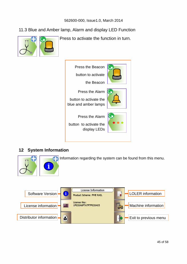
Press the Alarm
button to activate the
blue and amber lamps
Press the Alarm
button to activate the
display LEDs
Press the Beacon
button to activate
the Beacon
11.3 Blue and Amber lamp, Alarm and display LED Function
Press to activate the function in turn.
12 System Information
Information regarding the system can be found from this menu.
Software Version
License information
Distributor information
Machine information
Exit to previous menu
LOLER information
562600-000, Issue1.0, March 2014
46 of 58
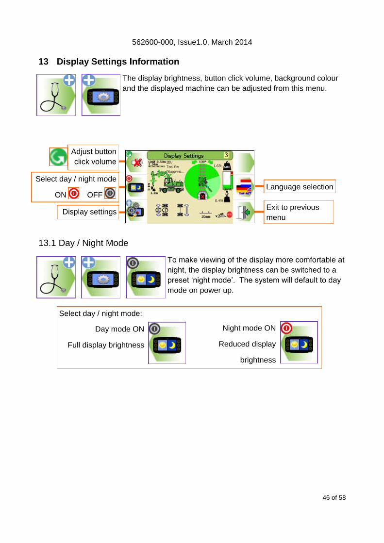
13 Display Settings Information
The display brightness, button click volume, background colour
and the displayed machine can be adjusted from this menu.
13.1 Day / Night Mode
To make viewing of the display more comfortable at
night, the display brightness can be switched to a
preset ‘night mode’. The system will default to day
mode on power up.
Language selection
Display settings
Adjust button
click volume
Select day / night mode
ON OFF
Exit to previous
menu
Night mode ON
Reduced display
brightness
Select day / night mode:
Day mode ON
Full display brightness
562600-000, Issue1.0, March 2014
47 of 58
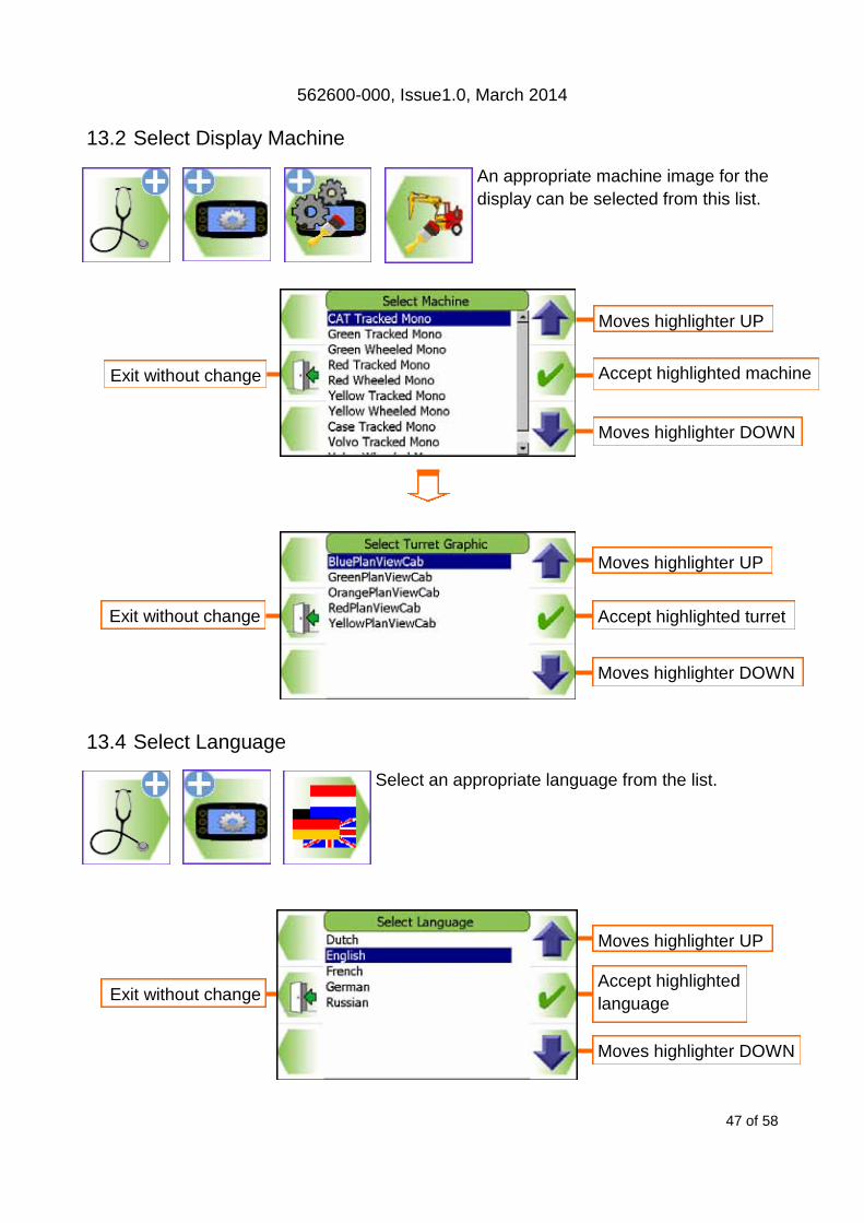
13.2 Select Display Machine
An appropriate machine image for the
display can be selected from this list.
13.4 Select Language
Select an appropriate language from the list.
Moves highlighter UP
Exit without change
Moves highlighter DOWN
Accept highlighted machine
Moves highlighter UP
Exit without change
Moves highlighter DOWN
Accept highlighted turret
Moves highlighter UP
Moves highlighter DOWN
Accept highlighted
language Exit without change

562600-000, Issue1.0, March 2014
48 of 58
13.5 Select Screen background colour
Different background colours, White,
blue, cream and grey are available.
Use this button to choose as required.
14 User Login
14.1 User Login manual Setup
Allows access to edit user details. Re-
quires supervisor access rights.
Edit user login code
Exit to previous menu Select user to delete
Add new user
Select user(s) to be dis-
played on login screen Select user to edit
562600-000, Issue1.0, March 2014
49 of 58
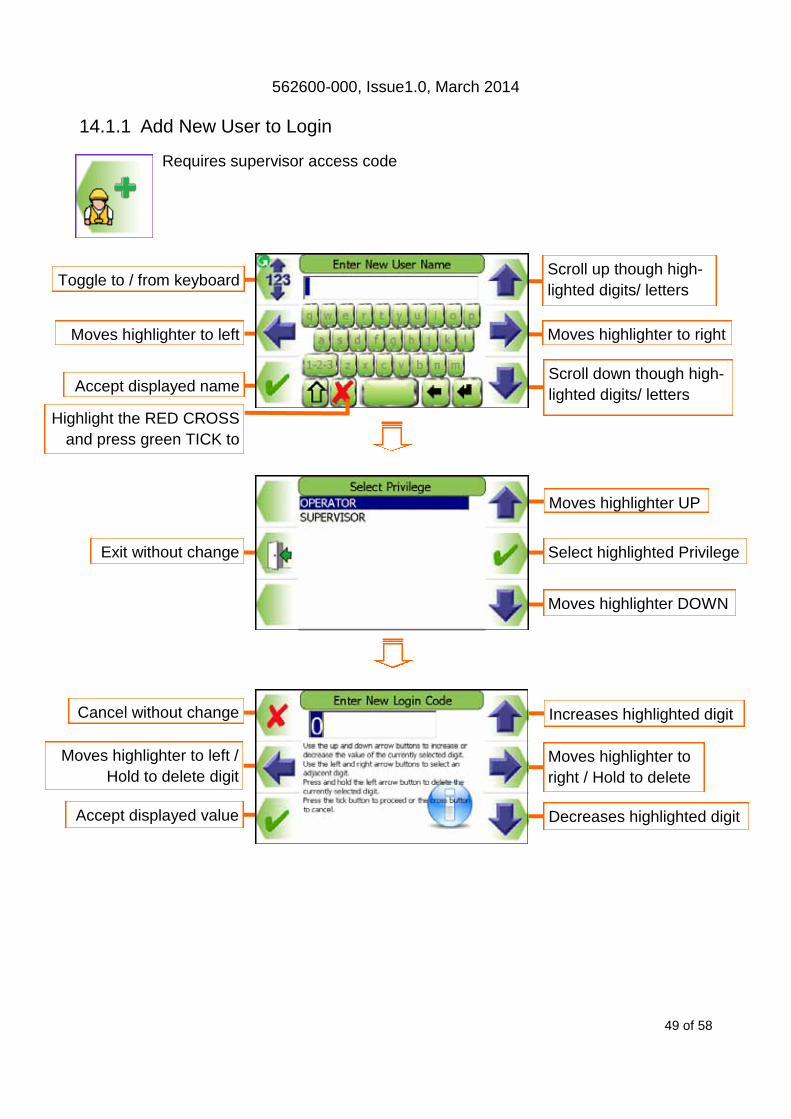
14.1.1 Add New User to Login
Requires supervisor access code
Moves highlighter UP
Exit without change
Moves highlighter DOWN
Select highlighted Privilege
Increases highlighted digit
Decreases highlighted digit Accept displayed value
Cancel without change
Moves highlighter to
right / Hold to delete
Moves highlighter to left /
Hold to delete digit
Scroll down though high-
lighted digits/ letters Accept displayed name
Toggle to / from keyboard
Moves highlighter to right Moves highlighter to left
Scroll up though high-
lighted digits/ letters
Highlight the RED CROSS
and press green TICK to
562600-000, Issue1.0, March 2014
50 of 58
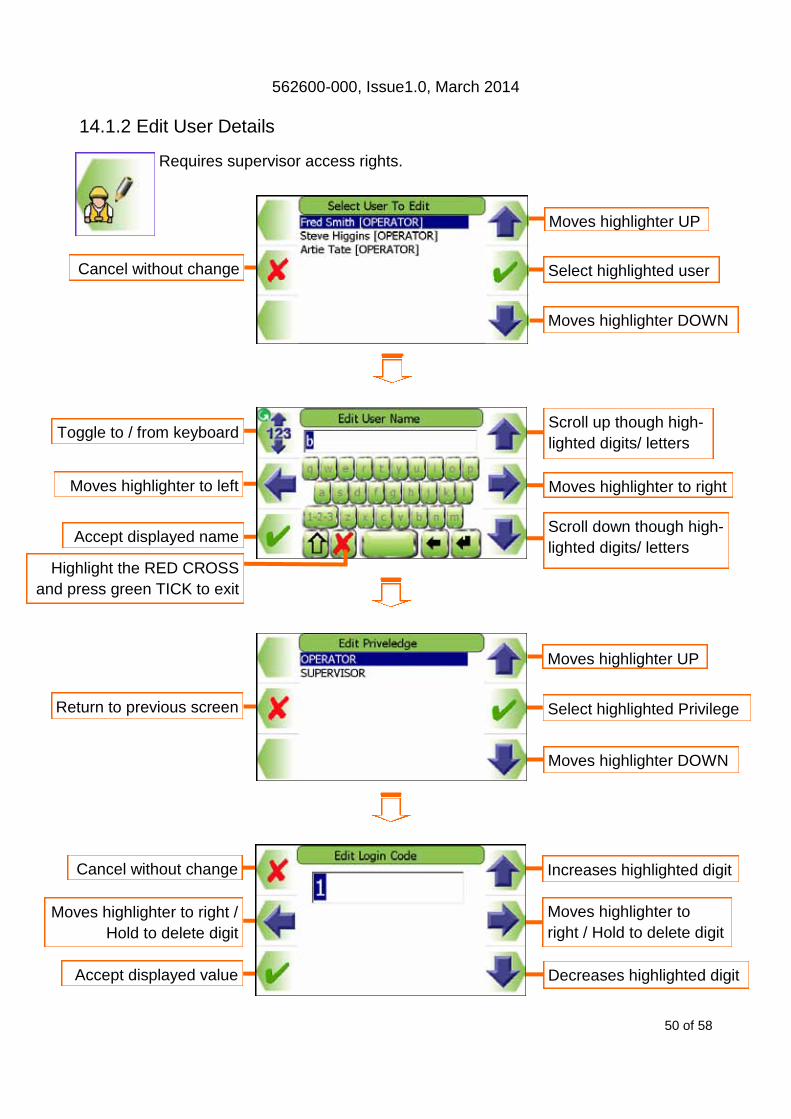
14.1.2 Edit User Details
Requires supervisor access rights.
Moves highlighter UP
Moves highlighter DOWN
Select highlighted user
Increases highlighted digit
Decreases highlighted digit
Moves highlighter to
right / Hold to delete digit
Moves highlighter UP
Moves highlighter DOWN
Select highlighted Privilege
Moves highlighter to right
Scroll down though high-
lighted digits/ letters
Scroll up though high-
lighted digits/ letters
Cancel without change
Cancel without change
Moves highlighter to right /
Hold to delete digit
Return to previous screen
Accept displayed name
Toggle to / from keyboard
Moves highlighter to left
Accept displayed value
Highlight the RED CROSS
and press green TICK to exit

562600-000, Issue1.0, March 2014
51 of 58
14.1.3 Select User to Delete
Requires supervisor access rights.
14.1.4 Edit User Login Code
Requires supervisor access rights.
Moves highlighter UP
Moves highlighter DOWN
Delete highlighted
Moves highlighter UP
Moves highlighter DOWN
Accept highlighted user
Increases highlighted digit
Decreases highlighted digit Accept displayed value
Cancel without change
Moves highlighter to right /
Hold to delete number
Moves highlighter to left /
Hold to delete digit
Exit without change
Exit without change

562600-000, Issue1.0, March 2014
52 of 58
14.1.5 Enable / Disable Users
Requires supervisor access rights
15 Taking Product out of Operation Prolec Limited is committed to complying with the upcoming European
Directive of RoHS (Restriction of Certain Hazardous Substances) and
WEEE (Waste from Electrical and Electronic Equipment). PME is sub-
ject to the WEEE directive, therefore PME or any component must be
returned to Prolec Ltd for correct disposal or recycling.
The display and safety controller are fitted with internal batteries and
must not be disposed of in landfill.
16 Service and Repair PMERAIL has very few user serviceable parts. The safety controller / I/O module have
internal fuses that can be replaced if required. Section 10 describes daily, monthly and
yearly checks that must be carried out to ensure safe operation of the system.
16.1 Maintenance Review Due to nature of the PMERAIL systems operating environment, changes in usage can
occur. Prolec Ltd or the service agreement holder must be notified of any changes in the
pattern of use of the system for consideration.
Any alterations or modifications to machine components which affect the system must be
reported to Prolec Ltd or via the service agreement holder.
To aid in the use of PMERAIL, all appropriate technical bulletins relating to PMERAIL
must be assessed and implemented as appropriate. This information is available from
Prolec Ltd.
Prolec Ltd must be informed of any Prolec system component failure. Be it directly or via
the service agreement holder.
Moves highlighter UP
Moves highlighter DOWN
Quick Select /
deselect all
Select user(s) to be dis-
played on login screen Cancel without change
Select / deselect

562600-000, Issue1.0, March 2014
53 of 58
17 Data Logger PMERail has two data-logging functions. The data logging icon appears in the bot-
tom left of the screen. The data can only be viewed by extracting it from the sys-
tem, contact your service agreement holder or Prolec Ltd for further assistance.
Where a data logging system is found not to be operational then the vehi-
cle shall not be used until the fault is repaired and fully confirmed as op-
erational. This requirement applies irrespective whether starting or part-
way through an operation.
1. The Event Logger will make a record of any significant operational event (overload,
slew limit, etc), any error event (sensor failure etc), any manual intervention
(override, clock set etc) and any activity within the system set-up (calibration adjust-
ment etc). The event logger will store the past two months worth of data after which
the oldest data will be deleted on a monthly basis.
2. The Periodic Logger records the following data every 1 second:
Date Time
Lifting duty Load on hook
Lift point radius Lift point height
Slew angle Cant
Gradient Operator code
The event logger will store the past two months worth of operational hours data, (NOT
elapsed time) after which the oldest data will be deleted on a monthly basis.

562600-000, Issue1.0, March 2014
54 of 58
18 System Diagram
562600-000, Issue1.0, March 2014
55 of 58
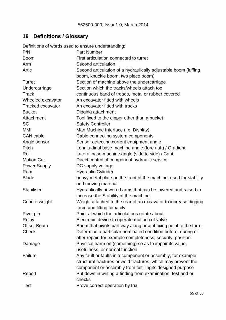
19 Definitions / Glossary
Definitions of words used to ensure understanding:
P/N Part Number
Boom First articulation connected to turret
Arm Second articulation
Artic Second articulation of a hydraulically adjustable boom (luffing
boom, knuckle boom, two piece boom)
Turret Section of machine above the undercarriage
Undercarriage Section which the tracks/wheels attach too
Track continuous band of treads, metal or rubber covered
Wheeled excavator An excavator fitted with wheels
Tracked excavator An excavator fitted with tracks
Bucket Digging attachment
Attachment Tool fixed to the dipper other than a bucket
SC Safety Controller
MMI Man Machine Interface (i.e. Display)
CAN cable Cable connecting system components
Angle sensor Sensor detecting current equipment angle
Pitch Longitudinal base machine angle (fore / aft) / Gradient
Roll Lateral base machine angle (side to side) / Cant
Motion Cut Direct control of component hydraulic service
Power Supply DC supply voltage
Ram Hydraulic Cylinder
Blade heavy metal plate on the front of the machine, used for stability
and moving material
Stabiliser Hydraulically powered arms that can be lowered and raised to
increase the Stability of the machine
Counterweight Weight attached to the rear of an excavator to increase digging
force and lifting capacity
Pivot pin Point at which the articulations rotate about
Relay Electronic device to operate motion cut valve
Offset Boom Boom that pivots part way along or at it fixing point to the turret
Check Determine a particular nominated condition before, during or
after repair, for example completeness, security, position
Damage Physical harm on (something) so as to impair its value,
usefulness, or normal function
Failure Any fault or faults in a component or assembly, for example
structural fractures or weld fractures, which may prevent the
component or assembly from fulfillingits designed purpose
Report Put down in writing a finding from examination, test and or
checks
Test Prove correct operation by trial

562600-000, Issue1.0, March 2014
56 of 58
20 Amendment / Revision Record
Issue
Number
Section / Page Amendment / Revision Description
1.0 N/A Initial Document Release
562600-000, Issue1.0, March 2014
57 of 58
+
Appendix 1 Duty Numbering
The duty number is made up of three values: Road/rail cant - active sector - Axle lock
status i.e. 2BL will be rail (0-50mm cant), sector B, Axles Locked.
Road/Rail Cant Levels 1 Road
2 Rail between 0-50mm
cant
3 Rail between 50-150mm
cant
4 Rail between150-250mm
cant (Default)
Axle status forms the last part of the duty number. Locked axle are labelled L, floating
axle U. Tracked machines have no floating / locked road duties.
Active sector
Ra
il
Ro
ad
Wheeled Tracked
Floating Locked Floating Locked
N/A
Active Sector
Axle Lock Status
+ B
The cant levels shown here are
the default values. These can
be adjusted as required during
calibration. Cant measurement
shown refers to the machine
turret.
Duty sectors originate from from 0° slew (over
floating axle) and can contain sectors from a-r.
Each duty block (i.e. Road, Rail 0-50mm cant
etc) can have different configurations of
sectors. Only the current sector is shown on
the display.
N/A

562600-000, Issue1.0, March 2014
58 of 58
Appendix 2 Interlocks
1. When the oscillating rail axle is locked the symbol shown here will appear
on the display. If the interlock was configured during installation the forward
and rear travel functions will be disabled when this symbol is visible.
2. When the oscillating rail axle is locked, PMERail will
start to monitor the equivalent UNLOCKED duty. If ei-
ther the lift capacity or the backward stability level of
the UNLOCKED duty is unsafe, the YELLOW
‘padlocks’ will be shown on the display. If the interlock
was configured during installation, the axle lock control
will be disabled preventing the axle from being
unlocked. Wheeled example shown.
The display will automatically revert back the top menu screen after ten seconds if a but-
ton has not been pressed.

562600-000, Issue1.0, March 2014
Prolec Ltd
25 Benson Road
Nuffield Industrial Estate
Poole
England
BH17 0GB
Tel: +44 (0)1202 681190
E-mail: [email protected]
Prolec Ltd® is a James Fisher Company